Pegasus Astro · PDF file8 Pegasus Astro – Copyright 2016 Rotary encoder has two...
19
Pegasus Astro Dual Motor Focus Controller v3.0 Pegasus Astro – Copyright 2016 Documentation: Dec/16 Thank you for choosing our Dual Motor Focus Controller v3.0 (DMFCv3)
Transcript of Pegasus Astro · PDF file8 Pegasus Astro – Copyright 2016 Rotary encoder has two...
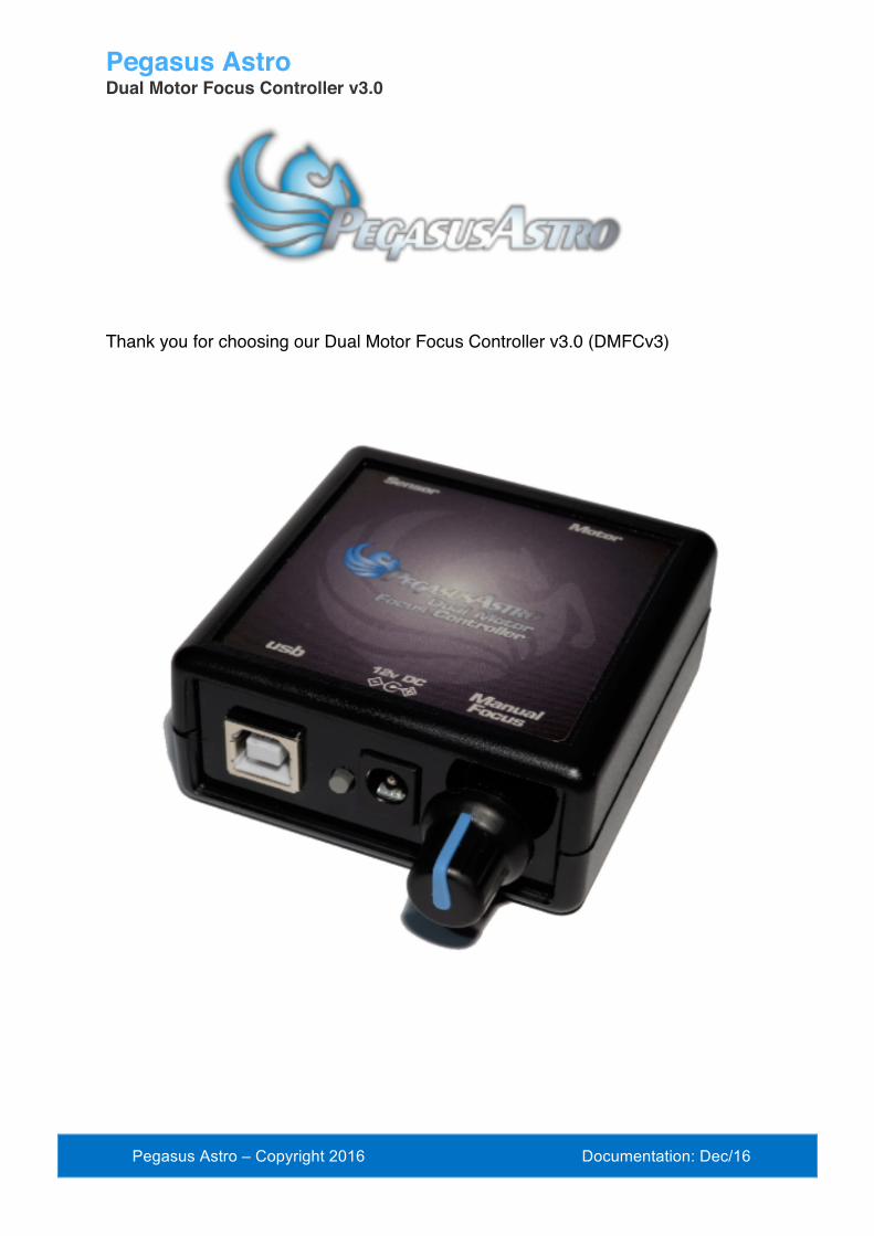
Pegasus Astro Dual Motor Focus Controller v3.0
Pegasus Astro – Copyright 2016 Documentation: Dec/16
Thank you for choosing our Dual Motor Focus Controller v3.0 (DMFCv3)

2 Pegasus Astro – Copyright 2016
Introduction The evolution of technology in astronomy requires a system which will assist the focusing of the telescope with great accuracy. Fast optics and modern camera devices require automatic focusing in every small period of time as temperature can affect focal length and modify the optimal focus position.
Pegasus Dual Motor Focus Controller (DMFC) has been developed to meet these requirements. Designed in high quality with modern electronics it can provide digital precise control of compatible motor focusers from a PC or from manual operation.
DMFC is suitable for visual astronomers and astro-photographers. Its unique design can support two modes. It can drive DC motors, by its Pulse Width Modulation duty cycle control or unipolar stepper motors for absolute position focusing. Using the click of your mouse the mode can be instantly changed from ‘stepper’ to ‘dc’ motor.
Controller can be operated by PC by its USB 2.0 connectivity. Moreover, a manual operation by utilizing the digital encoder on the side of the controller emulates the knob of your focuser. Turn the knob as it was your telescope focuser. If you press it, the steps of the motor will be reduced to 1:10.
There is a standard 2.1mm centre positive DC power connection which powers on the controller.
A dual colour light emitted diode (Green / Yellow) is fitted on the top of the unit. Each colour indicates a mode and the led can be turned on or off by its software during an observing session.
Motor output is fully compatible with “Robofocus ©” or Moonlite pin out. A cable converter (serial to mono jack) can be used for simple DC pulse motors. An external digital temperature sensor input is located near the motor connector. The digital probe of length 1.0m is supplied. The probe can be placed near the focuser so the exact temperature of the focuser / environment can be seen through the supplied software or ASCOM driver.
Controller supports absolute focusing and it stores the exact focuser position so it can be retrieved in the next observing session. Moreover, it can store max speed of the stepper motor to comply with motor specification.
The controller can be operated by the standalone DMFC software. (Available for Windows OS). It is also fully compatible with ASCOM 6.
Controller firmware supports reprogramming via the USB 2.0 connection with the help of a firmware upgrade software, for future features which may become available.
The controller has its own software drivers, applications, allowing full functionality to

3 Pegasus Astro – Copyright 2016
be quickly and effectively.
All the drivers and applications may be used together with the same, or multiple controllers.
Controller Care
• Controller is not waterproof and it should be kept clean and dry. Moisture can damage electronics and connectors.
• Do not allow solvents or chemicals to come into contact with the device • Store controller indoor in a dry room when not in use • Do not touch the internal components as they may get hot when in use
Controller Design Overview

4 Pegasus Astro – Copyright 2016
Power supply
Unit has been designed with reverse polarity protection. If you accidentally reverse the power source polarity the unit will cut the power.
The controller is fitted with a standard 2.1mm center positive DC power connection which powers on the controller. It can accept DC 9V minimum to DC 15V maximum. Please use a power supply that can provide DC 12V / 1A (at least)
Insert the 2.1mm plug on the DC power cable. Controller will initialize and the status LED will light in green color.
Motor Connector
The controller is fitted with a D Sub 9 Pin Female Connector.
• Unipolar Stepper Motors utilize first four (4) pins of D Sub 9 female connector • Simple DC Motors utilize first two (2) pins of D Sub 9 female connector. Dusty cycle
pulse width modulation (PWM) controls the motor.
Female D Sub
Stepper Motor

5 Pegasus Astro – Copyright 2016
FOCUSER CONNECTION IN STEPPER MODE PIN 1 COIL 1+ PIN 2 COIL 1- PIN 3 COIL 2+ PIN 4 COIL 2- PIN 5 - 9 NO CONNECTION
FOCUSER CONNECTION IN DC MODE PIN 1 POWER + PIN 2 POWER - PIN 3 - 9 NO CONNECTION
6 Pegasus Astro – Copyright 2016
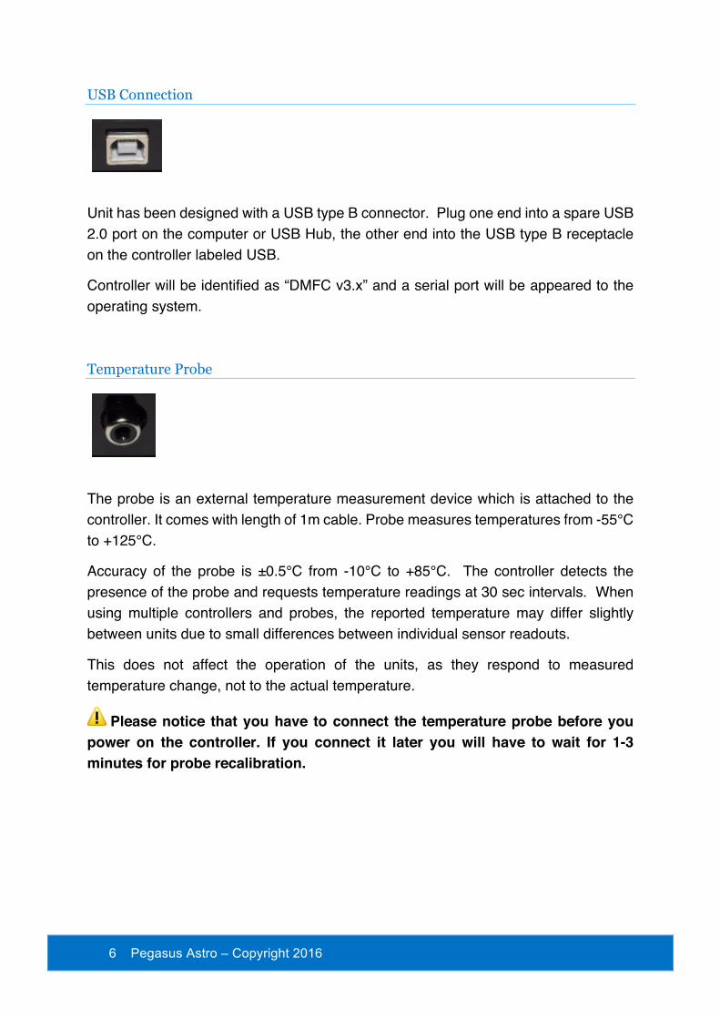
USB Connection
Unit has been designed with a USB type B connector. Plug one end into a spare USB 2.0 port on the computer or USB Hub, the other end into the USB type B receptacle on the controller labeled USB.
Controller will be identified as “DMFC v3.x” and a serial port will be appeared to the operating system.
Temperature Probe
The probe is an external temperature measurement device which is attached to the controller. It comes with length of 1m cable. Probe measures temperatures from -55°C to +125°C.
Accuracy of the probe is ±0.5°C from -10°C to +85°C. The controller detects the presence of the probe and requests temperature readings at 30 sec intervals. When using multiple controllers and probes, the reported temperature may differ slightly between units due to small differences between individual sensor readouts.
This does not affect the operation of the units, as they respond to measured temperature change, not to the actual temperature.
Please notice that you have to connect the temperature probe before you power on the controller. If you connect it later you will have to wait for 1-3 minutes for probe recalibration.

7 Pegasus Astro – Copyright 2016
Mode Selection By its unique design controller can support two motor modes. The motor selection can be achieved inside the standalone software
• Click the label of the motor mode on the taskbar. Software will ask you to switch to other motor mode (Stepper Mode or DC Mode)
•
Mode can be changed only from the software.
Status Led A dual color LED is fitted on the top of the unit. It can light in yellow or green color. The light displayed by the led indicated the status of the device.
Permanently Green Light Controller Startup Permanently Green Light Knob encoder set to normal speed Permanently Yellow Light Knob encoder set to 1/10 speed Permanently Off Controller not operational or LED
switched off from software Permanently Orange Light Digital Encoder functionality is disabled
(knob on the top)
Rotary Encoder Knob On the side of controller there is an infinite rotary knob. This digital encoder knob simulates your focuser’s knob. In every small step turn, motor will respond clockwise or anticlockwise.

8 Pegasus Astro – Copyright 2016
Rotary encoder has two presets. The fast step (50 steps in every click of your turn). and 1/10 reduction. (5 steps in every click of your turn)
Changing the presets is easy by pressing down the knob on the side of the device. You can disable the encoder functionality by keep pressing the knob for two seconds. Led will turn to orange and the encoder will not obey at your commands. Press the knob one more time and you will enable the encoder functionality again.
Emergency Stop: When you press the knob, controller will cancel every motor operation. This is useful when you need to stop the motor instantly. LED Indications Yellow Light Knob encoder set to 1/10 speed (5 steps) Green Light Knob encoder set to normal (20 steps) Orange Light Knob encoder is disabled
Please note that rotary encoder is in operation in parallel with PC commands. They both work flawlessly and update the exact position of the motor.
Technical Specifications Supply Voltage 9 - 15V DC (12V preferred) Motor Compatibility DC motor - adjustable frequency PWM
Unipolar motors Bipolar models
Motor Output DC motor, max 1 Amp Unipolar / stepper motors, max 2.0 Amps (1.0 Amps per phase) Continuous output current per channel: 1 A Peak output current per channel: 3 A Continuous paralleled output current: 2 A
USB Connectivity USB 2.0 Type B plug Thermal Sensor Resolution 9-bit Celsius temperature measurements Power Input Connector 2.1mm Centre Positive Socket Motor Connector D Sub 9 female connector Dimensions 66mm x 66mm x 28 mm

9 Pegasus Astro – Copyright 2016
Troubleshooting guide Problem Cause Cure Controller LED is off Power supply is not
connected Connect Power and wait for three green light blinks (Controller Boot)
Stepper motor does not move Check if mode is in “stepper motor” setting
Set mode to “stepper motor” setting and retry
DC motor does not move Check if mode is in “dc motor” setting
Set mode to “dc motor” setting and retry
Mode is in stepper but stepper motor does not move
Motor speed is very low or zero
Go to settings in software and set max speed of motor (try to set 400-500 steps).
Stepper motor makes strange noises
Motor has been connected with wrong cabling or a cable has been disconnected / cut (stepper motor requires 4 cables)
Check cable order is correct and retry or replace serial cable
Stepper motor makes strange noises or step gaps when accelerates
You have specified a “max speed” larger than motor can support
Go to “Settings” and limit the max speed (try between 400-600). Every stepper motor has a maximum speed or else it will jump and loose steps. Pegasus Astro Stepper Motor support max speed up to 500.
Knob on the side does not work
Check that LED is not orange colored. This means you have disabled the knob encoder functionality
Press the knob to enable the encoder. The led light will turn yellow or green
Sensor does not report temperature
Check that sensor is in place Check connectivity of the sensor. Recycle power and retry or wait for 1-3 minutes for sensor recalibration.
Controller randomly looses USB connectivity
Check that your USB cable does not exceed 5m length.
Use a shorter cable or a powered USB hub. The USB 2.0 specification limits the length of a cable between USB 2.0 devices (Full Speed or Hi-Speed) to 5 meters.
Software installation Latest software and drivers release can be found at Pegasus Support site: http://pegasusastro.com/support

10 Pegasus Astro – Copyright 2016
Please download and install the following:
• ASCOM6 Driver for DMFC • Standalone DMFC Application • USB Drivers for DMFC

11 Pegasus Astro – Copyright 2016
Standalone DMFC Application Standalone application does not require ASCOM drivers and it can configure / operate the Dual Motor Focus Controller.
In order to connect from the supplied software to the controller, you need to first configure the serial port
• Click on “Settings” icon The following window will appear

12 Pegasus Astro – Copyright 2016
• Click “Device”. A drop down list of discovered DMFC controller will appear. Choose the Dual Motor Focus Controller and click “OK”
• Press “Connect” button
• Application will connect to the controller and the “Connected” status will appear on
the bottom taskbar.
Led status You can operate the led indicator on the top of controller on demand. Click the circle “LED” icon and switch on or off the LED of the controller.
Mode status The mode selection of the controller is reported in this section of the taskbar
Mode will be reported as:
• Stepper Motor • DC Motor
Click the motor label to switch from Stepper to DC or the opposite. You will see this question box:
Motor Settings – Max Speed It’s crucial to set “Max speed” of stepper motor. All stepper motors have limits of the max speed they can achieve. If you set “max speed” faster than your motor can support, it will probably jump / loose steps and make weird noises as it cannot keep up with the controller’s steps.
• Connect to the controller • Go to settings and check “Motor Settings”

13 Pegasus Astro – Copyright 2016
• Set steppers motor “Max Speed” and click “Set”. Setting will be saved to controller’s memory (EEPROM)
• Power cycle controller to verify new setting and configure motor output.
Motor Settings - New Position If you need to change the current position of the controller, you can do it through this option.
• Type new position and press “Set” Button
• Controller will instantly set new position the value you specified. Notice that controller will not move motor. Controller will only change value of reported current position
This is very useful when you need to zero the position of the focuser or set another value. You can also zero the position of the focuser by clicking the “000” button in the top taskbar of the application.
Custom Rates You can easily set and save custom names and step / pulse values in the following section of “Setup” page.
Click “OK” and your rate settings will appear in the main window of the application.

14 Pegasus Astro – Copyright 2016
Control Motor From these buttons you will control the steps of the stepper motor or pulses from the DC motor.
• Set the “Step” to the value you want (bigger the step / pulse count, larger the movement of the motor shaft)
You can also fast select the predefined values you specified in “Custom Rates”
• Click once the “step number” button. This is how many steps the motor will move
forward (+ steps) or backwards (- steps).
Notice that “Position” indicator will change its value and will confirm your command
There are also two more buttons (<<< & >>>) that will forward / reverse accelerate the motor. Keep mouse down and the motor will start accelerating to the director you clicked.
Use these buttons only if you need to quickly move in or out your focuser
In every motor movement, final position (when motor stops) is saved after 10 secs into controller’s EEPROM memory. This will ensure that next time you power on the controller, last saved position will be retrieved from its memory.
15 Pegasus Astro – Copyright 2016
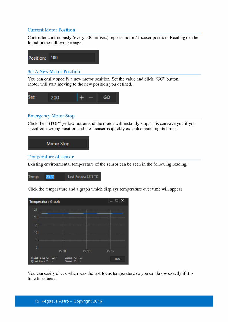
Current Motor Position Controller continuously (every 500 milisec) reports motor / focuser position. Reading can be found in the following image:
Set A New Motor Position You can easily specify a new motor position. Set the value and click “GO” button. Motor will start moving to the new position you defined.
Emergency Motor Stop Click the “STOP” yellow button and the motor will instantly stop. This can save you if you specified a wrong position and the focuser is quickly extended reaching its limits.
Temperature of sensor Existing environmental temperature of the sensor can be seen in the following reading.
Click the temperature and a graph which displays temperature over time will appear
You can easily check when was the last focus temperature so you can know exactly if it is time to refocus.

16 Pegasus Astro – Copyright 2016
Reverse Direction In case you need to invert the motor in anti-clockwise rotation you can click the “Reverse Direction” option from settings. This option can be useful if you use gears to transmit motor’s movement to your focuser.
An anti-clockwise icon will appear on the status window of the main application pointing that you have selected this option.
Maximum Position You have the option to specify the maximum steps of the motor. This will enforce the controller to disallow a motor move to the direction you are about to exceed this limit. This is a useful option to prevent the focuser to fully move in or out. Move to settings and type the numeric limit in the “Max Position” section you need to enforce. Click the “On” check button
When you try to exceed this limit the controller will deny to increase steps and it will notify you that the limit was about to exceed.

17 Pegasus Astro – Copyright 2016
Backlash Compensation Backlash, sometimes called lash or play, is clearance or lost motion in a mechanism caused by gaps between the parts. Motor’s gearbox or other components in the focuser can have an amount of backlash. Compensation will be invoked when the move in opposite of the compensation direction. Just make sure the amount specified is more than needed to remove the backlash. To enable backlash compensation, choose the extra steps you need to calculated in compensation and enable the feature by clicking ON. Setting is stored in the EEPROM and calculates the backlash steps by using PC or Manual Knob
An indication on the main status bar will notify you that the backlash compensation functionality is enabled.
Knob Encoder Disabled If you want to disable knob on the side of the controller
• Press the knob for two (2) seconds. • You can also disable it from the settings of the standalone software.
Led indicator will turn to orange and the software will report the disabled status of the knob. A red knob will appear on the status bar or the software (check following image)
Press the knob one more time to enable the encoder functionality
Firmware and Software Version
Connect to controller and click the “informational” button on the taskbar of the main application.

18 Pegasus Astro – Copyright 2016
In this window you can verify the firmware version of the controller including the version of the standalone application. Keep in mind that software supports new feature combined with the latest firmware release. Please check http://pegasusastro.com/support for latest firmware & software updates of “Dual Motor Focus Controller”.
Launch 2nd instance of the software
Click button. It will spawn a 2nd instance with different settings so you can use both of them in parallel.

19 Pegasus Astro – Copyright 2016