PEACE-TIME VALUES FROM A WAR TECHNOLOGY.
78
V ol . 29. No. 233. M ay 1943. PEACE-TIME VALUES FROM A WAR TECHNOLOGY. By Dr. Gustav Egloff.* Paper presented at the War-time Marketing Conference, American Manage- ment Association, Chicago, January 14, 1943. I ntroduction . I n a world at war one gets the impression that all forces are solely for destruction. When war ends, the new technology will more quickly, efficiently, and effectively convert the war effort into the pursuits of peace.. With the tremendous increase in research and development, the com- mercialization of processes has occurred^whicir'under normal conditions would have taken years to reach fruition. Out of.the welter of the war effort, values will flow'that will increase man’s effective span of life with greater satisfaction for living. Science has already prolonged and saved man’s life through germ- killing chemicals, new anesthetics, and synthetic vitamins. Through scientific and technical research our food supply has increased in quantity and quality. Synthetic textiles have provided us with more beautiful, durable, and sanitary clothing. Plastics will revolutionize the building arts, for the trend is to supplant many house-building and house-furnishing materials with plastics as soon as they can be released for civilian use. Plastics, together with new and more efficient fuels, will also play a dominant part in our transportation systems. Let us look at the transportation situation first. The petroleum industry will play a controlling part in this. Airplanes hurtling through the air at over 500 miles an hour, carrying 1000 or more passengers, will make all parts of the world less than twenty-four hours away from Chicago. Luxuri- ous as were the Normandie and Queen M ary for ocean travel, airships yet to come will operate with a smoothness and comfort unknown to-day. Low- cost air travel and small planes should be within the pocket-book of every American. The competitive impact of the new airplane industry on all other forms of transportation may be quite serious. Increase in air travel will be made possible primarily by the capacity of the oil industry, increased by war-time demands to produce 100 and higher octane gasoline, and by the amazing developments in airplane design, material, and construction that have been forced by the hard hand of war necessity. The same technique and the same processes that produce 100-octane gasoline in almost unlimited quantities for use in airplanes, will also mean greatly improved fuel for automobiles—in fact, at least 50 per cent, more miles per gallon. We may hazard a guess that the automobiles to come * Director of Research Universal Oil Products Company, Chicago, and President American Institute of Chemists. L
Transcript of PEACE-TIME VALUES FROM A WAR TECHNOLOGY.

V o l . 2 9 . N o . 2 3 3 . M a y 1 9 43 .
PEACE-TIME VALUES FROM A WAR TECHNOLOGY.
By D r . G u s ta v E g l o f f . *
Paper presented at the War-time Marketing Conference, American Management Association, Chicago, January 14, 1943.
I n t r o d u c t io n .
I n a world a t war one gets the impression th a t all forces are solely for destruction. When war ends, the new technology will more quickly, efficiently, and effectively convert the war effort into the pursuits of peace.. W ith the tremendous increase in research and development, the commercialization of processes has occurred^whicir'under normal conditions would have taken years to reach fruition. Out of.the welter of the war effort, values will flow 'that will increase m an’s effective span of life with greater satisfaction for living.
Science has already prolonged and saved m an’s life through germ- killing chemicals, new anesthetics, and synthetic vitamins. Through scientific and technical research our food supply has increased in quantity and quality. Synthetic textiles have provided us with more beautiful, durable, and sanitary clothing. Plastics will revolutionize the building arts, for the trend is to supplant many house-building and house-furnishing materials with plastics as soon as they can be released for civilian use. Plastics, together with new and more efficient fuels, will also play a dominant part in our transportation systems.
Let us look a t the transportation situation first. The petroleum industry will play a controlling part in this. Airplanes hurtling through the air a t over 500 miles an hour, carrying 1000 or more passengers, will make all parts of the world less than twenty-four hours away from Chicago. Luxurious as were the Normandie and Queen M ary for ocean travel, airships yet to come will operate with a smoothness and comfort unknown to-day. Low- cost air travel and small planes should be within the pocket-book of every American. The competitive impact of the new airplane industry on all other forms of transportation may be quite serious.
Increase in air travel will be made possible primarily by the capacity of the oil industry, increased by war-time demands to produce 100 and higher octane gasoline, and by the amazing developments in airplane design, material, and construction th a t have been forced by the hard hand of war necessity.
The same technique and the same processes th a t produce 100-octane gasoline in almost unlimited quantities for use in airplanes, will also mean greatly improved fuel for automobiles—in fact, a t least 50 per cent, more miles per gallon. We may hazard a guess th a t the automobiles to come
* Director of Research Universal Oil Products Company, Chicago, and President American Institute of Chemists.
L

1 36 EGLOFF : PEACE-TIME VALUES FROM A WAR TECHNOLOGY.
after the war will give new pleasure to driving, because of their improved design, speed, safety, and beauty.
In the short span of twenty-five years man has entirely revolutionized transportation through the design and construction of the automobile and airplane and petroleum products. By careful study and experiment, it is certain we can produce from petroleum better rubber than was ever obtained from trees or plants, and tyres which will give 100,000 miles or more of trouble-free service are a reasonable expectation of the future.
For years we have been led to believe th a t world leadership in research and development rested squarely on Germany, and th a t the United States was laggard. Even now statements are made from time to time to the effect th a t we are still behind Germany in research, development, and commercialization. This is not consonant with the facts. There was an element of tru th in such a statem ent during World W ar I, when the United States was short of m any necessary materials due to its reliance on Germany for pharmaceuticals, dyes, fine chemicals, potash, lenses, chemical glassware, instruments, etc. We are now completely independent of any country for these and other materials.
Prior to the previous war it was thought th a t if one wanted to study chemistry, physics, mathematics, or medicine, one had to go to Germany, but th a t day is also gone for ever. In less than twenty-five years the United States has reached world leadership in research, and has awakened to a miracle of scientific and technological development under our system of free enterprise.
Private initiative is responsible for America’s world leadership in science and industry. The tremendous effort th a t is being pu t forth in the United States, the effort th a t will -win the war, is the work of private initiative.
The impact of researches, carried on by private corporations and speeded up enormously by the war, will bring vast changes in our peace-time economy. Their research departm ents were the organizations on which many companies relied to bring them out of the depression. Their results are the backbone of the country’s mobilization for to tal war.
Obviously, in the time allotted one can but show a few highlights in the accomplishments of research.
The fact th a t many of nature’s products have been unsatisfactory has stimulated m an’s inventive faculty fortified by the vision prevailing in our industries. The tremendous co-operation of industry in the United States is responsible for the spending of millions of dollars to develop a basic idea for the welfare of mankind. No industry stands alone in achievement, as they are all interrelated through research.
The destructive nations’ efforts to rule the world must be wiped out as surely as we must defeat the insect and bacterial hordes th a t prey upon us.
H ea lt h E n g in e e r in g .
Man’s struggle to survive is ever present. He has either vanquished or domesticated large animal life. Our present battle is to overcome the ravages of rats, insect life, and bacteria; i t would seem th a t the smaller the scale of life, the more difficult is the problem of its extermination or control. Even the very nature of some of the smallest forms has presented
EGLOFF : PEACE-TIME VALUES FROM A WAR TECHNOLOGY. 1 3 7
man with some of his greatest difficulties, of discovery and eradication by chemical or physical means. Great strides in this direction have been made, bu t the ultim ate solution is still far off. Increased tempo in research and experimentation along many fronts will ultimately present the remedy, but with the vastly improved tools man is constantly providing for himself, the end is certain to be on the favourable side for mankind.
From the necessities th a t war has forced upon man have grown the scientific principles of health engineering so vitally necessary to m an’s wellbeing as a fighting force. Accurate knowledge of vast areas hitherto seldom visited by dwellers in tem perate regions has been the motive force behind a medical exploration of tropical territories th a t may well be carried over in the future development of our own hemisphere.
When it became necessary to provide troops with anaphylactic measures against tropical and sub-tropical diseases, it was the problem of the medical force to provide accurate knowledge of the type of health dangers encountered, and to provide prevention and cure of malaria, cholera, typhus, hookworm, bubonic plague, sleeping sickness, dysentery, and typhoid. Mosquitoes, rats, leeches, fleas, flukes, bats, and a host of other disease- bearing or spreading agents had to be studied and their control and extermination planned. Drugs of all types had to be ready for disease combat and the checking of infection.
In the Far Eastern and African campaigns insects and infections have beset our armies. Our men went down with malaria and other diseases. Among these are dengue fever, dysentery, tropical ulcers and sores, as well as the bites of malarial mosquitoes and tropical spiders, some as large as crabs. There is a drainage of our soldier’s vigour in this pestilential atm osphere wherein he fights, eats, and sleeps bu t a few hundred miles from the Equator. As one eye-witness expressed it about the Buna campaign :
“ . . . th a t every ounce seems to grow to 10 pounds when carried through a jungle through knee deep mud. That means giving soldiers jungle equipment, including the lightest kinds of carbines, tropical uniforms, waterproof shoes, more efficient and lighter packs, as well as smaller mosquito nets.”
W hat has research done to modify this type of torture and death to which our fighting forces are subjected? The methods of attack are chemical, physical, medical, and engineering.
An indispensable tool in the study of m an’s health has for many years been the microscope, which was discovered over 300 years ago. Slow improvements had been made in this instrum ent until a few years ago, when a revolutionary principle was discovered through the use of the electron. This made possible a magnification of over 200,000 times, compared to the 3000 from the best previous microscope.
Anti-insect sprays, delousing, swamp drainage, felling of certain trees, sanitation, oil and chemical-dust spreading, and other methods are used to keep our troops in fighting condition, and will have great value industrially and agriculturally during peace.
A number of synthetic chemicals, such as the sulpha drugs, synthetic quinine, and synthetic vitamins, are finding amazing uses on the fighting fronts. Where the World W ar I record was four deaths out of five due to

1 3 8 EGLOFF : PEACE-TIME VALUES FROM A WAR TECHNOLOGY.
germ infection of abdominal wounds, the present record is one out of five. Quoting Howard Blakeslee (New York Times, January 10, 1943) :
“ On the 2000-mile front, in all the war, only 1-5 per cent, of the Russian wounded have died. T hat is slightly higher than the remarkable recovery rate a t Pearl Harbour, 96 out of each 100. The report says the Russian recovery ra te is 98-5 per cent, of all wounded. The Russian rate is one-half of 1 per cent, worse than the Guadalcanal miracle of 1 per cent, of wounded dying.
“ The Russians claim some new medical advances of their own. When plasma is made in America, the red blood cells are thrown away. The Russians report th a t they have made a process to use these cells to manufacture blood. Nerve sections taken from the dead have been successfully grafted into the wounded. Th<j peritonea of animals, the inner linings of visceral cavities, have been used as living bandages for gaping wounds. I t is claimed th a t cure is facilitated and th a t the scars are not so heavy.
“ A compound th a t is not a vitam in' yet has the blood-clotting * effects of Vitamin K, is in use. The Russians say they have found a method to obtain thrombin in thousands of quarts volume. Thrombin is a natural clotting substance in blood.”
The latest sulpha drugs which are working wonders against infection and disease are sulphathiazole, sulphapyridine, sulphaguanidine, and succinyl sulphathiazole which have been synthesized for specific diseases. Each soldier’s k it contains first-aid doses of sulphanilimide for the purpose of checking infection a t the time a wound is received.
Pentothal, which is injected intravenously, is one of the very best of the newer anaesthetics, having no explosive hazards, as have ether and the hydrocarbon gases. In addition, the equipment necessary for its administration is simple. An injection in the arm is all th a t is required to pu t one asleep.
Bacteria, soil moulds, and moulds found in the intestines of animals or insects create chemicals th a t are highly useful in destroying infection. Penicillin, a new drug produced in soil mould, is about 100 times as effective as sulphanilimide for combating infection, and far less toxic. Gramacidin from soil bacteria, has been found to be a powerful germicide for both pneumococci and streptococci, two germs extremely dangerous to man.
One cannot pass public health without mention of the vitamins. Many diseases of a baffling nature have been due to dietary deficiencies, and have been cured on treatm ent with the proper vitamins. New methods of production, mainly chemical synthesis, have made vitamins available. Vitamin C (ascorbic acid) and Vitamin B : (thiamin chloride) are probably the most outstanding examples. In 1933 the cost of Vitamin C was §213 per ounce, and in June 1942 the price had been reduced to §1.65 per ounce. Vitamin B1 was sold for §8000 per ounce in 1935, and is now m arketed a t §15.00 per ounce. Due to the huge reductions in price, these vitamins, as well as several others, can be added to fortify various foods, giving them protective factors for health never before included in their manufacture.

EGLOFF : PEACE-TIME VALUES FROM A WAR TECHNOLOGY. 1 3 9
F o o d .
Food plays the dominating role in all nations. Rationing has h it all of us, hence our keener interest in this subject. Research has made available foods relatively new to our civilization, not alone from the standpoint of new varieties, bu t of chemicals used for treatm ent increasing their quality, size, and vitam in content.
Petroleum plays a role in the newer methods of increasing food supply. W hen oil is cracked to produce motor fuel, olefinic gases are by-products. These gases, such as ethylene, propylene, and butylenes, hasten fruit- ripening and growth. Ethylene was first used for the purpose of ripening oranges rapidly, by putting a ten t over each tree or storing the unripe fruit in a room and adding small percentages of ethylene. By using this method of ripening, the fruit could be shipped without loss due to rotting. The growth of potatoes has been stimulated by ethylene and propylene. I t has been reported th a t the speed of growth of potatoes has been increased 100 per cent, when the seedlings have been treated with ethylene. The time of growth to m aturity was shortened, while a t the same time the potatoes were more numerous and larger and contained higher percentages of vitamin C.
The Russians have studied the use of butylene gas, showing th a t it has a stimulating effect on the speed of growth of trees, such as the apple, apricot, pear, cherry, plum, peach, and walnut, bringing them to fruition much faster than without its use. Where the growth season is too short to allow the full maturing of trees, due to the inclement weather in parts of Russia, so th a t flower formation and fruit-setting are delayed, butylene has been used to hasten the growth period. The method of treating a tree is to enclose it in a ten t for two weeks before the normal or desired leafing— i.e., s tart of the growth cycle. Butylene is passed into the ten t in concentrations of one part in 100,000 parts of air a t temperatures between 69° and 100° F. for a period of 1-2 hours. Small heaters are probably used to raise and maintain the tem perature of the air around the tree, so as to obtain maximum effects of the growth inducing hydrocarbon, butylene.
Acetylene, so im portant in the production of synthetic rubber, plastics, and other materials, is being used in Australia to increase the growth of pineapple plants. Calcium carbide derived from coal and limestone is placed in the heart of the plant, and rain or dew reacts with it to produce acetylene in sufficient quantities to increase the growth of the pineapples.
In California, fruit orchards are fertilized by ammonia added to the irrigation water, which has markedly improved productivity. I t may be of interest to point out th a t this ammonia is produced from the nitrogen in the air and the hydrogen from cracking of petroleum.
The autum n crocus contains a yellow powder called colchicine, which is extracted from the plant. This powder, when applied to seeds, leaves, or buds of a plant, increases growth of fruits and vegetables to double their normal size. Colchicine also gives rise to new varieties of fruits and vegetables never known before. The colchicine acts a t a very critical point in the germination of the seeds. When cell division is ready to take place, th e cell does not divide, as is usual in nature, and the specie-bearing
1 4 0 EGLOFF : PEACE-TIME VALUES FROM A WAR TECHNOLOGY.
chromosomes remain in the seed in double the number, giving rise to new species of fruits and vegetables.
The shipping of food supplies to the United States fighting men abroad is in a critical situation due to lack of transportation. To overcome this obstacle a number of processes have been developed to dehydrate foods in order to cut down their bulk and weight.
“ Quick freezing ” of fruits, vegetables, and m eat has added materially to food supply, particularly in decentralized communities, and steel and tin in the form of cans are thus conserved. This development has great economic value for peace and war.
The impact of these researches on the food economy of the world will develop enormously, in th a t one may work out new hormones and chemical stimulators which will give rise to new plant life.
Developments already achieved present an almost incredible picture of our food supplies of the future. Obviously these developments will make i t possible to raise more food of higher nutritive quality on less acreage, with far less labour compared with present methods.
T e x t il e s a n d Cl o t h in g .
For years the silkworm was the sole producer of the raw material used in weaving fine silk fabrics symbolic of richness and luxury. Marco Polo in the fourteenth century introduced these fabrics into Europe. The products from the silkworm held leadership for centuries as a symbol of wealth. The silkworm’s job is well-nigh finished, although silk will probably find a number of special uses. The research chemists have developed synthetic silks far superior to the best th a t the silkworm can do. Rayon is one of the earliest of the silk substitutes, and was produced primarily from wood and cotton linters.
The most striking development in the textile and plastics industries in the past few years is the commercial production of Nylon. One of the main uses of Nylon was for hosiery th a t has a t least ten times the wear quality of the best silk from the worm. I t is now used largely in parachutes and for ammunition bags, in which it replaces natural silk.
S t r u c tu r a l Ma t e r ia l s .
After World W ar I a great impetus was given to the building arts. Structural steels, alloys, aluminium, concrete, synthetic stones, plywoods, insulators, plastics, and a host of other materials were made generally available. A new era in design, building, housing, and transportation, will be the afterm ath of the present war with the many new materials now produced being diverted from the war to peace. A tremendous business potential is ahead of all of us, which will strain us to the limit to fulfil the demands of building, furnishings, automobiles, and trains, etc.
Gl a s s .
For thousands of years almost no progress was made in the glass industries of the world. The only researches of moment were through the addition of minerals to give beautiful colours to the window's of the world’s cathedrals.
EGLOFF : PEACE-TIME VALUES FROM A WAR TECHNOLOGY. 1 4 1
Researches in the glass industry of the U.S.A. since World W ar I have made amazing strides in the materials th a t can be produced from sand. The U.S.A. in World W ar I was cut off from the chemical glassware and lenses of Germany, which held leadership a t th a t time. We are now entirely independent of any foreign country, for we have developed new products from sand th a t are leaving their impact on other industries in a competitive way th a t will be intensified in the peace period to come. Mass production of hard glass for laboratory use has found its way into everyday life in its use for baking and other heat-resisting utensils. In addition to this development, the present war is bringing out the utility of glass in jobs which were previously taken care of by steel, silk, and cork. Glass fibre boards for heat insulation in fighting planes have saved 5 | million pounds of aluminium and other scarce light-weight metals which can be used in building 250 Flying Fortresses. For electrical insulation, glass filaments are spun which make a flameproof wire coating for use in heavy bombers. Glass foam has found use in displacing cork in life-preservers and lifeboats. Unlike air-filled rubber floats, a puncture is not vitally destructive, since when a bullet passes through, only the cells in the immediate vicinity are destroyed. One of the outstanding uses of spun glass in the present war is as a replacement for silk and gut in surgical sutures. Spun glass is also widely used as a fireproof textile. Some of the newer optical glasses use no sand a t all, but depend on the rare-earth elements such as tantalum , tungsten, and lanthanum. The glass made from these materials is highly satisfactory for use in aerial photography lenses, since it gives more sharply defined images a t higher altitudes than was ever previously possible.
P l a st ic s .
The plastics industry was founded years ago by H yatt, an American. He was the first to work with cellulose nitrates and camphor as a plastic mass in an effort to find a substitute for the ivory in billiard balls. In general, however, the founding of the modern plastics industry occurred in 1907, when Dr. Leo H. Baekeland produced in his laboratory in Yonkers, New York, the first phenol-formaldehyde products, commercially known as Bakelite. This American research was the stimulating force th a t has brought the plastics industry to the im portant position it now holds in our war effort. World leadership in the plastics field is without question in the United States. One can be clothed from head to toe by plastics th a t are now available. One may live in a plastic house and be transported in vehicles largely made of these materials. There is no end to the variety of plastics th a t are potentially available and in the making.
These remarkable plastics have a t least 100,000 uses. Perhaps one of the most im portant a t the moment is for the production of hoods for pilots and gun-turrets on airplanes, where prolonged high visibility is so essential. One of the most im portant plastics is Plexiglass, made of methylmeth- acrylate. The flexibility of this material lends itself to forming any shape desired by moulding. In addition to clarity of vision, which these plastic windows give for a long time, they are practically shatter-proof.
I t is to be expected th a t in the automobile to come plastics will play a great part in its structure. One may expect practically 100 per cent.
142 EGLOFF : PEACE-TIME VALUES FROM A WAR TECHNOLOGY.
visibility in the new type car based on plastics. For these uses it will be highly competitive with other types of structural materials.
Much has been accomplished in the United -States in brightening life, housing, and transportation by the use of plastics of every colour. One may say th a t the period in which we are living is the renaissance of colour. This reawakening to colour values was apparent before the Global Blackout. Many plastic products form excellent media in which the commercial artist and designers have expressed their a rt in home and business interiors. Current U.S. magazines are full of beautiful illustrations of radios, electric irons, telephones, airplanes, m ilady’s boudoir, many of which are made of plastics.
The colour effect of these plastics plays a definite role in the well-being of hum anity and in our capacity for work. This industry of colour effect from glasses and plastics has not been fully exploited. However, a number of manufacturing plants have worked out colour schemes th a t raise the tempo of production and ease fatigue a t the same time. Eye-strain particularly is in general an overlooked factor in well-being and productivity. Walls of dull grey, brilliant white and black machines in many cases contribute to accidents. The fatigue factor also holds for office work, and study should be given to the relation of colour to accuracy and output of those engaged primarily in mental activity.
In general, the architect, in planning buildings, has limited himself as regards colour to a comparatively narrow range—grey portland cement, red sandstone, and grey, red, and yellow bricks, etc. Newer building plastics are available in colours as beautiful and far more practical than precious stones whose colours' they imitate. The architect could well use plastics in slabs th a t would give us colourful buildings a t low cost.
One may expect th a t the new plastics will play a competitive role with building and window-glasses. Both the plastic and glass industries will also be highly competitive with the paint and varnish industries.
S y n t h e t ic R u b b e r .
We were caught with our natural rubber supplies shut off by the devastating attacks of the Japanese, who now control over 95 per cent, of the world’s rubber supplies. In normal times the United States requires about 600,000 tons for its peace-time pursuits. Fortunately science and research in the United States were not caught napping in the knowledge and technique for the production of synthetic rubber. For a m atter of tw enty years or so, long before the fall of the F ar East, processes were available to produce synthetic rubber. The production schedule is for1,100,000 tqns of synthetic rubber for the war effort. The synthetic rubbers, Neoprene, Thiokol, and Ameripol, were in commercial production prior to the fall of the E ast Indies. The methods of producing other rubbers, such as Buna-S and the butyl-type rubbers, were also available. The U.S.A. has all the raw material necessary to produce any quantity. I t is now a question of materials and their fabrication to equipment in order to construct the plants already passed by the Government.
Neoprene rubber is based on acetylene—the same acetylene th a t induces plant growth and is the basis of a whole host of other products.

EGLOFF : PEACE-TIME VALUES FROM A WAR TECHNOLOGY. 143
Acetylene is one of the most im portant of all the hydrocarbons, and has been produced through the years almost entirely from coal and limestone in electrical furnaces. One of its primary uses for years has been in acetylene welding, and now it is used in the manufacture of synthetic rubber. Researches have been going on for years in an endeavour to use our vast natural gas and petroleum resources for the production of acetylene. There are a number of commercial units now in course of construction, one of which will produce a t the rate of 75 tons a day of acetylene, or 27,000 tons a year. I t is believed th a t acetylene will be produced a t a lower cost from processing our natural hydrocarbons than by the high-temperature electric-furnace method. The natural gas industry of the U.S.A. produced in 1942 about 3,000,000,000,000 cubic feet of gaseous hydrocarbons, part of which could supply the whole world with acetylene and its derivatives.
Thiokol is manufactured from ethylene derived from the cracking of oil, chlorine and sulphur, whereas the Buna-S rubber is produced from styrene from coal and petroleum, and butadiene derived from grain alcohol and petroleum.
Butyl rubber is based on the chemical reaction of tsobutylene, butadiene, or isoprene.
We are being geared to produce synthetic rubbers in the following tonnages:
The world’s natural rubber production for 1941 was 1,675,000 long tons, of which the United States imported 820,000 tons. W ith the tremendous number of airplanes, tanks, motor trucks, ships, trains, gun mountings, etc., the rubber demands are ever increasing, not alone for the fighting forces on the far-flung fronts, bu t for the necessary war work behind the lines. A statem ent appeared recently th a t ground tanks were obsolete due to the fact th a t the heavy guns of the U.S.A. were able to smash them. I f tliis be so, then airplane tanks, heavily armoured for low altitude flying, should be the answer, and this will call for increased quantities of rubber. Medium-size tanks require 500 lb. of rubber and pontoon bridges over 1000 lb. The gasoline tank alone of a Fying Fortress uses 500 lb. of bullet- sealing rubber, while large bombers require over 1200 lb. Gas masks use three-quarters of a pound, and battleships between 75,000 and 150,000 lb. Excavation trucks used by the Army with tyre diameters of 91 feet require about 3500 lb. There are many hundred more products requiring rubber th a t are vital in the war effort, such as blimps and barrage balloons. The latter have not been used in the United States to any extent. However, if the war reaches our shores tremendous quantities of rubber will be needed for this purpose. Rubber boats, rafts, safety vests and suits for flyers, hospital rubber requirements, etc., are also some of the products demanded from the rubber industry.
Ironically, Press dispatches from the F ar E ast indicate th a t the Japanese are cracking rubber to produce gasoline and other oils, which is an indication that they have a shortage of oil despite the fact th a t they have taken over
Tons per year.Buna-S 845.000
132.00069.00060.000
ButylNeopreneThiokol

1 4 4 EGLOFF : PEACE-TLME VALUES FROM A WAR TECHNOLOGY.
the Far Eastern oil-fields of the Netherlands and the British. As a contrast, in the United States we crack petroleum to produce synthetic rubber and gasoline.
You may well ask the question : Is synthetic rubber equal to the natural ? One may say, the synthetic product is a t least equivalent to the natural, b u t a t present it does not duplicate it. Nor is it essential to duplicate nature’s product, for the chemist’s goal is to produce rubber with far superior properties to the natural. I t has already shown far superior properties from the standpoint of gasoline, oil, and chemical resistance.' The synthetic product has greater wearing properties, and does not deteriorate readily in sunlight and air.
A number of trucks and motor-cars using synthetic rubber have gone over 35,000 miles, and one may reasonably expect a t least 100,000 miles with the amount of research going on in the laboratories of the U.S.A. The greater general strength of a synthetic tyre means less driving hazards and far better road gripping. The latter property has been thoroughly tested on wet and muddy roads. Hill tests made with a number of trucks on a muddy road showed th a t the synthetic-tyred vehicle had very little side-slipping, while the natural tyred slipped all over the road. Taxi-cab drivers advise th a t they all feel far safer in driving in mud or on wet city streets when their cabs are tyred with synthetic rubber.
The research laboratories of the United States have discovered a t least 3000 synthetic rubbers of varying properties. Some of them are exceedingly expensive to produce and others relatively low-priced. One may state th a t synthetic rubber for tyres will be highly competitive with the natural rubber and in mass production synthetic should be less than 15 cents a pound. Natural rubber has sold through the years a t prices varying from 3 cents to §3.00 per pound.
We are in a rubber crisis which may mean th a t all motor vehicles not used in the war effort will cease operating in order to be sure th a t all our fighting fronts will have sufficient rubber for ultim ate victory.
Synthetic rubber m ust be provided a t the rate of a t least 1,100,000 tons a year called for by the Baruch Committee. Never again should the U.S.A. be caught short of rubber whether in war- or peace-time.
A v ia t io n D e v e l o p m e n t s .
Scientific, technical, and industrial miracles are faking place throughout the U.S.A., not the least of which is in the airplane industry. In a few years production of airplanes has stepped up from less than 1000 per year to over 48,000 in 1942, -with 100,000 projected for 1943. I t is not solely a question of the number of planes, bu t'their design, quality, and size based on incorporating the knowledge gained on the fighting and research fronts.
Extraordinary strides have been made in the fabrication of airplane engines, propellers, and bodies. The materials of construction are now of aluminium, magnesium and their alloys, stainless steel, plywood, and plastics. These will be highly competitive after the war. Aluminium alloy forgings for cylinder heads stepped up the horse-power of the engines 15 per cent, as well as decreasing its weight. Seversky reported th a t a32,000 horse-powered airplane was in the making, using four 8000 horse-
F.GLOFF : PEACE-TIME VALUES FROM A WAR TECHNOLOGY. 1 4 5
power engines. A Flying Fortress, the U.S. Army B-19, is an 8800-horsepower airplane, with a 36,000-lb. high explosive carrying capacity. In contrast, “ Air Jee p s” of 65-100 horse-power are in our fighting forces on the Pacific and African fronts. They are used for fighting, since they carry Stokes mortars and heavy machine guns, as well as 100-lb. bombs, and have a range up to 500 miles with an altitude averaging about 1000 feet. They are also used for observation in place of the old-type balloons, for courier duty, auxiliary scouts, and as advanced guards by the striking forces. In peace-time these planes were the well-known Piper Cubs, Aeroncas, Taylor Crafts, Fairchilds, and Stinsons.
The giant strides made by the airplane industry are a t least matched by the oil industry in producing the 100 and higher octane gasoline and the necessary lubricants to operate the hundreds of thousands of aviation engines.
There are many chemical processes involved in the production of our aviation gasoline. The 100-octane gasoline is a 100 per cent, development of the oil industry of the U.S.A. We have far superior aviation gasoline and lubricating oils than the Axis Powers have available. The octane ratings of aviation gasoline which were collected from shot-down German planes averaged about 87. I t has been reported th a t the German invasion of England in September 1940 was stopped by the R.A.F. because their fighting planes were powered with 100-octane fuel, while the German planes were fueled with 87-octane.
The importance of high octane ratings in gasoline for airplanes is strikingly shown in the performance of 87-octane compared to 100 in a bombing plane, particularly as to speed, rate, and time of climbing to maximum ceilings and manoeuvrability of the plane. Comparative tests of 87 versus 100-octane gasoline in a bombing plane showed th a t it took nineteen minutes to reach an altitude of 26,000 feet for 87-octane, whereas the 100 required only twelve minutes. The absolute ceiling of the plane in round numbers was 37,000 versus 33,000 feet for the lower octane-fueled plane.
The newest transport plane, called “ The Constellation,” just tested, will carry fifty-two passengers with a speed greater than the Japanese Zeros. The plane can fly a t about a seven-mile ceiling far above storm conditions, while ordinary cruising altitudes are about four miles. The Constellation can cross our continent in one eight-hour hop using more than 8000 horsepower with the remarkably low fuel consumption of one gallon of gasoline per mile.
Co n c l u sio n .
World W ar I I may not be a to tal loss for humanity. A tempo never before attained in the U.S.A. has been reached with a collaboration and exchange of knowledge between heretofore highly competitive groups. New materials now in war production will have great peace-time values. We will also have access to a vast amount of knowledge and experience which has been accumulated as the result of hectic years of war. Man’s life vull be prolonged, his health, mentality, imagination, and productivity increased, and the pain and irritations of life will be reduced to a minimum.


M a y 1943. 149 a
ABSTRACTS.P A G E
Geology and Developm ent . . . 1 5 0 a
Geophysics ................. . . . 1 6 2 aDrilling . . . 1 6 4 a
Production. . . . 1 6 9 a
Transport and Storage ... . . . 1 8 5 aG as... . . . 1 8 6 a
PA G ER efining and Refinery Plant ... 186 aChemistry and Physics o f Petroleum 188 a A nalysis and Testing ... ... 191 aSpecial Products ... ... ... 191 aPublications R eceived ... ... 197 a
A UTH O R IN D E X .
The numbers refer to the Abstract Number.
The original papers referred to in the abstracts marked with an asterisk may be borrowed by Members from the Institute Library.
A lbright, J . C., 464 A lexander, R . D., 473 Anderson, D. D., 445 A ppleby, P . W ., 445 A pplegate, F . B., 446,449 Arsdell, P . M., 484
Baker, W. L ., 440 Ballagh, J . C., 445 Bam es, C. H ., 473 Barstow , 0 . E ., 473 Baylor, A. S., 473 Blair, C. M., J r . , 473 Block, R . B ., 488 Blondeau, E . E ., 445 Bodey, C. E ., J r . , 473 Bodine, A. G., 445 B oynton, A., 473 Briggs, F ., 465 Brooks, L . T ., 401 Brown, L . R ., 445 Brown, S. A ., 473 Bruce, W . A ., 463 Bulkley, W . P ., 445 B urke, M. P ., 473 Burns, E ., 473
Cabeen, W . R ., 431 Cam pbell, J . , 492 Campbell, W . B ., 473 Cantor, J . , 489 Carson, L ., 486 Church, W . L ., 445 Cobb, A. W ., 486 Coberly, C. J . , 473 Collins, A. J . , 473 Collins, J . H ., 447 Craft, B. C., 444 Crites, W . J . , 473 Crone, R . R ., 445 Crump, J . S., 473 C uthrell, A . E .," tib
D avenport, L . G ., 473 D avid, H ., 412 D avid, W . A. L ., 500, 501 Doll, H . G., 437 Driscoll, E . P ., 489
E ckel, J . E ., 473 EglofE, G ., 484, 499, 503
F earon , E ., 445 F innegan , J . K ., 491 F ischer, K ., 473 F o ste r, J . L ., 473 F o x , C. L ., 445
G a rre tt , H . U ., 473 G em an t, A ., 487 G ough, J . E ., 445 G raham , A. H ., 445 G raham , A . M ., 445 G ranger, P . H ., 445 G ratehouse, J . G ., 445 de G roote, M ., 473
H alp en n y , L . C ., 461 H am o n , W . M ., 445 H a re , D . G . C., 445 H a r t , M. L ., 473 H aynes, C. J . , 445 H e ld e n b ra n d , A . P ., 445 H end rickson , R . E ., 473 H obbs, O. K ., 473 H obson , G . D ., 435 H okauson , M ., 445 H ooser, D . B ., 473 H o o t, C ., 411, 416 v a n H o rn , J . B ., 473 H ow ard , W . V ., 403, 405,
406, 427, 433 H ow ell, L . G ., 445 H u n te r , A . L ., 431 H u n tin g d o n , R . L ., 472
In g ra m , T . R ., 423
Jack so n , "W. H ., 452 Jo h n so n , G. D ., 445
K eiser, B ., 473 K em ler, E . N ., 457, 466 K ing , S. P ., 460 K in ley , M. M ., 445 K irk p a tr ick , R . L ., 473 K now lton , D. R ., 399
L ange, P . W ., 445 L a rso n , A. D ., 473 L au ris to n , V ., 424 L in fo rd , H ., 485 L ohm ann , M. R ., 468, 470 L ong , S. W ., 445 L undeen , C. A ., 445
M achen, R . W ., 480 M aier, A. R ., 445 M artin , W . A ., 472 M iles, J . N ., 459 M üler, H . C., 456 M oeller, A ., 473 M ontgom ery , J . S., 439 M orton , F ., 490 M owrey, L . D ., 473 M cC arty , G. M., 473 M cCaw ley, E . L ., 491, 495 M cF arlan d , H . A ., 445
N elson, W . L ., 493, 498 N oble, W . B ., 445 N o rd m an , D . V ., 484
O’D onnell, J . P ., 407 O lm stead , E . H ., 445 O sborn , A ., 489
P a n k ra tz , H . J . , 473 P en d le to n , H . R ., 473 P en ick , A . J . , 445 P en ick , K . T ., 445 P erk in s , F ., 444 P h ü lip s , P . L ., 445 P ic a rd , J . B ., 473 P o tts , E . L ., 473 P rice , R . B ., 473 P rin ce , C. A ., 473
R ap h a e l, H . A ., 445 R eaves, R ., 467 R ic h ard s , A. R ., 490 R itzm a n n , O. F ., 473 R ollins, J . F ., 481 R u th , A. P ., 473
Saw don, W . A ., 430, 462
S co tt , A. B., 473 Shaw , J . F ., 445 Shaw , S. F ., 451, 453 S hu te , P . G., 502 Sim ons, H . F ., 408, 413,
420S in ton , J . A., 502 S itto n , H . W ., 445 S itto n , T . H ., 445 Sm iley, T . F ., 415, 417,
421S m ith , D . M ., 445 S m ith , W . G. L ., 445 Snider, L . C., 401 S tah l, F . R ., 472 S tepanoff, A. J . , 483 S te r re tt, E ., 450, 455 S tew art, J . P ., 474 S tockm an , L . P ., 410 S tra it, O. L . A., 491 S tru th , H . J . , 429 S u llivan , A. P ., 445 Sutliff, W . N ., 473
T aliney , P ., 445 T ay lo r, R . G., J r . , 473 Tem ple, C. V ., 473 T huesen , H . G ., 468, 470 T higpen, C. H ., 432, 434 T u tto n , F . S ., 473
U ren , L . 0 ., 436, 442
V en tresca , A., 445 V en tresca , E ., 445 V olpin, A . S ., 445
W agner, E . M., 473 W ickersham , N . W ., 445 van W ingen, N ., 448 W in te r, A. B., 438 W iley, R . E ., 445 W illiam s, N ., 454, 469,
471W olfe, H . J . , 504 W oodm ansee, H . D ., 473
Z aba, J . , 443 Z iegen-H ain , W . T ., 49
N

1 5 0 a ABSTRACTS.
Geology and Development.399.* Production Outlook for 1943. D. R . K nowlton. World Petrol., January 1943, 14 (1), 34.— The proved oil reserves of U .S.A . are about 20,000,000,000 brl., which would take 30-50 years to produce, and the present, or an increased, rate of production cannot be m aintained for long unless additional reserves are discovered at a rate at least equal to the rate of production. I t seems likely th at U.S.A. will have to supply more than its proportionate share of oil production during the war, and it is agreed th a t the demand for all typ es of products in 1943 w ill exceed the demand of 1942.
A general and substantial increase in the rate of production from most of the present fields m ust be considered as an emergency measure which should be adopted only as a last resort. A lim ited number of fields in the south-w est have an important excess of unused efficient producing capacity, but th is is not readily accessible because of transport difficulties arising from the war. Production in excess of the maximum efficient rate accelerates the decline in productive capacity, and reduces the recoverable reserves in m any cases. H ence the m aintenance of reserves at a level sufficient to m eet demands is encouraged.
In the last four years w ildcatting results have been disappointing, w ith a diminishing discovery of reserves per w ildcat. In the three-year period, 1936-1938 inclusive, an average of 2263 w ildcats were drilled each year, and an average of 806,000 brl. of new reserves were discovered per wildcat. The corresponding figures for the three- year period 1939-1941, inclusive, were 2963 w ildcats per year, and only 216,000 brl. of new reserves per w ildcat. Since 1934 th e number of fields discovered per year has increased, but the average size of the new fields has fallen from nearly 20,000,000 brl. per field in 1934 to 1,200,000 brl. per field in 1941.
A bout 3100 w ildcats were drilled in 1942, and based on the poor results of previous years 50% more w ill be required in 1943. 11,500 developm ent w ells are plannedfor 1943. The order of priority in the allotm ent of materials w ill be first wildcatting and related exploratory wells, repair and maintenance of producing wells, and lastly developm ent wells.
In order th at the smaller number of developm ent wells in 1943 will give adequate production, locations m ust be carefully selected, and th e m ost efficient production technique applied. Old wells m ust be reworked, and repressuring, pressure m aintenance, and water-flushing applied. G. D . H .
400.* Well Completions of 1942 34% under 1941. Anon. Oil W kly, 11.1.43, 108 (6), 33.— 21,217 w ells were com pleted in U .S.A . in 1942, 34% fewer than in 1941. In th e Middle W est and Upper Mid-Continent, drilling in 1942 was curtailed by 25- 50% , in K ansas 28%, in Oklahoma 34%, in Indiana 32%, in Illinois 46%, in Ohio 36% , in K entucky 50%, in Michigan 25%, in New Mexico 3-5%, in Arkansas 32%, in N orth Louisiana 40%, in South Louisiana 44%, in Mississippi 50%, in Texas 50%, in California 27%, in Colorado 28%, in Montana 23%, and in W yoming 29%.
Tables give, by States and districts, details of drilling activ ity on 1st January, 1943, and th e numbers of rigs operating on 1st January and 1st December, 1942; also th e typ es of com pletions in December 1942, cum ulative data for 1942, and the changes w hich have taken place as compared w ith 1941. G. D . H.
401. The Petroleum Shortage in the United States. B. T. Brooks and L. C. Snider. Oil Gaa J ., 21.1.43, 41 (37), 26.— If the rate of finding new oil shown in the U.S.A. in the last three years continues during th e n ext three years, and production is forced to m eet current needs, th e damage to m any fields w ill rapidly accentuate the oil shortage, w hile estim ates of net ultim ate producible oil from known reserves will have to be revised sharply downwards. R . K . D avies, W. V. Howard, W . P. Cole, E . L. DeGolyer, and H . B . Soyster have all pointed to declining discovery rates and other signs of a possible shortage. However, it is alm ost certain th at sufficient oil can be produced to m eet requirements in the next tw o years, but w ith the declining discovery rate and decline in production from existing fields it is equally certain that th e critical rate of production of m any fields w ill be exceeded, w ith consequent damage and reduction of u ltim ate recovery. In this sense a shortage has already developed.
Proven reserves are generally agreed to be 19,000,000,000 to 20,000,000,000 brh, or 5,000,000,000 brl. more than in 1936. The existence of a critical rate of production

ABSTRACTS. 151 A
has been recognized, and to obtain a high recovery by m eans of the optim um rate of production calls for a much larger reserve than when the old flush m ethods of production were practised.
For m any years about 50% of the U .S. production has been from new flush wells constituting about 2% of the to ta l producing wells. Since the greater efficiency of restricted production has been dem onstrated th e estim ates of recoverable oil have been revised upwards, both for old and for new fields. B u t this revision would be nullified if efficient rates of production are exceeded.
After allowing for shrinkage and connate water, it is now estim ated that the ultim ate recovery of oil in some fields has been as high as 80% or even 90%.
I t is not certain th at substantially increased production would be obtained by raising the price of oil to induce greater discovery effort.
Venezuela’s oil output m ight be restored to its former level if adequate transport with naval protection were available. There is little likelihood of a substantial rise in Mexico’s oil production in the im m ediate future.
I t does not y e t seem necessary to turn to oil from coal and shale to avert a shortage, and such a step would not be profitable w hile oil prices are at anything like their present levels.
The question of an adequate supply of crude oil during th e w ar is further com plicated by the need to m anufacture enormous quantities of high-octane aviation fuel, to m eet an increased demand for fuel oils, and to provide raw materials for the manufacture of synthetic rubber, toluene, and other special products. Q. D . H .
402.* Alberta Reached Top Production in 1942. Anon. Oil W kly, 25.1.43, 108 (8), 42.—The Alberta oil production is estim ated to have been 10,150,000 brl. in 1942, compared w ith 9,908,000 brl. in 1941. T he 1942 peak rate of^production was in February and March w ith 30,000-31,000 brl./day. A t the end of the year the production was at the rate of 27,600 brl./day, due to a slump in drilling in proven and prospective oil areas.
Much of the Alberta production has gone to aid the construction of th e Alaskan highway, while 87-octane fuel has been provided for the Commonwealth Air Training plan. Preparations have been m ade for th e production of 100-octane fuel.
U. D. H.403. Proven Reserves. W . V. Howard. Oil Qas J ., 28.1.43, 41 (38), 64-66.— On 1st January, 1943, the U .S. proven oil reserves were estim ated to be 20,675,899,000 brl., 543,140,000 brl. less than th e revised estim ates for 1st January, 1942. New fields added 322,808,000 brl. to the reserves in 1942, and extensions added 518,580,000 brl. The corresponding figures for 1941 were 486,935,000 brl. from new fields and1,009,175,000 brl. from extensions. During 1942 the reserves of Colorado, New Mexico and North Louisiana increased. In California the reserve figure fell during 1942 from 14-5 to 12-8 years’ supply, due to lack of discoveries and to increased rate of production. Transport difficulties caused production to be reduced in parts of Texas, and therefore in m ost of Texas the reserves rose in term s o f years’ supply. The new additions to reserves in Oklahoma were 60% below the output, and in Kansas the discoveries were 50% of th e output. There w as decided over-production in Illinois, Indiana, Michigan, Mississippi, and Nebraska.
The revision of the reserve estim ates of 1st January, 1942, have been upward throughout the U .S .A ., bu t th is revision does not increase the estim ates of immediately recoverable oil, since m ost of the fields involved are either producing to capacity or producing at a rate consistent w ith good engineering practice.
While the discoveries in 1942 were as numerous as in 1941, the average reserve of each was only two-thirds of th e 1941 figure. N o major fields were found in the northern extension of th e production in th e San Joaquin Valley. California's ability to produce has been increased by re-drilling several old heavy-oil fields. In W yoming deep pays discovered,in old fields were th e greatest in interest, except for an oil find on the northern side of the D enver basin. N ew trends parallel to the main Artesia— Vacuum fields have been found in N ew Mexico, Square Lake being the m ost im portant discovery. The Ellenburger is proving of increasing importance, and production is extending to the north-w est in th e Permian pays. Many sm all fields have been found in North Central Texas.
Many areas have been tested to th e low est possible producing horizon. In the
1 5 2 a ABSTRACTS.
E astern States no im portant production has been found below the top of the Trenton, and th is form ation has given little oil east of the Cincinnati Arch. Illinois and Michigan have production possibilities w ithin a few thousand feet of present levels. N o Cambrian production has y e t been found in Oklahoma, but Kansas has some Cambrian production. The Ellenburger possibilities are of prime importance in N orth T exas and in W est Texas. Lower Cretaceous and Jurassic horizons have not been tested in E ast T exas and in the adjacent parts of Arkansas and Louisiana. Much Tensleep and Embar production has been found in the R ocky Mountain area, where th e Palaeozoic offers lower possibilities.
A table gives by -States and districts the estim ated reserves as of 1st January, 1942, and 1st January, 1943 ; th e reserves due to 1942 discoveries and extensions, and th e to ta l years’ supply as of 1st January 1942, and 1st January, 1943. G. D. H.
404. Discoveries and Extensions by Districts. Anon. Oil Gas J ., 28.1.43, 41 (38), 66-71.— The discoveries and extensions are listed by States and districts, w ith their nam es and locations, producing horizon, proven acreage, formation thickness, and estim ated reserves. Maps show the positions of the new discoveries and extensions.
G. D. H.405. Wartime Regulations Sharply Reduce Drilling Operations During 1942. W. V.H oward. Oil Gas J ., 28.1.43, 41 (38), 72.— In 1942 18,150 wells were completed, 40% fewer than in 1941. The fall w as due to unsatisfactory prices, M-68, and a lack of locations.
E xcept for the new Burbank field in K entucky, w ells in that State, and in most of Ohio, W est Virginia, and in all of N ew York and Pennsylvania, are sm all producers, so th a t w ells drilled under present price conditions are generally unprofitable. The in itial outputs in Illinois, Michigan, and Indiana are generally higher, but the lack of locations affects th e position. Multiple completions in these three States make profitable w ells w hen all the producing horizons are within depths wherein the 10- 20-acre spacing ruling operates.
In Kansas, Peace Creek and Lindsborg were active throughout 1942, and many extensions are reported from the older fields, chief among which was the merging of several smaller pools into th e Kraft-Prusa field. I t is possible th at Hall-Gurney, Gorham, and Big Creek m ay eventually merge. Drilling dropped by nearly 50% in Oklahoma in 1942, and it also fell sharply in the Gulf Coastal district. The decline in drilling was less in the R ocky Mountain States and in California than elsewhere. The average footage of the w ells drilled in California last year w as 1704 ft. less than in1941.
There seem to be few areas in U .S.A . where there is m uch possibility of increased drilling in 1943, and unless there is price relief, increased transport, and some relaxation of drilling restrictions, it is unlikely th a t m any more than 16,000 wells w ill be drilled in 1943.
A table gives b y States and districts the total completions in 1942 ; the numbers of oil, gas and dry wells, and the footage ; the to ta l number of wells in 1941. Curves show th e total com pletions, numbers of dry holes, and the average prices year by year since 1910.
406. Production Stays at Peak Level. W . V. Howard. Oil Gas J ., 28.1.43, 41 (38), 78.— During 1942 U .S .A . produced 1,384,542,000 brl. of oil, 7,378,000 brl. less than in1941. 85-8% of the 1942 to ta l came from Texas, California, Oklahoma, Louisiana, Illinois, and Kansas. Louisiana and K ansas had their peak outputs in 1942, and California approached its 1938 peak. During 1942 the Illinois and Oklahoma outputs declined by 22,268,000 brl. and 16,406,000 brl. respectively, in spite of heavy demands. The K ansas output rose by 14,980,000 brl. in 1942, w hile the N ew Mexico production fell by 6,567,000 brl., a fail which can easily be removed w hen transport is available. Indiana gave more oil in 1942 than in any year since 1905. The developm ent of several good fields caused a substantial rise in production in Michigan in 1942. The M ontana output was a t a peak, and W yom ing’s production at its highest level since 1924, while Colorado gave more oil than in any year since the late tw enties.
The production is tabulated by States yearly since 1935, and curves show the annual production of the leading States since 1930. G. D. H.
ABSTRACTS. 1 5 3 A
407. World Production Slumps but Revival this Year is Indicated. J. P. O’Donnell. Oil Oas J., 28.1.43, 41 (38), 94.— I t is estim ated that in 1942 the world oil production totalled 2,062,500,000 brl., compared w ith 2,227,125,000 brl. in 1941. The effect of lack of transport was 75% greater than th at of destruction of fields in reducing the total output. Thus lack of transport reduced the production of Venezuela and Colombia by 86,500,000 brl. in 1942. The North American production fell by24,360,000 brl., the bulk of the decline being in U .S.A ., although Mexico experienced a further decline, largely due to transport difficulties. The Canadian output rose by 3%.
Venezuela’s production fell 32% (72,350,000 brl.) and Colombia’s production fell 57% (14,050,000 brl.) in 1942. U ntil tanker m ovem ents are easier neither country is likely to return to a state-of higher production. Both countries had new discoveries in 1942. Trinidad’s output of oil rose in 1942, and Argentina had a 7% rise.
During 1942 the Maikop fields were captured by Germany and the pipe-line outlet from Grozny was interrupted. The Germans also gained partial control of the Volga. A doubling of the U ral-V olga production to 100,000 brl./day offset these Russian losses to some extent. The Hungarian oil output is said to be 12,000 brl./day, and possibly 15,000-17,000 brl./day.
The Netherlands and British E ast Indian and Burmah fields were captured by Japan in 1942, and th is increased Near E ast developm ent. Japan has probably derived little oil so far from her conquests.
The 1943 world oil production is unlikely to reach the 1941 level. G. D. H.
408. Permian Basin, Panhandle : Ellenburger and Clear Fork Provide Important Discoveries in Basin. H . F . Simons. Oil Oas J ., 28.1.43, 41 (38), 113.— During 1942 two new Ellenburger pools, Monahans in Ward County and Embar-Ellenburger in Andrews County, gave som e indication of the deeper possibilities in the Permian Basin. Fullerton in Andrews County was the major Clear Fork discovery, the discovery well being com pleted a t a depth of 7280 ft. for 707 brl./day of 44-gravity oil. This pool now has ten w ells averaging 600 brl./day initially, w ith a pay-zone 150- 500 ft. th ick ; it m ay becom e a major pool and establish a new trend between two lines of major developm ent. The E m bar-Perm ian pool, another Clear Fork find, came in at 6210 ft. for 264 brl./day. Ellenburger production has been developed in the same pool. The Clear Fork Monahans discovery w as made in a w ell which was intended to test the Ellenburger. The Monahans (Ellenburger) pool has 280 ft. of pay, topped at 10,082 ft. in the discovery w ell which came in a t 2852 brl./day. Geophysical work has shown the Monahans structure to be large.
Nine more Ellenburger producers have been com pleted at Barnhart. A t the end of 1942 the Slaughter pool covered 72,000 acres, and it has not y e t been defined on the north side. The San Andres lime pay averages 100 ft. in thickness.
Fifty-nine exploratory w ells were drilled in the Permian Basin in 1942 to an average depth of 3500 ft. Lack of outlets curtailed production in this area.
Tables give the cum ulative production and estim ated reserves on 1st January, 1943, and the number of wells in each field of W est Texas and the Panhandle, together with the completions in 1942, and the number of com pletions and footage each month.
G. D. H .
409. Square Lake Develops into Major Pool. Anon. Oil Oas J ., 28.1.43, 41 (38), 117.—Ninety-nine oil wells and a sm all gasser have been completed at Square Lake in South-east New Mexico. The discovery w ell was completed at 2903-2978 ft. for 200 brl./day. Maljamar has thirty-five new producing wells in the Whitehorse and the Queen lime. During 1942 interest w as revived in the Jackson-Gray burg area, which has a pay zone in the W hitehorse lime at about 3300 ft.
Oil is found at about 500 ft. in the Shallow R ed Lake district, where tw elve wells were completed w ith average initial outputs of 50 brl./day. A t E ast Lusk seven oil wells have been completed at a depth of 2700 ft. w ith an average potential of 200 brl./day from the W hitehorse lime. The Arrowhead pool has been extended to the north.
Shows have been found at about 5000 ft. in the Permian a t Langlie in Lea County, and another Lea County w ell has swabbed a little oil.
The 1942 well completions in South-east N ew Mexico are tabulated, along w ith the cumulative production and estim ated reserves on 1st January, 1943. G. D . H.
410. Four Small Fields Found in Caliiornia in 1942. L. P. Stockman. Oil Gas J .,28.1.43, 41 (38), 118.— California’s crude oil reserves were substantially reduced in 1942, in which year tw o gas-fields and the Antelope Plains, E ast Strand, Buena Park and H olser oil-fields were discovered. These fields are not of major importance. The reduction in reserves was aggravated by the lack of permission to drill to the Tar zone a t W ilm ington. A similar situation obtains a t Inglewood, where drilling in the Sentous (Miocene) zone has been suspended. The W ilmington Tar zone may have a reserve of 50,000,000 brl., but th is is not y e t proved.
Production in 1942 in California was at the highest rate for a number of years, and it m ay be at a still higher rate in 1943. 556 oil w ells and 25 gas wells were completed in 1942 out of a to ta l of 828 wells. I f the percentage of failures in 1943 is as high, 1000 w ells w ill have to be drilled. None of the w ildcats shows great promise, and interest in the Cretaceous has declined since gas only has so far been found. Several fields have proved deep zones w hich w ill have to be produced if new prolific fields are not discovered in 1943.
California is not producing to capacity, because of bottlenecks.I t is intended to use the P laya D el R ey field for storage of the surplus gas produced
in the summer.The cum ulative production and the estim ated reserves on 1st January, 1943, are
tabulated by fields, and there is a summary of the types of completions in the various fields, and the numbers of com pletions and the footage drilled each month.
G. D. H.411. Oklahoma : Pauls Valley and East Watchorn Pools are Leading Discoveries in1942. C. H oot. Oil Gas J ., 28.1.43, 41 (38), 125.— The 1942 oil production in Oklahoma w as bolstered to some exten t by edge w ells and reworking programmes. Oil w ells constituted only 46% of th e completions. F ifty new oil- and gas-fields, extensions, and new zones were opened in 1942, w ith Pauls Valley probably the best find. Pauls V alley produces from the W ilcox and Pennsylvanian, and the field has been defined a t its northern and southern ends.
The Apache pool has been extended to the north-west. Late in 1942 the Ardmore Springer sand pool was opened at a depth of 3079-3302 ft. Further wells have been com pleted in th is pool. The Cumberland pool has been extended to the w est, and a new pay was discovered at a depth of 5472 ft.
Tables give the cum ulative production and th e estim ated reserves by fields on 1st January, 1943, together w ith the total w ell completions and types. G. D. H.
412. Western Side of Illinois Basin Produces Outstanding Fields of Year. H . David. Oil Gas J ., 28.1.43,41 (38), 131.— The high discovery rate was m aintained in the southern half of Illinois in 1942, but no large flush pools were found. H ence the oil reserves declined for th e first tim e since 1937. 106,282,000 brl. of oil were produced in 1942, and 1809 w ells were com pleted, compared w ith 3838 w ells in 1941. During 1942 there w as an increase in activ ity in the Louden and Centralia-Salem areas and on the w estern rim of the basin, where the D evonian and Trenton limes were the main objectives. D evonian production w as found a t Boulder and Bartelso South, and Trenton production at St. Jacob. Late in December 1942 a 700-brl. w ell was completed in the D evonian 50 ml. north-west of the nearest Devonian production at Louden.
The Boulder field has been producing from the Benoist, but late in 1942 a second D evonian w ell was com pleted. St. Jacob is the m ost prolific Trenton field in Illinois, and has encouraged the drilling of further Trenton tests on the w estern rim of thebasin. .
The Covington pool covers 1200 acres, and produces from the Aux Vases, Levias, and McClosky. I t has already given 1,159,000 brl. of oil. The Blairsville and Markham City pool w ells have high initial outputs from the A ux Vases and McClosky. Oil is obtained from the Cypress, A ux Vases, and McClosky in th e Iola field.
A new pay, th e Glen D ean lim estone, has been found in the middle of the Chester series, and is giving oil a t South Sailor Springs. E arly in 1943 D evonian production was discovered in the Patoka field.
The cum ulative production and estim ated reserves on 1st January, 1943, are tabulated by fields, and there is a sum mary of the types of com pletions and the number of com pletions each m onth in 1942. H. H.
1 0 4 A A B g ^ A O I S .
ABSTRACTS. 1 5 5 a
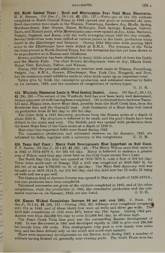
413. North Central Texas : Bend and Mississippian Pays Yield Many Discoveries.H. F. Simons. Oil Oas J ., 28.1.43, 41 (38), 137.— Forty-one of the 105 wildcats completed in North Central T exas in 1942 opened new pools or extended old ones. Bend discoveries were made in the W asson, Forestburg, Sanders, Joy, Hoefle, Spring, Worsham-Steed, E ast Bryson, Eanes, M cKnight, Park Springs, Kisinger, Garvey, Daws, and Hobart pools, while Mississippian pays were opened at Joy, Alma, Mathews, Padgitt, Ragland, and K nox, w ith the w ells averaging about 1000 brl./day initially. Several Ordovician tests were drilled at various points in the basin, production being found in the Ellenburger and Simpson. During 1942 fifty-nine w ells proving 2400 acres in the Ellenburger have been drilled at K.M .A. The presence of the Viola has been proved in N orth Central Texas, but the formation has not yet been shown to be as productive as in K ansas and Oklahoma.
Strawn production has been obtained in m any fields which yield oil from the Caddo and the Marble Falls. The chief Strawn developm ents were at Joy, Illinois Bend, Mount View, K etchum , Talbot, and W atson.
During 1942 the principal additions to reserves were made at W atson, Forestburg, Padgitt, Joy, K.M .A., Strawn, Ellenburger, N ew York City, Ringgold, and Ross, but the numerous sm all additions m ade in other fields make up an im portant total.
Tables give by fields th e cum ulative production and estim ated reserves by fields on 1st January, 1943, and th e numbers of com pletions of various types.
G. D. H.414. Wimberly Expansion Leads in West Central District. Anon. Oil Oas J ., 28.1.43, 41 (38), 139.—-The ex ten t of the W im berly field has now been fairly w ell determined, twenty-nine new oil w ells havingbeen com pleted. Oil is obtained from the lower Tanne- hill sand, Flippin lime^ lower H ope lime, possibly from the B luff Creek lime, from the Brookover lime and the Gunsight lime. A cid treatm ent of a H ope lime well raised its production from 20 brl./day to 500 brl./day.
The Coker field, a 1942 discovery, produces from the Strawn series a t a depth of about 3000 ft. The structure is believed to be small, and the pool’s lim its have been defined in the south and w est. The Reddin pool was opened w ith production from the lower Hope lime of the Cisco series a t a depth of 2250 ft.
Nine other less im portant fields were found during 1942.The cumulative production and estim ated reserves on 1st January, 1943, are
tabulated by fields, together w ith a sum mary of the completions. G. D . H.
415. Texas Gulf Coast : Mercy Field Developments Most Important on Gulf Coast.T. F. Smiley, Oil Oas J ., 28.1.43, 41 (38), 142.— The Mercy W ilcox sand field came in in 1942 at 8273-8279 ft. for 583 brl./day. Mercy is believed to embrace a greater area of Wilcox sand than any other field on th e Gulf Coast except Joe’s Lake.
The North B ay City field w as opened at 7870—7873 ft. w ith a flow of 309 brl./day. Three miles south-east of Orange H ill a w ell was completed a t 9052-9067 ft. for 105 brl. of oil and 8,750,000 cu. ft. of gas/day. The Mayo field discovery w ell was brought in at 5408-5414 ft. for 115 brl./day, and this field now has 23 wells, 21 being oil wells and one a gas well.
The Harmon field of Jackson County w as opened in May at a depth of 5356-5374 ft., and nine producers have been completed.
Tabulated summaries are given of the w ildcats com pleted in 1942, and of the other completions, while the production in 1942, th e cum ulative production and the estimated reserves on 1st January, 1943, are also listed. G-. D . H.
416. Kansas Wildcat Completions Increase 64 per cent, over 1941. C. Hoot. Oil Oas J ., 28.1.43, 41 (38), 147.— During 1942, 351 w ildcats were com pleted com p are^ with 214 in 1941, and of these tHirty-four were oil w ells and three gas wells. The 1519 field completions of 1942 were 28% below the 1941 figure. During 1942 production rose from 265,000 brl./day to over 310,000 brl./day, an all-time high.
The Peace Creek Viola lime pool w as the outstanding Kansas developm ent of1942. I t was discovered in 1941 and developed rapidly in 1942 to give over 280,000 brl./month from 100 wells. This stratigraphic trap pool is now nearly nine miles long, and has been defined only on the south and south-east margins.
There were im portant developm ents on the Barton Arch during 1942, a number of wildcats having located oil, generally near existing pools. The Kraft—Prusa area has

1 5 6 a ABSTRACTS.
spread to include a number of adjoining fields and is approaching the Breford-Bloomer area. Trapp has taken in Susank and North Ainsworth. The trend running from B urnett and B em is-Shutts tt> B loom er-W ilkins and Stoltenberg may eventually merge into a continuous producing area.
The Lindsborg pool has expanded rapidly, and now produces from the Simpson and Viola. A show of oil has been reported in the Mississippian chat a t a depth of 2379-2383 ft. in south-east Saline County, where there have been m any dry holes.
The 1942 production and th e cum ulative production and estim ated reserves on 1st January, 1943, are tabulated by fields, and there are summaries of the types of w ell completions. G. D. H.
417. South-west Texas : Subnormal Exploration Yields Few Discoveries. T. F.Sm iley. Oil Gas J ., 28.1.43, 41 (38), 149.— T w enty-three oil wells and three gas wells were com pleted in South-west Texas in 1942 out of 319 wildcats, and the small number and general unim portant character of the strikes m ay cause an increased use of geophysics in th is area. South Caesar was an exception as regards importance. Its first production came from the Carrizo a t 6552-6557 ft., and th is was followed by an extension and a new sand discovery a t 6611-6655 ft. B oth sands are over 50 ft. thick. Twelve producers and three dry holes have been completed.
During 1942 there were 1026 completions, against 1841 in 1941. The greatest decline in drilling w as in the south-central area, w hich also had seventy-four failures out of n inety-five completions. A bout a third of the lower Gulf Coast area completion w ells were dry in 1942.
T he discovery w ell of the Sarco gas-field gave 180,000,000 cu. ft. of gas on open flow together w ith 50 brl. of distillate per day.
The Nordheim and Yorktown discoveries in D e W itt County did not start a drilling campaign in th at region. The first w ell of a gas-field in Victoria County gave162,000,000 cu. ft. of gas/day through open tubing. 2 ml. w est of the South Sun field distillate and gas have been found in a drill-stem test a t 8542 ft.
The cum ulative production, 1942 production and the estim ated reserves on 1st January, 1943, are listed by fields, together w ith a summary of the completions.
G. D. H.
418. Forest City Basin. Anon. Oil Gas J ., 28.1.43, 41 (38), 153.— During the past four years about eighty dry holes have been drilled in the Forest City Basin, but in Decem ber 1942 th e first deep production was found in the Bartlesville in th e centre of A tchison County, Missouri. The w ell was 1440 ft. deep. During 1942 nineteen dry holes were drilled in Missouri. N o im portant addition was made to the Polo gas-field in Caldwell County. Richardson County, Nebraska, the principal producing area of th e Basin, had fifteen new oil w ells and nine dry holes, compared w ith forty- five oil w ells and tw enty-three dry holes in 1941. F ive w ells were added to the D awson pool, three of them finding oil in the Viola. N ine w ells were drilled in the Barada pool, w hich is north of Falls City. G. D. H .
419. Michigan : Exploration Extending North of Present Production. Anon. Oil Gas J ., 28.1.43, 41 (38), 156.— A lthough more oil discoveries were made in Michigan in 1942 than in 1941, m ost of the new pools were small in reserves. The production record for 1942 w as better than for any other year except 1939. The total reserves added in 1942 were about 10,690,000 brl., only half of the 1942 production.
The E vart field w as th e best 1942 discovery, and it has already provided 169,000 brl. of oil. The Fork field is believed to have good prospects.« One of the m ost significant exploratory trends in 1942 was th e work in the northern part of th e State. Three oil areas were opened in Missaukee County, where there had not previously been commercial production. Other fields were developed in northern R oscom m on County and in w estern Lake County. In 1943 there will probably be prospecting still farther north.
The chief feature of 1942 w as the opening of commercial production in the deeper horizons of som e of Michigan’s oil-fields. F ive deep areas (Richfield, Headquarters, Norwich, Adams, and W interfield) are producing, and tw o others (Enterprise and Foster) have good prospects. W ildcatting to the Traverse failed to give a single major discovery. Richfield and Foster have no upper Traverse or Dundee production.
ABSTRACTS. 1 5 7 a
Tables list by fields the 1942 production, and the cum ulative production and estimated reserves on 1st January, 1943, and there is a summary of the 1942 well completions. g . p> jj
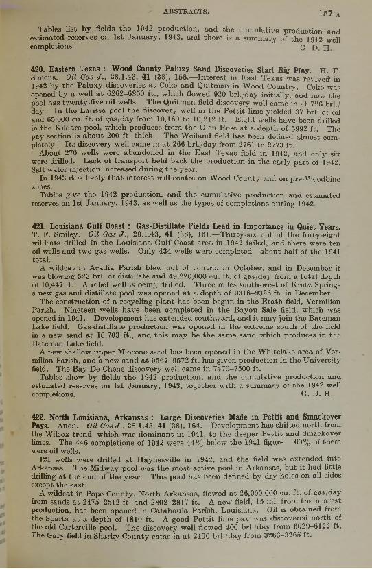
420. Eastern Texas : Wood County Paluxy Sand Discoveries Start Big Play. H. F.Simons. Oil Qas J ., 28.1.43, 41 (38), 158.— Interest in E ast Texas was revived in 1942 by the P aluxy discoveries a t Coke and Quitman in Wood Country. Coke was opened by a w ell at 6262-6350 ft., w hich flowed 920 brl./day initially, and now the pool has tw enty-five oil wells. The Quitman field discovery well came in at 726 brl./ day. In the Larissa pool the discovery w ell in the P ettit lime yielded 37 brl. of oil and 65,000 cu. ft. of gas/day from 10,160 to 10,212 ft. E ight wells have been drilled in the Kildare pool, which produces from the Glen Rose at a depth of 5992 ft. The pay section is about 200 ft. thick. The W eiland field has been defined alm ost com pletely. Its discovery well came in at 266 brl./day from 2761 to 2773 ft.
About 270 wells were abandoned in the E ast Texas field in 1942, and only six were drilled. Lack of transport held back the production in the early part of 1942. Salt water injection increased during the year.
In 1943 it is likely th at interest w ill centre on W ood County and on pre-Woodbine zones.
Tables give the 1942 production, and the cum ulative production and estimated reserves on 1st January, 1943, as w ell as the typ es of completions during 1942.
421. Louisiana Gulf Coast : Gas-Distillate Fields Lead in Importance in Quiet Years.T. F. Smiley. Oil Oas J ., 28.1.43, 41 (38), 161.— Thirty-six out of the forty-eight wildcats drilled in the Louisiana Gulf Coast area in 1942 failed, and there were ten oil wells and tw o gas wells. Only 434 w ells were com pleted—about half of the 1941 total.
A wildcat in Acadia Parish blew out of control in October, and in December it was blowing 523 brl. of distillate and 49,220,000 cu. ft. of gas/day from a total depth of 10,447 ft. A relief w ell is being drilled. Three miles south-west of Krotz Springs a new gas and distillate pool w as opened at a depth of 9316-9326 ft. in December.
The construction of a recycling plant has been begun in the Erath field, Vermilion Parish. N ineteen w ells have been com pleted in the B ayou Sale field, which was opened in 1941. D evelopm ent has extended southward, and it m ay join the Bateman Lake field. Gas-distillate production was opened in the extrem e south of the field in a new sand at 10,703 ft., and th is m ay be the same sand which produces in the Bateman Lake field.
A new shallow upper Miocene sand has been opened in the W hitelake area of Vermilion Parish, and a new sand at 9567-9572 ft. has given production in the U niversity field. The Bay De Chene discovery w ell came in 7470-7500 ft.
Tables show by fields the 1942 production, and the cum ulative production and estimated reserves on 1st January, 1943, together w ith a summary of the 1942 well completions. G. D. H.
422. North Louisiana, Arkansas : Large Discoveries Made in Pettit and SmackoverPays. Anon. Oil Gas J ., 28.1.43, 41 (38), 164.— D evelopm ent has shifted north from the Wilcox trend, w hich was dom inant in 1941, to th e deeper P ettit and Smackover limes. The 446 completions of 1942 were 44% below the 1941 figure. 60% of them were oil wells.
121 wells were drilled at H aynesville in 1942, and the field was extended into Arkansas. The Midway pool w as th e m ost active pool in Arkansas, but it had little drilling at the end of the year. This pool has been defined by dry holes on all sides except the east.
A wildcat in Pope County, N orth Arkansas, flowed at 26,000.000 cu. ft. of gas/day from sands at 2475-2512 ft. and 2802-2817 ft. A new field, 15 ml. from the nearest production, has been opened in Catahoula Parish, Louisiana. Oil is obtained from the Sparta at a depth of 1810 ft. A good P ettit lime pay was discovered north of the old Carterville pool. T he discovery w ell flowed 400 brl./day from 6029-6122 ft. The Gary field in Sharky County came in at 2400 brl./day from 3263—3265 ft.

1 5 8 a A B SÏB A O ÏS .
The 1942 production, and the cum ulative production and estimated reserves on 1st January, 1943, are tabulated by fields, together w ith a summary of the 1942 well com pletions. ' G D H
423. Rocky Mountain Area : Tensleep Production at Elk Basin Is Most Important Discovery of Year. T. R . Ingram . Oil O a sJ ., 28.1.43, 41 (38), 167.— 362 wells were com pleted in Colorado, W yom ing, and Montana in 1942, 115 fewer than in 1941. 226 found oil and seventy-six found gas. E leven discoveries were made from twenty- four im portant w ildcats, four being deeper horizons and three gas finds. All of the seven Colorado w ildcats were dry, and Montana had tw o oil and two gas finds out of six wildcats.
In the southern part of the E lk Basin field, W yom ing, deep production was found in the Tensleep. This excellent structure has given 11,000,000 brl. of light oil from shallow pays, and the Tensleep discovery m ay place it among the State’s largest black oil-fields.
A 580-brl. w ell was com pleted in the D akota at Horse Creek, but later it showed w ater. This w ell is on the north-west rim of the Denver Basin, and it m ay lead to w ildcatting in N orth-east Colorado. A deep Tensleep pay was opened in the Pilot B u tte field, and later an Embar discovery w as made.
A sm all W asatch w ell was com pleted in the North H iaw atha field.The m ost im portant discovery in Montana was a Madison lime producer on the
Twin R ivers structure north-w est of Cutbank. This made only 85 brl./day, but it opens up an area w ith favourable prospects.
Tables give the 1942 production, and the cum ulative production and reserves on 1st January, 1943, by fields, together w ith a summary of the 1942 completions.
G. D. H.424. Canadian Production at Peak. V. Lauriston. Oil Oas 28.1.43, 41 (38), 169.— Canada produced 10,359,267 brl. of oil in 1942. This is a record.
Turner V alley has been extended \ ml. to the north. I t has more than ninety undrilled w ell locations in proven territory, w ith good prospects of an extension of the productive area. Ten additional producers have been completed at Vermilion, which gave 66,720 brl. of oil in 1942.
A w ell a t Taber came in at 330 brl./day from a depth of 3181 ft. A n 80-brl. well has been brought in a t 3180 ft. a t Tilley.
T h e . p lant for recovering oil from the Athabaska tar sands has now been reconstructed.
Considerable new drilling is understood to have been done at Fort Norman, and35,000 brl. of oil were obtained in 1942, against 14,119 brl. in 1941. The construction of a pipe-line from Fort Norman to W hitehorse in the Yukon Territory has been considered.
Tables show the oil production b y fields in 1941 and 1942, th e number of wells producing in January and in December 1942, as w ell as a summary of the types of com pletions in 1942. H.
425. New Indiana Pools Small in Extent. Anon. Oil Oas J 28.1.43, 41 (38), 169.— N o im portant new oil-field was discovered by widespread w ildcatting in Indiana in 1942, although tw elve new fields and pay zones were opened, all of them in the south- w est'of the State. D evonian lime production was found in the Shelburn field, where five w ells came in for 150-200 brl./day each initially. In all other instances the results have been disappointing, only single-well pools resulting in m ost cases.
Much of th e 1942 developm ent was in the H azleton, Griffin, and Caborn fields. In terest in Trenton and sub-Trenton production in N orth-east Indiana increased throughout the year, and m any deep tests were under w ay at"the year end. Two m iles east of th e old Trenton gas-field tw o tests have found Trenton lime production. The w ells are 1 ml. apart, and gave 120 brl./day. In Adams County a deep test showed oil in the Jordan sand at 2261 ft. The Jordan sand lies w ell below the St J?©t0i*
Most of the proven acreage in the older fields has been developed and there are no prospects of increasing reserves in sight. Exploration in the near future will be m ainly in the south-w est and north-east. G- D . H.

ABSTRACTS. 1 5 9 a
426. Gas Discoveries Take Lead in Ohio. Anon. Oil Gas J ., 28.1.43, 41 (38), 170.__Most of the new pools and extensions in Ohio in 1942 were gas discoveries. The Clayton oil-field was extended i ml. north by a 55-brl. producer, and westward by three 100-brl. wells. I t m ay possibly join the old E ast Somerset field 2 ml. to the west. The small Thron pool has been extended J ml. to the south-east. There is a possibility of a southward extension of the H inckley gas-field. The Gaysport gas pool and the Clinton oil-pool were extended during 1942. A new Oriskany sand gas-field was opened in Guernsey County, but it is not expected to be large. No commercial production was found in sub-Trenton te s ts .. G. D. H.
427. The Nation’s Major Fields. W . Y. Howard. Oil Gas J ., 28.1.43, 41 (38), 171.— Over half of the U .S. oil output in 1942 came from fields giving more than 10,000 brl./day. Many of the production declines of the major fields reflect market and transport conditions, and th is is particularly noticeable in W est Texas. Of the thirty- seven fields listed as having recoverable reserves of more than 100,000,000 brl. of oil, only Hawkins is a recent discovery, and these fields possess more than half of the nation’s recoverable reserve.
California, Texas, and N ew Mexico are dependent on major fields, but Louisiana and Kansas get the bulk of their oil from medium-sized fields. Texas and New Mexico are the only States w ith more than half of their original reserves still underground.
Tables give the production of the seventy-five major fields in 1941 and 1942, the age, estim ated ultim ate, and remaining reserves. G. D. H.
428. December Completions Show Gain Over Previous Months. Anon. Oil Gas J .,28.1.43, 41 (38), 205.— 1454 w ells were com pleted in U .S.A . in December 1942, 101 more than in November. The Mid-Continent area led in the increased activity, Oklahoma, and K ansas having seventy-eight additional completions, w ith thirty-two more oil wells. 494 dry holes were com pleted during December, an increase of fifty- eight over November. California had th irty dry holes. Illinois suffered a decline of thirty-three completions.
A table summarizes th e operations in December 1942 by States, showing the total completions, numbers of oil, gas and dry wells, the footage, and the numbers of wells in various depth ranges. G. D. H.
429. Study Reveals Imperative Need for Increasing Nation’s Oil Reserves. H . J.Strath. Petrol. Engr, January 1943, 14 (4), 31.— In 1942 the U .S. crude oil production was only about 1% below th e 1941 figure; the refinery runs were about 5% lower than in 1941. In 1943 it is expected th at 1,475,000,000 brl. of crude will be required compared w ith the 1,385,000,000 brl. produced in 1942. The indications are that not only is the new oil discovery rate insufficient to offset the heavy w ithdrawals from underground reserves, but the available supplies are being used 22% faster than under the efficient rate of utilization realized in peace-time.
The known U .S. oil reserves have fallen by more than 3,000,000,000 brl. since 1938, and the reserve additions in 1942 were only 55% of that year’s production. While the number of w ildcats drilled in 1942 w as alm ost the same as in 1941, the number of dry holes was 30-6% of th e to ta l, against 22-2% in 1941. The total number of wells was 48% below the 1941 figure. The oil demand is now three and a half times the demand during th e last war, w hen 118,000 brl. of oil were found per dry hole drilled, whereas the corresponding figure for 1941 was 60,000 brl., and for 194249,000 brl.
Crude oil prices were practically stationary during 1942, w hen production fell in Texas, Louisiana, Oklahoma, Illinois, and N ew Mexico, while it rose in Kansas, California, Arkansas, and the E astern States. Illinois had a 61% decline in com pletions and Oklahoma a 57% decline. Texas provided 35% of the nation s 3100 wildcats, and these formed 22% of th at S tate’s completions. Illinois had 18% of the nation’s w ildcats, w hich constituted 30% of that S tate’s 1942 completions. Only 125 wildcats were drilled in California last year, whereas there should have been twice that number had m aterials been available. Throughout the nation there were 442 successful w ildcats which added 750,000,000 brl. of new reserves.

1 6 0 a ABSTRACTS.
W hile the demand for gasoline fell by 67,875,000 brl. in 1942, the fuel oil demand rose b y 53,963,000 brl.
In 1938 the discoveries reached a peak of 1,650,000,000 brl., giving total reserves of 21,813,000,000 brl. a t the-beginning of 1939, but the reserve was only 18,586,000,000 brl. a t th e beginning of 1943, for the average annual discoveries since 1938 have been only about 500,000,000 brl. Since 1935 the ratio of discoveries to production has declined steadily. The number of dry holes drilled per 1,000,000 brl. of new oil discovered has increased nearly nine-fold since 1935, and th e reserves in terms of years’ supply have fallen from 191 years in 1935 to 12-6 in 1943. In 1935 the average cost per exploratory w ell w as about $31,000 and the cost per barrel of new oil was 13-3 cents, w hile it took 4-3 exploratory w ells to find 1,000,000 brl. of new oil. In 1937 th e cost was 6-3 cents/brl. of new oil, but in 1942 the cost/brl. of new oil was 37-6 cents and the average cost per exploratory w ell was $47,000, eight exploratory w ells being required to find 1,000,000 brl. of new oil.
There are eight diagrams and eleven tables giving statistics. G. D. H.•
430. Wildcat Drilling in California. W. A . Sawdon. Petrol. Engr, January 1943, 14 (4), 100.— L ast year a few sm all fields were discovered in California, and extensions were m ade to som e old fields. Production increased and drilling decreased. Many shallow w ells were drilled in proved areas to increase the supply of heavy oil. The light-oil production is not y e t a t its maxim um effective recovery rate, and careful gas conservation is being practised in the light-oil production. D epleted oil-fields are being used to store excess summer-gas production for use in the winter.
During the period 1939-1942 the discovery of new fields and the extensions to proved areas were not enough to m aintain the known reserve. The number of exploratory w ells declined in this period, and was restricted last year by material shortages as w ell as by economic factors.
The R iverdale field, discovered at the end of 1941, came in at 6665-6685 ft. for 558 brl./day of 34° A .P .I. crude, w ith 1,375,000 cu. ft. of gas. Lower zones tested w et. The W illiams field gave 1725 brl./day bf 16-5° A .P .I. oil from 2340 ft. in the discovery well which later w ent over to water. The W illiams field is a sharp anticline w ith a productive area of less than 1000 acres. The deeper zones, such as the W agon W heel and the Eocene, have not y e t been tested.
The A naheim -Buena Park area discovery w ell came in at 9660 ft. Two w ells have been com pleted, but one is giving much water. The Palom a field has been extended 1 ml. to the north by a w ell w hich gives 34-4° A .P .I. oil instead of 50-55° A .P .I. oil as in th e high gas-o il ratio area.' The new w ell was drilled to 11,043 ft. The Aliso Canyon field has been extended to the w est by a 9086-ft. w ell, of w hich the initial production w as estim ated to be 2393 brl. of oil/day w ith more than 1,000,000 cu. ft. of gas. The oil is from the upper Lusian rock w ith closure against a fault.
A new field m ay have been found east of the Strand field. The discovery well was drilled to 8207 ft., and initially gave 1553 brl./day of oil and 1,250,000 cu. ft. of gas. Very heavy oil was found on the R ancho Corral de Quatti, north of Los Olivos, and this oil has to be thinned w ith distillate to permit pumping it to the surface. The structure is anticlinal w ith the oil in fractured siliceous shales (Miocene).
T he Bowerbank field discovery w ell produced 11,000,000 cu. ft. of gas/day from 4253-4262 ft. G. D. H.
431. Future Development of North-west Wilmington Field. W. R. Cabeen and A. L. H unter. Oil Qas J ., 4.2.43, 41 (39), 60.— Marked changes in stratigraphy in going from the W ilm ington field north-w est towards Torrance, coupled w ith complicated faulting and flattening of the structure, influence the am ount of vertical and horizontal oil saturation in the N orth-w est W ilm ington field. Therefore the possible recovery from each part of th e area m ust be estim ated separately. B lock A, the m ost north-westerly fault block, has 136 ft. of producing sand in the Ranger and Terminal zones, each of w hich has an average porosity of 15% and an average saturation of 75%. B lock B , the n ext fault block to th e south-east, has 467 ft. of producing sand in all, w ith similar porosities and saturations to Block A. Block C, still farther to th e south-east, has 90 ft. of producing sand in the main Tar zone, which has an average porosity of 30% and a saturation of 85%. The Terminal and Ranger
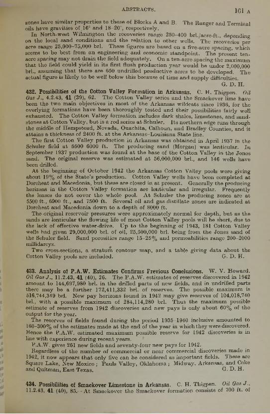
ABSTRACTS. 161 A
zones have similar properties to those of Blocks A and B. The Ranger and Terminal oils have gravities of 16° and 18-20°, respectively.
In North-west W ilm ington th e recoveries range 250-400 brl./acre-ft., depending on the local sand conditions and the relation to other wells. The recoveries per acre range 25,000-75,000 brl. These figures are based on a five-acre spacing, which seems to be best from an engineering and economic standpoint. The present ten- acre spacing m ay not drain the field adequately. On a ten-acre spacing the maximum that the field could yield in its first flush production year would be under 2,000,000 brl., assuming th at there are 650 undrilled productive acres to be developed. The actual figure is likely to be well below this because of time and supply difficulties.
G. D . EL432. Possibilities of the Cotton Valley Formation in Arkansas. C. H. Thigpen. Oil Gas J ., 4.2.43, 41 (39), 62.— The Cotton V alley series and the Smackover lime have been the tw o main objectives in m ost of the Arkansas wildcats since 1936, for the overlying formations have been thoroughly tested and their possibilities fairly well exhausted. The Cotton V alley form ation includes dark shales, limestones, and sandstones at Cotton Valley, but is a red series a t Schuler. Its northern edge runs through the middle of H em pstead, N evada, Ouachita, Calhoun, and Bradley Counties, and it attains a thickness of 2400 ft. a t th e Arkansas-Louisiana State line.
The first Cotton V alley production in Arkansas was obtained in April 1937 in the Schuler field at 5500-6000 ft. The producing sand (Morgan) was lenticular. In September 1937 production w as found at the base of the Cotton Valley in the Jones sand. The original reserve was estim ated a t 56,000,000 brl., and 146 wells have been drilled.
At the beginning of October 1942 the Arkansas Cotton Valley pools were giving about 19% of the S tate’s production. Cotton Valley w ells have been completed at Dorcheat and Macedonia, but these are closed in at present. Generally the producing horizons in the Cotton V alley formation are lenticular and irregular. Frequently the lenses do not cover th e w hole pool. A t Schuler the producing zones are at 5500 ft., 6900 ft., and 7500 ft. Several oil and gas-distillate zones are indicated at Dorcheat and Macedonia down to a depth of 8000 ft.
The -original reservoir pressures were approxim ately normal for depth, but as the sands are lenticular the flowing life of m ost Cotton Valley pools will be short, due to the lack of effective water-drive. U p to the beginning of 1943, 181 Cotton Valley wells had given 29,000,000 brl. of oil, 25,500,000 brl. being from the Jones sand of the Schuler field. Sand porosities range 15-25% and permeabilities range 200-2000 millidarcys.
Two cross-sections, a stratum contour map, and a table giving data about the Cotton Valley pools are included. G. D. H.
433. Analysis of P.A.W. Estimates Confirms Frevious Conclusions. W. V. Howard. Oil Gas J ., 11.2.43, 41 (40), 26.-—The P.A .W . estim ates of reserves discovered in 1942 amount to 144,697,980 brl. in the drilled parts of new fields, and in undrilled parts there m ay be a further 172,411,332 brl. of reserves. The possible maximum is 516,744,349 brl. N ew pay horizons found in 1942 m ay give reserves of 104,018,740 brl., w ith a possible m axim um of 284,114,280 brl. Thus the maximum possible estimate of reserves from 1942 discoveries and new pays is only about 60% of the output for the year.
The reserves of fields found during the period 1935-1940 inclusive amounted to 160-300% of the estim ates made at the end of the year in w hich they were discovered. Hence the P.A.W . estim ated m axim um possible reserve for 1942 discoveries is in line w ith experience during recent years.
P.A.W . gives 261 new fields and seventy-four new pays for 1942.Regardless of the number of commercial or near commercial discoveries made in
1942, it now appears th at only five can be considered as important fields. These are Square Lake, New Mexico ; Pauls Valley, O klahom a; Midway, Arkansas, and Coke and Quitman, E ast Texas. G. D. H.
434. Possibilities of Smackover Limestone in Arkansas. C. H . Thigpen. Oil Gas J .,11.2.43, 41 (40), 85.— A t Sm ackover th e Smackover formation consists of 700 ft. of
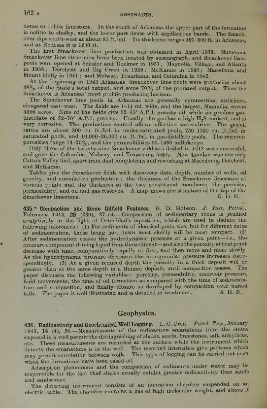
1 6 2 a ABSTRACTS.
dense to oolitic limestone. In the south of Arkansas the upper part of the formation is oolitic to chalky, and the lower part dense w ith argillaceous bands. The Smackover dips south-w est a t about 85 ft./m l. Its thickness ranges 450-900 ft. in Arkansas, and at R odessa it is 1230 ft.
T he first Smackover lime production w as obtained in April 1936. Numerous Sm ackover lime structures have been located by seismograph, and Smackover lime- pools were opened at Schuler and Buckner in 1937 ; Magnolia, Village, and Atlanta in 1938; Dorcheat and B ig Creek in 1939; M cKamie in 1940; Macedonia and M ount H olly in 1941; and Midway, Texarkana, and Columbia in 1942.
A t the beginning of 1943 Arkansas’ Smackover lime pools were producing about 48% of th e S tate’s to ta l output, and some 70% of the prorated output. Thus the Smackover is A rkansas’ m ost prolific producing horizon.
The Smackover lime pools in Arkansas are generally sym metrical anticlines, elongated east-w est. The fields are 1—1 £ ml. wide, and the largest, Magnolia, covers 4500 acres. N ine of the fields give 32-45° A .P .I. gravity oil, while six produce gas- distillate o f 52-70° A .P .I. gravity. U sually the gas has a high H 2S content, and is very corrosive. The production control allows effective water-drive. The gas/oil ratios are about 300 cu. ft./brl. in under-saturated pools, 750-1250 cu. ft./brl. in saturated pools, and 10,000—30,000 cu. ft./brl. in gas-distillate pools. The reservoir porosities range 14-20% , and th e permeabilities 50-1500 millidarcys.
Only three of the tw enty-nine Smackover w ildcats drilled in 1942 were successful, and gave the Columbia, Midway, and Texarkana fields. N ew London was the only Cotton V alley find, apart from dual completions and reworking at Macedonia, Dorcheat, and McKamie.
Tables give the Smackover fields w ith discovery date, depth, number of wells, oil gravity, and cum ulative production; the thickness of the Smackover limestone at various points and the thickness of the tw o constituent m em bers; the porosity, perm eability, and oil and gas reserves. A map shows th e structure of the top of the Smackover lim estone. • G. D . H .
435.* Compaction and Some Oilfield Features. G. D . Hobson. J . Inst. Petrol., February 1943, 29 (230), 37-54.— Compaction of sedimentary rocks is studied analytically in the light of Ortenblad’s equations, which are used to deduce the follow ing inferences : (1) For sedim ents of identical grain size, but for different rates of sedim entation, those being laid down m ost slowly will be m ost compact. (2) A fter sedim entation ceases the hydrodynamic pressure at a given point— i.e., the pressure com ponent driving liquid from the sedim ent— and also the porosity a t that point decrease w ith tim e, com paratively rapidly at first, And then more and more slowly. A s the hydrodynamic pressure decreases the intergranular pressure increases correspondingly. (3) A t a given reduced depth the porosity in a thick deposit will be greater than at the same depth in a thinner deposit, until compaction ceases. The paper discusses the following variables : porosity, permeability, reservoir pressure, fluid m ovem ents, th e tim e of oil formation as compared w ith the tim e of sedim entation and com paction, and finally closure as developed b y compaction over buried hills. The paper is w ell illustrated and is detailed in treatm ent. A. H . N.
Geophysics.436. Radioactivity and Geochemical Well Logging. L. C. Uren. Petrol. Engr, January 1943, 14 (4), 50.— Measurements of the radioactive emanations from the strata exposed in a well permit the distinguishing of shales, sands, limestones, salt, anhydrite, etc. These measurem ents are recorded at the surface while the instrument which d etects the em anations is in the well. The recorded intensities give patterns which m ay permit correlation betw een w ells. This typ e of logging can be carried out even w hen the formations have been cased off.
Adsorption phenomena and the compaction of sedim ents under water may be responsible for the fact th a t shales usually exhibit greater radioactivity than sands and sandstones.
T he detecting instrum ent consists of an ionization chamber suspended on an electric cable. The chamber contains a gas of high molecular w eight, and above it
ABSTRACTS. 1 6 3 a
is an amplifier. Current flows in the circuit only when the ionization chamber is influenced by radioactive em anations, and the current is proportional to the emanation intensity. In making the log the instrum ent is drawn upwards from the bottom of the well.
The recorded variations in the lateral position of the radioactivity profile are only relative, and lack quantitative significance. Low radioactivity is shown by sand, sandstone, or lim estone, w hile clay and shale give a high intensity. The logs do not indicate the porosity and perm eability of the rocks or the nature of the fluids the rocks contain, although the indication of clay or shale naturally implies low permeability. Thin clay streaks can easily be detected, and unconformities and faults may be shown. The position of the bottom of the casing or of the cem ent plug is clearly shown. Open hole logs give rather better differentiation and more detail than logs from cased holes. The presence of fluid in the w ell does not affect the logs. Possible oil-sands can be detected behind casing, and this feature is useful for wells drilled before electrical logging w as introduced. W ell logs m ay be checked.
In neutron logging the form ations are bombarded w ith neutrons generated from radioactive material in the surveying instrum ent, and the intensity of the gamma rays so produced is measured by an ionization chamber above the part of the instrument carrying the radioactive material. The m ethod m ay be able to show the porosity and the fluid content of the rocks, for hydrogen nuclei have a special action on the neutrons.
Delicate m ethods of chemical analysis allow the presence of minute amounts of hydrocarbons, hydrogen, etc ., in rock sam ples to be determined quantitatively, and on plotting the values so obtained against a depth scale, a geochemical w ell log results. Often the patterns are characteristic, and th ey m ay indicate the presence of oil or gas accumulations in underlying or nearby beds. Thus the probable success or failure of a well can often be predicted before it is completed.
Within geological tim e slow migration of hydrocarbons has occurred through the beds overlying oil deposits. Thus even surface soil m ay show minute amounts of hydrocarbons. System atic soil analyses m ay show a “ halo ” of hydrocarbons around an oil deposit. In geochem ical w ell logging the sampling intervals depend on the detail required, but are com m only about 30 ft. Cores or drill cuttings may be used. A complete analysis gives hydrogen, to ta l hydrocarbons, m ethane, m ethane- butane, pentane-decane, carbonate, sulphate, halides, and acid-soluble sand. The source of the hydrogen is uncertain. The m ethane m ay not be from an oil accumulation. The hydrogen m axim um on th e logs generally occurs above the oil, commonly several hundred to 1000 ft. above, and then the amount of hydrogen diminishes rapidly nearer the oil. The to ta l hydrocarbons increase w ith depth, and show a rapid rise as th e oil is approached. W hen oil is present the pentane-decane content is h igh ; when gas alone is present the content of methane—butane is high. The advance indications of th e presence or absence of oil or gas facilitate completion planning, and prevent premature abandonment. D ry holes generally give low hydrocarbon values. I f th e w ell is off-structure th e hydrocarbon values show a maximum and then decrease at greater depths. G. D. H.
437.* The S.P. Dipmeter. H . G. D oll. Petrol. Tech., January 1943, 6 (1), A.I.M.M.E. Tech. Pub. No. 1547, 1-10.— The S.P. dipm eter consists of three electrodes set 120° apart in a horizontal plane w hen th e instrum ent is vertical, and connected through separate insulated conductors to potentia l measuring devices at the surface, w ith the circuit closed through th e earth and a ground electrode. Above the electrodes, and always in the same relative position, is th e photoclinom eter, consisting of a compass needle and a ball free to set in its equilibrium position on a graduated glass of known curvature. A camera is so situated th at it photographs the needle, ball, and a marker showing the position of one of th e electrodes.
When a formation is not bedded in planes at right angles to the axis of the borehole, the three S.P. curves obtained sim ultaneously w ill be substantially alike in form, but not alike as regards the depths of particular features. These depth discrepancies correspond to, and are a measure of the dip of the boundary plane separating two beds, and coupled w ith th e orientation of the electrodes and the inclination of the well as shown by the photoclinom eter, provide data whereby the dip and the strike of the beds can be calculated or determined on a special instrument.
1 6 4 a ABSTRACTS.
Normally the dipm eter-photoclinom eter is lowered in the hole to 10-15 ft. below the desired section, th e S.P. curves being observed all the w ay down, to make sure of the m ovem ent of the instrument. The latter is then pulled up to about 3 ft. below the section, stopped, and after allowing the instrum ent to settle, a picture is taken by the photoclinom eter. W hen th is has been done, the section is surveyed by the three dipm eter electrodes. A t th e upper end of the section a second photo- clinometer picture is taken to find w hether the instrum ent has rotated while being pulled upwards. A series of observations of th is typ e can be taken in a single run.
A n exam ple of an actual m easurem ent is given in detail.Dip m easurem ents can be made in the above manner cheaply, easily, and quickly.
Good results are obtained w ith dips over 10°, and fair results w ith dips between 5° and 10°. The measurem ents are valuable in perm itting the detailing of structures, and are very useful in the investigation of salt dome structures. G. D . H.
438.* Use of Neutron Curves. A. B. W inter. Oil W kly, 25.1.43, 108 (8), 20.—The neutron typ e of radioactivity well logging measures the effect of the bombardment of the form ations by neutrons from a strong source. Neutron logging seems to be of value as a companion curve to the gamm a-ray logging, and used alone to solve certain subsurface problems regarding the form ations behind casing. The effect of the neutron bombardm ent is measured in an ionization chamber situated above the neutron source. The source of neutrons in th e logging instrum ent is a mixture of radium and beryllium, and m ost of the neutrons are fast and penetrating. The neutrons are able to pass through m any inches of iron w ithout much loss, and they are slowed down m ainly by the hydrogen present in the rocks.
The logging device is connected by cable to recording apparatus at the surface, and the average surveying speed is 1000 ft./hour. Satisfactory logs can be made w ith or w ithout fluid in the hole, but th e position of the liquid level relative to the zone of interest should be known accurately, for the presence or absence of liquid in the hole shifts the curve as a w hole. D ense limestones or hard sandstones give high in tensity values on the curve. Oil or water in the pores shows the occurrence of porous zones in lim estones or in clean sandstones by giving low intensities. Shales also g ive low intensities generally, due usually to the greater am ount of hydrogen in the shale, either as connate or chemically combined water. Consideration of gamma- ray and neutron logs together perm its shales to be detected by their high gamma-ray intensities and low neutron log intensities. The position of th e casing seat is usually shown clearly on neutron logs.
A neutron and a gamma-ray log are given, together w ith the corresponding well log. " G. D . H.
Drilling.439.* Making the Most of Drilling Materials. J. S. M ontgomery. Oil W kly, 7.12.42, 108 (1), 14-16. P aper Presented before Am erican Association of Oilwell Drilling Contractors.— The paper describes, in a general manner, precautions to be taken with drilling equipm ent and m ethods of m aintaining them for longest use under efficient conditions. The life of drill-pipe varies w ith areas in which it is used, as some areas encounter formations w hich develop a very corrosive fluid, and the drill-pipe deteriorates before the tool-joints are worn out. Other w ells encounter abrasive formations in which the tool-joints are worn and the drill-pipe is in good condition. There are services com panies making satisfactory internal inspection of drill-pipe to advise w hen joints of pipe should be laid down or the entire string laid down. Experience indicates that th is service has been satisfactory. W here pipe is worn out from corrosion, tool-joints should be salvaged and used on other pipe. I t would appear that a programme w ould be m ost applicable w hereby tool-joints in corrosive areas would be transferred to pipe used in abrasive areas, thus reducing the requirement of purchasing new tool-joints. I t is, of course, appreciated that som e typ es of tool-joints are not salvageable. The outside wear of tool-joints has given a great deal of concern to rotary operators, and reports are made of the building up of tool-joints by welding on a hardening material. H owever, it seem s th at the m ost practical m ethod to-day is to apply a sleeve to the tool-joint. Where tool-joint threads are worn and the body of the joints is still in good condition, it is very practical to turn new threads. U n

aívo íx IACTS. 1 6 5 A
even wear on tool-joints m ay be attributed to crooked drill-pipe. Above all other things, an operator should be very careful in seeing that his drill-pipe is straight at all times, or he may expect undue wear which w ill be first noticeable by uneven wear on the pipe and the tool-joints.
There has been som e experience in building up and in re-sleeving drill-collars. However, this experience so far leaves som e question as to its success. Where bits have not been badly worn, and their hearings are in good condition, there is every reason to have them re-tipped, as they have proved satisfactory in m ost operations. The greatest care that can be exercised on th e kelly joint is to see th at it is straight at all times and properly handled in m oving from one location to another. A. H . N.
440.* Improved Casing Recovery Method Reduces Cost. W. L. Baker. Oil W kly,21.12.42,108 (3), 16.— The m ethod consists of making a series of cuts at pre-determined intervals w ith one trip into the well, then going in w ith a washover string and recovering each section of cut casing w ithout withdrawing the string from the hole. When the recovered casing is being removed, the washover pipe is suspended from slips, and the casing is withdrawn through it. This m ethod of recovering casing from dry holes has the following advantages over m ethods formerly used : (1) Rig time spent in breaking down and picking up the wash pipe is very greatly reduced. (2) Rig time is further reduced by making all the cuts before washing operations are started.(3) The rental on wash-pipe and special tools is reduced through decreased rig time.(4) There is less expense of conditioning m ud due to the smaller number of trips into the hole and the shorter tim e required for the entire operation. (5) More casing can be recovered at a cost equivalent to or less than the value of the casing.
Examples are given for five w ells where the m ethod was used. The procedure recommended m ay be summarized as follows : (1) Select as large an interval between cuts as is feasible, taking into account the quantity of wash-pipe available and the clearance between the casing collars and the original walls of the hole. An interval up to 1000 ft. for 5i-in . casing and up to 500 ft. for 7-in. casing is suggested. (2) Run a cutting tool and cut the casing a short distance above the theoretical top of the cement. Make additional cuts progressively upward at the predetermined interval. (3) Make up the string of wash-pipe slightly longer than the interval between cuts, run an overshot between the top and the n ext to top joint. (4) W ash over the casing until the overshot will latch over the top collar. Then pull the pipe up until the overshot is above the rotary table, break th e joint betw een the overshot and the balance of the wash-pipe, and set the wash-pipe on slips. (5) Pull the casing through the wash- pipe, break it out and lay it down, then screw the top o f the wash-pipe back on the overshot, and proceed to w ash over the next section of casing. A. H. N.
441.* Progress in Drilling. Anon. Oil Oas J ., 31.12.42, 41 (34), 142.— The paper is written in English and Spanish, and reviews drilling practices in 1942. One of the principal advances in drilling concepts during th e past year was the increasing im portance placed on the necessity of drilling the bore-holes to gauge. I t has become increasingly evident over the past few years th at m any of the major troubles of drilling and production operations have been due to this factor. For instance, investigation in one case of a deep well, w hich was bothered extensively by tw is toffs a t 2000—2700 ft., showed that washouts of the hole in th is interval were allowing the drill-pipe to assume an eccentric and whipping m otion. Mud conditioning to prevent erosion and dissolving of the shale in th is section elim inated twistoffs.
Troubles w ith casing failures have on numerous occasions been due to this cause. This is principally due to the fact th at w hen the cem ent was placed back in the pipe, the presence of a cavity allowed the cem ent to channel. I t has also been found that there was sufficient cavitation of the formations to affect greatly the height of the cenjent behind the pipe.
Mud problems are reviewed in some detail. The greatest advance in the handling of drilling fluid, and one of major im portance as far as drilling in general is concerned, has been the developm ent during the past year of a satisfactory treatm ent for the reduction of the water loss and filter-cake in salt-water contam inated fluids. The main ingredient required is an organic colloidal material. The material (Impermex) is a special organic colloid which is added to the drilling fluid containing salt. The salts (calcium, magnesium, sodium) in the fluid are a partial preservative, but it is necessary to add other chemicals to prevent growth of organisms which will cause the
0

1 6 6 a ABo iiv a u io .
m ud to lose some of its desirable properties. The application of this material and the results to be obtained w ith it have been known for a number of years, but there were numerous details concerned w ith its use w hich were not thoroughly understood. One of these w as th e souring or ferm entation of th e drilling fluid. The hydrolyzed starch m aterial would be added, and the desired results obtained. After a few days th e w ater loss would again increase and the drilling fluid would get steadily worse. I t was found th at bacterial action caused ferm entation— som ething not formerly experienced w hen using inorganic drilling fluids.
N ow th a t th e ferm entation can be prevented by addition of recently developed preservative chemicals, it is possible to take a salt-water drilling fluid w ith a water loss of 150 c.c., treat it w ith the organic compound, and bring the loss down to 10- 12 c.c. I t can be brought even lower if desired. From 2-5 lb. of the commercial m aterial barrel of drilling fluid is the am ount used. The cost of the material is reasonable in v iew of the results obtained.
Slim-hole drilling and multiple-zone com pletion are reviewed. A t the end of the paper the interesting m ethod of disintegrating mud cake— which is found to be negative ly charged— by applying electricity to it, through the use of casing as an electrode, is briefly discussed. A. H. N.
442.* Electrical Logging to Determine Character of Formations. L. C. Uren. Petrol. Engr, Decem ber 1942, 14 (3), 46.— The developm ent of electrical logging methods is first given. R esistiv ity measurements are then discussed. In comparing the electrical properties of rock strata exposed in the w all of a well, a system of electrodes, lowered into the w ell from the surface on a multi-conductor cable, is employed as a m eans of establishing a flow of electricity into each stratum, whereas the relative conductivities of different beds are determined by measuring the inverse values of their relative resistivities. The electrode system usually comprises three electrodes suspended at different depths, a few feet apart. One electrode is used as a means of passing direct current through the intervening well fluid into the surrounding strata. The other tw o electrodes, connected through a potentiom eter at the surface, record a certain difference in potential which, considered in relationship to the spacing of the electrodes, the temperature, and the conductivity of the w ell fluid, indicates the resistivity of the formation im m ediately surrounding the input electrode.
The electrode system is slowly lowered into the w ell, and a continuous record showing variation in resistivity as indicated on the potentiom eter is autom atically recorded on photographic film in the form of a profile on a depth-scale that can be directly compared w ith a driller’s graphic log of the well. Values of resistivity are expressed in ohm s/eu. m. of rock mass, and range from as little as one to several thousand ohms, depending on the electrical conductivity of the material. The factors influencing the conductivity are discussed.
W hen a liquid is forced through a porous solid medium, a difference in potential betw een tw o points in the porous solid is observed. Thus, drilling fluid filtering through the porous rock strata exposed in the w all of a w ell develops an electro- filtration effect th at creates an electro m otive force th at m ay be measured by the single-electrode circuit described. Also, an electro-m otive force is generated whenever tw o different electrolytes come into contact in water solution in a porous medium : as w hen drilling fluid enters a permeable stratum from the w ell and develops contact w ith the native fluid in the formation. The electro-m otive force developed increases as th e interfacial surface of the fluid in contact increases, and inasmuch as th is interfacial surface of contact increases w ith the depth of penetration of the drilling fluid into the form ation, it follows that a greater electro-osm osis effect is developed in highly permeable strata than in those less so. Electro-filtration e.m .f. and electro-osmosis e.m .f. both result from migration of drilling fluid into the w all rocks, and, as migration occurs more readily and to a greater degree in highly permeable strata than in those less so, it follows th at the observed values of the self-potential generated become a measure of th e relative permeabilities of the form ations th at give rise to them .
The equipm ent of electrical logging, together w ith the application and interpretation of this m ethod, are discussed a t length.
In discussing the future of the m ethod, Prof. Uren points out th at the art of electrical logging is young and m any opportunities for its further developm ent and application doubtless still exist. U p to th e present tim e, electrical logs have been used primarily

ABSTRACTS. 1 6 7 A
in making relative comparisons of rock properties. The data have been regarded as having only qualitative value. Y et it would seem th at the resistivity and selfpotential records should have quantitative significance, and th at if we had sufficient information, or understood them w ell enough, we could begin to interpret them in terms of actual sand perm eability, porosity, oil or water content. Perhaps, also, they will find new applications, as in determining the depth of penetration of drilling fluids, the effective thickness of clay w all-sheaths, proxim ity of wells to edge-waters, location of unconformities, gas-oil interfaces in gas-cap areas, etc. A new methqd of obtaining electrical records while drilling is in progress, by making the logging equipment a part of the regular drilling “ string,” has been proposed and partly developed. Present methods of electrical logging are applicable only in open hole, but some way of procuring resistivity and self-potential records through casing or outside of casing may yet be developed, using perhaps more com plex circuits in which the casing plays a part— such as th at em ployed by the “ stratagraph.”
Twenty-nine references are appended. A. H. N .
443>. Directional Redrilling of Piercement Type Dome to Increase Recovery. J. Zaba. Oil Gas J ., 14.1.43, 41 (36), 31-33.— The m ethod of directional drilling of wells for oil is studied. The practical application of the m ethod m ay be divided into three groups. The first group includes cases in w hich directional drilling is used as an emergency measure. The best exam ple of th is application is directional drilling of a relief well to control a burning or a cratered well. The second group covers application of directional drilling as a developm ent measure. In th is group would be included drilling of multiple w ells from one surface location, completing of a well under an inaccessible location from a satisfactory surface location, drilling in highly faulted areas, and other similar cases. The third group comprises application of directional drilling for the purpose of securing additional oil recovery from apparently drilled-out properties. In this application directional drilling is used w ith particular success in the old piercement-type salt-dom e fields of the Gulf Coast. Considerable additional recovery is being obtained in th is area in fields which were considered as drilled out with normal developm ent m ethods.
Directional re-drilling of a property appears to violate the generally accepted concept of advantages of w ide spacing. I t should be remembered, however, th at a re-drilling campaign, to be econom ically successful, can be applied only in special cases, and that piercem ent-type dome oil-fields constitute just such a special case. The producing area of such fields is usually a narrow rim surrounding the salt mass. Steep dips, faulting, and abrupt lateral changes of the lithological character of the producing formations m ake the location of the bottom of the well of primary im portance. Conditions encountered are illustrated by the case of a well drilled in one of these fields. The problems to be studied are explained. A. H . N .
444.* Effects of Certain Gums and Starches on Filtration of Salt-Water Muds at Elevated Temperatures. F . Perkins and B . C. Craft. Petrol. Tech., January 1943, 6 (1), A.I.M.M.E. Tech. Pub. N o. 1551, 1-4.— I t is im portant to control filtration or water loss from drilling m uds, for th is affects th e analyses bf side-wall cores, the interpretation of electric logs, and the am ount of cem enting needed. Salt-water and/or high temperatures seriously affect th e filtration characteristics by increasing water loss, a trouble which can be reduced by adding starches and gums to the muds. In testing the effects of adding gum s and starches th e viscosities were measured in a Stormer instrument at 600 r.p.m ., and water loss in a Baroid wall-building tester at 80-250° F. under a pressure of 500 lb ./in .2 for 30 min. The mud was formed of 150 gm. of commercial Louisiana mud, 50 gm . of salt and 300 gm. of tap water. Gelatinized starch (1% caustic soda, 10% dry starch and 89% water) or gum was added with stirring to give a m ud viscosity of about 50 centipoises. In the fermentation tests germicides such as trichlorophenol and pentachlorophenol were added.
The most favourable am ounts of gum karaya, gelatinized starch, commercial starch, and gum ghatti (0-25%, 1-0%, 1-5%, and 1-0% respectively) gave filtration rates less than a quarter of those for the untreated muds, and w ith a much smaller increase of water loss w ith rise in tem perature. The effectiveness of the two starches increased greatly above 175° F . Gum -treated samples had much better filter cake textures than those treated w ith starch. The addition of more than 0-25% of gum

1 6 8 a ABSTRACTS.
karaya gave very high viscosities. More than 1-5% of commercial starch markedly increased th e m ud viscosity.
Gums karaya and ghatti had slight ferm enting tendencies, while muds with commercial starch ferm ented under all conditions except w hen germicides were added. Commercial starch seem s best for field use since gums are too expensive under present conditions. Germicides should alw ays be added except w ith gelatinized starch in highly alkaline muds. G. D. H.
445. Patents on Drilling. A. G. Bodine. U .S .P . 2,304,793, 15.12.42. Appl. 9.6.41.—M ethod and apparatus for cutting pipe.
D . G. C. Hare. U .S .P . 2,304,910, 15.12.42. Appl. 29.5.40. Determination ofspecific gravity of fluids w hilst passing through containers, such as pipes, etc.
W . L. Church and R . R . Crone. U .S.P . 2,305,062, 15.12.42. Appl. 9.5.40. Cementing p lug for well-casing.
A. P . Heldenbrand. U .S .P . 2,305,079, 15.12.42. Appl. 10.9.38. Pipe-thsead cleaner w ith rotating brush.
H. W . Sitton and T. H . Sitton. U .S .P . 2,305,200, 15.12.42. Appl. 25.2.41. Drilling tool w ith tw o drills, one solid and the other tubular.
M. M. K inley. U .S .P . 2,305,261, 15.12.42. Appl. 23.11.40. Method of removing pipe from wells.
P . W . Lange and H . A. McFarland. U .S.P . 2,305,624, 22.12.42. Appl. 22.4.39.Power-driven pipe-tongs.
G. D . Johnson. U .S .P . 2,305,709, 22.12.42. Appl. 8.7.40. Releasable pin tap for engaging in an object in wells.
R . E . W iley. U .S .P . 2,305,944, 22.12.42. Appl. 23.9.40. Inclination indicating device having a suspended marking elem ent capable of universal m ovem ent and clock mechanism.
A. J . Penick and K . T. Penick. U .S.P . 2,306,102, 22.12.42. Appl. 17.2.41. Casing head.
A . H . Graham. U .S.P . 2,306,118, 22.12.42. Appl. 20.3.41. Earth-boring device having a tool w ith cutting flights of different diameters.
S. W. Long. U .S .P . 2,306,130, 22.12.42. Appl. 27.3.40. Well-drilling apparatus having bushings w ith central openings for th e drill pipe.
L. R . Brown. U .S .P . 2,306,368, 29.12.42. Appl. 25.6.40. Cementing tool for oil-w ell cem enting.
D . D . Anderson. U .S .P . 2,306,369, 29.12.42. Appl. 22.9.41. Coring apparatus w ith a central core-barrel.
W . B . N oble and J . F . Shaw. U .S .P . 2,306,491, 29.12.42. Appl. 15.6.40. Corebit w ith rotary cutters.
W . B . Noble. U .S .P . 2,306,492, 29.12.42. Appl. 23.11.40. Reamer in a well-forming tool.
P . Talm ey. U .S .P . 2,306,509, 29.12.42. Appl. 2.10.39. Gas detector using heated wires covered w ith catalysts.
M. D . Carleton. U .S .P . 2,306,522, 29.12-.42. Appl. 18.5.40. Drilling apparatus having roller cutters.
D . M. Sm ith. U .S .P . 2,306,647, 29.12.42. Appl. 9.2.42. Kelly-driver assemblyin com bination w ith a rotary machine.
A. R . Maier. U .S .P . 2,306,739, 29.12.42. Appl. 24.4.41. Locking mechanismfor well-drilling rotary.
A. S. Yolpin. U .S .P . 2,306,838, 29.12.42. Appl. 2.11.40. Slush-pump pistonw ith rem ovable packing and ring.
G. D . Johnson. U .S .P . 2,307,275, 5.1.43. Appl. 24.1.41. Drilling safety joint for oil-w ell drilling.

ABSTRACTS. 1 6 9 A
P. W. Appleby. U .S .P . 2,307,658, 5.1.43. Appl. 13.10.41. Well-washing tool with rotary cutters.
C. J. Haynes. U .S .P . 2,307,887, 12.1.43. Appl. 28.12.39. R otating contactdevice to be used as a borehole electrode.
W. M. Hamon. U .S .P . 2,307,927, 12.1.43. Appl. 6.11.40. Jar w ith rotatable and longitudinally telescopic elem ents.
P. H. Granger. U .S .P . 2,308,072, 12.1.43. Appl. 27.5.41. Method of cementing oil-well casings.
J. C. Ballagh. U .S.P . 2,308,147, 12.1.43. Appl. Protector for drill-pipes and the like.
A. E. Cuthrell. U .S.P . 2,308,157, 12.1.43. Appl. 8.4.38. Derrick supporting member with extensive undersurface.
L. G. Howell. U .S .P . 2,308,176, 12.1.43. Appl. 1.2.41. Operations in boreholes consisting of placing materials in the wells, each material containing radioactivematerials of short and different life, this to be used in locating the materials.
W. G. L. Smith and A. M. Graham. U .S .P . 2,308,316, 12.1.43. Appl. 17.7.41. Drill-pipe protector assembly.
R. E. Fearon. U .S .P . 2,308,361, 12.1.43. Appl. 10.11.38. W ell-logging method and device. U sing a neutron-em itting source.
C. L. Fox. U .S .P . 2,308,652, 19.1.43. Appl. 13.8.40. Oil-field derrick or the like structure.
W. P. Bulkley and J. E . Gough. U .S .P . 2,308,743, 19.1.43. Appl. 16.9.39. Barge for supporting well drilling equipm ent.
E. H. Olmstead. U .S .P . 2,309,004, 19.1.43. Appl. 28.10.40. Oil-well-logging winch-truck.
P. L. Phillips. U .S .P . 2,309,210, 26.1.43. Appl. 3.8.40. Platform supportingmeans to be used in derricks.
H. A. Raphael. U .S .P . 2,309,211, 26.1.43. Appl. 4.7.39. Rotatable dial fordetermining amount of w eight on formation.
E. Ventresca and A. Ventresca. U .S .P . 2,309,225, 26.1.43. Appl. 19.12.41. Wire line pipe cutter to be used in severing stuck pipes.
J. G. Gratehouse. U .S .P . 2,309,310, 26.1.43. Appl. 23.1.41. Overshot for engaging and withdrawing an object in a well-hole.
C. A. Lundeen. U .S .P . 2,310,246, 9.2.43. Appl. 5.10.40. Pipe-tong w ith amultiple-size jaw.
M. Hokanson. U .S .P . 2,310,288, 9.2.43. Appl. 17.7.39. Drill-bit of a detachable two-piece type.
M. Hokanson. U .S .P . 2,310,289, 9.2.43. Appl. 23.10.39. Drill-bit for rotary well drilling.
A. P. Sullivan. U .S .P . 2,310,472, 9.2.43. Appl. 12.10.40. Gas analyser using a combustion cell and a comparison cell.
N. W. Wickersham. U .S .P . 2,310,483, 9.2.43. Appl. 1.3.40. W ell-cementing apparatus.
H. A. Raphael. U .S.E. 2,310,597, 9.2.43. Appl. 13.4.40. Carriage-type weight indicator.
E. E. Blondean. ' U .S .P . 2,310,611, 9.2.43. Appl. 23.12.38. Electrical explorationof geological strata by borehole logging. A- H . N.
Production.446.* Duplex Power Pumps for Oil Field Service. F. B. A pplegate. Petrol. World, October 1942, 39 (10), 28.— This part of th e paper (to be published in three instalments) deals w ith the design of duplex pumps. The major factors affecting the design
1 7 0 a ABSTRACTS.
of pum ps of all types are the characteristics of the materials used in their construction and the characteristics of the liquid to be pumped. The strength, casting, or forging properties of a material, its behaviour under stress, and its resistance to corrosion, affect both design form and design proportions of pump parts. The physical characteristics of the liquid to be pumped affect the design form as w ell as some of the design proportions parts in contact w ith the liquid. The chemical characteristics of the liquid, i.e., w hether Lfeds corrosive or non-corrosive, affect the selection of the materials from w hich parts in contact w ith the liquid are to be fabricated. The strength, endurance, efficiency, and econom y of a pump depend on the skill and ingenuity of the engineer in co-ordinating these factors w hen developing his design. A review of the more im portant characteristics of materials and liquids is made, to show their effect on the design of duplex pum ps. The discussion includes brief notes on the m etals used and on the viscosity, vapour pressure, ą/id corrosion characteristics of the liquids to be m et on an oil-field. The gearing of the pum p, particularly the characteristics of herringbone gear, is studied.
Since oil-field pum ps are designed primarily for pumping crudes at or slightly above atmospheric temperatures, it is evident th a t viscosity and capacity must be correlated in determining th e design, form, and proportions of a liquid cylinder. Because the v iscosity of a crude is a measure of its resistance to flow, and because power m ust be expended in overcoming th is resistance, it is apparent th at the power required to overcome viscous friction w ill depend on the area, form, and length of the liquid passages in the cylinder. For a given quantity of oil at a given viscosity, a reduction in the area of a liquid passage of as little as 10% m ay increase the resistance to flow as m uch as 90%, and an abrupt turn w ill offer from three to eight times the resistance of a long radius bend. Since the power expended in overcoming unnecessary resistance is an economic loss, it is necessary for the designer to use the utm ost skill in developing “ stream-line ” cylinder passages of the m ost efficient area for the design capacity.
V iscosity and capacity affect th e area of the liquid valves, particularly the suction valves. To be efficient, a valve m ust have sufficient area to assure a sm ooth, unrestricted flow of liquid to and from the piston chambers of the cylinders, and it m ust have a minimum differential area to reduce to the minimum the pressure required to open th e discharge valve. The ideal pum p-valve would be one having a knife edge seat and zero differential area, w hich is impractical. The design engineer m ust display considerable skill in developing a valve th at w ill nearly approach the ideal.
A. H . N.
447.* Disposal Plant for Waste Water. J. H. Collins. Petrol. World, November 1942, 39 (11), 32.— N ew filtering process a t Santa Fe Springs treats w aste water, following oil separation by gravity, and com pletely purifies it. The requirements are :(1) oil, n il; (2) turbidity, 50 parts per million, or less; (3) hydrogen sulphide, one part per million, or le s s ; (4) colour, clear ; (5) odour, none objectionable. The paper describes in brief the research which w ent into the developm ent of the plant and a certain am ount of its economics. The plant cost $750,000, and its yearly maintenance and overhead charges are $100,000. The oil in the water is separated and sold.
A. H . N.
448.* A Method of Approach to Determine the Economics of Pressure Maintenance.N. van W ingen. Petrol. World, Novem ber 1942, 39 (11), 45.— In this paper a description is given of one possible m ethod of determ ining the economics of a primary recovery, or pressure-maintenance operation, as applied to a deep, high-pressure, low- permeability reservoir. The primary intention is to attem pt to demonstrate to what exten t a consideration of relative increased recoveries for operations under various degrees of pressure m aintenance need be predicated in order to justify economically pressure m aintenance operations. The economics of four m ethods of exploitation for a given field are considered in the analysis : (1) Natural depletion m ethod of operation. (2) Pressure m aintenance operation, involving th e return to the reservoir of only a portion of the solution gas produced, thus perm itting som e gas sales (partial pressure m aintenance case No. 1). I t has been assumed, in this instance, that during th e life of the project 50% of the solution gas produced w ill be returned to the reservoir, thus perm itting some gas sales after allowing for p lant fuel and shrinkage. (3) Pressure
maintenance operation where g»s, in addition to th at produced, will be returned to the reservoir (partial pressure m aintenance case No. 2). (4) Complete pressuremaintenance. The problem is worked out in full. A summary of the data shown in a table, indicates th at net profits increase in alm ost direct proportion to the amount of gas returned to the reservoir, to an ex ten t th at a purchase of “ make-up ” gas, which is necessary in order to achieve the higher degrees of pressure control, appears to be profitable. I t is apparent from’ th e tabulation th at the increased revenues obtainable as gas injection volum es are increased, and derive from the correspondingly greater oil recoveries w hich were estim ated. For the second part of the investigation an estimate was thus made in w hich the recovery for all degrees of gas returned was assumed to be the same as for the natural depletion m ethod of operation. These data are again tabulated. I t is apparent from th is tabulation that the net profit on this basis is essentially the same irrespective of th e manner in which the field is to be produced. Hence, any increased oil recoveries obtainable under pressure maintenance essentially represents merely a proportional am ount of additional income, so that even though the increased profit m ay be less than is indicated in the table given, progressive additional revenues should result for higher degrees of pressure maintenance operations.
These considerations would seem, then, to resolve the entire problem of determining the economics of pressure m aintenance operations to a consideration of the following : Determination of increased recoveries for various degrees of pressure maintenance, as against deferred sales for th e gas, including a consideration of the economic feasibility of purchasing gas for injection purposes. I t is emphasized, in conclusion, that the foregoing calculations have been predicated on the assumption that it will be possible to control the expansion of the secondary gas-cap, so that no significant by-passing of the recycled gas w ill take place. In any actual field problem, careful consideration should be given to th is factor, as it is undoubtedly one of the most critical ones on w hich th e success of primary gas-injection schemes is contingent. A. H . N .
449.* Performance Factors in Pump Operations. F . B . Applegate. Petrol. World, November 1942, 39 (11), 56.— The effects of various properties of the liquid on the performance of the pump are studied. A fter certain fundam ental terms are defined and evaluated, the effect of v iscosity is studied. I f a pump is operating at its maximum rated speed and a v iscosity for w hich it is designed, any decrease in the viscosity of the oil will not affect th e speed or th e capacity. I f a pump is operating below its maximum rated speed and the viscosity of the oil is decreased, the speed of the pump may be increased and the capacity increased in proportion to the speed. However, in no case should the increase in speed exceed the maximum speed for which the pump was designed. The effects of an increase in the viscosity of the oil are not so easily determined. A n increase in viscosity w ill increase the friction losses in the suction and discharge lines, and the m agnitude of these losses w ill govern the speed- capacity change. W ith th e existing condition of suction-lift or suction head, if the increase in the friction losses are sufficient to reduce the capacity of the suction line, the capacity of the pump m ust be reduced in proportion to the reduction in suction capacity. This m ay be accomplished either by reducing the speed of the pump or by installing smaller lines and p istons in th e liquid end. The friction losses in the discharge lines should be checked to determ ine th e effect of increased viscosity on the discharge pressure and the horse-power required to drive the pump under the changed conditions.
The effects of vapour pressure are studied. The vapour pressure is important in conjunction w ith the vacuum created in the cylinder. W hen a liquid containing gas in solution is brought into a vacuous space, th e gas w ill expand and fill a part of the space. It is difficult to calculate the exact volum etric expansion of gas in the suction, because it depends on th e tim e th e liquid remains in the vacuous space. This tim e is a function of the quantity of liquid, diameter, and length of the suction line. Other factors are the am ount of gas in solution and the suction lift. However, calculations can be made which, if not accurate, w ill indicate if the volumetric expansion of the gas will affect the performance of the pump under certain conditions of suction lift. The total pressure required to force a liquid into the piston chambers of a pump is the sum of : (1) The pressure required to overcome the friction in the suction line. (2) In case of suction lift, the pressure required to support the weight of the liquid
ABSTRACTS. 1 7 1 A

1 7 2 a ABSTRACTS.
in th e suction line. (3) The pressures required to overcome the entrance losses to th e suction line, the inertia of th e liquid, th e pressure required to accelerate and m aintain the rate of flow and to lift the suction valves from their seats.
The pressures for 1 and 2 are variable, and their value should be calculated for each case. The pressures required for 3 are quite sm all, 0-6 being sufficient for a full diam eter suction line and a properly proportioned suction valve. The foregoing outline of the basic principles of pump suction emphasizes the necessity of avoiding suction lift whenever possible. I f it cannot be avoided, every effort should be made to keep it to the minimum. A. H . N.
450.* Maintenance of Electric Motors in Wartime. E . Sterrett. Oil W kly, 7.12.42, 108 (1), 17.— Many h ints are given on the m aintenance of electric motors. Tables are also drawn describing sym ptom s and ernes for different types of troubles. Field m otors are being equipped wherever possible w ith overload protection, and even, in locations where the known loading im poses temporary power peaks above the unit rating, w ith recording devices whereon is shown the actual motor temperature during each cycle of operations. Overload units, formerly remaining inoperative over periods of years under normal conditions of operation, are checked at frequent intervals to determ ine their accuracy and reliability, and fuses are calibrated against their ratings to insure against overloading or overheating a motor through excessive capacity of safeguards.
R eduction of load in certain types of drives has been found to introduce a type of m otor trouble due to underloading instead of the opposite. Where reduced production on a well cannot be cared for by interm ittent pumping, an induction motor m ay be underloaded to the point where the w attless current—that used in producing th e magnetic field in the motor— is out of balance w ith that energy required to produce mechanical energy. Thus power factor, or ratio of real power to total power, is lowered. A t underload, the induction motor is operated under a few disadvantages: it has higher line losses, higher voltage drop, and loses torque. This condition increases th e load on the power line— a serious m atter where purchased power is used, and results in higher energy/unit of work done. The motors tend to overheat and damage windings, due to the excessive current set up by the high proportion of w attless current carried. This is one of th e conditions which m ay be indicated by excessive m otor tem peratures, especially w hen a change in operating conditions has lowered the actual work done by the motor. A. H . N .
451.* Recoveries Obtained Under Different Extraction Methods in Various Fields.P art 1. S. F . Shaw. Oil W kly, 7.12.42, 108 (1), 25.— Different fields in the U.S.A. are studied and their recovery figures compared. Production m ethods and policies are outlined. The case of Powell field is interesting because of 'the conclusions reached in connection w ith well-spacing. The recovery/acre-foot a t Powell w as considerably higher than the general run of recoveries in fields discovered later in Texas. After th e flush production was over, water-drive continued to wash the oil out of the sand, and aided m aterially in increasing the recovery. In Ju ly 1929 daily average production of liquid of one major com pany w as 324 brl./well, of w hich 93% was water. In th e later life of th e field operation it became chiefly a m atter of lifting large quantities of water to recover sm all quantities of oil, and continued operation was dependent entirely on th e cost of lifting the large volum es of w ater, and on the price of oil. Casing sizes were 7-in. in the m ajority of wells, and 2£-in. tubing was employed, and during th e flush production the oil w as produced through the casing.
Thickness of sand in the Powell field is assumed as 45 ft. by engineers of the Bureau of Mines. W ith assumed porosity of 25%, the original void content is 87,273 brl./ acre. This does not represent the quantity of residual oil present, since no allowance is m ade for gas content, tem perature of th e oil, connate water content, or degree of saturation, such as is attem pted a t the present tim e in m aking such estim ates. With to ta l recovery to the end of 1941 at 44,300 brl./acre, or 985 brl./acre-foot, which does not allow for the oil used in boilers in the field, nor for pipe-line deduction of 3%, and w ithout taking into account the presence of gas or connate w ater content, the recovery is slightly above 51%. In the E ast T exas field, where th e depth is about 3600 ft., th e shrinkage factor is 0-8 to 0-7, and if 0-8 be applied tentatively to the Powell field, the recovery would be 634%, or 66% w hen pipe-line deduction and fuel

ABSTRACTS. 1 7 3 a
loss are considered. If connate water be assumed at 20%, the recovery would reach 824%. Hill and Sutton state : “ The above figures make it evident th at recovery in the Powell field has been exceptionally high (based oh about 50%), bearing out the theories that a high gas pressure, rapid developm ent, and close spacing are the prime factors governing the ultim ate production/acre.”
Other fields are studied, w ith similar details. I t is considered that up to the present facts are often m ixed w ith “ opinions and propaganda ” to a large extent, and thus no final conclusions can be reached about the best m ethods of producing such a large field as the East Texas, for instance.
The paper is long and detailed. A. H. N.
452.* Problems in Selecting Proper Materials for Oil-Well Pumps. W. H. Jackson. Oil Wkly, 14.12.42, 108 (2), 15-18.— W ith the ever-increasing depth of new wells drilled, the extrem ely high pressures encountered have made it necessary to secure the very best materials possible to insure th at “ fittings ” would stand up under these working pressures, since the lim ited space in which they are assembled requires that they be made of steels w ith heat-treating qualities. In many instances, pressures exceeding 2000 lb ./sq . in. are exerted against fittings or parts having a wall thickness of less than 4 in. The steels from w hich these fittings are made are of the nickel, chrome, molybdenum, and both high and low-carbon type, and often a combination of two or more types, depending on their position and use in the pump, whether in compression or tension in their relation to each other.
A breakdown of the typ es of pum ps divides them into two distinct groups. First, the original design is known as the tubing pum p, so named from the method of its installation at the bottom of, and lowered into, the w ell on the string of tubing. The plunger assembly is run through the tubing to its proper position in the barrel on the string of rods th at actuates th e m ovable parts of the pump when in action. The second is the rod type, since th is pump is installed and removed in its entirety on the rods, making it less costly to pull for replacement or repairs. Each type is discussed separately and its problems are briefly analyzed. A. H , N.
453.* Recoveries Obtained Under Different Extraction Methods in Various Fields.Part 2. S. F. Shaw. Oil W kly, 14.12.42, 108 (2), 22.— Since curtailment has become so general, the thought has becom e widespread th at restricted extraction rates and wide spacing result in a greater recovery of oil. I f th is be the case, estim ates for ultimate recovery/acre should be higher in fields found since 1930 than in those developed several years prior to 1930, particularly w hen the greater propulsive force generally found in the deeper reservoirs developed since 1930 is considered. In this part of the paper a further number of fields are studied in a similar manner to that adopted in the first part, and comparisons are made.
In order to make valid and close comparisons of ultim ate recovery between different fields, it is first necessary to ascertain closely the approximate oil contents of the reservoir. This involves a knowledge of the sand thickness, porosity, saturation, connate-water content, and gas content. W hile progress is being made in measuring the factors, much remains to be done along th at line, and in the older fields these factors are not obtainable to any degree of satisfaction. As wells reach to greater depths, the reservoir pressure is higher, and there is usually a greater quantity of gas dissolved in the oil, and the increased pressure and gas content increase the probability of obtaining a higher u ltim ate recovery than in the more shallow san d s; on the other hand, the greater gas content tends to reduce the quantity of oil/acre contained in the reservoir, other factors remaining the same.
It is clearly recognized th at a comparison betw een recoveries/acre w ithout considering these other factors is subject to criticism ; y e t if th e aggregate recovery from a sufficient number of fields in th e same general area is compared w ith that from a number of other fields in the sam e area, but w ith different methods of production, it remains to be seen whether the comparison w ill go far wrong. The great difference in methods of operation betw een fields discovered in early days w ith those discovered since 1930 lies in the much closer spacing and in more rapid withdrawals in the earlier fields. The writer has endeavoured to recite the actual conditions applying to the various methods of producing oil in th e fields listed, and his own conclusion at this time is that when producing through bore-holes, capacity methods and close spacing
1 7 4 a ABSTRACTS.
for the m ost part result in maximum recovery. The reader may interpret the conditions and results differently. Only the passing of tim e combined with a careful study of the results actually achieved will determine the correctness of the conclusions.
W hile the writer is of opinion th at the evidence points to the conclusions stated, he by no means believes that a profitable outcom e should be subordinated to high ultim ate recovery; therefore it would seem as if the sane policy to pursue, when there is a large producible excess of supply over demand, is to restrict production and to space w ells so th at a profitable outcom e will result. On the other hand, w hen the demand requires th at more oil be produced, spacing should be closer, and rates of production up to the maximum should be extracted. A. H. N.
454.* Reworking and Sidetracking Oklahoma City Wells. N . W illiams. Oil Gas J.,17.12.42, 41 (32), 33.— (Part of the paper is cut out by the censor. Enough remains for understanding the main points.) I t has become fairly w ell established that there exists in the reservoir of the Oklahoma City W ilcox sand-pool a condition in which fluid levels have experienced a substantial recession. This is attributed to the absence of an active hydrostatic head, and consequent failure of water m ovem ent into the reservoir to keep pace w ith withdrawals during a long period of the field’s flush productive life. W ith the exhaustion of gas energy and the natural rock pressure of the reservoir, the remaining water and oil have been permitted to seek new levels in accordance w ith their respective volum es, thus creating the phenomenon of gravity drainage of oil down-structure.
For the tim e being it appears th at the water level is more or less stabilized. There has been no change in the water-production status of the field for a considerable tim e, w ith water withdrawals remaining alm ost constant at about 14,000 brl. daily. This indicates th at the daily withdrawals are about balancing the ingress of water into the reservoir. Recession of the oil level, however, continues in direct proportion' to the oil withdrawals. This is creating a steadily thickening void in the top of the sand, spreading down-structure as the fluid level drops. In turn, the oil level has dropped below the respective producing depths of wells at successively lower structural positions, and the productive capacity of the w ells and leases has steadily declined. W ith the lim its of economic production at their respective existing depths reached, m any such wells and leases have been abandoned or shut down. Prior to conception of the phenomenon of receding fluid levels it was believed that th e produ ctiv ity of these wells and leases was at an end, even though many were located at up-structure positions normally favourable for prolonged production. However, in the light of present knowledge of reservoir conditions, which has resulted from studies and work done by the Oklahoma City W ilcox Pool Engineering Association, the way is open for reclamation of many of these w ells and leases by deepening the wells or re-drilling to lower points in the sand which m ight still be below the oil level.
W orking over and re-drilling of old w ells and reclamation of old leases constitute an active phase of work in the Oklahoma City field a t th is time. R esults are proving highly successful. A large number of w ells, some of which had been abandoned or shut down for som e tim e and others the production of which had apparently dropped to about the point of exhaustion, have already been re-completed as good producers. In m any cases entirely new w ells have been drilled on old leases which had been considered depleted, although th is type of work is lim ited due to war restrictions on new drilling in proved areas and difficulties of obtaining equipm ent and materials for th at purpose. W ith few exceptions all these re-completions and new w ells have come in good for from 250—700 brls. daily of sustained production w ith little or no water. Re-working and re-drilling work now in prospect is expected to play an im portant part in bolstering the field’s daily output and ultim ate recovery and foie- stalling premature abandonm ent of m any leases. A- H . N.
455.* Concrete Blocks for Pumping Counterweights. E. Sterrett. Oil W kly, 28.12.42, 108 (4), 17.— To allow for the increase in bulk required for replacing steel (or iron) counterweights of the riding type by concrete, it is necessary to allow for the fact th at concrete weighs approxim ately 150 lb ./cu . ft., as compared w ith 460 for cast iron, and thus 3 cu. ft. or more of clearance space m ust be allowed for one taken up by the iron counterbalance. This question of clearance has led to th e use of hanging or swinging w eights on m any pum ping units where the ground clearance permits

ABSTRACTS. 1 7 5 a
such a plan. The concrete is cast into a rectangular block, or sometimes is simply shovelled into an oil-drum, the desired stirrup or supporting bolts placed before the concrete hardens, and the finished w eight slung from a chain, hook, or link or other flexible attachm ent at the end of the beam.
Unless provision is made to guide this counterweight in a vertical plane during the working cycle, it frequently develops an oscillating action which imposes severe and often wrecking force on the pumping unit. Methods for curbing this side-sway range from casting pipe-guides in the w eight, and the installation of properly placed slides for these to work over, to the provision of trunnion bearings at some point near the centre of mass of the w eight, and the use of spacer bars to give the weight a prescribed vertical path of m otion. Mechanical details are discussed at length.
Just as the operators found th at the weight-box, whether filled w ith scrap metal, rock, sand, or gravel, required adequate drainage provisions to prevent the effective loading from being m aterially changed by prolonged rainy spells, so have they learned that the concrete block is much like a sponge in its tendency to absorb water and then to evaporate it. Concrete w ill take up as much as 30 lb., or 20%, during a long rainy period. Again, if a rain-soaked block be shifted to give proper balance, that same concrete, following a long dry spell, m ay fall under w eight sufficiently to throw the well system so far off balance as to introduce damaging stresses. Severe winters may result in partial destruction of the blocks. Methods of water proofing blocks are discussed. A. H . N.
456.* Oil Reservoir Behaviour Based Upon Pressure-Production Data. H. C. Miller. Oil Wkly, 28.12.42, 108 (4), 23.— This forms a reprint of an extensive Bureau of Mine’s Report of Investigation (No. 3634) and is illustrated by m any typical examples. The graphic method for exhibiting reservoir-pressure and oil-production data discussed in this report, where the cum ulative decline of reservoir pressure (in lb./sq. in.) is plotted as ordinates on a logarithmic chart against cumulative recovery (in barrels) as abscissas, appears to have advantages in analyzing pressure-production data on petroleum reservoirs. B y th is m ethod the relation between cumulative decline of reservoir pressure and cum ulative recovery can be represented on a logarithmic chart by straight lines for large increm ents of liquid recovered. For some reservoirs one or two, and for m ost reservoirs not more than three or four, interconnecting straight lines will exhibit the pressure decline-oil recovery relations for their entire producing lives. The lines have different slopes, and the slope angles, when studied in conjunction with the physical characteristics of the oil and the type of reservoir, are shown in the report to reveal whether the source of energy driving oil through the sands and porous rocks to w ells is the result of gas expansion, a combination of gas expansion and water-drive, or solely a natural water-drive.
As a change in the rate of oil production (or in gas-oil ratios for water-drive reservoirs in which the source of energy is the expansion of gas or a combination of gas expansion and water-drive) affects th e efficiency of utilization of reservoir energy and is reflected in the size of the slope angle, the relative efficiency of oil-producing methods in a given reservoir can be determined by comparing the slope angles before and after a change in operating procedure. If the slope angle, after a change in field operating methods, is smaller than before th e rates of oil withdrawal or gas-oil ratios were altered, the efficiency of utilization of reservoir energy m ust have increased, as the small slope angle indicates the recovery of a larger quantity of oil/unit decline of reservoir pressure. I t does n ot necessarily follow, because decreasing slope angles mean increasing efficiency of utilization of reservoir energy under certain conditions, that a slope angle of 0° indicates m axim um efficiency of recovery of oil from a reservoir. A change in the relation betw een cum ulative decline of reservoir pressure and cumulative oil recovery from one exhibiting a positive slope angle on a logarithmic chart to one of 0° only indicates th at the expansion of gas in the reservoir has been replaced by a natural water-drive. In general, however, a water-drive is a more efficient oil- motivating agent than gas expansion, and a reservoir in which a water-drive has operated throughout its producing life w ill usually yield more oil ultim ately than if part of the oil had been recovered as a result of gas expansion. Nevertheless, in all reservoirs in which the oil m oves through the sands and rocks as a result of a water- drive, the rate of advance of the w ater is a factor in the efficiency of oil recovery. Although a fairly rapid rate of water m ovem ent m ay permit the recovery of more oil

1 7 6 a ABSTRACTS.
than an exceedingly slow rate, edge-water w ill “ finger ” into an oil reservoir if the rate of encroachment is too rapid, and by-pass oil that m ight have been recovered if the rate of w ater m ovem ent had been slower.
The slope angle for gas-driven pools— gas-expansion being the immediate source of energy— should be about 45°. W ater-drive alone is denoted by a slope of 0°. M ixed drives w ill have interm ediate slope angles. A. H. N.
457.* The Laws of Gas-flow in a Gas Reservoir. Part 1. E. N. Kemler. Oil Wkly,21.12.42, 108 (3), 26.— The laws governing the flow of a compressible fluid such as a natural gas are som ewhat different from those for a liquid. In the case of a liquid, the volum e of the fluid is essentially constant, and is independent of the pressure over the range of conditions encountered. The flow of a natural gas follows the gas laws over a considerable range of conditions, and w ithin the lim its of accuracy of other data can be considered as following them over the range of operating conditions to be studied. In the case of flow in reservoirs, th e temperature of the reservoir, and hence the gas, w ill be constant, and so-called isothermal or constant temperature conditions can be assumed. For th is condition the general relation for rate of flow as expressed in term s of the physical properties of the fluid, reservoir, and pressures will be :
Q = - P2) = S w - P2)¿ V log, f
wThe corresponding formula of flow of a liquid in a reservoir as given in a previous
article w as :
Q = - ^ ■ d (Pm - p ) = C ( P m - P ), p log,—
w
where k = perm eability, b = sand thickness, g = 32-2, // = viscosity, rd = drainage radius, r = well radius, P m = closed in reservoir pressure, p = pressure at well bore, Q = flow rate in cu. ft./d ay at pressure P 0.
Professor Kem ler does not consider the variation of the permeability of rocks to gas w ith the pressure of the gas or its rate of flow, but, working on a constant value of perm eability, evaluates the effects of increase in back-pressure on the rate of flow. The paper further deals w ith the calculation of bottom -hole pressure from top-hole pressure. I t is graphically illustrated, and three references are appended.
A. H . N.
458.* Trends in Production Practices. Anon. Oil Gas J., 31.12.42, 41 (34), 157.— The paper is w ritten in English and Spanish, and reviews the m ost im portant advances m ade in production in 1942. Steam-raising for power generation and hydraulic pum ping are first briefly reviewed. A new instrum ent for measuring the instantaneous and sustained load on a sucker-rod string has been developed. The principal element is a m agnetic strain gauge run on the bottom of the sucker-rods and a magnetic oscillograph a t the surface. The com plete unit consists of the magnetic strain-gauge control-box w ith filter, the recording and indicating instruments, and a supply of electrical current. The principle is the transformation of small displacements in the sucker-rods into the reading on an electrical instrument. The instrument was designed originally to determ ine the load oh the sucker-rod string just above the pump. Two of the instrum ents were used in the field for 6 m onths, testing wells. A check of the instrum ents a t the conclusion pf the te s t showed th at the calibration had not changed.
Electrical chlorination of salt water for disposal is reviewed, together w ith repairing and cleaning casing perforations by explosives, subjects on w hich the Abstracts 1942 m ay be consulted. Similarly, the storage of liquid hydrocarbons in depleted formations and m ultiple-zone productions are treated.
B y placing the acid in the desired zones, the efficiency of an acidizing operation can be increased. Previously the carrying out of such a plan has been very difficult, because there w as no w ay of telling into which portion of the formation the acid was entering. The use of a new tool, the electric pilot, now allows greater control while

a b s t r a c t s . 1 7 7 a
acidizing. I t permits the introduction of the acid into the desired portions of the pay formations, while preventing it from entering the undesirable pay section. The tool is run on the bottom end of the tubing string, and an electric meter at the surface indicates whether the pilot is immersed in acid or oil. The electrical hook-up of the pilot is such that an electrical circuit is com pleted w hen the pilot is immersed in a conductive fluid, such as acid, but the electric circuit is not com pleted when it is immersed in a non-conductive fluid, such as oil.
In making treatm ents using the electric pilot, it is the general practice to pump acid down the tubing and sim ultaneously pump oil down the casing. B y varying the acid and oil pumping rate, it is possible to m aintain the level of the top of the acid' at any desired point in th e w ell. A s the pilot has previously been placed in the well at the point where it is desired to m aintain the top of the acid, the reading on the electrical instruments a t the surface w ill im m ediately tell where the top of the acid is, and the respective pumping rates of the acid and oil can be adjusted in order that the acid level w ill be a t the desired point. A. H. N.
459.* Rate of Withdrawal, Its Effect on Water Encroachment in the East Texas Field.J. N. Miles. Petrol. Engr, December 1942, 14 (3), 33. P aper Presented before American Petroleum Institute.— The tim e of the appearance of the first water and its rate of increase is dependent on several factors, such as sand thickness, penetration, o il- water interface, permeability, shale leases, and rate of production. An operator has no control over m ost of these factors, and consequently m ust apply his efforts to those over which he has som e control, such as penetration and rate of production. Most of the wells in E ast Texas have been com pleted for several years, and they may have been drilled deep into the producing sand or only a few feet. I f the penetration • is in the order of 10 ft. or more, the opportunity for a successful plug-back job is good, and should be given serious consideration. The rate of fluid production is another important means of controlling the rate of w ater encroachment, and the factors involved in this criterion in Texas fields are discussed.
The principles of water-coning and in m aintaining proper production rates to avoid such troubles are outlined, together w ith the use of chokes. Two typ es of bottom- hole chokes are used. One is the tubing type, in w hich the choke is screwed into the tubing string below the pump. T he other is a removable type that is attached to the standing valve or insert pump and can be pulled w ith the rods. In both cases a packer is employed between the tubing and casing. The tubing is perforated between the choke and the standing valve, w hich perm its the annular space between the tubing and casing to be used as a storage chamber. In th is w ay a choke size can be chosen that will limit the withdrawal from the form ation to a few brl./hour, whereas fluid from the annulus can be produced at a rate of 20 or 30 brl./hour. In addition, the rate of withdrawal is not affected by a pum per in need of some quick production.
The choke size is very im portant, and consideration should also be given to the well capacity or productivity index, rate of w ithdraw al desired, pump depth, and size of casing and tubing installed. A study is made of choked and unchoked wells.
The main conclusions of the paper are : (1) In areas where w ater underlies the oil in the same sand the rate of production affects th e rate of water encroachment into the well bore. (2) The rate of production can be held to a minimum in both flowing and pumping wells by the use of surface or bottom -hole chokes. (3) In the E ast Texas field the additional production/well from th e use of bottom -hole chokes may be as much as 10,000 brl. of crude oil. A- H . N.
400.* Gas-Lift Technique Employed in Trinidad Wells. S. P. King. Petrol. Engr, December 1942, 14 (3), 84.— The tubing-disc choke, perhaps the m ost important innovation in Forest Reserve gas-lift practice during the last year, has solved several local production problems and increased th e overall efficiency of many gas-lift installations. The performance of th is flexible and economical type of bottom -hole bean has been so satisfactory that it is now a standard item in the majority of wire-linen operated surface-controlled installations, and in all differential pressure-operated flow-valve installations. The geology of the field and the gas-lift technique employed are discussed, followed by a study of th e tubing disc. W hen the w ell ceases flowing naturally, either an interm ittent un it or the pressure differential controlled flow- valve system is used, depending on conditions. I f the latter, a tubing-disc choke

1 7 8 a Aw >«sftrhb! a < n m ia i i u i i v a v x u i
is alw ays included in the design. Inasmuch as these valves operate through the backpressure existing in the tubing, anything, other than the fluid in the tubing, exerting back-pressure w ill naturally decrease the amount of fluid lifted and at the same time usually increase th e gas-o il ratio. Therefore, if the w ell is to be beaned to obtain a given rate of trouble-free production, the beaning m ust be done in such a manner th a t it creates little or no back-pressure in the tubing opposite the valves. If the well is beaned below the point of injection of the input gas, the back-pressure resulting from beaning is elim inated and the efficiency of the system is improved by utilizing all the available energy in the gas. Because these valves have full opening through the mandrel, an installation of th is typ e can be equipped w ith a removable bottom- hole choke. Obviously th is typ e of choke is used whenever available. The Otis removable bottom -hole choke is perhaps the best known of its type. The problems m et are discussed.
To determ ine the correct size of disc-choke for a particular installation, it is necessary to have the following well information : (1) Static bottom -hole pressure m ust be known. (2) P roductivity index should also be known. (3) Desired daily rate of production m ust be decided on. (4) E stim ated working fluid level w ith available working casing pressure m ust be ascertained. The m ethod is explained by solving a typical problem in full. A. H . N.
461.* Application of Recording Fluid-level Gauge to Oil Production. L. C. Halpenny. Petrol. Engr, December 1942, 14 (3), 133.— The applications of the instrument in gauging oil wells, in determining potentials, and in studies of pumping wells are discussed. In connection w ith pumping wells, it is used in the stoek-tanks, and is found to reveal evaporation losses w hen the pump is stopped. The type of instrument used by the writer is one that has been used for years in the measurement of water behind dams, in irrigation ditches and canals, at river-gauging stations, and to record fluctuations in water level in wells. I t consists of an horizontal cylindrical drum covered w ith a chart, and revolved by a cable attached to a float and counterbalance, and a pen or pencil m oving horizontally along the drum and controlled by a clock. In gauging oil production, the float is controlled within the tank by being enclosed in a stilling well, to keep the float directly beneath the sheave attached to the drum, and to minimize false readings caused by waves and foam in the tank. The pen or pencil slides along tw o polished rods, and is attached by a flexible wire to the clock at one end and to a counterbalance at the other. As the clock unwinds, the counterbalance pulls the pen or pencil along the guide-rods, making an horizontal line on the chart on th e drum. If the fluid level is rising, the line produced w ill be diagonal, as the drum w ill revolve slightly. Various combinations of gears are available for both th e tim e elem ent and the fluid-level elem ent, so th at the graph produced can be of any scale desired. The writer found that a tim e scale of 0-2 in./hour and a direct fluid-level scale (1 in ./in .) were satisfactory for m ost tests. For tests lasting a week, a tim e scale of 0-05 in./hour has been found satisfactory. The circumference of the drum is 1 ft., and if the fluid level in the tank rises several feet during a test, the drum m erely continues to revolve, and the graph produced will be a series of parallel diagonallines. .
A n adjustable stand was developed for use on lease-tanks. I t is made from light bed-rails for th e frame, and of |- in . pipe and sucker rod for the telescoping legs. It is possible to adjust the legs to produce a level surface on a sloping tank roof, and also to raise or lower the frame barely to clear the open hatch. The stilling well is made from sections of 6-in. stove-pipe, the top section of which has two shelf brackets
* attached, so th at it w ill hang vertically in the tank opening. Additional lengths of stove-pipe are attached w ith sheet-m etal screws as needed to adjust the depth of th e stilling well to the height of the tank being measured. A. H. N.
462.* Underground Gas-storage Project in California. W. A. Sawdon. Petrol. Engr, Decem ber 1942, 14 (3), 138.— The reasons for the project are outlined; briefly, they are fluctuation in supply and demand, and conservation. The proved producing area of th e portion serving as a reservoir is 310 acres in extent, of which approximately one-half is held by the U nion Oil C o .; the other half, a tow n-lot area, is controlled by about 200 sm all lease and royalty holders who are scattered over the country. There

ABSTRACTS. 1 7 9 a
are nineteen producible wells on the U nion Oil Co. property and eighteen on the town- lot area. Approximately one-half of these are now on production.
There appears to be no actively encroaching edge-water in the field. Depletion has been due almost entirely to gas-expansion, and it is believed that the reservoir sands originally containing oil and gas are still free from encroaching water. The original reservoir pressure at an average m id-point of the reservoir was 2750 lb./sq. in. and the temperature 235° F . The bottom -hole pressures at the beginning of the- storage project were as low as 30 lb ./sq . in. in some places. B y laboratory tests the porosity of the sand was found to be 26% and the perm eability 500 millidarcies. The interstitial water was estim ated as 25% of the pore space. U sing these factors and taking into consideration reservoir characteristics, correction being made for temperature but not for possible reservoir shrinkage due to encroaching edge-water, it was calculated that a gas storage of 2,000,000,000 cu. ft. would be provided by the 20,428 acre-ft. of sand estim ated as effective for storage.
The actual volume available for storage is probably half as much again, but the2,000,000,000 cu. ft. is believed to represent a volum e of gas th at m ay be stored and withdrawn w ith pressure conditions under w hich it is practicable to operate the project. 'The equipment required is briefly described. A. H . N.
463. An Electrical Device for Analyzing Oil-Reservoir Behaviour. W . A. Bruce. Petrol. Tech., January 1943, 6 (1), A.I.M.M.E. Tech. Pub. No. 1550, 1-13.— In the mathematical analysis of w ell and reservoir flow problems, the porous continuum of a reservoir is divided into sm all blocks of such a size that for a material? balance on the fluids in a block an average pressure for the block can be applied. Instead of analytically solving the equations so formed, electrical units can be constructed which will behave in respect of the flow of electricity exactly as the reservoir units behave under various conditions of fluid flow. The electrical units are then wired together in the same way th at th e reservoir units are connected naturally by virtue of their geometrical locations and shapes.
The fluid-flow equations and the analogous electrical equations are briefly discussed for a single phase compressible fluid, a water-drive unit, an oil zone unit, and for gas flow.
The application of the electrical analyzer to a study of the performance of the D ix pool is described in some detail. Diagrams compare the electrically determined pressure contours with the observed pressure data at different dates in the life of the pool. Fair agreement between observed pressures and th e analyzer results w as observed.
The apparatus is capable of solving the water-drive problem of any reservoir performance for which a m athem atical solution has been presented in the literature, either on the basis of steady or unsteady-state flow analysis. I t should be capable of solving reservoir-performance problems previously thought too difficult for practical solution by m athem atical means. G. D. H.
464.* Many Benefits Make Gas Return Project Exceptionally Profitable. J. C. Albright. Oil Wkly, 4.1.43, 108 (5), 14-18.— The paper discusses the operations in a particular field in the E ast Burbank E xtension of Oklahoma, w ith the aid of graphs and statistics on production. Several interesting conclusions m ay be reached from a study of this gas-injeetion programme. I t is apparent th at the project is not a re-pressuring operation, but som ething resembling re-cycling, the success of which depends almost entirely on the sweeping action of the injection gas passing through the sand body to drive the oil from the pore spaces to th e w ell. This is substantiated by the fact that when the volume of gas injected declines, even for a single day, a similar drop is quite noticeable in the production of both gas and oil the following day.
The entire property has show n a gratifying increase in (1) oil production, (2) gravity of oil produced, and (3) production of natural gasoline. As the decline curves show, the properties under a norm al-expectancy decline curve should have produced only 315-58 brl. of oil/day in Ju ly 1942, if operated under conditions existing before gas injection was started. Instead the producing w ells pum ped an average of 599-38 brl./day, an increase of 253-80 brl., or 90%. Pum ping tim e has been reduced materially, reducing fuel cost and wear on equipm ent. Indications at this tim e point to an increase of 1,500,000 brl. in u ltim ate recovery of oil above the normal expectancy, all of which can be credited to th e gas drive. A. H . N .
1 8 0 a ADOIXVAU i O ,465. Closing High Gas-Oil Wells and Allowable Transfer A Success. F. Briggs. Oil Wkly, 4.1.43, 108 (5), 22.— In June 1942 the Texas Railroad Commission granted operators of the Goldsmith field, Ector County, permission to utilize their leases into 16-well tracts, shutting in as m any as eight w ells in each of these units, and assigning the allowable of each shut-in w ell to another well in the unit. The purpose was to conserve the physical energy of the field, and thus tend to obtain greater ultimate recovery. The plan has been remarkably successful, and attests to th e advisability of shutting in excess gas and water producers and transferring the allowables to other wells. The purpose of the unit production plan was to elim inate the excess gas production from w ells th at were producing w ith high gas-oil ratios, thus tending to maintain th e bottom -hole pressure. B y so doing, the field, w hich previous to the adoption of the unit plan was producing as an incom plete gas-driven structure, was put in the category of an alm ost com pletely gas-driven pool, and thus greater ultim ate recovery is anticipated. The paper discusses the advantages accruing from th is practice, and gives long excerpts of the rulings of The T exas Railroad Commission and certain am endm ents to th e rulings on this question. A. H . N.
466.* The Application of Build-up Pressures to Calculating Capacity and Reservoir Pressure For Gas Well. E . N . Kemler. Oil W kly, 4.1.43, 108 (5), 28.—'This paper m ay be taken as a continuaton of a series of papers by Professor Kemler on the study of production of w ells, appearing in the Oil Weekly in 1942 (see Abstracts of 1942). The principles discussed here are the same as those discussed in Part 3 (not Part IV, as m entioned in references a t end of paper). In the previous discussion formulae for oil w ells were studied : For gas w ells it is possible to derive expressions that can be used to determine the reservoir pressure from data taken over a short period. The m ethod can also be used to give an idea as to the capacity of the well to produce. Such m ethods are particularly adaptable to wells of relatively low permeability or productivity-index factor. W hen the permeability is low, the time required to reach full reservoir pressure m ay involve many days, and in some extreme cases may require a m onth or more to reach th e true equilibrium condition. For such cases it is obvious that a m eans for determining the reservoir pressure from data taken over a short period w ould be very helpful.
The use of the open-flow m ethod of determining well capacity has the disadvantage of w asting gas. Open-flow tests for establishing actual well-producing capacity under various conditions are not very reliable, particularly in w ells of relatively low perm eability. The capacities as determined from such tests w ill probably be high, because steady-state conditions have not been established. Open-flow tests and tests at high rates m ay be dangerous from the standpoint of their effects on the subsurface behaviour of the well. The back-pressure m ethod has its own.disadvantages, the chief one being th e number of accurate points required to obtain correct conclusions. In addition to build-up of reservoir pressure, it is possible to obtain an index of the well capacity from building-up-pressure data. This m ethod requires th at bottom-hole or fluid-level data be obtained in oil wells. In gas w ells the bottom-hole pressure, or its value as calculated from top-hole pressure, is necessary. The advantage of this m ethod is th at information applicable to general reservoir problems can be obtained at one tim e and over a short period. The m ethod requires that the w ell be produced a t or near som e uniform rate for sufficient tim e to reach steady conditions. The length of tim e required for th is condition to be m et m ay vary from a fraction of an hour for w ells of high productive rates to several days for w ells of low permeability. The build-up pressure should be taken over a considerable period, but need not be so long as th e tim e to reach steady-stage conditions. The only disadvantage of the method is th at it requires th at th e w ell be shut-in for a time.
The paper gives a m ethod calculating the reservoir pressure and well capacity from build-up data, using the author’s m ethod of successive approximation.
A. H . N.
467.* Factors Affecting Changes in Crude Oil Gravities. R- R eaves. Oil Wkly.4.1.43, 108 (5), 39-40.— In broad analysis the gravities of oil in stock-tanks are affected by the following factors: (1) The composition of the o il-gas m ixture as it leaves the reservoir. (2) The pressure at w hich gas-o il separation occurs on the lease. (3) The separating tem perature. (4) The number of stages of gas-o il separations through

which fluid passes before going to the stock-tank. (5) The effect of the water produced. (6) The effect of gas lift. (7) The m ethod and practices used in treating emulsions! (8) The impurities and content of th e treated oil. (9) The accuracy of making deter! minations. The gravity of oil produced from a specific reservoir— that is to say, a sand of average thickness in any particular field, ordinarily varies a very small amount, provided the oil is either saturated or under-saturated w ith gas.
The chief factors of those enum erated are briefly discussed. A. H . N.
468. Job Design As Applied To The Pumper’s Daily Routine. H . G. Thuesen and M. R. Lohmann. Oil Gas J ., 7.1.43, 41 (35), 115—118.— Job design consists of determining the essentials and selecting the effective elem ents for the accomplishment of the essentials. Im provem ents in the effectiveness of labour utilization are obtained b y : (1) Elim inating unnecessary work elem ents. (2) Substituting effective for ineffective elem ents. (3) E lim inating periods of enforced idleness. B y testing each element of work of the job against the criterion of w hether it assists in the accomplishment of the work objective, the effective work elem ents are chosen. These work elements are then arranged in th e proper sequence for sm ooth and uninterrupted performance. Opinions of workmen and supervisors are essential in analyzing the elements of a job, but as it is impossible to measure and test these elem ents by casual observation, it is necessary to make a detailed tim e study of the job. A stop watch, more commonly known as a decimal timer, is used, w ith which the duration of the elements of the job can be measured w ith considerable precision. In some instances a motion-picture camera is of considerable assistance in recording and measuring rapid action in jobs of short duration. Sufficient observations, including a detailed record of the elements of the work performed and the tim e of each elem ent, m ust be made of the job in the field. The length of these observations m ay vary from hours to days, depending on the repetitiveness of the job, but sufficient studies should be made so that the observation is representative of the job. Jobs m ust be designed by the co-operative efforts of the supervisor, who defines the objectives, and an experienced job designer, who measures the job and designs it around the objectives.
For analysis, the objectives for which the pumper is employed m ay be classified as follows : (1) D etect trouble w hich would result in damage or loss of production and correct or report sam e to lease foreman. (2) Service, adjust, and make minor repairs to equipment on the lease. (3) Switch, top-out and gauge-tanks, report gauges and run oil to the pipe-line. (4) Maintain the lease and lease equipment to the desired standard of cleanliness and orderliness. The first three classifications embrace a large percentage of the pum per’s activities, and m ost of these are performed during regular v isits to th e w ells. The paper gives a m ethod of estim ating the economical number of v isits to the w ells to minimize production loss. A. H . N .
469. Kansas Drawdown Productivity Tests Cut Well Costs and Equipment Needs.N. Williams. Oil Gas J ,, 7.1.43, 41 (35), 119.— W ith the draw-down method the productivity of a w ell is com puted from measurem ents of the effects of production on the height of the fluid colum n in the w ell. Production at low rates serves as well as, if not better than, production at h igh rates in this calculation. In gas-free or pumping wells, characteristic of Kansas, the fluid colum n standing in the w ell is the only force within the w ell retarding m ovem ent of oil into the w ell-bore; hence, reduction in height of the fluid colum n is a function of rate of production and directly proportional to it, if the resulting values of equilibrium fluid height are p lotted against their corresponding rates of production, a “ draw-down ” curve is obtained, which, extrapolated to zero fluid height, yields th e theoretical m axim um rate of production. The footage difference in height of th e fluid colum n under static conditions and the height at a given rate of production is the draw-down for that rate of production. The slope of the draw-down curve determ ines the productivity index of the well, which may be considered as gross production/ft. of fluid draw-down.
Productivity as determined by th is m ethod is the indicated performance of a well at high rates, rather than a gauge of th e actual volum e of oil a well can produce. This accounts for som e of th e unreasonably high “ potential ” figures often attributed to Kansas pumping wells. H ow ever, although the indicated productivity of a well may appear excessive, it serves as a reliable basis for determining the relative importance or rating of w ells for the purpose of production allocation.
P

1 8 2 A
A s the tests require sm all rates of production only, the cost of the pumping unit and other equipm ent— necessarily smaller than those required by other tests using high rates of flow— becom es low, resulting in cutting the w ell costs.
The procedure prescribed by the Conservation Division for making the tests is as follow s : “ Three liquid-level points shall be established, in each case after the well has reached equilibrium. . . . Pum ping speeds or flowing rates shall be sufficient to establish definite points for the extrapolation of the draw-down curve. The high rate shall be at least 15 brl. of liquid/hour. The low rate shall be a t least 10 brl. of liquid/hour less than the high rate, and the interm ediate rate shall be a t least 4 brl./ hour more than th e low rate. Production gauges for each fluid-level determination shall be taken for a t least 3 hours for each production rate point after equilibrium has been reached. The draw-down curve shall be a straight line plotted through the low est production rate point and at a point which is the average of the tw o higher points established by the test. . . . The straight line shall be extrapolated to indicate th e productivity of the w ell if pum ped down to the top of the producing horizon, provided such indicated productivity is less than the m axim um permissible prod uctiv ity herein before prescribed. I f such indicated productivity is greater than the prescribed m axim um , th e value shall not be extrapolated beyond such m axim u m .”
A. H . N.
470. Job Design As Applied to the Pumper’s Daily Routine. Part 2. H . G. Thuesen and M. R . Lohm ann. Oil Oas J ., 14.1.43, 41 (36), 36.— In the second part of the paper th e principles outlined in the first part are applied in a typical case and the problems m et are solved in detail. A schedule is then outlined for the pumper. In th is case exam ple the average number of w ells handled by one pumper was nine. After job design th e sam e pumper could handle tw enty w ells, or an increase of 122%. On a per-well basis, annual pum ping labour costs w ill drop from $700 to $315, or 55%. The schedules as worked out in th is paper are applicable to the over 100 w ells controlled by the operator in the field, m aking total labour savings in excess of $40,000. In addition, job design allows an equal distribution of work on the basis of the tim e and effort expended by th e pumper. Savings of this proportion are not unusual, as similar applications of job designs in fields in other areas have shown percentage savings comparable to th is case exam ple. W here production/w ell is small, as is the case in m any fields, similar percentage increases in th e number of w ells handled by one pumper, even though th e pumper m ay now be handling more w ells than in this case exam ple, are possible by the application of study and design. Job design is not lim ited to pumpers or pumping, as successful applications have been m ade to well servicing, m aintenance, and other production jobs. A. H . N.
471. Stripper-Well Surface Equipment. N . W illiams. Oil Oas J ., 14.1.43, 41 (36), 46.— Subsurface equipm ent are im portant factors in determ ining the efficiency of pum ping w ells. A nother factor to be considered in pum ping efficiency, especially as it relates to stripper w ells, has to do w ith surface pum ping equipm ent and methods. Subsurface equipm ent can be in perfect condition, properly set and adjusted, and of adequate capacity, but if th e surface equipm ent is not of suitable typ e or size, or is not properly operated, th e m axim um efficiency of the subsurface equipm ent cannot be realized, and the greatest possible volum e of fluid the w ell is potentially capable of producing cannot be lifted. Speed and length of strokes are functions solely of th e surface equipm ent. H ence, any increases in w ell output th at is to be obtained by faster and longer strokes is entirely dependent on mechanical adjustm ents a t thesurface. . .
In m any cases th e surface pum ping equipm ent on stripper w ells is mcapable of lifting more fluid. Much of it, by reason of the age of the w ells and original installations not having been replaced, is old. Frequently it consists of assortm ents of more or less obsolete typ es of rig-fronts, m akeshift central power hook-ups, or improvised units and jacks in m ultiple operation. Sometimes it is patched together w ith junk. Old assem blies and practices often do not permit flexibility in pum ping individual w ells to obtain the m ost effective results. Along w ith this, operating and maintenance costs of th is type of equipm ent m ay be so uneconomical th at profitable production of w ells is difficult. T ests for determ ining the advisability of changing equipment are very briefly m entioned. A. H . N.

ABSTRACTS. 1 8 3 A
472.* Gravitational Drainage of Liquids from Unconsolidated Wilcox Sand. F . R .Stahl, W. A. Martin and R. L. H untingdon. Petrol. Tech., January 1943, 6 (1), A . I . M . M . E . Tech. Pub. No. 1548, 1-8 .— Vertical tubes of 2-in. and 4-in. iron pipe were equipped with water-jackets, and nipples a t various levels for taking sand samples, while a drainage cock was fitted at th e bottom . The tubes were filled w ith well- packed outcrop W ilcox sand, the porosity of which was approxim ately 32%. The permeability, measured w ith dry natural gas, averaged 7-5 darcys. The sand-filled tubes were filled w ith liquid forced in through the bottom , liquid being allowed to flow out of the top. Drainage from the base w as perm itted for a tim e, after which the tube was refilled ready for the drainage observations. In the experim ents the bottom cock was opened and the am ount of liquid collected was noted from tim e to time. Cores were taken by a cork-borer inserted through the nipples, the amount of oil in the cores being found by firing. The density, viscosity, and surface tension of each liquid (water, W ilcox crude, and heptane) were measured. The core samples were taken in the transient experim ents to find the saturations a t different levels a t times before drainage w as complete.
A slightly higher recovery was obtained w ith both W ilcox crude and w ith water at high temperatures than at low tem peratures. In the interm ittent drainage ex periment flow of liquid from the bottom of the tube was stopped before drainage was complete, and the liquid distribution was determined im m ediately, and again after standing for some tim e. W hile shut in the upper part of the tube drained alm ost to equilibrium and the rest was enriched. On reopening the tube the initial rate of flow was greater than just before it was shut in.
Curves show the final vertical saturation distributions of the three liquids, the transient saturation distribution for W ilcox crude, cum ulative drainage curves for Wilcox crude at different tem peratures, drainage rates for water a t different tem peratures, and the data obtained in the interm ittent flow experim ent. G. D . H .
473. Patents on Production. A. J . Collins. U .S .P . 2,305,139, 15.12.42. Appl. 9.2.40. Firing means for well-perforating guns.
R. D. Alexander. U .S .P . 2,305,229, 15.12.42. Appl. 8.12.41. Signal apparatus in a well-tubing consisting of an electrode protruding outside the tubing.
H. U. Garrett and C. V. Temple. U .S .P . 2,305,250, 15.12.42. Appl. 23.2.39. Flow-valve in the side of well-tubing.
R. G. Taylor, Jr., and D . B. Hooser. U .S .P . 2,305,282, 15.12.42. Appl. 22.3.41. Swab-cup construction and m ethod of m aking same.
R. B. Price and O. K . Hobbs. U .S .P . 2,305,388, 15.12.42. Appl. 9.5.41. Rodless bottom-hole pump w ith reciprocating cylinder and piston.
J. B. Van Horn. U .S .P . 2,305,648, 22.12.42. Appl. 15.12.41. Submersible motor structure having a dielectric in a motor housing and motor.
M. De Groote, B. Keiser, and C. M. Blair, Jr. U .S.P . 2,306,329, 22.12.42. Appl. 27.6.40. Process for breaking petroleum emulsions.
H. J. Pankratz. U .S .P . 2,306,558, 29.12.42. Appl. 6.5.41. Pump drive-head for use with a deep-well pump.
H. R. Pendleton. U .S.P . 2,306,560, 29.12.42. Appl. 21.6.42. Sand extractor for oil-well pumps.
W. N. Sutliff. U .S.P . 2,306,670, 29.12.42. Appl. 19.8.39. W ell-casing perforating device comprising a motor driving a drilling b it a t right angles to its own axis.
M. De Groote and B. Keiser. U .S .P . 2,306,718, 29.12.42. Appl. 27.6.40. Process for breaking petroleum emulsions.
C. M. Blair, Jr. U .S.P . 2,306,775, 29.12.42. Appl. 17.8.40. Process for breaking petroleum emulsions.
L. D. Mowrey. U .S.P . 2,306,828, 29.12.42. Appl. 23.10.40. W ell flowing device, by gas lift.
1 8 4 a ABSTRACTS.
K . Fischer. U .S .P . 2,306,940, 29.12.42. Appl. 22.10.41. Flow-meter using an orifice and turbulence creating m eans to make flow substantially independent of viscosity.
A . B oynton. U .S .P . 2,307,016, 5.1.43. Appl. 8.12.39. Differential stage lift-flow device, diaphragm type.
A. Moeller. U .S .P . 2,307,058, 5.1.43. Appl. 7.6.38. Breaking agent for emulsions from crude petroleum.
F . S. T utton . U .S .P . 2,307,171, 5.1.43. Appl. 15.12.39. System and apparatus for flowing wells by means of flowing valves in the side of tubings.
A. J . Collins. U .S .P . 2,307,360, 5.1.43. Appl. 9.12.40. Well-perforating gun w ith firing by hydraulic pressure.
C. J . Coberly. U .S .P . 2,307,451, 5.1.43. Appl. 2.8.40. Hydraulic pump with m echanically actuated intake valve.
L. G. D avenport. U .S .P . 2,307,492, 5.1.43. Appl. 30.10.39. Adjustable beam- saddle for pum ping beams.
M. D e Groote and B . Keiser. U .S .P . 2,307,494, 5.1.43. Appl. 7.7.41. Process for breaking petroleum emulsions.
M. D e Groote and B . Keiser. U .S.P . 2,307,494, 5.1.43. Appl. 7.7.41. Process for breaking petroleum emulsions.
H . D . W oodmansee. U .S.P . 2,307,557, 5.1.43. Appl. 7.5.40. Apparatus for elevating fluids in wells.
A. S. Baylor. U .S.P . 2,307,662, 5.1.43. Appl. 22.7.39. Means for controlling w ells by sealing its upper end.
A . D . Larson. U .S .P . 2,307,688, 5.1.43. Appl. 8.8.41. Combination sucker-rod guide and paraffin scraper.
J . L. Foster. U .S .P . 2,307,729, 5.1.43. Appl. 17.3.39. W ell explosive in a projectile which is fired into the formation, wherein it explodes.
J . B . Picard. U .S.P . 2,307,952, 12.1.43. Appl. 15.6.40. Pumping jack in the formof a walking-beam structure.
C. H . Barnes. U .S .P . 2,307,983, 12.1.43. Appl. 22.1.40. Selective production m eans for wells, to be interposed in a tubing-string.
M .P .B u rk e . U .S .P . 2,307,991, 12.1.43. Appl. 21.4.38. Fluid lift-valve at bottomof tubings.
M. L. H art. U .S .P . 2,308,004, 12.1.43. Appl. 10.1.41. Setting tool for bridging plugs for wells.
R . E . Hendrickson. U .S .P . 2,308,006, 12.1.43. Appl. 4.8.41. Perforation burr elem ent in connection w ith a gun perforator used to reduce burr formation.
J. S. Crump. U .S .P . 2,308,156, 12.1.43. Appl. 29.8.40. Bore-hole sampler carriedby a wire.
J . E . Eckel and G. M. McCarty. U .S .P . 2,308,160, 12.1.43. Appl. 16.3.40. Sand- filter for oil and gas wells.
E . L. P otts. U .S .P . 2,308,387, 12.1.43. Appl. 21.11.41. Tester to be used in oil wells.
O. F . R itzm ann. U .S .P . 2,308,390, 12.1.43. Appl. 9.12.40. Apparatus for detecting and exhibiting explosions in wells.
W . B . Campbell. U .S .P . 2,308,414, 12.1.43. Appl. 26.4.41. Treatment of wells prior to acidizing the formations.
C. A. Prince. U .S .P . 2,308,425, 12.1.43. Appl. 6.4.38. Treatm ent of wells to form an adherent cem ent lining on a section of a well-bore penetrating an acid-soluble formation.
A. B . Scott. U .S .P . 2,308,633, 19.1.43. Appl. 9.9.40. Sand-bailer and perforator cleaner.

ABSTRACTS. 1 8 5 A
O. E. Barstow. U .S .P . 2,308,668, 19.1.43. Appl. 28.8.40. Apparatus for treating wells by which tw o or more formations are treated sim ultaneously by fluids.
S. A. Brown and A . P . R uth . U .S .P . 2,308,742, 19.1.43. Appl. 25.4.41. Pump in a tubular pump-casing.
M. De Groote and B . Keiser. U .S .P . 2,309,243, 26.1.43. Appl. 25.5.42. Process for breaking petroleum emulsions.
W. J. Crites. U .S .P . 2,309,383, 16.1.43. Appl. 8.3.41. D eep-well pump.R. L. Kirkpatrick. U .S .P . 2,309,512, 26.1.43. Appl. 21.3.41. Gas-lift oil-recovery
system.C. J. Coberly. U .S .P . 2,310,397, 9.2.43. Appl. 24.1.38. Method of packing wells
and removing sand grains from the production lines of wells.C. E. Bodey, Jr. U .S .P . 2,310,507, 9.2.43. Appl. 22.11.40. Deep-well screen
using helical wire and spreader members.E. Bums. U .S.P . 2,310,572, 9.2.43. Appl. 26.9.41. B y-pass-type liner hanger.E. M. Wagner. U .S .P . 2,310,757, 9.2.43. Appl. 12.5.41. Means of preventing
pitting of well-pumps. A. H . N.
Transport and Storage.474.* Turbochargers Increase Output of Four-Cycle Diesel Engines. J. P. Stewart. Oil GasJ., 24.9.42, 41 (20), 113.— W ith the object of utilizing all pipe-line facilities to the fullest extent, special a ttention is being given to obtaining more power reliablv from existing pum p-station diesel equipm ent.
As far as is known, superchargers installed a t pum ping stations are all designed according to the B uchi system , and th e com bined output of engines utilizing this method exceeds 2 million b.h.p. The system has been applied to numerous types and ilzes of engines of conventional design, w ith substantial increases in output, generally of the order of 35-40% . Applications have been made successfully to both air and solid injection engines, as w ell as low, medium, and high-speed engines. In general the open-type com bustion chamber w ith central injection has given the best results. A description is given of th e turbocharger unit, and of its m ethod of operation. Advantages to be obtained by the application of E lliott—Buchi turbochargers to existing engines are enumerated. In considering the application of a turbo- charger to an engine, it m ust first be established w hether th e power increase can be utilized effectively by th e driven machine. Since certain new engine parts are required when the turbocharger is installed, custom ary practice is to have such application sponsored by the original engine manufacturer. R . A. E .
475.* Study of Corrosion Aids in Protection of Pipe Lines. Anon. Oil Gas J ., 24.9.42, 41 (20), 191.— Selected portions of a review entitled “ Corrosion in Soils ” issued by the Bureau of Standards are presented. This review is a summary and restatement of observations related to underground corrosion th at have been presented in publications of the Bureau of Standards and in technical journals, and is intended for the information of a non-technical enquirer w ho has a specific corrosion problem for which he requires a practical solution.
References to the more im portant books and articles dealing w ith corrosion are given. R . A. E.
476.* Chart Facilitates Determination of Tank Capacities. Anon. Oil Ga.s J ., 10.12.42, 41 (31), 44.— Charts and tables are presented to enable rapid determination of the approximate capacities of vertical tanks from a knowledge of the internal diameter, or internal circumference, and the height. T he charts have been prepared by L. T. Monson of the Tretolite Co. of California and large reproductions of the scales are obtainable from the author and com pany. T he scales cover a range of 8 ft. to 170 ft. internal diameter and 0-6 ft. to 65 ft. in height, and are divided into tw o sections, viz. below and above 55 ft. internal diam eter. R- A. E.

1 8 6 a ABSTRACTS.
Gas.477. Compression Gasoline Recovery Combined with Pressure Maintenance. Anon. Refiner, Decem ber 1942, 21 (12), 473-474.— In order to take advantage of pressure m aintenance in th e reservoir of the Maljanar field, Lea County, New Mexico, compression recovery of natural gasoline w as adopted for the co-operative project, which was com pleted in April 1942. E xtraction is accomplished in four stages of compression from vacuum to 1600 lb., the requirement for the oil-producing sand. The plant is briefly described. A. H . N.
478. Methane Utilization in Italy. Anon. Chem. Tr. J ., 19.3.43, 112, 271.— I t has been stated th at a large m ethane pipe-line is being erected in the Departm ent of Em ilia in Ita ly as a joint undertaking by the State M ethane Co., the Azienda Generale Italiana Petrole and other companies. I t w ill be about 168 miles long, and w ill carry40,000 c. m etres of m ethane daily a t 200 atm os. pressure, half to Milan and about a seventh each for Reggio, Lodi, and Palma. The section from Milan to Piacenza has been placed in operation. C. L. G.
479. Butylene in Fruit Growing. Anon. Chem. Tr. J ., 9.4.43, 112, 2916.— In the U .S.S .R ., butylene is used to stim ulate the growth and ripening of fruit trees such as apples, apricots, pears, plums, peaches, and walnuts, for which the growing season in m any parts of the U .S .S .R . is too short to allow of full maturing. The tree is enclosed in a ten t for tw o weeks before the growth-cycle starts, and butylene is passed into the ten t in concentrations of 1 part in 100,000 of air, a t a temperature of 69-100° F. for 1-2 hours. C. L. G.
Refining and Refinery Plant.480. Boiler Plant Operation and Care. R . W . Machen. Refiner, December 1942, 21 (12), 451-454.— The problems of operating and m aintaining boilers are discussed, the following recommendations being the main final conclusions : (1) Inspect the water level in the boiler frequently, not only by the visual m eans provided by th e water- gauge glass, but also by using the try-cocks. The use of the try-cock w ill often show th at th e gauge-glass is not working properly. (2) Low-level instructions should be carefully followed. W ater should never be pum ped into a boiler th at has a low water level, and it is advisable to cut the fire under th at boiler until it has cooled sufficiently to permit the raising of the water level to its proper position. Continued firing and pum ping of water into a boiler having a low water level m ay cause destruction of the boiler along w ith damaging effects to other parts of th e equipm ent, and even loss of fife. (3) Pressure-gauges and safety-valves should be inspected regularly and kept in shape to m eet any possible emergency. (4) Boilers should be blown down properly and as a m atter of routine. The number of tim es each tour that th e boiler m ust be blow n down is dependent on the concentration of chlorides in the boiler, and on the general overall condition of the feed-water. The percentage of blow-down w ill vary w ith th e conditions under w hich the boiler is being operated.(5) Preparation and inspection of the boiler should alw ays be made before it is fired up, to assure th at the water level, draft, gas-free com bustion box, and valve positions on incom ing and outgoing lines are all in their respective correct positions and condition. I t is im portant that the firemen know how to turn the boiler into the steam- header. The m ost common abuses are the ignoring of the safety precautions concerning the clearance of the com bustion chamber of any accumulated gases, firing up w ith too high or too low water level, firing the boiler too rapidly, and cutting the boiler into th e battery header before the boiler pressure is as high as the header pressure. (6) The correct routine for bringing a boiler out of normal service should include the sealing-off of steam , blow-down, and feed-water valves. Disconnection of fuel-lines from th e burners and slow cooling of the boiler by leaving the fire-box and sm oke-box doors closed should be emphasized. (7) Elim ination of oil from the feed-water should be a prime requisite, and the scale accumulation should be kept at a minimum by proper treatm ent. The best policy is to start proper care of the boiler when it is unloaded and loaded for m ovem ent. Starting out w ith a new boiler

ABSTRACTS. 1 8 7 A
means starting ou t w ith a clean boiler. Keeping it clean by blowing down frequently and washing periodically and regularly w ill increase its useful life.
The position of the burner has also a great effect and m ust bo carefully studied.A. H . N.
481. Installation and Servicing of Pumps and Compressors in Refining Service. J. F.Rollins. Refiner, December 1942, 21 (12), 455-462.— D etailed instructions are given for the correct procedure and precautions to be taken in installing compressors. Lubrication is discussed separately and at length, and maintenance is also discussed.
If there is excessive condensate in the gas being handled by the compressor, a knock may develop which m ight appear to be in the running gear of the machine. I f the discharge is on the bottom side of the cylinder, the knock w ill be less pronounced than when the suction is on the bottom . W hen these conditions are encountered, several different m easures m ay be taken to overcome the difficulty. I f possible a condensate-removal pot should be installed on the suction line just before the m achine; a leg with a drain m ay be provided for at the point where the gas enters the cy linder; a drain can be installed on the cylinder so th at the condensate can be drained from the suction-valve pocket, or the cooling water to the compressor jacket m ay be heated so as to maintain the tem perature of the m etal above the dew-point of the gas. If this is done, care m ust be taken to ensure th at the water is uniform in temperature, so as not to set up excessive stresses in the water-jacket metal. This m ay occur if the water is heated by th e direct injection of steam . Where this m ethod is used, the injection point should be sufficiently rem oved from the cylinder, and the line should be large, so th at an even tem perature is m aintained. The injection of steam may cause the formation of scale in the lines or water-jackets. A heat exchanger is preferable to the direct injection of steam , as a more uniform temperature is assured. The heat exchanger m ethod also elim inates the possibility of deposit, and will be found to be much more satisfactory.
The safety devices used on compressors have undergone extensive improvement, so that at the present tim e a very satisfactory control or alarm can be obtained for practically any purpose. This has elim inated th e possibility of a hazardous condition developing from the leakage of inflammable gases in the vicinity of a machine. However, even though these accessories m ay be explosion proof, certain safety practices must be observed in order to ensure that an accident w ill not occur. If, after a thorough knowledge of the conditions, it has been deemed necessary to install explosion-proof equipm ent, all accessories should be of that type. I f one device of several is not of the safety design, the advantage of the others is greatly diminished, and may eventually prove to be a definite hazard. Such a condition m ay cause the operating personnel to becom e careless, which is a situation the m anagem ent of every plant wishes to avoid. A. H . N.
482. Maintenance Shop Prolongs Meter Usefulness. Anon. Refiner, December 1942, 21 (12), 463-466.— A description is given of a particular maintenance and repair shop. When any m eter, regardless of tim e in service, shows that either the static or differential w ill not zero correctly, or that any other function is out of calibration, it is removed from the station and a reconditioned instrument installed in its place. All fittings, except the orifice flange, are removed from the setting. The levelling flange and support go w ith the instrum ent, so all parts can be inspected when it arrives at the shop. The shop operates on a production-line system , w ith the receiving dock at one side and the m eter store-room at the other. Meters are broken down at the dock. All parts, after preliminary inspection, are placed in a wire basket and lowered into a v a t of boiling chemicals to remove paint and field grime. Then a water-bath removes both chemicals and grime. After dyeing, each part is brushed to remove powdered residue, rust, and discoloration.
The batch of parts is sorted, w ith pen lifters, pen parts, “ U ” bends and check valves, floats, and pressure-tight bearings all laid out separately for inspection. The mercury pot is brushed on th e inside, and any lumps chipped or ground down so that the interior surface is free of protuberances which m ight hinder the float from rising and falling w ith full freedom. The assembled by-pass piping and needle valves are cleaned on the inside by blowing w ith compressed air, after which this portion of the piping is tested for leaks. I f none are apparent, the assem bly is not broken down, but when pinholes or defective threads are indicated, new nipples are sub

1 8 8 a ABSTRACTS.
stitu ted . A fter the parts are brushed they are further inspected and repaired, painted or lacquered and assembled, so th at it is difficult to distinguish between the new and the repaired meter. To ensure long service and correct recording of the flow of gas through the orifice fitting, repairs are lim ited to th e meter-shop. N othing of importance is done in the field towards adding or w ithdraw ing mercury from the float chambers, and th e only attention an instrum ent receives while in service is the care given it by the chart m an, who only takes off and replaces charts and winds the clock. Protection is afforded the instrum ent a t the m eter station by a sheet-iron shield, w hich prevents the entry of rain w hen the chart door is opened. This shield is attached to the case by stove-bolts, em ploying the m ounting holes in the flange of the case w hich m ay be used if the instrum ent is set on a board inside a building.
A. H . N.
483. Mechanical Performance of Hot-Oil Centrifugal Pumps. A. J. Stepanoff. Refiner, Decem ber 1942, 21 (12), 467-472.— The developm ent of the m odem hot-oil pum ps depended on a satisfactory solution of the following problems : (1) Stuffing box ; (2) high speed for high heads ; (3) coking of pump passages ; (4) design of casing to stand high pressures, tem peratures, and corrosion ; (5) heat expansion with seizure and scoring of internal parts ; (6) uneven heat absorption and radiation by pump casings. Each item is discussed separately. In connection w ith the stuffing boxes, experience has taught th at a good metallic packing, rustless hard sleeves, and freedom from vibration are the prerequisites for successful stuffing-box operation. The number of rings should not be too great, as even w ith hot oils a satisfactory studding-box operation depends on a slight leakage for lubrication. To prevent hot oil spraying by the shaft-sleeve, a water-quench on the gland is used. W ater-jacketing of stuffing-boxes is universal on hot-oil pumps. The application of centrifugal pumps to pumping of light hydrocarbons in recent years presented som ewhat different stuffing-box problems, but w ith experience accumulated on hot oils, these were satisfactorily solved in a comparatively short tim e. In th is case the liquid is cold, w hile the stuffing-box pressures are high, and the liquid flashes into gas at atmospheric pressure ; thus it is impossible to lubricate stuffing-boxes w ith the pumped liquid. In m ost cases sealing of the stuffing-boxes w ith a heavier oil a t a pressure slightly above the vapour pressure of the pum ped liquid is resorted to . In m any cases heating of the stuffing-boxes through the jackets has been found helpful to counterbalance the refrigerating effect of the escaping expanding gas.
One of the more interesting problems discussed in connection w ith thermally caused troubles is th at of a heated member being confined in space by an uninsulated casing. The diaphragm separating th e suction-chamber from the discharge casing is closely fitted into the casing. A pump of th is type when pumping oils a t temperatures of about 800° F ., when the casing is not insulated and exposed to outside temperature, w ill have the diaphragm at the tem perature of th e h ot oil, w hile the casing is several hundred degrees lower. The expansion of the diaphragm being restricted by the cooler casing m ay result in a compression of the diaphragm and tension in the casing beyond the elastic lim it, and both w ill receive a permanent deformation. When cold, th e diaphragm w ill be loose in the casing. I f the joint betw een the volute casing and suction chamber is made w ithout a gasket (depending on m etal-to-m etal fit), loss of capacity w ill result w hen the pump is operated at a temperature lower than th e m axim um to which the casing was subjected. The magnitude of stresses developed under such conditions can be judged by the fact th at steel casings were found cracked under such conditions w ith perfectly sound steel castings of normal w all thickness. Calculations show th at if a steel bar is heated and its expansion is prevented by an outside force it takes 100° F . for the bar to reach its elastic lim it of 50,000 lb./sq. in. If heating is continued, the bar will get a permanent deformation and w ill be crushed. On cooling, the bar w ill contract in a regular manner, and w ill be shorter than the original length. This is independent of bar section or length. A. H . N.
Chemistry and Physics of Petroleum.484* The Oxidation of Aliphatic Hydrocarbons. G. Egloff, D . V. Nordman, and P. M. Arsdell. Oil Oaa J ., Part I , 24.9.42, 41 (20), 207 ; Part II , 1.10.42, 41 (21), 35 ; Part I I I , 8.10.42, 41 (22), 49.— The oxidation of hydrocarbons plays an important rôle in the oil industry, e.g, in corrosion, form ation of gum in gasoline, deterioration

ABSTRACTS. 1 8 9 a
of lubricants, combustion of fuels for heating and operation of engines, and production of oxidized derivatives.
The articles deal w ith the oxidation of the aliphatic hydrocarbons only. Theories of mechanism of reactions w hich have been propounded are presented and discussed. References to the literature are provided, and results obtained by investigations are briefly summarized under appropriate headings. Oxidation reactions of aliphatic hydrocarbons are characterized by induction periods and are sensitized by the addition of intermediate oxidation products. Alkane oxidation occurs a t tem peratures lower than are necessary for alkene-oxygen reactions.
Hydrocarbon-oxygen reaction rates are increased by increase of pressure, alkanes being more affected by pressure change than alkenes. Normal alkanes are more readily oxidized than branched isomers, and lengthening the normal chain facilitates oxidation.
Part I deals mainly w ith the therm al oxidation of alkanes. Effects of temperature, pressure, composition of reacting m ixture, addition of substances which accelerate or inhibit the rate of reaction are discussed. A table shows reaction conditions and reaction products obtained from the lower members of the series. Oxidation of the higher-molecular-weight aliphatic petroleum fractions and solid w axes has been of considerable importance from an industrial aspect, e.g., the manufacture of lubricant additives, soaps for use in tex tile industries, emulsion breaking agents, foam preventers, etc.
Part II. Alkane oxidation m ay be catalyzed by nitrogen oxides, m etals, and metallic oxides. The use of oxidants other than oxygen, e.g., metallic oxides, ozone, perchloric acid, etc., is also discussed. A table shows the typ es of reactions m entioned in these two sections, indicating the hydrocarbon treated, temperature of reaction, catalyst used, and reaction products obtained. From m ixtures of hydrocarbon gases in the form of refinery and natural gases, isopropyl alcohol, acetone, eth y l alcohol, acetic anhydride, m ethylethylketone and ethylene glycol have been produced on the commercial scale.
Products obtained by therm al oxidation of alkenes up to C8 are detailed, with information on the effects of tem perature, pressure and other conditions of operation, the use of inert gases as diluents and effects of addition of oxygenated products.
Part III deals m ainly w ith the effects of various catalysts on the therm al oxidation of alkenes, with the use of oxidation agents other than oxygen gas, e.g., ozone, hydrogen peroxide, selenium dioxide, permanganate, etc., and w ith the oxidation of alkynes. Suitable tables summarize th e principal data available on these subjects under the headings of hydrocarbon, oxidation agent, catalyst used (if any), temperature and pressure of reaction and reaction products formed. R . A. E.
485. Chemical Utilization of Natural Gas and Natural Gasoline Hydrocarbons by Oxidation. H . Linford. Refiner, Decem ber 1942, 21 (12), 439-446.— According to figures presented by the Bureau of Mines, th e estim ated production of natural gas in the U nited States in 1939 was 3,333,500,000,000 cu. ft. Of this amount2,476,756,000,000 cu. ft., or about 74% was marketed ; 856,744,000,000 cu. ft., or 26%, presumably being used in the oil-fields for pressuring wells or wasted. Roughly, 15% of the marketed gas was used in the production of carbon black and 85% used as fuel. The average value for natural gas in the U nited States in 1939 was 4-9 cents/1000 cu. ft. Some interesting calculations have been made to show the weight of natural gas produced in the U nited States. B y making broad assumptions as to its average composition it is estim ated th at in 1939 about 100,000,000 tons of natural gas was produced. Assuming th a t all of the gas was treated for the recovery of natural gasoline there should have been produced about 9,000,000 tons of natural gasoline, including butane and propane, leaving approxim ately 91,000,000 tons of the dry gas. This is obviously a rich raw m aterial source and justifies investigation of its possible chemical utilization. The paper discusses th e possibilities of each of the lower members of the paraffin hom ologues and of natural gas.
The apparent slowness of the oil industry to enter the chemical field is attributed to the facts that (1) the industry has been so engrossed in producing huge quantities of crude oil and refining th is m aterial a t a profit th at consideration of chemical ou tlets, which at best would utilize relatively sm all am ounts of petroleum, has not seemed desirable ; (2) the costs of p lants required for chemical production are, in

1 9 0 a ABSTRACTS.
general, far greater than the usual refinery construction c o sts ; (3) the rapidly changing character of the chemical m arket makes it imperative that a manufacturer be ready to convert his plants and processes to m eet the changing conditions. Thus chemicals th at to-day are novelties and of little commercial value, m ay to-morrow be required in large quantities, and others, w hich to-day are being used in large am ounts, m ay be displaced to-morrow by better or cheaper substitutes. A. H . N.
486. Pilot-Plant Study of the Gray Clay-Treating Process. A. W. Cobb and L. Carlson. Refiner, Decem ber 1942, 21 (12), 447-450.— Early investigations are described and the reasons for building th e p ilot p lant discussed. A n experim ental pilot plant was installed close to the large plant cracking equipm ent, taking vapours .from the vapour line leading to one of th e plant Gray units. In this w ay an entirely representative portion of th e cracked gasoline and fixed gases was available for the experimental unit. I t was also possible to compare directly the plant-scale-treating operation with the results on the experim ental unit.
The experim ental unit consisted of tw o com plete clay-treating system s, each having its own after-fractionator, condenser, and receiver; the tw o system s were so arranged th at they could be operated in series, in parallel, or singly. An important advantage of the double system and parallel operation provision resided in the fact that when investigating such variables as catalyst, tim e of contact, etc., it was always possible to compare th e effect of the experim ental conditions sim ultaneously and directly with the effect of standard operating conditions and on precisely the same feed-stock. Accurate determ ination of the effects of individual variables w ith a single experim ental unit is not feasible, due to the normal variation in the commercially-produced feed to the experim ental unit from day to day and from run to run. (The simultaneous operation of a control as described is som ewhat analogous to running a blank in analytical chemistry.) A flow diagram illustrates the plant, and its operation is fully discussed. The results of the pilot plant are correlated w ith results of large- scale plant and compared w ith laboratory glass clay-treating apparatus.
In contrast to the direct correlation between pilot-plant and large-scale treating is th e performance of a laboratory-glass clay-treating apparatus used for some earlier investigations. This apparatus operated at atmospheric pressure and about 300° F. w ith the rate of throughput in brl./ton/hour of treated gasoline being about double normal plant rates, but w ith th e vapour velocity lower than normal plant velocities due to th e shortness of the clay bed. In this case th e copper-dish gum of the treated product w as a t all clay lives considerably higher than p lant gasoline, and th e colour of the treated product began to drop from 30 Saybolt a t about 200 brl./ton clay life and reached about 23 Saybolt at 600 brl./ton.
Experim ental results are studied in some detail. A. H. N.
487. Frictional Phenomena. VI. A. Gemant. J . A ppl. P hys., January 1942, 13 (1), 22-29.— In th is part of the series of papers by th e author the m ethods of measuring viscosity are reviewed. Capillary viscom etry of N ewtonian substances is discussed, and w ith it a new type of capillary viscom eter, th e oscillation viscom eter. Instead of em ploying a stationary flow, it operates on the basis of m aintained oscillations of the liquid in a tube of circular cross section. Thus it is n ot tim e, but simply the am plitude of the oscillation th at is measured. A lthough the actual displacement varies periodically w ith tim e, th e am plitude is constant, and can be made to be read directly. The am plitude in such a system is given by th e pressure amplitude divided b y th e resistance of th e liquid column. Generally, there are three elem ents of resistance— nam ely, gravitation, inertia, and viscous forces. In the apparatus designed b y Southwell and the author, the resistance is m ainly due to viscosity. The working of the apparatus and th e formula used for calculation are given. The viscometer is direct reading.
Couette and falling sphere viscom eters are then discussed w ith references to the literature on the different modifications made. Finally the principles of determining th e v iscosity of liquids by measuring the propagation and absorption of supersomics are discussed.
488 On the Resistance to the Uniform Motion of a Solid Through a Viscous Liquid, n .R . B . Block. J . A p p l. P hys., January 1942, 13 (1), 56-65.— This paper constitutes the answer to som e adverse criticism s (ibid., 1941, 12, 257-258) of an earlier paper
having the same title and reporting evidence for the assum ption of liquid slip a t the surface of a solid m otion through a viscous liquid (ibid., 1940, 11, 635-642). The importance of th e results contained in the earlier paper to viscom etry by the rolling- bafl method is emphasized. This relation ex ists because the author’s apparatus was essentially a rolling-ball viscom eter. References are given to independent studies by other investigators w hich also support the hypothesis of liquid slip. The possibility of the phenomenon being apparent only is brought out by presenting two other interpretations of the author’s observations. A new and more accurate m ethod of converting tim e of roll into v iscosity of the liquid than th e current graphical one is presented for the rolling-ball viscom eter, together w ith an apparent reason for believing that the calibration curve of th is viscom eter m ay not alw ays be independent of pressure. The author’s reasons for considering th is new source of error in the use of the rolling-ball apparatus for high-pressure viscom etry to be actually non-existent are given. Finally, the author discusses an original m ethod for checking the validity of the hypothesis of liquid slip in the case of the rolling-ball viscom eter th at is entirely different from the m ethod he used in his earlier paper. A. H . N .
ABSTRACTS. 191 A
Analysis and Testing.489.* The New Edition of the I.P. Standard Methods for Testing Petroleum and Its Products. J . Cantor, E . P . Driscoll, and A. Osborn. J . Inst. Petrol., January 1943, 29 (229), 21-35.— The new edition of the “ I.P . Standard M ethods for Testing Petroleum and its Products ” is discussed by th e authors, new or modified sections or tests being particularly m entioned, and th e reasons for the modifications being explained. The paper is followed by a discussion b y various members of the Institu te . A. H . N .
490.* The Analysis of Trinidad Crude Oils. F . Morton and A. R . Richards. J . Inst. Petrol., February 1943, 29 (230), 55-74.— The m ethod developed in the laboratories of Trinidad Leaseholds, L td., for detailed exam ination of crude oils consists essentially of three separate analyses designated : (a) Primary Evaluation, (6) N aphtha Characterization, and (c) Supplem entary Analysis. Each of these item s is discussed separately and illustrated diagram matically where necessary. The normal crude oil evaluation m ethods have been intended to include detailed analysis of a number of fractions obtained by precise fractionation of the naphtha (F .B .P . 200° C.). The graphical representation of th is analysis is shown to be characteristic of the oil, and can be used for the correlation of crude oils, as w ell as for the detection of minor differences in crude oils produced from the same zone. D etails are given of the characteristics of the crude oils from the established producing horizons at the Forest Reserve Field of Trinidad Leaseholds, L td. A . H . N .
Special Products.f
491. Comparative Toxicity of Kerosines. J. K . Finnegan, E . L. McCawley, O. L. A. Strait. U.S. Federation Proceedings, March 1942, 1 (1).— In a study of the effect of type of kerosine vehicle used in fly-sprays, comparative toxicity tests were carried out on a Mid-Continent and a W est Coast kerosine by administering to mice a daily oral dose of 5 c.c. per 12 gm . W ith the Mid-Continent kerosine after six doses, six out of ten mice were killed, and all were dead w ithin tw o weeks, there being progressive and marked weight loss. W ith the W est Coast kerosine, all were alive after six doses, and six out of ten were alive after four weeks, there being no significant w eight changes. Spectroscopic exam ination of the kerosines revealed chemical differences, but the toxic factor has not y e t been isolated. C. L. G.
492. Toxicity and Antiseptic Action of (Petroleum and Coal Tar) Cresylic Acids. J .Campbell. U .S. Federation Proceedings, 1 (1).— Comparative tests on petroleum and coal tar cresylic acids indicate th at (1) an hour’s inhalation of air saturated w ith cresylic acid (either type) causes local irritation of the eyes and upper respiratory tract, repeated exposure producing several reactions. (2) The petroleum acids are less toxic on oral adm inistration and less irritating to the skin than the coal tar acids,

1 9 2 a ABSTRACTS.
though both m ay be absorbed w ith toxic sym ptom s. (3) Standard disinfectants from saponified petroleum acids at a concentration of 0-05% are bactericidal at 20 m in. application to standard cultures of <S. aureus and B. coli and have no effect on embryonic chick heart, whereas those from coal tar acids a t the same time/concentration are not bactericidal and reduce growth and activ ity of embryonic chick heart.
C. L. G.
493. Gulf Coast Refineries are Abundant Chemical Sources. W . L. Nelson. Oil Gas J .,25.6.42, 41 (7), 165.— The Gulf Coast area is favourably placed for the manufacture of petroleum chemicals, owing to the presence in the crude of relatively high proportions of aromatic hydrocarbons and to the large am ounts of natural gas and distillate w ell fluids available. There is enough butane available to make 400,000 tons of synthetic rubber per annum, or to make the alkylate required for 50,000 brl./day of 100 octane gasoline. Toluene is being manufactured b y (a) distillation from high aromatic crudes, (6) catalytic dehydrogenation and cyclization of «.-heptane, and (c) as a by-product in catalytic cracking processes. W hile the volum e of new chemical products is very sm all compared to th at of normal petroleum products, the cost of production is very much higher, as shown b y the following plant costs per brl. daily cap acity : com plete topping p lant $100-150; com plete refinery $250-400; 100octane gasoline $900-1400 and synthetic rubber $20,000-27,000. N ot only are the chemical operations involved more lengthy and complicated than normal plant operations, but a high degree of purity of product is required, necessitating further expensive and troublesome operations. The C4 hydrocarbons are likely to form the largest source of chemicals, as the lower hydrocarbons m ust be handled a t high pressures, while the higher hydrocarbons are very difficult to separate. In general the lower boiling paraffins, unsaturateds, particularly dienes, and aromatics are likely to be the basis of the petroleum chemical industry. C. L. G.
494. Wide Variety of Chemicals Made from Refinery Gases. W . T. Ziegenhain. Oil Oas J ., 25.6.42, 41 (7), 185.— The present trend towards greater correlation of oil production and refinery operations resulting from lower crude oil prices, is likely to lead to greater utilization of refinery by-products for the production of chemicals. A list of typical petroleum chemicals available is given and a tree showing derivatives of pentanes by pyrolysis, oxidation, and chlorination. D etails are given of the chlorination process. C. L. G.
495. The Comparative Toxicity of 2-Chloro-2-Butene, 1 : 2 : 3-Trichlorobutane and 1 : 2-Dichloroethane. E . L. McCawley. U niv. of California Publications in Pharmacology, 1942, 2 (8), 89.— In view of the better solvent properties for industrial pimposes of 2-chloro-2-butene and 1 : 2 : 3-trichlorobutane over 1 : 2-dichloroethane (ethylene dichloride), the tox icity to mice of their vapours and the irritating effect on the skin of rabbits of the liquids have been compared. I t is suggested th at these m aterials show the sam e order of tox icity for hum an beings as for mice, and that the industrial hazards can be estim ated from the following data for the three products : (A) 1 : 2-dichloroethane, (B) 2-chloro-2-butene, and (C) 1 : 2 : 3-trichlorobutane: Concentration detectable by sm ell (parts per m illion), (A) 300-1000, (B) 300-1000, (C) 300-1000. Maximum concentration th at can be inhaled for I hr. w ithout serious disturbance (parts per million) : (A) 3000, (B) 10,000, (C) 2500. Dangerous after 30 m in s ./l hr. exposure (parts per million) : (A) 6100, (B) 48,800, (C) 3000-10,000. R apidly fatal for exposure less than 15 min. (parts per million) : (A) 24,400, (B) 73,200, (C) 10,000. Thus 2-chloro-2-butene is th e least dangerous. I t is pointed out th at 1 : 2 : 3-trichlorobutane has a relatively low volatility , and m ay therefore be apparently safe, but if the tem perature is raised it becomes very dangerous, death occurring w ithout preliminary anaesthesia. This product is also the m ost irritating, causing considerable erythrem a after 1 hr. contact, resulting in inflammation after 24-48 hr. w ith hem atom a and later ulceration. The other tw o products cause much less irritation and recovery is more rapid. C. L. G.
496.* Styrene for Rubber made from Benzene, Alcohol, or Ethylene. Anon. OilOas J ., 26.11.42, 41 (29), 34.— The tw o m ain processes in commercial use for the production of eth yl benzene for styrene consist of the alkylation of benzene w ith (a)

ABSTRACTS. 1 9 3 a
ethylene or (6) ethyl alcohol. In the former process (Dow) ethane is cracked to ethylene which is freed from propylene and contacted w ith nitration grade benzene (boiling range 1° F .) a t about 190° F . and 15 lb. pressure in the presence of anhydrous aluminium chloride catalyst. The crude ethylene used m ay be as low as 38% pure, and 2° F. boiling range benzene can be used w ith only a minor lowering of yield. 75-100 lb. of ethyl benzene is obtained per lb. of catalyst, of which 80% is recoverable. Sulphur has no adverse effect on the catalyst. The polyethyl benzenes formed as by-products can be dealkylated to give the m onoethyl product. In the latter process, 95% ethyl alcohol and benzene are contacted w ith an inert solid catalyst saturated with phosphoric acid at 600° F . and 250 lb. pressure. R em oval of the water of reaction is a difficulty, but has been attained by reacting only a part of the reactants at a time, removing th e water, and recycling the unreacted components. D ehydrogenation of the eth y l benzene to styrene presents the difficulty of controlling the position of the dehydrogenation reaction (nucleus or sidechain) to reduce side products. This is done by preheating the eth y l benzene vapours w ith an excess of highly superheated steam ; the use of catalysts (e.g., oxides of aluminium, vanadium, chromium, and zinc chromate) gives successful results, but the process is not y e t commercial. The styrene is prevented from decomposing or discolouring by the addition of 0-005% of inhibitors such as tert.-butyl catechol. C. L. G.
497.* Chemical Materials Used in Rubber Manufacture. Anon. Oil Oas J ., 26.11.42, 41 (29), 49.—In general, synthetic rubber requires similar types of plasticizers, softeners, accelerators, tack-producing agents, inhibitors, etc., to those used w ith natural rubber, but the conditions of application, proportions, etc., require investigation. Inhibitors such as dialkyl amines, diaryl or alkylaryl amines, and other amino-compounds, cresols, substituted catechols, hydroquinones, etc., are used to inhibit premature polymerization of butadiene and styrene. Vulcanization accelerators used include guanidine, thiazoles, sulphamines, and thiazolines and zinc dithiocarbamate, overcuring having less effect on th e properties of synthetic rubber than on natural rubber. Tack agents used include pine tar, rosin oil, cumar, etc ., and softeners used include coal tar, phthalates, sebacates, rieinoleates, aromatic ethers, triacetin, and various proprietary products. Synthetic rubbers being normally stiffer than natural rubber require more control in softening. Aromatic m ercaptans are useful as plasticizers. The type of carbon black is very im portant in synthetic rubber production. The coarse thermal blacks have less reinforcing effect than th e finer channel blacks, etc., but give easier processing, better hysteresis, higher rebound, etc. In general, ink and acetylene blacks are preferred for tyre tread stocks, owing to better strength and durability, and the finer therm al blacks and special reinforcing blacks for side walls where heat resistance is of great im portance. Less sulphur is required for the vulcanization of synthetic rubber, accelerators such as tetram ethyl and thiuram disulphide, and activators such as zinc oxide, fa tty acids, etc ., being also used. Inhibitors such as butyl and phenyl-(3-naphthylamine are used to reduce ageing of the rubber, as well as heat-resistant anti-oxidants. C. L. G.
498.* Raw Materials for Synthetic Rubber Intermediates. W . L. Nelson. Oil Oas J .,26.11.42, 41 (29), 34.— A review is given of th e potential sources of supply, and the yields from them of the raw m aterials required for m anufacturing the estim ated U.S. requirements of the main synthetic rubber interm ediates— viz. : (1) Styrene, 230,000 t.p.a., (2) i.sobutene, 143,000 t.p .a ., and (3) butadiene, 710,000 t.p .a. (1) The styrene will be derived, mainl^ from th e dehydrogenation of e th y l benzene prepared from ethylene or eth yl alcohol and benzene. 5,400,000 cu. ft. of ethylene p.d. w ill be required, some possibly from coal gas, but the suggested source is 6,400,000 cu. ft. of ethane (from 53,000,000 cu. ft. of natural gas per day). W hile the potential production of ethylene is 8,820,000 cu. ft. per day, the difficulty of transfer to central chemical plants renders the production from natural gas more likely. To produce the ethyl alcohol (100,000 gallons per day) as an alternative source of e th y l benzene, 13 million bushels of w heat w ill be required. The benzene also required (140,000 gallons/day) is more likely to be obtained from coal (43,000 tons/day) than from petroleum. (2) is'oButene is derived from petroleum only, th e raw materials required being either (a) 60,000 brl./day of natural gasoline giving 4900 brl./day of isobutane, or (6) 16,000 brl./day of natural gasoline, inc lu d ing the isom erization of butane, or (c) the cracking

1 9 4 a A BSTRA C TS.
and distillation of 220,000 brl./day of crude oil to give 143,000 tons p.a. of ¿sobutene, both direct and v ia ¿sobutane. (3) The butadiene required can be derived from petroleum in several w ays— viz., (a) by direct dehydrogenation of 28,500 brl./day of butane from 115,000 brl./day of natural gas or 1,270,000 brl./day of crude oil (by the H oudry process-yield 67% ), or a tw o-stage process involving cracking and dehydrogenation of the butenes, or (6) by high-tem perature pyrolysis of 250,000 brl./day of naphtha or gas oil (from 420,000 brl./day of crude) yields 3-9% or (c) by best temperature pyrolysis of 2000 million cu. ft. of natural gas per day to acetylene (2-5% yield), from which acetaldehyde and butadiene can be derived, or (d) conversion of ethylene into alcohol, thence into butadiene (yields of 20% based on ethane are claimed). The alcohol required— 2 m illion gallons/day— m ay alternatively be derived from260,000,000 bushels of w heat, 10,000,000 tons of molasses, or 32,000,000 tons of sugar beet, cane, or potatoes p.a. Y ields of 20-30% of butadiene by direct conversion from alcohol are claimed.
I t is considered th at ample stocks exist, w ithout disturbing other requirements, of m ixed butanes, natural gas, petroleum naphtha, and coal, whereas benzene and alcohol are deficient in quantity. Production of interm ediates from petroleum has the advantage of giving rise to other valuable products, aviation gasoline, toluene, fuel oil, etc. The recovery of ¿sobutene from cracked gases for polymerization appears to entail large am ounts of equipm ent and high operating costs compared w ith direct production from, e.g., ¿sobutane. C. L. G.
499 . Synthetic Rubber from Petroleum . G. Egloff. Refiner, December 1942, 21 (12), 114.— (N .B .— A s th is paper is in the non-continuous section of the Refiner, it m ay n ot be found in bound volum es of th is journal after 1943.) The paper reviews the industrial as well as the technical significance of the synthesis of rubber. Synthetic rubber is compared w ith its natural prototype. The problems are view ed from war purposes standpoint. A. H . N.
500 . Sim ple Tests for E stim ating the Suitability of M ineral Oils as M osquito Larvicides.W . A. L. D avid. Bull. Ent. Res., September 1942, 33 (3), 195.— A specification for a suitable anti-malarial oil is given w ith details of the significance and m ethod of carrying out the tests.
The proposed specification is : (1) specific gravity a t 15° C./4° C .; not > 0-950 (¿.e., sufficiently below that of water), (2) N ot > 5% should distil over at 200° C. (to control loss by evaporation and hence increase of v iscosity w hich m ay affect toxicity and penetrating properties), (3) v iscosity n ot > 10-0 centistokes, equivalent to 52 secs. Redwood I. or 1-83° Engler at 70° F . (to ensure adequate penetration of the tracheae), (4) spreading pressure n ot < 16 dynes per cm. (to ensure th a t the oil will cover the surface evenly, displacing contam inating films), (5) the films produced by the oil m ust remain uniform and unbroken for at least 2 hours (some oils give unstable films, breaking up into lenses) and (6) w hen tested by the described method the oil (should kill a t least 50% of the larvae when Aedes cegypti are used or 90% when Anopheles maculipennis are used.
Appendices are included, giving notes on blending procedure and of the ways in w hich defects in the product can be overcome, w ith general information on the average properties of petroleum oils used in anti-malarial oils. C. L. G.
501. The U tilization of W aste Lubricating Oil in M osquito Larvicides. W . A. L. David. Bull. Ent. Res., December 1942, 33 (4), 235.— The suitability of nine samples of waste lubricating oil from aerodromes for incorporation into mosquito larvicides has been exam ined. They varied in viscosity from 360 to 2520 secs. Redwood I. a t 70° F., and had spreading pressures of 16 dynes/cm . or over, w ith one exception, which had been filtered, but still contained carbonaceous m atter and water. Blends were prepared of 10-15% kerosine, 60% diesel oil, and 28-30% of w aste oil to have a viscosity of about 52 secs. Redwood I. a t 70° F ., and these all showed a spreadmg pressure of 16 or over w ith good film stabilities. (The diesel fuel used had a spreadmg pressure of 16 dynes/cm ., so th at it does not follow th a t all w aste oil could be used to the above ex ten t w ith any diesel fuel.) U p to 1% of cresylic acids or crude castor oil m ay be added to im prove spreading pressures, but crude palm, ground nut, coconut, and rape oils induced film instability . The tox ic ity of th e blends against Aedes

A BSTRA C TS. 1 9 5 A
cegypti was unsatisfactory, possibly ow ing to th e carbonaceous particles in the w aste oil clogging the spiracles, and thus preventing spread into the tracheae. R em oval of carbonaceous m atter by treatm ent w ith fuller’s earth increased the k i l l to satisfactory proportions, but reduced th e spreading pressure. To overcome th is difficulty tests were carried out w ith an oil film of tw ice the thickness (4-4 fluid oz. per 100 sq. ft.), this giving very satisfactory results. H igh kills a t the lower f i lm thickness were also recorded against the more easily oiled A nopheline larvae. I t was established th at by reducing the viscosity o f blends to about 45 secs. Redwood I . a t 70° F ., by using 10- 20% only of the w aste oils, satisfactory spreading pressures, f i lm stabilities, and toxicities could be obtained. I t is concluded th at blends containing 28-30% of w aste oil are not as effective as approved commercial larvicides a t the same dosage, but if this is increased from 2-2 fluid oz. to 4—6-7 fluid oz. per 100 sq. ft. (the highest dosage is required only against colicine larvae), satisfactory results are given. Limiting the waste oil content to 10-20% gives effective larvicides. C. L. G.
502. Memorandum on M easures for the Control of M osquito N uisances in Great B ritain.J. A. Sinton and P. G. Shute. Ministry of H ealth Memo 238/Med., 1943.— The habits, distribution, prevalence, and importance to m an of the British species of mosquito are described and details given of th e recommended m ethods of treatm ent of breeding grounds. While the different types require varying treatm ents, according to habits, breeding places, tim e of breeding, etc., the following general m ethods of control are given:—
1. Against A dult Mosquitoes, (a) Species w hich hibernate inside buildings are best controlled by spraying w ith 2-5% solution of carbon tetrachloride in kerosine, or 5% aqueous solution of cresol disinfectant, or preferably pyrethrum solutions in kerosine (100—120 mgm s. pyrethrins per 100 c.c.). This should be done in the autum n at the beginning of hibernation and in spring before emergence. (6) Preparations containing citronella oil are recommended as mosquito repellents.
2. Against Larvce and Pupae, (a) Breeding places should be filled in, or drained wherever possible, w ater receptacles being kept covered or em ptied and cleaned regularly. (6) In ornam ental ponds the introduction of goldfish w ill keep down mosquitoes and in ponds, etc., cutting down vegetation causing shade w ill help, as will frequent sluicing of dykes, etc . (c) Larvae and p u p * can be suffocated by spreading on the surface of the w ater special anti-malarial oils such as one part of crude heavy oil to four parts of kerosine. (The addition of 0-2% castor oil w ill increase the spreading power enormously and 1% of cresol w ill increase the toxicity .) £ oz. of oil per sq. yd. or 15 gallons per acre should be used. Filtered w aste crank case oil mixed with 10-20% kerosine and 1-2% castor oil can also be used. For large areas, spraying is the best m ethod of distribution, but for smaller areas the oil m ay be spread w ith a bundle of rags or sacking on a stick. Oiling is useful where there is not too much vegetation, high w inds absent along th e edges of deep ponds and lakes, in prelighting water tanks, etc. Treatm ent should be repeated every tw o w eeks during the breeding periods. Dom estic water containers can be treated w ith 4 tablespoonfuls of petrol per sq. yd. or if fitted w ith taps at the bottom w ith 1J teaspoonfuls per sq. yd. of liquid paraffin. Chemical larvicides recommended include : (1) sufficient cresol type d isinfectant to give a concentration of 1 in 30,000 (economic only for shallow pools, etc.),(2) J lb. per acre of Paris green (copper aceto arsenite) m ixed w ith an inert dust (only suitable against A n o p h e l in e larv®, n o t Culicines), (3) 1J to 2 gallons per acre of a stock pyrethrum-oil-soap e m u l s i o n containing 95 parts light fuel oil, 5 parts pyrethrum extract ( c o n t a i n i n g 2J grms. pyrethrins per 100 c.c.), 5 parts of coconut oil potash soap and 45 parts of water. T h i s is harmless to fish, water fow l and plant life and as it does not spread w ell m ay require to be used in quantities of 6 gallons per acre, if there is much vegetation or floating debris. C. L. G.
503.* W artim e Chem icals from Natural Gas. G. Egloff. Petrol. Times, 6.3.43, 47 (1190), 110. Presidential Address before American Institute of Chemists.— Dr. Egloff discusses the various chemicals obtainable from natural gas, and in th is, the first part of his lecture, synthetic aviation fuels and rubbers receive th e m ost attention. In general, one can say th at synthetic rubber is a t least equivalent to the n atu ra l; the chemist’s goal is n ot necessarily to synthesize a duplicate of natural rubber, but it is certain that whatever properties rubber has th at are needed will not only be
duplicated but radically im proved and new ones added. Synthetic rubber is superior to natural rubber in gasoline, oil, and chemical resistance. The synthetic product is more stable to light and air and has greater wearing properties. Some trucks using synthetic rubber tyres have gone over 35,000 miles. Side-wall tyre strength is greater, m eaning greater safety and better road gripability. The latter property has been tested out thoroughly on w et and m uddy roads. T ests on hills w ith different trucks have shown th at the synthetic rubber-tyred vehicle goes up a hill w ith very little side-slipping, whereas the tyres of natural rubber slipped all over the road. On curves, w hen operating th e car at high speeds, the synthetic tyre is safer than the natural. W ith the number of research m en in the field of synthetic rubber, w ith expenditure of millions of dollars yearly, one can feel confident th at synthetic rubber tyres will evolve w ith a life of a t least 100,000 miles, or, expressed another w ay, the tyres may w ell outlive the motor-car. The author believes th at synthetic rubber will play a permanent part in the life of the U .S .A . A . H . N.
504 . Synthetic D rying Oils. H . J . W olfe. P aint Manufacture, March 1943, 13 (3), 59.— Much progress is being made in the im provement of slow drying oils by production of a conjugated double bond system b y (a) conversion of isolated double bonds in the fa tty oil to conjugated bonds, (6) dehydration of hydroxy acids in oils w hich contain them , and (c) dehydrogenation of oils by halogénation followed by dehydrohalogenation. A synthetic drying oil (marketed as S.D.O.) of particular interest is produced by the partial polym erization of divinylacetylene and the tetramer of acetylene, th e product being prevented from com pleting the polym erization by dilution w ith solvents. On evaporation, polym erization is completed, being accelerated by oxygen and light, giving a hard transparent, amber coloured resinous film. The dried film is impervious to moisture, oils, ammonia and dilute acids, but lacks stability and has poor adhesion w hen pigm ented. The synthetic oils obtained by co-polymeriza- tion of phthalic anhydride, glycerine, oils, and oil acids (alkyds) have exceptional toughness, flexibility, and adhesivity and require less oxygen for drying. I t is said th at a commercial process was in operation in Russia prior to the war for the production of drying oils from petroleum by chlorinating a hydrocarbon fraction from naphthene base crude and reacting it w ith another fraction which has been oxidized and saponified. Products obtained experim entally from cracking residues m ay be treated w ith catalysts, to yield synthetic drying oils, but they have dark colours and unsatisfactory weather resistance. C. L. G.
1 9 6 A A B STR A C TS.

1 9 7 a
PUBLICATIONS RECEIVED.Institution o i A utom obile E ngineers, P roceedings. Vol. XXXVI. Session 1941-
1942. Pp. 513. Institu tion of Autom obile Engineers, 12, Hobart Place, London, S .W .l.
Among the tw elve papers presented before the Institution during the session 1941-1942 the following m ay be m entioned as being of particular interest to the Petroleum industry :—
The Performance of a Converted Petrol Engine on Producer Gas. (J. Spiers. Report of the Autom obile Research Committee.)
Engine Bearing Temperature. (J. Spiers. Report of the Automobile Research Committee.)
British Standard No. 76 : 1943 .— Tars for Road Purposes. Pp. 12. British Standard Institution, 28, Victoria Street, London, S .W .l. Price 2s. net.
A war emergency specification which takes into account the considerable advance which has been made in the developm ent of modern road tars.
The road tars are divided into three types, based on road requirements, and not on viscosity as heretofore; type “ A ” having the m ost rapid setting properties, type “ C ” being slow setting, and type “ B ” occupying an intermediate position.
The viscosity range has been expanded, and a new system of indicating viscosity has been introduced, nam ely, the Equi-Viscous Temperature.
Changes have been made in the schedule of requirements, and the applicability clause now contains sufficient information to enable engineers to choose the tar they require for any purpose.
British Standard No. 463 : 1943 .— Sockets for W ire R opes for General Engineering Purposes. Pp. 12. British Standards Institution , 28, Victoria Street, London, S.W .l. Price 2s. net.The sockets specified are of normal type for general engineering purposes, and are
efficient and perm anent term inal attachm ents for wire ropes, where other methods are precluded. Special attention is directed to the short parallel length and orifice radius at the smaller end of the “ basket ” in both the open and closed type sockets specified.
Reference is m ade to the follow ing British Standards :B.S. 24. Part 4 : 1930, Specifications 8 and 9.B.S. 643. Capping M etal for Steel Wire R opes.
British Standard No. 796 : 1943 .— Rubber H ose w ith Cotton Braided R einforcem ent.Pp. 18. British Standards Institu tion , 28, Victoria Street, London, S .W .l. Price 3s. 6d. net.War Emergency Standard including specifications for oil, grease, and Solvent
Hose, High Pressure H ose for use w ith Oil Em ulsions, etc., and requiring reference to the following B ritish Standards :
B.S. 903. M ethods of T esting Vulcanized Rubber.B.S. 924. Rubber H ose w ith W oven Fabric Reinforcement.
British Standard No. 924 : 1943 .— Rubber H ose w ith W oven Fabric R einforcem ent.Pp. 20. British Standards Institu tion , 28, Victoria Street, London, S .W .l. Price 3s. 6d. net.
British Standard No. 1102 : 1943 .— Rubber Suction and D ischarge H ose w ith W oven Fabric and W ire R einforcem ent. P p. 26. British Standards Institution , 28, Victoria Street, London, S .W .l. Price 3s. 6d. net.
British Standard No. 1103 : 1943 .— Cotton Fabrics for the R einforcem ent o f Rubber H ose. Pp. 8. B ritish Standards Institu tion , 28, Victoria Street, London, S .W .l. Price 2s. net.War Emergency Standard dealing w ith cotton fabrics for use in the manufacture
of all types of wrapped hose.
1 9 8 a P U B L IC A T IO N S R E C E IV E D .
B ritish Standard No. 1041 : 1943.— Tem perature M easurem ent. Pp. 76. British Standards Institution , 28, Victoria Street, London, S .W .l. Price 12s. 6<Z. net.A tem perature measurement code divided as follows : (1) General, (2) Expansion
Thermometers, (3) Electrical R esistance Thermometers, (4) Thermocouples, (5) R adiation Pyrom eters, (6) E lectrical and other A uxiliary Instrum ents used in tem perature measurement, (7) Change of State of T esting B ody, (8) Calorimetric M easurement of Temperature, (9) Temperatures in the Interior of Solids, (10) Surface of Solids, (11) Liquids, (12) Gases, (13) Calibration Methods.
References are made to the following British Standards :— 89, 593, 619, 691, 692, 695, 791.
British Standard Code of Practice No. CPI : 1943 .— Protection of Structures against L ightning. Pp. 30. British Standards Institution , 28, Victoria Street, London, S .W .l. Price 3s. 6d. net.I t is considered that th is code of practice w ill m eet a wide demand for authoritative
guidance on the subject of protection against the effects of lightning.
British Standard No. 1042 : 1943.— Flow M easurem ent. Pp. 64. British Standards Institution , 28, Victoria Street, London, S .W .l. Price 12s. 6d. net.A code setting out the conditions governing th e design installation, and use of
standard pressure-difference devices in order to obtain consistent and generally acceptable results from commercial instruments.

INSTITUTE NOTES.M a y , 1 9 4 3 .
CANDIDATES FO R ADMISSION.
The following have applied for admission to th e In stitu te . In accordance w ith th e By-laws, th e proposals will no t be considered until the lapse of a t least one m onth after the publication of this Journal, during which tim e any Fellow, Member, or Associate Member m ay com m unicate by le tte r to th e Secretary, for th e confidential inform ation of th e Council, any particulars he m ay possess respecting th e qualifications or su itab ility of the candidate.
The object of th is inform ation is to assist th e Council in grading the candidate according to the class of membership.
The nam es of candidates’ proposers and seconders are given in parentheses.
B a i l e y , Clifford Henry, Mechanical Engineer, Iraq Petroleum Co., Ltd.(R. V. Browne ; A . J . Perks.)
C h a p m a n , Stanley Frank, D eputy Maintenance Manager, Middlesex County Council. (R. F. A . Baldwin ; L . F . Moore.)
F i n n i g a n , Peter Francis, Engineer, Petroleum Board. (S. J . W. Pleeth ;F. Tipler.)
F i s h e r , John W illiam , Designer-Draughtsman, “ Shell ” Refining & Marketing Co., Ltd. (E. Le Q. H erbert; Dr. C. G. Williams.)
I v e y , Terence, Manager & Group Transport Officer, Middlesex County Council.(R. F. A . Baldwin ; L . F . Moore.)
M a c k i n d e r , Richard, Senior A sst, in Laboratory, “ Shell ” Refining & Marketing Co. (P. M . Griffiths ; J . D. Hall.)
M u l h e r n , John, R egional Technical Officer, M inistry o f Fuel & Power.(G. B. Pound ; Dr. A . J . V. Underwood.)
R u m b l e , Victor Horace. Research Chemist, Anglo-Iranian Oil Co. (Dr.A . E. Dunstan ; Dr. D. A . Howes.)
S h a r p , W illiam Robert, Engineer, Petroleum Board. (F. T ip le r ; F . E . Chilvers.)
W a n d y c z , D am ian, A cting Chief o f Office o f Energetics, Polish M inistry of Industry, Commerce & Shipping. (Dr. J . A . Kronsten ; Cecil W. Wood.)
W i n d e b a n k , Charles Stanley, Chemical Engineer, International Association (P.T.), Ltd. (H. C. T e t t ; W. E. J . Broom.)
FORTHCOM ING M EETIN G S.
On 24th June, Dr. H . Ter Meulen will read a paper on “ Solvent Refining of L ubricating Oils.”

11 IN S T IT U T E N O T E S .
LUNCHEON.
A luncheon will be held a t the Connaught Rooms, Great Queen S treet, K ingsway, W .C.2, on W ednesday, Ju n e 23rd, 1943.
F u rth e r details will be issued in due course.
ANNUAL G EN ERA L M EETIN G .
I t is hoped to hold th e A nnual General Meeting on the above d a te prior to th e luncheon.
A R TH U R W . EASTLAKE, ASH LEY CARTER,
Joint Honorary Secretaries.

Kindly mention this Journal when communicating with Advertisers.
N o. 2749
C A S T S T E E L T U B E S U P P O R T S MADE INHADFIELDS - 1 ERÄ1- HEAT-RESISTING STEEL
FOR T H E D O W N D R A FT E Q U I F L U X RESIDIUM H E A T E R S A T A L A R G E O I L P L A N T
HADFIELDS LT.D “ Se Ïd “ 5
METERS for OIL, PETROLA N D O TH ER PETRO LEU M PRO D U C TS
AS UNIVERSALLY INSTALLED
WRITE FOR PARTICULARS

T O W E R P A C K I N G SLESSING AND PLAIN CONTACT RINGS FOR ALL PURPOSES
T H E H Y D R O I V Y L S Y N D I C A T E E T D .14 GLOUCESTER ROAD, LONDON, S.W.7
Telephone: W ESlern 4022. Telegrams: H Y D R O N Y L ' K E N S ' LONDON
LIST OF ADVERTISERS.
A u d l e y E n g i n e e r i n g C o ., L t d .B a b c o c k & W i l c o x , L t d .B a i r d & T a t l o c k ( L o n d o n ) , L t d . C a r d w e l l M f g . C o .A . F . C r a i g & C o., L t d .F o s t e r W h e e l e r , L t d .W . J . F r a s e r & C o., L t d . . . .H a d f i e l d s , L t d . .....................H e a d , W r i g i i t s o n & C o., L t d .H .M . C o n t i n u o u s P l a n t , L t d .W . C. H o l m e s & C o., L t d . . . .H o r t o n M a n u f a c t u r i n g C o . , L t d . H y d r o n y l S y n d i c a t e , L t d . . . .R o b e r t J e n k i n s & C o . , L t d .L e g r a n d S u t c l i f f a n d G e l l , L t d . L u m m u s C o .N a t i o n a l S u p p l y C o r p o r a t i o n N e w m a n , H e n d e r & Co., L t d .N o r d b e r g M a n u f a c t u r i n g C o .O i l W e l l S u p p l y C o .O x l e y E n g i n e e r i n g C o . , L t d .J o h n G. S t e i n & C o., L t d . . . .L . A . S t e i n e r .....................................S t e w a r t s a n d L l o y d s , L t d .T i n t o m e t e r , L t d .T y l o r s , L t d .W h e s s o e F o u n d r y a n d E n g i n e e r i n g C o W o r t h i n g t o n - S i m p s o n , L t d .
L t d
PA GExvix iii
In s id e back cover iv x v vii x iv
Xllv iiiB ack cover
111
ix
Kindly mention this Journal when communicating with Advertisers.
i v

V A L V E S F O R T H E PETROLEUM INDUSTRY
New m an, h e n d e r & Co. Lid.
N E W M A N - M I L L I K E N
N ew m an-M il lik e n G lin d le ss Lu b rica te d Plug Valves are w id e ly used in re fin e rie s and o il fie ld s . These valves e m p lo y a para lle l p lug w h ich is n e ve r raised fro m its seating d u r in g o p e ra tio n , conse quently no g r i t o r fo re ig n m a tte r can e n te r betw e e n th e valve seating surfaces. A n o th e r u n iq u e fe a tu re is th e absence o f packing gland and gaskets, thus o b v ia tin g th e need fo r p e r io d ic a t te n tio n . N e w m a n -M illik e n Valves are made in sizes fro m i " to 12" and fo r w o rk in g pressures to 3060 lbs. per square inch.
An oil well
G LA N D LESS L U B R IC A T E D PLU G V A L V E S
Sole m a kers under lic e n ce , e xc lu d in g theU S .A .
C O N T I N U O U S W A S H I N GH o l l e y M o t t P l a n t s a r e
efficiently and continuously
washing m illions o f gallons
o f Petroleum products daily .
Designed fo r any capacity .
M ay we subm it schem es to
su it your needs ?
M O T T
Telegrams :' Typhagitor, Fen, London.” Telephone: Royal7371/2.
Continuous Counter-Current P la n t
W orld-W ide Licensees, H.M. CONTINUOUS PLANT L™FOUR LLO Y D S A V E N U E . L O N D O N , E .C 3 .
Kindly mention this Journal when communicating with Advertisers.
V

^ _ _ ^
E X P E R T S IN T HE D E S I G N & F A B R I C A T I O N OF
tjis/fs.26oKindly mention this Journal when communicating with Advertisers.
v i
S C R U B B I N G & FRAC
A t le ft, bubble-cap Fractionating C o lum n designed fo r atm ospheric o r lo w vacuum opera tion , and tapped fo r d raw ing o ff d is tilla te fro m each tra y .
A t r ig h t , liqu id spray type o f S c r u b b i n g C o lum n, 6' 0 " dia. by 40' 0” h i g h , c o n s t r u c t e d i n m ild steel.
W . J. FRASER & CO., LTD.DAGEN H AM • ESSEX
\---
EDECO-LEGRAND PUM PING UNITS
★ SPEED REDUCERS for pumping equipment, ready for testing
M a n u fa ctu red in A ssoc ia tion w ith D av id B row n & Sons (H u d d ers fie ld )Ltd . and The Pow er P lan t Co. L td ., W e st D rayton , M id d le se x .
L E G R A N D S U T C L I F F & G E L L L T D .SOUTHALL, MIDDX. Phone : Southall 2211
A sso c ia te d w ith
E N G L I S H D R I L L I N G E Q U I P M E N T C O . LT D .WALTON-ON-THAMES, SURREY. Phone : Walton-on-Thames 860
GP. 6564
Kindly mention this Journal when communicating with Advertisers.

C A P I L L A R Y T Y P E V I S C O M E T E R SC A L IB R A T E D V IS C O M E T E R T U B E S :
S U S P E N D E D LEVEL TY PE W I T H
M O U L D E D L E V E L C H A M B E R ,
FENSKE-TUBES W I T H C E M E N T E D
M E T A L B R ID G E , U -T U B E S W I T H
SPECIAL F IT T IN G S FOR PERFECT
A L I G N M E N T • V IS C O M ETER S
O F EVERY D E S C R IP T IO N C O N
S T R U C T E D A N D C A L IB R A T E D ;
A C C U R A C Y O F C A L IB R A T IO N
S T A TE D , IF R E Q U IR E D •
M IC R O V IS C O M E T E R S • C O N
S T A N T T E M P E R A T U R E B A T H S
W I T H A W O R K I N G A C C U R A C Y
O F ± 0 02°F • P R EC ISIO N T IM IN G
DEVICES •
• E N Q U IR IE S IN V IT E D •
L. A. S T E I N E R76 CAVENDISH ROAD
LO N D O N S.W. 12
T E L E P H O N E : TULSE H ILL 3579
DANGEROUS GASESIN THE PETROLEUM AND
ALLIED INDUSTRIESA series of 16 Papers reprinted from the
Journal o f the Institu te o f Petroleum June and July, 1939
176 p p . 27 I l lu s tr a t io n s an d D ia g r a m s C loth B o u n d
7s. 6d.(including postage)
Obtainable from :
T H E I N S T I T U T E O F P E T R O L E U Mc /o T H E IM P E R IA L C O LLEG E O F S C IE N C E & T E C H N O L O G Y ,
P R IN C E C O N S O R T R O A D , L O N D O N , S .W . 7
Kindly mention this Journal when communicating with Advertisers.
viii
Kindly mention this Journal when communicating with Advertisers.IX

St a n d a r d Me t h o d s
FOR TESTING
PETROLEUM A N D ITS PRODUCTS
FOURTH EDITION
1942
This new edition represents a thorough revision of the majority of the methods described in the 1935 Edition and all those which have since been published in Journal o f the Institute o f Petroleum.
An attem pt has been made to include all methods which are prescribed in official specifications. Thus, the oxidation test required fo r aircraft lubricating oil to the M inistry of A ircraft Production Specification D.T.D.472, is now published in detail fo r the firs t time.
O ther new methods include aniline points of products which develop high pressures at the aniline point ; diesel fuel diluent in crankcase oils ; and a rapid method of determ ining sulphur by combustion in a quartz tube.
The usefulness of the book has been increased by inclusion of methods of calculating Diesel Index and Viscosity Index and tables fo r the conversion of Kinematic Viscosity to Redwood Viscosity.
416 pages— 97 diagrams
Price 15s,, post free (U.S.A. $3.00)
Published by
T H E I N S T I T U T E O F P E T R O L E U Mc/o IMPERIAL COLLEGE OF SCIENCE A N D TECHNOLO GY
PRINCE CONSORT ROAD, LO N D O N , S.W.7.
Obtainable also from
A M E R I C A N S O C I E T Y F O R T E S T I N G M A T E R I A L S
260 SO. BROAD STREET, PHILADELPHIA, PA., U.S.A.
Kindly mention this Journal when communicating with Advertisers.

OIL PLANTS
COMPLETE
F O R :
Atmospheric and Vacuum Distillation
Cracking
Reforming
Reversion
Stabilization
Chemical Treatment
A. F. CRAIG & CO. LTD.PAISLEY and LON DON
Represen ting in Eu ro pe :
The Winkler-Koch Engineering Co., U.S.A.
Kindly mention this Journal when communicating with Advertisers.

“ N E T T L E ” FIREBRICK(42/44% Alumina)
“ T H IST LE ” FIREBRICK35/37% (Alumina)
FOR O IL-FIRED FURNACES'
Kindly mention this Journal when communicating with Advertisers.
x i i

IN D E S IG N Q" h I J T /< . La w
Babcock Valves are v with ample
depth oi stuffing boxto aVoid
BABCOCK & W ILCO X LIMITEDBABCOCK HOUSE, 34 FARRINGDON ST., LONDON, E.C.4
Kindly mention this Journal when communicating with Advertisers.

m.—----------A n o ih e n ....
LUMMUS one.C R A C K I N G UNI T
attest ÎS
âcufd aA ccepted
in itia i ntui
lo r a major oil company Lummus recently completed a
Lummus Combination Three-Coil Cracking U n it. . . viscosity-
breaking, gas oil and heavy naphtha reforming.» » » Eighteen
days after the unit was put on stream it was completely ac
cepted, having met all guarantees. The initial run was con
tinued to 25 days, when the unit was shut down for inspection
purposes. » » » This recently completed unit — the ninth con
secutive Lummus Cracking Unit to be accepted during initial
firing runs o f 25 days or more — is equipped with Lummus
Floor-Fired, Raised Hearth Heaters, with improved steam
generation feature in the convection section. Provision is
also made for steam generation from waste heat.
W. H. JONES
Representing: THE LUMMUS COMPANY70 Barn Hill, Wembley Park, Middlesex
Kindly mention this Journal when communicating with Advertisers.x i v

Kindly mention this Journal when communicating with Advertisers.
x v
WELDED STEEL STORAGE AND PROCESS VESSELS
LARGE DIAMETER PIPES, ETC.
WELDED VESSELS

a ^ c u A ^ t
EXTREME PRESSURES ABRASION STICKING
GE-CORROSION
The exclusive features o f the AU DC O Hypreseal Valve are such as w ill appeal to experts who can appreciate something d istinctly d ifferent in Valve design— something unique in Valve-operation and life.
W rite us for Booklet 82, turn to page 19 and you w ill see what we mean.
AUDLEY ENGINEERINGC?LTDN E W P O R T • S H R O P S H I R E • E N G L A N D
Kindly mention this Journal when communicating with Advertisers.xvi