
User’s Manual - AYPER OTOMASYON keep this user’s manual in the place where the user can find...
312
User’s Manual LG Programmable Logic Controller G3L-EUTB G3L-EUFB G3L-EU5B G4L-EUTB G4L-EUFB G4L-EU5B G6L-EUTB G6L-EUFB Fast Ethernet I/F Module LG Industrial Systems Before using, please read ‘Safety Precautions’ thoroughly. Please keep this user’s manual in the place where the user can find easily.
Transcript of User’s Manual - AYPER OTOMASYON keep this user’s manual in the place where the user can find...

User’s Manual
LG Programmable Logic Controller
G3L-EUTBG3L-EUFBG3L-EU5BG4L-EUTBG4L-EUFBG4L-EU5BG6L-EUTBG6L-EUFB
Fast Ethernet I/F Module
LG Industrial Systems
Before using, please read ‘Safety Precautions’ thoroughly. Please keep this user’s manual in the place where the user can find easily.
SAFETY PRECAUTIONS
Read this manual thoroughly before using LGIS equipment. Also, pay careful attention to safety and handle the module properly.
Safety precautions are for using the product safely and correctly in order to prevent the accidents and danger, so make sure to follow all directions in safety precautions.
The precautions are divided into 2 sections, ‘Warning’ and ‘Caution’. Each of the meaning is represented as follows
Indicates that incorrect handling may cause hazardous conditions, resulting in death or severe injury. Indicates that incorrect handling may cause hazardous conditions, resulting in medium or slight personal injury or physical damage.
The symbols which are indicated in the PLC and User’s Manual mean as
follows;
This symbol means paying attention because of danger in specific situations.
This symbol means paying attention because of danger of electrical shock.
Store this manual in a safe place so that you can take it out and read it
whenever necessary. Always forward it to the end user.
Warning
Caution

SAFETY PRECAUTIONS
Design Precautions
Install a safety circuit external to the PLC that keeps the entire systemsafe even when there are problems with the external power supply orthe PLC module. Otherwise, serious trouble could result fromerroneous output or erroneous operation.
- Outside the PLC, construct mechanical damage preventing interlockcircuits such as emergency stop, protective circuits, positioning upperand lower limits switches and interlocking forward/reverse operation. When the PLC detects the following problems, it will stop calculation and turn off all output in the case of watchdog timer error, module interfaceerror, or other hardware errors. However, one or more outputs could be turned on when there areproblems that the PLC CPU cannot detect, such as malfunction of output device (relay, transistor, etc.) itself or I/O controller. Build a fail safecircuit exterior to the PLC that will make sure the equipment operatessafely at such times. Also, build an external monitoring circuit that willmonitor any single outputs that could cause serious trouble.
Make sure all external load connected to output does NOT exceed therating of output module. Overcurrent exceeding the rating of output module could cause fire, damageor erroneous operation.
Build a circuit that turns on the external power supply when the PLCmain module power is turned on. If the external power supply is turned on first, it could result in erroneousoutput or erroneous operation.
Warning

SAFETY PRECAUTIONS
Design Precautions
Installation Precautions
Do not bunch the control wires or communication cables with the maincircuit or power wires, or install them close to each other. They shouldbe installed 100mm (3.94inch) or more from each other. Not doing so could result in noise that would cause erroneous operation.
Use the PLC in an environment that meets the general specificationcontained in this manual or datasheet. Using the PLC in an environment outside the range of the generalspecifications could result in electric shock, fire, erroneous operation, anddamage to or deterioration of the product.
Completely turn off the power supply before loading or unloading themodule. Not doing so could result in electric shock or damage to the product.
Make sure all modules are loaded correctly and securely. Not doing so could cause a malfunction, failure or drop.
Make sure I/O and extension connector are installed correctly. Poor connection could cause an input or output failure.
When install the PLC in environment of much vibration, be sure toinsulate the PLC from direct vibration. Not doing so could cause electric shock, fire, and erroneous operation.
Be sure to there are no foreign substances such as conductive debrisinside the module. Conductive debris could cause fires, damage, or erroneous operation.
Caution
Caution

SAFETY PRECAUTIONS
Wiring Precautions
Completely turn off the external power supply when installing orplacing wiring. Not doing so could cause electric shock or damage to the product.
Make sure that all terminal covers are correctly attached. Not attaching the terminal cover could result in electric shock.
Be sure that wiring is done correctly be checking the product’s rated voltage and the terminal layout. Incorrect wiring could result in fire, damage, or erroneous operation.
Tighten the terminal screws with the specified torque. If the terminal screws are loose, it could result in short circuits, fire, orerroneous operation.
Be sure to ground the FG or LG terminal to the protective groundconductor. Not doing so could result in erroneous operation.
Be sure there are no foreign substances such as sawdust or wiringdebris inside the module. Such debris could cause fire, damage, or erroneous operation.
Warning
Caution

SAFETY PRECAUTIONS
Startup and Maintenance Precautions
Disposal Precaution
Do not touch the terminals while power is on. Doing so could cause electric shock or erroneous operation.
Switch all phases of the external power supply off when cleaning the moduleor retightening the terminal or module mounting screws. Not doing so could result in electric shock or erroneous operation.
Do not charge, disassemble, heat, place in fire, short circuit, or solder thebattery. Mishandling of battery can cause overheating or cracks which couldresult in injury and fires.
Do not disassemble or modify the modules. Doing so could cause trouble, erroneous operation, injury, or fire.
Switch all phases of the external power supply off before mounting orremoving the module. Not doing so could cause failure or malfunction of the module.
Use a cellular phone or walky-talky more than 30cm (11.81 inch) away fromthe PLC. Not doing so can cause a malfunction.
When disposing of this product, treat it as industrial waste. Not doing so could cause poisonous pollution or explosion.
Warning
Caution
Caution

Table of Contents
CHAPTER 1 OVERVIEW
1.1 How to Use the User’s Manual---------------------------------------------------------------------------- 1-1 1.2 FEnet I/F Module Overview-------------------------------------------------------------------------------- 1-4
1.3 FEnet I/F Module Features-------------------------------------------------------------------------------- 1-5 1.4 FEnet I/F Module Configuration-------------------------------------------------------------------------- 1-7
1.4.1 Model Types------------------------------------------------------------------------------------ 1-7 1.4.2 FEnet I/F module version compatibility table------------------------------------------------ 1-8 1.4.3 Available installation number of FEnet I/F module per CPU--------------------------- 1-9
1.5 Software for Product Use ---------------------------------------------------------------------------------- 1-10 1.5.1 Software verification---------------------------------------------------------------------------- 1-10 1.5.2 Frame Editor ---------------------------------------------------------------------------------- 1-10 1.5.3 FEnet I/F module version verification-------------------------------------------------- 1-11
1.6 Notices in Using -------------------------------------------------------------------------------------------- 1-13 1.7 Terminology-------------------------------------------------------------------------------------------------- 1-14
CHAPTER 2 PRODUCT SPECIFICATION
2.1 General Specifications----------------------------------------------------------------------------- 2-1
2.2 Performance Specifications---------------------------------------------------------------------- 2-3 2.3 Structure and Characteristics-------------------------------------------------------------------- 2-4
2.3.1 FEnet I/F module structure----------------------------------------------------------- 2-4 2.3.2 FEnet I/F module mode setting --------------------------------------------------- 2-12
2.4 Cable Specifications--------------------------------------------------------------------------- 2-13 2.4.1 Ethernet/IEEE 802.3 related cable specification--------------------------------------- 2-13 2.4.2 UTP cable --------------------------------------------------------------------------------------- 2-13 2.4.3 Fiber optic cable------------------------------------------------------------------------- 2-16
CHAPTER 3 INSTALLATION AND STARTUP
3.1 Notices in Handling--------------------------------------------------------------------------------- 3-1
3.1.1 Notices in handling--------------------------------------------------------------------- 3-1 3.1.2 Materials required for installation-------------------------------------------------- 3-2
3.2 Procedure for Product Installation up to Operation---------------------------------------------------- 3-3 3.3 Installation ------------------------------------------------------------------------------------- 3-4
3.3.1 10/100BASE-TX installation-------------------------------------------------------------- 3-4 3.3.2 100BASE-FX installation----------------------------------------------------------------- 3-7 3.3.3 10BASE-5 installation --------------------------------------------------------------- 3-8
3.4 Startup------------------------------------------------------------------------------------------ 3-9 3.4.1 Notices for system configuration--------------------------------------------------------- 3-9 3.4.2 Checklist before operation------------------------------------------------------------------- 3-10
3.5 Maintenance & Checklists------------------------------------------------------------------------ 3-11 3.5.1 Daily checklist---------------------------------------------------------------------------- 3-11 3.5.2 Regular checklist----------------------------------------------------------------------- 3-12 3.5.3 How to add/remove the module--------------------------------------------------------- 3-12
CHAPTER 4 SYSTEM CONFIGURATIONS
4.1 Network System Configurations---------------------------------------------------------------------- 4-1
4.1.1 Single Ethernet system--------------------------------------------------------------------- 4-1 4.1.2 Ethernet system configuration through dedicated network--------------------- 4-2 4.1.3 Mixing of dedicated network and other manufacturer’s Ethernet system--- 4-2 4.1.4 Ethernet system of public network and dedicated network---------------------- 4-3 4.1.5 Mixing of public network, dedicated network & other manufacturer ’s Ethernet system ---------------------------------------------------------------------------- 4-4
4.2 GLOFA PLC Ethernet Redundancy System------------------------------------------------------------- 4-5
CHAPTER 5 COMMUNICATION PROGRAM
5.1 Communication Program----------------------------------------------------------------------------- 5-1
5.1.1 Communication program type----------------------------------------------------------------- 5-1 5.1.2 Comparison of High Speed Link and the Function Block---------------------------------- 5-2
5.2 Frame Editor------------------------------------------------------------------------------ 5-3 5.2.1 Overview-------------------------------------------------------------------------------------- 5-3 5.2.2 Basic parameter---------------------------------------------------------------------------- 5-3 5.2.3 Connection & download for communication module--------------------------------- 5-7
CHAPTER 6 HIGH SPEED LINK
6.1 Introduction------------------------------------------------------------------------------------------------------ 6-1 6.2 High Speed Link ----------------------------------------------------------------------------------------------- 6-2
6.2.1 TX/RX data processing using the High Speed Link----------------------------------------- 6-2 6.2.2 Operation order of the High Speed Link -------------------------------------------- 6-7 6.2.3 Setting the High Speed Link parameter ------------------------------------------------------ 6-9 6.2.4 Operation of the High Speed Link ------------------------------------------------------------- 6-18 6.2.5 High Speed Link information------------------------------------------------------------------- 6-20 6.2.6 Calculating the speed of the High Speed Link ---------------------------------------------- 6-26 6.2.7 Example of the High Speed Link between PLCs of FEnet------------------------------- 6-30
6.3 The Redundancy System of the High Speed Link---------------------------------------------------- 6-35 6.3.1 Introduction------------------------------------------------------------------------------------------- 6-35 6.3.2 Using HS_LINK ------------------------------------------------------------------------------------ 6-38 6.3.3 Example between redundant CPUs and GM3 for HS_LINK---------------------------- 6-43
CHAPTER 7 GMWIN FUNCTION BLOCK
7.1 Overview------------------------------------------------------------------------------------------------------ 7-1 7.2 How to Use Function Blocks----------------------------------------------------------------------- 7-2 7.3 Types of Function Blocks------------------------------------------------------------------------------- 7-6 7.3.1 E_CONN ---------------------------------------------------------------------------------------- 7-6 7.3.2 TCP_SEND -------------------------------------------------------------------------------------- 7-10 7.3.3 TCP_RCV ------------------------------------------------------------------------------------- 7-12 7.3.4 UDP_SEND -------------------------------------------------------------------------------- 7-14 7.3.5 UDP_RCV ---------------------------------------------------------------------------------- 7-16 7.4 Frame Setting--------------------------------------------------------------------------------------- 7-18 7.4.1 Group name-------------------------------------------------------------------------------------- 7-18 7.4.2 Frame list ------------------------------------------------------------------------------------- 7-19 7.5 Function Block Service of the Redundant System--------------------------------------------------- 7-24 7.5.1 Overview----------------------------------------------------------------------------------------- 7-24 7.5.2 Characteristics of redundant Function Blocks----------------------------------------------- 7-25 7.5.3 Types of redundant Function Blocks----------------------------------------------------------- 7-26 7.5.4 Action of the redundant Function Blocks----------------------------------------------------- 7-27
CHAPTER 8 MASTER-K COMMAND
8.1 Overview--------------------------------------------------------------------------------------------------------- 8-1
8.2 How to Use the Command ---------------------------------------------------------------------------------- 8-2 8.3 Types of Command ------------------------------------------------------------------------------------------- 8-3

8.3.1 ECON ---------------------------------------------------------------------------------------- 8-3 8.3.2 TSND ----------------------------------------------------------------------------------------- 8-5 8.3.3 TRCV --------------------------------------------------------------------------------------- 8-6 8.3.4 USND ---------------------------------------------------------------------------------------- 8-7 8.3.5 URCV -------------------------------------------------------------------------------------- 8-8
CHAPTER 9 REMOTE COMMUNICATION CONTROL
9.1 Overview-------------------------------------------------------------------------------------------------- 9-1 9.2 GMWIN Settings and Connections---------------------------------------------------------------- 9-2 9.3 KGLWIN Settings and Connections----------------------------------------------------------- 9-11
CHAPTER 10 DEDICATED COMMUNICATION
10.1 System Configuration------------------------------------------------------------------------------------- 10-1 10.2 Dedicated Communication --------------------------------------------------------------------------- 10-4
10.2.1 Overview------------------------------------------------------------------------------------ 10-4 10.2.2 Frame structure----------------------------------------------------------------------- 10-5 10.2.3 Command list---------------------------------------------------------------------------- 10-7 10.2.4 Data types------------------------------------------------------------------------------- 10-7
10.3 Command Execution------------------------------------------------------------------- 10-9 10.3.1 Individual reading of Direct Variable ------------------------------------------------------- 10-9 10.3.2 Continuous reading of Direct variable -------------------------------------------------- 10-14 10.3.3 Reading of NAMED Variable --------------------------------------------------------------- 10-16 10.3.4 Individual writing of Direct Variable ------------------------------------------------------ 10-18 10.3.5 Continuous writing of Direct Variable --------------------------------------------------- 10-21 10.3.6 Writing of NAMED Variable ----------------------------------------------------------------- 10-23 10.3.7 Request of STATUS Rea (HMI -> PLC) ---------------------------------------------- 10-25
CHAPTER 11 RESET OF RUNNING COMMUNICATION MODULE
11.1 Overview---------------------------------------------------------------------------------------------------- 11-1 11.2. Flag List ------------------------------------------------------------------------------------------------------ 11-2
11.2.1 Flag for communication module reset------------------------------------------------------- 11-2 11.3 Reset Program--------------------------------------------------------------------------------------------- 11-4
11.3.1 Forced reset of flag through monitoring-------------------------------------------------- 11-4 11.3.2 Reset of communication module through program------------------------------------- 11-6
CHAPTER 12 EXAMPLE PROGRAMS
12.1 GMWIN Program----------------------------------------------------------------------------------------- 12-1 12.1.1 High Speed Link service between PLCs-------------------------------------------------- 12-1 12.1.2 High Speed Link service of replication CPU and GM3---------------------------------- 12-8 12.1.3 Function Block service between Fenet PLCs-------------------------------------------- 12-21
12.1.4 F unction Block service among another manufacturer’s module + PC + LGIS FEnet I/F module --------------------------------------------------------------------- 12-31
12.1.5 Redundant CPUs and GM3 Function Block service-------------------------------------12-38 12.1.6 Redundant CPUs and GM1 Block service------------------------------------------------ 12-46
12.2 KGLWIN Program --------------------------------------------------------------------------------- 12-53 12.2.1 Fenet High Speed Link service between PLCs------------------------------------------ 12-53 12.2.2 Fenet command service between PLCs-------------------------------------------------- 12-57
CHAPTER 13 TROUBLE SHOOTING
13.1 Verification through the Communication Module LED-------------------------------------------- 13-1 13.1.1 Error indication------------------------------------------------------------------------- 13-1 13.2 Determining Communication Module Error through GMWIN/KGLWIN ----------------------- 13-3 13.3 Determining Module Error by Error Code------------------------------------------------------------- 13-4 13.3.1 Abnormal operation ------------------------------------------------------------------------------ 13-4 13.3.2 Troubleshooting----------------------------------------------------------------------------------- 13-6 13.4 Error Code------------------------------------------------------------------------------------------- 13-19 13.4.1 Errors received from the communication module--------------------------------------- 13-19 13.4.2 STATUS displayed on the CPU-------------------------------------------------------------- 13-20
APPENDIX
A.1 LED Indication Specification------------------------------------------------------------------------ A-1
A.1.1 G3/4L-EUTB/EUFB/EU5B LED marking --------------------------------------------------- A-1 A.1.2 G6L-EUTB/EUFB LED marking---------------------------------------------------------------- A-2
A.2 Flag List -------------------------------------------------------------------------------------- A-3 A.2.1 Special relay----------------------------------------------------------------------------------- A-3 A.2.2 Special data register (High Speed Link) -------------------------------------------------- A-6
A.3 ASCII Code Table------------------------------------------------------------------------------------- A-8 A.4 Ethernet Technology Comparison Table --------------------------------------------------------------- A-11 A.5 External Dimension---------------------------------------------------------------------------------------- A-12
CHAPTER 1 OVERVIEW
1-1
CHAPTER 1 OVERVIEW
1.1 How to Use the User’s Manual
This user’s manual describes the technical details for the Fast Ethernet module (referred hereinafter as the FEnet I/F module) among GLOFA/MASTER-K PLC system network modules. The user’s manual is separated into the following chapters:
CHAP.1 Overview
Describes the configuration of this user’s manual, the product features and terminologies.
CHAP.2 Product Specifications Describes the general specifications, structure and the cable use conditions for FEnet I/F module.
CHAP.3 Installation and Startup Describes the product installation, the wiring method and warnings to ensure the reliability of the PLC system.
CHAP.4 System Configurations Describes available models to be used in the FEnet I/F module, the system configuration method, etc.
CHAP.5 Communication Program
Describes the common communication program type and software operation to run the communication module.
CHAP.6 High Speed Link
Describes the basic program and communication method for High Speed Link communications.
CHAP.7 GMWIN Function Block
Describes the basic program and communication method for function block communications.
CHAP.8 MASTER-K Command
Describes the program and communication method of the MASTER-K module by using the command.
CHAP.9 Remote Communication Control
Describes the communication method by remote control.

CHAPTER 1 OVERVIEW
1-2
CHAP.10 Dedicated Communication
Describes the programming method for dedicated protocol, the frame structure for the connection of higher devices, command, etc.
CHAP.11 Resetting the Communication Module in Run Mode
Describes the communication setting method for the reset of the PLC system in the case of an error during operation.
CHAP.12 Program Examples
Shows an actual example for the application of communication module. CHAP.13 Trouble Shooting
Describes various types of errors that may occur while using the PLC system, and the corrective actions, etc.
APPENDIX
Describes the LED specifications, flag information and the external dimensions to install the system.
CHAPTER 1 OVERVIEW
1-3
Please refer to the following manuals to write the program.
• GLOFA PLC Command Collection • GLOFA PLC GMWIN User’s manual • GLOFA PLC GM3/4 User’s manual • GLOFA PLC GM6 User’s manual • Master-K Command Collection • Master-K 200S/300S/1000s User’s manual • KGLWIN User’s manual
In the case of the system configuration of GLOFA/Master-K FEnet I/F module, take note of the following:
• GLOFA PLC GMWIN programming tool): higher than Ver 4.03 • GLOFA GMR CPU: higher than Ver 2.2 • GLOFA GM1/2 CPU: higher than Ver 3.2 • GLOFA GM3 CPU: higher than Ver 2.7 • GLOFA GM6 CPU: higher than Ver 2.1 • Master-K PLC KGLWIN programming tool : higher than Ver 3.41 • Master-K K1000S CPU: higher than Ver 3.2 • Master-K K300S CPU: higher than Ver 3.4 • Master-K K200S CPU: higher than Ver 2.4 • Frame Editor: higher than Ver 2.01
Point
1) This user’s manual is prepared based on WIN V4.04, KGLWIN V3.51, Frame Editor V2.01.

CHAPTER 1 OVERVIEW
1-4
1.2 FEnet I/F Module Overview
This user’s manual describes the FEnet I/F module (100Mbps) for the GLOFA/MASTER-K series. Ethernet is a ‘Technical Standard’ designated by IEEE, a universal group. It controls the communication by using a CSMA/CD mode and builds easy networks as well as has the ability to collect data at a high speed. The FEnet I/F module is an interface module to transmit data between higher systems such as a higher PC device, or between PLCs by using the PLC media (10/100BASE-TX, 100BASE-FX, 10BASE-5).
The communication methods by the FEnet I/F module are numerous. For more information, please refer to CHAPTER 4 System Configurations.
1) Connection between Ethernet and higher PC(HMI) 2) Data exchange/ monitoring between Ethernet PLCs 3) Memory management/ sending/ receiving control of a lower device through Ethernet
100Base-FX (Fiber Optic)
100Base-TX
M
Ser
HMI
HMI
H
H
100Base-TX
CHAPTER 1 OVERVIEW
1-5
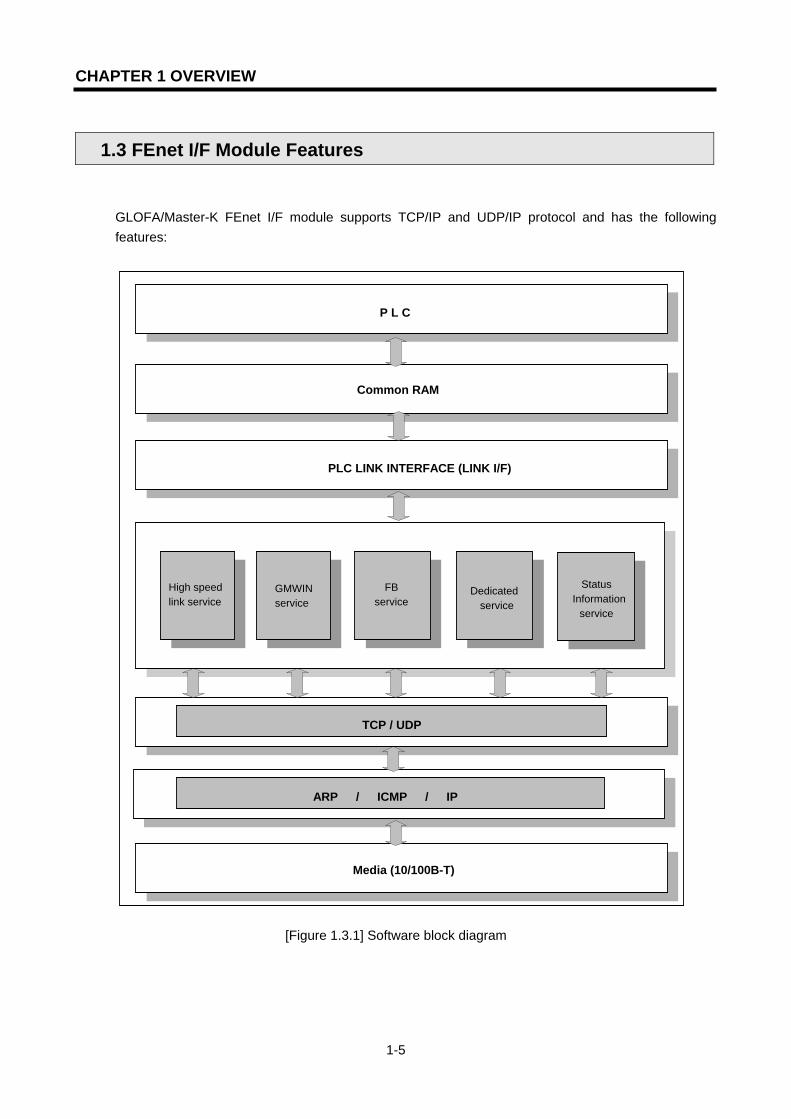
1.3 FEnet I/F Module Features
GLOFA/Master-K FEnet I/F module supports TCP/IP and UDP/IP protocol and has the following features:
[Figure 1.3.1] Software block diagram
Media (10/100B-T)
High speed link service
PLC LINK INTERFACE (LINK I/F)
P L C
Common RAM
TCP / UDP
ARP / ICMP / IP
Status Information
service
Dedicated service
FBservice
GMWIN service

CHAPTER 1 OVERVIEW
1-6
Fast Ethernet (FEnet I/F module):
Complies with the IEEE 802.3 standard (supports Ethernet specifications). Supports TCP, UDP, ARP, ICMP, IP protocols. Data access by public networks is available. Supports Dynamic Connection/Disconnection by using the function block. Supports High Speed Link for high speed data communication between LGIS modules. Available to communicate with 16 stations at the same time besides the High Speed Link .
(dedicated communication + function block communication). Loader service through Ethernet is available (dedicated TCP/IP PORT: 2002 assignment). Supports 10/100BASE-TX, 100BASE-FX, and 10BASE-5 media. Easy connection to other manufacturer’s systems by using function block and frame editor. Network status monitoring and information collection (LGIS communication module). TCP port 2004, UDP port 2005, High Speed Link port 2006, channel list port 2007 are
opened automatically when the Power is ON. (2002,2004,2005,2006,2007 ports are not allowed to be used when the function block is in service.)
Variable READ/WRITE service by using a function block is available (Dynamic Connection is used)
The installation of 2~8 Ethernet communication modules for one main base is available. Various system configurations by changing the basic parameter.

CHAPTER 1 OVERVIEW
1-7
1.4 FEnet I/F Module Configuration
1.4.1 Model Types
The following table describes the configuration of the GLOFA/MASTER-K FEnet I/F module.
Classification Model Description Remarks
G3L-EUTB 10/100BASE-TX Category 5
G3L-EUFB 100BASE-FX Fiber Optic GMR/1/2/3 &
K1000S G3L-EU5B 10BASE-5 AUI
G4L-EUTB 10/100BASE-TX Category 5
G4L-EUFB 10BASE-FX Fiber Optic GM4 & K300S
G4L-EU5B 10BASE-5 AUI
G6L-EUTB 10/100BASE-TX Category 5
GLOFA &
MASTER-K
GM6 & K200S G6L-EUFB 100BASE-FX Fiber Optic
Point
1) GM6/K200S does not support AUI (10BASE-5). 2) UTP twisted pair shield cable unit uses a 100Mbps switching hub and even if it is available to mix
with the existing 10Mbps (less than Category 3), the speed of the network should be limited to 10Mbps. Caution should be taken when installing the system.

CHAPTER 1 OVERVIEW
1-8
1.4.2 FEnet I/F module version compatibility table
The following table shows the compatible list of various CPU O/S versions in order to use the
FEnet I/F module. Before using, please refer to the table below for the system configuration.
1) In the case of using GLOFA
Classification Available communication module Version
GMR GMR-CPUA/B G3L-EUTB/EUFB/EU5B Higher than V2.2
GM1/2-CPUA GM1/2
GM2-CPUB G3L-EUTB/EUFB/EU5B Higher than V3.2
GM3 GM3-CPUA G3L-EUTB/EUFB/EU5B Higher than V2.7
GM4-CPUA Higher than V2.7
GM4-CPUB Higher than V2.7 GM4
GM4-CPUC
G4L-EUTB/EUFB/EU5B
Higher than V2.0
GM6 GM6-CPUA/B/C G6L-EUTB/EUFB Higher than V2.1
GMWIN All model Higher than V4.02
Frame editor All model Higher than V2.0
2) In the case of using MASTER-K
Classification Available communication module Version
K1000S K7P-30AS G3L-EUTB/EUFB/EU5B Higher than V3.2
K300S K4P-15AS G4L-EUTB/EUFB/EU5B Higher than V3.4
K200S K3P-07A/B/C G6L-EUTB/EUFB Higher than V2.4
KGLWIN All model Higher than V3.41
Frame editor All model Higher than V2.0
Point
1) If the corresponding version is not matched, normal communication it is not possible. Before using, make sure to verify the applicable CPU type and communication module version.

CHAPTER 1 OVERVIEW
1-9
1.4.3 Available installation number of FEnet I/F modules per CPU
The following table shows the max. installation number of FEnet I/F modules per CPU type.
Please refer to the number of communication modules before configuring the system.
1) In the case of using GLOFA
Classification Max. installation number
GMR GMR-CPUA/B 4EA
GM1/2-CPUA 4EA GM1/2
GM2-CPUB 8EA
GM3 GM3-CPUA 4EA
GM4-CPUA 2EA
GM4-CPUB 4EA GM4
GM4-CPUC 8EA POINT1)
GM6 GM6-CPUA/B/C 2EA
2) In the case of using MASTER-K
Classification Available communication module
K1000S K7P-30AS 4EA
K300S K4P-15AS 2EA
K200S K3P-07A/B/C 2EA
Point
1) For GM4-CPUC, it is available to install the communication module up to 8 extended steps. For more information, please refer to the GM3/4 user’s manual.

CHAPTER 1 OVERVIEW
1-10
1.5 Software for Product Use
The following describes the major programming tool and other manufacturer’s software in order to use the FEnet I/F module. For correct application of the program and communication, please refer to the following table.
1.5.1 Software Verification
1) In the case of the GLOFA /MASTER-K series
Classification Module Programming toolFrame
preparation Remarks
GLOFA GMWIN
MASTER-K
G3L-EUTB G3L-EUFB G3L-EU5B G4L-EUTB G4L-EUFB G4L-EU5B G6L-EUTB G6L-EUFB
KGLWIN
Frame editor (common)
For the available version, please refer to the Figure 1.4.2 FEnet I/F module
version compatibility table.
Point
1) The above programs are available to be downloaded from our website. If it is not possible to use the internet, visit our representative near you to get the corresponding CD-ROM data and install it. Internet website address: http://www.lgis.com
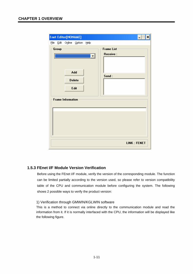
1.5.2 Frame Editor Frame editor is a software to define the protocol for the operation of the FEnet I/F module, and
edits the frame for data sending/receiving. It is needed to define the frame before preparing the
communication program. For more information, please refer to section 6.2 Frame Editor.
The following figure shows the initial screen of frame editor.
CHAPTER 1 OVERVIEW
1-11
1.5.3 FEnet I/F Module Version Verification Before using the FEnet I/F module, verify the version of the corresponding module. The function
can be limited partially according to the version used, so please refer to version compatibility
table of the CPU and communication module before configuring the system. The following
shows 2 possible ways to verify the product version:
1) Verification through GMWIN/KGLWIN software This is a method to connect via online directly to the communication module and read the information from it. If it is normally interfaced with the CPU, the information will be displayed like the following figure.

CHAPTER 1 OVERVIEW
1-12
First, connect to GMWIN and click the menu [Online]->[I/O Modules]->[I/O Info]. If you click the slot where the corresponding module is installed, the version information of the module will be displayed.
2) Verification using the product case label Each communication module has an external case with the module information attached. In the case when online verification is not possible, it can be used to verify the version after removing the module.
On the back side of the product, the label is attached and displays the product model name and version.
CHAPTER 1 OVERVIEW
1-13
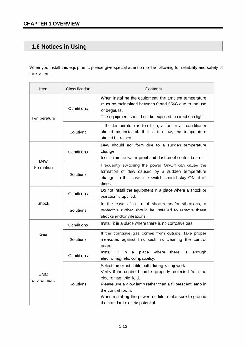
1.6 Notices in Using
When you install this equipment, please give special attention to the following for reliability and safety of the system.
Item Classification Contents
Conditions
When installing the equipment, the ambient temperature must be maintained between 0 and 55oC due to the use of degauss. The equipment should not be exposed to direct sun light. Temperature
Solutions If the temperature is too high, a fan or air conditioner should be installed. If it is too low, the temperature should be raised.
Conditions Dew should not form due to a sudden temperature change. Install it in the water-proof and dust-proof control board.
Dew Formation
Solutions
Frequently switching the power On/Off can cause the formation of dew caused by a sudden temperature change. In this case, the switch should stay ON at all times.
Conditions Do not install the equipment in a place where a shock or vibration is applied.
Shock
Solutions In the case of a lot of shocks and/or vibrations, a protective rubber should be installed to remove these shocks and/or vibrations.
Conditions Install it in a place where there is no corrosive gas.
Gas Solutions
If the corrosive gas comes from outside, take proper measures against this such as cleaning the control board.
Conditions Install it in a place where there is enough electromagnetic compatibility.
EMC environment
Solutions
Select the exact cable path during wiring work. Verify if the control board is properly protected from the electromagnetic field. Please use a glow lamp rather than a fluorescent lamp in the control room. When installing the power module, make sure to ground the standard electric potential.
CHAPTER 1 OVERVIEW
1-14
1.7 Terminology
Before using this product, this section describes the general terminology of the FEnet I/F module. For further information, please refer to the professional Ethernet-related books.
1) IEEE 802.3 IEEE 802.3 regulates a standard for CSMA/CD based Ethernet. More correctly speaking, this is a CSMA/CD (Carrier Sense Multiple Access with Collision Detection) Ethernet based LAN, designed by the IEEE 802.3 group and is divided into the detailed projects as follows: A) IEEE P802.3 - 10G Base T study Group B) IEEE P802.3ah - Ethernet in the First Mile Task Force C) IEEE P802.3ak - 10G Base-CX4 Task Force Both IEEE 802.3 and Ethernet are broadband networks using the CSMA/CD mode. A common feature between them is that both can be function using a Network Interface Card.
2) ARP (Address Resolution Protocol) A protocol used to obtain a MAC address by using the other’s IP address on the Ethernet LAN.
3) Bridge A device used to connect two networks together. The 2 networks may be the same or different, but they work as if they are one network. The Bridge is also used to divide a large network into two smaller ones in order to improve performance.
4) Client A user of a network service, a computer, or a program using another computer’s resources (mainly the part demanding service).
5) CSMA/CD (Carrier Sense Multiple Access with Collision Detection) An access method in which each client checks (Carrier Sense) the network for signals before sending a message. If the network is empty, it can send its data. At this time, every client has the same right to send its message (Multiple Access). If two or more signals from separae clients collide at exactly the same time, the client, which has detected it (Collision Detect) will retry to send its signal after a fixed time.
6) DNS (Domain Name System) A method used to convert the alphabetic domain name on the internet into the corresponding internet number (IP address).

CHAPTER 1 OVERVIEW
1-15
7) Dot Address An IP address expressed as ‘100.100.100.100’. Each number is expressed using the decimal system, and each number possesses 1 byte out of a total of 4 bytes.
8) E-mail Address An address of a user possessing a login account for a specific machine connected to the internet. It is generally given in the format of ‘user’s ID@domain name (machine name)’. For example, it is like ‘ [email protected]. The @ symbol is pronounced ’at’ and will be shown when pressing ‘shift+2’ on the key board. The name after @ is the domain name of the specific company, school, institute, etc. connected to the internet. The name before @ is the ID of the user who is registered to the machine. The last letter group of the domain name of the top level. The following abbreviations are the most frequently used examples in the U.S.A, and around a the world. .com: mostly for companies / .edu: mostly for educational institutes like universities (education). In Korea, ‘.ac (academy)’ is mainly used for educational institutes. / .gov: mostly for government-related groups. For example, NASA is nasa.gov (government) / .mil: for military-related site. For example, U.S. Air Force is af.mil (military) / .org: for non-profit organization / .au: for Australia / .uk: for United Kingdom / .ca: for Canada / .kr: for Korea / .jp: for Japan / .fr: for France / .tw: for Taiwan, etc.
9) Ethernet The representative LAN access method (IEEE 802.3) developed in a joint venture by Xerox, Intel, DEC in the U.S.A. This network connection system has a transfer capability of 10Mbps, and uses packets of 1.5kB. Since Ethernet can connect various types of computers to a network, its name is now a synonym for LAN. Its product range is not limited to a few users anymore, but is so widespread that every enterprise can get various Ethernet products on the market.
10) FTP (File Transfer Protocol) One of the application programs offered by TCP/IP protocol. It is used to transfer files between computers. If a user possesses a login account to his computer, the computer can promptly log in and copy any file wherever it is located in the world.
11) Gateway This software/hardware converts two different types of protocols so that they perform without any problems. This plays a role as an entry/exit point to the network where information is exchanged between different systems.
12) Header A part of a packet containing the address of the localstation, the destination stations, and the error check section.

CHAPTER 1 OVERVIEW
1-16
13) HTML Hypertext Markup Language, standard language of the world wide web. A protocol supporting the hypermedia method.
14) HTTP Hypertext Transfer Protocol, standard protocol of the world wide web. A protocol supporting the hypermedia method.
15) ICMP (Internet Control Message Protocol) It creates an error message and test packet to manage the internet by the IP address expansion protocol.
16) IP (Internet Protocol) A protocol of network layers for the internet.
17) IP Address (Internet Protocol Address) The internet address, written as numbers, on the internet of each computer. It is a binary number with a size of 32 bits (4 bytes) to differentiate each machine on the internet. IP addresses are made up of two addresses, the network address used to differentiate the network and the host address used to differentiate the host. The network address and the host address are divided into 3 classes, A/B/C, according to how many bits are assigned to them. The IP address can not be voluntarily selected because it is the only one all over the world. It is assigned by local NIC (Network Information Center) when subscribing to the internet. In Korea, it is a job of KRNIC to do so. For example: 165.244.149.190
18) ISO (International Organization for Standardization) An organization under the umbrella of the U.N. that sets and controlls international standards.
19) LAN (Local Area Network) It is also called a local network or an info-communication network within an area. This network allows users within a confined geographical area to exchange and share data with each other using their personal computers connected to a communications line.
20) MAC (Medium Access Control) A method in a broadcast network in which the owner of the data determines which device has access to the network within the time allowed
21) Node Each personal computer connected to a network is called node.

CHAPTER 1 OVERVIEW
1-17
22) Packet A block of data as a basic unit used to transfer data through a network. A packet’s size ranges from a dozen to hundreds of bytes, and attaches a header at the front of it. The header contains the information of the packet’s destination and other required information.
23) PORT number A number used to distinguish a application on a TCP/UDP. Example) 21/tcp: Telnet
24) PPP (Point-to-Point Protocol) Telephone communication protocol that allows packet transmissions when accessing the internet. It is namely the most popular protocol of the internet. PPP allows a computer to be connected to TCP/IP by using normal a telephone circuit and modem. It is similar to SLIP, but it demonstrates a much greater performance than SLIP because it contains modern communication protocol elements such as error detection, data compression, etc.
25) Protocol Standards on the method of data transmission between the computers connected to the network. It can also define the low and high level message exchange standards. In other words, interfaces between machines are described in detail by the low level, for example which bit/byte must go through the line, or defines the high level message exchange standards as it transfers the file through the internet.
26) Router A device used when transferring data packets between networks. It transfers data packets to the final destination. If the network is busy, it waits for a moment, and then retries. It judges which LAN it should connect to where at multiple LAN branch points. In other words, it is a special computer/software that manages more than 2 network connections.
27) Server A computer software application that carries out some task on behalf of users. This is usually divided into file serving, allowing users to store and access files on a common computer; and application serving, where the software runs a computer program to carry out some task for the users.
28) TCP (Transmission Control Protocol) A transport layer protocol for the internet - Sends and receives data by using a connection - Multiplexing - Reliable sending
- Supports urgent data sending

CHAPTER 1 OVERVIEW
1-18
29) TCP/IP (Transmission Control Protocol/Internet Protocol ) Transmission protocol for the communication between different types of computers. It allows them to possibly communicate between general PC and a medium-sized host, between IBM PC and MAC PC, and between medium-sized and large-sized computers of other companies. It is used as a generic name to transport information between computer networks. These include FTP, Telnet, SMTP. TCP segments data into packets, and is sent by IP. The packet sent by IP is bundled by TCP again.
30) Telnet It allows a user to perform a remote login from a host to another host through the internet. To log in on to a remote host with TELNET, the user must have an account on the host. However, it is possible to log in freely on the hosts that offer several public services such as the white pages directory, even if the user does not have his own personal account.
31) Token Ring A local area network (LAN) containing a physical ring structure, and using Token to access a network. It is also one of the node access methods in network. When a node sending data gains control by getting a Token, it can send its message packet. IEEE 802.5, ProNet-1080 and FDDI are good examples of it. The term ‘ring’ is often used as the substitute for IEEE 802.5.
32) UDP (User Datagram Protocol) A transport layer protocol for the internet - Makes high-speed communication possible by sending and receiving data without a connection - Multiplexing - Low reliability of data transport compared to TCP. In other words, if the data has not reached
the partner station, it does not try to send the data again.
TokenRing
Token passing
Dual Token passing

CHAPTER 1 OVERVIEW
1-19
33) Auto-Negotiation Fast Ethernet is the process that the Ethernet device changes the information for the performance such as active speed, duplex mode, and etc. 1. Find out the reason that the connection is denied 2. Determine the performance of the network equipment 3. Change the access speed
34) FDDI (Fiber Distributed Data Interface) This provides a speed of 100Mbps based on the fiber optic cable. It is a Shared Media Network that enables the interactive token passing by a dual ring mode. Max. distance of the total network is 200Km. The max. distance between nodes is 2Km. The max. node number is 500(1000). Generally, this is used as a Backbone Network.
CHAPTER 2 PRODUCT SPECIFICATIONS
2-1
CHAPTER 2 PRODUCT SPECIFICATIONS
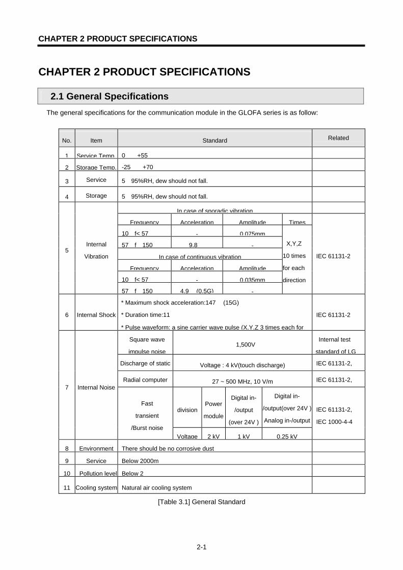
2.1 General Specifications The general specifications for the communication module in the GLOFA series is as follow:
No. Item Standard Related
1 Service Temp. 0∼+55
2 Storage Temp. -25∼+70
3 Service 5∼95%RH, dew should not fall.
4 Storage 5∼95%RH, dew should not fall.
In case of sporadic vibration
Frequency Acceleration Amplitude Times
10≤f< 57 - 0.075mm
57≤f≤150 9.8 -
In case of continuous vibration
Frequency Acceleration Amplitude
10≤f< 57 - 0.035mm
5 Internal
Vibration
57≤f≤150 4.9 (0.5G) -
X,Y,Z
10 times
for each
direction
IEC 61131-2
6 Internal Shock
* Maximum shock acceleration:147 (15G)
* Duration time:11
* Pulse waveform: a sine carrier wave pulse (X,Y,Z 3 times each for
IEC 61131-2
Square wave
impulse noise±1,500V
Internal test
standard of LG
Discharge of static Voltage : 4 kV(touch discharge) IEC 61131-2,
Radial computer 27 ~ 500 MHz, 10 V/m IEC 61131-2,
divisionPower
module
Digital in-
/output
(over 24V )
Digital in-
/output(over 24V )
Analog in-/output
7 Internal Noise
Fast
transient
/Burst noise Voltage 2 kV 1 kV 0.25 kV
IEC 61131-2,
IEC 1000-4-4
8 Environment There should be no corrosive dust
9 Service Below 2000m
10 Pollution level Below 2
11 Cooling system Natural air cooling system
[Table 3.1] General Standard

CHAPTER 2 PRODUCT SPECIFICATIONS
2-2
Point
1) IEC (International Electro technical Commission) International non-governmental organization promoting international cooperation on the
standardization of electric and electronic techniques. It also sets international standards, evaluates, and manages their suitability. 2) Pollution Level An index showing the extent of pollution of the service environment for a device where the environment is crucial for its performance. Pollution level 2 means the status in which only non-conductible pollution occurs. However, conduction pollution due to dewfall also falls under pollution level 2.

CHAPTER 2 PRODUCT SPECIFICATIONS
2-3
2.2 Performance Specifications This section describes the specification of system configuration according to the FEnet I/F module media. When configuring the system, please refer to the table below.
Specifications Items
10BASE-5 100BASE-FX 10/100BASE-TX
Transmission speed 10Mbps 100Mbps 10/100Mbps
Transmission mode Base band
Inter-node max. extension distance
2.5km 2km -
Max. segment length 500m - 100m
(node-hub)
Max. node number 100EA
/segment 30EA
/segment Hub 4 steps Accessible
Node interval Constant
magnification of 2.5m
Constant magnification of
0.5m -
Max. protocol size 1,500 Byte
Communication area access mode
CSMA/CD
Tran
smis
sion
sp
ecifi
catio
ns
Frame error check method
CRC 16 = X15 + X14 + X13+ .... + X2 + X + 1
Consumed current Less than 600mA
Basi
c sp
ecifi
catio
ns
Weight(g) G3L-EUTB/EUFB/EU5B:380/377/385 G4L-EUTB/EUFB/EU5B:212/218/225 G6L-EUTB/EUFB:121/118
CHAPTER 2 PRODUCT SPECIFICATIONS
2-4
2.3 Structure and Characteristics
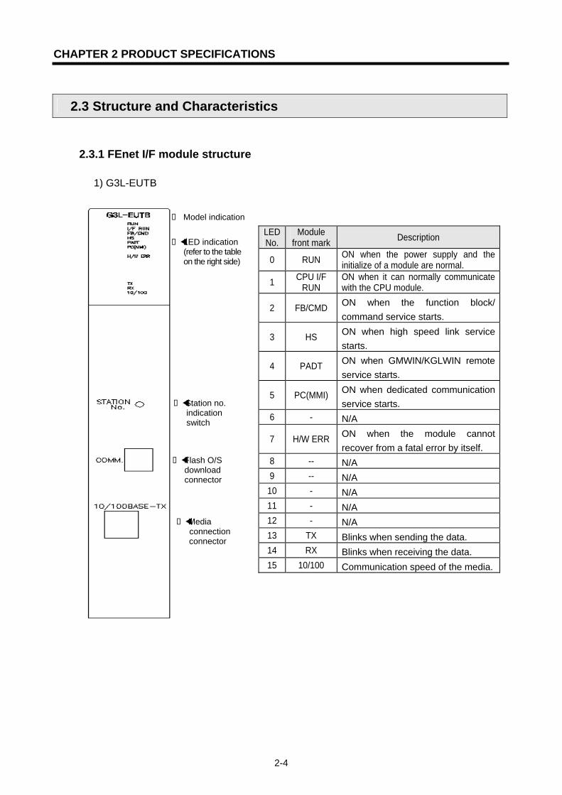
2.3.1 FEnet I/F module structure
1) G3L-EUTB
LED No.
Module front mark Description
0 RUN ON when the power supply and the initialize of a module are normal.
1 CPU I/F RUN
ON when it can normally communicate with the CPU module.
2 FB/CMD ON when the function block/ command service starts.
3 HS ON when high speed link service starts.
4 PADT ON when GMWIN/KGLWIN remote service starts.
5 PC(MMI) ON when dedicated communication service starts.
6 - N/A
7 H/W ERR ON when the module cannot recover from a fatal error by itself.
8 -- N/A 9 -- N/A
10 - N/A 11 - N/A 12 - N/A 13 TX Blinks when sending the data. 14 RX Blinks when receiving the data. 15 10/100 Communication speed of the media.
Model indication
LED indication (refer to the table on the right side)
Station no. indication
switch
Flash O/S download connector
Media connection connector

CHAPTER 2 PRODUCT SPECIFICATIONS
2-5
2) G3L-EUFB
LED No.
Module front mark Description
0 RUN ON when the power supply and the initialize of a module are normal.
1 I/F RUN ON when it can normally communicate with the CPU module.
2 FB/CMD ON when the function block/ command service starts.
3 HS ON when high speed link service starts.
4 PADT ON when GMWIN/KGLWIN remote service starts.
5 PC(MMI) ON when dedicated communication service starts.
6 - N/A
7 H/W ERR ON when the module cannot recover from a fatal error by itself.
8 -- N/A 9 -- N/A
10 - N/A 11 - N/A 12 - N/A 13 TX Blinks when sending the data. 14 RX Blinks when receiving the data.
15 10/100 Communication speed of the media.
Model indication
LED indication (refer to the table
on the right side)
Station no. indication switch
Flash O/S download connector
Media connection connector

CHAPTER 2 PRODUCT SPECIFICATIONS
2-6
3) G3L-EU5B
LED No.
Module front mark Description
0 RUN ON when the power supply and the initialize of a module are normal.
1 I/F RUN ON when it can normally communicate with the CPU module.
2 FB/CMD ON when the function block/ command service starts.
3 HS ON when high speed link service starts.
4 PADT ON when GMWIN/KGLWIN remote service starts.
5 PC(MMI) ON when dedicated communication service starts.
6 - N/A
7 H/W ERR ON when the module cannot recover from a fatal error by itself.
8 -- N/A 9 -- N/A
10 - N/A 11 - N/A 12 - N/A 13 TX Blinks when sending the data. 14 RX Blinks when receiving the data. 15 10/100 Communication speed of the media.
Model indication
LED indication (refer to the tableon the right side.)
Station no. indication switch
Flash O/S download connector
Media connection connector
External power supply terminal (12VDC)
CHAPTER 2 PRODUCT SPECIFICATIONS
2-7
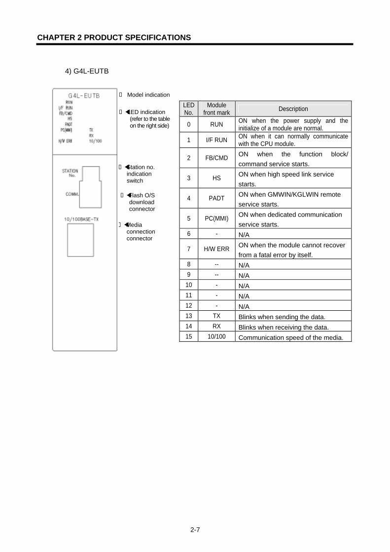
4) G4L-EUTB
LED No.
Module front mark Description
0 RUN ON when the power supply and the initialize of a module are normal.
1 I/F RUN ON when it can normally communicate with the CPU module.
2 FB/CMD ON when the function block/ command service starts.
3 HS ON when high speed link service starts.
4 PADT ON when GMWIN/KGLWIN remote service starts.
5 PC(MMI) ON when dedicated communication service starts.
6 - N/A
7 H/W ERR ON when the module cannot recover from a fatal error by itself.
8 -- N/A 9 -- N/A
10 - N/A 11 - N/A 12 - N/A 13 TX Blinks when sending the data. 14 RX Blinks when receiving the data. 15 10/100 Communication speed of the media.
Model indication
LED indication (refer to the tableon the right side)
Station no. indication switch
Flash O/S download connector
Media connection connector
CHAPTER 2 PRODUCT SPECIFICATIONS
2-8
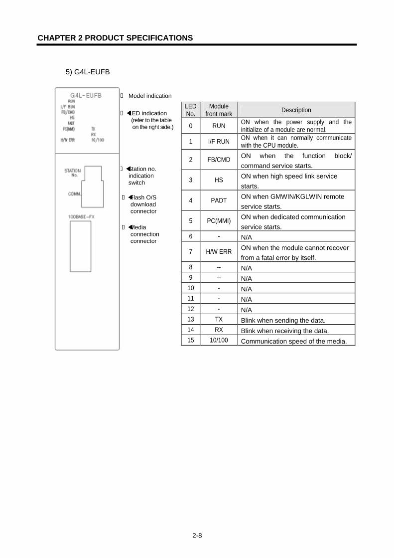
5) G4L-EUFB
LED No.
Module front mark Description
0 RUN ON when the power supply and the initialize of a module are normal.
1 I/F RUN ON when it can normally communicate with the CPU module.
2 FB/CMD ON when the function block/ command service starts.
3 HS ON when high speed link service starts.
4 PADT ON when GMWIN/KGLWIN remote service starts.
5 PC(MMI) ON when dedicated communication service starts.
6 - N/A
7 H/W ERR ON when the module cannot recover from a fatal error by itself.
8 -- N/A 9 -- N/A
10 - N/A 11 - N/A 12 - N/A 13 TX Blink when sending the data. 14 RX Blink when receiving the data. 15 10/100 Communication speed of the media.
Model indication
LED indication (refer to the tableon the right side.)
Station no. indication switch
Flash O/S download connector
Media connection connector
CHAPTER 2 PRODUCT SPECIFICATIONS
2-9
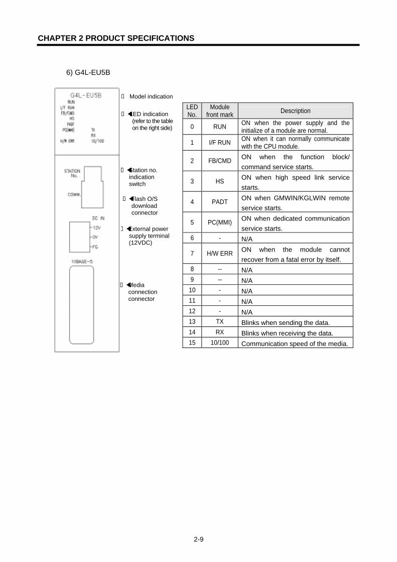
6) G4L-EU5B
LED No.
Module front mark Description
0 RUN ON when the power supply and the initialize of a module are normal.
1 I/F RUN ON when it can normally communicate with the CPU module.
2 FB/CMD ON when the function block/ command service starts.
3 HS ON when high speed link service starts.
4 PADT ON when GMWIN/KGLWIN remote service starts.
5 PC(MMI) ON when dedicated communication service starts.
6 - N/A
7 H/W ERR ON when the module cannot recover from a fatal error by itself.
8 -- N/A 9 -- N/A
10 - N/A 11 - N/A 12 - N/A 13 TX Blinks when sending the data. 14 RX Blinks when receiving the data. 15 10/100 Communication speed of the media.
Model indication
LED indication (refer to the tableon the right side)
Station no. indication switch
Flash O/S download connector
External power supply terminal(12VDC)
Media connection connector

CHAPTER 2 PRODUCT SPECIFICATIONS
2-10
7) G6L-EUTB
LED No.
Module front mark Description
0 RUN ON when the power supply and the initialize of a module are normal.
1 I/F RUN ON when it can normally communicate with the CPU module.
2 FB/CMD ON when the function block/ command service starts.
3 HS ON when high speed link service starts.
4 PADT(PC) ON when GMWIN/KGLWIN remote service or MMI service starts.
5 TX Blinks when sending the data. 6 RX Blinks when receiving the data. 7 10/100 Communication speed of the media.
Model indication
LED indication (refer to the tableon the right side)
Station no. indication switch
Flash O/S download connector
Media connection connector

CHAPTER 2 PRODUCT SPECIFICATIONS
2-11
8) G6L-EUFB
LED No.
Module front mark Description
0 RUN ON when the power supply and the initialize of a module are normal.
1 I/F RUN On when it can normally communicate with the CPU module.
2 FB/CMD ON when the function block/ command service starts.
3 HS ON when high speed link service starts.
4 PADT(PC) ON when GMWIN/KGLWIN remote service or MMI service starts.
5 TX Blinks when sending the data. 6 RX Blinks when receiving the data. 7 10/100 Communication speed of the media.
Model indication
LED indication (refer to the tableon the right side)
Station no. indication switch
Flash O/S download connector
Media connection connector
CHAPTER 2 PRODUCT SPECIFICATIONS
2-12
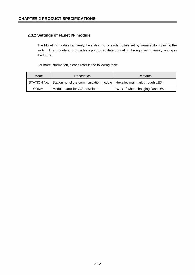
2.3.2 Settings of FEnet I/F module
The FEnet I/F module can verify the station no. of each module set by frame editor by using the switch. This module also provides a port to facilitate upgrading through flash memory writing in the future. For more information, please refer to the following table.
Mode Description Remarks
STATION No. Station no. of the communication module Hexadecimal mark through LED
COMM. Modular Jack for O/S download BOOT / when changing flash O/S

CHAPTER 2 PRODUCT SPECIFICATIONS
2-13
2.4 Cable Specifications
2.4.1 Ethernet/IEEE 802.3 related cable specifications
Classification 10Base-5 coaxial cable AUI cable Characteristic
impedance 50Ω±2Ω 78Ω±5Ω
Attenuation Less than 8.5dB at 10MHz, 500m,
Less than 3dB at 10MHz, 50m
Transmission speed C=the velocity of light (3.00 ⅹ 108 km/s)
More than 0.77C More than 0.65C
Phase Jitter less than ±7ns at 500m terminal
less than±1ns at 50m terminal
Others
PVC jacket outside diameter 10.287±0.178mm
FEP jacket outside diameter 9.525±0.254mm
Conducting wire resistance for power,Less than 40mΩ/m
2.4.2 UTP cable
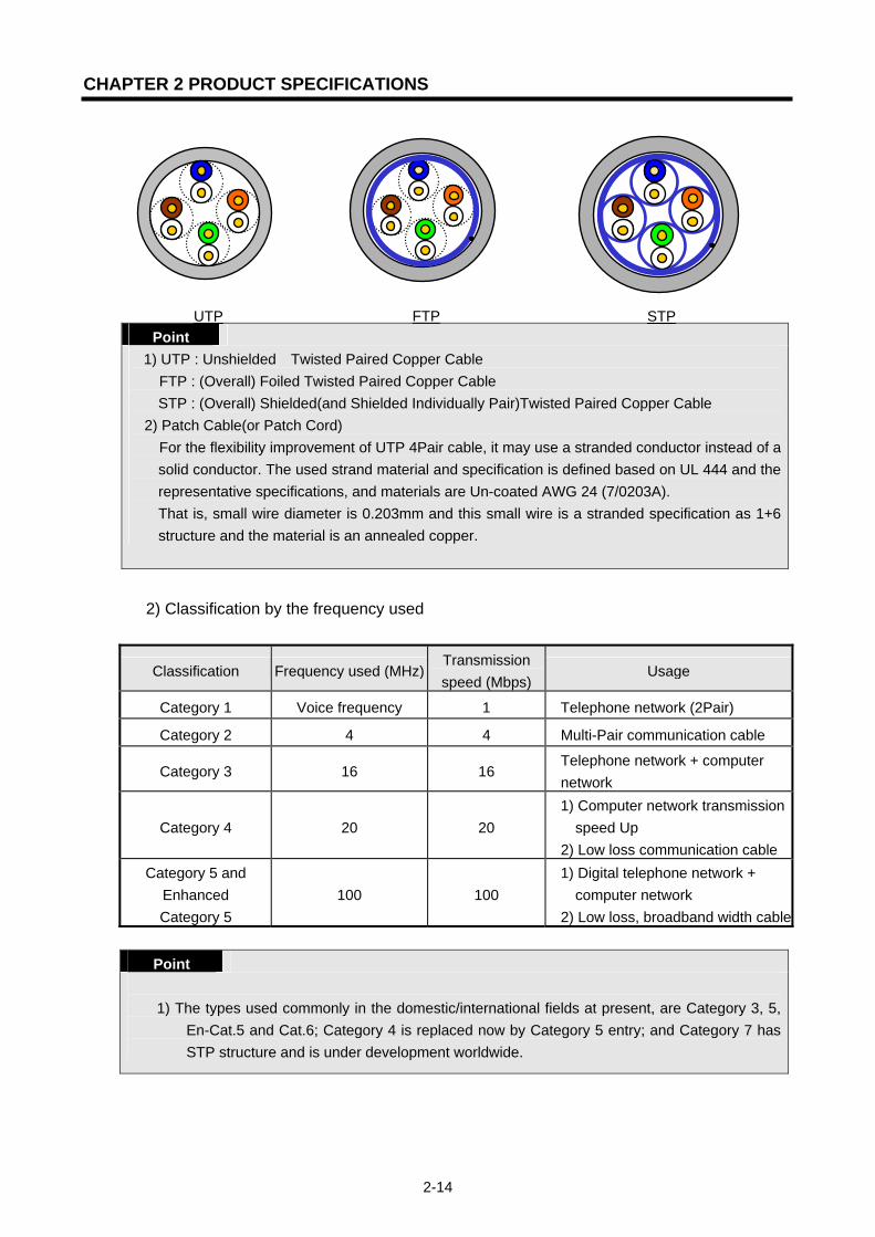
UTP cable is classified by 3 types based on the following criteria : ① Shield Y/N: 3 types (UTP, FTP, STP)
② use frequency band : 7 types (Cat.1~7) ③ non-flammable class : 4 types (CMX, CM, CMR, CMP)
1) Cable types according to Shield Yes/No Classification Details Uses
UTP(or U.UTP) Non-shield high speed signal cable Max. 200MHz Voice+Information(Data)+low grade image signal
FTP(or S.UTP)
Only cable core shielded cable by singleshield *Shield material: AL/Plastic complex foil or Copper Braid
Max. 100MHz Electronic obstacle(EMI) or electricstability considered Voice+Information(Data)+low grade image (Video) signal
STP(or S.STP)
Pair or individually shielded or cable coreshielded cable by duplex shield * Pair shield material
: AL/Plastic complex foil * Core shield material
: AL/Plastic complex foil or Copper Braid
Max. 500MHz Voice+information(Data)+ image(Video) signal 75Ω coaxial cable alternative
CHAPTER 2 PRODUCT SPECIFICATIONS
2-14
Point 1) UTP : Unshielded Twisted Paired Copper Cable
FTP : (Overall) Foiled Twisted Paired Copper Cable STP : (Overall) Shielded(and Shielded Individually Pair)Twisted Paired Copper Cable
2) Patch Cable(or Patch Cord) For the flexibility improvement of UTP 4Pair cable, it may use a stranded conductor instead of a solid conductor. The used strand material and specification is defined based on UL 444 and the representative specifications, and materials are Un-coated AWG 24 (7/0203A). That is, small wire diameter is 0.203mm and this small wire is a stranded specification as 1+6 structure and the material is an annealed copper.
2) Classification by the frequency used
Classification Frequency used (MHz)Transmission speed (Mbps)
Usage
Category 1 Voice frequency 1 Telephone network (2Pair)
Category 2 4 4 Multi-Pair communication cable
Category 3 16 16 Telephone network + computer network
Category 4 20 20 1) Computer network transmission
speed Up 2) Low loss communication cable
Category 5 and Enhanced Category 5
100 100 1) Digital telephone network +
computer network 2) Low loss, broadband width cable
Point
1) The types used commonly in the domestic/international fields at present, are Category 3, 5,
En-Cat.5 and Cat.6; Category 4 is replaced now by Category 5 entry; and Category 7 has STP structure and is under development worldwide.
UTP STP FTP
CHAPTER 2 PRODUCT SPECIFICATIONS
2-15
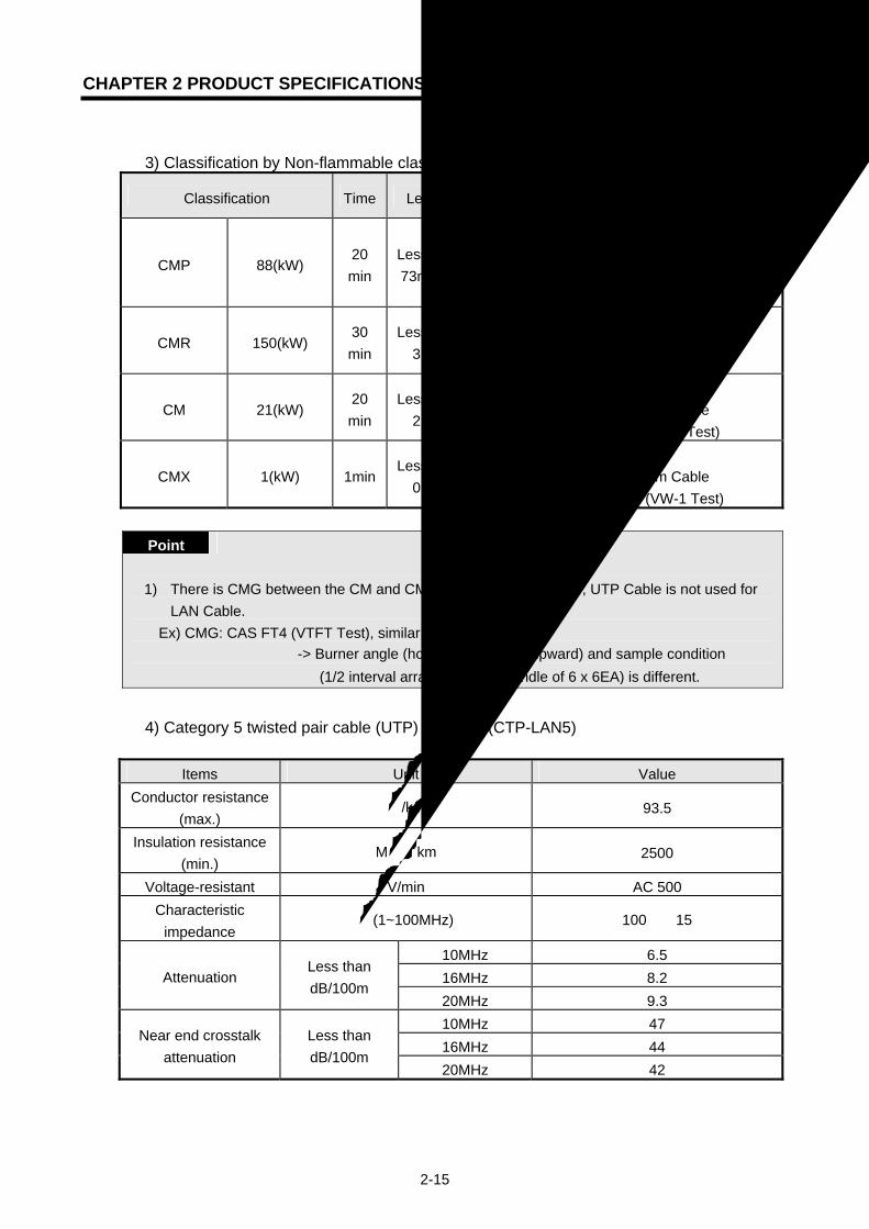
3) Classification by Non-flammable class (based on UL certificate)
Classification Time Length Smoke retard
Remarks
CMP 88(kW) 20 min
Less than 73m/min
Restricted
• Ceiling installation without duct • Plenum Cable • UL 910 (Plenum Test)
CMR 150(kW) 30 min
Less than 3.6m
Unrestricted• Vertical installation • Non-Plenum Cable • UL 1666(Riser Test)
CM 21(kW) 20 min
Less than 2.4m
Unrestricted• General type • Non-Plenum Cable • UL 1581(VTFT Test)
CMX 1(kW) 1minLess than
0.5m Unrestricted
• limited use • Non-Plenum Cable • UL 1581 (VW-1 Test)
Point
1) There is CMG between the CM and CMR classes, but generally, UTP Cable is not used for
LAN Cable. Ex) CMG: CAS FT4 (VTFT Test), similar to CM of UL 1581
-> Burner angle (horizontal -> 45° upward) and sample condition (1/2 interval arrangement -> bundle of 6 x 6EA) is different.
4) Category 5 twisted pair cable (UTP) example (CTP-LAN5)
Items Unit Value Conductor resistance
(max.) Ω/km 93.5
Insulation resistance (min.)
MΩ·km 2500
Voltage-resistant V/min AC 500 Characteristic
impedance Ω(1~100MHz) 100 ± 15
10MHz 6.5 16MHz 8.2 Attenuation
Less than dB/100m
20MHz 9.3 10MHz 47 16MHz 44
Near end crosstalk attenuation
Less than dB/100m
20MHz 42
CHAPTER 2 PRODUCT SPECIFICATIONS
2-16
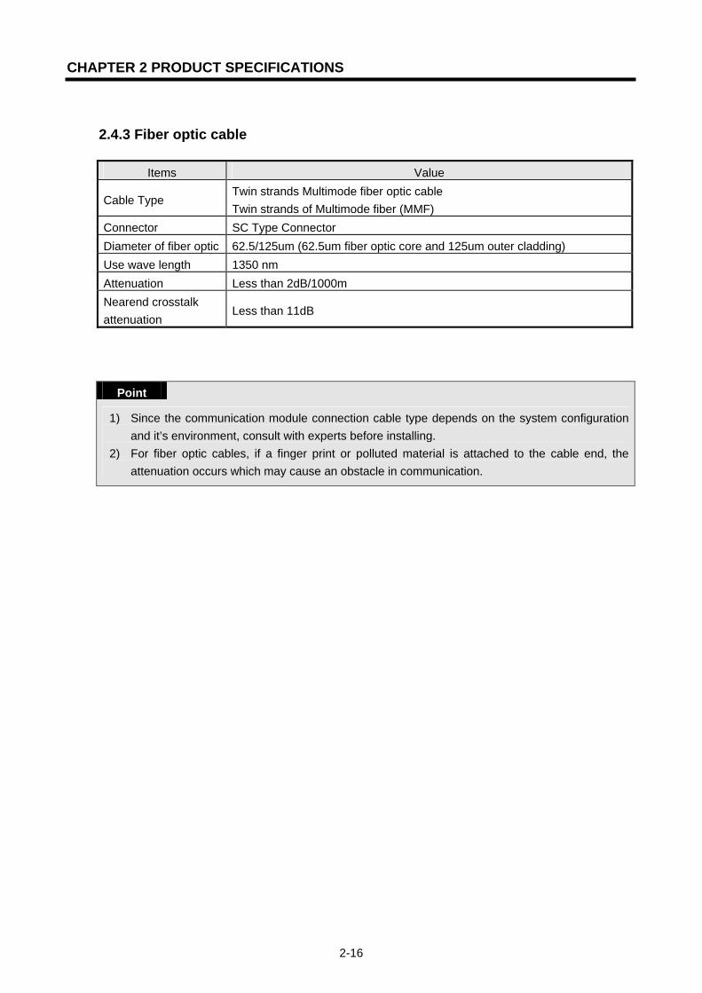
2.4.3 Fiber optic cable
Items Value
Cable Type Twin strands Multimode fiber optic cable Twin strands of Multimode fiber (MMF)
Connector SC Type Connector Diameter of fiber optic 62.5/125um (62.5um fiber optic core and 125um outer cladding) Use wave length 1350 nm Attenuation Less than 2dB/1000m Nearend crosstalk attenuation
Less than 11dB
Point
1) Since the communication module connection cable type depends on the system configuration and it’s environment, consult with experts before installing.
2) For fiber optic cables, if a finger print or polluted material is attached to the cable end, the attenuation occurs which may cause an obstacle in communication.

CHAPTER 3 INSTALLATION AND STARTUP
3-1
CHAPTER 3 INSTALLATION AND STARTUP
3.1 Notices in Handling
3.1.1 Notices in handling
For the system configuration of the FEnet I/F module, it is required to verify the following items before installing.
1) Check basic factors required for the system configuration and select the correct
communication module for the unit. 2) Select the cable to be used for the communication module. (only one from
10/100BASE-TX, 100BASE-FX and 10BASE-5, is available.)
3) Check for any foreign substance on the base connector where the module is to be mounted
prior to installation of the communication module. Verify if any connector pins of the module
are damaged.
4) All communication modules cannot be mounted on the extended base. Some may be securely
mounted to the main base at the slot positioned nearest the CPU.
5) While the module installation, the unconnected communication cables might have some
interface errors.
6) The cables to be used for this communication module are 10/100BASE-TX, 100BASE-FX,
10BASE-5. Only one should be used for the installation.
7) Select the ensured product for the switch hub and cable necessary for FEnet I/F module
communication.

CHAPTER 3 INSTALLATION AND STARTUP
3-2
3.1.2 Materials required for installation
Required materials 10/100BASE-TX 10BASE-5 Coaxial cable (impedance 50Ω)
N/A AUI exists.
AUI cable N/A Yellow Cable both ends N type connector(female)
Twisted pair cable (impedance 100Ω)
4 pairs twisted pair cable (8 pole plug of both ends)
N/A
Transceiver In case of using AUI, MAU of 10BASE-5 needed.
Using
End resistance (50Ω) N/A N type connector (male) T type connector N/A N/A Hub Using N/A
Fiber optic cable 62.5/125μm MMF(Multi Mode Fiber) Cable SC Type connector
Hub/Switch Optic Switch needed
CHAPTER 3 INSTALLATION AND STARTUP
3-3
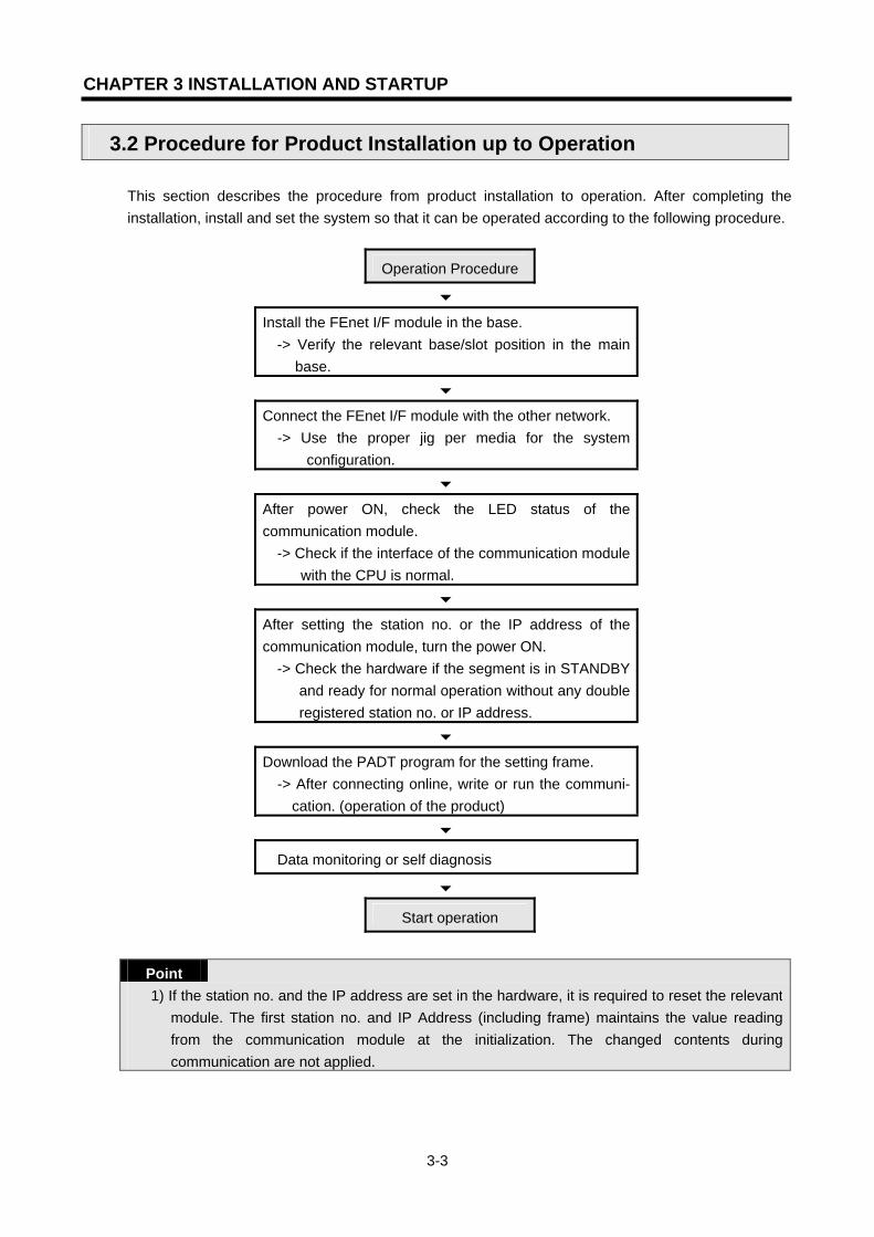
3.2 Procedure for Product Installation up to Operation
This section describes the procedure from product installation to operation. After completing the installation, install and set the system so that it can be operated according to the following procedure.
Operation Procedure
6 Install the FEnet I/F module in the base.
-> Verify the relevant base/slot position in the main base.
6 Connect the FEnet I/F module with the other network.
-> Use the proper jig per media for the system configuration.
6 After power ON, check the LED status of the communication module.
-> Check if the interface of the communication module with the CPU is normal.
6 After setting the station no. or the IP address of the communication module, turn the power ON.
-> Check the hardware if the segment is in STANDBY and ready for normal operation without any double registered station no. or IP address.
6 Download the PADT program for the setting frame.
-> After connecting online, write or run the communi- cation. (operation of the product)
6 Data monitoring or self diagnosis
6 Start operation
Point
1) If the station no. and the IP address are set in the hardware, it is required to reset the relevant module. The first station no. and IP Address (including frame) maintains the value reading from the communication module at the initialization. The changed contents during communication are not applied.
CHAPTER 3 INSTALLATION AND STARTUP
3-4
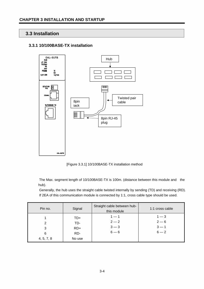
3.3 Installation 3.3.1 10/100BASE-TX installation
[Figure 3.3.1] 10/100BASE-TX installation method
The Max. segment length of 10/100BASE-TX is 100m. (distance between this module and the hub). Generally, the hub uses the straight cable twisted internally by sending (TD) and receiving (RD). If 2EA of this communication module is connected by 1:1, cross cable type should be used.
Pin no. Signal Straight cable between hub-
this module 1:1 cross cable
1 2 3 6
4, 5, 7, 8
TD+ TD- RD+ RD-
No use
1 — 1 2 — 2 3 — 3 6 — 6
1 — 3 2 — 6 3 — 1 6 — 2
8pin RJ-45plug
8pin jack
Twisted pair cable
Hub

CHAPTER 3 INSTALLATION AND STARTUP
3-5
Point
1) 10/100BASE-TX cable is subject to the external noise of the structure, Therefore, it is required to assemble the cable by twisting the cord of no.1 & no.2 pin (TD+, TD-) and the cord of no.3 & no.6 pin (RD+, RD-) to decrease the noise.
2) For hub power, use noise-free power by separating from the PLC power. 3) For cable terminal treatment or manufacturing, consult with the relevant experts.
1) UTP installation method
(1) For the reliable transmission of 100Mbps signals by using UTP cable, Patch cord, Line
cord, Patch panel, DVO (Data Voice Outlet) etc. must satisfy with Category 5 Specifications.(EIA/TIA-568A).
(2) The length of the Patch cord in the Cross-connect system should be within 7m. If it exceeds 7m, it is required to deduct as much of the relevant length from the 90m allowed in the horizontal distribution system.
(3) The line cord length of the workstation should be within 3m. If it exceeds 3m, it is required to deduct as much of the relevant length from the 90m allowed in the horizontal distribution system.
(4) When connecting the cable to the Patch panel and the DVO, the pitch loosening of the UTB cable should not exceed the following dimensions:
* Max. pitch of twisted wire loosening : Category 5 : 13mm Category 3 : 26mm (5) Jumper wire should be used in the IDC cross-connect system and in this case, the pitch
of twisted wire loosening should not exceed the above criteria. If the cable is bent seriously, it may cause damage to the cable or decrease the pair-to-pair clearance, cautions should be used. * Max. curvature radius : 4Pair cable : 4times the outside diameter.
more than 25Pair cable: 10times the outside diameter. (6) The Max. tension force during wiring should not exceed 110N (11.3Kgf) based on 4Pair. (7) When peeling the jacket, it is required to peel as long as the length desired to connect the
cable. Be careful not to damage the insulation. (8) Jumper Wire and Patch cord should be connected a little loose. If connected tightly, the
Category 5 characteristic may be removed. In the case of using Tie-wrap, do not apply stress to the cable.
(9) When installing UTP cable, keep the proper distance between the EMI source and the UTP cable.
CHAPTER 3 INSTALLATION AND STARTUP
3-6
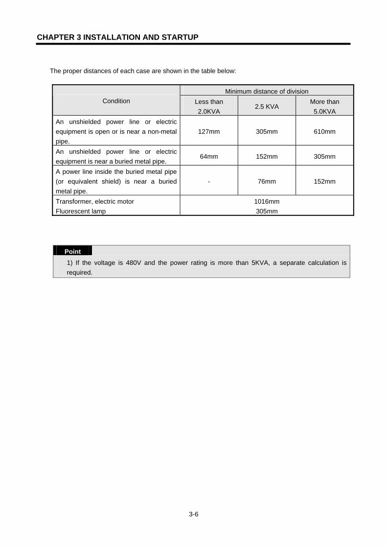
The proper distances of each case are shown in the table below:
Minimum distance of division Condition Less than
2.0KVA 2.5 KVA
More than 5.0KVA
An unshielded power line or electric equipment is open or is near a non-metal pipe.
127mm 305mm 610mm
An unshielded power line or electric equipment is near a buried metal pipe.
64mm 152mm 305mm
A power line inside the buried metal pipe (or equivalent shield) is near a buried metal pipe.
- 76mm 152mm
Transformer, electric motor Fluorescent lamp
1016mm 305mm
Point
1) If the voltage is 480V and the power rating is more than 5KVA, a separate calculation is required.
CHAPTER 3 INSTALLATION AND STARTUP
3-7
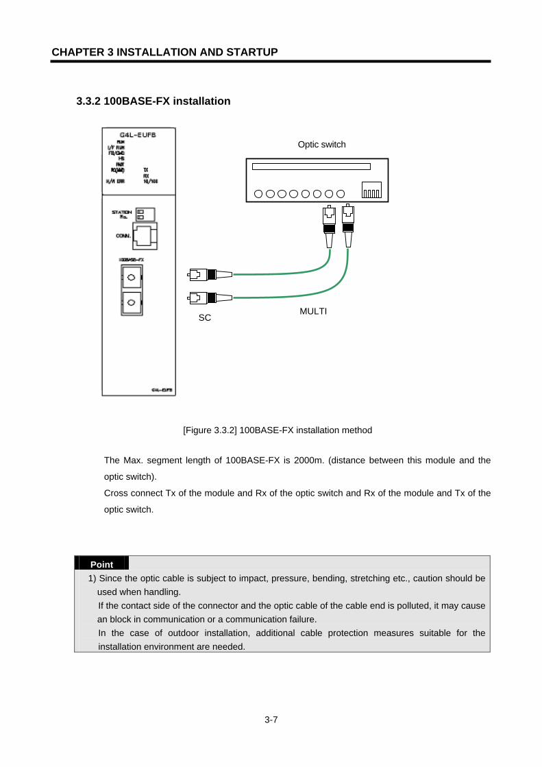
3.3.2 100BASE-FX installation
[Figure 3.3.2] 100BASE-FX installation method
The Max. segment length of 100BASE-FX is 2000m. (distance between this module and the
optic switch).
Cross connect Tx of the module and Rx of the optic switch and Rx of the module and Tx of the
optic switch.
Point
1) Since the optic cable is subject to impact, pressure, bending, stretching etc., caution should be used when handling. If the contact side of the connector and the optic cable of the cable end is polluted, it may cause an block in communication or a communication failure. In the case of outdoor installation, additional cable protection measures suitable for the installation environment are needed.
MULTI SC
Optic switch

CHAPTER 3 INSTALLATION AND STARTUP
3-8
3.3.3 10BASE-5 installation
[Figure 3.3.3] 10BASE-5 installation method
When using 10Base-5, an external power (12V DC, consumption power more than 300mA)
should be supplied. The polarity and voltage of the external power supply should be checked.
An FG connection is a 3rd class ground which is connected to the ground inside the panel. If the
communication is abnormal by the FG connection inside the panel, this means that noise is
flowing in the FG line. In this case, remove the cause of the noise or do not connect the FG to
this communication module.
Point
1) When installing the cable, it should be separated by more than a minimum of 50mm from the line path when carrying a large volume of power such as a power line.
2) For cable end treatment or manufacturing, consult with the appropriate experts before installing. As the fiber optic cable is subject to impact, pressure, bending, stretching etc., caution should be used when handling.
MAU
DC 12V POWER SUPPLY
15pin AUIconnector
AUI cable (max.50m)
Coaxial cable (max.500m)
Tab

CHAPTER 3 INSTALLATION AND STARTUP
3-9
3.4 Startup
The end of the 10BASE-5 cable should be connected by end resistance. If there is no end resistance, there may be an error in communication. After connecting the communication cable, apply the power and check if the LED is active normally. If normal, download the relevant program by GMWIN/KGLWIN to the PLC and execute the program.
3.4.1 Notices for the system configuration 1) IP addresses should be different from each other including this module. If the same
addresses are connected, a communication error may occur leading to communication problems. The HS_Link station no. of all stations will also be different from each other in order to use the HS_Link service.
2) Use the communication cable as specified. If not, a serious error may occur to
communications.
3) Check the communication cable if disconnected or shorted prior to installation.
4) Tighten the communication cable connector until firmly connected. If the cable connection is
unstable, a serious error may occur to communications.
5) If a remote communication cable is connected, keep the cable far away from the power line or
conductible noise.
6) Since the copper cable is not flexible, it is to be diverged a minimum of 30cm away from the
connector in the communication module. If the cable is bent at a right angle, this may cause
cable disconnection or connector damage to the communication module.
7) If LED operation is abnormal, refer to Chapter 14 Troubleshooting to determine the cause and
actions to solve the problem. Contact the service center if the error occurs again.

CHAPTER 3 INSTALLATION AND STARTUP
3-10
3.4.2 Checklist before operation
1) Communication module on the PLC
Check items Description
Installation and inspection of Basic S/W
- Is the installation and operation of the GMWIN normal? - Is the installation and operation of the frame editor normal?
Communication cable connection (If cable is connected)
- Is connection and tab status of the communication cable normal? - Is each cable connected in an open loop type?
Module mounting - Is the communication module installed correctly on the main base?
2) Pre-operation sequence This shows the sequence starting from the completion of the PLC installation to the pre-operation.
Start
Power on :
1) Confirm input power
2) Check communication cable connection
3) Power on.
4) Check if the power LED of the power module is turned on
5) Check the LED status of the CPU module
If abnormal, refer to Troubleshooting in the user’s manual of each PLC model.
6) Check if the LED status of the communication module is normal or not
If abnormal, refer to Chapter 9. Troubleshooting in this user’s manual.
7) Set the system parameters correctly and download.
Programming : Perform programming in GMWIN and write to the CPU module.
Sequence check : Confirm the operation of the communication module according to program.
Program modification : If an error in the sequence program, modify it.
Program preservation:
1) Save the program to a floppy or hard disk.
2) Print circuit drawing and list.
3) Save the program to the memory module as required. End
CHAPTER 3 INSTALLATION AND STARTUP
3-11
3.5 Maintenance & Checklists
3.5.1 Daily checklist
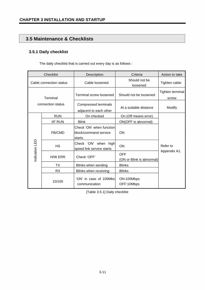
The daily checklist that is carried out every day is as follows :
Checklist Description Criteria Action to take
Cable connection status Cable loosened Should not be
loosened Tighten cable
Terminal screw loosened Should not be loosened Tighten terminal
screw Terminal
connection status Compressed terminals
adjacent to each other At a suitable distance Modify
RUN On checked On (Off means error) I/F RUN Blink ON(OFF is abnormal)
FB/CMD Check ‘ON’ when function block/command service starts.
ON
HS Check ‘ON’ when high speed link service starts.
ON
H/W ERR Check ‘OFF’ OFF (ON or Blink is abnormal)
TX Blinks when sending Blinks RX Blinks when receiving Blinks
Indi
catio
n LE
D
10/100 ‘ON’ in case of 100Mbs
communication ON:100Mbps OFF:10Mbps
Refer to Appendix A1.
[Table 3.5.1] Daily checklist

CHAPTER 3 INSTALLATION AND STARTUP
3-12
3.5.2 Regular checklist Check the following items 1~2 times every 6 months and take the required actions.
Check items How to check Criteria Action to take
Ambient temperature
0~55
Ambient moisture
Measure with thermometer/ hygrometer
5~95%RH Ambient
conditions Ambient pollution Measure corrosive gas
No corrosive gas
allowed
Adjust as specified in the
general specifications. (If used in the
panel, base the ambient criteria inside the panel)
Loosening, shaking Move communication
module Mount firmly
Module status
Dust, foreign matters Check visually Should not be
attached
Tighten screws
Terminal screw loosened
Tighten with driver Should not be
loosened Tighten screws
Closed to terminal wiring tab
Check visually At a suitable
distance Correct Connection
status
Connector loosened Check visually Should not be
loosened
Tighten connectorlocking screw
Power voltage check Measure voltage between the AC 110/220V terminals
AC 85~132V AC 170~264V
Modify power supply
[Table 3.5.2] Regular checklist
3.5.3 How to add/remove the module If the users want to change or remove the relevant module due to a hardware error or a system
change, please follow the procedure below:
1) The procedure to change the communication module (1) Turn the power of the base that the communication Module is installed to OFF. (2) Remove the network cable and connector. (3) Install the module according to the procedure in section 3.2 product setting up to
operation. Point
1) In the case of changing the FEnet I/F module, please reset the opposite device (HMI or PC). There may be no response from the opposite device because of time out of the relevant module or it may be due to a failure of communication.

CHAPTER 4 SYSTEM CONFIGURATIONS
4-1
CHAPTER 4 SYSTEM CONFIGURATIONS
4.1 Network System Configuration
4.1.1 Single system configuration
[Figure 4.1.1] GLOFA PLC Ethernet system
Hub
Hub
Desktop System Desktop System
G3Q-RY4A
RUNCPU I/F RUNFB-SERVECEHS-SERVICEGMWIN-SERVICEGLOFA-SERVICEFTP-SERVICEH/W-ERROR
10BASE5 ENABLE10BASE2 ENABLE10BASE-T LINK10BASE-T PLRTYTXRX
L 00
01
0203
04
05
06
07
COM
L 16
17
18
19
04
21
22
23
COM
08L09
1011
1213
14
15
COM
08L 25
2627
2829
30
31COM
+- DC24V
RELAYAC250V 2ADC24V 2A
PROGRAMMABLECONTROLLER
GLO
FA
GM3-PA1A
PWR
G3L-EUEA
RUNCPU I/F RUNFB-SERVECEHS-SERVICEGMWIN-SERVICEGLOFA-SERVICEFTP-SERVICEH/W-ERROR
10BASE5 ENABLE10BASE2 ENABLE10BASE-T LINK10BASE-T PLRTYTXRX
MODE
1
2345
06
7 8 9
0: ON.RUN1: TEST12: TEST2
EXT.POWER
DC IN
+12V
12G
FG
10BASE5
10BASE2
10BASE-T
RUN
GM1-CPUA
RUNSTOP
REMOTEFAIL
ERROR
PAU/REM
STOP
G3L-FUEA
MODE
0: ON.RUN1: TEST12: TEST2
X1
X10
CON1
CON2
1
2345
06
7 8 9
1
234
5
06
7 8 9
1
234
5
06
7 8 9
RUN
LAS
TOKEN
TX/RX
FAULT
G3Q-RY4A
RUNCPU I/F RUNFB-SERVECEHS-SERVICEGMWIN-SERVICEGLOFA-SERVICEFTP-SERVICEH/W-ERROR
10BASE5 ENABLE10BASE2 ENABLE10BASE-T LINK10BASE-T PLRTYTXRX
L 00
01
0203
04
05
06
07
COM
L 16
17
18
19
04
21
22
23
COM
08L09
1011
1213
14
15
COM
08L 25
2627
2829
30
31COM
+- DC24V
RELAYAC250V 2ADC24V 2A
PROGRAMMABLECONTROLLER
GLO
FA
GM3-PA1A
PWR
G3L-EUEA
RUNCPU I/F RUNFB-SERVECEHS-SERVICEGMWIN-SERVICEGLOFA-SERVICEFTP-SERVICEH/W-ERROR
10BASE5 ENABLE10BASE2 ENABLE10BASE-T LINK10BASE-T PLRTYTXRX
MODE
1
2345
06
7 8 9
0: ON.RUN1: TEST12: TEST2
EXT.POWER
DC IN
+12V
12G
FG
10BASE5
10BASE2
10BASE-T
RUN
GM1-CPUA
RUNSTOP
REMOTEFAIL
ERROR
PAU/REM
STOP
G3L-FUEA
MODE
0: ON.RUN1: TEST12: TEST2
X1
X10
CON1
CON2
1
2345
06
78 9
1
234
5
06
78 9
1
234
5
06
7 8 9
RUN
LAS
TOKEN
TX/RX
FAULT
G3Q-RY4A
RUNCPU I/F RUNFB-SERVECEHS-SERVICEGMWIN-SERVICEGLOFA-SERVICEFTP-SERVICEH/W-ERROR
10BASE5 ENABLE10BASE2 ENABLE10BASE-T LINK10BASE-T PLRTYTXRX
L 00
01
0203
04
05
06
07
COM
L 16
17
18
19
04
21
22
23
COM
08L09
1011
1213
14
15
COM
08L 25
2627
2829
30
31COM
+- DC24V
RELAYAC250V 2ADC24V 2A
PROGRAMMABLECONTROLLER
GLO
FA
GM3-PA1A
PWR
G3L-EUEA
RUNCPU I/F RUNFB-SERVECEHS-SERVICEGMWIN-SERVICEGLOFA-SERVICEFTP-SERVICEH/W-ERROR
10BASE5 ENABLE10BASE2 ENABLE10BASE-T LINK10BASE-T PLRTYTXRX
MODE
1
2345
06
7 8 9
0: ON.RUN1: TEST12: TEST2
EXT.POWER
DC IN
+12V
12G
FG
10BASE5
10BASE2
10BASE-T
RUN
GM1-CPUA
RUNSTOP
REMOTEFAIL
ERROR
PAU/REM
STOP
G3L-FUEA
MODE
0: ON.RUN1: TEST12: TEST2
X1
X10
CON1
CON2
1
2345
06
7 8 9
1
234
5
06
7 8 9
1
234
5
06
7 8 9
RUN
LAS
TOKEN
TX/RX
FAULT
이더넷 망(네트워크1)
GLOFA PLC A210.206.91.188
GLOFA PLC B210.206.91.189
GLOFA PLC C210.206.91.190
Desktop System Desktop System
G3Q-RY4A
RUNCPU I/F RUNFB-SERVECEHS-SERVICEGMWIN-SERVICEGLOFA-SERVICEFTP-SERVICEH/W-ERROR
10BASE5 ENABLE10BASE2 ENABLE10BASE-T LINK10BASE-T PLRTYTXRX
L00
01
0203
04
05
06
07
COM
L 16
17
18
19
04
21
22
23
COM
08L09
1011
1213
14
15
COM
08L 25
2627
2829
30
31COM
+- DC24V
RELAYAC250V 2ADC24V 2A
PROGRAMMABLECONTROLLER
GLO
FA
GM3-PA1A
PWR
G3L-EUEA
RUNCPU I/F RUNFB-SERVECEHS-SERVICEGMWIN-SERVICEGLOFA-SERVICEFTP-SERVICEH/W-ERROR
10BASE5 ENABLE10BASE2 ENABLE10BASE-T LINK10BASE-T PLRTYTXRX
MODE
1
2345
06
7 8 9
0: ON.RUN1: TEST12: TEST2
EXT.POWER
DC IN
+12V
12G
FG
10BASE5
10BASE2
10BASE-T
RUN
GM1-CPUA
RUNSTOP
REMOTEFAIL
ERROR
PAU/REM
STOP
G3L-FUEA
MODE
0: ON.RUN1: TEST12: TEST2
X1
X10
CON1
CON2
1
2345
06
7 8 9
1
234
5
06
7 8 9
1
234
5
06
7 89
RUN
LAS
TOKEN
TX/RX
FAULT
GLOFA PLC A210.206.91.191
GLOFA PLC B210.206.91.192
GLOFA PLC C210.206.91.193
internet
라우터 또는 게이트 웨이
라우터 또는 게이트 웨이
광역 감시 시스템1191.100.105.1
광역 감시 시스템2191.100.105.2
지역 감시 시스템1210.206.91.194
지역 감시 시스템2210.206.91.195
공중망
Router or Gateway
Wide band monitoring system 2191.100.105.2
Wideband monitoring system 1 191.100.105.1
Public Network
Router or Gateway
Ethernet( Network 1)
Local monitoring system 1 210.206.91.194
Local monitoring system 2 210.206.91.195
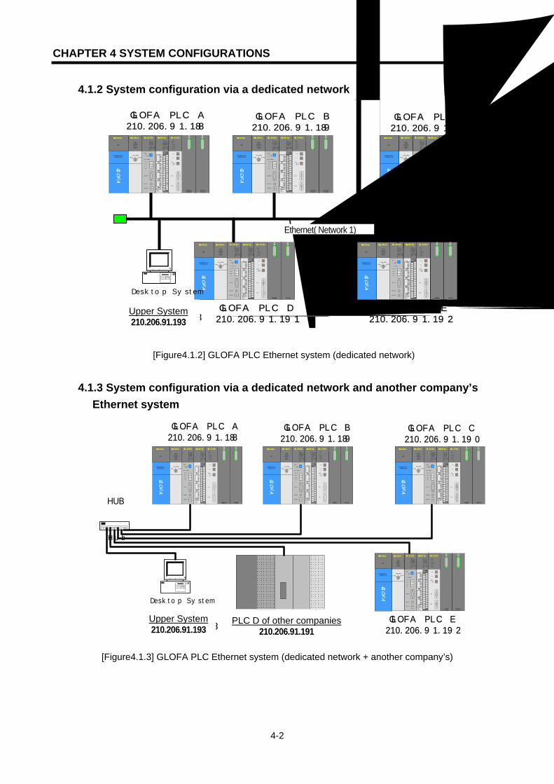
CHAPTER 4 SYSTEM CONFIGURATIONS
4-2
4.1.2 System configuration via a dedicated network
[Figure4.1.2] GLOFA PLC Ethernet system (dedicated network)
4.1.3 System configuration via a dedicated network and another company’s Ethernet system
[Figure4.1.3] GLOFA PLC Ethernet system (dedicated network + another company’s)
G3Q-RY4ARUNCPU I/F RUNFB-SERVECEHS-SERVICEGMWIN-SERVICEGLOFA-SERVICEFTP-SERVICEH/W-ERROR
10BASE5 ENABLE10BASE2 ENABLE10BASE-T LINK10BASE-T PLRTYTXRX
L00
01
0203
04
05
06
07
COM
L16
17
18
19
04
21
22
23
COM
08L 09
1011
1213
14
15
COM
08L 25
2627
2829
30
31COM
+- DC24V
RELAYAC250V 2ADC24V 2A
PROGRAMMABLECONTROLLER
GLO
FA
GM3-PA1A
PWR
G3L-EUEARUNCPU I/F RUNFB-SERVECEHS-SERVICEGMWIN-SERVICEGLOFA-SERVICEFTP-SERVICEH/W-ERROR
10BASE5 ENABLE10BASE2 ENABLE10BASE-T LINK10BASE-T PLRTYTXRX
MODE
1
2345
06
7 8 9
0: ON.RUN1: TEST12: TEST2
EXT.POWER
DC IN
+12V
12G
FG
10BASE5
10BASE2
10BASE-T
RUN
GM1-CPUA
RUNSTOP
REMOTEFAIL
ERROR
PAU/REM
STOP
G3L-FUEA
MODE
0: ON.RUN1: TEST12: TEST2
X1
X10
CON1
CON2
12345
06
7 8 9
1
2345
06
7 8 9
1
2345
06
7 8 9
RUN
LAS
TOKEN
TX/RX
FAULT
이더넷 망(네트워크1)
GLOFA PLC B210.206.91.189
GLOFA PLC C210.206.91.190
G3Q-RY4ARUNCPU I/F RUNFB-SERVECEHS-SERVICEGMWIN-SERVICEGLOFA-SERVICEFTP-SERVICEH/W-ERROR
10BASE5 ENABLE10BASE2 ENABLE10BASE-T LINK10BASE-T PLRTYTXRX
L00
01
0203
04
05
06
07
COM
L16
17
18
19
04
21
22
23
COM
08L 09
1011
1213
14
15
COM
08L 25
2627
2829
30
31COM
+- DC24V
RELAYAC250V 2ADC24V 2A
PROGRAMMABLECONTROLLER
GLO
FA
GM3-PA1A
PWR
G3L-EUEARUNCPU I/F RUNFB-SERVECEHS-SERVICEGMWIN-SERVICEGLOFA-SERVICEFTP-SERVICEH/W-ERROR
10BASE5 ENABLE10BASE2 ENABLE10BASE-T LINK10BASE-T PLRTYTXRX
MODE
1
2345
06
7 8 9
0: ON.RUN1: TEST12: TEST2
EXT.POWER
DC IN
+12V
12G
FG
10BASE5
10BASE2
10BASE-T
RUN
GM1-CPUA
RUNSTOP
REMOTEFAIL
ERROR
PAU/REM
STOP
G3L-FUEA
MODE
0: ON.RUN1: TEST12: TEST2
X1
X10
CON1
CON2
12345
06
7 8 9
1
2345
06
7 8 9
1
2345
06
7 89
RUN
LAS
TOKEN
TX/RX
FAULT
GLOFA PLC A210.206.91.188
G3Q-RY4A
RUNCPU I/F RUNFB-SERVECEHS-SERVICEGMWIN-SERVICEGLOFA-SERVICEFTP-SERVICEH/W-ERROR
10BASE5 ENABLE10BASE2 ENABLE10BASE-T LINK10BASE-T PLRTYTXRX
L00
01
0203
04
05
06
07
COM
L16
17
1819
04
21
22
23
COM
08L 09
1011
1213
14
15
COM
08L 25
2627
2829
30
31COM
+- DC24V
RELAYAC250V 2ADC24V 2A
PROGRAMMABLECONTROLLER
GLO
FA
GM3-PA1A
PWR
G3L-EUEA
RUNCPU I/F RUNFB-SERVECEHS-SERVICEGMWIN-SERVICEGLOFA-SERVICEFTP-SERVICEH/W-ERROR
10BASE5 ENABLE10BASE2 ENABLE10BASE-T LINK10BASE-T PLRTYTXRX
MODE
1
2345
06
7 8 9
0: ON.RUN1: TEST12: TEST2
EXT.POWER
DC IN
+12V
12G
FG
10BASE5
10BASE2
10BASE-T
RUN
GM1-CPUA
RUNSTOP
REMOTEFAIL
ERROR
PAU/REM
STOP
G3L-FUEA
MODE
0: ON.RUN1: TEST12: TEST2
X1
X10
CON1
CON2
1
2345
06
7 8 9
1
2345
06
7 8 9
1
2345
06
7 89
RUN
LAS
TOKEN
TX/RX
FAULT
GLOFA PLC D210.206.91.191
G3Q-RY4A
RUNCPU I/F RUNFB-SERVECEHS-SERVICEGMWIN-SERVICEGLOFA-SERVICEFTP-SERVICEH/W-ERROR
10BASE5 ENABLE10BASE2 ENABLE10BASE-T LINK10BASE-T PLRTYTXRX
L00
01
0203
04
05
06
07
COM
L16
17
1819
04
21
22
23
COM
08L 09
1011
1213
14
15
COM
08L 25
2627
2829
30
31COM
+- DC24V
RELAYAC250V 2ADC24V 2A
PROGRAMMABLECONTROLLER
GLO
FA
GM3-PA1A
PWR
G3L-EUEA
RUNCPU I/F RUNFB-SERVECEHS-SERVICEGMWIN-SERVICEGLOFA-SERVICEFTP-SERVICEH/W-ERROR
10BASE5 ENABLE10BASE2 ENABLE10BASE-T LINK10BASE-T PLRTYTXRX
MODE
1
2345
06
7 8 9
0: ON.RUN1: TEST12: TEST2
EXT.POWER
DC IN
+12V
12G
FG
10BASE5
10BASE2
10BASE-T
RUN
GM1-CPUA
RUNSTOP
REMOTEFAIL
ERROR
PAU/REM
STOP
G3L-FUEA
MODE
0: ON.RUN1: TEST12: TEST2
X1
X10
CON1
CON2
1
2345
06
7 8 9
1
2345
06
7 8 9
1
2345
06
7 89
RUN
LAS
TOKEN
TX/RX
FAULT
GLOFA PLC E210.206.91.192
상위 시스템210.206.91.193
Desktop System
Upper System 210.206.91.193
Ethernet( Network 1)
G3Q-RY4ARUNCPU I/F RUNFB-SERVECEHS-SERVICEGMWIN-SERVICEGLOFA-SERVICEFTP-SERVICEH/W-ERROR
10BASE5 ENABLE10BASE2 ENABLE10BASE-T LINK10BASE-T PLRTYTXRX
L00
01
0203
04
05
06
07
COM
L16
17
18
19
04
21
22
23
COM
08L 09
1011
1213
14
15
COM
08L 25
2627
2829
30
31COM
+- DC24V
RELAYAC250V 2ADC24V 2A
PROGRAMMABLECONTROLLER
GLO
FA
GM3-PA1A
PWR
G3L-EUEARUNCPU I/F RUNFB-SERVECEHS-SERVICEGMWIN-SERVICEGLOFA-SERVICEFTP-SERVICEH/W-ERROR
10BASE5 ENABLE10BASE2 ENABLE10BASE-T LINK10BASE-T PLRTYTXRX
MODE
1
2345
06
7 89
0: ON.RUN1: TEST12: TEST2
EXT.POWER
DC IN
+12V
12G
FG
10BASE5
10BASE2
10BASE-T
RUN
GM1-CPUA
RUNSTOP
REMOTEFAIL
ERROR
PAU/REM
STOP
G3L-FUEA
MODE
0: ON.RUN1: TEST12: TEST2
X1
X10
CON1
CON2
1234
5
06
7 89
1
234
5
06
7 89
1
234
5
06
7 89
RUN
LAS
TOKEN
TX/RX
FAULT
G3Q-RY4ARUNCPU I/F RUNFB-SERVECEHS-SERVICEGMWIN-SERVICEGLOFA-SERVICEFTP-SERVICEH/W-ERROR
10BASE5 ENABLE10BASE2 ENABLE10BASE-T LINK10BASE-T PLRTYTXRX
L00
01
0203
04
05
06
07
COM
L16
17
18
19
04
21
22
23
COM
08L 09
1011
1213
14
15
COM
08L 25
2627
2829
30
31COM
+- DC24V
RELAYAC250V 2ADC24V 2A
PROGRAMMABLECONTROLLER
GLO
FA
GM3-PA1A
PWR
G3L-EUEARUNCPU I/F RUNFB-SERVECEHS-SERVICEGMWIN-SERVICEGLOFA-SERVICEFTP-SERVICEH/W-ERROR
10BASE5 ENABLE10BASE2 ENABLE10BASE-T LINK10BASE-T PLRTYTXRX
MODE
1
2345
06
7 89
0: ON.RUN1: TEST12: TEST2
EXT.POWER
DC IN
+12V
12G
FG
10BASE5
10BASE2
10BASE-T
RUN
GM1-CPUA
RUNSTOP
REMOTEFAIL
ERROR
PAU/REM
STOP
G3L-FUEA
MODE
0: ON.RUN1: TEST12: TEST2
X1
X10
CON1
CON2
12345
06
7 89
1
2345
06
7 89
1
234
5
06
7 89
RUN
LAS
TOKEN
TX/RX
FAULT
GLOFA PLC B210.206.91.189
GLOFA PLC C210.206.91.190
G3Q-RY4ARUNCPU I/F RUNFB-SERVECEHS-SERVICEGMWIN-SERVICEGLOFA-SERVICEFTP-SERVICEH/W-ERROR
10BASE5 ENABLE10BASE2 ENABLE10BASE-T LINK10BASE-T PLRTYTXRX
L00
01
0203
04
05
06
07
COM
L16
17
18
19
04
21
22
23
COM
08L 09
1011
1213
14
15
COM
08L 25
2627
2829
30
31COM
+- DC24V
RELAYAC250V 2ADC24V 2A
PROGRAMMABLECONTROLLER
GLO
FA
GM3-PA1A
PWR
G3L-EUEARUNCPU I/F RUNFB-SERVECEHS-SERVICEGMWIN-SERVICEGLOFA-SERVICEFTP-SERVICEH/W-ERROR
10BASE5 ENABLE10BASE2 ENABLE10BASE-T LINK10BASE-T PLRTYTXRX
MODE
1
2345
06
7 89
0: ON.RUN1: TEST12: TEST2
EXT.POWER
DC IN
+12V
12G
FG
10BASE5
10BASE2
10BASE-T
RUN
GM1-CPUA
RUNSTOP
REMOTEFAIL
ERROR
PAU/REM
STOP
G3L-FUEA
MODE
0: ON.RUN1: TEST12: TEST2
X1
X10
CON1
CON2
12345
06
7 8 9
1
2345
06
7 8 9
1
234
5
06
7 89
RUN
LAS
TOKEN
TX/RX
FAULT
GLOFA PLC A210.206.91.188
타사 PLC D210.206.91.191
G3Q-RY4A
RUNCPU I/F RUNFB-SERVECEHS-SERVICEGMWIN-SERVICEGLOFA-SERVICEFTP-SERVICEH/W-ERROR
10BASE5 ENABLE10BASE2 ENABLE10BASE-T LINK10BASE-T PLRTYTXRX
L00
01
0203
04
05
06
07
COM
L16
17
1819
04
21
22
23
COM
08L 09
1011
1213
14
15
COM
08L 25
2627
2829
30
31COM
+- DC24V
RELAYAC250V 2ADC24V 2A
PROGRAMMABLECONTROLLER
GLO
FA
GM3-PA1A
PWR
G3L-EUEA
RUNCPU I/F RUNFB-SERVECEHS-SERVICEGMWIN-SERVICEGLOFA-SERVICEFTP-SERVICEH/W-ERROR
10BASE5 ENABLE10BASE2 ENABLE10BASE-T LINK10BASE-T PLRTYTXRX
MODE
1
2345
06
7 89
0: ON.RUN1: TEST12: TEST2
EXT.POWER
DC IN
+12V
12G
FG
10BASE5
10BASE2
10BASE-T
RUN
GM1-CPUA
RUNSTOP
REMOTEFAIL
ERROR
PAU/REM
STOP
G3L-FUEA
MODE
0: ON.RUN1: TEST12: TEST2
X1
X10
CON1
CON2
1
234
5
06
7 89
1
234
5
06
7 89
1
2345
06
7 89
RUN
LAS
TOKEN
TX/RX
FAULT
GLOFA PLC E210.206.91.192
상위 시스템210.206.91.193
Desktop System
Hub
허브 HUB
Upper System 210.206.91.193
PLC D of other companies210.206.91.191

CHAPTER 4 SYSTEM CONFIGURATIONS
4-3
4.1.4 System configuration via a public network and a dedicated network
[Figure4.1.4] GLOFA PLC Ethernet system (public network + dedicated network)
Hub
Hub
Desktop System Desktop System
G3Q-RY4ARUNCPU I/F RUNFB-SERVECEHS-SERVICEGMWIN-SERVICEGLOFA-SERVICEFTP-SERVICEH/W-ERROR
10BASE5 ENABLE10BASE2 ENABLE10BASE-T LINK10BASE-T PLRTYTXRX
L00
01
0203
04
05
06
07
COM
L16
17
18
19
04
21
22
23
COM
08L 09
1011
1213
14
15
COM
08L 25
2627
2829
30
31COM
+- DC24V
RELAYAC250V 2ADC24V 2A
PROGRAMMABLECONTROLLER
GLO
FA
GM3-PA1A
PWR
G3L-EUEA
RUNCPU I/F RUNFB-SERVECEHS-SERVICEGMWIN-SERVICEGLOFA-SERVICEFTP-SERVICEH/W-ERROR
10BASE5 ENABLE10BASE2 ENABLE10BASE-T LINK10BASE-T PLRTYTXRX
MODE
1
2345
06
7 8 9
0: ON.RUN1: TEST12: TEST2
EXT.POWER
DC IN
+12V
12G
FG
10BASE5
10BASE2
10BASE-T
RUN
GM1-CPUA
RUNSTOP
REMOTEFAIL
ERROR
PAU/REM
STOP
G3L-FUEA
MODE
0: ON.RUN1: TEST12: TEST2
X1
X10
CON1
CON2
1
234
5
06
7 89
1
234
5
06
7 89
1
2345
06
7 89
RUN
LAS
TOKEN
TX/RX
FAULT
이더넷 망(네트워크1)
GLOFA PLC A210.206.91.188
GLOFA PLC B210.206.91.189
GLOFA PLC C210.206.91.190
Desktop System Desktop System
internet
라우터 또는 게이트 웨이
라우터 또는 게이트 웨이
광역 감시 시스템1191.100.105.1
광역 감시 시스템2191.100.105.2
지역 감시 시스템1210.206.91.194
지역 감시 시스템2210.206.91.195
공중망
Router or Gateway
Public Network Router or Gateway
Wideband monitoring system 2191.100.105.2
Wideband monitoring system 1191.100.105.1
Ethernet (Network 1)
Local Monitoring System
10.206.91.194
Local Monitoring System
10.206.91.194

CHAPTER 4 SYSTEM CONFIGURATIONS
4-4
4.1.5 System configuration via a public network, dedicated network and another company’s Ethernet system
[Figure4.1.5] GLOFA PLC Ethernet system (public network + dedicated network + another company’s
system)
Hub
Hub
Desktop System Desktop System
G3Q-RY4ARUNCPU I/F RUNFB-SERVECEHS-SERVICEGMWIN-SERVICEGLOFA-SERVICEFTP-SERVICEH/W-ERROR
10BASE5 ENABLE10BASE2 ENABLE10BASE-T LINK10BASE-T PLRTYTXRX
L00
01
0203
04
05
06
07
COM
L16
17
18
19
04
21
22
23
COM
08L 09
1011
1213
14
15
COM
08L 25
2627
2829
30
31COM
+- DC24V
RELAYAC250V 2ADC24V 2A
PROGRAMMABLECONTROLLER
GLO
FA
GM3-PA1A
PWR
G3L-EUEA
RUNCPU I/F RUNFB-SERVECEHS-SERVICEGMWIN-SERVICEGLOFA-SERVICEFTP-SERVICEH/W-ERROR
10BASE5 ENABLE10BASE2 ENABLE10BASE-T LINK10BASE-T PLRTYTXRX
MODE
1
2345
06
7 8 9
0: ON.RUN1: TEST12: TEST2
EXT.POWER
DC IN
+12V
12G
FG
10BASE5
10BASE2
10BASE-T
RUN
GM1-CPUA
RUNSTOP
REMOTEFAIL
ERROR
PAU/REM
STOP
G3L-FUEA
MODE
0: ON.RUN1: TEST12: TEST2
X1
X10
CON1
CON2
1
234
5
06
7 8 9
1
234
5
06
7 8 9
1
2345
06
7 89
RUN
LAS
TOKEN
TX/RX
FAULT
G3Q-RY4ARUNCPU I/F RUNFB-SERVECEHS-SERVICEGMWIN-SERVICEGLOFA-SERVICEFTP-SERVICEH/W-ERROR
10BASE5 ENABLE10BASE2 ENABLE10BASE-T LINK10BASE-T PLRTYTXRX
L00
01
0203
04
05
06
07
COM
L16
17
18
19
04
21
22
23
COM
08L 09
1011
1213
14
15
COM
08L 25
2627
2829
30
31COM
+- DC24V
RELAYAC250V 2ADC24V 2A
PROGRAMMABLECONTROLLER
GLO
FA
GM3-PA1A
PWR
G3L-EUEA
RUNCPU I/F RUNFB-SERVECEHS-SERVICEGMWIN-SERVICEGLOFA-SERVICEFTP-SERVICEH/W-ERROR
10BASE5 ENABLE10BASE2 ENABLE10BASE-T LINK10BASE-T PLRTYTXRX
MODE
1
2345
06
7 89
0: ON.RUN1: TEST12: TEST2
EXT.POWER
DC IN
+12V
12G
FG
10BASE5
10BASE2
10BASE-T
RUN
GM1-CPUA
RUNSTOP
REMOTEFAIL
ERROR
PAU/REM
STOP
G3L-FUEA
MODE
0: ON.RUN1: TEST12: TEST2
X1
X10
CON1
CON2
1
2345
06
7 89
1
2345
06
7 89
1
2345
06
7 89
RUN
LAS
TOKEN
TX/RX
FAULT
이더넷 망(네트워크1)
GLOFA PLC A210.206.91.188
GLOFA PLC B210.206.91.189
GLOFA PLC C210.206.91.190
Desktop System Desktop System
internet
라우터 또는 게이트 웨이
라우터 또는 게이트 웨이
광역 감시 시스템1191.100.105.1
광역 감시 시스템2191.100.105.2
지역 감시 시스템1210.206.91.194
지역 감시 시스템2210.206.91.195
공중망
타사 PLC D210.206.91.191
Local monitoring system 1 210.206.91.194
Local monitoring system 2 210.206.91.195 PLC D of other companies
210.206.91.191
Etherne t (Network 1)
Router or Gateway
Public Network Router or Gateway
Wideband monitoring system 2191.100.105.2
Wideband monitoring system 1191.100.105.1
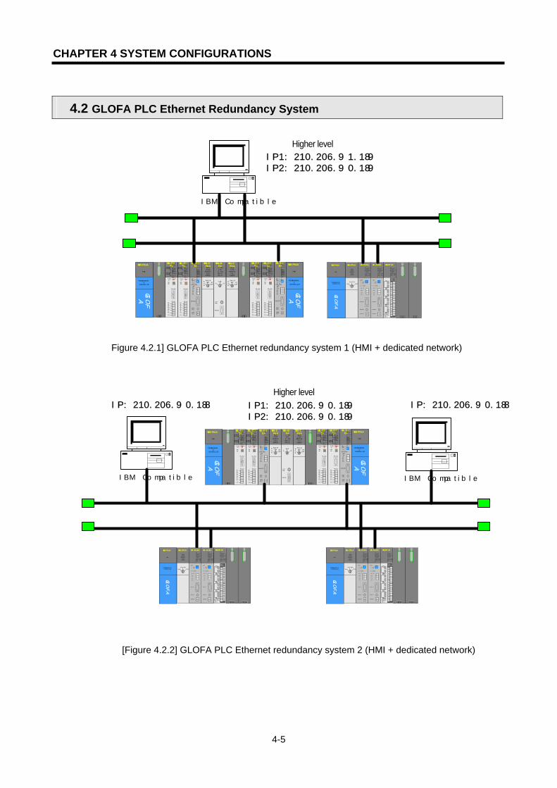
CHAPTER 4 SYSTEM CONFIGURATIONS
4-5
4.2 GLOFA PLC Ethernet Redundancy System
[Figure 4.2.1] GLOFA PLC Ethernet redundancy system 1 (HMI + dedicated network)
[Figure 4.2.2] GLOFA PLC Ethernet redundancy system 2 (HMI + dedicated network)
G3L-EUEA
RUNCPU I/F RUNFB-SERVECEHS-SERVICEGMWIN-SERVICEGLOFA-SERVICEFTP-SERVICEH/W-ERROR
10BASE5 ENABLE10BASE2 ENABLE10BASE-T LINK10BASE-T PLRTYTXRXMO
DE12345
06 7890: ON.RUN1: TEST12: TEST2EXT.POWER
DC IN
+12V12GFG
10BASE5
10BASE2
10BASE-T
RUN
GM1-CPUARUNSTOP
REMOTEFAIL
ERROR
PAU/REM ST
OPA
GM1-DIFA
A SELA+B
B AELCPU-ACPU-B
A+B
B
EXTPWR
RS232C
RUN
GM1-CPUARUNSTOP
REMOTEFAIL
ERROR
PAU/REM ST
OP
PROGRAMMABLE
CONTROLLER
GLO
FA
GM3-PA1A
PWR
G3L-EUEA
RUN/BPSTX/BPSRS/BPSACK/DATA-BITNAK/PARITYERR/EVEN-ODDNODEM/STOP-BITSYS-RUN
MODE
RS-232C
12345
06 789
DISPLAY
RS-422RDA
RDBSDA
SDB
SG
FG
RUN/BPSTX/BPSRX/BPSACK/DATA-BITNAK/PARITYERR/EVEN-ODDRS-485/STOP-BITSYS-ERROR
RS-232C
RS-422
G3L-EUEA
RUN/BPSTX/BPSRS/BPSACK/DATA-BITNAK/PARITYERR/EVEN-ODDNODEM/STOP-BITSYS-RUN
MODE
RS-232C
1234
5 06 789
DISPLAY
RS-422
RDA
RDBSDA
SDBSG
FG
RUN/BPSTX/BPSRX/BPSACK/DATA-BITNAK/PARITYERR/EVEN-ODDRS-485/STOP-BITSYS-ERROR
RS-232C
RS-422
G3L-EUEA
RUNCPU I/F RUNFB-SERVECEHS-SERVICEGMWIN-SERVICEGLOFA-SERVICEFTP-SERVICEH/W-ERROR
10BASE5 ENABLE10BASE2 ENABLE10BASE-T LINK10BASE-T PLRTYTXRXMO
DE1234
5 067890: ON.RUN1: TEST12: TEST2EXT.POWER
DC IN
+12V12GFG
10BASE5
10BASE2
10BASE-T
PROGRAMMABLE
CONTROLLER
GLO
FA
GM3-PA1A
PWR
G3L-EUEA
RUN/BPSTX/BPSRS/BPSACK/DATA-BITNAK/PARITYERR/EVEN-ODDNODEM/STOP-BITSYS-RUN
MODE
RS-232C
1234
5 06789
DISPLAY
RS-422
RDARDBSDASDB
SG
FG
RUN/BPSTX/BPSRX/BPSACK/DATA-BITNAK/PARITYERR/EVEN-ODDRS-485/STOP-BITSYS-ERROR
RS-232C
RS-422
G3L-EUEA
RUN/BPSTX/BPSRS/BPSACK/DATA-BITNAK/PARITYERR/EVEN-ODDNODEM/STOP-BITSYS-RUN
MODE
RS-232C
1234
5 06 789
DISPLAY
RS-422
RDARDBSDASDB
SG
FG
RUN/BPSTX/BPSRX/BPSACK/DATA-BITNAK/PARITYERR/EVEN-ODDRS-485/STOP-BITSYS-ERROR
RS-232C
RS-422
G3Q-RY4ARUNCPU I/F RUNFB-SERVECEHS-SERVICE
GMWIN-SERVICEGLOFA-SERVICEFTP-SERVICEH/W-ERROR
10BASE5 ENABLE10BASE2 ENABLE10BASE-T LINK10BASE-T PLRTYTXRX
L00
01
02
03
04
05
06
07
COM
L16
17
18
19
04
21
22
23
COM
08L09
1011
1213
14
15
COM
08L 25
26
27
2829
30
31
COM
+- DC24V
RELAYAC250V 2ADC24V 2A
PROGRAMMABLECONTROLLER
GLO
FA
GM3-PA1A
PWR
RUN
GM1-CPUA
RUNSTOP
REMOTEFAIL
ERROR
PAU/REM
STOP
G3L-EUEA
RUNCPU I/F RUNFB-SERVECEHS-SERVICEGMWIN-SERVICEGLOFA-SERVICEFTP-SERVICEH/W-ERROR
10BASE5 ENABLE10BASE2 ENABLE10BASE-T LINK10BASE-T PLRTYTXRX
MODE
1
2345
06
7 8 9
0: ON.RUN1: TEST12: TEST2
EXT.POWER
DC IN
+12V
12G
FG
10BASE5
10BASE2
10BASE-T
G3L-EUEA
RUNCPU I/F RUNFB-SERVECEHS-SERVICEGMWIN-SERVICEGLOFA-SERVICEFTP-SERVICEH/W-ERROR
10BASE5 ENABLE10BASE2 ENABLE10BASE-T LINK10BASE-T PLRTYTXRX
MODE
1
2345
06
7 89
0: ON.RUN1: TEST12: TEST2
EXT.POWER
DC IN
+12V
12G
FG
10BASE5
10BASE2
10BASE-T
상위IP1:210.206.91.189IP2:210.206.90.189
IBM Compatible
G3L-EUEA
RUNCPU I/F RUNFB-SERVECEHS-SERVICEGMWIN-SERVICEGLOFA-SERVICEFTP-SERVICEH/W-ERROR
10BASE5 ENABLE10BASE2 ENABLE10BASE-T LINK10BASE-T PLRTYTXRXMO
DE1234
5 06 7890: ON.RUN1: TEST12: TEST2EXT.POWER
DC IN
+12V12GFG
10BASE5
10BASE2
10BASE-T
RUN
GM1-CPUARUNSTOP
REMOTEFAIL
ERROR
PAU/REM ST
OPA
GM1-DIFA
A SELA+B
B AELCPU-ACPU-B
A+B
B
EXTPWR
RS232C
RUN
GM1-CPUARUNSTOP
REMOTEFAIL
ERROR
PAU/REM ST
OP
PROGRAMMABLE
CONTROLLER
GLO
FA
GM3-PA1A
PWR
G3L-EUEA
RUN/BPSTX/BPSRS/BPSACK/DATA-BITNAK/PARITYERR/EVEN-ODDNODEM/STOP-BITSYS-RUN
MODE
RS-232C
12345
06 789
DISPLAY
RS-422
RDA
RDBSDA
SDB
SG
FG
RUN/BPSTX/BPSRX/BPSACK/DATA-BITNAK/PARITYERR/EVEN-ODDRS-485/STOP-BITSYS-ERROR
RS-232C
RS-422
G3L-EUEA
RUN/BPSTX/BPSRS/BPSACK/DATA-BITNAK/PARITYERR/EVEN-ODDNODEM/STOP-BITSYS-RUN
MODE
RS-232C
1234
5 06 789
DISPLAY
RS-422RDARDBSDASDBSG
FG
RUN/BPSTX/BPSRX/BPSACK/DATA-BITNAK/PARITYERR/EVEN-ODDRS-485/STOP-BITSYS-ERROR
RS-232C
RS-422
G3L-EUEA
RUNCPU I/F RUNFB-SERVECEHS-SERVICEGMWIN-SERVICEGLOFA-SERVICEFTP-SERVICEH/W-ERROR
10BASE5 ENABLE10BASE2 ENABLE10BASE-T LINK10BASE-T PLRTYTXRXMO
DE12345
067890: ON.RUN1: TEST12: TEST2EXT.POWER
DC IN
+12V12GFG
10BASE5
10BASE2
10BASE-T
PROGRAMMABLE
CONTROLLER
GLO
FA
GM3-PA1A
PWR
G3L-EUEA
RUN/BPSTX/BPSRS/BPSACK/DATA-BITNAK/PARITYERR/EVEN-ODDNODEM/STOP-BITSYS-RUN
MODE
RS-232C
1234
5 06789
DISPLAY
RS-422RDARDBSDASDB
SG
FG
RUN/BPSTX/BPSRX/BPSACK/DATA-BITNAK/PARITYERR/EVEN-ODDRS-485/STOP-BITSYS-ERROR
RS-232C
RS-422
G3L-EUEA
RUN/BPSTX/BPSRS/BPSACK/DATA-BITNAK/PARITYERR/EVEN-ODDNODEM/STOP-BITSYS-RUN
MODE
RS-232C
1234
5 06789
DISPLAY
RS-422
RDARDBSDASDB
SG
FG
RUN/BPSTX/BPSRX/BPSACK/DATA-BITNAK/PARITYERR/EVEN-ODDRS-485/STOP-BITSYS-ERROR
RS-232C
RS-422
G3Q-RY4ARUNCPU I/F RUNFB-SERVECEHS-SERVICEGMWIN-SERVICEGLOFA-SERVICEFTP-SERVICEH/W-ERROR
10BASE5 ENABLE10BASE2 ENABLE10BASE-T LINK10BASE-T PLRTYTXRX
L00
01
02
03
04
05
06
07
COM
L16
17
18
19
04
21
22
23
COM
08L09
10
11
1213
14
15
COM
08L 25
2627
2829
30
31
COM
+- DC24V
RELAYAC250V 2ADC24V 2A
PROGRAMMABLECONTROLLER
GLO
FA
GM3-PA1A
PWR
RUN
GM1-CPUA
RUNSTOP
REMOTEFAIL
ERROR
PAU/REM
STOP
G3L-EUEARUNCPU I/F RUNFB-SERVECEHS-SERVICEGMWIN-SERVICEGLOFA-SERVICEFTP-SERVICE
H/W-ERROR
10BASE5 ENABLE10BASE2 ENABLE10BASE-T LINK10BASE-T PLRTYTXRX
MODE
1
2345
06
7 8 9
0: ON.RUN1: TEST12: TEST2
EXT.POWER
DC IN
+12V
12G
FG
10BASE5
10BASE2
10BASE-T
G3L-EUEARUNCPU I/F RUNFB-SERVECEHS-SERVICEGMWIN-SERVICEGLOFA-SERVICEFTP-SERVICE
H/W-ERROR
10BASE5 ENABLE10BASE2 ENABLE10BASE-T LINK10BASE-T PLRTYTXRX
MODE
1
2345
06
7 8 9
0: ON.RUN1: TEST12: TEST2
EXT.POWER
DC IN
+12V
12G
FG
10BASE5
10BASE2
10BASE-T
상위IP1:210.206.90.189IP2:210.206.90.189
G3Q-RY4ARUNCPU I/F RUNFB-SERVECEHS-SERVICEGMWIN-SERVICEGLOFA-SERVICEFTP-SERVICEH/W-ERROR
10BASE5 ENABLE10BASE2 ENABLE10BASE-T LINK10BASE-T PLRTYTXRX
L00
01
02
03
04
05
06
07
COM
L16
17
18
19
04
21
22
23
COM
08L09
10
11
1213
14
15
COM
08L 25
2627
2829
30
31
COM
+- DC24V
RELAYAC250V 2ADC24V 2A
PROGRAMMABLECONTROLLER
GLO
FA
GM3-PA1A
PWR
RUN
GM1-CPUA
RUNSTOP
REMOTEFAIL
ERROR
PAU/REM
STOP
G3L-EUEARUNCPU I/F RUNFB-SERVECEHS-SERVICEGMWIN-SERVICEGLOFA-SERVICEFTP-SERVICE
H/W-ERROR
10BASE5 ENABLE10BASE2 ENABLE10BASE-T LINK10BASE-T PLRTYTXRX
MODE
1
2345
06
7 8 9
0: ON.RUN1: TEST12: TEST2
EXT.POWER
DC IN
+12V
12G
FG
10BASE5
10BASE2
10BASE-T
G3L-EUEARUNCPU I/F RUNFB-SERVECEHS-SERVICEGMWIN-SERVICEGLOFA-SERVICEFTP-SERVICE
H/W-ERROR
10BASE5 ENABLE10BASE2 ENABLE10BASE-T LINK10BASE-T PLRTYTXRX
MODE
1
2345
06
7 8 9
0: ON.RUN1: TEST12: TEST2
EXT.POWER
DC IN
+12V
12G
FG
10BASE5
10BASE2
10BASE-T
IBM Compatible IBM Compatible
IP:210.206.90.188 IP:210.206.90.188
Higher level
Higher level
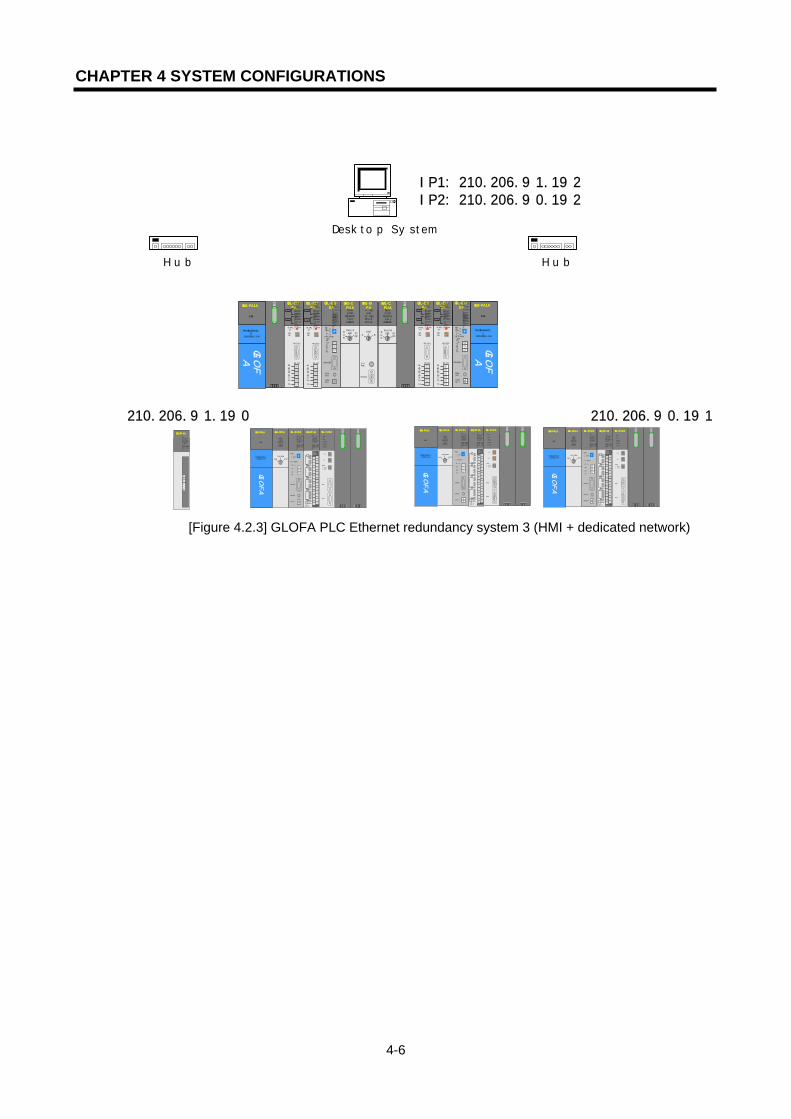
CHAPTER 4 SYSTEM CONFIGURATIONS
4-6
[Figure 4.2.3] GLOFA PLC Ethernet redundancy system 3 (HMI + dedicated network)
상위IP1:210.206.91.192IP2:210.206.90.192
210.206.91.190 210.206.90.191
G3L-EUEA
RUNCPU I/F RUNFB-SERVECEHS-SERVICEGMWIN-SERVICEGLOFA-SERVICEFTP-SERVICEH/W-ERROR
10BASE5 ENABLE10BASE2 ENABLE10BASE-T LINK10BASE-T PLRTYTXRXMO
DE1234
5 067890: ON.RUN1: TEST12: TEST2EXT.POWER
DC IN
+12V12GFG
10BASE5
10BASE2
10BASE-T
RUN
GM1-CPUARUNSTOP
REMOTEFAIL
ERROR
PAU/REM ST
OPA
GM1-DIFA
A SELA+B
B AELCPU-ACPU-B
A+B
B
EXTPWR
RS232C
RUN
GM1-CPUARUNSTOP
REMOTEFAIL
ERROR
PAU/REM ST
OP
PROGRAMMABLE
CONTROLLER
GLO
FA
GM3-PA1A
PWR
G3L-EUEA
RUN/BPSTX/BPSRS/BPSACK/DATA-BITNAK/PARITYERR/EVEN-ODDNODEM/STOP-BITSYS-RUN
MODE
RS-232C
1234
5 06 789
DISPLAY
RS-422
RDARDBSDASDB
SG
FG
RUN/BPSTX/BPSRX/BPSACK/DATA-BITNAK/PARITYERR/EVEN-ODDRS-485/STOP-BITSYS-ERROR
RS-232C
RS-422
G3L-EUEA
RUN/BPSTX/BPSRS/BPSACK/DATA-BITNAK/PARITYERR/EVEN-ODDNODEM/STOP-BITSYS-RUN
MODE
RS-232C
1234
5 06789
DISPLAY
RS-422
RDA
RDBSDA
SDB
SG
FG
RUN/BPSTX/BPSRX/BPSACK/DATA-BITNAK/PARITYERR/EVEN-ODDRS-485/STOP-BITSYS-ERROR
RS-232C
RS-422
G3L-EUEA
RUNCPU I/F RUNFB-SERVECEHS-SERVICEGMWIN-SERVICEGLOFA-SERVICEFTP-SERVICEH/W-ERROR
10BASE5 ENABLE10BASE2 ENABLE10BASE-T LINK10BASE-T PLRTYTXRXMO
DE1234
5 067890: ON.RUN1: TEST12: TEST2EXT.POWER
DC IN
+12V12GFG
10BASE5
10BASE2
10BASE-T
PROGRAMMABLE
CONTROLLER
GLO
FA
GM3-PA1A
PWR
G3L-EUEA
RUN/BPSTX/BPSRS/BPSACK/DATA-BITNAK/PARITYERR/EVEN-ODDNODEM/STOP-BITSYS-RUN
MODE
RS-232C
1234
5 06789
DISPLAY
RS-422
RDARDBSDASDB
SG
FG
RUN/BPSTX/BPSRX/BPSACK/DATA-BITNAK/PARITYERR/EVEN-ODDRS-485/STOP-BITSYS-ERROR
RS-232C
RS-422
G3L-EUEA
RUN/BPSTX/BPSRS/BPSACK/DATA-BITNAK/PARITYERR/EVEN-ODDNODEM/STOP-BITSYS-RUN
MODE
RS-232C
1234
5 06789
DISPLAY
RS-422
RDARDBSDASDB
SG
FG
RUN/BPSTX/BPSRX/BPSACK/DATA-BITNAK/PARITYERR/EVEN-ODDRS-485/STOP-BITSYS-ERROR
RS-232C
RS-422
Desktop System
Hub
G3Q-RY4ARUNCPU I/F RUNFB-SERVECEHS-SERVICEGMWIN-SERVICEGLOFA-SERVICEFTP-SERVICEH/W-ERROR
10BASE5 ENABLE10BASE2 ENABLE10BASE-T LINK10BASE-T PLRTYTXRX
L00
01
0203
04
05
06
07
COM
L 16
17
18
19
04
21
22
23
COM
08L 09
1011
1213
14
15
COM
08L 25
2627
2829
30
31COM
+- DC24V
RELAYAC250V 2ADC24V 2A
PROGRAMMABLECONTROLLER
GLO
FA
GM3-PA1A
PWR
G3L-EUEA
RUNCPU I/F RUNFB-SERVECEHS-SERVICEGMWIN-SERVICEGLOFA-SERVICEFTP-SERVICEH/W-ERROR
10BASE5 ENABLE10BASE2 ENABLE10BASE-T LINK10BASE-T PLRTYTXRX
MODE
1
2345
06
7 89
0: ON.RUN1: TEST12: TEST2
EXT.POWER
DC IN
+12V
12G
FG
10BASE5
10BASE2
10BASE-T
RUN
GM1-CPUA
RUNSTOP
REMOTEFAIL
ERROR
PAU/REM
STOP
G3L-FUEA
MODE
0: ON.RUN1: TEST1
2: TEST2
X1
X10
CON1
CON2
1
234
5
06
789
1
234
5
06
789
1
234
5
06
7 89
RUN
LAS
TOKEN
TX/RX
FAULT
Hub
G3Q-RY4ARUNCPU I/F RUNFB-SERVECEHS-SERVICEGMWIN-SERVICEGLOFA-SERVICEFTP-SERVICEH/W-ERROR
10BASE5 ENABLE10BASE2 ENABLE10BASE-T LINK10BASE-T PLRTYTXRX
L00
01
02
03
04
05
06
07
COM
L16
17
18
19
04
21
22
23
COM
08L 09
1011
1213
14
15
COM
08L 25
2627
28
29
30
31COM
+- DC24V
RELAYAC250V 2ADC24V 2A
PROGRAMMABLECONTROLLER
GLO
FA
GM3-PA1A
PWR
G3L-EUEA
RUNCPU I/F RUNFB-SERVECEHS-SERVICEGMWIN-SERVICEGLOFA-SERVICEFTP-SERVICE
H/W-ERROR
10BASE5 ENABLE10BASE2 ENABLE10BASE-T LINK10BASE-T PLRTYTXRX
MODE
1
2345
06
7 89
0: ON.RUN1: TEST12: TEST2
EXT.POWER
DC IN
+12V
12G
FG
10BASE5
10BASE2
10BASE-T
RUN
GM1-CPUA
RUNSTOP
REMOTEFAIL
ERROR
PAU/REM
STOP
G3L-FUEA
MODE
0: ON.RUN1: TEST12: TEST2
X1
X10
CON1
CON2
1
234
5
06
789
1
234
5
06
789
1
234
5
06
7 89
RUN
LAS
TOKEN
TX/RX
FAULT
G3Q-RY4ARUNCPU I/F RUNFB-SERVECEHS-SERVICEGMWIN-SERVICEGLOFA-SERVICEFTP-SERVICEH/W-ERROR
10BASE5 ENABLE10BASE2 ENABLE10BASE-T LINK10BASE-T PLRTYTXRX
L00
01
0203
04
05
06
07
COM
L16
17
18
19
04
21
22
23
COM
08L 09
1011
1213
14
15
COM
08L 25
2627
2829
30
31
COM
+- DC24V
RELAYAC250V 2ADC24V 2A
PROGRAMMABLECONTROLLER
GLO
FA
GM3-PA1A
PWR
G3L-EUEARUNCPU I/F RUNFB-SERVECEHS-SERVICE
GMWIN-SERVICEGLOFA-SERVICEFTP-SERVICEH/W-ERROR
10BASE5 ENABLE10BASE2 ENABLE10BASE-T LINK10BASE-T PLRTYTXRX
MODE
1
234
5
06
7 89
0: ON.RUN1: TEST12: TEST2
EXT.POWER
DC IN
+12V
12G
FG
10BASE5
10BASE2
10BASE-T
RUN
GM1-CPUA
RUNSTOP
REMOTEFAIL
ERROR
PAU/REM
STOP
G3L-FUEA
MODE
0: ON.RUN1: TEST12: TEST2
X1
X10
CON1
CON2
1
234
5
06
7 89
1
234
5
06
7 89
1
234
5
06
7 89
RUN
LAS
TOKEN
TX/RX
FAULT
G3Q-RY4ARUNCPU I/F RUNFB-SERVECE
HS-SERVICEGMWIN-SERVICEGLOFA-SERVICEFTP-SERVICEH/W-ERROR
10BASE5 ENABLE10BASE2 ENABLE10BASE-T LINK10BASE-T PLRTYTX
RX
CHAPTER 5 COMMUNICATION PROGRAM
5-1
CHAPTER 5 COMMUNICATION PROGRAM
The communication function of the FEnet I/F module can be classified into the 3 following types:
5.1 Communication Program
5.1.1 Types of communication programs
1) High Speed Link The High Speed Link is the communication method between GLOFA PLC communication modules. It is used to switch data or information periodically between stations. The user can effectively use it to run the system by referring to the self or the destination station’s changing data. The user communicates by a simple setup of the parameters. That is, you can do communications by designating the destination stations and the self area, the data volume, the speed, and the station number at the High Speed Link parameter of GMWIN. It is possible to communicate with a data volume using a minimum 1 word (16 bits) or up to 12,800 words. It is also possible to set up the parameters according to communication contents with a communication period of 20 ms up to 10 sec. The user can do an effective job not only by easily communication with the destination station by setting up the simple parameters, but also by the ability to easily handle of lots of data at one time because the internal data processing is performed at a high speed.
2) Function Block (FB) It is a service used to communicate only with the appropriate destination station for a certain event. In other words, the Function Block can use a command frame that is compatible to communicate with another company’s PLC. The Function Block is especially useful when the user needs to send information to another station due to an error in the destination station. It is also useful when the user wants to communicate the status of a specific contact input. To use this type of communication, the user can use TCP/IP and UDP/IP, and 5 different types of Function Blocks. The data volume used for the High Speed Link uses words (16 bits), but the Function Block has Bit, Byte, and Words as its data volume. Therefore, the user can perform communication with each destination station according to the various data types used.
3) Command Like Function Block, the command is used when using MASTER-K series. To carry out the communication service, dedicated sending/receiving command is made.
4) Dedicated Communication
This service is a built-in protocol in the GLOFA FEnet module. The user is able to read and write information and data in the PLC by using HMI as a commercial program or a PC

CHAPTER 5 COMMUNICATION PROGRAM
5-2
program written by user. It is also a service used to download and upload PLC programs, and to control the PLC (with regards to running, stopping, pausing).
The user can use this service by means of TCP port 2004. It is influenced by the basic parameter setup in Frame Editor (the number of dedicated connections, latency time for receiving). The services described above can be used separately or combined. The user can use the High Speed Link, the dedicated service and the Function Block at the same time.
5.1.2 Comparison between the High Speed Link and the Function Block The differences between the High Speed Link and the Function Block are described below; about the services to be used when sending and receiving data periodically (High Speed Link) and when sending the appropriate content for a certain event (Function Block).
Description High Speed Link Function Block Basic Unit for TX/RX Data
1 Word (16 bits) Usable by data type Ex.) Bit, Byte, Word ...
Communication Period
200 ms ~ 10 sec Performs whenever ‘Function Block enable’ (REQ) starts (Timer).
Module for
communication
Used between FEnet
communication modules
Used in the communication between
FEnet communication modules,
communication between another
manufacturer’s communication module
and communication with an upper PC,
etc.
Station Numbering
Downloading by the FEnet module after setting up the high-speed station number using the parameters in Frame Editor.
Do not use a station number. Downloading by the FEnet module after setting the IP address using the parameters in Frame Editor.
Operation Method
Setting up the High Speed Link parameter→Downloading into the PLC→Permitting High Speed Link
Writing a program using GMWIN and Frame Editor-> compiling-> downloading into PLC→running
Control by the CPU mode key
Runs if the CPU module permits the High Speed Link to run with RUN, STOP, PAUSE.
Performance of run according to the status of the CPU module key.
[Table 5.1] Performance differences between the High Speed Link and the Function Block.

CHAPTER 5 COMMUNICATION PROGRAM
5-3
5.2 Frame Editor
If the user wants to use the GLOFA Ethernet Communication module, the user should first set up the system parameter and then download the set parameters by the Ethernet module. A frame that takes charge of such work is called a Frame Editor.
5.2.1 Overview
The Frame Editor is a tool that defines the basic system parameters. This controls and manages the network, and the communication frame in the Ethernet communication. The Frame Editor is composed of 2 kinds of setups; basic parameter setup and frame list setup. The basic setup determines the communication system parameters on the Ethernet network. The frame list setup defines the communication frame when performing a Function Block communication. The parameter and frame set by a user can be written (downloaded) in the Ethernet communication module, and they can also be read (uploaded) by the Ethernet module.
5.2.2 Basic parameter
This section describes the basic parameter settings necessary for the operation of the FEnet I/F
module. For frame setting, please refer to the ‘Function Block’ section.
[Figure 5.2.1] shows the initial screen of Frame Editor that appears when the user selects the
Frame Editor icon.
1) Execution of Frame Editor If the user executes the first Frame Editor, the menu as shown in the figure appears. If the user selects ‘Ethernet type’, the initial screen based on the relevant model appears.
[Figure 5.2.1] First execution of Frame Editor
ENET: 10Mbps communication module (for selection of existing G3L-EUEA,G4L-EUEA) FENET: 100Mbps Fast Enet communication module
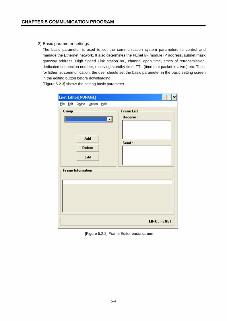
CHAPTER 5 COMMUNICATION PROGRAM
5-4
2) Basic parameter settings The basic parameter is used to set the communication system parameters to control and manage the Ethernet network. It also determines the FEnet I/F module IP address, subnet mask, gateway address, High Speed Link station no., channel open time, times of retransmission, dedicated connection number, receiving standby time, TTL (time that packet is alive.) etc. Thus, for Ethernet communication, the user should set the basic parameter in the basic setting screen in the editing button before downloading. [Figure 5.2.3] shows the setting basic parameter.
[Figure 5.2.2] Frame Editor basic screen
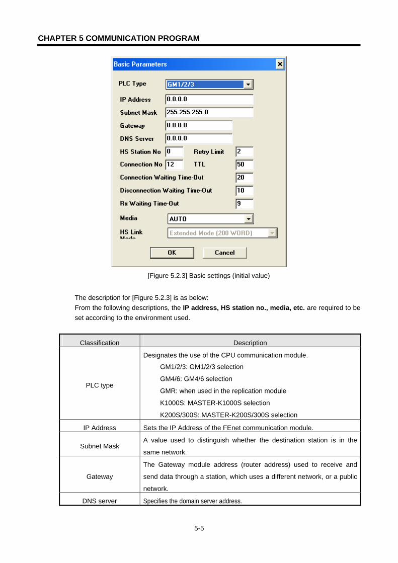
CHAPTER 5 COMMUNICATION PROGRAM
5-5
[Figure 5.2.3] Basic settings (initial value)
The description for [Figure 5.2.3] is as below: From the following descriptions, the IP address, HS station no., media, etc. are required to be set according to the environment used.
Classification Description
PLC type
Designates the use of the CPU communication module.
▷ GM1/2/3: GM1/2/3 selection
▷ GM4/6: GM4/6 selection
▷ GMR: when used in the replication module
▷ K1000S: MASTER-K1000S selection
▷ K200S/300S: MASTER-K200S/300S selection
IP Address Sets the IP Address of the FEnet communication module.
Subnet Mask A value used to distinguish whether the destination station is in the
same network.
Gateway
The Gateway module address (router address) used to receive and
send data through a station, which uses a different network, or a public
network.
DNS server Specifies the domain server address.
CHAPTER 5 COMMUNICATION PROGRAM
5-6
Classification Description
HS station No Sets the station number when communicating between the GLOFA PLC FEnet module and the High Speed Link.
Retry Limit Count of re-transmission if there is no reply from the destination station.
Connection Waiting
Time-Out
Time to wait to connect with the destination station, XXX_TCPACT, XXX_TCPPAS are set in E_CONN Function Block. An error occurs when it is impossible to connect in the set time.
Disconnection Waiting
Time-Out
Time to wait for the reply of the destination station when asking for a release of the connection. If there is no reply after a fixed amount of time the connection ends.
RX Waiting Time-Out
During dedicated communication, if there is no requirement from the
high level for a fixed time with a high level PC or HMI connected, it ends
the dedicated service connection on the assumption that there is a
problem in the system. In other words, this latency time is used in the
dedicated service to set a new channel again in the case that a problem
occurs in the destination station, or a cable is disconnected.
TTL If the destination station does not belong to the network, it searches the destination station via a router within a range of the maximum set value of TTL..
Connection No Maximum number of dedicated TCP service to be connected at the same time. (1 up to16)
Media
Select the media desired to use.
AUTO: recognize the currently installed module and control it
automatically.
10M/FULL: 10MBps Full Duplex electric
100M/FULL: 100MBps Full Duplex electric
FX/100M/FULL: 100MBps Full Duplex light (10BASE5/2 or 10BASE-
T)
HS Link Mode
Applied when PLC type is GM4/6. designates the High Speed Link
sending/receiving data number according to CPU type.
▷ Extended mode (200 WORD): extends max. sending/receiving
data size per block up to 200words (GM4C).
▷ Basic mode (60 WORD) GM4/6: limits max. sending/receiving
data size per block as 60words (GM4A/B).

CHAPTER 5 COMMUNICATION PROGRAM
5-7
5.2.3 Connecting and Downloading using the communication module
1) Downloading/Uploading the Frame
You can download (write) defined basic parameters and frames in the Ethernet communication module with Frame Editor. Uploading (reading) the frame or the parameter from the Ethernet communication module is also available.
(1) Write (download)
When CPU is running, stop the CPU before doing ‘write’. If you carry out ‘write’ while running, it may affect the communication seriously.
a) For connection, use the CPU of main base that Ethernet communication module
desired to write frame and parameter is installed or ‘connect; by online.
[Figure 5.2.5] shows the completion of connection. (In case of using COM port
such as GMWIN/KGLWIN, disconnect GMWIN/KGLWIN before connecting.)
[Figure 5.2.4] ‘Connect’ screen

CHAPTER 5 COMMUNICATION PROGRAM
5-8
[Figure 5.2.5] ‘Connection completion’ screen
b) After connection is completed, if you select ‘write’ by online, [Figure 5.2.6] screen
appears. From this screen, designate slot position, frame and parameter that
Ethernet communication module desired to write (download) is installed.
[Figure 5.2.6] ‘Write’ screen
Classification Description
Slot No. Shows slot no. that communication module of dedicated
communication is installed. (0 ~ 55 setting available)
Basic
parameters
Downloads only the contents set in the basic parameter.
(IP address, HS station no. etc)
Frames Downloads ‘user definition’ frame.
(frame list)
Communicatio
n option
All Downloads the basic parameter and user definition frame at the
same time.

CHAPTER 5 COMMUNICATION PROGRAM
5-9
c) If you select ‘write’ from b), please verify once again before writing the data.
[Figure 5.2.7] ‘Write’ verification screen
d) If all procedure on the above are finished, this means that frame file write is
finished normally but the parameter value that FEnet I/F module is active
currently is the value downloaded previously. Thus, after downloading, apply the
power again or reset before using. Otherwise, it continues to run with the
past value.
2) Read (Upload) a) Connects the CPU of main base that F I/F module desired to read is installed.
b) After connecting, if you select ‘read’ by online, [Figure 5.2.8] screen appears.
After selecting the slot no. and communication option, select ‘read’ button.
[Figure 5.2.8] ‘Read’ screen
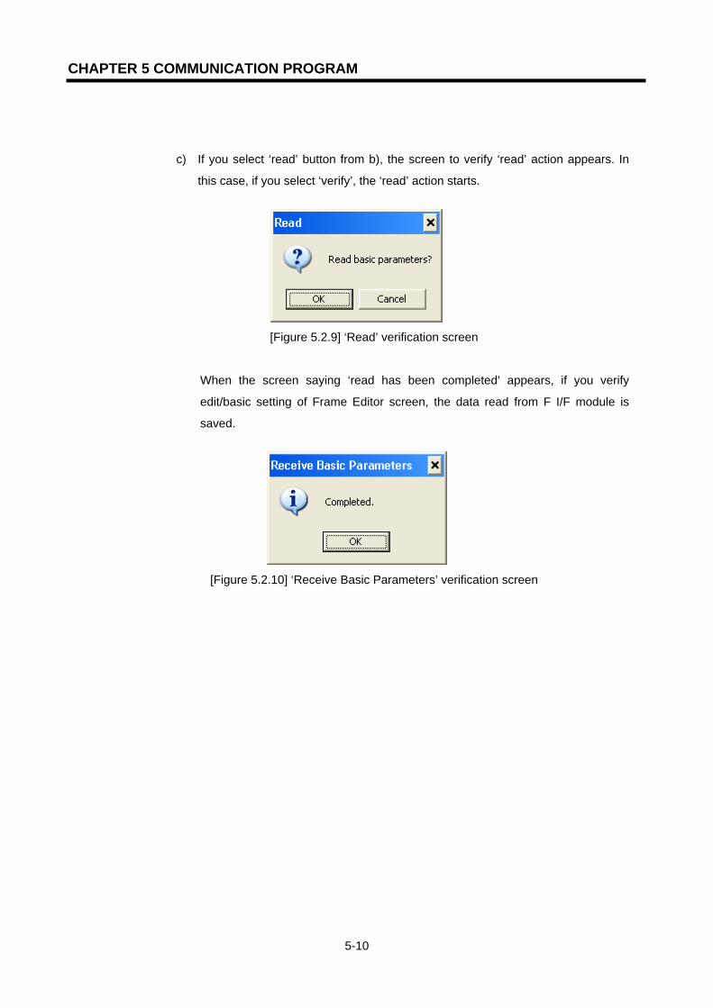
CHAPTER 5 COMMUNICATION PROGRAM
5-10
c) If you select ‘read’ button from b), the screen to verify ‘read’ action appears. In
this case, if you select ‘verify’, the ‘read’ action starts.
[Figure 5.2.9] ‘Read’ verification screen
When the screen saying ‘read has been completed’ appears, if you verify
edit/basic setting of Frame Editor screen, the data read from F I/F module is
saved.
[Figure 5.2.10] ‘Receive Basic Parameters’ verification screen

CHAPTER 6 HIGH SPEED LINK
6-1
CHAPTER 6 HIGH SPEED LINK
6.1 Introduction
The High Speed Link is a type of communication system between GLOFA / MASTER PLC
communication modules. It can send and receive data by setting up High Speed Link parameters.
It is also a data transmission service in which a user can exchange data by setting up the data
volume, period, area, and save area of the TX/RX parameters. However, the High Speed Link
service can have an influence on other communication modules using the same module because it
uses a subnet broad service. Therefore, if a user wants little influence on other modules and an
efficient maximization of communication, the user should set up data using nearly all the maximum
settable numbers (400 bytes) of the TX/RX per High Speed Link block. In this way, the total block
numbers used is reduced. To use all of the functions, the user must download by setting the basic
parameters. (See section 6.2 Setup of Parameter)
High Speed Link function is as follows.
- High Speed Link Block Setting: A user can set 64 blocks, 32 for TX and 32 for RX, if
there are several RX/TX areas. Up to 200 words per block can be set. Thus,
the maximum link dot number is 12,800 words.
- TX/RX Period Setting: The TX/RX period can be set by a user for each block. The user can
also set the TX/RX period from 200 to 10 sec for the areas where especially
fast RX/TX is required. Therefore, the user can increase the total communication
efficiency.
- TX/RX Area Setting: A user can set the TX/RX area for each data block according to the
I/O MAP.
- High Speed Link Information: Since it offers a user High Speed Link information by the
user keywords of GMWIN, it is easy to build reliable communications.
Table 6.1 shows the High Speed Link dot numbers per communication device type.
In Table 6.1, the unit of basic link length is 1 word.
Classification Maximum
communication bit numbers
Maximum transmitting bit
numbers
Maximum block numbers
Maximum bit numbers per
block GM3/K1000S 12,800 6,400 64 (0-63) 200
GM4/6, K300S/200S 3,840 3,200 64 (0-63) 60 [Table 6.1] Maximum communication length per device type
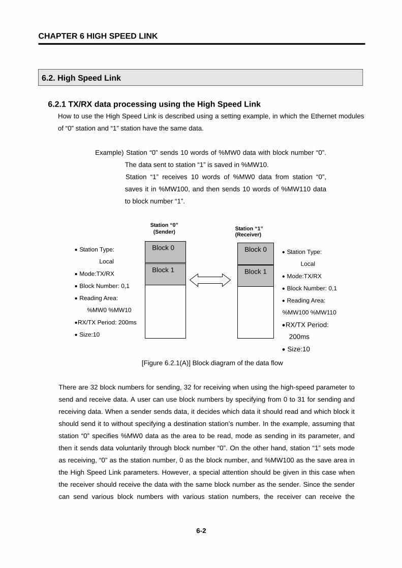
CHAPTER 6 HIGH SPEED LINK
6-2
6.2. High Speed Link
6.2.1 TX/RX data processing using the High Speed Link How to use the High Speed Link is described using a setting example, in which the Ethernet modules
of “0” station and “1” station have the same data.
Example) Station “0” sends 10 words of %MW0 data with block number “0”.
The data sent to station “1” is saved in %MW10.
Station “1” receives 10 words of %MW0 data from station “0”,
saves it in %MW100, and then sends 10 words of %MW110 data
to block number “1”.
[Figure 6.2.1(A)] Block diagram of the data flow
There are 32 block numbers for sending, 32 for receiving when using the high-speed parameter to
send and receive data. A user can use block numbers by specifying from 0 to 31 for sending and
receiving data. When a sender sends data, it decides which data it should read and which block it
should send it to without specifying a destination station’s number. In the example, assuming that
station “0” specifies %MW0 data as the area to be read, mode as sending in its parameter, and
then it sends data voluntarily through block number “0”. On the other hand, station “1” sets mode
as receiving, “0” as the station number, 0 as the block number, and %MW100 as the save area in
the High Speed Link parameters. However, a special attention should be given in this case when
the receiver should receive the data with the same block number as the sender. Since the sender
can send various block numbers with various station numbers, the receiver can receive the
Station “0” (Sender)
• Station Type:
Local
• Mode:TX/RX
• Block Number: 0,1
• Reading Area:
%MW0 %MW10
•RX/TX Period: 200ms
• Size:10
Block 0
Block 1
Block 0
Station “1”(Receiver)
• Station Type:
Local
• Mode:TX/RX
• Block Number: 0,1
• Reading Area:
%MW100 %MW110
•RX/TX Period:
200ms
• Size:10
Block 1

CHAPTER 6 HIGH SPEED LINK
6-3
required data only after it confirms which data is sent in which block, and then sends the data
through the appropriate block number. In contrast, station “1” should only set the data to be sent
corresponding to the sending setup of station “0”, and station “0” should only set the receiving
setup corresponding to that of station “1”.
Sending setup for station “0”
Receiving setup for station “0”

CHAPTER 6 HIGH SPEED LINK
6-4
Setup of sending and receiving for station “0”

CHAPTER 6 HIGH SPEED LINK
6-5
Receiving setup for station “1”
Sending setup for station “1”

CHAPTER 6 HIGH SPEED LINK
6-6
Sending and receiving setup for station “1”
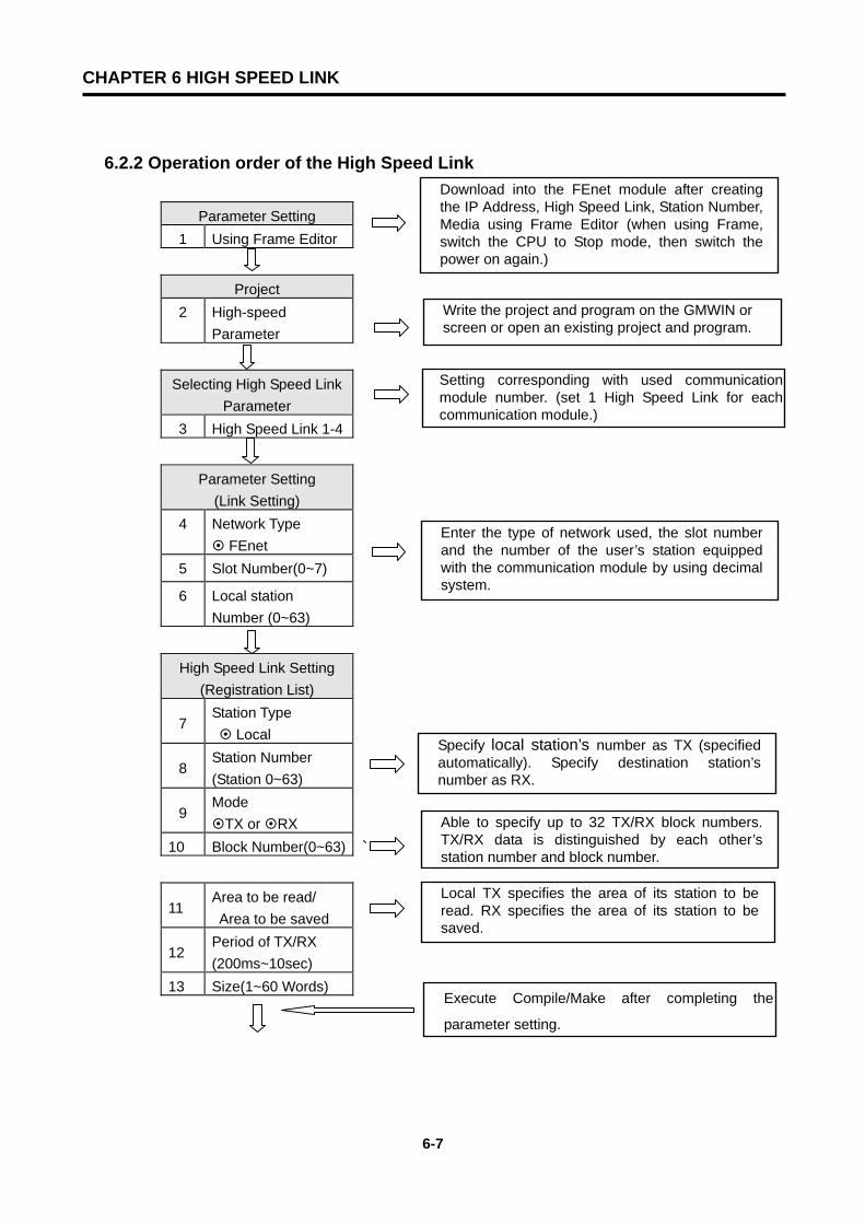
CHAPTER 6 HIGH SPEED LINK
6-7
6.2.2 Operation order of the High Speed Link
Parameter Setting 1 Using Frame Editor
Project 2 High-speed
Parameter
Selecting High Speed Link Parameter
3 High Speed Link 1-4
Parameter Setting (Link Setting)
4 Network Type FEnet
5 Slot Number(0~7)
6 Local station Number (0~63)
High Speed Link Setting (Registration List)
7 Station Type Local
8 Station Number (Station 0~63)
9 Mode
TX or RX 10 Block Number(0~63)
11 Area to be read/ Area to be saved
12 Period of TX/RX (200ms~10sec)
13 Size(1~60 Words)
Download into the FEnet module after creating the IP Address, High Speed Link, Station Number, Media using Frame Editor (when using Frame, switch the CPU to Stop mode, then switch the power on again.)
Write the project and program on the GMWIN or screen or open an existing project and program.
Setting corresponding with used communicationmodule number. (set 1 High Speed Link for eachcommunication module.)
Enter the type of network used, the slot number and the number of the user’s station equipped with the communication module by using decimal system.
Specify local station’s number as TX (specified automatically). Specify destination station’s number as RX.
Able to specify up to 32 TX/RX block numbers. TX/RX data is distinguished by each other’s station number and block number.
Local TX specifies the area of its station to be read. RX specifies the area of its station to be saved.
Execute Compile/Make after completing the
parameter setting.

CHAPTER 6 HIGH SPEED LINK
6-8
On-line (after local connection)
14
Writing High Speed Link Parameter
Parameter and Program
Link Enable Setting 15 High Speed Link
1~4
16 Operate mode RUN
Against communication 1~16
Download the High Speed Link parameter and program of the GMWIN into the CPU.
Set the appropriate Link Enable for high-speed link operation. When downloading the program and parameters, it is required to set the Link Enable again because the existing Link Enable is off.
※ Please write a program using an emergency flag
against communication interruption, destination
station’s error, or/and a momentary power failure
of the remote module at time of communication.

CHAPTER 6 HIGH SPEED LINK
6-9
6.2.3 Setting the High Speed Link Parameter The High Speed Link parameter sets the appropriate items by selecting the link parameter on the
GMWIN project screen. The setting order and the function of each item are as follows:
1) Setting the GMWIN project
The High Speed Link parameter is selected on the basic project screen [Figure 6.2.3(A)].
The basic screen of the link parameter appears [Figure 6.2.3(B)], and then the appropriate items
can be selected here.
[Figure 6.2.3(A)] Basic screen of the GMWIN project

CHAPTER 6 HIGH SPEED LINK
6-10
2) Selecting the link parameter
A) Setting method
Go into ‘High Speed Link Parameter’ by selecting the appropriate parameter on the basic
screen [Figure 6.2.3(B)].
[Figure 6.2.3(B)] The Basic Screen of the High Speed Link Parameter
B) Setting function
The High Speed Link items of [Figure 6.2.3(B)] mean that the maximum communication
modules are equipped according to the CPU type of the PLC. For example, the GLOFA-
GMR/GM1/GM2/GM3 CPU can have a maximum of 4 communication modules, and it can set
High Speed Link from 1 to 4. However, the GLOFA-GM4 CPU can only have a maximum of 2
communication modules. The High Speed Link 1 and 2 buttons are marked with a dark deep
color, and the rest is impossible to set. At this time, the High Speed Link number has nothing
to do with the mounted slot number. A user should set the slot number on ‘Setup’ for each
parameter, and only one High Speed Link parameter should be set for each communication
module. [Table 6.2.3(A)] displays the communication device to be mounted and the maximum
number of module for each CPU of GLOFA .
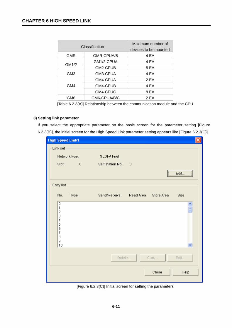
CHAPTER 6 HIGH SPEED LINK
6-11
Classification Maximum number of
devices to be mounted GMR GMR-CPUA/B 4 EA
GM1/2-CPUA 4 EA GM1/2
GM2-CPUB 8 EA GM3 GM3-CPUA 4 EA
GM4-CPUA 2 EA GM4-CPUB 4 EA GM4 GM4-CPUC 8 EA
GM6 GM6-CPUA/B/C 2 EA [Table 6.2.3(A)] Relationship between the communication module and the CPU
3) Setting link parameter
If you select the appropriate parameter on the basic screen for the parameter setting [Figure
6.2.3(B)], the initial screen for the High Speed Link parameter setting appears like [Figure 6.2.3(C)].
[Figure 6.2.3(C)] Initial screen for setting the parameters
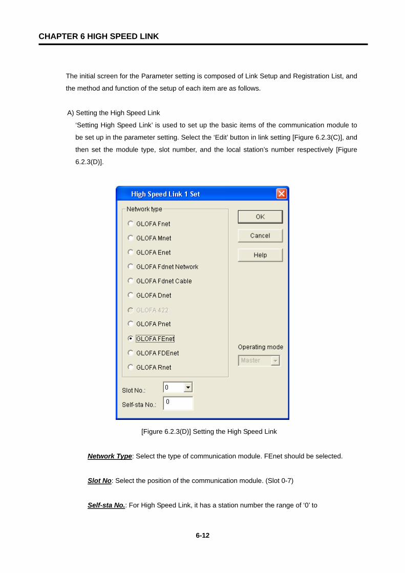
CHAPTER 6 HIGH SPEED LINK
6-12
The initial screen for the Parameter setting is composed of Link Setup and Registration List, and
the method and function of the setup of each item are as follows.
A) Setting the High Speed Link
‘Setting High Speed Link’ is used to set up the basic items of the communication module to
be set up in the parameter setting. Select the ‘Edit’ button in link setting [Figure 6.2.3(C)], and
then set the module type, slot number, and the local station’s number respectively [Figure
6.2.3(D)].
[Figure 6.2.3(D)] Setting the High Speed Link
Network Type: Select the type of communication module. FEnet should be selected.
Slot No: Select the position of the communication module. (Slot 0-7)
Self-sta No.: For High Speed Link, it has a station number the range of ‘0’ to
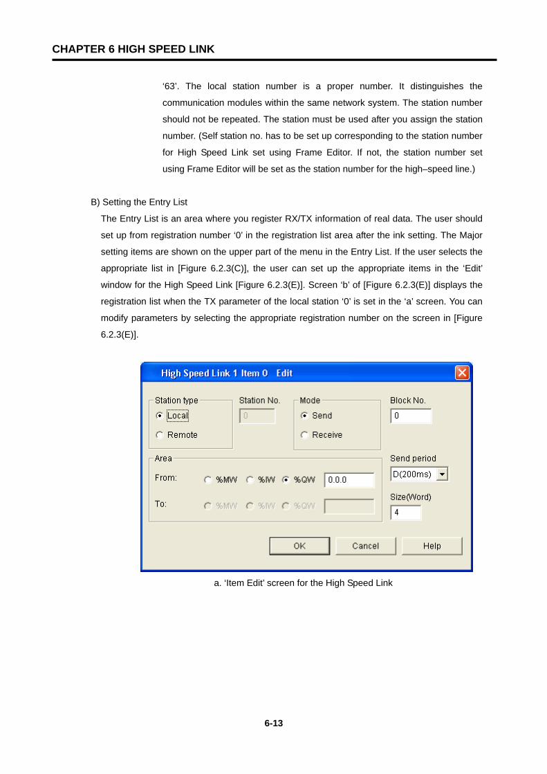
CHAPTER 6 HIGH SPEED LINK
6-13
‘63’. The local station number is a proper number. It distinguishes the
communication modules within the same network system. The station number
should not be repeated. The station must be used after you assign the station
number. (Self station no. has to be set up corresponding to the station number
for High Speed Link set using Frame Editor. If not, the station number set
using Frame Editor will be set as the station number for the high–speed line.)
B) Setting the Entry List
The Entry List is an area where you register RX/TX information of real data. The user should
set up from registration number ‘0’ in the registration list area after the ink setting. The Major
setting items are shown on the upper part of the menu in the Entry List. If the user selects the
appropriate list in [Figure 6.2.3(C)], the user can set up the appropriate items in the ‘Edit’
window for the High Speed Link [Figure 6.2.3(E)]. Screen ‘b’ of [Figure 6.2.3(E)] displays the
registration list when the TX parameter of the local station ‘0’ is set in the ‘a’ screen. You can
modify parameters by selecting the appropriate registration number on the screen in [Figure
6.2.3(E)].
a. ‘Item Edit’ screen for the High Speed Link
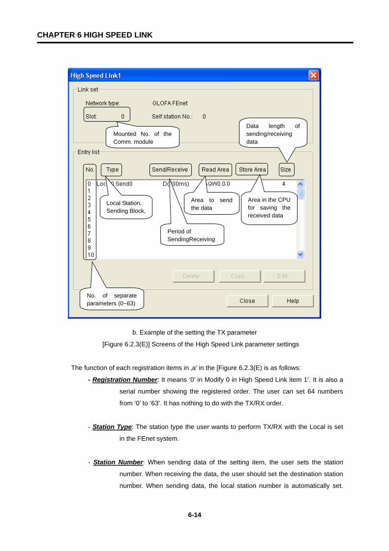
CHAPTER 6 HIGH SPEED LINK
6-14
b. Example of the setting the TX parameter
[Figure 6.2.3(E)] Screens of the High Speed Link parameter settings
The function of each registration items in ‚a’ in the [Figure 6.2.3(E) is as follows:
- Registration Number: It means ‘0’ in Modify 0 in High Speed Link item 1’. It is also a
serial number showing the registered order. The user can set 64 numbers
from ‘0’ to ‘63’. It has nothing to do with the TX/RX order.
- Station Type: The station type the user wants to perform TX/RX with the Local is set
in the FEnet system.
- Station Number: When sending data of the setting item, the user sets the station
number. When receiving the data, the user should set the destination station
number. When sending data, the local station number is automatically set.
Mounted No. of theComm. module
No. of separateparameters (0~63)
Local Station, Sending Block,
Period of SendingReceiving
Area to sendthe data
Area in the CPUfor saving thereceived data
Data length ofsending/receiving data
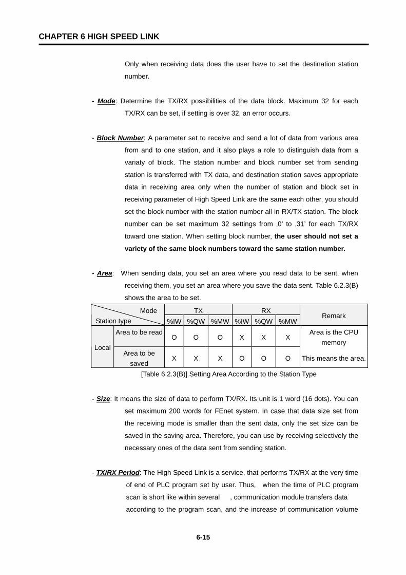
CHAPTER 6 HIGH SPEED LINK
6-15
Only when receiving data does the user have to set the destination station
number.
- Mode: Determine the TX/RX possibilities of the data block. Maximum 32 for each
TX/RX can be set, if setting is over 32, an error occurs.
- Block Number: A parameter set to receive and send a lot of data from various area
from and to one station, and it also plays a role to distinguish data from a
variaty of block. The station number and block number set from sending
station is transferred with TX data, and destination station saves appropriate
data in receiving area only when the number of station and block set in
receiving parameter of High Speed Link are the same each other, you should
set the block number with the station number all in RX/TX station. The block
number can be set maximum 32 settings from ‚0’ to ‚31’ for each TX/RX
toward one station. When setting block number, the user should not set a
variety of the same block numbers toward the same station number.
- Area: When sending data, you set an area where you read data to be sent. when
receiving them, you set an area where you save the data sent. Table 6.2.3(B)
shows the area to be set.
TX RX Mode Station type %IW %QW %MW %IW %QW %MW
Remark
Area to be read O O O X X X
Area is the CPU memory
Local Area to be
saved X X X O O O This means the area.
[Table 6.2.3(B)] Setting Area According to the Station Type
- Size: It means the size of data to perform TX/RX. Its unit is 1 word (16 dots). You can
set maximum 200 words for FEnet system. In case that data size set from
the receiving mode is smaller than the sent data, only the set size can be
saved in the saving area. Therefore, you can use by receiving selectively the
necessary ones of the data sent from sending station.
- TX/RX Period: The High Speed Link is a service, that performs TX/RX at the very time
of end of PLC program set by user. Thus, when the time of PLC program
scan is short like within several , communication module transfers data
according to the program scan, and the increase of communication volume
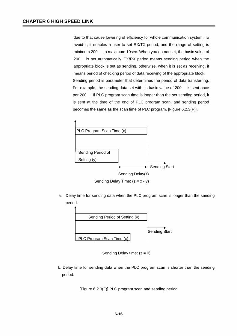
CHAPTER 6 HIGH SPEED LINK
6-16
due to that cause lowering of efficiency for whole communication system. To
avoid it, it enables a user to set RX/TX period, and the range of setting is
minimum 200 to maximum 10sec. When you do not set, the basic value of
200 is set automatically. TX/RX period means sending period when the
appropriate block is set as sending, otherwise, when it is set as receiving, it
means period of checking period of data receiving of the appropriate block.
Sending period is parameter that determines the period of data transferring.
For example, the sending data set with its basic value of 200 is sent once
per 200. If PLC program scan time is longer than the set sending period, it
is sent at the time of the end of PLC program scan, and sending period
becomes the same as the scan time of PLC program. [Figure 6.2.3(F)].
PLC Program Scan Time (x)
Sending Period of
Setting (y)
Sending Start
Sending Delay(z)
Sending Delay Time: (z = x - y)
a. Delay time for sending data when the PLC program scan is longer than the sending
period.
Sending Period of Setting (y)
Sending Start
PLC Program Scan Time (x)
Sending Delay time: (z = 0)
b. Delay time for sending data when the PLC program scan is shorter than the sending
period.
[Figure 6.2.3(F)] PLC program scan and sending period

CHAPTER 6 HIGH SPEED LINK
6-17
In case of data sending, when the appropriate block data is received on the
set time, the appropriate TRX_MODE flag of link information should be on,
and if not, it should be off, then, it makes run-link and link trouble contact.
Therefore, you can check whether data are sent normally even after you set
above the sending period of the appropriate block set from destination station.
TX/RX time becomes different from the total amount of number of block for
High Speed Link setting and volume of TX/RX data per block and the total
amount of communications such as communication stations of network, let
alone the time of PLC program scan. Therefore, if you set TX/RX period,
you should set them referring to calculating the speed of the High Speed Link
in Chapter 6.2.6.
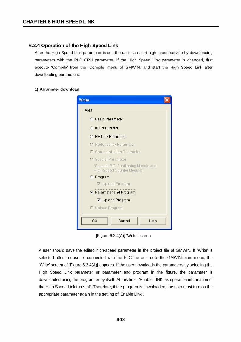
CHAPTER 6 HIGH SPEED LINK
6-18
6.2.4 Operation of the High Speed Link After the High Speed Link parameter is set, the user can start high-speed service by downloading
parameters with the PLC CPU parameter. If the High Speed Link parameter is changed, first
execute ‘Compile’ from the ‘Compile’ menu of GMWIN, and start the High Speed Link after
downloading parameters.
1) Parameter download
[Figure 6.2.4(A)] ‘Write’ screen
A user should save the edited high-speed parameter in the project file of GMWIN. If ‘Write’ is
selected after the user is connected with the PLC the on-line to the GMWIN main menu, the
‘Write’ screen of [Figure 6.2.4(A)] appears. If the user downloads the parameters by selecting the
High Speed Link parameter or parameter and program in the figure, the parameter is
downloaded using the program or by itself. At this time, ‘Enable LINK’ as operation information of
the High Speed Link turns off. Therefore, if the program is downloaded, the user must turn on the
appropriate parameter again in the setting of ‘Enable Link’.
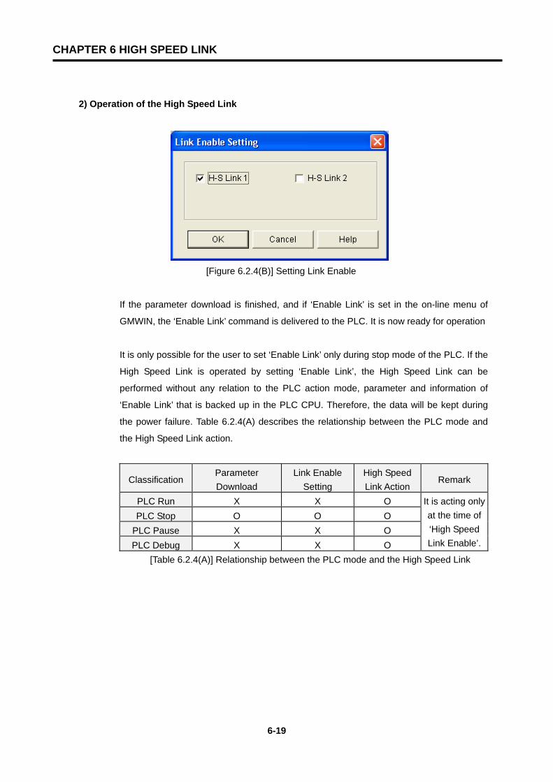
CHAPTER 6 HIGH SPEED LINK
6-19
2) Operation of the High Speed Link
[Figure 6.2.4(B)] Setting Link Enable
If the parameter download is finished, and if ‘Enable Link’ is set in the on-line menu of
GMWIN, the ‘Enable Link’ command is delivered to the PLC. It is now ready for operation
It is only possible for the user to set ‘Enable Link’ only during stop mode of the PLC. If the
High Speed Link is operated by setting ‘Enable Link’, the High Speed Link can be
performed without any relation to the PLC action mode, parameter and information of
‘Enable Link’ that is backed up in the PLC CPU. Therefore, the data will be kept during
the power failure. Table 6.2.4(A) describes the relationship between the PLC mode and
the High Speed Link action.
Classification Parameter Download
Link Enable Setting
High Speed Link Action
Remark
PLC Run X X O PLC Stop O O O
PLC Pause X X O PLC Debug X X O
It is acting only at the time of ‘High Speed Link Enable’.
[Table 6.2.4(A)] Relationship between the PLC mode and the High Speed Link
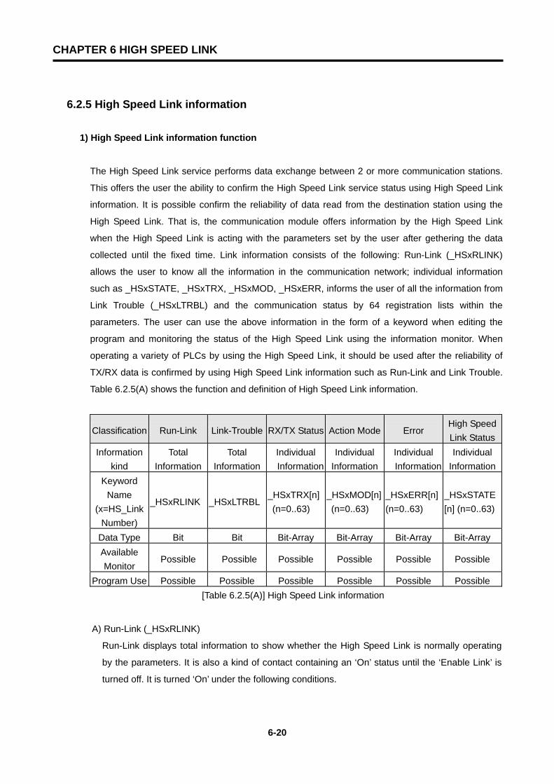
CHAPTER 6 HIGH SPEED LINK
6-20
6.2.5 High Speed Link information
1) High Speed Link information function
The High Speed Link service performs data exchange between 2 or more communication stations.
This offers the user the ability to confirm the High Speed Link service status using High Speed Link
information. It is possible confirm the reliability of data read from the destination station using the
High Speed Link. That is, the communication module offers information by the High Speed Link
when the High Speed Link is acting with the parameters set by the user after gethering the data
collected until the fixed time. Link information consists of the following: Run-Link (_HSxRLINK)
allows the user to know all the information in the communication network; individual information
such as _HSxSTATE, _HSxTRX, _HSxMOD, _HSxERR, informs the user of all the information from
Link Trouble (_HSxLTRBL) and the communication status by 64 registration lists within the
parameters. The user can use the above information in the form of a keyword when editing the
program and monitoring the status of the High Speed Link using the information monitor. When
operating a variety of PLCs by using the High Speed Link, it should be used after the reliability of
TX/RX data is confirmed by using High Speed Link information such as Run-Link and Link Trouble.
Table 6.2.5(A) shows the function and definition of High Speed Link information.
Classification Run-Link Link-Trouble RX/TX Status Action Mode Error High Speed Link Status
Information kind
Total Information
Total Information
Individual Information
Individual Information
Individual Information
Individual Information
Keyword Name
(x=HS_Link Number)
_HSxRLINK _HSxLTRBL _HSxTRX[n] (n=0..63)
_HSxMOD[n] (n=0..63)
_HSxERR[n] (n=0..63)
_HSxSTATE[n] (n=0..63)
Data Type Bit Bit Bit-Array Bit-Array Bit-Array Bit-Array Available Monitor
Possible Possible Possible Possible Possible Possible
Program Use Possible Possible Possible Possible Possible Possible [Table 6.2.5(A)] High Speed Link information
A) Run-Link (_HSxRLINK)
Run-Link displays total information to show whether the High Speed Link is normally operating
by the parameters. It is also a kind of contact containing an ‘On’ status until the ‘Enable Link’ is
turned off. It is turned ‘On’ under the following conditions.
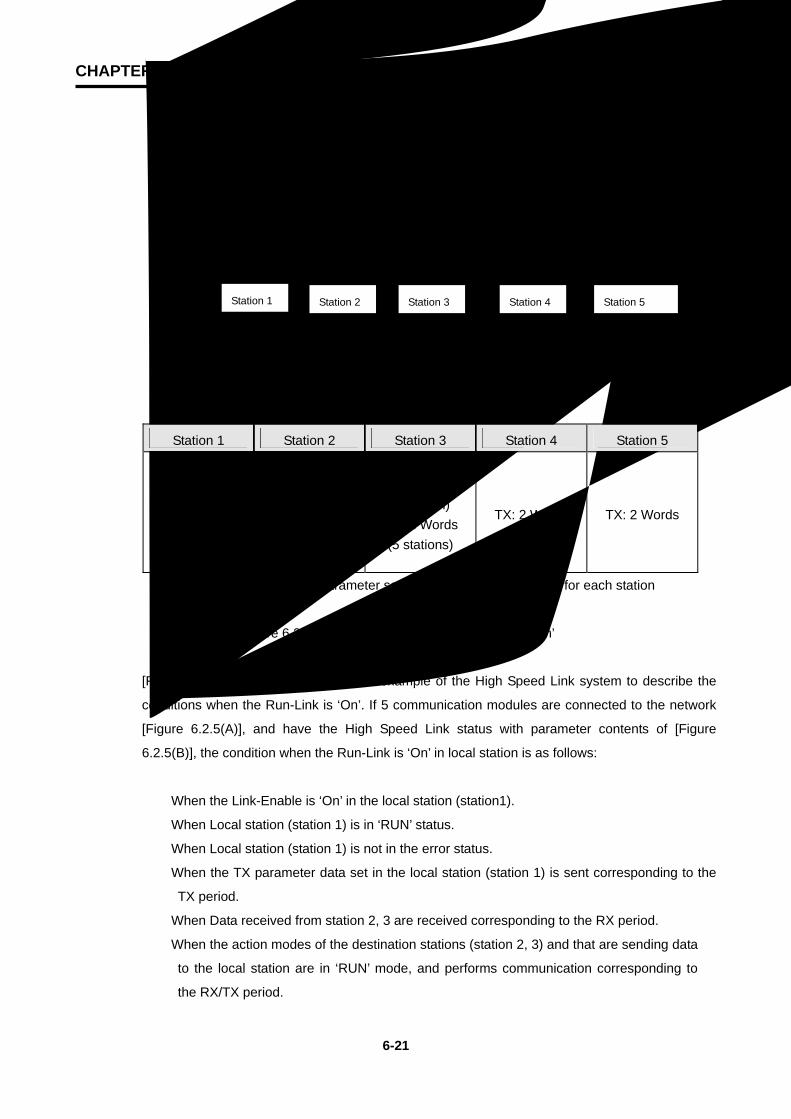
CHAPTER 6 HIGH SPEED LINK
6-21
① When ‘Enable Link’ is ‘On’.
② When the registration list setting of the parameters is normally set.
③ When all the data in the registration list of the parameters is sent and received
corresponding to the service period.
④ When the status of all the destination stations set in parameter is in ‘RUN’ and there are no
errors.
1 Station 2 Station 3 Station 4 Station 5 Station
(a) Configuration of the High Speed Link System
(b) Example of the parameter setting of the High Speed Link for each station
[Figure 6.2.5(A)] Conditions when the Run-Link is ‘On’
[Figure 6.2.5(A)] shows a configuration example of the High Speed Link system to describe the
conditions when the Run-Link is ‘On’. If 5 communication modules are connected to the network
[Figure 6.2.5(A)], and have the High Speed Link status with parameter contents of [Figure
6.2.5(B)], the condition when the Run-Link is ‘On’ in local station is as follows:
① When the Link-Enable is ‘On’ in the local station (station1).
② When Local station (station 1) is in ‘RUN’ status.
③ When Local station (station 1) is not in the error status.
④ When the TX parameter data set in the local station (station 1) is sent corresponding to the
TX period.
⑤ When Data received from station 2, 3 are received corresponding to the RX period.
⑥ When the action modes of the destination stations (station 2, 3) and that are sending data
to the local station are in ‘RUN’ mode, and performs communication corresponding to
the RX/TX period.
Station 1 Station 2 Station 3 Station 4 Station 5
TX: 2 Words RX: 2 Words (2 stations)
RX: 2 Words (3 Stations)
TX: 2 Words RX: 2 Words
(1 station) RX: 2 Words (4 stations)
TX: 2 Words RX: 2 Words
(1 station) RX: 2 Words (5 stations)
TX: 2 Words TX: 2 Words
Station 5 Station 2 Station 1 Station 3 Station 4
CHAPTER 6 HIGH SPEED LINK
6-22
⑦ When the other destination stations’ (station 4, 5) action modes are set in the destination
station’s parameter (station 2, 3) of the local station (station 1) are in ‘RUN’ mode, and are
not in error status, and performs communication corresponding to the RX/TX period.
If all the conditions meet the qualifications, the RUN-Link of the local station is ‘On’. If the RUN-
Link is operating with PLCs of several stations that connected with each other through the High
Speed Link, the user can conduct the mutual monitoring of the data sent and received with
reliable communication. But, once the ‘RUN-Link’ contact is ‘On’ remains ‘On’ until the Link-
Enable is ‘Off’. Therefore, if the user monitors an abnormal status such as communication error,
the user should use the following Information Contact of Link Trouble.
B) Link-Trouble (_HSxLTRBL x=High Speed Link Number (1~4))
It displays total information indicating if High Speed Link is normally operating by the parameter
set by the user. It turns ‘On’ when the Run-Link is off, and it turns ‘Off’ when the Run-Link is on.
C) RX/TX Status (_HSxTRX[0..63] x=High speed Link Number (1~4))
Individual information showing the action status by the registration list of the High Speed Link
parameter, and also showing a maximum 64 of RX/TX information by the registration list. If
RX/TX action towards the registration item is done corresponding to the RX/TX period, the
appropriate ‘Bit’ turns ‘On’. If not, it turns ‘Off’.
D) Operating Mode (_HSxMODE[0..63] x=High Speed Link Number (1~4))
Individual information showing the action status by the registration list of the High Speed Link
parameter. It shows maximum 64 action modes information by registration list as maximum
registration numbers. If the station set in the registration item is in ‘Run’ mode, the appropriate
‘Bit’ turns ‘On’. If it is in Stop/Pause/Debug mode, it turns ‘Off’.
E) Error (_HSxERR[0..63] x=High Speed Link Number (1~4))
Individual information showing the action status by the registration list of the High Speed Link
parameter, and also showing maximum 64 error information by registration list as maximum
registration number. The ‘Error’ displays the status overall, in which the PLC does not perform
the user program normally. ‘Off’ means that the destination station’s PLC is acting normally. ‘On’
means that the destination station is acting abnormally
F) High Speed Link Status (_HSxSTATE[0..63] x=High Speed Link Number (1~4))
Individual information showing the action status by the registration list of the High Speed Link
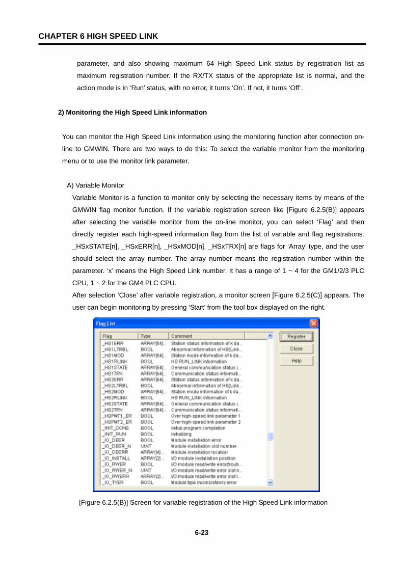
CHAPTER 6 HIGH SPEED LINK
6-23
parameter, and also showing maximum 64 High Speed Link status by registration list as
maximum registration number. If the RX/TX status of the appropriate list is normal, and the
action mode is in ‘Run’ status, with no error, it turns ‘On’. If not, it turns ‘Off’.
2) Monitoring the High Speed Link information
You can monitor the High Speed Link information using the monitoring function after connection on-
line to GMWIN. There are two ways to do this: To select the variable monitor from the monitoring
menu or to use the monitor link parameter.
A) Variable Monitor
Variable Monitor is a function to monitor only by selecting the necessary items by means of the
GMWIN flag monitor function. If the variable registration screen like [Figure 6.2.5(B)] appears
after selecting the variable monitor from the on-line monitor, you can select ‘Flag’ and then
directly register each high-speed information flag from the list of variable and flag registrations.
_HSxSTATE[n], _HSxERR[n], _HSxMOD[n], _HSxTRX[n] are flags for ‘Array’ type, and the user
should select the array number. The array number means the registration number within the
parameter. ‘x’ means the High Speed Link number. It has a range of 1 ~ 4 for the GM1/2/3 PLC
CPU, 1 ~ 2 for the GM4 PLC CPU.
After selection ‘Close’ after variable registration, a monitor screen [Figure 6.2.5(C)] appears. The
user can begin monitoring by pressing ‘Start’ from the tool box displayed on the right.
[Figure 6.2.5(B)] Screen for variable registration of the High Speed Link information

CHAPTER 6 HIGH SPEED LINK
6-24
[Figure 6.2.5(C)] shows the monitoring results by monitoring the first parameter of the High Speed
Link 1.
[Figure 6.2.5(C)] Monitoring screen for the High Speed Link information (variable registration)
B) Monitoring link parameter
If the link parameter item is selected from the monitoring menu of the on-line connection of
GMWIN, a screen for selecting the link parameter [Figure 6.2.5(D)] appears. If the user clicks
‘OK’ after selecting the parameters, a screen for monitoring the high-speed parameters [Figure
6.2.5(E)] is open. The set registration list is shown when it is monitored.
[Figure 6.2.5(D)] Screen for selecting the Link Parameter
For link parameter monitoring, the total information of RUN-Link, and Link Trouble is displayed at
the top of the screen in [Figure 6.2.5(E)]. Mode (operating mode), communication (RX/TX status),
individual information of error are displayed with registration numbers as many as set numbers.
[Figure 6.2.5(E)] shows the monitoring screen when 2 of High Speed Link parameters are set for
High Speed Link parameter 1 .
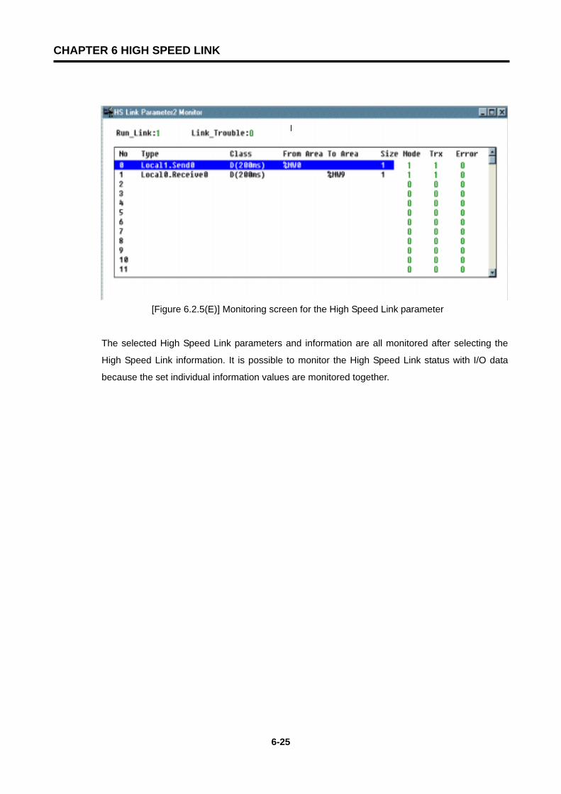
CHAPTER 6 HIGH SPEED LINK
6-25
[Figure 6.2.5(E)] Monitoring screen for the High Speed Link parameter
The selected High Speed Link parameters and information are all monitored after selecting the
High Speed Link information. It is possible to monitor the High Speed Link status with I/O data
because the set individual information values are monitored together.

CHAPTER 6 HIGH SPEED LINK
6-26
6.2.6 Calculating the speed of the High Speed Link
1) Introduction
The transfer rate of High Speed Link data can be fixed according to various factors. This is
because the data of a block goes through the same path as [Figure 6.2.6(A)] until it is saved in the
RX area of another station after being sent from a station.
PLC - CPU(A) PLC - CPU(B)
Communication Module (Station 1) Communication Module (Station 2)
Data Sending Data Receiving
[Figure 6.2.6(A)] Data transfer path by the communication module
Sending data to other stations using communication similar to [Figure 6.2.6(A)], must go through 3
paths. The time spent on each path is crucial for the sending time.
Table 6.2.6(A) shows the major path of data transfer and the crucial factors influencing the time of
each path.
Item Path Factor influencing on time
1 PLC CPU(A) Communication Module
(Station 1) Program Scan Time of PLC-A
2 Communication Module (Station 1) Communication Module (Station 2)
Communication Scan Time+Communication O/S Scan Time
3 Communication Module (Station 2)
PLC CPU(B) Program Scan Time of PLC-B
[Table 6.2.6(A)] Data Transfer Path and Time Factor
Communication
Cable
Data transferred by the communication
module at the end of a PLC user program
scan
Data received from the communication
module at the end of a PLC user program
scan
Sending when the module received the
token from the master station
Delivering data by PLC after receiving the
data
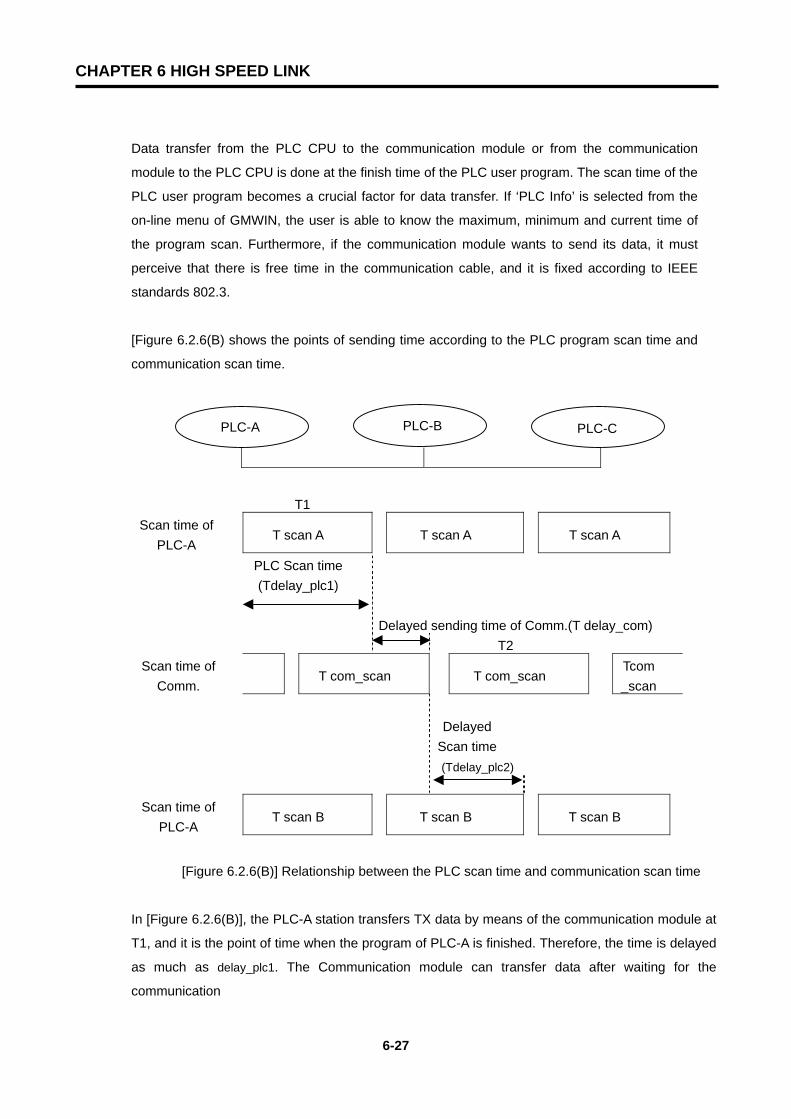
CHAPTER 6 HIGH SPEED LINK
6-27
Data transfer from the PLC CPU to the communication module or from the communication
module to the PLC CPU is done at the finish time of the PLC user program. The scan time of the
PLC user program becomes a crucial factor for data transfer. If ‘PLC Info’ is selected from the
on-line menu of GMWIN, the user is able to know the maximum, minimum and current time of
the program scan. Furthermore, if the communication module wants to send its data, it must
perceive that there is free time in the communication cable, and it is fixed according to IEEE
standards 802.3.
[Figure 6.2.6(B) shows the points of sending time according to the PLC program scan time and
communication scan time.
T1 Scan time of
PLC-A T scan A T scan A T scan A
PLC Scan time (Tdelay_plc1)
Delayed sending time of Comm.(T delay_com) T2
Scan time of Comm.
T com_scan T com_scan Tcom_scan
Delayed
Scan time (Tdelay_plc2)
Scan time of
PLC-A T scan B T scan B T scan B
[Figure 6.2.6(B)] Relationship between the PLC scan time and communication scan time
In [Figure 6.2.6(B)], the PLC-A station transfers TX data by means of the communication module at
T1, and it is the point of time when the program of PLC-A is finished. Therefore, the time is delayed
as much as delay_plc1. The Communication module can transfer data after waiting for the
communication
PLC-A PLC-B PLC-C

CHAPTER 6 HIGH SPEED LINK
6-28
scan delay time (Tdelay_com) after it receives data from the PLC. It can be delayed as much as
Tcom_Scan1 for the longest time delay. In PLC-B as well, as the communication module transfers the
received data to the PLC after waiting for 2 hours (Tdelay_plc2), a delay factor as much as a
maximum Tscan2 comes into existence. Like [Figure 6.2.6(A)] and [Figure 6.2.6(B)], the
Communication delay time is fixed according to a variety of factors such as total number of
communication stations, and program volume OS scan time of the communication module. Since it
is difficult to calculate the value of such factors, a method to easily calculated the time is presented
here.
2) Method for calculating the speed of the High Speed Link
The user defines the High Speed Link as the maximum time spent by a block of data from PLC-A to
PLC-B using an example like [Figure 6.2.7(B). It is calculated after you grouping the speed
calculation of the High Speed Link into a complicated system or a simple system. The complicated
systems more than 10 communication stations and sends data numbers 512 bytes. A simple
system has less than 10 communication stations, and the sending data numbers are under 512
bytes.
A) Simple system
The speed of the High Speed Link can be determined using the simple calculation system like
formula 6.2.6(A). The total number of communication stations is under 10, and the total volume of
the sending data is under 512 bytes.
St = P_ScanA + C_Scan + P_ScanB ------------------------ [Formula 6.2.6(A)]
(St = maximum transfer time of High Speed Link
P_ScanA = maximum program scan time of plc A
P_ScanB = maximum program scan time of plc B
C_Scan = maximum communication scan time)
Using formula 6.1, C_Scan can be determined with the following simple formula.
C_Scan = Th × Sn ------------------------------------------- [Formular 6.2.6(B)]
(Th = Time of data transfer from a media per 1 station (IEEE standards 802.3)
Sn = Total Station Number: Total Communication Number)
B) Complicated system
The speed of the High Speed Link can be calculated using the complicated calculation system
like formula 6.2.6(C). The total number of communication stations is over 10, and the volume of
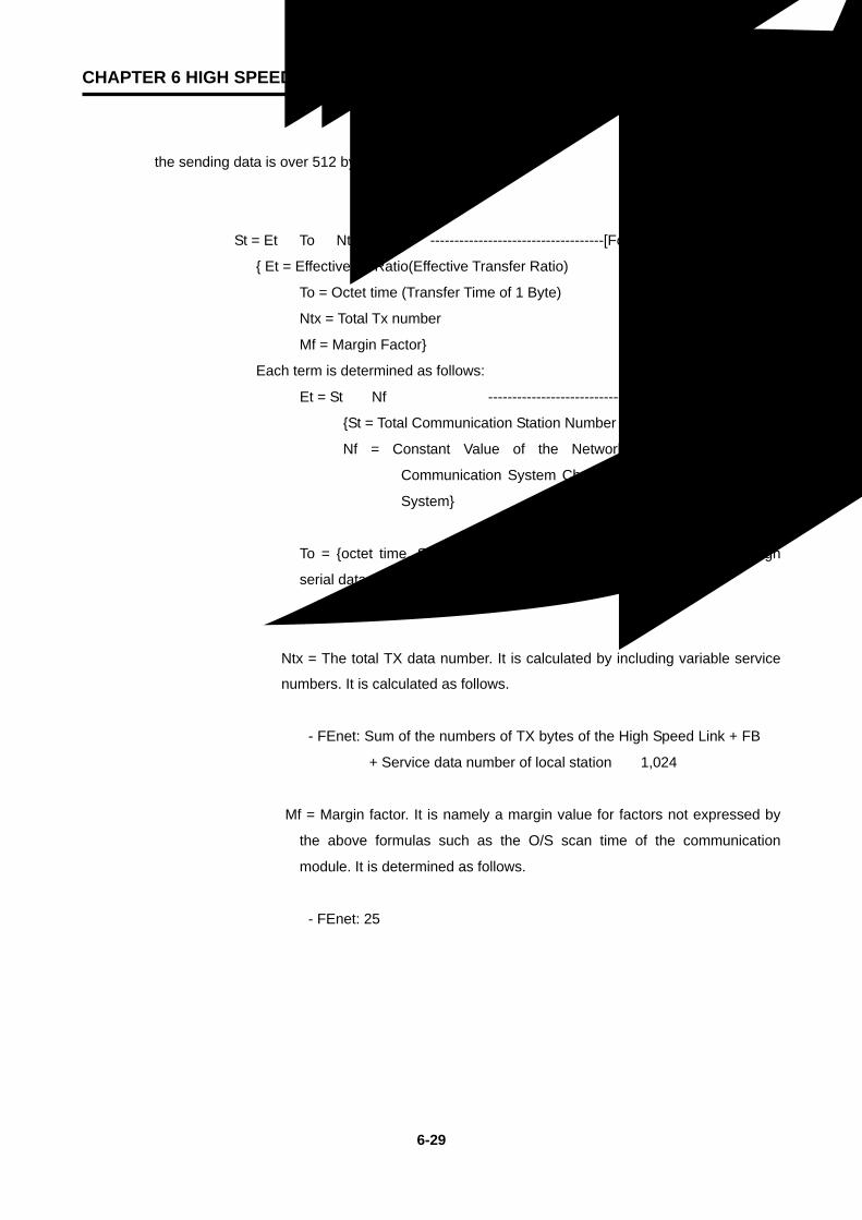
CHAPTER 6 HIGH SPEED LINK
6-29
the sending data is over 512 bytes.
St = Et ×To ×Ntx + Mf ------------------------------------[Formula 6.2.6(C)]
Et = Effective Tx Ratio(Effective Transfer Ratio)
To = Octet time (Transfer Time of 1 Byte)
Ntx = Total Tx number
Mf = Margin Factor
Each term is determined as follows:
① Et = St × Nf ----------------------------- [Formula 6.2.6(D)]
St = Total Communication Station Number
Nf = Constant Value of the Network Factor according to
Communication System Characteristics, and 1.5 in FEnet
System
② To = octet time. Spent time when 1 byte of data is transferred through
serial data. Its value is as follows:
- FEnet: 0.8
③ Ntx = The total TX data number. It is calculated by including variable service
numbers. It is calculated as follows.
- FEnet: Sum of the numbers of TX bytes of the High Speed Link + FB
+ Service data number of local station × 1,024
④ Mf = Margin factor. It is namely a margin value for factors not expressed by
the above formulas such as the O/S scan time of the communication
module. It is determined as follows.
- FEnet: 25
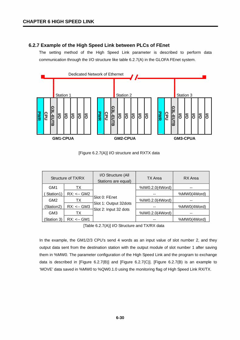
CHAPTER 6 HIGH SPEED LINK
6-30
6.2.7 Example of the High Speed Link between PLCs of FEnet The setting method of the High Speed Link parameter is described to perform data
communication through the I/O structure like table 6.2.7(A) in the GLOFA FEnet system.
Dedicated Network of Ethernet
Station 1 Station 2 Station 3
PWR
CPU
G3L-EU
TBI/O I/O I/O I/O I/O
PWR
CPU
G3L-EU
TBI/O I/O I/O I/O I/O
PWR
CPU
G3L-EU
TBI/O I/O I/O I/O I/O
GM1-CPUA GM2-CPUA GM3-CPUA
[Figure 6.2.7(A)] I/O structure and RXTX data
Structure of TX/RX I/O Structure (All
Stations are equal) TX Area RX Area
GM1 TX %IW0.2.0(4Word) -- ( Station1) RX: <-- GM2 -- %MW0(4Word)
GM2 TX %IW0.2.0(4Word) -- (Station2) RX: <-- GM3 -- %MW0(4Word)
GM3 TX %IW0.2.0(4Word) -- (Station 3) RX: <-- GM1
Slot 0: FEnet Slot 1: Output 32dots Slot 2: Input 32 dots
-- %MW0(4Word) [Table 6.2.7(A)] I/O Structure and TX/RX data
In the example, the GM1/2/3 CPU’s send 4 words as an input value of slot number 2, and they
output data sent from the destination station with the output module of slot number 1 after saving
them in %MW0. The parameter configuration of the High Speed Link and the program to exchange
data is described in [Figure 6.2.7(B)] and [Figure 6.2.7(C)]. [Figure 6.2.7(B) is an example to
‘MOVE’ data saved in %MW0 to %QW0.1.0 using the monitoring flag of High Speed Link RX/TX.
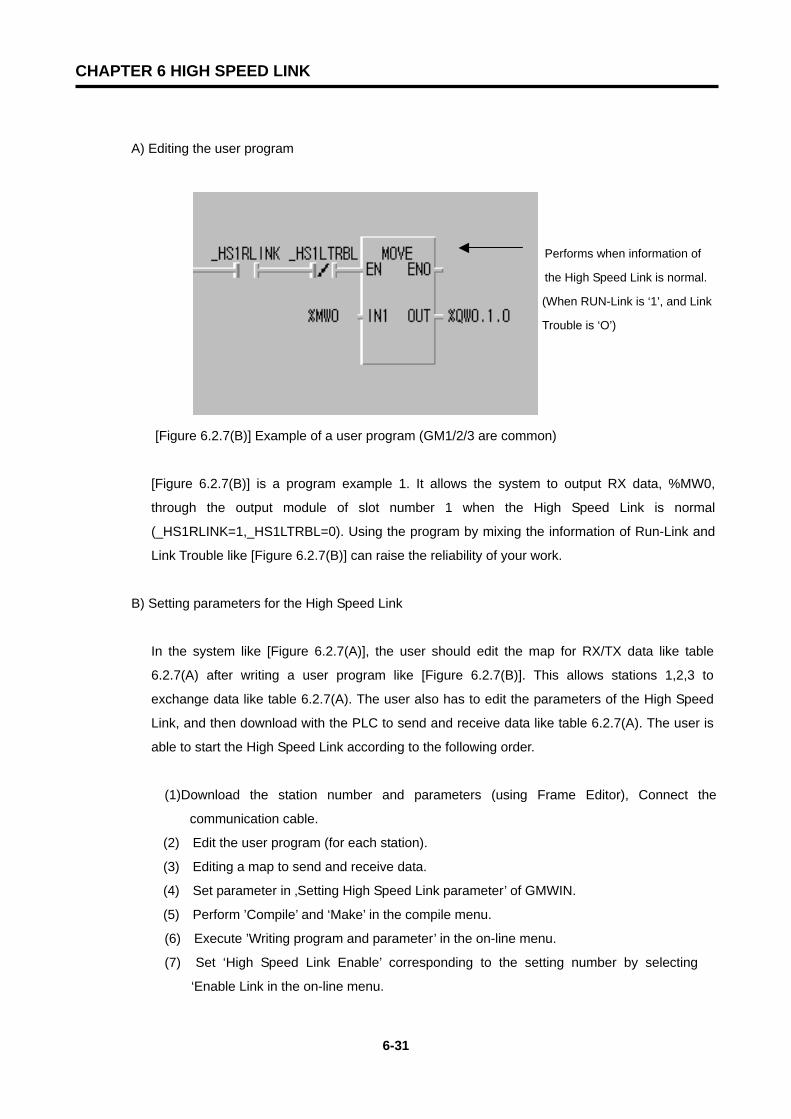
CHAPTER 6 HIGH SPEED LINK
6-31
A) Editing the user program
[Figure 6.2.7(B)] Example of a user program (GM1/2/3 are common)
[Figure 6.2.7(B)] is a program example 1. It allows the system to output RX data, %MW0,
through the output module of slot number 1 when the High Speed Link is normal
(_HS1RLINK=1,_HS1LTRBL=0). Using the program by mixing the information of Run-Link and
Link Trouble like [Figure 6.2.7(B)] can raise the reliability of your work.
B) Setting parameters for the High Speed Link
In the system like [Figure 6.2.7(A)], the user should edit the map for RX/TX data like table
6.2.7(A) after writing a user program like [Figure 6.2.7(B)]. This allows stations 1,2,3 to
exchange data like table 6.2.7(A). The user also has to edit the parameters of the High Speed
Link, and then download with the PLC to send and receive data like table 6.2.7(A). The user is
able to start the High Speed Link according to the following order.
(1)Download the station number and parameters (using Frame Editor), Connect the
communication cable.
(2) Edit the user program (for each station).
(3) Editing a map to send and receive data.
(4) Set parameter in ‚Setting High Speed Link parameter’ of GMWIN.
(5) Perform ’Compile’ and ‘Make’ in the compile menu.
(6) Execute ’Writing program and parameter’ in the on-line menu.
(7) Set ‘High Speed Link Enable’ corresponding to the setting number by selecting
‘Enable Link in the on-line menu.
Performs when information of
the High Speed Link is normal.
(When RUN-Link is ‘1’, and Link
Trouble is ‘O’)
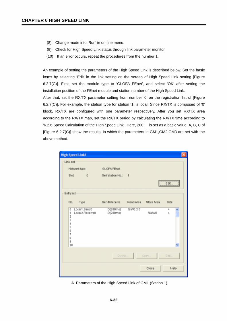
CHAPTER 6 HIGH SPEED LINK
6-32
(8) Change mode into ‚Run’ in on-line menu.
(9) Check for High Speed Link status through link parameter monitor.
(10) If an error occurs, repeat the procedures from the number 1.
An example of setting the parameters of the High Speed Link is described below. Set the basic
items by selecting ‘Edit’ in the link setting on the screen of High Speed Link setting [Figure
6.2.7(C)]. First, set the module type to ‘GLOFA FEnet’, and select ‘OK’ after setting the
installation position of the FEnet module and station number of the High Speed Link.
After that, set the RX/TX parameter setting from number ‘0’ on the registration list of [Figure
6.2.7(C)]. For example, the station type for station ‘1’ is local. Since RX/TX is composed of ‘0’
block, RX/TX are configured with one parameter respectively. After you set RX/TX area
according to the RX/TX map, set the RX/TX period by calculating the RX/TX time according to
‘6.2.6 Speed Calculation of the High Speed Link’. Here, 200 is set as a basic value. A, B, C of
[Figure 6.2.7(C)] show the results, in which the parameters in GM1,GM2,GM3 are set with the
above method.
A. Parameters of the High Speed Link of GM1 (Station 1)

CHAPTER 6 HIGH SPEED LINK
6-33
B. Parameters of the High Speed Link of GM2 (Station 2)
C. Parameters of the High Speed Link of GM3 (Station 3)
[Figure 6.2.7(C)] Examples of parameter settings for the High Speed Link
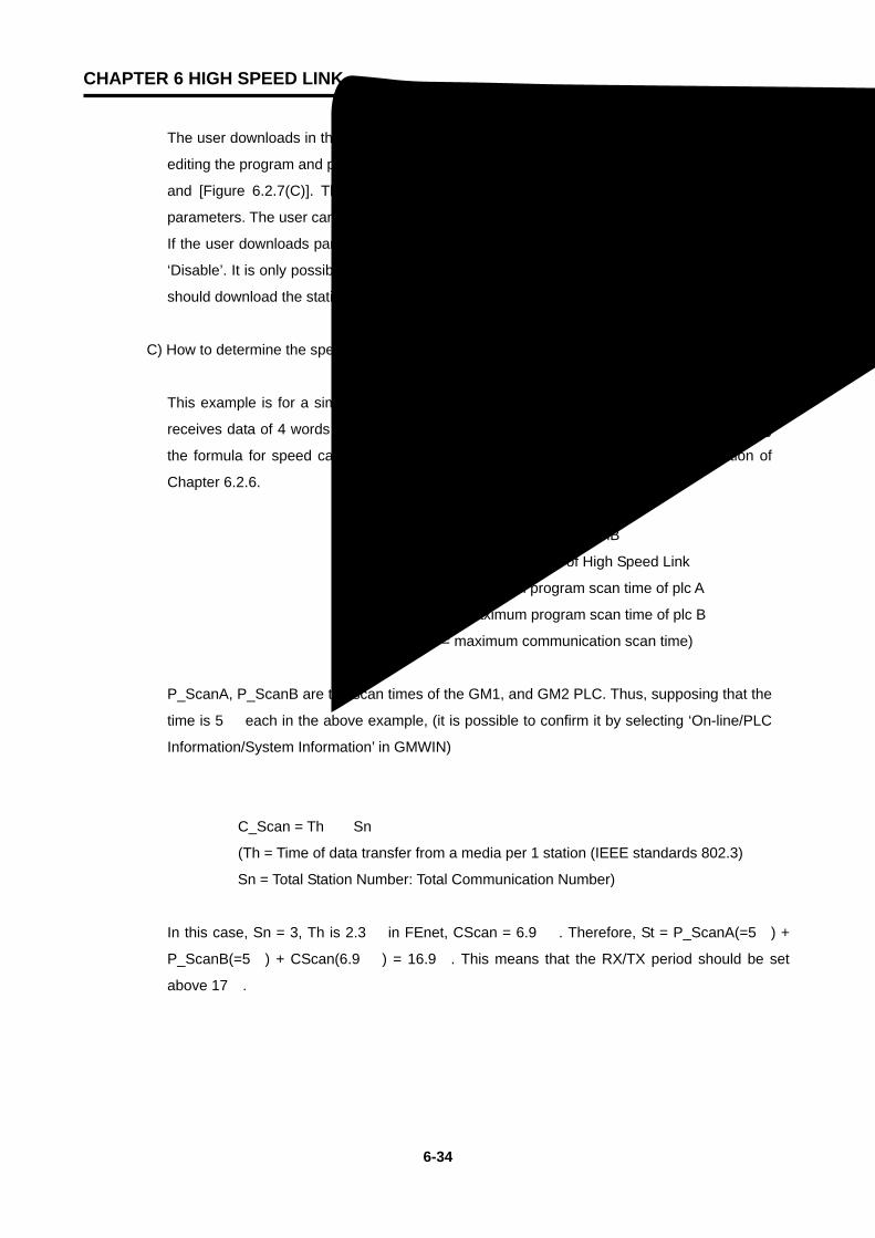
CHAPTER 6 HIGH SPEED LINK
6-34
The user downloads in the on-line menu into the appropriate PLC, and sets ‘Enable Link’ after
editing the program and parameters and ‘Compile’ in the compile menu like the [Figure 6.1.7(B)]
and [Figure 6.2.7(C)]. The High Speed Link begins to perform RX/TX according to the set
parameters. The user can start the system after turning on the PLC mode to ‘Run’.
If the user downloads parameters of the High Speed Link, ‘Enable Link’ automatically becomes
‘Disable’. It is only possible to set ‘Enable Link’ only during the stop mode of the PLC. (the user
should download the station number into the FEnet module for each CPU in Frame Editor)
C) How to determine the speed of the High Speed Link.
This example is for a simple system. The communication modules of 3 stations sends and
receives data of 4 words each. The period setting of RX/TX can be easily determined using
the formula for speed calculation for a simple system in the ‘Speed Calculation’ section of
Chapter 6.2.6.
St = P_ScanA + C_Scan + P_ScanB
(St = maximum transfer time of High Speed Link
P_ScanA = maximum program scan time of plc A
P_ScanB = maximum program scan time of plc B
C_Scan = maximum communication scan time)
P_ScanA, P_ScanB are the scan times of the GM1, and GM2 PLC. Thus, supposing that the
time is 5 each in the above example, (it is possible to confirm it by selecting ‘On-line/PLC
Information/System Information’ in GMWIN)
C_Scan = Th × Sn
(Th = Time of data transfer from a media per 1 station (IEEE standards 802.3)
Sn = Total Station Number: Total Communication Number)
In this case, Sn = 3, Th is 2.3 in FEnet, CScan = 6.9 . Therefore, St = P_ScanA(=5) +
P_ScanB(=5) + CScan(6.9 ) = 16.9. This means that the RX/TX period should be set
above 17.

CHAPTER 6 HIGH SPEED LINK
6-35
6.3 The Redundancy System of the High Speed Link
6.3.1 Introduction
The redundant system used by the FEnet module is a network redundancy that sends and receives
the same data at the same time with 2 networks configured by the FEnet module using
communication like [Figure 5.3(A)]. High Speed Link Redundancy of the redundant system
performs by adding special functions to the existing High Speed Link service. For the basic settings
of the High Speed Link and its operation, see section ‘6.2 High Speed Link’.
The difference between the redundant system and single system is as follows:
1) Communication length
Communication point to be set in a block of redundant CPU (GMR-CPUA) is fixed at a maximum
59 words in all networks of GLOFA.
Comparision of CPU with redundant
configuration
Redundant CPU (GMR-CPUA/B)
Redundancy of GM1/2/3 CPU
(GMx-CPUA,x=1,2,3)
In the case of single system
Maximum number of words to be set per block
59 words
200 words
200 words
[Table 6.3.1(A)] Communication length of a redundancy system per Block

CHAPTER 6 HIGH SPEED LINK
6-36
2) Communication data format
If the TX/RX area is set in the High Speed Link parameter and the block is used in the redundant
system, the serial number for the redundant process should be placed before the first word of the
data area.
A) Single system (Existing system: GM1/2/3/4)
Word number set per block: maximum 60 words
Data
Start point address of reading area when sending or saving area when receiving
B) Redundant system of the CPU (In the case of GMR-CPUA )
Word number set per block: maximum 59 words
Data
Serial Number(1Word) Start point address of reading area when sending or saving area when receiving
Automatically inserted when sending and automatically removed when receiving in the redundant CPU
Data format really sent and received (word number set per block + 1
Serial Number(1Word) Data
C) Communication with GMR-CPUA in GM1/2/3 CPU with network redundancy
Word number set per block: maximum 60 words
Serial Number(1Word) Data(Word number set per block-1)
Start point address of the data area for a user to communicate with

CHAPTER 6 HIGH SPEED LINK
6-37
In this serial number, 1 added value must be written in this place from the user program at every period of
RX/TX of the appropriate block when sending. When receiving, the serial number set from the partner
station’s CPU is recorded.
D) Communication with GM1/2/3/4 CPU in GM1/2/3 CPU with network redundancy
Word number set per block: maximum 200 words
Serial Number(1Word) Data(Word number set per block-1)
Start point address of the data area for a user to communicate with
In this serial number, 1 added value must be written in this place from the user program at every period of
RX/TX of the appropriate block when sending. When receiving, the serial number set from the partner
station’s CPU is recorded.
Point
1) When you perform High Speed Link through redundancy in the GM1/2/3 CPU system, %M area must be used.
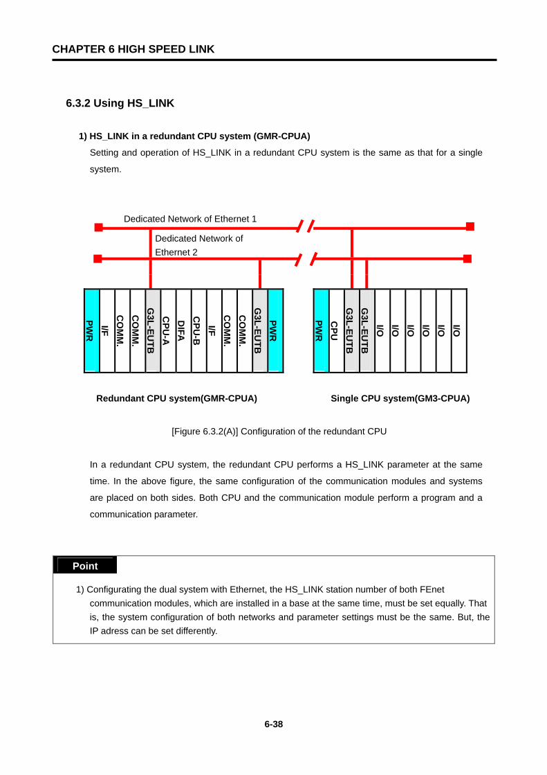
CHAPTER 6 HIGH SPEED LINK
6-38
6.3.2 Using HS_LINK
1) HS_LINK in a redundant CPU system (GMR-CPUA)
Setting and operation of HS_LINK in a redundant CPU system is the same as that for a single
system.
Dedicated Network of Ethernet 1
Dedicated Network of Ethernet 2
PWR
I/FC
OM
M.
CO
MM
.G
3L-EUTB
CPU
-AD
IFAC
PU-B
I/FC
OM
M.
CO
MM
.G
3L-EUTB
PWR
PWR
CPU
G3L-EU
TBG
3L-EUTB
I/O I/O I/O I/O I/O I/O
Redundant CPU system(GMR-CPUA) Single CPU system(GM3-CPUA)
[Figure 6.3.2(A)] Configuration of the redundant CPU
In a redundant CPU system, the redundant CPU performs a HS_LINK parameter at the same
time. In the above figure, the same configuration of the communication modules and systems
are placed on both sides. Both CPU and the communication module perform a program and a
communication parameter.
Point
1) Configurating the dual system with Ethernet, the HS_LINK station number of both FEnet communication modules, which are installed in a base at the same time, must be set equally. That is, the system configuration of both networks and parameter settings must be the same. But, the
IP adress can be set differently.

CHAPTER 6 HIGH SPEED LINK
6-39
- TX of HS_LINK
The TX of HS_LINK in a dual CPU system sends data by the communication module to the
TX area set in the parameters through each communication module. A serial number is
added at every period of TX. The serial number increases in accordance with the CPU
synchronization, and each block has its own serial number. Since the processing of the serial
number is automatically performed, no additional work is needed in the user program.
- RX of HS_LINK
For RX of HS_LINK, the serial number and the data from the communication module are
processed in each CPU. Processing of the serial number of RX data is automatically
performed. Therefore, no additional work is needed in the user program. The method to
process the RX data of each CPU is as follows. Each CPU allows the user to save the latest
data between two data (the data with the larger number of the two RX data) received through
communication module A and B from the other station. In case that the data of only one side
is received, it compares it with the current serial number. If the data is larger than that, they
will be saved.
- Processing HS_LINK Information
HS_LINK information registers the information made in the communication module A and B by
OR (operation) in the flag of HS_LINK information. If HS_LINK information monitor is executed,
the user can see the information of communication module A and B.
2) HS_LINK in a single CPU system (GM1/2/3)
Dedicated Network of Ethernet 1
Dedicated Network of Ethernet 2
PWR
I/FC
OM
M.
CO
MM
.G
3L-EUTB
CPU
-AD
IFAC
PU-B
I/FC
OM
M.
CO
MM
.G
3L-EUTB
PWR
PWR
CPU
G3L-EU
TBG
3L-EUTB
I/O I/O I/O I/O I/O I/O
Redundant CPU system(GMR-CPUA) Single CPU system(GM3-CPUA)
[Figure 6.3.2(B)] Configuration of a redundant system
CHAPTER 6 HIGH SPEED LINK
6-40
The parameters with the same contents are performed in two communication modules of a single
CPU system. In the above figure, two communication modules are installed and the
communication parameter with the same contents are processed in both communication
modules.
When setting the parameters in a single CPU system, take the following into account.
Point
1) The station numbers of the two FEnet communication modules are the same. (Both networks have the same configuration.) The IP address can be set the same or with as another Class.
2) You should assign HS_LINK in each communication module. (Example: 1 HS_LINK, 2 HS_LINKs.)
3) Setting of each block set in High-speed must be the same except for the RX area and slot number. 4) The RX area of the blocks set in both parameters should not be duplicated between two parameters. 5) The TX block number of the parameter set as a TX block must be at least 2 (including the serial
number).
- TX of HS_LINK
TX of HS_LINK sends data to each communication module after it fixes the serial number added
by each TX period in the TX area set from the parameter in a single CPU. For the serial number, the
data added at each TX should be written into the serial number position of the data in the user
program.
- RX of HS_LINK
RX of HS_LINK reads the received serial number and data from both sides. It compares their
serial numbers and then edits HS_FB to save the latest data (the one with the larger serial
number) of both data sets.
- Information Processing of the HS_LINK
Information processing of HS_LINK manages information of each communication module
used in HS_FB. It does not send abnormal data of _HSx_MODE,_HSx_RLINK,_HSx_TRX
between the two communication modules (between the two networks). Therefore, when
editing the user program, please edit it using the information flag of HS_LINK like the example
in Chap. 6.3.3, to ensure reliability.
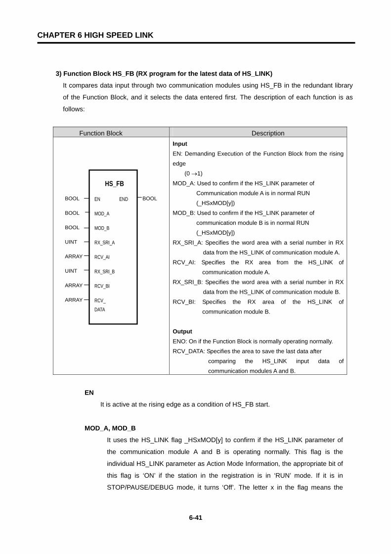
CHAPTER 6 HIGH SPEED LINK
6-41
3) Function Block HS_FB (RX program for the latest data of HS_LINK)
It compares data input through two communication modules using HS_FB in the redundant library
of the Function Block, and it selects the data entered first. The description of each function is as
follows:
Function Block Description
Input EN: Demanding Execution of the Function Block from the rising
edge
(0 →1)
MOD_A: Used to confirm if the HS_LINK parameter of
Communication module A is in normal RUN
(_HSxMOD[y])
MOD_B: Used to confirm if the HS_LINK parameter of
communication module B is in normal RUN
(_HSxMOD[y])
RX_SRI_A: Specifies the word area with a serial number in RX
data from the HS_LINK of communication module A.
RCV_AI: Specifies the RX area from the HS_LINK of
communication module A.
RX_SRI_B: Specifies the word area with a serial number in RX
data from the HS_LINK of communication module B.
RCV_BI: Specifies the RX area of the HS_LINK of
communication module B.
Output ENO: On if the Function Block is normally operating normally.
RCV_DATA: Specifies the area to save the last data after
comparing the HS_LINK input data of
communication modules A and B.
EN
It is active at the rising edge as a condition of HS_FB start.
MOD_A, MOD_B
It uses the HS_LINK flag _HSxMOD[y] to confirm if the HS_LINK parameter of
the communication module A and B is operating normally. This flag is the
individual HS_LINK parameter as Action Mode Information, the appropriate bit of
this flag is ‘ON’ if the station in the registration is in ‘RUN’ mode. If it is in
STOP/PAUSE/DEBUG mode, it turns ‘Off’. The letter x in the flag means the
HS_FB
EN END
MOD_A
MOD_B
RX_SRI_A
RCV_AI
RX_SRI_B
RCV_BI
RCV_
DATA
BOOL BOOL
BOOL
BOOL
UINT
ARRAY
UINT
ARRAY
ARRAY

CHAPTER 6 HIGH SPEED LINK
6-42
number of the currently used HS_LINK number. That is, when the editing the
HS_LINK parameter, it is possible to set from HS_LINK1 to HS_LINK4. It is for
setting parameter to each communication module because it is possible to install
up to communication modules into base board. User records currently used
HS_LINK (setting range ; x=1~4). In flag, you perform RX/TX toward each station
after editing total 64 individual parameters in HS_LINK parameter. The alphabet
y means the appropriate parameter number of RX parameter to be applied in the
current HS_LINK parameter.
RX_SRI_A, RX_SRI_B
It specifies the area of the serial number in the HS_LINK data received from
communication modules A and B. For example, communication module A receives
HS_LINK data sent from the other station from %MW10 to %MW20, When
communication module B receives data from %MW30 to %MW40, it writes the head
address of the received data because the serial number is fixed at the data head
sent from the other station to select them. In RX_SRI_A, as in the case of [Figure
6.3.3(B)], it defines %MW10 as the data position using variables such as
HS_RX_SRI_A (data type: UINT). In RX_SRI_B, it also defines %MW30 as the data
position using variables such as RX_SRI_B (data type: UINT).
RCV_AI, RCV_BI
It specifies the rest of head address in the HS_LINK data sent from the other station
except for the serial number. For example, when it receives data in communication
module A from %MW10 to %MW20, communication module B receives
from %MW30 to %MW40, as in the figure below. Data of the communication module
A specifies %MW11 to %MW20 as positioning using an ARRAY variable such as
RCV_A (data type:WORD), and communication module B specifies %MW31
to %MW40 as positioning using an ARRAY variable such as RCV_B (data
type:WORD).
ENO
’On’ when the Function Block is normal.
_RCV_DATA
It finally saves the data received after comparing the data’s serial number input from
two communication modules. As in the example, it specifies the position to be used
by the final user using the ARRAY variable such as HS_RDATA. (data type: WORD)
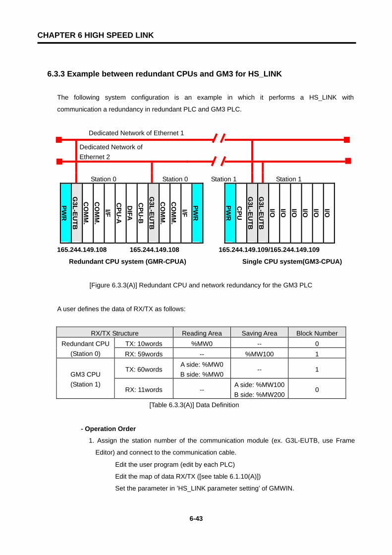
CHAPTER 6 HIGH SPEED LINK
6-43
6.3.3 Example between redundant CPUs and GM3 for HS_LINK
The following system configuration is an example in which it performs a HS_LINK with
communication a redundancy in redundant PLC and GM3 PLC.
Dedicated Network of Ethernet 1
Dedicated Network of Ethernet 2
Station 0 Station 0 Station 1 Station 1
PWR
G3L-EU
TBC
OM
M.
CO
MM
.I/F
CPU
-AD
IFAC
PU-B
G3L-EU
TBC
OM
M.
CO
MM
.I/F
PWR
PWR
CPU
G3L-EU
TBG
3L-EUTB
I/O I/O I/O I/O I/O I/O
165.244.149.108 165.244.149.108 165.244.149.109/165.244.149.109
Redundant CPU system (GMR-CPUA) Single CPU system(GM3-CPUA)
[Figure 6.3.3(A)] Redundant CPU and network redundancy for the GM3 PLC
A user defines the data of RX/TX as follows:
RX/TX Structure Reading Area Saving Area Block Number TX: 10words %MW0 -- 0 Redundant CPU
(Station 0) RX: 59words -- %MW100 1
TX: 60words A side: %MW0 B side: %MW0
-- 1 GM3 CPU (Station 1)
RX: 11words -- A side: %MW100 B side: %MW200
0
[Table 6.3.3(A)] Data Definition
- Operation Order
1. Assign the station number of the communication module (ex. G3L-EUTB, use Frame
Editor) and connect to the communication cable.
① Edit the user program (edit by each PLC)
② Edit the map of data RX/TX ([see table 6.1.10(A)])
③ Set the parameter in ’HS_LINK parameter setting’ of GMWIN.
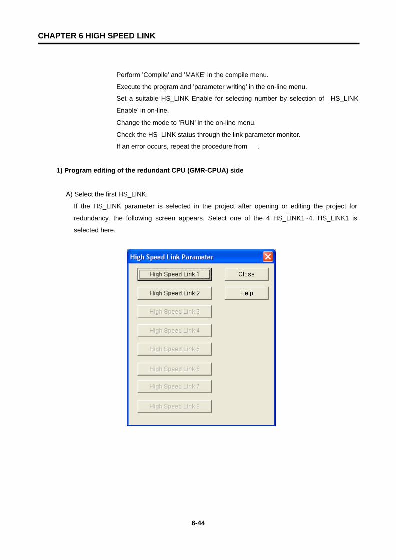
CHAPTER 6 HIGH SPEED LINK
6-44
④ Perform ’Compile’ and ’MAKE’ in the compile menu.
⑤ Execute the program and ’parameter writing’ in the on-line menu.
⑥ Set a suitable HS_LINK Enable for selecting number by selection of‘HS_LINK
Enable’ in on-line.
⑦ Change the mode to ’RUN’ in the on-line menu.
⑧ Check the HS_LINK status through the link parameter monitor.
⑨ If an error occurs, repeat the procedure from ①.
1) Program editing of the redundant CPU (GMR-CPUA) side
A) Select the first HS_LINK.
If the HS_LINK parameter is selected in the project after opening or editing the project for
redundancy, the following screen appears. Select one of the 4 HS_LINK1~4. HS_LINK1 is
selected here.
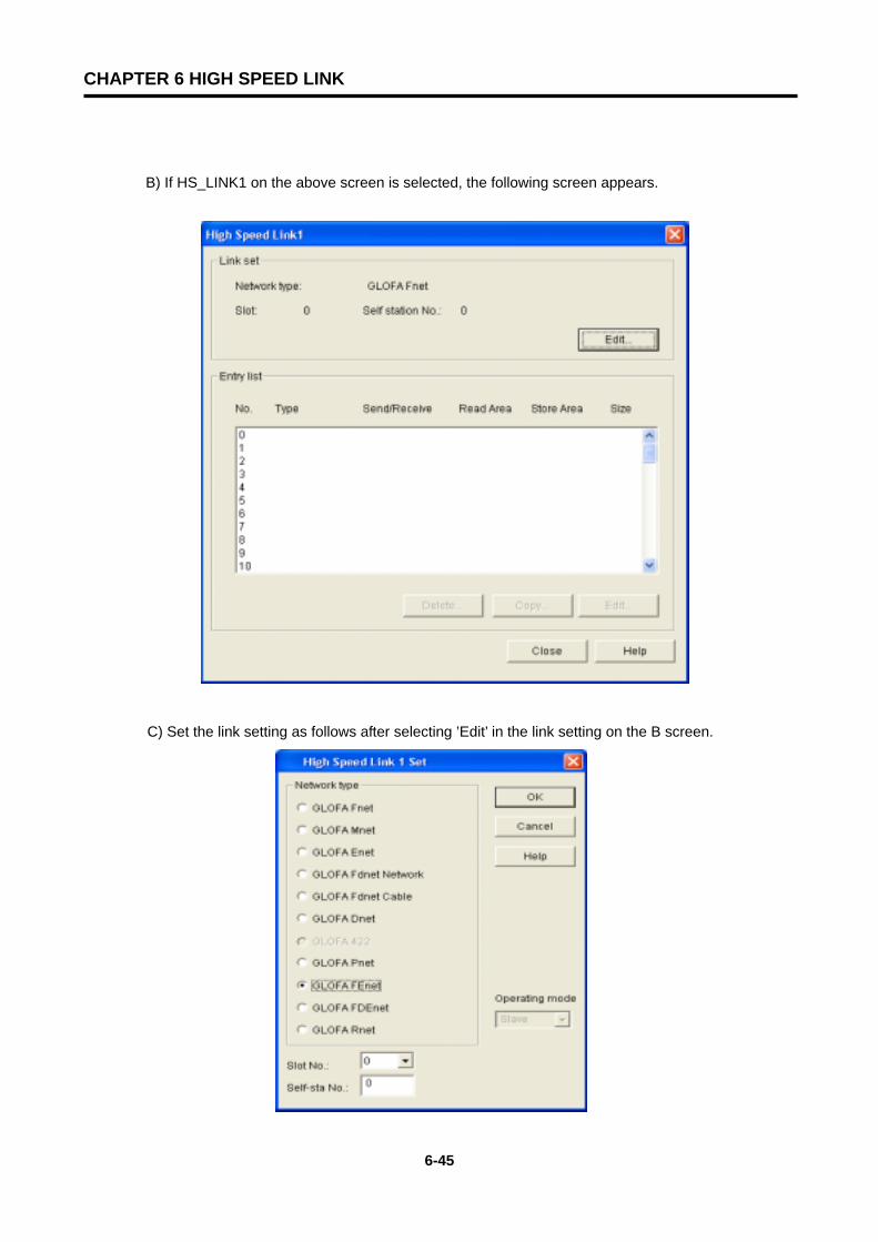
CHAPTER 6 HIGH SPEED LINK
6-45
B) If HS_LINK1 on the above screen is selected, the following screen appears.
C) Set the link setting as follows after selecting ’Edit’ in the link setting on the B screen.

CHAPTER 6 HIGH SPEED LINK
6-46
D) Set the RX/TX parameter after selecting number 0 in the registration list.
For the TX parameter
For the RX parameter

CHAPTER 6 HIGH SPEED LINK
6-47
E) The following is set if operation 1 to 2 is executed.
F) Now, select ’Close’ after setting the HS_LINK parameter . Write the PLC program after editing
the user program and executing ’Compile -> Build All’.
G) Confirm whether the communication for the set parameter is normally operating by selecting
’On-line/Link parameter’ and Monitor/HS_LINK1 after changing the PLC mode to RUN (the
appropriate program and HS_LINK parameter in the other station must be normally operating
after the download as well).

CHAPTER 6 HIGH SPEED LINK
6-48
In the above screen, if the communication of the ‘Run Link’ mode is ‘1’, and ‘Link Trouble is
‘0’, this means that there is normal communication status. The above screen shows that the
communication with the other station is normal. To confirm the value to be communicated,
select the direct variable %MW100 in ’On-line/Monitor/Variable Monitor’.
2) Program editing of the GM3
A) Select HS_LINK.
Select the HS_LINK parameter in the project after opening or editing the new project for GM3.
The following screen appears. Select one of 4 HS_LINK1~4. High Speed Link 1 is selected to
define the first module of the 2 FEnet communication module.
In ’1(1,1)’, the left ’1’ inside the parenthesis is thecommunication status of the communicationmodule installed in the left GMR-CPUA. Theright ’1’ inside the parenthesis is thecommunication status of the communicationmodule installed in the right GMR-CPUA. The‘1’ outside the parenthesis is the value which theoperating (OR) status of the inside parenthesisindicates.

CHAPTER 6 HIGH SPEED LINK
6-49
B) If you select High Speed Link 1 in the above screen, the following screen will appear.
C) Select ‘OK’ after the link setting as follow and select ’Edit’ on the previous screen.

CHAPTER 6 HIGH SPEED LINK
6-50
D) Set the RX/TX parameter after selecting number 0 in the registration list.
For TX Parameter
For RX Parameter (Selecting 1 in the registration list)
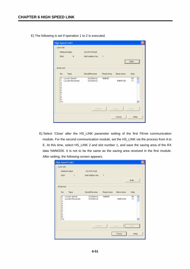
CHAPTER 6 HIGH SPEED LINK
6-51
E) The following is set if operation 1 to 2 is executed.
E) Select ’Close’ after the HS_LINK parameter setting of the first FEnet communication
module. For the second communication module, set the HS_LINK via the process from A to
E. At this time, select HS_LINK 2 and slot number 1, and save the saving area of the RX
data %MW200. It is not to be the same as the saving area received in the first module.
After setting, the following screen appears.
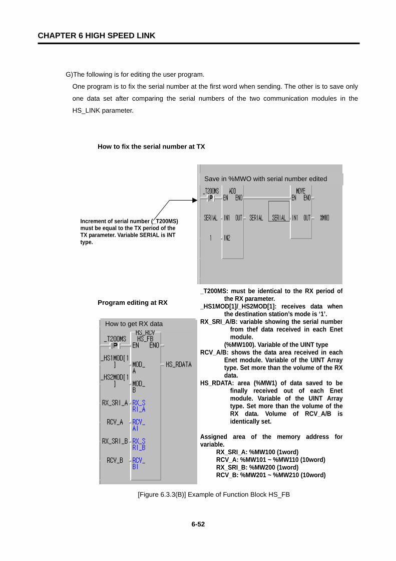
CHAPTER 6 HIGH SPEED LINK
6-52
G)The following is for editing the user program.
One program is to fix the serial number at the first word when sending. The other is to save only
one data set after comparing the serial numbers of the two communication modules in the
HS_LINK parameter.
How to fix the serial number at TX
Program editing at RX
[Figure 6.3.3(B)] Example of Function Block HS_FB
Increment of serial number (_T200MS)must be equal to the TX period of the TX parameter. Variable SERIAL is INT type.
_T200MS: must be identical to the RX period ofthe RX parameter.
_HS1MOD[1]/_HS2MOD[1]: receives data whenthe destination station’s mode is ‘1’.
RX_SRI_A/B: variable showing the serial numberfrom thef data received in each Enetmodule.
(%MW100). Variable of the UINT type RCV_A/B: shows the data area received in each
Enet module. Variable of the UINT Arraytype. Set more than the volume of the RXdata.
HS_RDATA: area (%MW1) of data saved to befinally received out of each Enetmodule. Variable of the UINT Arraytype. Set more than the volume of theRX data. Volume of RCV_A/B isidentically set.
Assigned area of the memory address forvariable.
RX_SRI_A: %MW100 (1word) RCV_A: %MW101 ~ %MW110 (10word) RX_SRI_B: %MW200 (1word) RCV_B: %MW201 ~ %MW210 (10word)
Save in %MWO with serial number edited
How to get RX data
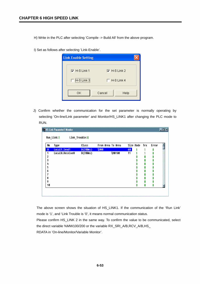
CHAPTER 6 HIGH SPEED LINK
6-53
H) Write in the PLC after selecting ’Compile -> Build All’ from the above program.
I) Set as follows after selecting ’Link-Enable’.
J) Confirm whether the communication for the set parameter is normally operating by
selecting ’On-line/Link parameter’ and Monitor/HS_LINK1 after changing the PLC mode to
RUN.
The above screen shows the situation of HS_LINK1. If the communication of the ‘Run Link’
mode is ‘1’, and ‘Link Trouble is ‘0’, it means normal communication status.
Please confirm HS_LINK 2 in the same way. To confirm the value to be communicated, select
the direct variable %MW100/200 or the variable RX_SRI_A/B,RCV_A/B,HS_
RDATA in ’On-line/Monitor/Variable Monitor’.

CHAPTER 7 GMWIN FUNCTION BLOCK
7-1
CHAPTER 7 GMWIN FUNCTION BLOCK
7.1 Overview
The Function Block is used to communicate between Ethernet communication modules of the local station and the destination station. It can also be used for communications between multiple stations using TCP/IP or UDP/IP. There are two methods to communicate using the Function Block. The single communication method uses only the Function Block to communicate independently. The user-defined communication method uses Frame Editor. This chapter describes the kind of Function Blocks provided to the user and their uses. The following displays the program editing order when using Function Block.
Parameter/Frame Editing
1 Writing after Frame Editor editing
Project
2 Generating or Opening Program
Writing Program
3 Writing Program with LD / IL
Compile/Make
4 Compile or Make
On-line Connection 5 Connection
On-line/Writing
6 Parameters and
Program
On-line/Mode Switchover 7 RUN Operation Mode
Apply 1 to 7 process to the
Destination Station.
Download into the FEnet module after editing the IP Address, HS_LINK, Station Number, Subnet Mask, Gateway address, Frame, etc using Frame Editor (when using Frame, switch CPU to Stop mode, then switch power on again.)
Write project and program on the GMWIN screen or opening the existing project, and program.
Confirm the I/P address of the communication module of the user’s station and parter station. HS_LINK station number, slot position, etc. and write a program for an emergency using the proper flag.
Confirm the action of the status of the program using the monitoring function when it is started. If an error occurs, determine the cause of the error using the STATUS value in the Function Block.

CHAPTER 7 GMWIN FUNCTION BLOCK
7-2
7.2 How to Use Function Blocks
1) FEnet Function Blocks The Function Block can be divided into 5 types according to its service.
Function Block Types Services
E_CONN When you establish a logical communication channel with the destination station.
TCP_SEND Sending data from the local station to the destination station using TCP/IP.
TCP_RCV Receiving data sent by the destination station using TCP/IP.
UDP_SEND Sending data from the local station to the destination station using UDP/IP.
UDP_RCV Receiving data sent by the destination station using UDP/IP. [Table 7.1.2] Types of Function Block
2) Structure of a Function Block Following figure displays Function Block Structure.
* Output results can be shown on the left according the Function Block.
Output the results of the
Function Block execution. Conditions to input the
Function Block execution.
Instance name (the name given to
distinguish various Function Blocks or the
Function Blocks with the same function).
Name of the
Function Block
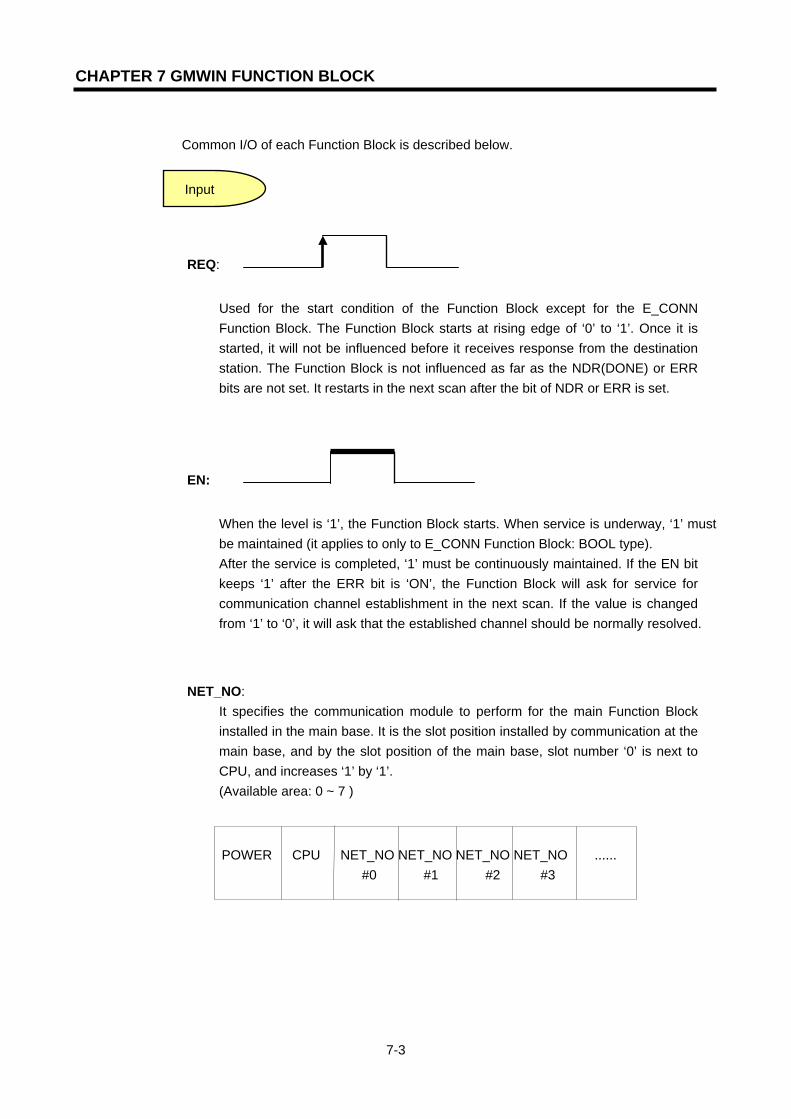
CHAPTER 7 GMWIN FUNCTION BLOCK
7-3
Common I/O of each Function Block is described below.
REQ:
Used for the start condition of the Function Block except for the E_CONN Function Block. The Function Block starts at rising edge of ‘0’ to ‘1’. Once it is started, it will not be influenced before it receives response from the destination station. The Function Block is not influenced as far as the NDR(DONE) or ERR bits are not set. It restarts in the next scan after the bit of NDR or ERR is set.
EN:
When the level is ‘1’, the Function Block starts. When service is underway, ‘1’ must be maintained (it applies to only to E_CONN Function Block: BOOL type). After the service is completed, ‘1’ must be continuously maintained. If the EN bit keeps ‘1’ after the ERR bit is ‘ON’, the Function Block will ask for service for communication channel establishment in the next scan. If the value is changed from ‘1’ to ‘0’, it will ask that the established channel should be normally resolved.
NET_NO: It specifies the communication module to perform for the main Function Block installed in the main base. It is the slot position installed by communication at the main base, and by the slot position of the main base, slot number ‘0’ is next to CPU, and increases ‘1’ by ‘1’. (Available area: 0 ~ 7 )
POWER CPU NET_NO NET_NO NET_NO NET_NO ...... #0 #1 #2 #3
Input

CHAPTER 7 GMWIN FUNCTION BLOCK
7-4
IP_ADDR: The IP address of the communication module of the destination station or the local station. It specifies the IP address necessary when communicating or establishing a channel. It needs the IP address of the destination station or the local station according to the Function Block (Please refer to each Function Block).
Example) ‘150.150.42.150’
D_PORT:
The port number of the destination station’s communication module (Setting between
h’400 - h’7fff).
SD_PORT:
The port number of communication module of the local station (Setting between h’400 -
h’7fff).
CH_NO: The channel number to be established (selected by user).
Able to select at least 16 channels from channel number ‘0’ up to ‘16’, It is not possible to use the same channel number for two Function Blocks within a program.
ARR_CNT/DATA:
The data volume to be sent and received. The volume of transferred frame can be up
to 1,400 bytes. However, for the redundant system of GMR, the volume of
transferred frame is limited to 120 bytes.
NDR: After the Function Block is started, and data is received normally, it turns ON and then it turns OFF until the next Function Block is started.
ERR : After the Function Block is started, and an error occurs, it turns ON, when the next Function Block is started. If an error occurs, data is not received. (For error codes, refer to the appendix ‘ A3. Error Code’).
STATUS : After the Function Block is started, and an error occurs, the ERR turns ON, and a
Output

CHAPTER 7 GMWIN FUNCTION BLOCK
7-5
detail code value of the error will be displayed. It keeps its value until the next Function Block is started.
Point
Requirements of the Function Block
1) The Requirements (REQ) of the Function Block should be restarted after the previous
execution is normally completed (after ‘NDR’ turns ON).
REQ
NDR
Under communication = internal processing time + response wait time (internal processing time: about 50 ~ 60ms)
Previous Execution Next Execution

CHAPTER 7 GMWIN FUNCTION BLOCK
7-6
7.3 Types of Function Blocks
7.3.1 E_CONN
Function Block Dexcription
Input EN: The Function Block is executed when the level
is ‘1’, and it must keep ‘1’ to remain in service.
NET_NO: Slot number (0 to 7), where the
communication module is installed. This is
where the Function Block is transferred.
IP_ADDR: The IP address of the the destination station
when establishing a channel as TCP_ACTIVE.
Establishing a chhannel as TCP_PASSIVE, it uses
the module’s IP address.
SD_PORT: When establishing a channel, it uses port
of destination station with TCP_ACTIVE, and it
uses port of the local station with
TCP_PASSIVE.
METHOD: When establishing a channel, It
determines system to activate with TCP or
UDP, Client or Server. (See the description
below)
CH_NO: Channel number to be established. ( 0~15 ) Output
NDR: It turns ‘ON’ at normal channel establishment.
ERR: It turns ‘ON’ at error occurrence after Function
Block is executed.
STATUS: It is a detailed code value of an error.
CH_EN: Results of channel establishment. It turns ‘ON’ at normal channel establishment.
A Function Block is used when you establish a logical communication channel with the destination station. There are five ways to establish the logical channel in Ethernet communication. The setting method depends on the each system service is as follows (IP_ADDR, SD_PORT, METHOD).
Product GMR GM1/2 GM3 GM4 GM6 GM7
Applicability n n n n n
Establishing logical communication channel with the destination station

CHAPTER 7 GMWIN FUNCTION BLOCK
7-7
1) TCP_ACTIVE
The destination station’s port (Dest Port) + the destination station’s IP address (Dest IP_ADDR).
A channel to use TCP/IP, and it specifies the destination station for communication. When communicating with the destination station, the local station is acting as the ‘Client’.
GLOFA 이더넷 모듈(자국)MMI 기기(PC등)
GLOFA 이더넷 모듈(타국)
또는 타사 이더넷 모듈
상대국에 데이터 요구
응답
Server
2) TCP_PASSIVE The local station (Source Port) + the IP address of the local station (Source IP_ADDR). A channel to use TCP/IP, and it is established for the station that demands its establishment the earliest. This means that the local station is acting as the ‘Server’ when communicating with the specified destination station.
GLOFA 이더넷 모듈(자국) MMI 기기(PC등)GLOFA 이더넷 모듈(타국)또는 타사 이더넷 모듈
상대국에서 데이터 요구
응답
Client
2) TCP_SELECT
The port of the local station (Source Port) + the IP address of the destination station (Dest IP_ADDR) A kind of TCP_PASSIVE. The channel is established only for the destination station specified by the user. The local station is acting as the ‘Server’ when communicating with the specified destination station.
3) UDP_ACTIVE
The port of the local station (Source Port) + the IP address of the local station (Source IP_ADDR) A channel to use UDP/IP. It only opens a ‘Socket’. The local station is acting as the
ClientServer
GLOFA Ethernet module Self Station
Request Data forDestination station
Response
GLOFA Ethernet module/Other company Ethernet
HMI(like a PC)
ServerClint Request Data forDestination station
Response
GLOFA Ethernet module
Self Station
GLOFA Ethernet module/
Other company Ethernet HMI(like a PC)
Client

CHAPTER 7 GMWIN FUNCTION BLOCK
7-8
‘Client’ when communicating with the specified destination station (It actually has no relation with the channel).
4) UDP_PASSIVE
The port of the local station (Source Port) + the IP address of the local station (Source IP_ADDR) A channel to use UDP/IP. It only binds a ‘Socket’. The local station is acting as the ‘Server’ when communicating with the specified destination station (It actually has no relation with the channel).
Point
1) ‘PASSIVE(SELECT) OPEN’ must be started earlier than ‘ACTIVE OPEN’. UDP_ACTIVE, UDP_PASSIVE connects internally only with the ’Socket’ open without establishing a channel
through service.
Therefore, the user should establish a suitable channel for the communication characteristics according to the types of logical channel establishment. The value of METHOD during Function Block input requires the channel establishment.
METHOD: ‘XXX_YYY(or ‘XXX_YYY_TTT’) - (Within 16 letters: String)
XXX: Shows the name of the group set by Frame Editor. YYY: The type of channel establishment. There are 5 kinds: TCPACT, TCPPAS, TCPSEL, UDPACT, UDPPAS. TTT: RX/TX latency time for channel release. (0~FF seconds). It cuts the connection by force if there is no response from the partner within the fixed time. (In case of TCPPAS)
XXX ‘UNFMT’ in XXX: Used to communicate without using Frame Editor when
performing data TX/RX. It sends and receives data without changing the Function Block data set by a user after an Ethernet communication connection. Therefore, if you bind the channel in the form of ‘UNFMT_YYY’ in the METHOD input of E_CONN, you must specify ‘_UDATA_SEND’ (TX) or ‘_UDATA_RCV’ (RX) in ‘FRAME’ within the TCP_SEND (UDP_SEND) or TCP_RCV (UDP_RCV) Function Block. After this, it is ready to be used.
A Program Example: When demanding a connection with TCP ACTIVE from the destination station.
In this case, the user demands a connection from the destination station (GLOFA) with 165.244.149.190 as its IP address and 5000 as the port number for the FEnet I/Fmodule. The FEnet module of the local station is installed in the number ‘0’ slot. In this case, it uses the number ‘1’ channel.
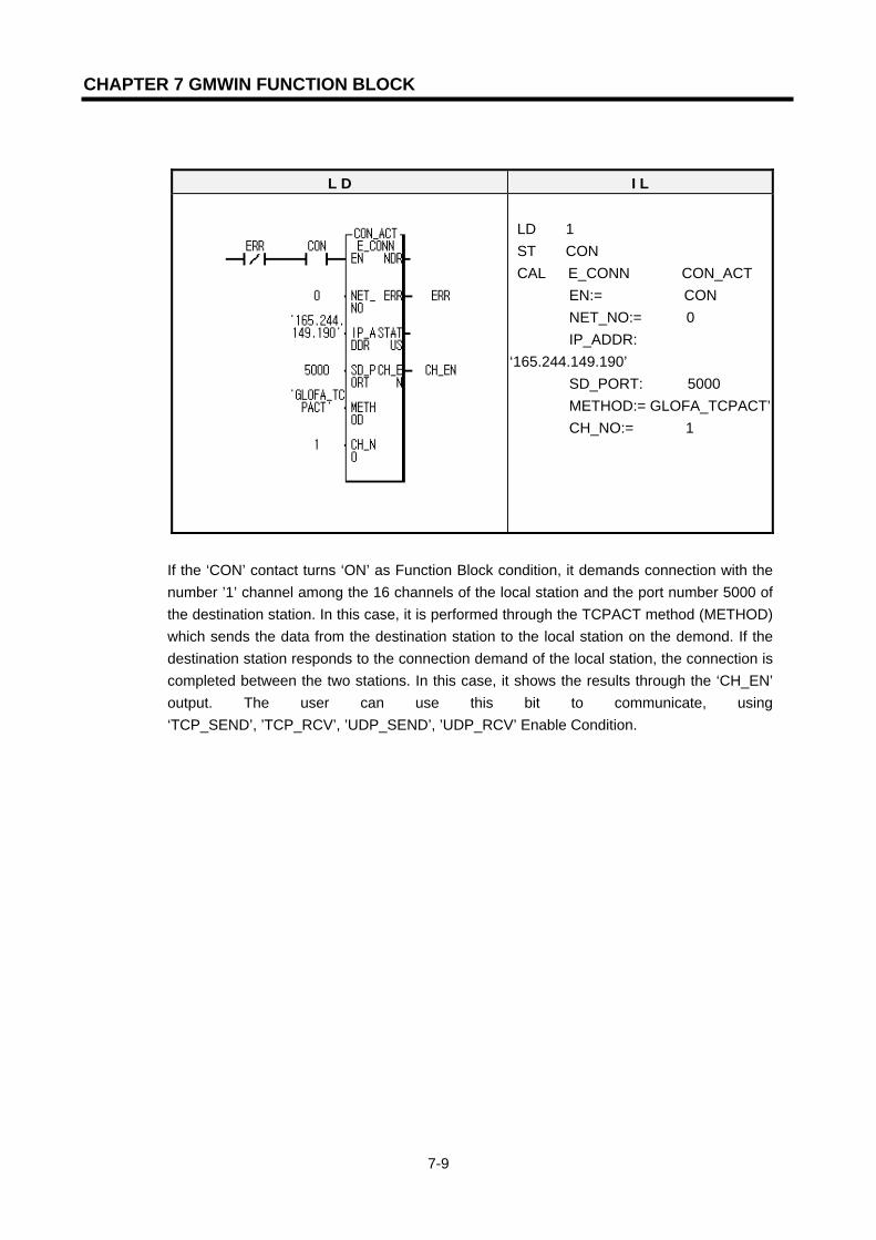
CHAPTER 7 GMWIN FUNCTION BLOCK
7-9
L D I L
LD 1 ST CON CAL E_CONN CON_ACT EN:= CON NET_NO:= 0 IP_ADDR: ‘165.244.149.190’ SD_PORT: 5000 METHOD:= GLOFA_TCPACT’ CH_NO:= 1
If the ‘CON’ contact turns ‘ON’ as Function Block condition, it demands connection with the number ’1’ channel among the 16 channels of the local station and the port number 5000 of the destination station. In this case, it is performed through the TCPACT method (METHOD) which sends the data from the destination station to the local station on the demond. If the destination station responds to the connection demand of the local station, the connection is completed between the two stations. In this case, it shows the results through the ‘CH_EN’ output. The user can use this bit to communicate, using ‘TCP_SEND’, ’TCP_RCV’, ’UDP_SEND’, ’UDP_RCV’ Enable Condition.

CHAPTER 7 GMWIN FUNCTION BLOCK
7-10
7.3.2 TCP_SEND
Product GMR GM1/2 GM3 GM4 GM6 GM7
Applicability n n n n n
펑션블록 설 명
Input REQ: Function Block is executed when it is at rising edge (0
→1),
NET_NO: The slot number (0 to 7), where the
communication module of the local station is installed.
This is where the Function Block is transferred.
CH_NO: Channel Number edited in the E_CONN Function
Block.
FRAME: Frame to be sent (distinguished with capital/small
letter). It uses the same name used in Frame Editor.
DATA_LEN: Number of data to be sent. Number of data types
equivalent to ‘DATA’.
DATA: An area saving TX data. Uses ‘ARRAY’. Output
NDR: It turns ‘ON’ at normal service.
ERR: It turns ‘ON’ at error occurrence after the Function
Block is executed. STATUS: It is a detailed code value of an error.
TCP_SEND is used to send data of the local station to the destination station using TCP/IP. It sends the data to the destination station installed with the ‘CH_NO’ channel in the form specified in ‘FRAME’ after reading ‘DATA’ to ‘DATA_LEN’. The name entered in ‘FRAME’ must be the same as the one in the TX/RX format that was defined in Frame Editor. If service is normal, the NDR bit turns to ‘Set’. When an error occurs, ERR turns to ‘Set’, and the code value according to such a result is saved in STATUS (for the STATUS code, see the section ‘A3, Error Code’ of the appendix). If the user wants to send data defined with a certain specified format, the frame name set in Frame Editor can be used. However, if the user directly sends user data directly by the single communication method without a frame format set in Frame Editor, the frame name ‘_UDATA_SEND’ must be used. That is, if the user uses the name ‘_UDATA_SEND’ in ‘Frame’ of the Function Block’, it does not send data with the frame name defined in Frame Editor. It sends the contents set in ‘DATA’ of the Function Block directly to the destination station after reading data to ‘ARR_CNT’. If the user wants to use the frame name ‘_UDATA_SEND’, the user should set a channel using a string value named ‘UNFMT_TCPxxx’ in ‘METHOD’ in the E_CONN Function Block. (xxx is ACT or PAS).
Used to send data to the destination
station using TCP/IP

CHAPTER 7 GMWIN FUNCTION BLOCK
7-11
A Program Example: When sending data to the destination station using TCP/IP.
In this case, the FEnet I/F module of the local station is installed in slot number ‘0’ , and the user sends data to the destination station using channel number ‘1’ (It is assumed that channel number ‘1’ is established using E_CONN Function Block).
L D I L
LD CH_EN CALC TCP_SEND ……... TCP_SEND REQ:= ……………. SEND NET_NO:= ……….. 0 CH:= ………………. 1 FRAME:=…………’SEND_FRAME’ ARR_CNT:= ……… 10 DATA:=……………..S_DATA
In this program, CH_EN is a result of channel establishment in the E_CONN Function Block. It is used as a contact to send data if the channel is established. ‘SEND_FRAME’ is a frame to be sent. It must be downloaded in the FEnet module using Frame Editor. 10(ARR_CNT) is the number of data to be sent, and it is also the number of S_DATA types. S_DATA is an ARRAY variable where sent data is saved.
.
SEND CH_EN
CH_NO STATUS
ERR
NDR
DATA
ARR_CNT
FRAME
NET_NO
REQ
TCP_SEND
‘SEND_FRAME’
TCP_SEND
0
S_DATA
10
1

CHAPTER 7 GMWIN FUNCTION BLOCK
7-12
7.3.3 TCP_RCV
Product GMR GM1/2 GM3 GM4 GM6 GM7
Applicability n n n n n
Funtion Block Description
Input REQ: When it is at the rising edge (0→1), the Function Block
is executed.
NET_NO: Slot number (0 to 7), where the communication
module of the local station is installed, and where
the Function Block is transferred.
CH_NO: Channel edited in the E_CONN Function Block.
FRAME: Frame to be received (distinguished with
capital/small letters). It must be downloaded in the
FEnet module after editing in Frame Editor.
DATA-LEN: Number of data to be received. Number of data
types equivalent to ‘DATA.
DATA: An area saving RX data. Uses ‘ARRAY’. Output
NDR: It turns ‘ON’ during normal service.
ERR: It turns ‘ON’ during error occurance after the Function
Block is executed.
STATUS: It is a detail code value of an error. RCV-LEN: The number of data received.
This TCP_RCV Funcrtion Block is used to receive data from the destination station using TCP/IP. It starts at the rising edge of REQ, and the data is received through the communication module of the local station installed number CH_NO of the main base. CH_NO is a channel set when establishing a channel with the destination station in the E_CONN Function Block. The data name that comes into FRAME specifies the frame name downloaded into the Ethernet communication module. It receives only if the data received from the destination station are the same as defined frame. RCV_LEN shows data numbers received from destination station after saving them. If the user wants to receive data with a certain specified format, the frame name set in Frame Editor can be used. However, if the user receives data directly by the single communication method without frame format set in Frame Editor, the frame name ‘_UDATA_RCV’ in the frame must be used. That is, if the user uses the name ‘_UDATA_RCV’ in ‘Frame’ of the Function Block, it does not receive data with the frame name defined in Frame Editor. It saves the data sent from the destination station in ‘DATA’ after reading the data as ara as ‘DATA_LEN. If the user wants to use the frame name ‘_UDATA_RCV’, a channel using a string value named ‘UNFMT_TCPxxx’ in ‘METHOD’ in the E_CONN Function Block (xxx is ACT or PAS) should be set.
Used to receive data sent from the
destination station using TCP/IP

CHAPTER 7 GMWIN FUNCTION BLOCK
7-13
A Program Example: When receiving data from destination station using TCP/IP.
This is the case, in which FEnet module of the local station is installed in the slot number ‘0’, and you receive data from destination station using channel number ‘1’. (It is assumed that channel number ‘1’ is established using E_CONN Function Block.)
L D I L
LD CH_EN CALC TCP_RCV TCP_RCV REQ:= RCV NET_NO:= 0 CH:= 1 FRAME:= ‘RCV_FRAME’ ARR_CNT:= 10 DATA:= R_DATA
In this program, CH_EN is a result of establishing a channel in the E_CONN Function Block.
It is used as a contact to receive data even when the channel is established with the
destination station. ‘ RCV_FRAME’ is a frame to be received, and it must be downloaded in
FEnet module using Frame Editor. 10 (DATA_LEN) is the number of data received, and it is
also the number of S_DATA types. R_DATA is an ARRAY variable where data to be
received is saved.

CHAPTER 7 GMWIN FUNCTION BLOCK
7-14
7.3.4 UDP_SEND
Function Block Description
Input REQ: When it is at rising edge (0→1), the Function Block is
executed.
NET_NO: The slot number (0 to 7), in which the
communication module of the local station is installed,
and where the Function Block is transferred.
IP_ADDR: The IP address of the destination station.
D_PORT: The port number of the destination station.
CH_NO: Channel established in the E_CONN Function
Block.
FRAME: Frame to be sent (distinguished with capital/small
letters).
It must be downloaded in the FEnet module after
editing in Frame Editor.
AARR-CNT: The number of data to be sent. Number of
data type equivalent to ‘DATA’.
DATA: An area saving TX data. Uses ‘ARRAY’. Output
NDR: It turns ‘ON’ during normal service.
ERR: It turns ‘ON’ during an error occurrence after the
Function Block is executed. STATUS: It is a detailed code value of an error.
This is used to send data from the local station to the destination station using TCP/IP. If the user establishes a channel as UDP_ACTIVE or UDP_PASSIVE in the E_CONN Function Block, the channel is not actually established through communication, but it connects with each other with the ‘Socket’ open. Therefore, in UDP/IP sending, the user should specify the when sending data to the destination station and port. The IP address will be different for TCP/IP when sending data. This Function Block is started when REQ is at the rising edge (0→1), and it sends data to the destination port (D_PORT) with the IP address defined in IP_ADDR by communication module of the local station installed in slot number CH_NO of the main base. Since the frame name is specified in ‘FRAME’, the user must specify the frame name downloaded into the Ethernet communication module from Frame Editor. The use of ‘_UDATA_SEND’ that sends data without the TX data form is the same as that of TCP/IP. Therefore, this Function Block first reads the data as far as ARR_CNT from the area saved in DATA. Then it sends the data to the module port with the IP address specified in IP_ADDR with the frame form specified in Frame Editor.
Product GMR GM1/2 GM3 GM4 GM6 GM7
Applicability n n n n n Used to send data to the destination station
using UDP/IP

CHAPTER 7 GMWIN FUNCTION BLOCK
7-15
A Program Example: When sending data to the destination station using TCP/IP.
In this case, the FEnet module of the local station is installed in slot number ‘0’ , and the user sends the data to the destination station using channel number ‘1’ (It is assumed that channel number ‘1’ is established using E_CONN Function Block).
L D I L
LD CH_EN CALC UDP_SEND UDP_SEND REQ:= SEND NET_NO:= 0 CH:= 1 FRAME:= ‘USEND_FRAME’ ARR_CNT:= 10 DATA:= S_DATA
In the program, CH_EN results from channel establishment in the E_CONN Function Block.
It is used as a contact to send data even when the channel is established.
‘USEND_FRAME’ is a frame to be sent, and it must be downloaded in the FEnet module using
Frame Editor.
10(ARR_CNT) is the number of data to be sent. It is also a number of S_DATA types. S_DATA
is an ARRAY variable, in which the data to be sent is saved.

CHAPTER 7 GMWIN FUNCTION BLOCK
7-16
7.3.5 UDP_RCV
Function Block Description Input
REQ: When it is at rising edge (0→1), the Function Block
is executed.
NET_NO: The slot number (0 to 7), in which the
communication module of the local station is
installed, and where the Function Block is
transferred.
CH_NO: Channel edited in E_CONN Function Block.
FRAME: Frame to be received (distinguished with
capital/small letters).
It must be downloaded in the FEnet module after
editing in Frame Editor.
ARR_CNT: The number of data to be received. Number
of data type equivalent to ‘DATA.
DATA: An area saving RX data. Uses ‘ARRAY’. Output
NDR: It turns ‘ON’ during normal service.
ERR: It turns ‘ON’ during an error occurrence after the
Function Block is executed.
STATUS: It is a detailed code value of an error.
SIP_ADDR: IP address of the station that sent data.
S_PORT: Port of the station that sent data.
RCV-LEN: A number of received data.
This Function Block is used to receive data of the destination station using UDP/IP. UDP/IP communication does not establish a channel, so it can receive any data that has sent from station to an open port. Therefore, it is possible in UDP_RCV Function Block, different from TCV_RCV, to know which station (SIP_ADDR) sends data to which port number (S_PORT). The operation of this Function Block is the same with TCP_RCV. However, the TCP_RCV Function Block displays the information of the destination station in the output. Except this difference, every operation is the same with each other, it is also identical for both to use the frame name such as ‘_UDATA_RCV’ without a special specification of RX data form. Therefore, this Function Block’s operation saves the received data in the specified variable in ‘DATA’ when the received data from the established station is identical to the frame defined as ‘FRAME’. (It should be defined as an appropriate name in ‘Frame Editor’, and downloaded in the FEnet module.)
Product GMR GM1/2 GM3 GM4 GM6 GM7
Applicability n n n n n
Used to receive data sent from the destination
station using TCP/IP
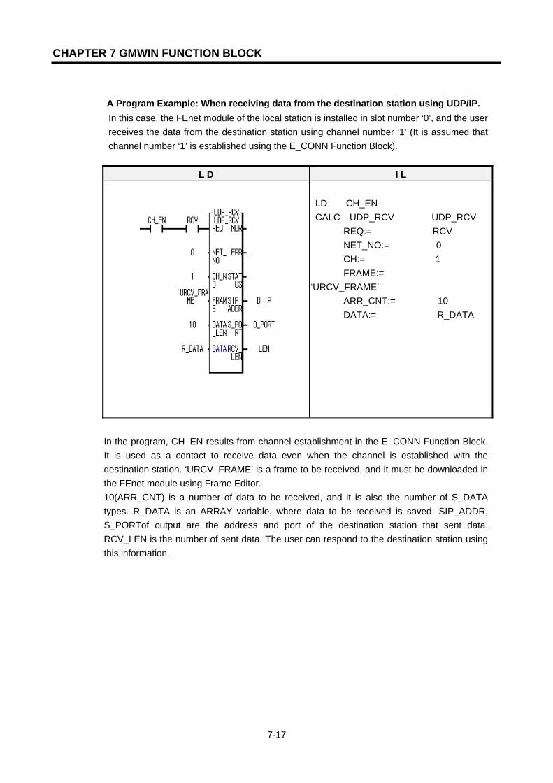
CHAPTER 7 GMWIN FUNCTION BLOCK
7-17
A Program Example: When receiving data from the destination station using UDP/IP.
In this case, the FEnet module of the local station is installed in slot number ‘0’, and the user receives the data from the destination station using channel number ‘1’ (It is assumed that channel number ‘1’ is established using the E_CONN Function Block).
L D I L
LD CH_EN CALC UDP_RCV UDP_RCV REQ:= RCV NET_NO:= 0 CH:= 1 FRAME:= ‘URCV_FRAME’ ARR_CNT:= 10 DATA:= R_DATA
In the program, CH_EN results from channel establishment in the E_CONN Function Block. It is used as a contact to receive data even when the channel is established with the destination station. ‘URCV_FRAME’ is a frame to be received, and it must be downloaded in the FEnet module using Frame Editor. 10(ARR_CNT) is a number of data to be received, and it is also the number of S_DATA types. R_DATA is an ARRAY variable, where data to be received is saved. SIP_ADDR, S_PORTof output are the address and port of the destination station that sent data. RCV_LEN is the number of sent data. The user can respond to the destination station using this information.
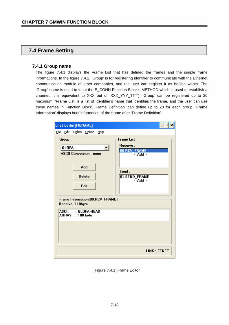
CHAPTER 7 GMWIN FUNCTION BLOCK
7-18
7.4 Frame Setting
7.4.1 Group name The figure 7.4.1 displays the Frame List that has defined the frames and the simple frame informations. In the figure 7.4.2, ‘Group’ is for registering identifier to communicate with the Ethernet communication module of other companies, and the user can register it as he/she wants. The ‘Group’ name is used to input the E_CONN Function Block’s METHOD which is used to establish a channel. It is equivalent to XXX out of ‘XXX_YYY_TTT’). ‘Group’ can be registered up to 20 maximum. ‘Frame List’ is a list of identifier’s name that identifies the frame, and the user can use these names in Function Block. 'Frame Definition’ can define up to 20 for each group. ‘Frame Information’ displays brief information of the frame after ‘Frame Definition’.
[Figure 7.4.1] Frame Editor

CHAPTER 7 GMWIN FUNCTION BLOCK
7-19
[Figure 7.4.2] Group name editor
7.4.2 Frame list The following describes the way how to define the frame.
1) For TX Frame TX Frame: ‘GLOFA-HEAD’+h’ff030200+DATA(100 bytes)
If the communication frame to send between GLOFA FEnet communication modules is like the one above, select (double-click) the ‘Frame List’ on the screen of the [Figure 7.4.1], and then define the frame on the screen of the [Figure 7.4.4].
(1) After setting a frame name in the [Figure 7.4.3], set it as ‘Send’ in ‘TX/RX’. (2) Set segment.
The segment can be set up to 8 maximum. Each segment can be set separately as ‘CONSTANT’, ‘ARRAY’ and ‘SKIP’ respectively.
a) For ‘CONSTANT’, you can set up to 30 bytes maximum using hexadecimal
number, and specify it as ‘ASCII Conversion’. (If ‘ASCII Conversion’ is not set,
the data is used as HEX data).
b) ‘SKIP’ is used when a user wants to skip data of RX frame without checking
them. (only for RX).
c) ‘ARRAY’ displays the data that a user wants to send in Function Block. If you select h’FFFF as size (Unit: Byte) in ‘ARRAY’, it means that data are sent to destination station as much as they are given in Function Block. But, if other value than h’FFFF is selected, it compares data number given from Function Block and size defined in frame. At this time, if it is smaller than that used in the Function Block, an error occurs. Therefore, you should set it the same or larger than that. (See the figure 8.2.1(C)). If you select ‘OK’ after setting according to the order above, frame name is registered in the frame list with the screen closed. The [Figure7.4.4] shows the relation of use between the Function Block and Frame Editor.
If you select ASCII conversion communication,the user can convert the data set to a FunctionBlock by ASCII. Thus, the data transmitted tothe remote station shall be transmitted by anASCII value.
Select ‘binary’ or ‘ASCII’ when doingRX/TX of data.
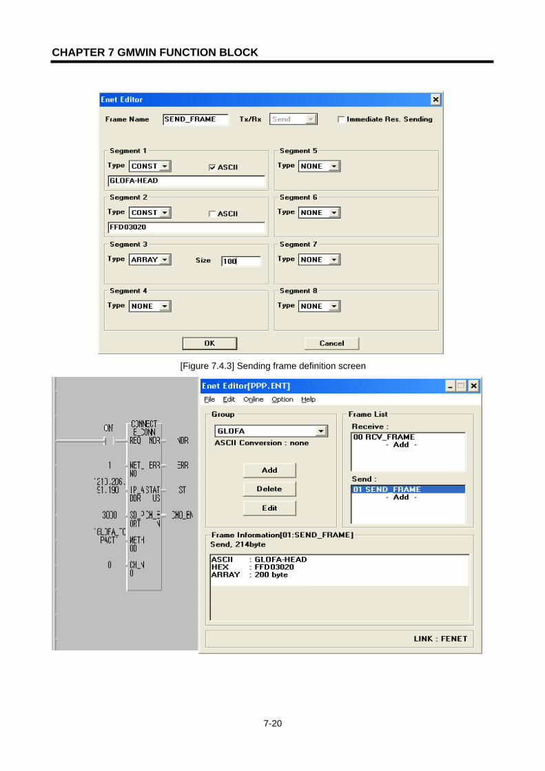
CHAPTER 7 GMWIN FUNCTION BLOCK
7-20
[Figure 7.4.3] Sending frame definition screen
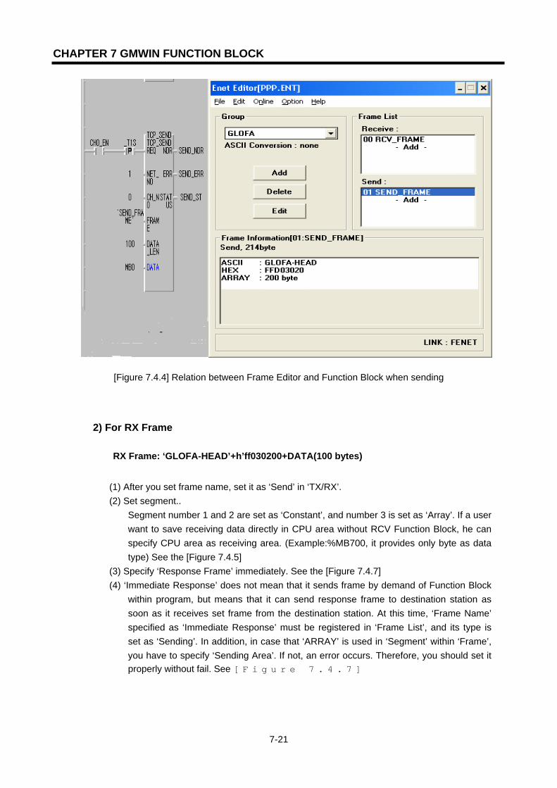
CHAPTER 7 GMWIN FUNCTION BLOCK
7-21
[Figure 7.4.4] Relation between Frame Editor and Function Block when sending
2) For RX Frame
RX Frame: ‘GLOFA-HEAD’+h’ff030200+DATA(100 bytes)
(1) After you set frame name, set it as ‘Send’ in ‘TX/RX’. (2) Set segment..
Segment number 1 and 2 are set as ‘Constant’, and number 3 is set as ‘Array’. If a user want to save receiving data directly in CPU area without RCV Function Block, he can specify CPU area as receiving area. (Example:%MB700, it provides only byte as data type) See the [Figure 7.4.5]
(3) Specify ‘Response Frame’ immediately. See the [Figure 7.4.7] (4) ‘Immediate Response’ does not mean that it sends frame by demand of Function Block
within program, but means that it can send response frame to destination station as soon as it receives set frame from the destination station. At this time, ‘Frame Name’ specified as ‘Immediate Response’ must be registered in ‘Frame List’, and its type is set as ‘Sending’. In addition, in case that ‘ARRAY’ is used in ‘Segment’ within ‘Frame’, you have to specify ‘Sending Area’. If not, an error occurs. Therefore, you should set it properly without fail. See [Figure 7.4.7]
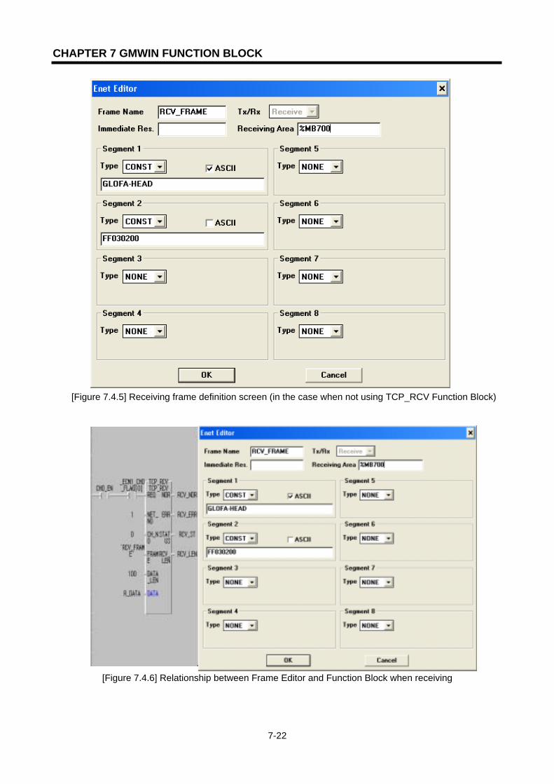
CHAPTER 7 GMWIN FUNCTION BLOCK
7-22
[Figure 7.4.5] Receiving frame definition screen (in the case when not using TCP_RCV Function Block)
[Figure 7.4.6] Relationship between Frame Editor and Function Block when receiving
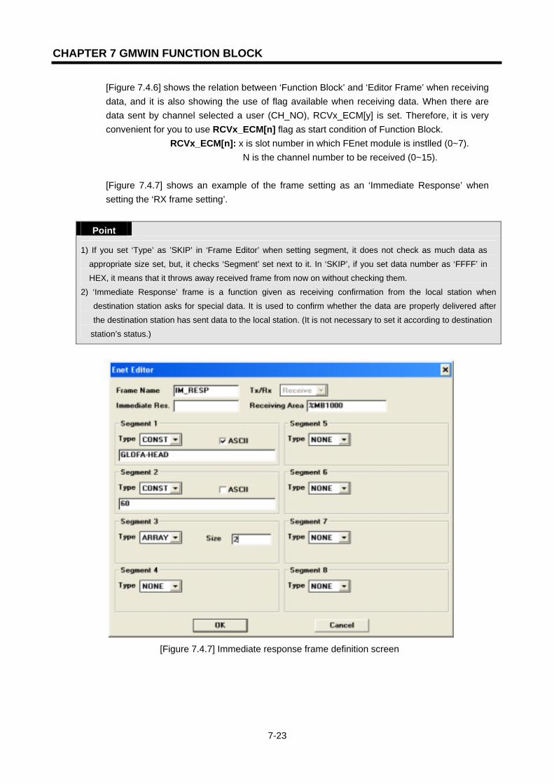
CHAPTER 7 GMWIN FUNCTION BLOCK
7-23
[Figure 7.4.6] shows the relation between ‘Function Block’ and ‘Editor Frame’ when receiving data, and it is also showing the use of flag available when receiving data. When there are data sent by channel selected a user (CH_NO), RCVx_ECM[y] is set. Therefore, it is very convenient for you to use RCVx_ECM[n] flag as start condition of Function Block.
RCVx_ECM[n]: x is slot number in which FEnet module is instlled (0~7). N is the channel number to be received (0~15).
[Figure 7.4.7] shows an example of the frame setting as an ‘Immediate Response’ when setting the ‘RX frame setting’.
Point
1) If you set ‘Type’ as ’SKIP’ in ‘Frame Editor’ when setting segment, it does not check as much data as
appropriate size set, but, it checks ‘Segment’ set next to it. In ‘SKIP’, if you set data number as ‘FFFF’ in
HEX, it means that it throws away received frame from now on without checking them.
2) ‘Immediate Response’ frame is a function given as receiving confirmation from the local station when
destination station asks for special data. It is used to confirm whether the data are properly delivered after
the destination station has sent data to the local station. (It is not necessary to set it according to destination
station’s status.)
[Figure 7.4.7] Immediate response frame definition screen
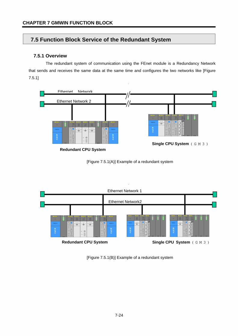
CHAPTER 7 GMWIN FUNCTION BLOCK
7-24
7.5 Function Block Service of the Redundant System 7.5.1 Overview
The redundant system of communication using the FEnet module is a Redundancy Network
that sends and receives the same data at the same time and configures the two networks like [Figure
7.5.1]
[Figure 7.5.1(A)] Example of a redundant system
[Figure 7.5.1(B)] Example of a redundant system
Ethernet Network
Ethernet Network 2
G3Q-RY4ARUN
CPU I/F RUNFB-SERVECEHS-SERVICEGMWIN-SERVICEGLOFA-SERVICEFTP-SERVICEH/W-ERROR
10BASE5 ENABLE
10BASE2 ENABLE10BASE-T LINK10BASE-T PLRTYTXRX
L00
01
02
03
04
05
06
07
COM
L16
17
18
19
04
21
22
23
COM
08L09
10
11
1213
14
15
COM
08L 25
26
27
2829
30
31
COM
+- DC24V
RELAYAC250V 2ADC24V 2A
PROGRAMMABLECONTROLLER
GLO
FA
GM3-PA1A
PWR
G3L-EUEA
RUNCPU I/F RUNFB-SERVECEHS-SERVICEGMWIN-SERVICEGLOFA-SERVICEFTP-SERVICEH/W-ERROR
10BASE5 ENABLE10BASE2 ENABLE10BASE-T LINK10BASE-T PLRTYTXRX
MODE
1
234
5
06
7 8 9
0: ON.RUN1: TEST12: TEST2
EXT.POWER
DC IN
+12V
12G
FG
10BASE5
10BASE2
10BASE-T
RUN
GM1-CPUA
RUNSTOP
REMOTEFAIL
ERROR
PAU/REM
STOP
G3L-EUEA
RUNCPU I/F RUNFB-SERVECEHS-SERVICEGMWIN-SERVICEGLOFA-SERVICEFTP-SERVICEH/W-ERROR
10BASE5 ENABLE10BASE2 ENABLE10BASE-T LINK10BASE-T PLRTYTXRX
MODE
1234
5
06
7 8 9
0: ON.RUN1: TEST1
2: TEST2
EXT.POWER
DC IN
+12V
12G
FG
10BASE5
10BASE2
10BASE-T
Redundant CPU System Single CPU System (GM3)
PROGRAMMABLECONTROLLER
GLO
FA
GM3-PA1A
PWR
G3L-EUEARUNCPU I/F RUNFB-SERVECEHS-SERVICEGMWIN-SERVICEGLOFA-SERVICEFTP-SERVICEH/W-ERROR
10BASE5 ENABLE10BASE2 ENABLE10BASE-T LINK10BASE-T PLRTYTXRX
MODE
1
234
5
06
7 8 9
0: ON.RUN1: TEST12: TEST2
EXT.POWER
DC IN
+12V
12G
FG
10BASE5
10BASE2
10BASE-T
RUN
GM1-CPUA
RUNSTOP
REMOTEFAIL
ERROR
PAU/REM
STOP A
GM1-DIFA
A SELA+B
B AELCPU-ACPU-B
A+B
B
EXTPWR
RS232C
RUN
GM1-CPUA
RUNSTOP
REMOTEFAIL
ERROR
PAU/REM
STOP
G3L-EUEA
RUNCPU I/F RUNFB-SERVECEHS-SERVICEGMWIN-SERVICEGLOFA-SERVICEFTP-SERVICEH/W-ERROR
10BASE5 ENABLE10BASE2 ENABLE10BASE-T LINK10BASE-T PLRTYTXRX
MODE
1
234
5
06
7 8 9
0: ON.RUN1: TEST12: TEST2
EXT.POWER
DC IN
+12V
12G
FG
10BASE5
10BASE2
10BASE-T
PROGRAMMABLECONTROLLER
GLO
FA
GM3-PA1A
PWR
Ethernet Network 1
Ethernet Network2
Redundant CPU System ( )
Single CPU System (GM3)
G3Q-RY4ARUNCPU I/F RUNFB-SERVECEHS-SERVICEGMWIN-SERVICEGLOFA-SERVICEFTP-SERVICEH/W-ERROR
10BASE5 ENABLE10BASE2 ENABLE10BASE-T LINK10BASE-T PLRTYTXRX
L00
01
0203
04
05
06
07
COM
L 16
17
1819
04
21
22
23
COM
08L 09
1011
1213
14
15
COM
08L25
2627
2829
3031
COM
+- DC24V
RELAYAC250V 2ADC24V 2A
PROGRAMMABLECONTROLLER
GLO
FA
GM3-PA1A
PWR
G3L-EUEA
RUNCPU I/F RUNFB-SERVECEHS-SERVICEGMWIN-SERVICEGLOFA-SERVICEFTP-SERVICEH/W-ERROR
10BASE5 ENABLE10BASE2 ENABLE10BASE-T LINK10BASE-T PLRTYTXRX
MODE
1
2345
06
7 8 9
0: ON.RUN1: TEST12: TEST2
EXT.POWER
DC IN
+12V
12G
FG
10BASE5
10BASE2
10BASE-T
RUN
GM1-CPUA
RUNSTOP
REMOTEFAIL
ERROR
PAU/REM
STOP
G3Q-RY4ARUNCPU I/F RUNFB-SERVECEHS-SERVICEGMWIN-SERVICEGLOFA-SERVICEFTP-SERVICEH/W-ERROR
10BASE5 ENABLE10BASE2 ENABLE10BASE-T LINK10BASE-T PLRTYTXRX
L00
01
0203
04
05
06
07
COM
L 16
17
1819
04
21
22
23
COM
08L 09
1011
1213
14
15
COM
08L25
2627
2829
3031
COM
+- DC24V
RELAYAC250V 2ADC24V 2A
PROGRAMMABLECONTROLLER
GLO
FA
GM3-PA1A
PWR
G3L-EUEA
RUNCPU I/F RUNFB-SERVECEHS-SERVICEGMWIN-SERVICEGLOFA-SERVICEFTP-SERVICEH/W-ERROR
10BASE5 ENABLE10BASE2 ENABLE10BASE-T LINK10BASE-T PLRTYTXRX
MODE
1
2345
06
7 8 9
0: ON.RUN1: TEST12: TEST2
EXT.POWER
DC IN
+12V
12G
FG
10BASE5
10BASE2
10BASE-T
RUN
GM1-CPUA
RUNSTOP
REMOTEFAIL
ERROR
PAU/REM
STOPPROGRAMMABLECONTROLLER
GLO
FA
GM3-PA1A
PWR
G3L-EUEA
RUNCPU I/F RUNFB-SERVECEHS-SERVICEGMWIN-SERVICEGLOFA-SERVICEFTP-SERVICEH/W-ERROR
10BASE5 ENABLE10BASE2 ENABLE10BASE-T LINK10BASE-T PLRTYTXRX
MODE
1
234
5
06
7 8 9
0: ON.RUN1: TEST12: TEST2
EXT.POWER
DC IN
+12V
12G
FG
10BASE5
10BASE2
10BASE-T
RUN
GM1-CPUA
RUNSTOP
REMOTEFAIL
ERROR
PAU/REM
STOP A
GM1-DIFA
A SELA+B
B AELCPU-ACPU-B
A+B
B
EXTPWR
RS232C
RUN
GM1-CPUA
RUNSTOP
REMOTEFAIL
ERROR
PAU/REM
STOP
G3L-EUEA
RUNCPU I/F RUNFB-SERVECEHS-SERVICEGMWIN-SERVICE
GLOFA-SERVICEFTP-SERVICEH/W-ERROR
10BASE5 ENABLE10BASE2 ENABLE10BASE-T LINK10BASE-T PLRTYTXRX
MODE
1
234
5
06
7 8 9
0: ON.RUN1: TEST1
2: TEST2
EXT.POWER
DC IN
+12V
12G
FG
10BASE5
10BASE2
10BASE-T
PROGRAMMABLECONTROLLER
GLO
FA
GM3-PA1A
PWR

CHAPTER 7 GMWIN FUNCTION BLOCK
7-25
[Figure 7.5.2] Example of a redundant system
7.5.2 Characteristics of redundant Function Blocks
If the Function Block is used in a redundant system, it has the following characteristics compared with the existing Function Block.
- In a redundant Function Block, 2 Function Blocks perform their services with different communication paths at the same time. Therefore, if one side is not in service, the other side is continuing to do the service.
- Basic I/O data is identical to the existing Function Block. - If only one of the two paths succeeds in its service, it still output normal data. - The time of a redundant Function Block is a bit longer than the existing Function Block for
data processing. - The TX/RX size of the dual system is different from that of the single system. (See below)
Total Data Size GMR CPU GM1/2/3/4 READ 1024 Bytes 1400 Bytes WRITE 400 Bytes 1400 Bytes
HS_LINK 120 Bytes 400 Bytes
IP:210.206.91.190 IP:210.206.91.191 IP:210.206.90.190 IP:210.206.90.191
Upper System
IP: 210.206.91.189
IP: 210.206.90.189
Upper System
IP: 210.206.91.189
IP: 210.206.90.189
PC PC
HUB HUB
B Side
IP:210.206.0.188 A Side
IP:210.206.91.188

CHAPTER 7 GMWIN FUNCTION BLOCK
7-26
- The library used when implementing the redundant system is as follows.
(The name of the redundant Function Block is Dxxx. The existing Function Block is xxx.)
Classification GMR CPU GM1/2 CPU GM3 CPU GM4 CPU GM4 CPU
Single System -- COMMUNI.
1FB COMMUNI.
3FB COMMUNI.
2FB COMMUNI.
4FB COMMUNI.
RFB COMMUNI.1
FB COMMUNI.3
FB COMMUNI.
2FB COMMUNI.4
FB Redundant System
-- DUAL_FB.
1FB DUAL_FB.
3FB DUAL_FB.
2FB DUAL_FB.
4FB [Table 7.5.1] Library of redundant Function Block
DUAL_FB.xFB is the user library using the existing Function Block edited for redundancy.
7.5.3 Types of redundant Function Blocks
The redundant Function Block used to edit a program in a redundant system is as follows. Its function, type and usage are the same as the content written in chapter 7.2.
Types Uses
DE_CONN When the logical communication channel is established with the destination station.
DTCP_SEND Sends data from the local station using TCP/IP to the destination station..
DTCP_RCV Receives data from destination station using TCP/IP.
DUDP_SEND Sends data from the local station using UDP/IP to the destination station.
DUDP_RCV Receives data from the destination station using UDP/IP.
[Table 7.5.2] The types of the redundant Function Blocks
7.5.4 Action of the redundant Function Block
GMR CPU A
FEnet A FEnet A
Dual FB GM1/2/3/4 CPU Dual FB
FEnet B FEnet B
GMR CPU B
[Figure 7.5.4] Execution Diagram for Redundant Function Block Service

CHAPTER 7 GMWIN FUNCTION BLOCK
7-27
In [Figure 7.5.4] two FEnet modules are executing the same communication at the same time. In the user program, the modules implement it only with the dual Function Block.
The following describes characteristics of the common I/O of each Function Block. Input
NET_NO: It specifies the slot number that the communication module is installed. For slot position, slot number ‘0’ is next to CPU, and it increases ‘1’ by ‘1’ and the setting range is from 0 to 7. In the case of GM1/2/3/4 in the following figure, the slot number of the left module out of two FEnet modules is specified. (Two communication modules must be installed close to each other.)
0 1 2 3 0 1 2 3 0 1 2 3 4
IP_ADDR, D_PORT, S_PORT, CH_NO:
If the Function Block is input for one of two FEnet modules, both modules are applied at the same time.
Output
The output shows the result for one of the two modules, in which its service is normally performed ahead. If both are acting abnormally, it shows its result in ERR, STATUS. Basic operation is identical to the content in chapter 7.2.
G3Q-RY4ARUNCPU I/F RUNFB-SERVECEHS-SERVICEGMWIN-SERVICEGLOFA-SERVICEFTP-SERVICEH/W-ERROR
10BASE5 ENABLE10BASE2 ENABLE10BASE-T LINK10BASE-T PLRTYTXRX
L 00
01
0203
04
05
06
07
COM
L 16
17
18
19
04
21
22
23
COM
08L 09
1011
1213
14
15
COM
08L 25
26
27
2829
30
31COM
+- DC24V
RELAYAC250V 2ADC24V 2A
PROGRAMMABLECONTROLLER
GLO
FA
GM3-PA1A
PWR
G3L-EUEARUNCPU I/F RUNFB-SERVECEHS-SERVICEGMWIN-SERVICEGLOFA-SERVICEFTP-SERVICEH/W-ERROR
10BASE5 ENABLE10BASE2 ENABLE10BASE-T LINK10BASE-T PLRTYTXRX
MODE
1
2345
06
7 8 9
0: ON.RUN1: TEST12: TEST2
EXT.POWER
DC IN
+12V
12G
FG
10BASE5
10BASE2
10BASE-T
RUN
GM1-CPUA
RUNSTOP
REMOTEFAIL
ERROR
PAU/REM
STOP
G3L-EUEARUN/BPSTX/BPSRS/BPSACK/DATA-BITNAK/PARITYERR/EVEN-ODDNODEM/STOP-BITSYS-RUN
MODE
RS-232C
1
2345
06
7 8 9
DISPLAY
RS-422
RDA
RDB
SDA
SDB
SG
FG
RUN/BPSTX/BPSRX/BPSACK/DATA-BITNAK/PARITYERR/EVEN-ODDRS-485/STOP-BITSYS-ERROR
RS-232C
RS-422
G3L-EUEA
RUNCPU I/F RUNFB-SERVECEHS-SERVICEGMWIN-SERVICEGLOFA-SERVICEFTP-SERVICEH/W-ERROR
10BASE5 ENABLE10BASE2 ENABLE10BASE-T LINK10BASE-T PLRTYTXRX
MODE
12345
06
7 8 9
0: ON.RUN1: TEST12: TEST2
EXT.POWER
DC IN
+12V
12G
FG
10BASE5
10BASE2
10BASE-T
RUN
GM1-CPUA
RUNSTOP
REMOTEFAIL
ERROR
PAU/REM
STOP A
GM1-DIFA
A SELA+B
B AELCPU-ACPU-B
A+B
B
EXTPWR
RS232C
RUN
GM1-CPUA
RUNSTOP
REMOTEFAIL
ERROR
PAU/REM
STOP
PROGRAMMABLECONTROLLER
GLO
FA
GM3-PA1A
PWR
G3L-EUEARUN/BPSTX/BPSRS/BPSACK/DATA-BITNAK/PARITYERR/EVEN-ODDNODEM/STOP-BITSYS-RUN
MODE
RS-232C
1
2345
06
7 8 9
DISPLAY
RS-422
RDA
RDB
SDA
SDB
SG
FG
RUN/BPSTX/BPSRX/BPSACK/DATA-BITNAK/PARITYERR/EVEN-ODDRS-485/STOP-BITSYS-ERROR
RS-232C
RS-422
G3L-EUEARUN/BPSTX/BPSRS/BPSACK/DATA-BITNAK/PARITYERR/EVEN-ODDNODEM/STOP-BITSYS-RUN
MODE
RS-232C
1
2345
06
7 89
DISPLAY
RS-422
RDA
RDB
SDA
SDB
SG
FG
RUN/BPSTX/BPSRX/BPSACK/DATA-BITNAK/PARITYERR/EVEN-ODDRS-485/STOP-BITSYS-ERROR
RS-232C
RS-422
G3L-EUEA
RUNCPU I/F RUNFB-SERVECEHS-SERVICEGMWIN-SERVICEGLOFA-SERVICEFTP-SERVICEH/W-ERROR
10BASE5 ENABLE10BASE2 ENABLE10BASE-T LINK10BASE-T PLRTYTXRX
MODE
1
234
5
06
7 8 9
0: ON.RUN1: TEST12: TEST2
EXT.POWER
DC IN
+12V
12G
FG
10BASE5
10BASE2
10BASE-T
PROGRAMMABLECONTROLLER
GLO
FA
GM3-PA1A
PWR
G3L-EUEARUN/BPSTX/BPSRS/BPSACK/DATA-BITNAK/PARITYERR/EVEN-ODDNODEM/STOP-BITSYS-RUN
MODE
RS-232C
1
234
5 06
7 8 9
DISPLAY
RS-422
RDA
RDB
SDA
SDB
SG
FG
RUN/BPSTX/BPSRX/BPSACK/DATA-BITNAK/PARITYERR/EVEN-ODDRS-485/STOP-BITSYS-ERROR
RS-232C
RS-422
G3L-EUEARUN/BPSTX/BPSRS/BPSACK/DATA-BITNAK/PARITYERR/EVEN-ODDNODEM/STOP-BITSYS-RUN
MODE
RS-232C
1
234506
7 8 9
DISPLAY
RS-422
RDA
RDB
SDA
SDB
SG
FG
RUN/BPSTX/BPSRX/BPSACK/DATA-BITNAK/PARITYERR/EVEN-ODDRS-485/STOP-BITSYS-ERROR
RS-232C
RS-422
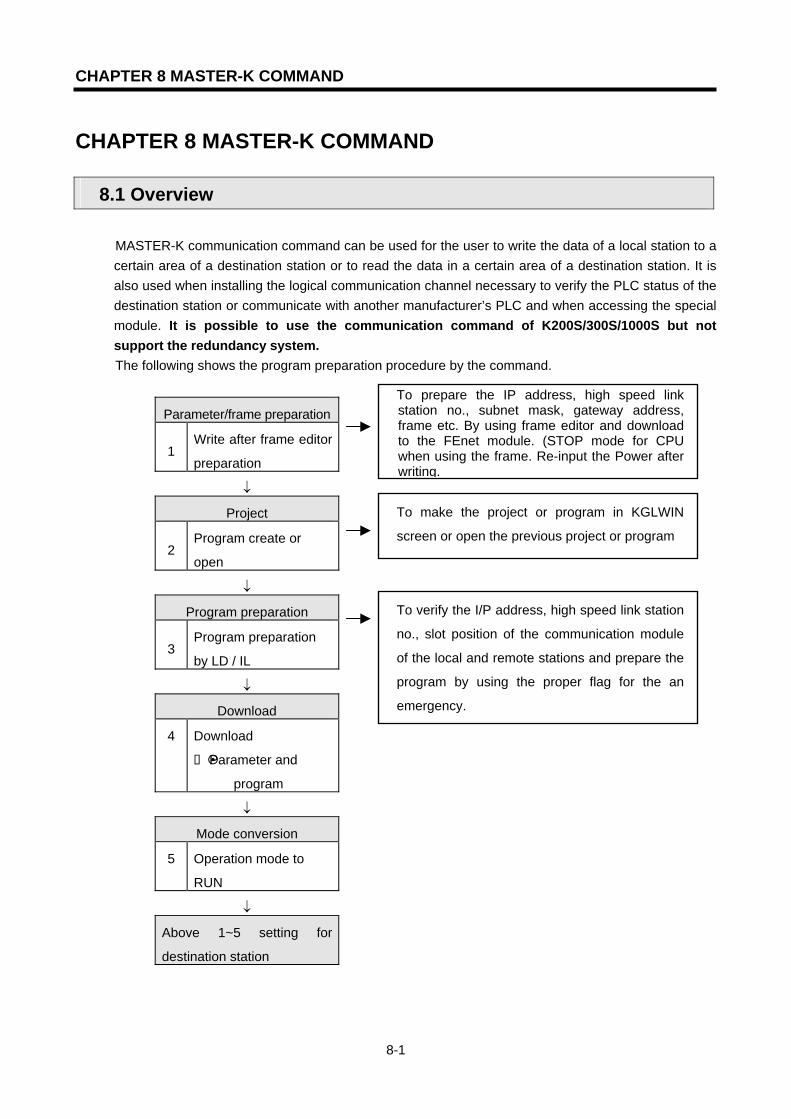
CHAPTER 8 MASTER-K COMMAND
8-1
CHAPTER 8 MASTER-K COMMAND
8.1 Overview
MASTER-K communication command can be used for the user to write the data of a local station to a certain area of a destination station or to read the data in a certain area of a destination station. It is also used when installing the logical communication channel necessary to verify the PLC status of the destination station or communicate with another manufacturer’s PLC and when accessing the special module. It is possible to use the communication command of K200S/300S/1000S but not support the redundancy system. The following shows the program preparation procedure by the command.
Parameter/frame preparation
1 Write after frame editor
preparation
↓
Project
2 Program create or
open
↓
Program preparation
3 Program preparation
by LD / IL
↓
Download
4 Download
Parameter and
program
↓
Mode conversion
5 Operation mode to
RUN
↓
Above 1~5 setting for
destination station
To prepare the IP address, high speed link station no., subnet mask, gateway address, frame etc. By using frame editor and download to the FEnet module. (STOP mode for CPU when using the frame. Re-input the Power after writing.
To make the project or program in KGLWIN
screen or open the previous project or program
To verify the I/P address, high speed link station
no., slot position of the communication module
of the local and remote stations and prepare the
program by using the proper flag for the an
emergency.
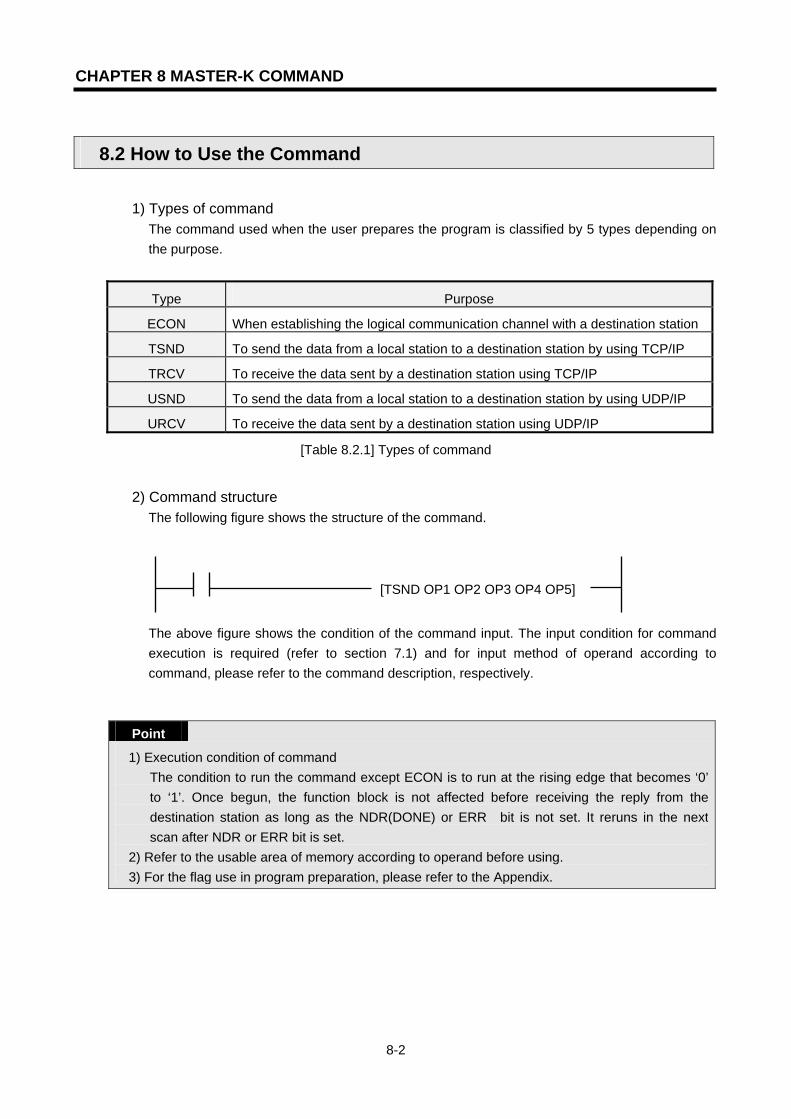
CHAPTER 8 MASTER-K COMMAND
8-2
8.2 How to Use the Command
1) Types of command
The command used when the user prepares the program is classified by 5 types depending on the purpose.
Type Purpose
ECON When establishing the logical communication channel with a destination station
TSND To send the data from a local station to a destination station by using TCP/IP
TRCV To receive the data sent by a destination station using TCP/IP
USND To send the data from a local station to a destination station by using UDP/IP
URCV To receive the data sent by a destination station using UDP/IP
[Table 8.2.1] Types of command
2) Command structure The following figure shows the structure of the command.
[TSND OP1 OP2 OP3 OP4 OP5]
The above figure shows the condition of the command input. The input condition for command execution is required (refer to section 7.1) and for input method of operand according to command, please refer to the command description, respectively.
Point
1) Execution condition of command The condition to run the command except ECON is to run at the rising edge that becomes ‘0’ to ‘1’. Once begun, the function block is not affected before receiving the reply from the destination station as long as the NDR(DONE) or ERR bit is not set. It reruns in the next scan after NDR or ERR bit is set.
2) Refer to the usable area of memory according to operand before using. 3) For the flag use in program preparation, please refer to the Appendix.

CHAPTER 8 MASTER-K COMMAND
8-3
8.3 Types of Command
8.3.1 ECON
Model K1000S K300S K200S K80S K120S
Application n n n
Available device FLAG
OPERLAN
D M P K L F T C D #D
CON
STA
NT
STEPERROR
(F110)
ZERO
(F111)
CARRY
(F112) RMKS
OP1
OP2
OP3
OP4
0
(AREA
OVER)
[ECON OP1 OP2 OP3 OP4] OPERLAND DESCRIPTION
OP1 Device 0: CH_NO(high byte),
SLOT_NO(low byte) Device 1: PORT_NO(word)
CH_NO: The channel no. to establish (0~15) SLOT_NO: The slot no. where the communication
module is installed PORT_NO: The port No. when establishing the channel
OP2 Device 0-3: IP_ADDR
(ex. 192.168.100.1) ->Device0=192, Device1=168)
IP_ADDR: When the channel is established by TCP_ACTIVE, the IP address of the destination station is used. When the channel is established by TCP_PASSIVE, the IP address of the destination station is used.
OP3 Device 0-7: METHOD (ASCII Data, within 16byte)
METHOD: To determine whether to act by TCP or UDP, Client or Server when established channel (refer to the description below)
OP4 Device 0: STATUS(high byte),
ERR(1'bit), NDR(0'bit) Device 1: CH_EN(0'bit)
NDR: ON when normal channel establishment ERR: ON when an error occurs after command execution STATUS: Detail code value for the error CH_EN: Result for channel establishment
1) TCP_ACTIVE: Destination station port (Dest Port) + destination station IP address (Dest IP_ADDR) This is the channel to use TCP/IP and designates the destination station for communication. For communication with the designated destination station, the local station acts as the client.
2) TCP_PASSIVE: local station port (Source Port) + local station IP address (Source IP_ADDR)
This is the channel to use TCP/IP, which is established for the station that requires to establish the channel first. The local station acts as the server for communication with the designated destination station.
Logical communication channel
establishment with the remote station

CHAPTER 8 MASTER-K COMMAND
8-4
3) TCP_SELECT: local station port (Source Port) + destination station IP address (Dest IP_ADDR)
This is a kind of TCP_PASSIVE and establishes the channel only for the destination station designated by the user. The local station acts as the server for communication with the designated destination station.
4) UDP_ACTIVE: local station port (Source Port) + local station IP address (Source IP_ADDR) This is the channel to use UDP/IP and opens only a socket. For the communication with the designated destination station, the local station acts as client. (Actually, the channel is not bound.)
5) UDP_PASSIVE: local station port (Source Port) + local station IP address (Source IP_ADDR)
This is the channel to use UDP/IP and only a socket is bound. For communication with the designated destination station, the local station acts as the server. (Actually, the channel is not bound.)
Point
1) PASSIVE (SELECT) OPEN should start prior to ACTIVE OPEN. UDP_ACTIVE, UDP_PASSIVE does not establish the channel by the service and opens the socket only to connect internally.
As above, the user should establish the channel suitable for communication characteristics according to the type of logical channel establishment. The request for channel establishment shall be established based on the value of METHOD among operand input.
METHOD: ‘XXX_YYY(or ‘XXX_YYY_TTT’) - (less than 16digits: string)
XXX: group name prepared by frame editor. YYY: channel establishment type (TCPACT, TCPPAS, TCPSEL, UDPACT,
UDPPAS: 5 types) TTT: sending/receiving standby time for channel release (0~FF sec.). If there is
no response from the opposite side within a certain setting time, disconnect the connection by force. (for TCPPAS)

CHAPTER 8 MASTER-K COMMAND
8-5
8.3.2 TSND
Model K1000S K300S K200S K80S K120S
Application n n n
AVAILABLE DEVICE FLAG
OPERLAN
D M P K L F T C D #D
CON
STA
NT
STEPERRO
R
(F110)
ZERO
(F111)
CARRY
(F112)
REM
ARKS
OP1
OP2
OP3
OP4
OP5
0
(AREA
OVER)
[TSND OP1 OP2 OP3 OP4 OP5] OPERLAND DESCRIPTION
OP1 Device 0: CH_NO(high byte),
SLOT_NO(low byte)
CH_NO: The channel no. established by the ECON
command
SLOT_NO: The slot no. where the communication
module is installed.
OP2 Device 0-7: FRAME FRAME: Frame desired to send
Uses the name as it is used in frame editor
OP3 Device 0: SND_AREA Area where the sending data is saved
OP4 LENGTH Data size desired to send
OP5 Device 0: STATUS(high byte),
ERR(1'bit), NDR(0'bit)
NDR: ON when the channel is established normally
ERR: ON when an error occurs after a command
execution
STATUS: Detailed code value for the error
This is used to send the data of the local station to the destination station by using TCP/IP.
ACTION is done by reading the data as much as ‘LENGTH’ from ‘SND_AREA’ and sending the
data to the destination station established by the CH_NO’ channel in the designated format in
‘FRAME’. The entered name in ‘FRAME’ should be used by the name defined by the
sending/receiving format in the frame editor. If the service runs normally, the NDR bit shall be
‘On’. If an error occurs, ERR will be turned on and the code value accordingly shall saved in
STATUS.
When sending the data to a remote
station by using TCP/IP
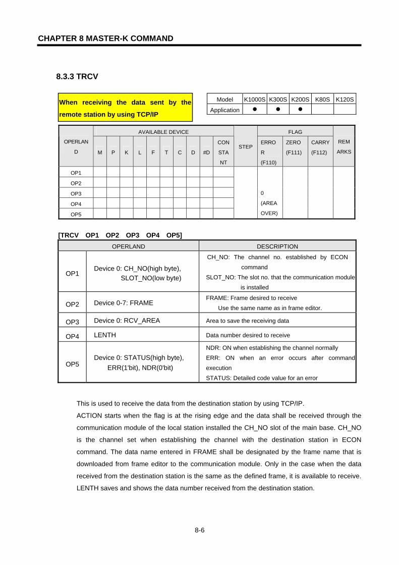
CHAPTER 8 MASTER-K COMMAND
8-6
8.3.3 TRCV
Model K1000S K300S K200S K80S K120S
Application n n n
AVAILABLE DEVICE FLAG
OPERLAN
D M P K L F T C D #D
CON
STA
NT
STEPERRO
R
(F110)
ZERO
(F111)
CARRY
(F112)
REM
ARKS
OP1
OP2
OP3
OP4
OP5
0
(AREA
OVER)
[TRCV OP1 OP2 OP3 OP4 OP5] OPERLAND DESCRIPTION
OP1 Device 0: CH_NO(high byte),
SLOT_NO(low byte)
CH_NO: The channel no. established by ECON
command
SLOT_NO: The slot no. that the communication module
is installed
OP2 Device 0-7: FRAME FRAME: Frame desired to receive
Use the same name as in frame editor.
OP3 Device 0: RCV_AREA Area to save the receiving data
OP4 LENTH Data number desired to receive
OP5 Device 0: STATUS(high byte),
ERR(1'bit), NDR(0'bit)
NDR: ON when establishing the channel normally
ERR: ON when an error occurs after command
execution
STATUS: Detailed code value for an error
This is used to receive the data from the destination station by using TCP/IP.
ACTION starts when the flag is at the rising edge and the data shall be received through the
communication module of the local station installed the CH_NO slot of the main base. CH_NO
is the channel set when establishing the channel with the destination station in ECON
command. The data name entered in FRAME shall be designated by the frame name that is
downloaded from frame editor to the communication module. Only in the case when the data
received from the destination station is the same as the defined frame, it is available to receive.
LENTH saves and shows the data number received from the destination station.
When receiving the data sent by the
remote station by using TCP/IP
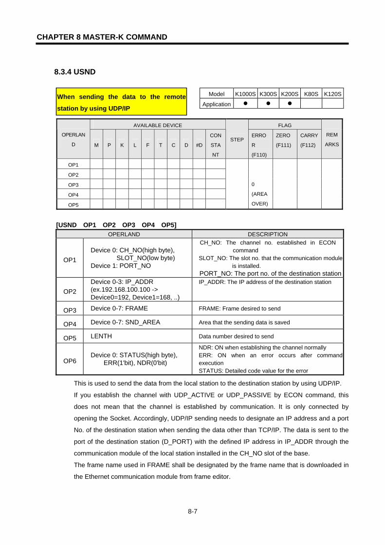
CHAPTER 8 MASTER-K COMMAND
8-7
8.3.4 USND
Model K1000S K300S K200S K80S K120S
Application n n n
AVAILABLE DEVICE FLAG
OPERLAN
D M P K L F T C D #D
CON
STA
NT
STEPERRO
R
(F110)
ZERO
(F111)
CARRY
(F112)
REM
ARKS
OP1
OP2
OP3
OP4
OP5
0
(AREA
OVER)
[USND OP1 OP2 OP3 OP4 OP5] OPERLAND DESCRIPTION
OP1 Device 0: CH_NO(high byte),
SLOT_NO(low byte) Device 1: PORT_NO
CH_NO: The channel no. established in ECON command
SLOT_NO: The slot no. that the communication module is installed.
PORT_NO: The port no. of the destination station
OP2 Device 0-3: IP_ADDR (ex.192.168.100.100 -> Device0=192, Device1=168, ..)
IP_ADDR: The IP address of the destination station
OP3 Device 0-7: FRAME FRAME: Frame desired to send
OP4 Device 0-7: SND_AREA Area that the sending data is saved
OP5 LENTH Data number desired to send
OP6 Device 0: STATUS(high byte),
ERR(1'bit), NDR(0'bit)
NDR: ON when establishing the channel normally ERR: ON when an error occurs after command
execution STATUS: Detailed code value for the error
This is used to send the data from the local station to the destination station by using UDP/IP.
If you establish the channel with UDP_ACTIVE or UDP_PASSIVE by ECON command, this
does not mean that the channel is established by communication. It is only connected by
opening the Socket. Accordingly, UDP/IP sending needs to designate an IP address and a port
No. of the destination station when sending the data other than TCP/IP. The data is sent to the
port of the destination station (D_PORT) with the defined IP address in IP_ADDR through the
communication module of the local station installed in the CH_NO slot of the base.
The frame name used in FRAME shall be designated by the frame name that is downloaded in
the Ethernet communication module from frame editor.
When sending the data to the remote
station by using UDP/IP

CHAPTER 8 MASTER-K COMMAND
8-8
8.3.5 URCV
Model K1000S K300S K200S K80S K120S
Application n n n
AVAILABLE DEVICE FLAG
OPERLAN
D M P K L F T C D #D
CON
STA
NT
STEPERRO
R
(F110)
ZERO
(F111)
CARRY
(F112)
REM
ARKS
OP1
OP2
OP3
OP4
OP5
0
(AREA
OVER)
[URCV OP1 OP2 OP3 OP4 OP5] OPERLAND DESCRIPTION
OP1 Device 0: CH_NO(high byte),
SLOT_NO(low byte)
CH_NO: The channel no. established in ECON
command
SLOT_NO: The slot no. that the communication
module is installed.
OP2 Device 0-7: FRAME FRAME: Frame desired to receive
OP3 Device 0: RCV_AREA Area that receiving data is saved
OP4 LENTH Data number desired to receive
OP5
Device 0: STATUS(high byte), ERR(1'bit), NDR(0'bit)
Device 1: PORT Device 2: RCV_LEN Device 3-6: IP_ADDR
NDR: ON when normal service starts
ERR: ON when an error occurs after command
execution
STATUS: Detailed code value for an error
PORT: The port of the data sending station
RCV_LEN: Receiving data size
IP_ADDR: The IP address of the data sending station
This is used to receive the data of the destination station by using UDP/IP.
As UDP/IP communication does not establish the channel. It is available to receive all data
which is sending to the port no. open to the local station. Accordingly, URCV command can
determined which station (SIP_ADDR) sent the data to which port no. (S_PORT) other than
TRCV.
When receiving the data sent by a remote
station by using UDP/IP.

CHAPTER 9 REMOTE COMMUNICATION CONTROL
9-1
CHAPTER 9 REMOTE COMMUNICATION CONTROL
9.1 Overview
This is the function to control remote the program preparation, the user program download, program debugging, monitor etc. in the network system that PLC is connected each other by Ethernet, without moving the physical connection of GMWIN/KGLWIN. Especially, in case that the devices connected to the network are far apart, this is very convenient function to access easily each device from one place without moving the place. GMWIN/KGLWIN remote communication service function enables to accomplish the purpose by generating the Logical Path as follows:
[Figure 9.1.1] Dedicated network for Ethernet [Figure 9.1.1] shows the assumption of the network that in GMWIN/KGLWIN, RS-232C cable is connected to PLC #1 station and PLC #1, PLC #2 and PLC #N are connected each other by Ethernet. In order to access the content of PLC station #1 on the above, do the local connection from online menu of GMWIN/KGLWIN. In order to access the content of PLC #N station after completion of access, disconnect the connection of PLC #1 station by using ‘disconnect’ menu. And then if you select PLC #N(station no.: N, PLC #1 FEnet slot: 2) from Remote Connection of online menu, the logical connection by RS-232C and Ethernet will be completed. This status is regarded as same as if it is connected by moving RS-232C cable to PLC #N station, which enables to do all function available in PLC #1 such as program preparation, download, debugging and monitor etc. And if Ethernet module is installed in the PC that GMWIN/KGLWIN is active, and is connected to the same network with PLC, the Remote Connection step 1 with PLC through Ethernet available without local connection through RS-232C. If the user uses GMWIN/KGLWIN remote communication service, it is available to connect easily without moving to far apart PLC as well as to solve the difficulty of reprogramming after installation as it enables to connect from other PLC even if PLC is located in the place difficult to access in space.
Desktop System
G3Q-RY4ARUNCPU I/F RUNFB-SERVECEHS-SERVICEGMWIN-SERVICEGLOFA-SERVICEFTP-SERVICEH/W-ERROR
10BASE5 ENABLE10BASE2 ENABLE10BASE-T LINK10BASE-T PLRTYTXRX
L00
01
02
03
04
05
06
07
COM
L16
17
18
19
04
21
22
23
COM
08L 09
1011
1213
14
15
COM
08L 25
2627
28
29
30
31COM
+- DC24V
RELAYAC250V 2ADC24V 2A
PROGRAMMABLECONTROLLER
GLO
FA
GM3-PA1A
PWR
G3L-EUEARUNCPU I/F RUNFB-SERVECEHS-SERVICEGMWIN-SERVICEGLOFA-SERVICEFTP-SERVICEH/W-ERROR
10BASE5 ENABLE10BASE2 ENABLE10BASE-T LINK10BASE-T PLRTYTXRX
MODE
1
2345
06
7 8 9
0: ON.RUN1: TEST12: TEST2
EXT.POWER
DC IN
+12V
12G
FG
10BASE5
10BASE2
10BASE-T
RUN
GM1-CPUA
RUNSTOP
REMOTEFAIL
ERROR
PAU/REM
STOP
G3L-FUEA
MODE
0: ON.RUN1: TEST12: TEST2
X1
X10
CON1
CON2
1234
5
06
7 89
1
234
5
06
7 89
1
2345
06
7 89
RUN
LAS
TOKEN
TX/RX
FAULT
G3Q-RY4ARUNCPU I/F RUNFB-SERVECEHS-SERVICEGMWIN-SERVICEGLOFA-SERVICEFTP-SERVICEH/W-ERROR
10BASE5 ENABLE10BASE2 ENABLE10BASE-T LINK10BASE-T PLRTYTXRX
L00
01
02
03
04
05
06
07
COM
L16
17
18
19
04
21
22
23
COM
08L 09
1011
1213
14
15
COM
08L 25
2627
28
29
30
31COM
+- DC24V
RELAYAC250V 2ADC24V 2A
PROGRAMMABLECONTROLLER
GLO
FA
GM3-PA1A
PWR
G3L-EUEARUNCPU I/F RUNFB-SERVECEHS-SERVICEGMWIN-SERVICEGLOFA-SERVICEFTP-SERVICEH/W-ERROR
10BASE5 ENABLE10BASE2 ENABLE10BASE-T LINK10BASE-T PLRTYTXRX
MODE
1
2345
06
7 89
0: ON.RUN1: TEST12: TEST2
EXT.POWER
DC IN
+12V
12G
FG
10BASE5
10BASE2
10BASE-T
RUN
GM1-CPUA
RUNSTOP
REMOTEFAIL
ERROR
PAU/REM
STOP
G3L-FUEA
MODE
0: ON.RUN1: TEST12: TEST2
X1
X10
CON1
CON2
12345
06
7 89
1
2345
06
7 89
1
234
5
06
7 89
RUN
LAS
TOKEN
TX/RX
FAULT
이더넷 망(네트워크1)
RS232C 접속
GLOFA PLC A210.206.91.188
GLOFA PLC B210.206.91.189
GLOFA PLC C210.206.91.190
RS232C를 이용한 로컬 접속
이더넷 통신 모듈을 이용한 로지컬 접속(리모트)Logical connection via Ethernet communication module (Remote)
Logical connection via RS-232C

CHAPTER 9 REMOTE COMMUNICATION CONTROL
9-2
9.2 GMWIN Settings and Connections
All PLC connected by GLOFA network are available to connect each other by GMWIN communication service. GMWIN Remote Connection is composed of connection step 1 and connection step 2. The following describes the connection method for remote step 1 and step 2.
[Figure 9.2.1] GMWIN Remote Connection [Figure 9.2.1] shows the example of step 1 (PLC B) and step 2 (PLC E) connection in the system configured by two networks.
Desktop System
G3Q-RY4A
RUNCPU I/F RUNFB-SERVECEHS-SERVICEGMWIN-SERVICEGLOFA-SERVICEFTP-SERVICEH/W-ERROR
10BASE5 ENABLE10BASE2 ENABLE10BASE-T LINK10BASE-T PLRTYTXRX
L00
01
0203
04
05
06
07
COM
L16
17
18
19
04
21
22
23
COM
08L 09
1011
1213
14
15
COM
08L 25
26
27
2829
30
31COM
+- DC24V
RELAYAC250V 2ADC24V 2A
PROGRAMMABLECONTROLLER
GLO
FA
GM3-PA1A
PWR
G3L-EUEA
RUNCPU I/F RUNFB-SERVECEHS-SERVICEGMWIN-SERVICEGLOFA-SERVICEFTP-SERVICEH/W-ERROR
10BASE5 ENABLE10BASE2 ENABLE10BASE-T LINK10BASE-T PLRTYTXRX
MODE
1
234
5
06
7 89
0: ON.RUN1: TEST12: TEST2
EXT.POWER
DC IN
+12V
12G
FG
10BASE5
10BASE2
10BASE-T
RUN
GM1-CPUA
RUNSTOP
REMOTEFAIL
ERROR
PAU/REM
STOP
G3L-FUEA
MODE
0: ON.RUN1: TEST12: TEST2
X1
X10
CON1
CON2
1234
5
06
789
1
234
5
06
789
1
234
5 06
7 89
RUN
LAS
TOKEN
TX/RX
FAULT
G3Q-RY4A
RUNCPU I/F RUNFB-SERVECEHS-SERVICEGMWIN-SERVICEGLOFA-SERVICEFTP-SERVICEH/W-ERROR
10BASE5 ENABLE10BASE2 ENABLE10BASE-T LINK10BASE-T PLRTYTXRX
L00
01
0203
04
05
06
07
COM
L16
17
18
19
04
21
22
23
COM
08L 09
1011
1213
14
15
COM
08L 25
26
27
2829
30
31COM
+- DC24V
RELAYAC250V 2ADC24V 2A
PROGRAMMABLECONTROLLER
GLO
FA
GM3-PA1A
PWR
G3L-EUEA
RUNCPU I/F RUNFB-SERVECEHS-SERVICEGMWIN-SERVICEGLOFA-SERVICEFTP-SERVICEH/W-ERROR
10BASE5 ENABLE10BASE2 ENABLE10BASE-T LINK10BASE-T PLRTYTXRX
MODE
1
234
5
06
789
0: ON.RUN1: TEST12: TEST2
EXT.POWER
DC IN
+12V
12G
FG
10BASE5
10BASE2
10BASE-T
RUN
GM1-CPUA
RUNSTOP
REMOTEFAIL
ERROR
PAU/REM
STOP
G3L-FUEA
MODE
0: ON.RUN1: TEST12: TEST2
X1
X10
CON1
CON2
1234
5
06
789
1
234
5
06
789
1
234
5 06
7 89
RUN
LAS
TOKEN
TX/RX
FAULT
G3Q-RY4A
RUNCPU I/F RUNFB-SERVECEHS-SERVICEGMWIN-SERVICEGLOFA-SERVICEFTP-SERVICEH/W-ERROR
10BASE5 ENABLE10BASE2 ENABLE10BASE-T LINK10BASE-T PLRTYTXRX
L00
01
0203
04
05
06
07
COM
L16
17
18
19
04
21
22
23
COM
08L 09
1011
1213
14
15
COM
08L 25
26
27
2829
30
31COM
+- DC24V
RELAYAC250V 2ADC24V 2A
PROGRAMMABLECONTROLLER
GLO
FA
GM3-PA1A
PWR
G3L-EUEA
RUNCPU I/F RUNFB-SERVECEHS-SERVICEGMWIN-SERVICEGLOFA-SERVICEFTP-SERVICEH/W-ERROR
10BASE5 ENABLE10BASE2 ENABLE10BASE-T LINK10BASE-T PLRTYTXRX
MODE
1
234
5
06
7 89
0: ON.RUN1: TEST12: TEST2
EXT.POWER
DC IN
+12V
12G
FG
10BASE5
10BASE2
10BASE-T
RUN
GM1-CPUA
RUNSTOP
REMOTEFAIL
ERROR
PAU/REM
STOP
G3L-FUEA
MODE
0: ON.RUN1: TEST12: TEST2
X1
X10
CON1
CON2
1234
5
06
789
1
234
5
06
789
1
234
5 06
789
RUN
LAS
TOKEN
TX/RX
FAULT
G3Q-RY4ARUNCPU I/F RUNFB-SERVECEHS-SERVICEGMWIN-SERVICEGLOFA-SERVICEFTP-SERVICEH/W-ERROR
10BASE5 ENABLE10BASE2 ENABLE10BASE-T LINK10BASE-T PLRTYTXRX
L00
01
02
03
04
05
06
07
COM
L16
17
18
19
04
21
22
23
COM
08L 09
1011
1213
14
15
COM
08L 25
2627
28
29
30
31
COM
+- DC24V
RELAYAC250V 2ADC24V 2A
PROGRAMMABLECONTROLLER
GLO
FA
GM3-PA1A
PWR
G3L-EUEA
RUNCPU I/F RUNFB-SERVECEHS-SERVICEGMWIN-SERVICEGLOFA-SERVICEFTP-SERVICEH/W-ERROR
10BASE5 ENABLE10BASE2 ENABLE10BASE-T LINK10BASE-T PLRTYTXRX
MODE
1
234
5
06
78 9
0: ON.RUN1: TEST12: TEST2
EXT.POWER
DC IN
+12V
12G
FG
10BASE5
10BASE2
10BASE-T
RUN
GM1-CPUA
RUNSTOP
REMOTEFAIL
ERROR
PAU/REM
STOP
G3L-FUEA
MODE
0: ON.RUN1: TEST12: TEST2
X1
X10
CON1
CON2
1234
5
06
789
1
234
5
06
789
1
234
5
06
789
RUN
LAS
TOKEN
TX/RX
FAULT
G3Q-RY4ARUNCPU I/F RUNFB-SERVECEHS-SERVICEGMWIN-SERVICEGLOFA-SERVICEFTP-SERVICEH/W-ERROR
10BASE5 ENABLE10BASE2 ENABLE10BASE-T LINK10BASE-T PLRTYTXRX
L00
01
02
03
04
05
06
07
COM
L16
17
18
19
04
21
22
23
COM
08L 09
1011
1213
14
15
COM
08L 25
2627
28
29
30
31
COM
+- DC24V
RELAYAC250V 2ADC24V 2A
PROGRAMMABLECONTROLLER
GLO
FA
GM3-PA1A
PWR
G3L-EUEA
RUNCPU I/F RUNFB-SERVECEHS-SERVICEGMWIN-SERVICEGLOFA-SERVICEFTP-SERVICEH/W-ERROR
10BASE5 ENABLE10BASE2 ENABLE10BASE-T LINK10BASE-T PLRTYTXRX
MODE
1
2345
06
789
0: ON.RUN1: TEST12: TEST2
EXT.POWER
DC IN
+12V
12G
FG
10BASE5
10BASE2
10BASE-T
RUN
GM1-CPUA
RUNSTOP
REMOTEFAIL
ERROR
PAU/REM
STOP
G3L-FUEA
MODE
0: ON.RUN1: TEST12: TEST2
X1
X10
CON1
CON2
1234
5
06
789
1
234
5
06
789
1
234
5
06
7 89
RUN
LAS
TOKEN
TX/RX
FAULT
이더넷 망(네트워크1)
RS232C로컬 접속
FNET 망(네트워크2)
GLOFA PLC A210.206.91.188
GLOFA PLC B210.206.91.189
GLOFA PLC C210.206.91.190
GLOFA PLC D GLOFA PLC E
리모트 1단 접속
리모트 2단 접속
ENET
Remote Connection Step 1
Remote Connection Step 2

CHAPTER 9 REMOTE COMMUNICATION CONTROL
9-3
1) Remote Connection step 1 (when using RS-232C cable)
For Remote Connection step 1, GMWIN should be offline. In this state, select [option] from project menu, the [option dialogue] box appears as follows. Select the ‘connection option’ tab.
[Figure 9.2.2] GMWIN Remote Connection option selection
(1) Method of Connection
This selects the method for local connection. [Figure 9.2.3] shows the local connection by using RS-232C. For the communication port, select the port currently used by the PC. In the case using Ethernet, it is described in the next clause. When using another connection mode, please refer to the user’s manual related to each communication module.
(2) Depth of Connection This is to determine whether to select local, remote step 1 or remote step 2 for PLC connection. Select ‘remote step 1’.
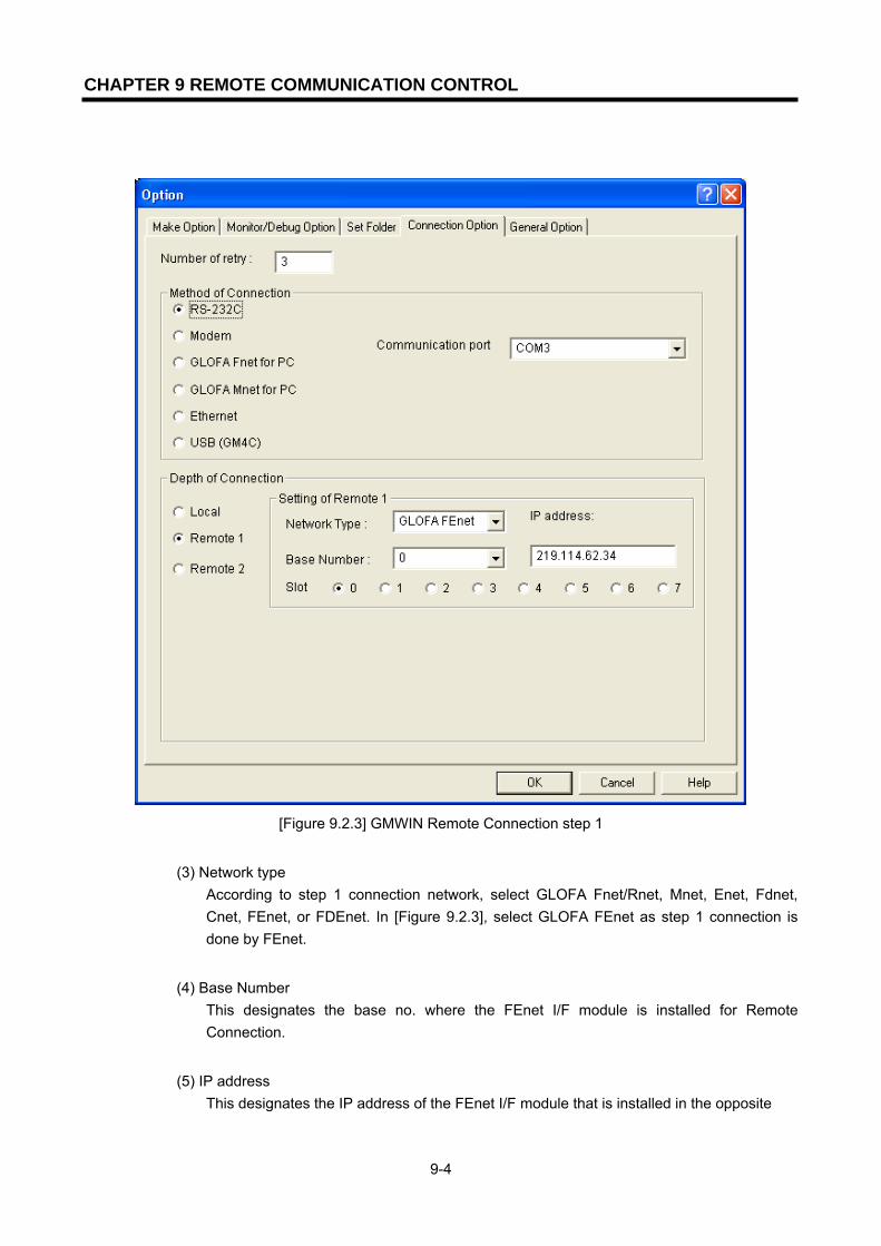
CHAPTER 9 REMOTE COMMUNICATION CONTROL
9-4
[Figure 9.2.3] GMWIN Remote Connection step 1
(3) Network type
According to step 1 connection network, select GLOFA Fnet/Rnet, Mnet, Enet, Fdnet, Cnet, FEnet, or FDEnet. In [Figure 9.2.3], select GLOFA FEnet as step 1 connection is done by FEnet.
(4) Base Number
This designates the base no. where the FEnet I/F module is installed for Remote Connection.
(5) IP address
This designates the IP address of the FEnet I/F module that is installed in the opposite

CHAPTER 9 REMOTE COMMUNICATION CONTROL
9-5
station PLC where step 1 connection is to be arranged in network 1. [Figure 9.2.3] shows the IP address (219.114.62.34) of the PLC B module.
(6) Slot
This shows the position of the communication module that is connected to network 1 in the local PLC connected by RS-232C. In [Figure 9.2.3], it is required to select ‘0’ because the FEnet installed in PLC A is in the ‘0’ slot.
From this status, select ‘OK’ and select ‘Connect’ from the online menu. When step 1 connection is completed, it has the same connection status as if a local connection is made by moving the RS-232C cable. Therefore all functions in the online menu are available (except in the case when the PLC does not match the CPU type of the currently open project).
Point
1) Notices in Remote Connection For Remote Connection, use a program suitable for the CPU type. if the CPU type does not match, only limited functions are available and program uploading/downloading and monitoring are not available.
2) Remote Connection step 2 (when using RS-232C cable)
For a Remote Connection step 2, select connection step/remote step 2 in the project / option /
connection option screen before connecting. [Figure 9.2.4] shows the example of a step 2
connection that is to be connected to a Fnet I/F module of PLC E via a FEnet I/F module of PLC
B station.
For remote step connection, select project/option/connection option and select ‘remote step 2’.
The following dialog box appears:

CHAPTER 9 REMOTE COMMUNICATION CONTROL
9-6
[Figure 9.2.4] GMWIN Remote Connection step 2
From the above dialog box, all items are the same except remote step 2 which is described below:
(1) Network Type
According to Remote Connection step 2 network, select either GLOFA Fnet/Rnet, Mnet, Enet, Fdnet, Cnet, FEnet, or FDEnet. The network of step 1 connection and step 2 connection are not related to each other. [Figure 9.2.4] step 2 connection is connected by Fnet. Therefore, step 2 should be set by GLOFA Fnet.
(2) Station No.
For remote step 2, use the station no. of the module installed in the PLC that it is to be connected. In [Figure 9.2.4], remote step 2 uses ‘5’ because it is connected to PLC E

CHAPTER 9 REMOTE COMMUNICATION CONTROL
9-7
module station no. 5.
(3) Slot It indicates the position of the module in the local station of PLC (PLC B) in the network 2. In [Figure 9.2.4], fill in the slot no. with ‘0’ because the Fnet module’s station no. is ‘3’, and it is installed in the ‘0’ slot in the PLC B.
If step 2 connection is completed, this means that the logical connection status the same as if it was connected by the moving the RS-232C cable to PLC E. Therefore, use all functions of in the online menu are available.
3) Remote Connection step 1 in a PLC connected to Ethernet If a GMWIN acting PC is connected to a PLC and a network, Remote Connection step 1 by Ethernet is available without connecting RS-232C to the PLC CPU.
[Figure 9.2.5] Remote Connection step 1 through a PC
[Figure 9.2.5] shows an example of a PC and PLC connection by Ethernet. In this case, it is possible to connect to all PLCs by network in GMWIN without using RS-232C. In this case, local connection is omitted and Remote Connection step 1 is carried out for all the PLCs. In order to carry out direct Remote Connection step 1 by Ethernet, select project/option/connection option and change the setting as shown in the dialog box below:
Desktop System
G3Q-RY4ARUNCPU I/F RUNFB-SERVECEHS-SERVICEGMWIN-SERVICEGLOFA-SERVICEFTP-SERVICEH/W-ERROR
10BASE5 ENABLE10BASE2 ENABLE10BASE-T LINK10BASE-T PLRTYTXRX
L00
01
0203
04
05
06
07
COM
L16
17
1819
04
21
22
23
COM
08L 09
1011
1213
14
15
COM
08L 25
2627
2829
30
31COM
+- DC24V
RELAYAC250V 2ADC24V 2A
PROGRAMMABLECONTROLLER
GLO
FA
GM3-PA1A
PWR
G3L-EUEA
RUNCPU I/F RUNFB-SERVECEHS-SERVICEGMWIN-SERVICEGLOFA-SERVICEFTP-SERVICEH/W-ERROR
10BASE5 ENABLE10BASE2 ENABLE10BASE-T LINK10BASE-T PLRTYTXRX
MODE
1
2345
06
7 89
0: ON.RUN1: TEST12: TEST2
EXT.POWER
DC IN
+12V
12G
FG
10BASE5
10BASE2
10BASE-T
RUN
GM1-CPUA
RUNSTOP
REMOTEFAIL
ERROR
PAU/REM
STOP
G3L-FUEA
MODE
0: ON.RUN1: TEST12: TEST2
X1
X10
CON1
CON2
1
234
5
06
7 89
1
234
5
06
7 89
1
2345
06
7 89
RUN
LAS
TOKEN
TX/RX
FAULT
G3Q-RY4ARUNCPU I/F RUNFB-SERVECEHS-SERVICEGMWIN-SERVICEGLOFA-SERVICEFTP-SERVICEH/W-ERROR
10BASE5 ENABLE10BASE2 ENABLE10BASE-T LINK10BASE-T PLRTYTXRX
L00
01
0203
04
05
06
07
COM
L16
17
1819
04
21
22
23
COM
08L 09
1011
1213
14
15
COM
08L 25
2627
2829
30
31COM
+- DC24V
RELAYAC250V 2ADC24V 2A
PROGRAMMABLECONTROLLER
GLO
FA
GM3-PA1A
PWR
G3L-EUEA
RUNCPU I/F RUNFB-SERVECEHS-SERVICEGMWIN-SERVICEGLOFA-SERVICEFTP-SERVICEH/W-ERROR
10BASE5 ENABLE10BASE2 ENABLE10BASE-T LINK10BASE-T PLRTYTXRX
MODE
1
2345
06
7 89
0: ON.RUN1: TEST12: TEST2
EXT.POWER
DC IN
+12V
12G
FG
10BASE5
10BASE2
10BASE-T
RUN
GM1-CPUA
RUNSTOP
REMOTEFAIL
ERROR
PAU/REM
STOP
G3L-FUEA
MODE
0: ON.RUN1: TEST12: TEST2
X1
X10
CON1
CON2
1
2345
06
7 89
1
2345
06
7 89
1
234
5
06
7 89
RUN
LAS
TOKEN
TX/RX
FAULT
G3Q-RY4ARUNCPU I/F RUNFB-SERVECEHS-SERVICEGMWIN-SERVICEGLOFA-SERVICEFTP-SERVICEH/W-ERROR
10BASE5 ENABLE10BASE2 ENABLE10BASE-T LINK10BASE-T PLRTYTXRX
L00
01
0203
04
05
06
07
COM
L16
17
1819
04
21
22
23
COM
08L 09
1011
1213
14
15
COM
08L 25
2627
2829
30
31COM
+- DC24V
RELAYAC250V 2ADC24V 2A
PROGRAMMABLECONTROLLER
GLO
FA
GM3-PA1A
PWR
G3L-EUEA
RUNCPU I/F RUNFB-SERVECEHS-SERVICEGMWIN-SERVICEGLOFA-SERVICEFTP-SERVICEH/W-ERROR
10BASE5 ENABLE10BASE2 ENABLE10BASE-T LINK10BASE-T PLRTYTXRX
MODE
1
2345
06
7 8 9
0: ON.RUN1: TEST12: TEST2
EXT.POWER
DC IN
+12V
12G
FG
10BASE5
10BASE2
10BASE-T
RUN
GM1-CPUA
RUNSTOP
REMOTEFAIL
ERROR
PAU/REM
STOP
G3L-FUEA
MODE
0: ON.RUN1: TEST12: TEST2
X1
X10
CON1
CON2
1
2345
06
7 89
1
2345
06
7 89
1
234
5
06
7 89
RUN
LAS
TOKEN
TX/RX
FAULT
이더넷 망(네트워크1)
GLOFA PLC A210.206.91.188
GLOFA PLC B210.206.91.189
GLOFA PLC C210.206.91.190
Ethernet (Network 1)

CHAPTER 9 REMOTE COMMUNICATION CONTROL
9-8
[Figure 9.2.6] Direct Remote Connection step 1 in a PC
(1) Method of Connection
Select the connection method. In [Figure 9.2.6], select Ethernet because Ethernet is used for a connection without using RS-232C.
(2) Depth of Connection Determine whether to select remote step 1 or remote step 2 for PLC connection. Select ‘remote step 1’ here.
(3) IP address Record the IP address of the FEnet I/F module desired to connect. [Figure 9.2.6] shows the IP address (219.114.62.34) for PLC B connection.
All of the following procedures are the same as using RS-232C. When finished, select ‘OK’ and select ‘Connect’ from the online menu.

CHAPTER 9 REMOTE COMMUNICATION CONTROL
9-9
The following table shows the relationship between the device (Client), requires the connection of the RS-232C cable connected to the GMWIN communication service of the GLOFA PLC network, and the device (Server) connection according to the connection request.
SERVER
CLIENT
PC-module
(GMWIN)GM1 GM2 GM3 GM4 GM6
PC-module(GMWIN) X O O O O O
GM1 X O O O O O
GM2 X O O O O O
GM3 X O O O O O
GM4 X O O O O O
GM6 X O O O O O
[Table 9.2.1] GMWIN Client and Server relationship
3) Direct Remote Connection step 2 in the PLC connected to Ethernet In [Figure 9.2.1], if the GMWIN acting PC is connected to a PLC by network, Remote Connection step 2 by Ethernet is available and the method is the same as remote step 1. An example of setting the connection option is shown below:
[Figure 9.2.7] Direct Remote Connection step 2 in the PC
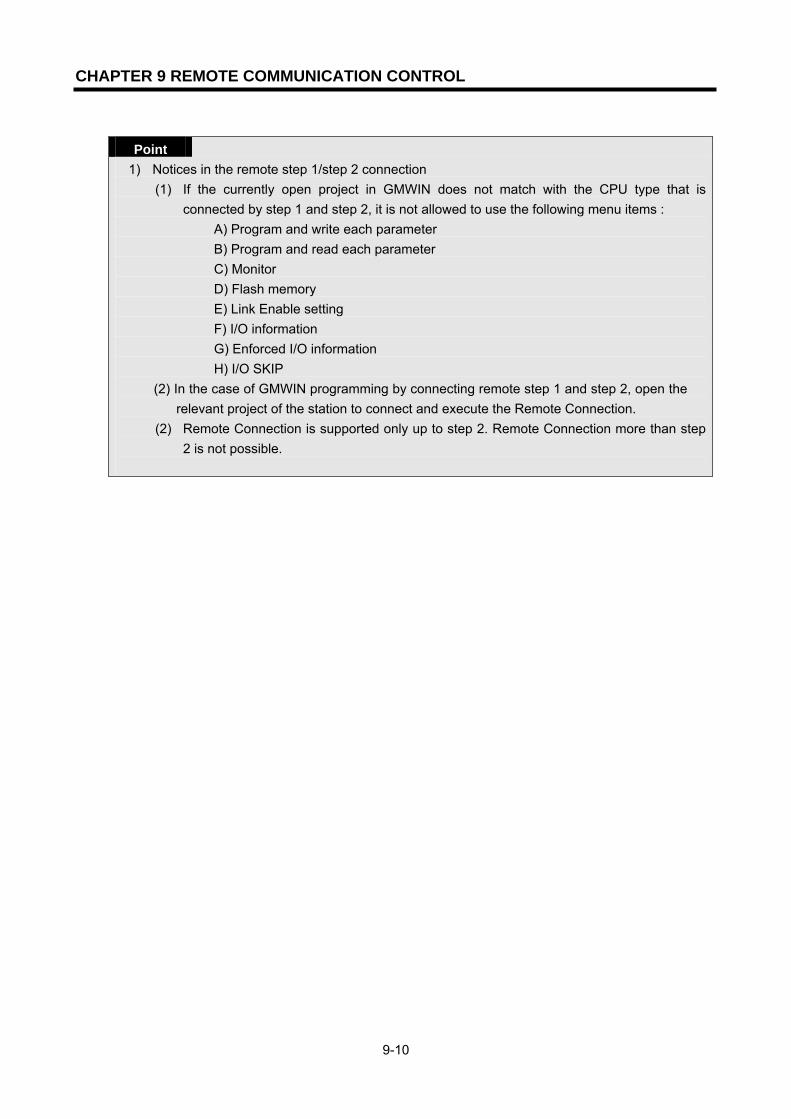
CHAPTER 9 REMOTE COMMUNICATION CONTROL
9-10
Point
1) Notices in the remote step 1/step 2 connection (1) If the currently open project in GMWIN does not match with the CPU type that is
connected by step 1 and step 2, it is not allowed to use the following menu items : A) Program and write each parameter B) Program and read each parameter C) Monitor D) Flash memory E) Link Enable setting F) I/O information G) Enforced I/O information H) I/O SKIP
(2) In the case of GMWIN programming by connecting remote step 1 and step 2, open the relevant project of the station to connect and execute the Remote Connection.
(2) Remote Connection is supported only up to step 2. Remote Connection more than step 2 is not possible.

CHAPTER 9 REMOTE COMMUNICATION CONTROL
9-11
9.3 KGLWIN Settings and Connections
All PLC’s (K1000S/K300S/K200S station) connected by the Master-K network are available to connect each other by the KGLWIN communication service. KGLWIN Remote Connection is composed of step 1 connection and step 2 connection. The following described the step 1 and step 2 connection method. [Figure 9.3.1] shows step 1 (PLC A,PLC B) and step 2 (PLC C) connection in the system composed of two networks.
[Figure 9.3.1] KGLWIN Remote Connection [Figure 9.2.1] shows step 1 (PLC B) and step 2 (PLC E) connection in the system composed of two networks.
1) Remote Connection step 1 (when using RS-232C cable) For Remote Connection step 1, KGLWIN should be offline. In this state, if you select [option] from project menu, the [option dialogue] box appears as follows. Select ‘connection option’ tab here. [Figure 9.3.2] shows the Remote Connection screen and the setting method is almost the same as GLOFA.
Desktop System
G3Q-RY4A
RUNCPU I/F RUNFB-SERVECEHS-SERVICEGMWIN-SERVICEGLOFA-SERVICEFTP-SERVICEH/W-ERROR
10BASE5 ENABLE10BASE2 ENABLE10BASE-T LINK10BASE-T PLRTYTXRX
L00
01
0203
04
05
06
07
COM
L16
17
18
19
04
21
22
23
COM
08L 09
1011
1213
14
15
COM
08L 25
26
27
2829
30
31COM
+- DC24V
RELAYAC250V 2ADC24V 2A
PROGRAMMABLECONTROLLER
GLO
FA
GM3-PA1A
PWR
G3L-EUEA
RUNCPU I/F RUNFB-SERVECEHS-SERVICEGMWIN-SERVICEGLOFA-SERVICEFTP-SERVICEH/W-ERROR
10BASE5 ENABLE10BASE2 ENABLE10BASE-T LINK10BASE-T PLRTYTXRX
MODE
1
234
5
06
7 89
0: ON.RUN1: TEST12: TEST2
EXT.POWER
DC IN
+12V
12G
FG
10BASE5
10BASE2
10BASE-T
RUN
GM1-CPUA
RUNSTOP
REMOTEFAIL
ERROR
PAU/REM
STOP
G3L-FUEA
MODE
0: ON.RUN1: TEST12: TEST2
X1
X10
CON1
CON2
1234
5
06
789
1
234
5
06
789
1
234
5 06
7 89
RUN
LAS
TOKEN
TX/RX
FAULT
G3Q-RY4A
RUNCPU I/F RUNFB-SERVECEHS-SERVICEGMWIN-SERVICEGLOFA-SERVICEFTP-SERVICEH/W-ERROR
10BASE5 ENABLE10BASE2 ENABLE10BASE-T LINK10BASE-T PLRTYTXRX
L00
01
0203
04
05
06
07
COM
L16
17
18
19
04
21
22
23
COM
08L 09
1011
1213
14
15
COM
08L 25
26
27
2829
30
31COM
+- DC24V
RELAYAC250V 2ADC24V 2A
PROGRAMMABLECONTROLLER
GLO
FA
GM3-PA1A
PWR
G3L-EUEA
RUNCPU I/F RUNFB-SERVECEHS-SERVICEGMWIN-SERVICEGLOFA-SERVICEFTP-SERVICEH/W-ERROR
10BASE5 ENABLE10BASE2 ENABLE10BASE-T LINK10BASE-T PLRTYTXRX
MODE
1
234
5
06
789
0: ON.RUN1: TEST12: TEST2
EXT.POWER
DC IN
+12V
12G
FG
10BASE5
10BASE2
10BASE-T
RUN
GM1-CPUA
RUNSTOP
REMOTEFAIL
ERROR
PAU/REM
STOP
G3L-FUEA
MODE
0: ON.RUN1: TEST12: TEST2
X1
X10
CON1
CON2
1234
5
06
789
1
234
5
06
789
1
234
5 06
7 89
RUN
LAS
TOKEN
TX/RX
FAULT
G3Q-RY4A
RUNCPU I/F RUNFB-SERVECEHS-SERVICEGMWIN-SERVICEGLOFA-SERVICEFTP-SERVICEH/W-ERROR
10BASE5 ENABLE10BASE2 ENABLE10BASE-T LINK10BASE-T PLRTYTXRX
L00
01
0203
04
05
06
07
COM
L16
17
18
19
04
21
22
23
COM
08L 09
1011
1213
14
15
COM
08L 25
26
27
2829
30
31COM
+- DC24V
RELAYAC250V 2ADC24V 2A
PROGRAMMABLECONTROLLER
GLO
FA
GM3-PA1A
PWR
G3L-EUEA
RUNCPU I/F RUNFB-SERVECEHS-SERVICEGMWIN-SERVICEGLOFA-SERVICEFTP-SERVICEH/W-ERROR
10BASE5 ENABLE10BASE2 ENABLE10BASE-T LINK10BASE-T PLRTYTXRX
MODE
1
234
5
06
7 89
0: ON.RUN1: TEST12: TEST2
EXT.POWER
DC IN
+12V
12G
FG
10BASE5
10BASE2
10BASE-T
RUN
GM1-CPUA
RUNSTOP
REMOTEFAIL
ERROR
PAU/REM
STOP
G3L-FUEA
MODE
0: ON.RUN1: TEST12: TEST2
X1
X10
CON1
CON2
1234
5
06
789
1
234
5
06
789
1
234
5 06
789
RUN
LAS
TOKEN
TX/RX
FAULT
G3Q-RY4ARUNCPU I/F RUNFB-SERVECEHS-SERVICEGMWIN-SERVICEGLOFA-SERVICEFTP-SERVICEH/W-ERROR
10BASE5 ENABLE10BASE2 ENABLE10BASE-T LINK10BASE-T PLRTYTXRX
L00
01
02
03
04
05
06
07
COM
L16
17
18
19
04
21
22
23
COM
08L 09
1011
1213
14
15
COM
08L 25
2627
28
29
30
31
COM
+- DC24V
RELAYAC250V 2ADC24V 2A
PROGRAMMABLECONTROLLER
GLO
FA
GM3-PA1A
PWR
G3L-EUEA
RUNCPU I/F RUNFB-SERVECEHS-SERVICEGMWIN-SERVICEGLOFA-SERVICEFTP-SERVICEH/W-ERROR
10BASE5 ENABLE10BASE2 ENABLE10BASE-T LINK10BASE-T PLRTYTXRX
MODE
1
234
5
06
78 9
0: ON.RUN1: TEST12: TEST2
EXT.POWER
DC IN
+12V
12G
FG
10BASE5
10BASE2
10BASE-T
RUN
GM1-CPUA
RUNSTOP
REMOTEFAIL
ERROR
PAU/REM
STOP
G3L-FUEA
MODE
0: ON.RUN1: TEST12: TEST2
X1
X10
CON1
CON2
1
234
5
06
789
1
234
5
06
789
1
234
5
06
789
RUN
LAS
TOKEN
TX/RX
FAULT
G3Q-RY4ARUNCPU I/F RUNFB-SERVECEHS-SERVICEGMWIN-SERVICEGLOFA-SERVICEFTP-SERVICEH/W-ERROR
10BASE5 ENABLE10BASE2 ENABLE10BASE-T LINK10BASE-T PLRTYTXRX
L00
01
02
03
04
05
06
07
COM
L16
17
18
19
04
21
22
23
COM
08L 09
1011
1213
14
15
COM
08L 25
2627
28
29
30
31
COM
+- DC24V
RELAYAC250V 2ADC24V 2A
PROGRAMMABLECONTROLLER
GLO
FA
GM3-PA1A
PWR
G3L-EUEA
RUNCPU I/F RUNFB-SERVECEHS-SERVICEGMWIN-SERVICEGLOFA-SERVICEFTP-SERVICEH/W-ERROR
10BASE5 ENABLE10BASE2 ENABLE10BASE-T LINK10BASE-T PLRTYTXRX
MODE
1
2345
06
789
0: ON.RUN1: TEST12: TEST2
EXT.POWER
DC IN
+12V
12G
FG
10BASE5
10BASE2
10BASE-T
RUN
GM1-CPUA
RUNSTOP
REMOTEFAIL
ERROR
PAU/REM
STOP
G3L-FUEA
MODE
0: ON.RUN1: TEST12: TEST2
X1
X10
CON1
CON2
1
234
5
06
789
1
234
5
06
789
1
234
5
06
7 89
RUN
LAS
TOKEN
TX/RX
FAULT
이더넷 망(네트워크1)
RS232C로컬 접속
FNET 망(네트워크2)
GLOFA PLC A210.206.91.188
GLOFA PLC B210.206.91.189
GLOFA PLC C210.206.91.190
GLOFA PLC D GLOFA PLC E
리모트 1단 접속
리모트 2단 접속
ENET
Remote Connection Step 1
Remote Connection Step 2
MK PKC A MK PKC B MK PKC C
MK PKC E MK PKC F

CHAPTER 9 REMOTE COMMUNICATION CONTROL
9-12
[Figure 9.3.2] Remote Connection screen
(1) Type
Select either GLOFA Fnet/Rnet, Mnet, Enet, Fdnet, Cnet, FEnet, or FDEnet according to step 1 connection network. In [Figure 9.3.2], since step 1 connection is done through FEnet, select GLOFA FEnet.
(2) Base
This is to designate the base no. that the FEnet I/F module for Remote Connection is installed.
(3) Slot
This shows the position of the communication module that is connected to network 1 of the local PLC connected by RS-232C. In [Figure 9.3.1], it is required to select ‘0’ because FEnet installed in PLC A is in the ‘0’ slot.

CHAPTER 9 REMOTE COMMUNICATION CONTROL
9-13
(4) IP address
This designates the IP address of the FEnet I/F module that is installed in the opposite station PLC. where the step 1 connection is to be arranged in the network 1. [Figure 9.3.2] shows the IP address (219.114.62.34) of the PLC B module.
In this state, click the ‘OK’ button to complete the setting. If the user selects the online-connection menu and the Remote Connection step 1 is arranged normally, the PLC model and connection status will be displayed on the bottom of the KGLWIN screen. In the case of a connection failure, this indicates that there is a communication line or an internal protocol error or that the setting value of the Remote Connection is not proper. If this is the case, check if the setting is OK and try the connection again.
2) Remote Connection step 2 Select [project]->[option]->[connection option] in the menu and set the connection step to remote step 2. In [Figure 9.3.3], the step 2 connection is processed through KGLWIN PLC A FEnet PLC B FEnet PLC B Fnet PLC C Fnet module. For the Remote Connection step 2, select [project]->[option]->[connection option] in the menu and select remote step 2 in the connection step as shown on the screen below.
[Figure 9.3.3] Remote Connection step 2 screen

CHAPTER 9 REMOTE COMMUNICATION CONTROL
9-14
(1) Slot
For remote step 1 slot no., fill in ‘0’ if the PLC A module is installed for the connection of PLC A PLC B. For remote step 2 slot no., fill in ‘1’ if the PLC B communication module is installed for step 2 connection from PLC B PLC C.
(2) Station no.
This designates the station no. which is connected by remote step 1 and the station no. which is connected by remote step 2, respectively. For Remote Connection step 1, input station no. 1 of PLC B. For remote step 2, input station no. 5 of PLC C. After setting the network type, station no., slot no. as the same value as above, select ‘OK’ in the dialog box. A message saying “connection is completed” is displayed on the bottom of KGLWIN screen. This means that step 2 connection is completed. This is a logical connection state that is the same as if it is connected by moving the RS-232C cable to PLC C. All online menus are available to be used. [Table 9.3.1] shows the possible relationships for the connection between the device (Client) that requires the connection of the RS-232C cable that is connected to KGLWIN communication service and the device (server) that connects according to the connection request by Fnet communication.
SERVER
CLIENT
PC-module
(KGLWIN) K1000S K300S K200S
PC-module(KGLWIN) X O O O
K1000S X O O O
K300S X O O O
K200S X O O O
[Table 9.3.1] KGLWIN Client and Server relationship
3) Direct Remote Connection step 2 to a PC connected by Ethernet In [Figure 9.3.1], if the KGLWIN acting PC is connected to a PLC by network, Remote Connection step 2 by Ethernet is available and the method is the same as remote step 1 and the setting example of the connection option is as follows :

CHAPTER 9 REMOTE COMMUNICATION CONTROL
9-15
[Figure 9.3.4] Direct Remote Connection step 2 in a PC
Point
1) Notices in remote step 1/step 2 connection (1) Remote Connection is not possible if the currently open project in KGLWIN does not match
with the CPU type that is connected by step 1 and step 2. (2) In the case of programming KGLWIN by connecting remote step 1 and step 2, open the
relevant project of the station to connect and execute the Remote Connection. (3) Remote Connection is supported only up to step 2. Remote Connection greater than step 2
is not possible. (4) Master-K and GLOFA have the same connection method, so the settings are the same with
GLOFA.
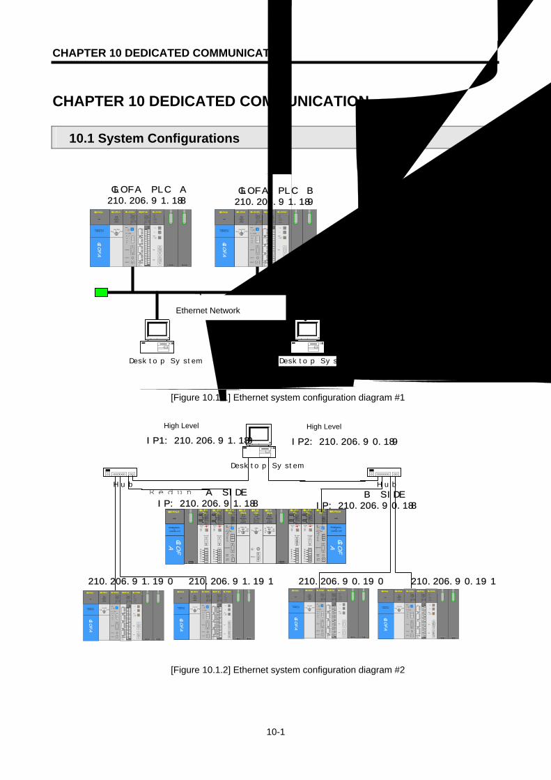
CHAPTER 10 DEDICATED COMMUNICATION
10-1
CHAPTER 10 DEDICATED COMMUNICATION
10.1 System Configurations
[Figure 10.1.1] Ethernet system configuration diagram #1
[Figure 10.1.2] Ethernet system configuration diagram #2
210.206.91.190 210.206.90.191
G3L-EUEA
RUNCPU I/F RUNFB-SERVECEHS-SERVICEGMWIN-SERVICEGLOFA-SERVICEFTP-SERVICEH/W-ERROR
10BASE5 ENABLE10BASE2 ENABLE10BASE-T LINK10BASE-T PLRTYTXRXMO
DE12345
06 7890: ON.RUN1: TEST12: TEST2EXT.POWER
DC IN
+12V12GFG
10BASE5
10BASE2
10BASE-T
RUN
GM1-CPUARUNSTOP
REMOTEFAIL
ERROR
PAU/REM ST
OPA
GM1-DIFA
A SELA+B
B AELCPU-ACPU-B
A+B
B
EXTPWR
RS232C
RUN
GM1-CPUARUNSTOP
REMOTEFAIL
ERROR
PAU/REM ST
OP
PROGRAMMABLE
CONTROLLER
GLO
FA
GM3-PA1A
PWR
G3L-EUEA
RUN/BPSTX/BPSRS/BPSACK/DATA-BITNAK/PARITYERR/EVEN-ODDNODEM/STOP-BITSYS-RUN
MODE
RS-232C
1234
5 06 789
DISPLAY
RS-422
RDA
RDBSDA
SDBSG
FG
RUN/BPSTX/BPSRX/BPSACK/DATA-BITNAK/PARITYERR/EVEN-ODDRS-485/STOP-BITSYS-ERROR
RS-232C
RS-422
G3L-EUEA
RUN/BPSTX/BPSRS/BPSACK/DATA-BITNAK/PARITYERR/EVEN-ODDNODEM/STOP-BITSYS-RUN
MODE
RS-232C
12345
06 789
DISPLAY
RS-422RDARDBSDASDB
SG
FG
RUN/BPSTX/BPSRX/BPSACK/DATA-BITNAK/PARITYERR/EVEN-ODDRS-485/STOP-BITSYS-ERROR
RS-232C
RS-422
G3L-EUEA
RUNCPU I/F RUNFB-SERVECEHS-SERVICEGMWIN-SERVICEGLOFA-SERVICEFTP-SERVICEH/W-ERROR
10BASE5 ENABLE10BASE2 ENABLE10BASE-T LINK10BASE-T PLRTYTXRXMO
DE12345
067890: ON.RUN1: TEST12: TEST2EXT.POWER
DC IN
+12V12GFG
10BASE5
10BASE2
10BASE-T
PROGRAMMABLE
CONTROLLER
GLO
FA
GM3-PA1A
PWR
G3L-EUEA
RUN/BPSTX/BPSRS/BPSACK/DATA-BITNAK/PARITYERR/EVEN-ODDNODEM/STOP-BITSYS-RUN
MODE
RS-232C
12345
06 789
DISPLAY
RS-422
RDARDBSDASDB
SG
FG
RUN/BPSTX/BPSRX/BPSACK/DATA-BITNAK/PARITYERR/EVEN-ODDRS-485/STOP-BITSYS-ERROR
RS-232C
RS-422
G3L-EUEA
RUN/BPSTX/BPSRS/BPSACK/DATA-BITNAK/PARITYERR/EVEN-ODDNODEM/STOP-BITSYS-RUN
MODE
RS-232C
1234
5 06 789
DISPLAY
RS-422RDARDBSDASDB
SG
FG
RUN/BPSTX/BPSRX/BPSACK/DATA-BITNAK/PARITYERR/EVEN-ODDRS-485/STOP-BITSYS-ERROR
RS-232C
RS-422
Desktop System
Hub
G3Q-RY4A
RUNCPU I/F RUNFB-SERVECEHS-SERVICEGMWIN-SERVICEGLOFA-SERVICEFTP-SERVICEH/W-ERROR
10BASE5 ENABLE10BASE2 ENABLE10BASE-T LINK10BASE-T PLRTYTXRX
L00
01
02
03
04
05
06
07
COM
L16
17
18
19
04
21
22
23
COM
08L09
1011
1213
14
15
COM
08L 25
26
27
2829
30
31
COM
+- DC24V
RELAYAC250V 2ADC24V 2A
PROGRAMMABLECONTROLLER
GLO
FA
GM3-PA1A
PWR
G3L-EUEA
RUNCPU I/F RUNFB-SERVECEHS-SERVICEGMWIN-SERVICEGLOFA-SERVICEFTP-SERVICEH/W-ERROR
10BASE5 ENABLE10BASE2 ENABLE10BASE-T LINK10BASE-T PLRTYTXRX
MODE
1
2345
06
7 8 9
0: ON.RUN1: TEST12: TEST2
EXT.POWER
DC IN
+12V
12G
FG
10BASE5
10BASE2
10BASE-T
RUN
GM1-CPUA
RUNSTOP
REMOTEFAIL
ERROR
PAU/REM
STOP
G3L-FUEA
MODE
0: ON.RUN1: TEST12: TEST2
X1
X10
CON1
CON2
1
2345
06
7 8 9
1
2345
06
7 8 9
1
234
5
06
7 89
RUN
LAS
TOKEN
TX/RX
FAULT
Hub
G3Q-RY4A
RUNCPU I/F RUNFB-SERVECEHS-SERVICEGMWIN-SERVICEGLOFA-SERVICEFTP-SERVICEH/W-ERROR
10BASE5 ENABLE10BASE2 ENABLE10BASE-T LINK10BASE-T PLRTYTXRX
L00
01
0203
04
05
06
07
COM
L16
17
18
19
04
21
22
23
COM
08L09
1011
1213
14
15
COM
08L 25
2627
28
29
30
31
COM
+- DC24V
RELAYAC250V 2ADC24V 2A
PROGRAMMABLECONTROLLER
GLO
FA
GM3-PA1A
PWR
G3L-EUEA
RUNCPU I/F RUNFB-SERVECEHS-SERVICEGMWIN-SERVICEGLOFA-SERVICEFTP-SERVICEH/W-ERROR
10BASE5 ENABLE10BASE2 ENABLE10BASE-T LINK10BASE-T PLRTYTXRX
MODE
1
2345
06
7 89
0: ON.RUN1: TEST12: TEST2
EXT.POWER
DC IN
+12V
12G
FG
10BASE5
10BASE2
10BASE-T
RUN
GM1-CPUA
RUNSTOP
REMOTEFAIL
ERROR
PAU/REM
STOP
G3L-FUEA
MODE
0: ON.RUN1: TEST12: TEST2
X1
X10
CON1
CON2
1
234
5
06
7 8 9
1
2345
06
7 8 9
1
234
5
06
7 89
RUN
LAS
TOKEN
TX/RX
FAULT
G3Q-RY4A
RUNCPU I/F RUNFB-SERVECEHS-SERVICEGMWIN-SERVICEGLOFA-SERVICEFTP-SERVICEH/W-ERROR
10BASE5 ENABLE10BASE2 ENABLE10BASE-T LINK10BASE-T PLRTYTXRX
L00
01
0203
04
05
06
07
COM
L16
17
18
19
04
21
22
23
COM
08L09
1011
1213
14
15
COM
08L 25
2627
28
29
30
31
COM
+- DC24V
RELAYAC250V 2ADC24V 2A
PROGRAMMABLECONTROLLER
GLO
FA
GM3-PA1A
PWR
G3L-EUEA
RUNCPU I/F RUNFB-SERVECEHS-SERVICEGMWIN-SERVICEGLOFA-SERVICEFTP-SERVICEH/W-ERROR
10BASE5 ENABLE10BASE2 ENABLE10BASE-T LINK10BASE-T PLRTYTXRX
MODE
1
2345
06
7 89
0: ON.RUN1: TEST12: TEST2
EXT.POWER
DC IN
+12V
12G
FG
10BASE5
10BASE2
10BASE-T
RUN
GM1-CPUA
RUNSTOP
REMOTEFAIL
ERROR
PAU/REM
STOP
G3L-FUEA
MODE
0: ON.RUN1: TEST12: TEST2
X1
X10
CON1
CON2
1
234
5
06
7 8 9
1
234
5
06
7 8 9
1
234
5
06
7 89
RUN
LAS
TOKEN
TX/RX
FAULT
G3Q-RY4A
RUNCPU I/F RUNFB-SERVECEHS-SERVICEGMWIN-SERVICEGLOFA-SERVICEFTP-SERVICEH/W-ERROR
10BASE5 ENABLE10BASE2 ENABLE10BASE-T LINK10BASE-T PLRTYTXRX
L00
01
0203
04
05
06
07
COM
L16
17
18
19
04
21
22
23
COM
08L 09
1011
1213
14
15
COM
08L25
26
27
28
29
30
31COM
+- DC24V
RELAYAC250V 2ADC24V 2A
PROGRAMMABLECONTROLLER
GLO
FA
GM3-PA1A
PWR
G3L-EUEA
RUNCPU I/F RUNFB-SERVECEHS-SERVICEGMWIN-SERVICEGLOFA-SERVICEFTP-SERVICEH/W-ERROR
10BASE5 ENABLE10BASE2 ENABLE10BASE-T LINK10BASE-T PLRTYTXRX
MODE
1
2345
06
7 89
0: ON.RUN1: TEST12: TEST2
EXT.POWER
DC IN
+12V
12G
FG
10BASE5
10BASE2
10BASE-T
RUN
GM1-CPUA
RUNSTOP
REMOTEFAIL
ERROR
PAU/REM
STOP
G3L-FUEA
MODE
0: ON.RUN1: TEST12: TEST2
X1
X10
CON1
CON2
1
2345
06
7 89
1
234
5
06
7 89
1
2345
06
7 89
RUN
LAS
TOKEN
TX/RX
FAULT
상위IP1:210.206.91.189
상위IP2:210.206.90.189
이중화 A SIDEIP:210.206.91.188
이중화 B SIDEIP:210.206.90.188
210.206.91.191 210.206.90.190
G3Q-RY4ARUNCPU I/F RUNFB-SERVECEHS-SERVICEGMWIN-SERVICEGLOFA-SERVICEFTP-SERVICEH/W-ERROR
10BASE5 ENABLE10BASE2 ENABLE10BASE-T LINK10BASE-T PLRTYTXRX
L00
01
0203
04
05
06
07
COM
L16
17
18
19
04
21
22
23
COM
08L 09
1011
1213
14
15
COM
08L 25
2627
2829
30
31COM
+- DC24V
RELAYAC250V 2ADC24V 2A
PROGRAMMABLECONTROLLER
GLO
FA
GM3-PA1A
PWR
G3L-EUEA
RUNCPU I/F RUNFB-SERVECEHS-SERVICEGMWIN-SERVICEGLOFA-SERVICEFTP-SERVICEH/W-ERROR
10BASE5 ENABLE10BASE2 ENABLE10BASE-T LINK10BASE-T PLRTYTXRX
MODE
1
2345
06
7 8 9
0: ON.RUN1: TEST12: TEST2
EXT.POWER
DC IN
+12V
12G
FG
10BASE5
10BASE2
10BASE-T
RUN
GM1-CPUA
RUNSTOP
REMOTEFAIL
ERROR
PAU/REM
STOP
G3L-FUEA
MODE
0: ON.RUN1: TEST12: TEST2
X1
X10
CON1
CON2
1
2345
06
7 8 9
1
2345
06
7 8 9
1
2345
06
7 89
RUN
LAS
TOKEN
TX/RX
FAULT
이더넷 망(네트워크1)
GLOFA PLC A210.206.91.188
GLOFA PLC B210.206.91.189
GLOFA PLC C210.206.91.190
Desktop System Desktop System
Ethernet Network
High Level High Level
Redundant

CHAPTER 10 DEDICATED COMMUNICATION
10-2
[Figure 10.1.3] Ethernet system configuration diagram #3
[Figure 10.1.4] Ethernet system configuration diagram #4
상위IP1:210.206.91.192IP2:210.206.90.192
210.206.91.190 210.206.90.191
Desktop System
Hub
G3Q-RY4A
RUNCPU I/F RUNFB-SERVECEHS-SERVICEGMWIN-SERVICEGLOFA-SERVICEFTP-SERVICEH/W-ERROR
10BASE5 ENABLE10BASE2 ENABLE10BASE-T LINK10BASE-T PLRTYTXRX
L00
01
02
03
04
05
06
07
COM
L16
17
18
19
04
21
22
23
COM
08L09
1011
1213
14
15
COM
08L 25
26
27
2829
30
31COM
+- DC24V
RELAYAC250V 2ADC24V 2A
PROGRAMMABLECONTROLLER
GLO
FA
GM3-PA1A
PWR
G3L-EUEA
RUNCPU I/F RUNFB-SERVECEHS-SERVICEGMWIN-SERVICEGLOFA-SERVICEFTP-SERVICEH/W-ERROR
10BASE5 ENABLE10BASE2 ENABLE10BASE-T LINK10BASE-T PLRTYTXRX
MODE
1
2345
06
7 89
0: ON.RUN1: TEST12: TEST2
EXT.POWER
DC IN
+12V
12G
FG
10BASE5
10BASE2
10BASE-T
RUN
GM1-CPUA
RUNSTOP
REMOTEFAIL
ERROR
PAU/REM
STOP
G3L-FUEA
MODE
0: ON.RUN1: TEST12: TEST2
X1
X10
CON1
CON2
1
234
5
06
7 89
1
2345
06
7 89
1
2345
06
7 89
RUN
LAS
TOKEN
TX/RX
FAULT
Hub
G3Q-RY4ARUNCPU I/F RUNFB-SERVECEHS-SERVICEGMWIN-SERVICEGLOFA-SERVICEFTP-SERVICEH/W-ERROR
10BASE5 ENABLE10BASE2 ENABLE10BASE-T LINK10BASE-T PLRTYTXRX
L00
01
02
03
04
05
06
07
COM
L16
17
18
19
04
21
22
23
COM
08L 09
1011
1213
14
15
COM
08L25
26
27
2829
30
31COM
+- DC24V
RELAYAC250V 2ADC24V 2A
PROGRAMMABLECONTROLLER
GLO
FA
GM3-PA1A
PWR
G3L-EUEA
RUNCPU I/F RUNFB-SERVECEHS-SERVICEGMWIN-SERVICEGLOFA-SERVICEFTP-SERVICEH/W-ERROR
10BASE5 ENABLE10BASE2 ENABLE10BASE-T LINK10BASE-T PLRTYTXRX
MODE
1
234
5
06
7 89
0: ON.RUN1: TEST12: TEST2
EXT.POWER
DC IN
+12V
12G
FG
10BASE5
10BASE2
10BASE-T
RUN
GM1-CPUA
RUNSTOP
REMOTEFAIL
ERROR
PAU/REM
STOP
G3L-FUEA
MODE
0: ON.RUN1: TEST12: TEST2
X1
X10
CON1
CON2
1
2345
06
7 8 9
1
2345
06
7 8 9
1
2345
06
7 89
RUN
LAS
TOKEN
TX/RX
FAULT
G3Q-RY4ARUNCPU I/F RUNFB-SERVECEHS-SERVICEGMWIN-SERVICEGLOFA-SERVICEFTP-SERVICEH/W-ERROR
10BASE5 ENABLE10BASE2 ENABLE10BASE-T LINK10BASE-T PLRTYTXRX
L00
01
0203
04
05
06
07
COM
L16
17
18
19
04
21
22
23
COM
08L 09
1011
1213
14
15
COM
08L 25
2627
28
29
30
31
COM
+- DC24V
RELAYAC250V 2ADC24V 2A
PROGRAMMABLECONTROLLER
GLO
FA
GM3-PA1A
PWR
G3L-EUEA
RUNCPU I/F RUNFB-SERVECEHS-SERVICEGMWIN-SERVICEGLOFA-SERVICEFTP-SERVICEH/W-ERROR
10BASE5 ENABLE10BASE2 ENABLE10BASE-T LINK10BASE-T PLRTYTXRX
MODE
1
2345
06
7 89
0: ON.RUN1: TEST12: TEST2
EXT.POWER
DC IN
+12V
12G
FG
10BASE5
10BASE2
10BASE-T
RUN
GM1-CPUA
RUNSTOP
REMOTEFAIL
ERROR
PAU/REM
STOP
G3L-FUEA
MODE
0: ON.RUN1: TEST12: TEST2
X1
X10
CON1
CON2
1
234
5
06
7 89
1
2345
06
7 89
1
2345
06
7 89
RUN
LAS
TOKEN
TX/RX
FAULT
G3Q-RY4ARUNCPU I/F RUNFB-SERVECEHS-SERVICEGMWIN-SERVICEGLOFA-SERVICEFTP-SERVICEH/W-ERROR
10BASE5 ENABLE10BASE2 ENABLE10BASE-T LINK10BASE-T PLRTYTXRX
L00
01
0203
04
05
06
07
COM
L16
17
18
19
04
21
22
23
COM
08L 09
1011
1213
14
15
COM
08L 25
2627
28
29
30
31
COM
+- DC24V
RELAYAC250V 2ADC24V 2A
PROGRAMMABLECONTROLLER
GLO
FA
GM3-PA1A
PWR
G3L-EUEARUNCPU I/F RUNFB-SERVECEHS-SERVICEGMWIN-SERVICEGLOFA-SERVICEFTP-SERVICEH/W-ERROR
10BASE5 ENABLE10BASE2 ENABLE10BASE-T LINK10BASE-T PLRTYTXRX
MODE
1
2345
06
7 8 9
0: ON.RUN1: TEST12: TEST2
EXT.POWER
DC IN
+12V
12G
FG
10BASE5
10BASE2
10BASE-T
RUN
GM1-CPUA
RUNSTOP
REMOTEFAIL
ERROR
PAU/REM
STOP
G3L-FUEA
MODE
0: ON.RUN1: TEST12: TEST2
X1
X10
CON1
CON2
1
2345
06
7 89
1
234
5
06
7 89
1
2345
06
7 89
RUN
LAS
TOKEN
TX/RX
FAULT
상위IP1:210.206.91.189IP2:210.206.90.189
210.206.91.191 210.206.90.190
IBM Compatible
G3Q-RY4A
RUNCPU I/F RUNFB-SERVECEHS-SERVICEGMWIN-SERVICEGLOFA-SERVICEFTP-SERVICEH/W-ERROR
10BASE5 ENABLE10BASE2 ENABLE10BASE-T LINK10BASE-T PLRTYTXRX
L00
01
0203
04
05
06
07
COM
L16
17
18
19
04
21
22
23
COM
08L09
1011
1213
14
15
COM
08L 25
2627
2829
30
31
COM
+- DC24V
RELAYAC250V 2ADC24V 2A
PROGRAMMABLECONTROLLER
GLO
FA
GM3-PA1A
PWR
G3L-EUEA
RUNCPU I/F RUNFB-SERVECEHS-SERVICEGMWIN-SERVICEGLOFA-SERVICEFTP-SERVICEH/W-ERROR
10BASE5 ENABLE10BASE2 ENABLE10BASE-T LINK10BASE-T PLRTYTXRX
MODE
1
2345
06
7 89
0: ON.RUN1: TEST12: TEST2
EXT.POWER
DC IN
+12V
12G
FG
10BASE5
10BASE2
10BASE-T
RUN
GM1-CPUA
RUNSTOP
REMOTEFAIL
ERROR
PAU/REM
STOP
G3L-FUEA
MODE
0: ON.RUN1: TEST12: TEST2
X1
X10
CON1
CON2
1234
5
06
7 89
1
2345
06
7 89
1
234
5
06
7 89
RUN
LAS
TOKEN
TX/RX
FAULT
G3Q-RY4A
RUNCPU I/F RUNFB-SERVECEHS-SERVICEGMWIN-SERVICEGLOFA-SERVICEFTP-SERVICEH/W-ERROR
10BASE5 ENABLE10BASE2 ENABLE10BASE-T LINK10BASE-T PLRTYTXRX
L00
01
0203
04
05
06
07
COM
L16
17
18
19
04
21
22
23
COM
08L 09
1011
1213
14
15
COM
08L 25
2627
28
29
30
31
COM
+- DC24V
RELAYAC250V 2ADC24V 2A
PROGRAMMABLECONTROLLER
GLO
FA
GM3-PA1A
PWR
G3L-EUEA
RUNCPU I/F RUNFB-SERVECEHS-SERVICEGMWIN-SERVICEGLOFA-SERVICEFTP-SERVICEH/W-ERROR
10BASE5 ENABLE10BASE2 ENABLE10BASE-T LINK10BASE-T PLRTYTXRX
MODE
1
2345
06
7 89
0: ON.RUN1: TEST12: TEST2
EXT.POWER
DC IN
+12V
12G
FG
10BASE5
10BASE2
10BASE-T
RUN
GM1-CPUA
RUNSTOP
REMOTEFAIL
ERROR
PAU/REM
STOP
G3L-FUEA
MODE
0: ON.RUN1: TEST12: TEST2
X1
X10
CON1
CON2
1
2345
06
7 8 9
1
234
5
06
7 8 9
1
234
5
06
7 89
RUN
LAS
TOKEN
TX/RX
FAULT
210.206.91.188 210.206.90.188
High Level High Level
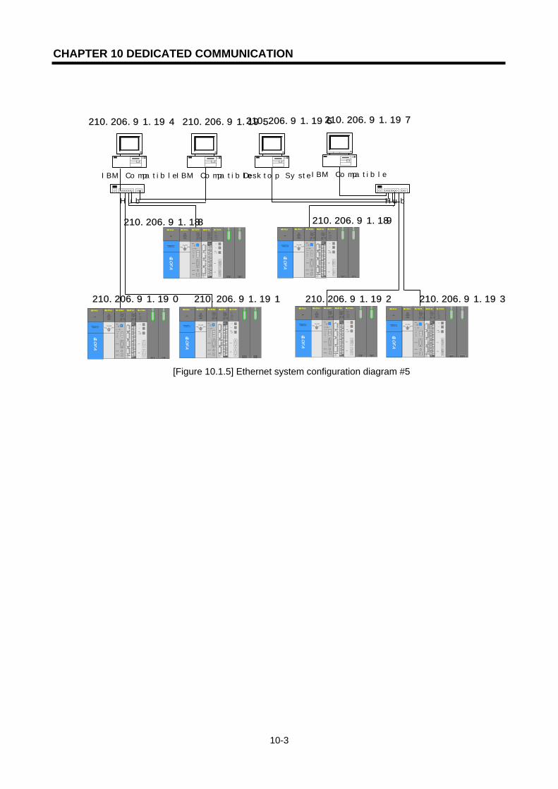
CHAPTER 10 DEDICATED COMMUNICATION
10-3
[Figure 10.1.5] Ethernet system configuration diagram #5
210.206.91.190 210.206.91.193
Desktop System
Hub
G3Q-RY4ARUNCPU I/F RUNFB-SERVECEHS-SERVICEGMWIN-SERVICEGLOFA-SERVICEFTP-SERVICEH/W-ERROR
10BASE5 ENABLE10BASE2 ENABLE10BASE-T LINK10BASE-T PLRTYTXRX
L00
01
02
03
04
05
06
07
COM
L16
17
18
19
04
21
22
23
COM
08L 09
1011
1213
14
15
COM
08L 25
26
27
2829
30
31COM
+- DC24V
RELAYAC250V 2ADC24V 2A
PROGRAMMABLECONTROLLER
GLO
FA
GM3-PA1A
PWR
G3L-EUEA
RUNCPU I/F RUNFB-SERVECEHS-SERVICEGMWIN-SERVICEGLOFA-SERVICEFTP-SERVICEH/W-ERROR
10BASE5 ENABLE10BASE2 ENABLE10BASE-T LINK10BASE-T PLRTYTXRX
MODE
1
234
5
06
7 8 9
0: ON.RUN1: TEST12: TEST2
EXT.POWER
DC IN
+12V
12G
FG
10BASE5
10BASE2
10BASE-T
RUN
GM1-CPUA
RUNSTOP
REMOTEFAIL
ERROR
PAU/REM
STOP
G3L-FUEA
MODE
0: ON.RUN1: TEST12: TEST2
X1
X10
CON1
CON2
1
2345
06
7 89
1
2345
06
7 89
1
2345
06
7 89
RUN
LAS
TOKEN
TX/RX
FAULT
Hub
G3Q-RY4ARUNCPU I/F RUNFB-SERVECEHS-SERVICEGMWIN-SERVICEGLOFA-SERVICEFTP-SERVICEH/W-ERROR
10BASE5 ENABLE10BASE2 ENABLE10BASE-T LINK10BASE-T PLRTYTXRX
L00
01
02
03
04
05
06
07
COM
L16
17
18
19
04
21
22
23
COM
08L 09
1011
1213
14
15
COM
08L25
26
27
2829
30
31COM
+- DC24V
RELAYAC250V 2ADC24V 2A
PROGRAMMABLECONTROLLER
GLO
FA
GM3-PA1A
PWR
G3L-EUEA
RUNCPU I/F RUNFB-SERVECEHS-SERVICEGMWIN-SERVICEGLOFA-SERVICEFTP-SERVICEH/W-ERROR
10BASE5 ENABLE10BASE2 ENABLE10BASE-T LINK10BASE-T PLRTYTXRX
MODE
1
234
5
06
7 89
0: ON.RUN1: TEST12: TEST2
EXT.POWER
DC IN
+12V
12G
FG
10BASE5
10BASE2
10BASE-T
RUN
GM1-CPUA
RUNSTOP
REMOTEFAIL
ERROR
PAU/REM
STOP
G3L-FUEA
MODE
0: ON.RUN1: TEST12: TEST2
X1
X10
CON1
CON2
1
2345
06
7 89
1
234
5
06
7 89
1
2345
06
7 89
RUN
LAS
TOKEN
TX/RX
FAULT
G3Q-RY4ARUNCPU I/F RUNFB-SERVECEHS-SERVICEGMWIN-SERVICEGLOFA-SERVICEFTP-SERVICEH/W-ERROR
10BASE5 ENABLE10BASE2 ENABLE10BASE-T LINK10BASE-T PLRTYTXRX
L00
01
0203
04
05
06
07
COM
L16
17
18
19
04
21
22
23
COM
08L 09
1011
1213
14
15
COM
08L 25
2627
2829
30
31
COM
+- DC24V
RELAYAC250V 2ADC24V 2A
PROGRAMMABLECONTROLLER
GLO
FA
GM3-PA1A
PWR
G3L-EUEA
RUNCPU I/F RUNFB-SERVECEHS-SERVICEGMWIN-SERVICEGLOFA-SERVICEFTP-SERVICEH/W-ERROR
10BASE5 ENABLE10BASE2 ENABLE10BASE-T LINK10BASE-T PLRTYTXRX
MODE
1
2345
06
7 89
0: ON.RUN1: TEST12: TEST2
EXT.POWER
DC IN
+12V
12G
FG
10BASE5
10BASE2
10BASE-T
RUN
GM1-CPUA
RUNSTOP
REMOTEFAIL
ERROR
PAU/REM
STOP
G3L-FUEA
MODE
0: ON.RUN1: TEST12: TEST2
X1
X10
CON1
CON2
1
234
5
06
7 8 9
1
234
5
06
7 8 9
1
234
5
06
7 89
RUN
LAS
TOKEN
TX/RX
FAULT
G3Q-RY4ARUNCPU I/F RUNFB-SERVECEHS-SERVICEGMWIN-SERVICEGLOFA-SERVICEFTP-SERVICEH/W-ERROR
10BASE5 ENABLE10BASE2 ENABLE10BASE-T LINK10BASE-T PLRTYTXRX
L00
01
0203
04
05
06
07
COM
L16
17
18
19
04
21
22
23
COM
08L 09
1011
1213
14
15
COM
08L 25
2627
28
29
30
31
COM
+- DC24V
RELAYAC250V 2ADC24V 2A
PROGRAMMABLECONTROLLER
GLO
FA
GM3-PA1A
PWR
G3L-EUEA
RUNCPU I/F RUNFB-SERVECEHS-SERVICEGMWIN-SERVICEGLOFA-SERVICEFTP-SERVICEH/W-ERROR
10BASE5 ENABLE10BASE2 ENABLE10BASE-T LINK10BASE-T PLRTYTXRX
MODE
1
2345
06
7 8 9
0: ON.RUN1: TEST12: TEST2
EXT.POWER
DC IN
+12V
12G
FG
10BASE5
10BASE2
10BASE-T
RUN
GM1-CPUA
RUNSTOP
REMOTEFAIL
ERROR
PAU/REM
STOP
G3L-FUEA
MODE
0: ON.RUN1: TEST12: TEST2
X1
X10
CON1
CON2
1
234
5
06
7 8 9
1
234
5
06
7 8 9
1
2345
06
7 89
RUN
LAS
TOKEN
TX/RX
FAULT
210.206.91.191 210.206.91.192
IBM Compatible
G3Q-RY4ARUNCPU I/F RUNFB-SERVECEHS-SERVICEGMWIN-SERVICEGLOFA-SERVICEFTP-SERVICEH/W-ERROR
10BASE5 ENABLE10BASE2 ENABLE10BASE-T LINK10BASE-T PLRTYTXRX
L00
01
02
03
04
05
06
07
COM
L16
17
18
19
04
21
22
23
COM
08L 09
1011
1213
14
15
COM
08L 25
26
27
2829
30
31COM
+- DC24V
RELAYAC250V 2ADC24V 2A
PROGRAMMABLECONTROLLER
GLO
FA
GM3-PA1A
PWR
G3L-EUEA
RUNCPU I/F RUNFB-SERVECEHS-SERVICEGMWIN-SERVICEGLOFA-SERVICEFTP-SERVICEH/W-ERROR
10BASE5 ENABLE10BASE2 ENABLE10BASE-T LINK10BASE-T PLRTYTXRX
MODE
1
234
5
06
7 89
0: ON.RUN1: TEST12: TEST2
EXT.POWER
DC IN
+12V
12G
FG
10BASE5
10BASE2
10BASE-T
RUN
GM1-CPUA
RUNSTOP
REMOTEFAIL
ERROR
PAU/REM
STOP
G3L-FUEA
MODE
0: ON.RUN1: TEST12: TEST2
X1
X10
CON1
CON2
1
2345
06
7 89
1
2345
06
7 89
1
234
5
06
7 89
RUN
LAS
TOKEN
TX/RX
FAULT
G3Q-RY4A
RUNCPU I/F RUNFB-SERVECEHS-SERVICEGMWIN-SERVICEGLOFA-SERVICEFTP-SERVICEH/W-ERROR
10BASE5 ENABLE10BASE2 ENABLE10BASE-T LINK10BASE-T PLRTYTXRX
L00
01
0203
04
05
06
07
COM
L16
17
18
19
04
21
22
23
COM
08L 09
1011
1213
14
15
COM
08L25
2627
28
29
30
31
COM
+- DC24V
RELAYAC250V 2ADC24V 2A
PROGRAMMABLECONTROLLER
GLO
FA
GM3-PA1A
PWR
G3L-EUEA
RUNCPU I/F RUNFB-SERVECEHS-SERVICEGMWIN-SERVICEGLOFA-SERVICEFTP-SERVICEH/W-ERROR
10BASE5 ENABLE10BASE2 ENABLE10BASE-T LINK10BASE-T PLRTYTXRX
MODE
1
2345
06
7 89
0: ON.RUN1: TEST12: TEST2
EXT.POWER
DC IN
+12V
12G
FG
10BASE5
10BASE2
10BASE-T
RUN
GM1-CPUA
RUNSTOP
REMOTEFAIL
ERROR
PAU/REM
STOP
G3L-FUEA
MODE
0: ON.RUN1: TEST12: TEST2
X1
X10
CON1
CON2
1
2345
06
7 8 9
1
234
5
06
7 8 9
1
234
5
06
7 89
RUN
LAS
TOKEN
TX/RX
FAULT
210.206.91.188 210.206.91.189
IBM CompatibleIBM Compatible
210.206.91.194 210.206.91.195 210.206.91.196 210.206.91.197

CHAPTER 10 DEDICATED COMMUNICATION
10-4
10.2 Dedicated Communication
10.2.1 Overview
Dedicated communication service is an embedded protocol in the FEnet I/F module that allows the user to read and write PLC information by PC or other devices. It also allows the user to download/upload the PLC program and control the PLC (Run, Stop, Pause). This is accomplished communication by using the TCP port 2004 and the UDP port 2005 of the FEnet I/F module. It is especially useful for between LGIS Ethernet modules, and between high a system (PC program, HMI) and a LGIS Ethernet module.
1) Frame editor basic setting
[Figure 10.2.1] Initial screen for setting the basic parameter
For Ethernet communication, it is required to set the basic download parameters before using. In order to communicate by using the dedicated service, it is required to set the basic download parameters. The dedicated contact number in the basic parameter of the frame editor means the channel number (HMI connection) is arranged by using the dedicated port (2004) of LGIS. Accordingly, it is possible to change the channel contact number for LGIS dedicated communication by converting the dedicated contact number in frame editor. For further information, please refer to [5.2 Frame editor].

CHAPTER 10 DEDICATED COMMUNICATION
10-5
10.2.2 Frame structure
The following shows the application frame structure of the LGIS Ethernet module.
Header IP Header TCP Header
Application Data Format Application Header Format Application Instruction Format
1) Header structure (Application Header Format)
Items Size(byte) Description
Company ID 10 “LGIS-GLOFA” (ASCII CODE: 4C 47 49 53 2D 47 4C 4F 46 41)
PLC Info 2
* Client(HMI) Server(PLC): Irrelevant (0x00) * Server(HMI) Client(PLC): Bit00~05: CPU TYPE 0 (GM1), 1 (GM2), 2 (GM3), 3 (GM4), 4 (GM5), 8 (GM3 Remote), 9 (GM4 Remote)
Bit06: 0 (Redundant Master / Single) 1 (Redundant Slave)
Bit07: 0 (CPU operation normal) 1 (CPU operation error)
Bit08~12: system state 2 (STOP), 4 (RUN), 8 (PAUSE), 10 (DEBUG) Bit13~15: slot no. of the FEnet I/F module
Reserved 1 0x00: reserved area
Source of Frame 1 * Client (HMI) Server (PLC): 0x33 * Server (PLC) Client (HMI): 0x11
Invoke ID 2 ID to distinguish the order between Frames (send by adding this ID to the response frame)
Length 2 byte size of the Application Instruction Reserved 1 0x00: reserved area
Reserved (BCC) 1 0x00: reserved area
(Byte sum of the Application Header)
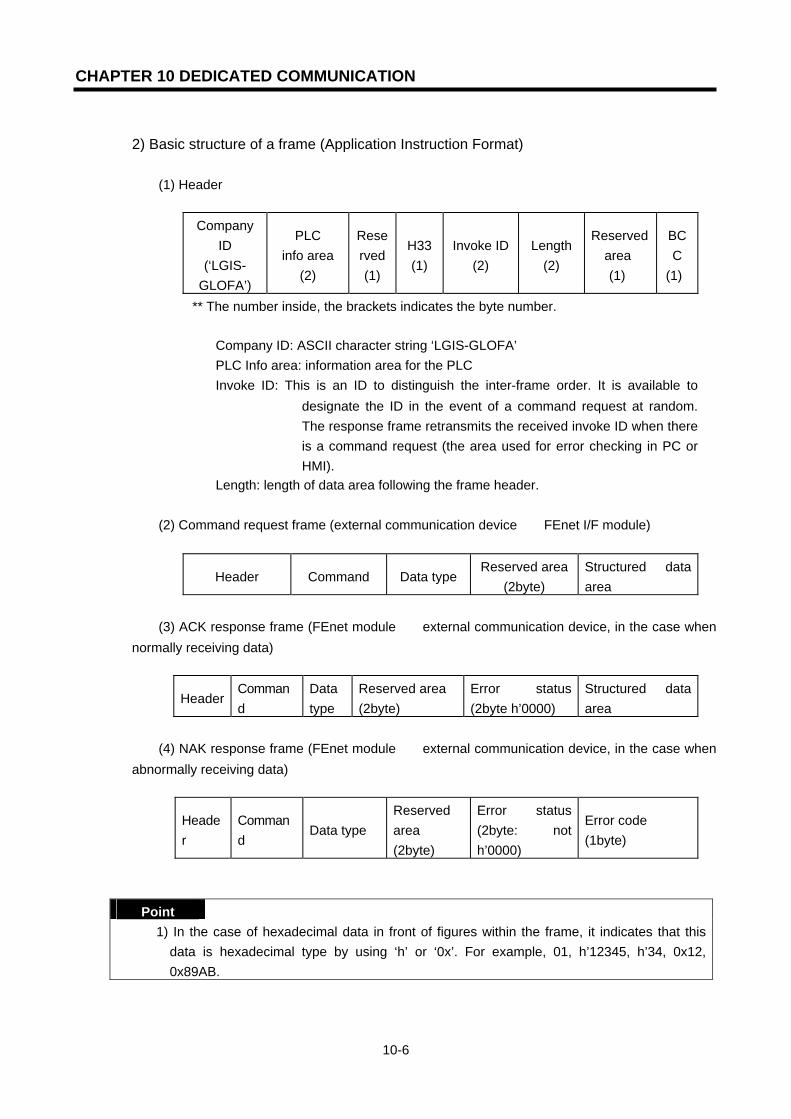
CHAPTER 10 DEDICATED COMMUNICATION
10-6
2) Basic structure of a frame (Application Instruction Format)
(1) Header
Company
ID (‘LGIS-
GLOFA’)
PLC info area
(2)
Reserved (1)
H33(1)
Invoke ID(2)
Length (2)
Reserved area (1)
BCC
(1)
** The number inside, the brackets indicates the byte number.
▷ Company ID: ASCII character string ‘LGIS-GLOFA’ ▷ PLC Info area: information area for the PLC ▷ Invoke ID: This is an ID to distinguish the inter-frame order. It is available to
designate the ID in the event of a command request at random. The response frame retransmits the received invoke ID when there is a command request (the area used for error checking in PC or HMI).
▷ Length: length of data area following the frame header.
(2) Command request frame (external communication device → FEnet I/F module)
Header Command Data type Reserved area
(2byte) Structured data area
(3) ACK response frame (FEnet module → external communication device, in the case when
normally receiving data)
Header Command
Data type
Reserved area (2byte)
Error status (2byte h’0000)
Structured data area
(4) NAK response frame (FEnet module → external communication device, in the case when
abnormally receiving data)
Header
Command
Data type Reserved area (2byte)
Error status (2byte: not h’0000)
Error code (1byte)
Point 1) In the case of hexadecimal data in front of figures within the frame, it indicates that this
data is hexadecimal type by using ‘h’ or ‘0x’. For example, 01, h’12345, h’34, 0x12, 0x89AB.

CHAPTER 10 DEDICATED COMMUNICATION
10-7
10.2.3 Command list The commands used in the dedicated communication service are shown in the Table below.
Command Command
code Data type
Action
Individual
Reads the data according to the data type of the Direct Variables. These data types include Bit, Byte Word, Dword, Lword type or Named variables (the named variables to read should be registered in the Access variable area).
ContinuousReads byte type Direct Variables by block unit (max. 1,400 byte).
Read
Request : h’0054 Response : h’0055
Array Reads the Array Named variables data. (to read the named variables they should be registered in the Access variable area).
Individual
Writes the data according to the data type of the Direct Variables. These data types include Bit, Byte Word, Dword, Lword type or Named variables. (to write the named variables, they should be registered in the Access variable area).
ContinuousWrites byte type Direct Variables by block unit (max. 1,400 byte).
Write
Request : h’0058 Response : h’0059
Array Writes the data of array Named variables. (to write named variables, they should be registered in the Access variable area).
[Table 10.2.1] Command list 10.2.4 Data types
When reading or writing direct. Named variables, caution should be taken for the data type of the direct or named variables desired to read.
1) Data types for the Direct Variables Type of memory device for the GLOFA PLC: M (internal memory), Q (output), I (input), Types of memory device type for the MASTER-K PLC: P, M, L, K, C, D, T, S, F The Data type of the Direct Variables is indicated next to the Direct Variable indicated by the symbol ‘%’.
Data type Used example. Bit %MX0,%QX0.0.0 %IX0.0.0 ,%PX0,%LX0,%FX0
Byte %MB10,%QB0.0.0 %IB0.0.0 Word %MW10,%QW0.0.0 %IW0.0.0,%PW0,%LW0,%FW0,%DW0
Double Word %MD10,%QD0.0.0 %ID0.0.0 Long Word %ML10,%QL0.0.0 %IL0.0.0 (only GM1/2 available)
[Table 10.2.2] List of the data types for the Direct Variable
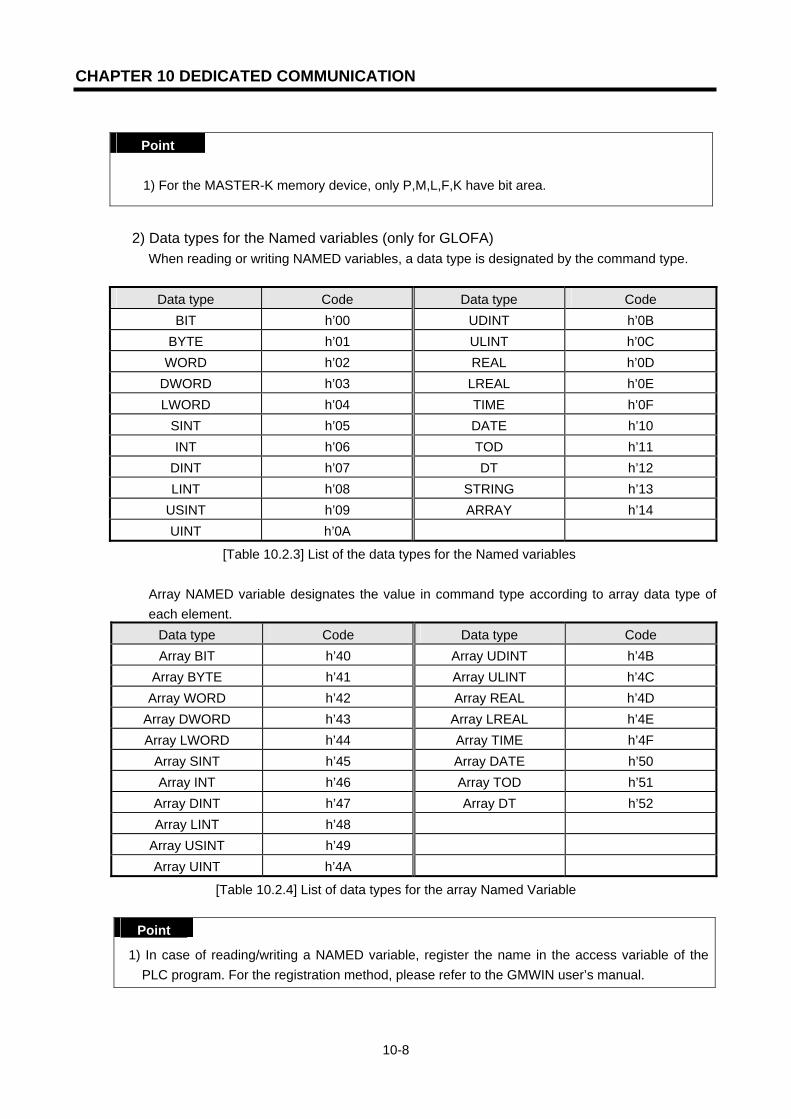
CHAPTER 10 DEDICATED COMMUNICATION
10-8
Point
1) For the MASTER-K memory device, only P,M,L,F,K have bit area.
2) Data types for the Named variables (only for GLOFA)
When reading or writing NAMED variables, a data type is designated by the command type.
Data type Code Data type Code BIT h’00 UDINT h’0B
BYTE h’01 ULINT h’0C WORD h’02 REAL h’0D
DWORD h’03 LREAL h’0E LWORD h’04 TIME h’0F
SINT h’05 DATE h’10 INT h’06 TOD h’11
DINT h’07 DT h’12 LINT h’08 STRING h’13
USINT h’09 ARRAY h’14 UINT h’0A
[Table 10.2.3] List of the data types for the Named variables
Array NAMED variable designates the value in command type according to array data type of each element.
Data type Code Data type Code Array BIT h’40 Array UDINT h’4B
Array BYTE h’41 Array ULINT h’4C Array WORD h’42 Array REAL h’4D
Array DWORD h’43 Array LREAL h’4E Array LWORD h’44 Array TIME h’4F
Array SINT h’45 Array DATE h’50 Array INT h’46 Array TOD h’51
Array DINT h’47 Array DT h’52 Array LINT h’48
Array USINT h’49 Array UINT h’4A
[Table 10.2.4] List of data types for the array Named Variable
Point
1) In case of reading/writing a NAMED variable, register the name in the access variable of the PLC program. For the registration method, please refer to the GMWIN user’s manual.
CHAPTER 10 DEDICATED COMMUNICATION
10-9
10.3 Command Execution
10.3.1 Individual reading of Direct Variable
1) Overview This function directly designates the PLC device memory and reads it according to the memory data type. It is possible to read 16 independent device memories at one time.
2) Request format (PC -> PLC) request for individual variable reading (HMI PLC) Items Size (byte) Description
Command 2 0x0054: Read Request Data type 2 Refer to Data Type Table
Reserved area 2 0x0000: Don’t Care. Number of variables
2 Max. variable number desired to read: max. 16 Variables
Variable name length
2 Variable name length.: max. 16 letters.
Variable Variable
name length Variable name. Direct Variable, access variable available.
... ... (Repeat the procedure for other variable numbers/max. 16) Variable name
length 2 Variable name length. max. 16 letters.
Variable Variable
name length Variable name. Direct Variable, or access variable available.
Format name
HeaderComma
nd Data type
Reserved
area
Block number
Variable length
Direct variable
code (Ex.) h’0054 h’0002 h’0000 h’0001 h’0006 %MW100
...
1 block (repeated setting available up to a max. 16 blocks)
(1) Block number This designates how many blocks composed of ‘[variable length][variable name]’ are there in this request format and how many blocks max. 16 are available for setting. Accordingly, the value of [block number] should be h’0001~ h’0010.
(2) Variable length (Direct Variable name length)
This describes the number of letters of the Direct Variable. A max. of 16 letters are allowed. The range of this value is from h’01 to h’10.

CHAPTER 10 DEDICATED COMMUNICATION
10-10
(3) Direct Variable
The address of the variable that is desired to be read should be entered. It should be an ASCII value within 16 letters. For the variable name, only numbers, small/capital letters, ‘%’, and ‘.’ can be used.
The following table shows the Direct Variable available to use depending on the PLC type. Type Bool Byte Word Double Word Long Word
GM1 %MX,%QX,%IX
%MB,%QB,%IB
%MW,%QW,%IW
%MD,%QD,%ID
%ML,%QL,%IL
GM2 %MX,%QX,%IX
%MB,%QB,%IB
%MW,%QW,%IW
%MD,%QD,%ID
%ML,%QL,%IL
GM3 %MX,%QX,%IX
%MB,%QB,%IB
%MW,%QW,%IW
%MD,%QD,%ID
--
GM4 %MX,%QX,%IX
%MB,%QB,%IB
%MW,%QW,%IW
%MD,%QD,%ID
--
GM6 %MX,%QX,%IX
%MB,%QB,%IB
%MW,%QW,%IW
%MD,%QD,%ID
--
K1000S % (P,M,L,K,F,T)X
-- % (P,M,L,K,F,T,C,D,S)W
-- --
K300S % (P,M,L,K,F,T)X
-- % (P,M,L,K,F,T,C,D,S)W
-- --
K200S % (P,M,L,K,F,T)X
-- % (P,M,L,K,F,T,C,D,S)W
-- --
[Table 10.3.1] Types of Direct Variables
Point
1) For an area designation method for each device of the GLOFA and Master-K series, refer to the GLOFA PLC technical manuals.
2) The device data type of each block should be the same. If the data type of the first block is Word and the data type of second block is Double Word, an error may occur.
Point
1) When preparing the frame, it is required to delete the ‘H’ in front of the figure and change the position of two bytes when the user describes the hexadecimal word data on the above frame Ex.) H’0054 => 5400.

CHAPTER 10 DEDICATED COMMUNICATION
10-11
3) Response format (in the case of an ACK response in the PLC)
Response of Individual Variable Read (PLC HMI)
Items Size (byte) Description Command 2 0x0055: Read Response Data type 2 refer to the Data Type Table
Reserved area 2 0x0000: Don’t Care Error state 2 If ’0’, normal, if not ‘0’, error
Error inform If the Error State is in error, the low Byte is the error no. Variable number
2
If the Error State is normal, the number of variables are read
Data size 2 Byte Size of data. Data Data size Data are read
... ... (Repeat procedure for other variable numbers/max. 16) Data size 2 Byte Size of data.
Data Data size Data are read
Format name
Header Command Data type
Reserved area
Error state
Block number
Data number
Data
Code (Ex.)
... h’0055 h’0002 h’0000 h’0000 h’0001 h’0002 h’1234
......
1 block (max. 16 blocks)
(1) Data number This means HEX type byte number. This number shall be fixed according to the memory type (X,B,W,D,L) included in the Direct Variable name of the computer request format.
(2) Block number
This designates how many blocks composed of ‘[data number][data]’ are there in this request format. A max. 16 blocks are available for setting. Accordingly, the value of [block number] should be h’0001~ h’0010.
Type Bool Byte Word Double Word Long Word GM1 %MX,%QX,%IX %MB,%QB,%IB %MW,%QW,%IW %MD,%QD,%ID %ML,%QL,%IL
Classification Available Direct Variable Data number (Byte)
Bool (X) %MX,%QX,%IX,% (P,M,L,K,F,T)X 1
(Only lowest bit is effective) Byte (B) %MB,%QB,%IB 1
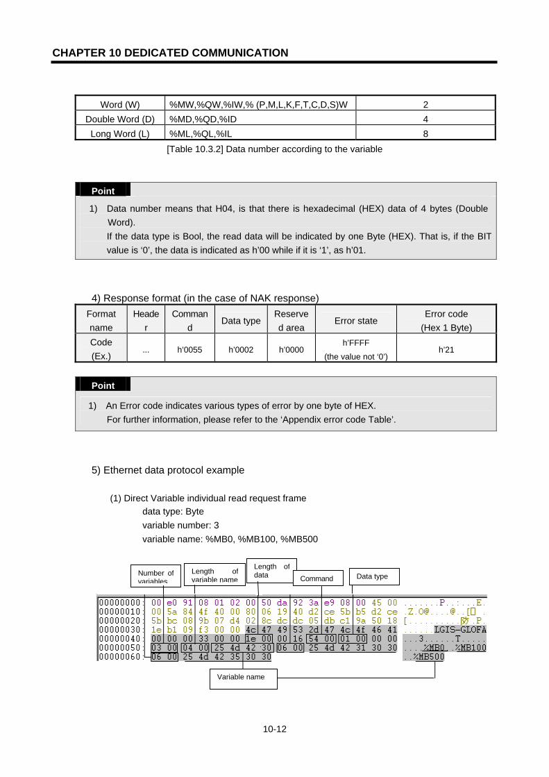
CHAPTER 10 DEDICATED COMMUNICATION
10-12
Word (W) %MW,%QW,%IW,% (P,M,L,K,F,T,C,D,S)W 2
Double Word (D) %MD,%QD,%ID 4 Long Word (L) %ML,%QL,%IL 8
[Table 10.3.2] Data number according to the variable Point
1) Data number means that H04, is that there is hexadecimal (HEX) data of 4 bytes (Double Word). If the data type is Bool, the read data will be indicated by one Byte (HEX). That is, if the BIT value is ‘0’, the data is indicated as h’00 while if it is ‘1’, as h’01.
4) Response format (in the case of NAK response) Format name
Header
Command
Data typeReserved area
Error state Error code
(Hex 1 Byte) Code (Ex.)
... h’0055 h’0002 h’0000 h’FFFF
(the value not ‘0’) h’21
Point
1) An Error code indicates various types of error by one byte of HEX. For further information, please refer to the ‘Appendix error code Table’.
5) Ethernet data protocol example (1) Direct Variable individual read request frame
▷ data type: Byte ▷ variable number: 3 ▷ variable name: %MB0, %MB100, %MB500
Number ofvariables
Length ofvariable name
Length ofdata Command
Variable name
Data type

CHAPTER 10 DEDICATED COMMUNICATION
10-13
(2) Direct Variable individual read response frame
▷ data type: Byte
(3) Direct Variable individual read request frame ▷ data type: Bool-Bit ▷ variable number: 2 ▷ variable name: %MX0, %MX80
(4) Direct Variable individual read response frame ▷ data type: Bool-Bit
PLC INFO 0х1: GM2,Single type,CPU Run 0х84: CPU status-Run, slot position: 4 Length of data Command
Data type
Reservation area
Error Status
No. of Block
Data Length
Data

CHAPTER 10 DEDICATED COMMUNICATION
10-14
10.3.2 Continuous reading of the Direct Variable
1) Overview This designates the PLC device memory directly and continuously reads the data as much as indicated by the designated address. But, only Direct Variables in byte format can be read.
2) Request format (PC ⇒ PLC)
Format name
HeaderComma
nd Data type
Reserved area
Block number
Variable length
Direct variable
Data number
code (Ex.)
... h’0054 h’0014 h’0000 h’0001 h’0006 %MB100 h’0006
Point
1) Data number means the byte number of data (max. 1,400 bytes).
(1) Data type
Data type is available only as h’0014.
(2) Block number Block number is available only as h’0001.
(3) Variable length This is the number of letters for the Direct Variable name. A max. of 16 letters are allowed and the range is from h’0001 to h’0010.
(4) Direct Variable This is the address of the variable to be read. It should be ASCII value within 16 letters. For the variable name, only numbers, small/capital letters, ‘%’ and ’.’ are allowed. The available variable types of the Direct Variable continuous reading are shown in the Table below according to the PLC type.
Classification Byte
GM1 %MB,%QB,%IB GM2 %MB,%QB,%IB GM3 %MB,%QB,%IB GM4 %MB,%QB,%IB GM5 %MB,%QB,%IB
[Table 10.3.3] Variable area for continuous reading
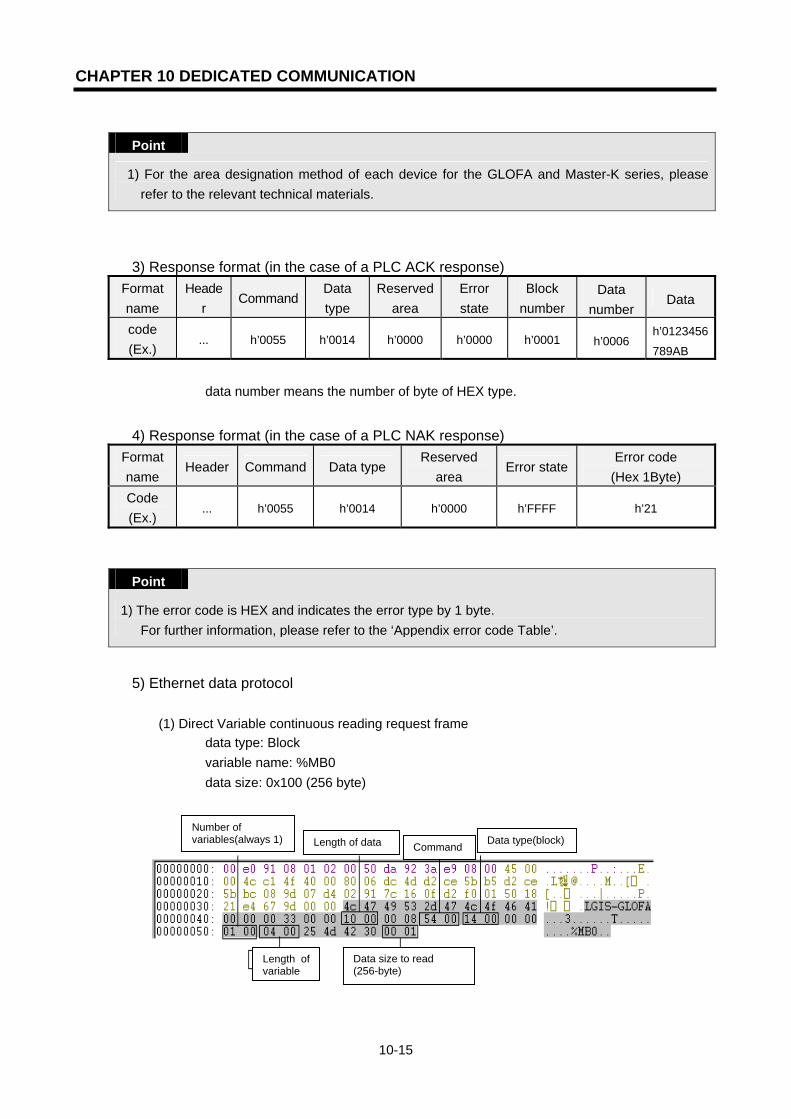
CHAPTER 10 DEDICATED COMMUNICATION
10-15
Point
1) For the area designation method of each device for the GLOFA and Master-K series, please refer to the relevant technical materials.
3) Response format (in the case of a PLC ACK response) Format name
Header
Command Data type
Reservedarea
Error state
Block number
Data number
Data
code (Ex.)
... h’0055 h’0014 h’0000 h’0000 h’0001 h’0006 h’0123456
789AB
▷ data number means the number of byte of HEX type.
4) Response format (in the case of a PLC NAK response) Format name
Header Command Data type Reserved
area Error state
Error code (Hex 1Byte)
Code (Ex.)
... h’0055 h’0014 h’0000 h’FFFF h’21
Point
1) The error code is HEX and indicates the error type by 1 byte. For further information, please refer to the ‘Appendix error code Table’.
5) Ethernet data protocol (1) Direct Variable continuous reading request frame
▷ data type: Block ▷ variable name: %MB0 ▷ data size: 0x100 (256 byte)
Number of variables(always 1)
Length of variable
Data size to read (256-byte)
Length of data Command Data type(block)

CHAPTER 10 DEDICATED COMMUNICATION
10-16
(2) Direct Variable continuous read response frame
▷ data type: Block
10.3.3 Reading of NAMED Variable
1) Overview This registers the variable name in the PLC program access variable and reads the data by using the registered name. For the variable registration method, please refer to the FEnet user’s manual.
2) Request format (PC ⇒ PLC)
in case of the individual type
Format name
Header Command Data type
Reserved area
Block number
Variable length
Variable name
code (Ex.)
... h’0054 h’0002 h’0000 h’0001 h’08 OUTPUT_
1
...
1 block (repeated setting up to max. 16 blocks)
(1) Block number This designates how many blocks composed of ‘[variable length][variable name]’ are there in the request format. A max. 16 blocks are available for setting. Accordingly, the value of the [block number] should be h’0001~ h’0010.
Data size

CHAPTER 10 DEDICATED COMMUNICATION
10-17
in case of array type (block number should be ‘1’)
Format name
Header Command Data type
Reserved area
Block number
Variable length
Variable name
Data number
code (Ex.)
... h’0054 h’004
2 h’0000 h’0001 h’000A
OUTPUT_A
RR h’0004
(2) Variable length
This describes the number of letters in the variable name registered in the PLC access variable. A max. 16 letters are allowed. This value converts the HEX to ASCII using a range from h’01 to h’10.
(3) Variable name
The variable name is read and is an ASCII value within 16 letters. For the variable name, only numbers, small/capital letters, ‘%’, and ‘.’ ‘_’ can be used. The small/capital character are used by distinction but since the PLC access variable name is written in all capitals, it is required to use in CAPITAL letters.
3) Response format (in the case of an ACK response in the PLC) in the case of an individual type
Format name
Header Command Datatype
Reserved area
Errorstate
Block number
Data number
Data ...
Code (Ex.)
... h’0055 h’000
2 h’0000 h’0000 h’OOO1 h’0002 h’1234
1 block (max. 16 block)
in the case of an array type
Format name
Header Command Data type
Reserved area
Error state
Block number
Data number
Data
Code (Ex.)
... h’0055 h’0042 h’0000 h’0000 h’0001 h’OOO2 h’1234
Point
1) Data number: the byte number of data. 2) If the data type is ‘Bool’, the read data shall be indicated by one byte (HEX). That is, if the bit
value is ‘0’, it is indicated by h’00. If the bit value is ‘1’, it is indicated as h’01.
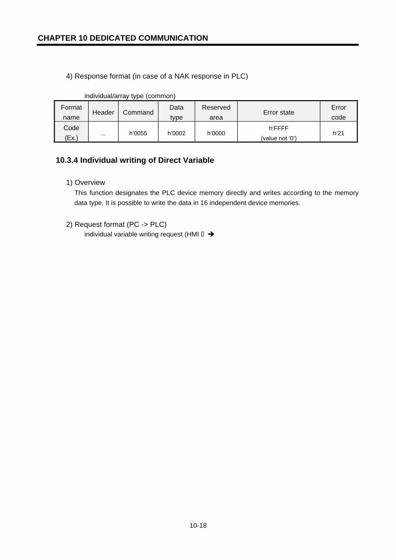
CHAPTER 10 DEDICATED COMMUNICATION
10-18
4) Response format (in case of a NAK response in PLC)
individual/array type (common)
Format name
Header Command Data type
Reserved area
Error state Error code
Code (Ex.)
... h’0055 h’0002 h’0000 h’FFFF
(value not ‘0’) h’21
10.3.4 Individual writing of Direct Variable
1) Overview This function designates the PLC device memory directly and writes according to the memory data type. It is possible to write the data in 16 independent device memories.
2) Request format (PC -> PLC) individual variable writing request (HMI PLC)
Items Size (byte) Description Command 2 0x0058: Write Request Data type 2 Refer to Data Type Table
Reserved area 2 0x0000: Don’t Care.
Variable number 2 Variable number desired to write. max. 16.
Variable name length
2 Variable name length. max. 16 letters.
Variable name Variable
name length Variable name.
... ... (Repeated as much as variable number/max.16) Variable name
length 2 Variable name length. max. 16 letters.
Variable name Variable
name length Variable name. Direct Variable, access variable are available to use.
Data size 2 Byte Size of data. Data Data size Data to write.
... ... (Repeated as much as variable number/max.16) Data size 2 Byte Size of data.
Data Data size Data to write.

CHAPTER 10 DEDICATED COMMUNICATION
10-19
format name
header com-mand
data type
reservedarea
block num-ber
variable length
direct variable
data number
data
code (Ex.)
.. h’0058 h’0002 h’0000 h’0001 h’0006 %MW100
..
h’0002 h’1234
.
.
1 block (repeated setting available up to max. 16 blocks)
(1) Block number This designates how many blocks composed of ‘[variable length][Direct Variable]’ and ‘[data length][data]’ there are in the request format. It is possible to set a max. 16 blocks. Accordingly, the value of the [block number] should be h’01~ h’10.
(2) Variable length (Direct Variable name length) This describes the letter number of Direct Variables. A max. of 16 letters are allowed. The range of value is from h’01 to h’10.
(3) Direct Variable The address of variables desired to write should be entered. It should be an ASCII value within 16 letters. For the variable name, only numbers, small/capital letters, ‘%’, and ’.’ are allowed. For Direct Variable available according to the PLC type, please refer to the data number according to [Table 10.3.2].
Point
1) The device data type of each block should be the same. If the data type of the first block is Word and the data type of the second block is Double Word, an error may occur.
2) For the area designation method of each device of the GLOFA and MK series, refer to the relevant technical manuals.
3) If the data type is Bool, the data is HEX and is indicated by one byte. That is, if the BIT value is ‘0’, it is indicated by h’00. If the BIT value is ‘1’, it is indicated by h’01.
3) Response format (in the case of an ACK response in the PLC)
Format name
Header Command Data type Reserved
area Error state
Block number
Code (Ex.) ... h’0059 h’0002 h’0000 h’0000 h’0001
(1) Block number
This is the block number normally written.

CHAPTER 10 DEDICATED COMMUNICATION
10-20
4) Response format (in the case of a NAK response)
Format name
Header CommandData type
Reserved
area Error state
Error code (Hex 1 Byte)
code (Ex.) ... h’0059 h’0002 h’0000 h’FFFF
(the value not ‘0’) h’21
Point
1) The error code is HEX and indicates the error type by one byte content. For further information, please refer to the ‘APPENDIX error code’.
5) Ethernet data protocol example
(1) Direct Variable individual writing request frame ▷ data type: Byte ▷ variable number: 3 ▷ data: 0x1122, 0x3344, 0x5566 ▷ variable name: %MB0, %MB100, %MB500 From the following protocol, the data type is 0x0002 and set by word type. Accordingly, it may receive the error, but it is required to change the data type to byte (0x0001) to receive the data.
(2) Direct Variable individual writing response frame
▷ error
Number of variables
Data
Byte type
Length of variable name
Variable name
Length of data
Word type
Error status Error code
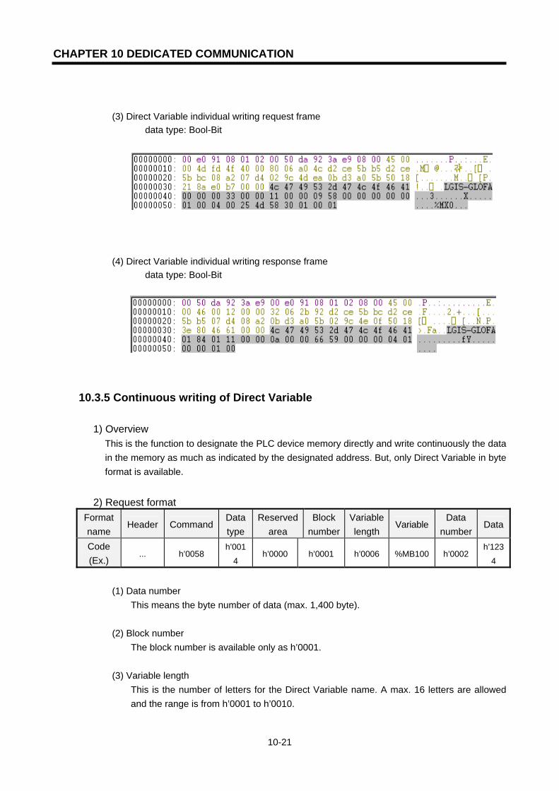
CHAPTER 10 DEDICATED COMMUNICATION
10-21
(3) Direct Variable individual writing request frame ▷ data type: Bool-Bit
(4) Direct Variable individual writing response frame ▷ data type: Bool-Bit
10.3.5 Continuous writing of Direct Variable
1) Overview This is the function to designate the PLC device memory directly and write continuously the data in the memory as much as indicated by the designated address. But, only Direct Variable in byte format is available.
2) Request format Format name
Header Command Data type
Reserved area
Block number
Variablelength
Variable Data
numberData
Code (Ex.)
... h’0058 h’001
4 h’0000 h’0001 h’0006 %MB100 h’0002
h’123
4
(1) Data number
This means the byte number of data (max. 1,400 byte).
(2) Block number The block number is available only as h’0001.
(3) Variable length This is the number of letters for the Direct Variable name. A max. 16 letters are allowed and the range is from h’0001 to h’0010.
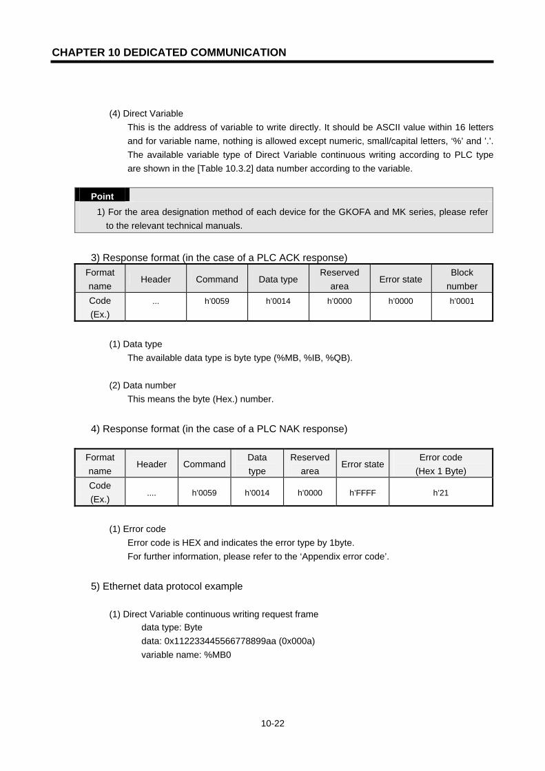
CHAPTER 10 DEDICATED COMMUNICATION
10-22
(4) Direct Variable
This is the address of variable to write directly. It should be ASCII value within 16 letters and for variable name, nothing is allowed except numeric, small/capital letters, ‘%’ and ’.’. The available variable type of Direct Variable continuous writing according to PLC type are shown in the [Table 10.3.2] data number according to the variable.
Point
1) For the area designation method of each device for the GKOFA and MK series, please refer to the relevant technical manuals.
3) Response format (in the case of a PLC ACK response)
Format name
Header Command Data type Reserved
area Error state
Block number
Code (Ex.)
... h’0059 h’0014 h’0000 h’0000 h’0001
(1) Data type
The available data type is byte type (%MB, %IB, %QB).
(2) Data number This means the byte (Hex.) number.
4) Response format (in the case of a PLC NAK response)
Format name
Header CommandData type
Reserved area
Error stateError code
(Hex 1 Byte) Code (Ex.)
.... h’0059 h’0014 h’0000 h’FFFF h’21
(1) Error code
Error code is HEX and indicates the error type by 1byte. For further information, please refer to the ‘Appendix error code’.
5) Ethernet data protocol example
(1) Direct Variable continuous writing request frame ▷ data type: Byte ▷ data: 0x112233445566778899aa (0x000a) ▷ variable name: %MB0

CHAPTER 10 DEDICATED COMMUNICATION
10-23
(2) Direct Variable continuous writing response frame ▷ data type: Byte
10.3.6 Writing of Named Variable
1) Overview This registers the variable name in the PLC program access variable and writes the data by using the registered name. For the variable registration method, please refer to the Fnet user’s manual.
2) Computer request format in the case of an individual type
Format name
Header
Command
Data type
Reserved area
Block numb
er
Variable
length
Variable
name
Data length
Data
Code (Ex.)
... h’0058 h’0002 h’0000 h’0001 h’0008OUTP
UT_1
...
h’0002 h’1234
...
1 block (repeated setting up to max. 16 blocks)
(1) Block number This designates how many blocks composed of ‘[variable length][variable name]’ there are in the request format. A max. 16 blocks are available for setting. Accordingly, the value of the [block number] should be h’0001~ h’0010.
Length of variable Data size
Data
Command
Number of variablesError status

CHAPTER 10 DEDICATED COMMUNICATION
10-24
in the case of an array type
Format name
Header
Command
Data type
Reserved
area
Block numbe
r
Variable length
Variable name
Data numbe
r Data
Code (Ex.)
... h’0058 h’0042 h’0000 h’0001 h’000AOUTPU
T_ARR h’0004 h’12345678
(1) Block number
Block number used should be h’0001.
(2) Variable length This describes the number of letters in the variable name registered in the PLC access variable. A max. 16 letters are allowed. This value converts the HEX to ASCII with a range from h’01 to h’10.
(3) Variable name
This is the variable name used to write and should be an ASCII value 16 letters. For the variable name, only numbers, small/capital letters, ‘%’ and ‘.’ ‘_’ are allowed. The small/capital character is used for distinction but since the PLC access variable name is written in all capitals, it is required to use capital letters.
3) Response format (in the case of an ACK response in the PLC) in the case of an individual type
Format name
Header Command Data type Reserved
area Error state
Block number
code (Ex.) ... h’0059 h’0002 h’0000 h’0000 h’OOO1
in the case of an array type
Format name
Header Command Data type Reserved
area Error state
Block number
code (Ex.) ... h’0059 h’0042 h’0000 h’0000 h’0001
(1) In the case of an array type, the variable number used should be by h’0001. (2) The data length means the byte number of data. (3) If the data type is ‘Bool’, the read data will be indicated by one byte (HEX.). That is, if the
bit value is ‘0’, it is indicated as h’00. If the BIT value is ‘1’, it is indicated as h’01.
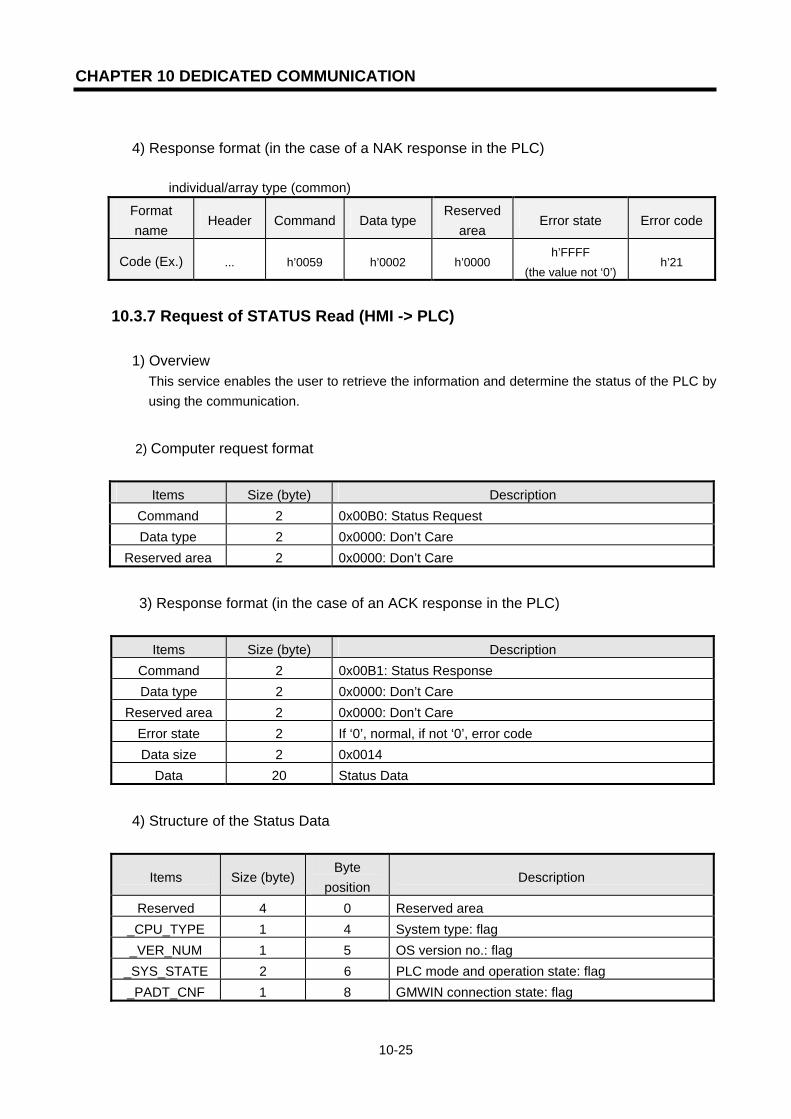
CHAPTER 10 DEDICATED COMMUNICATION
10-25
4) Response format (in the case of a NAK response in the PLC) individual/array type (common)
Format name
Header Command Data type Reserved
area Error state Error code
Code (Ex.) ... h’0059 h’0002 h’0000 h’FFFF
(the value not ‘0’) h’21
10.3.7 Request of STATUS Read (HMI -> PLC)
1) Overview This service enables the user to retrieve the information and determine the status of the PLC by using the communication.
2) Computer request format
Items Size (byte) Description Command 2 0x00B0: Status Request Data type 2 0x0000: Don’t Care
Reserved area 2 0x0000: Don’t Care
3) Response format (in the case of an ACK response in the PLC)
Items Size (byte) Description Command 2 0x00B1: Status Response Data type 2 0x0000: Don’t Care
Reserved area 2 0x0000: Don’t Care Error state 2 If ‘0’, normal, if not ‘0’, error code Data size 2 0x0014
Data 20 Status Data
4) Structure of the Status Data
Items Size (byte) Byte
position Description
Reserved 4 0 Reserved area _CPU_TYPE 1 4 System type: flag _VER_NUM 1 5 OS version no.: flag
_SYS_STATE 2 6 PLC mode and operation state: flag _PADT_CNF 1 8 GMWIN connection state: flag

CHAPTER 10 DEDICATED COMMUNICATION
10-26
_DOMAIN_ST 1 9 System S/W configuration info: flag _CNF_ER 2 10 System error (serious error): flag
_CNF_WAR 2 12 System warning: flag
Slot Info 2 14
Slot information Bit01~Bit03: slot info to indicate that the local is remote connected to another station
Bit05~Bit07: slot info to indicate that another station is remote connected
Bit09~Bit11: slot info that indicate that the module is installed
Reserved 4 16 Reserved area * For further information of each item, please refer to the *flag description.
5) Flag description
_CPU_TYPE (1Byte) GM1 (0x00), GM2 (0x01), GM3 (0x02), GM4 (0x03) GM3_FSM (0x05), GM4_FSM (0x06), SRU (0x07), GMR (0x10) K1000S (0x22), K300S (0x23) K1000S_FSM (0x25), K300S_FSM (0x26)
_VER_NUM (1Byte) BIT0~BIT3: Minor Version indication BIT4~BIT7: Major Version indication Ex.) in the case of indicating v3.1: indicated by 0x31
_SYS_STATE (2Byte)
Position Contents Description
BIT 0 Local control Indicates the state available to change the operation mode only by the mode key or GMWIN/KGLWIN
BIT 1 STOP Indicates the CPU operation state
BIT 2 RUN Indicates the CPU operation state
BIT 3 PAUSE Indicates the CPU operation state
BIT 4 DEBUG Indicates the CPU operation state
BIT 5 Operation mode change
factor Operation mode change by key
BIT 6 Operation mode change
factor Operation mode change by GMWIN/KGLWIN
BIT 7 Operation mode change
factor Operation mode change by remote PADT
BIT 8 Operation mode change
factor Operation mode change by communication

CHAPTER 10 DEDICATED COMMUNICATION
10-27
BIT 9 STOP by STOP function Stop after finishing the scan by using the STOP function during RUN
mode.
BIT 10 Forced input Indicates forced ON/OFF execution for an input contact
BIT 11 Forced output Indicates forced ON/OFF execution for an output contact
BIT 12 STOP by ESTOP
function Emergency stop by the ESTOP function during RUN mode.
BIT 13 Reserved area
BIT 14 Monitor running Indicates that external monitoring is running for the program and variable
BIT 15 Remote mode ON Indicates ‘in operation in remote mode’
_PADT_CNF (1 Byte)
Position Contents Description
BIT 0 Local connection Bit indicating the connection state of the local GMWIN/KGLWIN
BIT 1 Remote connection Bit indicating the connection state of the remote PADT
BIT 2 Remote communication
connection Bit indicating the connection state of the remote communication
BIT 3
~ BIT 7 - Reserved area
_DOMAIN_ST (1Byte)
Position Contents Description
BIT 0 Basic parameter error Flag indicating the error after checking the basic parameter
BIT 1 I/O parameter error Flag indicating the error after checking the I/O configuration parameter
BIT 2 Program error Flag indicating the error after checking the user program
BIT 3 Access variable error Flag indicating the error after checking the access variable
BIT 4 High speed link
parameter error Flag indicating the error after checking the high speed link parameter
BIT 5
~ BIT 7 - Reserved area
_CNF_ER (2Byte)
Position Contents Description
BIT 0 CPU configuration error [_CPU_ER]
Error flag that occurs when normal operation is not possible because of a self diagnosed error of the CPU module/base CPU installation error/multi CPU configuration error etc. (for further information, refer to _SYS_ERR).
BIT 1 Module type mismatch error [_IO_TYER]
Representative flag indicating an error in the case that the I/O configuration parameter of each slot is different from the currently installed module or that the special module is installed in an unusable slot (refer to _IO_TYER_N, _IOTYER[n]).
BIT 2 module delete error [_IO_DEER]
Representative flag indicating an error when the module configuration of each slot is changed during operation (refer to _IO_DEER_N,
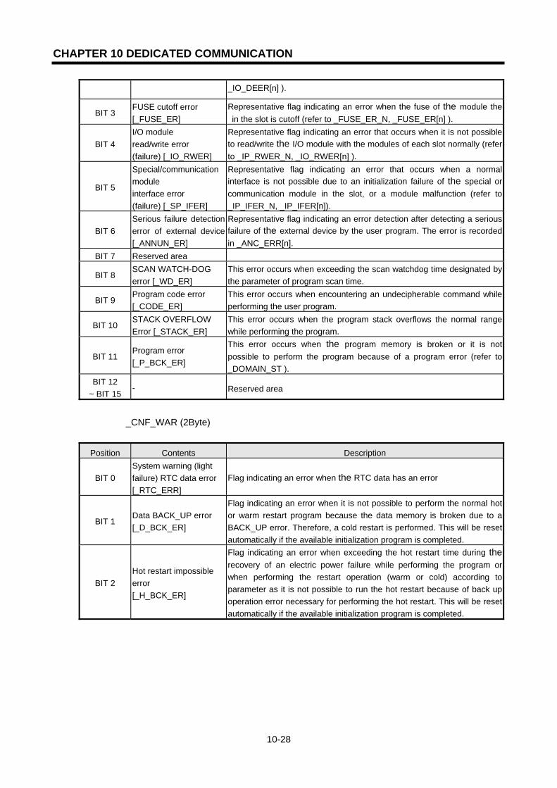
CHAPTER 10 DEDICATED COMMUNICATION
10-28
_IO_DEER[n] ).
BIT 3 FUSE cutoff error [_FUSE_ER]
Representative flag indicating an error when the fuse of the module the in the slot is cutoff (refer to _FUSE_ER_N, _FUSE_ER[n] ).
BIT 4 I/O module read/write error (failure) [_IO_RWER]
Representative flag indicating an error that occurs when it is not possible to read/write the I/O module with the modules of each slot normally (refer to _IP_RWER_N, _IO_RWER[n] ).
BIT 5
Special/communication module interface error (failure) [_SP_IFER]
Representative flag indicating an error that occurs when a normal interface is not possible due to an initialization failure of the special or communication module in the slot, or a module malfunction (refer to _IP_IFER_N, _IP_IFER[n]).
BIT 6 Serious failure detection error of external device [_ANNUN_ER]
Representative flag indicating an error detection after detecting a serious failure of the external device by the user program. The error is recorded in _ANC_ERR[n].
BIT 7 Reserved area
BIT 8 SCAN WATCH-DOG error [_WD_ER]
This error occurs when exceeding the scan watchdog time designated by the parameter of program scan time.
BIT 9 Program code error [_CODE_ER]
This error occurs when encountering an undecipherable command while performing the user program.
BIT 10 STACK OVERFLOW Error [_STACK_ER]
This error occurs when the program stack overflows the normal range while performing the program.
BIT 11 Program error [_P_BCK_ER]
This error occurs when the program memory is broken or it is not possible to perform the program because of a program error (refer to _DOMAIN_ST ).
BIT 12 ~ BIT 15
- Reserved area
_CNF_WAR (2Byte)
Position Contents Description
BIT 0 System warning (light failure) RTC data error [_RTC_ERR]
Flag indicating an error when the RTC data has an error
BIT 1 Data BACK_UP error [_D_BCK_ER]
Flag indicating an error when it is not possible to perform the normal hot or warm restart program because the data memory is broken due to a BACK_UP error. Therefore, a cold restart is performed. This will be reset automatically if the available initialization program is completed.
BIT 2 Hot restart impossible error [_H_BCK_ER]
Flag indicating an error when exceeding the hot restart time during the recovery of an electric power failure while performing the program or when performing the restart operation (warm or cold) according to parameter as it is not possible to run the hot restart because of back up operation error necessary for performing the hot restart. This will be reset automatically if the available initialization program is completed.

CHAPTER 10 DEDICATED COMMUNICATION
10-29
BIT 3
Abnormal operation shutdown (ABNORMAL SHUTDOWN) [_AB_SD_ER]
Flag in the case where a warm restart is performed when power re-input after the program is shutdown in the middle of running due to the power shutdown while performing the program, the operation restarts the program from the beginning which may cause the error in operation of the preserved data area. This is available in the initialization program. Automatic resetting after completion of initialization program. Also indicates the error when program is shutdown in the middle of running by 'ESTOP' function.
BIT 4
TASK crash (regular period, external task) [_TASK_ERR]
Flag indicating a task crash in the case that a repeated execution of the same task is required while performing the user program. (refer to _TC_BMAP[n],_TC_CNT[n])
BIT 5 Battery error [_BAT_ERR]
Flag indicating an error when the battery voltage is less than the specification for the backup of the user program and data memory.
BIT 6 Light failure detection of the external device [_ANNUN_WR]
Representative flag indicating an error when detecting the light failure of the external device by the user program. The error is recovered in _ANC_WB[n].
BIT 7 - Reserved area
BIT 8 High speed link parameter 1 error [_HSPMT1_ER]
BIT 9 High speed link parameter 2 error [_HSPMT2_ER]
BIT 10 High speed link parameter 3 error [_HSPMT3_ER]
BIT 11 High speed link parameter 4 error [_HSPMT4_ER]
Representative flag indicating an error when it is not possible to perform a
high speed link after checking each high speed link parameter error.
Reset when the high speed link is disabled.
BIT 12 ~ BIT 15 - Reserved area

CHAPTER 11 RESETTING THE COMMUNICATION MODULE IN RUN MODE
11-1
CHAPTER 11 RESETTING THE COMMUNICATION MODULE IN RUN MODE
11.1 Overview When the communication by Ethernet does not work smoothly due to a certain obstacle, FEnet I/F module Reset Function clears the relevant communication modules without resetting the whole system. The communication module sends/receives the data through ‘Common RAM’. The module is required to run the system again if the data processing is delayed by some reasons (ex: by packet increase of the system configuration) or if the data sent/received is not good due to abnormal action by the communication module. In the case when power OFF/ON is not possible, this enables the user to perform normal functions by initializing the module during running without rebooting the system.
[Figure 11.1.1] Resetting the communication module during run mode
Point
1) The above function is available only in GM1/2-CPUA(B) and GM4-CPUC. Other models are scheduled to be available later. The available versions are as follows :
(1) GM1/2-CPUB O/S version : more than V3.0 (2) GM4-CPUC O/S version : more than V2.1 (3) GMWIN version : more than V4.04 (4) FEnet I/F module O/S version : more than V1.1
2) The initialization process does not impose a burden on the scan time if it is carried out when system power is turned OFF -> ON. However, if it is processed during running, it may impose a burden on the scan time.
3) The reset of the relevant communication module during running should be performed in limited situations (emergency situations),. Caution should be taken.
Upper System
Flag reset
Remote connection reset
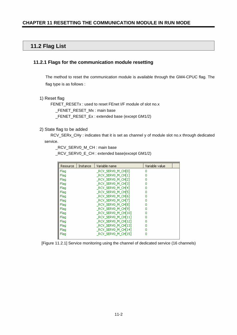
CHAPTER 11 RESETTING THE COMMUNICATION MODULE IN RUN MODE
11-2
11.2 Flag List
11.2.1 Flags for the communication module resetting
The method to reset the communication module is available through the GM4-CPUC flag. The
flag type is as follows :
1) Reset flag FENET_RESETx : used to reset FEnet I/F module of slot no.x
_FENET_RESET_Mx : main base _FENET_RESET_Ex : extended base (except GM1/2)
2) State flag to be added RCV_SERx_CHy : indicates that it is set as channel y of module slot no.x through dedicated service.
_RCV_SERV0_M_CH : main base _RCV_SERV0_E_CH : extended base(except GM1/2)
[Figure 11.2.1] Service monitoring using the channel of dedicated service (16 channels)
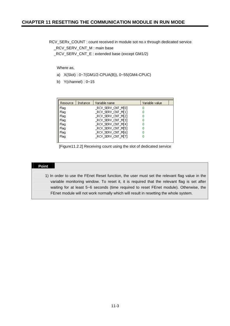
CHAPTER 11 RESETTING THE COMMUNICATION MODULE IN RUN MODE
11-3
RCV_SERx_COUNT : count received in module sot no.x through dedicated service
_RCV_SERV_CNT_M : main base _RCV_SERV_CNT_E : extended base (except GM1/2)
Where as,
a) X(Slot) : 0~7(GM1/2-CPUA(B)), 0~55(GM4-CPUC)
b) Y(channel) : 0~15
[Figure11.2.2] Receiving count using the slot of dedicated service
Point
1) In order to use the FEnet Reset function, the user must set the relevant flag value in the variable monitoring window. To reset it, it is required that the relevant flag is set after waiting for at least 5~6 seconds (time required to reset FEnet module). Otherwise, the FEnet module will not work normally which will result in resetting the whole system.

CHAPTER 11 RESETTING THE COMMUNICATION MODULE IN RUN MODE
11-4
11.3 Reset Program
11.3.1 Forced reset of flag through monitoring
This is the method for a forced reset of the communication module through the GMWIN program monitor without preparing a separate program. It is possible to reset ON/OFF by registering only the monitor variables (_FENET_RESETx). If this value is ‘ON’, the RESET of the FEnet I/F module will be performed. If the RESET is performed normally, the value will be cleared to ‘0’.If it is not cleared, this means that the service has not performed normally. [Figure 11.3.1] shows the procedure to reset the communication module. In order to register the RESET flag, click GMWIN [View]->[variable monitor window].
[Figure 11.3.1] Variable monitor window open
Select the variable list for monitoring. Here, select ‘flag’ and register the desired flag.
[Figure 11.3.2] Flag variable selection
[Figure 11.3.3] shows the flag list to reset the communication module.
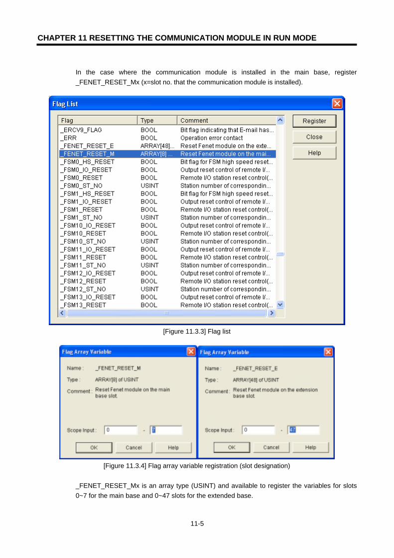
CHAPTER 11 RESETTING THE COMMUNICATION MODULE IN RUN MODE
11-5
In the case where the communication module is installed in the main base, register _FENET_RESET_Mx (x=slot no. that the communication module is installed).
[Figure 11.3.3] Flag list
[Figure 11.3.4] Flag array variable registration (slot designation)
_FENET_RESET_Mx is an array type (USINT) and available to register the variables for slots 0~7 for the main base and 0~47 slots for the extended base.
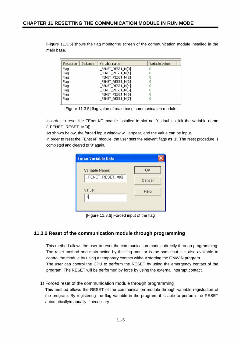
CHAPTER 11 RESETTING THE COMMUNICATION MODULE IN RUN MODE
11-6
[Figure 11.3.5] shows the flag monitoring screen of the communication module installed in the main base.
[Figure 11.3.5] flag value of main base communication module
In order to reset the FEnet I/F module installed in slot no.’0’, double click the variable name (_FENET_RESET_M[0]). As shown below, the forced input window will appear, and the value can be input. In order to reset the FEnet I/F module, the user sets the relevant flags as ‘1’. The reset procedure is completed and cleared to ‘0’ again.
[Figure 11.3.6] Forced input of the flag
11.3.2 Reset of the communication module through programming
This method allows the user to reset the communication module directly through programming. The reset method and main action by the flag monitor is the same but it is also available to control the module by using a temporary contact without starting the GMWIN program. The user can control the CPU to perform the RESET by using the emergency contact of the program. The RESET will be performed by force by using the external interrupt contact.
1) Forced reset of the communication module through programming This method allows the RESET of the communication module through variable registration of the program. By registering the flag variable in the program, it is able to perform the RESET automatically/manually if necessary.

CHAPTER 11 RESETTING THE COMMUNICATION MODULE IN RUN MODE
11-7
[Figure 11.3.7] Shows the programming method using the reset input condition. The RESET flag variable was used as the input contact.
Figure[11.3.7] Programming example for RESET
If the reset condition is triggered through the input condition (RESET_SWx), the flag installed in the relevant slot will be set as ‘1’. In this case, the flag _FENET_RESET_M[x] shall be ON to reset the communication module and then cleared.
Point
1) When setting the RESET flags of the program to ‘1’, the user should use a Positive Transition-sensing Contact (-l P l-) for an input contact (condition). Even in the case of resetting again, check that the input contact (condition) is ON after waiting for 5~6 seconds.
2) When using the input condition by Open Contact (-l l-) instead of Positive Transition-sensing Contact, the communication module repeats the reset command until the contact is reset. In this case, the separate contact reset program is needed.

CHAPTER 12 PROGRAM EXAMPLES
12-1
CHAPTER 12 PROGRAM EXAMPLES
12.1 GMWIN Program 12.1.1 High Speed Link service between FEnet PLCs
The following Ethernet system describes the setting method of the High Speed Link parameter
for data communication with the I/O structure in [Table12.1.1].
[Figure 12.1.1] The I/O configuration and sending/receiving of data
Sending/receiving structure I/O configuration Sending area Receiving area
GM2 TX %IW0.2.0(4Word) - (Station 1) RX: <-- GM3 - %MW0(4 words)
GM3 TX %IW0.2.0(4Word) - (Station 2) RX: <-- GM6 - %MW0(4 words)
GM6 TX %IW0.2.0(4Word) - (Station 3) RX: <-- GM2
Slot 0: FEnet Slot1: output 32point Slot2: input 32point (same configuration of all station)
- %MW0(4 words) [Table 12.1.1] Sending/receiving memory map
From the example, GM2/3/6 CPU sends an input value of 4 words from slot no.2 and saves the received data from the destination station in %MW0. It then outputs by using the output module of slot no.1. For the High Speed Link parameter configuration and the program for data exchange, it is described in [Figure12.1.4] and [Figure12.1.5]. [Figure 12.1.4] shows an example how to move the data saved in %MW0 to %QW0.1.0 by using the High Speed Link sending/receiving monitoring flag.
GM2-CPUA
FEnet dedicated network
Station 1
I/O
POWER
CPU
I/OI/OI/OI/OI/O
G3L-E
UTB
I/O
Station 2
GM3-CPUA
I/O
POWER
CPU I/OI/OI/OI/OI/O
G3L-E
UTB
I/O
Station 3
GM6-CPUA
I/O
POWERCPU
I/OI/OI/OI/OI/O
G3L-E
UTB
I/O

CHAPTER 12 PROGRAM EXAMPLES
12-2
1) Basic setting of Frame Editor
In order to carry out the High Speed Link, the basic settings of Frame Editor must be edited and download. In this example, the PLC type and station no. are set the High Speed Link communication.
[Figure 12.1.2] The basic settings of the Frame Editor screen (Example of the GM2 Station 1)
Point
1) The High Speed Link setting mode can either select extended mode (200 WORD) or the basic mode (60 WORD). GM1/2/3 is set by 200 WORD, GM4C by 200 WORD or 60 WORD; GM4A/B, and GM6 by 60 WORD. This mode describes the max. data size of the High Speed Link that each CPU can support.
2) For further information for Frame Editor, please refer to section 5.2 Frame Editor.

CHAPTER 12 PROGRAM EXAMPLES
12-3
After completing the basic settings, download the relevant frame by the PLC. If ‘download’ is completed, reset the PLC CPU.
[Figure 12.1.3] Writing the Basic parameter
Point
1) For High Speed Link communication, download only the basic settings.
2) User program preparation
[Figure12.1.4] Example of the user program (GM1/2/3 common)
[Figure12.1.4] shows an example of a user program. If the High Speed Link is normal (_HS1RLINK=1, _HS1LTRBL=0), output the received data %MW0 using the output module of slot no.1. If used properly when combined with the program using RUN-LINK, the LINK-TROUBLE information shown in [Figure 12.1.4], may increase the reliability of work. For further information of flag types and their use, please refer to section 6.5 High Speed Link information.
Execute when the High SpeedLink info. is normal. (in the case that RUN-LINK is‘1 and LINK-TROUBLE is ’ ‘0’)

CHAPTER 12 PROGRAM EXAMPLES
12-4
3) Settings the High Speed Link Parameters
For the system in [Figure 12.1.1] and for the data exchange between Stations 1,2,3 like [Table 12.1.1], the user should prepare the user program like [Figure12.1.4] and then prepare the data sending/receiving map like [Table 12.1.1]. For data sending/receiving like [Table 12.1.1], prepare the High Speed Link parameter and download using the PLC. The procedure to start the High Speed Link is as follows:
(1) Download the station no. and parameters (by Frame Editor), connect the communication
cable. (2) Prepare the user program (for each station). (3) Prepare the data sending/receiving map. (4) Set the parameters for the GMWIN High Speed Link parameter settings. (5) Execute compile and make from the compile menu. (6) Execute the program and write the parameter from the online menu. (7) Select the link enable settings from the online menu and enable the High Speed Link
suitable for the setting no. (8) Change the mode to RUN from the online menu. (9) Check the High Speed Link state using the link parameter monitor. (10) If an error occurs, retry from (1).
The High Speed Link parameter for the example system is set by the following method. Select the ‘modify’ button in the link setting from the High Speed Link setting screen in [Figure12.1.5] to set the basic items. In this case, set the module type as GLOFA FEnet and also set the FEnet module installation position and the High Speed Link station no. Select ‘verify’ to complete the High Speed Link settings. After completing the High Speed Link settings, set the sending/receiving parameters from item ‘0’ in the order of the [Figure12.1.5] registration list screen. For the GM2 Station ‘1’ in the example, station type is ‘local’. Since it is composed of a sending 0 block and a receiving 0 block, the parameter is configured for each sending/receiving area. The sending/receiving area is set by the sending/receiving data map and the sending/receiving time is calculated by section ‘6.6 High Speed Link speed calculation’. In this example, it is set as the basic value of 200 . [Figure12.1.5] a, b, c shows the results of the setting parameter in GM2, GM3, GM6.
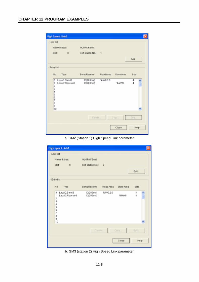
CHAPTER 12 PROGRAM EXAMPLES
12-5
a. GM2 (Station 1) High Speed Link parameter
b. GM3 (station 2) High Speed Link parameter
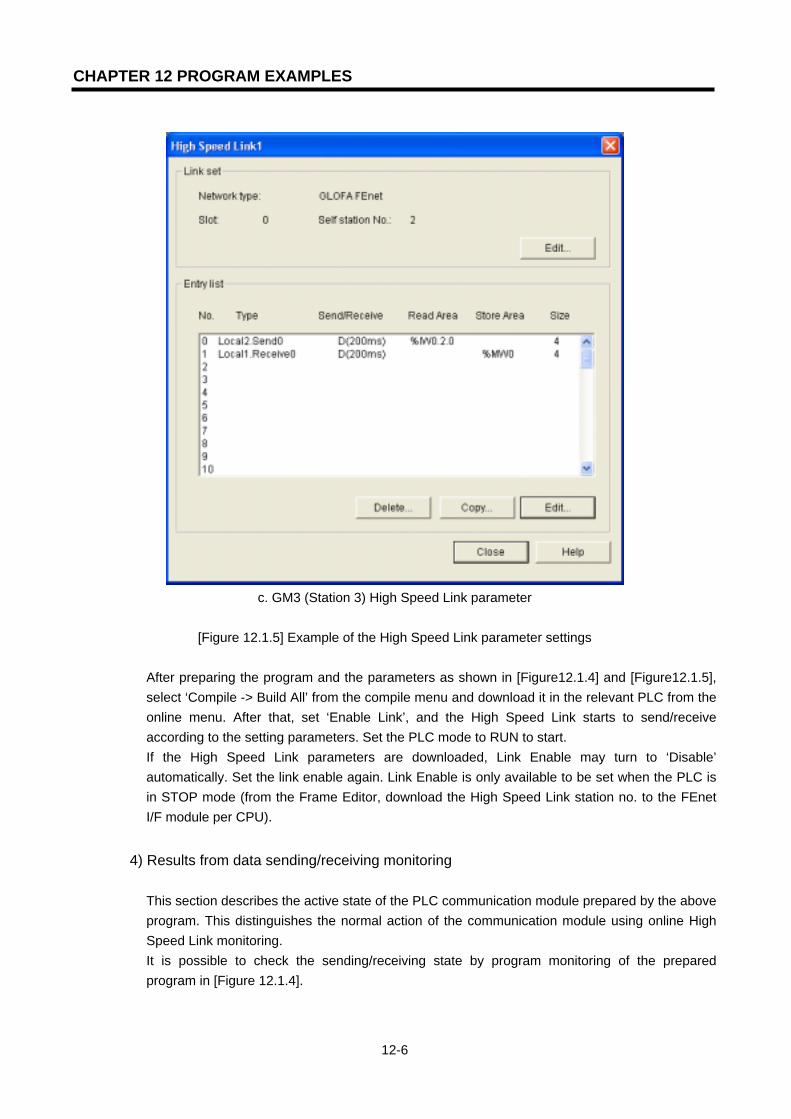
CHAPTER 12 PROGRAM EXAMPLES
12-6
c. GM3 (Station 3) High Speed Link parameter
[Figure 12.1.5] Example of the High Speed Link parameter settings
After preparing the program and the parameters as shown in [Figure12.1.4] and [Figure12.1.5], select ‘Compile -> Build All’ from the compile menu and download it in the relevant PLC from the online menu. After that, set ‘Enable Link’, and the High Speed Link starts to send/receive according to the setting parameters. Set the PLC mode to RUN to start. If the High Speed Link parameters are downloaded, Link Enable may turn to ‘Disable’ automatically. Set the link enable again. Link Enable is only available to be set when the PLC is in STOP mode (from the Frame Editor, download the High Speed Link station no. to the FEnet I/F module per CPU).
4) Results from data sending/receiving monitoring
This section describes the active state of the PLC communication module prepared by the above program. This distinguishes the normal action of the communication module using online High Speed Link monitoring. It is possible to check the sending/receiving state by program monitoring of the prepared program in [Figure 12.1.4].
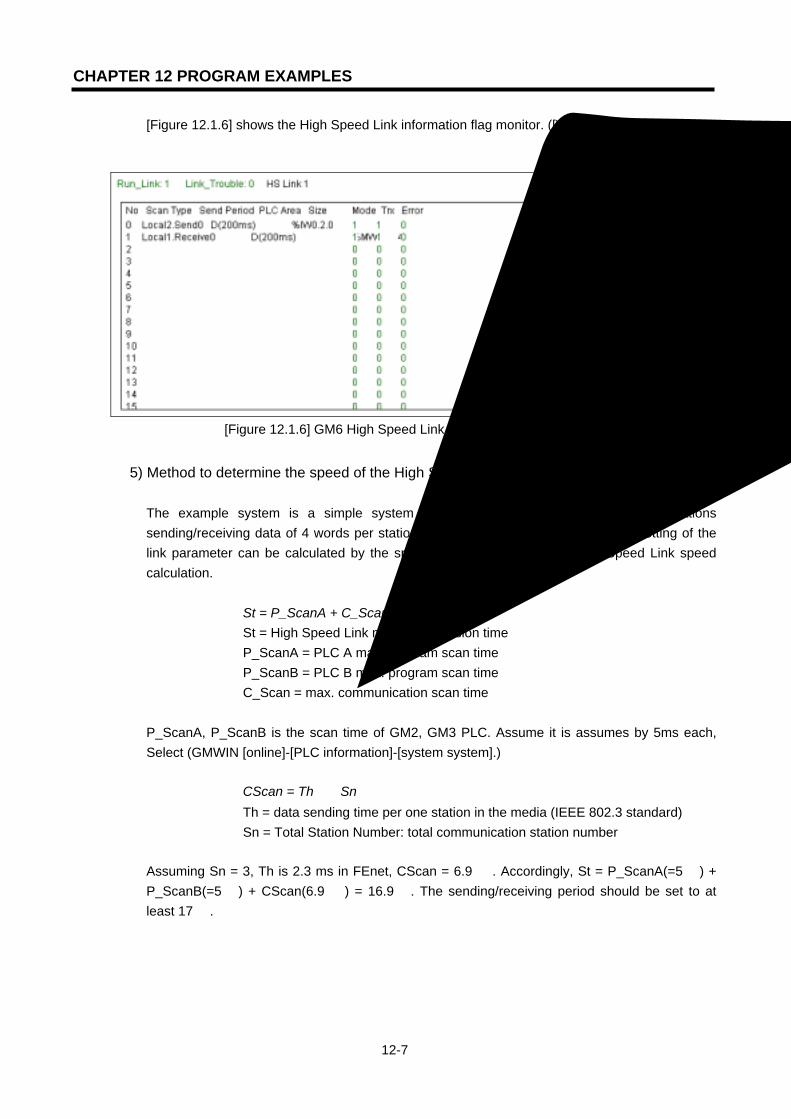
CHAPTER 12 PROGRAM EXAMPLES
12-7
[Figure 12.1.6] shows the High Speed Link information flag monitor. ([View]-[Link parameter])
[Figure 12.1.6] GM6 High Speed Link 1 monitoring screen
5) Method to determine the speed of the High Speed Link
The example system is a simple system with the communication module of 3 stations sending/receiving data of 4 words per station. Thus, the sending/receiving period setting of the link parameter can be calculated by the speed formula in section 6.6 High Speed Link speed calculation.
St = P_ScanA + C_Scan + P_ScanB St = High Speed Link max. transmission time P_ScanA = PLC A max. program scan time P_ScanB = PLC B max. program scan time C_Scan = max. communication scan time
P_ScanA, P_ScanB is the scan time of GM2, GM3 PLC. Assume it is assumes by 5ms each, Select (GMWIN [online]-[PLC information]-[system system].)
CScan = Th × Sn Th = data sending time per one station in the media (IEEE 802.3 standard) Sn = Total Station Number: total communication station number
Assuming Sn = 3, Th is 2.3 ms in FEnet, CScan = 6.9 . Accordingly, St = P_ScanA(=5 ) + P_ScanB(=5 ) + CScan(6.9 ) = 16.9 . The sending/receiving period should be set to at least 17 .

CHAPTER 12 PROGRAM EXAMPLES
12-8
12.1.2 High Speed Link service of redundant CPU and GM3
The following system configuration shows an example to perform the High Speed Link by
communication duplication of a redundancy CPU and GM3 PLC.
[Figure 12.1.7] Network of a redundancy CPU and GM3 PLC
The following table defines the sending/receiving data as follows :
Sending/receiving structure Reading area Saving area Block no.
Sending: 10 words %MW0 - 0 Redundancy CPU (Station 0) Receiving: 59 words - %MW100 1
Sending: 60 wordsA axis: %MW0B axis: %MW0
- 1 GM3 CPU(1station)
Receiving: 11 words - A axis: %MW100 B axis: %MW200
0
[Table 12.1.2] Sending/receiving memory map
1) Working procedure (1) Set the station no. of the communication module (using Frame Editor) and connect the
communication cable. (2) Prepare the user program (per PLC) (3) Prepare the data sending/receiving map (refer to [Table 12.1.2]) (4) Set the parameters from the GMWIN High Speed Link parameter settings. (5) Execute ‘Compile’ and ‘Compile -> Build All’ from the compile menu. (6) Execute the program and write the parameter from the online menu.
Dedicated network1 Ethernet
Single CPU system(GM1/2/3/4)Redundancy CPU system(GMR-CPUA)
165.244.159.108
or 165.244.149.108
165.244.159.109
or 165.244.149.109165.244.149.109
Ethernet Dedicated network2
165.244.149.108
Station 0 Station 0
CP
U-A
CP
U-B
DIFA
PO
WE
I/F
comm
unicom
muni
G3L-
I/FPOWER
comm
unicom
muni
G3L-E
UTB
BA
Station 1
I/O
POWER
CP
U
I/O I/O I/O I/O I/O
Station 1
G3L-E
UTB
G3L-E
UTB
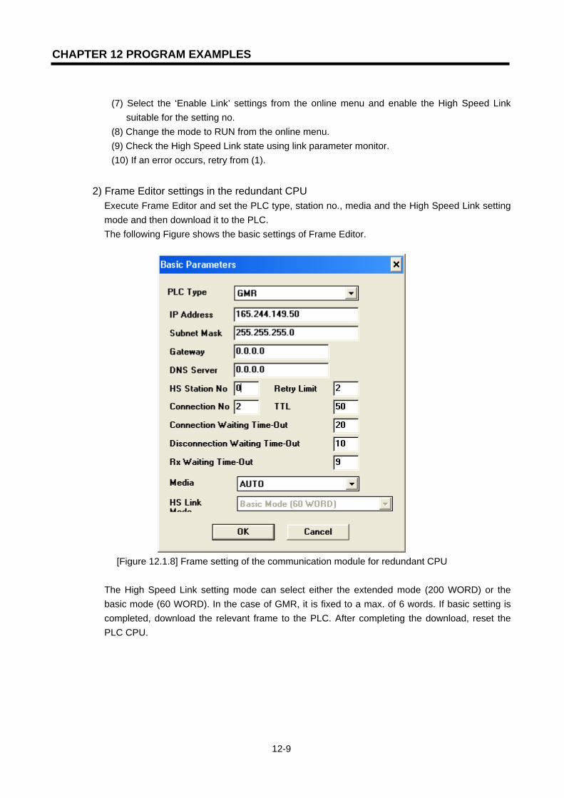
CHAPTER 12 PROGRAM EXAMPLES
12-9
(7) Select the ‘Enable Link’ settings from the online menu and enable the High Speed Link
suitable for the setting no. (8) Change the mode to RUN from the online menu. (9) Check the High Speed Link state using link parameter monitor. (10) If an error occurs, retry from (1).
2) Frame Editor settings in the redundant CPU Execute Frame Editor and set the PLC type, station no., media and the High Speed Link setting mode and then download it to the PLC. The following Figure shows the basic settings of Frame Editor.
[Figure 12.1.8] Frame setting of the communication module for redundant CPU
The High Speed Link setting mode can select either the extended mode (200 WORD) or the basic mode (60 WORD). In the case of GMR, it is fixed to a max. of 6 words. If basic setting is completed, download the relevant frame to the PLC. After completing the download, reset the PLC CPU.

CHAPTER 12 PROGRAM EXAMPLES
12-10
[Figure 12.1.9] Selection of the duplication communication port
In order to connect by Duplication and download the frame to the communication module, select ‘duplication’ for the PLC from the communication port menu in Frame Editor as shown in [Figure12.1.9]. Then connect online and select the CPU type (master/slave) desired to download and download it to the PLC CPU.
[Figure 12.1.10] Redundant CPU selection screen
[Figure 12.1.11] Redundant CPU connection completed

CHAPTER 12 PROGRAM EXAMPLES
12-11
[Figure 12.1.12] Writing the basic parameters
Point
1) For High Speed Link communication, download only the basic settings.
3) Preparation of redundant CPU (GMR-CPUA) program preparation
(1) Select the High Speed Link.
Open the project for duplication or make a new one. Select the High Speed Link parameters from the project. The following screen will be appeared. Select one of the four High Speed Links. In the example, High Speed Link 1 is selected.
[Figure 12.1.13] High Speed Link selection screen
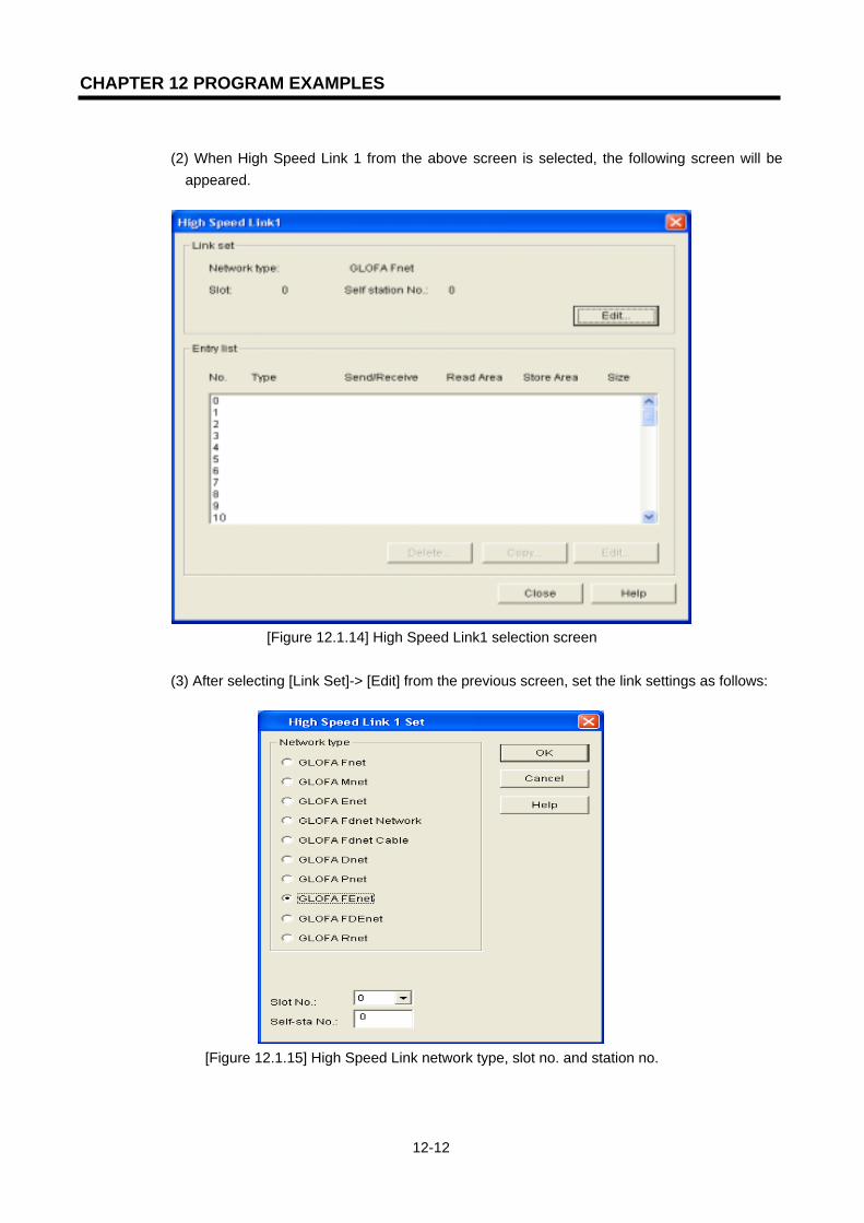
CHAPTER 12 PROGRAM EXAMPLES
12-12
(2) When High Speed Link 1 from the above screen is selected, the following screen will be
appeared.
[Figure 12.1.14] High Speed Link1 selection screen
(3) After selecting [Link Set]-> [Edit] from the previous screen, set the link settings as follows:
[Figure 12.1.15] High Speed Link network type, slot no. and station no.
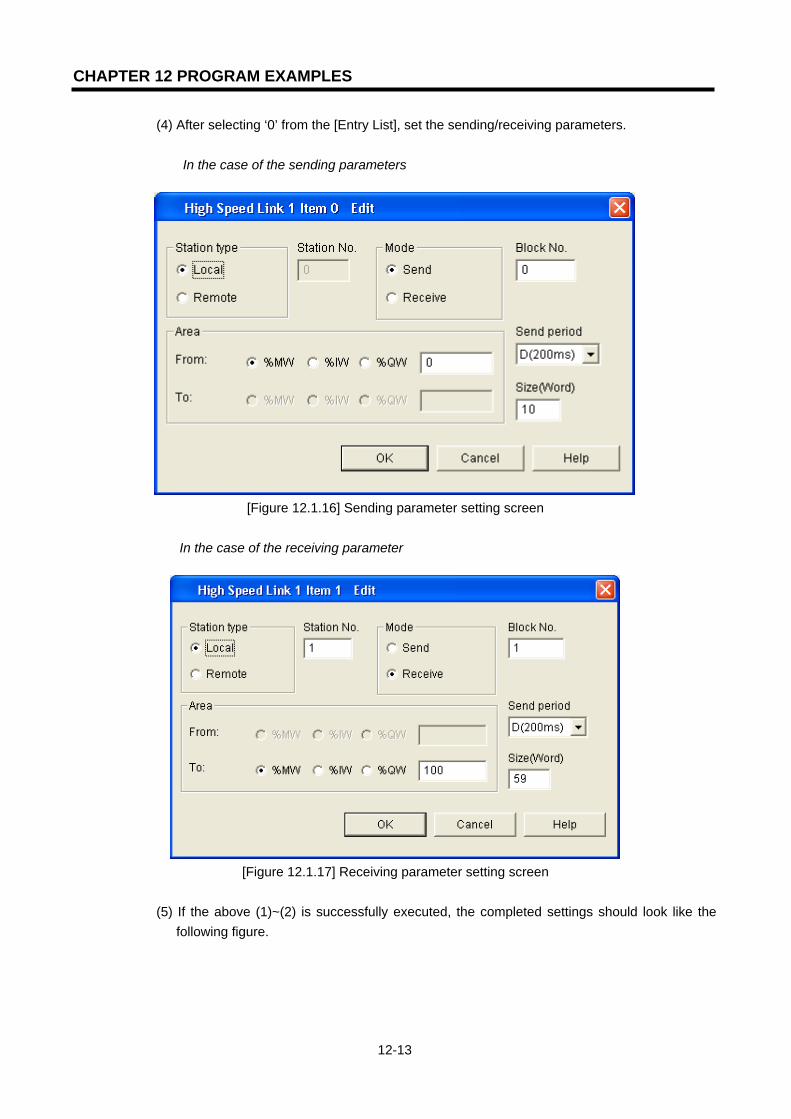
CHAPTER 12 PROGRAM EXAMPLES
12-13
(4) After selecting ‘0’ from the [Entry List], set the sending/receiving parameters.
In the case of the sending parameters
[Figure 12.1.16] Sending parameter setting screen
In the case of the receiving parameter
[Figure 12.1.17] Receiving parameter setting screen
(5) If the above (1)~(2) is successfully executed, the completed settings should look like the
following figure.

CHAPTER 12 PROGRAM EXAMPLES
12-14
[Figure 12.1.18] Completion of the High Speed Link 1 settings
(6) After finishing the High Speed Link parameter settings, select ‘close’. Next, prepare the user program, execute ‘Compile ->Build All’and then write the program to the PLC.
(7) After selecting ‘Online -> Link Enable Setting’, the following window appears:
[Figure 12.1.19] High Speed Link ‘Enable Setting’ and ‘Write’
(8) After changing the PLC mode to RUN, select ‘View / Link Parameter / HS Link 1’ and
check if the communication is performing normally for the setting parameters. (Even the
destination station should be running normally by downloading the relevant program
and the High Speed Link parameters).
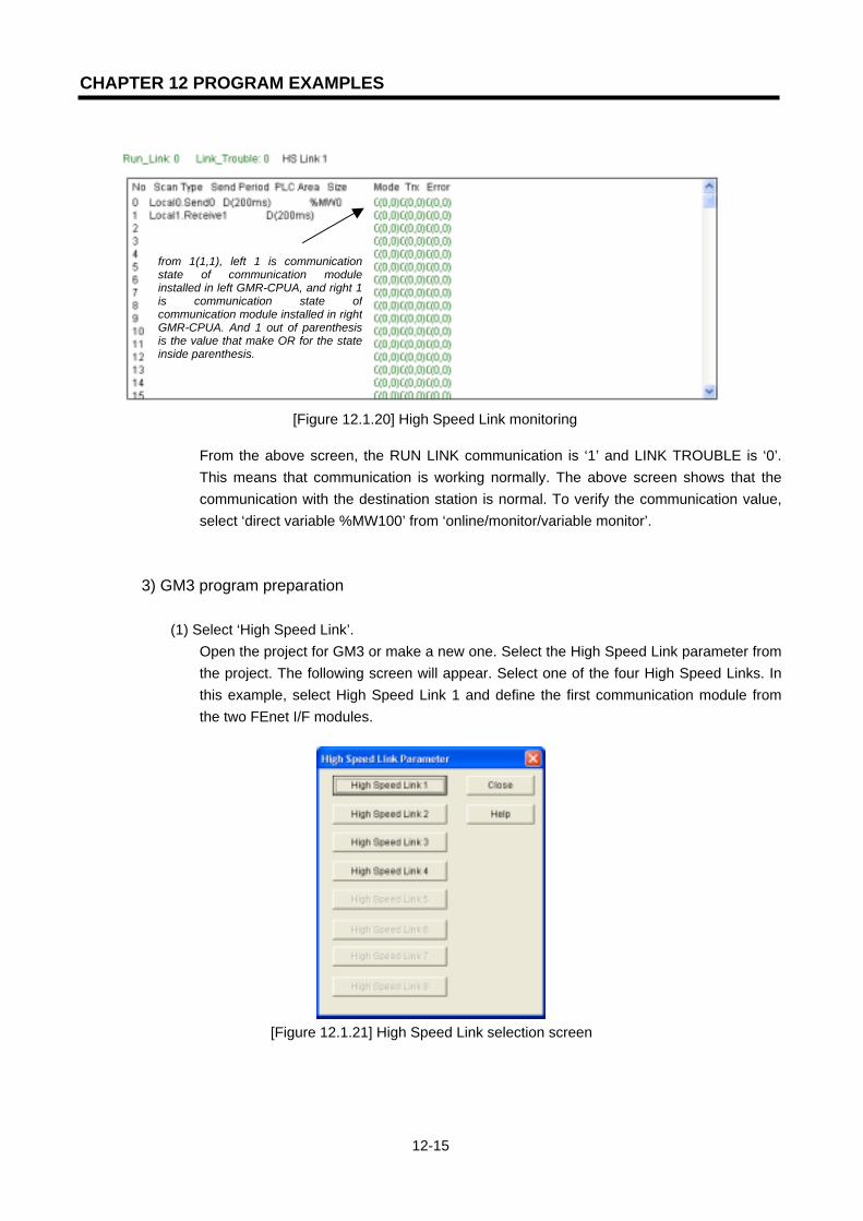
CHAPTER 12 PROGRAM EXAMPLES
12-15
[Figure 12.1.20] High Speed Link monitoring
From the above screen, the RUN LINK communication is ‘1’ and LINK TROUBLE is ‘0’. This means that communication is working normally. The above screen shows that the communication with the destination station is normal. To verify the communication value, select ‘direct variable %MW100’ from ‘online/monitor/variable monitor’.
3) GM3 program preparation
(1) Select ‘High Speed Link’.
Open the project for GM3 or make a new one. Select the High Speed Link parameter from the project. The following screen will appear. Select one of the four High Speed Links. In this example, select High Speed Link 1 and define the first communication module from the two FEnet I/F modules.
[Figure 12.1.21] High Speed Link selection screen
from 1(1,1), left 1 is communicationstate of communication moduleinstalled in left GMR-CPUA, and right 1 is communication state ofcommunication module installed in rightGMR-CPUA. And 1 out of parenthesisis the value that make OR for the stateinside parenthesis.

CHAPTER 12 PROGRAM EXAMPLES
12-16
(2) If High Speed Link 1 from the above screen is selected, the following screen appears.
[Figure 12.1.22] High Speed Link 1 selection screen
(3) After selecting ‘Link Set / Edit’ from the previous screen, carry out the link setting and then
select ‘verify’.
[Figure 12.1.23] High Speed Link network type, the slot number, and station number settings

CHAPTER 12 PROGRAM EXAMPLES
12-17
(4) Select ‘0’ from Entry List and set the sending/receiving parameter.
In the case of the sending parameters
[Figure 12.1.24] Sending parameter setting screen
In the case of the receiving parameters (select ‘1 ‘ from registration list)
[Figure 12.1.25] Receiving parameter setting screen

CHAPTER 12 PROGRAM EXAMPLES
12-18
(5) If the above (1)~(4) is successfully executed, the completed settings should look like the following figure:
[Figure 12.1.26] Completion of the High Speed Link setting
(6) After finishing the High Speed Link parameter of the first FEnet I/F module, select ‘close’.
For the second communication module, set the High Speed Link using the above (1)~(5) procedure. In this case, select High Speed Link 2 and slot no.’1’. Save the saving area of the receiving data in %MW200. Make sure to avoid the overlapping with the area received from the first module. If the settings are completed, it will look like the following figure:
[Figure 12.1.27] High Speed Link network type, slot no. and station no. settings

CHAPTER 12 PROGRAM EXAMPLES
12-19
(7) The following is the method to prepare the user program to add the serial no. to the first word when sending using the High Speed Link parameters. The program will save one data set by comparing the serial no. of the two communication modules when receiving.
The method to add the serial no. when sending
Program preparation when receiving
[Figure 12.1.28] Serial sending program and High Speed Link receiving Function Block
The increase of the serial no. (_T200MS)should match with the sending period ofthe sending parameter. The Variable SERIAL is INT type.
_T200MS: match with the receiving period of the receiving parameter
_HS1MOD[1]/_HS2MOD[1]: receives the data when the destination station mode is ‘1’.
RX_SRI_A/B: the variable indicating the serial no. of the data received from the FEnet I/F module (%MW100). UINT type variable
RCV_A/B: data area received from each FEnet I/F module. UINT Array type variable. Set larger than the receiving data size.
HS_RDATA: area to save the data to receive last among the data received from each FEnet I/F module(%MW1). UINT Arraytype variable. Set more than the receiving data size and set as the same size as RCV_A/B.
Memory address designation area for the variable
RX_SRI_A: %MW100(1word) RCV_A: %MW101 ~ %MW110(10words) RX_SRI_B: %MW200(1word) RCV_B: %MW201 ~ %MW210(10words)
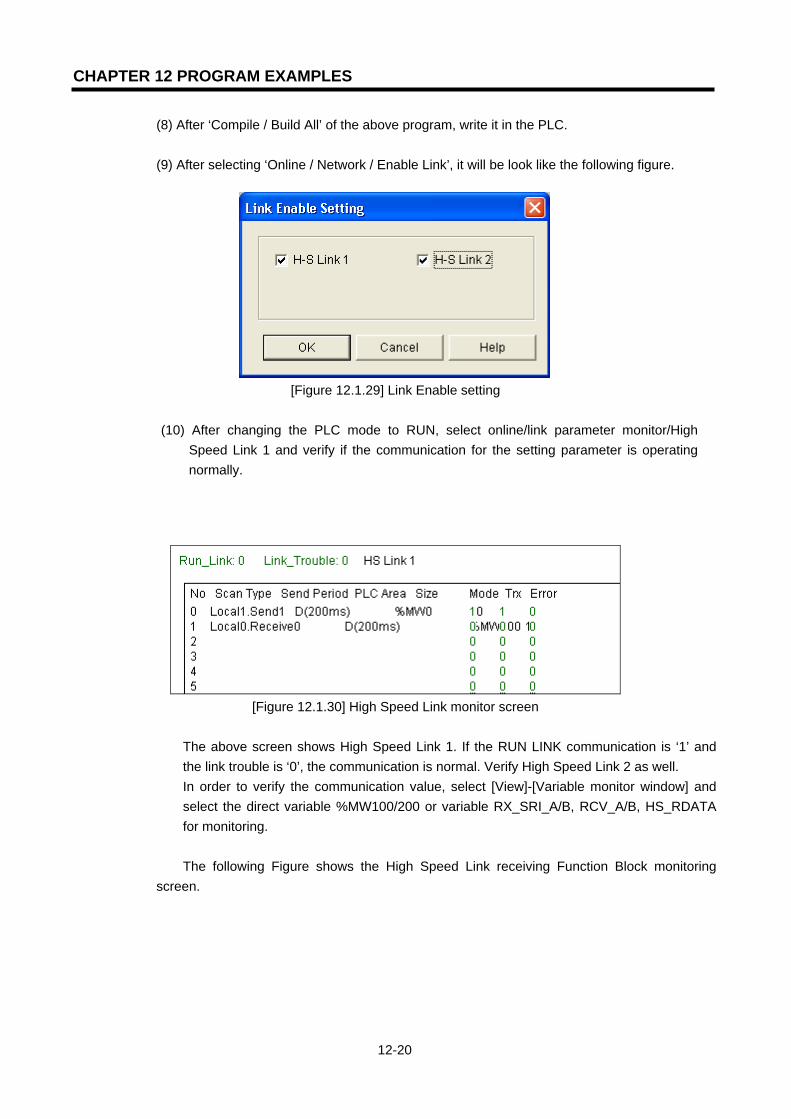
CHAPTER 12 PROGRAM EXAMPLES
12-20
(8) After ‘Compile / Build All’ of the above program, write it in the PLC.
(9) After selecting ‘Online / Network / Enable Link’, it will be look like the following figure.
[Figure 12.1.29] Link Enable setting
(10) After changing the PLC mode to RUN, select online/link parameter monitor/High
Speed Link 1 and verify if the communication for the setting parameter is operating normally.
[Figure 12.1.30] High Speed Link monitor screen
The above screen shows High Speed Link 1. If the RUN LINK communication is ‘1’ and the link trouble is ‘0’, the communication is normal. Verify High Speed Link 2 as well. In order to verify the communication value, select [View]-[Variable monitor window] and select the direct variable %MW100/200 or variable RX_SRI_A/B, RCV_A/B, HS_RDATA for monitoring. The following Figure shows the High Speed Link receiving Function Block monitoring
screen.

CHAPTER 12 PROGRAM EXAMPLES
12-21
Desktop System
[Figure 12.1.31] Monitoring the High Speed Link receiving Function Block
12.1.3 Function Block service between FEnet PLCs
The following system shows an example for Function Block service between GLOFA PLC FEnet
I/F modules.
RS-232C Ethernet network
[Figure 12.1.32] Function Block service system configuration
GLOFA GM3
165.244.149.33
HMI device
GLOFA GM2
165.244.149.56165.244.149.47
G3Q-RY4A
RUNCPU I/F RUNFB-SERVECEHS-SERVICEGMWIN-SERVICEGLOFA-SERVICEFTP-SERVICEH/W-ERROR
10BASE5 ENABLE10BASE2 ENABLE10BASE-T LINK10BASE-T PLRTYTXRX
L00
01
0203
04
05
06
07
COM
L16
17
18
19
04
21
22
23
COM
08L 09
1011
1213
14
15
COM
08L 25
26
27
2829
30
31
COM
+- DC24V
RELAYAC250V 2ADC24V 2A
PROGRAMMABLECONTROLLER
GLO
FA
GM3-PA1A
PWR
G3L-EUEA
RUNCPU I/F RUNFB-SERVECEHS-SERVICEGMWIN-SERVICEGLOFA-SERVICEFTP-SERVICEH/W-ERROR
10BASE5 ENABLE10BASE2 ENABLE10BASE-T LINK10BASE-T PLRTYTXRX
MODE
1
2345
06
7 8 9
0: ON.RUN1: TEST12: TEST2
EXT.POWER
DC IN
+12V
12G
FG
10BASE5
10BASE2
10BASE-T
RUN
GM1-CPUA
RUNSTOP
REMOTEFAIL
ERROR
PAU/REM
STOP
Port no.:3000
TCP ACTIVE Port no.: 3000
TCP PASSIVE
GMWIN
G3Q-RY4A
RUNCPU I/F RUNFB-SERVECEHS-SERVICEGMWIN-SERVICEGLOFA-SERVICEFTP-SERVICEH/W-ERROR
10BASE5 ENABLE10BASE2 ENABLE10BASE-T LINK10BASE-T PLRTYTXRX
L00
01
0203
04
05
06
07
COM
L16
17
18
19
04
21
22
23
COM
08L 09
1011
1213
14
15
COM
08L 25
26
27
2829
30
31
COM
+- DC24V
RELAYAC250V 2ADC24V 2A
PROGRAMMABLECONTROLLER
GLO
FA
GM3-PA1A
PWR
G3L-EUEA
RUNCPU I/F RUNFB-SERVECEHS-SERVICEGMWIN-SERVICEGLOFA-SERVICEFTP-SERVICEH/W-ERROR
10BASE5 ENABLE10BASE2 ENABLE10BASE-T LINK10BASE-T PLRTYTXRX
MODE
1
2345
06
7 8 9
0: ON.RUN1: TEST12: TEST2
EXT.POWER
DC IN
+12V
12G
FG
10BASE5
10BASE2
10BASE-T
RUN
GM1-CPUA
RUNSTOP
REMOTEFAIL
ERROR
PAU/REM
STOP

CHAPTER 12 PROGRAM EXAMPLES
12-22
In the system configuration example, GM2 is connected to GM3 by TCP_ACTIVE mode and
GM3 is connected to GM2 by TCP_PASSIVE. The communication is done as shown in [Table
12.1.3].
Sending/receiving structure Reading
area Saving area
Size (byte)
Channel used
Sending frame:SEND_FRAME S_DATA 100 0 GM2 (165.244.149.56) Receiving frame:RCV_FRAME R_DATA 100 0
Sending frame:SEND_RESP S_DATA 100 0 GM3 (165.244.149.33) Receiving frame:RCV_FRAME R_DATA 100 0
[Table 12.1.3] Defining of the sending/receiving data
1) GM2 PLC settings
First, create or open the project file and determine the PLC type. And then open the program file. After selecting ‘library insert’ for the project, select the library suitable for the CPU type as shown in the following Figure.
[Figure 12.1.33] Select ‘Insert Library’ screen

CHAPTER 12 PROGRAM EXAMPLES
12-23
[Figure 12.1.34] Insert Library
[Figure 12.1.35]~ [Figure 12.1.38] shows the program to send/receive the data by using an Ethernet module installed in the GM2 and GM3 main base and TCP/IP. (For communication using UDP/IP, the method used is the same.)

CHAPTER 12 PROGRAM EXAMPLES
12-24
[Figure 12.1.35] Example of the GM2 program
From the above program example, GM2 and GM3 establish the channel by TCP_ACTIVE. If the channel is established, CH_EN shall be set using the TCP_SEND Function Block, If CH_EN is set, send the data to GM3 by using the 200 ms timer. Sending is accomplished by transmitting 100bytes of S_DATA in the format, defined by Frame Editor. If sending is completed, the TCP_RCV Function Block uses the flag (_ECM1_CH0_FLAG[0]: ON if there is data received by channel no.0 in the FEnet I/F module) to receive the response from the destination station. The received data shall be saved in R_DATA.
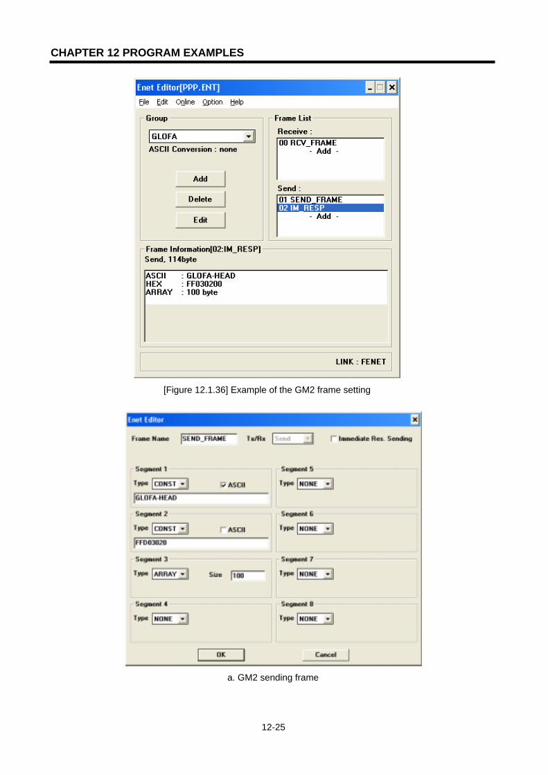
CHAPTER 12 PROGRAM EXAMPLES
12-25
[Figure 12.1.36] Example of the GM2 frame setting
a. GM2 sending frame

CHAPTER 12 PROGRAM EXAMPLES
12-26
b. GM2 receiving frame
[Figure 12.1.37] Frame Editor setting screens
2) Setting GM3 PLC
GM3 establishes the channel by GM2 and TCP_PASSIVE. If the channel is established, CH0EN shall be set and the local station operates as the server. The receiving verification flag under the TCP_RCV Function Block REQ condition (_ECM1_CH0_FLAG[0]: ON if it is receiving data to the receiving frame by channel no.’0’ in the FEnet I/F module in the main base slot no.’0’) in order to verify the data request from the destination station. If data receiving is normal, RCV_NDR shall be set. Make OR for this bit and channel establishment signal CH0_EN bit, and read the MBO data as much as DATA_LEN under TCP_SEND function requirement and send it to GM2.
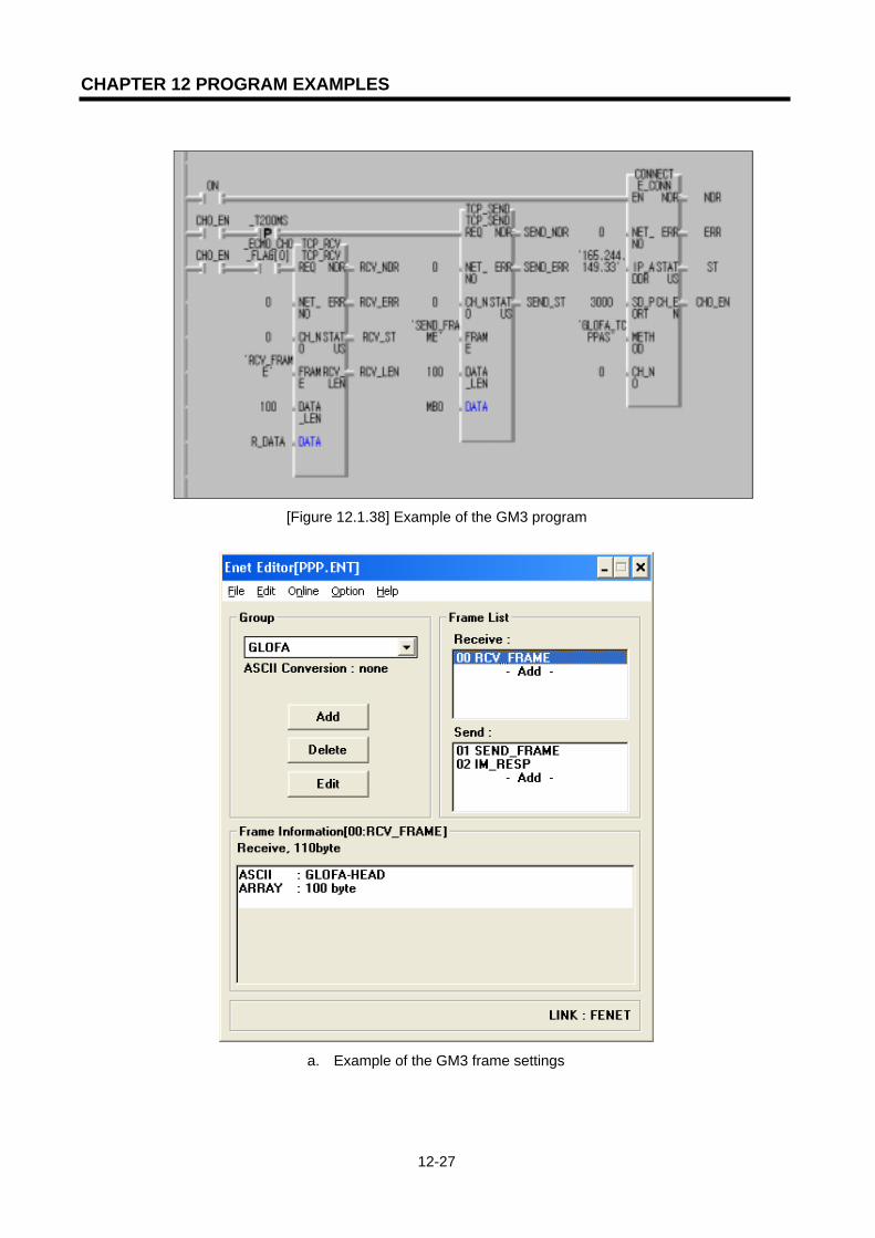
CHAPTER 12 PROGRAM EXAMPLES
12-27
[Figure 12.1.38] Example of the GM3 program
a. Example of the GM3 frame settings

CHAPTER 12 PROGRAM EXAMPLES
12-28
b. GM3 sending frame
c. GM3 receiving frame
[Figure 12.1.39] GM3 PLC frame settings
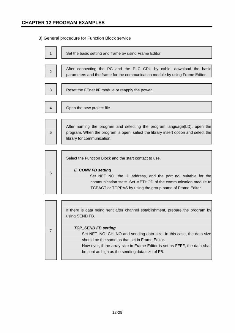
CHAPTER 12 PROGRAM EXAMPLES
12-29
3) General procedure for Function Block service
1 Set the basic setting and frame by using Frame Editor.
2 After connecting the PC and the PLC CPU by cable, download the basic parameters and the frame for the communication module by using Frame Editor.
3 Reset the FEnet I/F module or reapply the power.
4 Open the new project file.
5 After naming the program and selecting the program language(LD), open the program. When the program is open, select the library insert option and select the library for communication.
6
Select the Function Block and the start contact to use. E_CONN FB setting
Set NET_NO, the IP address, and the port no. suitable for the communication state. Set METHOD of the communication module to TCPACT or TCPPAS by using the group name of Frame Editor.
7
If there is data being sent after channel establishment, prepare the program by using SEND FB.
TCP_SEND FB setting Set NET_NO, CH_NO and sending data size. In this case, the data size should be the same as that set in Frame Editor. How ever, if the array size in Frame Editor is set as FFFF, the data shall be sent as high as the sending data size of FB.
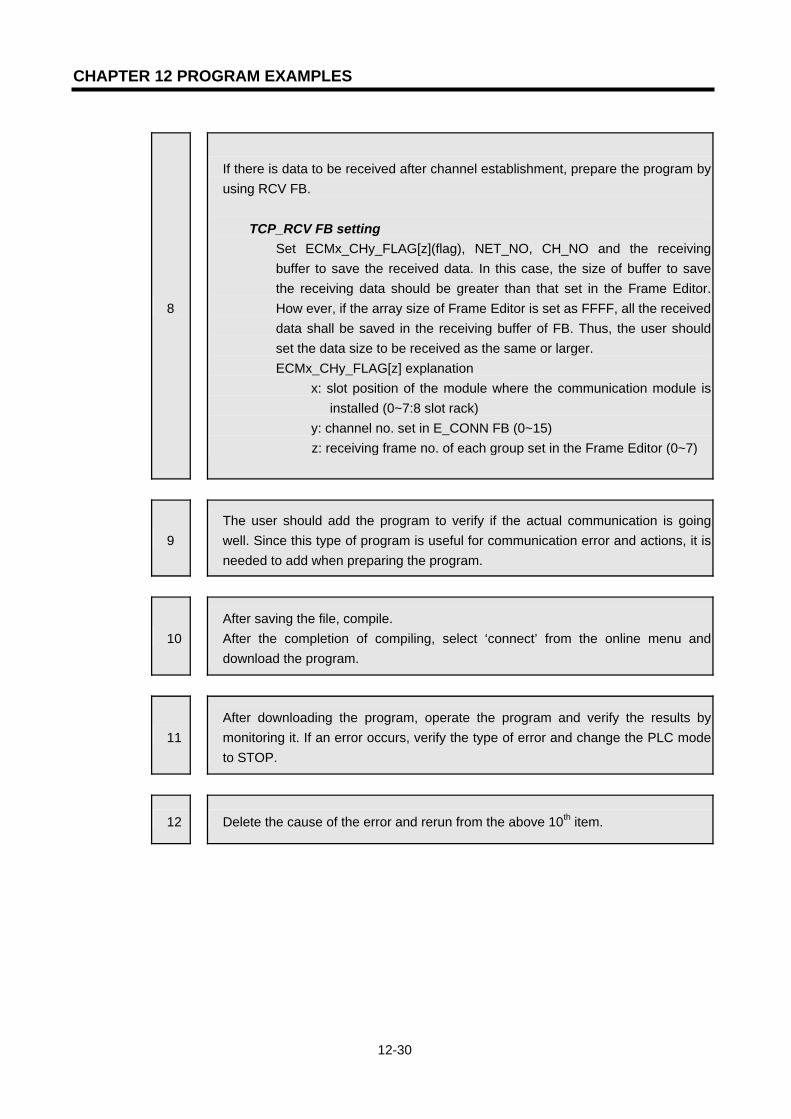
CHAPTER 12 PROGRAM EXAMPLES
12-30
8
If there is data to be received after channel establishment, prepare the program by using RCV FB.
TCP_RCV FB setting Set ECMx_CHy_FLAG[z](flag), NET_NO, CH_NO and the receiving buffer to save the received data. In this case, the size of buffer to save the receiving data should be greater than that set in the Frame Editor. How ever, if the array size of Frame Editor is set as FFFF, all the received data shall be saved in the receiving buffer of FB. Thus, the user should set the data size to be received as the same or larger. ECMx_CHy_FLAG[z] explanation
x: slot position of the module where the communication module is installed (0~7:8 slot rack)
y: channel no. set in E_CONN FB (0~15) z: receiving frame no. of each group set in the Frame Editor (0~7)
9 The user should add the program to verify if the actual communication is going well. Since this type of program is useful for communication error and actions, it is needed to add when preparing the program.
10 After saving the file, compile. After the completion of compiling, select ‘connect’ from the online menu and download the program.
11 After downloading the program, operate the program and verify the results by monitoring it. If an error occurs, verify the type of error and change the PLC mode to STOP.
12 Delete the cause of the error and rerun from the above 10th item.

CHAPTER 12 PROGRAM EXAMPLES
12-31
12.1.4 Function Block service among another manufacturer’s module + PC +
LGIS FEnet I/F module
The system configured like the one below makes the network in two ways. #1 HMI (GLOFA FEnet DRIVER): Client -> GLOFA GM2(dedicated service): server GLOFA GM2(Function Block): Client -> another manufacturer’s PLC: server #2 HMI: Client -> GLOFA GM2(Function Block service): server GLOFA GM2(Function Block): Client -> another manufacturer’s PLC: server
Dedicated service or FB communication FB communication
[Figure 12.1.40] System configuration
The following describes the system for case #1. This is the system configuration that establishes the channel by using another manufacturer’s PLC and TCP ACTIVE based on GM2 between PC(HMI) and another manufacturer’s PLC for communication and uses the dedicated service for PC communication.
Sending/receiving structure Reading
area Saving area
Size
(byte) Use channel
Sending frame:
GLOFA_SEND_FRAMES_DATA (MB100) 100 0
GM2
(165.244.149.47) Receiving frame:
GLOFA_RCV_FRAME(MB3000) R_DATA 100 0
[Table 12.1.4] Defining of the sending/receiving data If the sending data S_DATA area used in the Function Block is set as “%MB100” and the data is transmitted from PC(HMI) to %MB100, the PC data shall be sent to the other manufacturer’s
Another manufacturer’sPLC
165.244.149.31
HMI
GLOFA GM2
165.244.149.56165.244.149.47
Desktop System
G3Q-RY4A
RUNCPU I/F RUNFB-SERVECEHS-SERVICEGMWIN-SERVICEGLOFA-SERVICEFTP-SERVICEH/W-ERROR
10BASE5 ENABLE10BASE2 ENABLE10BASE-T LINK10BASE-T PLRTYTXRX
L00
01
0203
04
05
06
07
COM
L16
17
18
19
04
21
22
23
COM
08L 09
1011
1213
14
15
COM
08L 25
26
27
2829
30
31
COM
+- DC24V
RELAYAC250V 2ADC24V 2A
PROGRAMMABLECONTROLLER
GLO
FA
GM3-PA1A
PWR
G3L-EUEA
RUNCPU I/F RUNFB-SERVECEHS-SERVICEGMWIN-SERVICEGLOFA-SERVICEFTP-SERVICEH/W-ERROR
10BASE5 ENABLE10BASE2 ENABLE10BASE-T LINK10BASE-T PLRTYTXRX
MODE
1
2345
06
7 8 9
0: ON.RUN1: TEST12: TEST2
EXT.POWER
DC IN
+12V
12G
FG
10BASE5
10BASE2
10BASE-T
RUN
GM1-CPUA
RUNSTOP
REMOTEFAIL
ERROR
PAU/REM
STOP
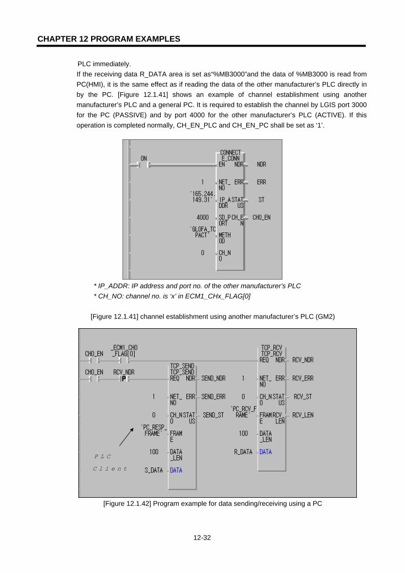
CHAPTER 12 PROGRAM EXAMPLES
12-32
PLC immediately. If the receiving data R_DATA area is set as“%MB3000”and the data of %MB3000 is read from PC(HMI), it is the same effect as if reading the data of the other manufacturer’s PLC directly in by the PC. [Figure 12.1.41] shows an example of channel establishment using another manufacturer’s PLC and a general PC. It is required to establish the channel by LGIS port 3000 for the PC (PASSIVE) and by port 4000 for the other manufacturer’s PLC (ACTIVE). If this operation is completed normally, CH_EN_PLC and CH_EN_PC shall be set as ‘1’.
* IP_ADDR: IP address and port no. of the other manufacturer’s PLC * CH_NO: channel no. is ‘x’ in ECM1_CHx_FLAG[0]
[Figure 12.1.41] channel establishment using another manufacturer’s PLC (GM2)
[Figure 12.1.42] Program example for data sending/receiving using a PC
타사 PLC 에 대해
서 Client 로 동작

CHAPTER 12 PROGRAM EXAMPLES
12-33
[Figure 12.1.42] shows the program example where normal data is received from the PC. The _ECM1_ CH0_FLAG[0] (ON when the FEnet I/F module is installed in the main base slot no. the ’0’ and ‘0’ receiving frame is received normally by channel no.’0’) shall be set and if the PC_RCV_FRAME type data is received from the opposite, 100 data shall be saved in ‘R_DATA’ variable and ‘RCV_NDR’ shall be set. the TCP_SEND Function Block uses the ’RCV_NDR’ bit which is set if the TCP_RCV Function Block is operating normally with a REQ condition. (From the above program, if communication connection is done, communication available every 1 second.) If this bit is set, 100 S_DATA data will be sent to the destination station by ‘PC_RESP_FRAME’ type of TCP_SEND Function Block. (The frame name ‘PC_RCV_FRAM, and ‘PC_RESP_FRAME’ should have been defined in Frame Editor and downloaded in the FEnet I/F module). If the local station is operating as the server for destination station, check if the data requested from the destination station is normally received to the local station and then prepare the program to send the local station data.
[Figure 12.1.43] Program example for sending/receiving using another manufacturer’s PLC [Figure 12.1.43] operates using the same method as [Figure 12.1.42]. It prepares the program by using the local station operate as the client for the destination station. It sends the data to the destination station in advance, and it receives the destination station sends the data normally. [Figure 12.1.41~43] shows the Frame Editor setting example that defined the frame to perform the above program. This shows the example of the frame necessary for communication with another manufacturer’s PLC.

CHAPTER 12 PROGRAM EXAMPLES
12-34
The following describes the system for case #2. This example establishes the channel by using another manufacturer’s PLC and TCP ACTIVE. Based on GM2 between M1, the other manufacturer’s PLC establishes the channel by TCP PASSIVE in order for the computer to send/receive the data [Table 12.1.5] shows the data used to communicate. (For communication with an HMI device, it is possible to use dedicated service or Function Block).
Sending/receiving structure Reading
area Saving area
Size
(byte) Channel used
Sending frame:
PC_RESP_FRAME
GLOFA_SEND_FRAME
S_DATA -- 100 0
GM2
(165.244.149.47) Receiving frame:
PC_RCV_FRAME
GLOFA_RCV_FRAME
-- R_DATA 100 0
[Table 12.1.5] Defining of the sending/receiving data
[Figure 12.1.44] shows the example of channel establishment between another manufacturer’s PLC and a general PC. For the PC, it is required to establish the channel with LGIS port 3000 (PASSIVE). For the other manufacturer’s PLC, the other manufacturer’s port 4000 is required (ACTIVE). If this operation is completed normally, CH_EN_PLC and CH_EN_PC will be set as ‘1’.
* CONNECT (INSTANCE)
1) IP_ADDR(165.244.149.56): operated by the server for High(HMI) 2) SD_PORT(3000): local station port no.
Operated by the Client for the other manufacturer’s PLC Operated by Server for the PC
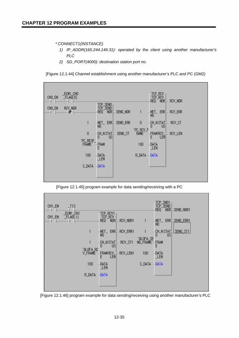
CHAPTER 12 PROGRAM EXAMPLES
12-35
* CONNECT1(INSTANCE)
1) IP_ADDR(165.244.149.31): operated by the client using another manufacturer’s PLC
2) SD_PORT(4000): destination station port no.
[Figure 12.1.44] Channel establishment using another manufacturer’s PLC and PC (GM2)
[Figure 12.1.45] program example for data sending/receiving with a PC
[Figure 12.1.46] program example for data sending/receiving using another manufacturer’s PLC
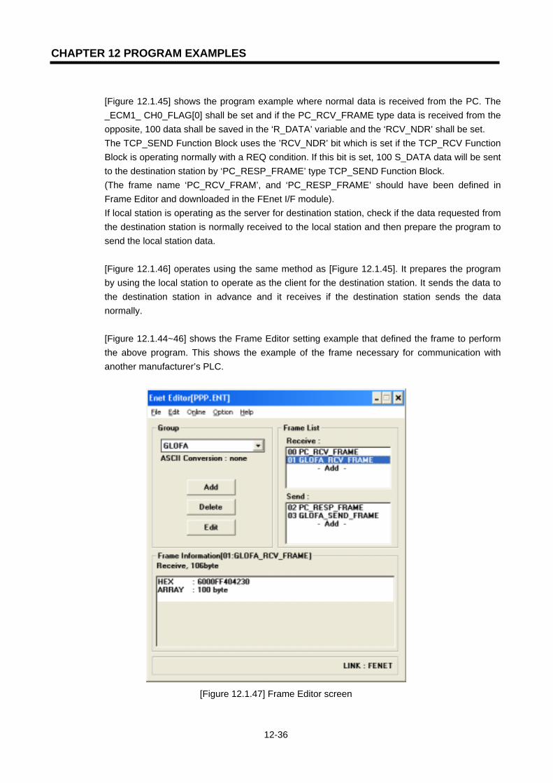
CHAPTER 12 PROGRAM EXAMPLES
12-36
[Figure 12.1.45] shows the program example where normal data is received from the PC. The _ECM1_ CH0_FLAG[0] shall be set and if the PC_RCV_FRAME type data is received from the opposite, 100 data shall be saved in the ‘R_DATA’ variable and the ‘RCV_NDR’ shall be set. The TCP_SEND Function Block uses the ’RCV_NDR’ bit which is set if the TCP_RCV Function Block is operating normally with a REQ condition. If this bit is set, 100 S_DATA data will be sent to the destination station by ‘PC_RESP_FRAME’ type TCP_SEND Function Block. (The frame name ‘PC_RCV_FRAM’, and ‘PC_RESP_FRAME’ should have been defined in Frame Editor and downloaded in the FEnet I/F module). If local station is operating as the server for destination station, check if the data requested from the destination station is normally received to the local station and then prepare the program to send the local station data. [Figure 12.1.46] operates using the same method as [Figure 12.1.45]. It prepares the program by using the local station to operate as the client for the destination station. It sends the data to the destination station in advance and it receives if the destination station sends the data normally. [Figure 12.1.44~46] shows the Frame Editor setting example that defined the frame to perform the above program. This shows the example of the frame necessary for communication with another manufacturer’s PLC.
[Figure 12.1.47] Frame Editor screen

CHAPTER 12 PROGRAM EXAMPLES
12-37
[Figure 12.1.48] Example of a receiving frame registration
[Figure 12.1.49] Example of a receiving frame registration

CHAPTER 12 PROGRAM EXAMPLES
12-38
12.1.5 Redundant CPUs and GM3 Function Block service
This section describes an example of Function Block service between two FEnet I/F modules composed of communication redundancy. The system ([Figure 12.1.50]) configuration shows an example of a network redundancy by using two FEnet I/F modules in a redundancy CPU and GM3 CPU.
[Figure 12.1.50] Example of a redundancy system The program method for a redundancy CPU is the same as the existing method but the single CPU makes the program by using the redundancy Function Block. The table below describes the example to send the data by using TCP/IP and the data contents for communication.
Sending/receiving structure Reading
area
Saving
area
Size
(byte)
Channel
used
Sending frame:SEND_100 S_DATA -- 100 0 Redundancy CPU
(165.244.149.108) Receiving frame:RCV_200 -- R_DATA 200 1
Sending frame:SEND S_DATA -- 200 0 GM3 CPU
(165.244.149.109) Receiving frame:RCV -- R_DATA 100 1
1 SLOT: 165.244.149.1092 SLOT: 165.244.149.109
1 SLOT:165.244.149.1102 SLOT:165.244.149.110
G3L-EUEA
RUNCPU I/F RUNFB-SERVECEHS-SERVICEGMWIN-SERVICEGLOFA-SERVICEFTP-SERVICEH/W-ERROR
10BASE5 ENABLE10BASE2 ENABLE10BASE-T LINK10BASE-T PLRTYTXRXMO
DE12345
06 7890: ON.RUN1: TEST12: TEST2EXT.POWER
DC IN
+12V12GFG
10BASE5
10BASE2
10BASE-T
RUN
GM1-CPUARUNSTOP
REMOTEFAIL
ERROR
PAU/REM ST
OPA
GM1-DIFA
A SELA+B
B AELCPU-ACPU-B
A+B
B
EXTPWR
RS232C
RUN
GM1-CPUARUNSTOP
REMOTEFAIL
ERROR
PAU/REM ST
OP
PROGRAMMABLE
CONTROLLER
GLO
FA
GM3-PA1A
PWR
G3L-EUEA
RUN/BPSTX/BPSRS/BPSACK/DATA-BITNAK/PARITYERR/EVEN-ODDNODEM/STOP-BITSYS-RUN
MODE
RS-232C
12345
06 789
DISPLAY
RS-422
RDARDBSDASDB
SG
FG
RUN/BPSTX/BPSRX/BPSACK/DATA-BITNAK/PARITYERR/EVEN-ODDRS-485/STOP-BITSYS-ERROR
RS-232C
RS-422
G3L-EUEA
RUN/BPSTX/BPSRS/BPSACK/DATA-BITNAK/PARITYERR/EVEN-ODDNODEM/STOP-BITSYS-RUN
MODE
RS-232C
1234
5 06 789
DISPLAY
RS-422RDA
RDBSDA
SDBSG
FG
RUN/BPSTX/BPSRX/BPSACK/DATA-BITNAK/PARITYERR/EVEN-ODDRS-485/STOP-BITSYS-ERROR
RS-232C
RS-422
G3L-EUEA
RUNCPU I/F RUNFB-SERVECEHS-SERVICEGMWIN-SERVICEGLOFA-SERVICEFTP-SERVICEH/W-ERROR
10BASE5 ENABLE10BASE2 ENABLE10BASE-T LINK10BASE-T PLRTYTXRXMO
DE1234
5 067890: ON.RUN1: TEST12: TEST2EXT.POWER
DC IN
+12V12GFG
10BASE5
10BASE2
10BASE-T
PROGRAMMABLE
CONTROLLER
GLO
FA
GM3-PA1A
PWR
G3L-EUEA
RUN/BPSTX/BPSRS/BPSACK/DATA-BITNAK/PARITYERR/EVEN-ODDNODEM/STOP-BITSYS-RUN
MODE
RS-232C
1234
5 06789
DISPLAY
RS-422RDARDBSDASDB
SG
FG
RUN/BPSTX/BPSRX/BPSACK/DATA-BITNAK/PARITYERR/EVEN-ODDRS-485/STOP-BITSYS-ERROR
RS-232C
RS-422
G3L-EUEA
RUN/BPSTX/BPSRS/BPSACK/DATA-BITNAK/PARITYERR/EVEN-ODDNODEM/STOP-BITSYS-RUN
MODE
RS-232C
1234
5 06 789
DISPLAY
RS-422
RDARDBSDASDB
SG
FG
RUN/BPSTX/BPSRX/BPSACK/DATA-BITNAK/PARITYERR/EVEN-ODDRS-485/STOP-BITSYS-ERROR
RS-232C
RS-422
G3Q-RY4ARUNCPU I/F RUNFB-SERVECEHS-SERVICEGMWIN-SERVICEGLOFA-SERVICEFTP-SERVICEH/W-ERROR
10BASE5 ENABLE10BASE2 ENABLE10BASE-T LINK10BASE-T PLRTYTXRX
L00
01
02
03
04
05
06
07
COM
L16
17
18
19
04
21
22
23
COM
08L 09
10
11
1213
14
15
COM
08L 25
26
27
2829
30
31
COM
+- DC24V
RELAYAC250V 2ADC24V 2A
PROGRAMMABLECONTROLLER
GLO
FA
GM3-PA1A
PWR
RUN
GM1-CPUA
RUNSTOP
REMOTEFAIL
ERROR
PAU/REM
STOP
G3L-EUEA
RUNCPU I/F RUNFB-SERVECEHS-SERVICEGMWIN-SERVICEGLOFA-SERVICEFTP-SERVICEH/W-ERROR
10BASE5 ENABLE10BASE2 ENABLE10BASE-T LINK10BASE-T PLRTYTXRX
MODE
1
2345
06
7 8 9
0: ON.RUN1: TEST12: TEST2
EXT.POWER
DC IN
+12V
12G
FG
10BASE5
10BASE2
10BASE-T
G3L-EUEA
RUNCPU I/F RUNFB-SERVECEHS-SERVICEGMWIN-SERVICEGLOFA-SERVICEFTP-SERVICEH/W-ERROR
10BASE5 ENABLE10BASE2 ENABLE10BASE-T LINK10BASE-T PLRTYTXRX
MODE
1
2345
06
7 8 9
0: ON.RUN1: TEST12: TEST2
EXT.POWER
DC IN
+12V
12G
FG
10BASE5
10BASE2
10BASE-T
상위IP1:165.244.149.108IP2:165.244.149.108
G3Q-RY4ARUNCPU I/F RUNFB-SERVECEHS-SERVICEGMWIN-SERVICEGLOFA-SERVICEFTP-SERVICEH/W-ERROR
10BASE5 ENABLE10BASE2 ENABLE10BASE-T LINK10BASE-T PLRTYTXRX
L00
01
02
03
04
05
06
07
COM
L16
17
18
19
04
21
22
23
COM
08L 09
10
11
1213
14
15
COM
08L 25
26
27
2829
30
31
COM
+- DC24V
RELAYAC250V 2ADC24V 2A
PROGRAMMABLECONTROLLER
GLO
FA
GM3-PA1A
PWR
RUN
GM1-CPUA
RUNSTOP
REMOTEFAIL
ERROR
PAU/REM
STOP
G3L-EUEA
RUNCPU I/F RUNFB-SERVECEHS-SERVICEGMWIN-SERVICEGLOFA-SERVICEFTP-SERVICEH/W-ERROR
10BASE5 ENABLE10BASE2 ENABLE10BASE-T LINK10BASE-T PLRTYTXRX
MODE
1
2345
06
7 8 9
0: ON.RUN1: TEST12: TEST2
EXT.POWER
DC IN
+12V
12G
FG
10BASE5
10BASE2
10BASE-T
G3L-EUEA
RUNCPU I/F RUNFB-SERVECEHS-SERVICEGMWIN-SERVICEGLOFA-SERVICEFTP-SERVICEH/W-ERROR
10BASE5 ENABLE10BASE2 ENABLE10BASE-T LINK10BASE-T PLRTYTXRX
MODE
1
2345
06
7 8 9
0: ON.RUN1: TEST12: TEST2
EXT.POWER
DC IN
+12V
12G
FG
10BASE5
10BASE2
10BASE-T
IBM Compatible
IP:165.244.149.110
High Level

CHAPTER 12 PROGRAM EXAMPLES
12-39
Path Connection method Sending frame Receiving frame
Redundancy -> GM3 TCP_ACTIVE(redundancy
based)
SEND_100 -
Redundancy <- GM3 TCP_PASSIVE(redundancy
based)
- RCV_200
GM3 -> redundancy TCP_ACTIVE(GM3 based) SEND -
GM3 -> redundancy TCP_PASSIVE(GM3 based) - RCV
[Table 12.1.6] Defining of the sending/receiving data
1) Preparing the Redundant CPUs (GMR-CPUA) program
(1) Prepare the parameters and frame by using Frame Editor and write it to each FEnet I/F modules. When writing, convert the CPU mode to STOP. After the completion of writing, change the power to ON. (The GMR redundancy CPU has CPU-A, and CPU-B on both sides. If the parameter is downloaded in the master CPU side, the slave CPU will share the contents.)
Basic setting screen (IP address, High Speed Link station no., and media setting)
[Figure 12.1.51] Setting the redundant basic parameters
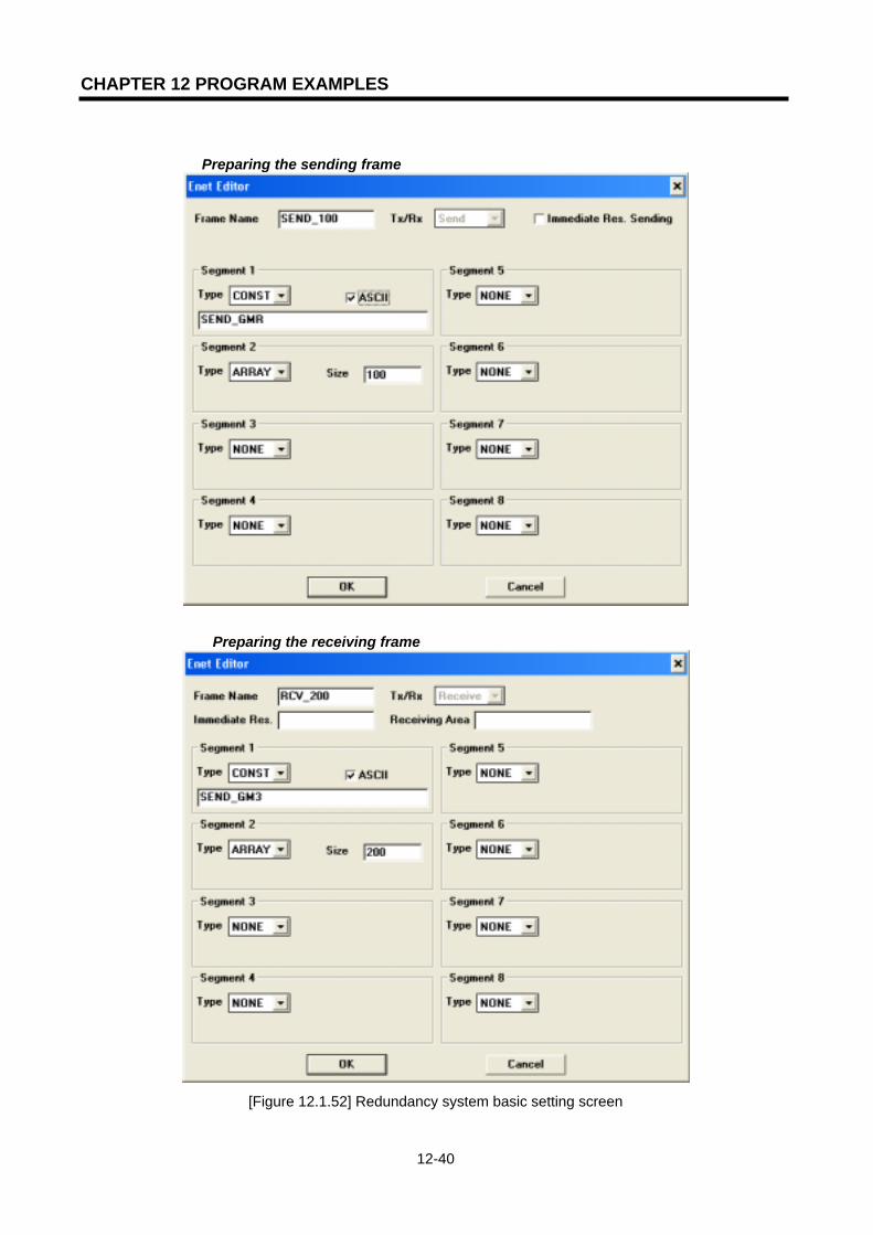
CHAPTER 12 PROGRAM EXAMPLES
12-40
Preparing the sending frame
Preparing the receiving frame
[Figure 12.1.52] Redundancy system basic setting screen
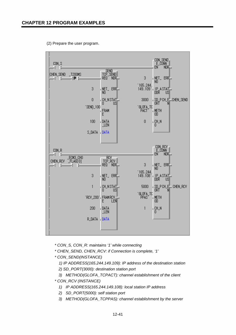
CHAPTER 12 PROGRAM EXAMPLES
12-41
(2) Prepare the user program.
* CON_S, CON_R: maintains ‘1’ while connecting * CHEN_SEND, CHEN_RCV: if Connection is complete, ‘1’ * CON_SEND(INSTANCE)
1) IP ADDRESS(165.244.149.109): IP address of the destination station 2) SD_PORT(3000): destination station port 3) METHOD(GLOFA_TCPACT): channel establishment of the client
* CON_RCV (INSTANCE) 1) IP ADDRESS(165.244.149.108): local station IP address 2) SD_PORT(5000): self station port 3) METHOD(GLOFA_TCPPAS): channel establishment by the server

CHAPTER 12 PROGRAM EXAMPLES
12-42
* S_DATA: saving area of sending data (Current Byte Array type, size:100) * R_DATA: saving area of receiving data (current Byte Array type, size:200)
(Insert library ‘COMMUNI.RFB’ before using)
[Figure 12.1.53] Redundancy system basic setting screen
(3) After compile/make, write using the PLC.
For operation verification, in the case of sending, the redundancy CPU (local station) operates against the destination station (GM3) by TCP ACTIVE, the destination station establishes the connection to the local station and then operates the connection of the local station (CON_S=1). In the case of receiving, it operates the connection from the local station (CON_R=1). That is, in the case of connection, operate the PASSIVE (or SELECT) side first and then operate ACTIVE.
2) Single CPU(GM3-CPUA) program preparation The difference in the program method from the existing method is that the single CPU uses the redundancy Function Block.
(1) Prepare the parameters and frame by using Frame Editor and write to the FEnet I/F module. When writing, convert the CPU mode to STOP. After the completion of writing, turn the power ON. (Prepare the program only for the first FEnet I/F module. The sending/receiving communication by the second module is processed in the Function Block automatically. The two FEnet I/F module should be installed in the base continuously). Basic setting screen (IP address, HS station no., media setting)
[Figure 12.1.54] GM3 basic setting screen

CHAPTER 12 PROGRAM EXAMPLES
12-43
Sending frame preparation
Receiving frame preparation
[Figure 12.1.55] Sending/receiving frame setting screen
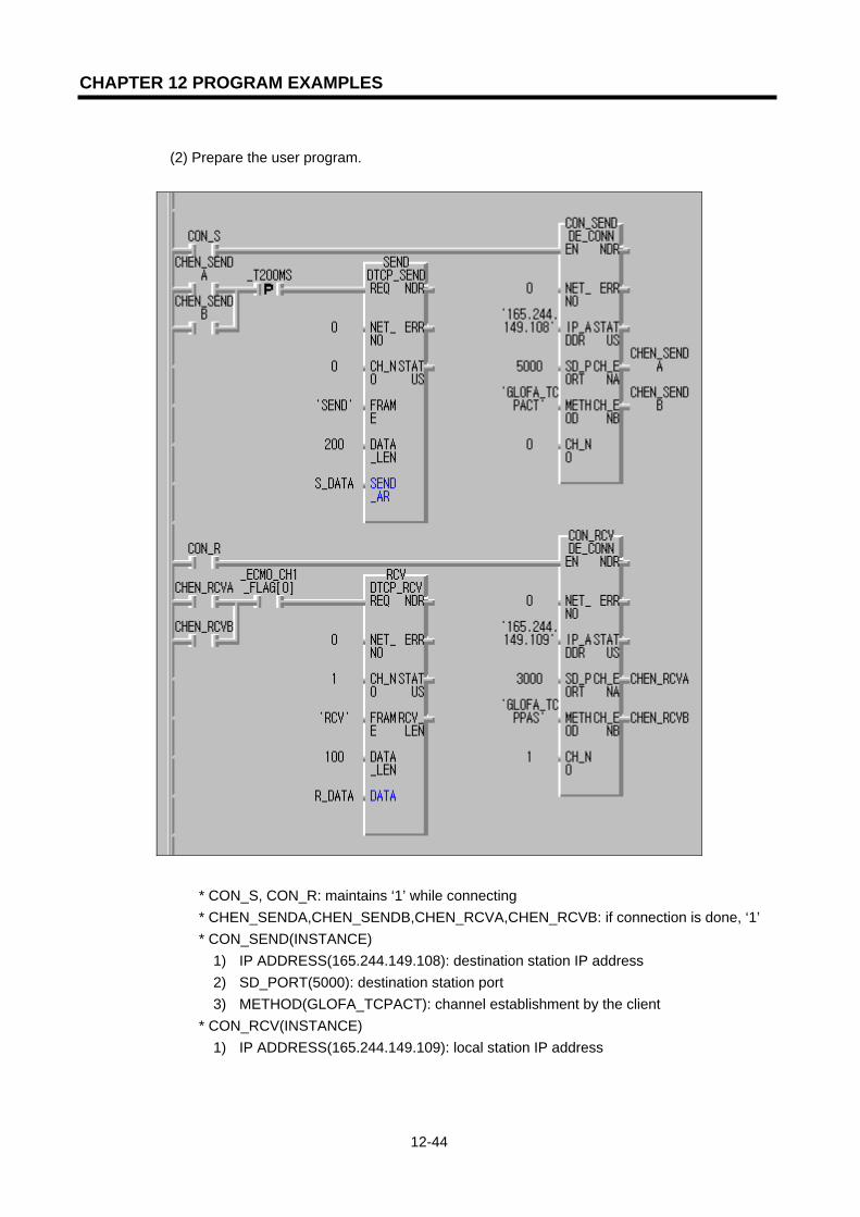
CHAPTER 12 PROGRAM EXAMPLES
12-44
(2) Prepare the user program.
* CON_S, CON_R: maintains ‘1’ while connecting * CHEN_SENDA,CHEN_SENDB,CHEN_RCVA,CHEN_RCVB: if connection is done, ‘1’ * CON_SEND(INSTANCE)
1) IP ADDRESS(165.244.149.108): destination station IP address 2) SD_PORT(5000): destination station port 3) METHOD(GLOFA_TCPACT): channel establishment by the client
* CON_RCV(INSTANCE) 1) IP ADDRESS(165.244.149.109): local station IP address

CHAPTER 12 PROGRAM EXAMPLES
12-45
2) SD_PORT(5000): local station port 3) METHOD(GLOFA_TCPPAS): channel establishment by server
* S_DATA: the saving area of the sending data (current Byte Array type, size:100) * R_DATA: the saving area of the receiving data (current Byte Array type, size:200)
(Insert library ‘DUAL_FB.3FB’ before using)
[Figure 12.1.56] GM3 sending/receiving program The difference between the connection Function Block used in a single module and the redundancy Function Block is that channel enable has outputs from two places instead of one. This allows channel enable to be processed in two FEnet I/F modules. If one or both are enabled, this is used as the REQ condition for the sending/receiving function.
(3) After compile/make, write using the PLC. For operation verification in the case of sending, the GM4C(local station) operates against the destination station (redundancy CPU) by TCP ACTIVE. The destination station establishes the connection to the local station and then operates the connection of the local station (CON_S=1). In the case of receiving, it operates the connection from the local station (CON_R=1) and operates the connection of the destination station. That is, in the case of connection, operate the PASSIVE (or SELECT) side first and then operate ACTIVE.

CHAPTER 12 PROGRAM EXAMPLES
12-46
12.1.6 Redundant CPUs and GM1 Function Block service
This section describes an example of Function Block service between two FEnet I/F modules composed of communication redundancy. The system ([Figure 12.1.57]) configuration shows the example that realizes the network duplication by using two FEnet I/F module between a redundancy CPU and a GM1 CPU.
[Figure 12.1.57] Redundancy system configuration
The program method for a redundancy CPU is the same as the existing method but the single CPU makes the program by using the redundancy Function Block. The table below describes the example to send the data by using TCP/IP and the data contents for communication.
Sending/receiving structure Reading
area Saving area
Size (byte)
Channel used
Sending frame:SEND_100 S_DATA -- 100 0 Redundancy CPU (165.244.149.31
165.244.148.31) Receiving frame:RCV_200 -- R_DATA 200 0
Sending frame: SEND S_DATA -- 200 0 GM1 CPU #1 (165.244.149.32) Receiving frame: RCV -- R_DATA 100 0
Sending frame: SEND S_DATA -- 200 0 GM1 CPU #2 (165.244.148.32) Receiving frame: RCV -- R_DATA 100 0
Ethernet dedicated network 1 or public network 1
Ethernet dedicated network 2 or public network 2
Redundant CPU system(GMR) Single CPU system (GM1 #1)
G3Q-RY4ARUNCPU I/F RUNFB-SERVECEHS-SERVICEGMWIN-SERVICEGLOFA-SERVICEFTP-SERVICEH/W-ERROR
10BASE5 ENABLE10BASE2 ENABLE10BASE-T LINK10BASE-T PLRTYTXRX
L 00
01
0203
04
05
06
07
COM
L 16
17
1819
04
21
22
23
COM
08L09
1011
1213
14
15
COM
08L25
2627
2829
30
31COM
+- DC24V
RELAYAC250V 2ADC24V 2A
PROGRAMMABLECONTROLLER
GLO
FA
GM3-PA1A
PWR
G3L-EUEA
RUNCPU I/F RUNFB-SERVECEHS-SERVICEGMWIN-SERVICEGLOFA-SERVICEFTP-SERVICEH/W-ERROR
10BASE5 ENABLE10BASE2 ENABLE10BASE-T LINK10BASE-T PLRTYTXRX
MODE
1
234
5
06
7 8 9
0: ON.RUN1: TEST12: TEST2
EXT.POWER
DC IN
+12V
12G
FG
10BASE5
10BASE2
10BASE-T
RUN
GM1-CPUA
RUNSTOP
REMOTEFAIL
ERROR
PAU/REM
STOP
G3Q-RY4ARUNCPU I/F RUNFB-SERVECEHS-SERVICEGMWIN-SERVICEGLOFA-SERVICEFTP-SERVICEH/W-ERROR
10BASE5 ENABLE10BASE2 ENABLE10BASE-T LINK10BASE-T PLRTYTXRX
L 00
01
0203
04
05
06
07
COM
L 16
17
1819
04
21
22
23
COM
08L09
1011
1213
14
15
COM
08L25
2627
2829
30
31COM
+- DC24V
RELAYAC250V 2ADC24V 2A
PROGRAMMABLECONTROLLER
GLO
FA
GM3-PA1A
PWR
G3L-EUEA
RUNCPU I/F RUNFB-SERVECEHS-SERVICEGMWIN-SERVICEGLOFA-SERVICEFTP-SERVICEH/W-ERROR
10BASE5 ENABLE10BASE2 ENABLE10BASE-T LINK10BASE-T PLRTYTXRX
MODE
1
234
5
06
7 8 9
0: ON.RUN1: TEST12: TEST2
EXT.POWER
DC IN
+12V
12G
FG
10BASE5
10BASE2
10BASE-T
RUN
GM1-CPUA
RUNSTOP
REMOTEFAIL
ERROR
PAU/REM
STOPPROGRAMMABLECONTROLLER
GLO
FA
GM3-PA1A
PWR
G3L-EUEA
RUNCPU I/F RUNFB-SERVECEHS-SERVICEGMWIN-SERVICEGLOFA-SERVICEFTP-SERVICEH/W-ERROR
10BASE5 ENABLE10BASE2 ENABLE10BASE-T LINK10BASE-T PLRTYTXRX
MODE
1
234
5
06
7 8 9
0: ON.RUN1: TEST12: TEST2
EXT.POWER
DC IN
+12V
12G
FG
10BASE5
10BASE2
10BASE-T
RUN
GM1-CPUA
RUNSTOP
REMOTEFAIL
ERROR
PAU/REM
STOP A
GM1-DIFA
A SELA+B
B AELCPU-ACPU-B
A+B
B
EXTPWR
RS232C
RUN
GM1-CPUA
RUNSTOP
REMOTEFAIL
ERROR
PAU/REM
STOP
G3L-EUEA
RUNCPU I/F RUNFB-SERVECEHS-SERVICEGMWIN-SERVICE
GLOFA-SERVICEFTP-SERVICEH/W-ERROR
10BASE5 ENABLE10BASE2 ENABLE10BASE-T LINK10BASE-T PLRTYTXRX
MODE
1
234
5
06
7 8 9
0: ON.RUN1: TEST1
2: TEST2
EXT.POWER
DC IN
+12V
12G
FG
10BASE5
10BASE2
10BASE-T
PROGRAMMABLECONTROLLER
GLO
FA
GM3-PA1A
PWR
165.244.149.31 165.244.148.31 165.244.149.32 165.244.148.32
Single CPU system(GM1 #2)
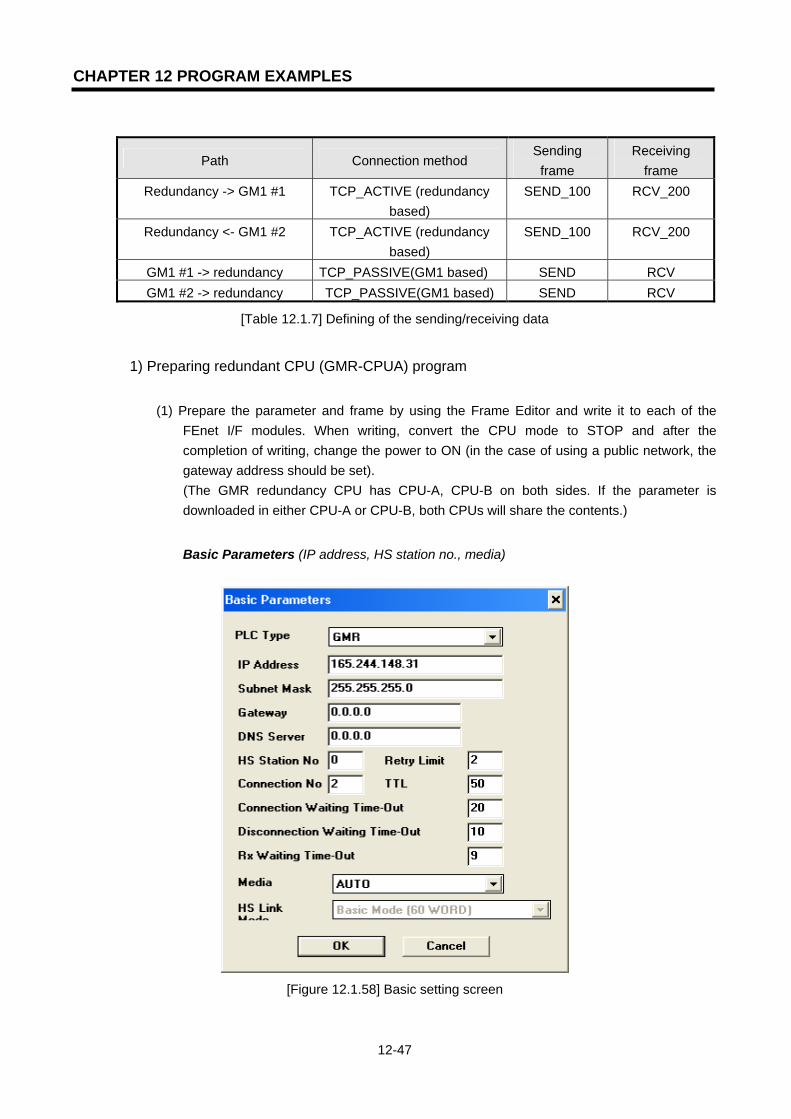
CHAPTER 12 PROGRAM EXAMPLES
12-47
Path Connection method Sending
frame Receiving
frame Redundancy -> GM1 #1 TCP_ACTIVE (redundancy
based) SEND_100 RCV_200
Redundancy <- GM1 #2 TCP_ACTIVE (redundancy based)
SEND_100 RCV_200
GM1 #1 -> redundancy TCP_PASSIVE(GM1 based) SEND RCV GM1 #2 -> redundancy TCP_PASSIVE(GM1 based) SEND RCV
[Table 12.1.7] Defining of the sending/receiving data
1) Preparing redundant CPU (GMR-CPUA) program
(1) Prepare the parameter and frame by using the Frame Editor and write it to each of the FEnet I/F modules. When writing, convert the CPU mode to STOP and after the completion of writing, change the power to ON (in the case of using a public network, the gateway address should be set).
(The GMR redundancy CPU has CPU-A, CPU-B on both sides. If the parameter is downloaded in either CPU-A or CPU-B, both CPUs will share the contents.)
Basic Parameters (IP address, HS station no., media)
[Figure 12.1.58] Basic setting screen

CHAPTER 12 PROGRAM EXAMPLES
12-48
Preparing sending frame
Preparing receiving frame
[Figure 12.1.59] Sending/receiving frame setting screen
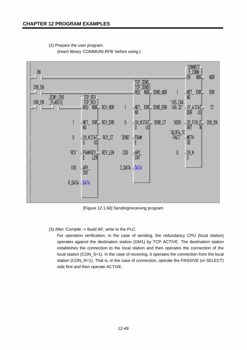
CHAPTER 12 PROGRAM EXAMPLES
12-49
(2) Prepare the user program.
(insert library ‘COMMUNI.RFB’ before using.)
[Figure 12.1.60] Sending/receiving program
(3) After ’Compile -> Build All’, write to the PLC.
For operation verification, in the case of sending, the redundancy CPU (local station) operates against the destination station (GM1) by TCP ACTIVE. The destination station establishes the connection to the local station and then operates the connection of the local station (CON_S=1). In the case of receiving, it operates the connection from the local station (CON_R=1). That is, in the case of connection, operate the PASSIVE (or SELECT) side first and then operate ACTIVE.

CHAPTER 12 PROGRAM EXAMPLES
12-50
2) Preparing single CPU (GM1-CPUA) program
The difference from the existing previous program in the single CPU is the use of the redundancy Function Block.
(1) Prepare the parameter and frame by using the Frame Editor and write to the FEnet I/F
module. When writing, convert the CPU mode to STOP and after the completion of writing, turn the power ON. (Prepare the program only for the first FEnet I/F module. The sending/receiving communication of the second module is processed in the Function Block automatically. The two FEnet I/F module should be installed in the base continuously.)
Basic Parameters (IP address, HS station no., media)
[Figure 12.1.61] Basic setting screen
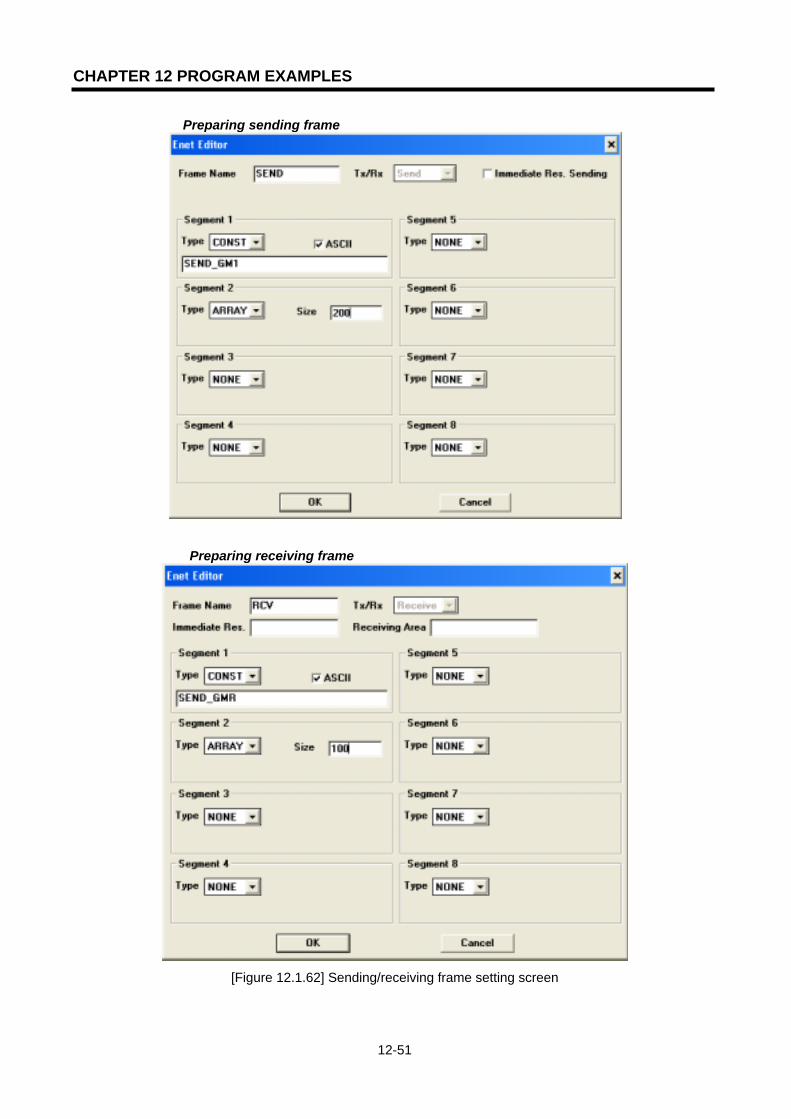
CHAPTER 12 PROGRAM EXAMPLES
12-51
Preparing sending frame
Preparing receiving frame
[Figure 12.1.62] Sending/receiving frame setting screen

CHAPTER 12 PROGRAM EXAMPLES
12-52
(2) Prepare the user program.
(insert library ‘DUAL_FB.1FB’ before using)
[Figure 12.1.63] Sending/receiving program
The difference between the connection Function Block used in a single module and a redundancy Function Block is the output when channel enable has output from two places instead of one. This allows channel enable to be processed in two FEnet I/F modules.If one or both are enabled, this is used as the REQ condition for the sending/receiving function.
(3) After compile/make, write using the PLC. For operation verification, in the case of sending, the GM1(local station) operates against the destination station (redundancy CPU) by TCP ACTIVE. The destination station establishes the connection to the local station and then operates the connection of the local station (CON_S=1). In the case of receiving, it operates the connection from the local station (CON_R=1) and operates the connection of the destination station. That is, in the case of connection, operate PASSIVE (or SELECT) side first and then operate ACTIVE.
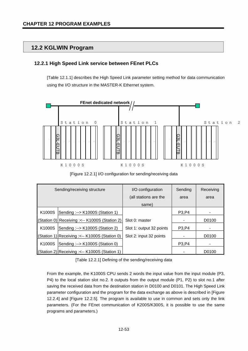
CHAPTER 12 PROGRAM EXAMPLES
12-53
12.2 KGLWIN Program
12.2.1 High Speed Link service between FEnet PLCs
[Table 12.1.1] describes the High Speed Link parameter setting method for data communication
using the I/O structure in the MASTER-K Ethernet system.
[Figure 12.2.1] I/O configuration for sending/receiving data
Sending/receiving structure I/O configuration
(all stations are the
same)
Sending
area
Receiving
area
K1000S Sending :--> K1000S (Station 1) P3,P4 -
(Station 0) Receiving :<-- K1000S (Station 2) Slot 0: master - D0100
K1000S Sending :--> K1000S (Station 2) Slot 1: output 32 points P3,P4 -
(Station 1) Receiving :<-- K1000S (Station 0) Slot 2: input 32 points - D0100
K1000S Sending :--> K1000S (Station 0) P3,P4 -
(Station 2) Receiving :<-- K1000S (Station 1) - D0100
[Table 12.2.1] Defining of the sending/receiving data
From the example, the K1000S CPU sends 2 words the input value from the input module (P3, P4) to the local station slot no.2. It outputs from the output module (P1, P2) to slot no.1 after saving the received data from the destination station in D0100 and D0101. The High Speed Link parameter configuration and the program for the data exchange as above is described in [Figure 12.2.4] and [Figure 12.2.5]. The program is available to use in common and sets only the link parameters. (For the FEnet communication of K200S/K300S, it is possible to use the same programs and parameters.)
FEnet dedicated network
Station 0 Station 2 Station 1
K1000S K1000S K1000S
I/O
POWER
CPU I/OI/OI/OI/OI/O
G3L-E
UTB
I/O
I/O
POWER
CPU I/OI/OI/OI/OI/O
G3L-E
UTB
I/O
I/O
POWER
CPU I/OI/OI/OI/OI/O
G3L-E
UTB
I/O
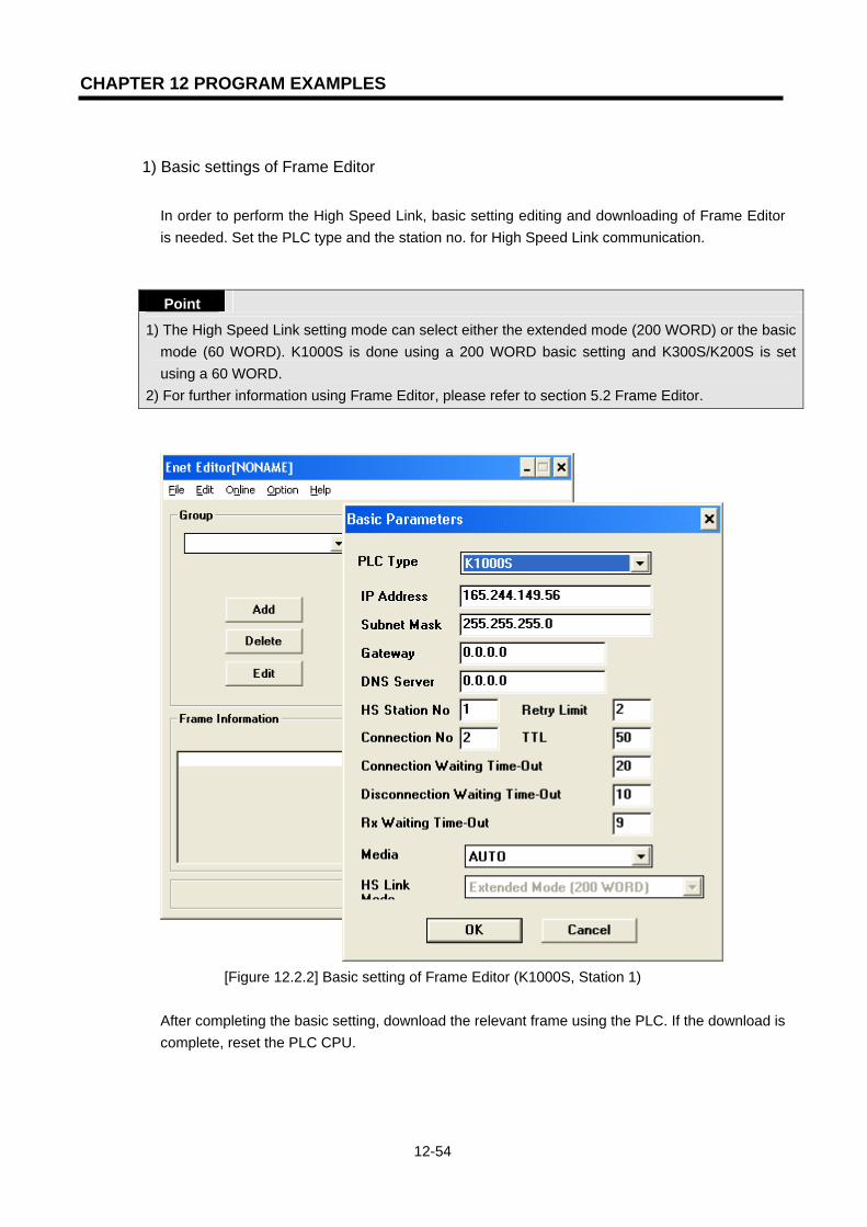
CHAPTER 12 PROGRAM EXAMPLES
12-54
1) Basic settings of Frame Editor
In order to perform the High Speed Link, basic setting editing and downloading of Frame Editor is needed. Set the PLC type and the station no. for High Speed Link communication. Point
1) The High Speed Link setting mode can select either the extended mode (200 WORD) or the basic mode (60 WORD). K1000S is done using a 200 WORD basic setting and K300S/K200S is set using a 60 WORD.
2) For further information using Frame Editor, please refer to section 5.2 Frame Editor.
[Figure 12.2.2] Basic setting of Frame Editor (K1000S, Station 1)
After completing the basic setting, download the relevant frame using the PLC. If the download is complete, reset the PLC CPU.
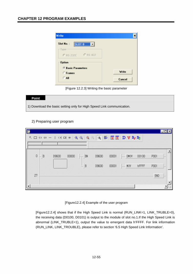
CHAPTER 12 PROGRAM EXAMPLES
12-55
[Figure 12.2.3] Writing the basic parameter
Point
1) Download the basic setting only for High Speed Link communication.
2) Preparing user program
[Figure12.2.4] Example of the user program [Figure12.2.4] shows that if the High Speed Link is normal (RUN_LINK=1, LINK_TRUBLE=0), the receiving data (D0100, D0101) is output to the module of slot no.1.If the High Speed Link is abnormal (LINK_TRUBLE=1), output the value to emergent data h’FFFF. For link information (RUN_LINK, LINK_TROUBLE), please refer to section ‘6.5 High Speed Link Information’.

CHAPTER 12 PROGRAM EXAMPLES
12-56
3) High Speed Link parameter settings
In the system of [Figure 12.2.1], for data exchange of Station 1,2,3 like [Table 12.2.1], the user should prepare the user program like [Figure12.2.4] and then prepare the data sending/receiving map like [Table 12.2.1]. For data sending/receiving like [Table 12.2.1], prepare the High Speed Link parameter and download using the PLC. The procedure to start the High Speed Link is as follows:
(1) Download the station no. and parameters (by Frame Editor). Connect the communication
cable. (2) Prepare the user program (for each station). (3) Prepare the data sending/receiving map. (4) Set the parameters for the GMWIN High Speed Link parameter setting. (5) Execute compile and make from the compile menu. (6) Execute the program and write the parameter from the online menu. (7) Select the Link Enable settings from the online menu and enable High Speed Link suitable
for the setting no. (8) Change the mode to RUN from the online menu. (9) Check the High Speed Link state using the link parameter monitor. (10) If an error occurs, retry from (1).
a. K1000S (Station 0) High Speed Link parameters
b. K1000S (Station 1) High Speed Link parameters
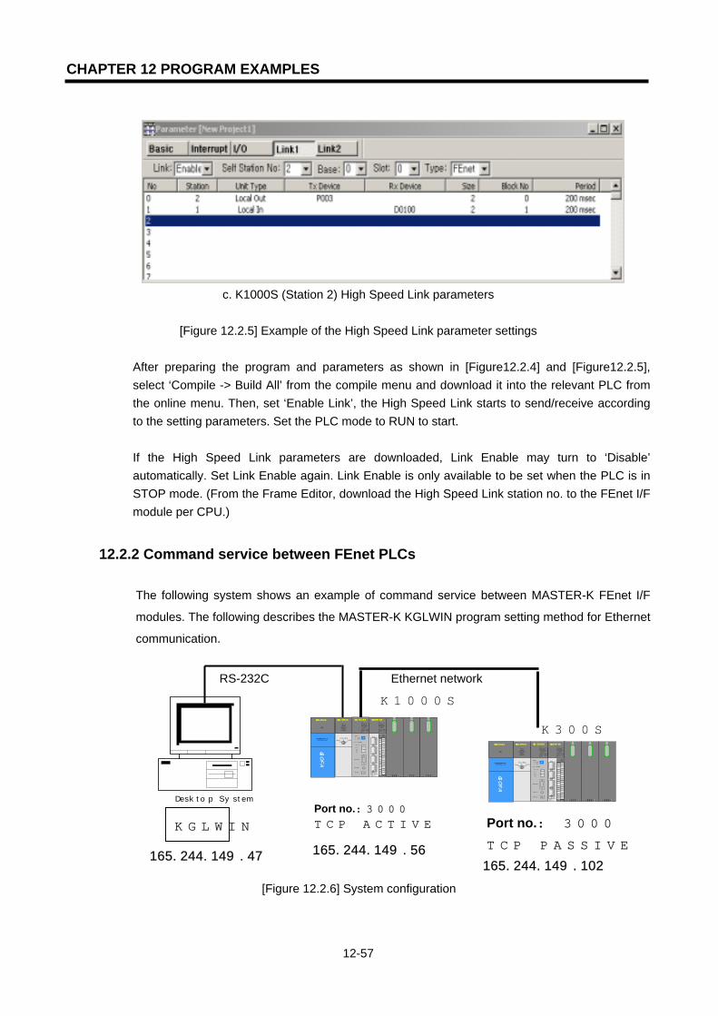
CHAPTER 12 PROGRAM EXAMPLES
12-57
c. K1000S (Station 2) High Speed Link parameters
[Figure 12.2.5] Example of the High Speed Link parameter settings
After preparing the program and parameters as shown in [Figure12.2.4] and [Figure12.2.5], select ‘Compile -> Build All’ from the compile menu and download it into the relevant PLC from the online menu. Then, set ‘Enable Link’, the High Speed Link starts to send/receive according to the setting parameters. Set the PLC mode to RUN to start. If the High Speed Link parameters are downloaded, Link Enable may turn to ‘Disable’ automatically. Set Link Enable again. Link Enable is only available to be set when the PLC is in STOP mode. (From the Frame Editor, download the High Speed Link station no. to the FEnet I/F module per CPU.)
12.2.2 Command service between FEnet PLCs
The following system shows an example of command service between MASTER-K FEnet I/F
modules. The following describes the MASTER-K KGLWIN program setting method for Ethernet
communication.
RS-232C Ethernet network
[Figure 12.2.6] System configuration
K300S
165.244.149.102
K1000S
165.244.149.56165.244.149.47
Desktop System
G3Q-RY4A
RUNCPU I/F RUNFB-SERVECEHS-SERVICEGMWIN-SERVICEGLOFA-SERVICEFTP-SERVICEH/W-ERROR
10BASE5 ENABLE10BASE2 ENABLE10BASE-T LINK10BASE-T PLRTYTXRX
L 00
01
0203
04
05
06
07
COM
L 16
17
18
19
04
21
22
23
COM
08L 09
1011
1213
14
15
COM
08L 25
26
27
2829
30
31COM
+- DC24V
RELAYAC250V 2ADC24V 2A
PROGRAMMABLECONTROLLER
GLO
FA
GM3-PA1A
PWR
G3L-EUEA
RUNCPU I/F RUN
FB-SERVECEHS-SERVICEGMWIN-SERVICEGLOFA-SERVICEFTP-SERVICEH/W-ERROR
10BASE5 ENABLE10BASE2 ENABLE10BASE-T LINK10BASE-T PLRTYTXRX
MODE
1
2345
06
7 8 9
0: ON.RUN1: TEST1
2: TEST2
EXT.POWER
DC IN
+12V
12G
FG
10BASE5
10BASE2
10BASE-T
RUN
GM1-CPUA
RUNSTOP
REMOTEFAIL
ERROR
PAU/REM
STOP
Port no.:3000 TCP ACTIVE Port no.: 3000
TCP PASSIVE
KGLWIN
G3Q-RY4A
RUNCPU I/F RUNFB-SERVECEHS-SERVICEGMWIN-SERVICEGLOFA-SERVICEFTP-SERVICEH/W-ERROR
10BASE5 ENABLE10BASE2 ENABLE10BASE-T LINK10BASE-T PLRTYTXRX
L00
01
0203
04
05
06
07
COM
L16
17
18
19
04
21
22
23
COM
08L 09
1011
1213
14
15
COM
08L 25
26
27
2829
30
31
COM
+- DC24V
RELAYAC250V 2ADC24V 2A
PROGRAMMABLECONTROLLER
GLO
FA
GM3-PA1A
PWR
G3L-EUEA
RUNCPU I/F RUNFB-SERVECEHS-SERVICEGMWIN-SERVICEGLOFA-SERVICEFTP-SERVICEH/W-ERROR
10BASE5 ENABLE10BASE2 ENABLE10BASE-T LINK10BASE-T PLRTYTXRX
MODE
1
2345
06
7 8 9
0: ON.RUN1: TEST12: TEST2
EXT.POWER
DC IN
+12V
12G
FG
10BASE5
10BASE2
10BASE-T
RUN
GM1-CPUA
RUNSTOP
REMOTEFAIL
ERROR
PAU/REM
STOP
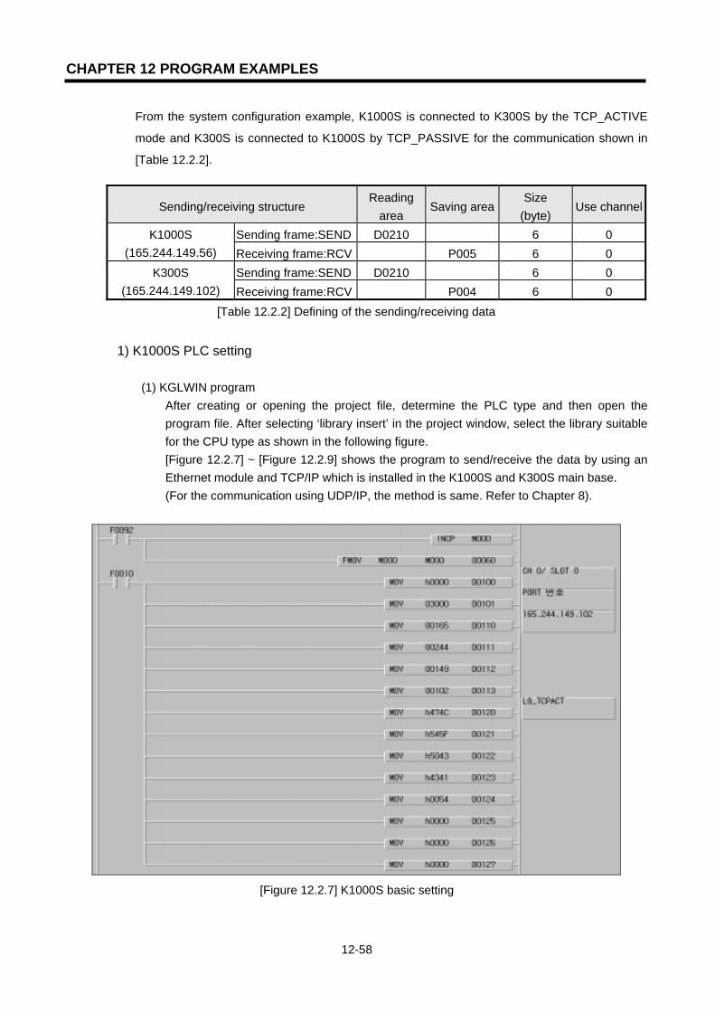
CHAPTER 12 PROGRAM EXAMPLES
12-58
From the system configuration example, K1000S is connected to K300S by the TCP_ACTIVE
mode and K300S is connected to K1000S by TCP_PASSIVE for the communication shown in
[Table 12.2.2].
Sending/receiving structure Reading
area Saving area
Size (byte)
Use channel
Sending frame:SEND D0210 6 0 K1000S (165.244.149.56) Receiving frame:RCV P005 6 0
Sending frame:SEND D0210 6 0 K300S (165.244.149.102) Receiving frame:RCV P004 6 0
[Table 12.2.2] Defining of the sending/receiving data
1) K1000S PLC setting
(1) KGLWIN program After creating or opening the project file, determine the PLC type and then open the program file. After selecting ‘library insert’ in the project window, select the library suitable for the CPU type as shown in the following figure. [Figure 12.2.7] ~ [Figure 12.2.9] shows the program to send/receive the data by using an Ethernet module and TCP/IP which is installed in the K1000S and K300S main base. (For the communication using UDP/IP, the method is same. Refer to Chapter 8).
[Figure 12.2.7] K1000S basic setting

CHAPTER 12 PROGRAM EXAMPLES
12-59
[Figure 12.2.8] ECON channel establishment
[Figure 12.2.9] Sending/receiving program
From the program example, K1000S establishes the channel by K300S and TCP_ACTIVE. If the channel is established, TSND sends the data to K300S by using the timer flag. The data sending is completed by transmitting 6 bytes of D0210 by the frame format defined in the Frame Editor. If the sending is completed, the TRCV command uses the flag to receive the response from the destination station and the receiving data is saved in P005.

CHAPTER 12 PROGRAM EXAMPLES
12-60
(2) Frame Editor setting
[Figure 12.2.10] Example of frame setting in the K1000S
a. Sending frame in K1000S
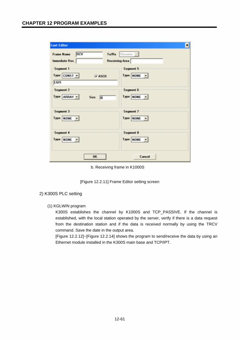
CHAPTER 12 PROGRAM EXAMPLES
12-61
b. Receiving frame in K1000S
[Figure 12.2.11] Frame Editor setting screen
2) K300S PLC setting
(1) KGLWIN program K300S establishes the channel by K1000S and TCP_PASSIVE. If the channel is established, with the local station operated by the server, verify if there is a data request from the destination station and if the data is received normally by using the TRCV command. Save the date in the output area. [Figure 12.2.12]~[Figure 12.2.14] shows the program to send/receive the data by using an Ethernet module installed in the K300S main base and TCP/IPT.

CHAPTER 12 PROGRAM EXAMPLES
12-62
[Figure 12.2.12] K300S basic settings
[Figure 12.2.13] ECON channel establishment

CHAPTER 12 PROGRAM EXAMPLES
12-63
[Figure 12.2.14] Sending/receiving program
(2) Frame Editor setting
[Figure 12.2.15] Example of frame setting in the K300S
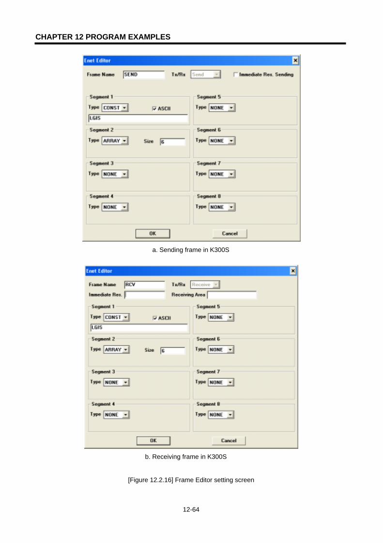
CHAPTER 12 PROGRAM EXAMPLES
12-64
a. Sending frame in K300S
b. Receiving frame in K300S
[Figure 12.2.16] Frame Editor setting screen

CHAPTER 13 TROUBLE SHOOTING
13-1
CHAPTER 13 TROUBLE SHOOTING
This chapter describes the causes and actions for the failures and errors which may occur during system operation. In order to check for the FEnet I/F module error, please follow the procedures below. To check the state of the module, take the necessary actions in the proper order using the trouble shooting guide. Do not repair or disassemble the module on your own.
13.1 Verification through the Communication Module LED This method to verifies the state of the module according to LED ON/OFF.
13.1.1 Error indication It is available to verify the operation status using the LED in the front of the Ethernet module. <G3L-EUxB LED> <G4L-EUxB LED> <G6L-EUxB LED>
[Figure 13.1.1] Structure of the FEnet I/F module LED
LED Error Action
RUN OFF after applying the power to the Ethernet module
1) Poor installation of the Ethernet communication module.
- Check if the DC 5V power supply of the power module is normal/abnormal.
- Check if the communication module is installed in the base correctly.
2) Check if the communication module is in bad condition.
RUN I/F RUN FB/CMD HS PADT PC (MMI) H/W ERR TX RX 10/100
RUN I/F RUN FB/CMD
HS PADT
PC (HMI) TX RX H/W ERR 10/100
RUN PADT (PC)I/F RUN TX FB/CMD RX
HS PHY/ERR

CHAPTER 13 TROUBLE SHOOTING
13-2
LED Error Action
I/F RUN LED is ON or OFF during normal communication
1) Check if the CPU operates normally. 2) Check if the communication module is
installed in the base correctly. 3) Check if the module information is well
recognized through the PADT software.
FB/CMD OFF during function block/ command service
1) Check if the function block/command input is completed correctly.
2) Check if the connection is properly done.
HS OFF during high speed link service
1) Check if the high speed link setting is correct.
2) Check if link enable in the menu is ON.
PADT OFF during remote connection service
1) Check if the IP address for the remote (PADT) connection is correct.
2) Check if the remote connection of the PADT program is released.
PC (HMI) OFF during dedicated service
1) Check if the IP address for dedicated connection is correct.
2) Check if the connection request for HMI (PC) device is completed.
H/W ERR ON during normal communication
1) Check if the media selection using frame editor is done well.
2) Check if there is an interface error with the CPU.
TX ON during data sending 1) Check if the demand frame is receiving
from client normally.
RX ON during data receiving 1) Check if there is an error in the receiving
program. 2) Check if there is an error in frame editing.
10/100 OFF during normal communication
1) Check if the media is composed of 100Mbps. (Auto-Negotiation)

CHAPTER 13 TROUBLE SHOOTING
13-3
13.2 Determining Communication Module Error through GMWIN /
KGLWIN
It is possible to monitor the error state of the communication module using a connection program. It is possible to know from error/warning detail information after the CPU port connection.
[Figure 13.2.1] Monitoring the Error/warning information
If there is a hardware error or a CPU interface error occurs in the module, the LED of the communication module may operate abnormally, but it is still available to verify the state of the module simply by using this dicated program. [Figure 13.2.1] shows the error/warning information through PLC information from GMWIN [online] menu. Please refer to section 13.4 Error code indication.

CHAPTER 13 TROUBLE SHOOTING
13-4
13.3 Determining Module Error by Error Code
Check the error code in [Table 13.3.1] Abnormal operation. [Table 13.2] Troubleshooting describes the details of the error and the necessary actions to take.
13.3.1 Abnormal operation
Error code Error indication Description
E00-01 ECM_12~ECM_15 (See Chapter 7) H/W self-diagnosis error
E00-02 ECM_13, ECM_18 Interfacing error with the CPU
[Table 13.3.1] H/W related error in the communication module
Error code Error indication Description
E01-01 ECM_16 ~ ECM_18 ECM_22 ~ ECM_28
Communication defect (communication not agreeable) Network error
[Table 13.3.2] Abnormal communication status of the communication module
Error code Error indication Description
E02-01 ECM_18 Abnormal interfacing between the Enet module & CPU
[Table 13.3.3] Abnormal interfacing with the communication CPU module
Error code Error indication Description
E03-01 HS link parameter setting error
HS link parameter is set improperly, not set, or if the parameter is crushed after Online Link Enabled Setting
E03-02 HS link not executed The communication is not available as desired even though the HS link parameter is normal after Online Link Enabled Setting
E03-03 Contact of _HSxRLNK/_HSxTRXis not ON when HS link executed
_HSxRLNK is not ON even though the HS linkparameter is normal after Online Link Enabled Setting
E03-04 Contact of _HSxLTBL is ON when HS link executed
HSxLTBL is ON due to an error on the PLC andcommunication after Online Link Enabled Setting and then HS link _HSxRLNK is ON
[Table 13.3.4] Abnormal operation of the HS link function

CHAPTER 13 TROUBLE SHOOTING
13-5
Error code Error indication Description
E04-01 Operation error on E_CONN FB FB’s ERR is ON or FB’s NDR is not 1
E04-01 Operation error on TCP_SEND,UDP_SEND FB
FB’s ERR is ON or FB’s NDR is not 1
E04-01 Operation error on TCP_RCV,UDP_RCV FB FB’s ERR is ON or FB’s NDR is not 1
[Table 1[Table 13.3.5] Abnormal operation of FB
Error Code Error indication Description
E05-01 If [No response] message is displayed when a remote connection is requested
The RS-232C cable is not connected between GMWIN and PLC, or the PLC power is OFF
E05-02 If [Other error message] is displayed when remote connection is requested
Service is not executed normally due to an unsuitable request
[Table 13.3.6] Abnormal operation of PADT communication service function

CHAPTER 13 TROUBLE SHOOTING
13-6
13.3.2 Troubleshooting
1) Error code E00-01: H/W Error
Is the applied Power normal ?
Is the installation environment suitable
for the spec. ?
Yes
N
N
Hardware error
Supplement the installation environment.
Check the power/voltage.
Is the communication module installed
correctly ?
N Yes
Yes
Yes
Yes
N
N
Does the same error occur ?
Rerun the power.
Operation Is it acting normally ?
Perform the troubleshootingfor the relevant error.
Install the communication module correctly.
It’s an error of the communication module or a CPU hardware. Contact the A/S center.

CHAPTER 13 TROUBLE SHOOTING
13-7
2) Error code E00-02: Interface Error
Is the installation environment suitable
for the spec.?
Is the communication module installed in the main
base correctly ?
Is there an error on the connector pin of the
communication module ?
Check the power/voltage.
Change or supplement the condition of the surrounding environment according to the general specifications
Install the communication module in the main base correctly.
Correct the connector pin.
It’s an error of the communication module or a CPU hardware. Contact the A/S center.
Yes
No
Yes
Yes
No
No
No
Interface error
End
Is the applied Power normal ?
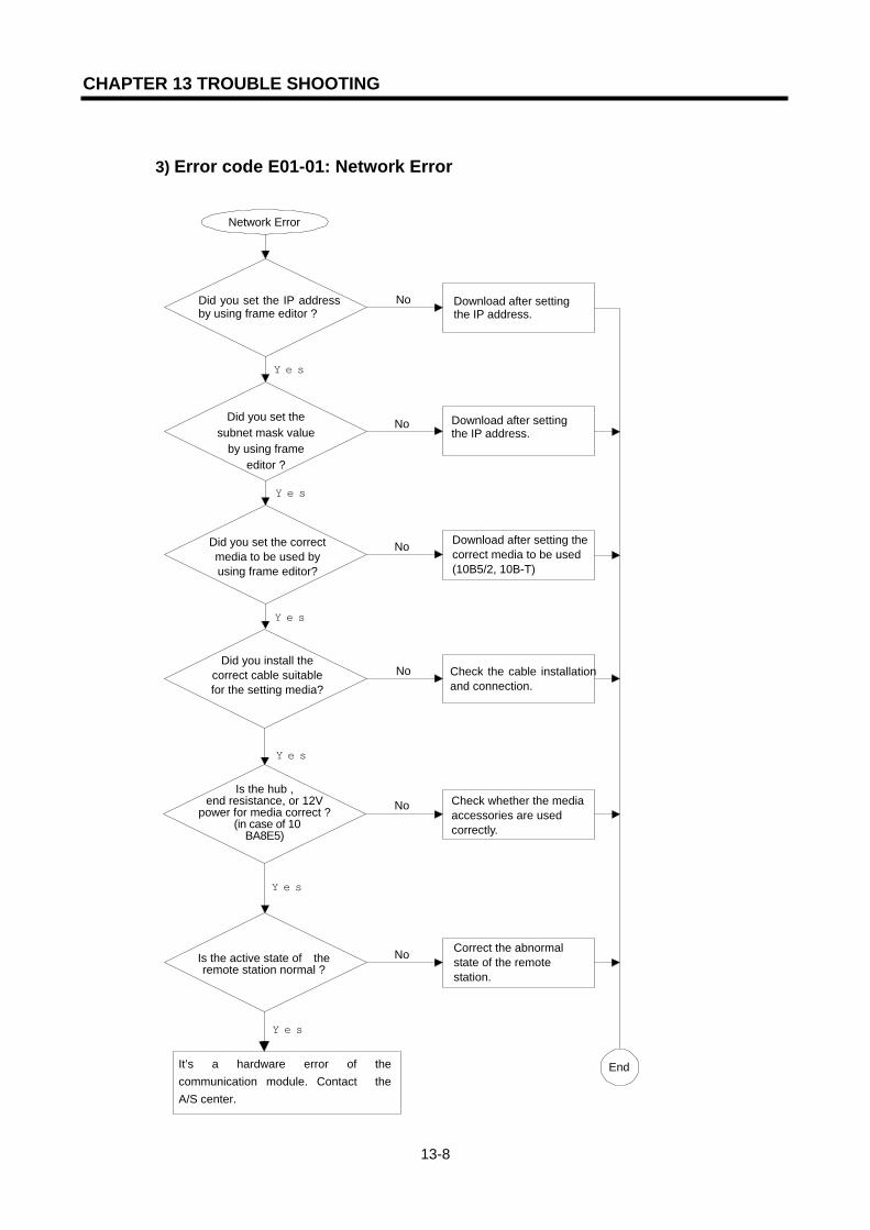
CHAPTER 13 TROUBLE SHOOTING
13-8
3) Error code E01-01: Network Error
NoDid you set the IP addressby using frame editor ?
Did you set the subnet mask value
by using frame editor ?
Did you set the correct media to be used by using frame editor?
Did you install the correct cable suitable for the setting media?
Is the hub , end resistance, or 12V
power for media correct ? (in case of 10
BA8E5)
Download after setting the IP address.
Download after setting the correct media to be used (10B5/2, 10B-T)
Check the cable installationand connection.
Check whether the mediaaccessories are used correctly.
Yes
No
Network Error
End
Is the active state of the remote station normal ?
Correct the abnormal state of the remote station.
Yes
Yes
Yes
Yes
No
No
No
No
It’s a hardware error of the communication module. Contact the A/S center.
Download after setting the IP address.
Yes
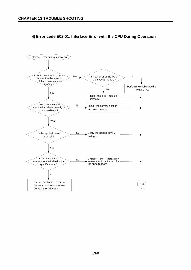
CHAPTER 13 TROUBLE SHOOTING
13-9
4) Error code E02-01: Interface Error with the CPU During Operation
Check the CUP error type. Is it an interface error
of the communication module?
Yes
No
Yes
Yes
Yes
No
No
No
No
Yes
Interface error during operation
End
Is it an error of the I/O or the special module?
It’s a hardware error ofthe communication module.Contact the A/S center.
Is the installation environment suitable for the
specifications ?
Is the communication module installed correctly in
the main base ?
Is the applied power normal ?
Verify the applied power/ voltage.
Install the communication module correctly.
Perform the troubleshooting for the CPU.
Install the error module correctly.
Change the installation environment suitable for the specifications.
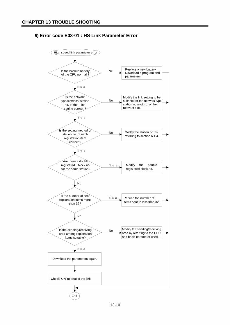
CHAPTER 13 TROUBLE SHOOTING
13-10
5) Error code E03-01 : HS Link Parameter Error
Is the backup battery of the CPU normal ?
Is the network type/slot/local station
no. of the link setting correct ?
Is the setting method of station no. of each registration item
correct ?
Are there a double registered block no. for the same station?
Is the number of sent registration items more
than 32?
No Replace a new battery. Download a program and parameters.
Modify the station no. by referring to section 6.1.4.
Yes
High speed link parameter error
End
NoModify the link setting to be suitable for the network type/station no./slot no. of the relevant slot.
Is the sending/receiving area among registration
items suitable?
Download the parameters again.
No
Yes
Yes
Yes
Modify the sending/receiving area by referring to the CPU and basic parameter used.
No
Reduce the number of items sent to less than 32.
Yes
Modify the double registered block no.
Yes
No
Check ‘ON’ to enable the link
No

CHAPTER 13 TROUBLE SHOOTING
13-11
6) Error code E03-02 : HS Link Operation Error
Did you check ‘ON’ for the Link Enable
setting?
Does the network type/slot no./local
station no. match the relevant slot of the link
settings?
Is the station no. setting method of each
registration item correct ?
Is the sending/ receiving area of the
registration items suitable?
Is there any problem in the network
configuration?
No Check ‘ON’ the relevant Link Enable from the Link Enable Setting.
Modify the station no. setting by referring to section 6.1.4.
Yes
High speed link operation error
End
NoModify the link setting suitable for the network type/station no./slot no. for the relevant slot.
Is there an error in the remote station among the
registration items ?
Download the parameter again.
Yes
Yes
Yes
No
Perform trouble shooting for the remote station.
Yes
Check it accoding to the error code E01-01 flow and modify it.
No
Modify the range of the sending/receiving area referring to the CPU type and section 6.1.4.
No
No
Check ‘ON’ in the Link Enable setting.
Yes

CHAPTER 13 TROUBLE SHOOTING
13-12
7) Error code E03-03: Run Link Error of HS Link
Is the high speed link of each station good ?
Did you check ‘ON’ in Link Enable for each station ?
Is the CPU operation mode of each station in
RUN mode ?
Is the desired station no. setting of each registration
item correct ?
Is there any problem in the network
configuration ?
No Perform trouble shooting for error E03-02 of each station.
Change the mode of each station to RUN mode.
Yes
RUN link of the high speed link is not
End
No Check ‘ON’ in Enable Link for the relevant link of each station.
Is there an error in the remote station among the registration items ?
Download the parameter again.
Yes
Yes
Yes
No
Remove the error of the remote station.
Yes
Check it according to the error code E01-01 flow and modify it.
No
Modify the station no. by referring to section 6.1.4.
No
No
Check ‘ON ‘ in the link enable setting.
Yes

CHAPTER 13 TROUBLE SHOOTING
13-13
8) Error code E03-04 : HS Link Trouble Contact ON
Is there any station with the power OFF?
Is the Link Enable ‘ON’ for each station ?
Is the CPU operation mode of each station in
RUN mode ?
Is there any problem in the network configuration ?
Is there one station where the error occurs?
Yes After taking the necessary actions, turn on the power again.
Change the operation mode of each station to RUN mode.
No
Link trouble contact is ‘ON’.
End
No Check ‘ON’ in Link Enable for the relevant link of each station.
Check the detail information by using the high speed link information monitor.
No
Yes
Yes
Remove the error of the remote station.
Yes
Check it according to the error code E01-01 flow and modify it.
No
No
Download the parameters and check ‘ON’ in the Link Enable setting.
Yes

CHAPTER 13 TROUBLE SHOOTING
13-14
9) Error code E04-01 : E_CONN Function Block Operation Error
E_CONN FB operation error
Is there compile and link error ?
Adjust the port setting since it is overlapped.
Download the frameby frame editor.
Match the group nameof frame editor with FBMETHOD input.
Modify by reference of Appendix ‘A-3 error code’.
Modify by reference ofFB command and language instructions.
Is FB STATUS value
during operation 32?
Is FB STATUS value during operation
86?
Is FB STATUS value
during operation 93?
Modify FB METHOD input.
Is FB STATUS value
during operation 97?
The remote station didnot open the port.
The remote station having the requested IP address does not exist in the
Adjust CH_NO valueless than 15.
End
Convert the CPU mode from STOP to RUN.
Check the network and perform the trouble shooting.
Is there any error in the
network ?
Is FBSTATUS value
during operation 104?
Is FBSTATUS value
during operation 101?
Is FBSTATUS value
during operation 102?
Is FBSTATUS value
during operation 105?
Yes
No Yes
Yes
Yes
Yes
Yes
Yes
No
No
No
No
No
No
No
Yes
No
No
Yes
Yes

CHAPTER 13 TROUBLE SHOOTING
13-15
10) 10 Error code E04-02 : TCP_SEND, UDP_SEND FB Operation Error
TCP_SEND, UDP_SENDfunction block operation error
Is FB STATUS value during operation
84?
Is there a compile and link
error ?
Modify by referring to Appendix ‘A-3 error code’.
Is FB STATUS value during operation
less than 32 ?
Modify by referring to the FB command and language instructions.
Is there any errorin the network ?
Exceeded the max. data number available to send.
FB SD data number is smaller than the arraydata number in thesetting frame. Modify thisnumber.
The setting frame name does not match with the FB frame name. Match it.
Change the CPU mode from STOP to RUN.
End
Perform the trouble shooting related to error code E01-01.
Is FB STATUS value during operation
86?
Is FB STATUS value during operation
108?
Yes
Yes
Yes
Yes
Yes
Yes
No
No
No
No
No
No

CHAPTER 13 TROUBLE SHOOTING
13-16
11) Error code E04-03 : TCP_RCV, UDP_RCV FB Operation Error
TCP_RCV, UDP_RCV function block operation error
Is FB STATUS value during operation
82?
Is there compile and link error ?
Modify by referring to Appendix ‘A-3 error code’.
Is FB STATUS value during operation
less than 32 ?
Modify by referring to the FB command and language instructions.
Perform the trouble shooting related to error code E01-01.
The frame requested from the function block was notreceived.
The received data from the remote station does not match with the frame requested from the function block.
Change the CPU modefrom STOP to RUN.
End
Is FB STATUS value during operation
86?
Is there any error in the network ?
No
Yes
No
Yes
No
Yes
No
Yes
No
Yes

CHAPTER 13 TROUBLE SHOOTING
13-17
12) Error code E05-01 : GMWIN/KGLWIN Communication Time-out
Was the communication port set correctly ?
Is the contents set for the connection mode of ‘project/option’ correct ?
Is the active state of CPU normal ?
Reset the port to be used for GMWIN/KGLWIN communication
Modify the setting contents of the connection mode.
Carry out the trouble shooting for the CPU.
Check the cable cutoff or the connection. Is there an error for RS-232C
cable connection? Yes
Yes
Yes
No
No
No
No
Yes
GMWIN/KGLWIN communication time out
End

CHAPTER 13 TROUBLE SHOOTING
13-18
13) Error code E05-02 : GMWIN/KGLWIN Internal Communication Error
Check the cable cutoff and connection.
Reset the port to be used for GMWIN/KGLWIN communication.
Remove the CPU error by Referring to the CPU user’s manual.
After disconnection, shutdown GMWIN/KGLWIN and connect again.
Is there an error for RS-232C cable connection?
Was the communication port set correctly ?
Is there a serious error in the CPU?
Yes
Yes
Yes
No
No
No
GMWIN/KGLWIN internal communication error
End
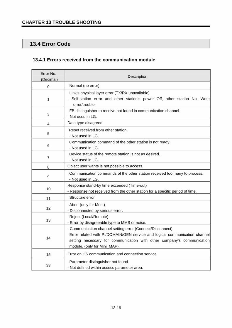
CHAPTER 13 TROUBLE SHOOTING
13-19
13.4 Error Code
13.4.1 Errors received from the communication module
Error No. (Decimal)
Description
0 Normal (no error)
1 Link’s physical layer error (TX/RX unavailable) - Self-station error and other station’s power Off, other station No. Write
error/trouble.
3 FB distinguisher to receive not found in communication channel. - Not used in LG.
4 Data type disagreed
5 Reset received from other station. - Not used in LG.
6 Communication command of the other station is not ready. - Not used in LG.
7 Device status of the remote station is not as desired. - Not used in LG.
8 Object user wants is not possible to access.
9 Communication commands of the other station received too many to process. - Not used in LG.
10 Response stand-by time exceeded (Time-out) - Response not received from the other station for a specific period of time.
11 Structure error
12 Abort (only for Mnet) - Disconnected by serious error.
13 Reject (Local/Remote) - Error by disagreeable type to MMS or noise.
14
- Communication channel setting error (Connect/Disconnect) Error related with PI/DOMAIN/GEN service and logical communication channel
setting necessary for communication with other company’s communication module. (only for Mini_MAP).
15 Error on HS communication and connection service
33 Parameter distinguisher not found. - Not defined within access parameter area.

CHAPTER 13 TROUBLE SHOOTING
13-20
Error No.
(Decimal) Description
34 Wrong address
Error on structure assigned in the spec. of communication module/Out of range.
50 Wrong response - Requested response is not received or error occurred on the other station CPU
113 Object access unsupported - Disobedient to VMD specific and symbolic address, or max.data value
exceeded.
187 Other error code received than assigned. (Other company’s communication
code value) - Other error code received than defined.
13.4.2 STATUS displayed on the CPU
Error No. (Decimal)
Description
16 If position of computer communication module is wrongly assigned.
17 Initializing error of communication module installed on SLOT_NO.
18 Input parameter setting error
19 Parameter length error
20 Wrong response received from the other station
21 Response not received from computer communication module (Stand-by time exceeded – Time out)
80 Disconnection error
82 Not received frame (Defined frame not received)
84 Data count error (Number of data used in FB input discordant with or smaller than that of data defined in the frame)
86 Name doesn’t match (Frame name used in FB input is not on the frame list)
87 Not connected (Channel is not connected)
89 Im TCP Send error (Immediate response error)
90 Im UDP Send error (Immediate response error)
91 Socket error
92 Channel disconnected
93 Basic parameter & frame not set
94 Channel setting error

CHAPTER 13 TROUBLE SHOOTING
13-21
Error No.
(Decimal) Description
96 Channel already set
97 Method input error (Incorrect method used in FB input)
101 Channel No. setting error
102 Setting error of the other stations (Reset)
103 Connection stand-by
104 The IP set for the opposite station is not on the network.
105 The PASSIVE port of the other station is not open.
106 Channel disconnected by stand-by time.
107
Setting number of FB channels exceeded (Number of E_CONN for use exceeded) Setting number of FB channels = 16 - Exclusive connections (Basic parameters of frame editor)
108 Max. TX number exceeded (Since ASCII data = HEX data * 2, the number of ASCII data shall not exceed 1,400 byte)
117 Wrong head of frame header in exclusive service (‘LGIS-GLOFA’)
118 Wrong length of frame header in exclusive service
119 Wrong checksum of frame header in exclusive service
120 Wrong command in exclusive service
121 Domain/PI service requested by unauthorized station in exclusive service (Error occurs if Domain/PI service is requested by the other station when Domain/PI is unavailable in UDP but already used through TCP)
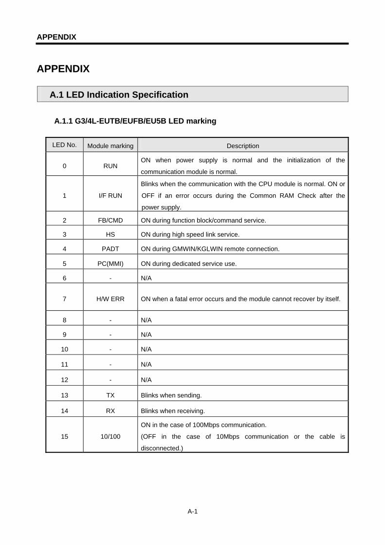
APPENDIX
A-1
APPENDIX
A.1 LED Indication Specification
A.1.1 G3/4L-EUTB/EUFB/EU5B LED marking
LED No. Module marking Description
0 RUN ON when power supply is normal and the initialization of the
communication module is normal.
1 I/F RUN
Blinks when the communication with the CPU module is normal. ON or
OFF if an error occurs during the Common RAM Check after the
power supply.
2 FB/CMD ON during function block/command service.
3 HS ON during high speed link service.
4 PADT ON during GMWIN/KGLWIN remote connection.
5 PC(MMI) ON during dedicated service use.
6 - N/A
7 H/W ERR ON when a fatal error occurs and the module cannot recover by itself.
8 - N/A
9 - N/A
10 - N/A
11 - N/A
12 - N/A
13 TX Blinks when sending.
14 RX Blinks when receiving.
15 10/100
ON in the case of 100Mbps communication.
(OFF in the case of 10Mbps communication or the cable is
disconnected.)
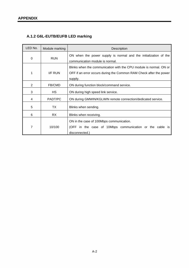
APPENDIX
A-2
A.1.2 G6L-EUTB/EUFB LED marking
LED No. Module marking Description
0 RUN ON when the power supply is normal and the initialization of the
communication module is normal.
1 I/F RUN
Blinks when the communication with the CPU module is normal. ON or
OFF if an error occurs during the Common RAM Check after the power
supply.
2 FB/CMD ON during function block/command service.
3 HS ON during high speed link service.
4 PADT/PC ON during GMWIN/KGLWIN remote connection/dedicated service.
5 TX Blinks when sending.
6 RX Blinks when receiving.
7 10/100
ON in the case of 100Mbps communication.
(OFF in the case of 10Mbps communication or the cable is
disconnected.)

APPENDIX
A-3
A.2 Flag List
A.2.1 Special relay
1) F area relay list
Contact Function Description
F0000 RUN mode ON when the CPU is in RUN mode
F0001 Program mode ON when the CPU is in Program mode
F0002 Pause mode ON when the CPU is in Pause mode
F0003 Debug mode ON when the CPU is in Debug mode
F0006 Remote mode ON when the CPU is in Remote mode
F0007 User memory install ON when User memory is installed
F0008 ~ F0009 No use
F000A User memory operation ON when the User memory is operating
F000B ~ F000E No use
F000F STOP command ON when performing the STOP command
F0010 Always ON Always ON
F0011 Always OFF Always OFF
F0012 1 scan ON 1 scan ON
F0013 1 scan OFF 1 scan OFF
F0014 Reverse at every scan Reverse at every scan
F0015 ~ F001F No use
F0020 1 step RUN ON when 1 step RUN operates during debug mode
F0021 Break Point RUN ON when Break Point RUN operates during debug mode
F0022 Scan RUN ON when scan RUN operates during debug mode
F0023 Contact value match
RUN
ON when contact value match RUN operates during
debug mode
F0024 Word value match RUN ON when word value match RUN operates during debug
mode
F0025 ~ F002F No use
F0030 Heavy failure ON when a heavy failure error occurs
F0031 Light failure ON when a light failure error occurs
F0032 WDT error ON when a Watch Dog time error occurs
F0033 I/O combination error ON when an I/O error occurs (in the case when more than
one bit among F0040 ~ F005F is ON)
F0034 Battery voltage error ON when battery voltage is less than the standard value
F0035 Fuse error ON in the case when the output module Fuse is cutoff
F0036 ~ F0038 No use

APPENDIX
A-4
Contact Function Description
F0039 Backup normal ON if data backup is normal.
F003A Time data error ON when there is a time data Setting error
F003B Program replacing ON when program editing occurs during RUN
F003C Error during program replacement ON when an error occurs in program editing during RUN
F003D ~ F003F No use
F0040 ~ F005F I/O error ON for the relevant bit when the reserved I/O (parameter setting) is different from the actual I/O module or the I/O is added/removed.
F0060 ~ F006F Error code save Save the system error code (refer to 2.9)
F0070 ~ F008F Fuse cutoff state save ON for the relevant slot bit in case of an output module Fuse cutoff
F0090 20ms period Clock
F0091 100ms period Clock
F0092 200ms period Clock
F0093 1s period Clock
F0094 2s period Clock
F0095 10s period Clock
F0096 20s period Clock
F0097 60s period Clock
ON/OFF repeat at regular intervals
F0098 ~ F009F No use
F0100 User Clock 0 F0101 User Clock 1 F0102 User Clock 2
F0103 User Clock 3
F0104 User Clock 4
F0105 User Clock 5
F0106 User Clock 6
F0107 User Clock 7
ON/OFF repeat as much as designated by Duty command
F0108 ~ F101F No use
F0110 Operation error flag ON if an operation error occurs
F0111 Zero flag ON if an operation result is ”0”
F0112 Carry flag ON if an operation result is ‘carry’
F0113 Output Off ON when performing an OUTPUT command
F0114 Common RAM R/W error ON when a special module common memory Access Error occurs
F0115 Operation error flag (latch) ON when an operation error occurs (latch)
F0116 ~ F011F No use
On Off
On Off
N1 scan On
N2 scan Off
DUTY F010x N1 N2
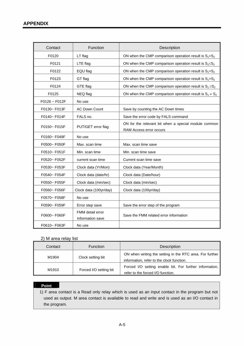
APPENDIX
A-5
Contact Function Description
F0120 LT flag ON when the CMP comparison operation result is S1<S2
F0121 LTE flag ON when the CMP comparison operation result is S1≤S2
F0122 EQU flag ON when the CMP comparison operation result is S1=S2
F0123 GT flag ON when the CMP comparison operation result is S1>S2
F0124 GTE flag ON when the CMP comparison operation result is S1 ≥S2
F0125 NEQ flag ON when the CMP comparison operation result is S1 ≠ S2
F0126 ~ F012F No use
F0130~ F013F AC Down Count Save by counting the AC Down times
F0140~ F014F FALS no. Save the error code by FALS command
F0150~ F015F PUT/GET error flag ON for the relevant bit when a special module common
RAM Access error occurs
F0160~ F049F No use
F0500~ F050F Max. scan time Max. scan time save
F0510~ F051F Min. scan time Min. scan time save
F0520~ F052F current scan time Current scan time save
F0530~ F053F Clock data (Yr/Mon) Clock data (Year/Month)
F0540~ F054F Clock data (date/hr) Clock data (Date/hour)
F0550~ F055F Clock data (min/sec) Clock data (min/sec)
F0560~ F056F Clock data (100yr/day) Clock data (100yr/day)
F0570~ F058F No use
F0590~ F059F Error step save Save the error step of the program
F0600~ F060F FMM detail error
Information save Save the FMM related error information
F0610~ F063F No use
2) M area relay list
Contact Function Description
M1904 Clock setting bit ON when writing the setting in the RTC area. For further
information, refer to the clock function.
M1910 Forced I/O setting bit Forced I/O setting enable bit. For further information,
refer to the forced I/O function.
Point
1) F area contact is a Read only relay which is used as an input contact in the program but not used as output. M area contact is available to read and write and is used as an I/O contact in the program.

APPENDIX
A-6
A.2.2 Special data register (High Speed Link)
1) Detail of the High speed link flags x : K1000S=9, K300S/K200S=4 m : high speed link type no.
Bit position Key word Contents Description
Dx600.0 _HSmRLINK RUN_LINK information of high speed link
This indicates that all station is acting normally by the parameter set in high speed link and is ON under the following condition. 1. When all station set in the parameter is RUN
mode and no error 2. When all data block set in the parameter
communicates normally 3. When parameter set in each station set in the
parameter communicates normally, Once RUN_LINK is ‘ON’, it maintains ‘ON’ unless it stops by LINK DISABLE.
Dx600.1 _HSmLTRBL
Abnormal information of high speed link (LINK_TROUBLE)
In the state that _HSmRLINK is ‘ON’, when the communication state of the station and data block set in the parameter is as follows, this flag is ‘ON’. 1. When the station set in the parameter is not
‘RUN’ mode, 2. When there is an error in the station set in the
parameter, . When the communication state of data block set in
the parameter is not smooth, LINK TROUBLE is ‘ON’ when the above 1,2,3 condition occurs, and OFF if the condition returns to the normal state.
Dx601.0 ~ Dx604.15
_HSmSTATE[k] (k=0~63)
General communication state information of k data block set in high speed link parameter
Indicates the general state of communication information for each data block of the setting parameter _HSmSTATE[k] = _HSmMOD[k] & _HSmTRX[k] & _HSmERR[k]
Dx605.0 ~ Dx608.15
_HSmMOD[k] (k=0~63)
Mode information(RUN = 1, Others = 0)
Indicates operation mode of the station set in k data block of parameter
Dx609.0 ~ Dx612.15
_HSmTRX[k] (k=0~63)
State info. (Normal=1, Abnormal=0)
Indicates if the communication state of k data block of parameter is smooth as set in.
Dx613.0 ~ Dx616.15
_HSmERR[k] (k=0~63)
State info. 0000000 (Error=1, normal=0)
Indicates if there is an error in the communication state of k data block of parameter.

APPENDIX
A-7
Point 1) k is a block no. and indicates the information of the 64 blocks (0~63) by 4 Words (16 blocks per
1 Word). For example, mode information (_HS0MOD) indicates the information of block 0~15 for Dx605, block 16~31for Dx606, block 32~47 for Dx607, block 48~63 for Dx608. Thus, the mode information for block no.55 is indicated in Dx608.7.
2) High speed link detail flag when m=1~3 High speed link type D area address Remarks
High Speed Link2 (m=1) Dx620 ~ Dx633
High Speed Link3 (m=2) Dx640 ~ Dx653
High Speed Link4 (m=3) Dx660 ~ Dx673
When m=1~3 comparing ‘m=0’by simple calculation formula, the D area address is as follows : * Formula: D area address when m=1~3 = address
of Table 3 + 20 × m
3) Data link relay (L area list) x : slot no, n : channel(0~15)
Key word Address Description
L0000 ~ L0007 Frame no. received by channel 0 of slot no. 0 *
L0000 ~ L000F Frame no. received by channel 1 of slot no. 0
L0010 ~ L0017 Frame no. received by channel 2 of slot no. 0
... …
L0070 ~ L0077 Frame no. received by channel 14 of slot no. 0
_RCV0_ECM[n]
L0070 ~ L007F Frame no. received by channel 15 of slot no. 0
_RCV1_ECM[n] L0080~L05F Frame no. received by channel 0~15 of slot no. 1
.
.
.
.
.
.
.
.
.
_RCV7_ECM[n] L0560~L63F Frame no. received by channel 0~15 of slot no. 7 * Slot no.0 is the communication module which is mounted on the no.0 place on the base. (not the slot
no.)
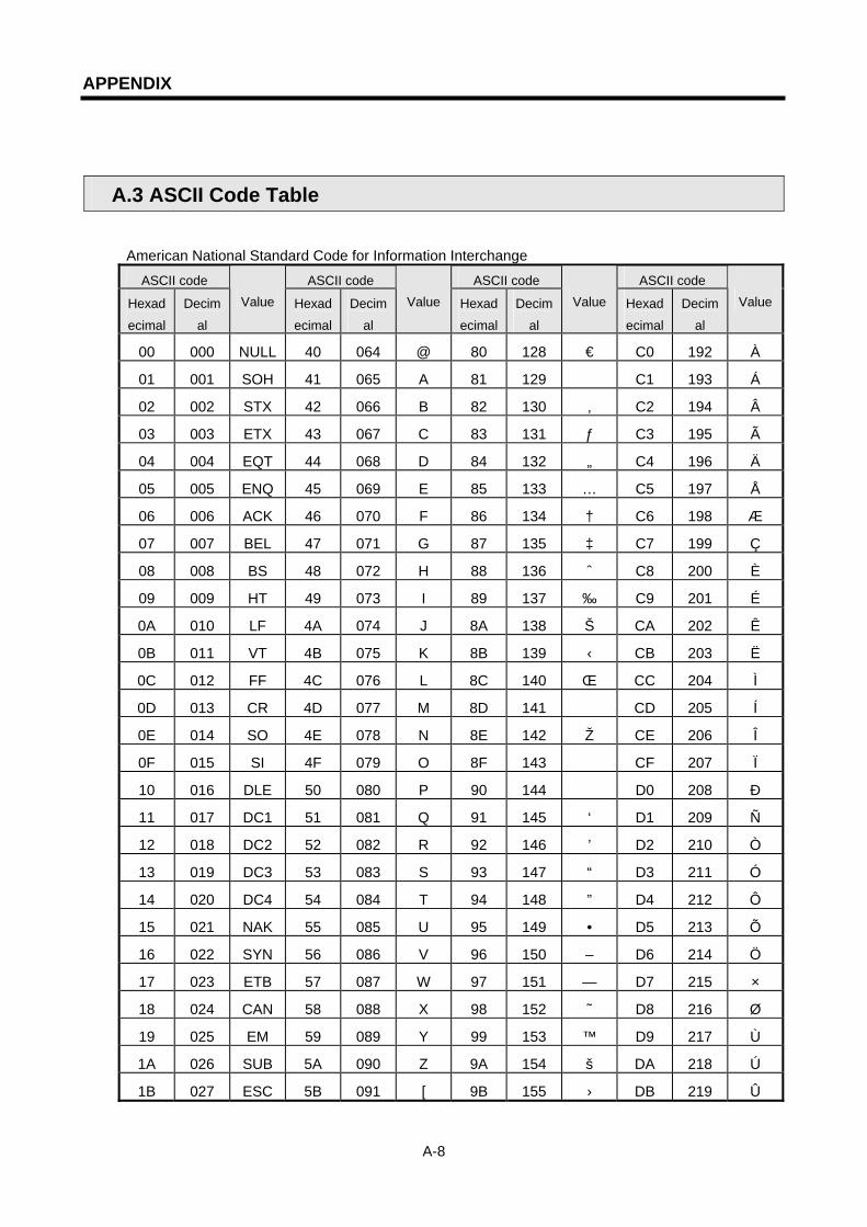
APPENDIX
A-8
A.3 ASCII Code Table
American National Standard Code for Information Interchange
ASCII code ASCII code ASCII code ASCII code
Hexad
ecimal
Decim
al
Value Hexad
ecimal
Decim
al
Value Hexad
ecimal
Decim
al
Value Hexad
ecimal
Decim
al
Value
00 000 NULL 40 064 @ 80 128 € C0 192 À 01 001 SOH 41 065 A 81 129 C1 193 Á 02 002 STX 42 066 B 82 130 ‚ C2 194 Â 03 003 ETX 43 067 C 83 131 ƒ C3 195 Ã 04 004 EQT 44 068 D 84 132 „ C4 196 Ä 05 005 ENQ 45 069 E 85 133 … C5 197 Å 06 006 ACK 46 070 F 86 134 † C6 198 Æ
07 007 BEL 47 071 G 87 135 ‡ C7 199 Ç 08 008 BS 48 072 H 88 136 ˆ C8 200 È 09 009 HT 49 073 I 89 137 ‰ C9 201 É 0A 010 LF 4A 074 J 8A 138 Š CA 202 Ê 0B 011 VT 4B 075 K 8B 139 ‹ CB 203 Ë 0C 012 FF 4C 076 L 8C 140 Œ CC 204 Ì 0D 013 CR 4D 077 M 8D 141 CD 205 Í 0E 014 SO 4E 078 N 8E 142 Ž CE 206 Î 0F 015 SI 4F 079 O 8F 143 CF 207 Ï 10 016 DLE 50 080 P 90 144 D0 208 Ð 11 017 DC1 51 081 Q 91 145 ‘ D1 209 Ñ 12 018 DC2 52 082 R 92 146 ’ D2 210 Ò 13 019 DC3 53 083 S 93 147 “ D3 211 Ó 14 020 DC4 54 084 T 94 148 ” D4 212 Ô 15 021 NAK 55 085 U 95 149 • D5 213 Õ 16 022 SYN 56 086 V 96 150 – D6 214 Ö 17 023 ETB 57 087 W 97 151 — D7 215 × 18 024 CAN 58 088 X 98 152 ˜ D8 216 Ø 19 025 EM 59 089 Y 99 153 ™ D9 217 Ù 1A 026 SUB 5A 090 Z 9A 154 š DA 218 Ú 1B 027 ESC 5B 091 [ 9B 155 › DB 219 Û
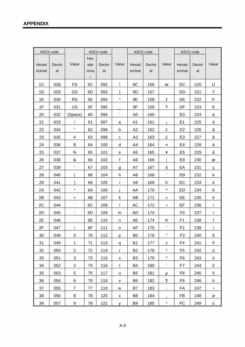
APPENDIX
A-9
ASCII code ASCII code ASCII code ASCII code
Hexad
ecimal
Decim
al
Value Hex
ade
cima
l
Decim
al
Value Hexad
ecimal
Decim
al
Value Hexad
ecimal
Decim
al
Value
1C 028 FS 5C 092 \ 9C 156 œ DC 220 Ü 1D 029 GS 5D 093 ] 9D 157 DD 221 Ý 1E 030 RS 5E 094 ^ 9E 158 ž DE 222 Þ 1F 031 US 5F 095 _ 9F 159 Ÿ DF 223 ß 20 032 (Space) 60 096 ` A0 160 E0 224 à 21 033 ! 61 097 a A1 161 ¡ E1 225 á 22 034 " 62 098 b A2 162 ¢ E2 226 â 23 035 # 63 099 c A3 163 £ E3 227 ã 24 036 $ 64 100 d A4 164 ¤ E4 228 ä 25 037 % 65 101 e A5 165 ¥ E5 229 å 26 038 & 66 102 f A6 166 ¦ E9 230 æ
27 039 ' 67 103 g A7 167 § EA 231 ç 28 040 ( 68 104 h A8 168 ¨ EB 232 è 29 041 ) 69 105 i A9 169 © EC 233 é 2A 042 * 6A 106 j AA 170 ª ED 234 ê 2B 043 + 6B 107 k AB 171 « EE 235 ë 2C 044 ` 6C 108 l AC 172 ¬ EF 236 ì 2D 045 - 6D 109 m AD 173 F0 237 í 2E 046 . 6E 110 n AE 174 ® F1 238 î 2F 047 / 6F 111 o AF 175 ¯ F2 239 ï 30 048 0 70 112 p B0 176 ° F3 240 ð 31 049 1 71 113 q B1 177 ± F4 241 ñ 32 050 2 72 114 r B2 178 ² F5 242 ò 33 051 3 73 115 s B3 179 ³ F6 243 ó 34 052 4 74 116 t B4 180 ´ F7 244 ô 35 053 5 75 117 u B5 181 µ F8 245 õ 36 054 6 76 118 v B6 182 ¶ F9 246 ö 37 055 7 77 119 w B7 183 · FA 247 ÷ 38 056 8 78 120 x B8 184 ¸ FB 248 ø 39 057 9 79 121 y B9 185 ¹ FC 249 ù
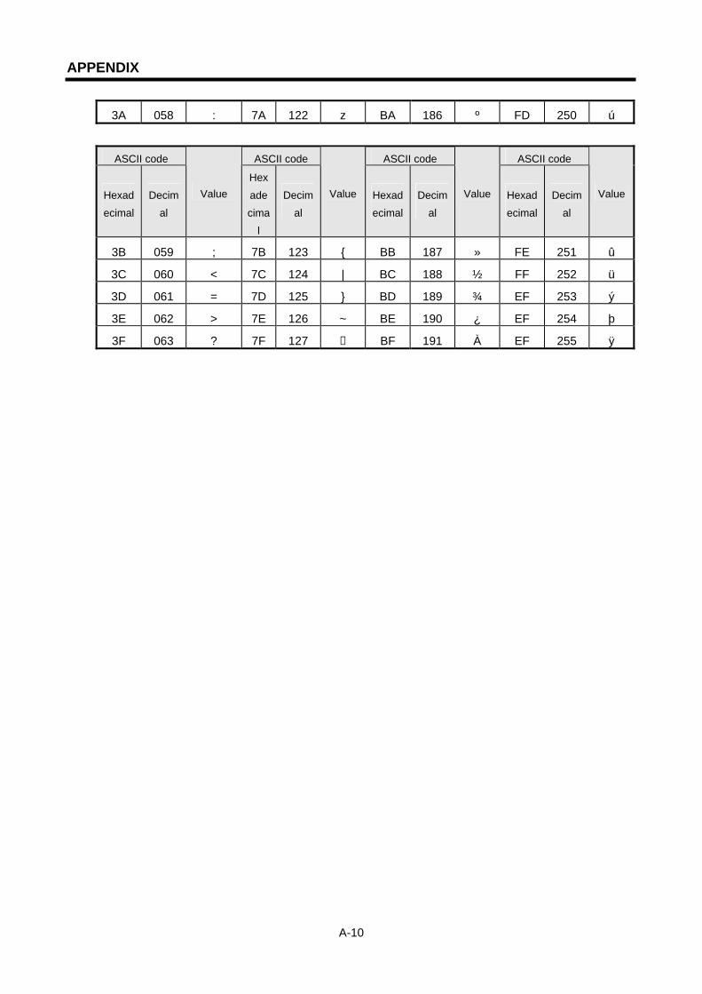
APPENDIX
A-10
3A 058 : 7A 122 z BA 186 º FD 250 ú
ASCII code ASCII code ASCII code ASCII code
Hexad
ecimal
Decim
al
Value Hex
ade
cima
l
Decim
al
Value Hexad
ecimal
Decim
al
Value Hexad
ecimal
Decim
al
Value
3B 059 ; 7B 123 BB 187 » FE 251 û 3C 060 < 7C 124 | BC 188 ½ FF 252 ü 3D 061 = 7D 125 BD 189 ¾ EF 253 ý 3E 062 > 7E 126 ~ BE 190 ¿ EF 254 þ 3F 063 ? 7F 127 BF 191 À EF 255 ÿ

APPENDIX
A-11
A.4 Ethernet Technology Comparison Table
Technology Speed(Mbps) Transmission media Max. distance
Token Ring 4,16 UTP 100m
10Base-T 10 UTP 100m
10Base-F(Multi Mode) 10 Optic cable Max.2km
10Base-F(Single Mode) 10 Optic cable Max.2.5km
10Base-5 10 Coaxial cable 500m
Ethernet
10Base-2 10 Coaxial cable 185m
100Base-T4 100 UTP 100m
100Base-Tx 100 UTP 100m
100Base-Fx(Multi Mode) 100 Optic cable 412m(Half Duplex)2km(Full Duplex)
Fast Ethernet
100Base-Fx(Single Mode) 100 Optic cable 20km
1000Base-T 1000 UTP 100m
100Base-Fx(Single Mode) 1000 Optic cable 3km
100Base-Fx(Multi Mode) 1000 Optic cable 500m
Gigabit Ethernet
100Base-T 1000 Coaxial cable 25m
100VG-AnyLAN 100 UTP -
ATM 155-622 UTP optic cable -
FDDI(Single Mode) 100 Optic cable 40-60km
FDDI(Multi Mode 100 Optic cable 2km
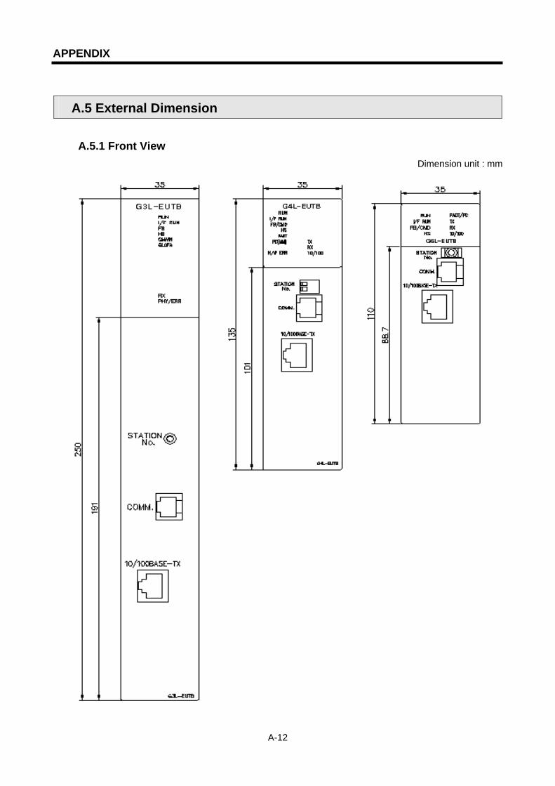
APPENDIX
A-12
A.5 External Dimension
A.5.1 Front View Dimension unit : mm
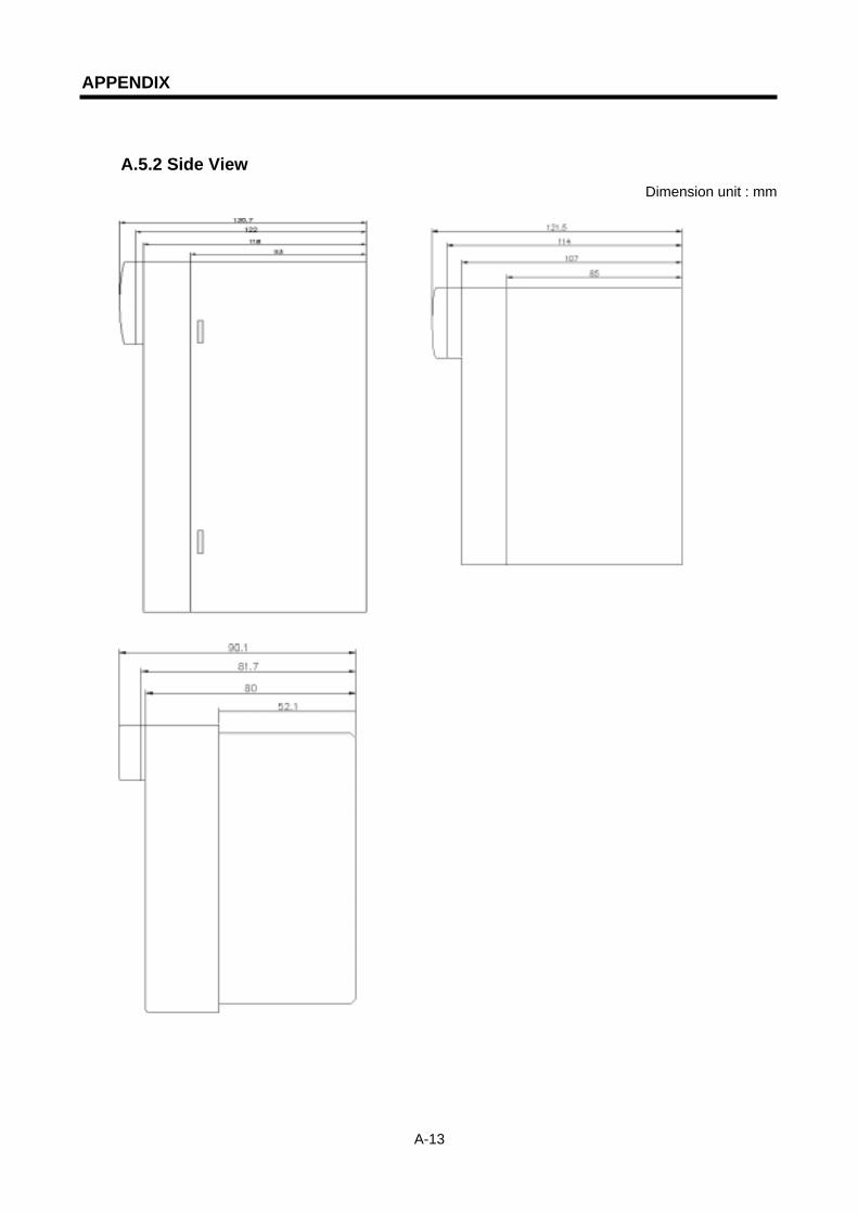
APPENDIX
A-13
A.5.2 Side View Dimension unit : mm
WARRANTY
WARRANTY 1. Warranty Period The warranty period for the purchased product is 18 months from the manufactured date. 2. Warranty Range For problems that occur during the warranty period, a partial replacement or repair is available. But the following
cases are excluded from the warranty range. (1) Problems caused by improper conditions, environment, or treatment other than that described in the
user’s manual. (2) Problems caused by from another manufacturer’s product. (3) Modification or repair outside LGIS or the branches designated by LGIS (4) Used for a method other than the original intended method.
(5) Problems caused by unexpected reasons due to the level of the science technology at the time of the project release.
(6) In the cases that LGIS is not responsible for (such as natural disaster, fire etc.) 3. This warranty means only for the PLC unit body. When using the product, consider the safety precautions for the system configuration or product application.