Section One — Heading 1 - Teledyne Hanson Plus Operation Manual 25-710-800 Rev. O DATE: 23Apr2015....
45
Media-Mate Plus Operation Manual 25-710-800 Rev. O DATE: 23Apr2015 Media-Mate Plus: p/n 25-710-101 Hanson Research Corporation 9810 Variel Avenue • Chatsworth, CA 91311 USA (800) 821-8165 • (818) 882-7266 • FAX (818) 882-9470 www.hansonresearch.com 2014 Hanson Research Corporation This product is covered under one or more of the following US Patents: 3,572,648 4,108,602 4,274,286 5,198,109 5,296,139 5,639,953 5,639,974 5,682,001 6,006,777 6,076,410 6,422,098 Des.377,152 Des.424,458 & Other Patents Pending.
Transcript of Section One — Heading 1 - Teledyne Hanson Plus Operation Manual 25-710-800 Rev. O DATE: 23Apr2015....

Media-Mate Plus Operation Manual
25-710-800 Rev. O
DATE: 23Apr2015
Media-Mate Plus: p/n 25-710-101
Hanson Research Corporation 9810 Variel Avenue • Chatsworth, CA 91311 USA (800) 821-8165 • (818) 882-7266 • FAX (818) 882-9470 www.hansonresearch.com
2014 Hanson Research Corporation
This product is covered under one or more of the following US Patents: 3,572,648 4,108,602 4,274,286 5,198,109 5,296,139 5,639,953 5,639,974 5,682,001 6,006,777 6,076,410 6,422,098 Des.377,152 Des.424,458 & Other Patents Pending.

(blank page)

Media-Mate Plus Operation Manual 25-710-800-O
Table of Contents
What’s New________________________________________________________________________ iii Section One – Safety Considerations ____________________________________________ 1
General ____________________________________________________________________ 1 Safety Markings_____________________________________________________________ 1
Section Two – Introduction _____________________________________________________ 3 Design Features ____________________________________________________________ 3
Section Three – Specifications __________________________________________________ 4 Section Four – How It Works ____________________________________________________ 5 Section Five – Installation ______________________________________________________ 9
Location ___________________________________________________________________ 9 Unpacking _________________________________________________________________ 9 Parts Identification _________________________________________________________ 10 System Check-out __________________________________________________________ 10 Installation ________________________________________________________________ 14 Start Up __________________________________________________________________ 15
Section Six – Validation and Calibration _________________________________________ 16 Pre-Heat Temperature Calibration_____________________________________________ 16 Adjustment of Sensor Display Temperature ____________________________________ 16 Volume Delivery Calibration _________________________________________________ 17 Fine Adjustment of the Delivery Volume _______________________________________ 17 Deaeration Validation _______________________________________________________ 20 Temperature Controller (PID) Set-Up __________________________________________ 20 Temperature Calibration Record ______________________________________________ 21 Volume Calibration Record __________________________________________________ 22 Deaeration Validation Record ________________________________________________ 23
Section Seven – Operating Instructions _________________________________________ 24 Volume Selection __________________________________________________________ 24 Temperature Setting ________________________________________________________ 24 Fill Time Setting ___________________________________________________________ 25 Configuring the Dispense Head ______________________________________________ 26 Media-Mate Plus Interface with Distek 2100 and 2100B ___________________________ 27 Test Cycle ________________________________________________________________ 29
Table of Contents i
Media-Mate Plus Operation Manual 25-710-800-O
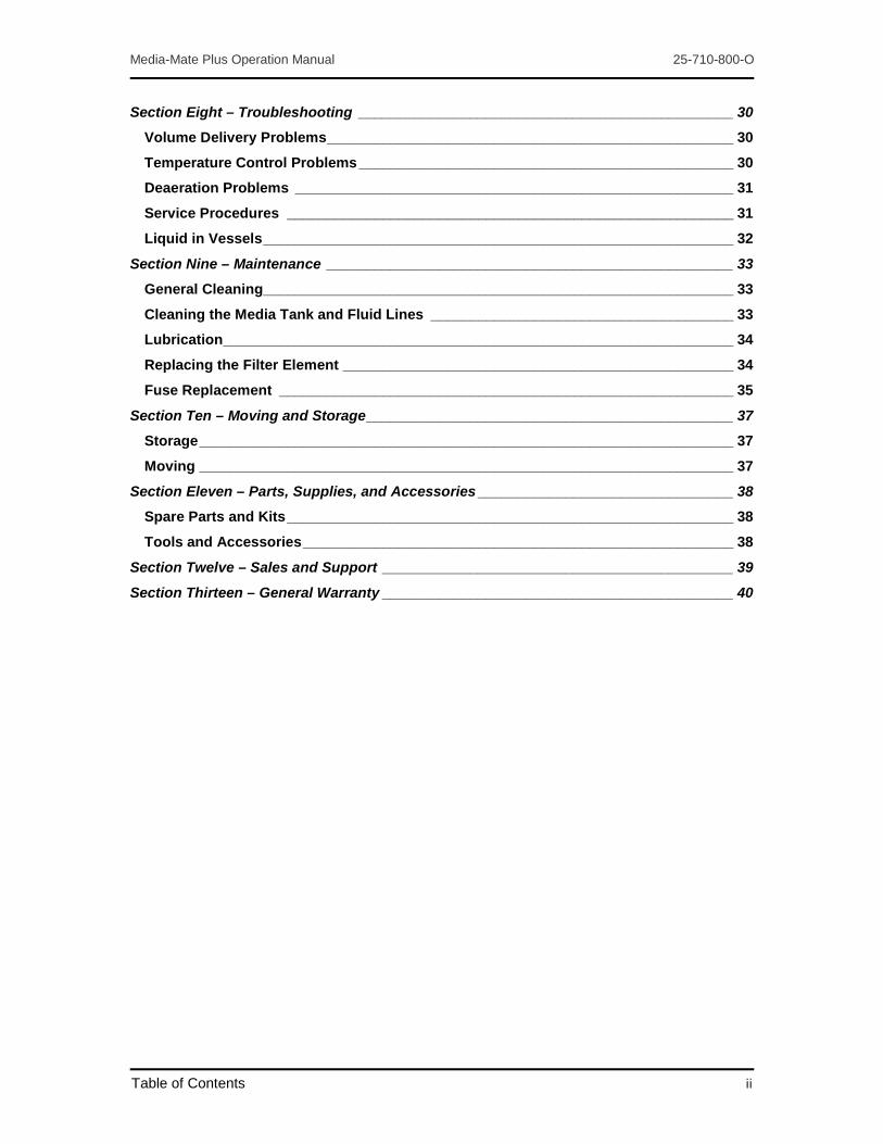
Section Eight – Troubleshooting _______________________________________________ 30 Volume Delivery Problems ___________________________________________________ 30 Temperature Control Problems _______________________________________________ 30 Deaeration Problems _______________________________________________________ 31 Service Procedures ________________________________________________________ 31 Liquid in Vessels ___________________________________________________________ 32
Section Nine – Maintenance ___________________________________________________ 33 General Cleaning___________________________________________________________ 33 Cleaning the Media Tank and Fluid Lines ______________________________________ 33 Lubrication ________________________________________________________________ 34 Replacing the Filter Element _________________________________________________ 34 Fuse Replacement _________________________________________________________ 35
Section Ten – Moving and Storage ______________________________________________ 37 Storage ___________________________________________________________________ 37 Moving ___________________________________________________________________ 37
Section Eleven – Parts, Supplies, and Accessories ________________________________ 38 Spare Parts and Kits ________________________________________________________ 38 Tools and Accessories ______________________________________________________ 38
Section Twelve – Sales and Support ____________________________________________ 39 Section Thirteen – General Warranty ____________________________________________ 40
Table of Contents ii

Media-Mate Plus Operation Manual 25-710-800-O
What’s New
Revision O Section Three - Specifications
Changed Tank Capacities to “about 18 liters”.
Section Seven – Operating Instructions
Changed Temperature Setting to “at least the 18-liters mark.”
Section Eight – Troubleshooting
Changed Temperature Control Problems to “Fill Tank to at least the 18-liter mark.”
Revision M Section Six – Validation and Calibration:
Updated Adjustment of Sensor Display Temperature steps.
Updated new Watlow controller.
Section Seven – Operating Instructions:
Added newer dissolution tester models.
Revision L Section Three – Specifications:
Changed “Media Tank Volume (unusable)” to 2 L to reflect low volume tank upgrade.
Revision K Section Five – Installation:
Added photo of filter housing.
Section Seven – Operation:
Adjusted fill time recommendations for new 0.007” gap fill tubes.
Section Nine – Maintenance:
Added procedure for replacing filter on systems equipped with a filter housing.
Section Eleven – Parts, Supplies, and Accessories:
Added new fill tube to parts list.
Revision J Section Six – Validation and Calibration:
Calibration Gauge Set (p/n 91-902-045) added.
Section Eleven – Parts, Supplies, and Accessories
Numerous spare parts, kits, tools, and accessories added.
Section Twelve – Sales and Support
Hanson Research Corporation contact information and procedure updated.
What’s New iii

Media-Mate Plus Operation Manual 25-710-800-O
Section One – Safety Considerations
General
1. The Instrument should be on its own circuit to prevent problems and circuit overload.
2. Never work on the electrical components in the system while there is power to the Instrument. Disconnect power: Do not run Instrument with the protective cover removed from the electrical control cabinet.
3. Do not fill the tank through the filter port on the tank; the Instrument may not handle the back-pressure.
4. Review all safety and environmental precautions pertaining to any chemicals that are to be used in conjunction with this Instrument.
Safety Markings
For your own safety, you must observe the following safety warning signs. The safety warning signs indicate a possible source of danger and provide preventative information.
Sign Location Safety Warning
Control Panel Caution! Keep media and other liquids away from the control panel and away from all electrical components.
Control Panel Caution! Do not press start switch until indicator lights
are off.
Control Panel Caution! Do not restart Instrument with liquid in flasks
without consulting troubleshooting section.
Interface Panel Heater
Caution: No operator-accessible parts inside. Refer servicing to qualified personnel only. Risk of electrical shock. Do not open. Achtung: Es gibt keine vorn Benutzer zo wanenden Teile. Oberlassen Sie Reparaturen dem qualifizierten Service-fachmann. Hochspannung. Nicht öffnen. Attention: Aucune pièce remplaçable par l’utilisateur. Toute réparation doit être effectuée par un technicien qualifié. Risque d’ electrocution. Ne pas ouvrir.
Interface Panel Caution! Turn Instrument off and remove power cord before replacing fuses. Fuses must be replaced with the same current rating and type described next to the fuse holder.
Heater Caution! Heater is hot; do not touch.
Section 1 Safety Considerations 1

Media-Mate Plus Operation Manual 25-710-800-O
Sign Location Safety Warning
Interface Panel Note! Line and Neutral fused separately.
Inside Control Note! Protective conductor terminal.
Pump Panel Caution! Withdraw power cord to mark prior to plugging into grounded electrical outlet. Withdrawing the full length of the cord may jam the retracting mechanism.
Section 1 Safety Considerations 2

Media-Mate Plus Operation Manual 25-710-800-O
Section Two – Introduction
The Hanson Research Media-Mate Plus is a portable, automatic dissolution prep system. The Instrument will preheat, filter, measure, deaerate and deliver dissolution media to numerous Dissolution Test Stations.
Design Features
1. Portable Cart: The cart is compact and easy to maneuver.
2. Control: The electronics are enclosed within the cart for protection and may be easily removed for service. The control panel is a user-friendly design with digital readout of actual media temperature and temperature set point.
3. Pressure/Vacuum Air Pump: The air pump is enclosed within the cart frame for quiet operation. It is easily removed for service.
4. Dispense Head: The dispense head connects to the dispense tubing with quick disconnects and is user-configurable for filling six or seven dissolution vessels in parallel. The dispense head is designed to interface with the Hanson Research SR-6, SR-8, and SR8-Plus Dissolution Test Stations as well as most test stations made by other manufacturers.
5. Heater Assembly: The heater is an integral design comprised of the heater element, temperature sensor, overload sensor, and level sensor. The heater is easily removed for cleaning or for placement in spare media tanks.
6. Volume Setting: The dispense volume is user-selectable from 250 to 1000 mL in 50 mL increments. The measure system has been factory-calibrated and is easily recalibrated by the user.
7. Media Tank: The tank is chemically inert and is equipped with a 5-micron filter and standard hose bib for quick and easy connection. The tank is easily removed for cleaning or for replacement with spare tanks. A chemically inert cover prevents evaporation and provides a docking location for the dispense head.
8. Retractable Cord Reel: The Instrument is equipped with a 14-gauge, 3-conductor, 20 ft cord-reel.
Section 2 Introduction 3

Media-Mate Plus Operation Manual 25-710-800-O
Section Three – Specifications
Weight
Without media: 67 kg (148 lbs) With 40 liters of media: 107 kg (236 lbs) Size Length: 80.9 cm (31.9 in.) Width: 53.4 cm (21.0 in.) Height: 114.0 cm (44.8 in.) Electrical Voltage: 115 VAC or 230 VAC ± 10% Frequency: 50/60 Hz Current: 13 Amp (115 VAC) or 8 Amp (230 VAC) Phase: single
115 VAC Units 230 VAC Units 4 Fuses (TT Type): One 1/2 Amp, 250 VAC,
One 3/4 Amp, 250 VAC, One 8 Amp, 250 VAC, One 15 Amp.
One 1/2 Amp, 250 VAC, One 3/8 Amp, 250 VAC, One 5 Amp, 250 VAC, One 8 Amp, 250 VAC.
Environment Maximum ambient temperature: 5°C below temperature set point Maximum humidity: < 85 % Performance Cycle time: less than 5 minutes Pre-heat temperature range: 30°C to 45°C Pre-heat temperature control accuracy: ± 0.5°C Pre-heat temperature readout accuracy: ± 0.2°C Pre-heat time (21 to 37 deg C): 60 minutes Delivery volume range: 250 mL to 1000 mL Delivery volume accuracy: ± 1.0 % Deaeration: 95% saturation maximum Filtration: 5 micron nominal NOTE: Accuracy may be improved by fine adjustment (see Section 6 – Fine Adjustment of the Delivery Volume).
Tank Capacities Media Tank Volume (usable): 40 liters (10.5 gal) Media Tank Volume (unusable): 2 liters (0.53 gal) Media Volume to Top of Filter: 8 liters (2.1 gal) Media Volume when low water level sensor turns heater off: about 18 liters
Materials Wet Tank High Density Polyethylene Heater Teflon Coated Filter Polyethylene Flask S.A.N (Styrene/Acrylic/Nitrile) Fittings and Fill Hose PVC Tubing Stainless Steel and Tygon
Section 3 Specifications 4

Media-Mate Plus Operation Manual 25-710-800-O
Section Four – How It Works
The Hanson Research Media-Mate Plus uses a self-tuning PID controller and a Teflon heater to heat the media. Media is moved by low pressure or vacuum and directed by a two-position, multi-channel pinch valve. The media is deaerated by a thin film vacuum process. The media volume is accurately measured by a user-set incremental measuring system. A programmable timer controls the following sequence of events:
1. Fill (Fill Light “ON”) Vacuum draws heated media from the media tank into the measure vessels. The fill time thumbwheel has been set such that actual fill time is sufficient to fill measure vessels slightly above the required volume. The media is deaerated during the fill cycle by thin film vacuum technology.
Figure 4-1
Section 4 How It Works 5

Media-Mate Plus Operation Manual 25-710-800-O
2. Level (Level Light “ON”) Pressure in the measure vessels returns excess media back to the media tank. The volume of media remaining in the vessels is the amount set by the adjustment of the incremental standards.
Figure 4-2
Section 4 How It Works 6

Media-Mate Plus Operation Manual 25-710-800-O
3. Dispense (Dispense Light “ON”) The pinch valve is shifted, opening the dispense lines and closing the fill lines. Pressure in the measure vessels delivers media out the dispense manifold.
Figure 4-3
Section 4 How It Works 7

Media-Mate Plus Operation Manual 25-710-800-O
4. Standby (no lights on) The Instrument is waiting for the operator command to start a cycle. Air flows through the measure vessels and out the fill lines into the media tank. This provides media circulation for optimum temperature control.
Figure 4-4
Section 4 How It Works 8

Media-Mate Plus Operation Manual 25-710-800-O
Section Five – Installation
Location
Environment The media tank temperature must exceed ambient room temperature by at least 5°C for maximum performance of the temperature control system. Therefore, for best results, the ambient temperature should not be allowed to exceed 32°C (90°F) for 37°C tests, or 27°C (81°F) for 32°C tests.
Easy access to a water source and waste disposal for filling and emptying of the waterbath is convenient, although not necessary.
Space The Media-Mate Plus System is designed to be mobile up to 6.25m (20 ft). The laboratory floor should be level and flat to prevent the Instrument from moving when left unattended.
Electrical The Media-Mate Plus System requires a single, grounded electrical outlet, within 5.63 m (18 ft) of the location of the Instrument.
The Instrument is available in two configurations, 115VAC and 230VAC. The voltages are set at the factory and cannot be changed (see model number label on control interface panel next to fuses to determine voltage). The electrical requirements are summarized in Section 3 of this operation manual.
Unpacking
The Media-Mate Plus is shipped fully assembled in one box. The shipping box is specifically designed to provide maximum shipping protection and to facilitate unpacking. The shipping box consists of a lower cardboard tray secured to a pallet with a large box placed over the Instrument. The upper box is strapped to the lower tray and pallet.
NOTE: Shortages or damages must be reported immediately to the freight carrier and to Hanson Research. Notify Hanson Research by telephone (818) 882-7266 or FAX (818) 882-9470.
To Unpack: 1. Move package close to final destination with pallet-moving equipment.
2. Cut and remove straps.
3. Remove upper box taking care not to damage box.
4. Remove Instrument from box.
5. Reassemble empty box and store for possible future use.
Section 5 Installation 9

Media-Mate Plus Operation Manual 25-710-800-O
Parts Identification
Throughout this operation manual, reference is made to various components by name. Figures 5-1 through 5-6 are provided to assist in the visual identification of these components.
System Check-out
1. After removing the Instrument from the box, remove all other shipping materials.
2. Visually inspect the Instrument for damage or missing parts
3. Remove the Heater Assembly from its shipping position within Tank.
4. Remove Dispense Head (see Figure 5-5) from shipping position within Tank, remove from bubble pack, and place as shown.
5. Ensure filter housing has slots facing down.
6. Visually inspect all electrical and pneumatic connections at Interface Panel.
7. Review Operating Instructions. (see Section 7)
Figure 5-1
Section 5 Installation 10

Media-Mate Plus Operation Manual 25-710-800-O
Figure 5-2
Figure 5-3: Control Panel
Section 5 Installation 11

Media-Mate Plus Operation Manual 25-710-800-O
Figure 5-4: Interface Panel
Figure 5-5
Section 5 Installation 12

Media-Mate Plus Operation Manual 25-710-800-O
Figure 5-6 Filter Housing Assembly
Note: The filter housing assembly will function best if the slots are facing the bottom of the tank.
Removed from tank to provide clear view. Clear Filter housing shown only to provide clarification on function.
Section 5 Installation 13

Media-Mate Plus Operation Manual 25-710-800-O
Installation
CAUTION The Instrument should not be plugged in until installed as per the instructions below.
1. Clean the inside of the Tank as necessary to remove any packing debris and fill with approximately 40L of DI water (see Section 9 – Cleaning the Tank and Fluid Lines).
2. Install the Heater Assembly into the Tank as shown (see Figure 5-2). Place Tank Cover onto Tank (see Figure 5.5).
CAUTION The filled Tank is heavy and solution may spill. This installation requires two people. The person holding and pushing the Tank onto the Cart legs should be capable of supporting the weight of the Tank.
3. One person aligns the Media-Mate Plus cart legs with steps on Tank from the back. Tip the Tank just enough so that the Cart legs can be pushed under the Tank. Lift the opposite side of the Tank and push as you slide the Cart legs under.
HINT: Keep the front wheels of the Cart straight.
4. Remove the Fill Hose Assembly from its holding position on the side of the Tank and connect to the Fill Manifold (see Figure 5-2).
5. Connect the Heater connector into the Interface Panel (see Figure 5-4).
6. Connect the Dispense Tubing to the Dispense Head and position over the holes in the Tank Cover (see Figure 5-5).
NOTE: Configure the Dissolution Test Station Vessel Pattern (see Section 7 – Configuring the Dispense Head).
Section 5 Installation 14

Media-Mate Plus Operation Manual 25-710-800-O
Start Up
CAUTION The voltage indicated on the Media-Mate Plus System must be the same as the power source. If the incorrect voltage is indicated, do not plug in the Instrument and contact Hanson Research immediately.
CAUTION Do not press the Start Switch until the indicator lights are off as this may cause overfilling of the System.
The Instrument must be plugged into a grounded power outlet.
1. Pull the power cord out of the retractable cord reel and plug the other end of the power cord into a grounded three-prong power outlet.
NOTE: The power cord plug may need to be replaced for some countries’ power outlet configurations. Ensure that the replacement plug is approved and properly rated for voltage and amperage by following the Power Cord Color Code below:
USA Color Code
Wire Description
International Color Code
Black Live Brown
White Neutral Light Blue
Green Ground Green with Yellow Stripe
2. Turn on the Main Power Switch, located on the Pump Panel next to the power cord outlet.
3. Turn on the Air Pump and Heater power switches, located on the Control Panel.
4. Run a Test Cycle (see Section 7 – Test Cycle) while observing Instrument performance.
5. During the Test Cycle, verify the correct sequence of events by observing the Sequence LEDs on the Control Panel and by visually observing fluid flow at the measure vessels.
6. During the Test Cycle, verify Heater operation by observing the “1” LED on the Temperature Controller (“1” is energized when the Heater is on).
7. Turn off the Heater and Air Pump switches.
8. Turn off the Main Power Switch and remove the power cord from the grounded three-prong power outlet and return into retractable cord reel.
Section 5 Installation 15

Media-Mate Plus Operation Manual 25-710-800-O
Section Six – Validation and Calibration
Pre-Heat Temperature Calibration
Calibration of the temperature control system is recommended every six months for 32°C and 37°C set points. A Temperature Calibration Log is provided and may be copied for entry of temperature calibration data.
1. Place Calibrated Thermometer (p/n 65-233-401) in the 3/8 in. hole provided in the Tank Cover (hole located furthest from Heater Assembly).
2. Set Temperature Set Point to 32°C (see Section 7 – Temperature Setting) and allow it to stabilize.
3. Record set point temperature and sensor display temperature from the digital display on the Control Panel. Record actual temperature from Calibrated Thermometer.
4. Set Temperature Set Point to 37°C (see Section 7 – Temperature Setting) and allow it to stabilize.
5. Record set point temperature and sensor display temperature from the digital display on the Control Panel. Record actual temperature from Calibrated Thermometer.
Adjustment of Sensor Display Temperature
CAUTION The sensor display temperature has been adjusted at the factory and should not require any additional adjustment. Adjustment may be made only when Calibration indicates more than 0.2°C difference between Display Temperature and Actual Temperature (see Section 6 – Pre-Heat Temperature Calibration).
1. Press both the Up (↑) and Down (↓) keys simultaneously until you see “LOC” equal to “5” (if “2”, change number using Up key to “5”).
2. Press the (∞) key, then press the key repeatedly until you see “i.CA”.
3. Add or subtract to the number in order to equal the standard temperature.
4. After calibrating, press the (∞) key, then press both the Up (↑) and Down (↓) keys simultaneously until you see “LOC”, which needs to be changed to “2”. Press the (∞) key to finish.
5. Recalibrate per Section 6 – Pre-Heat Temperature Calibration.
Section 6 Validation and Calibration 16

Media-Mate Plus Operation Manual 25-710-800-O
Volume Delivery Calibration
Calibration of volume delivery is recommended for all volume settings that will be used. Recalibration is recommended every six months for each setting used. Recalibration is also required whenever the delivery volume has been fine adjusted (see Section 6 – Fine Adjustment of Delivery Volume). To facilitate volume calibration, Hanson Research recommends the Volume Calibration Kit (p/n 25-710-705).
1. Set Volume to desired increment (see Section 7 – Volume Selection).
2. Hanson Research recommends performing volume calibration at room temperature. Set temperature control to the desired temperature and allow the media temperature to stabilize (see Section 7 – Temperature Setting).
3. Place the Dispense Head over pre-numbered, plastic vessels (ref. p/n 25-710-705).
4. Start the Media-Mate Plus cycle (see Section 7 – Operating Instructions).
5. Using a calibrated laboratory scale, tare with empty vessel, weigh filled vessels, and record the actual media weight of the delivered volume for each vessel.
6. Empty and dry the vessels and repeat Steps 1 through 5 for a total of 5 cycles.
7. Calculate and record the media volume for each vessel. The density of the media at the calibration temperature is required for the calculation below.
Media Volume = media weight divided by media density at calibration temperature.
8. Repeat all of the above steps for each incremental volume setting that will be used.
Fine Adjustment of the Delivery Volume (one incremental setting only)
When dissolution rate calculations are corrected for actual mean delivery volumes recorded, it should not be necessary to fine-adjust the delivery volume. For applications that do require a more accurate delivery volume, adjust as follows:
1. Calibrate volume at desired incremental setting (see Section 6 – Volume Delivery Calibration).
2. Review Calibration Data and identify adjusters that require finer adjustment.
3. Fine adjustment is accomplished by accurately adjusting the Pointer position on the Fill Tube (see Figures 6-1 and 6-2). The Pointer must be moved approximately 0.0048 in. per mL of volume delivery change.
EXAMPLE: To change delivery volume by 2.5 mL [ 2.5 X 0.0048 = 0.012 ], the Pointer must be moved 0.012 in.
Section 6 Validation and Calibration 17

Media-Mate Plus Operation Manual 25-710-800-O
When delivery volume is too high, reduce by raising the Pointer as follows: 1. Loosen the Upper Lock Screw so that the Fill Tube may be moved. Use 1/4 in. Wrench
(p/n 91-902 037).
2. Using the Micro Drill Blank Set (p/n 91-902-036) or Calibration Gauge (p/n 91-902-045), select a size which corresponds with the required volume change [ Volume Change X .0048 ] or refer to the conversion chart in Figure 6-1.
3. Place the Calibration Gauge or Drill Blank between the Pointer and the upper side of the incremental standard notch (see Figure 6-1).
4. Move the Fill Tube up until the Pointer and Calibration Gauge or Drill Blank are tight against the upper side of the incremental standard notch.
5. Tighten the Upper Lock Screw and remove the Calibration Gauge or Drill Blank.
6. Use 3/4 in. Wrench (p/n 91-902-037) to loosen the Pointer Handle Lock Nut and slide the Pointer up to the top of the incremental standard notch and retighten the Pointer Handle Lock Nut.
7. Loosen the Upper Lock Screw and move the Dispense Tube down until the Pointer is tight against the bottom side of the incremental standard notch and retighten the Upper Lock Screw.
8. Repeat Steps 1 through 7 as necessary for each vessel.
9. Calibrate per Section 6 – “Volume Delivery Calibration.”
Figure 6-1
Section 6 Validation and Calibration 18

Media-Mate Plus Operation Manual 25-710-800-O
When delivery volume is too low increase by lowering the Pointer as follows: 1. Loosen the Upper Lock Screw so that the Fill Tube may be moved. Use 1/4 in. Wrench
(p/n 91-902-037).
2. Using the Micro Drill Blank Set (p/n 92-902-036) or Calibration Gauge (91-902-045), select a size which corresponds with the required volume change [ Volume Change X .0048 ] or refer to the conversion chart in Figure 6-2.
3. Raise the Fill Tube as necessary and place the Calibration Gauge or Drill Blank between the Pointer and the lower side of the incremental standard notch (see Figure 6-2).
4. Lower the Fill Tube so that the Pointer and Calibration Gauge or Drill Blank are tight against the lower side of the incremental standard notch.
5. Tighten the Upper Lock Screw and remove the Calibration Gauge or Drill Blank.
6. Use 1/4 in. Wrench to loosen the Pointer Handle Lock Nut and slide the Pointer down tight against the bottom of the incremental standard notch and retighten the Pointer Handle Lock Nut.
7. Repeat Steps 1 through 6 as necessary for each vessel.
8. Calibrate per Section 6 – “Volume Delivery Calibration.”
Figure 6-2
Section 6 Validation and Calibration 19

Media-Mate Plus Operation Manual 25-710-800-O
Deaeration Validation
Deaeration is validated by running a standard instrument cycle and then measuring the dissolved oxygen content in each filled dissolution vessel. Dissolved Oxygen Meters are readily available from laboratory suppliers such as Cole Parmer, (800) 323-4340.
To avoid dissolution problems, the maximum dissolved oxygen content should not exceed 95% saturation at operating temperature (Handbook of Dissolution Testing, William Hanson, 3rd ed.).
The USP Dissolution Toolkit recommends a dissolved oxygen level of not more than 6 ppm. The Media-Mate Plus will meet this at 37 °C with 500 mL and higher volumes and/or temperatures.
Deaeration Validation must be performed with all user-input adjustments set and recorded on the Deaeration Validation Log. Validation is recommended for each set of user adjustments that will be used. Validation is recommended prior to the first use of the instrument and should be repeated every six months.
1. Set all user-input adjustments (see Section 7).
2. Initiate an instrument cycle (see Section 7 – “Test Cycle”).
3. Using a Calibrated Dissolved Oxygen Meter, measure the dissolved oxygen content in each dissolution vessel.
4. Record all user-input adjustment settings and dissolved oxygen readings on the Deaeration Validation Log.
Temperature Controller (PID) Set-Up
The Temperature Controller (see Figure 6-3) has been programmed at the factory to obtain optimum temperature control and quick heat-up time. The program set points are locked and should not require changing or resetting. If the factory program has been altered for any reason, it may be restored in accordance with Hanson Research Corporation Procedure Number 25-710-807, “Programming Procedures for Temperature Controller.” This procedure is available on request from Hanson Research Corporation (see Section 12).
Figure 6-3: Temperature Controller
Section 6 Validation and Calibration 20

Media-Mate Plus Operation Manual 25-710-800-O
Temperature Calibration Record
Instrument Model Number: Instrument Serial Number:
Set Point Temperature
(°C)
Display Temperature
(°C)
Actual Temperature
(°C) Date Tested By
Section 6 Validation and Calibration 21

Media-Mate Plus Operation Manual 25-710-800-O
Volume Calibration Record
Instrument Model Number: Instrument Serial Number: User Input Settings:
Set Up Number
Media Volume (mL)
Temperature (°C)
Media Density (g/mm)
Fill Time (seconds)
1 2
Delivered Volume (mL) Set-up No. 1 Vessel Identification
Cycle Number
1 2 3 4 5 6 7
1 2 3 4 5
Delivered Volume (mL) Set-up No. 2 Vessel Identification
Cycle Number
1 2 3 4 5 6 7
1 2 3 4 5
Tested By: _____________________________________ Date: _________________
Section 6 Validation and Calibration 22

Media-Mate Plus Operation Manual 25-710-800-O
Deaeration Validation Record
Instrument Model Number: Instrument Serial Number: User Input Settings:
Set Up Number
Media Volume Setting (mL)
Temperature Setting (°C)
Fill Time Setting (seconds)
1 2
Deaeration Reading (percent saturation): Vessel Identification
Set Up Number
1 2 3 4 5 6 7
1 2
Vessel Identification
Set Up Number
1 2 3 4 5 6 7
1 2
Vessel Identification
Set Up Number
1 2 3 4 5 6 7
1 2
Tested By: _____________________________________ Date: _________________
Section 6 Validation and Calibration 23

Media-Mate Plus Operation Manual 25-710-800-O
Section Seven – Operating Instructions
Volume Selection
See Figures 6-1 and 6-2.
1. Loosen the Upper Lock Screw so that the Dispense Tube may be moved.
2. Grasp the Pointer handle and rotate 45° in either direction.
3. Raise or lower the Dispense Tube as necessary to align the Pointer with the appropriate incremental standard notch.
NOTE: The incremental standard has been marked with a volumetric scale so that the appropriate notch may be readily located.
4. Rotate the Pointer handle until the Pointer engages the incremental standard notch.
5. Move the Pointer down tight against the lower side of the notch and tighten the Upper Lock screw.
6. Repeat Steps 1 through 5 for each vessel position.
Temperature Setting
See Figure 5-3.
The Temperature Controller is located in the approximate center of the Control Panel. The Temperature Controller has two digital displays that display in tenths of a degree. The upper display shows actual media temperature while the lower display shows Set Point Temperature.
To Set Temperature: 1. Verify that the media Tank has been filled to at least the 18-liters mark.
2. Verify that the Heater Assembly is installed in the Tank and is plugged into the Interface Panel.
3. Plug the retractable power cord into an appropriate AC power receptacle (see Section 5 – “Electrical” for retracting requirements of cordage).
4. Turn on Heater power and Air Pump power at the Control Panel.
5. Increase or decrease Set Point Temperature using the “UP”/”DOWN” Arrow Keys located just below the Set Point Display on the Temperature Controller. Allow adequate time for the temperature to stabilize.
Section 7 Operating Instructions 24

Media-Mate Plus Operation Manual 25-710-800-O
Fill Time Setting
See Figure 5-3.
The Fill Time Setting determines the amount of time the system will allocate to the Fill Cycle and is dependent on the Delivery Volume Setting. The amount of time allocated must be sufficient to fill the measure vessels 50-100 mL above the Fill Tube slot. The Fill Time is set by adjusting the Fill Time Thumbwheel located on the Control Panel.
Low to Moderate Viscosity Media: 1. Start by setting the Fill Time to the value that corresponds to the Volume Setting in the
table below.
Vol. Setting, mL 250 400 500 600 700 800 900 1000 Fill Time, sec 45 50 55 60 65 70 75 80
2. Run a Test Cycle (see Section 7 – “Test Cycle”) while observing the measure vessels
during the Fill Cycle to see where the fill level is with respect to the Fill Tube slot. The test media must have the same approximate viscosity as the Dissolution Media that will be used.
3. If the actual Fill Level is too high, reduce the Fill Time. If the actual Fill Level is too low, increase the Fill Time.
4. Repeat Steps 2 and 3 until the desired characteristics are achieved.
High Viscosity Media: For high viscosity media it may be necessary to set the Volume Adjustment to one half the desired delivery volume and run two cycles.
1. Set Volume Adjustment to one half the desired delivery volume.
2. Set the Fill Time to two times the value that corresponds to the Volume Setting in the table above.
3. Run a Test Cycle (see Section 7 – “Test Cycle”) while observing the measure vessels during the Fill Cycle to see where the Fill Level is with respect to the Fill Tube slot. The test media must have the same approximate viscosity as the Dissolution Media that will be used.
4. If the actual Fill Level is too high, reduce the Fill Time. If the actual Fill Level is too low, increase the Fill Time.
5. Repeat Steps 3 and 4 until the desired characteristics are achieved.
Section 7 Operating Instructions 25
Media-Mate Plus Operation Manual 25-710-800-O
Configuring the Dispense Head
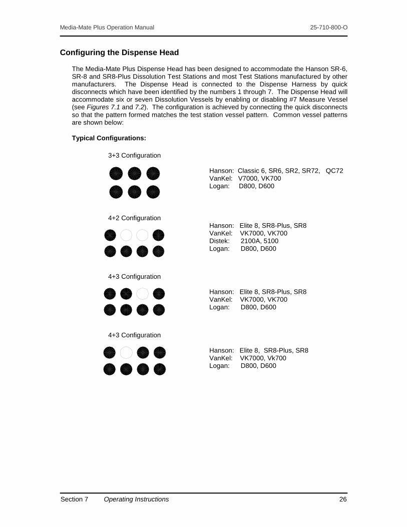
The Media-Mate Plus Dispense Head has been designed to accommodate the Hanson SR-6, SR-8 and SR8-Plus Dissolution Test Stations and most Test Stations manufactured by other manufacturers. The Dispense Head is connected to the Dispense Harness by quick disconnects which have been identified by the numbers 1 through 7. The Dispense Head will accommodate six or seven Dissolution Vessels by enabling or disabling #7 Measure Vessel (see Figures 7.1 and 7.2). The configuration is achieved by connecting the quick disconnects so that the pattern formed matches the test station vessel pattern. Common vessel patterns are shown below:
Typical Configurations:
3+3 Configuration
Hanson: Classic 6, SR6, SR2, SR72, QC72 VanKel: V7000, VK700 Logan: D800, D600
4+2 Configuration
Hanson: Elite 8, SR8-Plus, SR8 VanKel: VK7000, VK700 Distek: 2100A, 5100 Logan: D800, D600
4+3 Configuration
Hanson: Elite 8, SR8-Plus, SR8 VanKel: VK7000, VK700 Logan: D800, D600
4+3 Configuration
Hanson: Elite 8, SR8-Plus, SR8 VanKel: VK7000, Vk700 Logan: D800, D600
Section 7 Operating Instructions 26

Media-Mate Plus Operation Manual 25-710-800-O
Media-Mate Plus Interface with Distek 2100 and 2100B
Filling Six Vessels: 1. Remove the two fittings labeled “not used” in Figure 7-1 below.
2. Close the two shut-off valves to the seventh vessel at the Media-Mate Plus Dispense Assembly (see Figure 7-2).
Figure 7-1
Filling Seven Vessels: 1. Remove the two fittings labeled “not used” in Figure 7-1 above.
2. Connect the Single Flask Filling Assembly (p/n 25-710-415) to the Media-Mate Plus Dispense Harness, #7 Quick Disconnect.
3. Open the two shut-off valves to the seventh vessel at the Media-Mate Plus Dispense Assembly (see Figure 7-3).
Section 7 Operating Instructions 27

Media-Mate Plus Operation Manual 25-710-800-O
To Configure the Dispense Bar: 1. For Six Vessels: Close the Ball Valve and Pinch Valve at Vessel 7 (see Figure 7-2):
Figure 7-2
For Seven Vessels: Open the Ball Valve and Pinch Valve at Vessel 7 (see Figure 7-3):
Figure 7-3
2. Observe the Dissolution Test Station Vessel Pattern.
3. Arrange the quick disconnects at the Dispense Head to match the observed pattern.
NOTE: For six dissolution vessels, the # 7 disconnect must be connected to an inactive location.
Section 7 Operating Instructions 28

Media-Mate Plus Operation Manual 25-710-800-O
Test Cycle
Test Cycles are accomplished with the Dispense Head positioned on the Media Tank Cover docking position. This arrangement provides for media return back to the Tank during an instrument cycle. Test Cycles are useful for observation of instrument performance.
Running a Test Cycle: 1. Set all user inputs (see Section 7 – “Volume Selection,” “Temperature Setting,” and “Fill
Time Setting”).
2. Position the Dispense Head in the docking position on the Media Tank Cover.
3. Fill the Media Tank with media.
4. Plug the retractable power cord into an appropriate AC power receptacle (see Section 5 – “Electrical” for retracting requirements of cordage).
5. Turn on Air Pump power at the Control Panel.
6. Press the start button on the Control Panel.
Filling Dissolution Vessels 1. Set all user inputs (see Section 7 – “Volume Selection,” “Temperature Setting,” and “Fill
Time Setting”).
2. Fill the Media Tank with media.
3. Plug the retractable power cord into an appropriate AC power receptacle (see Section 5 – “Electrical” for retracting requirements of cordage).
4. Turn on the main power switch, located on the pump panel next to the power cord outlet.
5. Turn on the Air Pump and Heater power switches, located on the Control Panel.
6. Configure the Dispense Head (see Section 7 – “Configuring the Dispense Head”).
7. Place the Dispense Head over the dissolution vessels on the Test Station.
8. Verify that the active output ports on the Dispense Bar engage appropriate vessels on the Dissolution Test Station.
9. Verify the media temperature at the Control Panel.
10. Press the start button at the Control Panel.
11. When the cycle is finished, remove the Dispense Head from the Dissolution Test Station and return to the docking position on the Media Tank Cover.
Section 7 Operating Instructions 29

Media-Mate Plus Operation Manual 25-710-800-O
Section Eight – Troubleshooting
Volume Delivery Problems
1. Dispense Volume is too high or too low.
Cause Solution
Improper Volume Setting Reset (see Section 7).
Improper Volume Adjustment Reset (see Section 6).
Improper Fill Time Setting Reset (see Section 7).
Pressure or Vacuum Leak Check and correct (see Section 8).
Clogged Inlet Filter Replace Element (see Section 9).
Restricted Passage Visually check tubing for kinks.
High Media Viscosity Run two cycles (see Section 7).
Pinch Valve Leaks Check and correct (see Section 8).
2. Fails to completely dispense (media left in measure vessels).
Cause Solution
High Media Viscosity Run two cycles (see Section 7).
Fill Time too High Reset (see Section 7).
Temperature Control Problems
1. Does not heat media (media remains at ambient temperature).
Cause Solution
Power Source Connection Check and correct all electrical connections.
Low Water Level Fill Tank to at least the 18-liter mark.
Blown Fuse Replace fuse (see Section 9). Contact Service if fuse blows again.
Set Point too Low Adjust Set Point higher.
Defective Heater Assembly Check and replace if necessary.
Defective Temperature Controller Check and replace if necessary.
Section 8 Troubleshooting 30

Media-Mate Plus Operation Manual 25-710-800-O
2. Temperature fluctuates more than ± 0.5°C with the Tank filled to at least the 20-liter mark. Note that lower liquid levels may cause readings to fluctuate more than 0.5°C.
Cause Solution
Defective Heater Assembly Check and replace if necessary.
Defective Temperature Controller Check and replace if necessary. Temperature Control Program Changed Check program and fix.
3. Temperature reading does not match calibrated thermometer.
Cause Solution
Unit Not Calibrated Perform Calibration Procedure (see Section 6).
Deaeration Problems
Delivered Media exceeds 95% saturation.
Cause Solution
Improper Fill Time Setting Reset (see Section 7).
Low Media Temperature Increase to 2°C above Test Temperature.
Service Procedures
Pressure or Vacuum Leak: 1. Disconnect Fill Hose at upper hose connection and connect hose to Tank side port.
2. Plug manifold port with hose cap fitting.
3. Connect power cord to power source and turn on power to Air Pump at Control Panel.
4. Apply leak test compound (p/n 91-951-025) to all accessible, sealed connections such as vessel covers and tube fittings.
5. Foaming compound indicates a leak.
6. Turn power off and disconnect instrument from power source.
7. Correct all points of leakage and retest per above Steps 1 - 6 until the System has no leaks.
8. Remove hose fitting cap from Fill Manifold and reconnect Fill Hose.
Section 8 Troubleshooting 31

Media-Mate Plus Operation Manual 25-710-800-O
Pinch Valve Leaks: 1. Set-up and run a Test Cycle (see Section 7 – “Test Cycle”).
2. Remove Tank Cover and observe Inlet Filter Element during the Dispense Cycle.
NOTE: Dispense LED on the Control Panel is energized during the Dispense Cycle.
3. Bubbles emitting from the filter indicate a leaking Pinch Valve Assembly. Call Hanson Research for service (see Section 12).
Liquid in Vessels
If the Instrument is turned off in the middle of a cycle and/or media is left in the vessels, it is important not to start another cycle before emptying the vessels as overfilling can occur.
Emptying the vessels is done by setting the Fill Time to 1 second, placing the Dispense Head back on the Tank, and starting a cycle. The material in the vessels will be dispensed back into the Tank without overfilling the vessels. Remember to reset the Fill Time.
Section 8 Troubleshooting 32

Media-Mate Plus Operation Manual 25-710-800-O
Section Nine – Maintenance
Media-Mate Plus has been designed to be a low maintenance instrument. In general, the instrument is maintained by proper cleaning after use, periodic replacement of the filter element and periodic lubrication of fill tubes.
The Media-Mate Plus has type 316 stainless steel in the liquid flow path. HCl can effect the 316 stainless steel, especially when the solution is left to dry.
When using HCl, rinse the Media-Mate Plus with D.I. water when finished. Do not allow the HCl to set in the unit for long periods of time (4 hours or more). Rinse off any external spillage immediately.
General Cleaning
See Section 5 for identification of parts.
The exterior of the Instrument should be periodically wiped down with a damp cloth. Particular attention should be given to the Volume Adjust Components located on the Dispense Assembly. Frequency of cleaning depends on Instrument usage and operating environment.
Cleaning the Media Tank and Fluid Lines
NOTE: Always unplug the Heater Assembly.
The Media Tank should always be cleaned prior to filling the Tank with new media, or if it will not be used within 36 hours.
Cleaning Method: 1. Disconnect the Fill Tube Assembly at the Fill Manifold and drain the Tank out the Fill Tube.
The side of the Tank housing the Filter Assembly may be shifted off of the Support Rail in order to facilitate more complete draining.
2. Remove the Tank and pour out any remaining media and wipe dry.
3. Replace the Tank and reconnect the Fill Tube Assembly at the Fill Manifold.
4. Fill the Tank with clean DI water and run a couple of Test Cycles (see Section 7 – “Test Cycle”).
5. Repeat Steps 1 - 3.
6. With the Tank empty, run two dry Test Cycles (see Section 7 – “Test Cycle”). This will help dry the fluid passages and leave the Instrument ready for the next usage.
7. If the Instrument is not going to be used within 15 days, it should be covered and moved to an appropriate storage location.
Section 9 Maintenance 33

Media-Mate Plus Operation Manual 25-710-800-O
Lubrication
The Fill Tubes (see Figure 6-1) should be lubricated every six-months to maintain easy movement and to facilitate easy adjustment of the Volume Setting.
To Lubricate: 1. Adjust the Volume Delivery Setting to 1000 mL (see Section 7 – “Volume Selection”).
2. Apply a small amount of silicone grease (p/n 91-951-004) to the exterior of the Fill Tubes between the Pointer and the vessel cover.
3. Loosen the upper lock screw and rotate the Pointer in order to disengage the incremental standard.
4. Move the Fill Tube up and down several times between the upper and lower extreme positions.
5. Raise the Fill Tube to the upper position and remove excess grease.
6. Reset Volume Selection (see Section 7 – “Volume Section”).
Replacing the Filter Element
A clogged Filter Element will restrict media flow and impair Instrument performance. The Filter Element should be replaced every 90-days or whenever the Fill Level is reduced by 25 mL (this may be observed during the Fill Cycle). Also, since the Filter Element will retain a small volume of media, it must be replaced whenever the Tank is to be filled with a media that is different than the media that was previously used.
Replacing the element for units without a filter housing: 1. Unscrew the Filter Core Assembly and remove it from the Tank along with the Element
and Washers (see Figure 9-1).
2. Discard the Element and replace with a new Element (p/n 91-500-099).
Figure: 9-1
Section 9 Maintenance 34

Media-Mate Plus Operation Manual 25-710-800-O
For systems with a filter housing used to reduce dead volume in the Media-Mate Plus tank, follow the procedure below.
Replacing the element for units with a filter housing: 1. Unscrew the Filter Core Assembly and remove it from the Tank along with the filter, filter
element, and filter housing end caps (see Figure 9-2).
2. Remove the filter housing end caps and slide the filter off the filter core.
3. Discard the old element and replace with a new element (p/n 91-500-099)
4. Slide the new element into the housing and secure with the end caps.
5. Slide the filter core through the assembly.
6. Reinstall the assembly into the Media-Mate Plus tank with the slots of the filter housing facing down.
Figure: 9-2 Note: Removed from tank to provide clear view. Clear Filter housing shown only to provide
clarification on function.
Fuse Replacement
The fuses are located on the Interface Panel of the Control. Each System has four (4) fuses. The amperage is labeled next to the fuse. Notice that the amperage of three of the four fuses is dependent upon the voltage of the System.
CAUTION For continued protection against risk of fire, replace the fuse(s) with the same type and current rating. Do not over-tighten the fuse holder.
To check the fuses and replace a defective fuse:
1. For fuse holders with slot knobs, insert the end of a standard (flat) screwdriver into the slot, push in and slightly turn counter-clockwise to remove the holder.
Section 9 Maintenance 35

Media-Mate Plus Operation Manual 25-710-800-O
2. For fuse holders with finger grip knobs, push in and slightly turn counter-clockwise to remove the holder.
3. Visually inspect the fuse to see if it is defective. If you are not sure, use an Ohm meter to confirm.
4. If it is defective, remove the fuse from the holder by pulling it straight out. Replace with a fuse of the same type and rating.
5. Push the fuse back into the Control. Secure the fuse holder by pressing in and slightly turning clockwise.
NOTE: Use a standard (flat) screwdriver for fuse holders with slot knobs.
Section 9 Maintenance 36

Media-Mate Plus Operation Manual 25-710-800-O
Section Ten – Moving and Storage
Storage
If the Media-Mate Plus will not be used for an extended period of time (15-days or more), the power should be turned off and disconnected from the power source. The Instrument should be cleaned (see Section 9), covered, and moved to an appropriate storage location.
Moving
The Media-Mate Plus is a portable System and therefore does not require special consideration when being moved within the same laboratory or building. For shipment to another location, the Instrument should be repackaged in its original shipping container.
Section 10 Moving and Storage 37

Media-Mate Plus Operation Manual 25-710-800-O
Section Eleven – Parts, Supplies, and Accessories
Spare Parts and Kits
25-710-701 Two-Year Spare Parts Kit, 115/230V 25-710-125 Stand Alone Temperature Control, 115V 25-710-126 Stand Alone Temperature Control, 230V 25-710-400 Extra 40-liter Tank Assembly with Heater, 115V 25-710-401 Extra 40-liter Tank Assembly with Heater, 230V 25-710-723 Filter Element, 5-micron (pack of 5) 25-710-404 Fill Hose Assembly 25-710-706 Fuse Kit, 115V 25-710-707 Fuse Kit, 230V 91-601-219 Female Quick Disconnect Fitting 91-601-220 Male Quick Disconnect Fitting 25-710-507 Connector 25-710-569 Nipple Fitting, Dispense Head, Gray PVC 25-710-511 Incremental Standard 25-710-514 Pointer 25-710-408 Standoff Assembly, ¾” (1 per clamp; requires 7 per system) 25-710-409 Standoff Assembly, 3/8” (1 per clamp; requires 7 per system) 25-710-515 Fill Tube (0.025” gap) 25-710-577 Fill Tube (0.007” gap) 25-710-524 Dispense Tube 25-710-556 Support 25-710-130 Heater Replacement Kit, 115V 25-710-131 Heater Replacement Kit, 230V 91-601-237 Fitting, ¼” Male x ¼” Female, Stem Elbow 91-425-004 O-Ring, ¼” 91-212-059 Water Level Switch 91-217-021 Over-protection Sensor 91-600-014 Tygon Tubing, 1/8” x ¼” (sold per foot; 70 ft per unit) 91-600-020 Tygon Tubing, 3/16” x 5/16” (sold per foot; 40 ft per unit) 91-601-230 Fitting, 1/8-MPT x 1/8-B, Straight 91-601-231 Fitting, 1/8-MPT x 1/8-B, Elbow 93-670-018 Nut, Acorn, ¼-20, Stainless Steel 25-710-725 Tubing Replacement Kit, Media-Mate Plus
Tools and Accessories
25-710-449 Flask Holding Stand for 8 Vessels 91-902-020 Electro-Mechanical Tool Kit 91-902-013 Tool, Allen Key Wrench, 7/56” 91-902-037 Tool, Wrench, ¼” 91-951-004 Silicone Grease (1 tube) 91-951-025 Leak Test Compound 91-030-003 Vessel, Plastic 65-233-401 Certified Calibrated Thermometer 65-233-402 Certified Calibrated Digital Thermometer 25-710-415 Single Flask Filling Assembly 91-902-045 Calibration Gauge Set
Section 11 Parts, Supplies, and Accessories 38

Media-Mate Plus Operation Manual 25-710-800-O
Section Twelve – Sales and Support
The Media-Mate Plus is sold and serviced by a worldwide network of dealers and distributors. If you need additional accessories, replacement parts, or require service information, you may either contact your local agent, or you can contact Hanson Research Corporation at our worldwide headquarters:
Hanson Research Corporation
Corporate Headquarters
9810 Variel Avenue Chatsworth, CA 91311 USA P: 818.882.7266 or 800.821.8165 (toll-free) F: 818.882.9470
Web Site
www.hansonresearch.com
Sales Support
For quotes, literature, and sales assistance in the USA and worldwide, please email: [email protected].
Customer Support
To place an order, obtain an order’s status, or request a return authorization, please email: [email protected].
Technical Support
For assistance with applications and other technical support and service questions, please email: [email protected], or fill out a Technical Support Request form: www.hansonresearch.com/tsr.htm.
When contacting Hanson Research, please help us eliminate duplication of effort amongst personnel and departments by directing your inquiry to one department or representative.
Section 12 Sales and Support 39

Media-Mate Plus Operation Manual 25-710-800-O
Section Thirteen – General Warranty
Hanson Research Corporation (HRC) products are warranted for one full year including parts and labor. Service contracts and Preventative Maintenance contracts are available for post-warranty support. International dealer warranties may vary. HRC makes no warranty, expressed or implied, for glassware, consumables or products not manufactured by HRC, as evidenced by nameplate on the item or other designation. HRC will give responsible assistance to buyer in obtaining from the respective manufacturer whatever adjustment is reasonable in light of manufacturer’s own warranty. HRC shall be released from any and all obligations under any warranty, either expressed or implied, if the product covered is repaired or modified by other than its own personnel, or made without written authorization of HRC. There are no other warranties, expressed or implied, and HRC shall not be liable under any circumstances for consequential damages.
Section 13 General Warranty 40