:r-,I - Digital Library/67531/metadc689889/m2/1/high...Initial Specifications for Nuclear Waste...
30
Initial Specifications for Nuclear Waste Package External Dimensions and Materials UCID- 19926 :r-, L I D. W. Gregg W. C. O'Neal September 1983 This is an informal report intended primarily for internal or limited external distribution.'Lhe opinions and bndusions stated are those of the author and may or may not be those of the Laboratory. Work performed under the auspices of the US. Department of Energy by the Lawrence Livermore Laboratory under Contract W-7405-Eng-48. UCID--19926 DE84 002110 I '
Transcript of :r-,I - Digital Library/67531/metadc689889/m2/1/high...Initial Specifications for Nuclear Waste...

In i t i a l Specifications f o r Nuclear Waste Package
External Dimensions and Materials
UCID- 19926 :r-,I L I
D. W. Gregg W. C. O'Neal
September 1983
This is an informal report intended primarily for internal or limited external distribution. 'Lhe opinions and bndusions stated are those of the author and may or may not be those of the Laboratory.
Work performed under the auspices of the US. Department of Energy by the Lawrence Livermore Laboratory under Contract W-7405-Eng-48.
UCID--19926
DE84 002110
I '

I
Portions of this document may be illegible in electronic image products. Images are produced from the best available original dOC!Ument.

.-
Initial Specifications for Nuclear Waste Package External Dimensions and Materials
D. W . Gregg and W. C. O'Neal September 1983
DISCLAIMER
This report was prepared as an account of work sponsored by an agency of the United States Government. Neither the United States Government nor any agency thereof, nor any of their employees, makes any warranty, express or implied, or assumes any legal liability or responsi- bility for the accuracy, completeness, or usefulness of any information, apparatus, product, or process disclosed, or represents that its use would not infringe privately owned rights. Refer- ence herein to any specific commercial product, process, or service by trade name, trademark, manufacturer, or otherwise does not necessarily constitute or imply its endorsement, recom- mendation, or favoring by the United States Government or any agency thereof. The views and opinions of authors expressed herein do not necessarily state or reflect those of the United States Government or any agency thereof.
NOTleE PORTIONS QF THIS WEPORT ARE !LkEG!BJlf.
It has been reproduced from tke blest ,available copy to permit the broadest po?sibJ,e. _ _ _ , - -. avafl?b.ility. - - - - - . . rd .I
!
I

ABSTRACT
. .
Initial specifications of external dimensions and materials for waste
package conceptual designs are given for Defense High Level Waste (DHLW),
Commercial High Level Waste (CHLW) and Spent Fuel (SF). The designs have been
developed for use in a high-level waste repository sited in a tuff media in
the unsaturated zone.
conceptual designs are presented for each waste form for both vertical and
horizontal emplacement configurations. Four metal all.oys: 304L S S , 321 S S ,
316L SS and
carbon steel was selected for horizontal borehole liners, and a preliminary
packing material selection is either compressed tuff or compressed tuff
Drawings for reference and alternative package
Incoloy 825 are considered for the canister or overpack; 1020
containing iron bearing smectite clay as a binder.

In i t i a l Specifications for Nuclear Waste Package
External Dimensions and Materi a1 s
by
D. W . Gregg and W . C. O'Neal
September, 1983
Introduction:
The Nevada Nuclear Waste Storage Investigations (NNWSI) Project for
disposal of high level nuclear waste is part of the U.S. Department of
Energy's Civilian Radioactive Waste Management (CRWM) Program. Lawrence
Livermore National Laboratory ( L L N L ) , a participant i n the NNWSI project, i s
developing multibarriered waste packages fo r the disposal of spent fuel (SF),
commercial high-level waste (CHLW) , and defense high-level waste (DHLW) i n a
tu f f repository located deep underground i n the unsaturated zone a t Yucca
Mountain on the Nevada Test S i t e '(NTS). The f ina l engineered barrier system
design may be composed of a sol idif ied waste form, canister, overpack,.
borehole l iner , packing material, and the near f ield host rock, or some
combination thereof. LLNL i s responsible f o r modeling and tes t ing of the
waste forms and barriers as well as for the design, modeling and performance
analysis of the waste packages. T h i s report presents the i n i t i a l
specifications for the external dimensions ( w i t h i n - + 10%) and materials f o r
the waste package conceptual designs. These dimensions will be used as a
basis for the repository conceptual design (by Sandia National Laboratory,
Albuquerque) and f o r entering the preliminary waste package design phase of
the program.

A. Waste Package Dimensions and Materials:
The purpose of this report is to present approximate (within 10%) external
dimensions as well as a carefully selected list of candidate materials that
are being considered for the primary (300 to 1,000 year life) containment
barrier for high level nuclear waste packages.
different waste package designs are summarized in Table 1.
designs are for two basic emplacement configurations: 1) vertical emplacement
of individual packages in holes drilled vertically in the floor of drifts, and
2) horizontal emplacement of multiple packages in much longer holes drilled
horizontally from drift walls. The horizontal holes .may have a carbon steel
liner to keep the hole open during emplacement and retrieval operations, but
it is believed that such a liner is not necessary for the vertical holes.
Vertical emplacement is the reference empl acement configuration for a1 1 the
package designs.
The overall dimensions of the
The package
The waste package designs accommodate three basic types of high level
waste: Defense High Level Waste (DHLW), Commercial High Level Waste (CHLW) and
Spent Fuel (SF).
poured into a stainless steel pour canister. The reference design is pour
canisters emplaced directly into vertical bore holes with no further corrosion
resistant barriers. In this case, the stainless steel pour canister would
serve as the 300 to 1,000 year containment barrier. The alternative designs
consist of placing the pour canisters inside overpacks which are designed to
be the primary containment barrier.
considered because we do not yet have sufficient corrosion information for the
Both DHLW and CHLW are in the f‘orm of glass which has been
The alternative design is being
pour canister to determine if it would be an acceptable containment barrier.
The particular concern is that the thermal cycle associated with the glass
pouring operation could result in the canister being highly stressed.(l) This
2 . ..

Table 1
Pr imary Features of Waste Package Designs
Draw i n g Waste Package Can is te r Overpack P ac k i ng Stee l No. Form Power-W Dia. & Dia. & Mater i a1 Hole
(10 year Length Length Thickness L i n e r o l d) (cm) ( 4 (cm) I D
( 4
83-106352-
83-1 06379- V e r t i c a l
Hor i zon ta l
Ver t i c a l
Hor izon ta l
V e r t i c a l
Hor i zon ta l
Ver t i c a1
Hor i zon ta l
V e r t i c a l
Hor izon ta l
83-1 06376-
83-1 06380-
83-1 06354-
83-106377-
83-1 06375-
83-106378-
83-106386-
83-1 06381 -
82-1 06384-
82-106382- V e r t i c a l
Hor i zon ta l
DHLW 420 , 61 OD None 300 OL
II II . II I1
420 61 OD 65 OD 300 OL . ' 315.8, OL
DHLW
I1 II II I1
, CHLW 2,210 32 OD None 300 OL
II I1 II II
CHLW 2,210 32 OD 36 OD 300 OL 315.8 OL
I1 I I I1 II
SF-BWR, 3,420- 50-68 OD None PWR 3,300 450 max OL
II II I1 I1
SF-BWR, To be 70-80 OD None PWR Deter- 452 max OL.
I1 mined (Packing II
Mater i a1 Conta iner )
3
None None ~
None None
II ' ' 76
None :, None I1 61
None None
II 61
None None
I I 61-76 .
15 None
I 1 95-1 10
. .
... .

stress might alter the canister corrosion mechanism and result in a container
which might not be a satisfactory barrier. In this case an alternative metal
could be selected, or the canister could be placed in an unstressed overpack
which will meet the 300 to 1,000 year containment design requirement.
is also a possibility of minimizing or eliminating canister stresses by
cooling the canister during the pouring operation. However, this may have
disadvantage of increasing the number o f fractures in the glass (which cou
increase its long-term leach rate) and adding complexity to the glass
fabrication process.
The e
the
d
There are two types of spent fuel rods, pressurized water reactor (PWR)
and boiling water reactor (BWR), with a number of different lengths for each.
The reference package design for each of these waste forms consists of
consolidating the rods into a canister which serves as the 300 to 1,000 year
barrier.
pre-consolidated "boxed" fuel rods is also retained because it is anticipated
However, the option of disposing of unconsolidated or
that the repository will retain the capability to accept and directly dispose
of such assemblies without further consolidation at the repository.
Therefore, canister designs are presented for disposal of both consolidated as
well as "boxed" fuel rods. The canisters are placed into the drilled holes
with no additional metal containment barriers. Because the canisters are not
highly stressed (in contrast to the DHLW and CHLW pour canisters) it is highly
probable that they can be designed to meet the 300 to 1,000 year containment
design requirement. without the use of an overpack. This assumes that the
stresses associated with welding on the end caps will be stress relieved, if
necessary.
The need for an alternative design for SF arises not'from the need to meet
the containment design requirement, but rather from the need to meet the long
' 4

term release rate design requirement.
considerably more soluble in water than the DHLW- and CHLW glass. waste forms.
It is thus less likely to meet the post containment period release rate design
Segregated phases within the SF are
requirement. Therefore, the alternative SF designs employ the use of a
packing material which is designed to reduce the release rate after the
canister has corroded through. The present preferred packing material design
employs an outer "container" of packing material, approximately 15 cm. thick,
consisting of either crushed and pressed tuff, or crushed and pressed tuff
containing 515% iron bearing smectite clay as a binder. The packing material
may be prepackaged in a metal container.
Materials Selection:
A total of 17 different metallic materials were reviewed as candidates for
the steel hole liner and the'canister or overpack.(2) From this list'five
materials were selected for further evaluation. The metals that were
initially considered fall under the following categories: austenitic stainless
steels, ferritic stainless steels, titanium alloys, zirconium alloys,
copper-nickel alloys, low-carbon steels, and cast irons. These metals are all
commerc i a1 1 y avai 1 ab1 e.
The selection procedure involved determining and evaluating the properties
considered to be important. These fall under the four general categories:
1. General and Local Corrosion Resistance
2. Required Mechanical Properties
3 . Weldability
4. Material and Fabrication Costs
A detailed description of the selection process is presented in ref. 2.
Four metals were selected for HLW canisters, and overpack materials:
1. AIS1 304L stainless steel,
5
i
i

2. AISI 321 stainless steel
3. AISI 316L stainless steel
4. Incoloy 825 nickel-base alloy
and AISI 1020 carbon steel was selected for horizontal borehole,liners.
A review of packing material functions and candidate materials has been
completed and is in the process of being documented.
spent fuel alternative design, tuff which has been crushed and then highly
As described in the
compressed is one packing material option.
material will not have sufficient strength and density to satisfy
There is a possibility that this
requirements. Therefore, an alternative packing material will consist of
compressing the tuff with a clay binder, iron bearing smectite clay, to give
it more strength. The composition is anticipated to' be approximately 5-15%
clay and 85-95% tuff.
Specific Waste Package Designs:
The DHLW pour canister is 300 cm long and 61 cm OD.(l) Drawings for this
canister emplaced vertically and horizontally are presented in Figures 1 and
2. (Drawing numbers AAA83-106352 and AAA83-106379.) The principal
differences are that the horizontal emplacement configuration uses a steel
hole liner and has multiple packages per hole. The steel hole liner will be
approximately 71 cm ID.
Drawings of this DHLW canister overpacked and' emplaced vertically and
horizontally are presented in Figures 3 and 4.
and AAA83-106380)
of 65 cm and an overall length (including pintle) of 324.5 cm.
liner for the horizontal configuration will be 76 cm ID.
(Drawing numbers AAA83-106376
For this configuration the .overpack has an outside diameter
The steel hole
The CHLW pour canister is 300 cm long and 32 cm OD.(3) It was designed to
have the same length as the DHLW canister and a diameter consistent with the
6
- .. . '. i

emplaced package meeting the temperature design criteria for the waste form.
The diameter was established using preliminary thermal calculations, and it is
anticipated that future thermal calculations will indicate the possibility of
some upward modification of this diameter or for a higher waste loading.
Drawings for this canister emplaced vertically and horizontally are presented
in Figures 5 and 6. (Drawing numbers AAA83-106354 and AAA83-106377) The
principal differences between the drawings are that the horizontal emplacement
configuration has a steel hole liner and has multiple packages per hole. The
steel hole liner will be approximately 61 cm ID.
Drawings of this CHLW canister emplaced vertically and horizontally in I
overpacks are presented in Figures 7 and 8. (Drawing numbers AAA83-106375 and
AAA83-106378.) For this configuration the overpack has an outside diameter of
36 cm and an overall length (including pintle) of 324.5 cm.
1 iner for the horizontal configuration will 'be 61 cm ID.
The steel hole
Drawings of the SF canisters for vertical and horizontal emplacement are
presented in Figures 9 and 10 (Drawing numbers AAA83-106386 and AAA83-106381)
For this canister design a number of diameters and lengths are used to
accommodate BWR and PWR fuel rods both in consolidated and boxed form.
Different diameters accommodate different thermal loading densities for each
configuration. The different lengths (to be tabulated on the drawings) are
needed to accommodate the variety of fuel rod lengths that are used in
different reactors. The diameters of the canisters are tabulated on the
drawings along with the reference length. Tabulated lengths have not yet been
determined.
Drawings of these SF canisters emplaced vertically and horizontally in a
packing material "container" are presented in Figures 11 and 12.
numbers AAA83-106384 and AAA83-106382)
(Drawing
The diameters are tabu1 ated on the
7

drawings along w i t h the reference length. Canister lengths for longer and
shorter fuel rods have n o t yet been determined. For t h i s emplacement mode i t
is planned that the packing material will be preformed and encased i n a s teel
container t o f a c i l i t a t e the emplacement operation. The figures show an
alternative design for the pintle.
The reference pint le design (shown on DHLW and CHLW overpacks) is the same
design a's tha t used for the DHLW and CHLW pour canisters. The alternative
pint le design (shown on the SF canis ters) i s the one used,for t h e spent fuel
disposal t e s t s performed by LLNL a t the Climax mine a t NTS.
6 . Information Supporting Waste Package Dimensions:
1 ) The release r a t e design requirement-as given i n NRC 10 CFR 60 s ta tes :
"60.1 13 Performance of particular barriers a f te r Permanent closure."
engineered barr ier system shall be designed, assuming anticipated processes
"The 1
and events, so that:...the release ra te of any radionuclide from the
engineered barrier system following the containment period shall not exceed
one part i n 100,000 per year of the inventory of tha t radionuclide calculated
t o be present a t 1,000 years following permanent closure, ...p rovided, tha t
th i s requirement does not apply t o any radionuclide which i s released a t a
r a t e less ' than 0.1% of the calculated to ta l release r a t e limit.".(4)
a ) Thermal calculations:
In order t o insure tha t this design requirement i s met i t i s important t o
use a low solubi l i ty waste form. T h i s i s accomplished for DHLW and CHLW by
encapsulating the waste i n t o a low so lubi l i ty glass.
so lubi l i ty can be effectively reduced by keeping intact the highly corrosion
For spent fuel rods,
res i s tan t Zircaloy tubes surroundincj the fuel . T h u s , these waste forms may be
able t o meet the long term release design requirement without any further
protecti'on. However, i t i s essential t o insure tha t the projected low release
a

ra tes are not degraded by the thermal cycle tha t the waste form will
experience i n the repository. The glass i n the DHLW and CHLW pour canisters
can devi t r i fy if he ld a t temperatures which allow crystal nucleation and
growth t o occur, and the Zircaloy tubing encasing the SF can rupture a t
elevated temperatures.
the waste forms does not exceed a c r i t i c a l value.
allowable temperatures for these,waste forms have been estimated and they are
350, 400 and 500 OC fo r SF, CHLW-qnd DHLW respectively.
I t is t h u s important t o insure tha t the temperature of I
Therefore, maximum
. . The maximum temperature tha t will be experienced by the waste form will be
a strong function of the diameter of the waste package and power output of the
waste form. T h u s , the peak temperature can be a c r i t i c a l factor i n
establishing whether a particular diameter and waste package power i s
acceptable or no t . Therefore, calculations of the temperature history of the
waste package components and the surrounding tuff have been in i t ia ted u s i n g a
two dimensional heat t ransfer code, TAC02D.(5) The resu l t s fo r a l l of the
waste package designs are not yet complete, b u t enough calculations have been
done t o indicate that the waste package designs presented here provide
suff ic ient f l e x i b i l i t y so tha t a package can be chosen which will not cause
the waste forms t o exceed the i r maximum allowable temperatures for horizontal
emplacement and an areal oading p f 50,000 watts/acre, assuming a typical s e t
' I
of host-rock thermal properties. The calculations indicated maximum waste
form temperatures of 123(est.), 360, and 340 OC fo r DHLW, CHLW and SF f o r
i n i t i a l thermal powers o f 420, 2210 and 3300 W/WP respectively. These are
below the design c r i t e r i a temperatures fo r each waste form.
recently been in i t ia ted fo r vertical emplacement and they indicate tha t the
maximum waste form temperatures will be s l igh t ly lower fo r vertical
emplacement than fo r horizontal emplacement fo r the same waste package d e s i g n
Calculations have
9
I s

and areal power load.
around PWR SF at 3300 watts per waste package (6 PWR fuel assemblies) shows a
maximum temperature of 380 OC which is above the 350 OC criteria. This
indicates that if packing material is required, a lower power package (smaller
diameter) would have to be used. A calculation of a 40 cm canister with 4 PWR
fuel assemblies (2200 watts) and 15 cm of packing material resulted in a peak
fuel temperature of 325 OC, which meets the temperature requirement.
One calculation with 15 cm of packing material placed
b) Packing Material performance,:
Tne purpose of the packing material is to further reduce the long term
radionuclide release rate in the evkntlthat the low solubility of the waste
form provides an insufficient barrier. The dimensions and materials presented
are still in preliminary evaluation and although they look promising, there is
no firm technical evidence to support their use in an unsaturated tuff
repository.
2) The containment design requirement:
! '
"60.113 Performance of particular barriers after permanent closure."
"The engineered barrier system shall be designed , assuming anticipated processes and events, so that: Containment of HLW within the waste packages
will be su,bstantially complete for a period not less than 300 years nor more
than 1,000 years after permanent closure of the geologic repository."(4)
All the waste package designs rely on a corrosion resistant metal barrier
to meet the containment design requirement.. This primary containment barrier
may either be the canister or the overpack, depending on the specific design.
The thickness of metal needed to meet this design.requirement will depend on
the corrosion rate and mechanism in the actual tuff environment.
corrosion rate and mechanism will depend on a number of parameters including
The
whether the metal is under stress and the type o f metal. At present there is
70

no long term corrosion data for waters equilibrated with tuff which can be
used to estimate the required'wall thickness for. the different metals being
considered. However, there is an additional wall. thickness requirement and
that is the minimum wall thickness that will be required to provide enough
strength for handl'ing the packages. This -th'ickness is estimated to be I
approximately 1 cm.. Taking this into consideration, the metal alloys being
considered should provide at least one candidate that will meet the corrosion t .
requirements and not eiceed the minimum thickness required for hand1 ing.
3 ) The criticality design requirement:
The criticality control requirement states that the waste package will be
designed so that during all handling and emplacement operations, a nuclear
criticality accident is not possible under normal or accident conditions. 1
In
order to satisfy this requirement the calculiited effective multiplication
factor, Keff, will not be allowed to exceed 0.95 for normal handling or
accident conditions. (4)
Criticality calculations have been made on the reference PWR spent fuel
package.
criticality requirement. A flooded package with intact SF rods will be closer
t o criticality, but will probably still meet the requirement.
possible critical conditions is the potential geometry where the package is
The results indicate that dry, intact SF rods will easily meet the
One of the
flooded and the SF rods are no longer intact, with the fuel in a pile at the
bottom of the package. Considerably more analysis will be done to better
evaluate the criticality issue. .
4) The retrieval design requirement:
.
empl acement . (4) The waste package must be readily retrievable for up to 50 years after
In order to meet this requirement the waste package pintles are designed
11

so that they can be used both for initial emp1,acement operations as well as
for retrieval operations. However, a detailed retrieval scenario has not yet
been analyzed.
5) Transportation and hand1 ing- design requirements:
The regulation governing the transport of high-level radioactive materials
is covered in 10 CFR 71.
the shipping container must meet with the waste canister inside. However,
this will mostly affect the desi,gn of the shipping cask. At this point we
This regulation presents numerous requirements that
cannot identify any transportation issues that would require altering the
waste package dimensions and materials presented above.
The handling of the canisters and overpacks outside of the shipping casks
at the repository is covered in 10 CFR 60, which indicates a need for placing
some requirements on their constructi,on to insure that they can be handled
safely.
shipping requirements. However, if ,the shipping requirements are used as a
guide, there will be numerous requirements, a few of which could affect the
dimensions and materials used for the package.
in a preliminary manner, the drop test and the fire test, result from the
requirement that the packages fully contain the waste material under credible
accident conditions.
These handling requirements are not as clearly defined as the
Two that have been evaluated
The drop test requires that the package 'be able to survive a drop of
approximately two times the package length onto an unyielding surface without
breaching. Canisters of similar design have been analyzed and tested for this
drop requirement and the results indicate that the overall dimensions and
materi,als that presented in this report should allow for the. design of a waste
package that will meet this requirement.(6)
\ '
The fire test requires that the waste form canister shall have sufficient
12
UCID-19926 ’ strength such that canister breach due to internal pressure or other,causes
will not occur in the event of a fire of 800 OC and 30 minutes duration.
Calculations of the effect of such a fire on the reference design for a BUR SF
canister indicate that the waste package dimensions and materials being
considered will meet this requirement.
6) Cost effectiveness design requirement:
The waste package should be designed with consideration for cost
effectiveness.(4) A waste package economics code has been developed and used
to estimate the costs of some of the designs presented.
used effectively to evaluate cost trade-offs between different design
variations until more technical performance information is available.
6) Interface design requirements:
However, it cannot be
The waste package designs must interface (be compatible) with all other
A preliminary interface analysis transportation and repository operations.
has been completed and we conclude that at present the waste package designs
are or can be compatible.with transportation and repository operations.
However, a 1 arge portion of the package handling‘facil ities and operations
have not yet been designed in detail. Thus, it is not yet possible to firmly
establish that there are no interface problems.
C. Conclusions:
The initial specifications for waste package external dimensions,
materials and conceptual design configurations given in this report
potentially meet the design requirements presented i n NRC 10 CFR 60 i n so far
as data has been developed to date. However, it will be necessary to develop
considerably more information to confirm this conclusion and more accurately
define the waste package dimensions, materials and designs that are optimum
for disposal at the NNWSI tuff repository.
13

1 R E F ER ENC ES
1. R . G. Baxter, "Description of DWPF Reference Waste Form and Canister",
Savannah River Laboratory Rept. No. DP-1606, June, 1981.
E. i J . Russell, R . E. McCright and W , C. O'Neal, "Containment Barrier
Metals fo r High Level Waste Packages i n a T u f f Repository", Lawrence
Livermore National Laboratory Rept. UCRL-53449, September, 1983.
"Conceptual Waste Package Designs f o r Disposal o f Nuclear Waste i n T u f f " ,
Westinghouse Electric Corporation, Office of Nuclear Waste Isolation Rept.
No. ONWI-439, April, 1983.
10 CFR Part 60, "Disposal of High-Level radioactive Wastes i n Geologic
Repositories: Technical Criteria." Federal Register, June 21, 1983
2.
3.
4.
5. Burns , Patrick J . , "TAC02D-A F i n i t e Element Heat Transfer Code",
UCID-17980 Rev. 2, Lawrence Livermore National Laboratory, January, ,1982.
6. "Canister Final Design Report", Parts 1 and 2 , Westinghouse Electric
Corporation Rept. No. AESD-TME-3047, A u g u s t , 1980.
14

Figure 1
!
NOTES : I . CADDS F I L I N G NAME: T.NC.WASTE.CAN ORA 2.
2. DO NOT SCALE DRAWING.
3. WASTE PACKAGE WEIGHT : 4300 LB. 11950 KGI. 4. T E N -YEAR - C U T - OF -REACT OR
POWER LOAD : 0.42 KW. 300.0 CM
I
1 ; j
I
\ .
71.0, CM z.2.
I
I i ,
i I
1.0 C M A L61.0 CM 0.0. \

Figure 2
t
NOTES : ' I . CADDS F I L I N G NAME: T.NC.WASTE.CAN8 ORA 2 . .
2. DO NOT SCALE DRAWING.
3. WASTE PACKAGE WEIGHT : 4300 L B . I1950 KG.1 THIS DOES NOT INCLUDE THE BOREHOLE L I N E R .
POWER LOAD : 0.42 KW. 4. TEN-YEARS-OUT-OF-REACTOR
1 3 0 0 ' 0 cM:
1.0.
79.
wmsx?n3 61.0 CM O.D.
CM I.D.

Figure 3
1 I -
I
I
1 2
i
1 r-
t
NOTES : I. C A D D S F I L I N G N A M E : T . h t . h ' A S ' Z . C A N 4 394 2.
2. 00 NOT SCALE ORAWIND.
3. WASTE PACKAGE WEIGHT : 5748 LB. 12613 ~ S J .
!
I . 1 7 . 8
308.0 CM-- C M
4. TEN-YEARS-OUT-OF.4En' - jk POWER L O A 0 : 0.42 KW.
I. 0.

Figure 4 I I
~~~~ ~~
NOTES : I. CADOS F I L I N G NAME: T.NC.WPSTE.CAN9 DRA 2.
2. DO NOT SCALE DRAWING.
, 3. WASTE PACKAGE WEIGHT : 5 7 4 8 L B . I2613 KG.1 T H I S DOES NOT INCLUDE BOREHOLE L I N E R .
4. TEN-YEARS-OUT-OF-REACTOR POWER L O A 0 : 0.42 KW.
71.0
'1 . I I.
308.0 C M 7.8 CM
I
i i
I.D. 1
79.0 C M I .
. I i ! I
1
I
* . . . 4 . BOREHOLE L I N E R 3 2 OVERPACK I
' P I N T L E
DEFENSE HIGH L E V E L WASTE CANISTER ASSEMBLY I I I I RLOW SPEC. I O . LLL STOCI IO. I I E Y P I R l NO.

c
t
I 0
9 0 0 m
9 N m
0 J

Figure 6
t
NOTES : I . CAOOS F I L I N G NAME: T.NC.WASTE.CAN6 ORA 2. 2. 00 NOT SCALE DRAWING.
3. WASTE F O R M WEIGHT : 1815 L B . (825 KGI . T H I S DOES NOT INCLUDE BOREHOLE L I N E R .
4. T E N -YEARS-OUT -OF-REACTOR POWER L O A 0 : 2.21 KW.
1 300.0 C M I 61.0 CIA I.: 69.6 C M 1.D.
I
I !
!

Figure 7
i
j 5
I
I
8
i NOTES : I . CADDS F I L I N G NAME: T.NC.WASTE.CAN5 DRA 2. 2. 00 NOT SCALE DRAWING.
3. WASTE PACKAGE W E I G H T : 2532 La. i 1 r 5 1 KG.I
4. T E N -YEARS-OUT-OF -REAC'OR POWER LOAD = 2.21 KW.
300.0 CM -
t i / . .
308.0 CM I 1
e- L
-7.8 CM
3 P I N T L E - 2 OVERPACK
I COMMERCIAL HIGH L E V E L WASTE
I f ! ! CANISTER ASSEMBLY

Figure 8
I
NOTES : I. CADDS F I L I N G NAME: T.NC.WASTE.CAN7 DRA 2.
2. DO NOT SCALE DRAWING.
3. WASTE PACKAGE WEIGHT : 2532 LB. 11151 KG.l THIS DOES NOT INCLUDE THE BOREHOLE L I N E R .
4. T E N -YEARS -OUT -OF -REACT OR POWER LOAD : 2.21 KW.
308.0 CM I I -7 .8 CIA
1 69.0 CM 1.f
_I I I \-O
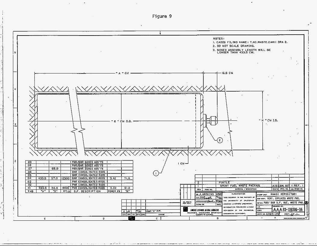
Figure 9
1
NOTES: I. CADDS F I L I N G NAME: T.NC.WASTE.CANII DRA 2. 2. 00 NOT SCALE DRAWING.
3. BOXED ASSEMBLY LENGTH W I L L BE LONGER THAN 433.5 CM.
" CM I.D.
I CM
I I I I I 2 P I N T L E I I
iiru WIT "0. u m w a I cs-xiwriott AIS1 3041 SSTl I REF. I SPENT FUEL WASTE PACKAGE 110n PTC. I O . LLL Slot. 10.
CLASSITICAIION yum ui11 NNHSI REPOSITORY d ,
m. J . W A T K INS (ma1

Figure 10
I
t
NOTES: I. CADDS F I L I N G NAME: T.NC.WASTE.CANI0
2. DO NOT SCALE DRAWING.
3. WEIGHTS GIVEN IN TABLE DO NOT INCLUDE BOREHOLE L INER.
4. BOXED ASSEMBLY LENGTHS WILL BE LONGER THAN 433.5 CM.
d d+ 16.5 C M
** C " CM I.D.
ORA 2.
E l
C
i
i , I I
i
I
I
i i I I
I
I i
1
1 I
I
I I
i

Figure 11 v
N O T E S : I . :REDS r I : INC ~ f i t ~ t . : : . N r . . w w r : ! , 2 OHR :. 4. WASTE PKG. WE I G H T 5 : ABOUT
25.000-30.000 LB. 111337-13605 K G I . 2 . LO N O 1 ! ~ r . l i L E URPwihC.
5. POWER LOAD : TBD. 3. BOYEU ASSEMSL f L E N G T H S W I L L BE L O N G E R THAh 433.5 CM.
" D "
d 0.0.
PERFORATED INNER BACKFILL CON TAlNER
?*I. DOC"",", I. I*< ."0,C.,, 0.
I * L ""l"l"*lll 0. c"11rO""l"
, " " ~ * C C . l " l l " O " < ,".O.".O...
I E

Figure 12
PERFORATED INNER B A C K F I L L CONTAINER
N 0 T E S : I . CRDDS F I L I N G NRnE I T.NC.BRCKFILL-3 DRR I 4. BOXED ASSEMBLY LENGTHS W I L L BE 2. DO NOT SCALE DRAHING. LONGER THAN 433.5 CM.
3. WASTE PKG. WEIGHTS: 25000-3OOOO'LB. 111338-13605 KG.1 5. POWER LOAD : T.B.~. THIS DOES NOT INCLUDE THE BOREHOLE LINER.
N. O.D.
d d , 09 I I I I I PWR/BWR BOXED ASS'YS
07 I I I I I PWRIBWR BOXED ASS'YS 08 I I PWR/BWR BOXED ASS'YS
d 5 M E T A L CONTAINER 4 P I N T L E IALT.1 3 L I N E R 2 COMPRESSED B A C R F I L L
I I I I , P A N ICTCD