
Moving on Up: Remote PHY and What it Means for the … on Up: Remote PHY and What it Means for the...
48
Moving on Up: Remote PHY and What it Means for the Future of Networking Tuesday, May 17 8:00 am – 9:00 am (Eastern Time) Room 157 East – Level 1 Session Chair: Tom Cloonan, ARRIS
Transcript of Moving on Up: Remote PHY and What it Means for the … on Up: Remote PHY and What it Means for the...

Moving on Up: Remote PHY and What it Means for the Future of
Networking Tuesday, May 17
8:00 am – 9:00 am (Eastern Time) Room 157 East – Level 1
Session Chair: Tom Cloonan, ARRIS

The Focus Remote Node / Gateway Actives Passives Headend
Remote MAC & PHY Network Aggregation
Layer (CCAP MLSR or
CCAP OLT) Digital Optics
DAC
ADC
CCAP DS MAC/PHY
CCAP US MAC/PHY
RF Signals
Digital Optics (Optical Ethernet /
G.709 / PON)
Digital Fiber Coax (DFC) Portion of the Network
Edge QAM CMTS CCAP
Broadcast Services Digital
Optics
Digital Optical Transport Shelf
Digital Optics (Optical Ethernet /
G.709 / PON)
Broadband Digital Optional
use of Companding
or Compression
Digital Optics
DAC
ADC
Optional use of
Companding or
Compression RF
Signals
DAC
ADC
RF Signals
Digital Fiber Coax (DFC) Portion of the Network
Remote PHY
Digital Optics
DAC
ADC
CCAP DS PHY CCAP
US PHY CCAP MAC Core
CCAP Remote PMD
MAC (DS)
MAC (US)
Digital Optics RF
Signals
Digital Optics (Optical Ethernet /
G.709 / PON)
Digital Fiber Coax (DFC) Portion of the Network
Impact on Deployment Options, Service Convergence, Redundancy, Virtualization, & PON
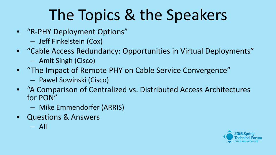
The Topics & the Speakers • “R-PHY Deployment Options”
– Jeff Finkelstein (Cox) • “Cable Access Redundancy: Opportunities in Virtual Deployments”
– Amit Singh (Cisco) • “The Impact of Remote PHY on Cable Service Convergence”
– Pawel Sowinski (Cisco) • “A Comparison of Centralized vs. Distributed Access Architectures
for PON” – Mike Emmendorfer (ARRIS)
• Questions & Answers – All

Q &A

Thank You! Tom Cloonan, Ph.D.
CTO- Network Solutions ARRIS

A Comparison of Centralized vs. Distributed Access Architectures for PON
Michael Emmendorfer Vice President, Systems Engineering and Architecture
ARRIS International PLC May 17, 2016
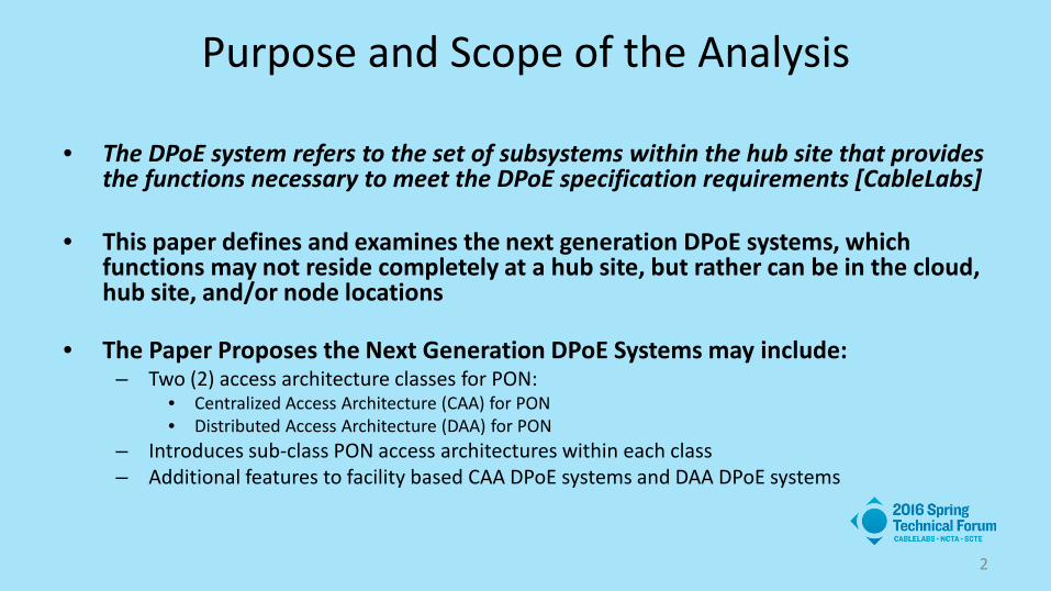
Purpose and Scope of the Analysis
• The DPoE system refers to the set of subsystems within the hub site that provides the functions necessary to meet the DPoE specification requirements [CableLabs]
• This paper defines and examines the next generation DPoE systems, which functions may not reside completely at a hub site, but rather can be in the cloud, hub site, and/or node locations
• The Paper Proposes the Next Generation DPoE Systems may include:
– Two (2) access architecture classes for PON: • Centralized Access Architecture (CAA) for PON • Distributed Access Architecture (DAA) for PON
– Introduces sub-class PON access architectures within each class – Additional features to facility based CAA DPoE systems and DAA DPoE systems
2
3
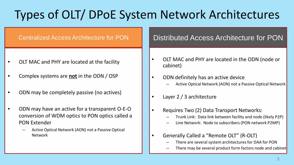
• OLT MAC and PHY are located at the facility
• Complex systems are not in the ODN / OSP
• ODN may be completely passive (no actives)
• ODN may have an active for a transparent O-E-O conversion of WDM optics to PON optics called a PON Extender
– Active Optical Network (AON) not a Passive Optical Network
• OLT MAC and PHY are located in the ODN (node or
cabinet)
• ODN definitely has an active device – Active Optical Network (AON) not a Passive Optical Network
• Layer 2 / 3 architecture
• Requires Two (2) Data Transport Networks: – Trunk Link: Data link between facility and node (likely P2P) – Line Network: Node to subscribers (PON network P2MP)
• Generally Called a “Remote OLT” (R-OLT) – There are several system architectures for DAA for PON – There may be several product form factors node and cabinet
Types of OLT/ DPoE System Network Architectures
Centralized Access Architecture for PON Distributed Access Architecture for PON
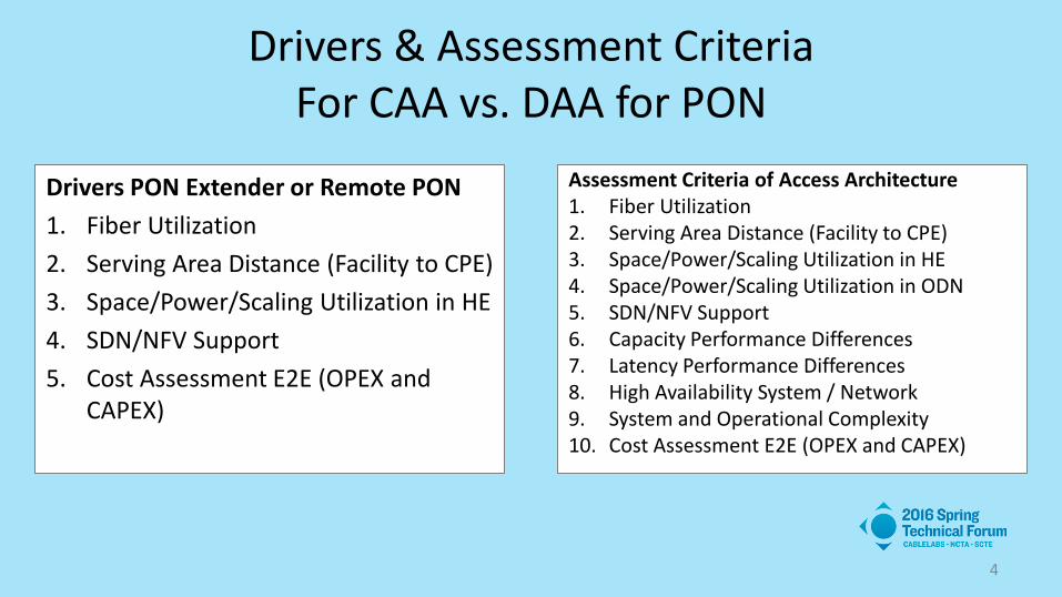
Drivers & Assessment Criteria For CAA vs. DAA for PON
4
Drivers PON Extender or Remote PON 1. Fiber Utilization 2. Serving Area Distance (Facility to CPE) 3. Space/Power/Scaling Utilization in HE 4. SDN/NFV Support 5. Cost Assessment E2E (OPEX and
CAPEX)
Assessment Criteria of Access Architecture 1. Fiber Utilization 2. Serving Area Distance (Facility to CPE) 3. Space/Power/Scaling Utilization in HE 4. Space/Power/Scaling Utilization in ODN 5. SDN/NFV Support 6. Capacity Performance Differences 7. Latency Performance Differences 8. High Availability System / Network 9. System and Operational Complexity 10. Cost Assessment E2E (OPEX and CAPEX)

OLT
DPoE Subsystems
US LTM DS TM
EPON MAC
US UTM
DPoE System
R PE VSI(N)
802 Switch VSI(1)
PBB I-BEB
VE
OSS IP
Network
R P
R PE
R/X
vCM: Virtual Cable Mode R: Router PE: Provider Edge VE: VPLS Edge (Virtual Private LAN Service Edge) VSI: Virtual Switching Instance 802 Switch: Switch based on Layer 2 PBB: Provider Backbone Bridging [802.1ah] I-BEB: I-component backbone edge bridge OLT: Optical Line Terminal DS TM: Downstream Traffic Management US UTM: Upstream Upper Traffic Management US LTM: Upstream Lower Traffic Management Scheduling / Shaping Algorithms / QoS
10G PHY
DPoE Mediation Layer vCM vCM

6
MLSR DPoE Mediation
Layer
US LTM
10G PHY
DS TM
Timing
EPON MAC
VSI(N) 802
Switch
VSI(1) R PE
DPoE Mediation Layer Functions • Mediation between OSS, NMS, and EPON Layers • Virtual Cable Modem (vCM) for registered D-ONU • vCM handles all the OAMP functions for DOCSIS • vCM can proxy requests, signaling, and messages to
the D-ONU using EPON OAM messages • Communicate with D-ONU for provisioning all
required services (e.g. IP HSD, MEF etc.) • vCM Interfaces with System Control Plane for
configuration (e.g. service flow, classifier, and downstream QoS etc.)
• Platform Management Interfaces (CLI, SNMP, etc.)
Downstream Traffic Management (DS TM): • Subscriber Management Filtering (drop) • Classification & Policing (to Service Flow (SF)) • Multicast / Packet Replication • Scheduling / Shaping Algorithms / QoS Priority of SF
(LLIDs)(DOCSIS QoS, MEF Metering / Color Marking) • Packet Counters and Statics (IPDR Raw Data) • DSCP / ToS / TPID (MEF) Overwrite and Translation • CoS Mapping • CALEA / Lawful Intercept
vCM vCM
US UTM
Upstream Upper Traffic Management (US UTM) • CALEA / LI • DSCP / ToS / TPID (MEF) Overwrite • CoS Mapping • Packet Counters and Statics (IPDR Raw Data) • Subscriber Management Filtering (drop) • Cable Source Verify / MAC Learning /Protocol Throttling • Classification & Policing for forwarding toward the NNI
or backplane (aggregate rate limiting)
Upstream Lower Traffic Management (US LTM) • Scheduling / Shaping Algorithms / QoS Priority of LLIDs
(Service Flows) • Dynamic Bandwidth Allocation (DBA) – solicited
scheduling • Token Size per LLID • Polling Interval per LLID • Scheduling / Queuing Algorithm
• Unsolicited Scheduling • MPCP Processing
EPON PHY Layer (Upstream) • FEC • PR-type PMD (PON Optics)
EPON MAC Layer • LLID to VLAN (tunnel ID) • Operation, Administration, and Management (OAM) • Multipoint Control Protocol (MPCP) (Discovery &
Registration, GATE Generation, REPORT Processing, Round Trip Time, LLID / Preamble (Frame Formation)
• Encryption AES 128
Multilayer Switch Router (Control & Data Plane) • Routing • ARP • NDP • IS-IS • OSPF
• MP-BGP • MPLS • VPLS • Layer 2 Encapsulation • Layer 2 Switching
Control Plane
Control Plane Functions • Centralized control for all required configurations (e.g.
port, channel and MC domain etc.) • Centralized control for sending all the collected stats
(e.g. port, channel and mac domain etc.). • EPON MAC for programming all required functionality
(e.g. port, channel, LLID and upstream QoS etc.). • DS TM for programming all required functionality (e.g.
service flow, classifier, and downstream QoS etc.). • Implement the control plane for multicast forwarding
DPoE System Functions
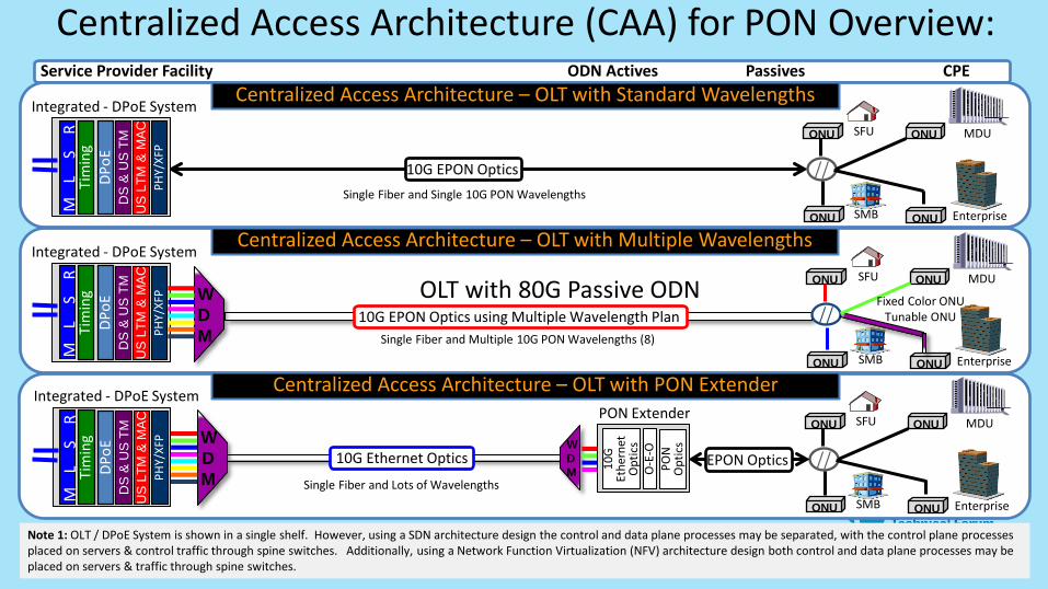
Centralized Access Architecture (CAA) for PON Overview: Passives CPE Service Provider Facility
Centralized Access Architecture – OLT with Standard Wavelengths
ONU ONU
// ONU ONU MDU
ML
SR
DPoE
US
LTM
& M
AC
PH
Y/XF
P
DS
& U
S T
M
Tim
ing
SFU
Enterprise SMB
10G EPON Optics Single Fiber and Single 10G PON Wavelengths
Integrated - DPoE System
7
Centralized Access Architecture – OLT with Multiple Wavelengths
ONU ONU
ONU ONU MDU
ML
SR
DPoE
US
LTM
& M
AC
PH
Y/XF
P
DS
& U
S T
M
Tim
ing
SFU
Enterprise SMB Single Fiber and Multiple 10G PON Wavelengths (8)
Integrated - DPoE System
WDM
10G EPON Optics using Multiple Wavelength Plan // OLT with 80G Passive ODN Fixed Color ONU
Tunable ONU
Note 1: OLT / DPoE System is shown in a single shelf. However, using a SDN architecture design the control and data plane processes may be separated, with the control plane processes placed on servers & control traffic through spine switches. Additionally, using a Network Function Virtualization (NFV) architecture design both control and data plane processes may be placed on servers & traffic through spine switches.
PON Extender
Centralized Access Architecture – OLT with PON Extender
ONU ONU
// ONU ONU MDU
ML
SR
DPoE
US
LTM
& M
AC
PH
Y/XF
P
DS
& U
S T
M
Tim
ing
SFU
Enterprise SMB
EPON Optics Single Fiber and Lots of Wavelengths
Integrated - DPoE System
WDM
10G Ethernet Optics WDM 10
G Et
hern
et
Opt
ics
O-E
-O
PON
O
ptic
s
ODN Actives

8
CPE Service Provider Facility ODN Actives Passives Distributed Access Architecture – Remote PON MAC
US
LTM
&
MA
C
PON
Opt
ics
Tim
ing
L2 /
L3
Remote PON MAC (RPM)
ONU ONU
// ONU ONU MDU
ML
SR
DPoE
Agg
. Sw
itch
PHY/
XFP
DS
& U
S T
M
Tim
ing
SFU
Enterprise SMB
M-OLT Packet Shelf
Single Fiber and Lots of Wavelengths
10G Ethernet + MACsec WDM
EPON Optics
Note 1: M-OLT Packet Shelf is shown in a single shelf. However, using a SDN architecture design the control and data plane processes may be separated, with the control plane processes placed on servers & control traffic through spine switches. Additionally, using a Network Function Virtualization (NFV) architecture design both control and data plane processes may be placed on servers & traffic through spine switches. Note 2: R-OLT is shown using NFV for the DML only and SDN may used as well. Note 3: R-OLT and RDS may use SDN.
MA
Cse
c
MA
Cse
c
Distributed Access Architecture – Remote DPoE System
US
LTM
&
MA
C
PON
Opt
ics
Tim
ing
L2 /
L3
TM
Remote DPoE System (RDS)
DPoE
ONU ONU
// ONU ONU MDU
ML
SR
Agg
. Sw
itch
PHY/
SPF+
SFU
Enterprise SMB
EPON Optics Single Fiber and Lots of Wavelengths
MLSR
WDM
10G Ethernet + MACsec WDM M
AC
sec
MA
Cse
c
EMS
PHY/
SFP+
PHY/
SFP+
Distributed Access Architecture – Remote OLT
US
LTM
&
MA
C
PON
Opt
ics
Tim
ing
L2 /
L3
TM
DPoE
Clie
nt
Remote OLT (R-OLT) DPoE
ONU ONU
ONU ONU MDU SFU
Enterprise SMB
//
ML
SR
Agg
. Sw
itch
PHY/
SPF+
MLSR
Single Fiber and Lots of Wavelengths
10G Ethernet + MACsec WDM
EPON Optics
MA
Cse
c
MA
Cse
c
EMS
PHY/
SFP+
WDM
WDM
Distributed Access Architecture (DAA) for PON Overview:

Summary Assessment of CAA for PON: • CAA enables an All Passive Network (except for PON extender) with 100% of the software in the facility • Centralized Access Architecture – OLT with NG-PON2 Wavelengths
– Optical Options • Full Band Tunable Optics increase one-time capital cost of the solution but yields a passive network for operations • Partial band Tunable may reduce capital compared with full band tunable • Single Wave lowest cost but will impact operations due to management of different colored pluggables or CPE
– Cost Assessment • Will increase at the OLT and ONU compared to nearly all other solutions • Aligning 10G EPON TWDM and NG-PON2 TWDM will drive volumes and will reduces cost • We are exploring many different CPE optical wavelength plans and non-tunable solutions (costs should reduce) • Cost will likely not reach the 10G EPON single wave level
• Centralized Access Architecture – OLT with PON Extender
– Requires active in the outside plant (PON moves to AON – Active Optical Network) – Fiber utilization solved with PON Extender and use of DWDM/CWDM 10G Ethernet optics – Maintains the use of the same 10G EPON 802.3av PON optical wavelengths to the CPE – Distance challenge is solved with spans to ~80 km (between facility and node) – An increase in separation between the “current” OLT PON Scheduler and the ONU reduces upstream link capacity – Maximizes PON port utilization – Cost Compared to CAA PON and DAA need to be examined closely
9

Summary Assessment of DAA for PON: • Requires actives in the outside plant (PON moves to AON – Active Optical Network)
• Maintains the use of the same 10G EPON 802.3av PON optical wavelengths to the CPE
• Space Savings in the Headend (depends and may not be significant)
– Depends on customers per headend aggregation router port (within 2 km allows 128 subs per port) – Non-blocking architecture between HE and node may have marginal HE space savings (vs. PON Extender) – Blocking architecture between HE and node will increase the space savings
• Maximizes – Fiber utilization with use of WDM optics to the DAA for PON device – Fiber distance between facility and customers served to ~80 km or more – PON port utilization because PON closer to subs and blocking architecture may be used
• Costs – The functions required/desired in the Remote PON Device shifts complexity and costs. – Cost Compared to CAA PON and DAA needs to be examined closely
• Differences between the three sub-classes of DAA for PON are examined in the paper
10

What are the Key Differences in CAA PON Extender vs. DAA OLT?
• Fiber utilization are solved by both PON extender and DAA for PON (RPM, R-OLT, or RDS)
• Distance Challenge (facility to subscriber) – Solved by Both PON Extender and DAA for PON (RPM, R-OLT, or RDS) – When PON Extender is used to increase between the “current” OLT PON Scheduler (facility) and the ONU
reduces upstream link capacity. – DAA for PON (any option) typically will have short distance separation between OLT & ONU, thus have higher
capacity and lower latency than any CAA option.
• Space savings in the headend between these options are not significant (DAA is slightly better)
• Overall architectures differences – CAA with PON extender keeps all the software in the facility this is important to some MSOs and within Comcast
engineering and ops like this approach (similar to HFC node) – With 100% of the hardware and software in the facility this means the entire OLT can be part of SDN and NFV – The more that is distributed to the node the less that is part of the NFV
11

Thank You! Michael Emmendorfer
Vice President, Systems Engineering and Architecture ARRIS International PLC
May 17, 2016

REMOTE PHY DEVICE DEPLOYMENT OPTIONS 16 March 2016

2
About ~85% of annual Network Capex is in the Access Network that includes Edge, OSP & CPE, but excludes Backbone & Metro
We satisfy the customer demand growth by managing available plant bandwidth and subscribers sharing the bandwidth
Access Summary
Access network is planned to offer an optimal customer Quality of Experience during peak hours (typically 7 – 10 PM)
Currently carrier additions and node splits are used to meet the speed plan and tier penetration
Engineering Guidelines
DOCSIS 3.1 will enable a 1 Gbps product offer at low penetration rates
A Fiber Deep strategy positions us to leverage our HFC network while maintaining a path to future access technologies (FTTH, FDX…)
DOCSIS 3.1 to 1 Gbps and beyond
EXECUTIVE SUMMARY

NETWORK OVERVIEW
3
Backbone Metro Edge Outside Plant Customer Premise
Resid
entia
l Bu
sines
s
Backbone & Peering
Points
Networks are segmented into five areas – Backbone, Metro, Edge, Outside Plant (OSP), and Customer Premise Equipment (CPE).
Terminates our services in the home & business
Interconnects hub sites to customers
Local distribution point for subscriber content
Aggregation point for the hub sites, local content ingest
Modem, STB, Wi-Fi
CB CPE
Interconnect markets, national content ingest
Access Network Core Metro
Nodes, Amplifiers etc. CMTS, Video Servers, Back Office Aggregation Routers
Optical Line Termination Routers CB Aggregation Routers Fiber, Splitters etc.

BANDWIDTH BASICS
4
The total downstream and upstream bandwidth is shared across all subscribers in a Service Group.
2 4 9 52 58 2 32
D3
.0
Other Data + Voice Reserved Available Digital Video Control D3.0
5 MHz 1 GHz 42 MHz
Downstream Up
6.4 MHz 30 Mbps
6.0 MHz 42.88 Mbps
1D
(*) Example assumes All-Digital in the market
Downstream Bandwidth
Total Bandwidth offered by
1 GHz DOCSIS Spectrum
Total bandwidth is shared across
the Service Group
Avg. bandwidth per Sub.
Total SG Bandwidth
Size of SG =
Upstream Bandwidth
Single Quadrature Amplitude Modulated (QAM) upstream channel is 6.4 MHz wide with a raw capacity of 30 Mbps
Single Quadrature Amplitude Modulated (QAM) downstream channel is 6.0 MHz wide with a raw capacity of 38.8 Mbps
Band
wid
th p
er S
ub
QAM
s in
1 G
Hz M
arke
ts*
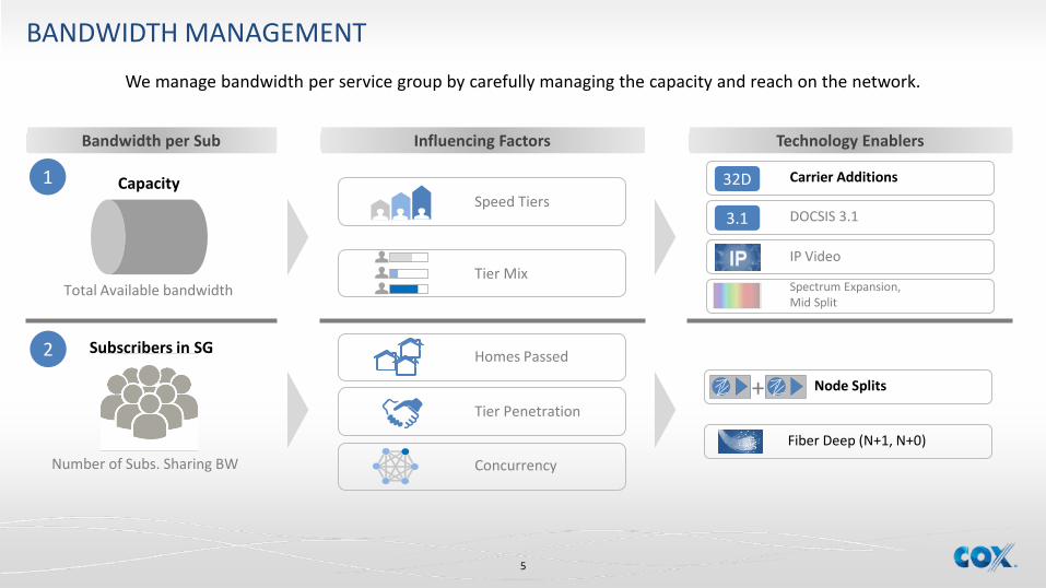
BANDWIDTH MANAGEMENT
5
We manage bandwidth per service group by carefully managing the capacity and reach on the network.
Influencing Factors Technology Enablers Bandwidth per Sub
Total Available bandwidth
Number of Subs. Sharing BW
Capacity
Subscribers in SG
1
2
Tier Mix
Speed Tiers
Concurrency
Homes Passed
Tier Penetration
Carrier Additions
IP Video
DOCSIS 3.1 3.1
32D
Spectrum Expansion, Mid Split
Node Splits
Fiber Deep (N+1, N+0)
+

6
Access Network is defined by the headend equipment (Cable Modem Termination Systems (CMTS), Video QAMs, Back office servers), OSP infrastructure (Node, Amplifiers) and CPE
To metro distribution
CMTS Fiber Node Tap
Amplifier
Tap
Tap
Tap
Customer
Households Passed (HHP) – Number of homes that fall in the serving area of a single fiber node Service Group – Number of customers sharing DS and US bandwidth
Households Passed
+
Fiber
Coax
Fiber
Coax
Coax
Not a customer
Serv
ice
Gro
up
Fibe
r Dee
per Tap N
+5
HHP 512
Tap N+1
HHP 128
Tap N+0
HHP 64
Fiber Fiber
Fiber
Fiber Fiber
Fiber
Fiber terminates at the node
Node plus 5 Amplifiers
Node plus an Amplifier
Node with no Amplifier (passive network)
ACCESS NETWORK

vCCAP HA – Opportunities in Virtual Environments
Amit Singh
Principal Engineer, CTAO Cisco Systems
May 2016

Tunable HA in a vCCAP Environment • Virtual Instance/RPD • 10x - 100 Subs/RPD • Managed as a Single Entity
• Backup Instance N to n:1 • Tunable Time Of Day/Calendar • Tunable By Service Location • Multiple Service Tiers • Repurpose Infrastructure • Flexible Energy Usage

Orchestration
RPDs RPDs RPDs RPDs RPDs RPDs
Server VM1 VM2
Server VM1 VM2
vCCAP Data Center (DC) Instance
HA Manager Remote PHY Device (RPD)

Orchestration Server
RPDs RPDs RPDs RPDs RPDs RPDs
VM1 VM2
Server VM1 VM2
HA Manager
Restart Virtual Machine
• Lowest HA Tier • Simplest • Cheapest • Reestablish RPD tunnels • Reregister Modems

Orchestration Server
RPDs RPDs RPDs RPDs RPDs RPDs
VM1 VM2
Server VM1 VM2
DB DB DB DB
Stateful Restart
• Simplified • Add Storage Infrastructure • Re-establish RPD Tunnels • Modems Reregister
HA Manager
Orchestration
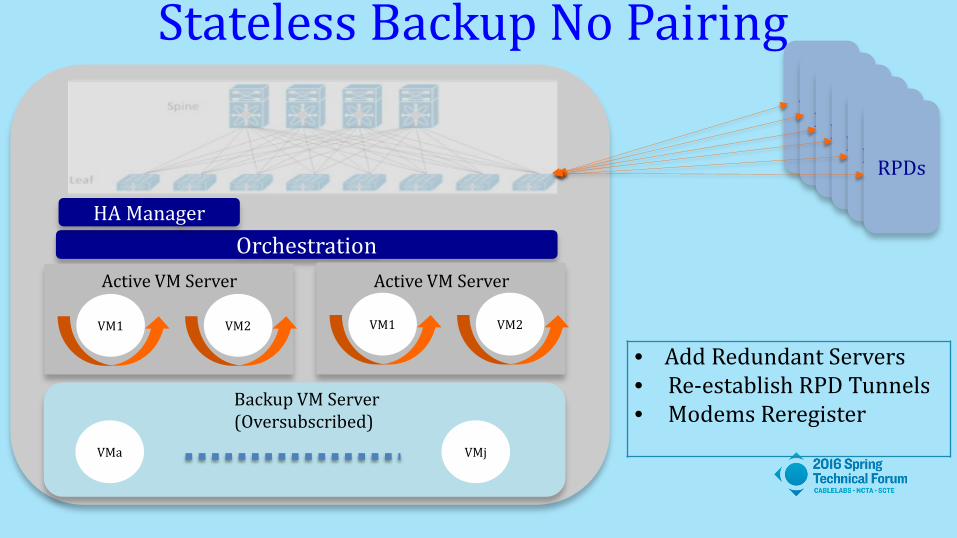
Stateless Backup No Pairing RPDs RPDs RPDs RPDs RPDs RPDs
VM1 VM2
Active VM Server
VM1 VM2
Backup VM Server (Oversubscribed)
Active VM Server
VMa VMj
• Add Redundant Servers • Re-establish RPD Tunnels • Modems Reregister
HA Manager

Orchestration
Stateless Paired Backup RPDs RPDs RPDs RPDs RPDs RPDs
VM1 VM2
Active VM Server
VM1 VM2
Backup VM Server (Oversubscribed)
Active VM Server
VMa VMj
HA Manager
• Add Redundant Servers • Pre-establish RPD Tunnels • Modems Reregister
Orchestration
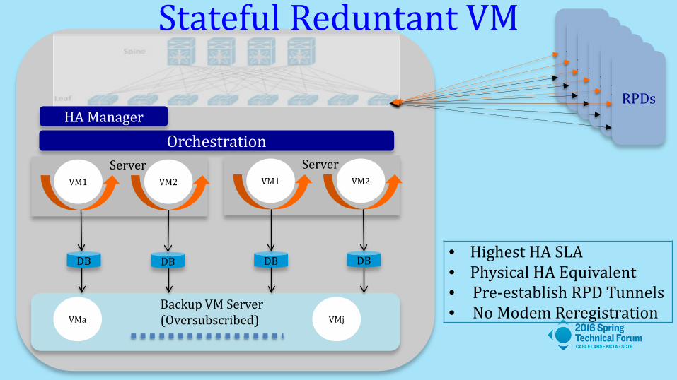
Stateful Reduntant VM RPDs RPDs RPDs RPDs RPDs RPDs
Server VM1 VM2
Server VM1 VM2
DB DB DB DB
Backup VM Server (Oversubscribed) VMa VMj
HA Manager
• Highest HA SLA • Physical HA Equivalent • Pre-establish RPD Tunnels • No Modem Reregistration

vCMTS HA – Disaster Protection 1:1 Disaster Backup VM in Alternate Data Center(s)
Backup VM Server
Active VM Server Active VM1 Active VM2 Active VM3
Backup VM1 Backup VM2 Backup VM3 Backup VM4 Backup VM5
DB
DB
DB Data Center
Active VM Server Active VM2 Active VM3
DB
DB Disaster VM Server Way Over Provisioned
Disaster VM1
Disaster VM2
Disaster VM3
Disaster VM4
Disaster VM5
DB
DB
DB
DB
DB
Data Center

Tunable HA – Lots of Dials!

Thank You!
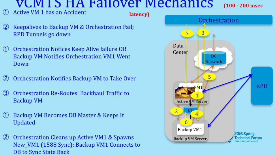
vCMTS HA Failover Mechanics (100 - 200 msec latency) ① Active VM 1 has an Accident
② Keepalives to Backup VM & Orchestration Fail;
RPD Tunnels go down ① Orchestration Notices Keep Alive failure OR
Backup VM Notifies Orchestration VM1 Went Down
② Orchestration Notifies Backup VM to Take Over
③ Orchestration Re-Routes Backhaul Traffic to Backup VM
① Backup VM Becomes DB Master & Keeps It
Updated
② Orchestration Cleans up Active VM1 & Spawns New_VM1 (1588 Sync); Backup VM1 Connects to DB to Sync State Back
Backup VM Server
Active VM Server
Active VM1
Backup VM1
DB
Data Center
Orchestration
DC Network
RPD
4
5
3
2
1
7
6

vCMTS HA Revert Back Mechanics (Backup Server Over Subscribed)
① New_VM1 Initializes & Waits for Hold Over Time (10 mins ?) & the tunnels/keep alives are up & running
② Orchestration Notifies New_VM1 & Backup VM New_VM1 is Going Active
① New_VM1 Notifies RPD Its Going
Active (Assume: RPD Tunnel Switch is Quicker than Orchestration Re-Route)
① Orchestration Re-Routes Backhaul
Traffic to New_VM1
② RPD Starts Sending US Traffic to New_VM1
Backup VM Server
Active VM Server
New_VM1
Backup VM1
DB
Data Center
Orchestration
DC Network
RPD 5
3 1
4
2
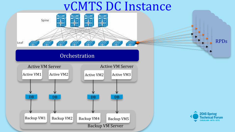
Orchestration
Backup VM Server
Active VM Server
Active VM1 Active VM2
Backup VM1 Backup VM2 Backup VM4 Backup VM5
DB DB
Active VM Server
Active VM2 Active VM3
DB DB
vCMTS DC Instance RPDs RPDs RPDs RPDs RPDs RPDs
The Impact of Remote PHY on
Cable Service Convergence
Pawel Sowinski Principal Engineer, CTAO
Cisco Systems Inc.
May 2016
Agenda • On Friday, May 13th, 2016 MIT Technology Review
published an article entitled: “Moore’s Law Is Dead. Now What?”
• Today, we’ll discuss how three features of Remote PHY architecture help the cable operators deal with access network scaling issues - a result of exponential bandwidth growth, indirectly driven by Moore’s law. • Is it already too late?
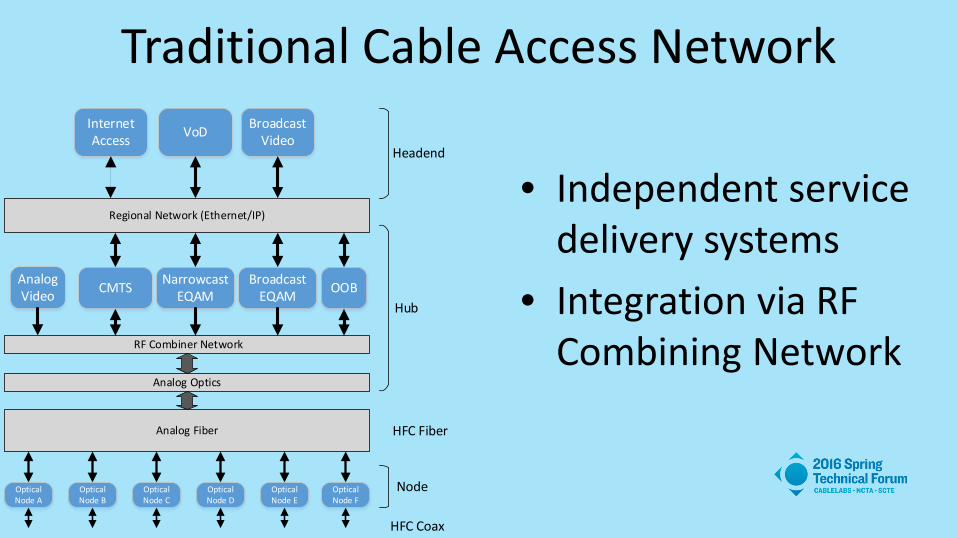
Traditional Cable Access Network
• Independent service delivery systems
• Integration via RF Combining Network
Broadcast Video
Regional Network (Ethernet/IP)
CMTS NarrowcastEQAM OOB
RF Combiner Network
Analog Optics
Analog Fiber
Optical Node A
Optical Node B
Optical Node C
Optical Node D
Optical Node F
Optical Node E
VoDInternet Access
Hub
Node
HFC Fiber
HFC Coax
Headend
Analog Video
BroadcastEQAM

Cable Access Network with CCAP
Cable Convergence:
Integration of DOCSIS and MPEG video services into a single delivery platform with combined RF output at very large scale.
Broadcast Video
Regional Network (Ethernet/IP)
I-CCAP: CMTS+EQAM OOB
RF Combiner Network
Analog Optics
Analog Fiber
Optical Node A
Optical Node B
Optical Node C
Optical Node D
Optical Node F
Optical Node E
VoDInternet Access
Hub
Node
HFC Fiber
HFC Coax
Headend
Analog Video

Converged Yet Mostly Separate
• Above the PHY layer, MPEG Video and DOCSIS subsystems of CCAP are mostly divergent.
• Modularity based on RF line card results in fixed scaling of MAC-level and PHY-level resources.
• Reduced availability due to reliance on hardware components shared between services.
MPEG MACSubsystem
I-CCAP RF Line Card
DOCSIS MACSubsystem
PIC
Switch Fabric
Interface
DS RF Port
US RF Port
DS PHY
US PHY
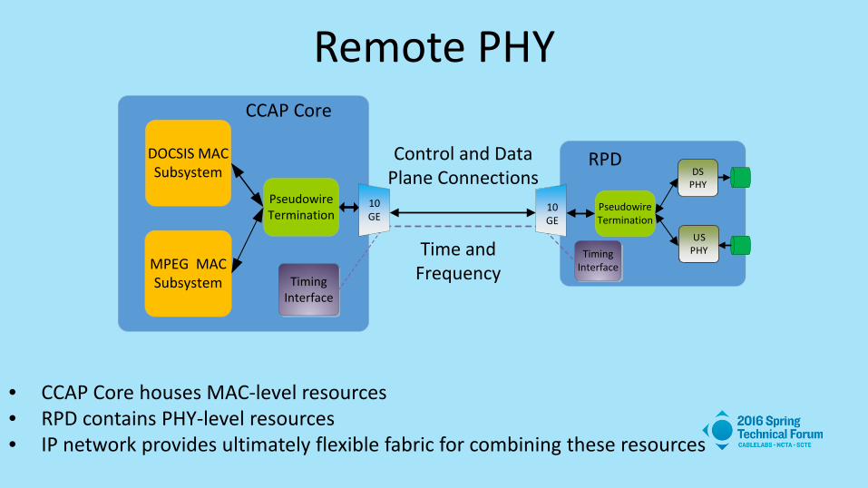
Remote PHY
• CCAP Core houses MAC-level resources • RPD contains PHY-level resources • IP network provides ultimately flexible fabric for combining these resources
MPEG MACSubsystem
CCAP Core
DOCSIS MACSubsystem
Pseudowire Termination
TimingInterface
Control and Data Plane Connections
Time and Frequency
10 GE
DS PHY
US PHY
Pseudowire Termination
TimingInterface
RPD
10 GE
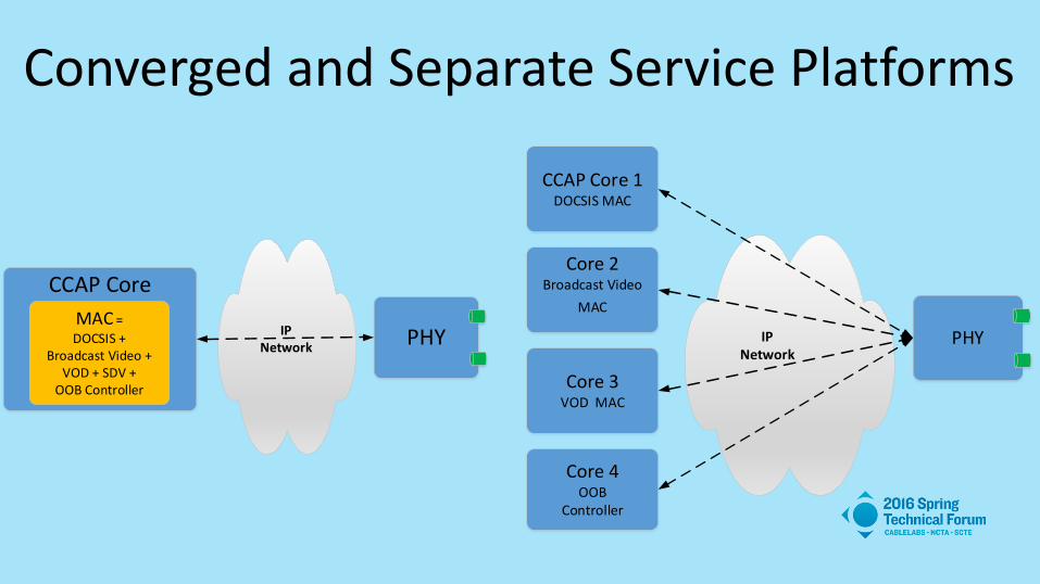
Converged and Separate Service Platforms
CCAP Core
PHYIPNetwork
MAC =DOCSIS +
Broadcast Video +VOD + SDV +
OOB Controller
CCAP Core 1DOCSIS MAC
Core 2Broadcast Video
MAC
Core 4OOB
Controller
PHY
Core 3VOD MAC
IPNetwork

Virtual Splitting and Combining
• Cost effective broadcast service delivery. • Independent scaling of MAC and PHY resources. • Fundamental tools in building serving groups spanning multiple RPDs.
CCAP CoreMAC
IPNetwork
PHY
PHY
PHY
PHY
PHY
Network replicates data sent from a single MAC-level channel to PHY-level channels in
multiple RPDs
Multicast Pseudowire CCAP CoreMAC
IPNetwork
PHY
PHY
PHY
PHY
PHY
Phy-level channels from multiple PHYs are mapped to one MAC-level channel
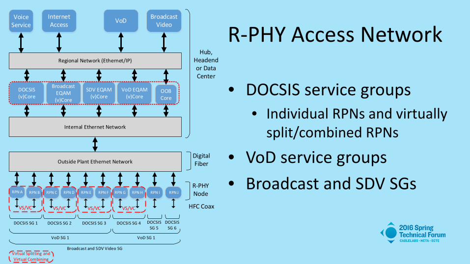
R-PHY Access Network
• DOCSIS service groups • Individual RPNs and virtually
split/combined RPNs
• VoD service groups • Broadcast and SDV SGs
Broadcast Video
Regional Network (Ethernet/IP)
DOCSIS (v)Core
OOB Core
Outside Plant Ethernet Network
RPN A
VoDInternet Access
Hub, Headend or Data Center
R-PHYNode
HFC Coax
VoiceService
Internal Ethernet Network
Digital Fiber
RPN B RPN C RPN D RPN E RPN F RPN G RPN H RPN I RPN J
Broadcast EQAM (v)Core
VoD EQAM (v)Core
DOCSIS SG 1 DOCSIS SG 2 DOCSIS SG 3 DOCSIS SG 4 DOCSIS SG 6
VoD SG 1 VoD SG 1
Broadcast and SDV Video SG
DOCSIS SG 5
VS/VC VS/VC VS/VC VS/VC
SDV EQAM (v)Core
Virtual Splitting and Virtual Combining

Conclusion • The unmatched flexibility of Remote
PHY technology with features such as virtual splitting and combining redefines the traditional meaning of cable service convergence.
• R-PHY enables cable operators to
build access networks which exceed the original convergence and scaling goals for CCAP.