Mobile Surface Measurement - MSI-Viking Surface Measurement. 13 ... allows users to merge roughness,...
16
12 Mobile Surface Measurement
Transcript of Mobile Surface Measurement - MSI-Viking Surface Measurement. 13 ... allows users to merge roughness,...

12
Mobile Surface Measurement

13
SURFCOM 130HANDYSURF SURFCOM FLEX
14
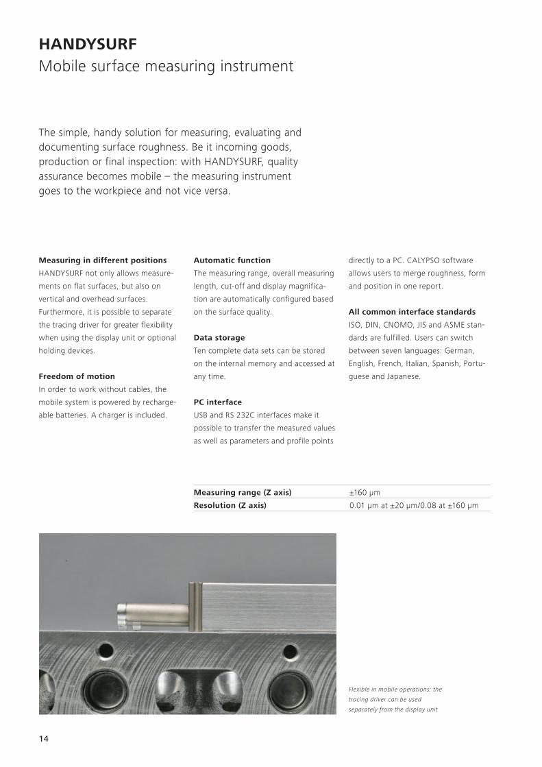
The simple, handy solution for measuring, evaluating and documenting surface roughness. Be it incoming goods, production or final inspection: with HANDYSURF, quality assurance becomes mobile – the measuring instrument goes to the workpiece and not vice versa.
Measuring in different positions
HANDYSURF not only allows measure-
ments on flat surfaces, but also on
vertical and overhead surfaces.
Furthermore, it is possible to separate
the tracing driver for greater flexibility
when using the display unit or optional
holding devices.
Freedom of motion
In order to work without cables, the
mobile system is powered by recharge-
able batteries. A charger is included.
directly to a PC. CALYPSO software
allows users to merge roughness, form
and position in one report.
All common interface standards
ISO, DIN, CNOMO, JIS and ASME stan-
dards are fulfilled. Users can switch
between seven languages: German,
English, French, Italian, Spanish, Portu-
guese and Japanese.
HANDYSURFMobile surface measuring instrument
Automatic function
The measuring range, overall measuring
length, cut-off and display magnifica-
tion are automatically configured based
on the surface quality.
Data storage
Ten complete data sets can be stored
on the internal memory and accessed at
any time.
PC interface
USB and RS 232C interfaces make it
possible to transfer the measured values
as well as parameters and profile points
Flexible in mobile operations: the
tracing driver can be used
separately from the display unit
Measuring range (Z axis) ±160 µm
Resolution (Z axis) 0.01 μm at ±20 μm/0.08 at ±160 μm
15
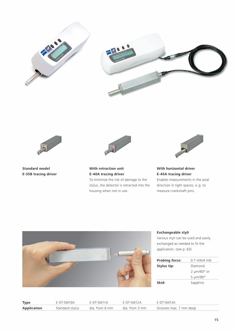
Exchangeable styli
Various styli can be used and easily
exchanged as needed to fit the
application. (see p. 63)
Probing force: 0.7 mN/4 mN
Stylus tip: Diamond
2 μm/60° or
5 μm/90°
Skid: Sapphire
Standard model
E-35B tracing driver
With retraction unit
E-40A tracing driver
To minimize the risk of damage to the
stylus, the detector is retracted into the
housing when not in use.
With horizontal driver
E-45A tracing driver
Enables measurements in the axial
direction in tight spaces, e. g. to
measure crankshaft pins.
Type E-DT-SM10A E-DT-SM11A E-DT-SM12A E-DT-SM13A
Application Standard stylus dia. from 6 mm dia. from 3 mm Grooves max. 7 mm deep

16
HANDYSURFAccessories
Magnetic column with ball joints
Flexible magnetic columns with two ball
joints and one swivel joint
High-speed thermal printer
with high resolution
E-WJ-S88A surface attachment
Attachment for manual measurement
of flat surfaces
E-WJ-S85A shaft attachment
Attachment for manual measurement
of shafts and cylinders
E-WJ-S86A orthogonal attachment
Alignment aid for reliable alignment at
right angles to the bearing surface
DT57506 extension
Extension of the sensing arm by 50 mm,
e. g. for measuring deep boreholes
DT57707 extension adapter
The 90° offset extension enables
lateral probing
SURFCOM FLEX
Compact control and analysis unit
with integrated printer and Excel-based
evaluation software
Column with granite base
Stable column with massive granite
base plate (see also image to the right)
18
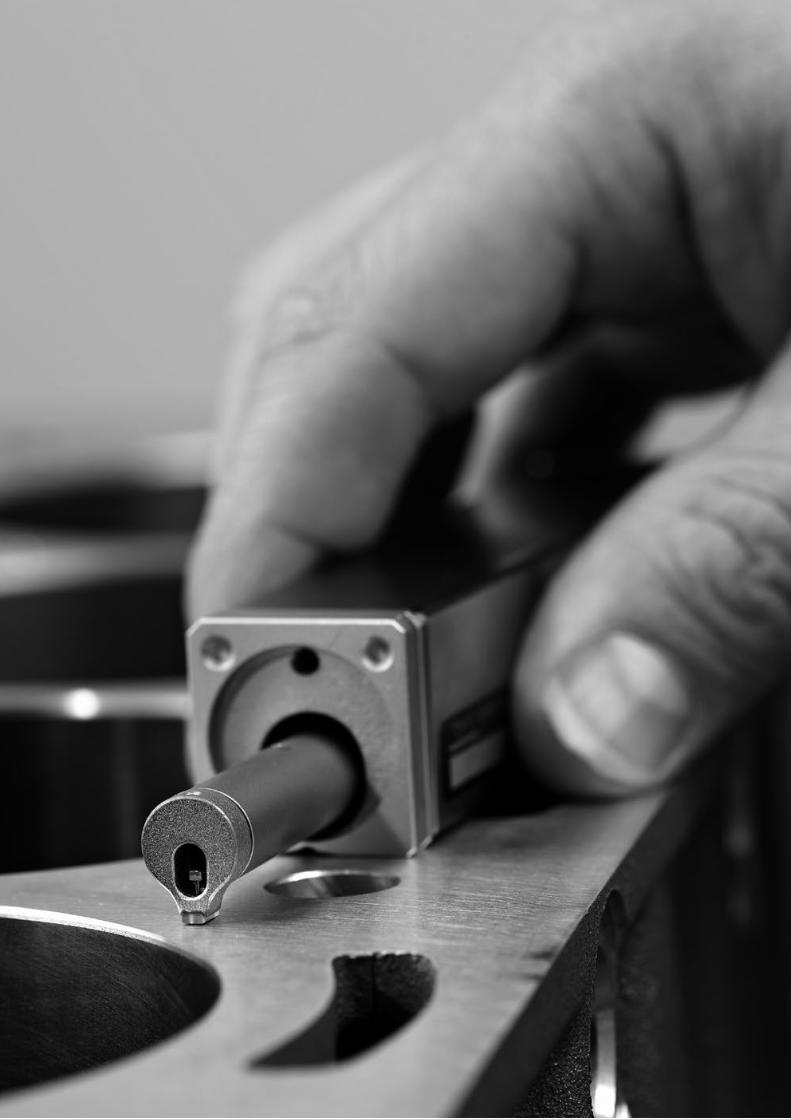
The SURFCOM 130 is designed for mobile use in production. The separate control and analysis unit features a touchscreen display and a printer. An interface enables external data storage and professional analysis with ACCTee PRO on a computer.
SURFCOM 130Mobile surface measuring instrument
Compact tracing driver
• Highly accurate free stylus-and-arm
system
• 50 mm traversing length for
measuring waviness
• Large deflection range of up to 1.6
mm for measuring roughness on radii
• Easy to exchange the sensing arm
International analysis parameters
Select the required standard: ISO,
CNOMO; ASME, JIS
Touchscreen control unit
with integrated printer
The user-friendly touchscreen display
is available in color. Thanks to the
integrated printer, reports, graphics
and notes can be printed easily.
Virtual notepad
The touch pen allows you to record
notes and drawings on the display.
Configurable user interface
Create a customized menu that only
contains the functions you use most.
Straightness accuracy 0.3 µm/50 mm
Traversing length 50 mm
19
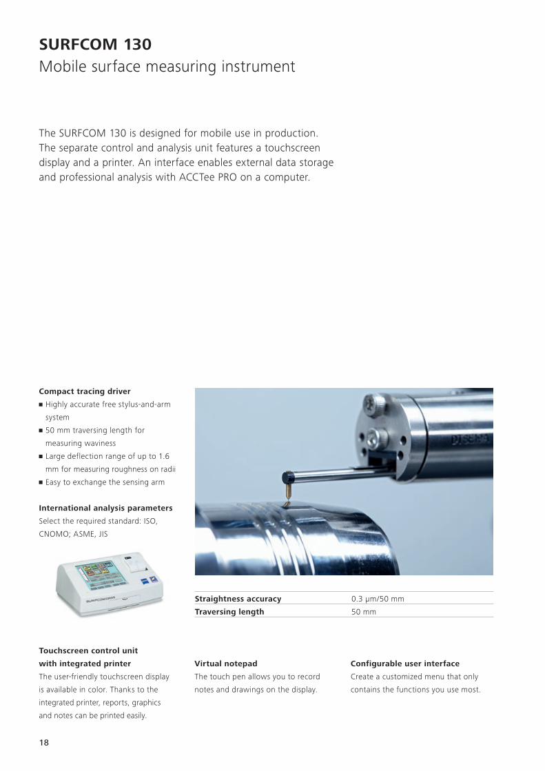
User guidance
Helps measuring technicians configure
all measuring conditions.
Automatic function
The measuring range, overall measuring
length, cut-off and display magnification
are automatically configured based on
the surface quality.
Extensive analysis functions
• Evaluate all roughness values as per
the standards: Ra, Rz, Rt, Rsm, etc.
• All waviness parameters
• Various filters, profile types and
characteristics
Tilt correction
Six tilt correction methods for profile
analysis: line, curve (ARC), first half,
second half, beginning / end, spline.
User-defined main menuProfile display and parameter results
Special evaluations
Each parameter can be recalculated for
selected profile areas. The corresponding
area is easily configured via the cursor
in the profile.
Memory card slot
A PCMCIA slot for saving and managing
profiles, results, measuring programs
and special programs.
PC interface
RS-232C for professional evaluation
with ACCTee PRO roughness software
Language selection
German, English, French, Spanish,
Portuguese and Japanese

20
SURFCOM 130 Accessories
Roll foot, flat
E-MA-S62A
Attachment for easy positioning
on shafts. For measurable exterior
diameters of 60 mm and more
Perpendicular stylus mount
E-DH-S17A
For lateral tracing in the feed direction
Battery set
E-MA-S65A
AC adapter, battery, charger
PCMCIA memory cards up to 1 GB
E-MU-S50C
Memory card for up to 7000 measuring
conditions and measurement data
Roll foot, raised
E-MA-S63A
Raised attachment for easy positioning
on shafts. For measurable exterior
diameters of 60 mm and more
Universal stylus mount
E-DH-S107A
Stylus mount for measurements
on non-flat surfaces
Z = – 50 mm

dia. 2.7dia. 1.2dia. 1.2
0.8
dia. 2.7
1.7
dia. 1.2
0.7
dia. 1.2
1.7
0.7dia. 15
dia. 1.2dia. 2.7
21
Measuring columns
Measuring columns for quickly and
accurately adjusting the height and tilt
of the tracing driver
Base plate (granite): 400 x 240 x 50 mm
Max. height (Z): 300 mm
SURFCOM FLEX
Compact control and analysis unit
(see p. 22)
Cat. no. 1059-167 1079-358 1079-356
Length of sensing arm 22 mm 22 mm 15 mm
For boreholes larger than dia. 7.5 mm - dia. 2 mm
For groove depths <4 mm <15 mm -
Measuring range ± 400 µm ± 400 µm ± 400 µm
Stylus tip 2 µm/60°, diamond 2 µm/60°, diamond 2 µm/60°, diamond
Cat. no. 1084-495 1128-388 1054-833
Length of sensing arm 62 mm 15 mm 62 mm
For boreholes larger than dia. 2 mm - -
For groove depths - - <15 mm
Measuring range ± 800 µm ± 400 µm ± 800 µm
Stylus tip 2 µm/60°, diamond 2 µm/60°, diamond 2 µm/60°, diamond
Sensing arms
Excerpt from our stylus catalog

Serial No. Comment Measuring date 15.12.2015WorkPiece name Inspector Measuring time 12:55:23
Measuring conditionMeasurement type Roughness Cutoff 0.8mm λs filter 300
Caluculation standards JIS'01/ISO'97/DIN Type of filter Gaussian Unit mm/umEvaluation length 4.00mm Measuring range 800.0umMeasuring speed 0.3mm/s Form remove Straight
Measuring ResultsRa 0.265umRz 2.419um
2.700
1.800
0.900
0.000
0.900
1.800
2.700
0 0.4 0.8 1.2 1.6 2 2.4 2.8 3.2 3.6 4
2.700
1.800
0.900
0.000
0.900
1.800
2.700
0 0.4 0.8 1.2 1.6 2 2.4 2.8 3.2 3.6 4
22
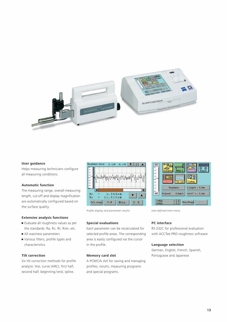
The SURFCOM FLEX is an easy-to-use control and evaluation unit with an integrated printer. It can be used in combination with the HANDYSURF and SURFCOM 130 tracing drivers. Thanks to its ease of use and robustness, the SURFCOM FLEX is at home in the workshop.
SURFCOM FLEXMobile control and evaluation unit
Small, lightweight and flexible
Thanks to its compact size and robust
design, the SURFCOM FLEX controller
can be easily transported and used any-
where. The small device also houses a
printer. The 8.9 cm color display is very
easy to read. Measuring results can be
displayed numerically and graphically.
They can also be printed using the
report printer.
The SURFCOM FLEX can also be operated
using a battery. A power supply unit is
also included.
SURFCOM FLEX 35/40
For surface measurements on all flat
surfaces – even vertically and overhead.
SURFCOM FLEX 45
For surface measurements in the axial
direction in tight spaces, e.g. to measure
crankshaft pins.
SURFCOM FLEX 50
Surface measurements with the
SURFCOM 130 tracing driver. To
capture roughness, profile and
waviness parameters.
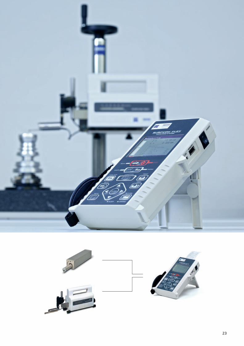
System combination
Memory and interfaces
Measuring conditions and results can
be stored on the internal memory or
on the enclosed 8 GB memory card
(standard USB). A mini USB interface
enables data evaluation on a computer.
Excel-based evaluation software is
included.
Options
• Holder for the E-35 or E-40 tracing
driver
• Data transmission to CALYPSO
coordinate measuring machine
software for roughness, size, form
and position in one report
The SURFCOM FLEX with optional
clamping device for the E-35B or E-40B
tracing driver
SURFCOM FLEX report
23

62
Technical DataHANDYSURF
HANDYSURF E35B/40A HANDYSURF E45A
Tracing driver
Traversing length 12.5 mm 4 mm
Measuring speed 0.6 mm/s
Retraction speed 1 mm/s
Variable measured length 0.4 to 12.5 mm in 0.1 mm increments
Graduated measured length 5 λc (0.4/1.25/4/12.5 mm) λc (0.08/0.25/0.8 mm)
Probing system
Measuring range ± 160 μm
Resolution 0.01 µm at ±20 µm/0.08 at ±160 µm
Measuring force 4 mN
Stylus tip material Diamond
Stylus tip radius 5 μm (optional 2 μm, measuring force 0.7 mN)
Skid Sapphire, radius 32 mm
Data processing
Data storage 10 data sets, profile curves, parameters, measuring conditions
Filter type Gaussian DIN 4777 and 2RC
Critical wavelength λc 0.08/0.25/0.8/2.5 mm
Standard ISO/DIN/JIS/CNOMO/ASME
Roughness parameters Ra, Rz, RSm, Rq, Rp, Rt, R3z, Pc, Pt, Rmr, PK, Rpk, Rvk, Mr1, Mr2, Vo, K, Rzmax
Display unit
Output values LCD, 16 characters x 2 lines
Units Measuring conditions, parameters and tolerance comparison
Data interface PC interface
Languages German, English, French, Italian, Spanish, Portuguese and Japanese
Miscellaneous
Power supply Integrated rechargeable battery with charger 100, 120, 127, 220, 240 V, 50–60 Hz
Power consumption Approx. 0.5 VA (battery suitable for approx. 7 hours continuous operation)
Dimensions, weight Width = 186 mm, length = 68 mm, height = 54 mm, weight = 0.6 kg
Standard accessories Calibration and stylus feature for tracing driver, stand for tracing driver, extension cable and transport box
Printer (optional)
Name Compact printer
Printing method Thermal
Recording curves Section profile curve, roughness curve, capacity curve, roughness motif curve, waviness motif curve,
waviness trend curve
Recording magnification V 100, 200, 500, 1 K, 2 K, 5 K, 10 K, Auto
Recording magnification H 1, 2, 5, 10, 20, 50, 100, 200, Auto
Accessories Printer paper, connection cable
68.612.6
1.5 1.5
68.314.5 41.2 12.6
dia.
9.5
4.5
dia.
9.5
12.3
2.9
2.7 1.5
12.612.6
41.214.568.3
dia.
9.5
dia.
9.5
2.7
7.2
2.8 1.5
68.6
63
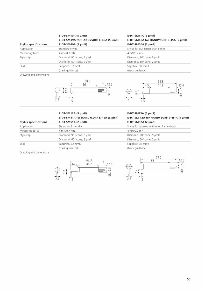
E-DT-SM10A (5 µmR) E-DT-SM11A (5 µmR)
E-DT-SM39A for HANDYSURF E-45A (5 µmR) E-DT-SM40A for HANDYSURF E-45A (5 µmR)
Stylus specifications E-DT-SM49A (2 µmR) E-DT-SM50A (2 µmR)
Application Standard stylus Stylus for dia. larger than 6 mm
Measuring force 4 mN/0.7 mN 4 mN/0.7 mN
Stylus tip Diamond, 90° cone, 5 µmR
Diamond, 60° cone, 2 µmR
Diamond, 90° cone, 5 µmR
Diamond, 60° cone, 2 µmR
Skid Sapphire, 32 mmR
(track guidance)
Sapphire, 32 mmR
(track guidance)
Drawing and dimensions
E-DT-SM12A (5 µmR) E-DT-SM13A (5 µmR)
E-DT-SM41A for HANDYSURF E-45A (5 µmR) E-DT-SM 42A for HANDYSURF E-45-A (5 µmR)
Stylus specifications E-DT-SM51A (2 µmR) E-DT-SM52A (2 µmR)
Application Stylus for 3 mm dia. Stylus for grooves with max. 7 mm depth
Measuring force 4 mN/0.7 mN 4 mN/0.7 mN
Stylus tip Diamond, 90° cone, 5 µmR
Diamond, 60° cone, 2 µmR
Diamond, 90° cone, 5 µmR
Diamond, 60° cone, 2 µmR
Skid Sapphire, 32 mmR
(track guidance)
Sapphire, 32 mmR
(track guidance)
Drawing and dimensions

64
Technical DataSURFCOM 130
SURFCOM 130
Tracing driver
Traversing length 50 mm
Straightness accuracy 0.3 μm/50 mm (bandwidth)
Measuring speed 0.3/0.6/1.5/3.0 mm/s
Retraction speed 0.15-3.0 mm/s
Adjustment range in probing direction 50 mm manual
Leveling range ±1.5°
Measured distance Max. 48 mm in 0.1 mm increments
Number of single measured distances 1 to 150 (selectable)
Number of measured points max. 32,767
Probing system
Measuring range 8, 80, 800 μm (standard)
Resolution 1/64,000 of measuring range
Measuring principle Differential transformer
Measuring force 0.75 mN with interchangeable stylus (optional 4 mN)
Stylus tip radius 2 μm (optional 5, 10, 250, 800 μm R)
Data processing
Profile display R, P, W, Wc, Wec and DIN 4776
Filter type Gauss, 2RC (phase-corrected and not phase-corrected)
Critical wavelength λc of the roughness filter 0.08/0.25/0.8/2.5/8 mm
Critical wavelength ripple λf 0.08/0.25/0.8/2.5/8 mm
Magnification Horizontal 1; 2; 5; 10; 20; 50; 100; 200; 500; 1,000; 2,000; 5,000, automatic
Vertical 50; 100; 200; 500; 1,000; 2,000; 5,000; 10,000; 20,000; 50,000; 100,000 automatic
Tilt correction methods Compensating line (first half, second half, beginning/end), compensating curve, spline
Roughness parameters Ra, Rq, Rp, Rv, Rc, R3z, RzISO, Rt, RmaxDIN, Pc, S, RΔa, RΔq, Rλa, Rλq, Ir, RsK, Rku, tp, tp2,
Rmr, R c, Rk, Rpk, Rvk, Mr1, Mr2, Vo, K, CNOMO parameters, JIS-2001, JIS-1994, JIS-1982,
ISO-1997, DIN-1990, ASME-1995 …
Profile parameters Pt, TILT A, step height, AVH, Hmax, Hmin, AREA …
Waviness parameters Wt, Wa, WSm, Wsk, Wku, Wmr, Wdc …
Average of parameters Up to 100 bits of data possible
Tolerance comparison Possible
Profile analysis Actual profile, Abbott curve, amplitude density, Fourier analysis
Measurement of interrupted surfaces Possible
Units μm, μinch (selectable)
Display unit 16.5 cm color graphic LCD, touchscreen
Data output 60 mm thermal printer
Print width 50 mm
Data interface RS-232C
IC memory card (option) 128 MB memory card for up to 7000 measuring conditions and measurement data
Miscellaneous
Power supply 100, 110, 120, 127, 220, 240 V (± 10%, 50/60 Hz) optional: battery powered
Power consumption 30 VA
Dimensions, weight Width = 700 mm, depth = 300 mm, height = 150 mm, weight = 8 kg
Standard accessories Calibration and stylus test standards, tool
65
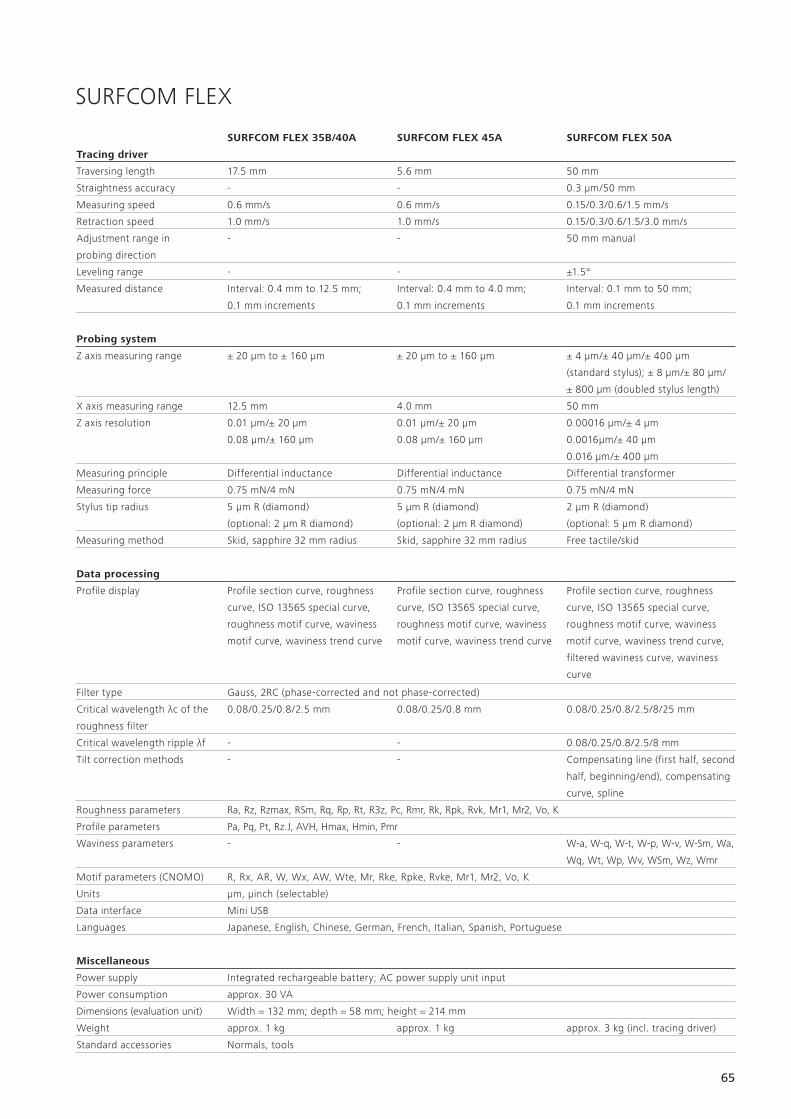
SURFCOM FLEX
SURFCOM FLEX 35B/40A SURFCOM FLEX 45A SURFCOM FLEX 50A
Tracing driver
Traversing length 17.5 mm 5.6 mm 50 mm
Straightness accuracy - - 0.3 µm/50 mm
Measuring speed 0.6 mm/s 0.6 mm/s 0.15/0.3/0.6/1.5 mm/s
Retraction speed 1.0 mm/s 1.0 mm/s 0.15/0.3/0.6/1.5/3.0 mm/s
Adjustment range in
probing direction
- - 50 mm manual
Leveling range - - ±1.5°
Measured distance Interval: 0.4 mm to 12.5 mm;
0.1 mm increments
Interval: 0.4 mm to 4.0 mm;
0.1 mm increments
Interval: 0.1 mm to 50 mm;
0.1 mm increments
Probing system
Z axis measuring range ± 20 µm to ± 160 µm ± 20 µm to ± 160 µm ± 4 µm/± 40 µm/± 400 µm
(standard stylus); ± 8 µm/± 80 µm/
± 800 µm (doubled stylus length)
X axis measuring range 12.5 mm 4.0 mm 50 mm
Z axis resolution 0.01 µm/± 20 µm
0.08 µm/± 160 µm
0.01 µm/± 20 µm
0.08 µm/± 160 µm
0.00016 µm/± 4 µm
0.0016µm/± 40 µm
0.016 µm/± 400 µm
Measuring principle Differential inductance Differential inductance Differential transformer
Measuring force 0.75 mN/4 mN 0.75 mN/4 mN 0.75 mN/4 mN
Stylus tip radius 5 µm R (diamond)
(optional: 2 µm R diamond)
5 µm R (diamond)
(optional: 2 µm R diamond)
2 µm R (diamond)
(optional: 5 µm R diamond)
Measuring method Skid, sapphire 32 mm radius Skid, sapphire 32 mm radius Free tactile/skid
Data processing
Profile display Profile section curve, roughness
curve, ISO 13565 special curve,
roughness motif curve, waviness
motif curve, waviness trend curve
Profile section curve, roughness
curve, ISO 13565 special curve,
roughness motif curve, waviness
motif curve, waviness trend curve
Profile section curve, roughness
curve, ISO 13565 special curve,
roughness motif curve, waviness
motif curve, waviness trend curve,
filtered waviness curve, waviness
curve
Filter type Gauss, 2RC (phase-corrected and not phase-corrected)
Critical wavelength λc of the
roughness filter
0.08/0.25/0.8/2.5 mm 0.08/0.25/0.8 mm 0.08/0.25/0.8/2.5/8/25 mm
Critical wavelength ripple λf - - 0.08/0.25/0.8/2.5/8 mm
Tilt correction methods - - Compensating line (first half, second
half, beginning/end), compensating
curve, spline
Roughness parameters Ra, Rz, Rzmax, RSm, Rq, Rp, Rt, R3z, Pc, Rmr, Rk, Rpk, Rvk, Mr1, Mr2, Vo, K
Profile parameters Pa, Pq, Pt, Rz.J, AVH, Hmax, Hmin, Pmr
Waviness parameters - - W-a, W-q, W-t, W-p, W-v, W-Sm, Wa,
Wq, Wt, Wp, Wv, WSm, Wz, Wmr
Motif parameters (CNOMO) R, Rx, AR, W, Wx, AW, Wte, Mr, Rke, Rpke, Rvke, Mr1, Mr2, Vo, K
Units μm, μinch (selectable)
Data interface Mini USB
Languages Japanese, English, Chinese, German, French, Italian, Spanish, Portuguese
Miscellaneous
Power supply Integrated rechargeable battery; AC power supply unit input
Power consumption approx. 30 VA
Dimensions (evaluation unit) Width = 132 mm; depth = 58 mm; height = 214 mm
Weight approx. 1 kg approx. 1 kg approx. 3 kg (incl. tracing driver)
Standard accessories Normals, tools