IP 246 Positioning Module - Siemens for Handling Electrostatically Sensitive Devices (ESD) 1 What...
351
SIEMENS SIMATIC S5 1P 246 Positioning Module Manual Order No. 6ES5998-5SA23 Release 04
Transcript of IP 246 Positioning Module - Siemens for Handling Electrostatically Sensitive Devices (ESD) 1 What...
SIEMENS
SIMATIC S5
1P 246Positioning Module
Manual
Order No. 6ES5998-5SA23Release 04

;.;.
W. ha- chadmd tho oont.nts of this manual for ● grwmcnt tith tho Tho reproduction. transmission or usa of thk document or its con-h - m and so- dnuibad. Sinw dowaiions c a n n o t ba pr~ tents is not pwmittad without ● xpmu wdton authority.e l u d e d antiroly. w cannot OUUWIIOO full agm.mrnt. H — , tho Ofiondom w i l l b Iiabfs f o r dmrqa. M righa, incfuding righ~data in this manual am r~ rqularfy and any nwmsoary oo?mc- cmatd by patent grant or mgi-mtion of ● utilky mod.1 or duign,tions indudcd in subquont editions. Suggestions for imprownont am reswud.am w.lcem.d.
T.chnical data subjaot to change. Cc.pyright@ Si.mww G 19SS Uf Rights Ruowd
Siemens Aktiengesellschaft Order k.:ssssss-susOrdoI frun: EIddmnkwwk KAruha
Print.d m the Fadord Rapublic d &tmmy
Contents
Warnings C79000-R8576-C650InformationSuggestions/Corrections
How to Use this ManualC79000-B8576-C650 -02
Fundamentals of PositioningReference Manual C79000-B8576-C651 -02
HardwareInstructions C79000-B8576-C652 -03
FunctionsReference Manual C79000-B8576-C653 -03
Communications Software COM 246User’s Guide C79000-B8576-C654-02
Standard Function Blocks FB 164 and FB 165User’s Guide C79000-B8576-C655-02
Planning, Installation and ServiceInstallation Guide C79000-B8576-C656-02
List of Key WordsIndex C79000-B8576-C657-02
2
3
5
6
7
8
9
10
6ES5 998-5SA23, Rel. 04

Guidelines for HandlingElectrostatically Sensitive Devices (ESD)
1 What is ESD?VSLI chips (MOS technology) are used in practically all SIMATIC S5 and TELEPERM M mod-ules. These VLSI components are, by their nature, very sensitive to overvoitages and thus toelectrostatic discharge:
They are therefore defined as“Electrostatically sensitive Qevices”
“ESD” is the abbreviation used internationally.
The following warning label on the cabinets, subracks and packing indicates that electrostaticallysensitive components have been used and that the modules concerned are susceptible to touch:
/A\\,ALESDS can be destroyed by voltage and energy levels which are far below the level perceptible tohuman beings. Such voltages already occur when a component or a module is touched by aperson who has not been electrostatically discharged. Components which have been subjectedto such overvoltage cannot, in most cases, be immediately detected as faulty; the fault occursonly after a long pemxl in operation.
An electrostatic discharge- of 3500 V can be felt
of 4500 V can be heardmust take place at a minimum of 5000 V to be seen.
But just a fraction of this voltage can already damage or destroy an electronic component.
The typical data of a component can suffer due to damage, overstressing or weakening causedby electrostatic discharge; this can result in tempora~ fault behavior, e.g. in the case of
- temperature variations,mechanical shocks,vibrations,
- change of load.
Only the consequent use of protective equipment and carefu!handling such components can effectively prevent functionalmodules.
observance of the precautions fordisturbances and failures of ESD
~ Slmns AG c79000.D8076-C333 -01 1
ESD Guidelines
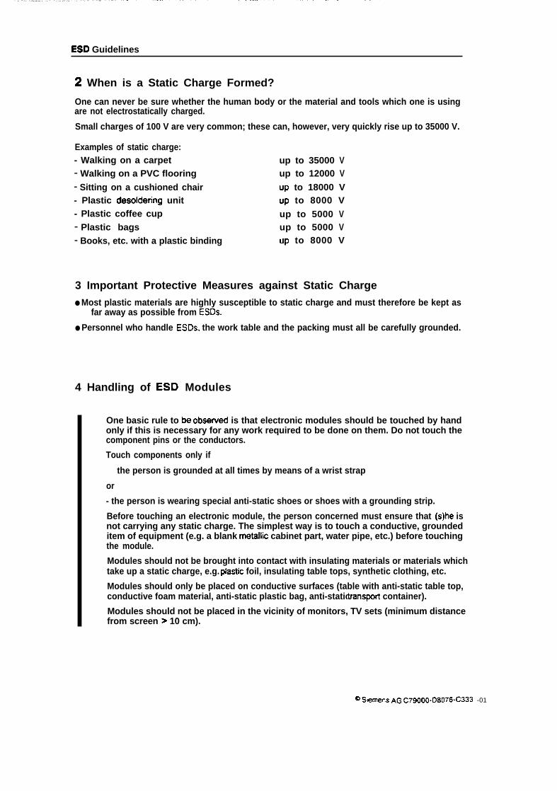
2 When is a Static Charge Formed?
One can never be sure whether the human body or the material and tools which one is usingare not electrostatically charged.
Small charges of 100 V are very common; these can, however, very quickly rise up to 35000 V.
Examples of static charge:- Walking on a carpet up to 35000 v- Walking on a PVC flooring up to 12000 v- Sitting on a cushioned chair Up to 18000 V- Plastic desoldenng unit Up to 8000 V- Plastic coffee cup up to 5000 v- Plastic bags up to 5000 v- Books, etc. with a plastic binding Up to 8000 V
3 Important Protective Measures against Static Charge
● Most plastic materials are highly susceptible to static charge and must therefore be kept asfar away as possible from ESDS.
● Personnel who handle ESDS, the work table and the packing must all be carefully grounded.
4 Handling of ESD Modules
One basic rule to be obsenmcf is that electronic modules should be touched by handonly if this is necessary for any work required to be done on them. Do not touch thecomponent pins or the conductors.
Touch components only if
the person is grounded at all times by means of a wrist strap
or
- the person is wearing special anti-static shoes or shoes with a grounding strip.
Before touching an electronic module, the person concerned must ensure that (s)he isnot carrying any static charge. The simplest way is to touch a conductive, groundeditem of equipment (e.g. a blank metaflic cabinet part, water pipe, etc.) before touchingthe module.
Modules should not be brought into contact with insulating materials or materials whichtake up a static charge, e.g. plastic foil, insulating table tops, synthetic clothing, etc.
Modules should only be placed on conductive surfaces (table with anti-static table top,conductive foam material, anti-static plastic bag, anti-static transpon container).
Modules should not be placed in the vicinity of monitors, TV sets (minimum distancefrom screen > 10 cm).
@ S,emens AG c79000-D8076-C333 -01
I
ESD Guidelines
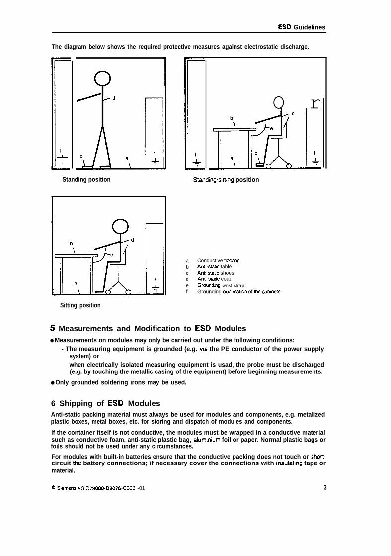
The diagram below shows the required protective measures against electrostatic discharge.
f&
.
1
/d
c
[
f+
Standing position
O r
Standinglsitting position
a Conductive flmringb Antbswc tablec AntMabc shoesd Ant@atic coate Groundng wrist strapf Grounding connecbon of the cabinets
Sitting position
5 Measurements and Modification to ESD Modules● Measurements on modules may only be carried out under the following conditions:
- The measuring equipment is grounded (e.g. via the PE conductor of the power supplysystem) orwhen electrically isolated measuring equipment is usad, the probe must be discharged(e.g. by touching the metallic casing of the equipment) before beginning measurements.
● Only grounded soldering irons may be used.
6 Shipping of ESD ModulesAnti-static packing material must always be used for modules and components, e.g. metalizedplastic boxes, metal boxes, etc. for storing and dispatch of modules and components.
If the container itself is not conductive, the modules must be wrapped in a conductive materialsuch as conductive foam, anti-static plastic bag, alummium foil or paper. Normal plastic bags orfoils should not be used under any circumstances.
For modules with built-in batteries ensure that the conductive packing does not touch or short-circuit the battery connections; if necessary cover the connections with insulating tape ormaterial.
@ s,ernens A(3 C79000-D8076-C333 -01 3
m

SIEMENSSIMATIC S5IP246 Positioning Module Incremental 6ES5246-4UA31 / -4UA41
Absolute 6ES5246-4UBII / -4UB21How to Use this Manual
Notes C79000-B8576-C650 -02
B85766W-02
Notes on How to Use this Manual
This manual describes a system for closed-loop position control of two independent drives.
The system comprises the following components:
● IP246 positioning module, absolute version (catalog name 1P 246A) orincremental version (catalog name IP2461)
● communications software COM246 (catalog name COM246R)
● standard function blocks FB164 and FB165 (catalog name FB164E and FB165E)
The IP246 positioning module represents the link between your plant and the programmablecontroller (PC). The standard function block FB164 is used for operating and monitoring, andFB165 for assigning parameters to the IP246. With the programming package COM246, you cangenerate, save and print machining programs and machine data. COM246 is also used to testthe IP246 online with the plant connected.
This manual refers to the following products:
The module IP246
● The incremental version for ventilated operation (in the S5 135, S5 150 or S5 155),order number 6ES5 246- 4UA31.
● The incremental version for non-ventilated operation (in the S5 115),order number 6ES5 246- 4UA41.
● The absolute version for ventilated operation (in the S5 135, S5 150 or S5 155),order number 6ES5 246- 4UBI 1.
● The absolute version for non-ventilated operation (in the S5 115),order number 6ES5 246- UB21.
The communications software COM246
● From issue A03.0,order number 6ES5 895- 4UB21.
The standard function blocks FB164 and FB165
● For the S5 115,order number 6ES5 845- 8TA01.
● For the S5 135 with CPU922 or 928,order number 6ES5 842- 8TB01.
● For the S5 150,order number 6ES5 844- 8TA01.
● For the S5 155,order number 6ES5 846- 8TA01.
3
SS576650-02
,.. .”.
,,,
The manual is structured to allow you to become familiar with the system and can later be usedas a reference work to look up specific points.
Part 2:
Part 2 “Fundamentals of Positioning” introduces terms you require to work withthe positioning module, e.g.:
● machine data,
● machining programs,
● axis attributes,
● messages.
By familiarizing yourself with these terms, you will also gain a better understandingof the functions and concept underlying the IP246.
Part 3:
Part 3 “Hardware” deals with the hardware requirements necessary to use theIP246 in a variety of situations. This encompasses the following:
● connections,
● jumper settings,
● switch settings.
Part 4:
Part 4 “Functions” introduces you to the operating concept of the IP246. This isbased on the following:
● operating functions,
● monitoring functions.
These functions and their effects are described.
Part 5:
Patt 5 “Communications Software COM246° explains how to assign parametersto the IP246 and how to test it using this software package. The following aspectsare covered:
● generating machine data and machining programs,
● saving the generated data,
● storing the data in the memory of the PG,
● printing machine data records and machining programs,
● testing the IP246 with the plant connected.
4
6S576650-02
Part 6:
Part 6 “Standard Function Blocks FB164 and FB165° describes the assignmentof parameters, operation and monitoring of the IP246 by the CPU. This descriptiondiscusses the following:
● FB164 for operating and monitoring the IP246,
● FBI 65 for assigning parameters to the IP246,
● the structure of the machine data and machining programs in a STEP 5 datablock,
● examples of parameter assignment for an axis.
Part 7:
Part 7 “Planning, Installation and Service” contains the following:
● notes on planning the drive and the machine data,
● guidelines for installing and starting the module,
9 an overview of troubleshooting routines,
● instructions for diagnosing problems,
Part 8:
Part 8 “Index” lists the most important terms used in the handbook.

s EMENS~ÿÀ SIMATIC S 5
IP246 Positioning Module
Fundamentals of Positioning
Incremental 6ES5246-4UA31 / -4UA41Absolute 6ES5246-4UBI 1 / -4UB21
Reference Manual C79000-B8576-G5142
6S576651-02
Contents
1 Introduction . . . . . . . . . . . . . . . . . . . . . . . . . . . . . . . . . . . . . . . . ... ... ... ... c.. .00s “ 5
2A Brief introduction tothe IP246 . . . . . . . . . . . . . . . . . . . . . . . . . . . . . . . . . . . . . . . . . . . . 6
3PositioningAxes . . . . . . . . . . . . . . . . . . . . . . . . . . . . . . . . . . . . . . . . . . .m.......o”..”” 83.1 What is Positioning?. . . . . . . . . . . . . . . . . . . . . . . . . . . . . . . . . . . . . . . . . . . . . . . . . . . ........83.2 Howdoes the lP246Position anAxis? . . . . . . . . . . . . . . . . . . . . . . . . . . . . . . . . . . . . .......133.3 Resolution oftheSpeed Setpoint . . . . . . . . . . . . . . . . . . . . . . . . . . . . . . . . . . . . . . . . . . . . . . . 16
4Machine Dataandtheir Structure . . . . . . . . . . . . . . . . . . . . . . . . . . . . . . . . . . . . . . . . . . . 184.1 AxisType (LinearorRotary Axis) . . . . . . . . . . . . . . . . . . . . . . . . . . . . . . . . . . . . . - . . ..-....194.1.1 The LinearAxis . . . . . . . . . . . . . . . . . . . . . . . . . . . . . . . . . . . . . . . . . . . . . . . . . . . . . . . . . . . . 204.1.2 The RotaryAxis . . . . . . . . . . . . . . . . . . . . . . . . . . . . . . . . . . . . . . . . . . . . . . . . . . . . . . . . . . . . 214.2 Position DecodingandTravel Resolution . . . . . . . . . . . . . . . . . . . . . . . . . . . . . . . . . . .......224.2.1 Measurement System . . . . . . . . . . . . . . . . . . . . . . . . . . . . . . . . . . . . . . . . . . . . . . . . .......224.2.2 Pulse Evaluation . . . . . . . . . . . . . . . . . . . . . . . . . . . . . . . . . . . . . . . . . . . . . . . . . . . . .......224.2.3 Resolution . . . . . . . . . . . . . . . . . . . . . . . . . . . . . . . . . . . . . . . . . . . . . . . . . . . . . . . . . . . . ....244.2.4 Decoding and Evaluation ofthe Absolute EncoderValue . . . . . . . . . . . . . . . . . . . . . . ....264.3TheTraversing Range . . . . . . . . . . . . . . . . . . . . . . . . . . . . . . . . . . . . . . . . . . . . . . . . . .......294.3.1 Restrictions forthe AbsoluteVersion . . . . . . . . . . . . . . . . . . . . . . . . . . . . . . . . . . . . .......304.3.2 Restrictions forthe Incremental Version . . . . . . . . . . . . . . . . . . . . . . . . . . . . . . . . . .......324.4 Speeds . . . . . . . . . . . . . . . . . . . . . . . . . . . . . . . . . . . . . . . . . . . . . . . . . . . . . . . . . . . . . . . . . ...324.5 Acceleration and Deceleration Rates . . . . . . . . . . . . . . . . . . . . . . . . . . . . . . . . . . . . . . . .....344.6 Controller Parameters . . . . . . . . . . . . . . . . . . . . . . . . . . . . . . . . . . . . . . . . . . . . . . . . . .......354.6.1 TheGain(kJ Factor . . . . . . . . . . . . . . . . . . . . . . . . . . . . . . . . . . . . . . . . . . . . . . . . . .......354.6.2 Maximum Following Error . . . . . . . . . . . . . . . . . . . . . . . . . . . . . . . . . . . . . . . . . . . . . .......364.6.3 Standstill Monitoring . . . . . . . . . . . . . . . . . . . . . . . . . . . . . . . . . . . . . . . . . . . . . . . . . .......384.7 Correction parameters . . . . . . . . . . . . . . . . . . . . . . . . . . . . . . . . . . . . . . . . . . . . . . . . . .......384.7.1 Backlash Compensation . . . . . . . . . . . . . . . . . . . . . . . . . . . . . . . . . . . . . . . . . . . . . . .......384.7.2 Tool Length Offset . . . . . . . . . . . . . . . . . . . . . . . . . . . . . . . . . . . . . . . . . . . . . . . . . . . .......404.7.3 Zero Point Offset . . . . . . . . . . . . . . . . . . . . . . . . . . . . . . . . . . . . . . . . . . . . . . . . . . . . . . . . . . . 414.80ther Parameters . . . . . . . . . . . . . . . . . . . . . . . . . . . . . . . . . . . . . . . . . . . . . . . . . . . . . . . . . . . . 414.8.1 The Polarityofthe Hardware Limit Switches . . . . . . . . . . . . . . . . . . . . . . . . . . . . . . .. .....434.8.2 Target lnformationfrom PCis BCD-Coded . . . . . . . . . . . . . . . . . . . . . . . . . . . . . . . . . . ....434.8.3The Reference Direction . . . . . . . . . . . . . . . . . . . . . . . . . . . . . . . . . . . . . . . . . . . . . . .......44 . .
5Machining Programsand their Structure . . . . . . . . . . . . . . . . . . . . . . . . . . . . . . . . .....455.1 General . . . . . . . . . . . . . . . . . . . . . . . . . . . . . . . . . . . . . . . . . . . . . . . . . . . . . . . . . . . . . . . . ....455.2 Program Header.. . . . . . . . . . . . . . . . . . . . . . . . . . . . . . . . . . . . . . . . . . . . . . . . . . . . . .......465.3 Program Statements . . . . . . . . . . . . . . . . . . . . . . . . . . . . . . . . . . . . . . . . . . . . . . . . . . .......475.4The N-function . . . . . . . . . . . . . . . . . . . . . . . . . . . . . . . . . . . . . . . . . . . . . . . . . . . . . . . . . . . . ..475.5The L-Function . . . . . . . . . . . . . . . . . . . . . . . . . . . . . . . . . . . . . . . . . . . . . . . . . . . . . . . .......485.6TheG-Functions . . . . . . . . . . . . . . . . . . . . . . . . . . . . . . . . . . . . . . . . . . . . . . . . . . . . . . . . . . . . .485.6.1 -GOO: RapidTraverse . . . . . . . . . . . . . . . . . . . . . . . . . . . . . . . . . . . . . . . . . . . . . . . . .......495.6.2 -G04: Dwell Time . . . . . . . . . . . . . . . . . . . . . . . . . . . . . . . . . . . . . . . . . . . . . . . . . . . . .......495.6.3 -G1O: Flying Change . . . . . . . . . . . . . . . . . . . . . . . . . . . . . . . . . . . . . . . . . . . . . . . . . .......495.6.4 Loops . . . . . . . . . . . . . . . . . . . . . . . . . . . . . . . . . . . . . . . . . . . . . . . . . . . . . . . . . . . . . .......515.6.5 Direction ofApproachto the Target Pointwitha Rotary Axis . . . . . . . . . . . . . . . . . .......525.6.6 Tool Length Offset . . . . . . . . . . . . . . . . . . . . . . . . . . . . . . . . . . . . . . . . . . . . . . . . . . . .......535.6.7 Zero Point0ffset . . . . . . . . . . . . . . . . . . . . . . . . . . . . . . . . . . . . . . . . . . . . . . . . . . . . .......565.6.8 Dimensional Units in Machining Programs . . . . . . . . . . . . . . . . . . . . . . . . . . . . . . . . .. ....595.6.9 -G74: Reference/Home PointApproach . . . . . . . . . . . . . . . . . . . . . . . . . . . . . . . . . .......595.6.10Absoluteand Relatiie Dimensions . . . . . . . . . . . . . . . . . . . . . . . . . . . . . . . . . . . . . .......60
.,+
68576651-02
5.7 The X-Function . . . . . . . . . . . . . . . . . . . . . . . . . . . . . . . . . . . . . . . . . . . . . . . . . . . . . . . . . . . . ..605.8The F-Function . . . . . . . . . . . . . . . . . . . . . . . . . . . . . . . . . . . . . . . . . . . . . . . . . . . . . . . . . . . . ..605.9The M-Function . . . . . . . . . . . . . . . . . . . . . . . . . . . . . . . . . . . . . . . . . . . . . . . . . . . ., . .......615.10 Programming Restrictions and Syntax Diagram . . . . . . . . . . . . . . . . . . . . . . . . . . . . . . . . . . 63
6Axis Attributes . . . . . . . . . . . . . . . . . . . . . . . . . . . . . . . . . . . . . . . . . . . . . . . . . . . . . . . . . . 656.1 Machine Data Missing . . . . . . . . . . . . . . . . . . . . . . . . . . . . . . . . . . . . . . . . . . . . . . . . . .......656.2 Measurement System . . . . . . . . . . . . . . . . . . . . . . . . . . . . . . . . . . . . . . . . . . . . . . . . . .......666.3 Reference/Home Point Missing . . . . . . . . . . . . . . . . . . . . . . . . . . . . . . . . . . . . . . . . . . .......666.4Teach-in On . . . . . . . . . . . . . . . . . . . . . . . . . . . . . . . . . . . . . . . . . . . . . . . . . . . . . . . . . . . . ....666.5 Closed-Loop Position ControllerOn . . . . . . . . . . . . . . . . . . . . . . . . . . . . . . . . . . . . . . .......666.6 Axis Status’’FinishedH or”Running” . . . . . . . . . . . . . . . . . . . . . . . . . . . . . . . . . . . . . . . .......666.7 ’’Position Reached” Message . . . . . . . . . . . . . . . . . . . . . . . . . . . . . . . . . . . . . . . . . . . . .......67
7Digital lnputs/Outputsand their Effects . . . . . . . . . . . . . . . . . . . . . . . . . . . . . . . .......697.1 TheOperational Signal FUM . . . . . . . . . . . . . . . . . . . . . . . . . . . . . . . . . . . . . . . . . . . . .......697.2The’’Position Reached’’ Message . . . . . . . . . . . . . . . . . . . . . . . . . . . . . . . . . . . . . . . . .......707.3 The Digital lnputsforHardware Limit Switches . . . . . . . . . . . . . . . . . . . . . . . . . . . . . . . . . . . . 707.4 External Start/Stop . . . . . . . . . . . . . . . . . . . . . . . . . . . . . . . . . . . . . . . . . . . . . . . . . . . . . . . . . . . 71
3

BS576651-02
1 Introduction
This part introduces you to the IP246. It provides you with certain information about positioningand briefly describes the function of the IP246 positioning module and its firmware, which repre-sents the heart of the module.The following terms, which must be familiar when working with the IP246, are then explained:
machine data,
machining programs and
axis attributes.
Finally, this part provides you with information about the digital inputs and digital outputs madeavailable by the IP246 and an explanation of the limit switch concept and its effects with theIP246,
5

BS576651-02
2 A Brief Introduction to the IP246
Using the positioning module IP246, you can move and position two independent axes. Fromthe positioning jobs, the machine data and the signals from the position encoders, the modulecontinuously calculates a speed setpoint, so that the axis reaches the required target at the se-lected speed without exceeding the technical specifications of the drive.
I
Internal S5 bus I
PCentralproc. unit
I>
m \ \lnter- <face ) n ~fl
IP246 — —❑ 0 — ❑— — ——DO
M: Motor
T : Tacho.generator
n: Position measuring system
Fig. 2-1: The IP246 in the SIMATIC S5 system
Due to its adaptability, the module must have parameters assigned to it. Parameter assignmentis simple and is performed at the monitor of a programmer (PG) using the software packageCOM246. The IP246 can be assigned parameters via the PC interface, however, without the user--friendly support of the COM246 software package.
In the test mode, the COM246 software package allows you to test all the functions of the IP246and therefore the positioning functions of your plant.
Two standard function blocks FB164 and FB165 are used to incorporate the functions of theIP246 in a user program, allowing all the functions of the IP246 to be executed from the CPU.These are stored in an EPROM cartridge in the CPU. The data handling blocks for communica-tions processors are subordinate to the function blocks.
The module can be operated both from a PG and from a PC, however, the functions of the inter-faces differ from each other. Using the software package COM246, the PG is used for user-friend-ly parameter assignment, starting up and testing the module. The PC interface is used toexecute the functions of the IP246 during normal plant operation.
6
BS576651-02
Jobs can be sent to the IP246 via the PG interface and via the PC interface simultaneously.
When requested, the IP246 sends status messages via both interfaces.
Positioning module
1P 246FCjob
Jobs list
> JobPc + processing
Status messages
7mjob
Pc$ I
PGinterface interface
Fig. 2-2: Communication with the PC and PG
Each positioning operation of the IP246 is based on a machine data record specific to the axis,which must be transferred to the memory of the IP246 via one of the two interfaces. An axis isonly functional when a correct machine data record exists on the module. By making entries inthis data record, you stipulate the electrical and mechanical limits of your plant. These includethe maximum acceleration of the axis, the maximum speed, the pulse evaluation, whether youare operating a linear or rotary axis and the permitted traversing range of your axis.
With the IP246, positioning jobs can be issued in two ways, as follows:
● machining programs, i.e. a connected series of traversing jobs, dwell times, correc-tions and changes, which are stored in the memory of the IP246,
● single jobs, sent to the IP246 via an interface.
The input and deleting of a machining program is possible both via the PG and the PC interface.
It is possible to take into account differing tool lengths and to execute zero point offsets. In addi-tion, a slight drift resulting from an incorrectly adjusted power unit, can be compensated.
6S576651-02
3 Positioning Axes
3.1 What is Positioning?
Positioning means approaching a previously specified point or previously specified coordinateautomatically following a procedure established by parameter assignment. Such an operationcan be controlled by either closed-loop or open-loop control systems.
Positioning
/ \
Open- loop control Closed-loop control
Fig. 3.1 -1: Types of positioning
When using closed-loop control, the physical value to be controlled is measured and comparedand matched to another value. For the positioning module IP246, the value to be controlled isthe position of the axis.
Once parameters can be assigned for the positioning operation, a setpoint generator is necessa-ry, regardless of whether closed-loop or open-loop control is to be used. This setpoint generatorsupplies an output value, which depends both on the difference between the current position ofthe axis and the required target point, as well as on the parameters, e.g. speed, acceleration ordeceleration. The more opportunities for parameter assignment and for modifying parametersduring the positioning operation provided by the setpoint generator, the more complex and com-prehensive is its structure. In the simplest version, the output value of the setpoint generator isswitched on and off. Specifying the maximum speed and maximum acceleration and decelera-tion according to the mechanical capabilities of the plant improves the efficiency of the opera-tion. If various speeds can be preset and if the speed can be changed during the positioningoperation, the whole operation can be better matched to the particular plant or to the particulartask.
,..,,$
8
B6576651-02
‘A ‘emnsd”cerJ
I1
➤ s’tPoint “et (t) Speed. Actuator
generator controller
TargetSpeed
Acceleration I Power unit
I ,,
+“/)‘ T
M — T
M : MotorT : Tacho-generator
UT: Tacho-voltage
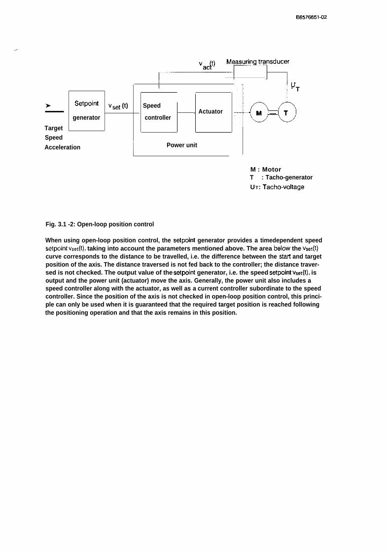
Fig. 3.1 -2: Open-loop position control
When using open-loop position control, the setpoint generator provides a timedependent speedsetpoint Vset(t), taking into account the parameters mentioned above. The area below the vset(t)curve corresponds to the distance to be travelled, i.e. the difference between the starl and targetposition of the axis. The distance traversed is not fed back to the controller; the distance traver-sed is not checked. The output value of the setpoint generator, i.e. the speed setpoint Vset(t), isoutput and the power unit (actuator) move the axis. Generally, the power unit also includes aspeed controller along with the actuator, as well as a current controller subordinate to the speedcontroller. Since the position of the axis is not checked in open-loop position control, this princi-ple can only be used when it is guaranteed that the required target position is reached followingthe positioning operation and that the axis remains in this position.

BS576651-02
Measuring transducerIncrements
1
dac+t) Measuring transducer
Vac{t) ‘ T
I I , /
Setpointgenerator
YTargetSpeedAcceleration
I 1: I J
Power unit
M : MotorT : Tacho-generatorUT : Tacho-voltaged : Distance
Fig. 3.I-3: Closed-loop position control
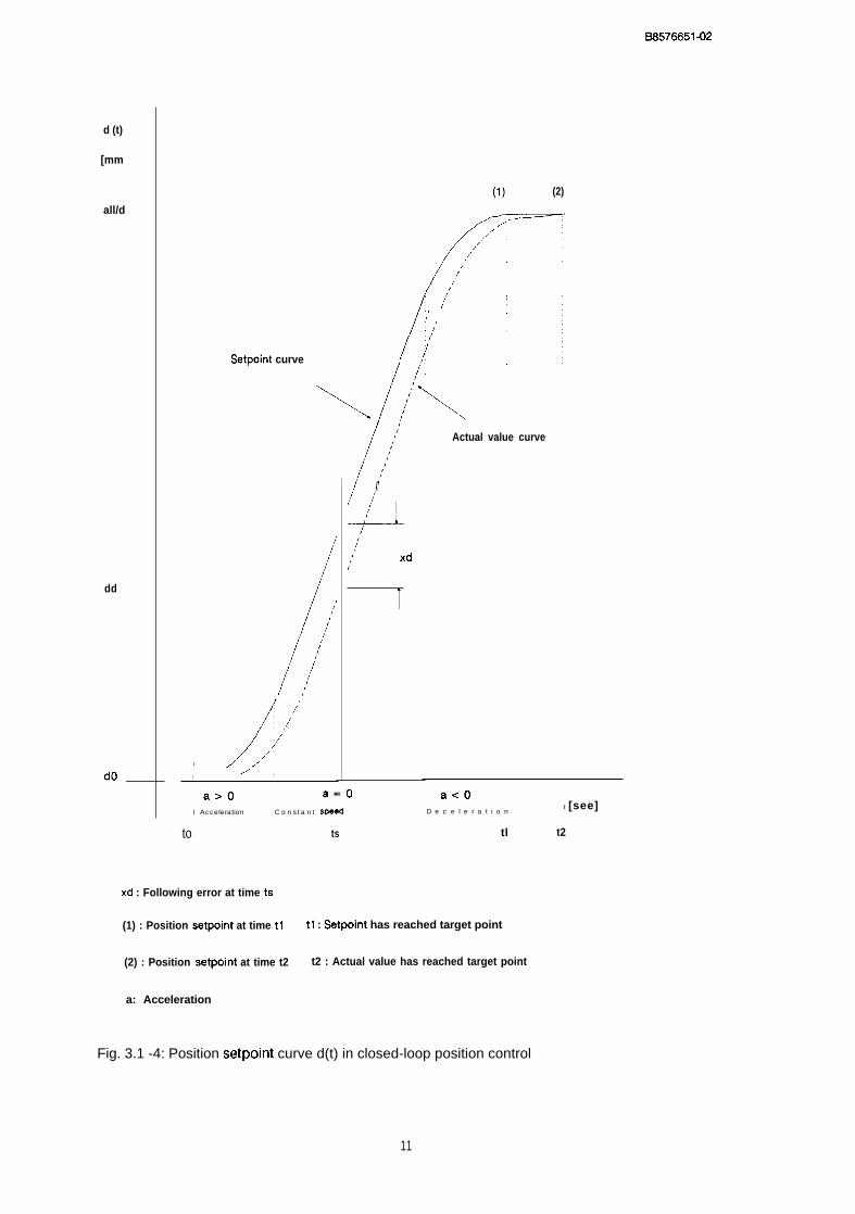
In closed-loop position control, the output value of the setpoint generator is the position setpointds~t(t). The actual position value is continuously measured and fed back. This is compared withthe position setpoint generated by the setpoint generator. Deviations are detected during thewhole traversing movement. These deviations (w) are supplied to a position controller, whichoutputs a speed setpoint vset(t). This output value is changed by the position controller duringthe positioning operation so that the actual position value follows the distance curve generatedby the setpoint generator as exactly as possibie. This ensures that the required target position ofa traversing movement is reached. The final position is maintained, since disturbances are recog-nized by the position controller and compensated.
In CIOSed-IOOp position control, the actual position value dact(t) always lags behind the positionsetpoint dset(t) during the positioning operation. The difference between the setpoint and actualvalue is the following error xtj. The following error must be optimized for the particular applica-tion by suitable assignment of parameters to the position controller and by suitable selection ofthe speed, acceleration and deceleration.
The following figure shows the two position curves (position setpoint and actual position value)for a ciosed-loop position control operation.
,...7
10
B8576651-02
d (t)
[mm
all/d
dd
dO–
(1) (2)
/
/’,,f
/
/ ‘/’
(’,’./’,/(
Setpoint curve /:
,1 :
\ /<
/’,{
,’/’
/’(’
4-,’
I
/’/’(’
/’/’
,’;
/’
/
/’,/’
!/”/,’
/,.
/’/( xd
;
i
Actual value curve
I/,
1; a>O a=l) aeOI Acceleration C o n s t a n t sped D e c e l e r a t i o n
t [see]
to ts tl t2
xd : Following error at time ts
(1) : Position setpoint at time tl tl : Setpoint has reached target point
(2) : Position setpoint at time t2 t2 : Actual value has reached target point
a: Acceleration
Fig. 3.1 -4: Position setpoint curve d(t) in closed-loop position control
11

The relationship between the acceleration or deceleration a(t), speeds, v(t) and the correspon-ding distances d(t) in closed-loop position control is illustrated below.
a(t)
v(t)[mm/min]
$(1]SI
o
dl+ d2
I,
tII
!
I,I
I!!
I11
I
,
II
1
1
1
1
1
I II IIII II
I ,1 ,$
t(J tl tz t3‘ 1 td ts\
$
—
—
—
—
/
—
,II
,
II
I
—
—
—
/
—
/’”
,I
,
!
I
I
~
,I-
I
I
1s~,ItI
1
I,
III
,(
t
I!
1
I,
!
,
t,
1
1
I,II
t(s)
I
II1
Z2Dt{ tll t(s)
d 1 + d z+ d3
t(s)
1---
I
,.-%.,
Fig. 3.1-5: Relationship between acceleration or deceleration, speed and distance
BS5766514)2
Instead of generating the position setpoint d~~t(t) in the setpoint generator, a different principleof closed-loop position control involves supplying the total difference between the current posi-tion and the required target to the position controller. Parameters, e.g. the traversing speed orthe acceleration, which determine the positioning operation, are then not taken into account bythe position controller. Using this principle, the output value of the position controller, i.e. thespeed setpoint, is limited accordingly.
If there is also a speed and current controller in addition to the position controller, the controlloop contains three secondary loops. The effects of such a system can generally be modified bydifferent mutually interactive parameters.
The following conditions must therefore be fulfilled:
● the power unit and the motor must be carefully matched with each other,● the drive must have a sufficient power reserve,● the drive is exactly adjusted,● the individual parameters are carefully determined and matched to the situation and● there is no backlash within the position control loop.
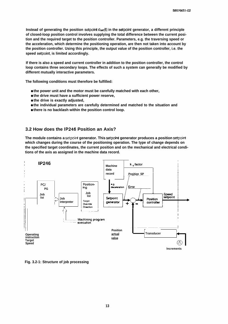
3.2 How does the IP246 Position an Axis?
The module contains a setpoint generator. This setpoint generator produces a position setpointwhich changes during the course of the positioning operation. The type of change depends onthe specified target coordinates, the current position and on the mechanical and electrical condi-tions of the axis as assigned in the machine data record.
,I
I IP246Machine k “factor I
1dataI
t record, Position SP,III Pc/ Position- e.g,(I PG ing1 v1 Job Job
I list listI > Job Setpoint1 interpreter Target1 O#erride 1I A Oirecticn
~ ]L~a-~ramOperatinginstructionTargetSpeed
Positionactualvalue
I1
I1
1
,
. - --. ——-———— ————-—— ———————————— :
Transducer
@Increments
Fig. 3.2-1: Structure of job processing
13
B6576651-02
Traversing jobs received via the PG or PC interface are entered in the appropriate job list. Thejob interpreter generates positioning jobs from these and sends them to the setpoint generatorfor processing. Each axis can only process one job at a time.
Depending on the conditions stipulated in the machine data (e.g. acceleration, deceleration, ...),the setpoint generator supplies the current position setpoint at fixed intervals (the samplingtime). The position controller operates using the same clock pulse. It generates a speed setpointoutput signal from the difference between the position setpoint and the current actual positionvalue using a suitable algorithm. This output signal is sent as a setpoint to a speed controller(subordinate to the position controller) located in the power.
The control algorithm of the position controller is a P-algorithm (proportional controller) in theIP246. The error or the following error Xd is obtained from the difference between the position set-point and the actual position. The speed setpoint is obtained by multiplying this error by a gain(kv) factor selected in the machine data record. This speed setpoint is output as an analog valuevia a digital-to-analog converter. The output voltages are in the range +/- 10 volts.
For the position controller, therefore, the total difference between the start position and thetarget point is not relevant as the control error. The position setpoint approaches the target pointstep by step. If the actual position value lags behind, this results in an error (following error)which the position controller attempts to compensate. This algorithm is illustrated in the follo-wing flow diagram.
(’-?4. 3..,>~,. fy
14
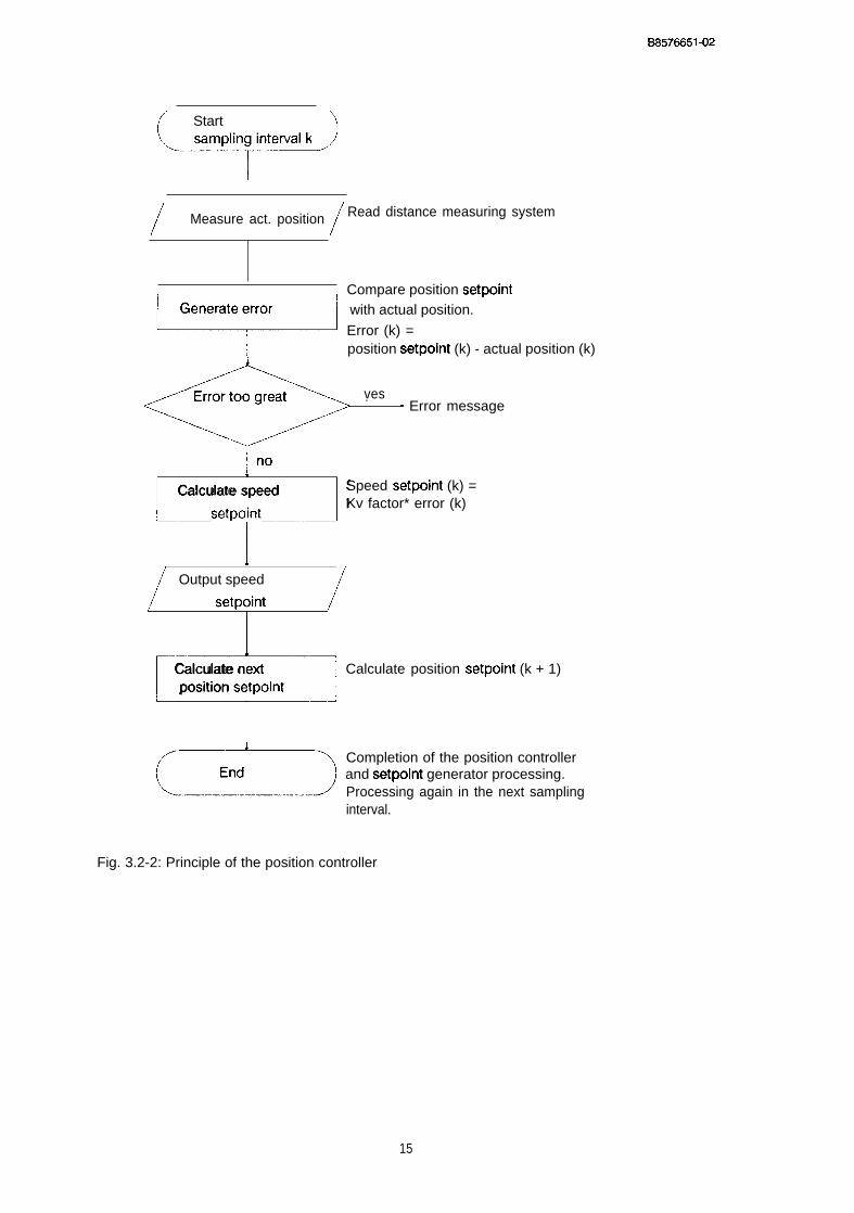
6S576651-02
/’ Start )
/Measure act. position
/Read distance measuring system
Error too great .“ Error message
no
~
Calculate speed Speed setpoint (k) =
setpointKv factor* error (k)
i
/ Output speed /
I
7Calculate nextposition setpoint
Compare position setpointwith actual position.
Error (k) =position setpoint (k) - actual position (k)
ves
Calculate position setpoint (k + 1)
Completion of the position controllerand setpoint generator processing.Processing again in the next samplinginterval.
Fig. 3.2-2: Principle of the position controller
15
BS576651-02
,...?.,.,.
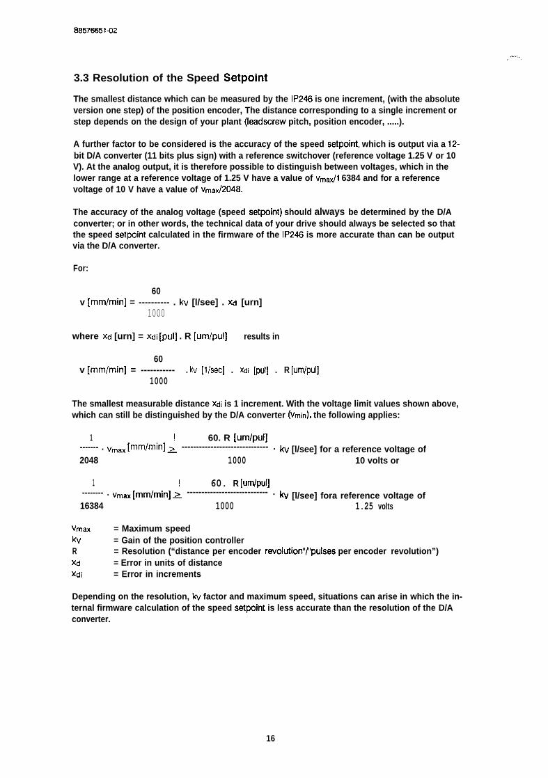
3.3 Resolution of the Speed Setpoint
The smallest distance which can be measured by the IP246 is one increment, (with the absoluteversion one step) of the position encoder, The distance corresponding to a single increment orstep depends on the design of your plant (Ieadscrew pitch, position encoder, .....).
A further factor to be considered is the accuracy of the speed setpoint, which is output via a 12-bit D/A converter (11 bits plus sign) with a reference switchover (reference voltage 1.25 V or 10V). At the analog output, it is therefore possible to distinguish between voltages, which in thelower range at a reference voltage of 1.25 V have a value of Vmtil 6384 and for a referencevoltage of 10 V have a value of vmax/2048.
The accuracy of the analog voltage (speed setpoint) should always be determined by the D/Aconverter; or in other words, the technical data of your drive should always be selected so thatthe speed setpoint calculated in the firmware of the IP246 is more accurate than can be outputvia the D/A converter.
For:
60v [mm/min] = ---------- . kv [l/see] . xd [urn]
1000
where Xd [urn] = Xdi [pul] . R [um/pul] results in
60v [mm/min] = ----------- . kv [1/SE?C] . )(di [pld] . R [Um/pUl]
1000
The smallest measurable distance Xdi is 1 increment. With the voltage limit values shown above,which can still be distinguished by the D/A converter (vmin), the following applies:
1 ! 60. R [um/pul]------- . vmax [mm/min] ~ ------------------------------ . kv [l/see] for a reference voltage of2048 1000 10 volts or
1 ! 60. R [um/pul]-------- . vmax [mm/min] > ---------------------------- . kv [l/see] fora reference voltage of16384 1000 1.25 volts
Vmax = Maximum speedkv = Gain of the position controllerR = Resolution (“distance per encoder revolution’’t’pulses per encoder revolution”)Xd = Error in units of distancexdi = Error in increments
Depending on the resolution, kv factor and maximum speed, situations can arise in which the in-ternal firmware calculation of the speed setpoint is less accurate than the resolution of the D/Aconverter.
16
B8578851-02
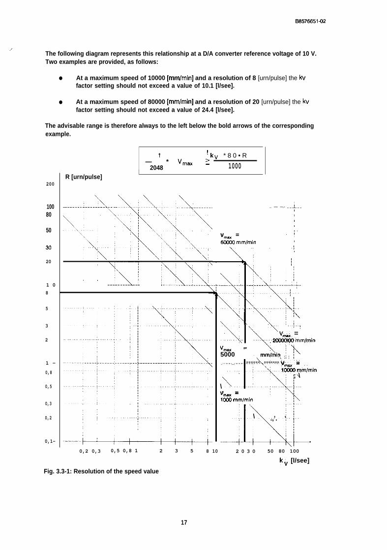
.’The following diagram represents this relationship at a D/A converter reference voltage of 10 V.Two examples are provided, as follows:
● At a maximum speed of 10000 [mm/min] and a resolution of 8 [urn/pulse] the kvfactor setting should not exceed a value of 10.1 [l/see].
● At a maximum speed of 80000 [mm/min] and a resolution of 20 [urn/pulse] the kvfactor setting should not exceed a value of 24.4 [l/see].
The advisable range is therefore always to the left below the bold arrows of the correspondingexample.
1 ! kv * 8 0 • R— * Vmm ~
2048— 1000
200
10080
50
34)
20
1 08
5
3
2
1 -
0,8
0,5
0,3
0,2
0,1-
R [urn/pulse]I
,, ., \
., bi.
1. . —- —.- —--!——
!
!
1
I
,
v = ,1
& mm/min1
I
\ “’ ““ “;’tA . (
.!..,
K‘y,,.—-—— _-+. ------- .---+ -.i......~....;<“<\.:. . . . . . . . . . . ..;\
\,, : [ f?\ ...:. ...!
‘k.vti~ =
:x. .., M rnm)min
Vm = : ! ‘-k5000 mm/min : I ~_________
\
““’I: ”:%.....
------ ------- v =l&&3rnm/min.,
\
; \
v =1%6 mm/min ;,, ~
M;
\
\ .,.; .,’. ’ I
+0,2 0,3 0,5 0,8 1 2 3 5 8 10 2 0 3 0 50 80 100
kv [l/see]
Fig. 3.3-1: Resolution of the speed value
17
B6576651-02
4 Machine Data and their StructureBefore a positioning module such as the IP246 can execute a positioning operation automatical-ly, it must be provided with information about the connected drive, the position measuringsystem etc. This information is known as machine data. Machine data is stored in a data block.This has a constant length and can be divided into the following parameter groups:
● axis type● Position measurement and resolution,● traversing range,● speeds,● acceleration rates,● controller parameters● correction parameters (offsets) and● other parameters.
Using the COM246 software package, machine data records can be generated efficiently andeasily at the programmer and transferred to the positioning module. Once on the module theycan be read again, corrected or deleted. Both COM246 and the module perform consistencychecks. If machine data are sent to the IP246 via the PC interface, they are only checked by theIP246. It is therefore possible to assign bad machine data to an axis on the module.
Bad in this case means that either data in the machine data record exceed the stipulated limitvalues, or that certain combinations of machine data are not permitted.
If a bad machine data record is transferred to the positioning module, the IP246 signals the error“error in machine data” via the PG and PC interface. The type of error itself, e.g. “wrong axis ormodule number” is stored by the firmware of the positioning module in the machine data block(=> “plannin9, Installation and Service, Installation Guide”). If you enter the machine data usingthe COM246 software package, the type of machine data error is displayed in plain text in theerror message line on the PG. The message “error in machine data” is then overwritten.
If you wish to position using both axes of the IP246, a machine data block (DB) must be presenton the module for each axis. Axis 1 and axis 2 can be assigned a machine data block with thesame DB number.
If no correct machine data are stored on the IP246 for an axis, the axis is not operational. The po-sition controller remains disabled and the operational signal IIFUM” is not set. If operating instruc-tions are sent to the axis, the job is rejected with the error message “wrong or no machine data”.
If you edit the machine data record using the COM246 software package, all the requiredmachine data are requested in plain text using a menu technique. Following the input field, thedefault dimensional unit and the permitted range of values is displayed. This is explained in detailin *’Communications Software COM246, User’s Guide”.
,/#@-.:%,. ..,,..,,’.’
Since no special software is available for planning the machine data in the CPU, the followingdescription of the individual machine data includes the data formats as required for entry orstorage in the CPU. A table in “Standard Function Blocks FB164 and FB165, User’s Guide” provi-des an overview of these formats.
..,. .’
18
BS576651-02
DW n +0
DW n + 5
DW n +64
Last data word
Data header
Machine data
Used by theabsolute versionof the IP246
Length: 140 bytes
Any number(except D13 164 and DB 165)
Fig. 4-1: The machine data record in the CPU
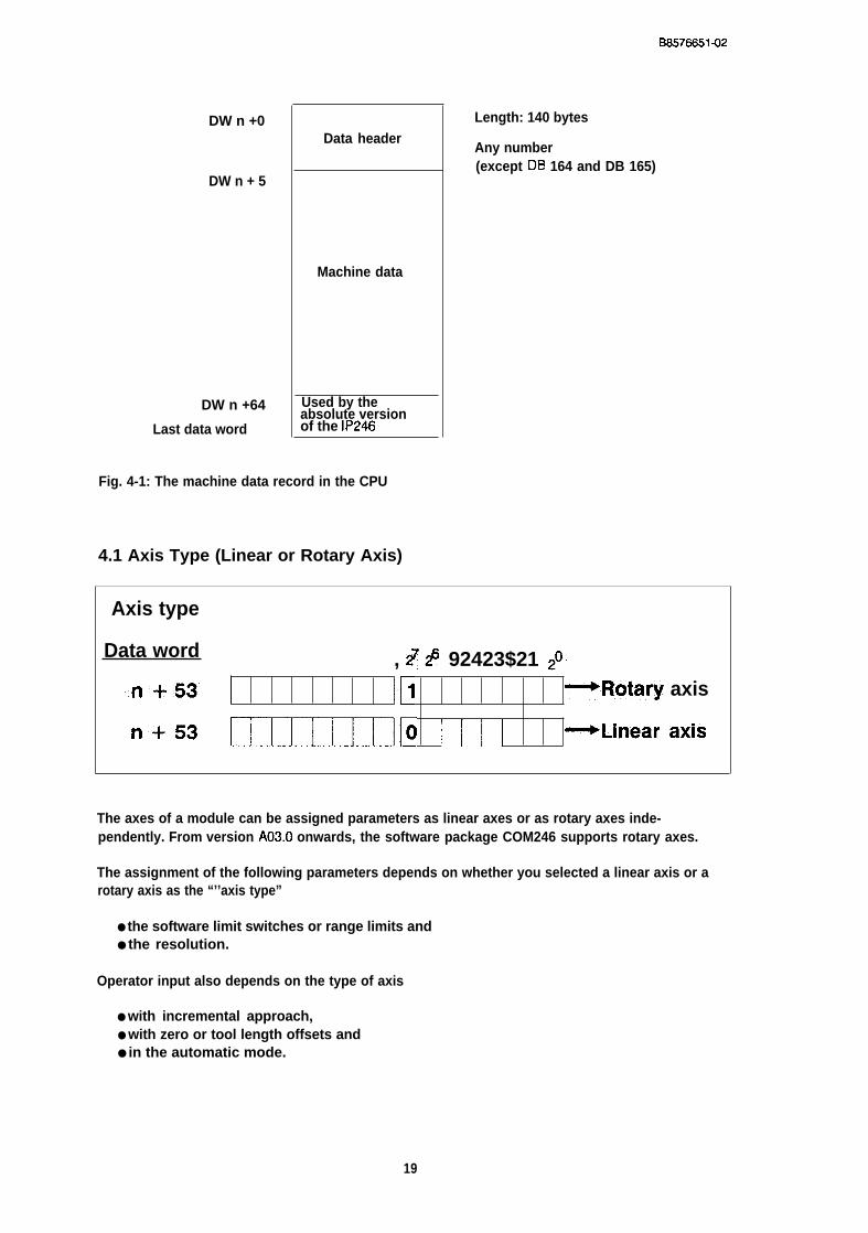
4.1 Axis Type (Linear or Rotary Axis)
Axis type
Data word , ~ # 92423$21 #
..n + .53” Ill -.Rotary axis
‘+53 CmIIItllo 1111 -Linear axis
The axes of a module can be assigned parameters as linear axes or as rotary axes inde-pendently. From version A03.o onwards, the software package COM246 supports rotary axes.
The assignment of the following parameters depends on whether you selected a linear axis or arotary axis as the “’’axis type”
● the software limit switches or range limits and● the resolution.
Operator input also depends on the type of axis
● with incremental approach,● with zero or tool length offsets and● in the automatic mode.
19
SS576651-02
. . . . . . . . .
These differences are explained in detail in the appropriate section. Some fundamental aspectsare, however, discussed below.
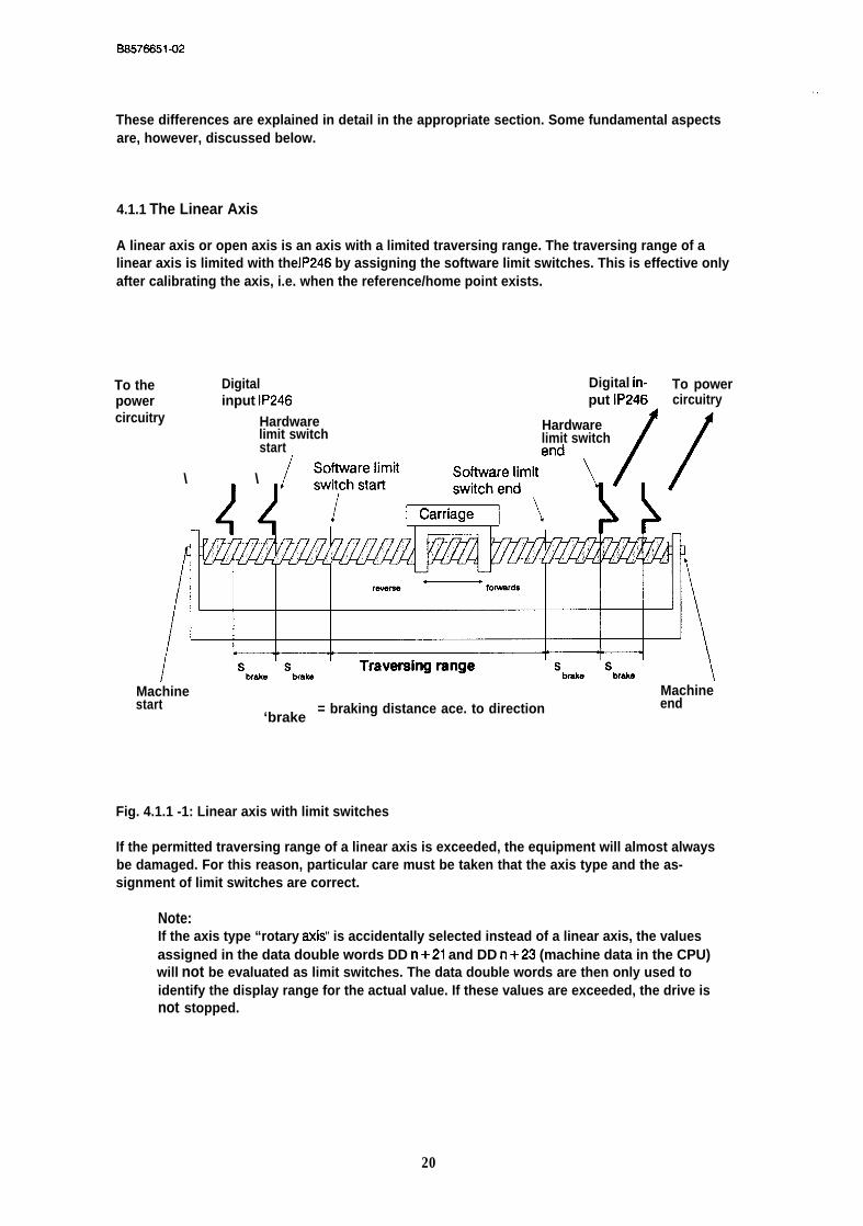
4.1.1 The Linear Axis
A linear axis or open axis is an axis with a limited traversing range. The traversing range of alinear axis is limited with the IP246 by assigning the software limit switches. This is effective onlyafter calibrating the axis, i.e. when the reference/home point exists.
To the Digital Digital in-power input IP246 put IP246
To powercircuitry
circuitry
\ \
Hardwarelimit switch
Hardware
startlimit switch
Machine Machinestart
‘brake= braking distance ace. to direction end
Fig. 4.1.1 -1: Linear axis with limit switches
If the permitted traversing range of a linear axis is exceeded, the equipment will almost alwaysbe damaged. For this reason, particular care must be taken that the axis type and the as-signment of limit switches are correct.
Note:If the axis type “rotary axis” is accidentally selected instead of a linear axis, the valuesassigned in the data double words DD n+21 and DD n+23 (machine data in the CPU)will not be evaluated as limit switches. The data double words are then only used toidentify the display range for the actual value. If these values are exceeded, the drive isnot stopped.
20
BS576651-02
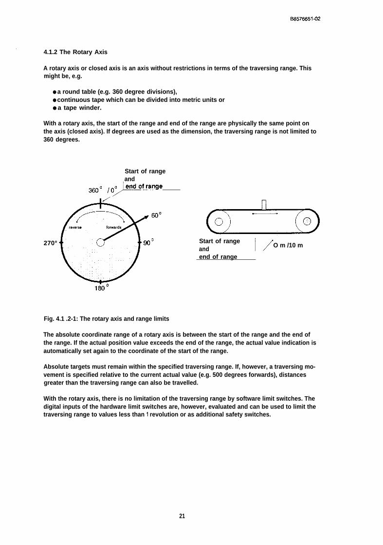
.,4.1.2 The Rotary Axis
A rotary axis or closed axis is an axis without restrictions in terms of the traversing range. Thismight be, e.g.
● a round table (e.g. 360 degree divisions),● continuous tape which can be divided into metric units or● a tape winder.
With a rotary axis, the start of the range and end of the range are physically the same point onthe axis (closed axis). If degrees are used as the dimension, the traversing range is not limited to360 degrees.
Start of rangeand
360” K’”
270° Start of rangeand 1/O m /10 m
end of range
Fig. 4.1 .2-1: The rotary axis and range limits
The absolute coordinate range of a rotary axis is between the start of the range and the end ofthe range. If the actual position value exceeds the end of the range, the actual value indication isautomatically set again to the coordinate of the start of the range.
Absolute targets must remain within the specified traversing range. If, however, a traversing mo-vement is specified relative to the current actual value (e.g. 500 degrees forwards), distancesgreater than the traversing range can also be travelled.
With the rotary axis, there is no limitation of the traversing range by software limit switches. Thedigital inputs of the hardware limit switches are, however, evaluated and can be used to limit thetraversing range to values less than 1 revolution or as additional safety switches.
21
BS576651-02
4.2 Position Decoding and Travel Resolution
Depending on whether the position is encoded by an incremental or an absolute positionencoder, the following parameters affect position decoding and travel resolution:
● dimensional unit● Puke evaluation for incremental position encoder,● number of revolutions of an absolute position encoder,. Pulses/steps of the position encoder per encoder revolution and● distance travelled per encoder revolution.
The last two parameters determine the resolution. This is a relationship between the positionencoder signals and the corresponding distance travelled on the axis.
The specification ‘Yorwards” or “clockwise” always indicates the direction which leads to the posi-tion encoder turning in a clockwise direction, the specification “reverse” or “anti-clockwise”always indicates the direction which leads to the position encoder turning in an anti-clockwise di-rection.
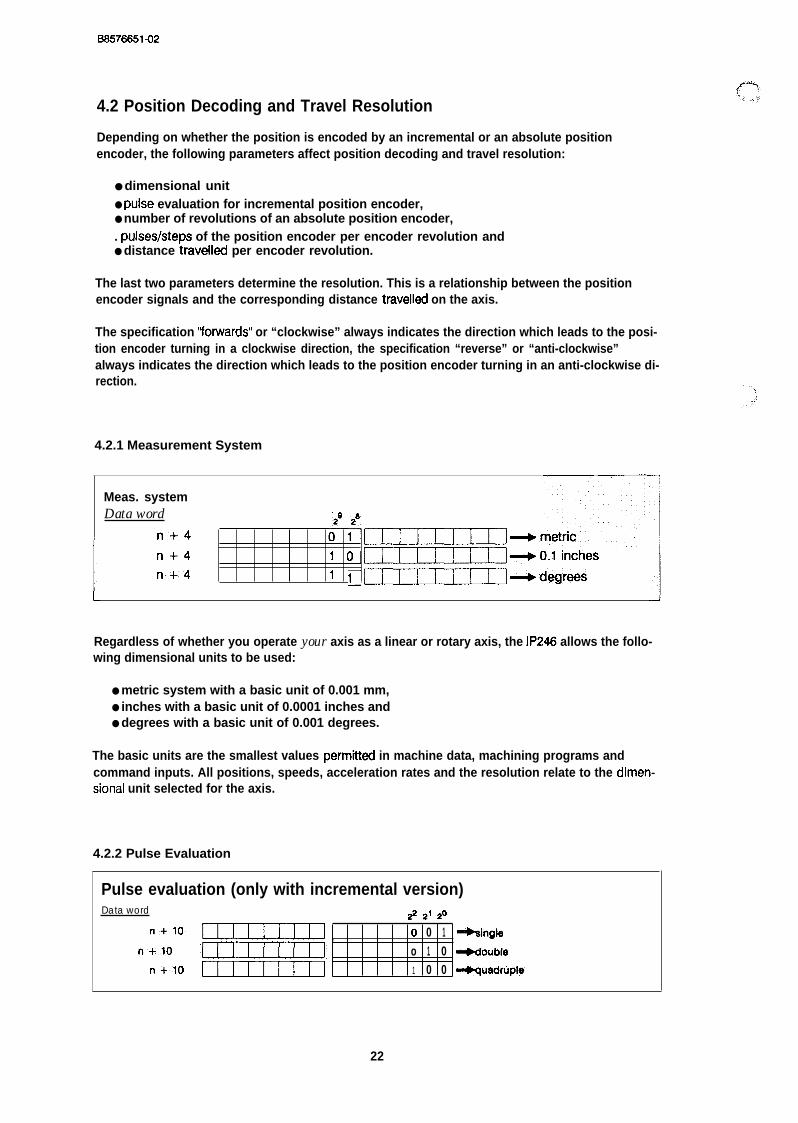
4.2.1 Measurement System
Meas. systemData word
n+47: :- UzECEUJ~m@ric
n+4 1 0.CEUzU3J-ol inchesn+4 1 1:~~d~rees
Regardless of whether you operate your axis as a linear or rotary axis, the IP246 allows the follo-wing dimensional units to be used:
● metric system with a basic unit of 0.001 mm,● inches with a basic unit of 0.0001 inches and● degrees with a basic unit of 0.001 degrees.
The basic units are the smallest values perm”tied in machine data, machining programs andcommand inputs. All positions, speeds, acceleration rates and the resolution relate to the dimen-sional unit selected for the axis.
4.2.2 Pulse Evaluation
Pulse evaluation (only with incremental version)Data word # 21 ~o
‘+1”” UQIIIIJ , 0 0 1 -%ingle
“+1” CIImmI? o 1 0 4ouble
“+1” Uuuul 1 0 0 ~uadruple
22

B8578651-02
In the incremental version of the positioning module, two pulse trains (signal A and signal B) witha 90 degree phase displacement are evaluated (see “Hardware, Instructions”). The direction ofrotation of the position encoder and therefore the drive is established from the order in whichsignals A and B are detected. The distance travelled is determined by counting the signal edges.
There are three possible types of evaluation as follows:
Single evaluation: only the rising edges of the pulse train of signal A are countedDouble evaluation: both edges of pulse train A are countedQuadruple evaluation: both edges of pulse A and of pulse B are counted.
Single evaluation:
Signal A
1 Signal B
, Internal count pulset
Double evaluation:
ml Signal A
Signal B
Ist 2nd fl 3rd Increment1! Internal count pulse
t
Quadruple evaluation:
__.__j~signa’A1 rlsig-
Internal count pulset
Fig. 4.2.2-1: Pulse evaluation
An increment is the distance between two consecutive internal counter pulses.
With the absolute version, no multiplication of the pulses is possible.
23
BS576651-02
4.2.3 Resolution
Pulses per encoder revolution‘Data word,
ri’+”~ “ .~~
n+?; “QZIUIH3UIEECII Range of values 1(2)...S5000 : ::’
~ Distance travelled per encoder revolutionData word
n + ~ mIIIQ3cmIImIJ
n’+’”= ‘ILIIuImUImJzIl *ng”ofva’””s l - -
The resolution is a relationship between the position encoder signals and the position of its axis.
Note:If you use double or quadruple evaluation with the incremental version, the resolutiondepends on the edges to be evaluated, not to the actual pulses of the position encoder.
The range of values of the resolution is always as follows:
0.1 to 99.9 mm per 1000 pulses.
The same applies to degrees and units of 0.1 inch. With the absolute version, the upper limit isnot 99.9 but 100.
Example:A rotary incremental position encoder has 1000 pulses per revolution. If it turns once, this means3 mm travelled. This information can be used as it stands for single evaluation. This results in aresolution of 3 urn per pulse or 3 mm per 1000 pulses. If you select double evaluation, the resolu-tion is then 1.5 mm per 1000 pulses. With quadruple evaluation, the resolution would be 0.75mm per 1000 pulses.
The resolution is, however, not specified directly but in the form of two values. These areasfollows:
● “distance travelled per encoder revolution” in the selected basic unit and● “pulses/steps per encoder revolution”
The resolution [urn/pulse] is obtained by dividing these two values.
The value “distance travelled per encoder revolution” takes into account any gearing betweenthe position encoder and axis. The following range of values is possible:
0.001...400.000.
This means that you can assign values of 1 urn to 400 mm per encoder revolution in metric units,0.001 to a maximum 400 degrees per encoder revolution using degrees as the unit and 0.0001inch to 40 inches when using inches.
24
I
BS576651-02
The range of values for “pulses/steps per encoder revolution” is as follows:
● 1 . . . 65000 for the incremental version and● 2...65000 for the absolute version.
With the incremental version, you must refer “pulses per encoder revolution” to the edges to beevaluated and not to the actual pulses of the position encoder. [f, for example, you have a posi-tion encoder with 1000 pulses per revolution and quadruple evaluation for “pulses per encoderrevolution”, you must enter 4000 and not 1000. Despite this large range of values, the actual reso-lution is limited to the range described above.
Restrictions with the absolute versionWhen you specify the parameters “distance travelled per encoder revolution” and “steps/pulsesper encoder revolution” with the absolute version, you must always refer to a single and com-plete revolution of the position encoder. If parameters for a rotary axis are assigned with the ab-solute version and a multi-turn position encoder is used, you must remember that you can onlyenter the distance travelled per encoder revolution with three decimal places.
Example:A multi-turn absolute position encoder with 256 revolutions and 1024 steps per revolution is con-nected to a round table with a ratio of 1 :256. One revolution of the round table is 360 degrees.This results in a distance travelled per encoder revolution of
360 [degrees]---------------------------- = 1.40625 [degrees/revolution],256 [revolutions]
which cannot be entered.
With the absolute version, there is always a close relationship between the position encoder (re-solution) and the assigned traversing range. For more information, refer to Section 4.3 ‘The Tra-versing Range”.
Restrictions with the incremental versionWhen assigning the parameters “distance travelled per encoder revolution” and “pulses perencoder revolution” for a rotary axis with the incremental version, you must also refer to a singlecomplete revolution of the position encoder. Only then is the reference point reproducible duringthe reference point approach. The parameter “pulses per encoder revolution” indicates thenumber of edges of the encoder signal to be evaluated and not the number of pulses per posi-tion encoder revolution.
For the incremental version, an additional data word DW n + 11 is provided in the machine datarecord for the resolution, which also appears in the software package COM246 in the machinedata. A value entered in this field has no significance. If machine data are generated or editedwith the COM246 software package, a value within the specified limits must nevertheless beentered in this input field. The actual value of the resolution is calculated from the two values dis-cussed above.
Even with a resolution greater than 1 urn per pulse, positions can be entered accurate to 0.001mm. Values which can no longer be distinguished owing to a less accurate resolution are auto-matically rounded up or down by the positioning module. This also applies to the other dimensio-nal units.
25

B6576651-02
4.2.4 Decoding and Evaluation of the Absolute Encoder Value
Number of encoder revolutionsD&ta’’wOr~:’
““n +~ CEEEUMCUUDJ3‘ n +55 UIIIU33CEUHIII Range of values 1,..65000
Number of steps per encoder revolutionData word
.:n+ = UmIzc13clmIUIl
“n”’+57 UmIIIIl~ Range of values 2...65000
An absolute position encoder is described by the two following parameters:
● “number of encoder revolutions” and● “number of steps per encoder revolution”.
Both single-turn position encoders (number of revolutions = 1), and multi-turn position enco-ders (maximum 6500 revolutions) can be connected, The total number of steps of the absoluteposition encoder is obtained from the product of the two parameters. This is restricted to 220.The absolute version of the IP246 only processes signals from encoders which produce Graycode or Gray excess X code. A Gray code cannot be processed in BCD.
A Gray excess X code is a form of Gray code in which the same number of steps of the code areomitted in both the lower and upper range; the required number of steps is “cut out” of the nexthigher power of 2. The Gray code then remains single step even with a zero crossing.
Example:Required number of steps = 12. The next power of 2 is 16 (24)= > the code disk of the position encoder is a disk with 16 positions of which two have beenomitted in the upper and two in the lower range. This is a Gray excess X code, whereby X standsfor the number of steps omitted at one end.
,.!,,
‘?
In this example: Gray 16 excess 2 code.
26

Track
BS576651-02
4 3 2 1 Value1
(o)(1)
(2)
(3)
(4)
(5)
(6)
(7)
(8)
(9)
(lo)
(11)
(12)
(13)
(14)
(15) d!!#j = Signal 1
= Signal O
Fig. 4.2.4-1: Gray excess X code
The module automatically calculates a Gray excess value (if used), i.e. without any specific entryin the machine data record. If the total number of steps assigned is not equal to a power of 2, itis assumed that an absolute position encoder with a Gray excess X code is being used.
Note:To obtain a correct actual value from the signals of the absolute positionencoder, the parameters
- “number of encoder revolutions” and- “number of steps per encoder revolutions”
must be correct in the machine data record.
The maximum number of steps of the absolute position encoder being used must be absolutelyidentical to the assigned maximum number of steps resulting from the multiplication of these twoparameters.
27

B8576651-02
If an absolute encoder count occurs during operation which cannot occur with the parametersassigned for the absolute position encoder or which is outside the usable range with a referencepoint set (= > Section 4.3 “The Traversing Range”), e.g. because the actual total number ofsteps of the absolute position encoder is greater than the assigned total number of steps, theerror message “illegal absolute encoder reading” is output and the control system changes tothe following error.
If an absolute encoder is used with a total step number less than the assigned total number ofsteps, this encoder does w supply an illegal value. During operation, however, this may lead toa jump in the actual value, (zero crossing of the encoder), which is not permitted at this point. Ifthe jump is sufficiently large, the error message “illegal change of absolute encoder value” isoutput and the module changes to the following error mode.
In these two exceptional cases, the following error mode can also be terminated by changingthe machine data record (= > “Functions, Reference Manual”; 6ection 3.3 “Following ErrorMode (Operating Mode 4)”.
28

I
BS576651-02
4.3 The Traversing Range
iReference point/home point
Data word
n+lg UUIIIIIUIUIIIJ
n+~ CUICIIDCUIHI13 Range of values+- 40000 mm
Start of range (software limit switch start)Data word
n+21 UIEIEIOUIIHIII
n+zz UIEEUIICEUDIII Range of values +- 40000 mm
End of range (software limit switch end)Data word
n + 2 3 UHIIIEIUIIIIIE
n + 2 4 CUEIIEl~ Range of values +- 40000 mm
All distances are specified in the dimensional unit selected in the “measurement system” parame-ter. The traversing range is characterized by the following:
● the start of the traversing range (software start limit switch),● (software end limit switch) and● the reference or home point coordinate.
For a linear axis, the start of the traversing range is the software start limit switch and the end isthe software end limit switch. Targets can only be approached within this range. If a softwarelimit switch is tripped during operation, the axis is braked with the deceleration selected for theparticular direction in the machine data record.
Example rotary axis:A round table is divided into 380 degrees. The start of the range is at O degrees, and the end ofthe range at 360 degrees. O and 360 degrees are the same point on the round table and canboth be specified as the target coordinate.
When using degrees, the traversing range is not necessarily from O degrees to 380 degrees. Itmay, e.g. be from 400 degrees to 800 degrees. The only restrictions are the numerical range ofthe individual parameters and the rule that the coordinate for the start of the range must besmaller than the coordinate for the end of the range.
The reference point with the incremental version of the IP248 corresponds to the home pointwith the absolute version. Both are used to calibrate the axis. With the reference point approach,or when setting reference or home points, the reference or home point is assigned the coordina-te value stored in the machine data record. With this, the machine zero point is also fixed, the
08576651-02
software limit switches on the linear axis are evaluated and absolute positions can be approa-ched.
The traversing range must beat least twice as great as the resolution (“distance travelled perencoder revolution’ ’/’’pulstepsteps per encoder revolution”). If this is not the case, “wrong resolu-tion” is entered in the data record.
Example:For a resolution of 4 urn/increment, the traversing range must be at least 8 um.
4.3.1 Restrictions for the Absolute Version
With the absolute version of the IP246, there is a close relationship between the traversing rangeand the data of the position encoder used and the resolution.
For a linear axis
Each point which can be physically reached by the axis must be covered “uniquely’ by the abso-lute position encoder, i.e. no encoder reading can occur twice. This means the following:
[distance travelled per encoder revolution] . [number of encoder revolutions]
must at least correspond to the physical length (from limit stop to limit stop) of the axis.
The machine data record contains no information about the physical limits of the axis or the posi-tion of the hardware limit switches. The traversing range is delineated solely by the coordinatesof the software limit switches. This means that it is possible to use a particular section of a givenaxis as the traversing range and to use an absolute position encoder which does not cover thetotal physical length of the axis uniquely. Under the following conditions, it is also possible toensure that no incorrect (not unique) actual value is detected ( = > “Functions, ReferenceManual”, Section 3.4.3 “Setting the Home Point”):
1.) When the hardware limit switches are installed with a clearance corresponding to the brakingdistance
Vmax2 [mm2/min2]dtxakel [mm] = . . . . . . . . . . . . . . . . . . . . . . . . . . .
2.a [mm/d2].3600
from the software limit switches. Whereby dtxakel is the required braking distance, Vmax themaximum speed as stipulated in the machine data and a is the deceleration forwards or back-wards.
2.) When the second hardware limit switches, which directly influence the power unit, are positio-ned with a clearance corresponding to the braking distance
Vmaxz [mm2/min2]dbrakez [mm] = ---------------------------------
2.amw [mm/d2].3600
“-3,,, +:;
,.,,
behind the first hardware switches. Whereby, dbrakez is the maximum required braking distanceat maximum deceleration, vrnax is the maximum speed stipulated in the machine data and arnaxthe maximum deceleration.
30

BS576651-02
Remember that all braking distances can be extended by a maximum of
d~o~r = v~,. [mm/min] / 8000
This value results from the response time of the firmware.
When the machine data are input, the firmware of the IP246 checks whether the positionencoder covers at least the following:
Traversing range (defined by the software limit switches)plus2.dbr&el in the forwards directionplus2.dbrakel in the reverse directionplusa.dcorr
This value will be called the usable range from now on.
The range covered by the position encoder can, of course, be greater than the usable range. Inthis case, only part of the range of the absolute position encoder is used. The zero crossing ofthe position encoder can lie within this range, outside it or exactly on a software limit switch.
If the range uniquely covered by the encoder is exceeded during operation, the correct actualposition will still be detected, although a unique actual value can no longer be expected from theabsolute position encoder. This information is, however, lost following a power down (failure ofthe battery back up from the PC or removal of the module).
For a rotary axis
If the axis type rotary axis is specified, the traversing range (end of range - start of range) mustmatch exactly the range covered by the absolute position encoder. The end of the range descri-bes the same physical point as the start of the range. This means that the absolute positionencoder must once again supply the same value when the whole traversing range has been tra-velled once.
The following equation must apply:
IDistance travelled per encoder revolution] . [number of encoder revolutions] = [range end -range start].
31

B6576651-02
4.3.2 Restrictions for the Incremental Version
If a rotary axis is selected with the incremental version of the IP246, the traversing range (end ofrange - start of range) must be in an even ratio to the number of pulses per revolution of the in-cremental position encoder and to the distance travelled per encoder revolution to be able to re-produce the reference point.
The following must apply:
Traversing range [urn] / distance traveikd per encoder revolution [urn/rev] = n [rev]
The following general restrictions apply to the coordinates:
● All coordinates must be in the range +/-40 m (+/- 4000 inches; +/- 40000degrees).
● The coordinate value from the end of the range (software end limit switch) must begreater than the coordinate value of the start of the range (software start limitswitch).
● The reference coordinate must be between or exactly on the software limit switchesor limits of the range.
4.4 Speeds
SpeedsData word
n + 3 5 UIIIUEIUIIIIZE
To data word
n+49 CUUUEICCUEUEI
n +~ CUEUIIICUUIIII ~n9eofvalues16~
(for the absolute version up to data word n + 45/n + 46)
Speeds for the various modes are assigned in the machine data record. The speeds must be se-lected as follows, depending on the selected dimensional unit:
● in mm/min for metric input,● in 0.1 inch/rein for dimensions in inches or● in degrees/rein for dimensions in degrees
The maximum range of values is 1 to 65000.
32
BS576651-02
The starting point is the maximum speed (data word n +35/36). This is the speed at which thedrive travels when there is a rotational speed setpoint of 10 V at the analog output of the module.This speed must be determined exactly from the technical specifications of the drive.
Example:At 10 V, the motor rotates at a rated speed of 2000 rpm. If 5 mm are travelled for each revolutionof the motor, the maximum speed is 10000 mm/min.
Note:The speed and resolution are closely related. Both must be specified exactly. If this is notdone, it may nevertheless be possible for the positioning control to function. In this case,the speeds and distances travelled will, however, be indicated in the wrong scale.
For all other speeds, the general rule applies that they must not exceed the maximum speed.The speeds to be specified areas follows:
● jog speed 1 for the first jog mode, separately for the forward and reverse directions,data word n +37/38 jog speed 1 forwards anddata word n +39/40 jog speed 1 reverse,
● jog speed 2 for the second jog mode, separately for the forward and reverse direc-tions,data word n +41/42 jog speed 1 forwards anddata word n +43/44 jog speed 1 reverse,
● the incremental speed for the modes absolute and relative incremental approach(data word n +45/46),
● reference speeds 1 and 2 for the reference point approach with the incrementalversion of the IP246. Reference speed 1 (data word n +47/48) is the speed at whichthe axis travels to the reverse point and from there in the reference direction to thestart of the preliminary contact. This speed must not exceed the maximum speed.Reference speed 2 (data word n +49/50) applies from the start of the preliminarycontact until the reference signal is generated. This speed must not exceed referen-ce speed 1. ( = > “Functions, Reference Manual”, Section 3.4.1 “Reference PointApproach”).
The parameter reference direction (= Section 4.8 “Other Parameters”) also belongs to the refe-rence speeds. This specifies the direction from which the reference point is to be approached.This is either forwards, i.e. in the direction of the end of the range, or reverse, towards the start ofthe traversing range.
33
6S576651-02
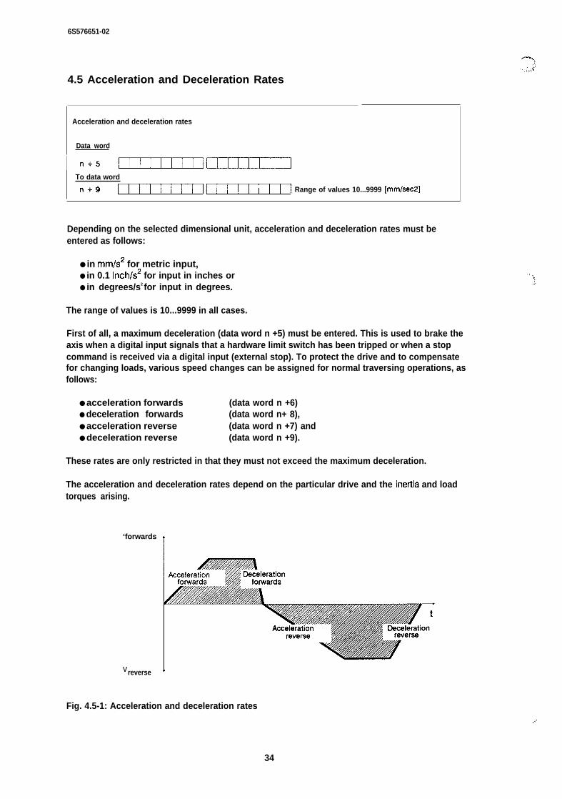
4.5 Acceleration and Deceleration Rates
Acceleration and deceleration rates
Data word
I n+5 uuuul~To data word
n+9 UZIIIZUUEUEEEI Range of values 10...9999 [mm/sec2]
Depending on the selected dimensional unit, acceleration and deceleration rates must beentered as follows:
● in mm/s2 for metric input,● in 0.1 inch/s2 for input in inches or● in degrees/s2 for input in degrees.
The range of values is 10...9999 in all cases.
First of all, a maximum deceleration (data word n +5) must be entered. This is used to brake theaxis when a digital input signals that a hardware limit switch has been tripped or when a stopcommand is received via a digital input (external stop). To protect the drive and to compensatefor changing loads, various speed changes can be assigned for normal traversing operations, asfollows:
● acceleration forwards (data word n +6)● deceleration forwards (data word n+ 8),● acceleration reverse (data word n +7) and● deceleration reverse (data word n +9).
These rates are only restricted in that they must not exceed the maximum deceleration.
The acceleration and deceleration rates depend on the particular drive and the inettia and loadtorques arising.
‘forwards
1
. .. .‘}
vreverse 1
Fig. 4.5-1: Acceleration and deceleration rates
34
.,.,
BS576651-02
., . . 4.6 Controller Parameters
The controller parameters involve the following:
● the gain factor (kv factor) of the position controller,● the maximum following error and● the standstill monitoring.
The IW factor directly influences the position controller. The maximum following error and thestandstill monitoring on the other hand are only used for monitoring the control function.
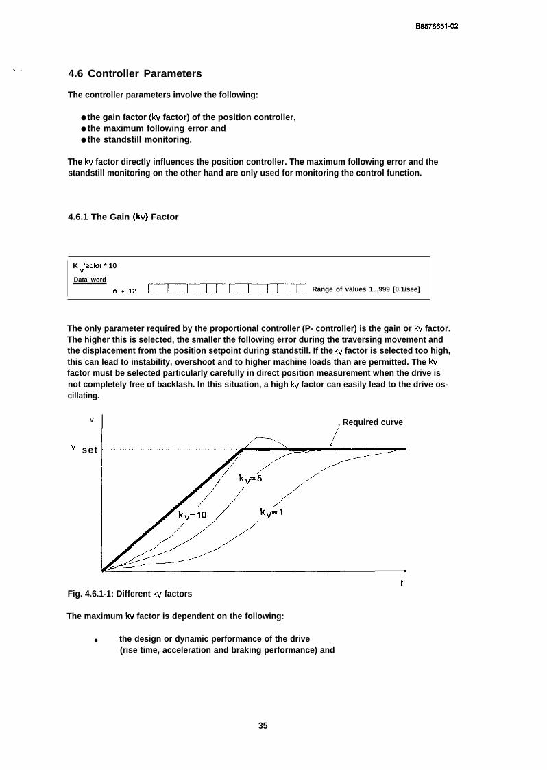
4.6.1 The Gain (kv) Factor
K “factor * 10
Data word
n+12 UJTEUIIUIIEU13 Range of values 1,..999 [0.1/see]
The only parameter required by the proportional controller (P- controller) is the gain or kv factor.The higher this is selected, the smaller the following error during the traversing movement andthe displacement from the position setpoint during standstill. If the IW factor is selected too high,this can lead to instability, overshoot and to higher machine loads than are permitted. The kvfactor must be selected particularly carefully in direct position measurement when the drive isnot completely free of backlash. In this situation, a high IW factor can easily lead to the drive os-cillating.
v
v se t
I , Required curve
tFig. 4.6.1-1: Different kv factors
The maximum W factor is dependent on the following:
● the design or dynamic performance of the drive(rise time, acceleration and braking performance) and
35
B8578851-02
● the quality of the control loop(maximum deviation of the actual position value from the position setpoint; actingtime; control area).
The following range of values applies to the kv factor:
0.1 ...99.9 [l/see]
In practice, a starting value of 16.6/sec has often proved useful for the optimization of the system.
The significance of the IW factor becomes clear when we consider operating the position control-ler at a constant speed. If you traverse at a speed v, a following error xd must occur owing to theP-controller when the drive is correctly set. The following applies for W:
v [mm/min]xd [mm] = --------------------
60. kv [l/see]
Since the speed is specified in mm/min in this case, the following error xd is also in mm. If thespeed is specified in other units, a following error in 0.1 inches or in degrees will result.
With the software package C0M246, the following error can be constantly monitored. You canthen compare whether the displayed value conforms to the value calculated using the formula.
4.6.2 Maximum Following Error
I
Maximum following error
Data word
fl+17 UZIEU13UIEIIIIData word
n + 1 8 ~~
Range of values 0.001...99.999 mm
(at 99M9 the monitoring
is disabled)
The maximum following error is the maximum difference between the position setpoint andactual position value permissible during the traversing operation.
36
BS576651-02
Ad
Position setpoint\\\
‘i
➤
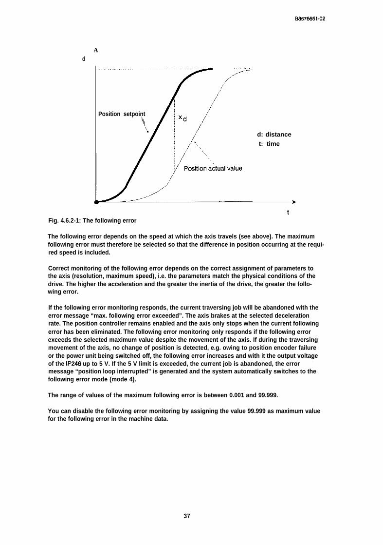
d: distancet: time
tFig. 4.6.2-1: The following error
The following error depends on the speed at which the axis travels (see above). The maximumfollowing error must therefore be selected so that the difference in position occurring at the requi-red speed is included.
Correct monitoring of the following error depends on the correct assignment of parameters tothe axis (resolution, maximum speed), i.e. the parameters match the physical conditions of thedrive. The higher the acceleration and the greater the inertia of the drive, the greater the follo-wing error.
If the following error monitoring responds, the current traversing job will be abandoned with theerror message “max. following error exceeded”. The axis brakes at the selected decelerationrate. The position controller remains enabled and the axis only stops when the current followingerror has been eliminated. The following error monitoring only responds if the following errorexceeds the selected maximum value despite the movement of the axis. If during the traversingmovement of the axis, no change of position is detected, e.g. owing to position encoder failureor the power unit being switched off, the following error increases and with it the output voltageof the IP246 up to 5 V. If the 5 V limit is exceeded, the current job is abandoned, the errormessage “position loop interrupted” is generated and the system automatically switches to thefollowing error mode (mode 4).
The range of values of the maximum following error is between 0.001 and 99.999.
You can disable the following error monitoring by assigning the value 99.999 as maximum valuefor the following error in the machine data.
37
66576651-02
4.6.3 Standstill Monitoring
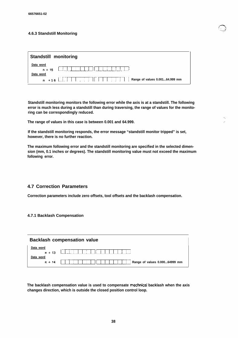
Standstill monitoring
Data word
n+15 UIIHIIIUZIIIILData word
n + 1 6 ~~Range of values 0.001...64.999 mm
Standstill monitoring monitors the following error while the axis is at a standstill. The followingerror is much less during a standstill than during traversing, the range of values for the monito-ring can be correspondingly reduced.
The range of values in this case is between 0.001 and 64.999.
If the standstill monitoring responds, the error message “standstill monitor tripped” is set,however, there is no further reaction.
The maximum following error and the standstill monitoring are specified in the selected dimen-sion (mm, 0.1 inches or degrees). The standstill monitoring value must not exceed the maximumfollowing error.
4.7 Correction Parameters
Correction parameters include zero offsets, tool offsets and the backlash compensation.
4.7.1 Backlash Compensation
Backlash compensation value IData word
n+ls CEIIUEUUIEUEEIData word
n+14 UIIUIIIUUUIII Range of values 0.000...64999 mm
“-,
,;
The backlash compensation value is used to compensate mechnical backlash when the axischanges direction, which is outside the closed position control loop.
38
BS576651-02
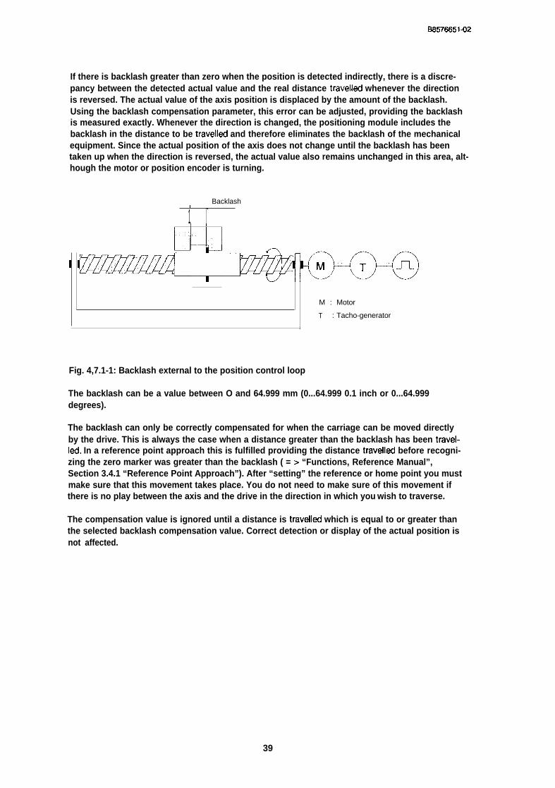
If there is backlash greater than zero when the position is detected indirectly, there is a discre-pancy between the detected actual value and the real distance travelled whenever the directionis reversed. The actual value of the axis position is displaced by the amount of the backlash.Using the backlash compensation parameter, this error can be adjusted, providing the backlashis measured exactly. Whenever the direction is changed, the positioning module includes thebacklash in the distance to be travelled and therefore eliminates the backlash of the mechanicalequipment. Since the actual position of the axis does not change until the backlash has beentaken up when the direction is reversed, the actual value also remains unchanged in this area, alt-hough the motor or position encoder is turning.
Backlash(
1 11
II
M : Motor
T : Tacho-generator
1
Fig. 4,7.1-1: Backlash external to the position control loop
The backlash can be a value between O and 64.999 mm (0...64.999 0.1 inch or 0...64.999degrees).
The backlash can only be correctly compensated for when the carriage can be moved directlyby the drive. This is always the case when a distance greater than the backlash has been travel-Ied. In a reference point approach this is fulfilled providing the distance travelled before recogni-zing the zero marker was greater than the backlash ( = > “Functions, Reference Manual”,Section 3.4.1 “Reference Point Approach”). After “setting” the reference or home point you mustmake sure that this movement takes place. You do not need to make sure of this movement ifthere is no play between the axis and the drive in the direction in which you wish to traverse.
The compensation value is ignored until a distance is travelled which is equal to or greater thanthe selected backlash compensation value. Correct detection or display of the actual position isnot affected.
39
06576651-02
.. ..,,.”
4.7.2 Tool Length Offset
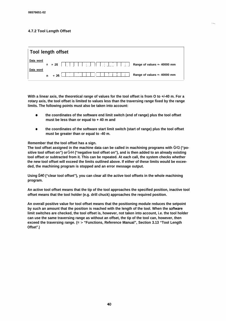
Tool length offset
Data word
n +25 UEUII13CEUEEUI Range of values +- 40000 mm
Data word
n +26 ~~Range of values +- 40000 mm
With a linear axis, the theoretical range of values for the tool offset is from O to +/-40 m. For arotary axis, the tool offset is limited to values less than the traversing range fixed by the rangelimits. The following points must also be taken into account:
● the coordinates of the software end limit switch (end of range) plus the tool offsetmust be less than or equal to + 40 m and
● the coordinates of the software start limit switch (start of range) plus the tool offsetmust be greater than or equal to -40 m.
Remember that the tool offset has a sign.The tool offset assigned in the machine data can be called in machining programs with G43 (“po-sitive tool offset on”) or G44 (“negative tool offset on”), and is then added to an already existingtool offset or subtracted from it. This can be repeated. At each call, the system checks whetherthe new tool offset will exceed the limits outlined above. If either of these limits would be excee-ded, the machining program is stopped and an error message output.
Using G40 (“clear tool offset”), you can clear all the active tool offsets in the whole machiningprogram.
An active tool offset means that the tip of the tool approaches the specified position, inactive tooloffset means that the tool holder (e.g. drill chuck) approaches the required position.
An overall positive value for tool offset means that the positioning module reduces the setpointby such an amount that the position is reached with the length of the tool. When the sollwarelimit switches are checked, the tool offset is, however, not taken into account, i.e. the tool holdercan use the same traversing range as without an offset, the tip of the tool can, however, thenexceed the traversing range. (= > “Functions, Reference Manual”, Section 3.13 “TooI LengthOffset”.)
40
68576851-02
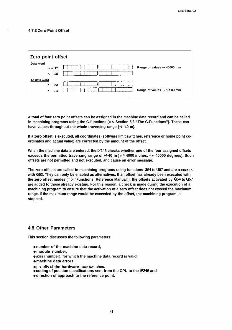
... , 4.7.3 Zero Point Offset
Zero point offsetData word
n+27 UEEUEEICUUIIII
To data word
n+ss UIIIUIICCUEUII
n+sd UIEUEIIUEUEUI
Range of values +- 40000 mm
Range of values +- 40GO0 mm
A total of four zero point offsets can be assigned in the machine data record and can be calledin machining programs using the G-functions (= > Section 5.6 “The G-Functions”). These canhave values throughout the whole traversing range (+/- 40 m).
If a zero offset is executed, all coordinates (software limit switches, reference or home point co-ordinates and actual value) are corrected by the amount of the offset.
When the machine data are entered, the IP246 checks whether one of the four assigned offsetsexceeds the permitted traversing range of +/-40 m (+/- 4000 inches, +/- 40000 degrees). Suchoffsets are not permitted and not executed, and cause an error message.
The zero offsets are called in machining programs using functions G54 to G57 and are cancelledwith G53. They can only be enabled as alternatives. If an offset has already been executed withthe zero offset modes (= > “Functions, Reference Manual”), the offsets activated by G54 to G57are added to those already existing. For this reason, a check is made during the execution of amachining program to ensure that the activation of a zero offset does not exceed the maximumrange. If the maximum range would be exceeded by the offset, the machining program isstopped.
4.8 Other Parameters
This section discusses the following parameters:
● number of the machine data record,● module number,● axis (number), for which the machine data record is valid,● machine data errors,● PolaritY of the hardware limit Swritches,● coding of position specifications sent from the CPU to the IP246 and● direction of approach to the reference point.
41
B6576651-02
. . ... . . .. ,
Number of the machine data recordData word
n+2 1011 10Iqo1011 10 ICEEnrEn ~n9eofvalu’=’o=
A DB number from 0...255 can be assigned to a machine data record.
Each positioning module can control two axes, with the fixed designation axis 1 and axis 2. Eachmodule is also assigned a module number between O and 99. This information uniquely identifiesan axis. To be able to assign a machine data record to an axis, this must contain both values.
I Module number/axis I
Each machine data record also contains an error variable. Some of the possible input errors
Machine data errorsData word
n+ 4 EIITHIIUIITEUI Range of values O...max. 255
made when generating the machine data record on the programmer are detected by the softwa-re package C0M246. Further checks are made when the machine data are entered into the posi-tioning module by its firmware. If an error is detected, the corresponding error number is writtento the error variable of the machine data record and the error message “error in machine data” isoutput.
The absolute version of the IP246 can indicate the current actual position value after removingthe module without recalibrating it ( = > “Functions, Reference Manual”, Section 3.4.3 “SpecialFeatures when using Absolute Position Encoders”) if a machine data record with a valid homepoint has been transferred to the axis. This requires two additional values in the machine datarecord (data word 61 and data word 62/63). These values cannot be displayed with COM246and can therefore not be edited. Data word 61 indicates whether the home point entered in thedata record is “valid” (“l”) or “invalid” (“O”).
,,. !
42
BS57665142
,. . . . 4.8.1 The Polarity of the Hardware Limit Switches
I
Polarity HW limit switch
Data word ~? ~6 25 24 23 22 21 20
n+= CEIIInm I I I I I I I J’+o positive (normally open)
fl+sa cmIIrm I I I I I I I 1+1 negative (normally closed)
In addition to the software limit switches, two hardware limit switches are also evaluated viadigital inputs. These should normally be after the software limit switches. If they are in front of thesoftware limit switches, they limit the traversing range instead of the software limit switches.
These hardware limit switches can either both be stipulated as normally closed (“l”) or both asnormally open (“O”) using the parameter “polarity HW limit switch”. A normally open switch gene-rates a positive edge at the corresponding digital input and is therefore high-active. A normallyclosed switch generates a negative edge and is therefore low-active. For safety reasons, youshould use normally closed switches as the hardware limit switches. The IP246 then recognizesa wire break during operation as the tripping of a limit switch and stops the movement. The trip-ping of a hardware limit switch is, however, only recognized when the axis is moving or shouldmove in the direction of the activated switch.
If machine data are transferred to the module, the assignment of parameters for the hardwarelimit switches is checked. The IP246 can only detect incorrect parameter assignment whenneither of the hardware limit switches is active when the machine data are input. If a rotary axishas been selected, the digital inputs for hardware limit switches are also evaluated. If, however,no limit switches are connected, the polarity must be set to “normally open” (pos “O”).
4.8.2 Target Information from PC is BCD-Coded
I PC BCD-coded iData word 27 Ze 25 24 23 22 21 20
n + 52 [111111111111111 1 ] + Target information from
PC is BCD-coded
n -t 52 I ]0 I - Target information from
PC is binary coded !
Using the parameter “PC BCD-coded” you can inform the module whether target information,tool offsets and zero offsets sent by the PC to the IP246 are in binary or BCD format.
Remember that each position, each tool offset and each zero offset of the corresponding axis isinterpreted in the selected format by the IP246 and this selected format will be used until a diffe-rent coding is specified in the machine data record.
43
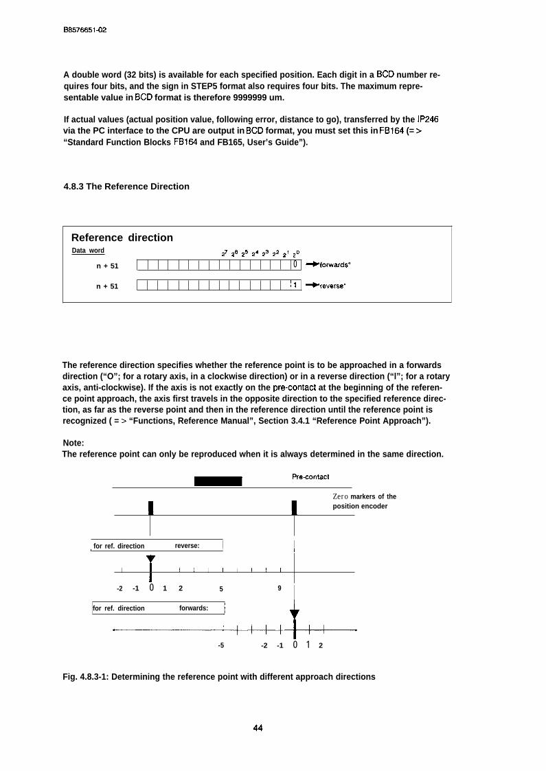
BS576651-02
A double word (32 bits) is available for each specified position. Each digit in a BCD number re-quires four bits, and the sign in STEP5 format also requires four bits. The maximum repre-sentable value in BCD format is therefore 9999999 um.
If actual values (actual position value, following error, distance to go), transferred by the IP246via the PC interface to the CPU are output in BCD format, you must set this in FB164 (= >“Standard Function Blocks FB164 and FB165, User’s Guide”).
4.8.3 The Reference Direction
Reference directionData word ~1 *6 *5 24 23 *2 ~1 20
n + 51 0 ~forwards”
n + 51 \l -reverse”
The reference direction specifies whether the reference point is to be approached in a forwardsdirection (“O”; for a rotary axis, in a clockwise direction) or in a reverse direction (“l”; for a rotaryaxis, anti-clockwise). If the axis is not exactly on the pre-contact at the beginning of the referen-ce point approach, the axis first travels in the opposite direction to the specified reference direc-tion, as far as the reverse point and then in the reference direction until the reference point isrecognized ( = > “Functions, Reference Manual”, Section 3.4.1 “Reference Point Approach”).
Note:The reference point can only be reproduced when it is always determined in the same direction.
Pre-contact
Zero markers of the
Iposition encoder
I
I for ref. direction reverse: I I\ 1 I
I I I I I 1 I I I 1 I
I-2 -1 0 1 2 5 9 I
for ref. direction forwards: ~ 4
-5 -2 -1 0 1 2
Fig. 4.8.3-1: Determining the reference point with different approach directions
44

BS57E6514)2
. .5 Machining Programs and their Structure
5.1 General
A machining program is a connected series of traversing jobs, dwell times and offsets. Machi-ning programs comprise individual statements. Each statement is itself a complete and feasiblejob for the positioning module. The machining programs can be stored in the RAM of the positio-ning module, from there they are executed either as a series of statements or in the single state-ment mode. The machining programs accepted by the positioning module generally correspondin terms of their structure to a subset of the representation described in DIN 66025. Only thissubset is explained here. C0M246 provides you with user-friendly support when generating amachining program. Deviations from the permitted subset of DIN 66025 are signalled immediate-ly when generating the program.
Note:
. Machining programs are independent of the axes. A machining program can be executedsimultaneously both on axis 1 and axis 2. It is of little importance whether the particularaxis is linear or rotary.
. Machining programs do not include dimensions. Position information and speeds arealways interpreted in the unit assigned to the axis in the machine data record.
The programs consist of a sequence of ASCII characters. The following restrictions apply:
● a maximum total of 10000 ASCII characters can be stored on the IP246e these can be divided into 255 programs● a maximum of 1023 ASCII characters are permitted per program.
Repeat loops and subroutines are possible in the programs.
If a statement is inserted in an existing machining program using the machining program editorof COM246, or if a statement is appended to a program, 50 characters are resetved for this state-ment. If the maximum length of a machining program would be exceeded by this addition,COM246 generates an error message.
A machining program generated with COM246 cannot be loaded in the CPU directly. If you wishto store a machining program in the CPU, you must transfer the machining program of the IP246to an S5 data block on the CPU. The machining program number is entered in the machiningprogram header. Program numbers 0...255 are permitted.
45

B6576651-02
A machining program is structured as follows:
;e=s. ;, . . . ..
Y033 Test program. }
Program header
NI G25 X300.000 F2000 MIO
N2 G04 F1OOO
~~ŠŒ }
Statements of the machining programN3 X200.250 F1OOO M30
N4 GOO X120.000 M40
N5 M02)-
Final statement: program end
‘-”%.},
;-,.
Fig. 5.1 -1: Structure of a machining program with program number 33
The machining program always has a program header and a final statement. The final statementhas the special identifier M02 at the end. The length of individual statements can vary.
5.2 Program Header
The program header is generated automatically by COM246 when the machining program iscreated at the PG.
The header includes the following:
6 The program identifier:
‘A = main programL = subroutine,
● The program number (maximum three characters) = DB number of the data block
● A text with a maximum of 58 characters (selected as required by the user)
● < LF > (line feed) to complete the header
Example:0/05 this is a main program in DB5 c LF>L12 this is a subroutine in DB12 c LF>
The difference between main programs and subroutines is simply of documentary interest, themodule does not distinguish between them, so that a program can be used both as a mainprogram and a subroutine. Recursive or reciprocal program calls are, however, notpermitted.
.,
46
BS571X514)2
.>, 5.3 Program Statements
A statement in a machining program consists of a series of functions which have a fixed orderand must be separated by at least one blank. Each statement must be completed by a line feed(c LF>). The length of a statement is limited to 50 characters, including -=LF>. Blanks beforeand after the line feed are not necessary, but permitted. Blank lines following a line feed are inclu-ded in the length of the next statement.
The following functions are available:
● N-function statement type and statement number● L-function subroutine call● G-function preparation of traversing conditions● X-function target function● F-function speed, time, loop execution● M-function auxiliary function
It is not necessary to include all functions in a statement, however, they must not occur morethan once in a statement. All the functions used must be in the order listed here. Some functionsmust be the last in a statement or can only be followed by certain other functions, cf. Fig. 5.10-1“Syntax diagram” on page 64.
The N-function in a statement and the completion by < LF > are obligatory, as is the functionM02 in the final statement of the machining program. No funther statement can follow this.
Example7.9 program exampleN1O G74 M1O approach the already known reference point
Ml O is output at the start of the statementN20 G24 F5 beginning of a repetition loop with five repetitionsN30 L36 call subroutine 36N40 X50 F2000 approach point 50 mm at 2000 mm/min *N50 G20 end of the repetition loopN60 M02 final statement, program end
*The example applies to the presetting “dimensional unit mm” and “target specification absolu-te”.
5.4 The N-function
The N-function is the first function in a statement and specifies the number of the statement. Thisfunction is obligatory and consists of the character ‘N’, followed by a maximum three digitnumber between O and 999.
The statement numbers can be entered in any order, and can be used more than once in a ma-chining program.
The execution of the statements is always in the order in which they are entered inthe machining program.
47
BS576651-02
All statements are treated as “normal statements” according to DIN 66025. The statement identi-fiers “/N’ I for skippable statement and “:N’I for main statement are permitted, are, however, of nosignificance.
5.5 The L-Function
A different program can be called as a subroutine in a program statement. This call must followthe N-function immediately. The function consists of the character ‘L’ followed by the machiningprogram number of the program to be called.
No further functions can follow the L-function and the statement is completed with c LF >.
Examples:N1O L123 < LF> call subroutine 123N20 L5 c LF> call subroutine 5
Subroutines can be nested. The nesting of loops and subroutines must not exceed a nestingdepth of 5.
5.6 The G-Functions
A G-function can follow an N-function. It is identified by the letter ‘G’, followed by a two digitnumber. Only one G-function is permitted in a statement. Only the following G-functions are per-mitted:
● GOO: rapid traverseo G04: dwell time● G1O: flying change● G20: loop end● G24: loop start● G25: approach target by shortest route (*)● G26: approach target in clockwise direction (*)● G27: approach target in anti-clockwise direction (*)● G40: clear tool offset● G43: positive tool offset on● G44: negative tool offset on● G53: clear offsets● G54: offset 1 on● G55: offset 2 on● G56: offset 3 on● G57: offset 4 on● G70: dimensions in 0.1 inches (*)● G71: dimensions in mm (*)● G74: reference point approach● G90: position specifications absolute (*)● G91: position specifications incremental (*)
(*) = iatching (retentive) functions
48
6S576651-02
At the beginning of a program the following G-functions are automatically active:
● G25: approach targets by the shortest route● G90: dimensions absolute
If the machine data of the axis on which the machining program is to be executed are in mm,G71 (dimensions in mm) is also the default. If the machine data are in 0.1 inches, then G70 (di-mensions in 0.1 inches) is the default.
If degrees are selected, neither G70 nor G71 are defaults, since it is not possible to change thedimensional unit.
With the G-functions implemented on the IP246, the following preparatory conditions, offsets orswitchovers can be executed.
5.6.1 -GOO: Rapid Traverse
The target position programmed in this statement is approached at the maximum speed (seemachine data). Specifying the speed using the F-function is then not permitted.
Example:N50 GOO X1OOO M23 output the auxiliary function M23 at the beginning of the
statement..At maximum speed to target point 1000.
5.6.2 -Go4: Dwell Time
A dwell time is executed in this statement. The duration can be set using the F-function in unitsof 100 msec.
Example:N38 G04 F1O M34 output of auxiliary function M34 at the beginning of the
statement.Wait for 10 ● 100 msec = 1 sec.
5.6.3 -G1O: Flying Change
The statement following the statement containing GI O is carried out without stopping the axis.The following can therefore be achieved:
o speed changes during a traversing movement (example 1 ) or● changing the M-function during a continuous traversing movement (example 2).
Example 1: initial point at program start x = O
N30 (G1O) X50 F1OOO M30N32 (G1O) X1OO F500 M31N34 X150 F1OOO M32N36 M02
to target point 50 mm at 1000 mm/minto target point 100 mm at 500 mm/minto target point 150 mm at 1000 mm/minfinai statementiprogram end
49
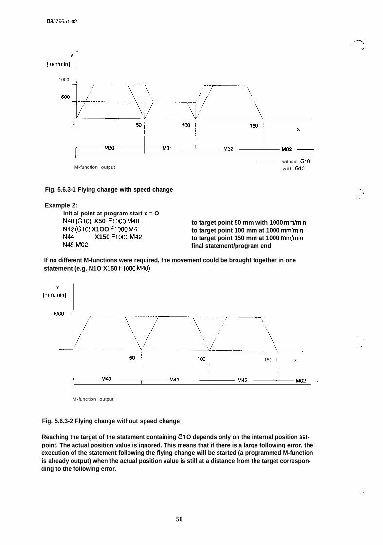
BS576651-02
v
[mm/min]I
1000 i.
500
1
1 II(
t
M30 M31 1, M32 M02 —
without G1OM-function output with G1O
Fig. 5.6.3-1 Flying change with speed change
Example 2:Initial point at program start x = ON40 (G1O) X50 F1OOO M40 to target point 50 mm with 1000 mm/minN42 (G1O) X1OO F1OOO M41 to target point 100 mm at 1000 mm/minN44 X150 F1OOO M42 to target point 150 mm at 1000 mm/minN45 M02 final statement/program end
If no different M-functions were required, the movement could be brought together in onestatement (e.g. N1O X150 F1OOO M40).
v[mm/min]
50{ 1(3CI 15( II
xI
t ,! i !
I
tM40 r M41 —
I M42 J M02–-
M-function output
Fig. 5.6.3-2 Flying change without speed change
y%,,.7
Reaching the target of the statement containing G1 O depends only on the internal position set-point. The actual position value is ignored. This means that if there is a large following error, theexecution of the statement following the flying change will be started (a programmed M-functionis already output) when the actual position value is still at a distance from the target correspon-ding to the following error.
50
B8578851-02
. Special features of “flying change”
The “position reached” message (= > Section 6 “Axis Attributes”), is not set on completion of astatement with G1 O.
Statements connected by the flying change are treated as one statement in the mode BA9 “auto-matic single statement” (execution of the machining program statement by statement). Thismeans that there is no stoppage between these statements. If G1O and an MOO (“programmedhalt”) are programmed in one statement, MOO has priority.
A “flying change” cannot be executed under the following conditions. The program is thenstopped with the error message “statement not allowed after flying change”:
9
●
●
●
●
●
●
when the statement following the flying change specifies the opposite direction,when the statement following the flying change contains a dwell time,when the statement following the flying change only contains an M02,when the traversing distance following the flying change is shorter than the brakingdistance of the previous statement,when the traversing distance of the statement containing G1 O is so short that the axiswill not reach the required final speed,when the statement following the execution of the statement containing G1 O couldnot be completely interpreted orwhen the statement following the flying change containsa switchover,tool offset orzero offset.
5.6.4 LOOPS
Loops can be nested within each other. Subroutines containing further loops can be called inloops. The nesting depth for subroutines and loops must not exceed a total value of 5. Closed(endless) loops can only be programmed at the highest level. A closed-loop cannot therefore beincluded in a program called with an L-function.
- G20: loop end
A statement containing G20 is the end of a repetitive loop and must not contain any otherfunctions.
ExampleN80 G20 end of the repetitive loop.
- G24: loop start
A statement containing G24 is the start of a loop. The number of repetitions is specified by the F-Functions. FO means a closed-loop. The statement must not contain any further functions, inclu-ding M-functions.
51

BS576651-02
ExampleN1O G24 FON20 G74N30 G24 F5N40 L30N50 G04 F1ON60 L30N70 G20N80 G20N90 M02
start of a closed-loopapproach to reference pointstart of a loop with 5 repetitionscall subroutine 30wait one secondrecall subroutine 30end of the inner loopend of the closed-loopfinal statement/program end
5.6.5 Direction of Approach to the Target Point with a Rotary Axis
With a rotary axis, absolute target points can either be approached by the shortest route (G25)or clockwise (G26) or anti-clockwise (G27). If machining programs containing these G- functionsare executed on a linear axis, they are ignored.
-G25: approach target by shortest route (default at program call)
With a rotary axis, the function G25 means that all absolute targets are approached by the shor-test route. The module itself determines the direction of approach. If the distance to the target isthe same both in a clockwise and anti-clockwise direction, the clockwise direction will always beselected ( = preferred direction). When deciding the direction of approach, backlash compensa-tion is ignored.
Example:A backlash compensation of 60 degrees was selected in the machine data.The target (180 degrees) is to be approached by the shortest route (G25). The currentposition is O degrees.Ignoring the reversal backlash, the traversing distance is the same in both directions.The traversing direction of the previous job was anti-clockwise.
= > The distance travelled is longer owing to the backlash (180 degrees + 60 degrees). The tra-versing movement therefore takes longer in the preferred direction than in the opposite direction.
0/360 degrees 0/360 dqrees 0/260 degrees
Actual valuef
270
,/.
Actual valuet
— B a c k l a s h
270(
/
+
27o
I 180 ‘ 180 \ 180Eack18.sh —
Actuat value
Last traversing movement Traversing movement Trawrsing mwement
taking up the backlash of further 160 degrws
actual value still at 0/380 degrees actual value at 1.90 degrees
Fig. 5.6.5-1: Reversal backlash with a rotary axis
52
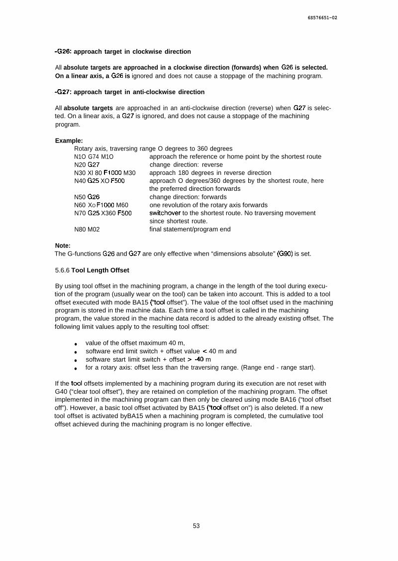
6S576651-02
-G26: approach target in clockwise direction
All absolute targets are approached in a clockwise direction (forwards) when G26 is selected.On a linear axis, a G26 is ignored and does not cause a stoppage of the machining program.
-G27: approach target in anti-clockwise direction
All absolute targets are approached in an anti-clockwise direction (reverse) when G27 is selec-ted. On a linear axis, a G27 is ignored, and does not cause a stoppage of the machiningprogram.
Example:Rotary axis, traversing range O degrees to 360 degreesN1O G74 M1O approach the reference or home point by the shortest routeN20 G27 change direction: reverseN30 Xl 80 F1OOO M30 approach 180 degrees in reverse directionN40 G25 XO F500 approach O degrees/360 degrees by the shortest route, here
the preferred direction forwardsN50 G26 change direction: forwardsN60 XO F1OOO M60 one revolution of the rotary axis forwardsN70 G25 X360 F500 switchover to the shortest route. No traversing movement
since shortest route.N80 M02 final statement/program end
Note:The G-functions G26 and G27 are only effective when “dimensions absolute” (G90) is set.
5.6.6 Tool Length Offset
By using tool offset in the machining program, a change in the length of the tool during execu-tion of the program (usually wear on the tool) can be taken into account. This is added to a tooloffset executed with mode BA15 (’tool offset”). The value of the tool offset used in the machiningprogram is stored in the machine data. Each time a tool offset is called in the machiningprogram, the value stored in the machine data record is added to the already existing offset. Thefollowing limit values apply to the resulting tool offset:
● value of the offset maximum 40 m,● software end limit switch + offset value e 40 m and● software start limit switch + offset >-40 m● for a rotary axis: offset less than the traversing range. (Range end - range start).
If the tool offsets implemented by a machining program during its execution are not reset withG40 (“clear tool offset”), they are retained on completion of the machining program. The offsetimplemented in the machining program can then only be cleared using mode BA16 (“tool offsetoff”). However, a basic tool offset activated by BA15 (’tool offset on”) is also deleted. If a newtool offset is activated byBA15 when a machining program is completed, the cumulative tooloffset achieved during the machining program is no longer effective.
53
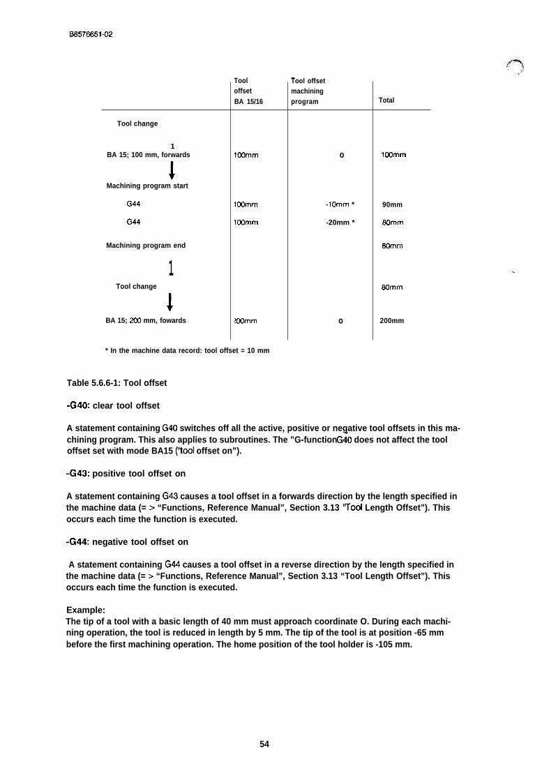
B8576J351-02
—
Tool change
1BA 15; 100 mm, forwards
IMachining program start
G44
(344
Machining program end
1Tool change
I
BA 15; 2(20 mm, fowards
TooloffsetBA 15/16
IOOmm
IOOmm
IOOmm
?OOmm
Tool offsetmachiningprogram
o
-lOmm *
-20mm *
o
Total
IOOmm
90mm
60mm
60mm
.,
60mm
200mm
* In the machine data record: tool offset = 10 mm
Table 5.6.6-1: Tool offset
-G40: clear tool offset
A statement containing G40 switches off all the active, positive or negative tool offsets in this ma-chining program. This also applies to subroutines. The ”G-function G~O does not affect the tooloffset set with mode BA15 (’tool offset on”).
-G43: positive tool offset on
A statement containing G43 causes a tool offset in a forwards direction by the length specified inthe machine data (= > “Functions, Reference Manual”, Section 3.13 ‘Tool Length Offset”). Thisoccurs each time the function is executed.
-G44: negative tool offset on
A statement containing G44 causes a tool offset in a reverse direction by the length specified inthe machine data (= > “Functions, Reference Manual”, Section 3.13 “Tool Length Offset”). Thisoccurs each time the function is executed.
Example:The tip of a tool with a basic length of 40 mm must approach coordinate O. During each machi-ning operation, the tool is reduced in length by 5 mm. The tip of the tool is at position -65 mmbefore the first machining operation. The home position of the tool holder is -105 mm.
54
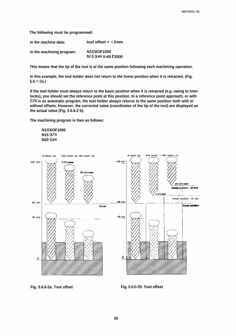
SS576651-02
The following must be programmed:
in the machine data: tool offset = +5mm
in the machining program: N1OXOF1000N15 G44 X-65 F2000
This means that the tip of the tool is at the same position following each machining operation.
In this example, the tool holder does not return to the home position when it is retracted. (Fig.5.6.l-2a.)
If the tool holder must always return to the basic position when it is retracted (e.g. owing to inter-locks), you should set the reference point at this position. In a reference point approach, or withG74 in an automatic program, the tool holder always returns to the same position both with orwithout offsets. However, the corrected value (coordinates of the tip of the tool) are displayed asthe actual value (Fig. 5.6.6-2 b).
The machining program is then as follows:
N1OXOF1000N15 G74N20 G44
1s1 Mach. op. 2nd reach. op. 5th reach. op.
-105 mm.
-65 mm
-40 mm
o—
_!---I----I--------- -5mm wear .105mm
25mmw0ar
.65mm.. —---- . . .Actuai
SD-— ————--— --------- .---. .— -—--- -40 mm.-.
0—
st reach. OP. 2nd reach. OP. 5th reach. OP.
-lili!-- IrIj/ !!?--------25mmwear
Actual posltion:-Kl mm
v5_mm_w.w______ .. J----. . . . . . . .
1 r---------Actual position: -70 mm
.—-..—. . . . . . --- —— —----Actual position
Fig. 5.6.6-2a: Tool offset Fig. 5.6.6-2b: Tool offset
55

BS576651-02
5.6.7 Zero Point Offset
You can program a relative displacement of the coordinate system of your axis during a machi-ning program. This offset is added to offsets executed with mode BA12 (“zero offset absolute”)or BA13 (“zero offset relative”).
In machining programs, only one of the four offset values selected in the machine data can beactivated (G54...G57). if a second zero offset is activated, the first is no longer effective.
The direction of the offset depends on the sign in the machine data.
On completion of a machining program, the offsets activated in the machining program are auto-matically switched off again. This is, however, not the case if the machining program stopsowing to an error message or because of a stop command. In this case, the basic coordinatesystem can only be established again by clearing ail offsets with operating mode BA14 (“clearzero offset”).
Zero offsets executed in a subroutine are not cleared following the return to the main program.They are only reset on completion of the main program.
A zero offset changes the limits of the traversing range, the reference or home point and theactual position value according to the value of the offset. With a positive zero offset, the zeropoint of the coordinate system is displaced in a positive direction, i.e. the individual points on theaxis have a more negative coordinate value. A negative zero offset has the opposite effect.
-G53: clear offsets
G53 deactivates all the zero offsets active in the machining program. Zero offsets activated insubroutines are also cleared. Offsets set with the mode “zero offset absolute or relative” ( = >“Functions, Reference Manual”, Section 3.10 or 3.11 “Zero Offset Absolute or Relative”), are notchanged.
-G54 -G57: offsets I-4 orI
A statement containing one of the G-functions G54-G57 executes a relative zero offset.
● G54 = > zero offset 1● G55 = > zero offset 20 G56 = > zero offset 3 and● G57 = > zero offset 4
The following example (Fig. 5.6-6) contains both types of zero offset. After stipulating the coordi-nate system
\BA 5, run
a relative zero offset 10 mm forwards is executed.
56
0S576651-02
BA 13, +10 mm, forwards I
The actual position value is displaced from O mm to -10 mm. Following this, a traversing move-ment to point O mm is executed.
BA6, O mm, start
Here, machining program 1 is started.
BA8, program 1, start
Subroutine 9 is called in machining program 1. By means of M1O, this program controls the dril-ling of three holes (at O mm, 10 mm and 20 mm). The three coordinates are specified as absolu-te values. Following each execution of subroutine 9, coordinate 40 mm is approached inmachining program 1 and a relative zero offset of 40 mm is executed via G54, an offset of 80 mmby G55 and of 120 mm by G56. The values of the offsets are assigned in the correspondingmachine data record. Subroutine 9 is called a total of three t[mes. Before the end of theprogram, the tool holder is brought to its home position at the reference point by G74. Since theoffsets are still effective, the actual position value is now displayed as -130 mm. At the end of themain program, all the zero offsets activated in the machining program are cleared again. Anoffset of +10 mm remains, which was executed at the beginning with BA13.
Example:
Values in the machine data:
zero offset 1 : 40 mmzero offset 2 : 80 mmzero offset 3 : 120 mm
Machining programs:
‘Al main programN1 L9N2 X40.000 F500N3 G54N4 L9N5 X40.000 F500N6 G55N7 L9N8 X40.000 F500N9 G56N1O G74N11 M02
call subroutine 9to coordinate 40 mm at 500 mm/minzero offset by 40 mmcall subroutine 9to coordinate 40 mm at 500 mm/minzero offset by CKI mm/ G54 no longer effectivecall subroutine 9to coordinate 40 mm at 500 mm/minzero offset by 120 mm/ G55 no longer effectiveapproach reference pointprogram end
L9 subroutineN2 G04 F50 M1O wait 5 sacN3 X1O F1OO to coordinate 10 mm at 100 mm/minN4 G04 F50 M1O wait 5 secN5 X20 F1OO to coordinate 20 mm at 100 mm/minN6 G04 F50 M1O wait 5 secN7 M02 program end
57
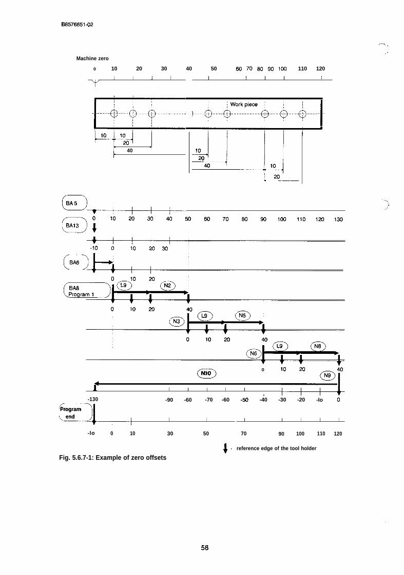
B6576651-02
...-+, <.,,
Machine zero
o 10 20 30 40 50 60 70 60 90 100 110 120
m
I I I IY
-m-’----&&&--”-”-”-
W i[
40 1
I I I I I [ I
wQ-----
1
aN1Oo
P, ;3
I I i I I
-130 -90 -60 -70 -60
cl,
Programend I I
-lo 0 10 30 50
!.
Fig. 5.6.7-1: Example of zero offsets
-50 -40 -30 -20 -lo 0
I I I I I
70 90 100 110 120
reference edge of the tool holder
. .
6S576651-02
5.6.8 Dimensional Units in Machining Programs
The IP246 positioning module interprets machining programs in ttw dkmwtiional unit specified inthe machine data, i.e.:
● machine data in 0.1 inches = > G70 defauit● machine data in mm = > G71 defauits machine data in degrees = >G70 and G71 disabled
-G70: dimensions in 0.1 inches
Following the function G70, all further distances are interpreted in 0.1 inches and all furtherspeeds as 0.1 inches/rein.
-G71: dimensions in mm
Following the function G71, all further distances are interpreted in dimensional unit mm and allfurther speeds as dimensional unit mm/min.
5.6.9 -G74: Reference/Home Point Approach
A statement containing G74 moves the carriage or tool holder to the known reference or homepoint at the incremental speed.
No reference point approach for calibration purposes is executed.
The carriage always moves to the physically stipulated reference or home point, regardless ofwhether the reference or home point coordinates have been changed by a zero offset. Followingthe movement, the display of the actual position value takes into account both a zero offset anda tool offset.
Example:reference point coordinate = O mmeffective zero point offset = +5OO mm andeffective tool offset = 20 mm
After G74 is executed, the axis is positioned at the physically specified reference or home point.The tip of the tool juts out 20 mm from this point. -480 mm is indicated as the actual position.
Following G74, only an M-function is permitted in the statement.
59
B8576651-02
5.6.10 Absolute and Relative Dimensions
-G90: position specifications absolute (default at program call)
All target information (X-functions) following the G90 is interpreted as absolute until G91 isentered.
-G91: position specifications relative
All target information (X-functions) after G91 is interpreted as relative until G90 is entered.
5.7 The X-Function
The X-function is the target function of the statement. It consists of the character “X”, followed byan optional sign and a number which specifies a distance in the units mm, 0.1 inches ordegrees. The number consists of five digits and three decimal places,
The maximum range of values is
X-40000 .000..X + 40000.000
Examples:
X50, X50., X-.5, X + 12345 .678,...
If the decimal point is missing, it is assumed to be at the last place in the number.
5.8 The F-Function
The F-function describes one of the following:
● the speed,● a dwell time or● the number of loop repetitions.
It consists of an ‘F’ and a maximum five digit, signless whole number.
● As a speed, it indicates the units mm/min, 0.1 inches/rein or degrees/rein. The range ofvalues is then 10...65000.
● As a dwell time, it specifies a multiple of 100 ms and can have values between 1 and65000.
● If the F-function is interpreted as a number of loop repetitions, the whole range of O to65000 is possible. If O is specified, the loop is repeated continuously.
60
8S576651-02
5.9 The M-Function
The M-function consists of the character ‘M’ and a two digit number. Permitted values are 0...99.The significance of the number is only fixed for M02 and MOO.
An M-function is only output in conjunction with a traversing job (X-function or G74) or adwell time (Go4) to the programmable controller and to the programmer. M-functions stan-ding alone in a statement or alone with switchovers or offsets in a statement are ignored(exception: Moo).
Each M-function is output at the beginning of the execution of a statement (traversing job ordwell time) and remains valid until the next M-function at the start of the next statement (traver-sing job or dwell time) containing an M-function is output.
In the control program, M-functions can be used to trigger user- specific actions, e.g. the swit-ching on and off of plant during the traversing movement of the axis.
If several statements with consecutive different M-functions are programmed with the help of the“flying change” (G1O) for a traversing movement, remember that the M-function change dependson the internal position setpoint which deviates from the actual position value of the axis by thevalue of the following error.
If statements without M-functions are programmed at the beginning of a machining program,M255 is output. This is output until a statement (traversing job or dwell time) containing an M-function is executed. If a machining program does not contain any M-functions except for M02,then M255 will be output during the whole program.
Examples:
N1O G91N15 G24 F3N20 X1OOO F2000 M1ON30 G57N35 X-500 F2000N45 G20N50 G74 M20N60 X500 FIOO M30N65 G26N70 X1OOO F2000 M60N75 M02
M-function not feasible, output M255N-function not allowed, output M255output M1OM-function not feasible, output M1Ooutput M1OM-function not allowedoutput M20output M30M-function not feasible, output M30output M60final statement/program end
Certain special factors apply to M02 and MOO as follows:
M02
M02 means “program end”. Main programs and subroutines are completed with M02. It must bespecified in the final statement of the machining program. Following this, no further statementscan be appended to the machining program. The final statement can simply consist of the N-function and M02. If M02 is specified in a traversing statement, no further M-function can be spe-cified in the statement.
61

BS576651-02
MOO
..--%,,,. >
MOO means “programmed halt. A statement with an MOO has the effect that the next program-med traversing movement (X-function or G74) or dwell time (Go4) is only executed following anenter command. Offsets (e.g. G57 or G43) and switchovers (e.g. G91) following an MOO andbefore a traversing movement or dwell time are, however, executed before the halt.
N1o X1OO F1OOO MOO (! = break point)N20 ! G04 F200 MOO program halt before the dwell timeN30 ! X200 F500 program halt before the traversing movementN40 Xl 00 FIOOO MOON50 G57 ! X200 F500 break point after the zero offset
If MOO “programmed halt” and G1O “flying change” are programmed in onestatement, the programmed halt has priority.
N1O G1O X1OO F500 MOO (! = break point)N20 ! X200 F1OOO separated owing to MOO
MOO can stand alone or alone with an offset or a switchover following the N-function in a state-ment. In this case, MOO acts as if it is programmed in conjunction with a traversing job with tra-versing distance O. This means that several enter commands may be required following a stop tostart the next traversing movement or dwell time.
N1O X1OO F1OOO MOO (! = break point)N20 ! MOON30 G56 ! MOON40 ! X500 F1OOO three enter commands are required from X1OO to X500
If a machining program is to be stopped directly before the M02 (program end), MOO must beprogrammed alone or alone with an offset or switchover after the end function in a statement. Ifin conjunction with a traversing movement or a dwell time only offsets or switchovers follow theMOO or if M02 (program end) follows directly in the next statement, the machining program is nolonger stopped.
N1O X1OO F1OOO MOON20 M02 MOO no longer effective
N1O X1OO F1OOO (! = break point)N20 MOON39 ! M02 MOO is effective
In the mode BA9 (“automatic single statement”) MOO has no further significance, since in thismode each traversing movement and each dwell time is always started by an enter command.The stop does not need to be acknowledged twice.
N1O X1OO F1OOO MOO (! = break point)N1O ! G04 F1O in BA9 only one enter command necessary to continue
processing
Remember, however, that each MOO either alone or alone with an offset or a switchover follo-wing the end function in a statement is handled as a traversing job with a traversing distance ofO. This means that although the MOO in mode 9 is ignored, the traversing job with the traversingdistance O must still be started with an enter command.
62

B8576651-02
Example of execution in mode 9:
N1O X1OO F1OOO (! = break point)N20 ! MOO halt due to BA9. After enter, execution of the
traversing job with traversing distance ON30 G57 ! MOO halt due to BA9. After enter, execution of the
traversing job with traversing distance O
5.10 Programming Restrictions and Syntax Diagram
To generate feasible machining programs, there are several restrictions and relationshipsbetween the functions which are automatically checked by COM246.
●
●
●
●
●
●
●
●
Following an L-function (subroutine call) only the end of the statement is permitted. In theDIN representation, this means that no further entry can be made in this line, in the textrepresentation, only the selection of another statement is possible.
The X-function (target) must follow the function GOO (rapid traverse) directly.
No X-function can follow the function G04 (dwell time), an F-function (time) is required.
No further function can follow G20 (end of loop) in the statement.
An F-function (number of loops) must follow G24 (end of loop). An M-function is notpermitted.
The X-function (target) is not permitted with G74 (reference or home point approach).
If an X-function is programmed without GOO, the F- function (speed) must follow.
Unless an X-function, G04 (dwell time) or G24 (repetition) is programmed, no F-functioncan be used.
The statement syntax is represented in the following diagram.
63
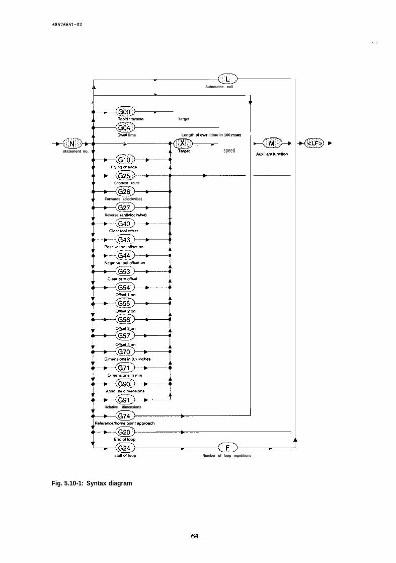
68576651-02
f’--n-n
.,.. >,
. ~A b Subroutine call
L
A
T (i%J r
Rapid traveme Target
G&
Dwell lime Length of till time in 100 msec
v . r
statement no. speed
Shortest route
Forwards (clockwise)
Reverse (anticlc-drwb)
I Relative dimensions
Fig. 5.10-1:
-@9-+Auxlliwyfunctitm
.
f . (G’iJ . (-F-J r
stall of loop Number of loop repetitions
Syntax diagram
64
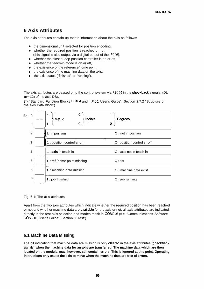
BS576651-02
6 Axis AttributesThe axis attributes contain up-todate information about the axis as follows:
the dimensional unit selected for position encoding,whether the required position is reached or not,(this signal is also output via a digital output of the IP246),whether the closed-loop position controller is on or off,whether the teach-in mode is on or off,the existence of the reference/home point,the existence of the machine data on the axis,the axis status (“finished” or “running”).
The axis attributes are passed onto the control system via FB164 in the checkback signals. (DL(n+ 12) of the axis DB).(=> “Standard Function Blocks FB164 and FB165, User’s Guide”, Section 2.7.2 “Structure ofthe Axis Data Block”).
‘it:~~ ‘JMetfic :],’’ches :]Degrees
-i. t2
H ~~ ~~
I: imposition O : not in position
3 1 : position controller on O: position controller off
4
E ~~ŠŒ
1 : axis in teach-in O : axis not in teach-in
5 1 : ref./home point missing O : set—
6 1 : machine data missing O : machine data exist
7 1 : job finished O : job running
Fig. 6-1: The axis attributes
Apart from the two axis attributes which indicate whether the required position has been reachedor not and whether machine data are availabie for the axis or not, all axis attributes are indicateddirectly in the test axis selection and modes mask in COM246 (= > “Communications SoftwareCOM246, User’s Guide”, Section 8 ‘Test”).
6.1 Machine Data Missing
The bit indicating that machine data are missing is only cieared in the axis attributes (checkbacksignals) when the machine data for an axis are transferred. The machine data which are thenlocated on the module, may, however, still contain errors. This is ignored at this point. Operatinginstructions only cause the axis to move when the machine data are free of errors.
65
6S576S51-02
.“-=%
6.2 Measurement System
In the test mask of COM246, the dimensional unit is displayed beside the actual position value,the following error (or speed) and the distance to go.
6.3 Reference/Home Point Missing
Movements to an absolute target are only possible when a coordinate system has been fixed.The coordinate system is fixed using mode BA5, “reference point approach” or “set referenceor home point”. Following this, the axis attribute indicating the absence of the reference/homepoint is reset.
6.4 Teach-in On
The axis attribute “teach-in on” indicates that the current actual position values of the axis can bestored in a machining program as target information (X-functions). Teach-in operation is activat-ed with mode BA1 O and deactivated with mode BA11.
6.5 Closed-Loop Position Controller On
The axis attribute “position controller on” indicates the status of the position controller. Bothclosed-loop (position controller on) or open-loop (position controller off) operation is possible.Normally, positioning is carried out under closed-loop control. Open-loop operation only occurswith the modes “jog open-loop” and “following error”.
6.6 Axis Status “Finished” or “Running”
. ..
An axis can only be switched from one mode to another in the axis status “finished”. Providingthe job itself is correct, the axis status is changed from “finished” to “running”. In this respect,there is no difference between traversing jobs and jobs which do not lead to a traversing move-ment, e.g. coordinate transformations, drift compensation or data transfer. On completion of thecurrent job, the axis status once changes to the “finished” status. In automatic operation, theaxis status is only set to “finished” on completion of the machining program (see next section).
66
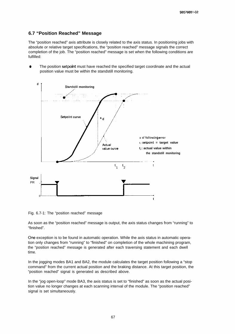
BS576651-02
6.7 “Position Reached” Message
The “position reached” axis attribute is closely related to the axis status. In positioning jobs withabsolute or relative target specifications, the “position reached” message signals the correctcompletion of the job. The “position reached” message is set when the following conditions arefulfilled:
● The position setpoint must have reached the specified target coordinate and the actualposition value must be within the standstill monitoring.
d
IStan~till monitoring
Setpoint curve
X d: fdbWhg error
t l : setpoint = target value
t2 : actual value within
the standstill monitoring
tt1 2
t
SignalPR , v
ot
Fig. 6.7-1: The “position reached” message
As soon as the “position reached” message is output, the axis status changes from “running” to“finished”.
(Me exception is to be found in automatic operation. While the axis status in automatic opera-tion only changes from “running” to “finished” on completion of the whole machining program,the “position reached” message is generated after each traversing statement and each dwelltime.
In the jogging modes BA1 and BA2, the module calculates the target position following a “stopcommand” from the current actual position and the braking distance. At this target position, the“position reached” signal is generated as described above.
In the “jog open-loop” mode BA3, the axis status is set to “finished” as soon as the actual posi-tion value no longer changes at each scanning interval of the module. The “position reached”signal is set simultaneously.
67
6S576651-02
Response to abnormal termination of positioning jobs
If a job with absolute or relative target information is terminated before the conditions for “posi-tion reached” are fulfilled, this axis attribute is not set. The remaining distance to go from thecurrent position setpoint to the actual target point remains indicated and is continuouslyupdated until the start of a new traversing job. It is also updated, if you subsequently activate thefollowing error mode or execute a tool offset. You can now send a relative traversing job with theindicated “distance to go” to the module. The originally required target is then reached.
Timer monitoring when approaching the target
If the position setpoint is already at the target and the actual position value remains outside thestandstill monitoring owing to a load or a drift in the power unit, a waiting time of approximately5 sec is started. If no movement towards the target occurs during this time, the job is terminatedwith the error message “target position not reached” and the axis status set to “finished”. The “po-sition reached” message in this case is not set. Each time there is movement towards the target,the waiting time is reset again. If the axis does not come to a standstill in the “jog open-loop”mode BA3 following a “stop” owing to drift in the power unit or mechanical load, although the po-sition setpoint is already constant, the timer monitoring is also activated. A standstill in open-Ioop operation occurs when the actual position value does not change from scan interval toscan interval.
68
6S576651-02
7 Digital Inputs/Outputs and their Effects
The IP246 has a total of eight digital inputs and four digital outputs (= > “Hardware, instruc-tions”, Section 1.2 “Design”). The digital output signals are high-active and are as follows foreach axis of the IP246:
● the operational signal (FUM) and● the “position reached” message (PR).
Digital inputs are also available for each axis, as follows:
one hardware limit switch to limit the start of the traversing range (ANF),one hardware limit switch to limit the end of the traversing range (END),one precontact for calculation of the reference point andan external start-stop signal (START/STOP).
7.1 The Operational Signal FUM
The digital output FUM is reset after the power to the programmable controller is switched on.After the processor on the IP246 has started up correctly and valid machine data are on themodule, the operational signal for the axis is set to”1”.
Note:
For safety reasons, you must only enable the power unit when the operational signal is setby the IP246. This is achieved by interlocking the enabling of the power unit using theFUM signal. If your power unit does not have an enable input, you must make sure thatthe drive can only be activated when the FUM signal is set to “l”. If this is not the case, it ispossible for the drive to be activated without any control if the 24 V power supply fails dueto an undefined voltage at the analog output of the IP246.
Power unit
I sDeedAnalog signalr setpoint
input
1P 246Operational
, signal FUM
Fig. 7.1-1: Enabling the power unit
69
B8578651-02
The IP246 also has a jumper (disable command output IIBASPI’; = > “Hardware, Instructions”,Section 3.2.1 “Disable Command Output”), which is set when the module is supplied so that alldigital outputs on the module are set to “zero” when the CPU stops. if the digital output is con-nected to the enable input of the power circuitry, the drive is also blocked when the CPU stops.
7.2 The “Position Reached” Message
The “position reached” message is supplied both to the CPU as well as to a digital output. A de-tailed description of the “position reached” message can be found in Section 6 “Axis Attributes”.
7.3 The Digital Inputs for Hardware Limit Switches
The hardware limit switches are evaluated regardless of the axis type. With a rotary axis, hardwa-re limit switches are generally not required, but can be used as an additional safety measure.
The polarity of the two hardware limit switches can be assigned in the machine data record. Youcan select both limit switches as normally closad or both as normally open switches using the“polarity HW limit switch” parameter (= > Section 4.8 “Other Parameters(’).
The hardware limit switches are only detected during a traversing movement or during the follo-wing error mode.
If the module recognizes that a hardware limit switch has tripped, the traversing movement isstopped with the maximum deceleration assigned in the machine data record and the current tra-versing job is terminated. If the tripping of a hardware limit switch is detected in the followingerror mode, only the corresponding error message is generated. The following error moderemains active.
Note:
A hardware limit switch is only detected if the traversing movement is towards it, or whenthe axis is not controlled in the direction in which the axis moves or drifts. If a limit switchresponds, further movement in the direction of the detected limit switch is not possible.This traversing direction is only enabled again
● when the module has detected that the axis has left the hardware limit switch in theopposite direction or
● when a hardware limit switch has been tripped and is tripped again in the oppositedirection.
.,.,,;,
If a hardware limit switch is tripped either manually or by some other external event, movementin this direction is blocked. This direction can be released again by starting a traversing job inthe opposite direction, tripping the hardware limit switch again and then returning it to theneutral position.
70
BS576651-02
. If a blocked direction is not released by the measures described above, it will always be releasedwith the incremental version of the IP246 when the axis reaches the precontact.
After completing the parameter assignment and starting up your system, each axis (linear axis)has two software limit switches. These should always be assigned so that the hardware limit swit-ches can never be reached during operation. Since the IP246 only starts to brake when a softwa-re limit switch is reached, the hardware limit switches should be set far enough away from thesoftware limit switches to allow for the maximum braking distances.
The maximum braking distance can be calculated according to the direction as follows:
Vmax2 [mm2/mif-r2]dbrake IITWTl] = -------------------------------
2. a [mm/s2] .3600
Whereby: dbr.ke is the maximum required braking distance, Vmax is the rnaxhum speed S@Jla-
ted in the machine data and a the deceleration forwards or reverse. The braking distance will bevmax / 8000 longer owing to the reaction times of the IP246.
7.4 External Start/Stop
The digital input “external start/stop” has two functions. A signal change from “O” to “l” serves asan “external stop”, the change from”1” to “O” serves as an “external statl enable”.
External stopDuring the processing of a traversing job, a signal change from “O” to “1” at this digital inputcauses the error message “external stop occurred”, the traversing job and current mode are ter-minated. The axis brakes at the maximum deceleration assigned in the machine data record. Ifthe external stop is received while processing a machining program (automatic mode), the ma-chining program is terminated along with the automatic mode.
Note:In the following error mode (mode 4) “external stop” causes the following error mode tobe terminated and the position controller is enabled again.
External startIf a “l” is set at this digital input before the start of a traversing job, the traversing job is interpre-ted by the IP246 but is not executed. If the job is permissible, you will obtain the message “motorwaiting for external start”. The negative edge of the signai at the digital input causes the traver-sing job to be executed.
Only one single job can be waiting for execution. Other jobs during the waiting time are notallowed. If a further operating instruction if sent to the IP246, the job currently waiting for execu-tion is deleted. A stop command in conjunction with any mode causes error-free termination.The message “motor waiting for external start” is reset. Any command other than “stop” leads tothe error message “inadmissible job”.
71

BS576651-02
The external start enable is also effective in the automatic mode with traversing jobs and dwelltimes. If the signal “1’( is set at this digital input before the start of the automatic mode (mode 8),the machining program starts with the start command and is executed up to the first traversingjob or the first dwell time. The dwell time or traversing job then causes the message “motorwaiting for external start”. The negative edge at the digital input enables the traversing move-ment or dwell time. A further statement within the started machining program cannot be stoppedwith the “external start enable”, since the positive edge of the signal at the digital input is thenevaluated as “external stop”.
If a”1” is set at this digital input before the start of the “automatic single statement” mode (mode9), the start command also leads to the execution of the machining program up to the first pro-grammed traversing job or first dwell time. The “enter command” then causes the message“motor waiting for external start”. The first traversing job or the first dwell time and all the offsetsand switchovers programmed after it are then executed on the negative edge of the signal at thedigital input. If signal “l” is set again at the digital input during the execution of the traversing jobor dwell time, this acts as “external stop”; the machining program is terminated. If, following thecompletion of the traversing movement (“position reached” message set), a”1” is set at thedigital input, the next traversing job or the next dwell time of the automatic program following theenter command will only be triggered by a negative edge at the digital input.
72

BS576651-02
1) Processing of offsets and switchovers
2) Processing the first traversing job and the following offsets and switchovers
3) Processing the second traversing job and the following offsets and switchovers
4) Processing the third traversing job.
Fig. 7.4-1: External start/stop in the automatic single statement mode
73

I
SIEMENS.. ...,,, ,
SIMATIC S5IP246 Positioning Module Incremental
AbsoluteHardware
——.Instructions
6ES5246-4UA31 / -4UA416ES5246-4UB11 / -4UB21
C79000-B8576-C652 -02
B8576652-02
Contents
.. >....,.,.,
1 Technical Description . . . . . . . . . . . . . . . . . . . . . . . . . . . . . . . . . . . . . . . . . . . . . . . . . . . . . 31.1 Application . . . . . . . . . . . . . . . . . . . . . . . . . . . . . . 31.2 Design . . . . . . . . . . . . . . . . . . . . . . . . . . . . . . . . . . . . . . . . . . . . . . . . . . . . . . . . . .. .....4l.3Mode ofOperation . . . . . . . . . . . . . . . . . . . . . . . . . . . . . . . . . . . . . . . . . . . . . . . . . . ........51.4Technical Data . . . . . . . . . . . . . . . . . . . . . . . . . . . . . . . . . . . . . . . . . . . . . . . . . . . . . . . ........8
21nstaflation . . . . . . . . . . . . . . . . . . . . . . . . . . . . . . . . . . . . . . . . . . . . . . . . . . . . . . . . . . . . 102.1 inserting and Removing the Module . . . . . . . . . . . . . . . . . . . . . . . . . . . . . . . . . 102.2 Connecting theSignal Lines . . . . . . . . . . . . . . . . . . . . . . . . . . . . . . . . . . . 10
30peration . . . . . . . . . . . . . . . . . . . . . . . . . . . . . . . . . . . . . . . . . . . . . . . . . . . . . . . . . . . . . 113.1 Position oftheJumpersand Switches . . . . . . . . . . . . . . . . . . . . . . . . . . . . . . . . 113.2 Setting the Module Address ,,, ,,, . . . . . . . . . . . . . . . . . . . . . . . 133.2.1 Disable Command Output . . . . . . . . . . . . . . . . . . . . . . . 143.3 Connecting incremental Position Encoderstothe 246-4UA . . . . . . . . . . . . . . . . . . . . . . . 143.3.1 JumperSettingsand Pin Assignment for5Vlncremental Position Encoders 153.3.2 JumperSettingand Pin Assignment forconnecting 24 Vlncremental Position Encoders 163.3.3 Pin Assignment oftheConnectors for incremental Position Encoders (X4,X5) 173.3.4 Connectable Position Encoders . . . . . . . . . . . . . . . . . . . . . . . . . . . . . . . . . . . . 183.4 ConnectingAbsolute Position Encoderstothe246-4UB . . . . . . . . . . . . . 183.4.1 Pin Assignment ofthe Connectors forAbsolute Position Encoders (X4,X5) . 193.4.2 Connectable Position Encoders . . 193.5 Connecting Motor Power Units ., .,, . . 193.5.1 Pin Assignment ofConnector X6for connecting Motor Power Units . . . . 203.6 Digital inputs/Digital Outputs, . . . . . . . . . . . . . . . . . . . . . . .. .....203.6.1 Pin Assignment ofConnector X7 for Digital inputs/Digital Outputs . . . . . . . . . . . . .......213.7 PGlnterface20 mA . . . . . . . . . . . . . . . . . . . . . . . . . . . . . . . . . . . . . . . . . . . . . . . . . . . . . . . . . 223.7.1 Pin Assignment ofConnector X8 forthe PGlnterface . . . . . . . . . . . . . . . . . . . . . . .. .....233.8 Backplane Cormectorand Memory Cartridge Connector . . . . . . . . . . . . . . . . . . . . . .......233.8.1 Backplane ConnectorXl . . . . . . . . . . . . . . . . . . . . . . . . . . . . . . . . . . . . . . . . . . . . . .......233.8.2 Backplane ConnectorX2 . . . . . . . . . . . . . . . . . . . . . . . . . . . . . . . . . . . . . . . . . 243.8.3 Memory Cartridge Connector X3 . . . . . . . .......24
4Connecting Cab!esand Spare Parts . . . . . . . . . . . . . . . . . . . . . . . . . . . . . . . . . . . . . . . . 25

B8576652-02
1 Technical Description
The IP246 positioning module is available in various versions for connecting the following:
● incremental position encoders and
● absolute position encoders
Both versions are available as two models, one for ventilated and one for non-ventilatedoperation.
6ES5246-4UA31 for incremental position encoders, ventilated6ES5246-4UA41 for incremental position encoders, non-ventilated6ES5246-4UB1 1 for absolute position encoders, ventilated,6ES5246-4UB21 for absolute position encoders, non- ventilated.
The incremental versions of the IP246 (-4UA11 and - 4UA21) provide slightly lessfunctions than those described here.
1.1 Application
The IP246 positioning module is used for closed-loop position control of two independent drives
The main areas of application are as follows:
● auxiliary axes in metal processing machines,
● paper and textile machines,
* handling and loading systems and
● feed devices in transfer lines and assembly lines.
It can be operated in the following SIMATIC S5 programmable controllers (PC) and is inserted inthe slots for communications processors (CP):
SIMATIC-S5 115U with CPU 941,942,943,944,SIMATIC-S5 135U with CPU 922,928,SIMATIC-S5 150U andSIMATIC-S5 155U with CPU 946,947.
It can also be plugged into expansion units with the central controller bus
EU 185 andEU 186
in the CP slots, providing the interface modules AS304/AS314 are used.
3
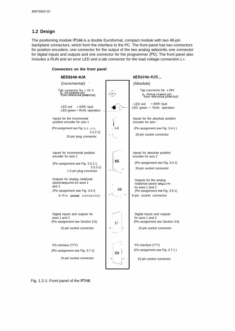
B8576652-02
1.2 Design
The positioning module IP246 is a double Euroformat, compact module with two 48-pinbackplane connectors, which form the interface to the PC. The front panel has two connectorsfor position encoders, one connector for the output of the two analog setpoints, one connectorfor digital inputs and outputs and one connector for the programmer (PG). The front panel alsoincludes a RUN and an error LED and a tab connector for the load voltage connection L+.
Connectors on the front panel
6ES5246-4UA
(Incremental) –
Tab connector for + 24 V,.
(~~~ar~~~~~~[~otential)
LED red = ERR: faultLED green = RUN: operation
Inputs for the incrementalposition encoder for axis 1
(Pin assignment see Fig. 3,2.,1-1,3.3.2-1)
15-pin plug connector
Inputs for incremental positionencoder for axis 2
(Pin assignment see Fig. 3,3.1-1,3.3.2-1)
1 5-pin plug connector
Outputs for analog rotationalspeed setpoints for axes 1and 2(Pin assignment see Fig. 3.5-I)
9 - P i n socket c o n n e c t o r
Digital inputs and outputs foraxes 1 and 2(Pin assignment see Section 3.6)
15-pin socket connector
PG interface (TTY)
(Pin assignment see Fig. 3.7-1)
15-pin socket connector
“a”——
,,-”i! x4
./-’
[;
x5 ~
-- (.. ‘ “
,II X6
+ i,.- ~ .,... ’
-----rX7
-[ .. .
I
..- L ‘‘8 1---4
6ES5246-4UB —(Absolute)
- LED red = ERR: faultLED green = RUN: operation
Inputs for the absolute positionencoder for axis I
(Pin assignment see Fig. 3.4-1 )
26-pin socket connector
Inputs for absolute positionencoder for axis 2
(Pin assignment see Fig. 3.4-1)
26-pin socket connector
Outputs for the analogrotational speed setpointsfor axes 1 and 2(Pin assignment see Fig. 3.5-1)
9-pin socket connector
Digital inputs and outputsfor axes 1 and 2(Pin assignment see Section 3.6)
15-pin socket connector
PG interface (TTY)
(Pin assignment see Fig. 3.7-1 )
15-pin socket connector
Fig. 1.2-1: Front panel of the IP246
B8576652-02
1.3 Mode of Operation
The IP246 decodes and processes the digital pulses from the position measuring systems of twoaxes (actual position values) and continuously outputs the speed setpoints to the actuatorsaccording to the position to be approached.
The module has the following features:
●
●
●
●
●
●
✎
●
●
✎
●
16-bit microprocessor with internal timer and interrupt controller (80186)
16 Kbyte local RAM, backed up by the PC battery
EPROM cartridge interface for loading the firmware
dual-port RAM, backed up by the PC battery
bus interface to the S5 programmable controllers
serial interface to the S5 programmable controllers
two interfaces to incremental or absolute position encoders
eight 24 V digital inputs
four 24 V/120 mA digital outputs
two +/- 10 V analog outputs
two status displays
The operation of the positioning module is controlled by the microprocessor according to theoperating program (firmware) stored in an exchangeable EPROM cartridge.
The parameter assignment, programming and start-up are performed via the PG interface usingthe software package COM 246 ( = > “Communications Software COM 246, User’s Guide’ (). Ifthe data are stored in the CPU, parameter assignment and programming can also be performedvia the PC interface, e.g. when exchanging a module. Providing the module remains pluggedinto a battery-backed PC frame, the machine data and machining programs stored in the RAM ofthe IP246 are retained if a power failure occurs.
Communication with the programmable controller is via the S5 bus interface and a dual-portRAM with a capacity of 2 Kbytes.
To decode the actual position values, incremental position encoders with 5 V differential signalsor 24 V signals can be connected to modules 246 4UA The pulses from the position encodersare evaluated by a 16-bit counter according to the dire~tion, and can be doubled or quadrupled.Cmly one type of position encoder (i.e. 5 V or 24 V) can be connected to any one module.
An absolute position encoder (Gray code or Gray excess X code) with a parallel output signaland a resolution of maximum 20 bits can be connected per axis to the module 246-4UB–. Thecode is converted by the firmware. Both current sourcing and current sinking encoders can beused. A combination of the two types is, however, not possible.

B8576652-02
The position encoders can be supplied with power via the connectors of the module. The voltagefor incremental position encoders can be selected with jumpers.
Setpoints are output via two analog voltage outputs. The firmware selects the reference voltagefor each channel separately to improve the resolution at lower speeds. The output voltage rangeis therefore either O to +/- 1.25 V or O to +/- 10 V in each case with a resolution of 11 bits plussign.
Signals from limit switches and reference point precontacts are received via the digital inputs(per axis 1 reference point precontact and 2 limit switches); there is also an external start/stopinput for each axis. Two digital outputs 24 V/120 mA per axis supply the “position reached” (PR)message and the “operational signal” (FUM). The “FUM” signals must be used as the controllerrelease signals for the power unit.
The analog circuits are supplied via a voltage converter 24 V/+ -15 V, which is connected to the24 V load voltage (L +/L-). The module is reset if the power fails,
Note:
If the 24 V load voltage (L+) is absent, the analog outputs do not assume the value OV, but continue to supply a voltage of 2 to 3 V.
6

B8576652-02
,ncremen,al Position encoderAbsolute
246- 4uA 246- 4uB
H@ ~J#Q wn,.k!!!~ ‘+
Motor power circuitry
II Ill I.... 1 , FUM 1/2Front panel
(5 I x8 X7-”T I X6 I I X19 Ix4 x5 x4 x-
1 ,H ~“--””~
I
“’[’~~x’k~-==”m,
Tx OL- ,- —-- ———. . . .
IOig. act. values ~ig. act. values I -
➤ . . . . . . .
J ‘--;’’’~’---’~ ~-::~
e“,. .,
I I
i h. I ! in”,,!, ~ I ‘‘ I iOn ‘“-l”off a n a l o g -~xI ~“ , +,.,~v
[ ,-- ......–—J L—-–..—
- . . — . . h
I r~~b--fl::,:::f::::::j I~.--;”=;;;:-.:–...t ! ‘A C. L.7-.I
,,. .,,
,:––––;,,
~- ..2—— ——J-
Memory!--c . . .,fi.. -,‘,,,,. .,
. ., –-
i ;.,
2 L . . .
I
~ L–...—I
.,— ——..——
~ ) Lmyes ]
——
‘Wese’ ~ ,.........-...-.–...:—Y––.
RAM ~ I..,... JI
t+-- -- ] ~••
-i... .+ ● -.I IIkp’’’’””i”g J, 77
I
I I ‘>.I
A LBackplane c:gneclOr S5bus X1/X2
,.. -......——+ &--—
L.T X DSn II
R x DSn II—+-+— ----- ‘“”””” ‘—-”-—
,/ \\u‘\ ,,
—-.–.L.. _
I
J : OBO...DB7 ROY)Bo...AOB15
i !
MEM”R 0s1
MEMW
CPKLuBAT
Fig. 1.3-1: Block diagram of the IP246 positioning module
7
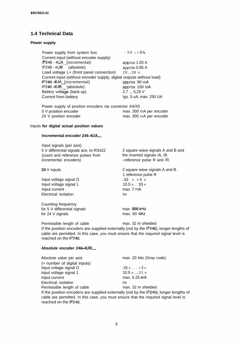
B8576652-02
1.4 Technical Data
Power supply
Power supply from system bus + 5V +/- 570
Current input (without encoder supply)IP246 - 4UA (incremental) approx 1.00 AIP246 - 4UB— (absolute) approx 0.85 ALoad voltage L+ (front panel connection) 20...30 vCurrent input (without encoder supply, digital outputs without load)IP246 -4UA (incremental) approx. 90 mAIP246 -4UB— (absolute) approx. 100 mABattery volt~ge (back-up) 2,7 .,, 5,25 VCurrent from battery typ. 5 uA; max. 250 UA
Power supply of position encoders via connector X4/X55 V position encoder max. 300 mA per encoder24 V position encoder max. 300 mA per encoder
Inputs for digital actual position values
Incremental encoder 246-4UA—
Input signals (per axis)5 V differential signals ace. to RS422 2 square wave signals A and B and(count and reference pulses from the inverted signals /A, /B.incremental encoders) I reference pulse R and /R.
24 V inputs 2 square wave signals A and B.1 reference pulse R
Input voltage signal O -33 v +3 vInput voltage signal 1 10.5 v ,., 33 vInput current max. 7 mAElectrical isolation no
Counting frequencyfor 5 V differential signals max. 500 kHzfor 24 V signals max. 50 kHz
Permissible length of cable max. 32 m shieldedIf the position encoders are supplied externally (not by the IP246), longer lengths ofcable are permitted. In this case, you must ensure that the required signal level isreached on the IP246.
Absolute encoder 246-4UB—
Absolute value per axis max. 20 bits (Gray code)(= number of digital inputs)Input voltage signal O -33 v . . . +3 vinput voltage signal 1 10.5 v ...33 vInput current max. 6.25 mAElectrical isolation noPermissible length of cable max. 32 m shieldedIf the position encoders are supplied externally (not by the IP246), longer lengths ofcable are permitted. In this case, you must ensure that the required signal level isreached on the IP246,
8
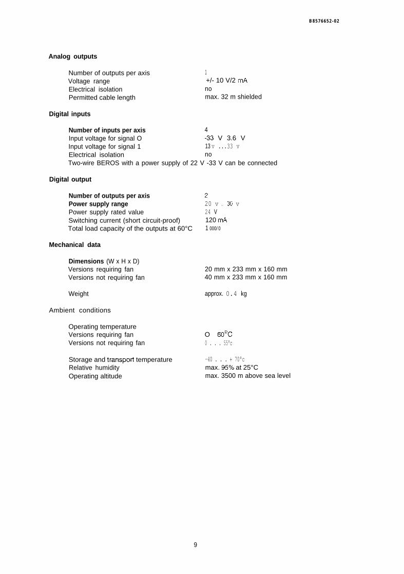
B 8 5 7 6 6 5 2 - 0 2
Analog outputs
Number of outputs per axis 1Voltage range +/- 10 V/2 mAElectrical isolation noPermitted cable length max. 32 m shielded
Digital inputs
Number of inputs per axis 4Input voltage for signal O -33 V 3.6 VInput voltage for signal 1 13 v ...33 vElectrical isolation noTwo-wire BEROS with a power supply of 22 V -33 V can be connected
Digital output
Number of outputs per axisPower supply rangePower supply rated valueSwitching current (short circuit-proof)Total load capacity of the outputs at 60°C
Mechanical data
Dimensions (W x H x D)Versions requiring fanVersions not requiring fan
Weight
Ambient conditions
Operating temperatureVersions requiring fanVersions not requiring fan
Storage and transpoti temperatureRelative humidityOperating altitude
L
20 v ..30 v24 V120 mA1 000/0
20 mm x 233 mm x 160 mm40 mm x 233 mm x 160 mm
approx. 0.4 kg
O 60°C0 . . . 55°c
-40 . . . + 70°cmax. 957. at 25°Cmax. 3500 m above sea level
9
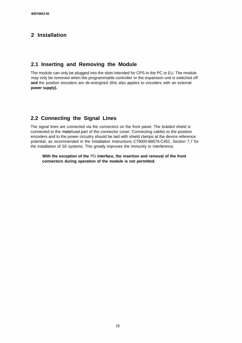
B8576652-02
2 Installation
2.1 Inserting and Removing the Module
The module can only be plugged into the slots intended for CPS in the PC or EU. The modulemay only be removed when the programmable controller or the expansion unit is switched offand the position encoders are de-energized (this also applies to encoders with an externalpower supply).
2.2 Connecting the Signal Lines
The signal lines are connected via the connectors on the front panel. The braided shield isconnected to the metallized part of the connector cover. Connecting cables to the positionencoders and to the power circuitry should be laid with shield clamps at the device referencepotential, as recommended in the Installation Instructions C79000-B8576-C452, Section 7,7 forthe installation of S5 systems, This greatly improves the immunity to interference.
With the exception of the PG interface, the insertion and removal of the frontconnectors during operation of the module is not permitted.
10
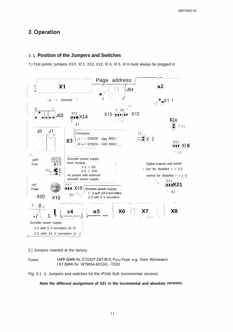
B8576652-02
3.1 Position of the Jumpers and Switches
1.) Test points: jumpers X1O, Xl 1, X12, X13, Xl 4, Xl 5, Xl 6 must always be plugged in
‘-1 Page address ~,.—.—————...—
1 xl ~.T.1..rl.lfj64;,’
x2● LOLL.-..–..;.-.......:
,,0 = pressed “! 2 7 , .2’ ‘O! xl 1lj “““
1.)1 23 “6 .1~m363 3 2 1
Y
● X142.)
’15 wh “3‘–J 1 ,) Xlo
X3
~-–..~ Firmware :
~ JI = > S7920() . G62 A901/
; J3 = > S79200 - G62 A9021—
23 2 1I$OZ Xl 6“ 1,)
,
I.-..
IAFF %
Fuse
d
2.) ● ;
1<
Encoder power supplyfrom module I
1-2 = 5V2-3 = 24V 1
no jumper with external
Digital outputs with BASP
! can be disabled = > 2-3
~ cannot be disabled = > 1 -2
I encoder power supply I ‘.,
\]3 2 1
F. X21
u 2,)
.—.—. .-
2-3 with 5 V encoders
2 . @ : 1 ~-------------‘--;T<[L! X4 i~/ I L + L-––-.–--.]
‘ L — — . . . . — . . . – - - — – . — – — — - - -
~-.
1 x5L----------- ----- ,. L..—— —.. ., .
I Encoder power supply
1-2 with 5 V encoders (O V)
2-3 with 24 V encoders (L -) IL———-—-—.———. -..——..— .--....-—...—. .,
2.) Jumpers inserted at the factory.
Fuses: IAFF GWK-Nr. C72327-Z87-B12, Pico-Fuse e.g. from WickmannI AT GWK-Nr. W79054-M1O41 -TIOO
Fig. 3.1 -1: Jumpers and switches for the IP246-4UA (incremental version)
Note the different assignment of X21 in the incremental and absolute versions.
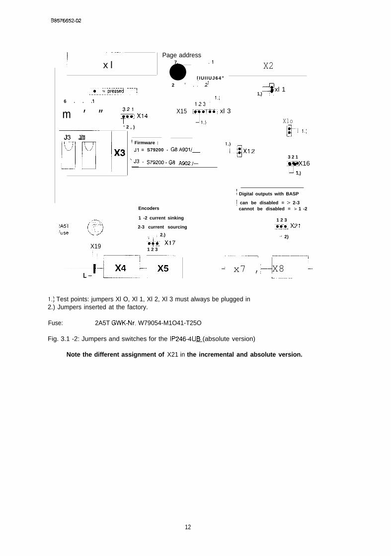
B8576652-02
~...— —.—
]x l
;..o. k--p(gieded ----1L -------------------
6 . . .1
m ’ ” ~x14
‘ 2 , )
F!iFiTJ’ J1
x3
X19;1
Page address7. ,1
● [ IU I IUJ64”
2 7 :-. .2’
1,)
‘ 23 nX15v—O=- xl 3
– 1)
J Firmware :
J1 = S79200 - G8 A901/—
]J3 = S79*O0-G8 A902,—
Encoders
1 -2 current sinking
2-3 current sourcing
,; ‘ ; 2.)
‘& X171 2 3
.—
-----4HzLr[-.--E
X2
4● xl 11,)
Xlo[* ,,,
1,)
1q: xl 23 2 1
F
● ● X161,)
~$••ˆ$•• Digital outputs with BASP
~ can be disabled = > 2-3cannot be disabled = > 1 -2
—.1 2 3
‘6”0-OJ X21..—+
- 2)
. . . . . . . . . . . . . .———= or———–-—–..-—,
L;! x7 ,I
i X8 t-L..——.—
1,) Test points: jumpers Xl O, Xl 1, Xl 2, Xl 3 must always be plugged in2.) Jumpers inserted at the factory.
Fuse: 2A5T GWK-Nr. W79054-M1O41-T25O
Fig. 3.1 -2: Jumpers and switches for the IP246-4UB (absolute version)—
Note the different assignment of X21 in the incremental and absolute version.
12
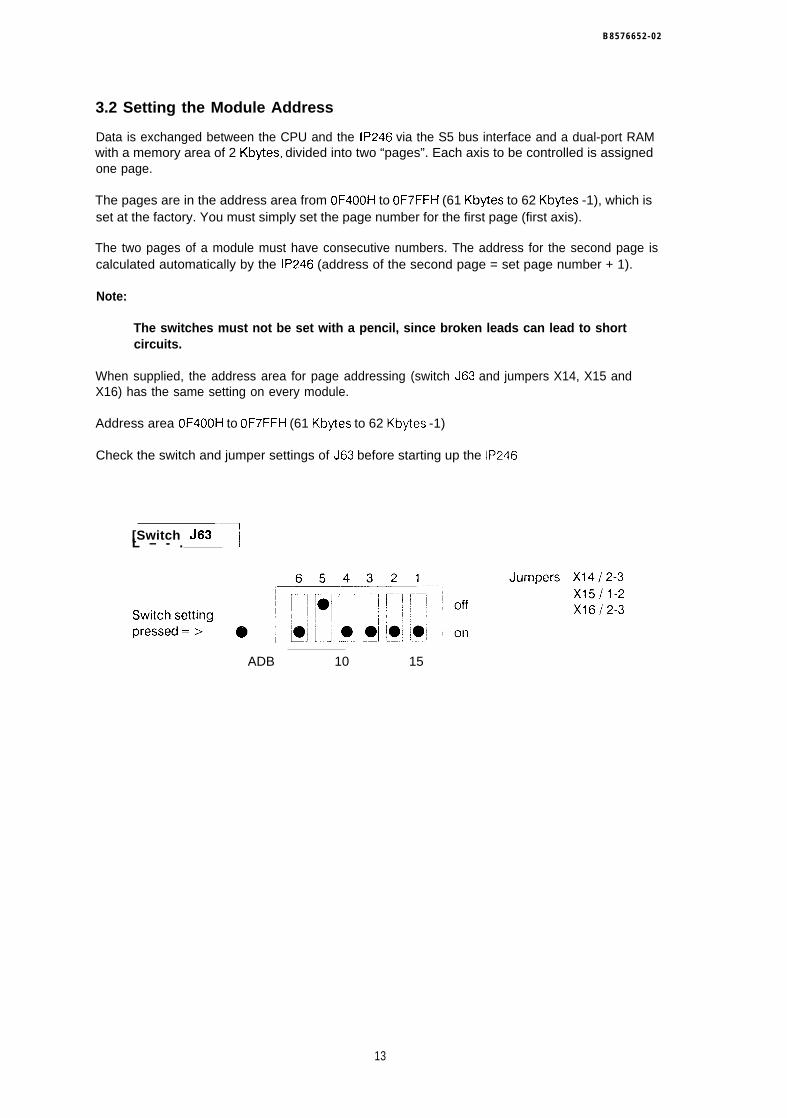
B 8 5 7 6 6 5 2 - 0 2
3.2 Setting the Module Address
Data is exchanged between the CPU and the IP246 via the S5 bus interface and a dual-port RAMwith a memory area of 2 Kbytes, divided into two “pages”. Each axis to be controlled is assignedone page.
The pages are in the address area from OF400H to OF7FFH (61 Kbytes to 62 Kbytes -1), which isset at the factory. You must simply set the page number for the first page (first axis).
The two pages of a module must have consecutive numbers. The address for the second page iscalculated automatically by the IP246 (address of the second page = set page number + 1).
Note:
The switches must not be set with a pencil, since broken leads can lead to shortcircuits.
When supplied, the address area for page addressing (switch J63 and jumpers X14, X15 andX16) has the same setting on every module.
Address area OF400H to OF7FFH (61 Kbytes to 62 Kbytes -1)
Check the switch and jumper settings of J63 before starting up the IP246
[Switch J63 ‘~L – - .
ADB 10 15
13
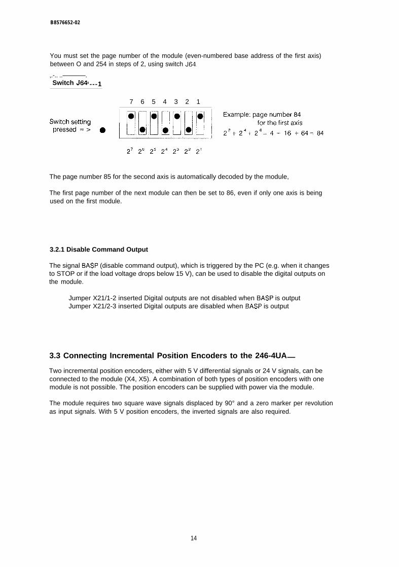
B8576652-02
You must set the page number of the module (even-numbered base address of the first axis)between O and 254 in steps of 2, using switch J64.
,.-.. ..————.~ Switch J64‘---1
7 6 5 4 3 2 1
The page number 85 for the second axis is automatically decoded by the module,
The first page number of the next module can then be set to 86, even if only one axis is beingused on the first module.
3.2.1 Disable Command Output
The signal BASP (disable command output), which is triggered by the PC (e.g. when it changesto STOP or if the load voltage drops below 15 V), can be used to disable the digital outputs onthe module.
Jumper X21/1-2 inserted Digital outputs are not disabled when BASP is outputJumper X21/2-3 inserted Digital outputs are disabled when BASP is output
3.3 Connecting Incremental Position Encoders to the 246-4UA—
Two incremental position encoders, either with 5 V differential signals or 24 V signals, can beconnected to the module (X4, X5). A combination of both types of position encoders with onemodule is not possible. The position encoders can be supplied with power via the module.
The module requires two square wave signals displaced by 90° and a zero marker per revolutionas input signals. With 5 V position encoders, the inverted signals are also required.
14
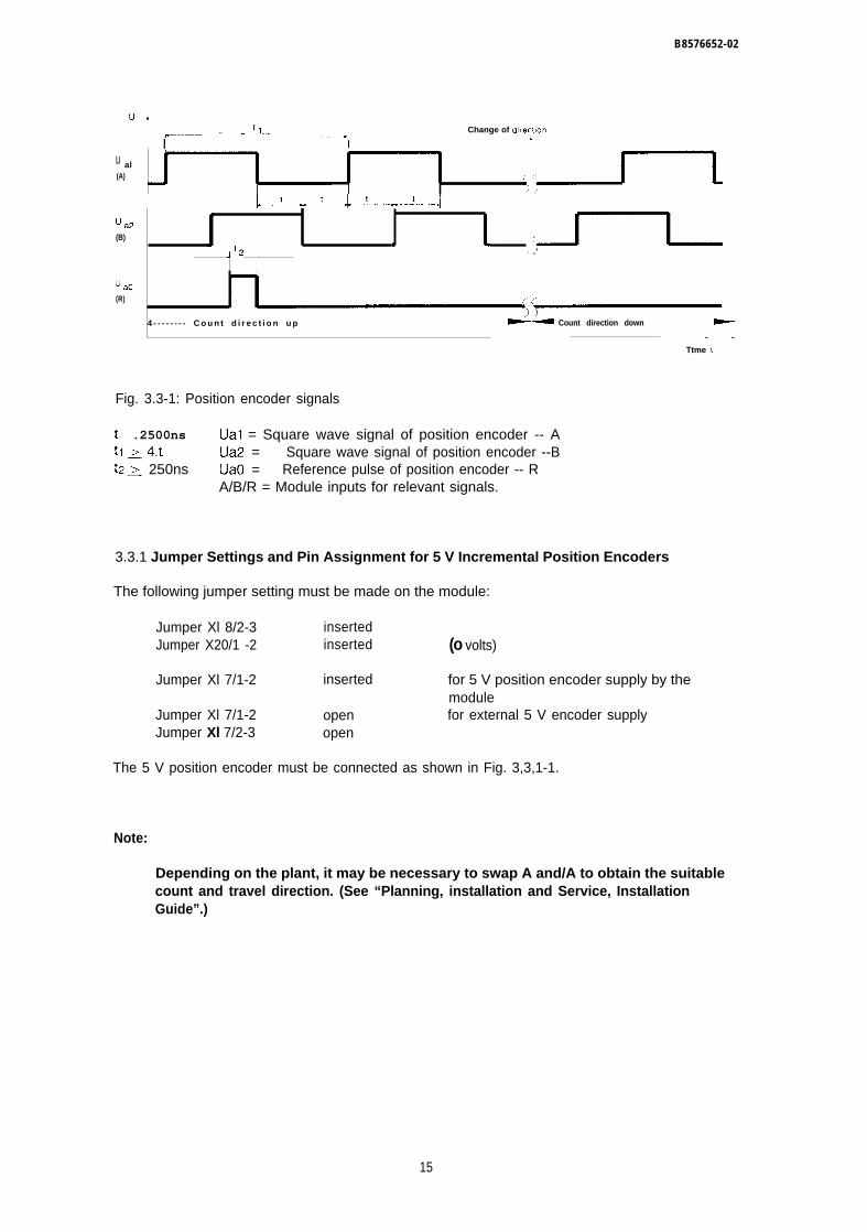
B8576652-02
u+~ tl*—–-——— . . ... -––– ..-..–.. Change of d]recl,on
~••••|Œƒ••‚Œ Iu al(A)
~> ,1
I L.--J---U -W--J--- - iLJaz(B)
J ● 1 . . J_l__J’2 !. ) .’
u aO(R)
‘; ~
4 - - - - - - - - C o u n t d i r e c t i o n u p .- Count direction down -
- -
Ttme 1
Fig. 3.3-1: Position encoder signals
t .2500ns Ual = Square wave signal of position encoder -- Atl > 4.t Ua2 = Square wave signal of position encoder --Btz > 250ns UaO = Reference pulse of position encoder -- R
A/B/R = Module inputs for relevant signals.
3.3.1 Jumper Settings and Pin Assignment for 5 V Incremental Position Encoders
The following jumper setting must be made on the module:
Jumper Xl 8/2-3 insertedJumper X20/1 -2 inserted (o volts)
Jumper Xl 7/1-2 inserted for 5 V position encoder supply by themodule
Jumper Xl 7/1-2 open for external 5 V encoder supplyJumper Xl 7/2-3 open
The 5 V position encoder must be connected as shown in Fig. 3,3,1-1.
Note:
Depending on the plant, it may be necessary to swap A and/A to obtain the suitablecount and travel direction. (See “Planning, installation and Service, InstallationGuide”.)
15
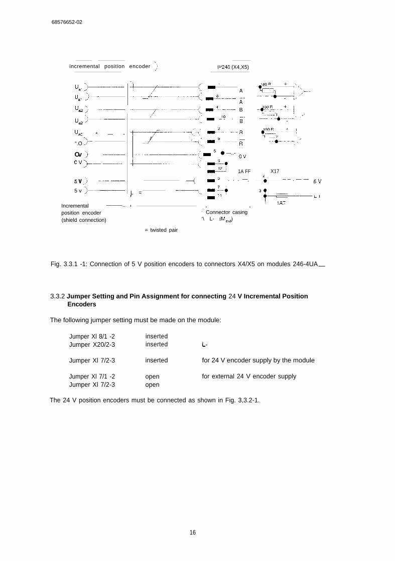
68576652-02
incremental position encoder ~ IP246 (X4,X5)
‘al +-—“,1 ,>u=+-.–..—
“& +—
‘ao * — -
“.O F
Ov ~--–() v >._ —-..--—
5 v )- --–-—5 v >—–—
Incremental ———..
position encoder(shield connection)
L—f=—-( --fl-——u-—––( -.s........ ;~.–.--–----–-<: --4----- B
.~’- - .!.! . ;-’-1
%
. .
/’ -“+; ::”;.-::::
= -:---- ● –-..- ~ v~..
+--–—--–—----–< --~-o--~~’ 1A FF
L =-
—4,, --2-. . . . —=
–-—?. -.;:.,,
-—
l-.– -—.—--..--.————.——~’ Connector casing‘\ L- (Me.,)
= twisted pair
.-+::!93.; .-+–j, ,
------ 4---- ‘“’
‘- +:::.:;-’- ‘-- ‘-!.4- --{.. ‘
X17
--5—– – . — — s v
Fig. 3.3.1 -1: Connection of 5 V position encoders to connectors X4/X5 on modules 246-4UA—
3.3.2 Jumper Setting and Pin Assignment for connecting 24 V Incremental PositionEncoders
The following jumper setting must be made on the module:
Jumper Xl 8/1 -2 insertedJumper X20/2-3 inserted L-
Jumper Xl 7/2-3 inserted for 24 V encoder supply by the module
Jumper Xl 7/1 -2 open for external 24 V encoder supplyJumper Xl 7/2-3 open
The 24 V position encoders must be connected as shown in Fig. 3,3.2-1.
16
B8576652-02
t ‘+
‘-- 2---”-”’’=’””i::,,.–—---2
+-—--–––”::+-’”---- /-–—t,,
I IP246 (X4, X5) !‘ ..-. ,.-1 l?%
_ -’:---- A .~. {.:kj._,J:ojJ; ,0... ,.
_ -’5 - B 6 k I ~ 8kL. LJ 4050
--- ‘3 ----- Rg... .
L-
I- * - - - - - - - - -Connector casing
L- (M J.,
Fig. 3.3.2-1: Connection of 24 V position encoders to the connectors X4/X5 on modules
Note:
248-4UA —
Depending on the plant, it may be necessary to swap A and B to obtain the suitablecount and travel direction. (See “Planning, Installation and Service, InstallationGuide”.)
3.3.3 Pin Assignment of the Connectors for Incremental Position Encoders (X4, X5)
The pin assignment of the two connectors for axis 1 (X4) and 2 (X5) is identical,
Pin Connection for:
1 Square wave signal Al (A2) (TTL)2 Reference signal RI (R2) (TTL)3 Power supply (electronics and light source)4 Square wave signal Etl (B2) (TTL)5 Ground6 Ground7 Power supply (electronics and light source)8 Square wave signal /A1 (/A2) (TTL)9 Reference signal /R1 (/R2) (TTL)10 Square wave signal /B1 (/B2) (TTL)11 Power supply (electronics and light source)12 Ground13 Reference signal R1 (24 V)14 Square wave signal Al (24 V)15 Square wave signal 61 (24 V)
17
B8576652-02
3.3.4 Connectable Position Encoders
Position encoders with open collector output stages cannnot be connected to the incrementalversion of the IP246 owing to the input circuitry. Apart from this restriction, all position encoderswhich meet the signal and power supply requirements can be connected.
3.4 connecting Absolute Position Encoders to the 246-4UB—
You can connect two absolute position encoders with 24 V signals to these modules. Per axisyou can connect up to 20 inputs (bits). You can use either current sourcing or current sinkingposition encoders. A combination of both types is not possible. You can only use positionencoders with Gray code or Gray excess X code ( = > “Fundamentals of Positioning, ReferenceManual”; Section 4.2.4 “Decoding and Evaluation of the Absolute Encoder Value”).
The following jumpers must be inserted on the module:
To connect current sourcing encoders: jumper Xl 7/2-3 insertedTo connect current sinking encoders: jumper Xl 7/1 -2 inserted
The position encoders must be connected as shown in Fig. 3.4-1
(~ Absolute position encoder (jP246 (X4, X5) )
L +.
,- –– {’1 —--–. . . . . . . . . . . . . . . -. PIN 1
‘-+-z
~ . - - - - - - Bit O
- PIN 2
~19 >— ---- ------ Bit 1
Current sourcing I .
~ ~.
switch .
ori i
.
! I 16k 150k
-t”\
21
~%L- 0
6k 8k~
L- ! ——l-j. .-. . . ---- .– < 22 O v
Current sinking~- .-.-: 62,- X17
switch –-l+— = ‘=! ‘. :-::r%t”::%
Absolute “—+---- - ;>0.
position encoder Connector casing
(shield connection) L- (Me.)
Fig. 3.4-1: Connecting absolute position encoders to the connectors X4/X5 on modules246-4tJB—
18
BSS7S6S2-03
3.4.1 Pin Assignment of the Connectors for Absolute Position Encoders (X4, X5)
The pin assignment of the two connectors for axis 1 (X4) and 2 (X5) is identical.
Jack Connection for: Jack Connection for:
12345678910111213
bit Obit 1bit 2bit 3bit 4bit 5bit 6bit 7bit 8bit 9bit 10bit 11bit 12
14151617181920212223242526
bit 13bit 14bit 15bit 16bit 17bit 18bit 19L-L-L-L+L+L+
3.4.2 Connectable Position Encoders
The position encoders which can be connected to the module 246- 4Uf3— must have therequired logical levels and power supply (=> Section 1.4 “Technical Data”).
3.5 Connecting Motor Power Units
Two pdwer units for driving motors can be connected to the module, e.g. transistor DC choppercontrollers for machine tool feed drives.
To achieve optimum adjustment, the drive voltage of the power unit for the rotational speedsetpoint should be in the range from O V...+/- 10 V.
To ensure trouble-free operation, the manufacturer’s guidelines for connecting and wiring thepower units and the general guidelines for SIMATIC S5 equipment should be adhered to.
For each axis, the rotational speed setpoint and ground must be output via a common connector(X6). The power units should be connected according to Fg. 3.5-1. The adjustment of the powerunit (motor standstill, maximum rpm) mu~ be carried out according to the manufacturersspecifications, before connecting to the module.
19
BSS7S6S2-02
:..:; p2&,:@$j:’. . . . . . . . . .%“Nsetl I
2
OV 1 3 (
(
Nset2 4
A 5
Connection to ground
Motor power unit. . . . . . . . . . . . ..,’ .. . . . . . . . . . . . . . . . . . .., :’,...: . . . .,, ,,
.., .’,.,’... . . . . . . . . .
Subrack -
‘ xtwistedzPLC or EU
Fig. 3.5-I: Connection of motor power unns tO the 246-4UA— or 246-4UB_
3.5.1 Pin Assignment of Connector X6 for connecting Motor Power Units
Jack Connection for:
123456789
Rotational speed setpoint NSET1GroundGroundRotational speed setpoint NSET2GroundGrouti---.-.---
3.6 Digital Inputs/Digital Outputs
The digital inputs/outputs for both axes are located on one comrrmn 15-pin connector (X7).Current sourcing switches (contacts, two-wire BEROS) can be connected to the inputs.
Operational signals (controller enable signals and “position reached” messages) are output viashofi-circuit-proof digital outputs.
20

S857S6S2-02
3.6.1 Pin Assignment of Connector X7 for Digital inputs/Digital Outputs
Jack Connection for:
12345678910111213t415
Operational sgnal axis 1Limit switch axis 1Reference point axis 1Position reached axis 1Limit switch axis 1External startktop axis 1---Operational signal axis 2---Position reached axis 2Limit switch axis 2Reference point axis 2---
Limit switch axis 2External startktop axis 2
QIIQII
Q
QII
II
FUM 1ANF 1BEROPR 1END 1START/STOP 1
FUM2
PR 2ANF 2BER02
END 2START/STOP 2
I = input; Q = output
Note:
The limit switches can be specified as normally open (NO) or normally closed (NC). (See“Fundamentals of Positioning, Reference Manual”).
Important safety note:
Fors fa etvreason~ it is ?bso Iutelv vital to interlock the enabling of the power unitwith the ‘“FUM” signal (operational signal)of the IP246! See Section 7.1 ‘TheOperational Signal FUM’’in’’Fundamentalsof Positioning”.
21
1
BSS7SSS2-03
3.7 PG Interface 20 mA
The programmers PG 635, PG 675, PG 685, PG 695 and PG 750 can be connected to the IP246(X8) viasuitable connecting cables (e.g. PG 685 S5 135).
* 12V
1
-’%i5-+ 12V
-’+
PG
2a—3 +*
r -6— + RxD
(al MA)
12—
3
-TxD(-2Qn-A)
23— -,pt.a.
-%
TXD,
RXD+
--JJiip
3—
4—
17—
$
IP246
Fg. 3.7-1: Connecting the programmer to the IP246
To set the transmission rate of the programmer (PG), connections 2,3,4, 17 must be connectedtogether in the connector on the PG side (transmission rate 9600 bps). When using standardcables, this speed is already set.
In the programmable controllersS5135U and S5 155U, the PG interface can also be used via therear panel bus. To do this, the module must be inserted in a suitable slot. The module is thenoperated via the coordinator module (for details, refer to the coordinator instructions).
22
B8576652-02
3.7.1 Pin Assignment of Connector X8 for the PG Interface
Jack Connection for:
123456789101112131415
ShieldRxD ----24 V---TxD +TxD -ShieldRxD +Ground-20 mA/transmitter
-20 mA/receiver..----
3.8 Backplane Connector and Memory Cartridge Connector
3.8.1 Backplane Connector Xl
I i d
~
214 UBATT
—.
6 ADB 12
8 ADB 13
~
10 ADB 14.-.–+--–—–.. --
12 I ADB 15
~ “ = - -
i14 ~
“-1 -
#.- +-.... -
t18 ~
~–-”-–””-–—
~
-.
22
24
t=26-”-{-;s;--””I 28
+--~-–’-’ -- ‘- -
I 30
r- ~ -““ ““”32!—. . .
b
Ground
ADB O
ADB 1
ADB 2
ADB 3
ADB 4
ADB 5
ADB 6
ADB 7
ADB 8
ADB 9
ADB 10
ADB 11
Iz I
/CPKL ~—-—q/MEMR \
/MEMW I
—iDB 1 :
- ---+DB 2 i
-—~DB 3 I
DB 4 j
DB 7 ~--—+
BASP : !f
Ground ~—J
23
3.8.2 Backplane Connector X2
d
Ground I +5V2
4
6
8
10
12—.
14
16
18
20
22
24
—
——
INAU. ,
TxDSn
!
. .
2 6 RxDSn
3.8.3 Memory Cartridge Connector X3
,—— –-/-” -”-”-”---- ‘-”
Ic
1 I1
r—..+ -S.AD-B-’.2...2 SADB O
b
Ground ~ + 5 V ‘–-— .+.
SAD13 1 I SADB 2 ~; .-–..- {
SADB 4 i SADB 5
SADB 7 ~SADB 8 +
1i SADB 3
+~.-=;B–6.-..
SADB 10 \ SADB 11 I
I 6 I SADB13 SADB 14 I /RD
7 I +5V&.fl ---------
SDB 10
SDB 8 SDB 9 ISDB 11 SDB 12 ~
.—— —— .*. ..... –——.9 ~ SDB 1 3 ~ SDB 14
-.——.. - ,. -+ --—--
! 10 ~ SDB O i SDB 1.—.—.. ,
}Ql:::......i.=:12 ! SDB 6 ! SDB 7
1 13 i /ucs I Iucs
~!14L----
SADB 15 iL . – . - . - - . . . . - . . / - - - -
15— .
L . L - T : V– - . . . --, .--:!ound
24
B8576652-02
4 Connecting Cables and Spare Parts
Fuses: IAFF GWK-Nr. C72327-Z87-B12, Pico-Fuse e.g. from WickmannI AT GWK-Nr. W79054-M1O41-TIOO2A5T GWK-Nr. W79054-MI041-T250
For the connection of position encoders, power units and digital signals, standard prefabricatedcables are available as follows:
. . . = length code for connecting cables:5 m BFO10 m CBO20 m CCO32 m CDO
for ROD 220, 270, 420, 426 *) 6ES5 706-0...0
for ROD 320 6ES5 706-1 ...0(installed in 1HU3-, IHU5- and IFT motors)
For SIEMENS encoder &FC9320-3.,. (see SINUMERIC accessories catalog)6ES5 705-5...1
For encoders with 5 V differential signals 6ES5 706-2...0(encoder cable end open)
~..-.-.—.. . . . . . . . . . . r . ... - ~. .—..~Signal ~ Connector ~
~ assignment ~ 15-p ’n ~ Wire color ! Wire ring ;I jack I I I
i—-~-------t-----5- ~ .::--- ~
1-Ov E“- 6 I bk 71
-“””””-”F--- ““-”-”
- - .+Ov—-+J2—
bl ;1
f v +
+
3 rdk--—1 “
–1 *X7 gr I pi
“L”~z---- —1ye,v.—_. ---—
Casing ~ Shield~—— ...--.–– -.-.:– 1
*) With a mating connector, manufacturer CONTACT GmbH (Order no. 201 O4OCB +40100212 + 1298 4400)
25
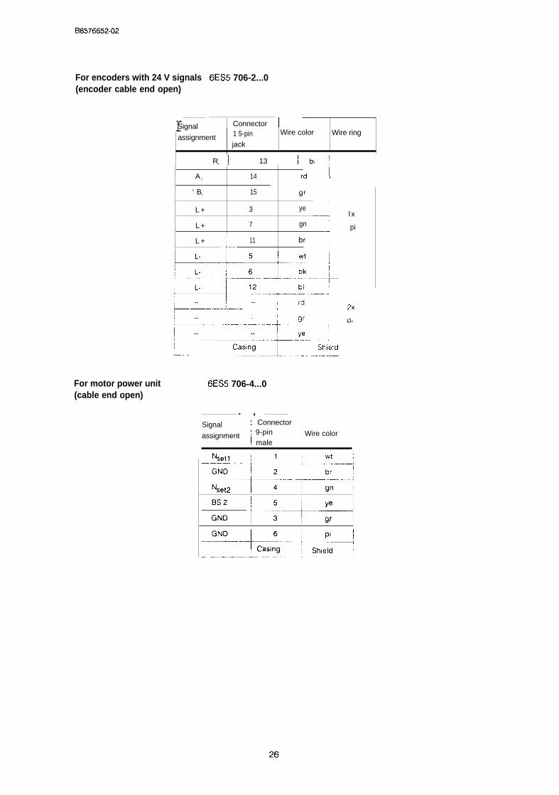
B8576652-02
For encoders with 24 V signals(encoder cable end open)
rSignal
For motor power unit(cable end open)
6ES5 706-2...0
Connector1 5-pin Wire color
assignmentWire ring
jack
I RI I 13 ! bl ;
A l 14 rd IJ
‘ Bl 15 gr ~
L + 3 ye
“---””””1L + 7 gn
L
-jL + 11 br
6ES5 706-4...0
. ,Signal 1 Connector
Wire color
l x
pi
assignment ~ 9-pin! male
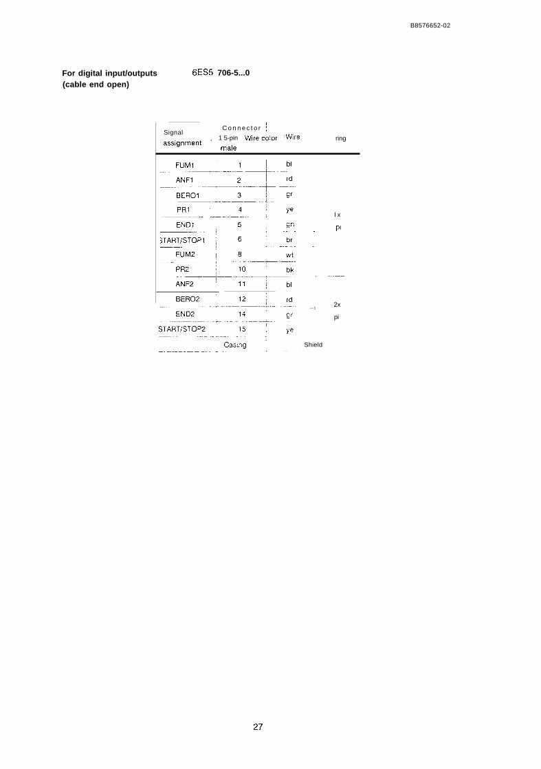
B8576652-02
For digital input/outputs(cable end open)
6ES5 706-5...0
Signal\ C o n n e c t o r ~
! 1 5-pina~~ignment , ~a,e Wirecolor :Wire ring
l x
pl–,
.,
-L—.....—..
—12x
pi
Shield
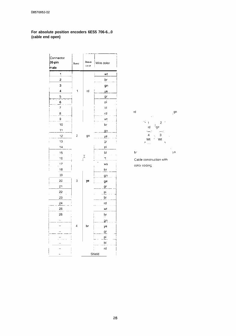
For absolute position encoders 6ES5 706-6...0(cable end open)
;nn;;,
I-L26-pin Bundl
ale
=
2
3
4
~ - : - - - -6;-—----- — .–.. -.-.....-1
I
7 -d~-—
I 19
1
2
3
4
rd
gn
I.i
ye
br
rd,.
,,. .“1 2 ’
(rd gn-.< .—,:,4 ,, 3
Wt ‘ Wt,. . . . . . ,,
br
,
gn:
Shield I

SIEMENS
SIMATIC S5IP246 Positioning
Functions
Module Incremental 6ES5246-4UA31 / -4UA41Absolute 6ES5246-4UB11 / -4UB21
Reference Manual C79000-i38576-C653 -02
B8576653-02
,,
Contents
1 Principle of Operation . . . . . . . . . . . . . . . . . . . . . . . . . . . . . . . . . . . . . . . . . . . . . ........3
20perating instruction . . . . . . . . . . . . . . . . . . . . . . . . . . . . . . . . . . . . . . . . . . . . . . . . . . . . . 6
3Description of the Individual Operating Modes . . . . . . . . . . . . . . . . . . . . . . . . . . . . . . . . 103.1 Jog Speedsl and 2 (Operating Modes 1,2) . . . . . . . . . . . . . . .,, .,, ,,, . . 103.2 Jog Open Loop (Operating Mode3) . . . . . . . . . . . . . . . . . . . . . . . . 113.3 Following ErrorMocfe (Operating Mode4) ..,,,,,,,,,,,,, . . . . . . . . . . . . . . . . ,., ,..., 123.4 Reference/Home Point (Mode5) . . . . . . . . . . . . . . . . . . . . . . . . . . . . . . . . . . 133.4.1 Reference PointApproach (only forthelncremental Version) . . . . . . . . . . . . . . . . . . . . . . . 143.4.2 Set Reference point; Set Home Point . . . . . . . . . . . . . . . . . . . . . . . . . . . . 173.4.3 Special Features when using Absolute Position Encoders . . . . . . . . . . . . . . . . . . . . . . . . . . 183.51ncrementaI ApproachAbsolute (Mode6) . . . . . . . . . . . . . . . . . . . . . . . . . . . . . . . . . . .. ....193.61ncremental Approach Relative (Mode7) . . . . . . . . . . . . . . . . . . . . . . . . . .....203.7 Automatic (Mode8) . . . . . . . . . . . . . . . . . . . . . . . . . . . . . . . . . . . . . . . . . . . . . . . . .......213.8 Automatic Single Statement (Mode9) 223.9 Teach-in On/Off (Modes 10/11) . . . . . . . . . . . . . . . . . . . . . . . . .......243.10 Zero Offset Absolute (Mode 12) . ....,..,,,,,,,, . . . . . . . . . . . . . . . . . . . . . . . . . . . . . . 263.11 Zero Offset Relative (Mode 13) . . . . . . . . . . . . . . . . . . . . . . . . . .......283.12 ClearZero Offset (Mode 14) . . . . . . . . . . .......293.13 ToolOffset (Mode 15) . . . . . . . . . . . . . . . . . . . . . . . . . . . . . . . . . . . .......293.14 ToolOffset Off (Mode 16) . . . . . . 313.15 Clear Error (Mode 17) . . . . . . . . . . . . . . . . . . . . . . . . . . . . . ...,.,,,313.16 Drift Compensation On/Off (Modes 18,19) . . . . . . . . . . . . . . ,,, . . . . . .......323.17 Machine Data Processing (Modes20,21,64, 67and 68) . . . . . . . . . . . . . . . . . . . . .......333.17.1 Enter Machine Data (Mode 20) . . . . . . . . . . . . . . . . . . . . . . . . . . ,,, ,,, ,, .....343.17.2 Delete Machine Data (Mode21) . . . . . . . . . . . . . . . . . . . . . . . . . . . . . .......363.17.3 Read Machine Data Directory (Mode64) .. ....363.17.4 Read Machine Data (Mode67) . . . . . . . . . . . . . . . . . . . . . . . . . .,, , . . . . ..,,...373.17.5 Machine Data Overview (Mode68) . . . . . . . . . . . . . . . . . . . . .......373 . 1 8 E x e c u t i n g M a c h i n i n g P r o g r a m s ( M o d e s 2 2 , 2 3 , 6 5 a n d 6 9 ) . . . . 3 83.18.1 Enter Machining Program (Mode 22) . . . . . . . . . . . . . . . . . . . . .......383.18.2 Delete Machining Program (Mode23) . . . . . . . . . . . . . . . . . . , . .......403.18.3 Machining Program information (Mode65) . . . . . . . . . . . .....413.18.4 Read Machining Program (Mode69) . . . . . . . . . . . . . . . . . . . . . . . . . . . .......413.19 Enter SYSlD(Mocfe24) . . . . . . . . . . . . . . . . . . . . . . . . . . . . . . . . . .......423.20 Read SYSID(Mode 70) . . . . . . . . . . . . . . . . . . . . . . . . . . . . . . . . . . . . . . . . . . . . . . . .......43
4Description ofthelndividual Monitoring Modes . . . . . . . . . . . . . . . . . . . . . . . . . . . . . . . 44
08576653-02
1 Principle of OperationThe module is operated by means of commands, regardless of whether these commands aresent to the IP246 by the CPU or by a programmer. Commands are divided into two basic groups:
instructions for “operating” andcommands for “monitoring”.
Operating instructions are used for the following:
● to set (change) modes,
● to start the execution of a mode,
● to input modifications during the execution of a mode and
● to abandon the execution of a mode
The reaction to an operating instruction depends on various factors.
● The instruction must be feasible.
● It must be feasible in the currently set mode and, if a change of mode is required, also inthe new mode.
● It must not contradict the “axis attributes” which determine whether or not an operatingmode is permissible at a given time ( = > ‘iFundamentals of Positioning, ReferenceManual”, Section 6 “Axis Attributes”).
● It must not contradict the mode of the other axis, if this has already been set by previousoperating instructions (e.g. “teach-in” or “delete program”).
If all these conditions are fulfilled, the operating instruction will be processed, otherwise an errormessage is output and with a few exceptions processing is terminated.
Operating instructions are entered in the appropriate PC or PG job list on the IP246 in the orderin which they are received. In each IP246 cycle (every 3,75 ins), an attempt is made to fetch andinterpret the oldest valid job in this list. If the job is permitted in the current axis status, it isexecuted immediately. If it contradicts the current mode, the mode is terminated and an errormessage output.
Note:
An operating instruction which causes a mode to start should only be transferred to themodule when the previous job is complete.
While an axis is braking, further jobs are accepted, however, not interpreted since they wouldtrigger a stop and the module is already braking. If several jobs are sent to the IP246 during thisphase, it is possible that an entry cannot be made in the job list. These jobs are then lost. TheIP246, however, outputs the error message “PC (or PG) job list is full”.
B8576653-02
With certain operating instructions (transferring a machining program to the IP246), data are alsosent to the module along with the instruction, The reactions in this case are explained in thedescription of the modes.
Monitoring commands are used to fetch the axis attributes (checkback signals), the moduleerrors and information about the actual value, distance to go or following error from the Imodulecyclically. They are independent of the operating instructions and can be sent to the module atany time. They are processed immediately. The next monitoring command can only be input toan interface when the previous command has been processed. Monitoring commands can besent to the positioning module simultaneously by both interfaces, without the commandsinterfering with each other.
I Positioning module
I 1P 246
I
7Job
list
l-—- --–-—‘“-] Operating instructionI ~
.1 1“1+
i L- -.. ... —-.. .—. -~ PG /PCData ~~
I I Monitoring command ,I 1
Positioning module(
1P 246L -
-—...–—L. jPG /PC
Data . .—?’”””
I
Fig. 1 -1: Operating instructions and monitoring commands
Error messages resulting from incorrect operation or an external event (e.g. limit switchresponded) are not reset until they are acknowledged by the input of a new operating instructionat one of the two interfaces. Between the error message and the acknowledgement, any numberof monitoring commands can be entered: the unacknowledged error will continue to be outputalong with the monitoring information.
Each of the axes is always in one of the operating modes. After power on, the following errormode (see below) is set. Within each mode, an axis can be active or idle. This is expressed bythe “axis status” which can have the values “running” or “finished” ( = > “Fundamentals ofPositioning, Reference Manual”, Section 6 “The Axis Attributes”). The axis status can beinterrogated via both interfaces. The axis status appears in the operating modes mask on thePG; on the PC side it can be read in the checkback signals using FB164. ( = > “StandardFunction Blocks FB164 and FB165, User’s Guide”, Sections 2.4 and 2.7.1).
4
I
B 8 5 7 6 6 5 3 - 0 2
In the axis status “finished”, an axis can be changed from one operating mode to any otheroperating mode, providing the restrictions mentioned above are not contradicted. The operatinginstruction includes the required operating mode number and a “command”. The command canbe “start”, “stop”, “forward”, “reverse” or “enter”. The axis then changes to the required mode. Themode is, however, only executed when the set mode and the command represent a feasiblecombination, i.e. “jog speed 1, forwards”. The relationship between commands and individualmodes is explained in more detail in the description of the modes.
If the input is correct, the axis begins to execute the mode. The axis status changes from“finished” to the status “running”. Once the mode is completed, the axis once again assumes thestatus “finished” and can be started again.
If the execution of a mode is to be terminated, you once again send an operating instructionspecifying a mode and the command “stop” to the module. The axis then changes to the“finished” status of the terminated mode. Modes used for data transferor coordinatetransformation cannot be terminated, since this could lead to inconsistencies.
In the “jog” and “incremental” modes (BA 1,2,3,6 and 7) it is also possible to change the speedduring execution (override). This is achieved by once again selecting the mode along with thecommand “enter” and the percentage speed change as a parameter. Here, values of 1 % to 2000/0can be specified. The resulting speed must be in the valid range from 1 -65000 mm/min (or 1 -650000.1 in/rein or 1-65000 deg/min) and must not result in the maximum speed programmedin the machine data record being exceeded. If the maximum speed would otherwise beexceeded, the speed is changed to the maximum upper or lower limit and the error message“speed range exceeded” is output.
5
B8576653-02
2 Operating Instruction
An operating instruction consists of the following parts:
- Axis 1 or e.g. jog - start
- Axis 2 incremental - stop
automatic - forward
etc. - reverse
- enter
r-– —--—- I !I
Parameter ~I—.. .<. .
- according to
the mode
e.g. speed
Fig. 2-1: Structure of an operating instruction
The relationship between modes, operating instructions and the axis status can be seen in thefollowing diagram:
- stop command
- automaticallyowing to error
- operator error
Enter (change)
L
I
‘---=c~-~.ommand:
r -- - - - - - - - - - - - -
‘<startf o r w a r d
Axis status reverse,)
T’
finished!- ..” :...– .–...
L-–. . . . . . . . . .-.---——-.–_-–jOperator error
Fig. 2-2: Relationship between operating instruction and axis status
You can only change or start a mode in the axis status “finished”, This is achieved by the start,forward or reverse command in conjunction with the required mode, The module itself changesautomatically to the following error mode (mode 4) and switches O V or a voltage adjusted by thedrift compensation to the output when certain errors occur, even while a mode is running.

B 8 5 7 6 6 5 3 - 0 2
Such errors include the following:
● “position loop interrupted”
and with the absolute version the errors:
● “illegal absolute encoder reading”
● “illegal change of absolute encoder value”
If these errors occur, no closed-loop position control is possible.
Operating instructions entered while a mode is running and which do not contain an entercommand, result in the error message “illegal job” and the current action is terminated. If anoperating instruction is simply incorrect, the axis remains in the “finished” status. The axis canchange from the “running” status to the “finished” status for a number of reasons. These includethe following:
● a stop command in the particular mode,
● an operator error (e.g. “enter” command with a different mode),
● an error resulting from an external event (e.g. external stop command or a limit switchbeing tripped) or
● the correct completion of a job (e.g. approach to a particular target point or entry ofmachine data).
The enter command is required for the following tasks:
● for override changes during an active job,
● to trigger a single traversing movement in the “automatic single statement” mode,
● to acknowledge a “programmed halt” in the “automatic” or “automatic single statement”modes or
● to store statements in the teach-in mode,
When entering instructions at the PG, remember that everything you enter faster than can beprocessed by the PG or by the COM246 software is written to a keyboard buffer in the PG. If allthe stored inputs are feasible and correct, they will be entered in the PG job list in the order inwhich they were input and then processed by the IP246. This can lead to a stop command beingdelayed.
The modes of the IP246 can be selected both by the PC and PG interfaces.
7

B6576653-02
The operating modes of the IP246,
The following modes can be called directly by COM246 and by the PC via FB164:
●
●
●
●
●
●
●
●
●
●
●
●
●
●
●
●
●
●
●
1- Jog speed 1
2- Jog speed 2
3- Jog open loop (position controller off)
4- Following error
5- Reference/home point (approach or set)
6- Incremental (target approach) absolute
7- Incremental (target approach) relative
8- Automatic
9- Automatic single statement
10- Teach-in on
11 - Teach-in off
12- Zero offset absolute (set actual value)
13- Zero offset relative
14- Clear zero offset
15- Tool offset
16- Tool offset off
17- Clear error
18- Drift compensation
19- Drift compensation off
The following modes are used by the C0M246 automatically in the test mode and can be calledby the PC via FB164:
● Modes 71, 72, 73, 74: (for monitoring modes, see Section 4 “Description of the IndividualMonitoring Commands”)
8

B 8 5 7 6 6 5 3 - 0 2
The following modes can be called indirectly by COM246 by means of function keys and by thePC via FB165:
●
●
●
●
●
●
●
●
9
●
●
●
20- Enter machine data
21 - Delete machine data
22- Enter machining program
23- Delete machining program
24- Enter SYSID (module identifier)
64- Read machine directory
65- Read machining program directory
66- Read actual values (monitoring mode)
67- Read machine data
68- Machine data overview
69- Read machining program
70- Read SYSID (module identifier)
B8576653-02
3 Description of the Individual Operating Modes
In this description of the modes, it is assumed that you are familiar with the terms “machinedata”, “machining program” and “axis attributes”. A detailed description of these terms can be befound in “Fundamentals of Positioning, Reference Manual” in the Sections:
● 4 Machine Data and their Structure,● 5 Machining Programs and their Structure and● 6 Axis Attributes.
3.1 Jog Speeds 1 and 2 (Operating Modes 1,2)
In these two operating modes, it is possible to move an axis at a constant speed. The basicspeeds themselves are contained in the machine data. There are two speeds for forwardsmovements and two for reverse movements which can be selected with the operating modes jogspeed 1 and 2.
After selecting one of the two operating modes, you can start an axis moving in the requireddirection by setting the commands “forward” or “reverse”. By pressing the stop key on the PGyou can stop the axis again. From the programmable controller’s side, FBI 64 provides a specialfeature. On the signal edge of the “forward” or “reverse” command from O to 1, the axis is movedin the selected direction and is stopped again when the signal changes from 1 to 0, The axis alsostops if a stop command is entered ( = > “Standard Function Blocks FBI 64 and FBI 65, User’sGuide”, Section 2.9.2 “Special Features of the Parameters VORW and RUCK”).
v’ Forward stop
I ~~„•€&„•
1, : . .-.—---- ------- . . . . . . . . .
+“”
./’,-/ /
\ . \
‘ I
T./,-
‘ ~ ’ ” ” ” ” ” ”
tstop Reverse
t: time
v: speedFig. 3.1 -1: Traversing in the jog mode
You can also switch from one jog speed to the other while the axis is moving, The axis thenstops and continues its movement in the new jog mode. This also applies to jog open loop (seebelow).
In the jog mode (BA 1 to 3) and in the incremental mode (BA 6 and 7), you can change the basicspeeds stored in the machine data. To do this, you must enter a value between 1 % and 2000/0 inthe “override” parameter. Values outside this range are restricted to the limit values. Thetraversing movement is then executed at the specified percentage of the speed programmed inthe machine data. You can also change the speed while the axis is moving by changing theoverride parameter and entering the “enter” command.
10
B8576653-02
v
Forward Enter Enter stop40Y0 80Y0 120Y0
, 1,, , 1,..-..1,,
\\-—
tt: time
v: speed
Fig. 3.1-2: Traversing in the jog mode with variable speeds
Note:
Traversing speeds resulting from an override change must not exceed the programmedmaximum speed. The limits are 1 -65000 mm/min (or 1 -650000.1 in/rein or 1 -65000deg/min). If this maximum speed would otherwise be exceeded, the speed is changed tothe lower or upper limit and the error message “speed range exceeded” is output.
You can also specify override in steps of 19!o. This accuracy of speed change is also taken intoaccount internally.
3.2 Jog Open Loop (Operating Mode 3)
The open-loop jog mode corresponds to “jog speed 2“ except that the closed-loop positioncontroller is switched off. Instead of the following error, the programmer now displays the speedcalculated from the signals of the position encoder. Accurate display of the speed is onlypossible if the position encoder has correct parameters and the resolution is correctly assigned.The accuracy of the display is reduced the lower the speed and the less accurate the resolution.
Using the open-loop jog mode you can check the adjustment of the power unit or theassignment of parameters to the drive. The speed displayed on the programmer in the open-loopmode should roughly correspond to jog speed 2 in the machine data. If this is not the case, thepower unit of the drive should be readjusted or the machine data corrected.
The setpoint of the position controller is updated in the open-loop jog mode to avoid jolting theaxis when the closed-loop position controller is re-enabled. This allows you to switch betweenclosed and open-loop modes as required.
Using the absolute version of the IP246 you can only traverse in the open loop jog mode withouta position encoder connected if you have assigned parameters for an absolute position encoderwhich does not output Gray excess X code.
11
B8576653-02
3.3 Following Error Mode (Operating Mode 4)
During normal IP246 operation the closed-loop position controller is always enabled, i.e. as soonas the axis deviates from the setpoint position the controller attempts to correct the deviation. Bystarting the following error mode, the position controller is switched off. This is always necessarywhen the IP246 is to evaluate the signals of the position encoder but
● the power unit is switched off for some reason and the drive can no longer follow themanipulated variable, e.g. when the axis is moved manually or if it becomes jammed
● when the power unit is controlled by an external analog voltage.
If the position controller is switched on, a following error would accumulate. If this remains in thepermitted range, the axis would jerk suddenly to the original setpoint position when the powerunit is switched on again or when the IP246 is switched back to closed-loop operation.
When the following error mode is active:
● the position controller is switched off,
● the setpoint output is set to O V, or to a value adjusted by the drift compensation,
● the following error is cancelled,
● the movements of the axis are measured as speed and displayed as in mode 3 instead ofthe following error,
● the position setpoint follows the position actual value. This means that when the followingerror mode is deactivated, the current actual position value is accepted as the set point forthe controller, avoiding jerky movements.
The reference or home point and therefore also the stipulated coordinate system remainunchanged. A selected backlash value is also taken into account in the following error mode,You can, for example, move the axis within the range of the backlash manually without changingthe actual position value. If, however, you move the axis so that there is “play” in the drive (lessthan the backlash compensation value) the backlash is not taken into account with the nexttraversing job when the following error mode is switched off. The backlash is only taken intoaccount by the IP246, i.e. compensated, when a traversing distance greater than the backlashcompensation value in the machine data is travelled. Only then can you assume that there is noplay in the drive (= > “Fundamentals of Positioning, Reference Manual”, Section 4.7 “CorrectionParameters”). If the rotational speed control loop remains switched on in the following errormode, the axis must not move or at most very slightly, If the axis does however move, the powerunit has a drift and must be readjusted. If the movement is only very slight, the deviation may becorrected in the “drift compensation” (BA 18) mode.
The following error mode can be disabled by the operating instruction
● ollowing error, stop 1 or by
● “external stop”.
12
B8576653-02
The position controller is then reactivated. The stop command, in conjunction with a differentmode sent from the PC, does not terminate the following error mode, but simply leads to theerror message “illegal job”.
With the absolute version of the IP246, if the following error mode was switched on automaticallyowing to the error “illegal absolute encoder reading” or “illegal change of absolute encodervalue”, then the machine data can also be changed while the following error mode is active. Thefollowing error mode is then terminated. If one of these errors occurs again after the machinedata have been changed, the module once again switches to the following error mode.
3.4 Reference/Home Point (Mode 5)
Operating mode 5 is used to calibrate the axis. This means the following for incremental positionencoders:
● Reference point approach: the reference point is located by a calibration run. Thereference point precontact (e.g. BERO) and the zero marker of the position encoder areevaluated.
● Set reference point: the current position of the axis (at rest) is assigned the coordinate ofthe reference point stored in the machine data. A precontact and the zero marker of theencoder are ignored.
For absolute position encoders this means the following:
● Set home point: the position signal currently being supplied by the position encoder atrest is assigned the coordinate of the home point. From the information about the encoderresolution and the travel resolution from the machine data, an absolute positioncoordinate is calculated for all other position encoder signals.
In each case, an error-free machine data record is required on the module. The coordinate of thereference or home point is stored in the machine data. With the incremental version, the directionof approach to the reference point and the speeds for approaching the reference point are alsocontained in the machine data record.
Note:On correct completion of mode 5, the checkback signal “reference/home point set” is sent. ( = >“Fundamentals of Positioning, Reference Manual”, Section 6 “Axis Attributes”).
If the reference/home point is not set, the software limit switches stipulated in the machine dataare not evaluated and the following operating modes are blocked:
“incremental absolute” (mode 6),“automatic” (mode 8),“automatic single statement” (mode 9) and“teach-in on” (mode 10).
Zero offsets and tool offsets which were active before the calibration of the axis ( = > Section3.10 or Section 3.11 “Absolute/Relative Zero Offset” and Section 3.1.3 “Tool Offset”) are retainedand are included in the calculation of the reference/home coordinate.
13
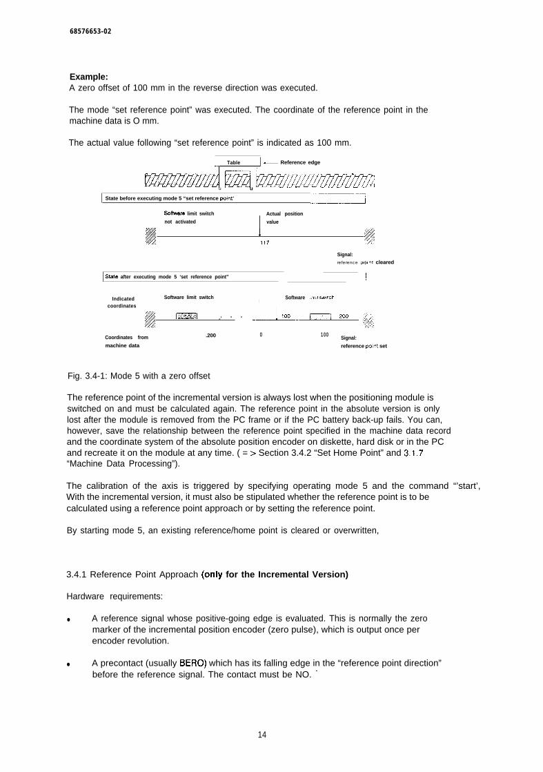
68576653-02
Example:A zero offset of 100 mm in the reverse direction was executed.
The mode “set reference point” was executed. The coordinate of the reference point in themachine data is O mm.
The actual value following “set reference point” is indicated as 100 mm.
1, Table _ Reference edge
Ezmzamdmb Jzmzzzz..< . .&/
.)
u u
State before executing mode 5 “set reference point”‘——-
Wfware limit switch Actual position
not activated
1
value
##
117 /</,
Signal:reference po, nt cleared
State after executing mode 5 ‘set reference point” !
Indicated Software limit switch Software I!mlt sw!tchI
coordinates
~.., % .,:= -1 0 0 .L-. m,. g
‘2A;
Coordinates from .200 0 100 Signal:machine data reference po(nt set
Fig. 3.4-1: Mode 5 with a zero offset
The reference point of the incremental version is always lost when the positioning module isswitched on and must be calculated again. The reference point in the absolute version is onlylost after the module is removed from the PC frame or if the PC battery back-up fails. You can,however, save the relationship between the reference point specified in the machine data recordand the coordinate system of the absolute position encoder on diskette, hard disk or in the PCand recreate it on the module at any time. ( = > Section 3.4.2 “Set Home Point” and 3,1.7“Machine Data Processing”).
The calibration of the axis is triggered by specifying operating mode 5 and the command “’start’,With the incremental version, it must also be stipulated whether the reference point is to becalculated using a reference point approach or by setting the reference point.
By starting mode 5, an existing reference/home point is cleared or overwritten,
3.4.1 Reference Point Approach (only for the Incremental Version)
Hardware requirements:
● A reference signal whose positive-going edge is evaluated. This is normally the zeromarker of the incremental position encoder (zero pulse), which is output once perencoder revolution.
● A precontact (usually BERO) which has its falling edge in the “reference point direction”before the reference signal. The contact must be NO. “
14
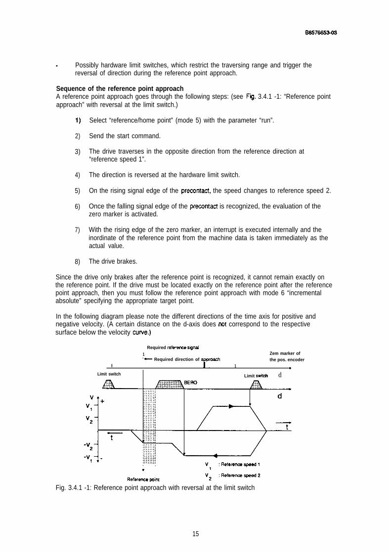
aS!57ee530S
. Possibly hardware limit switches, which restrict the traversing range and trigger thereversal of direction during the reference point approach.
Sequence of the reference point approachA reference point approach goes through the following steps: (see Fg. 3.4.1 -1: “Reference pointapproach” with reversal at the limit switch.)
1)
2)
3)
4)
5)
6)
7)
8)
Select “reference/home point” (mode 5) with the parameter “run”.
Send the start command.
The drive traverses in the opposite direction from the reference direction at“reference speed 1”.
The direction is reversed at the hardware limit switch.
On the rising signal edge of the precontact, the speed changes to reference speed 2.
Once the falling signal edge of the precontact is recognized, the evaluation of thezero marker is activated.
With the rising edge of the zero marker, an interrupt is executed internally and theinordinate of the reference point from the machine data is taken immediately as theactual value.
The drive brakes.
Since the drive only brakes after the reference point is recognized, it cannot remain exactly onthe reference point. If the drive must be located exactly on the reference point after the referencepoint approach, then you must follow the reference point approach with mode 6 “incrementalabsolute” specifying the appropriate target point.
In the following diagram please note the different directions of the time axis for positive andnegative velocity. (A certain distance on the d-axis does not correspond to the respectivesurface below the velocity cuwe.)
Required referenm signsJ1 Zem marker ofv +- Required direction of the pos. encoder
I 1●
Limit switchI Limit stitch d
Fig. 3.4.1 -1: Reference point approach with reversal at the limit switch
15
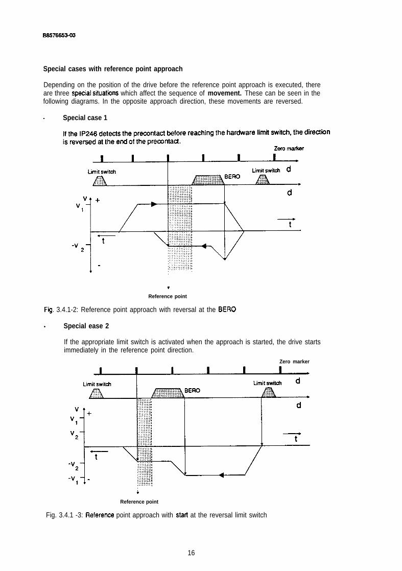
ass7sss303
Special cases with reference point approach
Depending on the position of the drive before the reference point approach is executed, thereare three speoial situat”nns which affect the sequence of movement. These can be seen in thefollowing diagrams. In the opposite approach direction, these movements are reversed.
. Special case 1
v
Reference point
Fg. 3.4.1-2: Reference point approach with reversal at the BERO
. Special ease 2
If the appropriate limit switch is activated when the approach is started, the drive startsimmediately in the reference point direction.
Zero marker
+Reference point
Fig. 3.4.1 -3: Referenoe point approach with starl at the reversal limit switch
16
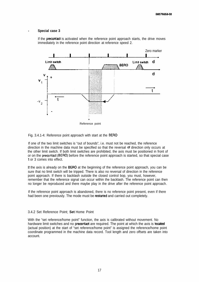
.
as5766s3-03
Special case 3
If the precontact is activated when the reference point approach starts, the drive movesimmediately in the reference point direction at reference speed 2.
Zero marker
‘1
-v2
;Reference point
Fig. 3.4.1-4: Reference point approach with start at the BERO
If one of the two limit switches is “out of bounds”, i.e. must not be reached, the referencedirection in the machine data must be specified so that the reversal of direction only occurs atthe other limit switch. If both limit switches are prohibited, the axis must be positioned in front ofor on the precontact (BERO) before the reference point approach is started, so that special case1 or 3 comes into effect.
[f the axis is already on the BERO at the beginning of the reference point approach, you can besure that no limit switch will be tripped. There is also no reversal of direction in the referencepoint approach. If there is backlash outside the closed control bop, you must, however,remember that the reference signal can occur within the backlash. The reference point can thenno longer be reproduced and there maybe play in the drive after the reference point approach.
If the reference point approach is abandoned, there is no reference point present, even if therehad been one previously. The mode must be restafied and carried out completely.
3.4.2 Set Reference Point; Set Home Point
With the “set reference/home point” function, the axis is calibrated without movement. Nohardware limit switches and no precontact are required. The point at which the axis is bcated(actual position) at the start of “set reference/home point” is assigned the reference/home pointcoordinate programmed in the machine data record. Tool length and zero offsets are taken intoaccount.
17

I
06S766S3-03
A reference or home point can be set at any axis position, even outside the hardware limitswitches. You must, therefore, make sure that your axis is in a permissible position within thehardware limit switches before executing the “set referencehme point” mode. Remember thatthe programmed software limit switches may, under certain circumstances, be outside thehardware limit switches mounted on the axis and therefore have no effect.
If a backlash compensation value is assigned other than O, the referencehome point must onlybeset when there is no play in the drive. The first traversing movement (traversing distancegreater thatiequal to the assigned backlash) must be in the direction in which there is no play,since the backlash is not taken into account with this traversing nmvement (=> Part 2,“Fundarnentalsof Positioning”; Section 4.7.1 “Backlash Compensation”).
3.4.3 Specfal Features when using Absolute Position Encoders
In the “set home point” mode, the bit pattern of the Gray code currently being transmitted by theencoder is assigned the coordinate of the reference point from the machine data. Only after thisis the module capable of recognizing the actual position of the axis from every bit pattern of theabsolute encoder. Zero point adjustment of the position encoder is not required!
Since the module loses this assignment without data back-up, e.g. when the module is removed,the current code from the position encoder is entered in the machine data record on the moduleand identified as valid when a reference point is set. This identification cannot be read orinfluenced directly via COM246. The entry is overwritten the next time a reference point is set.
Save the machine data record with the valid home point, both in the CPU and on diskette. If thisdata record is once again loaded on the module after a module has been exchanged, a “setreference point” is not required again, providing the mechanical coupling between the positionencoder and axis is not changed. The module then once again outputs the actual position of theaxis.
As soon as the following are changed in the machine data, the allocation is invalid:
. the encoder data,
. the travel resolution,
. the module number or
. the axis number.
When working with COM246, this occurs automatically. If the data manipulation is in the CPU orexternal, you must make sure that the “valid bit” is reset (=> Part 6 “Standard Function BlocksFB164 and FB16S; Section 3.8.1 “Structure of a Machine Data DB in the PC Memory”).
Changing the home point coordinate in the machine data record leads to a physicaldisplacement of the traversing range, and does not clear the home point.
18
B8576653-02
Proceed as follows after replacing the position encoder:
position the axis on the physical home point in the “jog” or “incremental relative” mode,
execute the mode “set reference/home point”,
save the machine data again.
With the IP246, the zero of the position encoder does not require adjustment!
If the position encoder does have a zero adjustment and this was carried out correctly for bothposition encoders, so that both encoders supply the same bit pattern at the same axis position,then “set home point” does not need to be repeated.
Response of the module when the PC is switched on:
● If there are no machine data on the module, the actual value remains constant zero.Checkback signal (axis attribute): “machine data not present”, “home point missing”.
● If machine data are present, but there is no home point, then the actual value is the sameas the coordinate of the home point from the machine data after the machine data areentered without zero offsets or tool length offsets. If the axis moves, the actual value isupdated.Signal: “home point missing”.
● If machine data exist with a valid home point, the actual value is correctly indicated andupdated.Signal: “home point set”.
During operation any number of absolute position encoder overflows may occur. The modulestill calculates the correct absolute values. When stipulating the coordinate system, you mustmake sure that an absolute encoder position is read, which can be assigned to a coordinatewithin the limits resulting from the coordinates of the software limit switches and the decelerationramps. This range is known as the “usable range” ( = > “Fundamentals of Positioning, ReferenceManual”; Section 4.3 “Traversing Range”).
3.5 incremental Approach Absolute (Mode 6)
In this mode, a target specified in absolute coordinates is approached. The speed of theapproach is the basic speed (1 OOYO) specified in the machine data “incremental speed”, You canvary this speed with override between 1 % and 200Y0. The resulting speed must, however, notexceed the maximum speed. See “jog” modes 1..3, The target position must be within thesoftware limit switches or range limits. The mode can only be executed when there is areference/home point.
With a linear axis the movement is triggered by the start command.
19
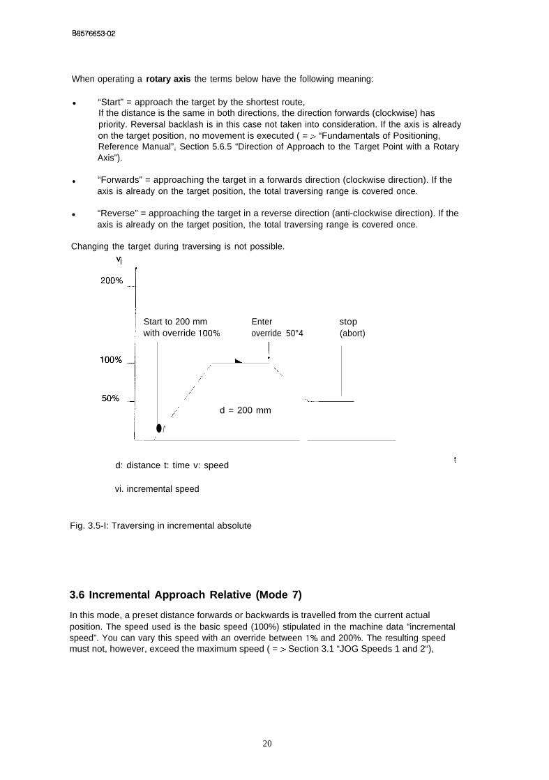
B8576653-02
When operating a rotary axis the terms below have the following meaning:
● “Start” = approach the target by the shortest route,If the distance is the same in both directions, the direction forwards (clockwise) haspriority. Reversal backlash is in this case not taken into consideration. If the axis is alreadyon the target position, no movement is executed ( = > “Fundamentals of Positioning,Reference Manual”, Section 5.6.5 “Direction of Approach to the Target Point with a RotaryAxis”).
● “Forwards” = approaching the target in a forwards direction (clockwise direction). If theaxis is already on the target position, the total traversing range is covered once.
● “Reverse” = approaching the target in a reverse direction (anti-clockwise direction). If theaxis is already on the target position, the total traversing range is covered once.
Changing the target during traversing is not possible.
Start to 200 mm Enter stopwith override 10OYO override 50°4 (abort)
k1/, .,
,/’ ...,
/“,/ . .../’” d = 200 mm
● /’/ —
d: distance t: time v: speed
vi. incremental speed
Fig. 3.5-I: Traversing in incremental absolute
3.6 Incremental Approach Relative (Mode 7)
t
In this mode, a preset distance forwards or backwards is travelled from the current actualposition. The speed used is the basic speed (100%) stipulated in the machine data “incrementalspeed”. You can vary this speed with an override between 1 % and 200%. The resulting speedmust not, however, exceed the maximum speed ( = > Section 3.1 “JOG Speeds 1 and 2“),
20

08576653-02
This mode can also be executed when the reference or home point is deleted. The traveldirection is determined by the operating instruction “forwards” or “reverse”.
v ) Forwards 200 mm Enter stop
override 100% override 50% (abort)
I/’ ~~~~~ .-.1
100%
Iso% \~———-
d = 200mm.
‘.“\ \ . .
d: distance t: time t
v: speed
Fig. 3.6-1: Traversing in “incremental approach relative”
With a linear axis, the distance to be travelled must be such that the resulting target position witha reference or home point set remains within the traversing range between the two software limitswitches (also taking into account zero point offsets). If this is not the case, the job is abortedand the error ‘traversing range exceeded” is displayed. With a rotary axis, the distance travelledis limited to +/-40 m (+/-4000 inches, +/-40000 degrees). If this limit is not adhered to, the jobis also aborted and the error message “illegal dist. spec.” is generated.
3.7 Automatic (Mode 8)
A series of traversing movements, dwell times and loops can be stored on the module as amachining program. The structure and effects of machining programs or of functions inmachining programs is discussed in “Fundamentals of Positioning, Reference Manual”, Section 5“Machining Programs and their Structure”. To execute a machining program, you must specifythe parameter “program number” in the operating instruction. The machining program isexecuted with the “start” command. You can abandon the program at any time with the “stop”command. The distance to go then remains unchanged until the next traversing movement. Theprogram is terminated after a stop command. You can only start again from the first statement,and not from the point at which the program was interrupted. For the automatic mode, thereference or home point must be set. While a machining program is being executed you can notchange or delete this program.
Machining programs stored on the module are not assigned to a particular axis. They can beused by both axes simultaneously. If the machine data or your plant contradict the requirementsof the machining program, the IP246 recognizes the error while executing the machiningprogram. The machining program is then terminated for the corresponding axis and an errormessage is displayed.
21
B8576653-02
On the module, a machining program interpreter evaluates the individual statements of themachining program. This interpreter is normally several statements ahead of the statementcurrently being executed. This means that an error such as “statement not allowed after flyingchange” may be signalled before the illegal statement in the machining program has beenexecuted.
Zero offsets can be programmed in machining programs, which are then automatically cancelledagain after the program is completed. If the program is aborted before it is completed, theseoffsets are not automatically cleared. They must be eliminated with BA14 “clear zero offset” ( = >Section 3.12 “Clear Zero Offset”).
Tool length offsets activated in the automatic mode are retained after the machining program iscompleted or aborted.
If a machining program is executed on a rotary axis, the approach to the target by the shortestroute is the default. Since the IP246 calculates the shottest route itself and therefore determinesthe direction, you must make sure when programming a flying change that the flying change ispermitted and does not lead to an error.
Note:
● With a programmed halt (MOO) and a flying change (G1O) in one statement, theprogrammed halt has priority.
● In mode 8 (“automatic”) an enter command is required for each “programmed halt’
● The point at which the program is halted is always immediately before the next traversingmovement or dwell time.
In the following example, a number of unnecessary MOO functions have been used. Beforeapproaching target 200, the enter command must be given three times although the interruptpoint is directly before the movement.
N1O X1OO F1OOO MOON15 ! MOON20 G56 ! MOON25 G43 ! X200 F1OOO M02 (! = halt point)
3.8 Automatic Single Statement (Mode 9)
This mode runs, in principle, in exactly the same as automatic. However, you must supply the“enter” command before a traversing movement or dwell time is executed. Only one traversingmovement or one dwell time in the machining program is executed, any further movement ordwell time must be triggered separately. The halt point is always immediately before the nexttraversing movement or dwell time.
22

B8576653-02
The command sequence with “automatic signal statement” is as follows:
I“Automatic single statement”; program number; start.1
●
●
●
●
●
etc.
The axis changes to the “automatic single statement” mode.
The axis searches for the machining program with the specified program number,
Within the machining program the statements are executed until the first dwell time or firsttraversing movement.
The axis then waits for the enter command.
When the enter command is received, all functions are executed until the next traversingmovement or dwell time.
“Automatic single statement”, stop
With this command, the “automatic single statement” mode is terminated, This can occur bothbetween the execution of two statements or during a traversing movement or dwell time.
Special features
● Statements connected with a flying change are treated as one statement
N1O G1O X1OOO F1OO M1ON20 X2000 F500 . > treated as one statement
Exception● If “flying change” and “programmed halt” are used in one statement, “programmed halt”
●
●
●
has priority.
N1O G1O X1OOO F1OO MOON20 ! X2000 F500 = > separated owing to MOO
CXfsets or switchovers are executed following the program start, following the previoustraversing movement or dwell time and following the programmed halt.
N1O X1OO F1OOO M1ON11 G56! X200 F1OOO Ml 1 = > The execution of the program is only interrupted
after G56(! = halt point)
A “programmed halt” is suppressed in conjunction with a traversing movement and dwelltimes to avoid two enter commands being required.
N1O X1OO F1OOO MOON11 G56 ! X200 F1OOO = > Despite “programmed halt” and single
statement execution, only one enter commandis required (! = halt point)
23
B8576653-02
N1O G74 M1ON15 G90! XIOO F1OOO M O ON20 G56! X200 F1OOO M20 – > C)nly one enter command is required—
at both halt points
In the following cases, the “enter” command must be sent twice:
● Apart from the statement number, only MOO was programmed (N1O MOO)
● [n the statement with MOO, only an offset or switchover was programmed.
3.9 Teach-in On/Off (Modes 10/1 1)
In the “teach-in” mode, only the JOG modes and modes “incremental approach absolute orrelative” are permitted, other entries are not executed, If no position was stored in “teach-in”, thepositioning module will have generated an empty machining program.
The following procedure must be followed to generate machining programs in “teach-in”:
. the mode BA1O must be activated and the required program number specified,
o the required target points must be approached in “JOG” or in the mode “incrementalapproach absolute or relative”,
● with the axis at a standstill (axis status = “finished”), the current actual position must bestored in the selected program with the enter command. The storing of the statement issignalled with the message “statement stored. It is possible to transfer the position severaltimes. In this case, several identical machining program statements with a consecutive Nfunction are stored in the machining program,
● after storing all target positions, switch off the “teach-in” mode with BA11 (“teach-in off”)The program is then completed with M02 and entered in the program directory of themodule.
A program generated in this way can be used in both automatic modes by both axes.
In the “teach-in” mode, all statements
● are stored one after the other,
● begin with NO1 and have a consecutive N function,
● are assigned “incremental speed” 100Yo and
● are stored without M functions
When “teach-in” is switched on
● the machine data record must be valid,
● the reference/home point must be available,
24

08576653-02
● there must be sufficient space in the program memory of the IP246,
● a machining program number must be specified which has not yet been used on theIP246,
● the other axis of the IP246 must not be in the “teach- in” mode and
● machining program input must not be active on the other axis.
Note:
If the power supply to the positioning module is switched off during “teach-in” and ifstatements have already been recorded, this machining program is lost. The “teach-in”mode is no longer active. If the limit of maximum 10000 machining program characters isexceeded in “teach-in”, the mode is automatically terminated, the last stored statement istaken as the final statement.
The following command sequence is for example possible: (in the example, the incrementalspeed in the machine data is 2500 mm/s)
9
●
●
●
●
●
●
●
“Teach-in on” (mode 10), program 7, start“Teach-in” is switched on and machining program 7 is set up.
“’’JOG speed 1“ (mode 1), 20Y0, forwardsThe axis moves forward at 20Y0 of JOG speed 1.
“JOG speed 1“ (mode 1), 50Y0, enterThe axis continues in a forwards direction at half JOG speed 1.
“JOG speed 1“ (mode 1), stopThe axis stops (e.g. at 1258,250 mm). After the “finished” message, the enter commandcan be used to enter the machining program statement. ( = > “Fundamentals ofPositioning, Reference Manual”, Section 6 “Axis Attributes”).
“JOG speed 1“ (mode 1), enterThe axis is now stopped. With the enter command, the first statement NO1 X1258,25F2500 of machining program 7 is generated.
“incremental approach absolute” (mode 6), 3000 mm, startThe axis travels to the absolute position 3000 mm and stops. The “finished” message is set
“Incremental approach absolute” (mode 6), enterN02 X3000 F2500 is entered in the second statement (N2).
“Teach-in off” (mode 11), startMachining program 7 is completed and the teach-in mode switched off. The statement N3M02 is appended to machining program 7 to indicate the end of the program.
25
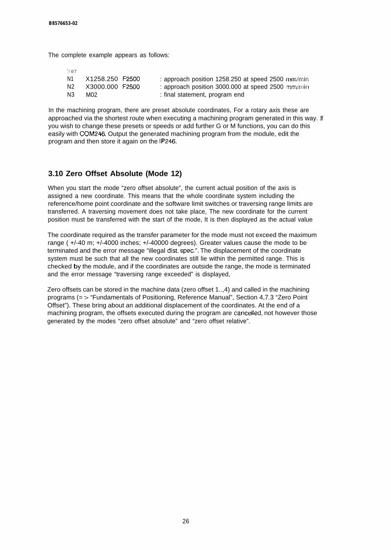
B8576653-02
The complete example appears as follows:
0/07
N1 X1258.250 F2500 : approach position 1258.250 at speed 2500 mm/minN2 X3000.000 F2500 : approach position 3000.000 at speed 2500 mm/minN3 M02 : final statement, program end
In the machining program, there are preset absolute coordinates, For a rotary axis these areapproached via the shortest route when executing a machining program generated in this way. Ifyou wish to change these presets or speeds or add further G or M functions, you can do thiseasily with COM246. Output the generated machining program from the module, edit theprogram and then store it again on the IP246.
3.10 Zero Offset Absolute (Mode 12)
When you start the mode “zero offset absolute”, the current actual position of the axis isassigned a new coordinate. This means that the whole coordinate system including thereference/home point coordinate and the software limit switches or traversing range limits aretransferred. A traversing movement does not take place, The new coordinate for the currentposition must be transferred with the start of the mode, It is then displayed as the actual value
The coordinate required as the transfer parameter for the mode must not exceed the maximumrange ( +/-40 m; +/-4000 inches; +/-40000 degrees). Greater values cause the mode to beterminated and the error message “illegal dist. spec.”, The displacement of the coordinatesystem must be such that all the new coordinates still lie within the permitted range. This ischecked by the module, and if the coordinates are outside the range, the mode is terminatedand the error message “traversing range exceeded” is displayed,
Zero offsets can be stored in the machine data (zero offset 1..,4) and called in the machiningprograms (= > “Fundamentals of Positioning, Reference Manual”, Section 4,7.3 “Zero PointOffset”). These bring about an additional displacement of the coordinates. At the end of amachining program, the offsets executed during the program are cancelled, not however thosegenerated by the modes “zero offset absolute” and “zero offset relative”.
26
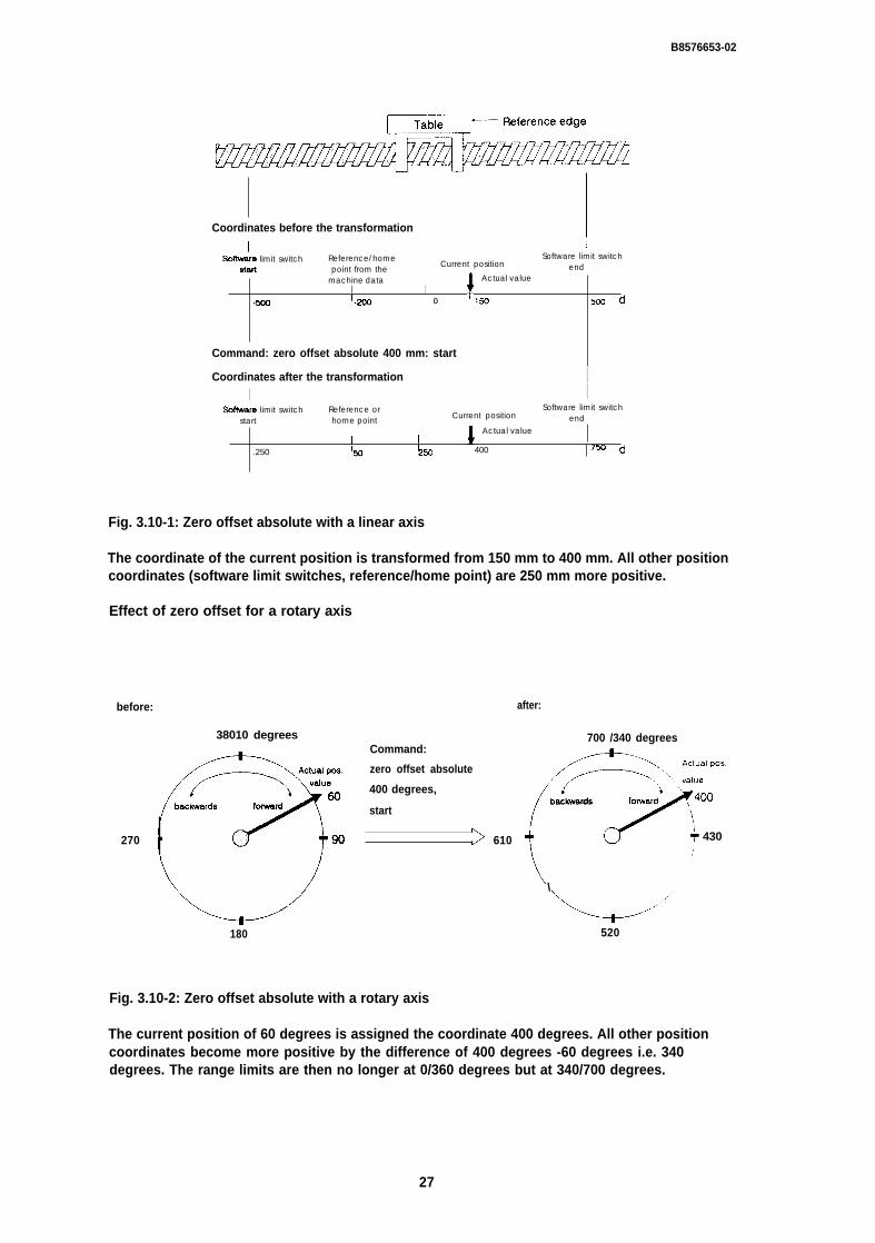
B8576653-02
Coordinates before the transformation
I ISoffw&e limit switch Reference/home
Current positionSoftware limit switch
stall point from the endmachine data
fActual value
I I.5W !-ml o 1S) 5cocf
Command: zero offset absolute 400 mm: start1
Coordinates after the transformation II I
Soflware limit switch Reference or Software limit switchstart home point Current position end
fActual value
I I.250 ‘w ’250 400 75n d
Fig. 3.10-1: Zero offset absolute with a linear axis
The coordinate of the current position is transformed from 150 mm to 400 mm. All other positioncoordinates (software limit switches, reference/home point) are 250 mm more positive.
Effect of zero offset for a rotary axis
before:
38010 degrees
270
180
Command:
zero offset absolute
400 degrees,
start
>
Fig. 3.10-2: Zero offset absolute with a rotary axis
after:
610
700 /340 degrees
(
+=;’’:::::backwards
/,
foruard
\
- 430
\
“=-+-””520
The current position of 60 degrees is assigned the coordinate 400 degrees. All other positioncoordinates become more positive by the difference of 400 degrees -60 degrees i.e. 340degrees. The range limits are then no longer at 0/360 degrees but at 340/700 degrees.
27
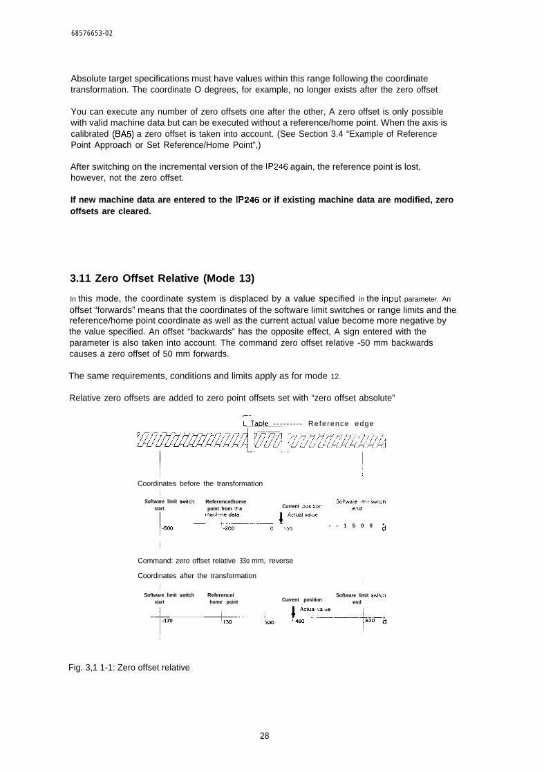
68576653-02
Absolute target specifications must have values within this range following the coordinatetransformation. The coordinate O degrees, for example, no longer exists after the zero offset
You can execute any number of zero offsets one after the other, A zero offset is only possiblewith valid machine data but can be executed without a reference/home point. When the axis iscalibrated (BA5) a zero offset is taken into account. (See Section 3.4 “Example of ReferencePoint Approach or Set Reference/Home Point”,)
After switching on the incremental version of the IP246 again, the reference point is lost,however, not the zero offset.
If new machine data are entered to the IP246 or if existing machine data are modified, zerooffsets are cleared.
3.11 Zero Offset Relative (Mode 13)
In this mode, the coordinate system is displaced by a value specified in the input parameter. An
offset “forwards” means that the coordinates of the software limit switches or range limits and thereference/home point coordinate as well as the current actual value become more negative bythe value specified. An offset “backwards” has the opposite effect, A sign entered with theparameter is also taken into account. The command zero offset relative -50 mm backwardscauses a zero offset of 50 mm forwards.
The same requirements, conditions and limits apply as for mode 12.
Relative zero offsets are added to zero point offsets set with “zero offset absolute”
r-
L Table - - - - - - - - - Reference edge
I /Coordinates before the transformation
ISoftware limit switch Reference/home Scflware Ihm(f sw,lch
start point from the Current pos,taon end
+
“:+;----+O ?;;’”:::”: - - 1 5 0 0 ~
II
Command: zero offset relative 33o mm, reverse
Coordinates after the transformation
I I
Software limit switch Reference/ Software limit sw!lchstart home point Current position end
f
-170 +--+-4?’=-–-+3.,
Fig. 3,1 1-1: Zero offset relative
28
B8576653-02
3.12 Clear Zero Offset (Mode 14)
When this mode is started, all zero offsets, established by
● “zero offset absolute”, BA12 or
● “zero offset relative” , 6A 13
or zero offsets which were not cancelled because a machining program was aborted arecleared. (= > Section 3.7 “Automatic”).
If several zero offsets have been performed, it is not possible to clear individual offsets, only thetotal offset can be cleared. The coordinate system is then once again as it was with mode 5.
3.13 Tool Offset (Mode 15)
The “tool offset” mode allows user programs and machining programs to be used when the toollength changes without having to change the program.
In the operating instruction of mode 15, you enter the value and direction of the tool lengthoffset. The direction is stipulated with the commands “forwards” or “backwards”. Remember thatthe sign before the offset value is taken into account. The command “tool offset -80 mm,backwards” corresponds to a tool length offset of 80 mm forwards.
When any positioning movement is carried out, the new tool tip is brought to the specified targetposition. This also applies to the execution of machining programs, If mode 15 is called again,the offset is replaced by a new value.
The mode “tool offset” requires valid machine data. A reference/home point is not necessary. Avalue within the limits of +/-40 m (+/- 4000 inches or +/-40000 degrees) can be entered for thetool length. Values outside these limits lead to termination of the program and to the errormessage “illegal dist. spec.”.
The value displayed as the actual position following a tool offset is the position at which the tip ofthe tool is located. Following a tool offset, even if a software limit switch is tripped, the actualvalue (tool tip) must not exceed the limits of +/-40 m (+/-4000 inches, +/-40000 degrees). Thisis checked when the tool offset is executed. If this condition is not met, the tool offset is notaccepted and the error message “traversing range exceeded” is set.
Example:
A drilling program was written assuming that the drill is 100 mm long. The reference edge of thechuck is position 50 when retracted. Enabling conditions were generated at this position for theequipment, i.e. the chuck must always return to this retracted position. The target position of thedrill tip when operating is 200.
29
B8576653-02
Implementation
BA6 ; 50 mm ; Start ;“incremental approach absolute” to 50 mmBA15; 100 mm ; forwards ;“tool length offset”BA6; 200 mm ; start ;(’incremental approach absolute” to 200 mmBA16; start ;“tool offset” offBA6; 50 mm ; start ;“incremental approach absolute” to 50 Inm
In the parameter for mode 15, only the actual length of the drill is entered. This means that therequired depth is always achieved.
Before the drill is retracted, the offset is cancelled so that the chuck returns to the basic position.
In the program, you must of course make sure that the individual jobs are sent when the axisstatus is “finished”.
Note:
The detection of the software limit switch depends on the internal position setpoint. Theaxis begins to brake when the reference edge of the tool holder passes a software limitswitch. Depending on the tool offset, the tip of the tool may be well outside the selectedtraversing range.
You can also specify a tool offset in the machine data which can be switched on withinmachining programs by G43 or G44. ( = > “Fundamentals of Positioning, Reference Manual”,Section 5.6 “The G Functions”. This offset is added to the offset specified with mode 15 and canbe called repeatedly. This allows, for example, the estimated wear on a tool to be taken intoaccount within the machining program by setting the tool length with mode 15 and then callingthe tool offset from the machine data in the machining program to make up for the tool wear.
The tool offsets executed in a machining program are not cancelled at the end of the program.They are retained just as the tool offset set with mode 15, even after the IP246 is switched off. Ifhowever new machine data are entered or the existing machine data are modified, the existingtool offset is cleared.
Each new tool offset set with BA15 overwrites the previously effective tool offset. This applies tooffsets set with BA15 or switched on during a machining program.
Special features for a rotary axis
If a tool offset of 30 degrees forwards (clockwise) is executed at position 60 degrees for a rotaryaxis, the actual position is then signalled as 90 degrees (tool tip), The actual traversing range is,however, still between O degrees and 360 degrees. The coordinate system is therefore turned.On the other hand, with a zero offset the coordinate system is transformed to a differentnumerical range.
30

B857,6653-02
360 /0 degrees.....--*-..
/ -----/...—–.“:/ -=.,;”. ‘
‘J “\ 60 internal setpoint
(?
reverse foward ,
Tool length offset 30 degrees forward, start
270 & 90 Position of thetool tip
L“180
Fig, 3.13-2: Tool offset with a rotary axis
The calculation of the shortest route in the incremental approach mode is always calculated frormthe tool tip when a tool offset is set with a rotary axis.
Restrictions on tool offsets with a rotary axisThe value of the tool offset or value of the offset resulting from mode 15 and G43/G44 in amachining program must be less than the traversing range, i.e. less than the difference between
range end - range start.
If this condition is not met, either the tool offset set with mode 15 is not accepted and the errormessage “illegal tool offset” is signalled or the machining program is aborted with this errormessage.
3.14 Tool Offset Off (Mode 16)
When this mode is started, all tool offsets are cancelled. If you cancel tool offsets set with mode15 using “tool offset off’, you also cancel the tool offsets set in a machining program ( = >“Fundamentals of Positioning, Reference Manual”, Section 5.6.6 “Tool Length Offset”).
3.15 Clear Error (Mode 17)
Error messages resulting from incorrect operation or an external event (e.g. tripping a limitswitch or receiving an external stop command) remain active until they are acknowledged byentering a new operating instruction to one of the interfaces. While the error message is active,any number of monitoring commands can be sent to the module and the error will be outputalong with the response from the module. In the axis status “finished” you can reset the errormessage with the command “clear error”. Only the module errors are reset ( = > “Planning,Installation and Service”, Section 2“Troubleshooting”j.
31
B8576653-02
3.16 Drift Compensation On/Off (Modes 18, 19)
With the “drift compensation” mode, it is possible to compensate a slight drift in the powerelectronics of the drive.
Drift compensation is not a substitute for correct adjustment of the power unit
The power unit must be adjusted according to the manufacturers’ instructions, i.e,:
● the motor must beat a standstill when the rotary speed setpoint of O V is applied to theinput of the power unit
● at a rotary speed setpoint of + 10 V the motor must rotate in a “forwards” direction at therated speed
● at a rotary speed setpoint of -10 V the motor must rotate “backwards” at the rated speed.
Various influences, e.g. component tolerances or fluctuations in temperature may cause a drifteven with a well adjusted power unit.
At the start of the mode, the axis must be in the “finished” status and the position control loopmust be closed. After the command
“Drift compensation”; start, = > checkback signal: axis status: “running”
the following error is monitored for 4 seconds while the axis is at a standstill. The axis thenchanges to the “finished” status again.
The following error is proportional to the output voltage (rotational speed setpoint) andcorresponds at a standstill to the drift of the power electronics. This voltage constant ispermanently superimposed on the rotary speed setpoint of the position controller on completionof the “drift compensation” mode.
If the drift changes, you can correct the existing compensation value by restarting the driftcompensation mode. The compensation value should never be greater than 1 V (a tenth of themaximum speed). You can compare this before executing the drift compensation. The followingshould be the case:
following error at standstill [mm] . gain factor [l/see] s Vmax [mm/min] / (6010)
Example:
Drive with rated speed vmax = 10000 mm/min at +10 V input signal.Displayed following error at standstill = 1 mm; at a gain (kv) factor of 16,6 l/seeThis corresponds to a drift of approximately -1 V.
32
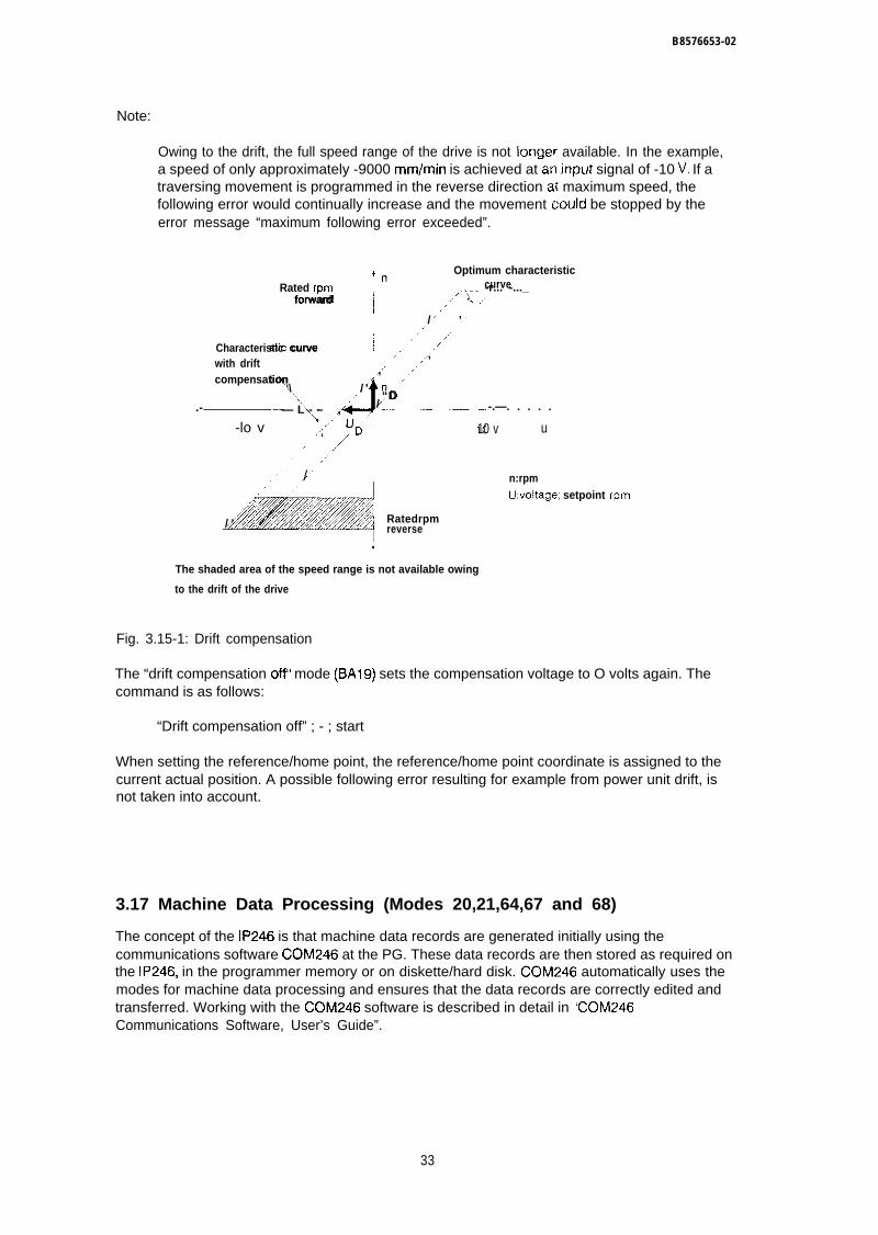
I
B8576653-02
Note:
Owing to the drift, the full speed range of the drive is not longer available. In the example,a speed of only approximately -9000 mm/min is achieved at an input signal of -10 V. If atraversing movement is programmed in the reverse direction at maximum speed, thefollowing error would continually increase and the movement could be stopped by theerror message “maximum following error exceeded”.
POptimum characteristic
Rated rpm curve
,.J’’-------
forward,.k<. -r... -..._
./’ . ,,.
/ ’/’
Characteristic curve ,/’,, .,’/ ,
with drift ,, ‘,compensation ,’
‘\ / ’\ “D.- — L - – , / -.—. . . . .
\-lo v .“ UD’ 10 v u
‘ ,//.,
.,. / n:rpm,. ,,/ /
..;;// h~’~:;) ~“~’U:voltage; setpoint rpm
~ Ratedrpm/ ’ ,< reverse
The shaded area of the speed range is not available owing
to the drift of the drive
Fig. 3.15-1: Drift compensation
The “drift compensation offII mode (BA19) sets the compensation voltage to O volts again. Thecommand is as follows:
“Drift compensation off” ; - ; start
When setting the reference/home point, the reference/home point coordinate is assigned to thecurrent actual position. A possible following error resulting for example from power unit drift, isnot taken into account.
3.17 Machine Data Processing (Modes 20,21,64,67 and 68)
The concept of the IP246 is that machine data records are generated initially using thecommunications software CC)M246 at the PG. These data records are then stored as required onthe IP246, in the programmer memory or on diskette/hard disk. C0M246 automatically uses themodes for machine data processing and ensures that the data records are correctly edited andtransferred. Working with the CC)M246 software is described in detail in “COM246Communications Software, User’s Guide”.
33

68576653-02
Via the PC interface, you can exchange this data between the CPU and IP246 and process it inthe CPU using FBI 65, The procedure is as follows:
● generate the machine data records with COM246, transfer them to the IP246, test andoptimize the machine data
● save the data on diskette or hard disk using COM246
● if necessary, save the data with FBI 65 in a data block in the CPU
● if required, store the data block from the CPU in an EPROM
● if required, modify individual data for particular applications in the CPU and transfer thedata record again to the IP246,
Remember that the same machine data record which you fetched from the CPU to diskette withSTEP 5 is not identical to the machine data record which you transfer to diskette using thesoftware package COM246.
The modes for machine data processing are as follows:
● BA 20 “enter machine data”
● BA 21 “delete machine data”
● BA 64 “read machine data directory”
● BA 67 “read machine data”
● BA 68 “read machine data overview”
3.17.1 Enter Machine Data (Mode 20)
Using this mode a complete machine data record is transferred via the PG interface or PCinterface to the IP246. COM246 uses mode 20 indirectly when the appropriate function key ispressed. If you transfer a machine data record from the CPU to the IP246, you must assignparameters to FB165 as described in “Standard Function Blocks FB164 and FB165, User’sGuide”, Section 3 “Standard Function Block FB165((,
You can only enter machine data when
w the machine data record to be entered has the same module number as the SYSID(module identifier). Otherwise you must first run through mode 24 “enter SYSIDII ( = >Section 3.19 “Enter SYSIDII)
● the axis for which the data are to be transferred is in the “finished” status,
A machine data record can only be transferred via the corresponding interface (axis) to theIP246.
After the transfer, the IP246 checks the consistency of the machine data. If the machine data arecorrect, they are indicated as “existing” in the checkback signals and the digital output “FUM” isset.
34
B 8 5 7 6 6 5 3 - 0 2
If an error is detected in the machine data, the data record is marked by the IP246 by entering anerror number. The functional signal is then reset and O V or a previously calculatedcompensation voltage is output at the analog output,
The error number and corresponding error text are displayed in the error message line ofC0M246 on the PG. Via the PC interface the error number can be evaluated by reading themachine data (BA67) or by reading the machine data overview (BA68).
If the machine data are changed, the position setpoint is set to the actual position value to allowa bumpless transition.
Note:
If the positioning module is removed from the programmable controller, the machine datastored on it are lost (battery back-up via the programmable controller). A reference/homepoint is also lost.
Each time machine data are entered, zero offsets and tool offsets are reset.
If a machine data record is deleted, the reference/home point remains set in the checkbacksignals. After entering a machine data record, the reference/home point is not lost if the machinedata listed below have not changed from those of the old data record. The following data arerelevant:
● number of encoder revolutions (only with the absolute version),
● steps or pulses per encoder revolution,
● distance per encoder revolution,
● reference direction (only with incremental version) and
● the pulse evaluation (only with incremental version).
Additional information about the absolute version of the IP246
With the absolute version of the IP246, the position encoder signal belonging to the home pointis automatically entered in the machine data record on the module following each “set homepoint”. If you save this machine data record on diskette, hard disk or in the PC, you canre-establish the calibration of the axis by transferring the machine data record to the module.Note the conditions explained in Section 3.4.3 “Special Features when using Absolute PositionEncoders”.
If you change machine data, you must make sure that the actual position of the axis remainswithin the traversing range between the software end limit switch and software start limit switchor at least within the usuable range ( = > “Fundamentals of Positioning, Reference Manual”,Section 4.3 “Traversing Range”).
35
B8576653-02
If the position of the axis is outside the usuable range after changing the machine data
● software start limit switch,
● software end limit switch or
● reference/home point
then this point cannot be assigned a unique absolute coordinate, The module reacts with theerror message “actual value not clear” and deletes the home point on the module (checkbacksignal “reference point missing”). The home point remains entered in the machine data record.
If the absolute position encoder is exchanged for a position encoder with the same “number ofrevolutions” and the same “number of steps per encoder revolution”, you must recalibrate theaxis using mode 5 “set home point” or adjust the position encoder exactly as the first one. If theaxis is started up without recalibrating it or without adjusting the zero point, no correct actualpositions will be detected. A stored machine data record containing the home point must notthen be used, since the relationship between the coordinate of the home point and the encoderreading at the home point as contained in the data record is incorrect, You can only delete avalid home point in the machine data record using COM246 by outputting the machine datarecord from the IP246 and changing one of the machine data:
● “number of encoder revolutions”
● “steps per encoder revolutions” or
● “distance per encoder revolution”
and writing the modified data record back to the IP246.
3.17.2 Delete Machine Data (Mode 21)
This mode is used to delete a machine data record on the IP246. The axis involved must be inthe “finished’” status. COM246 uses this mode when the appropriate function key is pressed.Using FB165 via the PC interface you can also delete a machine data record. To do this, themode must be triggered by FB165 via the axis interface.
For more detailed information, refer to the description of FB165 in “Standard Function BlocksFB164 and FB165, User’s Guide(’, Section 3 “Standard Function Block FB 165”.
3.17.3 Read Machine Data Directory (Mode 64)
In this mode, you obtain information from the IP246 about
● the machine data records stored on the IP246 and
● the axis for which the records are valid.
36

B8576653-02
The information for both axes is made available simultaneously. COM246 uses this mode withthe “information function”. If a destination data block is set up in the PC in which the informationcan be entered, you can read the machine data directory using FBI 65 via the PC interface.
For more detailed information, refer to the description of FB165 in “Standard Function BlocksFB164 and FB165, User’s Guide”, Section 3 “Standard Function Block FB165”.
3.17.4 Read Machine Data (Mode 67)
With the “read machine data” mode, a machine data record is transferred from the IP246 either tothe CPU or using COM246 to the PC or to diskette/hard disk. COM246 uses this mode when theappropriate function key is pressed. With FBI 65, you can transfer a machine data record via thePC interface to the CPU. When doing this, you must remember that the machine data record
● must be transferred via the axis interface and
● must be entered in an adequately long destination data block set up in the CPU
You should use this mode to save machine data in the CPU. Only in this way can you exchangea module without using the PG.
For more detailed information about mode 67 refer to “Standard Function Blocks FB164 andFB165, User’s Guide”, Section 3 “Standard Function Block FB165”.
3.17.5 Machine Data Overview (Mode 68)
Using this mode you can read the following information about the machine data on the IP246from the PC side:
● the machine data number of the data record,
● the module number for which the data record is intended,
9 the axis number for which the data record is intended,
● the length of the data record in words and
● the machine data errors.
The overview is transferred simultaneously for both module axes. You must first set up anadequately long destination data block in the CPU.
For more detailed information, refer to “Standard Function Blocks FB164 and FB165, User’sGuide”, Section 3 “Standard Function Block FB165’i.
37
B8576653-02
3.18 Executing Machining Programs (Modes 22,23,65 and 69)
The concept of the IP246 allows machining programs to be created easily using thecommunications soflware COM246 on the PG. These data records are then stored as required
● on the IP246,
● in the programmer memory or
● on diskette/hard disk.
COM246 automatically uses the modes for executing machining programs and makes sure thatthe data records are correctly edited and transferred. Working with COM246 is described in“Communications Software COM246, User’s Guide”.
You can also exchange and process data with F13165 between the CPU and IP246. To do this,proceed as follows:
● create a machining program with COM246, transfer it to the IP246 and test it,
● save the data on diskette or hard disk using CO M246,
● if necessary, save the data in a data block in the CPU using FBI 65,
● if required, store the data block from the CPU in an EPROM,
● if necessary, change the individual data in the CPU for the particular application andtransfer the data record to the IP246 again.
Remember that a machine data record written to diskette from the CPU using STEP 5 is notidentical to the machine data record transferred from the IP246 to diskette using COM246.
The modes for executing machining programs are as follows:
● BA 22 “enter machining program”
● BA 23 “delete machining program”
● BA 65 “read machining program directory”
● BA 69 “read machining program”
3.18.1 Enter Machining Program (Mode 22)
In this mode, a complete machining program is transferred to the IP246 via the PG or PCinterface. COM246 uses mode 22 indirectly if the corresponding function key is pressed. If youtransfer a machining program from the CPU to the IP246, FB165 must be assigned parametersas described in “Standard Function Blocks FB164 and FBI 65, User’s Guide”, Section 3“Standard Function Block FB164”.
38
B8576653-02
The structure of machining programs is described in “Fundamentals of Positioning, ReferenceManual”, Section 5 “Machining Programs and their Structure”.
Since machining programs are not axis related, it does not matter which interface (axis) is usedto transfer the program to the module.
Machining programs are stored one after the other in the memory of the IP246 in the order inwhich they are entered. A maximum of 255 machining programs can be stored on the module.The total number of characters is limited to 10000.
Requirements for the transfer of machining programs areas follows:
● the axis whose interface is to be used to transfer the program must be in the “finished”status,
● the machining program number must not exist on the IP246. It is not possible to overwritea program from the PC side. The old program must be deleted first with BA23 (“deletemachining program”),
● there must be adequate space in the machining program memory of the IP246. (See notein Section 3,18.2, “Delete Machining Program”).
If you wish to execute a machining program after it has been created in the CPU, proceed asfollows:
● create a machining program in DIN representation with COM246. Fill in the input valueswith blanks up to the maximum number of input characters (token characters). Havingdone this, it is easy to change the machining program in the CPU at a later time,
● transfer the machining program to the IP246,
● read the machining program with mode 69 using FBI 65.
The program structure is now set in the CPU data block. You can modify individual parameters inthe ASCII format.
● delete the machining program on the IP246 with FB165,
● enter the machining program to the IP246 using FBI 65 with mode 22
Note:
If the program is extended during the modification, you must update the program length inthe header information, otherwise the entry of the program is aborted with an error!
If a machining program is created with COM246, the machining program can only be transferredto the module if it is syntactically correct. The syntax check is made by COM246. If, however, themachining program is transferred from the CPU to the IP246, the program is checked forsyntactical errors by the firmware on the IP246. If an error occurs, the module error “machiningprogram error” is set. The machining program error itself is written in the machining programheader in DW n +3 ( = > “Standard Function Blocks FB164 and FB165, User’s Guide”, Section3.8.2 “Structure of the Machining Program DB in the PC Memory”). A machining program markedas containing errors is not listed in the machining program directory. It cannot be edited usingthe software package COM246.
39

B8576653-02
If an error is detected, you must proceed as follows:
● read the machining program with mode 69 (“read machining program”) from the IP246 tothe PC memory,
● locate the machining program error in the program and correct it,
Q delete the program on the IP246 with mode 23 (“delete machining program”),
● transfer the program to the IP246 again using mode 22 (“enter machining program”)
When a machining program is created using the software package COM246, a syntax check iscarried out. Whether or not the program is consistent with the machine data can however onlybe determined when the program is executed.
3.18.2 Delete Machining Program (Mode 23)
Using this mode, a machining program is deleted from the IP246 memory, The job is eithertriggered using FB165 via one of the two interfaces or by the software package COM246 bypressing the delete key < F5 > ( = > “Communications Software COM246, User’s Guide”,Section 10 “Delete”). The following requirements must be met:
● the axis of the selected interface is in the “finished” status,
● the program to be deleted is not currently being executed.
If a program is deleted from the program memory of the IP246 while the IP246 is operating(“automatic” or “automatic single statement”) a gap may result in the memory area of the IP246You will then receive the error message “machining program only cleared from directory”. Thisgap can be closed both with COM246 or by the PC as follows:
● read the machining program directory (BA65) from the IP246,
● save the first program on diskette, hard disk or using mode 69 (“read machining program”)in the CPU,
● delete this program on the IP246 with mode 23, The memory of the IP246 is thencompressed,
● transfer the saved program to the IP246 again using mode 22 (“enter machiningprogram”). The program now appears last in the machining program directory,
While the memory is being compressed make sure that neither of the axes is executing amachining program (“automatic”, “automatic single statement” or “teach-in”). If one of thesemodes is being executed, only the memory area after the program currently being executed willbe compressed and no new memory space will be made available.
40

B 8 5 7 6 6 5 3 - 0 2
3.18.3 Machining Program Information (Mode 65)
With this mode, using FB165, you obtain a listing of all the machining programs contained on theIP246. The machining program number and length of the programs in words is output. COM246also uses this mode in the “information function” ( = > “Communications Software COM246,User’s Guide”, Section 11 “Information”). Here, however, the length of the machining programs isshown in bytes.
Since machining programs are not axis related, the machining program directory can be readout by the PC interface via either of the axes. The only condition is that the destination data blockis sufficiently long.
The programs are
● listed in the order in which they are entered and
● entered without gaps in the destination data block.
For more detailed information, refer to the description of FB165 in “Standard Function BlocksFB164 and FB165, User’s Guide”, Section 3,8.5 “Structure of the Machining Program Directory”)
3.18.4 Read Machining Program (Mode 69)
With the mode “read machining program”, a complete machining program is transferred from theIP246 to the CPU. COM246 uses this mode indirectly if the appropriate function key is pressed.Via the PC interface, the transfer is made with FB165. The transfer can be made via either of theinterfaces. The only condition is that the destination data block in the CPU is of adequate length.
When outputting a machining program, the IP246 adds information in the header. This includesthe following:
9 the length of the program in words,
9 the data block number of the machining program on the IP246 (identical to the machiningprogram number),
● if applicable, the machining program error number and
● if applicable, the number of the statement in which the error was recognized
Following this, the machining program is output in ASCII characters.
41
08576653-02
3.19 Enter SYSID (Mode 24)
With mode 24 (SYSID input), a module identifier (SYSID) is entered on the IP246. This isnecessary when a module has been exchanged before transferring machine data.
When operating the IP246 using COM246, the SYSID input does not appear directly, It istriggered when you press < F1 > (begin) in the presetting mask (= > “CommunicationsSoftware COM246, User’s Guide”, Section 4 “Start C0M246”), The data entered and displayed inthe presetting mask are then written to the module.
From the PC side you can execute this mode with FBI 65 via both interfaces,
The module identifier consists of the following elements:
● Module type:
The type consists of the characters “IP2461” to indicate the incremental version of the IP246 orthe characters “IP246A” for the absolute version. The module type cannot be changed.
● Version:
This indicates the firmware version. For example, A02. I for firmware version 2.1. It consists offive characters and cannot be changed,
● Module number:
This is a number between O and 99 which you assign to differentiate between positioningmodules. The same number must also be entered in the machine data of the axes,
Note:
The module number can no longer be changed once a correct machine data record (MD)exists on the module. If you attempt to change this number, the error “correct MD modulenumber cannot be changed” is output.
● Slot number:
This number can be selected between O and 255. It is only used for documentation.
● Page number:
The page number can be selected between O and 255 and is simply used for documentation.The page address set on the module can be entered here ( = > “Hardware, Instructions”, Section3.2 “Setting the Module Address”). The number can then be read at the programmer withouthaving to remove the positioning module from the PC. No check is made as to whether the pageaddress on the module is the same.
42

B8576653-02
3.20 Read SYSID (Mode 70)
Using mode 70 (read SYSID), you can read the module identifier of the IP246 using FB165. Thisis possible via both interfaces. The parameters are explained in the previous section.
For more detailed information about calling mode 70 refer to the description of FB165 in“Standard Function Blocks FB164 and FB165, User’s Guide”, Section 3.8.3.1 “Read SYSID”.
COM246 starts “read SYSID” when you press c F2 > (ONLINE-OFFLINE) in the presetting maskThe data read are then displayed in the appropriate fields (= > “Communications SoftwareCOM246, User’s Guide”, Section 4 “Start COM246”).
43
B8576653-02
4 Description of the Individual Monitoring Modes
Using the monitoring modes, you can call current information from the module. The monitoringmodes are as follows:
Mode number Type Execution with
66 Read actual values FB16571 Actual position value FB16472 Following error FB16473 Distance to go FB16474 Monitoring off FBI 64
The monitoring modes do not appear directly on the PG interface. They are used internally bythe COM246 software package.
Monitoring modes do not influence the operating mode and can be executed at any timeregardless of the axis status,
On the PC interface, the monitoring modes 71, 72 and 73 are started with FB164, the monitoringmode 66 is started with FB1 65.
Function block FB164 continues an activated monitoring function (71, 72, 73) periodically. Youcan stop these monitoring functions with mode 74,
In contrast, mode 66 “read actual values” supplies all three actual values simultaneously usingFB165. These are stored in the destination data block ( = > “Standard Function Blocks FB164and FB 165, User’s Guide”, Section 3.8,6 “Occupation of the Data Area when reading ActualValues”).
For more detailed information about the monitoring modes, refer to the description of functionblocks FB164 and FB165 in the above publication.
44

SIEMENS
SIMATIC S5IP246 Positioning Module Incremental 6ES5246-4UA31 / -4UA41
Communications
Absolute 6ES5246-4UBI 1 / -4UB21COM 246
.—. —.
User’s Guide C79000-B8576-C654 -02
08576654-02
%,
Contents1 Introduction . . . . . . . . . . . . . . . . . . . . . . . . . . . . . . . . . . . . . . . . . . . . . . . . . . . . . . . . . . . . 3
2Definition ofTerms . . . . . . . . . . . . . . . . . . . . . . . . . . . . . . . . . . . . . . . . . . . . . . . . . . . . . . . 7
3Getting Started . . . . . . . . . . . . . . . . . . . . . . . . . . . . . . . . . . . . . . . . . . . . . . . . . . . . . . . . . . 93.1 Consignment . . . . . . . . . . . . . . . . . . . . . . . . . . . . . . ..., ., . . . . . . . . . . . . . . . .. ......93.2 Setting the Configuration Register . . . . . . . . . . . . . . . . . . . . . . . . . . . . . . . . . . . . . . . . .....93.3 Working Copy ofthe COM246 Diskette . . . . . . . . . . . . . . . . . . . . . . . . . . . . . . . . . ........93.3.1 Programmerswith one Floppy Disk Drive (PG685) . . . . . . . . . . . . . . . . . . . . . . . . . ........93.3.2 Programmerswithtwo Floppy Disk Drives (PG675, PG635) . . . . . . . . . . . 103.4 System Configuration . . . . . . . . . . . . . . . . . . . . . .,.,,.,,,,..,...,,,. . 103.4.1 Programmerswithouta Hard Disk (PG675, PG635) 103.4.2 Programmerswitha Hard Disk (e.g.PG685) 113.4.2.1 installing PCP/M . . . . . . . . . . . . . . . . . . . . . . . . ...............,...,.,.,.,.,,,, ...113.4.2.21nstalling COM246 . . . . . . . . . . . . . 12
4Starting COM246 . . . . . . . . . . . . . . . . . . . . . . . . . . . . . . . . . . . . . . . . . . . . . . . . . . . . . . . 13
5 Function Selection . . . . . . . . . . . . . . . . . . . . . . . . . . . . . . . . . . . . . . . . . . . . . . . . . . . . . . 19
61nput . . . . . . . . . . . . . . . . . . . . . . . . . . . . . . . . . . . . . . . . . . . . . . . . . . . . . . . . . . .......216.1 Entering Machine Data, ,,, .,,.,., ,,, ..,,,,.,,,., ,,, .,.,,....,,, . ., . . . . . .......226.1.1 General Information about Machine Data , , . , . , , , , , , , , , . , , , . . . , . . . , , , , . ., ., 22
6.1.2 Compiling Machine Data . . . . . . . . . . . . . . . . . . . . 236.1.2.1 Machine Data Page 1 . . . . . . . . . ., ., ., ., 256.1.2. Machine Data Page2 (incremental Version) . . . . . . .......276.1,2.3 Machine Data Page2 (Absolute Version) . ....,296.1.2.4 Machine Data Page3 . . . . . . . . . . . . . . . . . . . . . . . . . . . . . . . . . . . . . . . ., . . . . .,,.,..316.1.2.5 Machine Data Page4 . . . . . . . . . . . . . . . . . . . . . . . . . . . . . . . . . . . . . . . .......336.1.2.6 Machine Data Page5 . . . . . . . . . . . . . . . . . . . . . . . . . . . . . . . . . . . . . . . . . . 346.1.2.7 Machine Data Page6 (Incremental Version) . .,, , .......366.1.2.8 Machine Data Page6 (AbsoluteVersion) . . . . . . . . . . . . . . . . . . . . . . . . . . . . . .......386.1.3 Print Machine Data . . . . . . . . . . . . . . . ,., ,., ., ., ., ., ,., ., 396.1.4 Assigning Printer Parameters . . . . . . . . . . . . . . . . . . . . . . . . . . . . . . . . . ...............,426.2 Entering Machining Programs . . . . . . . . . . . . . . . . . . . . . . . . . . . . . . .. ....446.2.1 General information about Machining Programs .. ....446.2.2 Generating Machining Programs . . . . . . . . . . . . . . . . . . . . . . . . . . . . . . . . . . . . . .......456.2.3 Entering Machining Programs accordingto DIN . . . . . . . . . . . . . . . 466.2.4 Entering Machining Programs intheText Mode . . . . . . . . . . . .......48
7output . . . . . . . . . . . . . . . . . . . . . . . . . . . . . . . . . . . . . . . . . . . . . . . . . . . . . . . . . . . . . . . . 517.1 Output Machine Data . . . . . . . . . . ., ., ., .517’.2outputMachining program . . . . . . . . ., 51
8Test . . . . . . . . . . . . . . . . . . . . . . . . . . . . . . . . . . . . . . . . . . . . . . . . . . . . . . . . . . . . . . . . . . 538.1 Starting theTest Mode . . . . . . . . . . . . . . . . . . . . . . . . . . . . .. ....538.2 Modes . . . . . . . . . . . . . . . . . . . . . . . . . . . . . . . . . . . . . ,, .,..,,,...,,, . . .......558.3 Mode Table. . . . . . . . . . . . . . . . . . . . . . . . . . . . . . .,, ., .,,.,.., ,.58
9Transfer. . . . . . . . . . . . . . . . . . . . . . . . . . . . . . . . . . . . . . . . . . . . . . . . . . . . . . . . . . . . . . . 61
IO Delete . . . . . . . . . . . . . . . . . . . . . . . . . . . . . . . . . . . . . . . . . . . . . . . . . . . . . . . . . . . . . . . 63
11 Information . . . . . . . . . . . . . . . . . . . . . . . . . . . . . . . . . . . . . . . . . . . . . . . . . . . . . . . . . . . 65
88576654-02
1 Introduction
The programming package COM246 which runs on the PG, provides you with user-friendlysupport for programming and starting up the IP246. All the functions are executed by means ofdialog displays (input fields) and function keys.
If machine data or machining programs are created for the IP246, the data can be stored on theprogrammer (PG), on the module (IP246) or on a floppy or hard disk (FD).
The COM246 soflware package is started by selecting the package from the Komi (command in-terpreter). At the Komi level, a brief description of COM246 can be displayed by pressingfunction key < F3 >. By pressing < F1 >, COM246 is loaded and the first mask, the configurationmask, is displayed. This displays the logo of COM246, The module version must be entered in aninput field. The two possibilities (absolute or incremental version) can be selected using the helpkey < F7 >. The COM246 version and the serial number are displayed, From this mask youbranch to the presetting mask with <Fl > (START),
In the presetting mask, you must select the drive on which the data blocks are to be read andsaved. The drive can be selected using the help key < F7 >, Again using < F7 >, you can selectfiles on the previously selected drive. If there is no file on the selected drive, the name of a newfile must be entered here. In addition to the file name, the fields “plant designation” and “genera-ted by” must be completed. After entering this data, you can change to the next mask withfunction key < F1 > (BEGIN), On the selected drive, a file with the required file name is then ge-nerated. The documentary information “plant designation” and “generated by’” are saved in thefile. If the specified file does not, however, exist, the fields are completed with the stored informa-tion.
Using < F2 > (ONLINE-OFFLINE) you can set the operating mode. The two possible modes areonline and offline. Online, the mode “SYSID output” (BA 70) is executed and the fields with themodule data of the IP246 are completed. The date and time are read from the hardware clock inthe PG and entered in the fields “date-time”. The date and time can still be manipulated. Changesare, however, not transferred to the hardware clock of the PG. If the hardware clock is wrong, itmust be set with the PCP/M-86 program “date” at the operating system level.
By pressing < F1 > (BEGIN) you branch to the basic mask. This mask always indicates theversion of the module (absolute or incremental). In the online mode, the operating mode “SYSIDinput” (BA 24) is executed when you change to the basic mask. The module data, modulenumber, slot number and page address are transferred to the IP246. The slot number and pageaddress are only used for documentation. The module number, on the other hand, can only bechanged when there are no machine data on the IP246. If there are machine data on the IP246,whose module number is not identical with the entry “module no.”, the error message “wrongmodule number” is displayed in the error line.
Using the function keys, machine data and machining programs can now be entered, output, mo-dified, deleted or transferred. Test functions can be executed with the function key < F3 >(TEST).

‘8576654-02
Remember that the following limits apply to files:
maximum number of machining programs per file: 250maximum number of machine data per axis and file: 16maximum number of files which can be selected in the presetting mask with < F7 >: 32
The interactive dialog masks of COM246 include the following elements:
. fixed texts,
● input fields and
. output fields.
The masks are largely self-explanatory. It is, however, advisable to have the User’s Guide at handuntil you are completely familiar with them. The User’s Guide contains descriptions of the masksand explains the significance of the input and output fields. The function keys for each mask areexplained.
Entries are made in the input fields of the masks via the alphanumeric keyboard or using functionkeys (help function). These fields are displayed on the screen inversely, in this description theyhave a grey shaded background. The menu line of each mask is also on a grey shaded back-ground, however, there are no input fields.
Output fields in the masks are used to display COM246 statuses and parameters. Outputsappear on the screen as fixed text. In the following description, they are shown in boxes with abroken line.
In all the masks explained in the following sections, the input fields are already completed withtypical values. The output fields also have values entered. These are in some cases fixed for theparticular mask (operating status) or may change according to the previous entries (parameters).
By pressing the RETURN key, you jump to the next input field. To edit within the input fields, usethe arrow keys.
Error messages from the IP246 and from COM246 are always displayed in the last line (errormessage line). In column 1, the identifier for the current axis is displayed, followed by the charac-ter I and a blank. A O in column 1 stands for a general message. The error message is thenoutput preceded by the error code. From column 60 onwards the error codes of the two axesare once again displayed (axis 1, axis 2).
Example:
1 I F8A reference point missing F8A FOO
The message has the following significance
1 I : the current axis is axis 1,
F8A reference point missing: axis 1 is not calibrated,
F8A–FOO: axis 1 is signaling the module error 8A, axis 2 is not signaling a module error,

08576654-02
t INPUT II MOOUL :~~N–l% ! SIMATIC S5 / COM246,—-——— —-—.
~—––– ————-– —––. --. .–––-. –- . . - .~M–A–C–FjNE_D~~L - – - - - - – - - - - - - - - - – ! DEVICE :riPz46--–-l BLOCK : DB ; 1 2 3
,——— —-1 .-. ..—, , - - - - - -Module : \.l_l––– J Axis : , 1 I Meas. system : m mL. ---— l-- .’ Axistype : :~LN-<A-fl ~
Maximum deceleration f-~;;j{ec-]9 0 0 0 ~--------------- ,.; (10...9999)
Acceleration W. ICOO / [mmlsec-] ; (10...9999)
Oeceieration hvd. Iolw / [mmlsec-] ;. . . . . . . . . . . . . . . . . (10...9999)
Acceleration rev. 15(XI ~ [mmlsec-] ~ (10.,.9999)
Deceleration rev. 1500 :-[M-MG=:”-”--”-: (10...9999)
F I F2 F3 64 F5 F6 ~ F7 F8
NEXT PREVIOUS PRINTEXIT
1 = header ,2 = softkeys = input field ~ = output field(-— —— —--—-—
Fig. 1-1: Mask for entering machine data
The masks are structured so that you can always recognize the current operating status. At thetop left INPUT and below this M A C H I N E D A T A may be displayed. This shows that thecurrent function involves input of machine data. In the output field MODUL the previously selec-ted version of the module (incremental or absolute) is displayed, the DEVICE output field dis-plays the target device and the BLOCK field displays the DB no. for these machine data. Theoutput fields module, axis, meas. system and axis type indicate the values from the previousmask.
The actual machine data can now be input in the five input fields (shown on a grey background)
Travel data, speeds and rates of acceleration always refer to the measuring system selected inthe machine data record. The appropriate dimension is therefore always displayed followinginput fields (e.g. for machine data input) and output fields (e.g. actual position value of the axis),
Using the function keys c F1 > and c F2 > further machine data pages can be called. Withfunction key < F4> the machine data can be printed out on a connected printer. By pressingfunction key < F6> the machine data are transferred to the selected device. < F8> brings youback to the basic menu without transferring the machine data.
5
B 8 5 7 6 6 5 4 - 0 2
2 Definition of Terms
Pc : programmable controller for SIMATIC S5
Operating system: COM246 runs under the operating system S5-DOS. Remember that S5-DOSitself consists of the operating system PCP/M-86 and the additional functionsprovided by the ZEFU diskettes. These functions are activated with “S5” Theoperating system is not supplied with COM246 and must be orderedseparately if not already available.
CO M246: programming package for user-friendly operation of the intelligent 1/0module IP246.
Function key: in the programming package COM246, function keys are the eight keysimmediately below the screen indicated by < F1 >... < F8 >.
IP246: intelligent 1/0 module of the SIMATIC S5 range. With this module, you canoperate two independent axes.
Mask: the display used for input and output of data on the monitor.
Menu: inverse display of function keys < F1 >... < F8 > and a text to indicate thefunction currently assigned to this key
PG: programmer for SIMATIC S5 (e.g. PG635, PG675, PG685, PG695 andPG750).
In this User’s Guide, the following conventions have been used for all commands entered at theprogrammer:
● The equality sign ( = ) at the start of a line indicates the beginning of a new activity
● The greater than character ( > ) at the start of a line indicates a keyboard input.
● Keyboard inputs start with the character displayed by the currently active program as asystem prompt. This is followed by the characters to be input shown in bold upper casecharacters.
● <CR > stands for carriage return.
● < F1 > < F8 > stand for the function keys F1 F8

B8576654-02
3 Getting Started
3.1 Consignment
Under the order number 6ES5 895-5 SA22, the manual includes, among other things, this User’sGuide, a 5 1/4 inch diskette and a 3 1/2 inch diskette with the file:
S5PDC09X,CMD
The software package COM246 runs under the operating system S5- DOS, which is not part ofthe consignment.
3.2 Setting the Configuration Register
If the operating system S5-DOS has never run on your PG, you must set the configuration regi-ster of the PG using the test diskette. You must enter the memory capacity, the drive configura-tion and other important PG characteristics in the configuration register to be able to informvarious programs (e.g. S5-DOS) of the hardware configuration. To set the configuration register,you must insert the test diskette supplied with the PG in drive A: and start the PG either byturning on the power or by using the key switch. Answer the prompt “CHANGE CONFIGURA-TION?” with “Y” and then mark the appropriate information with “+” and the incorrect informationwith“-”. Once you have answered all the questions, you can remove the test diskette and continuewith PCP/M after a cold restart. The content of the configuration register is retained even whenpower is switched off.
3.3 Working Copy of the COM246 Diskette
Before you use the COM246 diskette, you should make a working copy and put the originalaway for safekeeping. To make a copy, use the PCP/M utility “DSKMAINT”, with which you cancheck, format and copy diskettes.
3.3.1 Programmers with one Floppy Disk Drive (PG685)
—— PCP/M system diskette”1 of n“ in drive A:—— Start the PG by turning on the power or using the keyswitch> A > DSKMAINT <CR >—— New diskette in drive A:> < F5 > < F1 > Y < F8 >—— COM246 diskette in drive A:> < F3 > < F1 >
9
B8576654-02
—— Formatted diskette in drive A:> < FI > Y—— Insert the diskettes required by DSKMAINT in drive A:, the COM246 diskette is the
source diskette and the newly formatted diskette is the target diskette.> ‘c F8 > < F8 >
3.3,2 Programmers with two Floppy Disk Drives (PG675, PG635)
————>——>——>>
PCP/M system diskette”1 of n“ in drive A:Start the PG by turning on the power or using the keyswitchA> DSKMAINT <CR >New diskette in drive A:< F5 >< F1 > Y < F8 >COM246 diskette in drive B:< F3 > c F3> < F1 > Y< F8 > < F8 >
3.4 System Configuration
3.4.1 Programmers without a Hard Disk (PG675, PG635)
To work with COM246 effectively, it is advisable to create a system diskette on which all the requi-red programs are available, i.e. programs from the software package “PCP/M” should be copiedto one diskette:
——.—>——>>>>——>>>>>>>>>
PCP/M system diskette”1 of n“ in drive A:Start the PG by turning on the power or using the keyswitchA > DSKMAINT <CR >New diskette in drive B:< F5 > < F3 > Y < F8 > < F8 >A> PIP <CR>*B:= PCPM.SYSIRVl <CR>*B: = CCP.CMD[R~ <CR >ZEFU diskette”3 of n“ in drive A:*B: =S5VVX200X.CMDIRVl c CR >*B: = S5W)(201X.CMDIRVl <CR >*B: = S5WX202X.CMDIRVl < CR >*B: = S5WX204X.CMD[RV] < CR >*B: = S5WXOOOH.CMDIRVl <CR >*B: = S5WX100X.CMDIRVl <CR >*B: = S5KDS02X.CMD[RV] <CR >*B: = S5.CMDIRVl <CR >* < CR >
This diskette now contains the operating system “PCP/M” and all the S5-DOS programs yourequire to work with COM246. If this system diskette is correct, you should make it read-only by
10
B857665LM32
placing a tab over the notch, since you should only read from this diskette when working withCOM246. To avoid having to repeat this operation if the diskette is damaged or lost, you shouldmake a copy of this diskette and keep it in a safe place.
Apart from the system diskette, you also require the COM diskette with the COM package whichwill later also contain the machine data and machining programs in the form of data blocks. Youcreate this diskette by formatting a new diskette (DSKMAINT). Following this, the COM packagecan be copied to this diskette.
—. PCP/M system diskette”1 of n“ in drive A:> A> PIP <CR>—— Newly formatted diskette in drive B:—— COM246 diskette in drive A:> *B: =S5PDC09X.CMD <CR>> * < CR >
With the PG635, the procedure is analogous depending on the S5- DOS release.
3.4.2 Programmers with a Hard Disk (e.g. PG685)
Programmers with a hard disk have the advantage that almost all programs and data can be ac-cessed directly owing to the high capacity of the hard disk. This means that several SIMATICprogram packages can be located simultaneously on the same data medium.
3.4.2.1 Installing PCP/lvl
If your programmer is new and PCP/M is not yet installed, you must first format the hard diskwith the PCP/M utility “HDFORM6” (see PCP/M User’s Guide, page 6-29).
Note:
From issue 1.0/5 (1.0/6 for PG695) HDFORM6 has been replaced by HDPARTY. Pleaserefer to the manual for further information.
Caution!
When formatting the hard disk, all programs and data already on the disk are lost!!
—— PCP/M system diskette”1 of n“ in drive A:—— Start the PG by turning on the power or using the keyswitch> A> HDFORM6 <CR >—— Enter the disk capacity, e.g. 12 MBytes> 12> Y
11
B8576654-02
Note:
If your programmer has one floppy disk drive, the hard disk has the logical name “B”. The opera-ting system displays the prompt “B >”.
Next, the programs on the PCP/M diskette must be copied to the hard disk, as follows:
—— PCP/M system diskette”1 of n“ in drive A:—— Start the PG by turning on the power or using the keyswitch> A> PIP <CR>> *B: = *.* < CR >
If PCP/M was supplied on more than one diskette, the programs from the other diskette shouldalso be copied to the hard disk:
—— Next PCP/M diskette in drive A:> *B: = *.* < CR >
After copying the last diskette, press <CR >, to complete the copying program “PIP”, Now thatall the PCP/M system programs are on the hard disk, this can be selected as the default drive:
> A>B: < CR>
The operating system now searches for all programs on the hard disk, unless a floppy disk is specified explicitly.
To avoid the programs being deleted accidentally, and to make them accessible from all userareas, assign the “read-only” (RO) and “system” (SYS) attributes using the “SET” utility as follows:
> B >SET B:*.*V[R() SYS] <CR>
3.4.2.2 Installing C0M246
The following description assumes that S5-DOS is installed on your PG. If this is not the case,please read the section “installing PCP/M”.
To install COM246 on the hard disk, you simply copy the file S5PDC09X,CMD on the suppliedCOM246 diskette to the hard disk and assign the attributes “RO” and “SYS” to it,
—— Start the PG by turning on the power or using the keyswitch without a diskette in thedrive
—— COM246 diskette in drive A:> B > PIP B: =A:S5PDC09X.CMD <CR >> B >SET B: S5PDC09X.CMD [R(3 SYS] <CR >
12
B 8 5 7 6 6 5 4 - 0 2
4 Starting COM246The following description assumes that you have made the preparations described in “Systemconfiguration” (you have created a system diskette or installed COM246 on the hard disk).
With PGs without a hard disk, the prepared system diskette is inserted in drive A andthe data diskette in drive BWith PGs with a hard disk, drive A: must not have a diskette insertedStart the PG by turning on the power or using the keyswitch
The S5 call loads the KOMI in the working memory of the PG. While this is being loaded, theKOMI mask appears as shown below:
. . . . . . . . . . . . . . . . . . . . . . . . . . . . . . . . . . . . . . . . . . . . . . . . . . . . . . . . . . . . . . . . . . . . . . . . . . . . . . . . . . . . . . . . . . . . . . . . . . .SIMATIC S5 S5 - KomiSerial-No.: Xxxx-yyyy-zzzzzz All rights reservedCopyright (c) 1986 SI EM ENS AG. . . . . . . . . . . . . . . . . . . . . . . . . . . . . . . . . . . . . . . . . . . . . . . . . . . . . . . . . . . . . . . . . . . . . . . . . . . . . . . . . . . . . . . . . . . . . . . . . . .
In the “PACKAGE SELECTION” menu, you can now select the required program, in this caseCOM246, by moving the cursor with the arrow keys. If you then press < F1 > (PACKAGE) thisprogram is loaded from mass memory. Once the package is loaded, the first COM246 mask, theconfiguration mask, appears.
13
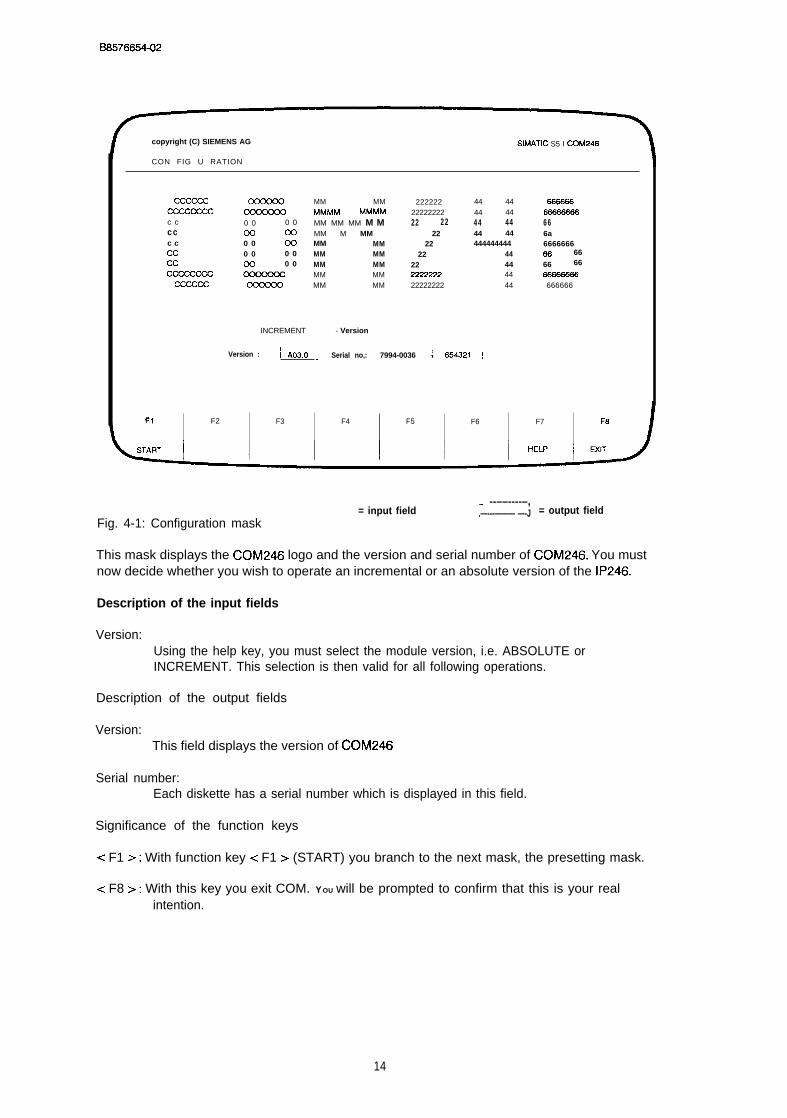
B6576654-02
copyright (C) SIEMENS AG SIMATIC S5 I CCIM246
CON FIG U RATION
Cccccc MM MM 222222 44 44 e66666Cu2Ccccc MMMM MMMM 22222222 44 44 W666666c c 0 0 0 0 MM MM MM M M 22 22 44 44 66cc co co MM M MM 22 44 44 6ac c 0 0 ccl MM MM 22 444444444 6666666cc 0 0 0 0 MM MM 22 44 Em 66cc m 0 0 MM MM 22 44 66 66
Cccccccc MM MM 22ZZ222 44 W666666Cccccc MM MM 22222222 44 666666
INCREMENT - Version
Version :-.
I A03.o ~ Serial no,: 7994-0036 ; 654321 :
F1 F2 F3 F4 F5 F6 F7 F8
= input field~ --––----–,
= output field.—---——— —-JFig. 4-1: Configuration mask
This mask displays the COM246 logo and the version and serial number of COM246. You mustnow decide whether you wish to operate an incremental or an absolute version of the IP246.
Description of the input fields
Version:Using the help key, you must select the module version, i.e. ABSOLUTE orINCREMENT. This selection is then valid for all following operations.
Description of the output fields
Version:This field displays the version of COM246
Serial number:Each diskette has a serial number which is displayed in this field.
Significance of the function keys
e F1 >: With function key c F1 > (START) you branch to the next mask, the presetting mask.
c F8 >: With this key you exit COM. YOU will be prompted to confirm that this is your realintention.
14
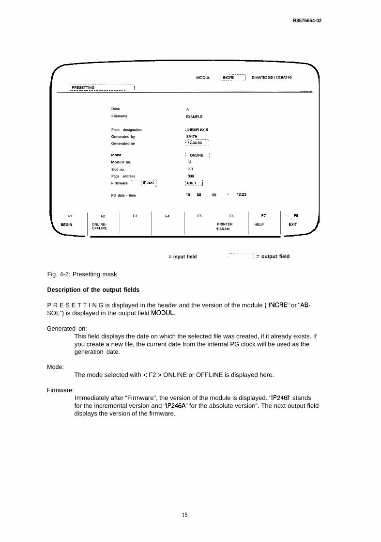
B8576654-02
-.. -- ———.—.— ... ... —.--. ——.[ PRESETTING
F1
L
BEGIN
Drive
Filename
Plant designation
Generated by
Generated on
Mcde
Mcdule no.
Slot no.
Page address,——————— —.<Firmware ~ IP2461 ;
PG date - time
F4
A
EXAMPLE
UNEARAXIS
SMITH..--. —--—-,! 12.06,89~————-— —-~
/ ONUNE j
11
001
Ooo
!A02.1 j- - - - - - -
!5 cm 89 “ 12:23
F5 F6 F7
PRINTER HELP‘PARAM.
F2 F3
J
F8
ONLINE- EXITOFFLINE
,.-------——= input field , I = output field
Fig. 4-2: Presetting mask
Description of the output fields
P R E S E T T I N G is displayed in the header and the version of the module (“INCRE” or “AB-SOL”) is displayed in the output field MODUL.
Generated on:This field displays the date on which the selected file was created, if it already exists. Ifyou create a new file, the current date from the internal PG clock will be used as thegeneration date.
Mode:The mode selected with < F2 > ONLINE or OFFLINE is displayed here.
Firmware:Immediately after “Firmware”, the version of the module is displayed. “IP2461” standsfor the incremental version and “IP246A” for the absolute version”. The next output fielddisplays the version of the firmware.
15
B8576654-02
Description of the input fields
Each module has several characteristics (SYSID), some of which cannot be changed and someof which can be selected. There are other characteristics which must be set, such as the modulenumber, and some which can be set. The latter are mainly of a documentary nature and are notchecked.
Drive:Here, you specify the drive in which the user data diskette is to be inserted. With thePG685, the data can, of course, be stored on the hard disk. In this case “B” must thenbe selected.
File name:The file name identifies the file in which the data blocks are stored (here, EXAMPLE),This allows you to assign different files to different projects or plant sections. Using thehelp key, it is possible to display ail the files on a current drive with the file type .246 forthe incremental version or .A46 for the absolute version. As you page through the filenames, the “plant designation”, “generated by” and “generated on” are updated.
Plant designation:In this field you can select a brief designation for the plant for which the data blocks areintended (here, LINEAR AXIS). This designation is written into the file header. This fieldmust be completed, otherwise the error message “inadmissible input” is displayed.
Generated by:As in the plant designation field, the name of the operator (here, SMITH) can be savedin the file. Once again this field must also be completed,
Module no.:This is a number between O and 99 which you can specify to distinguish betweenvarious positioning modules. A module number is also entered in the machine datarecords. If there are already machine data on the module, the module number enteredhere must be identical to that contained in the machine data records. This means thatthe module number can no longer be changed if one correct machine data recordalready exists on the module. (Only possible online.)
Slot no.:You can also assign this number as required, between O and 255. The number issimply for documentation. (Only possible online.)
Page address:The conditions for this are the same as for the slot number. The page address set onthe module can be read more easily at the PG than by reading the switch on thepositioning module itself (only possible online). Differences between the switch settingand the entry made here are not checked.
Date - time:The internal PG date and time are displayed here. if you modify anything in these fields,this is taken as a date and time change and the software clock of the PG is set to thesevalues.
16

B 8 5 7 6 6 5 4 - 0 2
Note:
After switching off the PG, this setting is lost. The hardware clock can only be set at thesystem level.
Significance of the function keys
< F1 >: With BEGIN, you branch to FUNCTION SELECTION and providing ONLINE is set, thepresets (module number, slot number, page address) are written to the module. Thesevalues are, however, only accepted by the module when either no correct machinedata are stored on the module or the module number is identical to the modulenumber in the machine data (= > “Functions, Reference Manual”, Section 3. I 9 “SYSIDInput”).
< F2 >: This key switches from OFFLINE to ONLINE and vice-versa. If you switch to ONLINE,the values on the module “module number”, “slot number”, “page number” and“firmware release” are read ( = > “Functions, Reference Manual”, Section 3.20 “ReadSYSID”) and displayed in the mask. OFFLINE, these fields are deleted. With theincremental version of the IP246 a correct actual value display in “test” is onlyguaranteed when the module does not start up again after selecting “online” (poweroff/on). Following a warm restart of the module < F1 > (BEGIN) must be pressed again.
< F6 >: Branch to the printer parameter mask. Declaration of control character sequences
< F7 >: Help key to select possible drives and file names contained in them.
< F8 >: With the EXIT key you return to the configuration mask,
17

B8576854-02
5 Function Selection
By pressing < F1 > (BEGIN) in the presetting mask, you branch to “function selection”.
The presets are displayed once again. The fields are, however, no longer output fields, i.e. youcannot change the displayed values. From this mask you branch to the individual functions. Ifyou terminate a function with the EXIT key you always jump back to this mask.
MOOUL : ~-k-fl-<--”i SIMATIC S5 / COM246. . . . . . . . . . . . . . . . . . . . . . . . . . .I FCT SELECTION ,
Drive
Filename
.— -—,[–A––;, -– .––– -–- - - ,I EXAMPLE. – - —-------- .1
Plant designation
Generated by
Generated on
Module no.
Slot no.
Page address
PG date time
ILINWR MIS 1.——— — - — - —-—------
; SMITH ;
h~-––. -Q8–9-8-9- ;
~.—.—.: ONLINE 1.——— —-—---
: 11 :- - - -..——.
1!?2.!~..—>~~-~
IA02.1 !L-----
F1 F2 F3 F4 F5 F6 F7 F.9
INPUT OUTPUT TEST TRANSFER DELETE INFOR- EXIT
,—..——...——-– input field I— = output field
Fig. 5-1: Basic mask
Significance of the function keys
< FI >: Branch to input of machine data/machining programs.
< F2 >: Branch to output of machine data/machining programs.
< F3 >: Branch to test mode.
< F4 >: Branch to transfer of machine data/machining programs on the individual media.
19

B8576654-02
< F5 >: Branch to deleting machine data/machining programs on the individual media
< F7 >: Branch to information (overview) of machine data/machining programs as they exist onthe individual media.
< F8 >: Return to the presetting mask.
20

B8576654-02
6 InputIf you press < F1 > (INPUT) in the basic mask (function selection) you branch to data input.
Here, you can generate machine data or machining programs and store them on the module,the PG or a data drive. You stipulate the destination device in this mask (function keys< F1 >... < F3 > ).
DATA BLWK MAOHINEOATA
,–_. _..BLOCK NO. DB ~fl~w_j
MODUL :! INCRE 1 SIMATIC S5 / COM246L——_. _.. ..l
! INPUT 1 DEVICE : ❑ LOCK : DB.--- _-_-. _.. ._ f_. ..f
“,F1’”, f?. , ‘.F~, . . F+. F?) Fe F7 F8
ODULE PG FD HELP EXIT
,---------~---__ --_-j = output field
Fig. 6-1: Block selection
Description of the output fields
I N P U T is displayed in the header. The version of the module (“INCRE” or “ABSOLi’) is display-ed in the output field MODUL. The other fields are still blank.
Description of the input fields
Data block:Select machine data or machining program. This field can be manipulated with thefunction key <F7> (HELP).
21
68576654-02
Block no.:You select the data block number under which the generated data are to be stored.The DB number can be a value between O and 255.
Description of the function keys
< F1 >: The destination device is the IP246 module. You branch immediately to the next mask,either to the first machine data or the first machining program mask.
< F2 >: The destination device is the programmer. YOU branch immediately to the next mask,either to the first machine data or the first machining program mask.
< F3 >: The destination device is the data drive entered in the configuration mask. You branchimmediately to the next mask, either to the first machine data or the first machiningprogram mask.
< F7 >: With the help key you can select the text “machine data” or “machining program” in the“data block” input field.
< F8 >: If you press the EXIT key you return to the basic menu (function selection).
6.1 Entering Machine Data
6.1.1 General Information about Machine Data
Before traversing movements can be executed, each axis requires the technical data of the drive.This information is known as machine data ( = > “Fundamentals of Positioning, ReferenceManual”, Section 4 “Machine Data and their Structure”),
When you input the machine data, the module checks that the data is consistent, If you make anerror, an error message is output and the program branches to the mask in which the incorrectvalue might be located. After correcting the value, the data record can once again be transferredto the module.
The data block numbers of the machine data for the two axes can be identical.
When deleting and entering a machine data record for the first time, the reference point of the in-cremental version and the home point of the absolute version need not necessarily be lost; thisdepends on the machine data in the new data record which have changed compared with theold record (= > “Functions, Reference Manual”, Section 3.17 “Machine Data Processing”). Zerooffsets and tool length offsets are, however, reset each time new machine data are input to themodule.
The individual machine data are only explained briefly here. For more detailed information aboutmachine data, refer to “Fundamentals of Positioning, Reference Manual”, Section 4 “MachineData and their Structure”.
22
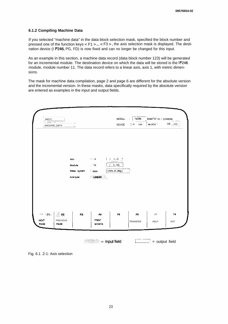
08576654-02
6.1.2 Compiling Machine Data
If you selected “machine data” in the data block selection mask, specified the block number andpressed one of the function keys < F1 >... c F3 >, the axis selection mask is displayed. The desti-nation device (I P246, PG, FD) is now fixed and can no longer be changed for this input.
As an example in this section, a machine data record (data block number 123) will be generatedfor an incremental module. The destination device on which the data will be stored is the IP246module, module number 11. The data record refers to a linear axis, axis 1, with metric dimen-sions.
The mask for machine data compilation, page 2 and page 6 are different for the absolute versionand the incremental version. In these masks, data specifically required by the absolute versionare entered as examples in the input and output fields.
,-——————.—————- ,.. -—- ——-.I INPUT MODUL : : INCRE ! SIMATIC S5 / COM246.-- ————_-———_— J..- ——. . --- . . . . . . . . . . . , - - - - . . - . ? .-- —--,
1
~ MACHINE OATA OEVICE: j 1P 246 ; BL~K : OB ; 123 ‘
L-––––– –-_–-–––––_.–-J. - - . . . . ,
‘ “ ””..F.l:. :.;” F~ ..~~ F4 F6 F6 F7 F8
NEXl PREVIOUS PRINl TRANSFER HELP EXIT
Axis :1 : ( 1...2) ?. . _____ ....,----.-...—.
Module : ’11 ! ( 0...99) ;.——-—— —----,--_— —________ .->Mee.s system : mm ~@m2~n,-d~~j___.-~
,___.. _-___l,1 ; = output field----------
Fig. 6.1 .2-1: Axis selection
23
B8576654-02
Description of the output fields
INPUT and M A C H I N E D A T A are displayed in the header. The module version (“INCRE” or“ABSOL”) is displayed in the MODUL field, the previously selected destination device is displayedin the DEVICE field and the previously selected DB no, in the BLOCK field,
Description of the input fields
Axis:In this field, you enter the number of the axis for which the machine data record is tobe created. The number can be either 1 or 2.
Module:In this field, you can enter the number of the module for which the machine datarecord is to be created. This is necessary, since several IP246 modules can be instal -Ied in a plant.
Meas, system:Here, you enter the required measuring system. mm stands for millimetres (basic uniturn), in for inches (basic unit 0.0001 in) and deg for degrees (basic unit 0,001 degrees).
Axis type:Using the help key < F7 > you can select either a rotary axis “ROUND” or linear axis“LINEAR”.
These values are used as output values for all machine data pages,
Significance of the function keys
< F1 > :
< F2 > :
< F4 > :< F6 > :
< F7 > :
< F8 > :
With function key < F1 > (NEXT PAGE) you branch to the first mask for machine datacompilation. This is distributed over six different pages.Select the previous machine data page. From this mask, you return to the last machinedata page if you press < F2 >,Output all the machine data on the printer.Store.all the machine data on the selected destination device. This is, however, onlypossible when all the input fields of all the pages have had values entered.Switchover the measuring system or axis type, providing the cursor is located in theappropriate input field.Return to the basic mask (function selection) after confirmation.
24
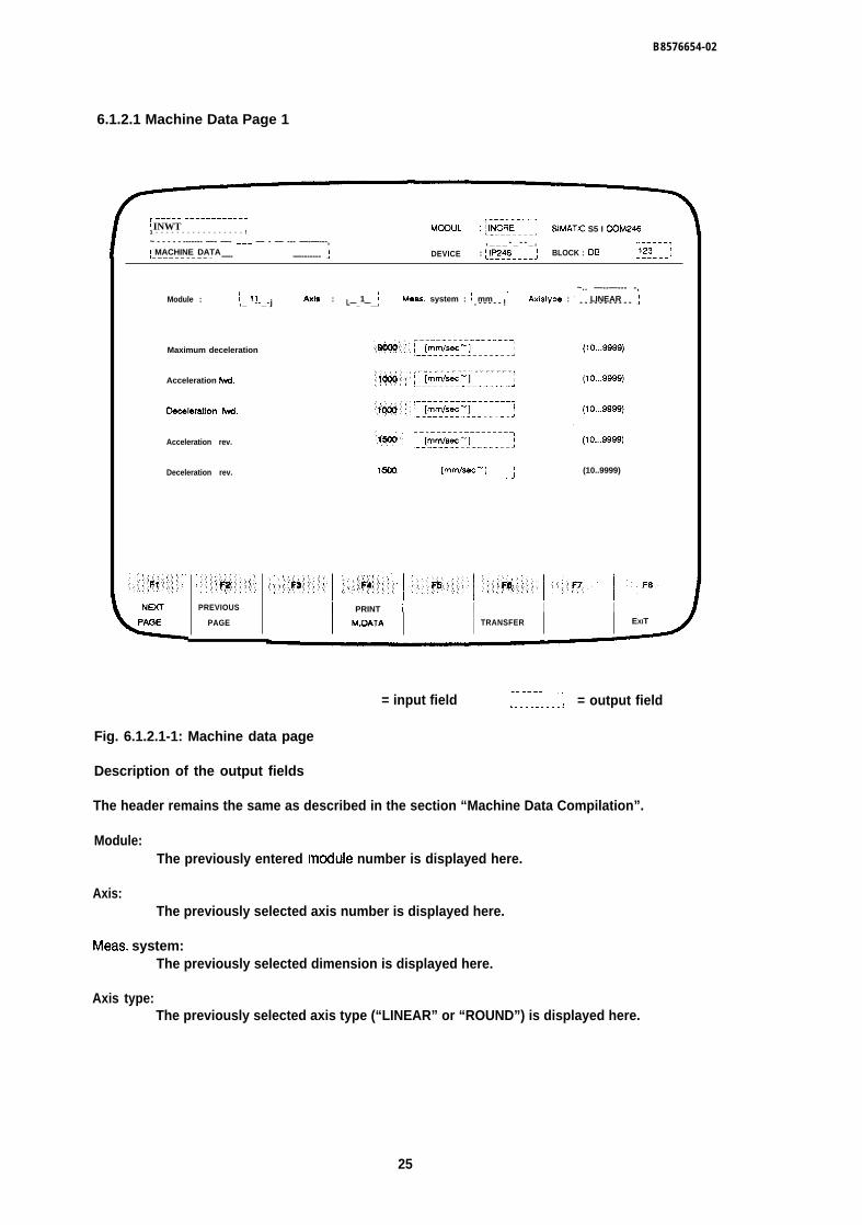
B8576654-02
6.1.2.1 Machine Data Page 1
~ ----– –––––––----–I INWT1 - - - - - - - - - - - - - - - - - ! MOOUL :[~”;ii---; SIMATIC S5 I COM246~ - - - - - ------- —- —- ——— — - — --- —-—---,I MACHINE DATA
, _ _ _ - _ - - _ T~––––-,
,–----------- —- —————– ——– —------- -! DEVICE : ~lf2fQ–---; BLOCK : DE ~1::--- :
------I
Module :~.. —--—--- -,
: 11 Axis : ! 1 I Meas. system : ~ mm,_ --_-j L—_ —__, Axistype : I LINEAR ;. - - - - - ! - - - - - - - - - - -
Maximum deceleration
Acceleration fwd.
OOceleratlon fwd.
Acceleration rev.
Deceleration rev.
G-PREVIOUS
PAGE
(10,,.9999)
lwm ; [mmlsec-] } (10..9999)-J
I PRINT / I I IM.OATA TRANSFER EXIT
= input field__ ._ .. .._-. . . . . . . . . . . = output field
Fig. 6.1.2.1-1: Machine data page
Description of the output fields
The header remains the same as described in the section “Machine Data Compilation”.
Module:The previously entered tnodule number is displayed here.
Axis:The previously selected axis number is displayed here.
Meas. system:The previously selected dimension is displayed here.
Axis type:The previously selected axis type (“LINEAR” or “ROUND”) is displayed here.
25
B8576654-02
Description of the input fields
Maximum deceleration:The maximum deceleration when hardware limit switches are tripped or when an exter-nal STOP is received, can be selected between 10...9999.
Acceleration fwd.:Acceleration values between 10..9999 for any acceleration in a forward direction
Deceleration fwd.:Deceleration values between 10...9999 for any deceleration in a forward direction
Acceleration rev.:Acceleration values between 10...9999 for any acceleration in the reverse direction
Deceleration rev.:Deceleration values between 10...9999 for any deceleration in the reverse direction
Significance of the function keys
< F1 >: Select the next machine data page.< F2 >: Select the previous machine data page,< F4 >: Print out all machine data,< F6 >: Store all machine data on the destination device.< F8 > : Return to the basic mask without storing the data.
26
B8576654-02
6.1.2. Machine Data Page 2 (Incremental Version)
‘FzF-----------; MOOUL : ! INCRE \ SIMATIC S5 / COM246!----- . __ -- _-__-__,,- _____ -- _ - ______ ----------------/ ,. . . ,
I MACHINE OATA 1 DEVICE : [-l_y~w. __; BLOCK: OS :!{3--- ;,------------ _- - - - - - - _- -_____ - - -J
- - - . - . ,~_ .-__,Module :
,______ ~_. ---. . . . . . .
1 11 Axis : , - - - _ - j11 Mea% $yslem : i mm I.-----J Axistypa : iLlNEAR.____. J .____ .--. ..J
Pulse waluab-1 .:;::~j~j~g;j,,~.~::” ~,, * , ~,
FbOlulion;.’j;:;jg;: ,:~::.:: [mm/lCOO pls ] (0.1...99.9 )
Gain factor “’’’ ’’’.*i: 8: “ [1/90.] (0.1 ...99.9 )
, - - - - - - - - - -
Sacklfuh comp. value ..:,:;;::~. ~ 1 [mml I- - - - - - - - - - - - (omoO,..64.999 )
, - . . .----..,
Standstill monitor q w:. I [mm] ‘, _ - _____...’ (0. C.91...69S9)9)
, - _ --_._.._,
Max. following error ~~•. *, *. 1 [mm] 1: .’; ! __________ (o.wl...999999 )
When follou+ng error - W.W9, follwing error Is disabled
,i:.::,:::;~i:f::i::::::::’::!!::~:::;;.{:;i~;;::’ .:: ::,::.:k$,::::;i’;i: .:’.,. ‘.:;:$$:;::!::.:::’”’ .:j;;.:.:;f5.:::.,;;::., ‘,:, . . . ..$I$::.:”:”;’... .: ~r” FB
NEXT PREvIOUS PRINT
, - ____-_--,., ~~~¿H• = input field I_._. _---.; = outPut ‘ield
Fig. 6.1 .2.2-1: Machine data page 2
Description of the output fiefds
The header remains as described in the section “Machine Data Compilation”.
Module, axis, meas. system, axis type: see machine data page 1.
Description of the input fields
Pulse evaluation:Single, double or quadruple evaluation of the pulses from the incremental positionencoder can be selected.
Resolution:Travel distance related to 1000 pulses from the position encoder. The value enteredhere has no significance. A value within the specified limits must, however, be entered.The actual resolution is assigned using the values “pulses/revolution” and “distance/re-volution”. COM changes this input field automatically when you page through the indivi-dual machine data pages.
27
B8576654-02
Note:
With the incremental version, from firmware version 2,1, the values pulse/revolution anddistance/revolution are taken from page 6 of the machine data. If these values result in, forexample, a resolution of 100.0, then the value 00,0 will be entered in the resolution field ofthe machine data. This is, however, an illegal value, and it would be impossible to exit themask. For this reason, C0M246 enters a value within the permitted limits, The calculatedvalue is then supplied by the firmware.
Gain factor:Gain factor (k”) of the position controller in units l/see, The permitted limits are0.1...99.9. Depending on the plant and the other machine data (e.g. resolution ormaximum speed) not all of these values are generally permitted,
Backlash comp. value:This value is added to the distance to be travelled whenever the axis changes direc-tion. This allows backlash outside the control loop (play in the drive) to be compensa-ted, The backlash compensation is only effective when it is certain that there is nolonger play between the drive and the carriage, With a reference point approach, thismay be the case immediately following the reference point approach. Otherwise youmust make sure this play is taken up yourself,
Standstill monitor:The maximum difference between the setpoint and actual position value when the axisis at rest and the position controller is active. This value must be greater than O andless than the maximum following error,
Max. following error:The maximum difference between the setpoint and actual position value when closedloop control is active. The maximum following error must be greater than or equal tothe standstill monitor value. Monitoring of the following error can be suppressed by en-tering the maximum value (99,999) in the field,
Significance of the function keys
< F1 >: Select the next machine data page,< F2 >: Select the previous machine data page.< F4 >: Print out all machine data.< F6 >: Store all machine data on the destination device,< F8 >: Return to the basic mask without storing the data,
28
B8576654-02
6.1.2.3 Machine Data Page 2 (Absolute Version)
This machine data page for the absolute version differs from the page for the incremental version.
,------------------ 11 INPUT ,
~_–––, - - - ,MODUL ,----------L----- __ -- ________! :1 ABSOL SIMATIC S5 I COM246
~------------------------------- ,I MACHINE DATA
~–_–-–-__, .,
L - - - - - - - - - - - - - - - - - - - - - - - - - - - - - - . DEVICE :;_!~ff_---; BLCCK : DB @-- ;
-— —-_TModule : } 22 ~.—— —--
Gain factor
Backlash comp. value
standstill monitor
Max. following error
Axis : r---j Meas. system : ~ mm j histyp : ~ LINEARI
!----- ... —-- . . . . . . . . . . . J
,___ —_.-__.,o 100 ~m-ml-. --. j (0.001...64.999)
When following error = 99.S9!3, folldng error Is di6ablad
,—— —_.._..,= input f ie ld L- - - - _I_.-I = outPut field
Fig. 6.1 .2.3-1: Machine data page 2
Description of the output fields
The header remains as described in section “Machine Data Compilation”.
Module, axis, meas. system, axis type: see Machine Data Page 1.
Description of the input fields
Gain factor:Gain (kv) factor of the position controller in units l/see. The permitted limits are0.1...99.9. Depending on the plant and the other machine data (e.g. resolution ormaximum speed) not all of these values are generally permitted.
29
B8576654-02
Backlash comp. value:This value is added to the distance to be travel led whenever the axis changes direc-tion. This allows backlash outside the control loop (play in the drive) to be compensa-ted, The backlash compensation is only effective when it is certain that there is nolonger play between the drive and the carriage. You must make sure this play is takenup yourself.
Standstill monitor:The maximum difference between the setpoint and actual position value when the axisis at rest and the position controller is active. This value must be greater than O andless than the maximum following error.
Max. following error:The maximum difference between the setpoint and actual position value when closedloop control is active. The maximum following error must be greater than or equal tothe standstill monitor value. Monitoring of the following error can be suppressed by en-tering the maximum value (99,999) in the field,
Significance of the function keys
< F1 >: Select the next machine data page.< F2 >: Select the previous machine data page.< F4 > : Print out all machine data.c F6 > : Store all machine data on the destination device.< F8 >: Return to the basic mask without storing the data
30
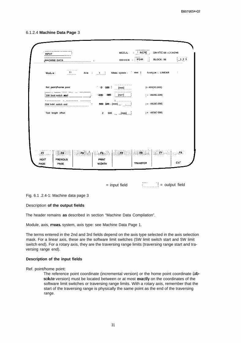
B8576654-02
6.1.2.4 Machine Data Page 3
, -----------------~ INPUT I MODUL : [ INCRE i SIMATIC S5 I COM246
I - — - . . . — . . /
, –—————— ~--------- . . . . . . 1
‘ MACHINE DATA 7L - - - - - - - - - - - - - - - - - - - - - - - - - - - - - - - I DEVICE : ~-1~~~~--_; BLOCK: 06 ( 1 2 3,— -.. J
. . . . . .Mcdule : ~::–––j Axis : ~-j---j Meas. system : ~ mm ~ Axlstype : I LINEAR I
. . . . . . . . . .Ref. peinVhOme point ‘“ O‘ C@ I [mm] I (+. 400(X3,000). . . . . . . . . . .,--. .. ———. ----- —.. ... —-.-—---- - - - - - - - - - - -
I\ SW Iimil switch start 1: “~!x? m ~--by--.l (+. 4COW.000).—————— ——-———— ———-———— —-—----J
~ – – – – – – - – – – _ – - – – – – – – - - - - - - - - - i __ . . . . . . . .
/SW Iimi! switch end ~ ; soo (MO I [mm] I (+. 4wc0.mo)- - - - - - - - - - - - - - - - - - - - - - - - - - - - - - .— — __-.....,
Tool length offset 2 S00 I [mm] I (+. 4oaxlooo),— — -—-.....,
;@+: ‘ I ., ‘ ‘.’.
= input field. . . . . . . . . .I ~ = output field. . . . . . . . . . .
Fig. 6.1 .2.4-1: Machine data page 3
Description of the output fields
The header remains as described in section “Machine Data Compilation”.
Module, axis, meas. system, axis type: see Machine Data Page 1.
The terms entered in the 2nd and 3rd fields depend on the axis type selected in the axis selectionmask. For a linear axis, these are the software limit switches (SW limit switch start and SW limitswitch end). For a rotary axis, they are the traversing range limits (traversing range start and tra-versing range end).
Description of the input fields
Ref. point/home point:The reference point coordinate (incremental version) or the home point coordinate (ab-soiute version) must be located between or at most exactiy on the coordinates of thesoftware limit switches or traversing range limits. With a rotary axis, remember that thestart of the traversing range is physically the same point as the end of the traversingrange.
31
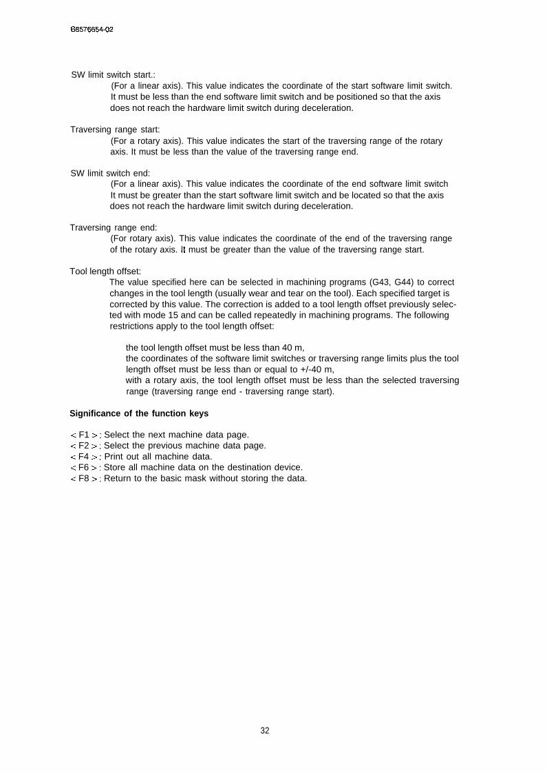
08576654-02
SW limit switch start.:(For a linear axis). This value indicates the coordinate of the start software limit switch.It must be less than the end software limit switch and be positioned so that the axisdoes not reach the hardware limit switch during deceleration.
Traversing range start:(For a rotary axis). This value indicates the start of the traversing range of the rotaryaxis. It must be less than the value of the traversing range end.
SW limit switch end:(For a linear axis). This value indicates the coordinate of the end software limit switchIt must be greater than the start software limit switch and be located so that the axisdoes not reach the hardware limit switch during deceleration.
Traversing range end:(For rotary axis). This value indicates the coordinate of the end of the traversing rangeof the rotary axis. [t must be greater than the value of the traversing range start.
Tool length offset:The value specified here can be selected in machining programs (G43, G44) to correctchanges in the tool length (usually wear and tear on the tool). Each specified target iscorrected by this value. The correction is added to a tool length offset previously selec-ted with mode 15 and can be called repeatedly in machining programs. The followingrestrictions apply to the tool length offset:
the tool length offset must be less than 40 m,the coordinates of the software limit switches or traversing range limits plus the toollength offset must be less than or equal to +/-40 m,with a rotary axis, the tool length offset must be less than the selected traversingrange (traversing range end - traversing range start).
Significance of the function keys
< F1 >: Select the next machine data page.< F2 >: Select the previous machine data page.c F4 >: Print out all machine data.< F6 >: Store all machine data on the destination device.< F8 >: Return to the basic mask without storing the data.
32
B8576654-02
6.1.2.5 Machine Data Page 4
, —- ————— —--____ -_-,~ INPUT
I
___ - . . __ - ....._..!
; .__----- _--. ... .__. __. .. —------, _ _ _ _ . . . _ _ , , - - - - -
IMACHINEDATA,
I DEVICE :~_[P:~g__--: BLOCK : D13 ~123 ;,___-_-- __-- _-_- ———— — . _ . ._ .. _____
[___ .., . - _ . . . , . . . . . . . . . . . .
Module : , 11 J ~i,: ~--l---jMeas. s y s t e m : !mm j-— —-. Axistype: ILINEAR J. . . . . . . . . .
Zero point offset 1 i~..* ;-;;;;- j (+. 40000.000)
, - . - - - - - - – -
Zero point 0ff5et 2 Z5 .000 ~ [mm] ~-, ( + 40000.000)
.— - - - - - -—
Zero point offset 3 ‘: a 2@ I [mm] ~. . . . . . . . . . . (+- 40000.000)
Zero point offset 4- 7
75 C@ / [mm] : (+. 40WXY,WO)
61’”
NEXT PREVIOUS PRIN-T
= input field :-__ ---_i_i = output field
Fig. 6.1.2.5-1: Machine data page 4
Description of the output fields
The header remains as described in section “Machine Data Compilation”.
Module, axis, meas. system, axis type: see Machine Data Page 1.
Description of the input fields
Zero point offsets 1...4:The values of the four zero point offsets are independent from each other and can becalled alternatively in machining programs using G54...G57. They are added to offsetsexecuted with the modes “zero point offset absolute/relative” (BA 12, BA 13). The rangeof values of the four offsets is +/-40 m. In addition to this, the coordinates of the soft-ware limit switches or traversing range limits must not exceed +/- 40 m following thezero point offset.
33

BS5766S4-02
Significance of the function keys
< F1 >: Select the next machine data page.-= F2>: Select the previous machine data page.< F4 > : Print out all machine data.< F6 >: Store all machine data on the destination device.< F8 > : Return to the basic mask without storing the data.
6.1.2.6 Machine Data Page 5
,------ __---------,I INPUTL_-–-–-–_---- _-_-_i MODUL :[jNCRE~~~: SIMATIC S5 / COM246,-_---— ----- ___---- _____ --___ ---T ,I MACHINE DATA
. . . . . .( D E V I C E :~j~~~6jjj~j BLOCK : DB ! 1 2 3L- - - - - - —-- - - - - - - - - - _ - -____ -____— ._ —----
.- —---,Module :
-- ——-q . . . . . . . .; 11 j Ads : I 1 ; Meas, system : I mm ; Axistype : ~L!NE~5-----l
, – - - - - - – – - . - ,Maximum spmd m ~-mm!m:nJ-..; (1 ,., 65CCCJ)
,— ------ —--->JCG s- 1 fwd. W@o ~-_[~~@!nJ---; (1 ,,, 65CC+J)
____________JOG SfMOd 1 rev. tyxlo / [mn-dmin] \ (1 65000)- - - - - - - - - - - -
____________JOG speed 2 fwd. .,..’;:I,i~*::?:?:’ ~ [ m m / m I n ] j ( 1 65CCO)- - - - - - - - - - - -
, . - . -___ - - -_ n
JOG sped 2 rw, ‘::::~~:, /--@g@j___l: ,.,. (1 ,,. 65000)
Increnwnlal sped .,:::.!: ,::~~: ;--[;-;,-mi;~--;1 ( 1 65CC+J)
,;:;::,::jj~~.~’gj;~[~’:;;;;i:’:; :,;’~:~;;’;~~;.l:j..~~’j~~~::: .::::;:;::jj~::j::j;;~;:::: \:’,::;:;;;;lF4;’::::,~:.;:::: ,:,::,.::::*:.. .:,:. ,,;:::::;::ye....,,, ,:,,:,:::,,,:::..:,.:. .Y F8
NWT PI+Ewous PRINT
,__________( ~ = output fieldI____ --__-d
Fig. 6.1 .2.6-1: Machine data page 5
Description of the output fields
The header remains as described in section “Machine Data Compilation”.
Module, axis, meas. system, axis type: see Machine Data Page 1.
34
B8576654-02
Description of the input fields
Maximum speed:This value specifies the speed with which the axis traverses when 10 V are output atthe power unit.
Example
Rated rpm of the motor: N = 2000 rpm; “distance per encoder revolution” : 10 mm/rev
This results in a maximum speed as follows:
Vmax = 2000 rpm 10 mm/rev = 20000 mm/min
The value “distance per encoder revolution” includes all transmissions (gearing)between the position encoder and the axis.
JOG speed 1 fwd.:Value for JOG speed 1 in the forward direction. This value must be less than or equalto the maximum speed and greater than 1.
JOG speed 1 rev.:Value for JOG speed 1 in the reverse direction. This value must be less than or equal tothe maximum speed and greater than 1.
JOG speed 2 fwd.:Value for JOG speed 2 in the forward direction. This value must be less than or equalto the maximum speed and greater than 1.
JOG speed 2 rev.:Value for JOG speed 2 in the reverse direction. This value must be less than or equal tothe maximum speed and greater than 1.
Incremental speed:Value for the speed for incremental approach (BA 6 and BA 7). This value must be lessthan or equal to the maximum speed and greater than 1.
Significance of the function keys
< F1 >: Select the next machine data page.c F2 >: Select the previous machine data page.< F4 >: Print out all machine data.< F6 >: Store all machine data on the destination device,< F8 >: Return to the basic mask without storing the data,
35
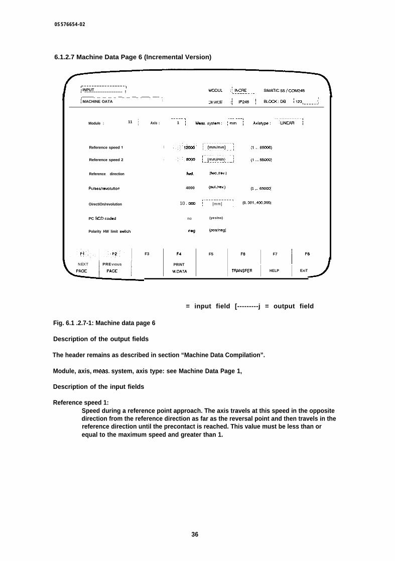
0S576654-02
6.1.2.7 Machine Data Page 6 (Incremental Version)
,–––––––––––––––. -1I INPUTL ––––––––––––––––– ! MODUL :~~~~{{E---j SIMATIC S5 I COM246
,———. ... ... ... .. —.. ... —.. .——. —-- . 1\ MACHINE OATA I DEYICE :~ IP246 ~ BLDCK:D9 ~123 ‘,—————,
Module : ~ 11 j
Reference speed i
Reference speed 2
Reference direction
Pulseslrevolution
OirectiOn/revolution
PC SCO-coded
Polarity HW limit switch
NEXT PREVIOUS
,————— ~ ..- ———, ,. —————————,Axis : ; 1 ~ Meassy&em: ;mm j Axistype: ILINWR ;-———.....——
f’.+d. (fwl.lrev.)
4000 (pul./rev.) (1 ,.. 650CXl)
,---––-----–,10 .000 ~ [mm] j (0. CQ1..4OO.OOO)
no (yes/no)
w (p.x.heg)
F3 F4 F5
M.DATA I
FE I F7
1
F8
TFIANSFER I HELP I EXIT
= input field [---------j = output field
Fig. 6.1 .2.7-1: Machine data page 6
Description of the output fields
The header remains as described in section “Machine Data Compilation”.
Module, axis, meas. system, axis type: see Machine Data Page 1,
Description of the input fields
Reference speed 1:Speed during a reference point approach. The axis travels at this speed in the oppositedirection from the reference direction as far as the reversal point and then travels in thereference direction until the precontact is reached. This value must be less than orequal to the maximum speed and greater than 1.
36

B 8 5 7 6 6 5 4 - 0 2
Reference speed 2:Speed during the reference point approach. After reaching the precontact in the refe-rence direction, the axis travels at this speed as far as the reference point (zero markerof the encoder). It must be:
less than or equal to the reference point speed 1,less than or equal to the maximum speed andgreater than 1.
Reference direction:Direction (forward, reverse), in which the axis moves from the precontact to the zeromarker during reference point approach.
Pulses/revolution:This field specifies how many signal edges of the two position encoder signals (A andB) are evaluated. In single evaluation, the number of signal edges to be evaluated isthe same as the number of pulses per encoder revolution. In double evaluation, this istwice the number and in quadruple evaluation four times the number of pulses perencoder revolution. The possible range is from to 65000.
Distance/revolution:(Note: “direction” is an error in the software which will be corrected in the next version).In these two fields (numbers and decimal places) the distance per encoder revolutionis specified. The range of values is from 0,001 to 400.000. This value includes all trans-missions (gearing) between the position encoder and the axis.
The two values “pulses/revolution” and “distance/revolution” produce the resolution (distan-ce/pulses).
PC BCD-coded:If you enter “yes” in this field (help key < F7 > ), all coordinates (targets, travel incre-ments, zero point offsets and tool length offsets) transferred from the PC are interpre-ted by the IP246 in BCD format. The range of values in BCD format is limited to ~/-9999999.
Polarity HW limit switch:In this field you specify the polarity of the hardware limit switch. “Pos.” means positiveedge when the limit switch is triggered (normally open contact) and ‘[neg. ” means nega-tive edge when the limit switch is triggered (normally closed contact).
Significance of the function keys
< F1 >: Select the next machine data page.< F2 >: Select the previous machine data page.< F4 >: Print out all machine data.< F6 >: Store all machine data on the destination device.< F8 >: Return to the basic mask without storing the data.
37
B8576654-02
6.1.2.8 Machine Data Page 6 (Absolute Version)
This page of machine data for the absolute version differs from the page for the incremental ver-sion.
,--------I INPuT I!—————— ——--————— —_! M O O U L :@--~ SIMATIC S5 / COM246,__-_. _._ —_-- _—————— ——-.———————. l
! MACHINE DATA ( 1,–-—--– ––– —–—– ——-–––––––-––––––– -f DEVICE :~-!yyg–––_~ BLOCK : D9 [123,————— -
,- —— -—, ... ——. ,I
-.__ ——————TModule : / 22 / Axis : :1 Meas. system : !-MM--J Axislyp-e : ~~lN-~~-----j!—---—J
Encoder:
Numtmr of revolutions 512 (rev.)
Number of stepslrew 1024 (step/rev.)
, . - . - . . . . .1Directionlrevolution 2 !56u ~ [mm] ;
PC BCD-coded no (yes/no)
Polarity HW limit witch n~ (poslneg)
F1 F2 F3 F4 F5
NEXT PREVIOUS PRINT
(1 ,,, 65cC6)
(2,., 65CC13)
(o.ool..4@Yw3o)
F6 F7 I F8
= input field ~---------j = output field
Fig. 6.1 .2.8-1: Machine data page 6 (abs)
Description of the output fields
The header remains as described in section “Machine Data Compilation”.
Module, axis, meas. system, axis type: see Machine Data Page 1.
Description of the input fields
Number of revolutions:This field specifies how many revolutions the absolute position encoder requires toexceed its total range once. The range of values is from 1 (single turn) to 65000 (multi-turn).
38
08576654-02
Number of steps/rev.:This field specifies how many steps the position encoder has per revolution. The rangeof values is from 2 to 65000. If values are specified which are not equal to a power of 2,it is assumed that you are using an absolute position encoder with the Gray excess Xcode.
The product of the number of revolutions and the number of steps/revolution k the total numberof steps of the absolute position encoder. The total number of steps is limited to 220.
Distance/revolution:(Note: “direction” is an error in the software which will be corrected in the next version).In these two fields (numbers and decimal places) the distance per encoder revolutionis specified. The range of values is from 0.001 to 400,000, This value includes all trans-missions (gearing) between the position encoder and the axis.
The two values “pulses/revolution” and “distance/revolution” produce the resolution (distancc/pulses).
PC BCD-coded:If you enter “yes” in this field (help key < F7 > ), all coordinates (targets, travel incre-ments, zero point offsets and tool length offsets) transferred from the PC are interpre-ted by the IP246 in BCD format, The range of values in BCD format is limited to I-;-9999999.
Polarity HW limit switch:In this field you specify the polarity of the hardware limit switch. “Pos.” means positiveedge when the limit switch is triggered (normally open contact) and “neg. ” means nega-tive edge when the limit switch is triggered (normally closed contact).
Significance of the function keys
< F1 >: Select the next machine data page.< F2 >: Select the previous machine data page.< F4 >: Print out all machine data.< F6 >: Store all machine data on the destination device,< F8 >: Return to the basic mask without storing the data.
6.1.3 Print Machine Data
The data (DB number) selected using the functions “input” or “output” of machine data can beprinted out using function key < F4 > (PRINT M. DATA). The data are formatted in a fixed frame-work.
A header is printed out at the start of each machine data page and a title block (footer) at the end
39
B8576654-02
[
—————
MACHINE DATA Source DB no. Axis Module Meas system~
LINEAR IP246 123 1I
11 mm
Maximum deceleration : 9000 [mm/see-] (10.9999)
I Acceleration fwd. 1000 [mm/see-] (10...9999)
Deceleration fwd, 1000 [mm/see-] (10...9999)
Acceleration rev. 1500 [ m m / s e e - ] ( 1 0 9 9 9 9 )
n . . . ,“ {
II
“ Printout
/ .
,, header
,..
Incremental speed 17500 [mm/min] (10...9999)
I..-.. T-–.—-
7I
SIEMENS AGI
PRINTOUT i Date: 16,09.89
SIMATIC S5 MACHINE DATA AXIS 1
C0M246 - IP246 LINEAR AXS SMITH L--]Fig. 6.1 .3-1: Machine data printout
The following information is supplied in the header:the machine data are for a linear axis,the source device (FD, PG or IP246) from which they were read,the DB number under which they are stored,the axis and module for which they are intended andthe measuring system (mm, in or deg.) of the machine data.
Title block
The title block is explained in the machine data printout mask,
40
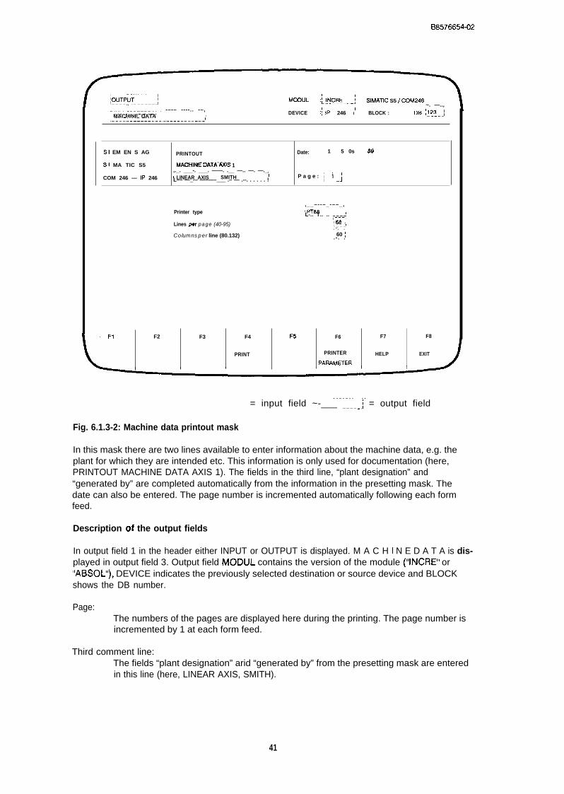
B8576654-02
,–––-_––––_––]omy~-----–] ~.–-––-–-,MODUL :[~N12~E–--j SIMATIC S5 t COM246
~. —..,I~–-. ---––----. -–-– ----.. -–,
, DEVICE :{ 1P 246 I DB !~~~-jI MACHINE DATA BLOCK :<-_.–-–– –––_.–. -–––––_-–––_l
S1 EM EN S AG PRINTOUT Date: 1 5 0s se
S! MA TIC S5 MAOHINEDATAAXfS 1,._. ___-. ___. ——. .__ —.. —. —._ l
COM 246 — 1P 246 I LINEAR AXIS SMITH ! P a g e : ~--r-lL–– —_-– —–—–___ .– — .--. . . . . . ! .1
Printer type,__–--–_-––_,IPT88 IL-.. T.. .. T–.–.-:l
Lines per page (40-95) ,~ ,L.–J.- . .
Columns per line (80.132) : 60 /. - . .
F1 F2 F3 F4 F5 F6 F7 F8
PRINT PRINTER HELP EXIT
PAFLAMHER
. . . . . . . . . . .= input field ~-___ ----_j = output field
Fig. 6.1.3-2: Machine data printout mask
In this mask there are two lines available to enter information about the machine data, e.g. theplant for which they are intended etc. This information is only used for documentation (here,PRINTOUT MACHINE DATA AXIS 1). The fields in the third line, “plant designation” and“generated by” are completed automatically from the information in the presetting mask. Thedate can also be entered. The page number is incremented automatically following each formfeed.
Description of the output fields
In output field 1 in the header either INPUT or OUTPUT is displayed. M A C H I N E D A T A is dis-played in output field 3. Output field MODUL contains the version of the module (“INCRE” or“ABSOL”), DEVICE indicates the previously selected destination or source device and BLOCKshows the DB number.
Page:The numbers of the pages are displayed here during the printing. The page number isincremented by 1 at each form feed.
Third comment line:The fields “plant designation” arid “generated by” from the presetting mask are enteredin this line (here, LINEAR AXIS, SMITH).
41

B8576654-02
Printer type:This field displays the printer selected in the printer parameter mask, The default is theSiemens PT88 printer,
Lines per page:The number of lines per page selected in the printer parameter mask is displayed. Thedefault is 68 lines per page.
Columns per line:The number of columns per line selected in the printer parameter mask is displayedhere. The default is 80 columns per line.
If you have not yet printed out or not yet set the printer parameters, branch to the “printer para-meter mask” with < F6 > (PRINTER PARAMETER). Refer also to Section 6,1,4 “Assigning PrinterParameters”.
Description of the input fields
Comment:In two lines of the title block you can enter a comment about the machine data to beprinted out. This comment is then printed out as a title block on each page.
Date:In these three input fields you can enter the date on which the machine data werecreated, This date is also printed out on each page.
Significance of the function keys
< F4 >: The printout is started with this function key.< F6 >: This function key branches to the printer parameter mask,< F7 >: Help key: no function.< F8 >: Exit the print option without printing out,
6.1.4 Assigning Printer Parameters
From the presetting mask and from the mask for printing machine data, you can branch to theprinter parameter mask by pressing < F6> (PRINTER PARAMETER). Here, you can select theSiemens printers PT80 and PT88 or other printers using the IBM or EPSON mode. The values forthe number of lines per page (default 68) and the number of columns per line (default 80) can bechanged. You can also adapt the control characters for print type and character set to anyprinter. The control characters must be entered in ASCII code without gaps or separators. Amaximum of 5 ASCII characters can be entered. If a control character sequence is less than 5characters, the sequence must be completed with ASCII NIL characters,
At present, only the parameters for print type 2 can be used,
42
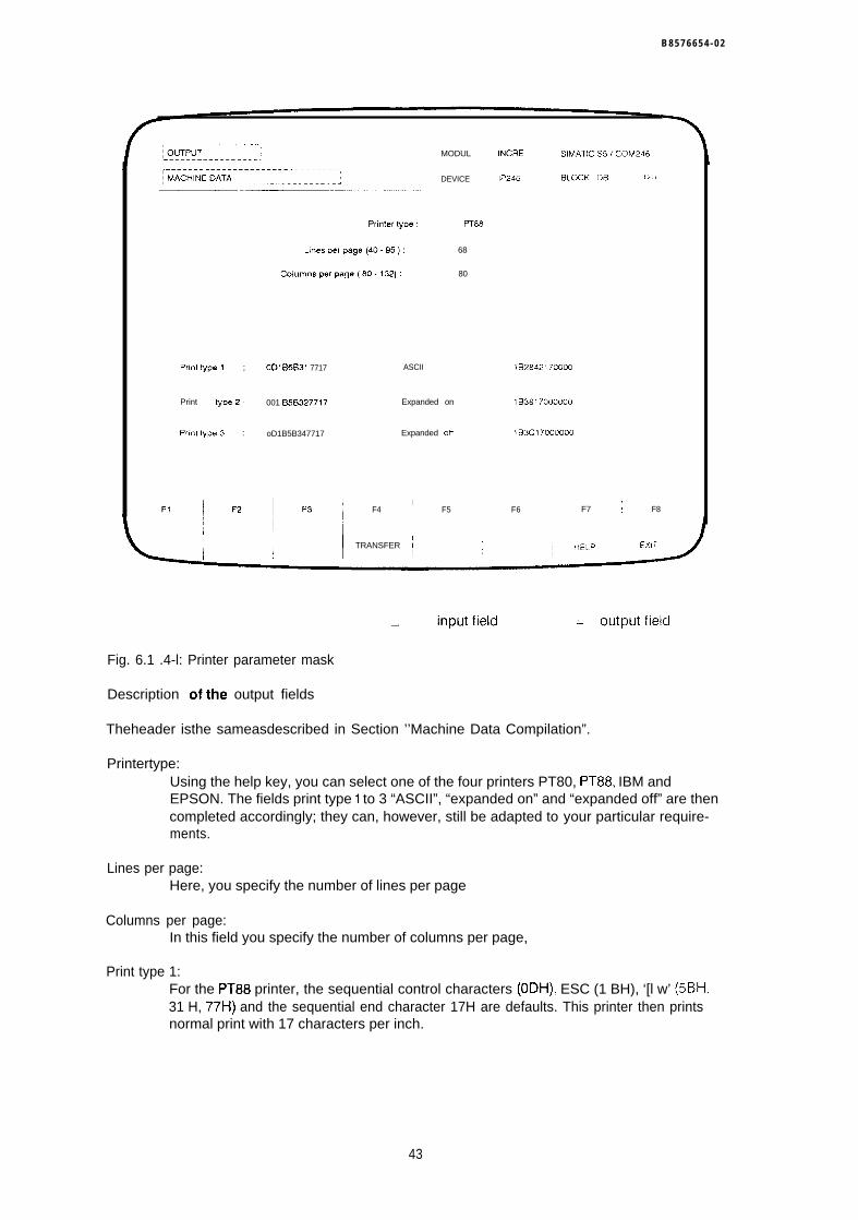
B 8 5 7 6 6 5 4 - 0 2
Prin[typel ; ODI &5B31 7717
Print type2 : 001 B5B327717
Pr(nftype3 : oD1B5B347717
ASCII
MODUL
DEVICE
PT88
Expanded on
Expanded oli
IF4 F5
68
80
INCRE SlMATlCS5/COM246
IP246 BLOCK:I)B 1/.
1B2842170000
1B3817000000
1B3C17000000
F6 F7 ; F8
I TRANSFER !
= inputfield ‘- -“ = OIJtplJtfleld
Fig. 6.1 .4-l: Printer parameter mask
Description ofthe output fields
Theheader isthe sameasdescribed in Section ’’Machine Data Compilation”.
Printertype:Using the help key, you can select one of the four printers PT80, PT88, IBM andEPSON. The fields print type 1 to 3 “ASCII”, “expanded on” and “expanded off” are thencompleted accordingly; they can, however, still be adapted to your particular require-ments.
Lines per page:Here, you specify the number of lines per page
Columns per page:In this field you specify the number of columns per page,
Print type 1:For the PT88 printer, the sequential control characters (ODH), ESC (1 BH), ‘[l w’ (5BH,31 H, 77H) and the sequential end character 17H are defaults. This printer then printsnormal print with 17 characters per inch.
43
B8576654-02
Print type 2:For the PT88 printer, the sequential control characters (ODH), ESC (1 BH), ‘[2w’ (5BH,32H, 77H) and the sequential end character 17H are defaults. This printer then printscondensed print with 12 characters per inch.
Print type 3:For the PT88 printer, the sequential control characters (ODH), ESC (1 BH), ‘[4w’ (5BH,34H, 77H) and the sequential end character 17H are defaults, This printer then printssuper-condensed print with 10 characters per inch.
ASCII:For the PT88 printer, the sequential control characters ESC (1 BH), ‘(B’ (28H, 42H) andthe sequential end character 17H are defaults, This printer then prints with the ASCIIcharacter set.
Expanded on:For the PT88 printer, the sequential control characters ESC (1 BH), ‘8’ (38H) and the se-quential end character 17H are defaults, Expanded print is then set on this printer.Each character is then printed in double width.
Expanded off:For the PT88 printer, the sequential control characters ESC (1 BH), ‘ < (3CH) and thesequential end character 17H are defaults, This switches off expanded print on thisprinter. Each character is then once again printed in normal width.
For IBM or EPSON printers please refer to the control characters in the appropriate manual
6.2 Entering Machining Programs
6.2.1 General Information about Machining Programs
The structure of the machining program generally corresponds to a subset of the representationdescribed in DIN 66025. The programs consist of a sequence of ASCII characters with amaximum length of 1023 characters.
Machining programs are packaged by C0M246 in data blocks in keeping with the STEP 5 repre-sentation. The blocks are distinguished by their data block number. A data block generated byCOM246 contains exactly one machining program. The data block number is entered in the nla-chining program header by C0M246 as the machining program number, Numbers 0.,.255 arepossible.
For more information about machining programs, refer to “Fundamentals of Positioning, Referen-ce Manual”, Section 5 “Machining Programs and their Structure”.
Machining programs can be generated in two methods of representation:● representation according to DIN 66025● representation in text mode
44
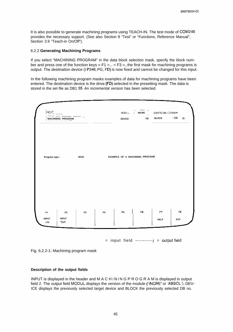
B8576654-02
It is also possible to generate machining programs using TEACH-IN. The test mode of COM246provides the necessary support. (See also Section 8 “Test” or “Functions, Reference Manual”,Section 3.9 “Teach-in On/Off”).
6.2.2 Generating Machining Programs
If you select “MACHINING PROGRAM” in the data block selection mask, specify the block num-ber and press one of the function keys < F1 >... < F3 >, the first mask for machining programs isoutput. The destination device (I P246, PG, FD) is now fixed and cannot be changed for this input.
In the following machining program masks examples of data for machining programs have beenentered. The destination device is the drive (FD) selected in the presetting mask. The data isstored in the set file as DB1 55. An incremental version has been selected.
EXAMPLE OF A MACHINING PFICGRAM
, ..– ——— —---~INpUT ~
~.. —— .,
. — -- ........, MODUL : INCRE j SIMATIC S5 / COM246,. ———. ----- ———— —------ .-; MACHINING PROGRAM DEVICE ~ FD BLOCK : DB @;. . . . . . . . . ---
Program type : MAIN
F1 F2 F3 F4 FFJ I W !=7 F8
INPUT INPUT HELP EXIT
= input f ie ld ~----- - - - - j = output field
Fig. 6,2.2-1: Machining program mask
Description of the output fields
INPUT is displayed in the header and M A C H I N I N G P R O G R A M is displayed in outputfield 2. The output field MODUL displays the version of the module (“INCRE” or “ABSOL”), DEV-ICE displays the previously selected target device and BLOCK the previously selected DB no.
45

0 8 5 7 6 6 5 4 - 0 2
Description of the input fields
In the first input field “program type” you can select between a main program (“9!.”) and a subrou-tine (“L”). The permitted entries are MAIN and SUB,
In the next input field, you can enter a comment, e.g. to provide information about the machiningprogram.
Significance of the function keys
< F1 >: With this function key you branch to input of machining programs according to DIN.< F2 > : With this function key you branch to input of machining programs in the TEXT [mode,< F7 >: With the help key you can select the type of program (MAIN or SUB).< F8 > : If you press the exit key, you will be prompted to confirm abandoning the machining
program, if you answer with YES you return to the basic mask (function selection) andif you answer NO you continue with machining program input.
6.2.3 Entering Machining Programs according to DIN
In the DIN representation, only one statement of a traversing program can be written per lineEach statement must begin with the statement type and statement number.
The IP246 processes all statements as “normal statements Normal statements are identified by“N” The statement identifiers “/N” for “suppressible statements” and “:N’ for ‘main statementare permitted, however, they have no significance.
The statement number comprises a maximum three digit number. The range of values is 0,,,999.Apart from the N function (statement type and statement number) the following functions are per-mitted:
L function (subroutine call)G function (preparatory positioning condition)X function (target function)F function (speed, time loop repetitions)M function (auxiliary function)
46
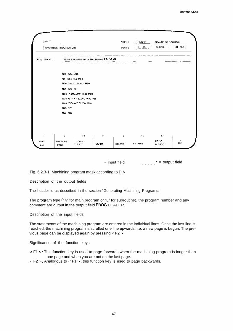
08576654-02
;INPUT MOOUL : ~;i(+ii” \, SIMATIC S5 / COM246L —--- - - - - -
; MACHINING PROGRAM OIN 1 DEVICE : ! FD ; BLOCK : DB (j55~j) _ — ---—..-..
. . . . . . . . . . . . . . . . . . .—. ... .——— —------ ----- . . . . . . ..---- —- —----. -— ————------ ————— —---(
Prog. header : f %155 EXAMPLE OF A MACHINING PRCGRAM,. —--- . . . . . . . . . . . . . . . . . . . . . . . . . . — . . . . . . . . . ... —. ——----- —- ——----- ——--—----. -..—-——.
NIO G74 MIO
N11 G04 FYJ Ml 1
N2u GOO Xl 10.WJ M2t)
N25 G24 F7
N 3 0 X.ZOO.OCO F45CKJ MWJ
N35 GIO X - 50.@20 F4CXY M3s
N40 X150,0CXJ F2Qc0 M40
N45 G20
NW M02
F1 F2 ; F3 ! F4 F5 F6 F7
NEXT PREVIOUS DIN -->~ ,NSERT
j PRINT 1 ‘8
PAGE T E X T DELETE s T O R E ~ M,PROGExIT
I 4
= input field ( = output field. . . . . . . . . . .
Fig. 6.2.3-1: Machining program mask according to DIN
Description of the output fields
The header is as described in the section “Generating Machining Programs.
The program type (“7.” for main program or “L” for subroutine), the program number and anycomment are output in the output field PROG HEADER.
Description of the input fields
The statements of the machining program are entered in the individual lines. Once the last line isreached, the machining program is scrolled one line upwards, i.e. a new page is begun. The pre-vious page can be displayed again by pressing < F2 >.
Significance of the function keys
< F1 >: This function key is used to page forwards when the machining program is longer thanone page and when you are not on the last page.
< F2 >: Analogous to < F1 >, this function key is used to page backwards.
47
B8576654-02
< F3 > :< F4 > :< F5 > :< F6 > :
< F7 > :
< F8 > :
With this key, you can switch to text representation.Function key < F4 > inserts a line in front of the current cursor position.Function key < F5 > deletes the line marked by the cursor.If the machining program is syntactically correct, this key stores the program on thepreviously selected device under the specified DB number. If the program alreadyexists on this device and with this DB number, you will be asked whether or not tooverwrite the data block.The machining program can be printed out by pressing this key. The masks are thesame as those for printing machine data (cf. Section 6.1.3 “Print Machine Data”). Whenmachining programs are being printed out, “MACHINING PROGRAM DIN” is displayedin the third output field of the header.With the exit key, the input function can be exited without saving the data.
6.2.4 Entering Machining Programs in the Text Mode
In the text mode, only one statement is displayed in a screen mask, The type of statement andthe G function can be selected using the help key < F7 >. With the other functions, the appro-priate numerical values must be entered.
~ INPUT. . --- . . ----- .-.., .MODUL : INCRE SIMATIC S5 / COM246. . . . . . . . .
; MACHINING PROGRAM TEXl DEVICE : ~ FD BLOCK : D9 : 155 ;.- . . . . . .
.—
,.. —------ . . . . . . . . . .~ mm Tooloffset: ; off j Offset : ! undef D i m e n s i o n s : a b s o l u t e,. ———----—.—, - . . . . . . . . . . .
Prog. header ! %155 EXAMPLE OF A MACHINING PROGRAM- - - - - - - - - - - - - - - - - - - - - - - - - - - - - - - - - - - - - - - - - - - - - - - - - - - - - - - - - - - - - - - - - - - - - - - - - - - - - - - - -
Stat. number 35 Stat. type : normal
Function 1 [L] : ;------------ ”---
Fun~tiOn 2 [G] ,Flying change
F~n~tio” 3 [X] : Target : .33 OaJ
Function 4 [F] : ~ Feed rate1 .
,------------!mmlmin4 0 0 ,----------- j.——— — - . - - - - - - - - . . . . .1
,- ——— — ---------- ,Fu”ctiot- 5 [M] : ] 3!3J
~FI F2
I
NEXT PREVIOUS
,- –---. ....,= input f ie ld I - - - - - - - - - - I = output field
Fig. 6.2.4-1: Machining program mask in the text mode
48
58576654-02
Description of the output fields
The header is as described in section “Generating Machining Programs”
Meas, system:The measuring system in which the displayed statement is to be interpreted can beseen in the first output field after the header. The default unit is mm. Alternatively, “O. 1in” will be displayed (G70 or G71).
Tool offset:The current tool length offset is displayed here. Possible displays are “off” (G40), “nega-tive” (G44) and “positive” (G43). “Off” is the default. Only the last selected G function(G40, G43 or G44) is displayed, not the resulting tool length offset, A change of sigrlfor example, G44 with -10 mm is not taken into account.
Offset:The last selected offset is displayed. Possible displays are “undef” (G53), “1 on (G54),“2 on” (G55), “3 on” (G56) and “4 on” (G57). “Undef” is the default.
Dimensions:The numerical values of the target functions (X functions) can be specified in “absolute”(G90) form or in “incremental” (G91) form, “Absolute” is the default,
Description of the input fields
Stat. number:The statement number is entered here as a numerical value, The statement nurmbercan be up to three digits long. It is not necessary to enter statements in ascendingorder. The individual statements are processed in the order in which they are enteredregardless of the statement number.
Stat. type:Using the help key, you can select one of the three possible statement types “main”(’:N’), “normal” (’N’) and “(suppressible” (’/N’),
L function:Entry of the subroutine number to be called by the current program. After entering asubroutine number, the text “subroutine no.” is displayed before the input field,
G function:Using the help key, you can display the possible G functions, Entry of other values is re-jected as an error.
X function:Here, the target is entered. The maximum range is +/- 40000,000. The value is either in-terpreted as a distance (with G91 ) or as an absolute coordinate (with G90).
F function:Depending on the previous functions, either the feed rate (following an X function), adwell time (following G04) or the number of repetitions (following G24) is entered. Theappropriate text (“feed rate”, “loop runthrough” or “dwell time”) is displayed before thisinput field and the appropriate dimension after the input field,
49

B8576654-02
M function:The M function is output at the beginning of the statement. The M function MOO means“programmed halt”, the M function M02 means program end, After M02, no further sta-tements can be appended. After entering M02, the text “program end” is displayedbefore this input field and the text “program halt” is displayed after entering MOO.
Significance of the function keys
< FI > :
< F2 > :< F3 > :< F4 > :
< F5 > :< F6 > :
< F7 > :
< F8 > :
With this function key you can display the next statement if the machining program islonger than one statement and the last statement is not currently displayed.Analogous to < FI >, you can page back one statement,This key switches over to text representation.The function key < F4 > inserts a new statement before the statement currentlydisplayed.The function key < F5 > deletes the displayed statement.If the machining program is syntactically correct, the program is stored on thepreviously selected device under the specified DB number with this key, If the programalready exists on this device under this DB number, you will be asked whether or not tooverwrite the data block.Using the help key you can select the alternatives for the fields “stat. type” and “Gfunction”.If you press the exit key you exit the input function without saving the data.
50

B8576654-02
7 output
By pressing < F2 > (OUTPUT) in the basic mask (“function selection(’) you branch to the“OUTPUT” function. Here, machine data or machining programs can be output from the module,the PG or from a floppy/hard disk drive. It is then possible to change the data and write it back tothe source, The function keys < F1 >... < F8 > have the same assignment as in input, The masksare also identical with the exception of the header. Here, OUTPUT is displayed instead of INPUT.
The first mask is the block selection mask, Here, you must select the data block you wish todisplay. You can select machine data or machining programs using the function key < F7 >(HELP). After specifying
the block number,the axis number (only for machine data output) andthe source device (with < F1 >... < F3 > ) from which the data block is to be read,
the first machine data/machining program mask will be displayed.
7.1 Output Machine Data
Description of the output fields
OUTPUT and M A C H I N E D A T A are displayed in the header. The version of the module(“INCRE” or “ABSOL”) is displayed in the output field MODUL, the previously selected sourcedevice in DEVICE and the DB no. in BLOCK,
Description of the input fields
The input fields for machine data are completed with the stored values. You can modify the dataand write them back to the source device with the function key < F6 > (TRANSFER). Otherwisethe mask is the same as for the input of machine data.
7.2 Output Machining Program
Description of the output fields
OUTPIJT and M A C H I N I N G P R O G R A M are displayed in the header The W3SIO!1 Of the
module (’(INCRE” or “ABSOL”) is displayed in the output field MODUL, the previously selectedsource device in DEVICE and the DB no. in BLOCK.
51

B8576654-02
Description of the input fields
The machining program of the selected data block is displayed. It is possible to change irldivl -dual statements and to write them back to the source device with the function key < F6 >(STORE). Otherwise, the mask is the same as for the input of machining programs.
52
B8576654-02
8 Test
In this branch of the program you can test the IP246 module and the drive in all operatingmodes. Machining programs can be started manually and already existing machining progra[mscan be tested, Actual values are displayed at the PG online. The test mode also allows machiningprograms to be generated in TEACH-IN.
Note:
Owing to a hardware feature of the programmers, the keys have a repeat function. Thismeans that if you press a key for a longer time, its key code will be written to the keybuffer until it is processed. This means that commands will be processed until the buffer isempty. A STOP command may, therefore, not be executed immediately This is not anerror, the stop command will be executed. Commands entered accidentally after the stopcommand will, however, also be executed.
8.1 Starting the Test Mode
By pressing < F3 > (TEST) in the basic mask (function selection) you branch to the “test’function.
Conditions:The mode is online. You can change the mode in the presetting mask using thefunction key < F2> (ONLINE-OFFLINE).The link from the PG to the IP246 is established andthe IP246 is operational (green LED lit).
In this section, each mask has values entered in the input and output fields. For the example, wehave used an absolute version of the IP246 and the dimensional unit is in mm.
53
B8576654-02
MODUL :@5$~;;;; SIMATIC S5 I COM246
ITEST I DEVICE : ; 1P 246 i BLOCK : DB
J
Actual value
~ Following errorJ
Distance to go
Aux. function
.— -—-—-- .- .. ---.,~ Home point
Teach-in mode
Mode
Program
Distance
F1~ ‘2 ~ ‘3
AXIS Pxs
~--Current .w.is : ,1
: set ;... ..- —--———~- —- —— —-—..off,— –...–——.-—,
4
CLC : ~ on
Status fimshed I,.
FOLLOWING ERROR
Inlm]
(1 ‘% ..2@3 %)
F4 i F5 F6 ; F7 ; F8
I I EXITI I
= input field I j = output field
The first mask in “test” is the test axis selection mask.
Fig. 8.1 -1: Test axis selection
Description of the output fields
T E S T is entered in the header. The version of the module (“INCRE” or “’ABSOL”) is displayed inthe output field MODUL and “IP246” in DEVICE.
Significance of the function keys
< F1 >: Test axis 1. After pressing this key, the program branches to the mode mask,< F3 >: Test axis 2. After pressing this key, the program branches to the mode mask.< F8 > : The EXIT key returns you to the basic mask (“function selection”),
B8576654-02
8.2 Modes
If you select the axis with < F1 > (axis 1 ) or < F3 > (axis 2) in the test axis selection mask, youbranch to the mode mask, to the actual value display mode.
MOOUL :; ABSOL - , SIMATIC S5 / COM246,––-––– . . . . . . . . .
‘ INCREMENTAL ABSOLUTE START, - - - -—-. .7
DEVICE :’ 1P 246 ] BLCCK : OB.- ——.—. .-. ... ... .—.. —-.--—--- .—. —.- ---- —..- —
,Current axis : ~-l-– j
Actual value
.—— —-...-. —— –-... ..=Followna error
Mode
Program
Oistance
Override
F1
1
F2
5 . 6 0 2 [ m m ], - — - . . . . . .
12U (1 % ,..200 %)
F4 I F51
F6 ~ F7 I F8F3
‘ ---------- = output field= input field I
Fig. 8.2-1: Mode mask
Description of the output fields
The version of the module (“INCRE” or “ABSOL”) is displayed in the output field MODUL and in“IP246” in DEVICE. The remaining text in the header depends on previous entries. Either simply“TEST” is entered or “TEST” and the current operating mode of the axis and the last command tobe executed are displayed.
Note: If you return to the basic mask (“function selection”) by pressing function key< F8 > (EXIT) in the test axis selection mask, COM246 starts operating mode 17(“clear error”). This is then displayed in the mode mask in output field 3 in theheader.
Actual value:The current position coordinate (actual position value) of the selected axis is displayed.The value is displayed in the appropriate dimension.
55
B8576654-02
The text “following error:” does not appear in the operating modes “JOG OPEN LOOP” (mode 3)and “FOLLOWING ERROR” (mode 4). In these modes, the text “speed :“ is displayed at this point.
Following error:This field displays the difference beween the actual position value and the setpoint (notin modes “JOG OPEN LOOP” and “FOLLOWING ERROR”)
Speed:The current speed of the axis is displayed (in modes “JOG OPEN LOOP” and “FOLLO-WING ERROR”).
Distance to go:This displays the difference between the actual position value and the target coordina-te. This only applies to modes “AUTOMATIC” and “AUTOMATIC SINGLE STATEMENT”“INCREMENTAL ABSOLUTE” and “INCREMENTAL RELATIVE.
Aux. function:In the modes ‘(AUTOMATIC” and ‘(AUTOMATIC SINGLE STATEMENT” the programmedM function is displayed as a numerical value, The auxiliary function (M function) M02 isthe default.
The text “home point:’” is only displayed with the absolute version (“ABSOL”), With the incremen-tal version (’(I NCRE”), the text “reference point:” is displayed here.
Home/reference point:With the incremental version, this field shows whether the reference point is set” or“reset”, with the absolute version it shows whether the home point is “set” or reset(not set),
CLC (closed-loop controller):This field indicates whether you are using closed-loop or open-loop control. The possi-ble displays are “on” or “off”.
Teach-in mode:This displays whether the selected axis is in teach-in (“on”) or not (“off”)
Axis status:Here, the status of the axis is displayed. Possible displays are “finished” and ‘running”.
If there are no correct machine data for the axis on the module, then no actual value, no follo-wing error (speed) and no distance to go will be displayed. The statuses reference/home point,CLC, teach-in mode and axis status remain unchanged. Without machine data, only modes 4 (fol-lowing error) and 17 (clear error) can be executed apart from input and output of data
Note:
With the incremental version of the IP246, a correct actual value display is onlyguaranteed when the module has not been switched off and on again after startingCOM246 (online mode). After starting up the IP246 again, you must switch to the basicmask by pressing < F1 > (BEGIN) in the presetting mask.
56
B 8 5 7 6 6 5 4 - 0 2
Description of the input fields for changing modes
The inversely displayed input fields are only completed after pressing function key < F1 > (OPMODE). If you press < F1 >, the mask changes to the change mode function.
Note:
The displayed values, actual value (actual position value), following error (speed), distanceto go, auxiliary function and the displayed axis attributes ( = > “Fundamentals ofPositioning, Reference Manual”, Section 6 “Axis Attributes”), are then no longer updated.
The function key < F1 > changes to “ACTUAL VALUES”, the function key < F7 > changes to“HELP”. By pressing < F1 > (ACTUAL VALUES) you return to the actual value display mode.
Mode:Here, the required mode and selected axis are entered. The mode can be selectedfrom the mode table with the HELP key < F7 >, After entering the mode number (right-justified), the corresponding text is displayed to the right of the mode number. Modes1.,.19 are permitted. If a different number is specified, you branch automatically to themode table. Depending on the selected mode, the function keys < F2 >... < F6 > havedifferent functions. In mode 5 (REFERENCE/HOME POINT APPROACH), a furtherinput field is displayed, Providing an incremental version has been selected (configura-tion mask), you can select between “set” and “run” by pressing the help key c F7 ~>.
Program:This input field can only be written to in modes 8 (AUTOMATIC), 9 (AUTOMATICSINGLE STATEMENT) and 10 (TEACH-IN ON), In these cases, the machining programnumber must be entered.
Distance:The distance input field can only be written to in modes 6 (INCREMENTAL ABSOLU-TE), 7 (INCREMENTAL RELATIVE), 12 (ZERO OFFET ABSOLUTE), 13 (ZERO OFFSETREIATIVE) and 15 (TOOL OFFSET). In each case the distance or coordinate must beentered in the selected dimension.
Override:This input field can only be written to in modes 1 (JOG SPEED 1), 2 (JOG SPEED 2), 3(JOG OPEN LOOP), 6 (INCREMENTAL ABSOLUTE) and 7 (INCREMENTAL RELATl -VE). You can change the speed of the axis stored in the machine data by a percentage(1%...200%).
Significance of the function keys
< F1 >: With < F1 >, you can switch between the actual value display mode and the modechange function. In the actual value display mode the va!ues actual value, followingerror (speed), distance to go, aux. function and the displayed axis attributes of theselected axis are displayed and continuously updated. If you select the mode changefunction the mode and corresponding parameters can be changed.
< F2 >: “START” is only permitted in modes 4...6, 8...12 and 14...19.c F3 >: “STOP” is only permitted in modes 1...4 and 6...9.< F4 >: The command “FWD” is permitted in modes 1...3, 7, 13 and 15. If a rotary axis is
selected as the axis type, the “FWD” command is also permitted in mode 6.< F5 >: The command “BACK” is permitted in modes 1.,3, 7, 13 and 15. If a rotary axis is
selected as the axis type, the “BACK” command is also permitted in mode 6.
57

B8576654-02
< F6 >: The function of the “TRANSFER” key depends on the mode.In operating modes 1...3, 6 and 7 the speed of the current operating mode (axisstatus “running”) can be changed. The number of the current operating mode mustbe entered in the mode change function. The speed is modified according to theoverride when the “TRANSFER” key is pressed. The resulting speed must remainwithin the permitted limits following the override change.In the “AUTOMATIC SINGLE STATEMENT” mode, this key executes the next state-ment of an automatic program.In the “AUTOMATIC” mode, the “TRANSFER” key is used to acknowledge a pro-grammed halt (MOO).If the teach-in mode is active and the axis status is “finished”, the “TRANSFER” keyis used to save a statement.
< F7 >: Providing the cursor is located in the input field “mode”, the HELP key < F7 > can beused to branch to the mode table. From this table you can select a mode and return tothe mode mask with < F6 > (TRANSFER), In mode 5 (REFERENCE POINT), the HELPkey can be used to switch between “SET” and “RUN” (only with the incrementalversion).
< F8 >: The EXIT key returns you to the test axis selection mask, The header remainsunchanged.
8.3 Mode Table
By pressing the HELP key in the mode mask (mode change function), you can branch to themode table mask. This contains all the possible modes and mode numbers.
58

B8576654-02
r ~.–.–-––-.. --- . .( 1
I TEST, –___. .––––-- -–– ’ MODUL :1 ABSOL ~L— .......7SIMATIC S5 / COM246
... .————.— —-- ——————-- — — --------- —-! INCREMENTAL ABSOLUTE START
!1
L — — - — — . . _ . . . . . . . . . _ _ . . . . — . — — - - - - . . . . . . . . . D E V I C E : [~P;~~---i BLOCK : D13,--— —.. . . ,
F1
I
Operating modes for testing
1
2
3
4
5
6
7
8
9
JCG speed 1
JOG S+ 2
JOG open hop
Follcwing error
Reference pant approach
Incremental absolute
incremental relative
Automatic
Autom. single statement
10 Teach-in on
—.11 Teach.in off
12 Zero offset absolute
13 Zero offset relative
14 Clear zero offsd
15 Tool offset
16 Twl offset off
17 Clear error
18 Drifl compensation
19 Drift comwnsation off
Enter number of operating mode: 5
F2I
F3 I F4 ~ F5 ! F6 ‘ F7
IF8
– input field I --------— j = output field
Fig. 8,3-1: Mode table
Description of the output fields
The header remains unchanged.
Description of the input field
The mask has only one input field in which the number of the required mode is entered. All othervalues apart from those listed lead to the error message “FFF input prohibited”.
Significance of the function keys
< F6 >: Using the “TRANSFER” key the operating mode number is entered in the “mode” fieldof the mode mask. The corresponding text is displayed at the same time.
< F8>: The exit key returns you to the mode mask (mode change function). “FOLLOWINGERROR” is then entered as the operating mode.
59
B8576654-02
9 Transfer
By pressing < F4> (TRANSFER) in the basic mask you branch to the transfer mask.
In this branch of the program you can transfer machine data or machining programs from onedevice to another.
I 1I TRANSFER,___-—_ —__ - — __ --_____, –7~ MACHINE DATA:—-——---—-—--——-—--——- -- —-. . . . . . ;
M O O U L :f;i~ii----; SIMATIC S5 / COM246. . . . . . . .~.-......: . . . . . .
DEVICE :i FD ~ BLCCK : DEI ] 123 I.—-— —----- - ._. J
Device
Block no.
A.is
Dwe
Filename
Plant design, :
Generated by :
Generated on :
FI I F2I
Data block :
Source
FO
123
1
A
EXAMPLE
; SMITH I. . . . . . . . . . .,––-–––-–j 12.06,89 I
F3 F4
TRANSFER
,——. —.. ------ . –— . .~ MACHINE DATA - J
Target
1P 246 (* = all VDATI
123
1
1I
HELP EXIT
= input f ie ld ~__------j = ou tpu t field
Fig. 9-1: Transfer mask
Description of the output fields
The version of the module (“INCRE” or “ABSOL’1) is displayed in the MODUL field. Following thestart of the transfer, TRANSFER and either M A C H I N I N G P R O G R A M or M A C H I N E DA T A are entered in the header. The output fields BLOCK and DEVICE are completed with the ap-propriate values. The DB number of the data record to be transferred is displayed in BLOCK andthe source device is entered in DEVICE.
61
B8576654-02
Description of the input fields
Data block:
DB no.
Axis:
Drive:
With < F7 > (HELP) you can select between machine data and machining programs.Device: with < F7 > (HELP) you can select the source or destination device, The possi-ble entries are module (I P246), the programmer (PG) or the data drive (FD)
As the source, the number of the block to be transferred must be specified, The samenumber will be entered as the target. This can, however, be changed, The range ofvalues is from 0,,,55. If a “*” is entered for the DB no. of the source, all DBs (eithermachine data or machining programs) on the selected source device will be transfer-red to the destination device, The DB number of the destination device is then mea-ningless,
Note:The PG can only store one machine data record and one machining progranl
When transferring machine data, the axis number in the machine data record to betransferred must be entered under source, If there is no machine data record with thisaxis number on the selected device, the error message ‘data block missing” is display-ed. When transferring the machine data, it is possible to change the axis number of thetarget DB,
If the selected source device is a floppy or hard disk the name of the drive is also requi-red. You can use the HELP key < F7 > to make the entry.
File name:If the source is a drive (floppy or hard disk) the file name must be selected using thehelp key, If there is no file on the selected drive with the extension .246 (incrementalversion) or .A46 (absolute version) no DB can be transferred. In this case the errormessage “data block missing” is displayed. If the target device is a drive, the file nameselected in the presetting mask will be used and the corresponding data for plant desi-gnation, generated on and generated by will be displayed in the appropriate fields,
You can only transfer to the drive selected in the presetting mask,
Significance of the function keys
< F4 >: This function key starts the transfer,< F7 >: The help key can be used to make selections in the “block number”, source device and
destination device fields. Remember that no blocks can be transferred if the sourceand destination device are identical, Otherwise, possible source drives and the filescontained can be selected.
< F8 >: Pressing this function key abandons the “TRANSFER” function and you return to thebasic mask (“function selection”).
62

08576654-02
10 Delete
Pressing < F5 > (DELETE) in the basic mask (“function selection”) branches to the delete mask,
In this program branch you can delete machine data or machining programs stored on a device(I P246, FD, PG).
Data block : MACHINE DATA Axis 1
Source dev,ce IP246 3LOCK NC 2t2 123 ;. all D%)
I , ! IF1 I F2 ! F3 ; F4 F5 ~ F6 F7 Fe
II I
I I ~ DELETE HELP EXI1
= input field I j = output field
Fig. 10-1: Delete mask
Description of the output fields
The version of the module (“INCRE” or “ABSOL”) is displayed in the MODUL field. After startingthe delete function, DELETE and either M A C H I N I N G P R O G R A M or M A C H I N E D A TA are displayed in the header. The output fields BLOCK and DEVICE are then completed with theappropriate entries. The DB number of the data record to be deleted is displayed in BLOCK andthe device containing the data record to be deleted is displayed in DEVICE,
63
B8576654-02
Description of the input fields
Data block:< F7 > (HELP) can be used to select between machine data and machining programs.
Axis:If machine data are to be deleted, the axis number of the machine data record to bedeleted must be entered here. This number is stored in the machine data record
Source device:With < F7 > (HELP) you can select the device on which the data block is to bedeleted. Possible selections are module (I P246), the programmer (PG) or the datadrive (FD).
Block no:The number of the block to be deleted is entered here, The range of values is 0...255, Ifyou enter “*” all DBs (machine data records or machining programs) on the selecteddevice will be deleted.
Significance of the function keys
< F5 >: This function key starts the delete function.c F7 > : Using the help key you can select alternatives in the “data block” and “source device”
fields.< F8 > : With this function key you abandon the delete function and return to the basic menu.
64
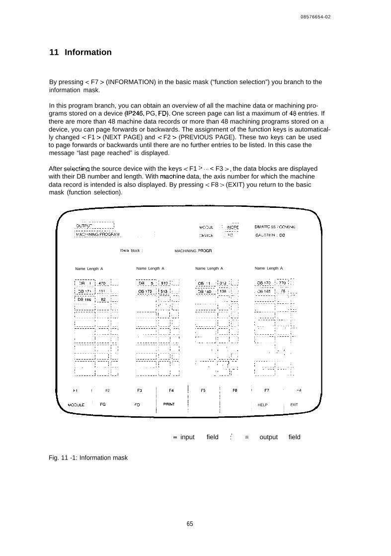
08576654-02
11 Information
By pressing < F7 > (INFORMATION) in the basic mask (“function selection”) you branch to theinformation mask.
In this program branch, you can obtain an overview of all the machine data or machining pro-grams stored on a device (IP246, PG, FD), One screen page can list a maximum of 48 entries. Ifthere are more than 48 machine data records or more than 48 machining programs stored on adevice, you can page forwards or backwards. The assignment of the function keys is automatical-ly changed < F1 > (NEXT PAGE) and < F2 > (PREVIOUS PAGE). These two keys can be usedto page forwards or backwards until there are no further entries to be listed. In this case themessage “last page reached” is displayed.
After selectirm the source device with the keys < F1 >.,, < F3 >, the data blocks are displayedwith their DB number and length. With mach;ne data, the axis number for which the machinedata record is intended is also displayed. By pressing < F8 > (EXIT) you return to the basicmask (function selection).
Data block : MACHINING PROGR
Name Length A
,FI ! F2
Name Length A Name Length A
. . . .; , ‘,, !--—J l--!
‘-------: ~---: ~-- ;
-; l.. ..’ L.-
,—-——I , ;
J !. . .
; r–l
-. 1’ ---- ., L. !; ------- ; ;.. -., , . .> !- ..’ :. .-- . . . .
,,.J I .- ..-; ‘L-;
SIMATIC S5 I COM246
BAUSTEIN : DB
Name Length A
:,—, ,.. : ;
IHELP I EXIT
I
.. —--------. input field I ! = output field
Fig. 11 -1: Information mask
65
08576654-02
Description of the output fields
After starting the information function, INFORMATION and either M A C H I N I N G P R O G R AM or M A C H I N E D A T A is entered in the header, The source of the data is displayed in theDEVICE output field. The BLOCK output field remains unchanged.
Description of the input fields
Data block:Using < F7> (HELP), you can select between information about machine data or infor-mation about machining programs.
Significance of the function keys
< F1 > ,.< F3 > :With these function keys you select the devices (I P246, FD or PG) from which the datablocks are to be read. If there are more than 48 entries < F1 > and < F2 > are assi-gned the paging function.
< F4 >: This starts the printout of the data blocks.< F7 >: The help key is used to select the type of data block (machine data or machining
programs).< F8 >: With the EXIT key you can exit the information function.
66

SIEMENS
SIMATIC S5IP246 Positioning Module Incremental
AbsoluteStandard Function Blocks FB164 and FB165
6ES5246-4UA31 / -4UA416ES5246-4UBI 1 / -4UB21
User’s Guide C79000-B8576-C655 -02
B8576655-02
Contents
1 General Notes . . . . . . . . . . . . . . . . . . . . . . . . . . . . . . . . . . . . . . . . . . . . . . . . . . . . . . . . . . . 51.1 Overview . . . . . . . . . . . . . . . . . . . . . ,, ,..., ., . . . . ........51.2 Notes . . . . . . . . . . . . . . . . . . . . . . . . . . . . . . . . . . . . . . . . . . . . . . . . . . . . . . . . . . .....61.2.1 Overview ofthe Handling Blocks ., ..,, ., ., ., ., ., ., ., ......61.2.21nstallingan interface in OB20,0B21 or OB22withthe S5 135U .....,,.,., . . . ........7l.3Using FB164/FB165 inthe S5115U . . . . . . . . . . ,,, . .,, ,, .,..., . . . . . ........71.3.1 interrupting the User Program by Processand Time lnterruptsinthe S5 115U . ........71.3.2 Start-up Characteristics ofthe S5115U . . . . . . . . . . . . . . . . . . . . . . . . . . . . . . 7l,4Using FB164/FB165 in the S5135U(CPU922 and CPU928) . . . . . . . . . . . . . . . . . . . . . . . 81.4,1 interrupting the User Program by Process andTime lnterruptsinthe S5 135U
(CPU922 and CPU928) . . . . . . . . . . . . . . . . . . . . . . . . . . . . . . .. ......81 . 4 . 2 S t a r t - u p C h a r a c t e r i s t i c s o f t h e S 5 135U (CPU922 and CPU928) .. .....8l.5Using FB164/FB165inthe S5 150U ,,, ,,, ,,, .,, .....,.,, .. ...91.5,1 Interrupting the User Program by Process and Time Interrupts in the S5 150U .. ...91.5.2 Start-up Characteristics of the S5 150U ., ., ... ..91 . 6 U s i n g FB164/FB165 inthe S 5 1 5 5 U ,, , . , . . , . . . , , . , , . . . . , , , , . . . . . . . . . 91,6.1 Interrupting the User Program by Process and Time Interrupts in the S5 155U .. ...91.6,2 Start-up Characteristics of the S5 155U ., ., ., ., ., ., ., ., 101.7 Using the Positioning Module in Multiprocessor Operation (applies to the
S5 135Uand S5 155U) . . . 10
2 The Standard Function Block FB164 ., . . . . . . . . . . . . . . . . . . . . . . . . . . . . . . . . . . . . . . 112.1 Functional Description ., ., ., ., ... ., ., ... ., 112.2 Calling Function Block FB164 ., ., ., 122,2.1 S5 135U, S5 150U, S5 155U ., 122.2.2 S5115U . . . . . . . . . . . . . . . . . . . . . . . . . . . . . . . . . . . . . . . . . ~~ŠŒ 122.30verview of the Parameters . . . ., ., ,., ., ., 132.4 Explanation ofthe Parameters . . . . . . . . . . . . ., ..., ., 142.5 Notes on using Actual Operands . .........,,.,,.,,., , 182.6 Relationship between the ParameterTBITand the current Checkback Signals . . . . 1 92,6,1 General . . . . . . . . . . . . . . . . . . . . . . . . . . . . . . . . . . . . . . . . . . 192,6,2 The ParameterTBlTwith the individual Modes . . . . . . . . . . . . . . . . . . . . . . . . 192.7 Data Area Requirements . . . . . . . . . . . . . . . . . . . . . . . . . ..,, . . . . . . . . . . . . . ...232.7.1 Indirect Assignment of Parameters toFB164 . . . . . . . . . . . . . . . . . . . . . . . . . . . . . . ....232.7.2 Structure oftheAxis Data Block ..,... . . . . . . . . . . . . . . . . . . . . . . . . . . . .242.8 Technical Data ofFB164 . . . . . . . . . . . . . . . . . . . . . . . . . . . . . . . . . . . . . . . . . . . . .......282 .9 Us ing Func t ion B lock FB164 . ................,.,.,...,.,,,,,, . . . . . . . . . . .......292.9,1 Special Feature ofthe Parameter STOP . . . . . . . . . . . . . . . . . . . . . 312,9,2 Special Features of the ParametersVORW and RACK, ,,, . . . . . . . . . . . . . . . . . . . . 312.9,3 BCD Output . . . . . . . . . . . . . . . . . . . . . . . . . . . . .,, ,, ..,.,..312.9,4 BCDOutputwiththe S5 115U . . . . . . . . . . . . . . . . . . . . . 323 Standard Function Block FB165 . . . . . . . . . . . . . . . . . . . . . . . . . . . . . . . . . . . . . , . . . . . .......333.1 Functional Description . . . . . . . . . . . . . . . . . . . . . . . . . .. ....333.2 Calling Function Block FB165 . . . . . . . . . . . . . . . . . . . . . . . . . . . . . . . . . . . . . . . . . . .343.30vewiew of the Parameters . . . . . . . . . . . . . . . . . . . . . . . . . . . . . . . . . . . . . . . . .. ....343.4 Explanation ofthe Parameters . . . . . . . . . . . . . . . . . . . . . . . . . . . . . . . . . . . . . . . 353.5 Notes on using Actual Operands . . . . . . . . . . . . . . . . . . . . . . . . . . . . . . . . . . . . . . .......383.60verview of the Permitted and Advisable Parameter Area forthe
Standard Function Block FB165 . . . . . . . . . . . . . . . . . . . . . . . . . . . .......393.7 Data Area Requirements . . . . . . . . . . . . . . . . ,. ..403.7.1 indirect Assignment of Parameters toFB165 . . . . . . . . . . . . . . . . . . . . . . . . . . . . ...403.7.2 Structure oftheAxis Data Blockforan Axis ..., ., ., .413.8 Structure of the Source or Data Blocks in the PC Memoryforthe Individual Modes .. .....42
2
B8576655-02
3.8.1 Structure of a Machine Data DB in the PC Memory ., . . . .. ...423.8.2 Structure of a Machining Program DB in the PC Memory . . . . . . . . . . . .. ...463.8.3 Structure of the SYSID of the IP246 in the PC Memory . . . . . . . . . . . . . .......483.8.3.1 Read SYSID (BA = 70) . . . . . . . . . . . . . . . . . . . . . . . . . . . . . . . .......483.8.3.2 SYSID Input (BA = 24) . . . . ., ... .. ..493.8.4 Structure of the Machine Data Directory ., . 493.8.5 Structure of the Machining Program Directory ., ., ., ., ., .503.8.6 Occupation of the Data Word when reading Actual Values ... .. ..533.8.7 Structure of the Machine Data Overview ., ., ., ... ... ., .. .543.9 Technical Data . . . . . . . . . . . . . . . . . . . . . . . . . . . 553.10 Notes on Starting Upthe Positioning Module lP246via the PClnterface .563.11 Using the Function Block . . . . . . . . . . ., ... ., ., ., 57
4 Examples . . . . . . . . . . . . . . . . . . . . . . . . . . . . . . . . . . . . . . . . . . . . . . . . . . . . . . . . . . . . . 594.1 General Notes on the Examples . . . . . . . . . . . . . . . . . . . . . . . . . . . . . . . . . . . . . . . . .. ..594,2 Hardware Requirements ., ., ... . . ... ., ., ... ., ... ..594.3 Assignments forthe Examples ., . . . . . . ... ., ., .604.3,1 Digital inputs: (valid forall Programmable Controllers) . . . . . . . . . . . . . . . . . . .. ..604.3.2 Digi ta l Outputs: (val id for S5-135U, S5-150U and S5-155U) ., ., ., ., ., ..614.3,3 Digital Outputs: (valid for S5-115U) . . . . . . . . . . . ., ., ., .. .....614.3.40 ccupation of the Data Area ..,,...,,.,,..,,.,,. . . . . . . . . . . . . . . . . . .. ...614.3.50 ccupation of the Flag Area . . . . . . . . . . . . . . . . . . . ..614.3.6 Block Assignments ., ., ... ., .624.4 Schematic Diagrams of the Organization Blocks (Program Framework) .. .....634,4.1 OB1 . . . . . . . . . . . . . . . . . . . . . . . . . . . . . . . . . . . . . . . . . . . . . . . . . .......634.4.2 Thelnterrupt OBs . . . . . . . . . . . . . . . . . . . . . . . . . . . . . . . . . . . . . . . . . . . . .......634.5 Example of Function Block FB164 . . . . . . . . . . . . . . . . . . . . . . . . . . . . . . . . . . . .. .644,5,1 The Function Block FB53 (Schematic Diagrams) ... ., ., 644,5,2 The Function Block FB54 (Schematic Diagrams) ., ... . . . . . . . . . . ... ..644.6 Example of Function Block FB165 . . . . . . . ., ., ... ., ... ... ., ... .644.6.1 Overview of the Relationship between the Mode and the Data Blocks in the
RAMofthe CPUandthe Positioning Module . . . . . . . . . . . . . . . . . . . . . . . .. ...664 . 6 . 1 . 1 W r i t i n g D a t a t o t h e l P 2 4 6 a n d D e l e t i n g D a t a onthelP246 . . .664.4.3 OB21 and OB22 with S5 115U
OB20 and OB22 with S5 135UOB20 with S5 150U and S5 155U . . . . . . . . . . . . . . . . . . . . . . . . . . . . . . . . . . . . ..66
4,4.4 OB21 with S5 135U, S5 150U and S5 155UOB22 S5-150U . . . . . . . . . . . . . . . . . . . . . . . . . . . . . . . . . . . . . . . . . . . . . . . . . . . . . . . . 66
4.6.1 .2 Reading Data from thelP246 . . . . . . . . . . . . . . . . . . . . . . . . . . . . . . . . . . . . . . . . . . . . ,., 674.6.2 The Funct ion Block FB51 (Schematic Diagrams) . . . . . ., ... ., . . .......694.6,3 The Function Block FB52 (Schematic Diagrams) . . . . . ., . . . . . .......69
3

B8576655-02
1 General Notes
1.1 Overview
This part describes the two standard function blocks
FB164 (PER:POS) “operating and monitoring the positioning module” andFB165 (PER :PDAT) “positioning module parameter assignment”
FB164 is used to operate and monitor the IP246 positioning module. With FB164 you can startthe IP246 operating modes 1...19 from the user program. FB164 also supplies constantlyupdated information about the current status of an axis (errors, M functions, ... ). As soon as oneof the monitoring modes is started, the selected value is read and output cyclically by FBI 64.
FB165 is used to assign parameters to the IP246. It is responsible for the data exchange betweenyour user program and the IP246. By calling FB165, you can execute the following functions viathe PC interface:
— read machine data and machining programs from the IP246, delete them and transfer them tothe IP246,read the system identification from the IP246 and transfer it to the IP246,request an overview of the machine data or machining programs stored on the IP246 andread actual values (actual position value, following error or speed, distance to go).
The function blocks FB164 and FB165 are used in the following programmable controllers
S5 115U (CPU 941 to CPU 944)S5 135U (CPU 922 and CPU 928)S5 150US5 155U
in conjunction with the following IP246 positioning modules
6ES5 246-4UA31 (incremental version for ventilated operation)6Es5 248-4UA41 (incremental version for non-ventilated operation)6ES5 246-4UB11 (absolute version for ventilated operation)6ES5 246-4UB21 (absolute version for non-ventilated operation)
This User’s Guide assumes that you are familiar with the IP246 and the programmable controller.
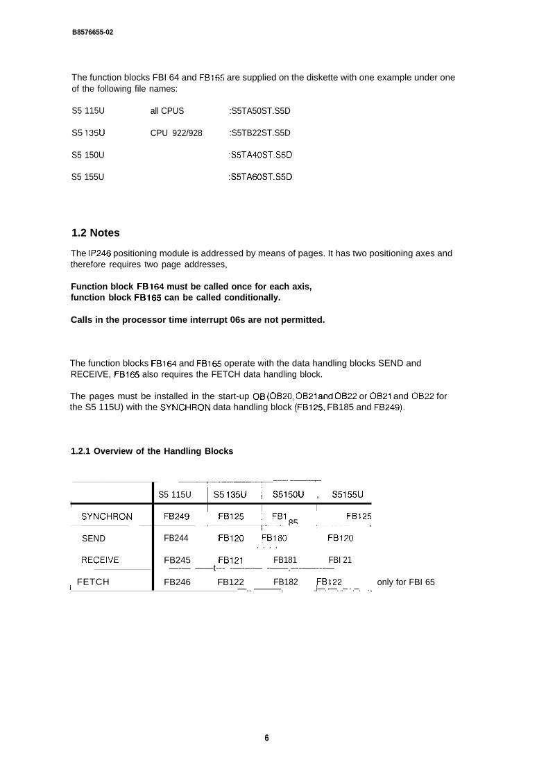
B8576655-02
The function blocks FBI 64 and FB165 are supplied on the diskette with one example under oneof the following file names:
S5 115U all CPUS :S5TA50ST.S5D
S5 135U CPU 922/928 :S5TB22ST.S5D
S5 150U :S5TA40ST.S5D
S5 155U :S5TA60ST.S5D
1.2 Notes
The IP246 positioning module is addressed by means of pages. It has two positioning axes andtherefore requires two page addresses,
Function block FB164 must be called once for each axis,function block FB165 can be called conditionally.
Calls in the processor time interrupt 06s are not permitted.
The function blocks FB164 and FB165 operate with the data handling blocks SEND andRECEIVE, FB165 also requires the FETCH data handling block.
The pages must be installed in the start-up OB (OB20, OB21 and 0B22 or 0B21 and OBZ2 forthe S5 115U) with the SYNCHRON data handling block (FB125, FB185 and FB249).
1.2.1 Overview of the Handling Blocks
‘---- ~“-——-
1 ~
—..—.—.——— —–———.——.– —..
S5 115U S5 135U S5150U , S5155U iI~ SYNCHRON
I IFB249 ~ FB125 ‘ FB125
,——— ..y..——.—.—— .t--.B-l-l 85..–...--+--------- ,
SEND FB244 ~ FB120 FB18G ~ FB120. . . .
RECEiVE FB245 FB121 FB181 FBI 21—-— ——t--- -—-–-— -——.–--—–---— ––——–
i FETCH FB246 FB122 FB182 FB122 only for FBI 65—.. ———. ..l—–. -—–. ..— - .—. . .
6
B 8 5 7 6 6 5 5 - 0 2
1.2.2 Installing an Interface in OB20, OB21 or OB22 with the S5 135U
: JU FB125NAME : SYNCHRONSSNR : KY0,2 Interface 2BLGR : KYo,o Block size (always 0,0)PAFE FYI SYNCHRON parameter assignment error
The SYNCHRON call must be programmed for each interface to be addressed in the cyclicprogram section (cf. Section 4 “Examples”).
1.3 Using FB164/FB165 in the S5 115U
1.3.1 Interrupting the User Program by Process and Time Interrupts in the S5 115U
The user program is always interrupted at command boundaries
If interrupt OBS are programmed in the user program in which the scratchpad flag area (flag byteFY200 to FY255) is used, you must ensure that this flag area is saved and loaded agair beforeexiting the interrupt OBS.
It is not permitted to call data handling blocks in the interrupt branches
1.3.2 Start-up Characteristics of the S5 115U
Cyclic program execution following “cold restart” (OB21 ) and following an “automatic warmrestart” (OB22) begins at the start of OB1.
The function blocks FB164 and FB165 are normally not called in the start-up OBS (OB21 andOB22).
In the start-up OBS (OB21 and OB22) the binary identifiers for all axes used must be deleted(overwritten with the value KHOOOO).
The binary identifiers required by FB164 are stored in the axis data block in data words DWn + 14. (n is the same as the parameter DWNR in FB164.)
The binary identifiers required by FB165 are in the parameter assignment data blocks (parame-ter: DBNR) in data words DW n +6. (n is the same as the parameter DWNR in FB165.)
68576655-02
1.4 Using FB164/FB165 in the S5 135U (CPU922 and CPU928)
1.4.1 Interrupting the User Program by Process and Time Interrupts in the S5(CPU922 and CPU928)
135U
The user program is interrupted at the block boundaries or at the command boundaries if datablock DXO is assigned suitable parameters.
If interrupt OBS are programmed in the user program in which the scratchpad flag area (flagbytes FY200 to FY255) is used, you must ensure that this flag area is saved and loaded againbefore exiting the interrupt OBS. The same applies to the operating system data RS60 to RS63.
If the program can be interrupted at the command boundaries, the handling blocks must not becalled in the interrupt branch. If this is, however, required, you must ensure that function blockFBI 64 or function block FB165 cannot be interrupted during the cyclic program.
1.4.2 Start-up Characteristics of the S5 135U (CPU922 and CPU928)
Cyclic program execution following a “cold restarl’ (OB20) begins at the start of OB1
With the “warm restarts”, OB21 (manual warm restart) or OB22 (automatic warm restart) theprogram is continued at the point of interruption after the start-up OBS have been run through
Function blocks FB164 and FB165 are not normally called in the start-up OBS (OB20 and OB22)
When using the positioning module in the S5 135U, you must ensure that the programmable controller executes a “cold restart after power up”, An “automatic cold restart after power up” can beachieved by programming data block DXO (block identifier KH02xx, parameter KH1 001, where xxcorresponds to the block length/refer to the S5 135U manual).
The function “automatic cold restart after power up” calls the organization block OB22
In the start-up OBS (OB20 and OB22), the binary identifiers for all axes used must be deleted(overwritten with the value KHOOOO).
A manual warm restart is not permitted. OB21 contains a statement STP (direct change to thestop state).
The binary identifiers required by FB164 are stored in the axis data block (parameter: DBNR) indata words DW n + 14. (n is the same as the parameter DWNR in FB164.)
The binary identifiers required by FB165 are in the parameter assignment data blocks (parame.ter: DBNR) in data words DW n +6. (n is the same as the parameter DWNR in FB165.)
08576655-02
1.5 Using FBI 64/FBl 65 in the S5 150U
1.5,1 Interrupting the User Program by Process and Time Interrupts in the S5 150U
The user program is interrupted at the block boundaries
If interrupt OBS are programmed in the user program in which the scratchpad flag area (flagbytes FY200 to FY255) is used, you must ensure that this flag area is saved and loaded againbefore exiting the interrupt OBS.
1.5.2 Start-up Characteristics of the S5 150U
Cyclic program execution following a “cold restati” (OB20) begins at the start of OB1.
With the “warm restarts”, OB21 (manual warm restart) or OB22 (automatic warm restart) theprogram is continued at the point of interruption after the start-up OBS have been run through
When using the positioning module, a manual warm restart (OB21 ) or an automatic warm restart(OB22) is not permitted. Both stafl-up OBS contain the statement STP (change to stop state)
In the cold restart organization block OB20, the binary identifiers for all axes used must bedeleted (overwritten with the value KHOOOO).
The binary identifiers required by FB164 are stored in the axis data block (parameter: DBNR) indata words DW n + 14. (n is the same as the parameter DWNR in FB164.)
The binary identifiers required by FB165 are in the parameter assignment data blocks (parame-ter: DBNR) in data words DW n +6. (n is the same as the parameter DWNR in FBI 65. )
1,6 Using FB164/FB165 in the S5 155U
1.6.1 Interrupting the User Program by Process and Time Interrupts in the S5 155U
The user program is interrupted at the block boundaries or at the command boundaries if datablock DXO is assigned suitable parameters.
If interrupt OBS are programmed in the user program in which the scratchpad flag area (flagbytes FY200 to FY255) is used, you must ensure that this flag area is saved and loaded againbefore exiting the interrupt OBS. If the program can be interrupted at the command boundaries,the handling blocks must not be called in the interrupt branch. If this is, however, required, youmust ensure that function block FBI 64 or function block FB165 cannot be interrupted during thecyclic program.
0 8 5 7 6 6 5 5 - 0 2
1.6.2 Start-up Characteristics of the S5 155U
Cyclic program execution following a “cold restart” (OB20) begins at the start of OB1
With the “warm restarts”, OB21 (manual warm restart) or OB22 (automatic warm restart) theprogram is continued at the point of interruption after the start-up OBS have been run through
Function blocks FB164 and FB165 are not normally called in the start-up OB (OB20)
When using the positioning module in the S5 155U, you must ensure that the programmable con-troller executes a “cold restart after power up”. An “automatic cold restart after power up” can beachieved by programming data block DXO (block identifier KH02xx, parameter KH1 001, where xxcorresponds to the block length/refer to the S5 155U manual).
The function “automatic cold restart after power up” calls the organization block OB20
In the start-up OB (OB20) the binary identifiers for all axes used must be deleted (overwrittenwith the value KHOOOO). A manual warm restart is not permitted, OB21 contains a statement STP(direct change to the stop state).
The binary identifiers required by FB164 are stored in the axis data block (parameter: DBNR) indata words DW n + 14. (n is the same as the parameter DWNR in FB164.)
The binary identifiers required by FB165 are in the parameter assignment data blocks (parameter: DBNR) in data words DW n +6, (n is the same as the parameter DWNR in FB165. )
Note:To save and load the scratchpad flag area you must use the standard function blocks FB38 andFB39. The function blocks operate with a data block (see example in Section 4, DB255). Thismust be created up to and including data word DW820. The function blocks must be used inpairs, i.e. the interrupt OBS must not be exited prematurely with the statement BEC.
1.7 Using the Positioning Module in Multiprocessor Operation (applies tothe S5 135U and S5 155U)
If the positioning module is used in a programmable controller with more than one processor,you must ensure that an axis is only ever addressed by one CPU module.
Access by several CPUS to the same axis is not permitted and leads to program errors.
10
B8576655-02
2 The Standard Function Block FB164
2.1 Functional Description
The function block FB164 “operating positioning module” allows the following functions to beexecuted:
Starting a job (modes 1...19) on the IP246 from the user program.— Cyclic reading of the actual position value, following error/speed or distance to go trom the
IP246. These values are output as BCD or binary numbers depending on the assignment ofthe BCD parameter.
— Constant reading of the set mode, the current M function, the checkback signals ( = > “Fun-damentals of Positioning, Reference Manual”, Section 6 “Axis Attributes”) and the moduleerror from the assigned interface. These are available at the parameter outputs of the functionblock or in the axis data block.
The function block FB164 can have parameters assigned directly or indirectly. With direct para-meter assignment the user data required to starl a mode (BA 1 .,. 19) are at the inputs of thefunction block. With indirect parameter assignment, FBI 64 supplies the parameter values fronlthe data block valid before its call,
For certain modes, specific job parameters are required. These must be stored in the axis datablock as byte, word and double word parameters before the mode is started.
Before calling FB164, the axis data block must be installed and contain valid values
11
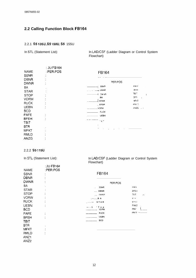
08576655-02
2.2 Calling Function Block FB164
2.2.1 S5 135U, S5 150U, S5 155U
In STL (Statement List):
: JU FB164NAME : PER:POSSSNR :DBNR :DWNR :BASTAR ;STOP :VORW :RUCK :UEBN :BCDPAFE :BFEH :TBITBTRMFKT ;RMLD :ANZG :
2.2.2 S5 115U
In STL (Statement List):
:JU FB164NAME :PER:POSSSNR :DBNR :DWNR :BASTAR ;STOP :VORW :RUCK :UEBN :BCDPAFE :BFEH :TBITBTRMFKT ;RMLD :ANZIANZ2
In LAD/CSF (Ladder Diagram or Control SystemFlowchart)
FB164~–..-
1PER:POS
.—+ SSNR
_ _ . _...+ DBNR
—~ DwNR
.; BA
.-—––..–fl STAR
.: STOP
VORW
—:1 RuCK
–.—..1 UEBN
4 ‘ c ”
PAFE ;
BFEH
TBIT ;
BTR ,
MFW
RMLD
ANZG . -
I
~ . _ _ . . .
In LAD/CSF (Ladder Diagram or Control SystemFlowchart)
FB164
; SSNR
–., OBNR
.-q DWNR
. .– . . . . l B A
_ . . . — S T A R
— - 1 ‘ T o p--—l VORW
—1 RUCK
—--1 UEBN
_.—.J Eico
PER:POS
PAFE
8FEH
TBIT ,-.
BTR
MFK?
RMLD ,-------
ANZ1 ~-—
ANZ2 ~ - - - - - - -
12
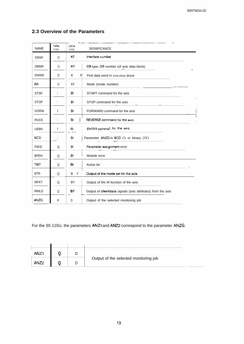
1
B8576655-02
2.3 Overview of the
NAME
SSNR
DBNR
DWNR
STSR
STOP
VORW
RUCK
UEBN
BCD
PAFE
BFEH
TBIT
BTR
MFKT
RMLD
ANZG
3ARA
TYPE
D
D
D
D
I
I
I
I
I
I— .—
Q
Q
Q
Q
Q
Q
0
OATAIYPE
Parameters
.SIGNIFICANCE
KF I Interfacenurnber
w DB type, DB number (of axis data block)— -:
1K F First data word in axis data block
IKF Mode (mode number)
...— ——..—.
BI START command for the axis
IBI STOP command for the axis
II
— — — ,
IBI FORWARD command for the axis
+
BI I REVERSEcommandfortheaxis I
I ENTER ~ommand for the axis:. L..—___
BI ~ Parameter ANZG in BCD (’1 or binary (’O’)——––~—–—
I Parameter assignment error
-L’BI I Module error
i
BI Active bit-
B Y I Outputofthemodesetfortheaxis
BY Output of the M function of the axisI
--LBY Output of checkback signals (axis attributes) from the axis
D Output of the selected monitoring job
For the S5 115U, the parameters ANZ1 and ANZ2 correspond to the parameter ANZG.
I
!
I ANZI Q DOutput of the selected monitoring job
ANZ2 Q D
B8576655-02
2.4 Explanation of the Parameters
SSNR : D,KF X
Specification of the page number (cf. switch setting J64, “Hardware, Instructions”, Section 3,2“Setting the Module Address”) of the corresponding axis,
x = interface (page number)O < = x < = 255
DBNR : D,KY X,y
Specification of the data block type and the data block number of the axis data block. With theS5 115U and S5 150U programmable controllers, data block type DX cannot be programmed.
x = data block typex = O : data block type DBx >< 0 : data block type DX
Y = data block number5 < = y < = 255 where x = 01 < = y < = 255 where x >< 0direct parameter assignment via the block parameters(axis data block)
y=o
indirect parameter assignment via the data blockopened before the FBI 64 call
DWNR : D,KF X
Specification of the first data word in the axis data block,
x = first data wordO < = X < = 236
where:5 < = parameter DBNR < = 163 and166< = parameter DBNR < = 255
16 < = X < = 236where: parameter DBNR = 164
(DB164 = working DB for standardfunction block FB164)
48< = X < = 2 3 6where: parameter DBNR = 165
(DB165 = working DB for standardfunction block FB165)
14
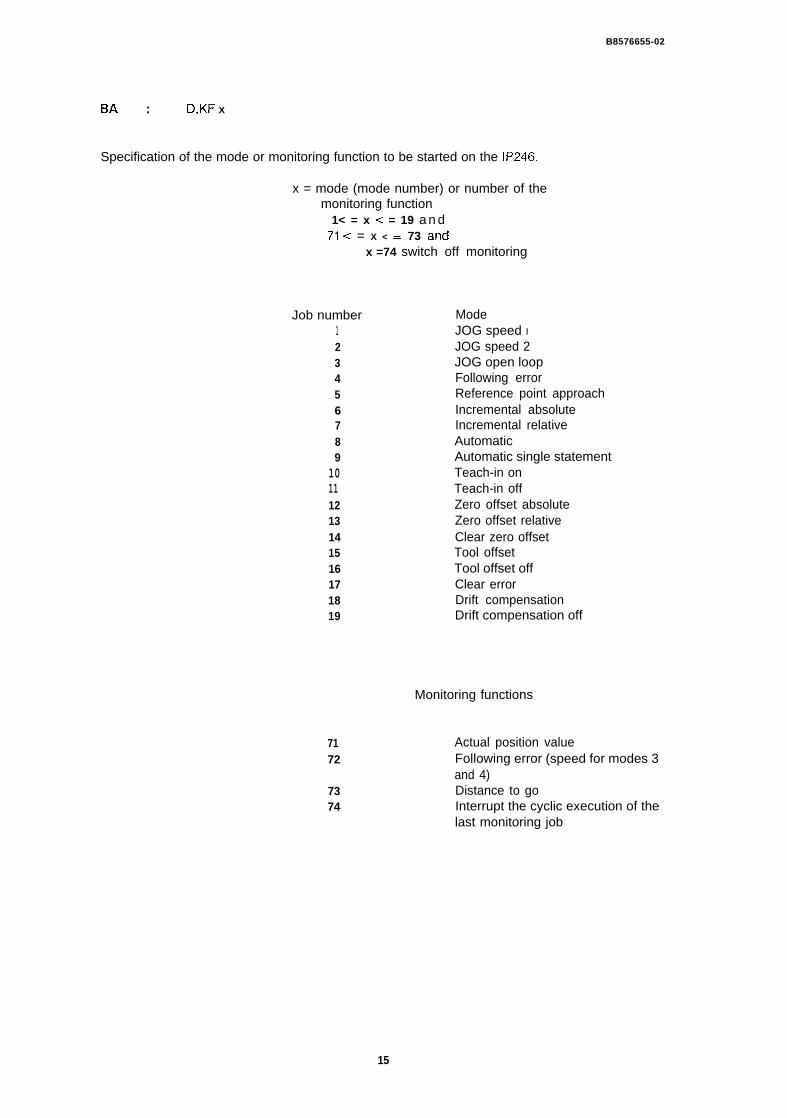
B8576655-02
BA : D,KF X
Specification of the mode or monitoring function to be started on the IP246.
x = mode (mode number) or number of themonitoring function
1< = x < = 19 a n d7’1 < = X < = 73 and
x =74 switch off monitoring
Job number123456789
10111213141516171819
7172
7374
ModeJOG speed IJOG speed 2JOG open loopFollowing errorReference point approachIncremental absoluteIncremental relativeAutomaticAutomatic single statementTeach-in onTeach-in offZero offset absoluteZero offset relativeClear zero offsetTool offsetTool offset offClear errorDrift compensationDrift compensation off
Monitoring functions
Actual position valueFollowing error (speed for modes 3and 4)Distance to goInterrupt the cyclic execution of thelast monitoring job
15
B8576655-02
STAR : I,BISTOP : I,BIVORW : I,BIRUCK : I,BIUEBN : I,BI
These parameters represent the possible commandsand start the data transfer to the positioningmodule on the positive-going edge O --> 1.The following data from the axis data blockare transferred:
● byte parameters (DR n),● word parameters (DW n + 1 ) and● double word parameters (DD n +3)
BCD : I,BI
If the BCD parameter has the signal state “1”, the variables actual position value, following erroror speed and distance to go are converted to a seven digit BCD number with sign. If the signalstate is “O”, these values are output in binary.
In the BCD format a maximum +/- 9999999 (urn, 0.0001 in, 0.001 degrees) can be represented,If one of these limits is violated, the output value (parameter output ANZG or the correspondingdata words) is output as a binary number.
PAFE : Q,BI
If an error is made in the parameter assignment, the PAFE parameter has the signal state “1”. Theerror can be identified by the assignment of
flag byte FY255
(= > “plannin9, Installation and SeNice, Section 2 “Troubleshooting”).
BFEH : Q,BI
The parameter BFEH (module error) has signal state”1” when the IP246 positioning modulesignals an error. The type of error can be identified from
flag byte FY254
(= > “plannin9, Installation and Service, Section 2 “Troubleshooting”).
16
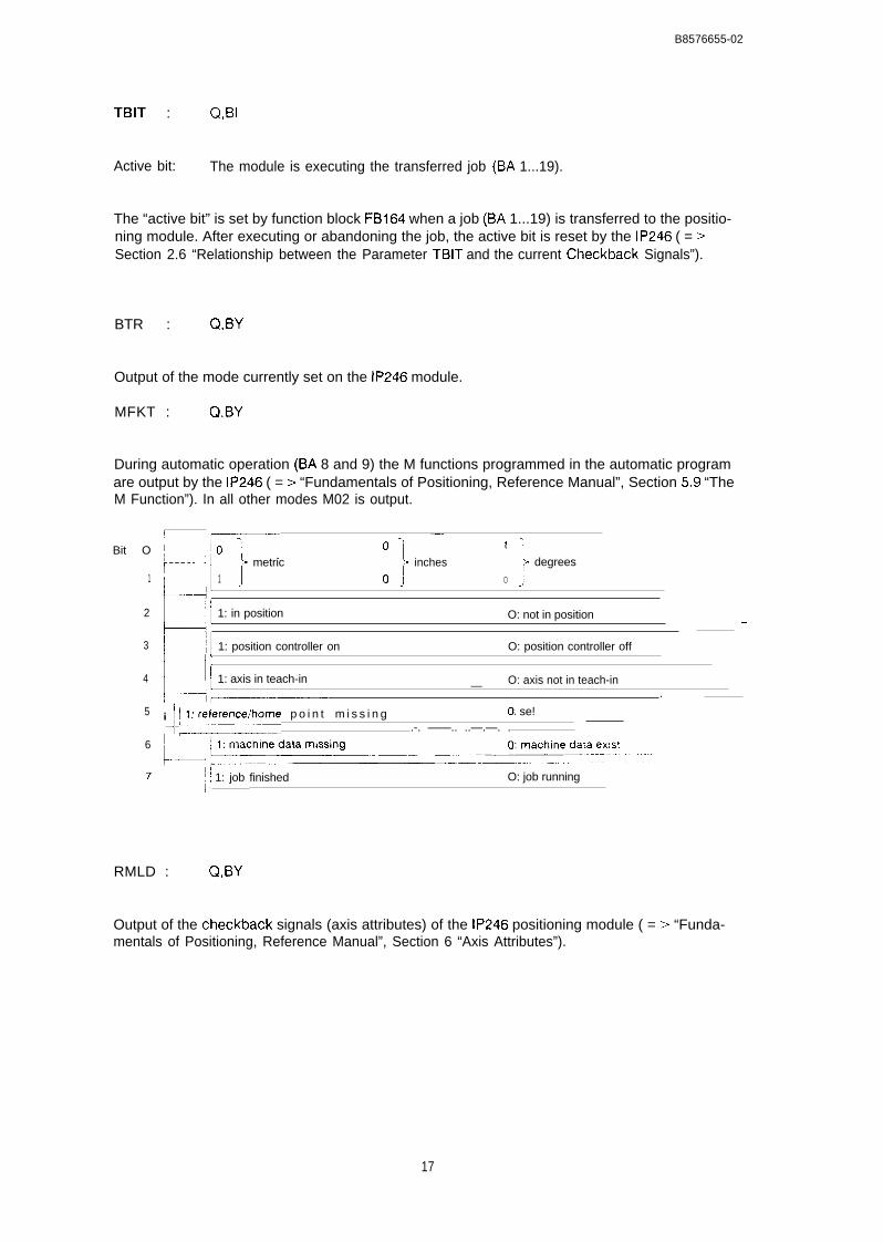
B8576655-02
TBIT : Q,BI
Active bit: The module is executing the transferred job (BA 1...19).
The “active bit” is set by function block FB164 when a job (BA 1...19) is transferred to the positio-ning module. After executing or abandoning the job, the active bit is reset by the IP246 ( = >Section 2.6 “Relationship between the Parameter TBIT and the current Checkback Signals”).
BTR : Q*BY
Output of the mode currently set on the IP246 module.
MFKT : Q,BY
During automatic operation (BA 8 and 9) the M functions programmed in the automatic programare output by the IP246 ( = > “Fundamentals of Positioning, Reference Manual”, Section 5.9 “TheM Function”). In all other modes M02 is output.
Bit O
1
2
3
4
5
6
7
! —-~ W o
~------- ‘= }1 ;
III J metric inches
1
degrees
k,
1 oJ o
L-! 1: in position O: not in position J
u 1: position controller on O: position controller off
Ml 1: axis in teach-in O: axis not in teach-in—~— .
, ~ ~fl:rence/home p o i n t m i s s i n gi ’ 0: se!.-. ——.. ..—.—. .
~ i: ~ 1: job finished,, O: job running
L. ....—2
RMLD : Q,BY
Output of the checkback signals (axis attributes) of the IP246 positioning module ( = > “Funda-mentals of Positioning, Reference Manual”, Section 6 “Axis Attributes”).
17
138576655-02
ANZG : Q,D with S5 115U: ANZ1 : Q,WANZ2 : Q,W
Output of the actual position value (BA 71 set), the following error or speed (BA 72 set) and thedistance to go (BA 73 set). If cyclic monitoring is switched off with mode 74, the value zero isoutput.
The output is either in BCD format (BCD = signal state “l”) or binary (BCD = signal state “O”).
If parameters are assigned indirectly the following output parameters of FB164 are no longerupdated:
BTR mode typeMFKT ~ M functionsRMLD . checkback signal (axis attributes)ANZG - display of the monitoring job
The updated values must then be taken from the axis data block,
In the axis data block (parameter DBNR) only the value selected with modes 71...73 is updated.The other values are deleted (KHOOOO).
2.5 Notes on using Actual Operands
The designations STAR (I,BI), STOP (I,BI), VORW (I,BI), RUCK (I,BI), UEBN (I,BI) and PAFE(Q, BI), BFEH (Q,BI) and TBIT (Q,BI) must not be occupied by the “scratchpad flags”,
The designations BTR (Q, BY), MFKT (Q, BY), RMLD (Q, BY) and ANZG (Q, D) or ANZI (Q,W) andANZ2 (Q,W) must also not be occupied by the scratchpad flags used by function block FBI 64(= > Section 2.8 “Technical Data of FB16411).
When specifying data bytes, data words or a data double word, the information is stored in theaxis data block. Make sure that the axis data area for a particular axis is not overwritterl,
18
B 8 5 7 6 6 5 5 - 0 2
2.6 Relationship between the Parameter TBIT and the current CheckbackSignals
2.6.1 General
A currently active job on the IP246 (BA 1...19) can be scanned for status “running” at parameteroutput TBIT. The parameter should be scanned when a change in the checkback signals (para-meter RMLD) “axis in position” or “job finished” can no longer be detected owing to the cycletime of the user program ( = > “Fundamentals of Positioning, Reference Manual”, Section 6 ‘“AxisAttributes”).
With very short travel distances, e.g. in mode 7 “incremental relative” or with zero point offsets ortool length offsets, the new position could be reached (“position reached”), or the job alreadyexecuted (“job finished”) without a signal change at the appropriate bit in the checkback signalsbeing visible.
If the parameter TBIT is used to start the next job, this can be achieved on each falling edge ofthe parameter. It is, however, not absolutely necessary that the parameter TBIT has the signalstate “O” to start the next job. The parameter TBIT does not have the signal state “O” e.g. when acurrent job is abandoned (mode 1...19) or when an override change takes place (entercommand). The parameter TBIT is not influenced by override changes.
Each time a job is triggered (mode 1,,,19 with command), the parameter TBIT is set by FBI 64.The job (mode with command) is either allowed at this point or is not allowed. If the job isallowed, parameter TBIT is reset by the IP246 on completion of the job. For resetting parameterTBIT, the same conditions apply as for the axis attributes “position reached” or “job finished’ inthe checkback signals ( = > “Fundamentals of Positioning, Reference Manual”, Section 6 AxisAttributes”), If the job is not permitted at the present time or the command is not permitted withthe current mode, any active job will be abandoned. The parameter TBIT is then reset after thejob has been abandoned. If there is no job currently running (bit 7 in the checkback signalsRMLD is set to”1” = ‘(job finished”), parameter TBIT is reset again by the IP246 immediately.
2.6.2 The Parameter TBIT with the individual Modes
The following diagrams are not to scale and do not take into account the cycle time of the userprogram and the IP246.
19

JOG speed 1 (mode 1)JOG speed 2 (mode 2) andJOG open loop (mode 3)
STOP
UEBN~–-–:
——— —.— .-d —.
TBIT..–l””---”-—----””-— {
t
If an override change takes place while the axis is moving, this does not affect TBIT
Mode following error (mode 4)
START
STOP1
TBIT ~ - 7:-..—-
t
Mode —. reference/home point (mode 5)
home po, nt
m(ssmg
TBIT
//’
run run
STOP
/
..J L—. -– .———..—.
set,/,,/
+–—
..! .
\ . . t
B 8 5 7 6 6 5 5 - 0 2
Mode — incremental absolute (mode 6) and— incremental relative (mode 7)
START orm L -
,-—FWD/REV
,
- j
STOP1
UEBN -.~L_..–—.——
Mode — automatic (mode 8)
~—-l.—.——.—
START ,,— . -.— ——-—-—-– .---— -——–— -- . . .- —.. —..— ..-. .. ——...———-.—.
STOP.——. ..—.—.— .. —- —. —..
;—----TBIT I
- I Program tetmnated
M02
. . t
Mode automatic single statement
START.--.-.-.._L-...-..n
STOP –.---–A-L—
(mode 9)
UEBN_ _ ~ . . r L . . - . . . - . . l n
Traversing1 St ,~~,~~~”~ ~, 2nd Traversing 3rd
Traversing statementstatement or or dwell hme
dwell time dwell time - t
With the enter command (U EBN), the next statement of the automatic program (traversing job ordwell time) is started. If there is a stop between two statements in “automatic single statement”operation, the parameter TBIT is also set by FBI 64 and reset by the IP246.
21
08576655-02
Mode — teach-in on (mode 10) and— teach-in off (mode 11)
UEBN
Teach-m ofl stan... ..———../,
The parameter TBIT is reset by the IP246 after storing the position (IJEBN) or on termination(STOP) of the teach-in. In teach-in, various positions can be approached, e.g. in incremental ap-proach or in the JOG mode. The conditions explained for these modes also apply to the parame-ter TBIT,
Mode — zero offset absolute (mode 12),zero offset relative (mode 13),
— clear zero offset (mode 14),— tool offset (mode 15),
tool offset off (mode 16) and— clear error (mode 17)
START or -- —....—I IFWDIREV _...—.A L—.-.–.——
TBIT~——..—,I ,
—1 L – – . — - – . – . — . . . — — — – . — . — . . . —
-t
The parameter TBIT remains set until the mode is complete. These modes cannot be aborted
Mode drift compensation (mode 18)
STOP —.._—
I ~- L . . . . . — – — - .-——..—. -
TBITI
—“’-—~,-
1.— — . — – l ~—~,
Compensation value calculated
- t
The parameter TBIT remains set until the mode is complete. The drift compensation mode canbe aborted by a stop command
22
B 8 5 7 6 6 5 5 - 0 2
Mode — Drift compensation off (mode 19)
“tThe parameter TBIT remains set until completion of the mode. This mode cannot be aborted
2.7 Data Area Requirements
The standard function block FBI 64 works with data block DB1 64. It requires data words DW8 toDW15 as its working area.
An axis data block must be specified using the parameter DBNR. This data block is used for thefollowing:
——
2.7.1
to store the monitoring values, checkback signals, M functions etc. read from the IP246for indirect assignment of parameters (DW1 to DW7) to the function block FBI 64 arlcito store the data required for the mode to be started.
Indirect Assignment of Parameters to FB164
It is possible to assign parameters to the function block FB164 indirectly. The value
KY 0,0
must be preset as the actual operand for parameter DBNR, With this assignment, FB164 takesthe values for its parameters from the data block valid before its call,
All permitted data blocks can be used. Even data block DB164 or the axis data block would bepossible,
Indirect parameter assignment requires data words DW1 to DW7 of the data block inclusive;these data words have a fixed assignment. When using DB164, this does not lead to conflicts,since FBI 64 uses DWEt to DW15 inclusive as its working area. If the axis data block was openbefore FB164 was called, you must enter at least the value 8 in DW5 (parameter DWNR) as thefirst data word to make sure that the data for indirect parameter assignment are not overwritten.
23
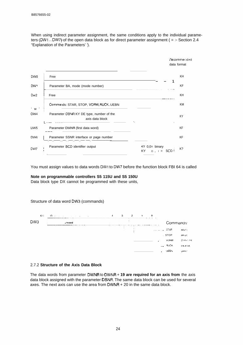
B8576655-02
When using indirect parameter assignment, the same conditions apply to the individual parame-ters (DW1 ,,, DW7) of the open data block as for direct parameter assignment ( = > Section 2.4“Explanation of the Parameters’ ().
Recommerided
data format
DWO I Free IKH
— — 1DW1
I
Parameter BA, mode (mode number) I KF–——––—---
Dw2 I Free KH—-4
Commands: STAR, STOP, VORW, RUCK, UEBN‘ w ’ +
KM
DW4 ; Parameter DBNR KY DE type, number of theI KY
axis data blockL - — - - - - -. .
DW5 ~ Parameter DWNR (first data word) KF,. —.—.—
DW6 I Parameter SSNR interface or page number KF-—.—..——...—. .—-..—-..-— -—. -——————
Parameter BCD identifier outputDW7 ~
KY 0,0= binary IKY O , I = BCD ~
K?
‘ L
You must assign values to data words DW1 to DW7 before the function block FBI 64 is called
Note on programmable controllers S5 115U and S5 150UData block type DX cannot be programmed with these units,
Structure of data word DW3 (commands)
. STOP (slop)
1 . vORW (f O&v~[’35)
-+ RUCK [re.e(se)
~ UEf3N (enter,
2.7.2 Structure of the Axis Data Block
The data words from parameter DWNR to DWNR + 19 are required for an axis from the axisdata block assigned with the parameter DBNR. The same data block can be used for severalaxes. The next axis can use the area from DWNR + 20 in the same data block.
24
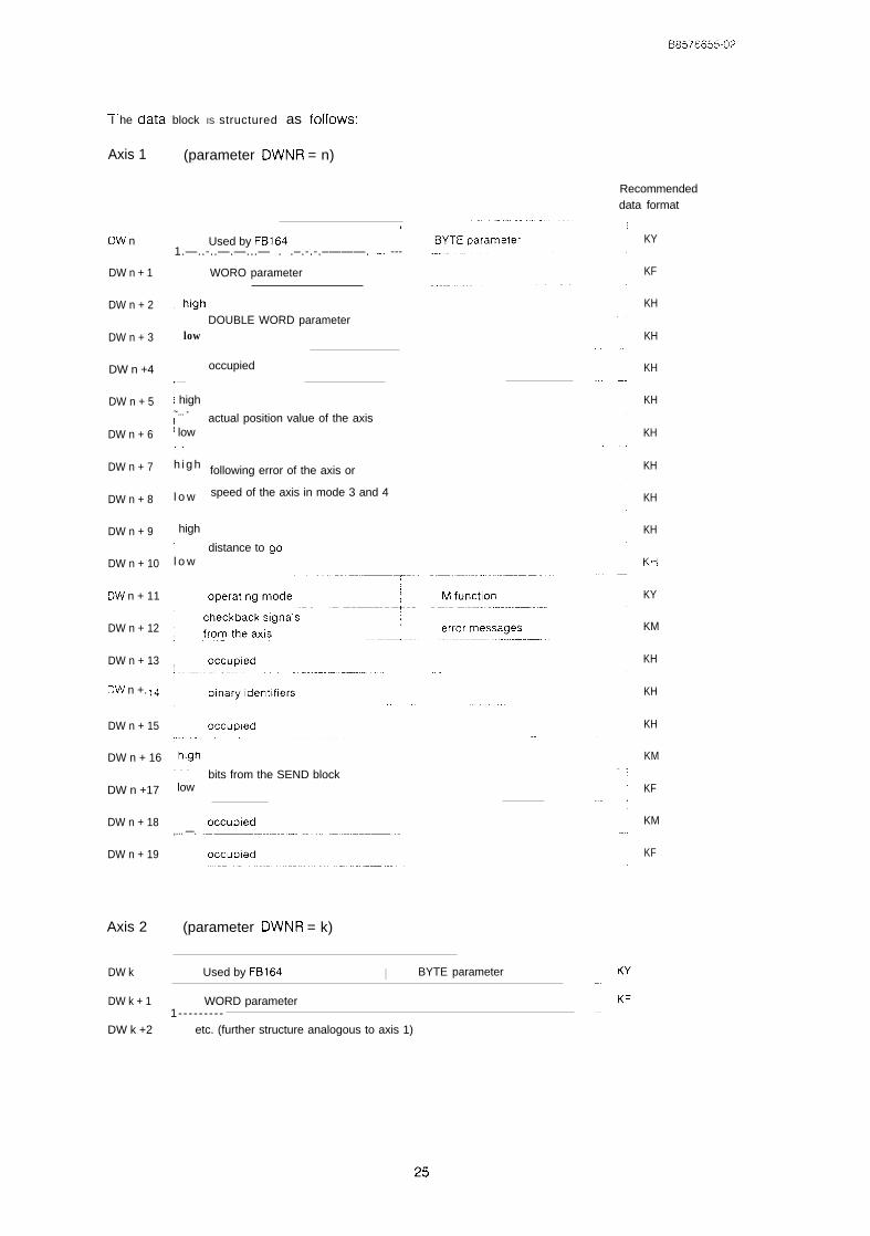
-, . ,,I he data block IS structured as tollows:
Axis 1 (parameter DWNR = n)
Recommendeddata format
ON n
DW n + 1
DW n + 2
DW n + 3
DW n +4
DW n + 5
DW n + 6
DW n + 7
DW n + 8
DW n + 9
DW n + 10
DW n + 11
DW n + 12
DW n + 13
D\/”IJ n +. 14
DW n + 15
DW n + 16
DW n +17
DW n + 18
DW n + 19
Axis 2
DW k
DW k + 1
DW k +2
1
Used by FB1641.—..-..—.—...— . .–.-.-.–———. .-. ---
WORO parameter
lowDOUBLE WORD parameter
occupiedl-–
I high~... -1( low. .
h i g h
l o w
high.—
l o w
actual position value of the axis
following error of the axis or
speed of the axis in mode 3 and 4
distance to go
. . .~ low
,... —.
bits from the SEND block
(parameter DWNR = k)
!
Used by FB164 I BYTE parameter
I WORD parameter1-- - - - - - - -
etc. (further structure analogous to axis 1)
KY
KF
KH
KH
KH
KH
KH
KH
KH
KH
Kti
KY
KM
KH
KH
KH
KM
KF
KM
KF
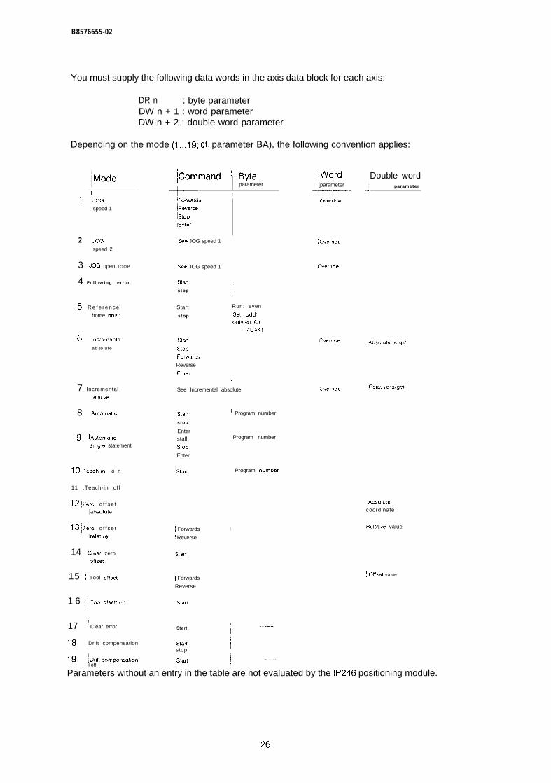
B8576655-02
You must supply the following data words in the axis data block for each axis:
DR n : byte parameterDW n + 1 : word parameterDW n + 2 : double word parameter
Depending on the mode (1,,,19; cf. parameter BA), the following convention applies:
~command ! W@parameter
+ !
Double word
.J parameter[parameter~-—’-—-
1 ~JOG
speed 1
~Fowards~Hever~e
Istop
Enter
Gverride
2 JOG
speed 2
3 ~JOG open IOOP
4 Following error
!See JOG speed 1 ~ (kerride
See JOG speed 1 Ovemde
Star!
stop ~
5 R e f e r e n c e
home cant
Start Run: even
stop Set: odd’Only -4UA31
-4L)A4 1
6 lncrernenta,
absolute
Starl
stopForwards
Reverse
Emer)
Ovemde Fbat, ve larget7 Incremental
,relatlve
8 iA.tomaw
See Incremental absolute
!Start
stop
~Y• Enter‘stall
;Stop
‘Enter
1 Program number
9 IA.tomal(cwngle statement
Program number
10 Teach.,. o n
11 ,Teach-in off
12 ~ZerO o f f s e t
Iabsolute
13 ~ZerO o f f s e t
!helative
14 Clear zero
,olfset
15 i Tool offset
~ Program “umber
Absol.le
coordinate
Relatlve valueI Forwards
! Reverse
I
Slafl
! Offset valueI Forwards
Reverse
1 6 ~ Tool otsett off Stafl
17 ~l Clear error
1!3 Drift compensation
19 !Or’fi’omp-a’o”I off
i Start
iStartstop
~stmt
Parameters without an entry in the table are not evaluated by the IP246 positioning module.
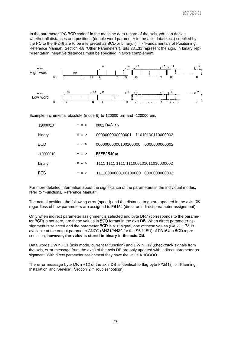
B8576655-02
In the parameter “PC BCD coded” in the machine data record of the axis, you can decidewhether all distances and positions (double word parameter in the axis data block) supplied bythe PC to the IP246 are to be interpreted as BCD or binary. ( = > “Fundamentals of Positioning,Reference Manual”, Section 4.8 “Other Parameters”), Bits 28...31 represent the sign. In binary rep-resentation, negative distances must be specified in two’s complement.
Value:27
2
High word Sign–7&!I!%” “_I’:I %L...L
bit: 3 1 28 2 7 24 23 20 19 16
Value: 215 2
12 z 11
Low word I I ~ L*::iT_...i:_t::::””:””fo:...fo:bit: 15 12 11 8 7 ....,,. 4 3 . . . 9
Example: incremental absolute (mode 6) to 120000 urn and -120000 um.
12000010 .— = > 0001 D4C016
binary ——. > 0000000000000001 11010100110000002
BCD =. > 00000000000100100000 0000000000002
-12000010 —— = > FFFE2B401fj
binary —.= > 1111 1111 1111 111000101011010000002
BCD —— = > 11110000000100100000 0000000000002
For more detailed information about the significance of the parameters in the individual modes,refer to “Functions, Reference Manual”.
The actual position, the following error (speed) and the distance to go are updated in the axis DBregardless of how parameters are assigned to FB164 (direct or indirect parameter assignment).
Only when indirect parameter assignment is selected and byte DR7 (corresponds to the parame-ter BCD) is not zero, are these values in BCD format in the axis DB. When direct parameter as-signment is selected and the parameter BCD is a”1” signal, one of these values (BA 71 ...73) isavailable at the output parameter ANZG (ANZ1/ANZ2 for the S5 115U) of FB164 in BCD repre-sentation, however, the value is stored in binary in the axis DB.
Data words DW n +11 (axis mode, current M function) and DW n +12 (checkback signals fromthe axis, error message from the axis) of the axis DB are only updated with indirect parameter as-signment. With direct parameter assignment they have the value KHOOOO.
The error message byte DR n +12 of the axis DB is identical to flag byte FY251 (= > “Planning,Installation and Service”, Section 2 “Troubleshooting”).
27
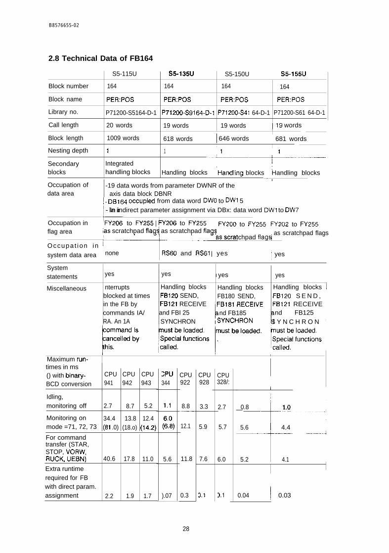
B8576655-02
2.8 Technical Data of FB164
S5-115U S5-135U S5-150U I S5-155U
Block number 164 164 164 164
Block name PER:POS PER:POS PER:POS PER:POS
Library no. P71200-S5164-D-1 P71200-S9164-D-1 P71200-S41 64-D-1 P71200-S61 64-D-1
Call length 20 words 19 words 19 words 119 wordsI
Block length 1009 words 618 words I 646 words ~ 681 words,
Nesting depth 1I
1 : 1~.+.....——.-
1
Secondary Integrated ~blocks handling blocks Handling blocks !Handling blocks ~ Handling blocks
Occupation ofdata area
Occupation inflag area
1
-19 data words from parameter DWNR of theaxis data block DBNR
~- DB164 occupi~ from data word DWO to DW1 5
E
- In indirect parameter assignment via DBx: data word DW1 to DW7
FY20; to FY255 I FY206 to FY255I
I FY200 to FY255 ~ FY202 to FY255ias scratchpad flag~ as scratchpad fla9Si~..—.
~ as scratchpad flagsEm scratchpad flagq
Occupa t ion in Isystem data area none RS60 and RS61 ~ yes ~ yes
Systemstatements yes yes I yes yes I
1Miscellaneous nterrupts Handling blocks Handling blocks Handling blocks I
blocked at times FB120 SEND, FB180 SEND, FB120 S E N D , ~in the FB by FB121 RECEIVE FB181 RECEIVE FB121 RECEIVE ~commands IA/ and FBI 25 k nd FB185
rnd FB125 ~
RA. An 1A SYNCHRON ~ SYNCHRON S Y N C H R O N :
I I I IMaximum run-times in ms() with binary- CPU CPU CPU
BCD conversion 941 942 943
Idling,monitoring off 2.7 8.7 5.2
Monitoring on 34.4 13.8 12.4mode =71, 72, 73 (81 .0) (18.o) (14.2)
For commandtransfer (STAR,STOP, VORW,RUCK, UEBN) 40.6 17.8 11.0
Extra runtimerequired for FBwith direct param.assignment 2.2 1.9 1.7
:Pu344
1.1
(8)
5.6
).07
CPU922
8.8——
12.1
11.8
0.3
CPU928
3.3
5.9
7.6
2.1
CPU328/:
2.7
5.7
6.0
D.1
I
0.8
+--------1
1.0—
5.6 I 4.4~—-- ----------J
I
5.2 4.1 1
0.04 ~ 0.03
28
0 8 5 7 6 6 5 5 - 0 2
2.9 Using Function Block FB164
In cyclic operation it is not possible to address a module both with indirect and direct para-meter assignment.
Function block FBI 64 works with data block DB164. This must be installed up to and includingdata word DW15. A particular assignment of the data words is not necessary.
Data block DB164 is divided into two areas, in which data words DW1 to DW7 are reserved for irvdirect assignment of parameters to the function block. Data words DW8 to DW15 are the workingarea for FB1 64. You must not change the working area.
Before calling FB164, the axis parameters (byte, word and double word parameters) must bewritten to the axis data block (parameter DBNR) as required for the mode to be started. The datablock must be a minimum of x words long, where
x = parameter DWNR +
e.g.: axis 1 : parameter DWNR =axis 2 : parameter DWNR =
If only one axis is required, the data block
19
1 -> x = 2021 -> x = 40
must be available up to and including data word DW20
If axis 1 and axis 2 are used and if the parameters for the axes are contained in one data blockthis must be available up to and including data word DW40. The data block number (parameterDBNR) and the data word number (parameter DWNR; start address in the data block) can be se-lected as required.
The data block is set up with a programmer, e.g. with the PG685 STEP5 under S5-DOS (stage [II)using the following commands (after exiting the presetting mask):
< F1 > (input)< F1 > (block)
Pc (input device)DB160 (b lock ) enter key < I >DW O: KY = 000,000DW 1: KF = +00000DW 2: KH = 0000DW 3: KH = 0000
DW 19: KF = +00000 enter key < I >
The function block FB164 must be called unconditionally once per cycle for each axis. This is ne-cessary in order to update the edge flags of the parameters STAR, STOP, VORW, RUCK andUEBN.
29
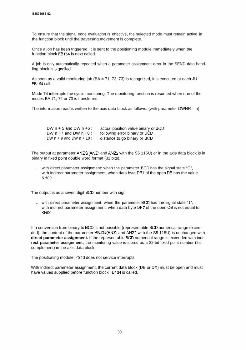
B8576655-02
To ensure that the signal edge evaluation is effective, the selected mode must remain active inthe function block until the traversing movement is complete.
Once a job has been triggered, it is sent to the positioning module immediately when thefunction block FB164 is next called.
A job is only automatically repeated when a parameter assignment error in the SEND data hand-ling block is signalled.
As soon as a valid monitoring job (BA = 71, 72, 73) is recognized, it is executed at each JUFB164 call.
Mode 74 interrupts the cyclic monitoring. The monitoring function is resumed when one of themodes BA 71, 72 or 73 is transferred.
The information read is written to the axis data block as follows: (with parameter DWNR = n):
DW n + 5 and DW n +6 : actual position value binary or BCDDW n +7 and DW n +8 : following error binary or BCDDW n + 9 and DW n + 10 : distance to go binary or BCD
The output at parameter ANZG (ANZ1 and ANZ2 with the S5 115U) or in the axis data block is inbinary in fixed point double word format (32 bits).
— with direct parameter assignment: when the parameter BCD has the signal state “O”,with indirect parameter assignment: when data byte DR7 of the open DB has the valueKHOO.
The output is as a seven digit BCD number with sign
— with direct parameter assignment: when the parameter BCD has the signal state “1”,with indirect parameter assignment: when data byte DR7 of the open DB is not equal toKHOO.
If a conversion from binary to BCD is not possible (representable BCD numerical range excee-ded), the content of the parameter ANZG (ANZ1 and ANZ2 with the S5 115U) is unchanged withdirect parameter assignment. If the representable BCD numerical range is exceeded with indi-rect parameter assignment, the monitoring value is stored as a 32-bit fixed point number (2’scomplement) in the axis data block.
The positioning module IP246 does not service interrupts
With indirect parameter assignment, the current data block (DB or DX) must be open and musthave values supplied before function block FB164 is called.
30
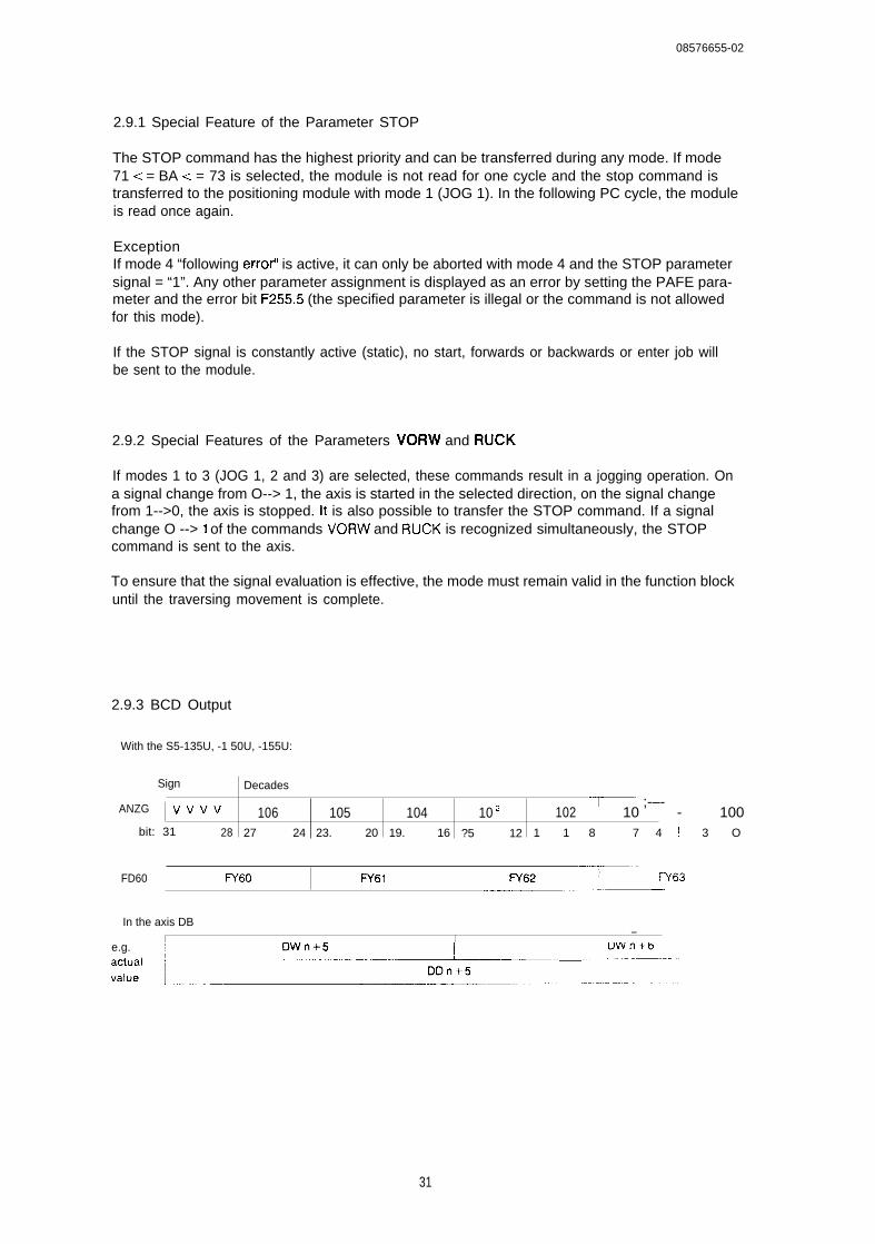
08576655-02
2.9.1 Special Feature of the Parameter STOP
The STOP command has the highest priority and can be transferred during any mode. If mode71 < = BA < = 73 is selected, the module is not read for one cycle and the stop command istransferred to the positioning module with mode 1 (JOG 1). In the following PC cycle, the moduleis read once again.
ExceptionIf mode 4 “following errot’ is active, it can only be aborted with mode 4 and the STOP parametersignal = “1”. Any other parameter assignment is displayed as an error by setting the PAFE para-meter and the error bit F255.5 (the specified parameter is illegal or the command is not allowedfor this mode).
If the STOP signal is constantly active (static), no start, forwards or backwards or enter job willbe sent to the module.
2.9.2 Special Features of the Parameters VORW and RUCK
If modes 1 to 3 (JOG 1, 2 and 3) are selected, these commands result in a jogging operation. Ona signal change from O--> 1, the axis is started in the selected direction, on the signal changefrom 1-->0, the axis is stopped. it is also possible to transfer the STOP command. If a signalchange O --> 1 of the commands VORW and RUCK is recognized simultaneously, the STOPcommand is sent to the axis.
To ensure that the signal evaluation is effective, the mode must remain valid in the function blockuntil the traversing movement is complete.
2.9.3 BCD Output
With the S5-135U, -1 50U, -155U:
Sign Decades
ANZG Vvvv “~” ;-–-106 105 104 10 s 102 10 - 100~
bit: 31 28 27 24 23. 20 19. 16 ?5 12 1 1 8 I 7 4 ! 3 O
-—.. -FD60 I FY60 IV61 I FY63
.--—w~—
In the axis DB—
Ie.g. DW n +5 DW n +6
:::: ~.._:EJ+L._.... _.....-T”” ““’
31

B8576655-02
2.9.4 BCD Output with the S5 115U
Parameter ANZ1
Parameter ANZ2
Sign Decades..—.—.—..————... ,
I Vvvv ] 10,, 6-–-bit 1 5 . . , 12 ~ 11,.. 8
Decades
I 10 3 4—:.!? --:-. . . . . .bit 15,. . 12 1 1 . . . 8
32

138576655-02
3 Standard Function Block FB165
3.1 Functional Description
The function block “assigning parameters to the positioning module” handles the data exchangebetween the user program and the IP246 positioning module. Each valid job number causes adata transfer IP246 < = = = > PC.
Data exchange PC = = = > IP246:The data to be transferred is located in a data block of your choice (source DB). Withdirect parameter assignment, the data block must be planned at the block parameters ofFB165, with indirect parameter assignment, in the axis data block.
Data exchange IP246 = = = > PC:The data to be read from the IP246 positioning module is stored in a data block in thePC memory (destination DB). With direct parameter assignment, this data block must beplanned at the block parameters of FB165 and with indirect parameter assignment in theaxis data block.
The following functions are possible via the PC interface using FB165:
— read machine data and machining programs from the IP246, delete and transfer thelm,— read the SYSID from the IP246 (BA 70) and transfer them to the IP246 (BA 24),— request an overview of machine data or machining programs stored on the IP246 and
read actual values (actual position value, following error or speed, distance to go)simultaneously.
The function block FB165 can have parameters assigned directly or indirectly. With direct para-meter assignment, the data and parameters for a job are applied to the parameter inputs ofFBI 65. With indirect parameter assignment, the axis data block is planned in the data block validbefore its call. The remaining parameters are taken byFB165 from the axis data block.
Before FB165 is called, the axis data block must be set up and with indirect parameter as-signment must be supplied with the values required to start the mode.
33
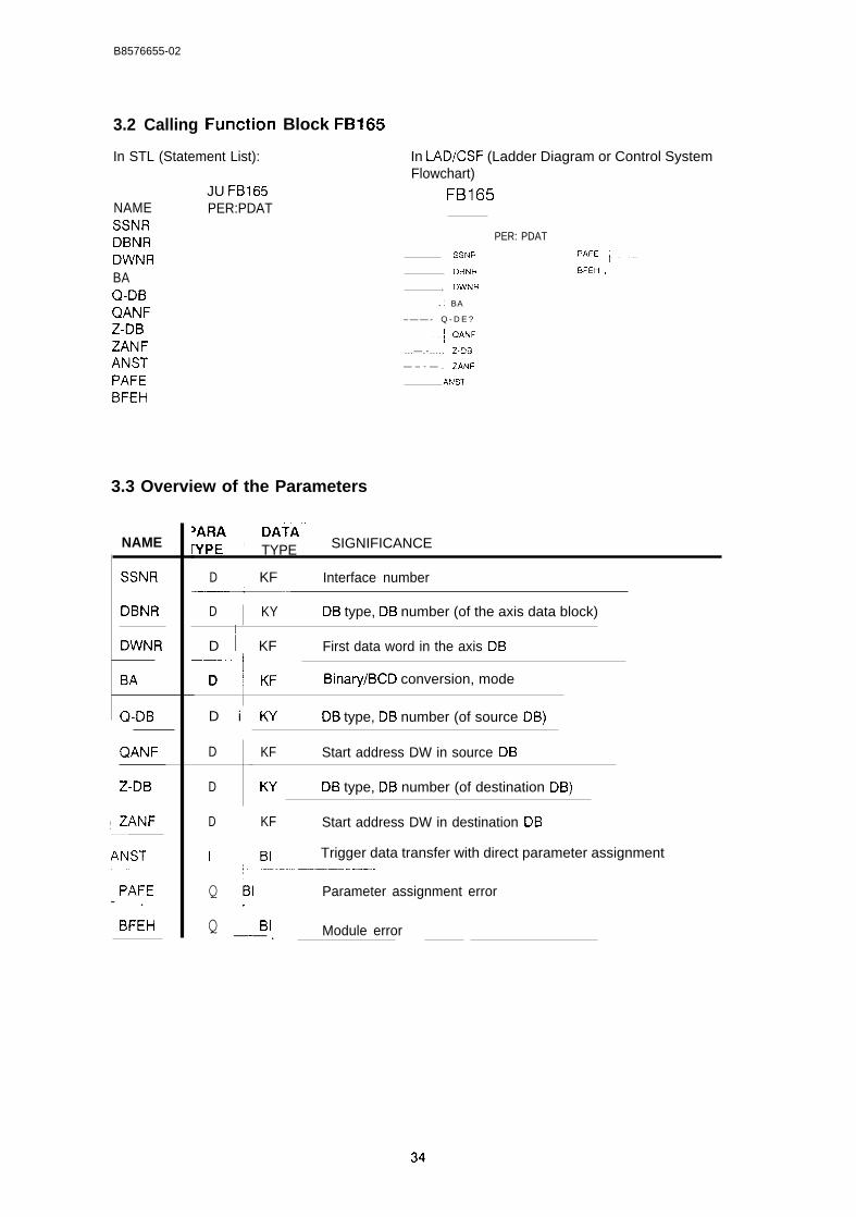
B8576655-02
3.2 Calling
In STL (Statement List):
NAMESSNRDBNRDWNRBAQ-DBQANFZ-DBZANFANSTPAFEBFEH
JU FB165PER:PDAT
Block FB165
In LAD/CSF (Ladder Diagram or Control SystemFlowchart)
FB165
PER: PDAT
SSNR PAFE }-–—
DBNR BFEH -–- -..-—
, DwNR
.; BA
– — — - Q - D E ?
-.-j QANF
...—.-. . . . . Z.DB
— – - — . ZANF
ANST
3.3 Overview of the Parameters
NAME
SSNR
DBNR
DWNR
BA
Q-DB
QANF
Z-DB
-—
ANST;-------
~ PAFE- .
~ BFEH
5ARA ~ DATA””WPE I TYPE SIGNIFICANCE
1D ~ KF Interface number
—*--D KY DB type, DB number (of the axis data block)
D I KF First data word in the axis DB--*
D Binary/BCD conversion, modeI
D i K’f DB type, DB number (of source DB)
D
D
D
I
KF Start address DW in source DB
KY
KF
BI
DB type, DB number (of destination DB)
Start address DW in destination DB
Trigger data transfer with direct parameter assignment
Q BI Parameter assignment error.
Q ~ BI Module error—-— . –—
B8576655-02
3.4 Explanation of the Parameters
SSNR : D,KF X
Specification of the page number (cf. switch setting J64, “Hardware, Instructions”, Section 3.2“Setting the Module Address”) of the appropriate axis.
x = interface (page number)
O < = X < = 255
DBNR : D,KY X,y
Specification of the data block type and data block number of the axis data block. With the pro-grammable controllers S5 115U and S5 150U it is not possible to program the data block typeDX,
x = data block type
x = O : data block type DBx >< 0 : data block type DX
Y = data block number
5C = y < = 255 where x = O1 < = y < = 255 where x >< 0direct parameter assignment via the block parameters
y=o
indirect parameter assignment via the data block opel Ibefore the FB165 call
DWNR : D,KF X
Specification of the first data word in the axis data block.
x = first data word
0< = X < = 241where: 5< = parameter DBNR < = 163 and
166< = parameter DBNR < = 255
48< = X < = 2 4 1where: parameter DBNR = 165
(DB165 = working DB for FB165)
16< = X < = 2 4 1where: parameter DBNR = 164(DB164 = working DB for standard function block FB164)
35
B8576655-02
BA : D,KY X,y
Specification of the mode to be executed, selection binary/BCD conversion.
x = O : no binary/BCD conversionx >< O: binary/BCD conversion of actual positionvalue, following error (or speed) and distance to go.Evaluation only in mode BA 66.
Y = operating mode (job number)
20< = y < = 24 write and delete jobs
64< = y < = 70 read jobs
Job number Operating mode
20 input machine data *one axis21 delete machine data *one axis22 input machining program *both axes23 delete machining program *both axes24 input SYSID *both axes64 read machine data directory *both axes65 read machining program directory *both axes66 read actual values *one axis67 read machine data *one axis68 read machine data overview *both axes69 read machining program *both axes70 read SYSID *both axes
Q-DB : D,KY X,y
Specification of the source data block. For the programmable controllers S5 115U and S5 150Uit is not possible to program data block type DX,
x=
Y =
data block type
x = O : data block type DBx ><0 : data block type DX
source data block number
1 c = y < = 255in modes 20, 22 and 24 (write jobs)the specified data block (source DB)is in the PC memory.
O < = y -= = 255in modes 67 and 69 (read jobs)the specified data block (source DB)is in the RAM of the positioning module.
36

38576655-02
QANF : D,KF X
Specification of the first data word from which the data is to be read out of the specified sourceDB.
x = source first data word
O<=x<=n
a source first data word is only required for modes 20,22 and 24 (write jobs)
(n = max. 2047 words; max. data block length, theadvisable range is between O and 255)
Z-DB : D,KY X,y
Specification of the destination data block, For the programmable controllers S5 1 15U and S5150U it is not possible to program the data block type DX,
x = data block type
x = O : data block type DBx >< 0 : data block type DX
y = destination block number
1 < = y < = 255for modes 64 to 70 (read jobs)the specified data block (destination DB)is in the PC memory.
O < = y < = 255for modes 20 to 23 (write and delete jobs)the specified data block (destination DB)is in the RAM of the positioning module.
ZANF : D,KF X
Specification of the first data word from which data will be written to the specified destination DB
X = destination first data word
O<=x<=n
a destination first data word is only required formodes 64 to 70 (read jobs)
(n = max. 2047 words: max. data block length,the advisable range is between O and 255)
37
B8576655-02
ANST : I,BI
When assigning parameters via the block parameters (direct parameter assignment) the pendingjob is executed on a signal change from “O” to”1” at the ANST parameter. You must set the para-meter. If the job (mode) has been completed, the parameter is reset by the function block FBI 65(acknowledged).
PAFE : Q,BI
The parameter PAFE has the signal state”1” if the parameter assignment is incorrect. The errorcan then be identified in
flag byte FY255
(=> “planning, Installation and Service”, Section 2 “Troubleshooting”).
BFEH : Q,BI
The parameter BFEH (module error) has signal state”1” when an error is signalled by the positio-ning module. The error can be identified in
flag byte FY254
(= > “planning, Installation and Service”, Section 2 “Troubleshooting”).
3.5 Notes on using Actual Operands
The parameters ANST (I,BI), PAFE (Q,BI) and BFEH must not be occupied by the “scratchpadflags” of function block FB165 (see technical data).
38
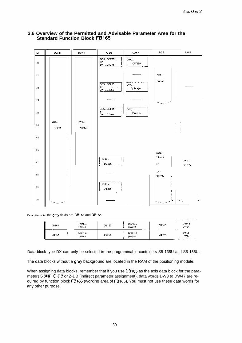
E18576655-02
3.6 Overview of the Permitted and Advisable Parameter Area for theStandard Function Block FB165
w
20
21
22
23
24
64
65
66
67
68
59
70
DBNR
DB5...
DB255
‘~
DwNR
Dwo...
DW241
Q-DB
I
I III DB255 I iL—-
Z.DB ZANF
DBo...
DB255
~---”
DB5...
DB255
or
DX1
—-.
Dx255 ~
))
J
DWO...
\ D’W255
I<.
I
I
I.>
Exceptions in the grey fields are DB164 and DB165:_.. . . . . .
I I DW48...{
DB165
t
DB165~ :;;:l.
DB165DW48
DW241-—
DW241~‘—’”” .,.
1DB164
D W 1 6DB164
D W 1 6DB164
DW16DW241
IDW241 ! DW241
. 1 . - . .
Data block type DX can only be selected in the programmable controllers S5 135U and S5 155U.
The data blocks without a grey background are located in the RAM of the positioning module.
When assigning data blocks, remember that if you use DB165 as the axis data block for the para-meters DBNR, Q-DB or Z-DB (indirect parameter assignment), data words DW3 to DW47 are re-quired by function block FB165 (working area of FB165). You must not use these data words forany other purpose.
39
B8576655-02
3.7 Data Area Requirements
The standard function block FB165 works with data block DB165. It requires data words DW3 toDW47 inclusive for its working area.
An axis data block must be specified using the parameter DBNR. A job field with a length of 15data words must be available in this axis data block for each axis.
3.7.1 Indirect Assignment of Parameters to FB165
It is possible to assign parameters to the function block FB165 indirectly. The parameter DBNRmust have the
value KY 0,0
set as the actual operand. FBI 65 then obtains the parameters DBNR and DWNR from the datablock open before its call. The remaining input parameters are supplied from the specified axisdata block.
Any permitted data block can be used, Even data block DB165 or the axis data are possible
Indirect parameter assignment requires data words DW1 and DW2 of the open data block.
When using DB165, conflicts do not arise, since FB165 uses DW3 to DW47 as its working area. Ifthe axis data block is open before FB165 is called, you must enter at least the value 3 in DW2 (pa-rameter DWNR) as the first data word, to ensure that the data are not overwritten when using indi-rect parameter assignment.
Structure of the data block with indirect parameter assignment,Recommendeddata format
r —.
‘Wok ‘ KH
DW1 Parameter DBNR KY DB type, DB number ,’W
& - - -of the axis data block
.–-+DW2 I Parameter DWNR (first data word) ~ KFJ
You must supply values for DW1 and DW2 when using indirect parameter assignment beforefunction block FB165 is called.
The DB type (DL1) and DB number (DR1) define the axis data block, The DW number (DW2) indi-cates the start of the job field of the job to be executed in the axis data block.
40
B 8 5 7 6 6 5 5 - 0 2
3.7.2 Structure of the Axis Data Block for an Axis
The data words from parameter DWNR to DWNR +14 inclusive are required for an axis from theaxis data block selected with the parameter DBNR. The same data block can be used for severalaxes, the next axis then occupies the area from DWNR + 15.
The data block is structured as follows:
Axis 1
DW n
DW n + 1
DW n + 2
DW n + 3
DW n + 4
DW n + 5
DW n + 6
DW n + 7
DW n + 8
DW n + 9
DW n + 1 [
DW n +11
DW n + 1 Z
DW n + l:
DW n + 14
(Parameter DWNR = n)Recommendeddata format
Parameter BA; binary/BCD conversion (only BA 66), op. mo
Parameter Q-DB; DB type, source data block
Parameter QANF; source first data word
Parameter Z-DB; DB type, destination data block
Parameter ZANF; destination first data word
Parameter SSNR; interface number
binary identifiers
high
,Ow bits from the SEND block..-
-.
occupied
occupied
high— bits from the FETCH blocklow
occupied
occupied
—
There must be a “job field” with this structure for each axis addressed.
KY
KY
KF
KY
KF
KF
KY
KM
KF
KM
KF
KM
KF
KM
KF
The data words DWn to DWn + 5 inclusive must only be completed if the function block is tohave parameters assigned indirectly.
41

B8576655-02
The data words DWn + 6 to DWn + 14 are used by function block FBI 65 and you can only readthem, E.g. evaluation of the interface in the high byte of the condition code bytes:
DL n + 7 and DL n + 11: High byte of the condition codeword. Corresponds to flag byte FY250.
With indirect parameter assignment, you enter the required mode in data word DWn of the axisdata block. The function block FB165 executes the entered mode and acknowledges by enteringthe value KHOOOO in data word DWn. A new mode can now be entered.
Schematic diagram of indirect parameter assignment:
I Open axis data block DB/DX (DBNR)
~
., ,DW n = KHOOOO (DWNR) ,/”””$0
— . ‘ +——–— :
L-...–New job (mode) can be entered I.._~. _..._. . . . .
~ Call FB165 PER:PDAT
3.8 Structure of the Source or Data Blocks in the PC Memory for theIndividual Modes
3.8.1 Structure of a Machine Data DB in the PC Memory
BA = 20: machine data transferred from PC to IP246.
BA = 21: machine data deleted on the IP246,
BA = 67: machine data read from the IP246,
The individual machine data are explained in “Fundamentals of Positioning, Reference Manual”,Section 4 “Machine Data and their Structure”.
42
B8576655-02
Structure of the data blocks DBx from data word DWn:typical values have been entered.
Recommended
DW n
DW n + 1
DW n + 2
DW n +3
DW n + 4
DW n + 5
DW n + 6
DW n + 7
DW n + 8
DW n +9
DW n + 10
DW n +11
DW n + 12
DW n i-13
DW n + 14
DW n + 15
DW n + 16
DW n + 17
DW n + 18
DW n + 19
DW n +20
data format
+ 00070
0044
066, 001
000, 001
001, 000
G
KH
KY
KY
KY
KF+ 09000
+ 01000 KF
I +00166 ~ KF1...... -- —- –.–– –..,
0000 ~ KHf.
—
\ .
f---
I 61A8L..—-—.—–—.... ...–-–—.
0000 KH..—— ‘>
0000 ~ KH. . .
/ He~de~ inf~~mation—.—— ...-—.——— . .———— ---.—
Length in words
00, ‘D’
“B”, DB number of the data record
Module number, axis number
Dimensional unit (mm), machine data error
Max, acceleration/deceleration [mm/see A 2]
Acceleration forwards [mm/see” 2]
Acceleration reverse [mmisec - 2]
Deceleration forwards [mm/see A 2]
Deceleration reverse [mm/see” 2]
Pulse evaluation (double)
10* resolution [mm/1000 pulses]= > resolution = 2,5 mm/1000 pulses
10* gain factor [l/see] = > gain factor = 16.6 l/see
Backlash compensation value [urn]
Standstill monitoring [urn]
(0.lmm)
Maximum following error[um]
(25.0 mm)
Reference/home point[um](0.0 mm)
-. ——... —..... —.
(Continued on the following page)
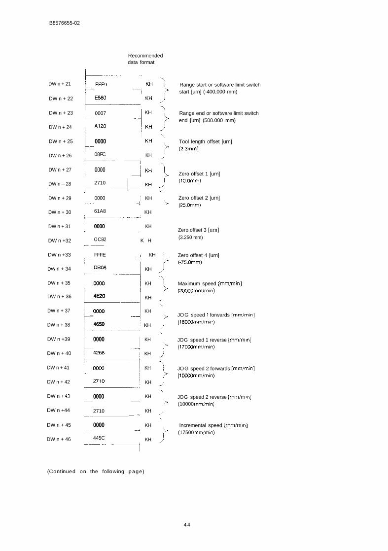
B8576655-02
Recommendeddata format
DW n + 21
DW n + 22
DW n + 23
DW n i- 24
DW n + 25
DW n + 26
DW n + 27
DW n + 28
DW n + 29
DW n + 30
DW n + 31
DW n +32
DW n +33
DW n + 34
DW n + 35
DW n + 36
DW n + 37
DW n + 38
DW n +39
DW n + 40
DW n + 41
DW n + 42
DW n + 43
DW n +44
DW n + 45
DW n + 46
k +u ‘HL0007 ~ KH
~0000 I KH
+
08FC KH—------ I
I I
L0000 J
~------ I ::2710
0000 ~ KH. . . . --1
-J>,
/’\
61A8 ~ KH
0000 KH—.— . .
OCB2 K H.—..————
FFFE ; KH ;‘-–— .-. i>
DB08 KH /)
14
>0000 KH
4E20 KH /}
>0000 KH
—
4650 ~ KH t—.’
I 0000 I
I 0000r J
12710
f..- — ~
0000~.—- —+I 445C
KH
KH
KH
KH
KH
KH
KH
KH
I‘;>(
‘,>
/’-.
Range start or software limit switchstart [urn] (-400,000 mm)
Range end or software limit switchend [urn] (500.000 mm)
Tool length offset [urn](2.3mm)
Zero offset 1 [urn](10.Omm)
Zero offset 2 [urn](25.Omm)
Zero offset 3 [urn](3.250 mm)
Zero offset 4 [urn](-75.Omm)
Maximum speed [mm/min](20000mm/min)
JOG speed 1 forwards [mm/min](18000mm/min)
JOG speed 1 reverse [mm/min](17000mm/min)
JOG speed 2 forwards [mm/min](10000mm/min)
JOG speed 2 reverse [mm/min](10000 mm/min)
Incremental speed [mm/mIn](17500 mm/min)
*.—— --- -’-””-~
(Continued on the following page)
4 4
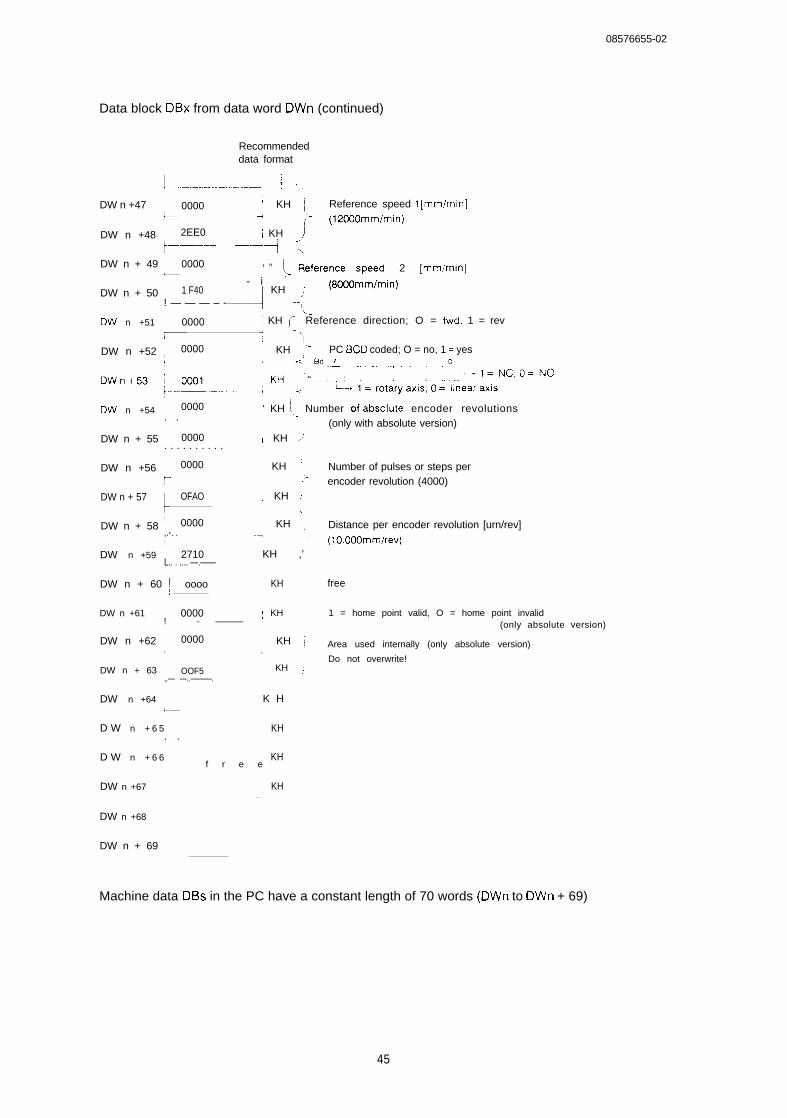
08576655-02
Data block DBx from data word DWn (continued)
Recommendeddata format
l ----------------------- .1 ...,
DW n +47 0000 ! KH ~ Reference speed 1 [mm/min]:.—. .+ ‘- (12000mm/min)j
DW n +48 I 2EE0 ~ KH J~-–—---- —--—j ‘->
DW n + 49 ~ 0000 ‘ H ~> Reference speed 2 [mm/min]L- i
DW n + 50 I 1 F40-----4
KH j (8000mm/min)
! — — — – - --1
LDW n +51 i 0000
I 4
1 KH ,f Reference direction; O = fwd. 1 = rev—— - .
)DW n +52 ! 0000 ~ KH ~> PC BCD coded; O = no, 1 = yes
DVV n +54 ~ 0000 ‘ KH I Number ofabsolute encoder revolutions. . (only with absolute version)
DW n + 55 ~ 0000 I KH /. . . . . . . . . .
DW n +56 ~ • 0000 KH : Number of pulses or steps per~.. /> encoder revolution (4000)
DW n + 57I
OFAO ; KH )-.
IDW n + 58 ~•…• •…•Þ0000 ~ KH : Distance per encoder revolution [urn/rev]
,.-. . -iI
- (10000mm/rev)DW n +59 ~ 2710 KH ,’
L.. . .... —.——
DW n + 60 ~- oooo KH free
DW n +61 0000 : KH 1 = home point valid, O = home point invalid! .— - ——— ., (only absolute version)
DW n +62 ~ 0000 ; KH ~ Area used internally (only absolute version),. .
Do not overwrite!DW n + 63 ~ OOF5 ; KH ,1
,.— —..———.
DW n +64 ~ K Hl–—
D W n + 6 5 KH. .
D W n + 6 6f r e e
KH
DW n +67 KH—,
DW n +68
DW n + 69 ~
Machine data DBs in the PC have a constant length of 70 words (DWn to DWn + 69)
45
08576655-02
Parameters requiring two words, e.g. backlash compensation, are 32-bit fixed point nutmbers. Ne-gative values are stored as 32-bit fixed point numbers in 2’s complement. When the value is inputor interpreted, remember that the programmer does not make any suitable format available forthis.
The machine data can only be transferred, read or deleted via the axis interface (parameterSSNR).
3.8.2 Structure of a Machining Program DB in the PC Memory
BA = 2 2 machining programs transferred from PC to IP246,6A = 23 machining programs deleted on the IP246,6A = 69 machining programs read from the IP246.
The structure and syntax of machining programs is explained in “Fundamentals of Positioning,Reference Manual”, Section 5 “Machining Programs and their Structure”.
46
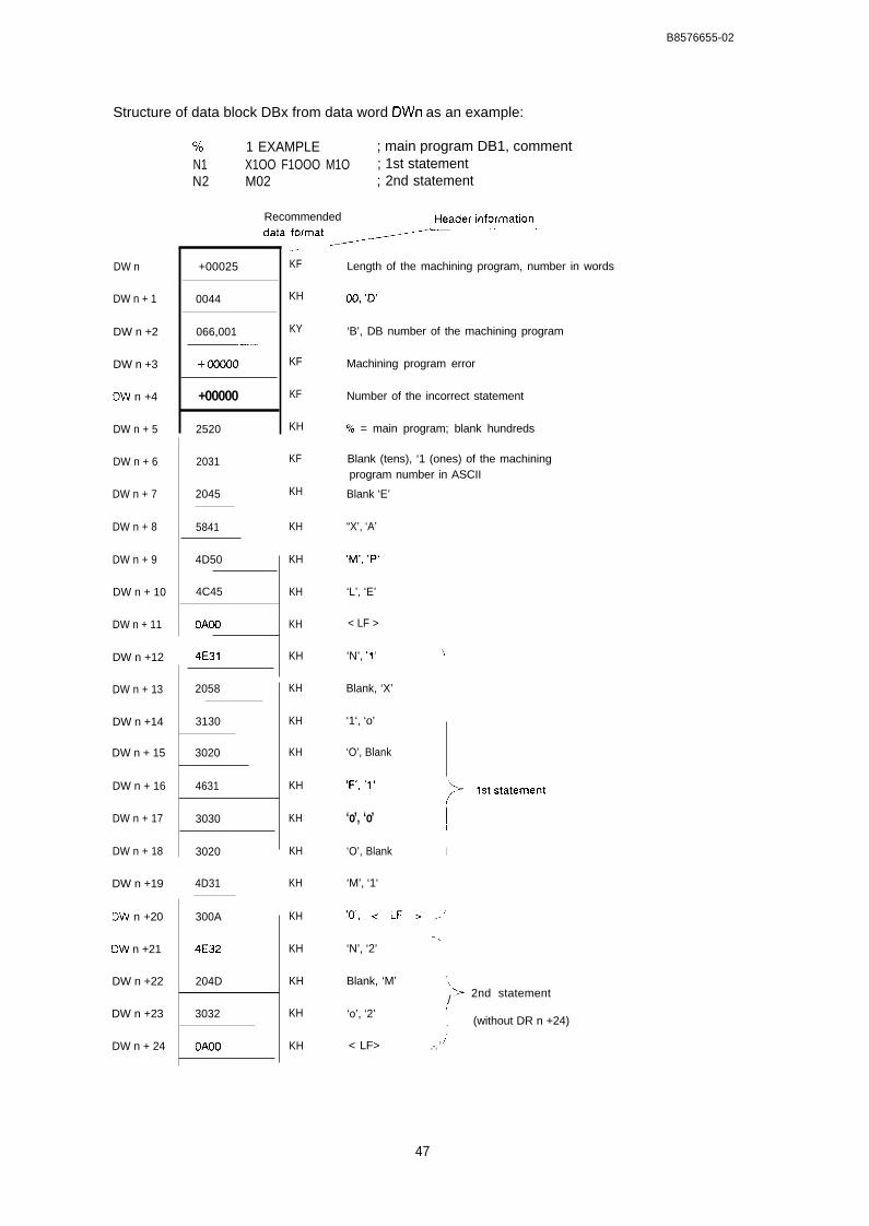
B8576655-02
Structure of data block DBx from data word DWn as an example:
DW n
DW n + 1
DW n +2
DW n +3
DW n +4
DW n + 5
DW n + 6
DW n + 7
DW n + 8
DW n + 9
DW n + 10
DW n + 11
DW n +12
DW n + 13
DW n +14
DW n + 15
DW n + 16
DW n + 17
DW n + 18
DW n +19
DW n +20
OW n +21
DW n +22
DW n +23
DW n + 24
0/0 1 EXAMPLE ; main program DB1, commentN1 X1OO F1OOO M1O ; 1st statementN2 M02 ; 2nd statement
Recommended IHeaderinfwnaticm
‘a’’ forma’ ~~ --------–—-
+00025
0044
066,001——
+00000
+00000
2520
2031
2045
5841
4D50
4C45
OAOO
4E31
2058
3130
3020
4631
3030
3020
4D31
300A
4E32
204D
3032
OAOO
.—— -KF
KH
KY
KF
KF
KH
KF
KH
KH
KH
KH
KH
KH
KH
KH
KH
KH
KH
KH
KH
KH
KH
KH
KH
KH
Length of the machining program, number in words
00, ‘D’
‘B’, DB number of the machining program
Machining program error
Number of the incorrect statement
% = main program; blank hundreds
Blank (tens), ‘1 (ones) of the machiningprogram number in ASCII
Blank ‘E’
“X’, ‘A’
‘M’, ‘P’
‘L’, ‘E’
< LF >
‘N’, ‘1‘‘i,
Blank, ‘X’
‘1‘, ‘o’
‘O’, Blank
,F:, ,1,‘~ lststatement[
‘o’, ‘o’ ~
‘O’, Blank I
‘M’, ‘1‘
‘(j’, < LF > ..-;
-.‘N’, ‘2’
Blank, ‘M’ t‘~ 2nd statement/
‘o’, ‘2’1
(without DR n +24)
< LF> ~.-. ’
47
B8576655-02
The length of the machining program depends on the number of programmed statements. Themachining program DB can have a maximum length of 512 words.
If a machining program DB is generated or modified in the PC, the length in words must beupdated in DWn. The length of the machining program is the area from data word DWn up toand including the data word in which < LF > follows M02 (DWn + y).
Machining programs are not restricted to a specific axis. They can be transferred, read anddeleted via any interface of the IP246 (parameter SSNR - axis 1 or axis 2).
3.8.3 Structure of the SYSID of the IP246 in the PC Memory
The system identification SYSID (module identifier) can be
transferred in part to the IP246 with BA = 24and
read completely from the IP246 with BA = 70.
The structure of the system identification for the IP246 is described in “Functions, ReferenceManual”, Section 3.19 “SYSID Input”.
3.8.3.1 Read SYSID (BA = 70)
The system identification SYSID stored in data block DBx from data word DWn taking theexample of an absolute version of the IP246. The system identification occupies nine wordswhen read from the IP246.
Recommended
DW n
DW n + 1
DW n + 2
DW n +3
DW n + 4
DW n + 5
13W n +6
DW n + 7
DW n + 8
data format
E:
p,:‘AO’
I ‘1’ 1 KS+—
1 ‘1’J
KS
*—-”–—I 000,000 I(Y
I 000,000 KY
000,000 KY
t
Module versionhere IP246 absolute version
)-.
(> Firmware release{ here AO1.1I
/“
DRn +6: module number
DRn +7: slot number
DRn +8: page number
48
B8576655-02
3.8.3.2 SYSID Input (BA = 24)
The system identification SYSID is stored in data block DBx from data word DWn. The systemidentification is limited to three data words when writing to the IP246.
Recommendeddata format
DW n
E-1
000,000~ KY DRn: module number [0...99]
DW n + 1 000,000 KY DR n + 1: slot number [0,.,255]
DW n + 2 000,000 KY DR n +2: page number[O,,.255]
If the same data block is used for reading the SYSID from the module and for writing the SYSIDto the module, then the value in the parameter QANF must be increased by six (writing to theIP246) compared with the value in the parameter ZANF (reading from the IP246).
3.8.4 Structure of the Machine Data Directory
The machine data directory can be read from the IP246 with
BA = 64
The machine data directory has a constant length of four data words. If the machine data recordis missing for an axis, the data words have the value zero.
The machine data directory in data block DBx from data word DWn has the following structure:
Recommendeddata format
DW n
i
~ 0 0 0 , 0 0 1 KY DB no, of the machine data record-—.—.
DW n + 1 ~ + 00070 KF Length in words-— . . . . . —.. .—....—..—+
Dw n + 2 ; 000,005 ,0’ DB no. of the machine data record-——— .....,
,- Axis 1
Ax Is 2
DW n + 3 \ + 00070 ; KF Length in wordsL——...-.. ....–.— . . . . .
49
B8576655-02
3.8.5 Structure of the Machining Program Directory
The machining program directory can be read from the IP246 with
BA = 65
The length of the directory is variable and depends on the number of machining programs on thepositioning module. A maximum of 256 machining programs can be stored on the IP246 (DBO toDB255). In the directory, two data words are required for each machining program. The directorycan therefore be a maximum of512 words long.
The entries in the directory are not sorted according to the DB number but are stored in theorder in which they are entered on the IP246.
if the data block (DBx) selected for entry of the machining programs is not long enough, the re-maining data are stored in the next data block (DBx + 1 ) from data word DWO.
A destination start address (parameter ZANF) can only be selected for DBx. Entries are madeonly up to data word DW255 in the data blocks DBx and DBx + 1.
If two DBs are required, data block DBx must be installed up to and including DW255. Otherwisethe program will be aborted with an error message.
The following rule applies to the length of data block DBx:
length = (possible entries* 2) + destination start address ZANF
for DBx + 1 the following applies:
length = remaining entries * 2.
A further switch to a data block DBx+2 is not possible. If the directory cannot be stored comple-tely in the PC memory, the job is aborted with an error message.
50
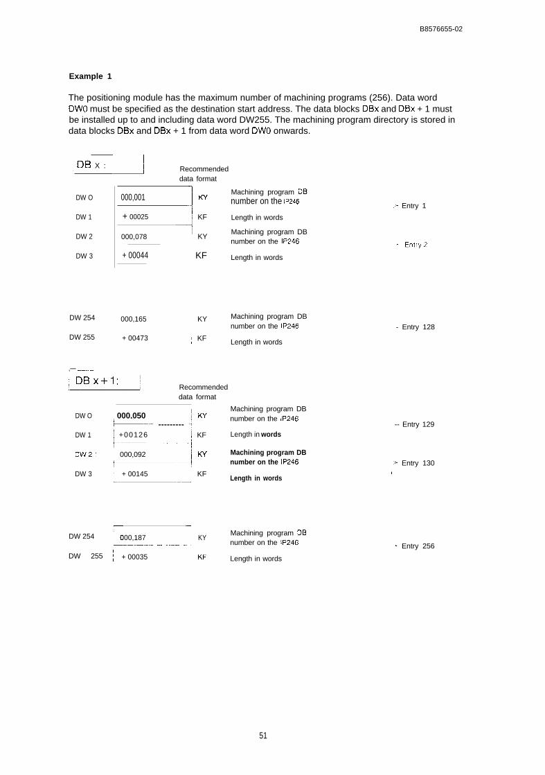
B8576655-02
Example 1
The positioning module has the maximum number of machining programs (256). Data wordDWO must be specified as the destination start address. The data blocks DBx and DBx + 1 mustbe installed up to and including data word DW255. The machining program directory is stored indata blocks DBx and DBx + 1 from data word DWO onwards.
~ DB X :L d Recommended
DW O
DW 1
DW 2
DW 3
DW 254
DW 255
,— ————...——
data format
000,001
I
w
+ 00025 1 KF
1000,078 ~ KY
+ 00044 ~ KF
000,165 ; KY
+ 00473 ; KF
Recommendeddata format
DW O ~ 000,050 I KYk---- --------- ;
DW 1 I +00126 ~ KF,-.-–––—–1
DW2 I 000,092 1 w~-–—”-”-:
DW 3I
+ 00145 I KF–-*
r “iDW 254 000,187 KY
+——-—.–.– - -.-–- - I
DW 255 ~ + 00035 ~ KF
Machining program DBnumber on the IP246 ~ Entry 1
Length in words
Machining program DBnumber on the IP246
Length in words
Machining program DBnumber on the IP246
Length in words
Machining program DBnumber on the IP246
Length in words
Machining program DBnumber on the IP246
Length in words
Machining program DBnumber on the IP246
Length in words
- Entry 128
-- Entry 129
~ Entry 130I
- Entry 256
51
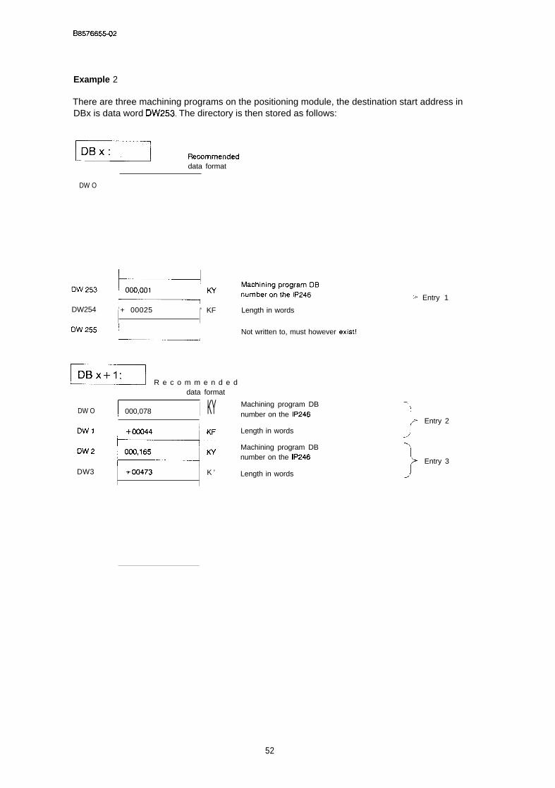
B8576655-02
Example 2
There are three machining programs on the positioning module, the destination start address inDBx is data word DW253. The directory is then stored as follows:
EEEcl R’=.....,,,data format
DW O
DW254 i + 00025 ‘ KF Length in words
‘W255 ~1 Not written to, must however exist!
_ R e c o m m e n d e ddata format
DW O 1 000,078 I KY
‘w’ UK’DW3 +00473 K ’
~ Entry 1
Machining program DB —.\
number on the IP246
JEntry 2
Length in words
Machining program DBnumber on the IP246
}
Entry 3
Length in words
52
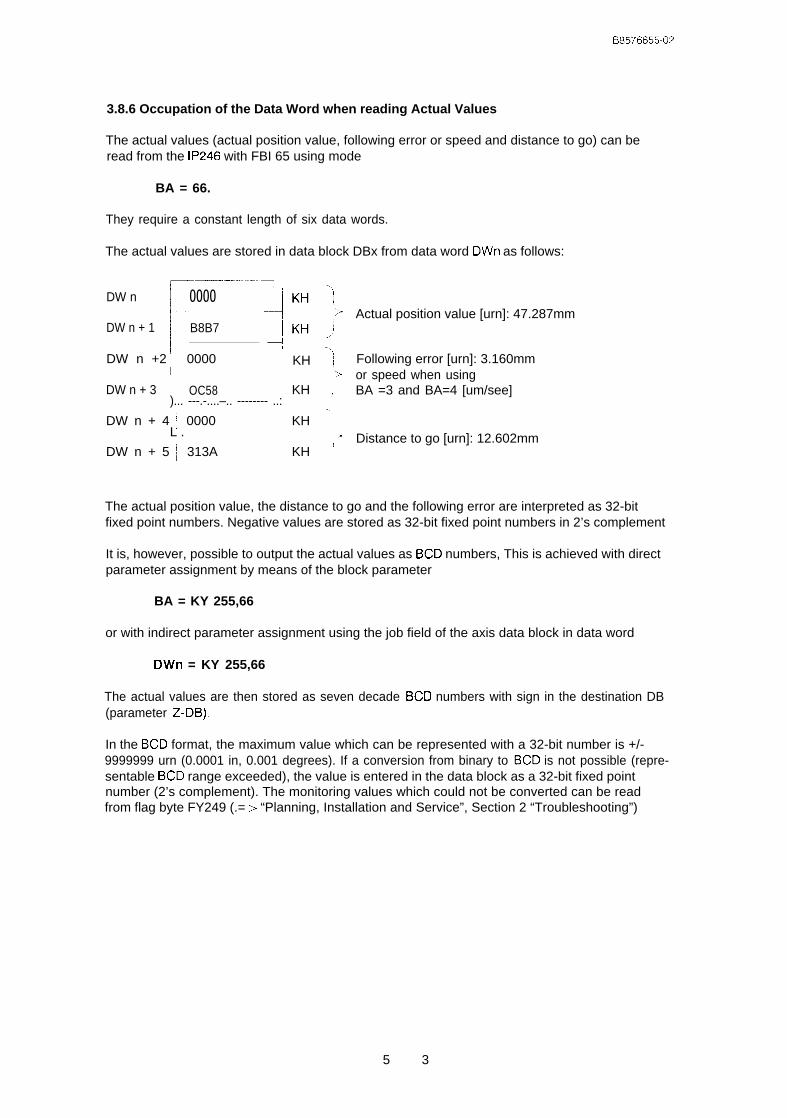
B8576655-02
3.8.6 Occupation of the Data Word when reading Actual Values
The actual values (actual position value, following error or speed and distance to go) can beread from the IP246 with FBI 65 using mode
BA = 66.
They require a constant length of six data words.
The actual values are stored in data block DBx from data word DWn as follows:
~-—.–-........““-1
DW n
E
0000.1
DW n + 1 B8B7 JI
DW n +2 ~ 0000[—
DW n + 3 OC58)... ---.-....–.. -------- ..:
DW n + 4 ~ 0000L .
DW n + 5 ~ 313A
-.,KH ~
‘;>KH j
KH ‘“,.
KH ‘
Actual position value [urn]: 47.287mm
Following error [urn]: 3.160mmor speed when usingBA =3 and BA=4 [um/see]
Distance to go [urn]: 12.602mm
The actual position value, the distance to go and the following error are interpreted as 32-bitfixed point numbers. Negative values are stored as 32-bit fixed point numbers in 2’s complement
It is, however, possible to output the actual values as BCD numbers, This is achieved with directparameter assignment by means of the block parameter
BA = KY 255,66
or with indirect parameter assignment using the job field of the axis data block in data word
DWn = KY 255,66
The actual values are then stored as seven decade BCD numbers with sign in the destination DB(parameter Z-DB).
In the BCD format, the maximum value which can be represented with a 32-bit number is +/-9999999 urn (0.0001 in, 0.001 degrees). If a conversion from binary to BCD is not possible (repre-sentable BCD range exceeded), the value is entered in the data block as a 32-bit fixed pointnumber (2’s complement). The monitoring values which could not be converted can be readfrom flag byte FY249 (.= > “Planning, Installation and Service”, Section 2 “Troubleshooting”)
5 3
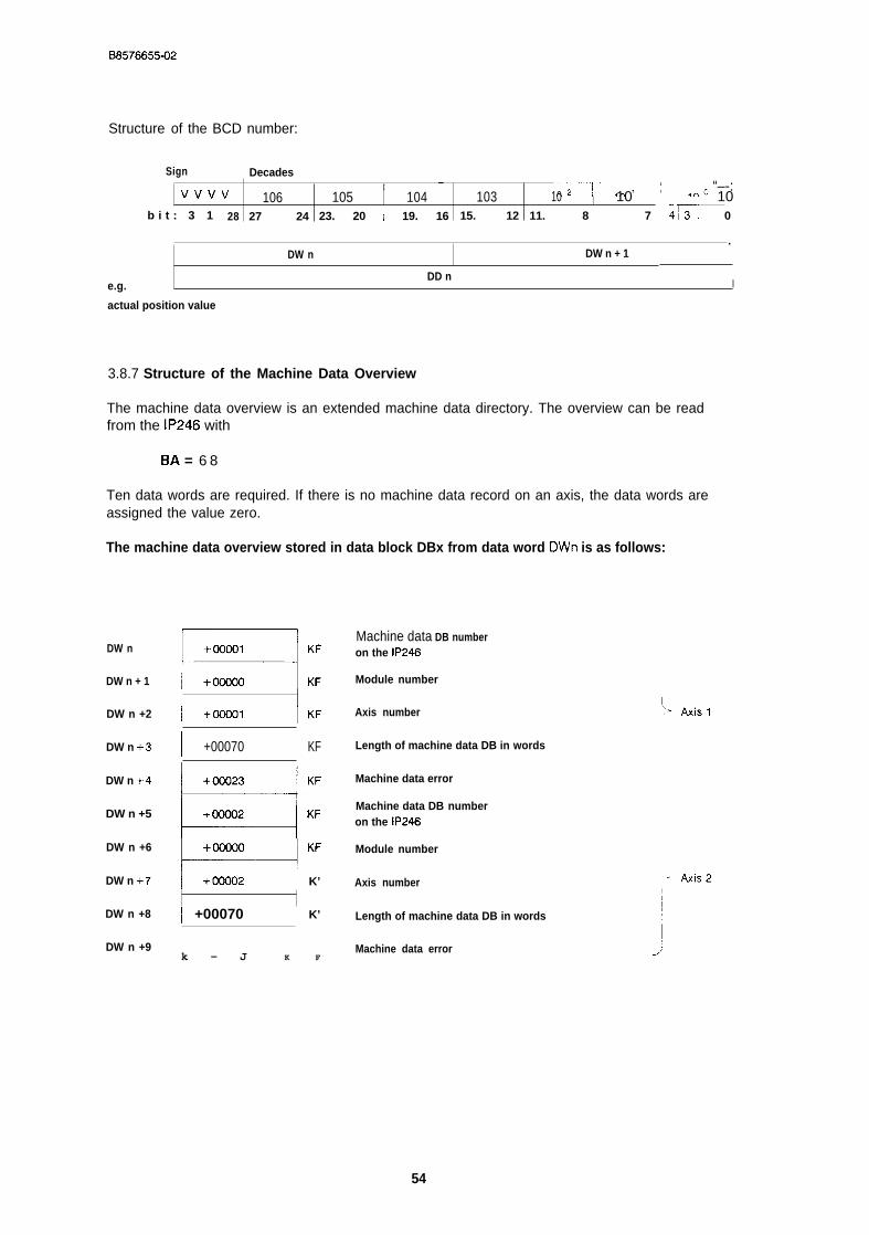
B8576655-02
Structure of the BCD number:
Sign I Decades —Vvvv I
106—2-;-—”:””””—--”;’ “–-:
105 104 103 10 I 10 10b i t : 3 1 28 27 24 23. 20 ~ 19. 16 15. 12 11. 8 ] 7 4~. 0
DW n.
DW n + 1 ~
e.g.DD n
I
actual position value
3.8.7 Structure of the Machine Data Overview
The machine data overview is an extended machine data directory. The overview can be readfrom the IP246 with
BA = 6 8
Ten data words are required. If there is no machine data record on an axis, the data words areassigned the value zero.
The machine data overview stored in data block DBx from data word DWn is as follows:
DW n
DW n + 1
DW n +2
DW n +3
DW n +-4
DW n +5
DW n +6
DW n +7’
DW n +8
DW n +9
I +Ooool \KF
Machine data DB numberon the IP246
Module number
Axis number
1 +00070 1 KF Length of machine data DB in words
WKFw ‘FW4“/ +OOQ02 I K’
Machine data error
Machine data DB numberon the IP246
Module number
Axis number
I +00070 I K’ Length of machine data DB in words
k - J K FMachine data error
54

0 8 5 7 6 6 5 5 - 0 2
3.9 Technical Data
S5-115U S5-135U S5-150U S5-155U .—~1 IBlock number 165 165 165
’ 6 5 -JBlock name PER:PDAT PER:PDAT I PER:PDAT PER:PDAT
Library number.-r--”’-;w;d,”-’
P71200-S5165-D-1 P71200-S9165-D-I P71200-S4165-D-I lP71200-S6165-D-1~
Call length 13 words 13 words ~ 13 words
Block length 646 words 533 words “-–~-:: :-::624 words ~
Nesting depth 1 1 - - - 1 ..- 1Secondary Integratedblocks handling blocks Handling blocks Handling blocks Handling blocks !
Occupation of - 15 data words from parameter DWNR of thedata area axis data block DBNR
- DB165 occupied from data word DWO to DW47- In indirect parameter assignment via DBx: data word DW1 and DW2
,Occupation of FY206 to FY255 FY218 to FY255
~–--”- - . . . - . - . . ,I FY200 t o FY255 1 FY200 t o FY255
flag area as scratchpad flag:i as scratchpad flag@ scratchpad flag$as scratchpad flags
Occupation in “-’-~–—..-+--------- . . . . . . . . . . . . . .
I
system data area none RS60 and RS61 I yes ~ yes
Systemstatements yes yes yes
Miscellaneous Interruptsblocked at timesin the FB bycommands IA/RA. An 1Acommand iscancelled bythis. L
Handling blocks Handling blocksFB120 SEND, FBI 80 SEND,FB121 RECEIVE FB181 RECEIVEFB122 FETCH FB182 FETCHnd FB125 nd FB185
SYNCHRON
1
SYNCHRONmust be loaded. ust be loaded.
~-—\ \Maximum I Dependent on the BAand the selected field,runtimes in ms
IICPU CPU CPU ‘CPU CPU CPU CPU941 942 943 944 922 928 92812
Write and 25.7 9.6 5.5 3.8 3.0 1.0 0.5delete jobs to , to to to to to toBA20 to BA24 32.4 17.4 13.6 9.1 13.0 6.6 6.3
1 \S5 cycles (min.) 12-6 ‘ 2-4
I1 +— ! 1 -++——
Read jobs 125.818.0 16.5 13.2 13.0 11.0 ~0.5BA64 iO BA70 to to to to to to ~ to
34.5 15,0 13.0 7.5 13.0 6.6 6.3
With BA66 max. 81.0 21.2 14.8 18.3( I I I I I
S5 cycles (min.) 2-4
direct parameter Iassignment / 2.2
i-1
I
J-1.3 1.7=
2-4
0.07
1Handling blocksFB120 SEND,FB121 RECEIVEFB122 FETCHnd FBI 25
SYNCHRON~ust be loaded.
,——..
ze (standar~ value = O)
II .7
r.-
2.00 to5.8 5.9
—-–+””Z-4 12-4—-–----- t---
LJi--------
=---+--1I
.-L—–_
55

B8576655-02
3.10 Notes on Starting Up the Positioning Module IP246 via the PCInterface
If you start up the positioning module via the PC interface, the system identification (SYSID) mustbe transferred to the module before the machine data are transferred. After power up, the follo-wing defaults apply:
module number = o,slot number = O and
- page number = o.
The machine data can then be transferred to the module, Only machine data with a modulenumber (DLn + 3 of the machine data DB) identical to the module number in the SYSID (DRn + 6or DRn) are permitted.
If the machine data are valid, the axis can be moved in the JOG mode or incremental relativemode. Absolute targets can only be approached with both the incremental and absolute versionafter calibration of the axis (mode 5).
There is no “overwrite mode” for machine data. If an axis requires new machine data, the follo-wing operations must be carried out:
delete the “old” machine data record on the axis (BA21 )
- transfer the “new” machine data record to the axis via the interface assigned to it (BA20).
A machine data record on the IP246 can be assigned any permitted DB number (DBo to DB255),There is, however, only ever one machine data record for an axis. The assignment of themachine data records to the axes is made using the axis number in the machine data record(DRn +3). The axes can therefore be assigned a machine data record with the same DB number,however, with a different axis number (= > “Functions, Reference Manual”, Section 3.17,1 “EnterMachine Data” or Section 3.17.2 “Delete Machine Data”). For more information about machinedata, refer to “Fundamentals of Positioning, Reference Manual”, Section 4 “Machine Data andtheir Structure”.
56
B 8 5 7 6 6 5 5 - 0 2
A maximum of 256 machining programs (DBO to DB255) can be stored on the positioningmodule. An existing machining program cannot be overwritten. If you wish to modify a machi-ning program stored on the IP246, then a certain procedure must be adhered to, just as with themachine data:
— output the machining program (machining program DB) from the IP246 to the PC memory,unless it already exists there (BA 69),
delete the machining program (machining program DB) on the IP246 (BA 23)
— transfer the modified machining program to the IP246 (BA 22).
A machining program is not restricted to an axis. Both axes can execute the same machiningprogram simultaneously. Machining programs can be transferred, read and deleted via any inter-face (axis) of a module. A machining program can, however, only be deleted when the other axisis not using this machining program ( = > “Functions, Reference Manual”, Section 3.18 “Execu-ting Machining Programs”). For more information about machining programs, refer to “Funda-mentals of Positioning, Reference Manual”, Section 5 “Machining Programs and their Structure”.
3.11 Using the Function Block
In cyclic operation it is not possible to address a module both with indirect and direct para-meter assignment.
Function block FB165 works with data block DB165. This must be installed up to and includingdata word DW47. A particular assignment of the data words is not necessary.
Data block DB165 is divided into two areas, in which data words DWI and DW2 are reserved forindirect assignment of parameters to the function block. Data words DW3 to DW47 are theworking area for FBI 65. You must not change the working area.
When assigning parameters to FB165, remember that the specified data blocks of the sourceand destination parameters must exist and must be adequately long.
The axis data block (parameter DBNR) must have the following length:
length = parameter DWNR + 14
The DB/DX number and the DW number can be selected as required.
57
B8576655-02
The data block is set up with a programmer, e.g. with the PG 685 STEP 5 under S5-DOS (stageIll) with the following commands (after exiting the presetting mask):
< FI > (input)< F1 > (block)P c (input device)DB160 (block) enter key < [ >
DW O: KY = 000,000DW 1: KY = 000,000DW 2: KY = 000,000DW 3: KY = 000,000
DW14: KY = 000,000 enter key < I >
FB165 can be called conditionally. The call must be made cyclically until the assigned mode iscompletely executed. The mode (job) runs
with direct parameter assignment as long as the parameter ANST has the signal state “1”,with indirect parameter assignment as long as data word DWn is not equal to KHOOOO inthe axis data block.
You must ensure that the parameter assignment is not overwritten while a mode is beingexecuted.
With indirect parameter assignment, the current data block must be open and supplied with theparameters DBNR (DW1) and DWNR (DW2) before the function block FB165 is called.
The positioning module IP246 does not service interrupts.
58
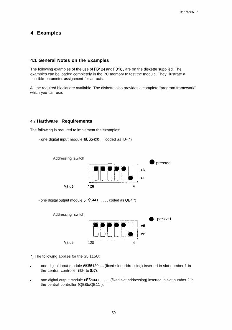
B8576655-02
4 Examples
4.1 General Notes on the Examples
The following examples of the use of FB164 and FB165 are on the diskette supplied. Theexamples can be loaded completely in the PC memory to test the module. They illustrate apossible parameter assignment for an axis.
All the required blocks are available. The diskette also provides a complete “program framework”which you can use.
4.2 Hardware Requirements
The following is required to implement the examples:
- one digital input module 6ES5420-.... coded as IB4 *)
Addressing switch
1 ● pressed,—–—.—— .
- one digital output module 6ES5441 . . . . . coded as QB4 *)
Addressing switch,.—L~[[~f~]:•‘ressed,,—.
—2
Value 128 4
*) The following applies for the S5 115U:
● one digital input module 6ES5420-,.., (fixed slot addressing) inserted in slot number 1 inthe central controller (IB4 to IB7).
● one digital output module 6ES5441 . . . . . (fixed slot addressing) inserted in slot number 2 inthe central controller (QB8toQB11 ).
59
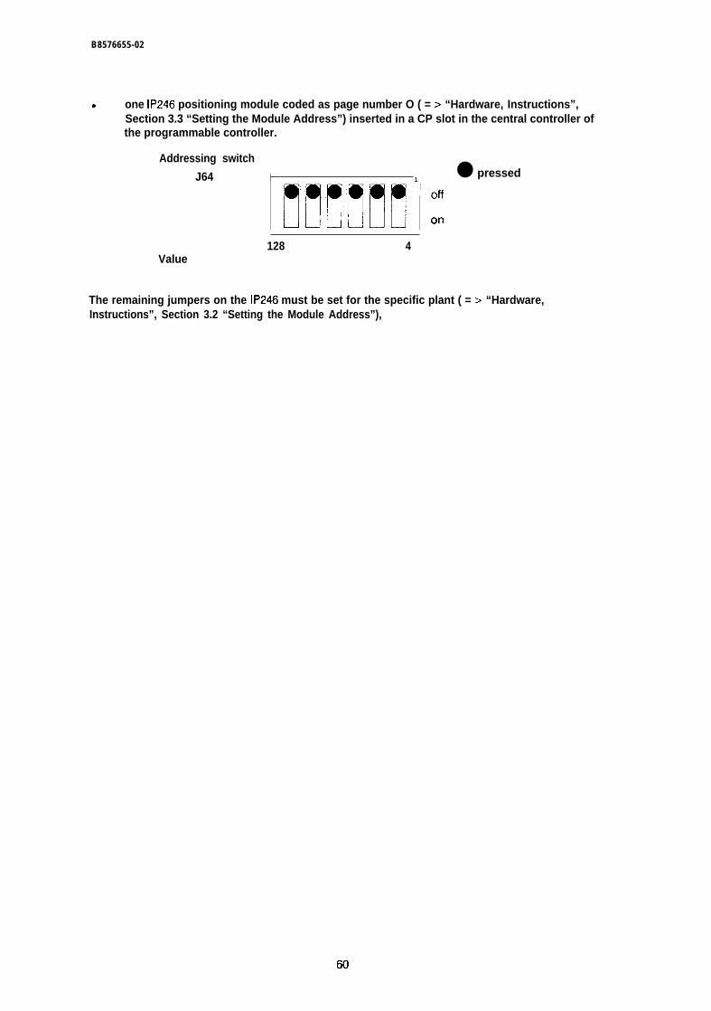
B8576655-02
9 one IP246 positioning module coded as page number O ( = > “Hardware, Instructions”,Section 3.3 “Setting the Module Address”) inserted in a CP slot in the central controller ofthe programmable controller.
Addressing switch
J64 I 1● pressed
mm ‘:128 4
Value
The remaining jumpers on the IP246 must be set for the specific plant ( = > “Hardware,Instructions”, Section 3.2 “Setting the Module Address”),
60
B8576655-02
4.3 Assignments for the Examples
4.3.1 Digital Inputs: (valid for all Programmable Controllers)
194 BA Mode with indirect parameter assignment in format KF
Mode with direct parameter assignment:
*** FBI 64 *** *** FBI 65 ***
I 4.0I 4.1I 4,2I 4.3I 4,4I 4.5I 4,6I 4.7
I 5,0I 5.1I 5.2I 5.3I 5,4I 5,5I 5.6I 5,7
I 6.0I 6,1I 6.2I 6.3I 6,4I 6,5I 6.6I 6.7
REFTIPP1TIPP2SMRIwSARWLLOE
STARSTOPVORWRUCKUEBNBCDINDI.AUFDIR. AUF
POS/PDATIN/Dl
RFEH
Reference/home pointJOG 1JOG 2Incremental relativeRead actual valueRead following errorRead distance to goClear cyclic monitoring
Read SYSIDRead machine data directoryRead actual valuesRead machine dataRead machine data overviewWrite SYSIDWrite machine dataDelete machine data
START commandSTOP commandFORWARDS commandREVERSE commandEnter data commandOutput in BCD codeIndirect param, ass. enter job FB165Direct param. ass. trigger job FB165
O = execute FB164 / 1 = execute FB1650)= indirect / 1 = direct parameter assignmentOverwrite DB with KHFFFF (FB191 and FB192/FB165)Clear retentive error
If none of the inputs I 4.0 to I 4.7 has signal state”1” in FB164, then the set mode is “followingerror” (mode 4) with direct parameter assignment.
4.3.2 Digital Outputs: (valid for S5-13511, S5-150U and S5-155U)
Q 4.0 PAFE Parameter assignment error FB164 and FB165Q 4.1 BFEH Module error FB164 and FB165Q 4.2 TBIT Active bit FBI 64Q 4.3Q 4.4Q 4.5Q 4.6Q 4.7
QB5 PAFE Image of the PAFE byte FY255, retentive
61
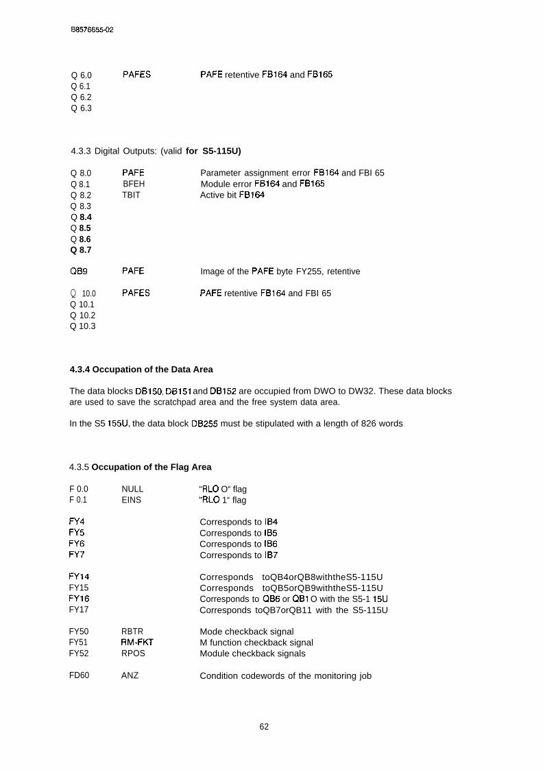
B8576655-02
Q 6.0 PAFESQ 6.1Q 6.2Q 6.3
PAFE retentive FB164 and FB165
4.3.3 Digital Outputs: (valid for S5-115U)
Q 8.0 PAFE Parameter assignment error FB164 and FBI 65Q 8.1 BFEH Module error FB164 and FB165Q 8.2 TBIT Active bit FB164Q 8.3Q 8.4Q 8.5Q 8.6Q 8.7
QB9 PAFE
Q 10.0 PAFESQ 10.1Q 10.2Q 10.3
Image of the PAFE byte FY255, retentive
PAFE retentive FB164 and FBI 65
4.3.4 Occupation of the Data Area
The data blocks DB150, DB151 and DB152 are occupied from DWO to DW32. These data blocksare used to save the scratchpad area and the free system data area.
In the S5 155U, the data block DB255 must be stipulated with a length of 826 words
4.3.5 Occupation of the Flag Area
F 0.0 NULL “RLO O“ flagF 0.1 EINS “RLO 1“ flag
FY4 Corresponds to IB4FY5 Corresponds to IB5FY6 Corresponds to IB6FY7 Corresponds to IB7
FY14 Corresponds toQB4orQB8withtheS5-115UFY15 Corresponds toQB5orQB9withtheS5-115UFY16 Corresponds to QB6 or QB1 O with the S5-1 15UFY17 Corresponds toQB7orQB11 with the S5-115U
FY50 RBTR Mode checkback signalFY51 RM-FKT M function checkback signalFY52 RPOS Module checkback signals
FD60 ANZ Condition codewords of the monitoring job
62
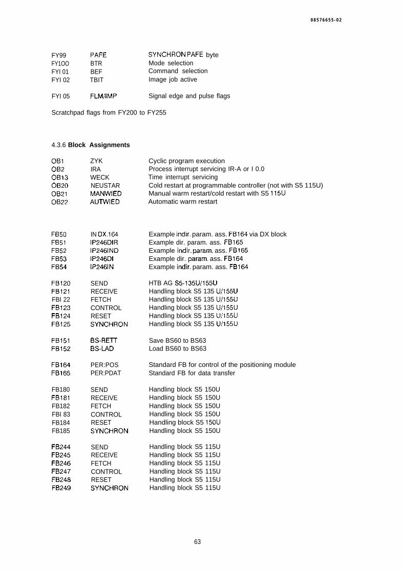
0 8 5 7 6 6 5 5 - 0 2
FY99 PAFE SYNCHRON PAFE byteFY1OO BTR Mode selectionFYI 01 BEF Command selectionFYI 02 TBIT Image job active
FYI 05 FLM/lMP Signal edge and pulse flags
Scratchpad flags from FY200 to FY255
4.3.6 Block Assignments
OB1OB2OB13OB20OB21OB22
FB50FB51FB52FB53FB54
FB120FB121FBI 22FB123FB124FB125
FB151FB152
FB164FB165
FB180FB181FB182FBI 83FB184FB185
FB244FB245FB246FB247FB248FB249
ZYKIRAWECKNEUSTARMANWIEDAUTWIED
IN DX.164IP246DIRIP2461NDIP246DIIP2461N
SENDRECEIVEFETCHCONTROLRESETSYNCHRON
BS-REITBS-IAD
PER:POSPER:PDAT
SENDRECEIVEFETCHCONTROLRESETSYNCHRON
SENDRECEIVEFETCHCONTROLRESETSYNCHRON
Cyclic program executionProcess interrupt servicing IR-A or I 0.0Time interrupt servicingCold restart at programmable controller (not with S5 115U)Manual warm restart/cold restart with S5 115UAutomatic warm restart
Example indir. param. ass. FB164 via DX blockExample dir. param. ass. FB165Example indir. param. ass. FB165Example dir. param. ass. FB164Example indir. param. ass. FB164
HTB AG S5-135U/155UHandling block S5 135 U/155UHandling block S5 135 U/155UHandling block S5 135 U/155UHandling block S5 135 U/155UHandling block S5 135 U/155U
Save BS60 to BS63Load BS60 to BS63
Standard FB for control of the positioning moduleStandard FB for data transfer
Handling block S5 150UHandling block S5 150UHandling block S5 150UHandling block S5 150UHandling block S5 150UHandling block S5 150U
Handling block S5 115UHandling block S5 115UHandling block S5 115UHandling block S5 115UHandling block S5 115UHandling block S5 115U
63
B8576655-02
DB104DB106DBI 07
DB150DB151DB152
DB160DB161DB164DB165DB166DB167
DB200DB201DB203DB204DB205DB206DB207
DXI 60DX161
SMDATSPRGSSYS-ID
RET 0B2RET OB13RET ANL
IP246AN1IP246AN2IP-FB164IP-FB165IP246AN3IP246AN4
LMDIRLPRGDIRLIWLMDATLMDATUBLPRGLSYS-ID
IP246AN3IP246AN4
Write machine dataWrite machining programWrite SYSID
Save flags 0B2Save flags OB13Save flags 0B21/0B22 (not required with S5 115U)
User DBUser DB (not used in example)Fixed working DB for FB164Fixed working DB for FB165User DB FB165, indirect parameter assignmentUser DB FB165, direct parameter assignment
Read machine data directoryRead machining program directoryRead actual valuesRead machine dataRead machine data overviewRead machining programRead SYSID
User DX (only with S5 135U and S5 155U)User DX (only with S5 135U and S5 155U)
64
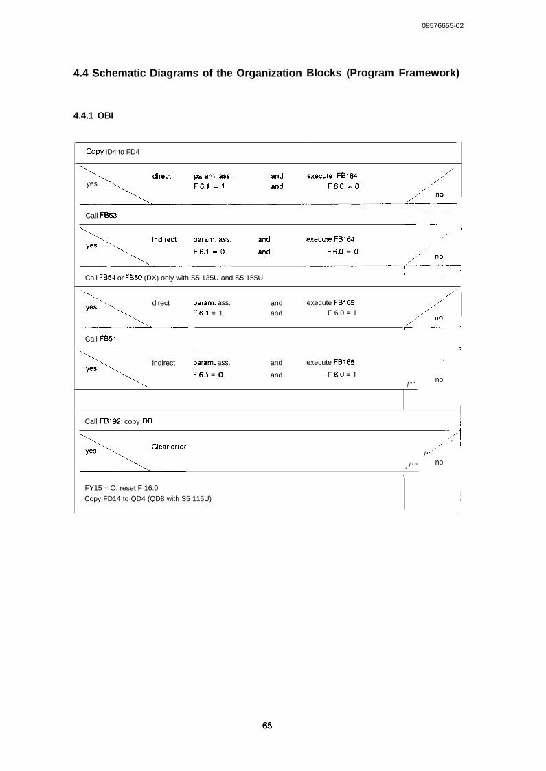
I
08576655-02
4.4 Schematic Diagrams of the Organization
4.4.1 OBI
Blocks (Program Framework)
COpy ID4 to FD4
yes
Call FB53
>:_’’’ms’s’ “ ‘ecu’’’’>:_:_.._Call FB54 or FB50 (DX) only with S5 135U and S5 155U
I —
\directyes
~
Call FB51
/
‘1
param. ass. and execute FB165F6.1 = 1 and F 6.0 = 1
,,/
<f----n:--]
4
\
indirect param. ass. and execute FB165yes
F6.1 = o and F 6.0 = 1
.,,,
no ~/ “ ’
Call FB192: copy DB I
-arefr”r
A/,,,,,. ’ !
./’/“
, / ’ ” no ~
I
FY15 = O, reset F 16.0
Copy FD14 to QD4 (QD8 with S5 115U)1I
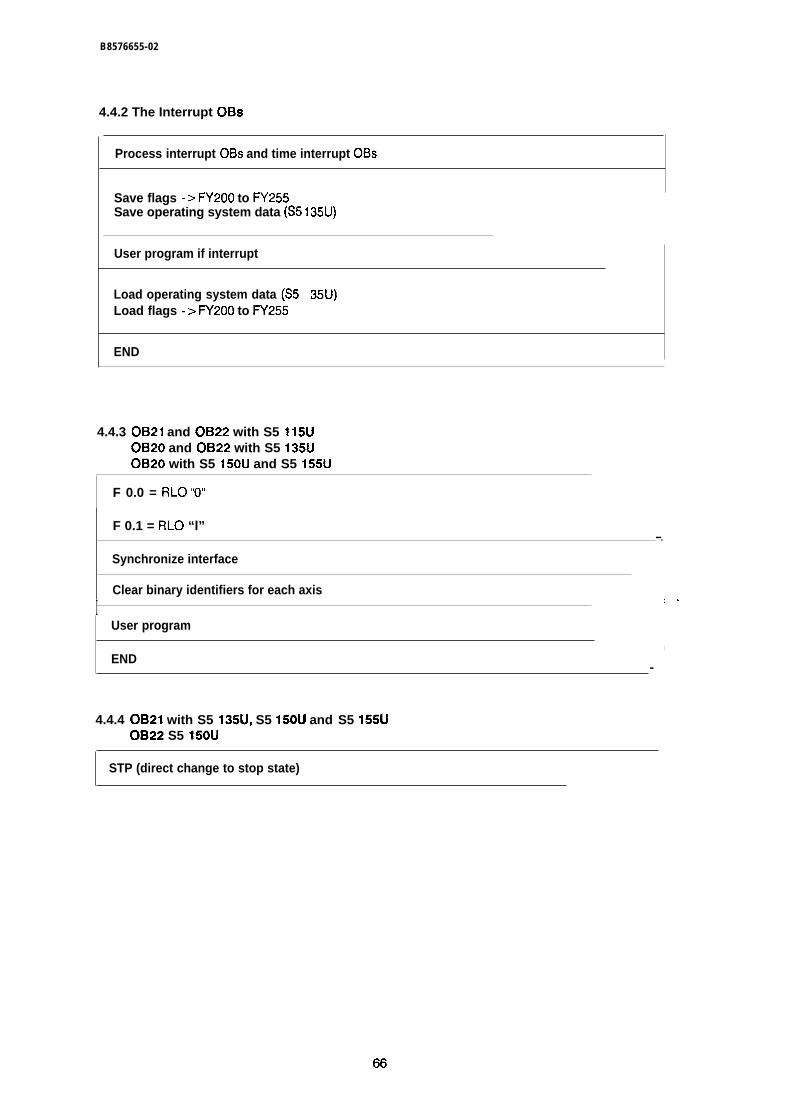
B8576655-02
4.4.2 The Interrupt OBS
Process interrupt OBS and time interrupt OBS
Save flags -> FY200 to FY255Save operating system data (S5 135U)
User program if interrupt
Load operating system data (S5Load flags -> FY200 to FY255
END
4.4.3 OB21 and OB22 with S5 115UOB20 and OB22 with S5 135UOB20 with S5 150U and S5 155U
F 0.0 = RLO “O”
F 0.1 = RLO “l”—.
Synchronize interface
Clear binary identifiers for each axis
I ,.User program
I
END-
4.4.4 OB21 with S5 135U, S5 150U and S5 155UOB22 S5 150U
STP (direct change to stop state)
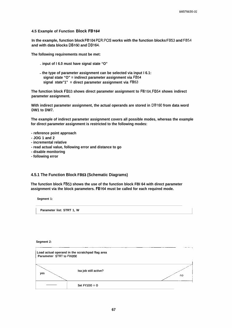
B8576655-02
4.5 Example of Function Block FB164
In the example, function block FB164 PER:POS works with the function blocks FB53 and FB54and with data blocks DB160 and DB164.
The following requirements must be met:
- input of I 6.0 must have signal state “O”
- the type of parameter assignment can be selected via input I 6.1:signal state “O” = indirect parameter assignment via FB54signal state”1” = direct parameter assignment via FB53
The function block FB53 shows direct parameter assignment to FB164, FB54 shows indirectparameter assignment.
With indirect parameter assignment, the actual operands are stored in I)B160 from data wordDW1 to DW7.
The example of indirect parameter assignment covers all possible modes, whereas the examplefor direct parameter assignment is restricted to the following modes:
- reference point approach- JOG 1 and 2- incremental relative- read actual value, following error and distance to go- disable monitoring- following error
4.5.1 The Function Block FB53 (Schematic Diagrams)
The function block FB53 shows the use of the function block FBI 64 with direct parameterassignment via the block parameters. FB164 must be called for each required mode.
Segment 1:
Parameter list: STRT 1, W
Segment 2:
I
I Load actual operand in the scratchpad flag areaI Parameter STRTtoi%V200
1
Isa job still active? ,,/’’”””yes ~
~ xI
Set FY1OO = O
67
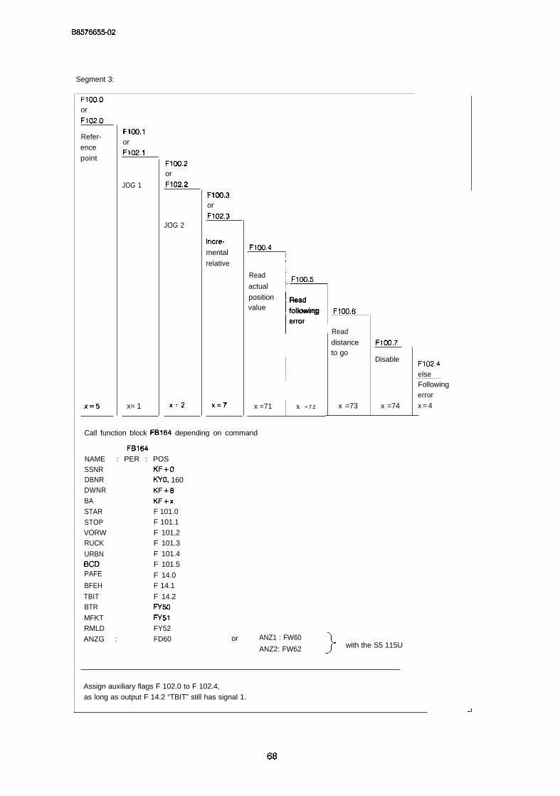
B8576655-02
Segment 3:
F1OO,Oor
F102.O
Refer-encepoint
X=5
F1OO.1orF102.1
JOG 1
x= 1
F1oo.2or
F102.2
JOG 2
)(=2
F1OO.3or
F102.3
incre-
mental
relative
)(=7
F1OO.4I
IRead
r
F1oO,5actual
position Readvalue following
error
II
x =71 X = 7 2
F1OO,6
Read
distanceto go
x =73
F1OO,7
Disable
x =74
Call function block FB164 depending on command
NAMESSNRDBNRDWNRBASTARSTOPVORWRUCK
URBNBCDPAFE
BFEH
TBITBTR
MFKTRMLD
FB164: PER : POS
KF+oKYo, 160KF+8KF+xF 101.0F 101.1F 101,2F 101.3F 101.4F 101.5
F 14.0F 14.1
F 14.2FY50
FY51FY52
ANZG : FD60 or ANZ1 : FW60
ANZ2: FW62 }with the S5 115U
F102.4elseFollowingerrorx = 4
Assign auxiliary flags F 102.0 to F 102.4,as long as output F 14.2 “TBIT” still has signal 1.
68

B8576655-02
Segment 4:
,..
\Parameter PAFE 0-> 1 edge ? (w 105) . . .
yes,.. /,.. .:.:-”: .“O
Set PAFE retentive F 16.0
Store PAFE byte (FY255) in FY15
Segment 5:
——..————-—-BE
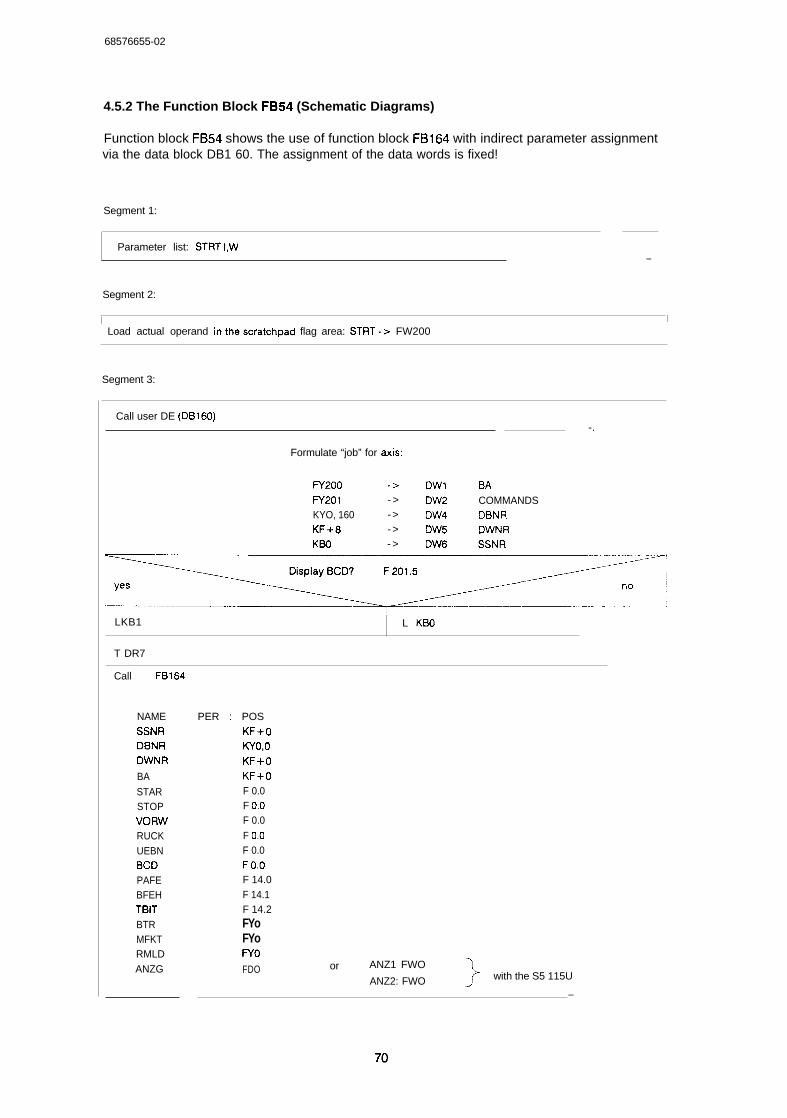
68576655-02
4.5.2 The Function Block FB54 (Schematic Diagrams)
Function block FB54 shows the use of function block FB164 with indirect parameter assignmentvia the data block DB1 60. The assignment of the data words is fixed!
Segment 1:
Parameter list: STRT I,W—
Segment 2:
I I/ Load actual operand inthescratchpad flag area: STRT-> FW200
Segment 3:
Call user DE (DB160)-.
Formulate “job” for axIs:
f7200 -> DW1 6/4FY201 - > DW2 COMMANDSKYO, 160 -> DW4 DBNRKF+8 -> DW5 DWNRKBO - > DW6 SSNR
/...==-Display BCD? F 201.5 I
yes
~~~” ~LKB1 L KBO
T DR7
Call FB164
NAMESSNRDBNRDWNR
BA
STARSTOPVORWRUCKUEBNBCDPAFEBFEHTBITBTRMFKTRMLDANZG
PER : POSKF+oKYo,oKF+oKF+OF 0.0F 0.0F 0.0
F 0.0F 0.0FO.OF 14.0F 14.1F 14.2FYoFYoWoFDO or ANZ1 FWO
ANZ2: FWO }with the S5 115U
—
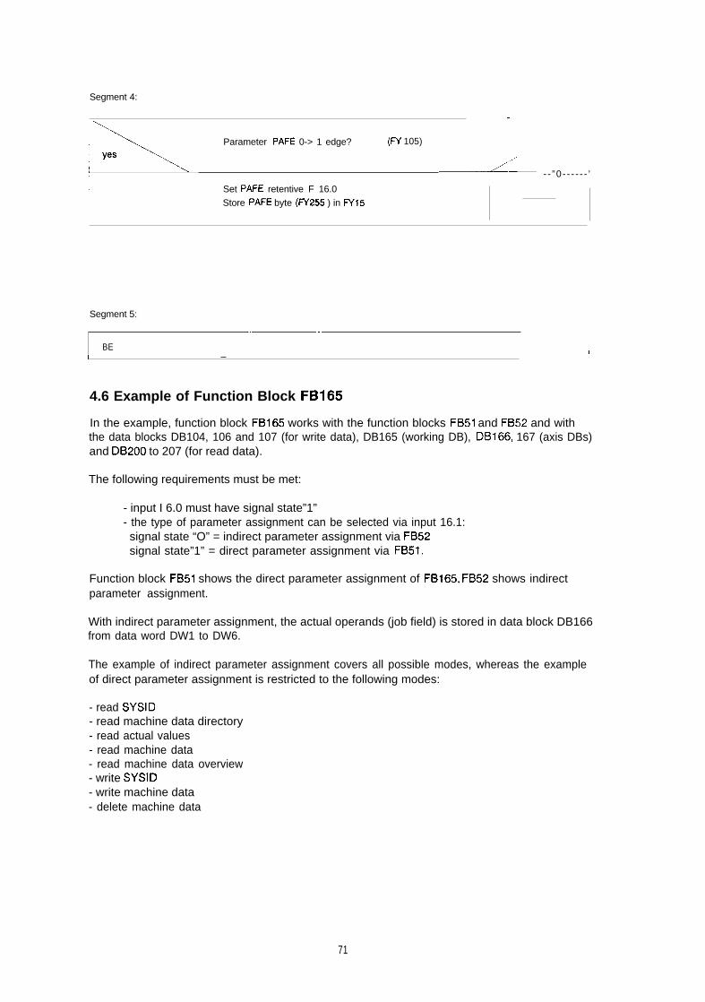
Segment 4:
.
P Parameter PAFE 0-> 1 edge? (w 105)yes
---+~ --”0- - - - - - ’
Set PAFE retentive F 16.0
Store PAFE byte (FY255 ) in FY15
Segment 5:
— —
BE II —
4.6 Example of Function Block FB165
In the example, function block FB165 works with the function blocks FB51 and FB52 and withthe data blocks DB104, 106 and 107 (for write data), DB165 (working DB), DB166, 167 (axis DBs)and DB200 to 207 (for read data).
The following requirements must be met:
- input I 6.0 must have signal state”1”- the type of parameter assignment can be selected via input 16.1:signal state “O” = indirect parameter assignment via FB52signal state”1” = direct parameter assignment via FB51.
Function block FB51 shows the direct parameter assignment of FB165, FB52 shows indirectparameter assignment.
With indirect parameter assignment, the actual operands (job field) is stored in data block DB166from data word DW1 to DW6.
The example of indirect parameter assignment covers all possible modes, whereas the exampleof direct parameter assignment is restricted to the following modes:
- read SYSID- read machine data directory- read actual values- read machine data- read machine data overview- write SYSID- write machine data- delete machine data
71

B8578855-02
4.6.1 Overview of the Relationship between the Mode and the Data Blocks in theRAM of the CPU and the Positioning Module
Machine data and machining programs are stored on the positioning module as data blocks.
The absolute DB and DW numbers refer to the example.
4.6.1.1 Writing Data to the IP246 and Deleting Data on the IP246
Modes BA: 20 to 24 ( = > “Functions, Reference Manual”)
PC RAM
DB165
Working DB
DB166Axis DB
Job field
Param. field:
Y
20Q-DB : KF+ 104QANF: KF+OZ-DB : KF+ 10
Y21Z-DB : KF+ 10
IQ-DB : KF+1136 2 2QANF: KF+OZ-DB : KF+ 111
23Z-DB : KF+ 111
!
DB104
-
DB106
n
DB107
-
B165
PER: PDAT
--l
IP246—.-RAM
~BI-o . j
E.---- Mach. data
i3Bl 11
c
Machiningprogram
I
SYSID
72
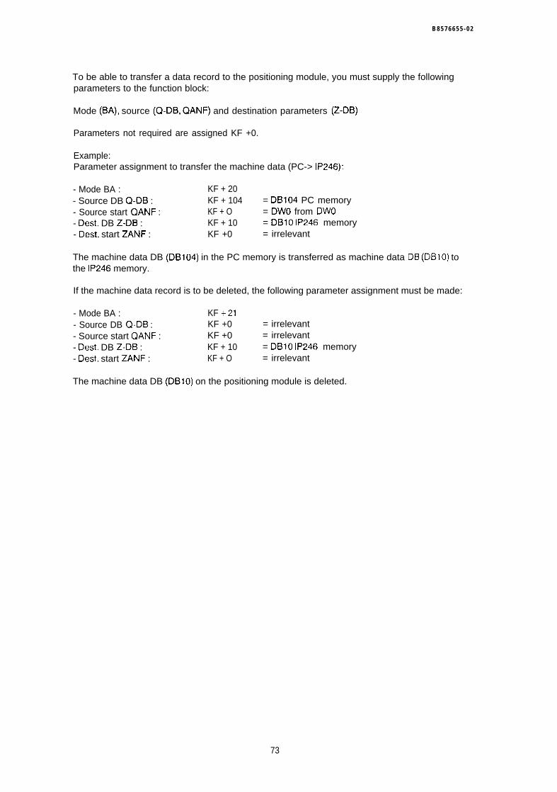
B 8 5 7 6 6 5 5 - 0 2
To be able to transfer a data record to the positioning module, you must supply the followingparameters to the function block:
Mode (BA), source (Q-DB, QANF) and destination parameters (Z-DB)
Parameters not required are assigned KF +0.
Example:Parameter assignment to transfer the machine data (PC-> IP246):
- Mode BA : KF + 20- Source DB Q-DB : KF + 104 = DB104 PC memory- Source start QANF : KF + O = DWO from DWO- Dest. DB Z-DB : KF + 10 = DB1O IP246 memory- Dest. start ZANF : KF +0 = irrelevant
The machine data DB (DB104) in the PC memory is transferred as machine data DB (DB1O) tothe IP246 memory.
If the machine data record is to be deleted, the following parameter assignment must be made:
- Mode BA : KF +21- Source DB Q-DB : KF +0 = irrelevant- Source start QANF : KF +0 = irrelevant- Dest. DB Z-DB : KF + 10 = DB1O IP246 memory- Dest. start ZANF : KF + O = irrelevant
The machine data DB (DB1O) on the positioning module is deleted.
73
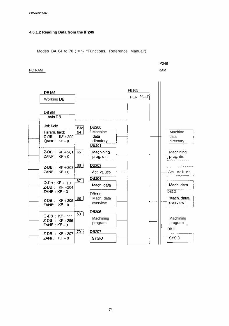
B8578855-02
4.6.1.2 Reading Data from the IP246
Modes BA 64 to 70 ( = > “Functions, Reference Manual”)
PC RAM
DB165FB165
Working DB IPER: PDAT~
J
1 IDB166 I
I / “isDB v------wI I I
Q-DB : KF+ 10 ~7JZ-DB : KF +204ZANF : KFi-O
Z-DB : KF+205 ~ZANF: KF+O
Q-DB : KF+lll ~Z-DB : KF+206ZANF : KF+O
Z-DB : KF+207 ~ZANF: KF+O
DB200/ Machine ~ i
k!z!!?+,DB203 ,
DB205Mach. dataoverview
DB206
Machiningprogram
DB207
SYSIDt
.
IP246
RAM
Machine jdata Idirectory .j
-] Machining
1..-. . . . . . . . .prog, dir.
~.. . . : - - - - - -
–.+ ACI, va lues !L.. ---.--––- -~~.-.
Mach. data ,-1.:
DB1O
+..........1
Mach. data. Iovetview
{ “-
Machiningprogram ~
DB11
E
74

08576655-02
To be able to read a data record from the positioning module, the following parameters must bespecified for the function block:
mode (BA), source (Q-DB) and destination parameters (Z-DB, ZANF)
Parameters not required are assigned KF+O.
Example:Parameter assignment to read machine data (I P246- > PC):
- Mode BA : KF +67- Source DB Q-DB : KF+ 10 = DB1O IP246 memory- Source start QANF : KF +0 = irrelevant- Dest. DB Z-DB : KF +204 = DB204 PC memory- Dest. start ZANF: KF +0 = DWO from DWO
The machine data DB (DB1O) on the positioning module IP246 is stored as machine data DB(DB204) from data word DWO in the PC memory.
4.6.2 The Function Block FB51 (Schematic Diagrams)
The function block FB51 shows the use of the function block FB165 with direct parameterassignment via the block parameters. FB165 must be called once for ail required modes.
DB167 from DWO to DW14 is used as the axis data block.
Segment 1:
Parameter list: STRT 1, W
Segment 2:
~
Load parameters in -> FW200
{
F 105.1 EDGSignal edge evaluation (rising) F 201.7
F 202.1 PUL
Segment 3:
Trigger byte = zero? (FY 100)
yes ,,/’” n., / ’ ”
‘ \
— —.
Trigger pulse job?/“”
yes no
FY200 --> FY1OO (PAR:ANST) BEC—
-1
.,
75
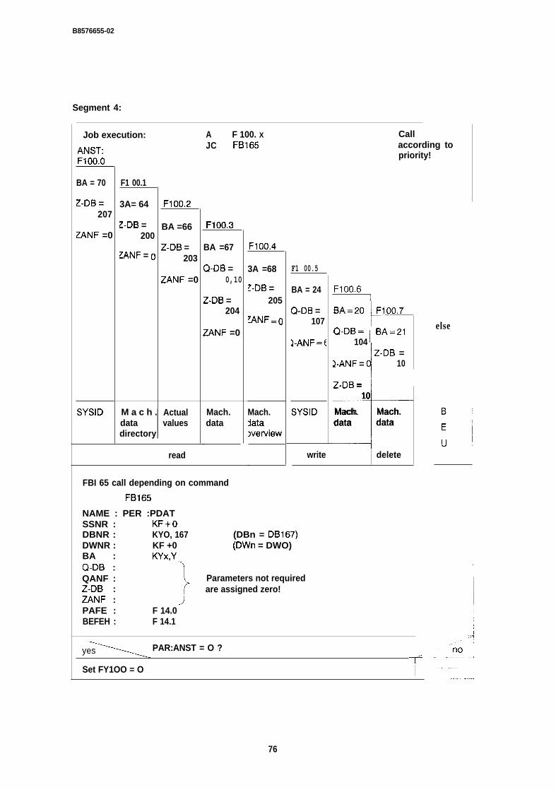
B8576655-02
Segment 4:
Job execution:
ANST:F1OO.O
BA = 70
Z-DB =207
ZANF =0
SYSID
F1 00.1
3A= 64
Z-DB =200
~ANF = (I
M a c h .datadirectory
F1OO.2
BA =66
Z-DB =203
ZANF =0
Actualvalues
read
A F 100. XJC FB165
F1OO.3
BA =67
Q-DB =0,10
Z-DB =204
ZANF =0
Mach.data
FBI 65 call depending on command
FB165
NAME : PER :PDATSSNR : KF+O
F1oo.4
3A =68
~.DB =205
~NF =o
Mach.~atawerview
F1 00.5
BA = 24
Q-DB =107
YANF =(
SYSID
Callaccording topriority!
F1OO.61
*BA=20 F1OO.7
Q-DB= 1 BA=21104
!
1 Z-DB =2-ANF = 10
*-
Z-DB =10
Mach. Mach.data data
DBNR : KYO, 167 (DBn = DB167)DWNR : KF +0 (DWn = DWO)BA : KYX,YQ-DB :QANF :
1
Parameters not requiredZ-DB : are assigned zero!ZANF :PAFE : F 14.0BEFEH : F 14.1
write delete
yes PAR:ANST = O ?~
Set FY1OO = O I
else
76
I
B8576655-02
Segment 5:
-ame’erp’’’edgeedge’ ,/:”””0 iSet PAFE retentive F 16.0
Store PAFE byte (IV255) in FY15
Segment 6:
I. ——.——.— —..-
BE— — .J
4.6.3 The Function Block FB52 (Schematic Diagrams)
The function block FB52 shows the use of the function block FBI 65 with indirect parameterassignment via data block DB1 66. The assignment of data words (DWn to DWn + 6) is fixed!
The pointer to the “job field” is entered in data block DB165. The data block number must bestored in data word DW1 and the data word number in data word DW2.
DB165 DW1 KY0,166 --> DB166 from DW1 to DW15DW2 KF + 1
Segment 1:
Parameter list: STRT 1, W,
Segment 2:
Load parameters in --> FW200
{
F 105.0 EDGEdge evaluation (rising) F 201.6
‘202.0 PUL!
77

B8576655-02
Segment 3:
C DB166 User DB for FB165,.. ’’”’”1,. ,.-
\
Coordination word > e Z e r o ? (DWn = DW1) /--”””-= F 202.1 (aux. f lag for condit ion call) ,=’
no yes
\Pulse “enter job” present?
yes\
\
Write or delete job, 20< = BA < =24?
/yes /.0
Assign calculated values: I Read job?
DWjob =! 64< = BA < = 70?k
b + (( BA-a)x4)where a =20 and b = 16 ~y!l-
BA --> FY200P
A --> 1%’200a --> IW203 a --> R’203b --> fW204 ~ b --> FY204
Calculate the address of the job fieldof the source/destination parameters
(DWn --> FY205)(DWn +2 --> IW206)
Formulate job: (DB166)
BA --> DW1 BADDn - -> DD2 Q-DB, QANFDDn +2 --> DD4 Z-DB, ZANF
Assign job: C DB165
KY0,166 --> DW1 ( D B n =DB166)KF+ 1 --> DW2 (DWn = DW1)
,/Z“no
/1 Assign job C DB165 I
/ IKY0,166 - - > DW1 (DBn-DB166)--> DW2 (DWn-DWl )
1
—
78
B8576655-02
Segment 4 :
—. —-——
Call DB165
\
Auxiliary flag for conditional call = “O”? (A F 202.1)yes
Call function block FB165
NAMESSNRDBNRDWNRBAQ-DBQANFZ-DBZANFPAFEBFEH
FB165
: PER : PDATKF +0KYo,oKF + OKYo,oKYo,oKF +0KYo,oKF +0F 14.0F 14.1
,,/”
/-’’’”/“
no
Segment 5:
F.
\Parameter PAFE O -> 1 edge? (FY165)
yes no,/--~—---
Segment 6:
. . . .I
BE

SIEMENS
SIMATIC S5IP246 Positioning Module Incremental
AbsolutePlanning, Installation and Service
6ES5246-4UA31 / -4UA416ES5246-4UBII / -4UB21
Installation Guide C79000-B8576-C656 -02
fM57665&02
Contents
1 Notes on Planning . . . . . . . . . . . . . . . . . . . . . . . . . . . . . . . . . . . . . . . . . . . . . . . . . . . . . . . . . . . . . . . . . . . . . . . . . . . . . . . . . . . . . . . . . . . . . . . . . . . . . . . . . . . . . . . . 31.1 Selecting the Drive . . . . . . . . . . . . . . . . . . . . . . . . . . . . . . . . . . . . . . . . . . . . . . . . . . . . . . . . . . . . . . . . . . . . . . . . . . . . . . ...........................................31.2 Mechanical Aspects . . . . . . . . . . . . . . . . . . . . . . . . . . . . . . . . . . . . . . . . . . . . . . . . . . . . . . . . . . . . . . . . . . . . . . . . . . . . . . . . . . . . . . . . . . . . . . . . . . . . . . .................31.3 The Position Encoder........., . . . . . . . . . . . . . . . . . . . . . . . . . . . . . . . . . . . . . . . . . . . . . . . . . . . . . . . . . . . . . . . . . . . . . . . . . . . . . . . . . . . . . . . . . . . . . . . . . ..........41.4 The Module . . . . . . . . . . . . . . . . . . . . . . . . . . . . . . . . . . . . . . . . . . . . . . . . . . . . . . . . . . . . . . . . . . . . . . . . . . . . . . . . . . . . . . . . . . . . . . . . . . . . . . . . . . . . . . . . . . . . . . . ..............41.6 Installation . . . . . . . . . . . . . . . . . . . . . . . . . . . . . . . . . . . . . . . . . . . . . . . . . . . . . . . . . . . . . . . . . . . . . . . . . . . . . . . . . . . . . . . . . . . . . . . . . . . . . . . . . . . . . . . . . . . . . . . . . . . .........111.6.1 Preliminary Remarks . . . . . . . . . . . . . . . . . . . . . . . . . . . . . . . . . . . . . . . . . . . . . . . . . . . . . . . . . . . . . . . . . . . . . . . . . . . . . . . . . . . . . . . . . . . . . . . . . . . . . . . . . . . . . . . . . 111.6.2 Module Test . . . . . . . . . . . . . . . . . . . . . . . . . . . . . . . . . . . . . . . . . . . . . . . . . . . . . . . . . . . . . . . . . . . . . . . . . . . . . . . . . . . . . . . . . . . . . . . . . . . . . . . . . . . . . . . . . . . . . . .........111.6.3 Wiring Check . . . . . . . . . . . . . . . . . . . . . . . . . . . . . . . . . . . . . . . . . . . . . . . . . . . . . . . . . . . . . . . . . . . . . . . . . . . . . . . . . . . . . . . . . . . . . . . . . . . . . . . . . . . . . . . . . . . . . . . . . . ... 13l.7Assigning Parameterstothe IP246 .....................................!....................................................... 141.8 Control of the lP246by the Programmable Controller . . . . . . . . . . . . . . . . . . . . . . . . . . . . . . . . . . . . . . . . . . . . . . . . . . . . . . . . . . . . . . . 18
2Troubleshooting -~~-~~-----~ti-~-~i-..~--~ -~~~~~------~~~-~~~-.~~ ...................192.1 Machine Data Errors and their Causes . . . . . . . . . . . . . . . . . . . . . . . . . . . . . . . . . . . . . . . . . . . . . . . . . . . . . . . . . . . . . . . . . . . . . . . . . . . . . . . . . . . . . . . 322.2 Module Errors and Possible Causes . . . . . . . . . . . . . . . . . . . . . . . . . . . . . . . . . . . . . . . . . . . . . . . . . . . . . . . . . . . . . . . . . . . . . . . . . . . . . . . . . . .........352.3 PGlnterface Errors . . . . . . . . . . . . . . . . . . . . . . . . . . . . . . . . . . . . . . . . . . . . . . . . . . . . . . . . . . . . . . . . . . . . . . . . . . . . . . . . . . . . . . . . . . . . . . . . . . . . . . . . . . . . . . . . . . ....38
3 Supplementary Notes . . . . . . . . . . . . . . . . . . . . . . . . . . . . . ... . . . . . . . . . . . . . . . . . . . . . . . . . . . . . . . . . ............................393.1 Keyboard Character Buffer . . . . . . . . . . . . . . . . . . . . . . . . . . . . . . . . . . . . . . . . . . . . . . . . . . . . . . . . . . . . . . . . . . . . . . . . . . . . . . . . . . . . . . . . . . . . . . . . . . . . . . . . . . 393.2 Multiprocessor Operation. . . . . . . . . . . . . . . . . . . . . . . . . . . . . . . . . . . . . . . . . . . . . . . . . . . . . . . . . . . . . . . . . . . . . . . . . . . . . . . . . . . . . . . . . . . . . . . . . . . . . . . . . . . . 39
3.3 Restarts . . . . . . . . . . . . . . . . . . . . . . . . . . . . . . . . . . . . . . . . . . . . . . . . . . . . . . . . . . . . . . ... . . . . . . . . . . . . . . . . . . . . . . . . . . . . . . . . . . . .................39
2
B6576656-02
1 Notes on PlanningThe following requirements must be met to allow problem-free use of the IP246:
● the drive has adequate power reserves
● there is no mechanical play in the control loop
● the machine data were compiled and optimized carefully
● the hardware installation is immune to HF interference. The installation guidelines wereadhered to in every respect.
1.1 Selecting the Drive
● The drive must have sufficient power reserves, i.e. it must never be operated at the powerlimit. The closed-loop control can otherwise no longer function correctly, since the rotaryspeed of the motor can no longer follow the rotary speed setpoint.
● The drive should be operated at a speed close to its rated speed to allow the resolution ofthe output voltage to be used to the full.
1.2 Mechanical Aspects
● Within the position control loop there must be no play. Otherwise, the drive tends to oscillateand all the advantages of closed-loop position control are lost.
● The position encoder should always be coupled directly to the motor shaft.
● The hardware limit switches connected to the IP246 must be arranged so that the axis canbrake from its maximum speed before the safety limit switches for the drive are reached.
3
B8578858-02
1.3 The Position Encoder
With the incremental version of the IP246, only encoders with two pulse trains displaced at90° from each other and having a zero marker can be used.
With the incremental version, it is advisable to use encoders with 5 V differential signals toimprove immunity to interference.
You must select the encoder resolution so that at low speeds there are still sufficient pulsesper time interval for evaluation. The minimum resolution should be greater than thepositioning accuracy by a factor of 10.
At vm~ the limit frequencies of the encoder and the module must not be exceeded.
1.4 The Module
When using the IP246, the machine data can be varied over a wide range. The limits of the en-tries must, however, not be exceeded. It is, for example, not possible to fall below the minimumspeed or exceed the maximum speed by including an override. By manipulating the machinedata, the actual maximum traversing speed may exceed 65000 m/min. Manipulating the machinedata in this way does, however, have consequences, e.g. for the selection of the position en-coder. For this reason, you should plan the machine data before buying and installing the com-ponents.
4
B6576656-02
1.5 Planning the Machine Data
The following data about the drive and the mechanical parts must be known when the machinedata are compiled.
Rated speed of the motorThis is the speed of the motor when there is a 10 V input signal at the power unit. It is not neces-sarily the same as the speed indicated on the rating plate. For safety reasons, the speed shouldbe taken from the commissioning report of the drive.
Speed of the motor at 10 V input signal
● ‘10”= C_= ‘rev’min]Maximum permitted deceleration of the driveThis value can be taken from the data sheets of the drive or from its commissioning report (seeequation 1, 2)
Maximum permitted deceleration
● b’””= r=Position encoder dataPulses (steps) per revolution
● z = 1Number of revolutions (with multi-turn absolute position encoders)
Axis dataif necessary, transmission ratio motor/axis
●❞✝
Distance travelled per axis revolution
Axis backlash
9 1=
[mm/sec2]
[pullrev]
[pul]
[mm]
[mm]
5
08576656-02
Hardware limit switchesWith linear axes, hardware limit switches should be fitted to the axis.
Type of limit switch
NC or NO
Coordinates (see eq, 7):
Hardware start limit switch
●
Hardware end limit switch
●
Machine data recordModule number
●
Axis
●
‘Hs= ~ ‘mm]
‘HE= ~ ‘mm]
o-99
1,2
Measuring system
9
Axis type
mm/inches/degrees
● linear/rotary I IMaximum deceleration
● 10....9999 mm/sec2b“”= r
1 [ m m / s e . ’ ]
Vm~ (Eq. 1)brna~ = -----.---..-
tmax
whereVmax = maximum speed (see eq. 8)tmax = maximum deceleration from Vmw to standstill
6
B8576656-02
bmax > bpe r m (eq. 2) I
af =
bf=
.= ‘mm’sec2]Acceleration forward
● 10...9999 mm/sec2
Deceleration forward
● 10...9999 mm/sec2
Acceleration reverse
● 10...9999 mm/sec2 ar =D-.-. . . . . . . . . . . . . . ‘mm’sec2]
Deceleration reverse
● 10...9999 mm/sec2~....
br = , “’-”””’-”--’l [mm/’e’21I —d
Vf (eq. 3)af = -“- bf = :!-
ta tb
Whereby:
]af, b, ar, br < bmax (eq. 4) I
vf = traversing speed forwardsta = acceleration time forwards
tb = deceleration forwards(reverse direction analogous)
Pulse evaluation (only with incremental version, use the highest possible value)
● 1,2,4 1=~.._.._i
Resolution factor (only with incremental version, is not evaluated in online operation withfirmware > A2.1)
● 0.1...99.9 R = ~ ‘“”’1000put]
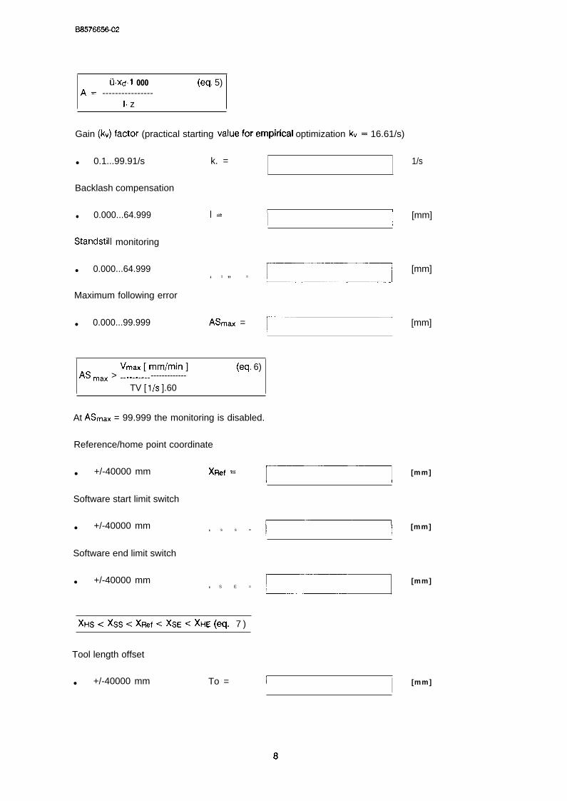
U.xdl 000 (eq. 5)A= ----------------
1. z
Gain (kv)factor (practical starting valueforempirical optimization k“= 16.61/s)
● 0.1...99.91/s k. =
Backlash compensation
● 0.000...64.999 1=
1/s
[mm]
Standstiii monitoring
● 0.000...64.999‘ t ” = c-o
Maximum following error
● 0.000...99.999 ASnlti =r 1
[mm]
[mm]
Vrn.x [ mm/min ] (eq. 6)AS Max > -.----_--- -------------
TV [ 1/s ].60
At ASm~x = 99.999 the monitoring is disabled.
Reference/home point coordinate
● +/-40000 mm“f= ~
Software start limit switch
● +/-40000 mm‘ s s = ~
Software end limit switch
● +/-40000 mm‘ S E = ~
)(Hs < XS,S -= XRef < %’ < XHE (eq. 7 )
Tool length offset
● +/-40000 mm To =
[mm]
[mm]
[mm]
I I [mm]
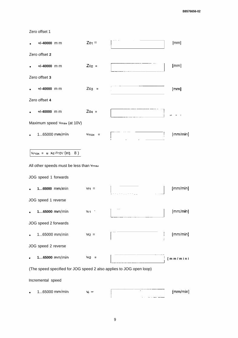
B8576656-02
Zero offset 1
● +/-40000 m m
Zero offset 2
● +/-40000 m m
Zero offset 3
● +/-40000 m m
Zol =
Z02 =
. . . . . . . . . .[mm]
Z03 = r ‘—‘] [mm]
Zero offset 4
● +/-40000 m m Z04 =—:--:--T ‘m m ]r.
Maximum speed Vmax (at 10V)
● 1...65000 mm/min Vmax =~-------------
-] [mm/min]L.-. . . I
Vmax = u Xd nlov ((?q. 8 )
All other speeds must be less than Vmax
JOG speed 1 forwards
● 1...65000 mm/min
JOG speed 1 reverse
● 1...65000 mm/min
Vfl =
Vrl =
rL – — . – — . . - — — _ _Q “nm’min]
~= ‘mm’m’n]JOG speed 2 forwards
● 1...65000 mm/min Vfz =L--..-:---------- ‘mm’m’n]
JOG speed 2 reverse
9 1...65000 mm/min Vr2 = ‘------- [ m m / m i n iL—~
(The speed specified for JOG speed 2 also applies to JOG open loop)
Incremental speed
● 1...65000 mm/min c—n ‘mm’min]
9
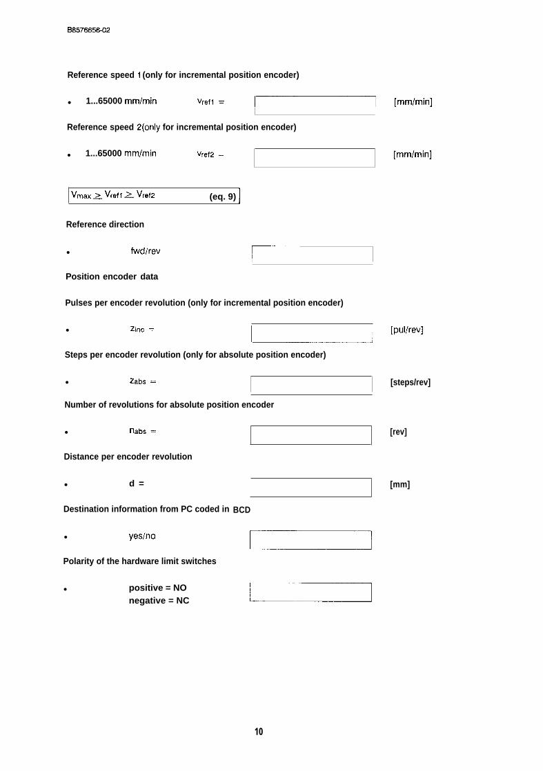
B6576656-02
Reference speed 1 (only for incremental position encoder)
● 1...65000 mm/min Vrefl = ~7
Reference speed 2(only for incremental position encoder)
● 1...65000 mm/min Vref2 =
Vmax > Vrefl 2 Vref2 (eq. 9) I
Reference direction
● fwdlrev~---—
1
Position encoder data
Pulses per encoder revolution (only for incremental position encoder)
● Zinc =
L.--1
Steps per encoder revolution (only for absolute position encoder)
● Zabs =
Number of revolutions for absolute position encoder
● tlabs =
Distance per encoder revolution
● d =
Destination information from PC coded in
● yeslno
Polarity of the hardware limit switches
● positive = NOnegative = NC
BCD
[mmlmin]
[mm/min]
[pullrev]
[steps/rev]
[rev]
[mm]
10
B8576656-02
1.6 Installation
1.6.1 Preliminary Remarks
● Plastic flooring and carpets and plastic or rubber soles can lead to static charges of up toseveral kV. Integrated circuits are sensitive to such high-voltage discharges. Never touchconductors and components without previously discharging your body to earth.
● Modules, power supply and encoder cables must only be removed or inserted when thecontroller is switched off. All external components, transmitters, drives, power electronicsetc. must be installed and optimized according to the manufacturers’ instructions. Thecomplete emergency stop circuitry must function according to the appropriate regulationsand the emergency stop limit switch must be installed, especially with linear axes.
1.6.2 Module Test
Visual test (see “Hardware, Instructions”, Section 3.1 ‘(Position of the Jumpers andSwitches”)
check the jumpers
eck the required page address
1 I ~~----””----’””~-------
1IL IdI
11
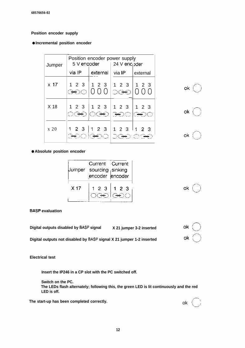
68576656-02
Position encoder supply
● Incremental position encoder
Jumper
x 17
X 18
x 20
Position encoder power supply5 V encjoder
1 2 3 1 2 3
C3+lo 000
1 2 3 1 2 3
O(IK) O(2+CI
I
24 V enc
via 1P
1 2 3
>Q@)—
1 2 3
36)0
1 2 3
>C9=0
● Absolute position encoder
)der
external
1 2 3
000
1 2 3
C?eo
mBASP evaluation
Digital outputs disabled by BASP signal X 21 jumper 3-2 inserted
Digital outputs not disabled by BASP signal X 21 jumper 1-2 inserted
Electrical test
Insert the IP246 in a CP slot with the PC switched off.
Switch on the PC.The LEDs flash alternately; following this, the green LED is lit continuously and the redLED is off.
The start-up has been completed correctly. ok o
12

B8576656-02
1.6.3 Wiring Check
Check the cable routing ok c)
- Check that control cables and power cables are separated and are notkinked. ok c1
- Check that the cables from and to the controller are shielded over their whole length,and are grounded on the controller side.
ok oThe laying and routing of ground lines is particularly important, since inadequate
cable cross sections in ground loops or when the ground is not connected can interfere with theoperation. The localization and elimination of such interference can take considerable time.
●
●
●
●
●
●
Make sure that the earth lines have an adequate cross section and are correctly routedand connected.
With 5 V position encoders, check that the inverse signal lines aretwisted pairs,
Check that the n~et and BS analog signal lines are twisted.
Check the following cables for short circuits, line breaks and correct pinassignment according to the hardware description.
Position encoder lines channel 1
Position encoder lines channel 2
Sefpoint line
Digital signal line
FUM signal wired?
24 V Sllpf)ty
Connect the cables when the power is switched off and screw them tight.
13
B6576656-02
1.7 Assigning Parameters to the IP246
Before you check the interaction between the IP246 and your drive, bring the drive into the per-mitted traversing range, i.e. between the hardware limit switches “start” and “end”. Make sure thatyou can reach the emergency stop switch at all times!
Switch the PC on.At this point in time you do not need a CPU program. If you have selected the setting“digital outputs blocked by BASP” on the IP246, the CPU must be in the “run” mode. TheCPU should not address the IP246 during the first phase of the start-up.
Switch the 24 V power supply on (the power unit remains switched off).
Establish the connection to the PG.
Start COM246 (online operation).
With all other actions you take, please note the error message line on the programmer. If a prob-lem occurs, you will obtain information about the type of problem.
Transfer the machine data and machining programs to the IP246.If an error message occurs, you must check and, if necessary, correct the machine dataaccording to the message received.
Testing the axes
Select the test mode for axis 1.
Start the “following errot’ mode (BA 4).Checkback signals:
Axis status: running ok c)
Closed loop controller: off ok ~
If an error message occurs you must eliminate the problem and start mode 4 again.
Switch on the power unit for axis 1.The axis must remain still and its drift must be hardly perceptible. If this is not the case,repeat the fine adjustment for O V.
Stop BA 4.Checkback signals:
ok ~
ok ~
Axis status: finished
Closed loop controller: on
14
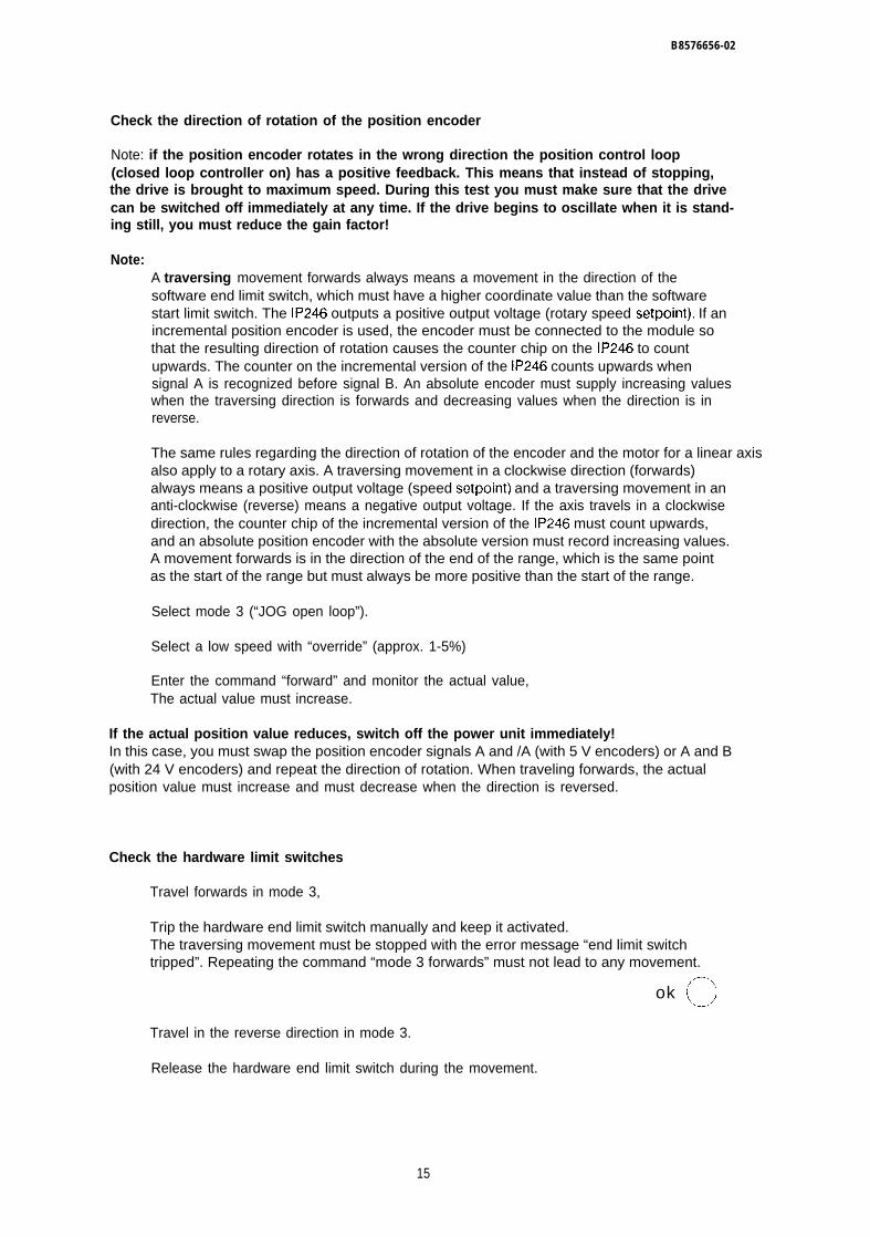
B8576656-02
Check the direction of rotation of the position encoder
Note: if the position encoder rotates in the wrong direction the position control loop(closed loop controller on) has a positive feedback. This means that instead of stopping,the drive is brought to maximum speed. During this test you must make sure that the drivecan be switched off immediately at any time. If the drive begins to oscillate when it is stand-ing still, you must reduce the gain factor!
Note:A traversing movement forwards always means a movement in the direction of thesoftware end limit switch, which must have a higher coordinate value than the softwarestart limit switch. The IP246 outputs a positive output voltage (rotary speed setpoint). If anincremental position encoder is used, the encoder must be connected to the module sothat the resulting direction of rotation causes the counter chip on the IP246 to countupwards. The counter on the incremental version of the IP246 counts upwards whensignal A is recognized before signal B. An absolute encoder must supply increasing valueswhen the traversing direction is forwards and decreasing values when the direction is inreverse.
The same rules regarding the direction of rotation of the encoder and the motor for a linear axisalso apply to a rotary axis. A traversing movement in a clockwise direction (forwards)always means a positive output voltage (speed setpoint) and a traversing movement in ananti-clockwise (reverse) means a negative output voltage. If the axis travels in a clockwisedirection, the counter chip of the incremental version of the IP246 must count upwards,and an absolute position encoder with the absolute version must record increasing values.A movement forwards is in the direction of the end of the range, which is the same pointas the start of the range but must always be more positive than the start of the range.
Select mode 3 (“JOG open loop”).
Select a low speed with “override” (approx. 1-5%)
Enter the command “forward” and monitor the actual value,The actual value must increase.
If the actual position value reduces, switch off the power unit immediately!In this case, you must swap the position encoder signals A and /A (with 5 V encoders) or A and B(with 24 V encoders) and repeat the direction of rotation. When traveling forwards, the actualposition value must increase and must decrease when the direction is reversed.
Check the hardware limit switches
Travel forwards in mode 3,
Trip the hardware end limit switch manually and keep it activated.The traversing movement must be stopped with the error message “end limit switchtripped”. Repeating the command “mode 3 forwards” must not lead to any movement.
ok ~
Travel in the reverse direction in mode 3.
Release the hardware end limit switch during the movement.
15
B6576656-02
Trip the start limit switch.The traversing movement must be stopped with the error message “start limit switchtripped”. Repeating the command “BA 3 reverse” must not lead to a movement,
ok OStart BA 3 “forward” and release the hardware start limit switch during the movement.Traversing movements in both directions are now possible again (= > “Fundamentals ofPositioning, ReferenceSwitches”).
Check the following error
Manual”, Section 7.3 “The Digital Inputs for Hardware Limit
Traverse a longer distance in JOG 1 or JOG 2, observe the following error and stop again.You should observe a following error which becomes almost constant after some time andwhich returns to zero after braking. With the drive standing still, the following error canfluctuate up to approximately +/-3 increments depending on the adjustment of the drive.If it fluctuates more than this, you must either increase the gain factor (kv)or readjust thedrive. During the traversing movement, the following error should have a value similar tothat shown in the equation below:
v[mm/min]xd [mm] = ------------------
60.kv[l /S]
Determining the reference point with the incremental version
Select “reference point approach”.
Enter the “start” command.The drive must execute a traversing routine. After that the checkback signal “referencepoint set” must appear.
ok ~
Possible errors:
1. The drive does not move, although the message “reference point set” is displayed:you have accidentally executed “set” reference point.
2. The drive moves, but does not reduce speed at the precontact and does not find the referencepoint:either the precontact is defect or a “NC” contact was connected.
3. The drive reduces speed at the precontact, but then continues to the limit switch. The check-back signal “reference point deleted” appears:the zero marker signal of the encoder is not being received by the IP246, Check the precontactand zero signals.
If the reference point exists, the software limit switches are also effective.
16
B8576656-02
JOG in mode 1 or 2 in both directions and check whether the software limit switchesrespond before the hardware limit switches are reached. If necessary, you must displacethe coordinates of the software limit switches so that the drive comes to a standstill beforethe hardware limit switches are reached.
Determining the home point with the absolute version
Select “set home point”.
Enter the “start” command.The drive does not move. The checkback signal “home point set” appears.
Possible error:
The parameters assigned to the absolute position encoder are not suitable for the connected en-coder.
Incremental approach
Once the coordinate system is established, you can approach absolute target positions.
Enter various target positions in modes BA6 and BA7 and check the final position.
Executing automatic programs
Write a short machining program and transfer it to the module.
Test the program in modes BA8 and BA9.
Teach-in
Select BA1O (“teach-in on””).
Enter a program number.
Start BA1O.Checkback signal: teach-in mode on
Travel to various positions and store them with enter.
Start BAI 1 (“teach-in off”).
Execute the program generated in teach-in. If required, extend the program in DIN or textrepresentation with the following:dwell times,loops,programmed halt,speed changes etc.
17
B8576656-02
Try out the other operating modes
. Zero offset absolute (BA12)
● Zero offset relative (BA13)
● Clear zero offset (BA14)
● Tool offset (BA15)
● Tool offset off (BA16)
. Clear error (BA 17)
Create an error e.g. “external STOP occurred”.The error message appears on the PG
Start BA17.The error message is cleared
● Drift compensation (BA18)
● Drift compensation off (BA19)
ok
ok
ok
ok
ok
ok
o00000
ok 0
ok ook c)
Save the optimized machine data and machining programs on diskette.
If required, go through the same routine for axis 2.
1.8 Control of the IP246 by the Programmable Controller
Once you have tested the interplay between the IP246 and your drive, you must test the position-ing application in the STEP5 program.
If you have not yet written your own program, you can first work with the example programs sup-plied. Remember that this program was written for the page address “O” and refers to axis 1. ini-tially it is therefore advisable to set the module appropriately, otherwise errors can easily occurwhen matching the program to other page numbers or axis 2. All the information required can befound in the description of the example (= > “Standard Function Blocks FB164 and FB165,User’s Guide”, Section 4 “Examples”). If you wish to base your new program on the example, it isadvisable to print out the whole example program.
18
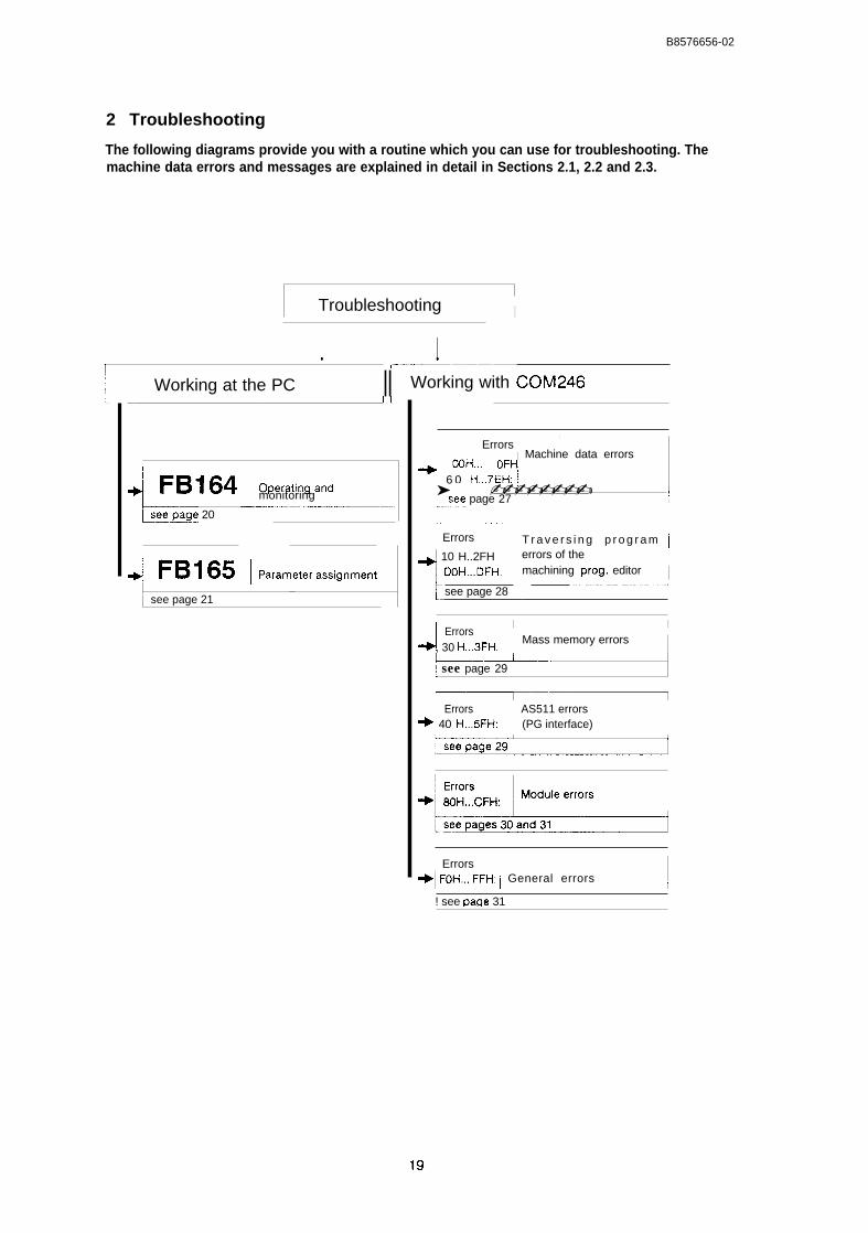
B8576656-02
2 Troubleshooting
The following diagrams provide you with a routine which you can use for troubleshooting. Themachine data errors and messages are explained in detail in Sections 2.1, 2.2 and 2.3.
Troubleshooting !I
, I( —--————
Working at the PC II Working with COM246
4 FB164 I owath~m~~ monitoring2—-------------- ..—-———–—–—–.
Lage 20
~ FB165 ~parameter=siwme.tsee page 21
I
I Errors ~~ Machine data errors
+! OOH... OFH! 6 0 H.7EH: ~➤ ✍✍�� ✍✍✍✍✍✍✍✍ ✛~,see page 27 1
~.. . . -..–----––~ Errors
~~ 10 H..2FH
I
DOH..DFH:
see page 28
T r a v e r s i n g p r o g r a m Ierrors of themachining prog. editor I—“””~
J ErrorsI I
, 30 H...3FH:Mass memory errors I
--–.~.–.[ see page 29
Errors+ 40 H,..5FH:
AS511 errors(PG interface) 1
I Errors+1 FoH,,, FFH: i General errors ~
! see paqe 31 I
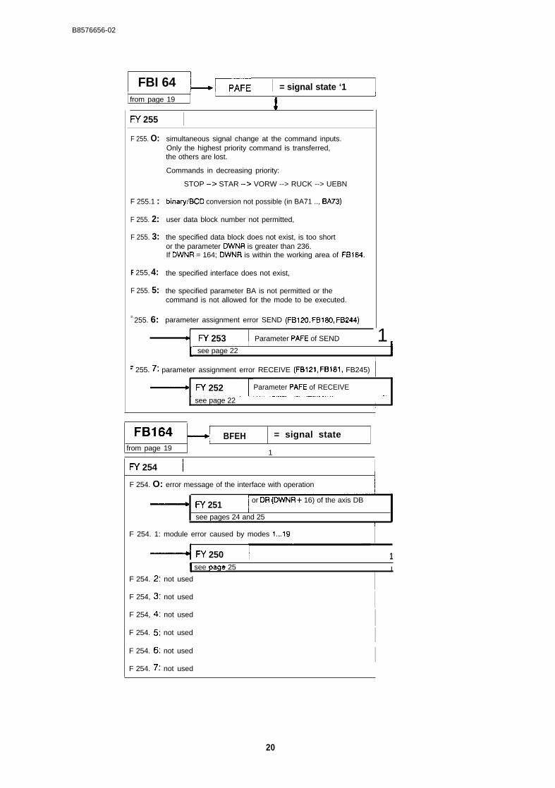
B8576656-02
FBI 64 ~~E = signal state ‘1I I
from page 19I
I+
FY 255 IF 255. O:
F 255.1 :
F 255. 2:
F 255. 3:
F 255, 4:
F 255. 5:
= 255. 6:
simultaneous signal change at the command inputs.Only the highest priority command is transferred,the others are lost.
Commands in decreasing priority:
STOP -> STAR -> VORW --> RUCK --> UEBN
binary/BCD conversion not possible (in BA71 .., BA73)
user data block number not permitted,
the specified data block does not exist, is too shortor the parameter DWNR is greater than 236.If DWNR = 164; DWNR is within the working area of FB164.
the specified interface does not exist,
the specified parameter BA is not permitted or thecommand is not allowed for the mode to be executed.
parameter assignment error SEND (FB120, FB180, FB244)
d W 253 Parameter PAFE of SEND 1I1 see page 22 I
I
‘ 255. T: parameter assignment error RECEIVE (FB121, FB181, FB245)
~ FY 252 Parameter PAFE of RECEIVE
see page 221
FB164 BFEH = signal statefrom page 19
1
FY 254 1 IF 254. O: error message of the interface with operation It
~ FY 251 or DR (DWNR+ 16) of the axis DB
see pages 24 and 25[
F 254. 1: module error caused by modes 1...19
FY 250 1I see page 25 I
F 254. 2: not used
F 254, 3: not used IF 254, 4: not used IF 254. 5: not used IiF 254. 6: not used IF 254. 7: not used \
20
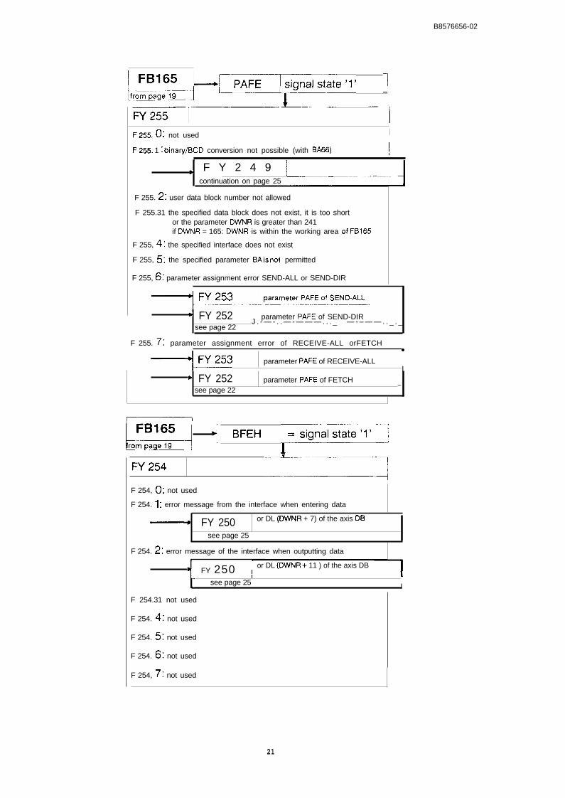
I
B8576656-02
——
ksi&aL~--pa’e’” 1F255. 0: not used I
F255. 1 I binary/BCD conversion not possible (with BA66) I,
F Y 2 4 9 I&continuation on page 25 –---+
F 255. z: user data block number not allowed
F 255.31 the specified data block does not exist, it is too shortor the parameter DWNR is greater than 241if DWNR = 165: DWNR is within the working area of FB165
F 255, q I the specified interface does not exist
F 255, s: the specified parameter BA k not permitted
F 255, G: parameter assignment error SEND-ALL or SEND-DIR
‘ FY 252 i parameter PAFE of SEND-DIRJ . - — - . . — - — — — . . . _ — - – — — . . _ . _
see page 22
1 F 255. T: parameter assignment error of RECEIVE-ALL orFETCH ~●
1 +FY253 parameter PAFE of RECEIVE-ALLI
‘ FY 252 parameter PAFE of FETCHsee page 22
—
Q 4 ‘F’” 1=s’’”’’s’’’’’l’-lFY254
“~F 254, (): not used
F 254. 1 : error message from the interface when entering data
FY 250 or DL (DWNR + 7) of the axis DB
see page 25
F 254. z: error message of the interface when outputting data
‘1 FY 250 or DL (DWNR+ 11 ) of the axis DBI!
t-see page 25 I
F 254.31 not used
F 254. q; not used
F 254. s: not used
F 254. 6: not used
F 254, 7’: not used
21
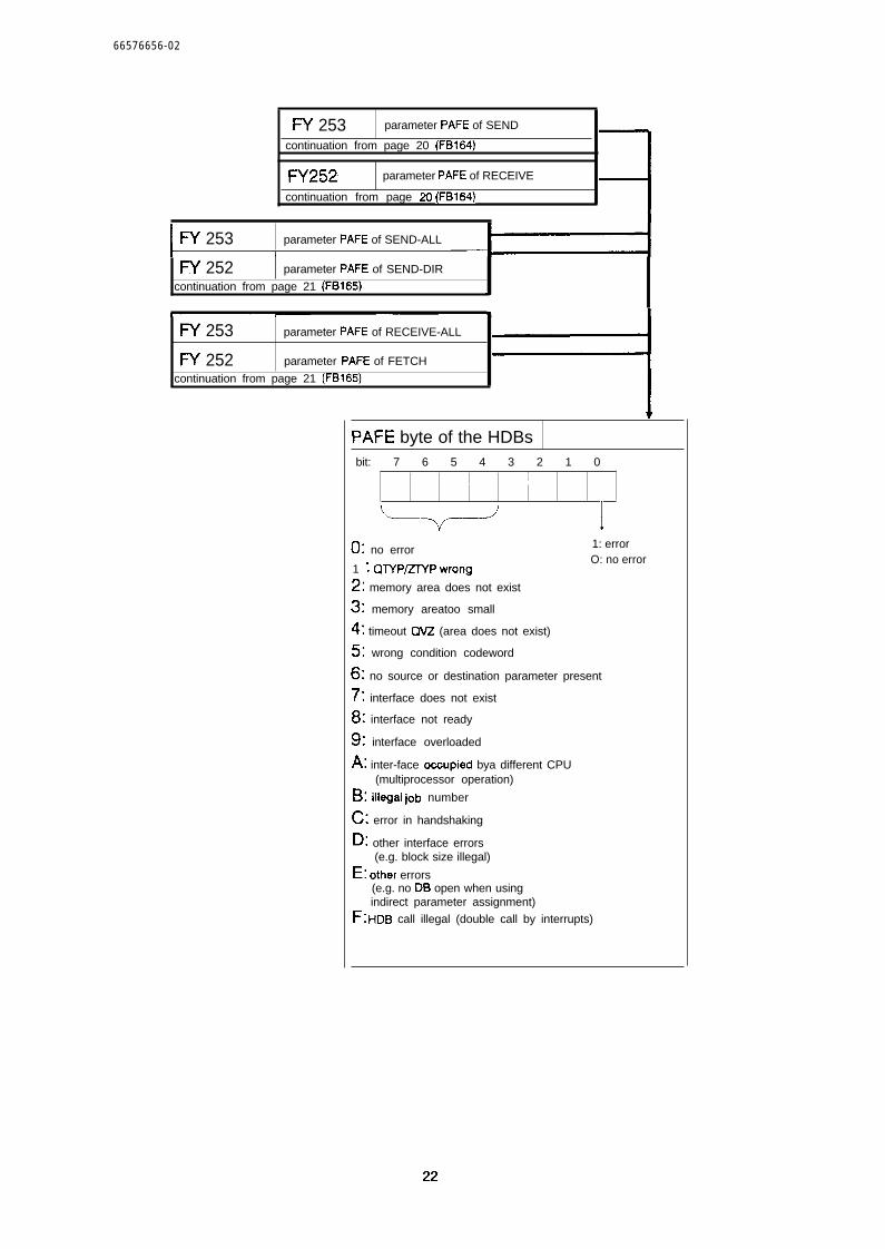
66576656-02
FY 253 parameter PAFE of SEND
continuation from page 20 (FB164)
FY252 parameter PAFE of RECEIVE
continuation from page 20 (FB164)
I
FY 253 parameter PAFE of SEND-ALLI
W 252 parameter PAFE of SEND-DIR
continuation from page 21 (FB165) *
FY 253 parameter PAFE of RECEIVE-ALL
FY 252 parameter PAFE of FETCH
continuation from page 21 (FB165)
-1v
PAFE byte of the HDBsbit: 7 6 5 4 3 2 1 0
I
1
0: no error 1: error
1 I QTYP/ZTYPwrongO: no error
z: memory area does not exist
3: memory areatoo small
Q: timeout CM? (area does not exist)
s: wrong condition codeword
6: no source or destination parameter present
T: interface does not exist
8: interface not ready
91 interface overloaded
A: inter-face ocoupied bya different CPU(multiprocessor operation)
B: illegal job number
C: error in handshaking
D: other interface errors(e.g. block size illegal)
E: other errors(e.g. no DB open when usingindirect parameter assignment)
F: HI)B call illegal (double call by interrupts)
22
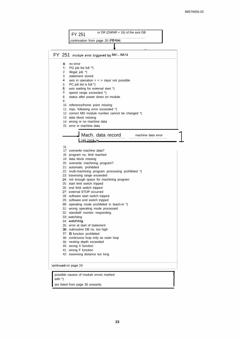
B8576656-02
FY 251 or DR (DWNR + 16) of the axis DB
continuation from page 20 (FB164)
! —
FY 251 module error t@wed W BAI...BAI9 Io:1:2:3:4:5:6:7:8:9:10:11:12:13:14:15;
no errorPG job list full *)illegal job *)statement storedaxis in operation = = > input not possiblePC job list is full *)axis waiting for external start *)speed range exceeded *)status after power down on module
reference/home point missingmax. following error exceeded *)correct MD module number cannot be changed *)data block missingwrong or no machine dataerror in machine data
- Mach. data record machine data error
161718:19:20:21:22:23:24:25:26:27:28:29:3031:32:
[ ‘we Q&W ‘6
overwrite machine data?program no, limit reacheddata block missingoverwrite machining program?automatic prohibitedmulti-machining program processing prohibited *)traversing range exceedednot enough space for machining programstart limit switch trippedend limit switch trippedexternal STOP occurredsoftware start switch trippedsoftware end switch trippedoperating mode prohibited in teach-in *)wrong operating mode processedstandstill monitor responding
33: watchdog34:35:36:37:38:39:40:41:42:
watchdo-gerror at start of statementsubroutine DB no. too highG function prohibitedcontinuous loop only as outer loopnesting depth exceededwrong X functionwrong F functiontraversing distance too long
:ontinued on page 24
possible causes of module errors marked Iwith *)
are listed from page 35 onwards,
1
23
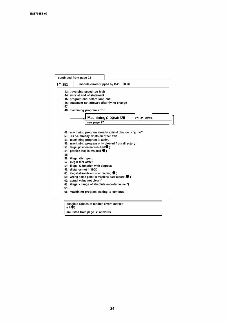
B8576656-02
continued from page 23
W 251 module errors tripped by BA1 ...BA19
43: traversing speed too high44: error at end of statement45: program end before loop end46: statement not aHowed after flying change47:48: machining program error
Machining programDB syntax errors
49:50:51:52:53:54:55:56:57:58:59:60:61:62:63:64:
see page 27
machining program already exists! change prog. no?DB no. already exists on other axismachining program is activemachining program only cleared from directorytarget position not reached ● )position loop interrupted ● )
illegal dist. spec.illegal tool offsetillegal G function with degreesdistance not in BCDillegal absolute encoder reading ● )wrong home point in machine data record ● )actual value not clear *)illegal change of absolute encoder value *)
65: machining program waiting to continue
1
I possible causes of module errors markedwith ● )
are listed from page 35 onwards I
24
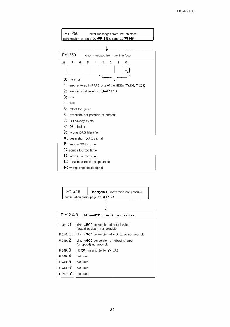
B8576656-02
FY 250 error messages from the interface
continuation of page 20 (FB164) & page 21 (FB165) i
I
FY 250 error message from the interface
bit: 7 6 5 4 3 2 1 0
ILI 1/ -J
o:1:
2:3:4:5:6:7:8:9:A:B:n.
no error +-’
error entered in PAFE byte of the HDBs (FY252/iV253)
error in module error byte (FY251)
free
free
offset too great
execution not possible at present
DB already exists
DB missing
wrong ORG identifier
destination DB too small
source DB too small
~. source DB too large
D: area in PC too smatl
E: area blocked for output/input
F: wrong checkback signal
FY 249 binary/BCD conversion not possible
continuation from page 21 (FB165)
~—1
I F Y 2 4 9 I binav/BCDconversionnotpossible
I F 249. O:
F 249, 1 :
F 249. 2:
I
F 249. 3:F 249. 4:F 249. 5:F 249, 6:F 249, 7:
binary/BCD conversion of actual value(actual position) not possible
binary/BCD conversion of dist. to go not possible
binarv/BCD conversion of following error(or speed) not possible
FB164 missing (only S5
not used
not used
not used
not used
15U)
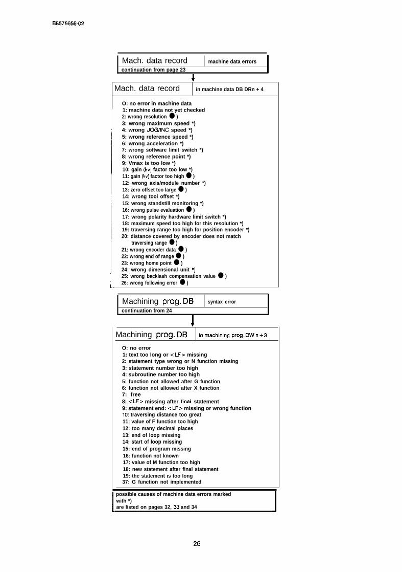
B8576656-02
Mach. data record machine data errors
continuation from page 23
4.Mach. data record in machine data DB DRn + 4
O: no error in machine data1: machine data not yet checked2: wrong resolution ● )3: wrong maximum speed *)4: wrong JOG/lNC speed *)5: wrong reference speed *)6: wrong acceleration *)7: wrong software limit switch *)8: wrong reference point *)9: Vmax is too low *)10: gain (kv) factor too low *)11: gain (kv) factor too high ● )12: wrong axis/module number *)13: zero offset too large ● )14: wrong tool offset *)15: wrong standstill monitoring *)16: wrong pulse evaluation ● )17: wrong polarity hardware limit switch *)18: maximum speed too high for this resolution *)19: traversing range too high for position encoder *)20: distance covered by encoder does not match
traversing range ● )21: wrong encoder data ● )22: wrong end of range ● )23: wrong home point ● )24: wrong dimensional unit *)25: wrong backlash compensation value ● )26: wrong following error ● )
Machining prog. DB syntax error
continuation from 24
I
Machining prog. DB in m=hinifw ww. Dwn+3
O: no error1: text too long or < LF> missing2: statement type wrong or N function missing3: statement number too high4: subroutine number too high5: function not allowed after G function6: function not allowed after X function7: free8: < LF> missing after final statement9: statement end: -= LF> missing or wrong function10: traversing distance too great11: value of F function too high12: too many decimal places13: end of loop missing14: start of loop missing15: end of program missing16: function not known17: value of M function too high18: new statement after final statement19: the statement is too long37: G function not implemented
possible causes of machine data errors markedwith *)are listed on pages 32, 33 and 34
26
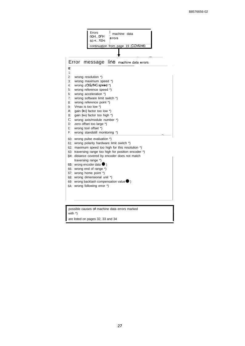
I
B8576656-02
Errors ~ machine dataoOH...OFH ~rror~60 H...7EH:
continuation from page 19 (COM246)
IError message he I machine data errors .-Jo:1:2:3:4:5:6:7:8:9:A:B:c:D:E:F:
60:61:62:63:64:
65:66:67;68:69:6A:
wrong resolution *)wrong maximum speed *)wrong JOG/lNC SPeed *)wrong reference speed *)wrong acceleration *)wrong software limit switch *)wrong reference point *)Vmax is too low *)gain (kv) factor too low *)gain (kv) factor too high *)wrong axis/module number *)zero offset too large *)wrong tool offset *)wrong standstill monitoring *) —..wrong pulse evaluation *)wrong polarity hardware limit switch *)maximum speed too high for this resolution *)traversing range too high for position encoder *)distance covered by encoder does not matchtraversing range *)wrong encoder data ● )wrong end of range *)wrong home point *)wrong dimensional unit *)wrong backlash compensation value ● )wrong following error *)
possible causes of machine data errors markedwith *)
are listed on pages 32, 33 and 34
27
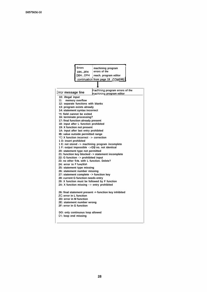
B8576656-02
Errors machining program10H...2FH errors of theDoH...DFH reach. program editor I
1
contmuatton from page 19 (CCIM 246)
I
:rror message lineachining program errors of theachining program editor
10: illegal input11: memory overflow12: separate functions with blanks13: program exists already14: statement syntax incorrect15: field cannot be exited16: terminate processing?17: final function already present18: input after L function prohibited19: X function not present1A: input after last entry prohibitedIB: value outside permitted rangeIC: X function incorrect -> correction1 D: insert prohibited1 E: not stored -> machining program incomplete1 F: output impossible -> DB no. not identical20: statement type not permitted21: function key blocked -> statement incomplete22: G function -> prohibited input23: no other fcts. with L function. Delete?24: error in Ffunction25: statement type missing26: statement number missing27: statement complete -> function key28: current G function needs entry29: X function must be followed by F function2A: X function missing -> entry prohibited
26: final statement present -> function key inhibited2C: error in L function2D: error in M function2E: statement number wrong2F: error in G function
DO: only continuous loop allowedDl: loop end missing
28

B8576656-02
-+
continuation from page 19 (COM246)
‘--–3G{G==IError message Ime
30:31:32:33:34:35:36:37:38:39:3A:3B:3C:
drive not definedextern. memory defectelement list missingdata block missingDE or file exists alreadyfile type not definedidentification headers not identicalexternal memory read-onlyfile read-onlynot enough buffer lengthnumber of allowed elements too largefile missing
3D: directory f;ll3E: diskette full3F: file not interpretable
Errors AS511 errors40 H...5FH: (PG interface)
continuation from page 19 (COM246)
1
Error message line AS511 errors—
40:41:42:43:44:45:
4a:
4C:
50:51:52:53:54:55:56:57:5a:
5A:
5D:5E:5F:
syntax error /name wrongnot alloweddata block missingoverwrite data block?data block missingdelete data block?
illegal value
cable not connected
data block missingcable not corm. at PGnot enough memory on modulewatchdog error moduletransfer errorerror in data transfererror in data transferBREAK receivedmod, not answering
wrong baud rate
parity erroroverflow errorframe error
29

B8576656-02
Errors80 Ff...CFH:
Module errors
I
continuation from page 19 (COM 246) I
1.
Error message line module errors
80:81: PG job list is full *)82: illegal job *)83: statement stored84: axis in operation = = > input not possible85: PC job list is full86: axis waiting for external start *)87: speed range exceeded66: status after power down on module89:8A: reference/home point missing8B: max. following error exceeded *)8C: correct MD module number cannot be changed *)8D: data block missing8E: wrong or no machine data8F: error in machine data90: PG is offline91: overwrite machine data?92: program no. limit reached93: data block missing94: overwrite machining program?95: automatic prohibited96: multi-machining program processing prohibited *)97: traversing range exceeded98: not enough space for machining program99 start limit switch tripped9A: end limit switch tripped9B: external STOP occurred9C: software start limit switch tripped9D: software end limit switch tripped9E: operating mode prohibited in teach-in *)9F: wrong operating mode processedAO: standstill monitor respondingAl: watchdogA2: watchdogA3: error at start of statementA4: subroutine DB no. too largeA5: G function prohibitedA6: continuous loop only as outer loopA7: nesting depth excaededA6: wrong XfunctionA9: wrong F functionAA: traversing distance too longAB: traversing speed too highAC: error at statement endAD: program end before loop endAE: statement not allowed after flying changeAF:BO: machining program errorBl: machining program already exists! Change prog. no?
:ontinued on page 31
i ipossible causes of module errors markedwith *)
are listed from page 35 onwards.
30
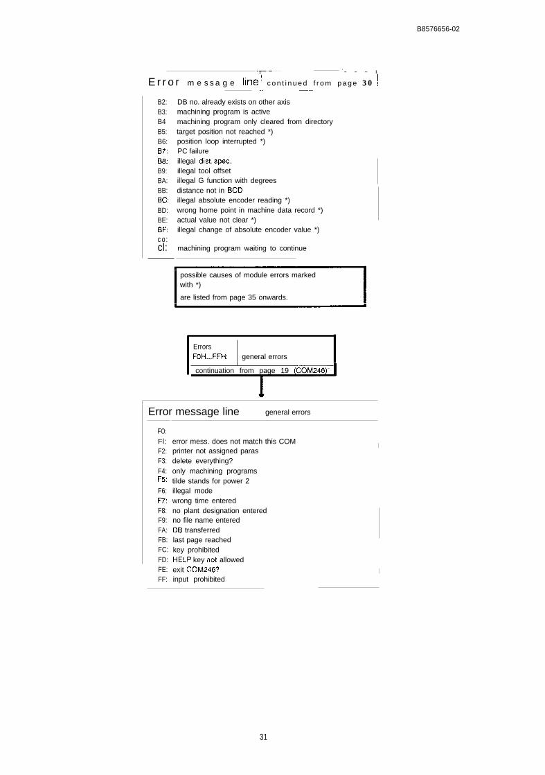
B8576656-02
..T.-..–..... .— ------- —— - - 1
E r r o r m e s s a g e lifle ! c o n t i n u e d f r o m p a g e 3 0 !
B2:B3:B4B5:B6:B7:B8:B9:BA:BB:BC:BD:BE:BF:co:cl:
.. ————. —..
DB no. already exists on other axismachining program is activemachining program only cleared from directorytarget position not reached *)position loop interrupted *)PC failureillegal dist, spec,illegal tool offsetillegal G function with degreesdistance not in BCDillegal absolute encoder reading *)wrong home point in machine data record *)actual value not clear *)illegal change of absolute encoder value *)
machining program waiting to continue
possible causes of module errors markedwith *)
are listed from page 35 onwards.
ErrorsFOH...FFH: general errors
continuation from page 19 (COM246) –
Error message line general errors
FO:Fl:F2:F3:F4:F~:
F6:F-7:F8:F9:FA:FB:FC:FD:FE:FF:
error mess. does not match this COM !I
printer not assigned parasdelete everything? !only machining programs Itilde stands for power 2 !illegal mode
Iwrong time enteredno plant designation entered
\
no file name enteredDB transferredlast page reachedkey prohibitedHELP key not allowedexit COM246? Iinput prohibited
31

68576656-02
2.1 Machine Data Errors and their Causes
When machine data are transferred to the module, they are checked on the module. If a machinedata error is recognized, the error “error in machine data” is set and the machine data record ismarked as containing errors by entering the number of the machine data error in the data re-cord. The C0M246 software package evaluates this error number and displays the error in plaintext in the error message line on the PG. When transferring data with FB165 (= > “StandardFunction Blocks FB164 and FB165, User’s Guide”) the number must be read out of the data re-cord when an error was recognized in the machine data record.
●
●
●
●
●
●
●
●
●
Error 2 (COM246: F02H; PC: 2) “wrong resolution”The resolution resulting by dividing the “distance per encoder revolution” by “pulses/stepsper encoder revolution” must be within the limits 0.1.,.99.9 um/pul (incremental version) or0.1...100 urn/step (absolute version). The parameter “distance per encoder revolution”[1 ...400000 urn], and with the incremental version, the range of values of the parameter“pulses per encoder revolution” [1...65000 urn] is also monitored. The selected traversingrange must always be greater than twice the resolution.
Error 3 (COM246: F03H; PC: 3) Wrong maximum speed”The specified speed must be in the range 1...65000.
Error 4 (COM246: F04H; PC: 4) “wrong JOG/lNC speed”Each of the speeds must be greater than or equal to 1 and less than or equal to theassigned maximum speed.
Error 5 (CC) M246: F05H; PC: 5) Wrong reference speed”With the IP246 (incremental version), the reference speed 1 must be greater than or equalto 1 and less than or equal to the assigned maximum speed. The reference speed 2 mustalso be greater than 1, however, less than or equal to reference speed 1.
Error 6 (C0M246: F06H; PC: 6) “wrong acceleration”The maximum acceleration must be greater than or equal to 10 and less than or equal to9999 mm/sec2 (0.1 inch/sec2, degrees/sec2). The other acceleration or deceleration ratesmust also be greater than or equal to 10, however, less than or equal to the maximumacceleration.
Error 7 (COM246: F07H; PC: 7) “wrong software limit switch”The traversing range of a linear axis is fixed by the coordinates of the “software start limitswitch” and “software end Iimfi switch”. The coordinates of the software limit switchesmust be different - the start always less than the end - and within the range +/-40 m (+/-4000 inches, +/- 40000 degrees).
Error 8 (COM246: F08H; PC: 8) “wrong reference point”The coordinate of the reference point for the incremental version must be less than orequal to the coordinate of the “software end limit switch” and greater than or equal to thecoordinate of the “software start limit switch”.
Error 9 (CC) M246: F09H; PC: 9) “vm~, is too low”The lower value of the programmed maximum speed depends on the resolution R[um/pul] (“distance per encoder revolution’ ’t’pulses per encoder revolution”). vrn~[mm/min] must be greater than 4. R [um/puls].
Error 10 (COM246: FOAH; PC: 10) “gain (kv) factor too IoWThe lower limit of the gain factor is 0.1 [1/secJ.
32
B8576656-02
●
●
●
●
●
o
●
e
●
Error 11 (COM246: FOBH; PC: 11) “gain (kv) factor too high”The kv factor must be less than 100 [l/see] and must not be so high that a voltagecorresponding to the maximum speed is output when there is a control error of 1 pulse;i.e. the gain factor in l/see must be less than
Vmax [mm/min] .1000
R [urn/pulse] .60
Error 12 (COM246: FOCH; PC: 12) Wrong axis/module numbet”In mode 24 (“enter SYSID”), the IP246 is assigned a module number. COM246 executesmode 24 when F1 (BEGIN) is pressed in the presetting mask ( = > “Functions, ReferenceManual”, Section 3.18 “Enter SYSIDI’). When entering a machine data record to the IP246,this number is compared with the module number entered in the machine data record.The machine data record must contain the same module number.
Error 13 (COM246: FODH; PC: 13) “zero offset too large”Each zero point offset can have values in the total range of +/-40 m. When a zero pointoffset is executed, the coordinates of the software limit switches are correctedaccordingly, Following such a correction, the coordinates of the software limit switchesmust still be within the permitted range of +/-40 m ( +/+000 inches, +/-40000 degrees).
Error 14 (C0M246: FOEH; PC: 14) “wrong tool offset”The tool offset is limited to a value of +/-40 m. The coordinates of the software end limitswitch plus the tool offset and the coordinate of the software start limit switch plus the tooloffset must remain in the range +/-40 m (+/-4000 inches, +/-40000 degrees).Remember that tool offsets have a sign. If a rotary axis is being used, the tool offset mustalso be less than the traversing range fixed by the range limits.
Error 15 (COM246: FOFH; PC: 15) “wrong standstill monitoring”The range of values for the standstill monitoring is between 0.001 and 64.999 mm. It mustalso be less than the maximum following error.
Error 16 (COM246: F60H; PC: 16) “wrong pulse evaluation”Only single, double or quadruple evaluation of the signal of an incremental encoder ispermitted ( = > ‘“Fundamentals of Positioning, Reference Manual”, Section 4.2 “PositionDecoding and Travel Resolution”).
Error 17 (COM246: F61H; PC: 17) “wrong polarity hardware limit switch”The values “O” (NO, positive) and “l” (NC, negative) are permitted. The IP246 can onlyrecognize incorrect parameter assignment when neither hardware limit switch is trippedwhen the machine data are entered. The hardware limit switches are also evaluated for arotary axis. If no hardware limit switches are connected, you must program NO switches.
Error 18 (C0M246: F62H; PC: 18) “maximum speed too high for this resolution”The counter chip on the incremental version can count pulse trains from encoders with 5V differential signals up to a maximum rate of 500 kHz. At the maximum speed andselected resolution [urn/pulse], this value is exceeded.
Error 19 (C0M246: F63H; PC: 19) “traversing range too high for position encoder”If a linear axis is being used with the absolute version, you must make sure that theabsolute position encoder can cover every coordinate which can be reached duringoperation. ( = > “Fundamentals of Positioning, Reference Manual”; Section 4.3 “TheTraversing Range” and Part 4 “Functions”; Section 3.4.2 “Set Reference Point”).
33
B8576656-02
Error 20 (CC) M246: F64H; PC: 20) “distance covered by encoder does not matchtraversing range”If a rotary axis is being used with the absolute version, you must make sure that the rangecovered by the absolute encoder exactly matches the traversing range ( = >“Fundamentals of Positioning, Reference Manual”; Section 4.3 “The Traversing Range”).
Error 21 (COM246: F65H; PC: 21) Wrong encoder data”The range of values of the parameter “number of revolutions” is 1...65000. The range ofvalues of the parameter “steps per encoder revolution” for the absolute version is2...65000, and only even numbers are allowed. The multiplication of the two values mustnot result in a value greater than 2‘. If the product is not equal to a power or 2, themodule assumes that you are using an absolute encoder supplying Gray excess-X code.This is, however, only permitted with a single turn encoder (= > “Fundamentals ofPositioning, Reference Manual”, Section 4.2 “Position Decoding and Travel Resolution”.
Error 22 (C0M246: F66H; PC: 22) “wrong end of range”This error only occurs with a rotary axis. The cause of the error is identical to that of error7.
Error 23 (COM246: F67H; PC: 23) “wrong home point”This error only occurs with the absolute version. The cause of the error is identical to thatof error 8.
Error 24 (C0M246: F68H; PC: 24) Wrong dimensional unit”The dimensional units available are metric (“l”), inches (“2”) and degrees (“3”) (= >“Fundamentals of Positioning, Reference Manual” Section 4.2 “Position Decoding andTravel Resolution”).
Error 25 (COM246: F69H; PC: 25) “wrong backlash compensation ValUe”The permitted range for the backlash compensation value is 0.001...64.999 mm.
34

B8576656-02
2.2 Module Errors and Possible Causes
This section deals with module errors and errors specific to the axis. Module errors occurring onthe positioning module IP246 are output both via the PC and via the PG interface. The messagesdisplayed by COM246 have an offset, so that the error numbers at the PG differ from those at thePC by 80H.
The COM246 software package also displays an additional set of error messages resulting fromcommunication between the COM246 software when operator input is made, from diskette/harddisk processing or from the interpretation of machine data and machining program errors.
The software of the IP246 generates two types of error messages for module errors:
● the actual axis errors which lead to a traversing movement being aborted and
● warnings or indications which are simply to inform the user (errors 1 to 9).
With the incremental version from firmware release A02,1 and with the absolute version, the axiserrors must be further divided as follows:
● axis errors, which lead to the traversing movement being aborted and the axis status“finished” being set
● axis errors, which lead to the traversing movement being aborted but then automaticallyswitch on the following error mode (mode 4).
If an axis error is displayed in COM246, not only the error number but also a message is dis-played, so that the cause of the error can normally be recognized immediately.
There are, however, some error messages which require further explanation to allow you to findthe cause of the error and to remedy it more quickly. Some error messages are therefore ex-plained in more detail.
●
●
●
●
●
Error 1 (PC: 1, COM246: 81 H) “PG job list is full”Owing to mechanical inertia, the module cannot execute the jobs as quickly as they arebeing entered. The last job entered from the PG has been lost and must be repeated.
Error 2 (PC: 2, COM246: 82H) “illegal job”The last job sent from the PC or PG either has no defined mode or is not feasible at thispoint. Example: starting an axis which is already running. The job is ignored.
Error 5 (PC: 5, COM246: 85H) “PC job list is full”Corresponds to error 81 from the point of view of the PC. The last job must be repeated.
Error 6 (PC: 6, COM246: 86H) “axis waiting for external start”The execution of the selected mode is blocked by a signal “l” at the digital input “externalstart/stop” ( = > “Fundamentals of Positioning, Reference Manual”, Section 7.4 “ExternalStart/Stop”).
Error 7 (PC: 7, COM246: 87H) “speed range exceeded”Either the specified override is outside the permitted range of values of 1...200%, or thespeed resulting from the selected (permitted) override exceeds the maximum speed. Thisonly occurs in the JOG modes and in incremental approach. The position moduleautomatically prevents the limit values being exceeded.
35
B6576656-02
● Error 11 (PC: 11, COM246: 8BH) “max. following error exceeded”The “maximum following error” selected in the machine data has been exceeded and thecurrent job aborted with a deceleration ramp. The position control loop remains switchedon and the axis stops after the existing following error has been eliminated. The followingerror monitoring only responds with the absolute version and incremental version fromfirmware version A02.1 when the maximum following error is exceeded, despite themovement of the axis or when the actual value no longer changes and the maximumfollowing error is selected so that it is exceeded at an analog value below 5 V. Possiblecauses are as follows:
- the load torque is too high,the acceleration is too high,
- the gain (kv) factor is too low,- the maximum following error has been set too low.
In these four cases it is possible to move the axis in the open-loop JOG mode. The machine datamust be suitably selected.
- The maximum speed and the resolution in the machine data are incorrectly selected, i.e.not matched to each other. Check by comparing the selected speed and the displayedspeed in the open-loop JOG mode.
With the incremental version of the IP246 with a firmware release less than A02.1, thefollowing error monitoring responds when
- the 24 V power supply is absent,- a position encoder is not connected, incorrectly connected or is defect.
(You can check this by moving the axis manually in the following error mode (mode 4)and observing whether there is a change of actual value, or if the speed is zero when youtraverse in mode 3 (JOG open-loop)).
- the analog output of the module is not connected,- the power unit is not switched on or not enabled, or- the axis is mechanically blocked by an obstacle or is jammed.
Error 12 (PC: 12, COM246: 8CH) “correct MD - module number cannot be changed”As soon as the positioning module has at least one correct machine data record, themodule number can no longer be changed. The number already stored can be read in thepresetting mask of COM246 ( = > “Functions, Reference Manual”, Section 3.19 “EnterSYSID” and Part 2 “Fundamentals of Positioning”, Section 4.8 “Other Parameters”).
Error 22 (PC: 22, COM246: 96H) “multi-machining program processing prohibited”It is not possible to store several machining programs in the memory of the IP246 at thesame time. This error occurs when an axis is creating a machining program in the teach-inmode and you attempt to transfer a second machining program to the other axis on themodule.
Error 30 (PC: 30, COM246: 9EH) “operating mode prohibited in teach-in”When the teach-in mode is active, only the JOG modes BA1 to BA3 and incremental jobsBA6 and BA7 are permitted.
36
B6576656-02
● Error 53 (Pc: 53, COM246: B5H) “target position tIOt reached”The position setpoint is already at the target. The actual position value is still outside theselected standstill monitoring value and is no longer approaching the target coordinateand the following error is less than the selected maximum following error. Possible causesare as follows:
- the standstill monitoring value is too small,- the gain (kv) factor is too small or- the drift of the power unit is too great (drift compensation, mode 18)- during the execution of a traversing job, the positioning control loop was interrupted
and the distance to go for the job is less than the maximum following error. If thedistance to go is, however, greater than the maximum following error, the errormessage “maximum following error exceeded” is set,
● Error 54 (PC: 54, COM246: B6H) “position loop interrupted”The actual position value is not changing although the analog voltage (speed setpoint)has exceeded the 5 V limit. The current job is abandoned by applying O V or a voltagecorresponding to a compensated drift to the analog output. The module thenautomatically switches to the following error mode (mode 4). The closed-loop positioncontroller is switched off in the following error mode. The following error mode can beterminated at any time. The closed-loop position controller is then switched on again. Thepossible causes are as follows:
the 24 V power supply is absent,- the position encoder is not connected, incorrectly connected or is defect,
the analog output of the module is not connected,- the power unit is not switched on or not enabled,- the axis is blocked mechanically by an obstacle or is jammed.
● Error EXI (PC fjo, C0M246: BCI+) “illegal absolute encoder reading”The detected absolute encoder value is not permitted. Possible causes areas follows:
the total number of steps of the absolute encoder used does not match the totalnumber of steps specified in the parameters,
- jumper Xl 7 ( = > Part 3 “Hardware”, Section 3.4 “Connecting Absolute PositionEncoders to the IP246-4UB “) is not correctly inserted,
- the encoder cable is subjecfio interference, is defect or not connected,the position encoder is defect,
- the power supply to the position encoder has failed.
One of these causes either results in an absolute position encoder value which can neveroccur with the selected encoder parameters (e.g. total number of steps of the absoluteencoder is greater than the specified total number of steps) or with a home point set, anabsolute encoder reading is received which indicates a position outside the usable range(= > “Fundamentals of Positioning, Reference Manual”, Section 4.3 “The TraversingRange”). Closed-loop position control is no longer possible. The current job is abandoned,O V or a voltage corresponding to the compensated drift is applied to the analog outputand the module switches automatically to the following error mode. The following errormode can (in this exceptional case) also be ended by changing the machine data. If theerror occurs again after changing the machine data, the module switches immediately tothe following error mode again.
37
B8576656-02
● Error 61 (PC: 61, COM246: BDH) “wrong home point in machine data record”The relationship of the home point coordinate to the absolute encoder reading as enteredin the machine data record is not permitted with this home point coordinate.
● Error 62 (PC: 62, COM246: BEH) “actual value not clear’When establishing the coordinate system, the current absolute encoder reading cannot beassigned a unique actual value, since this absolute encoder reading means a positionoutside the usable range ( = > “Fundamentals of Positioning, Reference Manual”, Section4.3 “The Traversing Range”).
The coordinate system is re-established with the absolute version of the IP246 in thefollowing situations::
mode 5 (“set home point”) is executedthe module starts up with valid machine datainput (transfer) of valid machine data to the module.
If this error occurs, the home point is deleted on the module. In the machine data recorditself a valid home point is nevertheless retained.
● Error 63 (PC: 63, COM246: BFH) “illegal change of absolute encoder values”The absolute encoder value has changed illegally. Possible causes are as follows:
the total number of steps of the absolute encoder being used is less than the totalnumber of steps selected in the parameters,there is feedback in the positioning control loop; i.e. with a positive analog voltage(speed setpoint) the encoder turns backwards and with a negative analog voltage itturns forwards,the encoder is not defect and is correctly connected. It turns when the 24 V powersupply from the module is absent or when the analog output of the module is notconnected, for example as a result of drift in the power unit,
- the encoder is defect, e.g. a track is missing,the power supply to the encoder has failed,the encoder cable is subject to interference, defector not connected.
Closed-loop position control is no longer possible, the current job is therefore interrupted,O V or a voltage corresponding to a compensated drift is applied to the analog output andthe module changes automatically to the following error mode. The following error mode(in this exceptional case) also be ended by changing the machine data.
2.3 PG Interface Errors
● Error 53H “watch dog error module”This error only appears on the PG interface, i.e. in COM246 and indicates situations inwhich there is no connection established to the positioning module. The possible causesare as follows:
the connecting cable is not inserted or there is a wire break- the positioning module has no power supply.
38
B8576656-02
3 Supplementary Notes
When using the IP246 positioning module there are several characteristics of the SIMATIC S5system which must be taken into account. The following sections deal with these characteristics.
3.1 Keyboard Character Buffer
The keyboards of the programmers have a buffer in which characters entered at the keyboardare temporarily stored when characters are entered more quickly than they can be processed.This can become apparent in the test mask of COM246 when commands are entered, for ex-ample, a fast sequence of “forwards” and “reverse” commands is entered in the JOG mode. Theexecution then lags behind the input. A stop command can only be executed when all the com-mands previously stored in the character buffer have already been processed.
3.2 Multiprocessor Operation
The S5 135U programmable controller is designed for multiprocessor operation. Several R pro-cessors could access the same positioning module independently, This is not permitted with theIP246 positioning module.
3.3 Restarts
A reset pulse on the bus resets both the incremental and absolute versions of the IP246. A cur-rent job is then no longer active, just as if the power had been switched off and on again.
The start-up characteristics of function blocks FB164 and FB165 are discussed in “ProgrammingInstructions IP246”. The IP246 positioning module reacts as follows when it is restarted:
Incremental version of the IP246:
Following each restart of the module, the reference point is deleted and the following error modeis active. If the battery back-up of the programmable controller was absent (the module was re-moved), all the machine data and machining programs on the IP246 are lost, a compensateddrift, zero point offsets and tool length offsets are also deleted. If the module was backed up bythe battery, the machine data remain valid. The reference point coordinate is then signalled asthe actual value.
39

BS576656-02
Absolute version of the IP246:
A home point is only lost if the module is not backed up by the PC battery. If the battery back-upof the programmable controller was absent (the module was removed) as with the incrementalversion, all the machine data and machining programs on the IP246 are lost, the home point, acompensated drift, zero point offsets and tool length offsets are also deleted. If the module wasbacked up by the battery, the machine data remain valid. If the home point was set, the absoluteposition of the axis is signalled immediately.
If no home point was set before the restart (module backed up by the battery), the home pointcoordinate is signalled as the actual value.
40

B6576656-02
Troubleshooting Questionnaire
If, despite careful installation and programming, you still encounter problems with positioningoperations and cannot localize the problem, please follow the routine outlined below:
Before calling your branch representative, please complete the questionnaire so that thenecessary information is readily available. The more exact the description of the problemand the events leading up to it, the faster your representative will be able to help you.
11) Which moduleareyou using? I
IP246 order no: 6ES5 246- 4UVersion marked:Firmware issue displayed by COM:
12) Which COM are you using? I
Order no: 6ES5 8—- 5—
Version issue: A——
13) Which PG are you using? I
PG:Version:
4) Which PG/EU are you using?
Pc:EU:Interface module:
Power supply:
41
B8576656-02
15) System components I
(please enter order numbers)
Pc:cc:Ps:
CPU:
Slot number:
1 2 6
—
7 8 9 10 11 12 13 14 15 16 17 18 19 20 21
—
—
Version
EU:Ps:
Interface module pair:
Slot number:
31 2 4 5 6 7 8 9 10 11 12 13 14 15 16 17 18 19 20 21—
Version
Have the drive specifications, machine data and any machining programs ready(see machine data planning or print out this data).
Make sure you know the jumper and switch settings on the module.
42
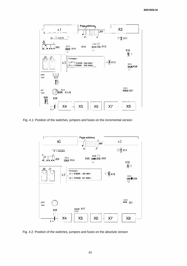
B8576656-02
~–..-——
2 7......1 r- ~~Page address
—..L _
x l.—. ..-—. .-. -. ——-. m“--”l-— 3
! ● = pressed 27. .2J1,— —-—-- --—---—— Cfqxll
L.
AFF‘use
AT‘use
X20
II● 1● 2.3
h=Ix3 ]Jf = > S79200 G62 A~f,
J3 = > S79200 - G62 As021—
6 .1mJ63 ~x14 x15 +#Jx13
Xlo
E
4X12 3 2 1
Y
● X16
“~-
0● 3:2
1
0
.,. :.*, 3 2 1
j. @ CE!EEI X 1 8
X19
3 2 1
ECEIX21
Fig. 4.1: Position of the switches, jumpers and fuses on the incremental version
xl 7. .1
J64x2
● I27. .21
:-.–~risseded :
6 .1
mJ63
J3 J1
I!Tl
o. . .?A5T‘use -
X19
#
1 2 33 2 1 X15 ● X13~x14
x3 J Firmware:
JI = S79200 - G8 A901/
) J3 = S79200 -G8 A9021
.-
= X171 2 3
4X12
m
Xlo
E
3 2 1
Y
● X16
1 2 3
LmEl x21
Fig. 4.2: Position of the switches, jumpers and fuses on the absolute version
43

B8576656-02
/6) Whatisgoing w r o n g ? I
7) Which error messages were output by theCOM software? I
8) Which error message is set at the outputof the standard function block? I
9) Which error numbers are entered inthe appropriate flag bytes?
10) Is the error reproducible?
11) Does the error occur sporadically?
12) Does the error occur when operating themodule from the PG as well as from the PC?
I 13) Which modes are being used? I
14) In which modes does the error occur?

I
68576656-02
15) When the positioning is incorrect, is thedistance travelled I- always too long
(= > possibly IOSS of pulses on the encoder lines or the encoder coupling is loose),- always too short,
(=> possibiy interference pulses coupled into the encoder lines),- always wrong by the same amount?
16) Does the error only occur with a particularsequence of jobs?
117) Whattypeofaxisare you using? I
Rotary axis: (o)
Linear axis:Vertical axis: — (0)Horizontal axis: (o)
118) What kind ofdriveareyou using? I
DC drive:
AC drive:
(0)
(o)
Rated speed: rpm
Adjusted to: rpm
for 10 V signal input
Manufacturer:Type:

68576656-02
119) Istheretransrnissicm? I
Type of transmission
Belt (o)Gear wheel (o)Chain (o)
Transmission ratio:
20) Which power unit are you using?
Manufacturer:Type:
Is the power unit adjusted to the IP246?
(Yes (0) /No (0))
How great is the axis drift in BA4? mV
Are the analog lines from the 1P to the power unit shielded twisted pairs wired as
shown in the manual?(Yes (0) /No (0) )
21) What type of position encoders are you using?
Absolute position encoder
Manufacturer:Type:
Single turn ( O ) / Multiturn ( O )If multiturn, number of revolutions:
Steps per revolution:Code used:
Incremental position encoder
ManufacturerType:
B8576656-02
ResolverManufacturer:
Type:
Number of pulses per revolution:
Measuring multiplexer with multiplication factor:
Was the encoder mounted directly on drive?(Yes (0) /No (0))
if not, brief description of the mounting
Wiring shielded and in twisted pairs for symmetrical encoders?(Yes (0) /No (0) )
Are there any sources of high-frequency interference (e.g. frequency converter)in the vicinity of the IP246 or its signal lines, or were the signal lines and power lines
laid parallel and close together?
(Yes ( O ) /No(O))
22) Is the module outputting an analog voltagealthough it has no traversing job? I
(Yes (0) /No (0))
23) When using externally ventilated IP246modules in the S5 115U is there anadditional fan?
(Yes (0) /No (0))
]24) Is FB164 called once per cycle and axis? I
(Yes (0) /No (0))
Jobs triggered by momentary pulse?
(Yes (0) /No (0))
47

B8576656-02
Which error messages are displayed?
25) Are the scratchpad flags beingsaved in the interrupting OBS? I
(Yes (0) /No (0))

SIEMENS
SIMATIC S51P 246 Positioning Module Incremental
AbsoluteList of Key Words
Index
6ES5246-4UA31 / -4UA416ES5246-4UBI 1 / -4UB21
C79000-B8576-C657 -02
B 8 5 7 6 6 5 7 - 0 2
Index
A
Absolute position encoder . . . . . . . . . . . . . . . . . . . . . . . . . . . . . . . . . . . . . . . . . . . . . . . . . . . . . . . . . . . . . . . . . . . . . . ~. ~. ~...,, . . . . . . . . . . . . . . . . . . ~.... ~. 2-26Absolute position encoders (current sinking) ...........,.,,,,,.,..,, . . . . . . . . . . . . . . . . . . . . . . . . . . . . . . . . . . . . . . . . ~....... 2-18Absolute position encoders (current sourcing) . . . . . . . . . . . . . . . . . . . . . . . . . . . . . . . . . . . . . . . . . . . . . . . . . . . . . . . . . . . . ~..... 2-18Acceleration forwards . . . . . . . . . . . . . . . . . . . . . . . . . . . . . . . . . . . . . . . . . . . . . . . . . . . . . . . . . . . . . . . . . . . . . . . . . . . . . . . . . . . . . . . . . . . . . . . . . . . . . . . . . . .2-34, 5-26Acceleration reverse . . . . . . . . . . . . . . . . . . . . . . . . . . . . . . . . . . . . . . . . . . . . . . . . . . . . . . . . . . . . . . . . . . . . . . . . . . . . . . . . . . . . . . . . . . . . . . . . . ............2-34, 5-26Actual position value . . . . . . . . . . . . . . . . . . . . . . . . . . . . . . . . . . . . . . . . . . . . . . . . . . . . . . . . . . . . . . . . . . . . . . . . . . . . . . . . . . . . . . . . . . . . . . . . . . . . . . . . . . . . . . .........5 -44Actual value . . . . . . . . . . . . . . . . . . . . . . . . . . . . . . . . . . . . . . . . . . . . . . . . . . . . . . . . . . . . . . . . . . . . . . . . . . . . . . . . . . . . . . . . . . . . . . . . . . . . . . . . . . . . . . . . . . . . . ................5 -55Actual value display mode . . . . . . . . . . . . . . . . . . . . . . . . . . . . . . . . . . . . . . . . . . . . . . . . . . . . . . . . . . . . . . . . . . . . . . . . . . . . . . . . . . . . . . . . . . . . . . . ~... 5-55Actual value reading ....,, . . . . . . . . . . . . . . . . . . . . . . . . . . . . . . . . . . . . . . . . . . . . . . . . . . . . . . . . . . . . . . . . . . . . . . . . . . . . . . . . . . . . . . . . . . ............4-44, 6-53Analog output,,.. . . . . . . . . . . . . . . . . . . . . . . . . . . . . . . . . . . . . . . . . . . . . . . . . . . . . . . . . . . . . . . . . . . . . . . . . . . . . . . . . . . . . . . . . . ~••. ~U‰ŒŒf™•ˆ•‚ŒŒV”•. ~U‰Œ€h™•ˆ• ‚ŒøÉ”•À¤•• . . . . . . . 2-16Approaching the target . . . . . . . . . . . . . . . . . . . . . . . . . . . . . . . . . . . . . . . . . . . . . . . . . . . . . . . . . . . . . . . . . . . . . . . . . . . . . . . . . . . . . . . . . . . . . . . . . . . . . . . . ~... ~... ~.. 2-68ASCII . . . . . . . . . . . . . . . . . . . . . . . . . . . . . . . . . . . . . . . . . . . . . . . . . . . . . . . . . . . . . . . . . . . . . . . . . . . . . . . . . . . . . . . . ...,,,,....,,,,, . . . . . . . . . . . . . . . ,,,...,.., ,,,..,.....,,5-44Automatic . . . . . . . . . . . . . . . . . . . . . . . . . . . . . . . . . . . . . . . . . . . . . . . . . . . . . . . . . . . . . . . . . . . . . . . . . . . . . . . . . . . . . . . . . . . . . . . . . . . . . . . . . . . . . . . . . . . . . . ............ 4-21Automatic single statement . . . . . . . . . . . . . . . . . . . . . . . . . . . . . . . . . . . . . . . . . . . . . . . . . . . . . . . . . . . . . . . . . . . . . . . . . . . . . . . . . . . . . . . . . . . . . . . . . . . . . . . . . . . . 4-22Auxiliary function. . . . . . . . . . . . . . . . . . . . . . . . . . . . . . . . . . . . . . . . . . . . . . . . . . . . . . . . . . . . . . . . . . . . . . . . . . . . . . . . . . . . . . . . . . . . . . . . . . . . . . . . . . . . . . . . . . . .5-46, 5-56Axis ..,,, . . . . . . . . . . . . . . . . . . . . . . . . . . . . . . . . . . . . . . . . . . . . . . . . . . . . . . . . . . . . . . . . . . . . . . . . . . . . . . . . . . . . . . . . . . . . . 2-41, 5-62, 5-64Axis selection .,, . . . . . . . . . . . . . . . . . . . . . . . . . . . . . . . . . . . . . . . . . . . . . . . . . . . . . . . . . . . . . . . . . . . . . . . . . . . . . . . . . . . . . . . . . . . . . . . . ~,.. ~. ~..... 5-23Axis status . . . . . . . . . . . . . . . . . . . . . . . . . . . . . . . . . . . . . . . . . . . . . . . . . . . . . . . . . . . . . . . . . . . . . . . . . . . . . . . . . . . . . . . . . . . . . . . . . . . . . . . . .. .4-4, 5-56
B
c
3
B8576657-02
Configuration mask . . . . . . . . . . . . . . . . . . . . . . . . . . . . . . . . . . . . . . . . . . . . . . . . . . . . . . . . . . . . . . . . . . . . . . . . . . . . . . . . . . . . . . . . . . . . . . . . . . . . . . . . . . .5-3, 5-13Configuration register,,,,.,..,., . . . . . . . . . . . . . . . . . . . . . . . . . . . . . . . . . . . . . . . . . . . . . . . . . . . . . . . . . . . . . . . . . . . . . . . . . . . . . . . . . . . . . . . . . . . . . . . . . . . . . . . . . 5-9Control algorithm . . . . . . . . . . . . . . . . . . . . . . . . . . . . . . . . . . . . . . . . . . . . . . . . . . . . . . . . . . . . . . . . . . . . . . . . . . . . . . . ...................2-1 4Controller parameters . . . . . . . . . . . . . . . . . . . . . . . . . . . . . . . . . . . . . . . . . . . . . . . . . . . . . . . . . . . . . . . . . . . . . . . . . . . . . . . . . . . . . . . . . . . . . . . ~...... ~.. 2-35Coordinates . . . . . . . . . . . . . . . . . . . . . . . . . . . . . . . . . . . . . . . . . . . . . . . . . . . . . . . . . . . . . . . . . . . . . . . . . . . . . . . . . . . . . . . . . . . . . . . . . . . . . . . . . . . ~..... 2-32Correction parameters., . . . . . . . . . . . . . . . . . . . . . . . . . . . . . . . . . . . . . . . . . . . . . . . . . . . . . . . . . . . . . . . . . . . . . . . . . . . . . . . . . . . ~... 2-38Current controller . . . . . . . . . . . . . . . . . . . . . . . . . . . . . . . . . . . . . . . . . . . . . . . . . . . . . . . . . . . . . . . . . . . . . . . . . . . . . . . . . . . . . . . . . . . . . . . . . . . . . . . . . . .....2 -13
D
E
F
File name . . . . . . . . . . . . . . . . . . . . . . . . . . . . . . . . . . . . . . . . . . . . . . . . . . . . . . . . . . . . . . . . . . . . . . . . . . . . . . . . . . . . . . . . . . . . . . . . . . . . . . . . . . . . . . . . . ... ,5-16, 5-42Final statement . . . . . . . . . . . . . . . . . . . . . . . . . . . . . . . . . . . . . . . . . . . . . . . . . . . . . . . . . . . . . . . . . . . . . . . . . . . . . . . . . . . . . . . . . . . . . . . . . . . . . . . . . ... 2-47Firmware. . . . . . . . . . . . . . . . . . . . . . . . . . . . . . . . . . . . . . . . . . . . . . . . . . . . . . . . . . . . . . . . . . . . . . . . . . . . . . . . . . . . . . . . . . . . . . . . . . . . . . . . . . . . . . . . . . . . . . . . . ................. 5-15Flying change . . . . . . . . . . . . . . . . . . . . . . . . . . . . . . . . . . . . . . . . . . . . . . . . . . . . . . . . . . . . . . . . . . . . . . . . . . . . . . . . . . . . . . . . . ,,.,,,,.2-49,2-50, 4-22,4-23Following error . . . . . . . . . . . . . . . . . . . . . . . . . . . . . . . . . . 2-10, 2-14, 2-35, 2-36, 4-44, 5-56
B8576657-02
G
H
i
J
JOG speed 2 . . . . . . . . . . . . . . . . . . . . . . . . . . . . . . . . . . . . . . . . . . . . . . . . . . . . . . . . . . . . . . . .. ......2-33JOG speed 2 fwd.... . . . . . . . . . . . . . . . . . . . . . . . . . . . . . . . . . . . . . . . . . . . . . . . . . . . . . . . . . . . . . . . . . . . . . . . . . . . . . . . . . . . . . . . . . . . . . . . . . . . . . . . . 5-35JOG speed 2 rev. . . . . . . . . . . . . . . . . . . . . . . . . . . . . . . . . . . . . . . . . . . . . . . . . . . . . . . . . . . . ...........,,,.,,,,............, ..,..5 -35Jumper- disable command output . . . . . . . . . . . . . . . . . . . . . . . . . . . . . . . . . . . . . . . . . . . . . . . . . . . . . . . . . . . . . . . . . . . . . . . . . . ......2 -70
K
L
M
0 8 5 7 6 6 5 7 - 0 2
N
N-function . . . . . . . . . . . . . . . . . . . ...........,..,.,,.,,,... . . . . . . . . . . . . . . . . . . . . . . . . . . . . . . . . . . . . . . . . . . . . . . 2-47Nesting . . . . . . . . . . . . . . . . . . . . . . . . . . . . . . . . . . . . . . . . . . . . . . . . . . . . . . . . . . . . . . . . . . . . . . . . . . . . . . . . . . . . . ................. 2-48Nesting depth . . . . . . . . . . . . . . . . . . . . . . . . . . . . . . . . . . . . . . . . . . . . . . . . . . .. . . . . . . . . . . . . . . . . . . . . . . . . . . . . . . . . . . . .2-48, 2-51Number of revolutions . . . . . . . . . . . . . . . . . . . . . . . . . . . . . . . . . . . . . . . . . . . . . . . . . . . . . . . . . . . . . . . . . . . . . . . . . . . . . . . . . . . . . . . . . . . . . . . . . . . 5-38Number of steps/r-ev. . . . . . . . . . . . . . . . . . . . . . . ...5-39Number of the machine data record . . . . . . . . . . . . . ,,,,.,,,,,...,.,,..,,,.,......,,, ...........2 -41
0
P
B8576657-02
PG . . . . . . . . . . . . . . . . . . . . . . . . . . . . . . . . . . . . . . . . . . . . . . . . . . . . . . . . . . . . . . . . . . . . . . . . . . . . . . . . . . . . . . . . . . . . . . . . . . . . . . . . . . . . . . . . . ................ ,.,....,.,...5-7PG interface,.,..........., . . . . . . . . . . . . . . . . . . . . . . . . . . . . . . . . . . . . . 7-22Planning the machine data,, ,.. . . . . . . . . . . . . . . . . . . . . . . . . . . . . . . . . . . . . . . . . . . . . . . . . . . . . . . ......7-5Plant designation ...., . . . . . . . . . . . . . . . . . . . . . . . . . . . . . . . . . . . . . . . . . . . . . . . . . . . . . . . . . . . . . . . . . . . . . . . . . . . . . . . . . . . . . . . . . . . . . . .........5 -16Polarity HW limit switch . . . . . . . . . . . . . . . . . . . . . . . . . . . . . . . . . . . . . . . . . . . . . . . . . . . . . . . . . . . . . . . . . . ................5 -37, 5-39Position control loop . . . . . . . . . . . . . . . . . . . . . . . . . . . . . . . . . . . . . . . . . . . . . . . . . . . . . . . . . . . . . . . . . . . . . . . . . . . . . . . . . . . . . . . . . . . . . . . . . . . . ..........7-3Position controller . . . . . . . . . . . . . . . . . . . . . . . . . . . . . . . . . . . . . . . . . . . . . . . . . . . . . . . . . . . . . . . . . . . . . . . . . . . . . . . . . . . . . . . . . . . . . . . . .............2-14, 5-10P o s i t i o n d e c o d i n g . . . . . . . . . . . . . . . . . . . . . . . . . . . . . . . . . . . . . . . . . . . . . . . . . . . . . . . . . . . . . . . . . . . . . . . . . . . . ,.,,,, .............2 -22Position encoder . . . . . . . . . . . . . . . . . . . . . . . . . . . . . . . . . . . . . . . . . . . . . . . . . . . . . . . . . . . . . . . . . . . . . . . . . ,3-I 4, 7-3Position reached . . . . . . . . . . . . . . . . . . . . . . . . . . . . . . . . . . . . . . . . . . . . . . . . . . . . . . . . . . . . . . . . . . . . . . . . . . . . . . ..................2 -67Position setpoint.....................,..,..,.. . . . . . . . . . . . . . . . . . . . . . . . . . . . . . . . . . . . . . . . . . . . ..... 2-10, 2-13, 2-67Positioning operation . . . . . . . . . . . . . . . . . . . . . . . . . . . . . . . . . . . . . . . . . . . . . . . . . . . . . . . 2-7Power reserves ....,.... . . . . . . . . . . . . . . . . . . . . . . . . . . . . . . . . . . . . . . . . . . . . . . . . . . . . . . . . . . . . . . . . . . . . . . 7-3Precontact . . . . . . . . . . . . . . . . . . . . . . . . . . . . . . . . . . . . . . . . . . . . . . . . . . . . . . . . . . . . . . . . . . . . . . . . . . . . 2-71, 4-14, 5-36Preparatory positioning condition . . . . . . . . . . . . . . . . . . . . . . . . . . . . . . . . . . . . . . . . . . 5-46Presetting mask. . . . . . . . . . . . . . . . . . . . . . . . . . . . . . . . . . . . . . . . . . . . . . . . . . . . . ....... 5-3, 5-14, 5-19PRINT M.DATA . . . . . . . . . . . . . . . . . . . . . . . . . . . . . . . ...................; . . . . . . . . . . . .,.....,.,.,.,......., . . . . . . . . . . . . . . . . . . . . . . . . . . . . . . . ..5-39Print type 1 . . . . . . . . . . . . . . . . . . . . . . . . . . . . . . . . . . . . . . . . . . . . . . . . . . . . . . . . . . . . . . . . . . . . . . . . . . . . . . ..,..,..,.,.............,.....,.......,.,,,,,,,,.,......5-43Print type 2 . . . . . . . . . . . . . . . . . . . . . . . . . . .. . . . . . . . . . . . . . . . . . . . . . . . . . . . . . . . . . . . . . . . . . . . . . . . . . . . ,., ............,,,,,,,.,, .,.5-44Print type 3 . . . . . . . . . . . . . . . . . . . . . . . . . . . . . . . . . . . . . . . . . . . . . . . . . . . . . . . . . . . . . . . . . . . . . . . . . . . . . . . . . . . . . . . . . . . . . . . . . . . . . . . . . . . . . . . . . . . ........... 5-44Printer . . . . . . . . . . . . . . . . . . . . . . . . . . . . . . . . . . . . . . . . . . . ........ ...........5-5- IBM or Epson . . . . . . . . . . . . . . . . . ..... 5-42- pT80.... . . . . . . . . . . . . ..,,,,,,,,,,.,..,,,, ..,,,,,.,......,,,., ,,,,,,.,.,,,,,,.,.,. ...,.,,,,,,,.,.,,,,, ,.,.,,,,,,..,...,.., .,,,..,,,...,,.,,,5 -42- PT88...... . . . . . . . . . . . . . . . . . . . . . . . . . . . . . . . . . . ,,,,,,,......., .,.,,,,, ,,,,..........,...,. ,,5-42PRINTER PARAMETER . . . . . . . . . . . . . . . . . . . . . . . . . . . .,...,,,...,,.....5 -42Printer parameter mask .,,,,.,,,,,,,,,,,.,,,,,,,,..,.,.,,.,..,.,,,,,,,,,,,,,,,..,.,, . . . . 5-43Printer type . . . . . . . . . . . . . . . . . . . . . . . . . . . . . . . . 5-42, 5-43Process interrupts,,,,,,, . . . . . . . . . . . . . . . . . . . . . . . . . . . . . . . . . . 6-7Program . . . . . . . . . . . . . . . . . . . . . . . . . . . . . . . . . . . . . . . . . . . . . . . . . ........... ...5-57Program end. . . . . . . . . . . . . . . . . . . . . . . . . . . . . . . . . . . . . . . . . . . . . . . . . . . . . . . . . . . . . . . . . . . . .,,,........2 -61Program header . . . . . . . . . . . . . . . . . . . . . . . . . . . . . . . . . . . . . . . . . . . . . . . . . . . . . . . . . . . . . . . . . . . . . . . . . . . . . . . . . . . . . . . . . . 2-46Program type ...........,,,,,., . . . . . . . . . . . . . . . . . . . . . . . . . . . . . . . . . . . . . . . . . . . . . . . . . . . . . . . . . . . . . . . . . . . . . . . . .......5 -46Programmed halt . . . . . . . . . . . . . . . . . . . . . . . . . . . . . . . . . . . . . . . . . . . . . . . . ................... 2-62, 4-22, 4-23Pulse evaluation .,, . . . . . . . . . . . . . . . . . . . . . . . . . . . . . . . . . . . . . . . . . . . . . . . . . . . . . 2-27Pulses/revolution . . . . . . . . . . . . . . . . . . . . . . . 5-37
R
Read actual values . . . . . . . . . . . . . . . . . . . . . . . . . . . . . . . . . . . . . . . . . . . . . . .....4 -44Reference coordinate . . . . . . . . . . . . . . . . . . . . . . . . . . . . . . . . . . . . . . . . ...4-13Reference direction . . . . . . . . . . . . . . . . . . . . . . . . . . . . . . . . . . . . . . . . . . . . . . . . . . . . . . . . . . . . . . . . . . . . . . . . . . . . . . ...........,...2 -33, 2-44Reference point . . . . . . . . . . . . . . . . . . . . . . . . . . . . . . . . . . . . . . . . . . . . . . . . . . . . . . . . . . . . . . . . . . . . . . . . . . . . . . . . . . . . . . . . . 2-29, 4-13, 5-22, 5-56, 7-16- setting . . . . . . . . . . . . . . . . . . . . . . . . . . . . . . . . . . . . . . . . . . . . . . . . . . . . . . . . . . . . . . . . . . . . . . . . . . . . . . . . . . . . .. ....2-30, 4-17Reference point approach . . . . . . . . . . . . . . . . . . . . . . . . . . . . . . . . . . . . . ...............,2 -29, 4-14Reference point direction, . . . . . . . . . . . . . . . . . . . . . . . . . . . . . . . . . . . . . . . . . . .................,4-1 4, 5-37Reference point/home point . . . . . . . . . . . . . . . . . . . . . . . . . . . . . . . . . . . . . . . . . . . . . . . . . . . . . . . . . . . . ~..., 5-31Reference signal., . . . . . . . . . . . . . . . . 4-14Reference speed 1 . . . . . . . . . . . . . . . . . . . . . . . . . . . . . . . . . . . . . . . . . . . . . . . . . . . . . . . . . . . . . . . . . . . . . . . . . . .,,,....,,,,.,..,........,.,........5-36Reference speed 2.,,..............,.... . . . . . . . . . . . . . . . . . . . . . . . . . . . . . . . . . . . . . . . . . . . . . . . . . 5-37Resolution . . . . . . . . . . . . . . . . . . . . . . . . . . . . . . . . . . . . . . . . . . . . . . . . . . . . . . . . . . . . . . . . . ... .2-22, 2-24Resolution factor . . . . . . . . . . . . . . . . . . . . . . . . . . . . . . . . . . . . . . . . . . . . . . . . . . . . . . . . . . 5-27Rotary axis . . . . . . . . . . . . . . . . . . . . . . . . . . . . . . . . . . . . . . . . . . . . . . . . . . . . . . . . . . . . . . . . . . . . . . . . . . . . . . . . . . . . . . . . .2-19, 2-21
0 8 5 7 6 6 5 7 - 0 2
s
T

u
v
w
Working copy . . . . . . . . . . . . . . . . . . . . . . . . . . . . . . . . . . . . . . . . . . . . . . . . . . . . . . . . . . . . . . . . . . . . . . . . . . . . . . . . . . . . . . . . . . . . . . . . . . . . . . . . . . .......................5-9
x
X-function . . . . . . . . . . . . . . . . . . . . . . . . . . . . . . . . . . . . . . . . . . . . . . . . . . . . . . . . . . . . . . . . . . . . . . . . . . . . . . . . . . 2-60, 5-46, 5-49
z
Zero marker . . . . . . . . . . . . . . . . . . . . . . . . . . . . . . . . . . . . . . . . . . . ...,.,,,...,,,,..,,,,,, . . . . . . . . . . . . . . . . . . . . . . . . . . . . . . . . . . . . . . . . . . . . . . . . . . . .,,4-14Zero offset . . . . . . . . . . . . . . . . . . . . . . . . . . . . . . . . . . . . . . . . . . . . . . . . . . . . . . . 2-38, 2-41, 2-56, 5-22, 5-33- absolute . . . . . . . . . . . . . . . . . . . . . . . . . . . . . . . . . . . . . . . . . . . . . . . . . . . . . . . . .................4 -26- relative . . . . . . . . . . . . . . . . . . . . . ,,,,,,,,,,..,,....,..,... . . . . . . . . . . . . . . . . . . . . . . . . . . . . . . . . . . . . . . . . . ..............4 -28Zero point adjustment ..,.,,,,.,,. . . . . . . . . . . . . . . . . . . . . . . . . . . . . . . . . . . . . . . . . . . . . . . . . . . . . . . . . . . . . . . . . . . ...............4 -18