Drilling and Well Servicing Equipment - Acewelacewel.com/api/API 7K - 2010 Drilling and Well...
120
Drilling and Well Servicing Equipment API SPECIFICATION 7K FIFTH EDITION, JUNE 2010 EFFECTIVE DATE: DECEMBER 1, 2010 ERRATA: AUGUST 2010
Transcript of Drilling and Well Servicing Equipment - Acewelacewel.com/api/API 7K - 2010 Drilling and Well...
Drilling and Well Servicing Equipment
API SPECIFICATION 7KFIFTH EDITION, JUNE 2010
EFFECTIVE DATE: DECEMBER 1, 2010
ERRATA: AUGUST 2010

--``,``,```,,`````,`,,`,`,``,,`,-`-`,,`,,`,`,,`---

Drilling and Well Servicing Equipment
Upstream Segment
API SPECIFICATION 7KFIFTH EDITION, JUNE 2010
EFFECTIVE DATE: DECEMBER 1, 2010
ERRATA: AUGUST 2010
--``,``,```,,`````,`,,`,`,``,,`,-`-`,,`,,`,`,,`---
Special Notes
API publications necessarily address problems of a general nature. With respect to particular circumstances, local,state, and federal laws and regulations should be reviewed.
Neither API nor any of API's employees, subcontractors, consultants, committees, or other assignees make anywarranty or representation, either express or implied, with respect to the accuracy, completeness, or usefulness of theinformation contained herein, or assume any liability or responsibility for any use, or the results of such use, of anyinformation or process disclosed in this publication. Neither API nor any of API's employees, subcontractors,consultants, or other assignees represent that use of this publication would not infringe upon privately owned rights.
API publications may be used by anyone desiring to do so. Every effort has been made by the Institute to assure theaccuracy and reliability of the data contained in them; however, the Institute makes no representation, warranty, orguarantee in connection with this publication and hereby expressly disclaims any liability or responsibility for loss ordamage resulting from its use or for the violation of any authorities having jurisdiction with which this publication mayconflict.
API publications are published to facilitate the broad availability of proven, sound engineering and operatingpractices. These publications are not intended to obviate the need for applying sound engineering judgmentregarding when and where these publications should be utilized. The formulation and publication of API publicationsis not intended in any way to inhibit anyone from using any other practices.
Any manufacturer marking equipment or materials in conformance with the marking requirements of an API standardis solely responsible for complying with all the applicable requirements of that standard. API does not represent,warrant, or guarantee that such products do in fact conform to the applicable API standard.
All rights reserved. No part of this work may be reproduced, translated, stored in a retrieval system, or transmitted by any means, electronic, mechanical, photocopying, recording, or otherwise, without prior written permission from the publisher. Contact the
Publisher, API Publishing Services, 1220 L Street, NW, Washington, DC 20005.
Copyright © 2010 American Petroleum Institute

Foreword
Nothing contained in any API publication is to be construed as granting any right, by implication or otherwise, for themanufacture, sale, or use of any method, apparatus, or product covered by letters patent. Neither should anythingcontained in the publication be construed as insuring anyone against liability for infringement of letters patent.
Shall: As used in a publication, “shall” denotes a minimum requirement in order to conform to the publication.
Should: As used in a publication, “should” denotes a recommendation or that which is advised but not required inorder to conform to the specification.
This document was produced under API standardization procedures that ensure appropriate notification andparticipation in the developmental process and is designated as an API standard. Questions concerning theinterpretation of the content of this publication or comments and questions concerning the procedures under whichthis publication was developed should be directed in writing to the Director of Standards, American PetroleumInstitute, 1220 L Street, NW, Washington, DC 20005. Requests for permission to reproduce or translate all or any partof the material published herein should also be addressed to the director.
Generally, API standards are reviewed and revised, reaffirmed, or withdrawn at least every five years. A one-timeextension of up to two years may be added to this review cycle. Status of the publication can be ascertained from theAPI Standards Department, telephone (202) 682-8000. A catalog of API publications and materials is publishedannually by API, 1220 L Street, NW, Washington, DC 20005.
Suggested revisions are invited and should be submitted to the Standards Department, API, 1220 L Street, NW,Washington, DC 20005, [email protected].
iii
--``,``,```,,`````,`,,`,`,``,,`,-`-`,,`,,`,`,,`---

Contents
Page
1 Scope . . . . . . . . . . . . . . . . . . . . . . . . . . . . . . . . . . . . . . . . . . . . . . . . . . . . . . . . . . . . . . . . . . . . . . . . . . . . . . . . . . 1
2 Normative References. . . . . . . . . . . . . . . . . . . . . . . . . . . . . . . . . . . . . . . . . . . . . . . . . . . . . . . . . . . . . . . . . . . . . 1
3 Terms, Definitions, and Acronyms . . . . . . . . . . . . . . . . . . . . . . . . . . . . . . . . . . . . . . . . . . . . . . . . . . . . . . . . . . 33.1 Terms and Definitions . . . . . . . . . . . . . . . . . . . . . . . . . . . . . . . . . . . . . . . . . . . . . . . . . . . . . . . . . . . . . . . . . . . . . 33.2 Acronyms . . . . . . . . . . . . . . . . . . . . . . . . . . . . . . . . . . . . . . . . . . . . . . . . . . . . . . . . . . . . . . . . . . . . . . . . . . . . . . . 7
4 Design. . . . . . . . . . . . . . . . . . . . . . . . . . . . . . . . . . . . . . . . . . . . . . . . . . . . . . . . . . . . . . . . . . . . . . . . . . . . . . . . . . 84.1 Design Conditions. . . . . . . . . . . . . . . . . . . . . . . . . . . . . . . . . . . . . . . . . . . . . . . . . . . . . . . . . . . . . . . . . . . . . . . . 84.2 Strength Analysis . . . . . . . . . . . . . . . . . . . . . . . . . . . . . . . . . . . . . . . . . . . . . . . . . . . . . . . . . . . . . . . . . . . . . . . . 84.3 Size Class Designation . . . . . . . . . . . . . . . . . . . . . . . . . . . . . . . . . . . . . . . . . . . . . . . . . . . . . . . . . . . . . . . . . . . . 94.4 Rating . . . . . . . . . . . . . . . . . . . . . . . . . . . . . . . . . . . . . . . . . . . . . . . . . . . . . . . . . . . . . . . . . . . . . . . . . . . . . . . . . . 94.5 Load Rating Basis . . . . . . . . . . . . . . . . . . . . . . . . . . . . . . . . . . . . . . . . . . . . . . . . . . . . . . . . . . . . . . . . . . . . . . . 104.6 Design Safety Factor (DSF) . . . . . . . . . . . . . . . . . . . . . . . . . . . . . . . . . . . . . . . . . . . . . . . . . . . . . . . . . . . . . . . 104.7 Shear Strength. . . . . . . . . . . . . . . . . . . . . . . . . . . . . . . . . . . . . . . . . . . . . . . . . . . . . . . . . . . . . . . . . . . . . . . . . . 104.8 Specific Equipment . . . . . . . . . . . . . . . . . . . . . . . . . . . . . . . . . . . . . . . . . . . . . . . . . . . . . . . . . . . . . . . . . . . . . . 104.9 Design Documentation . . . . . . . . . . . . . . . . . . . . . . . . . . . . . . . . . . . . . . . . . . . . . . . . . . . . . . . . . . . . . . . . . . . 10
5 Design Verification . . . . . . . . . . . . . . . . . . . . . . . . . . . . . . . . . . . . . . . . . . . . . . . . . . . . . . . . . . . . . . . . . . . . . . 115.1 General . . . . . . . . . . . . . . . . . . . . . . . . . . . . . . . . . . . . . . . . . . . . . . . . . . . . . . . . . . . . . . . . . . . . . . . . . . . . . . . . 115.2 Design Verification Function Test . . . . . . . . . . . . . . . . . . . . . . . . . . . . . . . . . . . . . . . . . . . . . . . . . . . . . . . . . . 115.3 Design Verification Pressure Test . . . . . . . . . . . . . . . . . . . . . . . . . . . . . . . . . . . . . . . . . . . . . . . . . . . . . . . . . . 125.4 Design Verification Load Test . . . . . . . . . . . . . . . . . . . . . . . . . . . . . . . . . . . . . . . . . . . . . . . . . . . . . . . . . . . . . 125.5 Determination of Rated Load . . . . . . . . . . . . . . . . . . . . . . . . . . . . . . . . . . . . . . . . . . . . . . . . . . . . . . . . . . . . . . 135.6 Alternative Design Verification Test Procedure and Rating . . . . . . . . . . . . . . . . . . . . . . . . . . . . . . . . . . . . . 135.7 Load Test Apparatus . . . . . . . . . . . . . . . . . . . . . . . . . . . . . . . . . . . . . . . . . . . . . . . . . . . . . . . . . . . . . . . . . . . . . 145.8 Design Changes . . . . . . . . . . . . . . . . . . . . . . . . . . . . . . . . . . . . . . . . . . . . . . . . . . . . . . . . . . . . . . . . . . . . . . . . 145.9 Records. . . . . . . . . . . . . . . . . . . . . . . . . . . . . . . . . . . . . . . . . . . . . . . . . . . . . . . . . . . . . . . . . . . . . . . . . . . . . . . . 14
6 Materials Requirements . . . . . . . . . . . . . . . . . . . . . . . . . . . . . . . . . . . . . . . . . . . . . . . . . . . . . . . . . . . . . . . . . . 156.1 General . . . . . . . . . . . . . . . . . . . . . . . . . . . . . . . . . . . . . . . . . . . . . . . . . . . . . . . . . . . . . . . . . . . . . . . . . . . . . . . . 156.2 Written Specifications. . . . . . . . . . . . . . . . . . . . . . . . . . . . . . . . . . . . . . . . . . . . . . . . . . . . . . . . . . . . . . . . . . . . 156.3 Mechanical Properties . . . . . . . . . . . . . . . . . . . . . . . . . . . . . . . . . . . . . . . . . . . . . . . . . . . . . . . . . . . . . . . . . . . 156.4 Material Qualification . . . . . . . . . . . . . . . . . . . . . . . . . . . . . . . . . . . . . . . . . . . . . . . . . . . . . . . . . . . . . . . . . . . . 156.5 Manufacture . . . . . . . . . . . . . . . . . . . . . . . . . . . . . . . . . . . . . . . . . . . . . . . . . . . . . . . . . . . . . . . . . . . . . . . . . . . . 166.6 Chemical Composition . . . . . . . . . . . . . . . . . . . . . . . . . . . . . . . . . . . . . . . . . . . . . . . . . . . . . . . . . . . . . . . . . . . 17
7 Welding Requirements . . . . . . . . . . . . . . . . . . . . . . . . . . . . . . . . . . . . . . . . . . . . . . . . . . . . . . . . . . . . . . . . . . . 197.1 General . . . . . . . . . . . . . . . . . . . . . . . . . . . . . . . . . . . . . . . . . . . . . . . . . . . . . . . . . . . . . . . . . . . . . . . . . . . . . . . . 197.2 Welding Qualification . . . . . . . . . . . . . . . . . . . . . . . . . . . . . . . . . . . . . . . . . . . . . . . . . . . . . . . . . . . . . . . . . . . . 197.3 Written Documentation . . . . . . . . . . . . . . . . . . . . . . . . . . . . . . . . . . . . . . . . . . . . . . . . . . . . . . . . . . . . . . . . . . . 207.4 Control of Consumables. . . . . . . . . . . . . . . . . . . . . . . . . . . . . . . . . . . . . . . . . . . . . . . . . . . . . . . . . . . . . . . . . . 207.5 Weld Properties . . . . . . . . . . . . . . . . . . . . . . . . . . . . . . . . . . . . . . . . . . . . . . . . . . . . . . . . . . . . . . . . . . . . . . . . . 207.6 Post-weld Heat Treatment (PWHT) . . . . . . . . . . . . . . . . . . . . . . . . . . . . . . . . . . . . . . . . . . . . . . . . . . . . . . . . . 207.7 Quality Control Requirements . . . . . . . . . . . . . . . . . . . . . . . . . . . . . . . . . . . . . . . . . . . . . . . . . . . . . . . . . . . . . 207.8 Specific Requirements Fabrication Welds . . . . . . . . . . . . . . . . . . . . . . . . . . . . . . . . . . . . . . . . . . . . . . . . . . . 207.9 Specific Requirements Repair Welds . . . . . . . . . . . . . . . . . . . . . . . . . . . . . . . . . . . . . . . . . . . . . . . . . . . . . . . 20
8 Quality Control. . . . . . . . . . . . . . . . . . . . . . . . . . . . . . . . . . . . . . . . . . . . . . . . . . . . . . . . . . . . . . . . . . . . . . . . . . 218.1 General . . . . . . . . . . . . . . . . . . . . . . . . . . . . . . . . . . . . . . . . . . . . . . . . . . . . . . . . . . . . . . . . . . . . . . . . . . . . . . . . 218.2 Quality Control Personnel Qualifications. . . . . . . . . . . . . . . . . . . . . . . . . . . . . . . . . . . . . . . . . . . . . . . . . . . . 21
v

Contents
Page
8.3 Measuring and Test Equipment . . . . . . . . . . . . . . . . . . . . . . . . . . . . . . . . . . . . . . . . . . . . . . . . . . . . . . . . . . . . 218.4 Quality Control for Specific Equipment and Components . . . . . . . . . . . . . . . . . . . . . . . . . . . . . . . . . . . . . . 228.5 Dimensional Verification. . . . . . . . . . . . . . . . . . . . . . . . . . . . . . . . . . . . . . . . . . . . . . . . . . . . . . . . . . . . . . . . . . 268.6 Proof Load Testing . . . . . . . . . . . . . . . . . . . . . . . . . . . . . . . . . . . . . . . . . . . . . . . . . . . . . . . . . . . . . . . . . . . . . . 268.7 Hydrostatic Testing . . . . . . . . . . . . . . . . . . . . . . . . . . . . . . . . . . . . . . . . . . . . . . . . . . . . . . . . . . . . . . . . . . . . . . 278.8 Functional Testing. . . . . . . . . . . . . . . . . . . . . . . . . . . . . . . . . . . . . . . . . . . . . . . . . . . . . . . . . . . . . . . . . . . . . . . 27
9 Equipment . . . . . . . . . . . . . . . . . . . . . . . . . . . . . . . . . . . . . . . . . . . . . . . . . . . . . . . . . . . . . . . . . . . . . . . . . . . . . 279.1 General . . . . . . . . . . . . . . . . . . . . . . . . . . . . . . . . . . . . . . . . . . . . . . . . . . . . . . . . . . . . . . . . . . . . . . . . . . . . . . . . 279.2 Rotary Tables . . . . . . . . . . . . . . . . . . . . . . . . . . . . . . . . . . . . . . . . . . . . . . . . . . . . . . . . . . . . . . . . . . . . . . . . . . . 279.3 Rotary Bushings . . . . . . . . . . . . . . . . . . . . . . . . . . . . . . . . . . . . . . . . . . . . . . . . . . . . . . . . . . . . . . . . . . . . . . . . 299.4 Standard Rotary Slips . . . . . . . . . . . . . . . . . . . . . . . . . . . . . . . . . . . . . . . . . . . . . . . . . . . . . . . . . . . . . . . . . . . . 319.5 Nonstandard Rotary Slips. . . . . . . . . . . . . . . . . . . . . . . . . . . . . . . . . . . . . . . . . . . . . . . . . . . . . . . . . . . . . . . . . 319.6 High-pressure Mud and Cement Hoses . . . . . . . . . . . . . . . . . . . . . . . . . . . . . . . . . . . . . . . . . . . . . . . . . . . . . 369.7 Piston Mud-pump Components. . . . . . . . . . . . . . . . . . . . . . . . . . . . . . . . . . . . . . . . . . . . . . . . . . . . . . . . . . . . 449.8 Drawworks Components . . . . . . . . . . . . . . . . . . . . . . . . . . . . . . . . . . . . . . . . . . . . . . . . . . . . . . . . . . . . . . . . . 749.9 Manual Spiders that use Standard Rotary Slips . . . . . . . . . . . . . . . . . . . . . . . . . . . . . . . . . . . . . . . . . . . . . . 759.10 Manual Spiders that use Nonstandard Rotary Slips . . . . . . . . . . . . . . . . . . . . . . . . . . . . . . . . . . . . . . . . . . . 769.11 Spring, Pneumatic, or Hydraulic Spiders Installed on or above the Master Bushing/Rotary Table . . . . 779.12 Spring, Pneumatic, or Hydraulic Spiders Installed in, or partly in, the Rotary Table . . . . . . . . . . . . . . . . 779.13 Manual Tongs. . . . . . . . . . . . . . . . . . . . . . . . . . . . . . . . . . . . . . . . . . . . . . . . . . . . . . . . . . . . . . . . . . . . . . . . . . . 789.14 Safety Clamps Not Used as a Hoisting Device . . . . . . . . . . . . . . . . . . . . . . . . . . . . . . . . . . . . . . . . . . . . . . . 799.15 Power Tongs . . . . . . . . . . . . . . . . . . . . . . . . . . . . . . . . . . . . . . . . . . . . . . . . . . . . . . . . . . . . . . . . . . . . . . . . . . . 799.16 BOP Handling Systems and Equipment. . . . . . . . . . . . . . . . . . . . . . . . . . . . . . . . . . . . . . . . . . . . . . . . . . . . . 799.17 Pressure-relieving Devices for High-pressure Drilling Fluid Circulating Systems . . . . . . . . . . . . . . . . . . 879.18 Snub-lines for Manual and Power Tongs . . . . . . . . . . . . . . . . . . . . . . . . . . . . . . . . . . . . . . . . . . . . . . . . . . . . 909.19 Antifriction Bearings . . . . . . . . . . . . . . . . . . . . . . . . . . . . . . . . . . . . . . . . . . . . . . . . . . . . . . . . . . . . . . . . . . . . . 91
10 Marking . . . . . . . . . . . . . . . . . . . . . . . . . . . . . . . . . . . . . . . . . . . . . . . . . . . . . . . . . . . . . . . . . . . . . . . . . . . . . . . . 9110.1 Product Marking . . . . . . . . . . . . . . . . . . . . . . . . . . . . . . . . . . . . . . . . . . . . . . . . . . . . . . . . . . . . . . . . . . . . . . . . 9110.2 Marking Method . . . . . . . . . . . . . . . . . . . . . . . . . . . . . . . . . . . . . . . . . . . . . . . . . . . . . . . . . . . . . . . . . . . . . . . . . 91
11 Documentation. . . . . . . . . . . . . . . . . . . . . . . . . . . . . . . . . . . . . . . . . . . . . . . . . . . . . . . . . . . . . . . . . . . . . . . . . . 9111.1 Record Retention. . . . . . . . . . . . . . . . . . . . . . . . . . . . . . . . . . . . . . . . . . . . . . . . . . . . . . . . . . . . . . . . . . . . . . . . 9111.2 Documentation to be Kept by the Manufacturer . . . . . . . . . . . . . . . . . . . . . . . . . . . . . . . . . . . . . . . . . . . . . . 9111.3 Documentation to be Delivered with the Equipment. . . . . . . . . . . . . . . . . . . . . . . . . . . . . . . . . . . . . . . . . . . 92
Annex A (normative) Supplementary Requirements. . . . . . . . . . . . . . . . . . . . . . . . . . . . . . . . . . . . . . . . . . . . . . . . 93
Annex B (informative) Guidance for Qualification of Heat-treatment Equipment . . . . . . . . . . . . . . . . . . . . . . . . 95
Annex C (informative) Recommended Piston Mud-pump Nomenclature and Maintenance. . . . . . . . . . . . . . . . 97
Annex D (informative) Use of the API Monogram by Licensees . . . . . . . . . . . . . . . . . . . . . . . . . . . . . . . . . . . . . 102
Bibliography . . . . . . . . . . . . . . . . . . . . . . . . . . . . . . . . . . . . . . . . . . . . . . . . . . . . . . . . . . . . . . . . . . . . . . . . . . . . . . . 105
Figures1 Equivalent Round (ER) Models Solids of Length L . . . . . . . . . . . . . . . . . . . . . . . . . . . . . . . . . . . . . . . . . . . . 172 Equivalent Round (ER) Models Tube (Any Section) . . . . . . . . . . . . . . . . . . . . . . . . . . . . . . . . . . . . . . . . . . . 173 Equivalent Round (ER) Models Complex Shapes . . . . . . . . . . . . . . . . . . . . . . . . . . . . . . . . . . . . . . . . . . . . . 184 Equivalent Round (ER) Models Keel Block Configuration . . . . . . . . . . . . . . . . . . . . . . . . . . . . . . . . . . . . . . 185 Development of Keel Block Dimensions . . . . . . . . . . . . . . . . . . . . . . . . . . . . . . . . . . . . . . . . . . . . . . . . . . . . 19
Contents
Page
6 Rotary Table Pinion-straight Shaft Extension . . . . . . . . . . . . . . . . . . . . . . . . . . . . . . . . . . . . . . . . . . . . . . . . 297 Rotary Table with Square-drive Bushings . . . . . . . . . . . . . . . . . . . . . . . . . . . . . . . . . . . . . . . . . . . . . . . . . . . 308 Rotary Table Opening and Square-drive Master Bushing . . . . . . . . . . . . . . . . . . . . . . . . . . . . . . . . . . . . . . 339 Pin-drive Master Bushing and Kelly Bushing . . . . . . . . . . . . . . . . . . . . . . . . . . . . . . . . . . . . . . . . . . . . . . . . 3410 Demountable Rotary Sprocket. . . . . . . . . . . . . . . . . . . . . . . . . . . . . . . . . . . . . . . . . . . . . . . . . . . . . . . . . . . . . 3511 Rotary Vibrator and Drilling Hose Dimensions . . . . . . . . . . . . . . . . . . . . . . . . . . . . . . . . . . . . . . . . . . . . . . . 3812 Tapers 1 Through 6 . . . . . . . . . . . . . . . . . . . . . . . . . . . . . . . . . . . . . . . . . . . . . . . . . . . . . . . . . . . . . . . . . . . . . . 45 13 Tapers 5 HP and 6 HP . . . . . . . . . . . . . . . . . . . . . . . . . . . . . . . . . . . . . . . . . . . . . . . . . . . . . . . . . . . . . . . . . . . . 4714 Fluid End of Single-acting Mud-pump Piston Rod and Piston Body Bore. . . . . . . . . . . . . . . . . . . . . . . . . 4815 Crosshead, Crosshead Extension, and Piston Rod Connections Tapered Thread Type . . . . . . . . . . . . . 5216 Tapered Thread Form . . . . . . . . . . . . . . . . . . . . . . . . . . . . . . . . . . . . . . . . . . . . . . . . . . . . . . . . . . . . . . . . . . . . 5317 Gauging Practice for Crosshead, Crosshead Extension, and Piston Rod
Connections Tapered Thread Type . . . . . . . . . . . . . . . . . . . . . . . . . . . . . . . . . . . . . . . . . . . . . . . . . . . . . . . . . 5418 Crosshead Extension and Piston Rod Locknut. . . . . . . . . . . . . . . . . . . . . . . . . . . . . . . . . . . . . . . . . . . . . . . 5519 Straight Thread Form . . . . . . . . . . . . . . . . . . . . . . . . . . . . . . . . . . . . . . . . . . . . . . . . . . . . . . . . . . . . . . . . . . . . 5620 Crosshead, Crosshead Extension, and Piston Rod Connections Straight Thread Type . . . . . . . . . . . . . 5721 Mud-pump Valve Pot . . . . . . . . . . . . . . . . . . . . . . . . . . . . . . . . . . . . . . . . . . . . . . . . . . . . . . . . . . . . . . . . . . . . . 5822 Mud-pump Liner . . . . . . . . . . . . . . . . . . . . . . . . . . . . . . . . . . . . . . . . . . . . . . . . . . . . . . . . . . . . . . . . . . . . . . . . 6123 Tapered-thread and Plain Gauges . . . . . . . . . . . . . . . . . . . . . . . . . . . . . . . . . . . . . . . . . . . . . . . . . . . . . . . . . . 6624 Pin Go and No-go Gauges (for Straight-threaded Portion of Tapered-thread Connection) . . . . . . . . . . . 7125 Box Go and No-go Gauges (for Locknut) . . . . . . . . . . . . . . . . . . . . . . . . . . . . . . . . . . . . . . . . . . . . . . . . . . . . 7126 Gauge Thread Form . . . . . . . . . . . . . . . . . . . . . . . . . . . . . . . . . . . . . . . . . . . . . . . . . . . . . . . . . . . . . . . . . . . . . 7227 Torque Hammer . . . . . . . . . . . . . . . . . . . . . . . . . . . . . . . . . . . . . . . . . . . . . . . . . . . . . . . . . . . . . . . . . . . . . . . . . 7328 Contacting Flat Faces and Pilot Diameters on Mating Connections from Crosshead
Extension to Piston Hub on Mud Pumps . . . . . . . . . . . . . . . . . . . . . . . . . . . . . . . . . . . . . . . . . . . . . . . . . . . . 7429 Illustration of the Resultant Load on a Single Sheave Block. . . . . . . . . . . . . . . . . . . . . . . . . . . . . . . . . . . . 82B.1 Thermocouple Locations in Cylindrical Furnaces . . . . . . . . . . . . . . . . . . . . . . . . . . . . . . . . . . . . . . . . . . . . 96C.1 Section Through Power End . . . . . . . . . . . . . . . . . . . . . . . . . . . . . . . . . . . . . . . . . . . . . . . . . . . . . . . . . . . . . . 99C.2 Section Through Crankshaft . . . . . . . . . . . . . . . . . . . . . . . . . . . . . . . . . . . . . . . . . . . . . . . . . . . . . . . . . . . . . 100C.3 Section Through Pinion Shaft and Crosshead . . . . . . . . . . . . . . . . . . . . . . . . . . . . . . . . . . . . . . . . . . . . . . 100C.4 Fluid End of Duplex Double-acting Mud Pump . . . . . . . . . . . . . . . . . . . . . . . . . . . . . . . . . . . . . . . . . . . . . . 101C.5 Fluid End of Triplex Single-acting Mud Pump . . . . . . . . . . . . . . . . . . . . . . . . . . . . . . . . . . . . . . . . . . . . . . . 101
Tables1 Safety Factors for Spiders . . . . . . . . . . . . . . . . . . . . . . . . . . . . . . . . . . . . . . . . . . . . . . . . . . . . . . . . . . . . . . . . 102 Minimum Design Safety Factors . . . . . . . . . . . . . . . . . . . . . . . . . . . . . . . . . . . . . . . . . . . . . . . . . . . . . . . . . . . 113 Adjustment Factors for Subsize Impact Specimens . . . . . . . . . . . . . . . . . . . . . . . . . . . . . . . . . . . . . . . . . . . 154 Castings Indication Acceptance Criteria . . . . . . . . . . . . . . . . . . . . . . . . . . . . . . . . . . . . . . . . . . . . . . . . . . . . 245 Rotary Table Pinion-straight Shaft Extension . . . . . . . . . . . . . . . . . . . . . . . . . . . . . . . . . . . . . . . . . . . . . . . . 286 Rotary Table Opening and Square-drive Master Bushing . . . . . . . . . . . . . . . . . . . . . . . . . . . . . . . . . . . . . . 327 Four-pin-drive Master Bushing and Kelly Bushing. . . . . . . . . . . . . . . . . . . . . . . . . . . . . . . . . . . . . . . . . . . . 328 Demountable Rotary Sprocket Data . . . . . . . . . . . . . . . . . . . . . . . . . . . . . . . . . . . . . . . . . . . . . . . . . . . . . . . . 369 Rotary Drilling and Vibrator Hoses, Cement Hoses, Mud Delivery Hoses
Dimensions and Pressures . . . . . . . . . . . . . . . . . . . . . . . . . . . . . . . . . . . . . . . . . . . . . . . . . . . . . . . . . . . . . . . 3710 Fluid End of Double-acting Mud-pump Piston Rods and Piston Body Bores . . . . . . . . . . . . . . . . . . . . . . 4611 Fluid End of Single-acting Mud-pump Piston Rods and Piston Body Bores. . . . . . . . . . . . . . . . . . . . . . . 4812 Crosshead, Crosshead Extension, and Piston Rod Connections Tapered Thread Type . . . . . . . . . . . . . 5013 Crosshead, Crosshead Extension, and Piston Rod Connections Straight Thread Type . . . . . . . . . . . . . 5114 Mud-pump Valve Pots . . . . . . . . . . . . . . . . . . . . . . . . . . . . . . . . . . . . . . . . . . . . . . . . . . . . . . . . . . . . . . . . . . . . 59

Contents
Page
15 Tolerances on Gauge Dimensions . . . . . . . . . . . . . . . . . . . . . . . . . . . . . . . . . . . . . . . . . . . . . . . . . . . . . . . . . 6316 Tapered Thread and Plain Gauges . . . . . . . . . . . . . . . . . . . . . . . . . . . . . . . . . . . . . . . . . . . . . . . . . . . . . . . . . 6417 Tapered Thread and Plain Gauges . . . . . . . . . . . . . . . . . . . . . . . . . . . . . . . . . . . . . . . . . . . . . . . . . . . . . . . . . 6518 Pin Go and No-go Gauges (for Straight Threaded Portion of Tapered Thread Connection) . . . . . . . . . . 6719 Pin Go and No-go Gauges (for Straight-threaded Portion of Tapered-thread Connection) . . . . . . . . . . . 6820 Box Go and No-go Gauges (for Locknut) . . . . . . . . . . . . . . . . . . . . . . . . . . . . . . . . . . . . . . . . . . . . . . . . . . . . 6921 Box Go and No-go Gauges (for Locknut) . . . . . . . . . . . . . . . . . . . . . . . . . . . . . . . . . . . . . . . . . . . . . . . . . . . . 7022 Gauge Thread Height Dimensions . . . . . . . . . . . . . . . . . . . . . . . . . . . . . . . . . . . . . . . . . . . . . . . . . . . . . . . . . 7023 Default Dynamic Factors . . . . . . . . . . . . . . . . . . . . . . . . . . . . . . . . . . . . . . . . . . . . . . . . . . . . . . . . . . . . . . . . . 86C.1 Power-end Parts, Duplex and Triplex Pumps. . . . . . . . . . . . . . . . . . . . . . . . . . . . . . . . . . . . . . . . . . . . . . . . . 98C.2 Fluid-end Parts, Duplex Pumps . . . . . . . . . . . . . . . . . . . . . . . . . . . . . . . . . . . . . . . . . . . . . . . . . . . . . . . . . . . . 98C.3 Fluid End Parts, Triplex Pumps . . . . . . . . . . . . . . . . . . . . . . . . . . . . . . . . . . . . . . . . . . . . . . . . . . . . . . . . . . . . 99
--``,``,```,,`````,`,,`,`,``,,`,-`-`,,`,,`,`,,`---
1
Drilling and Well Servicing Equipment
1 Scope
This specification provides general principles and specifies requirements for design, manufacture, and testing of new drilling and well-servicing equipment and of replacement primary load-carrying components manufactured subsequent to the publication of this specification.
This specification is applicable to the following equipment:
a) rotary tables;
b) rotary bushings;
c) standard rotary slips designed for use in standard rotary bowls with a 33.333 cm/m (4 in./ft) API taper;
d) nonstandard rotary slips without a taper of 33.333 cm/m (4 in./ft) for use in manual spiders as described in Item i);
e) high-pressure mud and cement hoses;
f) piston mud-pump components;
g) drawworks components;
h) manual spiders that use standard rotary slips as described in Item c) that are not capable for use as elevators and are installed on or above the master bushing/rotary table;
i) manual spiders that use nonstandard rotary slips not having a taper of 33.333 cm/m (4 in./ft) not capable of use as elevators, and installed on or above the master bushing/rotary table;
j) spring, pneumatic, or hydraulic spiders with integral slips not capable for use as elevators and are installed on or above the master bushing/rotary table;
k) spring, pneumatic or hydraulic spiders with integral slips not capable for use as elevators and are installed in, or partly in, the rotary table;
l) manual tongs;
m) safety clamps not used as hoisting devices;
n) power tongs, including spinning wrenches;
o) blowout preventer (BOP) handling systems;
p) pressure-relieving devices for high-pressure drilling fluid circulating systems;
q) snub-lines for manual and power tongs.
2 Normative References
The following referenced documents are indispensable for the application of this document. For dated references, only the edition cited applies. For undated references, the latest edition of the referenced document (including any amendments) applies.
API Specification 5B, Specification for Threading, Gauging and Thread Inspection of Casing, Tubing, and Line Pipe Threads
API Specification 6A, Specification for Wellhead and Christmas Tree Equipment
--``,``,```,,`````,`,,`,`,``,,`,-`-`,,`,,`,`,,`---
2 API SPECIFICATION 7K
API Specification 9A, Specification for Wire Rope
API Recommended Practice 9B, Recommended Practice on Application, Care, and Use of Wire Rope for Oilfield Service
API Specification 16A, Specification for Drill-through Equipment
AGMA 2004-C08 1, Gear Materials, Heat Treatment and Processing Manual
AISC 360-05 2, Specification for Structural Steel Buildings
ASME B1.1-2003 3, Unified Inch Screw Threads (UN and UNR Thread Form)
ASME B1.2, Gages and Gaging for Unified Inch Screw Threads
ASME B16.34, Valves Flanged, Threaded, and Welding End
ASME B30.9, Slings
ASME B31.3, Process Piping
ASME Boiler and Pressure Vessel Code, Section V: Nondestructive Examination
ASME Boiler and Pressure Vessel Code, Section VIII, Division 1, Rules for Construction of High Pressure Vessels
ASME Boiler and Pressure Vessel Code, Section VIII, Division 2: Rules for Construction of High Pressure Vessels – Alternative Rules
ASME Boiler and Pressure Vessel Code, Section IX: Welding and Brazing Qualifications
ASNT SNT-TC-1A 4, Recommended Practice for Personnel Qualification and Certification in Nondestructive Testing
ASTM A370 5, Standard Test Methods and Definitions for Mechanical Testing of Steel Products
ASTM A388, Standard Practice for Ultrasonic Examination of Steel Forgings
ASTM A751, Standard Test Methods, Practices, and Terminology for Chemical Analysis of Steel Products
ASTM A770, Standard Specification for Through-Thickness Tension Testing of Steel Plates for Special Applications
ASTM E4, Standard Practices for Force Verification of Testing Machines
ASTM E125, Standard Reference Photographs for Magnetic Particle Indications on Ferrous Castings
ASTM E165, Standard Test Method for Liquid Penetrant Examination
ASTM E186, Standard Reference Radiographs for Heavy-Walled (2 to 4 1/2-in. (51 to 114-mm)) Steel Castings
ASTM E280, Standard Reference Radiographs for Heavy-Walled (4 1/2 to 12-in. (114 to 305-mm)) Steel Castings
1 American Gear Manufacturers Association, 500 Montgomery Street, Suite 350, Alexandria, Virginia 22314, www.agma.org. 2 American Institute of Steel Construction, One East Wacker Drive, Suite 700, Chicago, Illinois 60601, www.aisc.org. 3 ASME International, 3 Park Avenue, New York, New York 10016-5990, www.asme.org. 4 American Society for Nondestructive Testing, 1711 Arlingate Lane, P.O. Box 28518, Columbus, Ohio 43228,
www.asnt.org. 5 ASTM International, 100 Barr Harbor Drive, West Conshohocken, Pennsylvania 19428, www.astm.org.
--``,``,```,,`````,`,,`,`,``,,`,-`-`,,`,,`,`,,`---
DRILLING AND WELL SERVICING EQUIPMENT 3
ASTM E428, Standard Practice for Fabrication and Control of Steel Reference Blocks Used in Ultrasonic Examination
ASTM E446, Standard Reference Radiographs for Steel Castings Up to 2 in. (51 mm) in Thickness
ASTM E709, Standard Guide for Magnetic Particle Examination
AWS D1.1 6, Structural Welding Code—Steel
AWS QC1, Standard for AWS Certification of Welding Inspectors
DNV 7, Rules for the Certification of Lifting Appliances
EN 287 (all parts) 8, Qualification test of welders—Fusion welding—Steels
ISO 148 9, Steel—Charpy impact test (V-notch)
ISO 6892, Metallic materials—Tensile testing
ISO 7500-1, Metallic materials—Verification of static uniaxial testing machines—Part 1: Tension/compression testing machines—Verification and calibration of the force-measuring system
MSS SP-53 10, Quality Standard for Steel Castings and Forgings for Valves, Flanges and Fittings and Other Piping Components—Magnetic Particle Examination Method
MSS SP-55, Quality Standard for Steel Castings for Valves, Flanges and Fittings and Other Piping Components—Visual Method for Evaluation of Surface Irregularities
NFPA T2.12.10 R1 11, Recommended Practice—Hydraulic Fluid Power—Systems and Products—Testing General Measurement Principles and Techniques
3 Terms, Definitions, and Acronyms
For the purposes of this document, the following terms, definitions and abbreviated terms apply.
3.1 Terms and Definitions
3.1.1 BOP handling systems and equipment Equipment designed for the purpose of storing, lifting, lowering, and transporting BOP stacks used on drilling and/or production facilities or rigs.
3.1.2 BOP stack BOPs assembled as a unit, including all attachments.
3.1.3 critical area Highly stressed regions on a primary load-carrying component.
6 American Welding Society, 550 N.W. LeJeune Road, Miami, Florida 33126, www.aws.org. 7 Det Norske Veritas, Veritasveien 1, 1322, Hovik, Oslo, Norway, www.dnv.com. 8 European Committee for Standardization, Avenue Marnix 17, B-1000, Brussels, Belgium, www.cen.eu. 9 International Organization for Standardization, 1, ch. de la Voie-Creuse, Case postale 56, CH-1211, Geneva 20,
Switzerland, www.iso.org. 10 Manufacturers Standard Society of the Valve and Fittings Industry, Inc., 127 Park Street, N.E., Vienna, Virginia 22180-
4602, www.mss-hq.com. 11 National Fire Protection Association, 1 Batterymarch Park, Quincy, Massachusetts 02169-7471, www.nfpa.org.
4 API SPECIFICATION 7K
3.1.4 design load Sum of the static and dynamic loads that would induce the maximum allowable stress in the equipment.
3.1.5 design safety factor DSF Factor to account for a certain safety margin between the maximum allowable stress and the minimum specified yield strength of the material.
3.1.6 design verification test Test undertaken to validate the integrity of the design calculations used.
3.1.7 drilling liquids Liquid solutions (referred to as mud) conveyed at high pressure through the high-pressure mud piping system, mud standpipe, rotary hose, rotary swivel stem, drill string, and drill bit to accommodate the drilling process.
NOTE For the purpose of this specification, drilling liquids do not include fluids containing pressurized air or gasses of any kind.
3.1.8 dynamic load Load applied to the equipment due to acceleration effects.
3.1.9 end connector A fitting located at the end of a hose assembly featuring line pipe threads that allows a hose assembly to be connected to a piping system.
EXAMPLE A flange or hub, as specified in API 6A, or a hammer lug union that is butt-welded to, or is manufactured as an integral part of the hose coupling material.
NOTE 1 See API 5B for line pipe thread specifications.
NOTE 2 See Figure 11.
3.1.10 equivalent round ER Standard for comparing variously shaped sections to round bars, used in determining the response to hardening characteristics when heat treating low-alloy and martensitic corrosion-resistant steels.
3.1.11 hazardous area or zone A location where fire or explosion hazards may exist due to flammable gases or vapors, flammable liquids, combustible dust, or ignitable fibers or flyings.
3.1.12 high pressure Working pressure values ranging from 10.3 MPa to 103.4 MPa (1500 psi to 15,000 psi).
NOTE See Table 9.
3.1.13 high-pressure cement hose A hose used strictly for the conveyance of cement slurries at high pressure.
DRILLING AND WELL SERVICING EQUIPMENT 5
3.1.14 high-pressure mud hose A rotary hose, vibrator hose, or jumper hose.
3.1.15 hose assembly Consists of hose body and hose coupling.
NOTE See Figure 11.
3.1.16 hose body Plain end hose with no hose couplings or end connectors attached.
3.1.17 hose coupling Fitting attached to the ends of the hose body.
3.1.18 hose end connector A fitting located at the end of a hose assembly featuring line pipe threads as specified in API 5B, or for example a flange or hub as specified in API 6A, or hammer lug union, that is butt-welded to or is manufactured as an integral part of the hose coupling material that allows a hose assembly to be connected to a piping system.
NOTE See Figure 11.
3.1.19 hose design family Hose assemblies of different internal diameters and working pressures with the same number of reinforcing plies and utilizing the same method of hose coupling attachment and designed to the same design methodology and maximum allowable stress criteria.
3.1.20 identical design concept Property of a family of units whereby all units of the family have similar geometry in the primary load-carrying areas.
3.1.21 jumper hose A flexible hose assembly used to convey high-pressure drilling liquids that is located anywhere in the high-pressure mud piping system between the mud-pump discharge outlet and the mud standpipe manifold on the drill floor to accommodate relative movement between them.
3.1.22 linear indication An indication, revealed by NDE, having a length at least three times its width.
3.1.23 loose gear Off-the-shelf equipment including, but not limited to, shackles, chain, hooks, connecting links, turnbuckles, binders, sheave blocks, and swivels used in an assembly to suspend, secure, or lift a load.
3.1.24 maximum allowable stress Specified minimum yield strength divided by the design safety factor.
3.1.25 maximum working temperature The upper limit of the temperature range specified in 9.6.3.
--``,``,```,,`````,`,,`,`,``,,`,-`-`,,`,,`,`,,`---
6 API SPECIFICATION 7K
3.1.26 minimum bend radius MBR The minimum hose bending radius dimension measured from the centerline of the hose specified in Table 9.
NOTE See Figure 11.
3.1.27 moonpool guidance system Structure installed to prevent contact between the BOP stack and the structure of a floating MODU during the deployment and retrieval of the BOP stack.
3.1.28 multiple load paths Two or more independent mechanical or structural primary load-carrying components incorporated in a BOP handling system that collectively support the static and dynamic load simultaneously.
3.1.29 primary load Load that arises within the equipment when the equipment is performing its primary design function.
3.1.30 primary load-carrying component component of the equipment through which the primary load is carried.
3.1.31 proof load test Production load test undertaken to validate the structural soundness of the equipment.
3.1.32 rated load Maximum operating load, both static and dynamic, to be applied to the equipment.
NOTE The rated load is numerically equivalent to the design load.
3.1.33 rated speed Rate of rotation, motion, or velocity as specified by the manufacturer.
3.1.34 repair Removal of defects from, and refurbishment of, a component or assembly by welding during the manufacturing process.
NOTE The term “repair,” as referred to in this specification, applies only to the repair of defects in materials during the manufacture of new equipment.
3.1.35 rotary hose A flexible hose assembly used to convey high-pressure drilling liquids between the top of the mud standpipe and the rotary swivel.
3.1.36 rounded indication Indication, revealed by NDE, with a circular or elliptical shape and having a length less than three times its width.
3.1.37 safe working load Design load reduced by the dynamic load.
DRILLING AND WELL SERVICING EQUIPMENT 7
3.1.38 size class Designation of the dimensional interchangeability of equipment specified herein.
3.1.39 size range Range of tubular diameters to which an assembly is applicable.
3.1.40 sling An assembly typically manufactured from wire rope, chain, or synthetic material used for lifting when connected between a load and a lifting mechanism.
3.1.41 snub-line Wire rope, one end of which is fastened to the end of a pipe tong handle attachment point and the other end secured to hold the tong stationary while the tong is in use.
NOTE Snub-lines do not work over a sheave or bend.
3.1.42 special process Operation that may change or affect the mechanical properties, including toughness, of the materials used in the equipment.
3.1.43 static load The load exerted on the BOP handling system by the static weight of the BOP stack.
3.1.44 test unit Prototype unit upon which a design verification test is conducted.
3.1.45 vibrator hose A flexible hose assembly used to convey high-pressure drilling liquids between two piping systems or between the mud-pump discharge outlet and the high-pressure mud piping system for the purpose of attenuating noise and/or vibration, or compensating for misalignment and/or thermal expansion.
3.1.46 wire rope design factor The ratio between documented minimum breaking strength and the working load limit as applied to wire rope and slings.
NOTE This term should not be confused with design safety factor defined in 3.1.5.
3.1.47 working load limit A load value assigned to loose gear by the manufacturer that is a fraction of the breaking load value which should not be exceeded during use of BOP handling systems and equipment.
3.2 Acronyms
BOP blowout preventer HAZ heat-affected zone MODU mobile offshore drilling unit NDE nondestructive examination PWHT post-weld heat treatment TIR total indicated runout
8 API SPECIFICATION 7K
4 Design
4.1 Design Conditions
Drilling equipment shall be designed, manufactured, and tested such that it is in every respect fit for its intended purpose. The equipment shall safely transfer the load for which it is intended. The equipment shall be designed for safe operation.
The following design conditions shall apply.
The design load and the safe working load are defined as in Section 3. The operator of the equipment shall be responsible for the determination of the safe working load for specific operations;
Unless changed by a supplementary requirement (see Annex A, SR2 and SR2A), the design and minimum operating temperature for rotary tables, rotary slips, power tongs and drawworks is 0 °C (32 °F). The design and minimum operating temperature for safety clamps, spiders, and manual tongs is −20 °C (−4 °F), unless changed by a supplementary requirement.
See Annex A for supplementary requirements that apply only when specified.
Caution—Use of equipment covered by this specification at rated loads and temperatures below the design temperatures noted above is not recommended unless appropriate materials with the required toughness properties at lower design temperatures have been used in the manufacture of the equipment (see Annex A, SR2 and SR2A).
4.2 Strength Analysis
4.2.1 General
The equipment design analysis shall address excessive yielding, fatigue or buckling as possible modes of failure.
The strength analysis shall be based on the elastic theory. Alternatively, ultimate strength (plastic) analysis may be used where justified by design documentation.
All forces that may govern the design shall be taken into account. For each cross-section to be considered, the most unfavorable combination, position, and direction of forces shall be used.
4.2.2 Simplified Assumptions
Simplified assumptions regarding stress distribution and stress concentration may be used, provided that assumptions are made in accordance with generally accepted practice or based on sufficiently comprehensive experience or tests.
4.2.3 Empirical Relationships
Empirical relationships may be used in lieu of analysis, provided such relationships are supported by documented strain gauge test results that verify the stresses within the component. Equipment or components which, by their design, do not permit the attachment of strain gauges to verify the design shall be qualified by testing in accordance with 5.6.
4.2.4 Equivalent Stress
The strength analysis shall be based on elastic theory. The nominal equivalent stress, according to the Von Mises-Hencky theory, caused by the design load shall not exceed the maximum allowable stress σallow as calculated by Equation (1).

DRILLING AND WELL SERVICING EQUIPMENT 9
minallow
DS
YSF
σ = (1)
where
SYmin is the specified minimum yield strength;
FDS is the design safety factor.
4.2.5 Ultimate Strength (Plastic) Analysis
An ultimate strength (plastic) analysis may be performed under any one of the following conditions:
a) for contact areas;
b) for areas of highly localized stress concentrations caused by part geometry, and other areas of high stress gradients where the average stress in the section is less than or equal to the maximum allowable stress as defined in 4.2.4.
In such areas, the elastic analysis shall govern for all values of stress below the average stress.
In the case of plastic analysis, the nominal equivalent stress according to the Von Mises-Hencky theory shall not exceed the maximum allowable stress σallow as calculated by Equation (2).
ULTminallow
DS
SF
σ = (2)
where
SULTmin is the specified minimum ultimate tensile strength;
FDS is the design safety factor.
4.2.6 Stability Analysis
The stability analysis shall be carried out according to generally accepted theories of buckling.
4.2.7 Fatigue Analysis
The fatigue analysis shall be based on a time period of not less than 20 years, unless otherwise agreed.
The fatigue analysis shall be carried out according to generally accepted theories. A method that may be used is defined in Reference [13].
4.3 Size Class Designation
The size class designation for equipment shall represent dimensional interchangeability in accordance with Section 9.
4.4 Rating
4.4.1 Rotary tables, spiders, manual and power tongs furnished under this specification shall be rated in accordance with the requirements specified herein.
4.4.2 The static ratings for all bearings within the primary load path shall meet or exceed the rated load for the equipment.
--``,``,```,,`````,`,,`,`,``,,`,-`-`,,`,,`,`,,`---
10 API SPECIFICATION 7K
4.4.3 Power and manual tongs shall be assigned torque ratings by the manufacturer for all configurations for which the tong is designed.
4.5 Load Rating Basis
The load rating shall be based on:
a) the design safety factor (DSF) as specified in 4.6;
b) the minimum specified yield strength of the material used in the primary load-carrying components;
c) the stress distribution as determined by design calculations and/or data developed in a design verification load test as specified in 5.6.
4.6 Design Safety Factor (DSF)
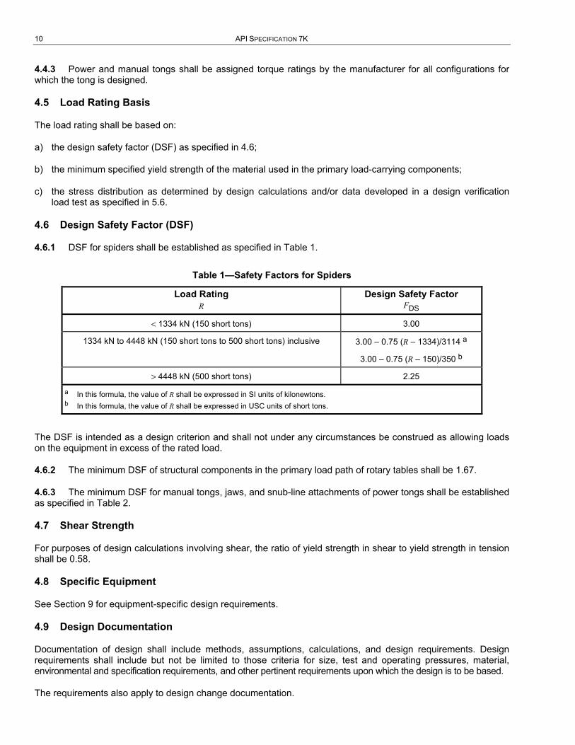
4.6.1 DSF for spiders shall be established as specified in Table 1.
Table 1—Safety Factors for Spiders
Load Rating R
Design Safety Factor FDS
< 1334 kN (150 short tons) 3.00
1334 kN to 4448 kN (150 short tons to 500 short tons) inclusive 3.00 – 0.75 (R – 1334)/3114 a
3.00 – 0.75 (R – 150)/350 b
> 4448 kN (500 short tons) 2.25
a In this formula, the value of R shall be expressed in SI units of kilonewtons. b In this formula, the value of R shall be expressed in USC units of short tons.
The DSF is intended as a design criterion and shall not under any circumstances be construed as allowing loads on the equipment in excess of the rated load.
4.6.2 The minimum DSF of structural components in the primary load path of rotary tables shall be 1.67.
4.6.3 The minimum DSF for manual tongs, jaws, and snub-line attachments of power tongs shall be established as specified in Table 2.
4.7 Shear Strength
For purposes of design calculations involving shear, the ratio of yield strength in shear to yield strength in tension shall be 0.58.
4.8 Specific Equipment
See Section 9 for equipment-specific design requirements.
4.9 Design Documentation
Documentation of design shall include methods, assumptions, calculations, and design requirements. Design requirements shall include but not be limited to those criteria for size, test and operating pressures, material, environmental and specification requirements, and other pertinent requirements upon which the design is to be based.
The requirements also apply to design change documentation.
DRILLING AND WELL SERVICING EQUIPMENT 11
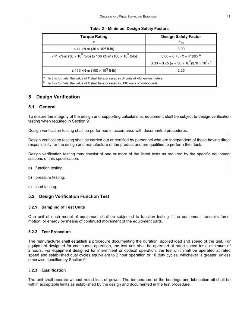
Table 2—Minimum Design Safety Factors
Torque Rating R
Design Safety Factor FDS
≤ 41 kN⋅m (30 × 103 ft-lb) 3.00
> 41 kN⋅m (30 × 103 ft-lb) to 136 kN⋅m (100 × 10
3 ft-lb) 3.00 – 0.75 (R – 41)/95 a
3.00 – 0.75 (R – 30 × 103)/(70 × 10
3) b
≥ 136 kN⋅m (100 × 103 ft-lb) 2.25
a In this formula, the value of R shall be expressed in SI units of kilonewton meters. b In this formula, the value of R shall be expressed in USC units of foot-pounds.
5 Design Verification
5.1 General
To ensure the integrity of the design and supporting calculations, equipment shall be subject to design verification testing when required in Section 9.
Design verification testing shall be performed in accordance with documented procedures.
Design verification testing shall be carried out or certified by personnel who are independent of those having direct responsibility for the design and manufacture of the product and are qualified to perform their task.
Design verification testing may consist of one or more of the listed tests as required by the specific equipment sections of this specification:
a) function testing;
b) pressure testing;
c) load testing.
5.2 Design Verification Function Test
5.2.1 Sampling of Test Units
One unit of each model of equipment shall be subjected to function testing if the equipment transmits force, motion, or energy by means of continued movement of the equipment parts.
5.2.2 Test Procedure
The manufacturer shall establish a procedure documenting the duration, applied load and speed of the test. For equipment designed for continuous operation, the test unit shall be operated at rated speed for a minimum of 2 hours. For equipment designed for intermittent or cyclical operation, the test unit shall be operated at rated speed and established duty cycles equivalent to 2 hour operation or 10 duty cycles, whichever is greater, unless otherwise specified by Section 9.
5.2.3 Qualification
The unit shall operate without noted loss of power. The temperature of the bearings and lubrication oil shall be within acceptable limits as established by the design and documented in the test procedure.
--``,``,```,,`````,`,,`,`,``,,`,-`-`,,`,,`,`,,`---
12 API SPECIFICATION 7K
5.3 Design Verification Pressure Test
5.3.1 Sampling of Test Units
Each design of pressure-containing items or, as defined in Section 9, primary load-carrying components, where the primary load is pressure, shall be hydrostatically tested for design verification. Hydraulic power transmission components are excluded from this test.
5.3.2 Test Procedure
The test pressure shall be 1.5 times the maximum rated operating pressure. Cold water, water with additives, or the fluid normally used in actual service shall be used as the test fluid. Tests shall be performed on the completed part or assembly before painting.
The hydrostatic test shall be applied for two cycles. Each cycle shall consist of the following four steps:
a) the primary pressure-holding period;
b) the reduction of the test pressure to zero;
c) thorough drying of all external surfaces of the item being tested;
d) the secondary pressure-holding period.
The pressure-holding periods shall not start until the test pressure has been reached, and the equipment and pressure-monitoring gauge isolated from the pressure source. The pressure-holding periods shall not be less than 3 minutes.
5.3.3 Qualification
After each test cycle, the test item shall be carefully inspected for the absence of leakage or permanent deformation. Failure to meet this requirement, or premature failure, shall be the cause for a complete reassessment of the design, followed by repetition of the test.
5.3.4 Individual Parts
Individual parts of the unit may be tested separately if the test fixture duplicates the loading conditions applicable to the part in the assembled unit.
5.4 Design Verification Load Test
5.4.1 General
When required by the specific equipment paragraphs of Section 9, equipment shall be subjected to a design verification load test.
5.4.2 Sampling of Test Units
To qualify design stress calculations applied to a family of units with an identical design concept but of varying sizes and ratings, one of the following options shall apply.
a) A minimum of three units of the design shall be subjected to design verification load testing. The test units shall be selected from the lower end, middle, and upper end of the load rating range.
b) Alternatively, the required number of test units can be established on the basis that each test unit also qualifies one load rating above and one below that of the selected test unit. (This option would generally apply to limited product rating ranges.)
--``,``,```,,`````,`,,`,`,``,,`,-`-`,,`,,`,`,,`---
DRILLING AND WELL SERVICING EQUIPMENT 13
5.4.3 Test Procedure
The test procedure is as follows.
a) An assembled test unit shall be loaded to the maximum rated load. After this load has been released, the unit shall be checked for its intended design functions. The function of all of the equipment parts shall not be impaired by this loading.
b) Strain gauges shall be applied to the test unit at all places where high stresses are anticipated, provided that the configuration of the unit permits such techniques. The use of finite-element analysis, models, brittle lacquer, and so forth, is recommended to confirm the proper location of the strain gauges. Three-element strain gauges are recommended in critical areas to permit determination of the shear stresses and to eliminate the need for exact orientation of the gauges.
c) The design verification test load to be applied to the test unit shall be determined as follows:
Design verification test load = 0.8 × R × FDS, but not less than 2R (3)
where
R is the load rating in kilonewtons (short tons) or kilonewton meters (foot-pounds), as applicable;
FDS is the design safety factor as defined in 3.1.5 and 4.6.
d) The test unit shall be loaded to the design verification test load. This test load should be applied incrementally, reading the strain gauge values and observing for evidence of yielding. The test unit may be loaded as many times as necessary to obtain adequate data.
e) The stress values computed from the strain gauge readings shall not exceed the values obtained from design calculations (based on the design verification test load) by more than the uncertainty of the testing apparatus specified in 5.7. Failure to meet this requirement, or premature failure of any test unit, shall be a cause for complete reassessment of the design, followed by additional testing of an identical number of test units as originally required, including a test unit of the same load rating as the one that failed.
f) Upon completion of the design verification load test, the test unit shall be disassembled and the dimensions of each primary load-carrying component checked for evidence of permanent deformation.
g) Individual parts of a test unit may be load-tested separately if the holding fixtures duplicate the loading conditions applicable to the part in the assembled unit.
5.5 Determination of Rated Load
The rated load shall be determined from the results of the design verification load test and/or stress distribution calculations required by Section 4. The stresses at that rating shall not exceed the maximum allowable stress. Localized yielding shall be permitted at areas of contact. In a unit that has been design verification load-tested, the critical permanent deformation determined by strain gauges or other suitable means shall not exceed 0.2 % except in contact areas. If the stresses exceed the allowable values, the affected part or parts shall be redesigned to obtain the desired rating. Stress distribution calculations may be used to load-rate the equipment only if the stress values determined in the analysis are no less than the stresses observed during the design verification load test.
5.6 Alternative Design Verification Test Procedure and Rating
Destructive testing of the test unit may be used, provided the yield and tensile strengths of the material used in the equipment have been determined. This may be accomplished using tensile test specimens from the same heat and heat-treatment lot as the parts represented, and meeting the requirements of ISO 6892 or ASTM A370.
Each component of an assembly shall be qualified under the most unfavorable loading configuration. Components may be qualified using either of the following methods.
--``,``,```,,`````,`,,`,`,``,,`,-`-`,,`,,`,`,,`---
14 API SPECIFICATION 7K
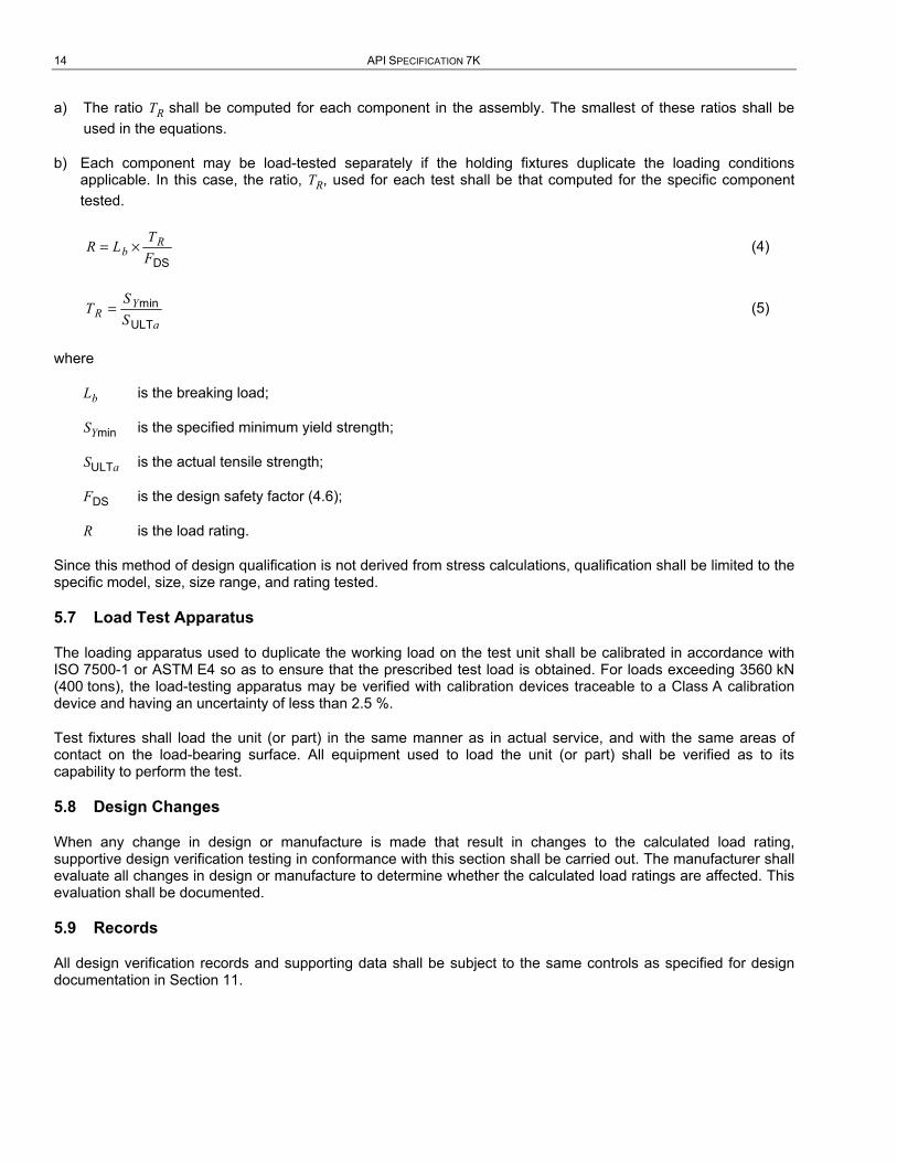
a) The ratio TR shall be computed for each component in the assembly. The smallest of these ratios shall be used in the equations.
b) Each component may be load-tested separately if the holding fixtures duplicate the loading conditions applicable. In this case, the ratio, TR, used for each test shall be that computed for the specific component tested.
DS
Rb
TR L
F= × (4)
YR
a
ST
S= min
ULT (5)
where
Lb is the breaking load;
SYmin is the specified minimum yield strength;
SULTa is the actual tensile strength;
FDS is the design safety factor (4.6);
R is the load rating.
Since this method of design qualification is not derived from stress calculations, qualification shall be limited to the specific model, size, size range, and rating tested.
5.7 Load Test Apparatus
The loading apparatus used to duplicate the working load on the test unit shall be calibrated in accordance with ISO 7500-1 or ASTM E4 so as to ensure that the prescribed test load is obtained. For loads exceeding 3560 kN (400 tons), the load-testing apparatus may be verified with calibration devices traceable to a Class A calibration device and having an uncertainty of less than 2.5 %.
Test fixtures shall load the unit (or part) in the same manner as in actual service, and with the same areas of contact on the load-bearing surface. All equipment used to load the unit (or part) shall be verified as to its capability to perform the test.
5.8 Design Changes
When any change in design or manufacture is made that result in changes to the calculated load rating, supportive design verification testing in conformance with this section shall be carried out. The manufacturer shall evaluate all changes in design or manufacture to determine whether the calculated load ratings are affected. This evaluation shall be documented.
5.9 Records
All design verification records and supporting data shall be subject to the same controls as specified for design documentation in Section 11.

DRILLING AND WELL SERVICING EQUIPMENT 15
6 Materials Requirements
6.1 General
This section describes the various material qualification, property, and processing requirements for primary load-carrying and pressure-containing components unless otherwise specified.
6.2 Written Specifications
Materials used in the manufacture of primary load-carrying components of equipment to which this specification is applicable shall conform to a written specification that meets or exceeds the design requirements.
6.3 Mechanical Properties
6.3.1 Impact Toughness
Impact testing shall be in accordance with ISO 148 (V-notch Charpy) or ASTM A370 (V-notch Charpy).
When it is necessary for subsize impact test pieces to be used, the acceptance criteria shall be multiplied by the appropriate adjustment factor listed in Table 3. Subsize test pieces of width less than 5 mm (3/16 in.) are not permitted.
For design temperatures below those specified in 4.1, supplementary impact toughness requirements may apply. See Annex A, Supplementary Requirements SR2 and SR2A.
Table 3—Adjustment Factors for Subsize Impact Specimens
Specimen Dimensions mm × mm
Adjustment Factor
10.0 × 7.5 0.833
10.0 × 5.0 0.667
6.3.2 Through-thickness Properties
Where the design requires through-thickness properties, materials shall be tested for reduction of area in the through-thickness direction in accordance with ASTM A770. The minimum reduction shall be 25 %.
6.4 Material Qualification
6.4.1 The mechanical tests required by this specification shall be performed on qualification test coupons representing the heat and heat-treatment lot used in the manufacture of the component. Tests shall be performed in accordance with the requirements of ISO 6892, ISO 148 or ASTM A370, or equivalent national standards, using material in the final heat-treated condition. For the purposes of material qualification testing, stress relief following welding is not considered heat treatment, provided that the PWHT temperature is below that which changes the heat-treated condition of the base material. Material qualification tests may be performed before the stress-relieving process, provided that the stress-relieving temperature is below that which changes the heat-treatment condition.
6.4.2 Determine the size of the qualification test coupon for a part using the equivalent-round method. Figure 1 and Figure 2 illustrate the basic models for determining the equivalent round (ER) of simple solid and hollow parts. Any of the shapes shown may be used for the qualification test coupon. Figure 3 describes the steps for determining the governing equivalent-round for more complex sections. Determine the ER of a part using the actual dimensions of the part in the “as-heat-treated” condition. The ER of the qualification test coupon shall be equal to or greater than the equivalent-round dimensions of the part it qualifies, except that the ER is not required to exceed 125 mm (5 in.). Figure 4 and Figure 5 illustrate the procedure for determining the required dimensions of an ASTM A370 keel block.
16 API SPECIFICATION 7K
6.4.3 Qualification test coupons shall either be integral with the components they represent, or be separate from the components, or be taken from sacrificed production part(s). In all cases, test coupons shall be from the same heat as the components they qualify, shall be subjected to the same working operations and shall be heat treated together with the components.
6.4.4 Test specimens shall be removed from integral or separate qualification test coupons so that their longitudinal centerline axis is entirely within the center core 1/4-thickness envelope for a solid test coupon, or within 3 mm (1/8 in.) of the mid-thickness of the thickest section of a hollow test coupon. The gauge length of a tensile specimen or the notch of an impact specimen shall be at least 1/4-thickness from the ends of the test coupon.
6.4.5 Test specimens taken from sacrificed production parts shall be removed from the center core 1/4-thickness envelope location of the thickest section of the part.
6.4.6 For components to be machined entirely from wrought material which has been fully heat treated as a solid or tubular bar, whereby the standard 1/4T envelope is either wholly or partly outside the volume of the critical and/or non-critical areas of the finished component, the test specimens, cut from the bar, may alternatively be taken from a more representative volume as defined by:
a) volume OD defined by a 1/3T envelope determined by using the maximum finished OD and the minimum finished ID of the final component;
b) the volume ID shall be equal to, or greater than, the minimum finished ID of the component.
EXAMPLE
6 in. OD 4340 mod bar, non-quenched tempered (NQT);
part final dimensions have maximum OD of 5.5 in., minimum ID of 2.5 in.;
T = (5.5 – 2.5)/2 = 1.5 in. 1/3T = 0.5 in.
The 1/3T envelope of the finished part would have a 4.5 in. OD;
therefore, the specimens could be removed from anywhere within the volume defined by 4.5 in. OD × 2.5 in. ID; (the 1/3T outer envelope and the finished ID of the component).
6.5 Manufacture
6.5.1 The manufacturing processes shall ensure repeatability in producing components that meet all the requirements of this specification.
6.5.2 All wrought materials shall be manufactured using processes that produce a wrought structure throughout the component.
6.5.3 All heat-treatment operations shall be performed utilizing equipment qualified in accordance with the requirements specified by the manufacturer or processor. The loading of the material within heat-treatment furnaces shall be such that the presence of any one part does not adversely affect the heat-treating response of any other part within the heat-treatment lot. The temperature and time requirements for heat-treatment cycles shall be determined in accordance with the manufacturer’s or processor’s written specification. Actual heat-treatment temperatures and times shall be recorded, and heat-treatment records shall be traceable to relevant components.
NOTE See Annex B for recommendations on qualification of heat-treating equipment.

DRILLING AND WELL SERVICING EQUIPMENT 17
6.6 Chemical Composition
The material composition of each heat shall be analyzed in accordance with the requirements of ASTM A751 (see ISO TR 9769 for further information), or equivalent national standard, for all elements specified in the manufacturer’s written material specification.
ER = t a) Round
ER = 1.1t b) Hexagon
ER = 1.25t c) Square
ER = 1.5t d) Rectangle or Plate
NOTE When L is < t, consider section as a plate of thickness L.
Figure 1—Equivalent Round (ER) Models—Solids of Length L
a) Open Both Ends a
ER = 2t
b) Restricted or Closed at One or Both Ends b
ER = 2.5t when D is ≤ 63.5 mm (2.5 in.).
ER = 3.5t when D is > 63.5 mm (2.5 in.).
a When L is < D, consider as a plate of thickness t. When L is < t, consider as a plate of L thickness. b Use maximum thickness, t, in the calculation.
Figure 2—Equivalent Round (ER) Models—Tube (Any Section)
--``,``,```,,`````,`,,`,`,``,,`,-`-`,,`,,`,`,,`---
18 API SPECIFICATION 7K
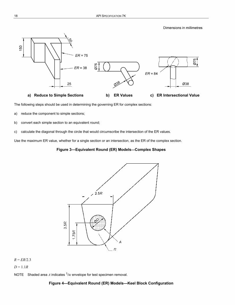
a) Reduce to Simple Sections b) ER Values c) ER Intersectional Value
The following steps should be used in determining the governing ER for complex sections:
a) reduce the component to simple sections;
b) convert each simple section to an equivalent round;
c) calculate the diagonal through the circle that would circumscribe the intersection of the ER values.
Use the maximum ER value, whether for a single section or an intersection, as the ER of the complex section.
Figure 3—Equivalent Round (ER) Models—Complex Shapes
R = ER/2.3
D = 1.1R
NOTE Shaded area A indicates 1/4t envelope for test specimen removal.
Figure 4—Equivalent Round (ER) Models—Keel Block Configuration

DRILLING AND WELL SERVICING EQUIPMENT 19
To develop a keel block for ER = 115 mm:
a) noting from Figure 5 that R = ER/2.3 = 50 mm and D = 1.1R,
b) construct a keel block as illustrated in Figure 3 using multiples of R.
a R = ER/2.3 = 50 mm. b Keel block dimensions. c Diameter D.
Figure 5—Development of Keel Block Dimensions
7 Welding Requirements
7.1 General
This section describes requirements for the fabrication and repair welding of primary load-carrying and pressure-containing components, including attachment welds.
7.2 Welding Qualification
All welding undertaken on components shall be performed using welding procedures that are qualified in accordance with ASME BPVC, Section IX, AWS D1.1, and/or ASTM A488. This welding shall only be carried out by welders or welding operators who are qualified in accordance with the aforementioned standards or BS EN 287.
Welding procedures for base materials that are not listed in the above standards shall be qualified individually or as a group based on weldability, tensile properties, or composition. Where the ductility of the parent metal is such as to render it incapable of meeting the bend test requirements of ASME BPVC, Section IX, the bend test shall be conducted in the following manner: a bend bar comprised of parent metal heat treated to the ductility and strength requirements of the applicable specification shall be bent to failure. The side bend specimen taken from the weld test coupon shall then be capable of being bent to within 5° of the angle thus determined.
--``,``,```,,`````,`,,`,`,``,,`,-`-`,,`,,`,`,,`---
20 API SPECIFICATION 7K
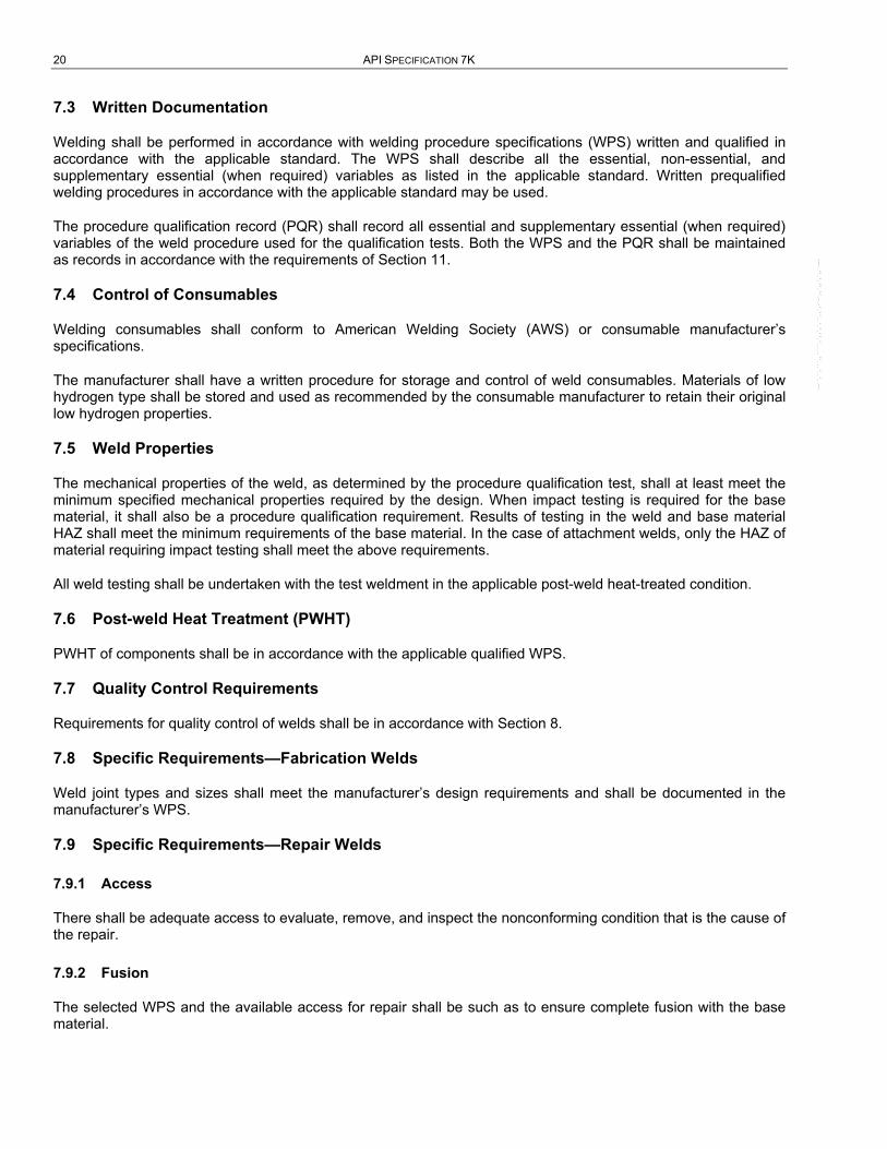
7.3 Written Documentation
Welding shall be performed in accordance with welding procedure specifications (WPS) written and qualified in accordance with the applicable standard. The WPS shall describe all the essential, non-essential, and supplementary essential (when required) variables as listed in the applicable standard. Written prequalified welding procedures in accordance with the applicable standard may be used.
The procedure qualification record (PQR) shall record all essential and supplementary essential (when required) variables of the weld procedure used for the qualification tests. Both the WPS and the PQR shall be maintained as records in accordance with the requirements of Section 11.
7.4 Control of Consumables
Welding consumables shall conform to American Welding Society (AWS) or consumable manufacturer’s specifications.
The manufacturer shall have a written procedure for storage and control of weld consumables. Materials of low hydrogen type shall be stored and used as recommended by the consumable manufacturer to retain their original low hydrogen properties.
7.5 Weld Properties
The mechanical properties of the weld, as determined by the procedure qualification test, shall at least meet the minimum specified mechanical properties required by the design. When impact testing is required for the base material, it shall also be a procedure qualification requirement. Results of testing in the weld and base material HAZ shall meet the minimum requirements of the base material. In the case of attachment welds, only the HAZ of material requiring impact testing shall meet the above requirements.
All weld testing shall be undertaken with the test weldment in the applicable post-weld heat-treated condition.
7.6 Post-weld Heat Treatment (PWHT)
PWHT of components shall be in accordance with the applicable qualified WPS.
7.7 Quality Control Requirements
Requirements for quality control of welds shall be in accordance with Section 8.
7.8 Specific Requirements—Fabrication Welds
Weld joint types and sizes shall meet the manufacturer’s design requirements and shall be documented in the manufacturer’s WPS.
7.9 Specific Requirements—Repair Welds
7.9.1 Access
There shall be adequate access to evaluate, remove, and inspect the nonconforming condition that is the cause of the repair.
7.9.2 Fusion
The selected WPS and the available access for repair shall be such as to ensure complete fusion with the base material.
--``,``,```,,`````,`,,`,`,``,,`,-`-`,,`,,`,`,,`---
DRILLING AND WELL SERVICING EQUIPMENT 21
7.9.3 Forgings and Castings
All repair welding shall be performed in accordance with the manufacturer’s written welding specifications. WPSs shall be documented and shall be supplied at the purchaser’s request.
The manufacturer shall document the following criteria for permitted repairs:
⎯ defect type;
⎯ defect size limits;
⎯ definition of major/minor repairs.
All excavations, prior to repair, and the subsequent weld repair shall meet the quality control requirements specified in Section 8.
7.9.4 Heat Treatment
The WPS used for qualifying a repair shall reflect the actual sequence of weld repair and heat treatment imparted to the repair item.
8 Quality Control
8.1 General
This section specifies the quality control requirements for equipment and material. All quality control work shall be controlled by the manufacturer’s documented instructions, which shall include appropriate methodology, quantitative and qualitative acceptance criteria.
Instructions for NDE activities shall be sufficiently detailed regarding the requirements of this specification and those of all applicable referenced specifications. All NDE instructions shall be approved by an examiner qualified to an ASNT SNT-TC-1A, Level III examiner.
The acceptance status of all equipment, parts, and materials shall be indicated either on the equipment, parts, or materials or in the records traceable to the equipment, parts, or materials.
8.2 Quality Control Personnel Qualifications
NDE personnel shall be qualified and/or certified in accordance with ASNT SNT-TC-1A.
Personnel performing visual inspection of welding operations and completed welds shall be qualified in accordance with:
⎯ AWS QC1 or equivalent standard; or
⎯ the manufacturer’s documented training program (to be equivalent to above).
All personnel performing other quality control activities directly affecting material and product quality shall be qualified in accordance with the manufacturer’s documented procedures.
8.3 Measuring and Test Equipment
Equipment used to inspect, test, or examine material or other equipment shall be identified, controlled, calibrated, and adjusted at specified intervals in accordance with documented manufacturer instructions, and consistent with a recognized industry standard (e.g. ISO 10012-1 [2], MIL STD 120 [10]), to maintain the required level of accuracy.
22 API SPECIFICATION 7K
8.4 Quality Control for Specific Equipment and Components
8.4.1 General
The quality control requirements shall apply to all primary load-bearing and/or pressure-containing equipment and components unless specified otherwise.
The manufacturer shall establish and maintain critical area drawings identifying high stress areas, which shall be used in conjunction with this section.
For purposes of this section, critical areas shall be defined as all areas where the stress in the component is:
0.75 min
DS
YSF
≥ (6)
where
SYmin is the specified minimum yield strength;
FDS is the design safety factor.
If critical areas are not identified on critical area drawings, then all surfaces of the component shall be considered critical.
Areas of components in which the stress is compressive, and/or where the stress level is:
0.1 min
DS
YSF
≤ (7)
where
SYmin is the specified minimum yield strength;
FDS is the design safety factor;
shall be exempt from the acceptance criteria defined in 8.4.7.4. The low stress areas thus defined may be identified on the critical area map.
8.4.2 Chemical Analysis
Methods and acceptance criteria shall be in accordance with 6.6.
8.4.3 Tensile Testing
Methods and acceptance criteria shall be in accordance with 6.3 and 6.4.
8.4.4 Impact Testing
Methods and acceptance criteria shall be in accordance with 6.3 and 6.4.
8.4.5 Traceability
Components shall be traceable by heat, and heat-treatment lot, identification.
Identification shall be maintained on materials and components through all stages of manufacturing and on the finished components or assembly. Manufacturer’s documented traceability requirements shall include provisions
--``,``,```,,`````,`,,`,`,``,,`,-`-`,,`,,`,`,,`---
DRILLING AND WELL SERVICING EQUIPMENT 23
for maintenance and replacement of identification marks and identification control records. Fasteners and pipe fittings shall be exempt from the traceability requirements, provided they are marked in accordance with a recognized industry standard.
8.4.6 Visual Examination
Components shall be visually examined. Visual examination of castings shall meet the requirements of MSS SP-55. Examination of wrought material shall be in accordance with the manufacturer’s documented procedures.
8.4.7 Surface NDE
8.4.7.1 General
All accessible surfaces of each finished component shall be inspected in accordance with 8.4.7 after final heat treatment and final machining operations.
If the equipment is subjected to a load test, the qualifying NDE shall be carried out after the load test. For materials susceptible to delayed cracking, as identified by the manufacturer, NDE shall be carried out no earlier than 24 hours after the load test. The equipment shall be disassembled for this inspection. Conducting surface coatings shall be removed prior to examination. Non-conducting surface coatings shall be removed prior to examination unless it has been demonstrated that the smallest relevant indications, as defined in 8.4.7.3, can be detected through the maximum applied thickness of the coating.
8.4.7.2 Method
Ferromagnetic materials shall be examined by the magnetic particle method in accordance with ASME BPVC, Section V, Subsection A, Article 7, and Subsection B, Article 25, or ASTM E709. Machined surfaces shall be examined by the wet fluorescent method; other surfaces shall be examined by a wet method or dry method.
Non-ferromagnetic materials shall be examined by the liquid penetrant method in accordance with ASME BPVC, Section V, Subsection A, Article 6, and Subsection B, Article 24, or ASTM E165.
The use of prods should be avoided if possible. If prods are used, all prod burn marks shall be removed by grinding and the affected areas re-examined by the liquid penetrant method.
8.4.7.3 Evaluation of Indications
Only those indications with major dimensions greater than 2 mm (1/16 in.) and associated with a surface rupture shall be considered relevant. Inherent indications not associated with a surface rupture (i.e. magnetic permeability variations, non-metallic stringers, etc.) shall be considered non-relevant. If magnetic particle indications greater than 2 mm (1/16 in.) are believed to be non-relevant, they shall either be examined by the liquid penetrant method to confirm they are non-relevant, or they shall be removed and re-inspected to confirm they are non-relevant.
Relevant indications shall be evaluated in accordance with the acceptance criteria specified in 8.4.7.4.
8.4.7.4 Acceptance Criteria
8.4.7.4.1 Castings
ASTM E125 shall be applied as a reference standard for the evaluation of magnetic particle indications on castings. The acceptance criteria shall be as specified in Table 4.

24 API SPECIFICATION 7K
Table 4—Castings Indication Acceptance Criteria
Type Discontinuity Descriptions Maximum Permitted Degree
Critical Areas Non-critical Areas
I Hot tears, cracks None Degree 1
II Shrinkage Degree 2 Degree 2
III Inclusions Degree 2 Degree 2
IV Internal chills, chaplets Degree 1 Degree 1
V Porosity Degree 1 Degree 2
8.4.7.4.2 Wrought Materials
The following acceptance criteria shall apply for surface NDE of wrought materials:
⎯ no relevant indications with a major dimension equal to or greater than 5 mm (3/16 in.);
⎯ no more than 10 relevant indications in any continuous 40 cm2 (6 in.2) area;
⎯ no more than three relevant indications in a line separated by less than 2 mm (1/16 in.) edge-to-edge;
⎯ no relevant indications in pressure-sealing areas, in the root area of rotary threads or in the stress-relief features of threaded joints.
8.4.8 Volumetric NDE of Castings
8.4.8.1 Method
Radiographic examination of castings shall be in accordance with ASME BPVC, Section V, Subsection A, Article 2, and Subsection B, Article 22 with the restriction that fluorescent intensifying screens shall not be used.
Ultrasonic examination shall be in accordance with ASME BPVC, Section V, Subsection A, Article 5, and Subsection B, Article 23. The component(s) shall be examined by the straight-beam method in accordance with SA-609 of Article 23 and shall be supplemented by angle beam examination as in T-534.2 of Article 5 in areas where a back reflection cannot be maintained during the straight-beam examination, or where the angle between the two surfaces of the component is more than 15°.
8.4.8.2 Sampling
Primary-load-carrying castings shall be examined by volumetric NDE on the following sampling basis as a minimum:
⎯ all areas of initial or prototype castings shall be examined by ultrasonic or radiographic methods until the results of such examination indicate that a satisfactory production technique has been established;
⎯ thereafter, one casting out of each production lot or, for production lots of less than ten castings, one out of every ten production castings, shall be volumetrically examined in all critical areas as identified on critical area drawings. If any casting shows any indications outside the acceptance criteria defined in 8.4.8.3, two more castings from that production lot shall be examined by the same method. If the two additional castings are acceptable, the remainder of the batch may be accepted and the initial non-conforming casting shall be repaired or scrapped.
DRILLING AND WELL SERVICING EQUIPMENT 25
8.4.8.3 Acceptance Criteria
8.4.8.3.1 General
Areas of components where the stress level is less than the value of low stress [as calculated in Equation (7)] shall be exempt from volumetric examination.
8.4.8.3.2 Radiography
The acceptance criteria for radiographic examination are based on the Standard Reference Radiographs of ASTM E446, ASTM E186, or ASTM E280 depending on the wall thickness being examined.
In all cases, cracks, hot tears and inserts (defect types D, E and F, respectively) are not permitted.
The remaining indication types shown in the reference radiographs shall meet Severity Level 2 in all critical areas and Severity Level 3 in non-critical areas. Critical areas shall be as defined in 8.4.1. If critical areas are not identified on critical-area drawings, then all areas of the component shall be considered critical.
8.4.8.3.3 Ultrasonic Examination
The acceptance criteria for both straight-beam and angle-beam ultrasonic examination of castings are based on SA-609 in ASME BPVC, Section V, Subsection B, Article 23, Quality Level 3, with the exception that Quality Level 1 shall apply within 50 mm (2 in.) of the casting surface. Discontinuities indicated as having a change in depth of 25 mm (1 in.) or half the thickness, whichever is the lesser, are not permitted.
8.4.9 NDE of Welds
8.4.9.1 General
If examination is required, essential welding variables and equipment shall be monitored during welding. The entire accessible weld, plus at least 13 mm (1/2 in.) of surrounding base metal, shall be examined in accordance with the methods and acceptance criteria of 8.4.9.
The NDE required under 8.4.9 shall be carried out after final heat treatment.
8.4.9.2 Fabrication Welding
8.4.9.2.1 Visual Examination
All fabrication welds shall be visually examined in accordance with ASME BPVC, Section V, Subsection A, Article 9. Undercuts shall not reduce the thickness in the affected area to below the design thickness, and shall be ground to blend smoothly with the surrounding material.
Surface porosity or exposed slag are not permitted on, or within 3 mm (1/8 in.) of, sealing surfaces.
8.4.9.2.2 Surface NDE
All primary load-carrying and pressure-containing welds and attachment welds to primary load-carrying and pressure-containing components shall be examined as specified in 8.4.7.2.
The following acceptance criteria shall apply:
⎯ no relevant linear indications (see 3.1.22);
⎯ no rounded indications (see 3.1.36) with a major dimension greater than 4 mm (1/8 in.), for welds whose depth is 17 mm (5/8 in.) or less;
--``,``,```,,`````,`,,`,`,``,,`,-`-`,,`,,`,`,,`---

26 API SPECIFICATION 7K
⎯ no rounded indications with a major dimension greater than 5 mm (3/16 in.) for welds whose depth is greater than 17 mm (5/8 in.);
⎯ no more than three relevant indications in a line separated by less than 2 mm (1/16 in.) edge-to-edge.
8.4.9.2.3 Volumetric NDE
Primary load-bearing and pressure-containing welds shall be examined by either ultrasonic or radiographic methods. Ultrasonic examination shall be in accordance with ASME BPVC, Section V, Subsection A, Article 5, and radiographic examination shall be in accordance with ASME BPVC, Section V, Subsection A, Article 2. This applies to full-penetration welds only.
Acceptance criteria shall be in accordance with the requirements of ASME BPVC, Section VIII, Division 1, UW-51 and Appendix 12, as appropriate.
8.4.9.3 Repair Welds
8.4.9.3.1 Weld Excavations
Magnetic particle examination shall be performed on all excavations for weld repairs, with the method and acceptance criteria as specified in 8.4.7.
8.4.9.3.2 Repair Welds in Castings
All repair welds in castings shall be examined in accordance with 8.4.7.2. Acceptance criteria shall be identical to those for fabrication welds (see 8.4.9.2).
8.4.9.3.3 Repair of Welds
NDE of the repairs of weld defects shall be identical to that of the original weld (see 8.4.9.2).
8.5 Dimensional Verification
Verification of dimensions shall be carried out on a sample basis as defined and documented by the manufacturer.
All main load-bearing and pressure-sealing threads shall be gauged to the requirements of the relevant thread specification(s).
8.6 Proof Load Testing
When proof load testing is required, as indicated under the relevant equipment headings of Section 9, the following requirements shall apply.
a) Each production unit or primary load-carrying component shall be load-tested in accordance with the requirements of this section.
b) The equipment shall be mounted in a test fixture capable of loading the equipment in the same manner as in actual service and with the same areas of contact on the load-bearing surfaces. Rolling-element bearings that would be damaged by the test may be replaced by a load transfer device.
c) A test load equal to 1.5 times the rated load shall be applied and held for a period of not less than 5 minutes.
d) Following the load test, the design functions of the equipment shall be checked, as applicable. Proper functioning of the equipment shall not be impaired by the load test.
e) Assembled equipment shall be subsequently stripped down to a level that will permit full surface NDE of all primary load-bearing parts (excluding bearings).
--``,``,```,,`````,`,,`,`,``,,`,-`-`,,`,,`,`,,`---

DRILLING AND WELL SERVICING EQUIPMENT 27
f) All critical areas of the primary load-bearing parts shall be subjected to magnetic particle examination in conformance with 8.4.7.
Equipment normally exempt from load testing shall be given a proof load test if supplementary requirement SR1 (see Annex A) is specified in the order.
8.7 Hydrostatic Testing
8.7.1 General
When hydrostatic testing is required, as indicated under the relevant equipment headings of Section 9, the requirements of 8.7 shall apply.
8.7.2 Test Sequence
The hydrostatic test shall be carried out in three steps:
a) the primary pressure-holding period;
b) the reduction of the pressure to zero;
c) the secondary pressure-holding period.
Both pressure-holding periods shall not be less than 3 minutes, the timing of which shall not start until the test pressure has been reached, the equipment and the pressure-monitoring gauge have been isolated from the pressure source, and the external surfaces of the body members have been thoroughly dried.
Specific hydrostatic testing requirements are included under the relevant equipment headings of Section 9.
8.7.3 Calibrated Pressure Gauges
Calibrated pressure gauges and recording equipment shall be used during testing. Recorder graphs shall be signed, dated, and made traceable to the equipment being tested.
8.8 Functional Testing
Specific functional testing requirements are included under the relevant equipment headings of Section 9.
9 Equipment
9.1 General
The requirements of Section 4 through Section 8 apply to the primary load-carrying components of the covered equipment unless specifically noted otherwise. It is the equipment designer’s responsibility to determine the primary load path through the equipment and to define primary load-carrying components.
Slip inserts and tong dies are exempt from testing, NDE, and traceability requirements of 6.3, 6.4, 6.5, 8.4, and 8.6.
9.2 Rotary Tables
9.2.1 General
The requirements of 4.2.7, 5.4, 5.5, 5.6, 6.3.1, 8.4.4, 8.4.5, 8.4.7, 8.4.8, and 8.6 shall not apply. For antifriction bearing design and manufacturing requirements, see 9.19.

28 API SPECIFICATION 7K
9.2.2 Primary Load
The primary load is the axial load through the center of the rotary table. Rotary torque is not taken as a primary load.
9.2.3 Design Verification Function Test
Design verification function test, as described in 5.2, shall apply.
9.2.4 Static Load Rating
The static load rating, or primary load rating, for a rotary table shall be equal to or less than the static load capacity of the main bearing.
9.2.5 Rotary Table Pinion-shaft Extension
Rotary tables, with straight pinion-shaft extensions, shall be furnished in the sizes shown in Table 5 and shall conform to the dimensions and tolerances shown in Table 5 and Figure 6. This section does not preclude alternative drive input configurations (e.g. other straight or tapered pinion-shaft extensions, hydraulics drives, etc.).
9.2.6 Drive Sprocket
The distance, L, between the center of the rotary table and the center of the first row of sprocket teeth (see Figure 7) shall be 1353 mm (53 1/4 in.) for machines that will pass a 510 mm (20 in.) bit or larger, and shall be 1118 mm (44 in.) for machines that will not pass a 510 mm (20 in.) bit, except that, by agreement between the manufacturer and purchaser, the distance of 1353 mm (53 1/4 in.) may be used on machines that will not pass a 510 mm (20 in.) bit. The distance, L, shall be either 1353 mm or 1651 mm (53 1/4 in. or 65 in.) for the 1257 mm (49 1/2 in.) nominal rotary table. The distance, L, shall be 1840 mm (72 in.) for the 60 1/2 in. nominal rotary table. These distances may be stamped on the nameplate (if used) attached to the rotary table.
Table 5—Rotary Table Pinion-straight Shaft Extension Dimensions in millimeters (inches)
Size No.
Diameter of Extension Keyway
Width Depth A B C
−00.025 ( )−
00.001 +0.025
0 ( )+0.0010 1,52
0+ ( )+0.060
0
1 82.55 (3.250) 19.05 (0.750) 6.35 (1/4)
2 100.03 (3.938) 25.40 (1.000) 9.52 (3/8)
3 107.95 (4.250) 25.40 (1.000) 9.52 (3/8)
4 114.30 (4.500) 25.40 (1.000) 9.52 (3/8)
5 125.43 (4.938) 31.75 (1.250) 11.11 (7/16)
NOTE See Figure 6 for illustration of dimension symbols.

DRILLING AND WELL SERVICING EQUIPMENT 29
Key 1 centerline of first row of teeth (Figure 7)
NOTE See Table 5 for dimensions.
a See Figure 7 and 9.2.6.
Figure 6—Rotary Table Pinion-straight Shaft Extension
9.2.7 Rotary Table Openings
Rotary tables for use with square-drive master bushings shall conform to the requirements of Table 6 and Figure 8. Rotary tables for use with the four-pin-drive master bushings shall conform to the requirements in Table 7 and Figure 9. This section does not preclude rotary tables of other nominal sizes.
9.2.8 Demountable Rotary Table Sprockets
Demountable rotary table sprockets are shown in Table 8 and Figure 10. The sprockets, both single-strand and double-strand, have a common bolt circle.
9.3 Rotary Bushings
9.3.1 General
Rotary bushings and bushing adapters are included for the purpose of dimensional interchangeability only, and load rating is not required. The requirements of 6.3.1, 8.4.5, 8.4.7, 8.4.8, and 8.4.9 shall not apply.
9.3.2 Kelly Bushings
Square-drive kelly bushing dimensions are shown in Figure 7.
Pin-drive kelly bushing dimensions are shown in Figure 9 and Table 7.
9.3.3 Master Bushing
Square-drive master bushings and rotary table square-drive master bushings shall conform to the requirements of Table 6 and Figure 8. Dimensions for four-pin-drive master bushings shall conform to the requirements in Table 7 and Figure 9.

30 API SPECIFICATION 7K
Dimensions in millimeters (inches)
Key 1 square-drive bushing removed from rotary table 2 pipe slips 3 kelly 4 cut-away showing master bushing
NOTE See 9.2.6 and 9.3.2 for description.
a (333.3 ± 1.5) mm/m [(4 ± 0.018) in./ft] taper on diameter.
Figure 7—Rotary Table with Square-drive Bushings
--``,``,```,,`````,`,,`,`,``,,`,-`-`,,`,,`,`,,`---

DRILLING AND WELL SERVICING EQUIPMENT 31
9.3.4 Bushing Adapters
Bushing adapters are used to reduce the openings of rotary tables so that a smaller-size master bushing may be used.
9.4 Standard Rotary Slips
9.4.1 Standard rotary slips shall have a taper of 33.33 mm/m (4 in./ft) and other suitable dimensions to permit operations in standard master bushings. Refer to 9.2.7 and Figure 7.
9.4.2 Load rating of standard rotary slips is not required.
9.4.3 The requirements of 8.4.4, 8.4.5, 8.4.8, and 8.4.9 shall not apply.
9.4.4 The requirements of 8.4.7 apply to API rotary slips, with the exception of the method and acceptance criteria of MSS SP-53 shall apply.
9.5 Nonstandard Rotary Slips
9.5.1 Nonstandard rotary slips without a taper of 33.333 cm/m (4 in./ft) shall have a taper to match the manual spider in which it is intended to be used, as defined in 1 i).
9.5.2 Load rating of nonstandard rotary slips is not required.
9.5.3 The requirements of 8.4.4, 8.4.5, 8.4.8, and 8.4.9 shall not apply.
9.5.4 The requirements of 8.4.7 apply to nonstandard rotary slips, with the exception of the method and acceptance criteria of MSS SP-53 shall apply.

32
AP
I SP
EC
IFIC
ATI
ON
7K
Tabl
e 6—
Rot
ary
Tabl
e O
peni
ng a
nd S
quar
e-dr
ive
Mas
ter B
ushi
ng
Dim
ensi
ons
in m
illim
eter
s (in
ches
)
Nom
inal
Tab
le
Size
Rot
ary
Tabl
e O
peni
ng
Squa
re-d
rive
Mas
ter B
ushi
ng
Con
cent
ricity
TI
R
A B
C D
A 1
B 1
C 1
D
1 +0
.38
0
()
+0.0
150
+0
.76
0
()
+0.0
300
max
. m
ax.
−0 0.38
(
)−0 0.
015
−0 0.76
(
)−0 0.
030
+6.3
50
(
)+0
.250
0
(17
1 /2)
44
4.5
444.
50
(17
1 /2)
46
1.96
(1
8 3 /
6)
133.
3 5
1 /4
44.4
5 (1
3 /4)
442.
91
(17
7 /16
)46
0.38
(1
8 1 /
8)
133.
35
(5 1 /
4)
44.4
5 (1
3 /4)
0.
79
(1 /32
)
(20
1 /2)
52
0.7
520.
70
(20
1 /2)
53
8.16
(2
1 3 /
16)
133.
3 5
1 /4
44.4
5 (1
3 /4)
519.
11
(20
7 /16
)53
6.58
(2
1 1 /
8)
133.
35
(5 1 /
4)
44.4
5 (1
3 /4)
0.
79
(1 /32
)
(27
1 /2)
69
8.5
698.
50
(27
1 /2)
71
5.96
(2
8 3 /
16)
133.
3 5
1 /4
44.4
5 (1
3 /4)
696.
91
(27
7 /16
)71
2.79
(2
8 1 /
16)
133.
35
(5 1 /
4)
44.4
5 (1
3 /4)
0.
79
(1 /32
)
(37
1 /2)
95
2.5
952.
50
(37
1 /2)
—
—
—
—
—
—
95
0.91
(3
7 7 /
16)
—
—
—
—
—
—
—
—
(49
1 /2)
12
57.3
1
257.
30
(49
1 /2)
—
—
—
—
—
—
—
—
—
—
—
—
—
—
—
—
(60
1 /2)
15
36.7
1
536.
70
(60
1 /2)
—
—
—
—
—
—
—
—
—
—
—
—
—
—
—
—
NO
TE
See
Fig
ure
7 an
d Fi
gure
8 fo
r illu
stra
tion
of s
ymbo
ls.
Tabl
e 7—
Four
-pin
-driv
e M
aste
r Bus
hing
and
Kel
ly B
ushi
ng
Dim
ensi
ons
in m
illim
eter
s (in
ches
)
Nom
inal
Tab
le S
ize
F G
H
I
J K
±1.5
9 (±
1 /16
) ±0
.13
(±0.
005)
±0
.13
(±0.
005)
+1
.59
0
()
1/16
0+
+1
.59
0
()
1/16
0+
(17
1 /2)
44
4.5
482.
60
(19)
65
.15
(2.5
65)
107.
95
(4 1
/4)
62.7
9 (2
.472
) 36
5.13
(1
4 3 /
8)
257.
18
(10
1 /8)
(20
1 /2)
52
0.7
584.
20
(23)
65
.15
(2.5
65)
107.
95
(4 1
/4)
62.7
9 (2
.472
) 36
5.13
(1
4 3 /
8)
257.
18
(10
1 /8)
(27
1 /2)
69
8.5
654.
05
(25
3 /4)
86
.23
(3.3
95)
107.
95
(4 1
/4)
82.9
3 (3
.265
) 36
5.13
(1
4 3 /
8)
257.
18
(10
1 /8)
(37
1 /2)
95
2.5
654.
05
(25
3 /4)
86
.23
(3.3
95)
107.
95
(4 1
/4)
82.9
3 (3
.265
) 36
5.13
(1
4 3 /
8)
257.
18
(10
1 /8)
(49
1 /2)
12
57.3
—
—
—
—
—
—
—
—
36
5.13
(1
4 3 /
8)
257.
18
(10
1 /8)
(60
1 /2)
15
36.7
—
—
—
—
—
—
—
—
36
5.13
(1
4 3 /
8)
257.
18
(10
1 /8)
NO
TE
See
Fig
ure
9 fo
r illu
stra
tion
of s
ymbo
ls.
--``,``,```,,`````,`,,`,`,``,,`,-`-`,,`,,`,`,,`---

DRILLING AND WELL SERVICING EQUIPMENT 33
Key 1 optional relief 2 relief
NOTE See 9.2.7, 9.3.3 and Table 6 for dimensions.
a Chamfer ≥ 6.35 mm (0.250 in.) × 45°. b ≤ 0.40 mm (0.016 in.) eccentricity. c (333.33 ± 1.5) mm/m [(4 ± 0.018) in./ft] taper on diameter (9°27'45 “± 2'30” taper per side).
Figure 8—Rotary Table Opening and Square-drive Master Bushing

34 API SPECIFICATION 7K
Key 1 pin-drive kelly bushing 2 pin-drive master bushing
NOTE See 9.2.7, 9.3.2, 9.3.3 and Table 6 and Table 7 for dimensions.
a (333.33 ± 1.5) mm/m [(4 ± 0.018) in./ft] taper on diameter (9°27'45 “± 2'30” taper per side). b Diameter of drive hole.
Figure 9—Pin-drive Master Bushing and Kelly Bushing
--``,``,```,,`````,`,,`,`,``,,`,-`-`,,`,,`,`,,`---

DRILLING AND WELL SERVICING EQUIPMENT 35
Key 1 hub 2 single sprocket 3 double sprocket
NOTE See 9.2.8 and Table 8 for dimensions.
a Maximum hub diameter to allow for chain clearance. b Chamfer 1.59 mm (0.063 in.) × 45°. c Eight holes equally spaced on 228.6 mm (9 in.) bolt circle diameter. d Applies to sprockets with minimum number of teeth. This can be increased for sprockets with more than the minimum
number of teeth to as much as the dimensions A minus B.
Figure 10—Demountable Rotary Sprocket
--``,``,```,,`````,`,,`,`,``,,`,-`-`,,`,,`,`,,`---

36 API SPECIFICATION 7K
Table 8—Demountable Rotary Sprocket Data
Sprocket Type Number of Teeth on
Sprocket min.
Sprocket Groove Diameter
max.
Sprocket Thickness at Groove
min. A B
mm (in.) mm (in.)
1 3/4 P single 23 — —
2 P single 21 — —
2 1/2 P single 17 — —
1 3/4 P double 25 306.39 (12 1/16) 10.32 (13/32)
2 P double 22 301.63 (11 7/8) 7.94 (5/16)
2 1/2 P double 19 315.91 (12 7/16) 15.08 (19/32)
NOTE See 9.2.6, 9.2.8 and Figure 10 for explanation and illustration of symbols.
9.6 High-pressure Mud and Cement Hoses
9.6.1 General
This specification applies to high-pressure flexible mud and cement hose assemblies as defined in 9.6.2.1 and listed in Table 9. This specification shall not apply to choke and kill flexible lines covered by API 16C. In addition, this specification shall not apply to flexible hoses or pipes for gas service, air drilling, and well completion or workover operations where it is intended or likely that hoses will be exposed to well bore effluents. Such hoses are covered by API 17B. See API 7L, Annex A, for information on operating limits, inspection, care, and use of cement hose, drilling mud vibrator and jumper hose, and rotary hose covered by this specification.
9.6.2 Exceptions to Requirements Specified in Section 1 Through Section 8
9.6.2.1 Definitions
Consistent with the definitions of the following terms specified in Section 3, the following clarifications are provided below as they shall apply to the hose assemblies covered by this specification:
a) the primary load shall be the internal pressure;
b) the primary load-carrying components shall be the reinforcing cables, wires, metal armors, and hose couplings;
c) the design load shall be the same as the working pressure of the hose assembly specified in Table 9;
d) the dynamic load shall be comprised of additional loads exerted on the hose assembly that are separate from that which is created by static pressure, such as pressure pulsations, and dynamic bending or flexing.
9.6.2.2 Design Conditions
Exceptions to the requirements specified in 4.1 are provided in the following.
a) The minimum operating temperature of hose assemblies covered by this specification is –4 °F (–20 °C).
b) With regard to the cautionary note in 4.1, operation of the hose assemblies covered by this specification at temperatures below the minimum specified is not recommended under any circumstances. In the event that the requirements of the purchase agreement dictate lower minimum operating temperatures than those specified above, the hose assembly shall be qualified by conducting a low-temperature bending test at the temperature specified in the purchase agreement in addition to those other tests that are required to establish the temperature range and FSL level specified in 9.6.3. In addition, when supplementary requirements SR2 and SR2A are specified in the purchase agreement, they shall only apply to the hose coupling.
--``,``,```,,`````,`,,`,`,``,,`,-`-`,,`,,`,`,,`---

DRILLING AND WELL SERVICING EQUIPMENT 37
Table 9—Rotary Drilling and Vibrator Hoses, Cement Hoses, Mud Delivery Hoses Dimensions and Pressures
Inside Diameter mm (in.)
API Grade
Working Pressure MPa (psi)
Test Pressure MPa (psi)
Safety Factor
Minimal Burst Pressure Mpa (psi)
MBR Operational a
m (in.)
Remark
50.8 (2.0)
A 10.3 (1500) 20.7 (3000) 2.50 25.8 (3750) 0.9 (36)
B 13.8 (2000) 27.6 (4000) 2.50 34.5 (5000) 0.9 (36)
C 27.6 (4000) 55.2 (8000) 2.50 69.0 (10,000) 0.9 (36)
D 34.5 (5000) 69.0 (10,000) 2.50 86.3 (12,500) 0.9 (36)
69.0 (10,000) 103.4 (15,000) 2.25 155.3 (22,500) 1.2 (48) Cement
103.4 (15,000) 155.1 (22,500) 2.25 232.7 (33,750) 1.4 (55) Cement
63.5 (2.5)
A 10.3 (1500) 20.7 (3000) 2.50 25.8 (3750) 0.9 (36)
B 13.8 (2000) 27.6 (4000) 2.50 34.5 (5000) 0.9 (36)
C 27.6 (4000) 55.2 (8000) 2.50 69.0 (10,000) 0.9 (36)
D 34.5 (5000) 69.0 (10,000) 2.50 86.3 (12,500) 0.9 (36)
E 51.7 (7500) 103.4 (15,000) 2.50 129.3 (18,750) 1.2 (48)
69.0 (10,000) 103.4 (15,000) 2.25 155.3 (22,500) 1.2 (48) Cement
103.4 (15,000) 155.1 (22,500) 2.25 232.7 (33,750) 1.5 (60) Cement
76.2 (3.0)
C 27.6 (4000) 55.2 (8000) 2.50 69.0 (10,000) 1.2 (48)
D 34.5 (5000) 69.0 (10,000) 2.50 86.3 (12,500) 1.2 (48)
E 51.7 (7500) 103.4 (15,000) 2.50 129.3 (18,750) 1.2 (48)
69.0 (10,000) 103.4 (15,000) 2.25 155.3 (22,500) 1.5 (60) Cement
103.4 (15,000) 155.1 (22,500) 2.25 232.7 (33,750) 1.6 (64) Cement
88.9 (3.5)
C 27.6 (4000) 55.2 (8000) 2.50 69.0 (10,000) 1.4 (54)
D 34.5 (5000) 69.0 (10,000) 2.50 86.3 (12,500) 1.4 (54)
E 51.7 (7500) 103.4 (15,000) 2.50 129.3 (18,750) 1.4 (54)
101.6 (4.0)
C 27.6 (4000) 55.2 (8000) 2.50 69.0 (10,000) 1.4 (54)
D 34.5 (5000) 69.0 (10,000) 2.50 86.3 (12,500) 1.4 (54)
E 51.7 (7500) 103.4 (15,000) 2.50 129.3 (18,750) 1.5 (60)
69.0 (10,000) 103.4 (15,000) 2.25 155.3 (22,500) 1.8 (72) Cement
127.0 (5.0)
C 27.6 (4000) 55.2 (8000) 2.50 69.0 (10,000) 1.5 (60)
D 34.5 (5000) 69.0 (10,000) 2.50 86.3 (12,500) 1.5 (60)
E 51.7 (7500) 103.4 (15,000) 2.50 129.3 (18,750) 1.8 (72)
152.4 (6.0) D 34.5 (5000) 69.0 (10,000) 2.50 86.3 (12,500) 1.8 (72)
E 51.7 (7500) 103.4 (15,000) 2.50 129.3 (18,750) 1.8 (72)
NOTE See Figure 11 for illustration of symbols.
a MBR is taken to the centerline of each hose.

38 API SPECIFICATION 7K
Key 1 safety clamp 2 end connector 3 inboard end of the coupling d inside diameter L nominal length R bending radius
NOTE See Table 9 for dimensions.
a Hose manufacturers shall mark the hose with the notation “Attach Safety Clamp Here.” b For rotary drilling hose, this dimension shall be 150 mm (6 in.) to 460 mm (18 in.) from the inboard end of the coupling. For
vibrator hose, this dimension shall be 150 mm (6 in.) to 250 mm (10 in.) from the inboard end of the coupling.
Figure 11—Rotary Vibrator and Drilling Hose Dimensions
9.6.2.3 Strength Analysis
The requirements specified in 4.2.7 shall not apply.
9.6.2.4 Size Class Designation
Size class designation shall be in accordance with the hose assembly diameters and corresponding working pressures specified in Table 9.
DRILLING AND WELL SERVICING EQUIPMENT 39
9.6.2.5 Rating
The rating of hose assemblies covered by this specification shall be in accordance with the working pressure specified in Table 9, and the temperature range and FSL level specified in 9.6.3.
9.6.2.6 Load Rating Basis
The load rating basis of hose assemblies covered by this specification shall be based on the maximum allowable stress of the reinforcing wires, the critical areas of the hose coupling, and the interfacing materials utilized between them if employed in the design.
9.6.2.7 Design Safety Factor (DSF)
The DSF for hose assemblies covered by this specification shall be the ratio of the minimum required burst pressure specified in 9.6.7.2 and the working pressure of the hose assembly specified in Table 9.
9.6.2.8 Design Verification
The design verification requirements are specified in 9.6.10; Section 5 shall not apply.
9.6.2.9 Surface NDE
Surface NDE specified in 8.4.7 shall be limited to the hose coupling. Surface NDE of welds specified in 8.4.9 shall apply to the weld and HAZ between the hose coupling and the end connector if such connection is achieved by welding.
9.6.2.10 Proof Load Testing
Proof-load testing required by 8.6 shall not apply.
9.6.2.11 Hydrostatic Testing
Hydrostatic testing requirements specified in 8.7.2 shall not apply. Hydrostatic testing shall be in accordance with 9.6.7.
9.6.3 Temperature Range and Flexible Specification Level (FSL)
If known at the time of the purchase agreement, the purchaser shall specify the characteristics of the drilling liquids intended to be conveyed in the high-pressure mud hose assembly.
9.6.3.1 Temperature Ranges
Each hose assembly shall be rated by the manufacturer to operate in one of the three temperature ranges specified as follows:
Temperature Range I: –20 °C to +82 °C (–4 °F to +180 °F);
Temperature Range II: –20 °C to +100 °C (–4 °F to +212 °F);
Temperature Range III: –20 °C to +121 °C (–4 °F to +250 °F).
9.6.3.2 Flexible Specification Levels (FSLs)
This specification establishes requirements for three FSLs for the hoses covered by this specification. The FSL designations specified below define different levels of design verification requirements specified in 9.6.10.
a) FSL 0: This shall be specified by the purchaser in the purchase agreement for cement hoses only. This includes all design verification requirements of 9.6.10, excluding the pulsating pressure tests in 9.6.10.4 and 9.6.10.5.
--``,``,```,,`````,`,,`,`,``,,`,-`-`,,`,,`,`,,`---

40 API SPECIFICATION 7K
b) FSL 1: This shall be specified by the purchaser in the purchase agreement for rotary, vibrator, and jumper hoses for normal service conditions only. This includes all design verification requirements of 9.6.10, excluding the high-frequency pulsating pressure test in 9.6.10.5.
c) FSL 2: This shall be specified by the purchaser in the purchase agreement for rotary, vibrator, and jumper hoses that are likely to incur high frequency pressure pulsations with an amplitude exceeding 6.9 MPa (1000 psi) during operation. This includes all design verification requirements of 9.6.10, excluding the low-frequency pulsation test specified in 9.6.10.4.
9.6.4 Sizes and Lengths
All hose assemblies shall comply with the sizes specified in Table 9. The length of each hose assembly shall comply with the dimension specified in the purchase agreement within the tolerances specified in 9.6.5. For rotary hose applications, the purchaser should refer to the hose length calculation specified in API 7L, Section A.1.1, to determine the optimum length of a rotary hose for any given application to avoid over-bending, high axial load or compression during operation. For vibrator and jumper hose applications, the purchaser shall take into account the change in length of the hose when it is pressurized as specified in 9.6.5 when specifying the overall length of the hose assemblies in the purchase agreement.
9.6.5 Dimensions and Tolerances
9.6.5.1 Dimensions of the hose assemblies shall conform to the requirements of Table 9, and Figure 11.
9.6.5.2 For hose assembly lengths up to 6 m (20 ft), the finished un-pressurized hose length tolerance shall be ±65 mm (±2 1/2 in.). For hose assembly lengths up to 6 m (20 ft), the length of the hose assembly after pressurization to its specified working pressure shall not be different by more than 65 mm (2 1/2 in.) + 0.01L (L is the length of the hose assembly, see Figure 11).
9.6.5.3 For hose assembly lengths exceeding 6 m (20 ft), the finished un-pressurized hose length tolerance shall not exceed ±1 %. For hose assembly lengths exceeding 6 m (20 ft), the length of the hose assembly after pressurization to its specified working pressure shall not change by more than ±2 %.
9.6.5.4 The manufacturer shall specify the MBR if it is less than the values listed in Table 9.
9.6.6 Hose Couplings and End Connectors
9.6.6.1 Hose Couplings
Hose couplings shall be designed and manufactured so they are fit for purpose with the hose assembly they are attached to. In the event the hose assembly manufacturer elects to substitute or replace the hose couplings with those of different materials of construction or different physical properties, the hose assembly manufacturer shall take one or more of the following actions as appropriate:
a) conduct the design verification testing again to qualify the new hose coupling; or,
b) arrange for a qualified third party to evaluate the new hose coupling materials and physical properties and determine that the new hose coupling is fit for purpose with the hose assembly as previously qualified.
Furthermore, if the hose assembly manufacturer elects to alter the nature by which the hose coupling is attached to a previously qualified hose assembly, the manufacturer shall conduct the design verification testing again to re-qualify the hose assembly.
9.6.6.2 End Connectors
High-pressure mud and cement hose assemblies shall be furnished with end connectors as specified in the purchase agreement. Although the design and manufacture of end connectors are not covered by this specification, the hose assembly manufacturer shall select end connectors that are fit for purpose for the hose assembly they are attached to. End connectors that are attached to the hose couplings with line pipe threads in
--``,``,```,,`````,`,,`,`,``,,`,-`-`,,`,,`,`,,`---

DRILLING AND WELL SERVICING EQUIPMENT 41
accordance with API 5B shall not be used in hose assemblies with working pressures exceeding 34.5 MPa (5000 psi). For hose assemblies with working pressures exceeding 34.5 MPa (5000 psi), the end connector shall either be butt-welded onto the hose coupling, or it may be machined from the same piece of material that the hose coupling is made of (integral).
9.6.7 Test Pressure and Burst Pressure
9.6.7.1 Test Pressure
9.6.7.1.1 Each high-pressure mud hose assembly shall be hydrostatically tested to two times the working pressure (see Table 9). The test medium shall be water.
9.6.7.1.2 Each cement hose assembly having a working pressure less than 69 MPa (10,000 psi) shall be hydrostatically tested to two times working pressure. Each cement hose assembly having a working pressure of 69 MPa (10,000 psi) or higher shall be hydrostatically tested to 1.5 times working pressure. Test pressure shall be held for a minimum of 15 minutes. The test medium shall be water.
9.6.7.1.3 The pressure test shall be recorded on chart or graph and kept on file by the manufacturer for a minimum of 10 years.
9.6.7.2 Burst Pressure
High-pressure mud hose assemblies shall be designed to have a minimum burst pressure of 2.5 times the working pressure (see Table 9). Cement hoses with a working pressure less than 69 MPa (10,000 psi) shall be rated with a minimum burst pressure of 2.5 times working pressure. Cement hoses with a working pressure of 69 MPa (10,000 psi) and higher shall be rated with a minimum burst pressure of 2.25 times the working pressure (see Table 9).
9.6.8 Working Pressure
The maximum working pressure of the hose assembly is specified in Table 9. Maximum surge pressures encountered in the hose shall be included in the working pressure.
9.6.9 Marking
9.6.9.1 The hose assembly manufactured to comply with this specification shall be marked with API 7K, month, and year of manufacture, the working pressure, the test pressure, the working temperature range, FSL level, and the manufacturer’s identification. Additionally, when the hose assembly manufacturer does not install safety clamps, each hose end shall be marked (at the locations specified in Figure 11) with the notation “Attach Safety Clamp Here.” Each hose assembly shall have a longitudinal lay line of a different color than the hose cover. Markings, whether embossed or printed in distinctive colors, shall be vulcanized or similarly affixed into the hose cover.
9.6.9.2 Additional information may be marked on the hose assemblies at the discretion of the manufacturer or on request of the purchaser.
9.6.9.3 Rings may be used above one of the couplings as a mark to identify the hose assembly grade. If applied, the rings shall be of a different color than the hose cover. The number of rings for each grade shall be as follows and in accordance with the grade designations specified in Table 9:
a) Grade A—1;
b) Grade B—2;
c) Grade C—3;
d) Grade D—4;
e) Grade E—5.

42 API SPECIFICATION 7K
9.6.10 Design Verification Testing
9.6.10.1 General
9.6.10.1.1 Design verification testing shall be performed to prove the integrity of each hose design family in accordance with the requirements of each FSL level defined in 9.6.3.2. High-temperature pulsating pressure tests specified in 9.6.10.4 and 9.6.10.5 are not required for cement hoses. Design verification testing shall be carried out by an independent testing laboratory or witnessed by a third party agency.
9.6.10.1.2 All of the tests specified below shall be performed on the largest internal diameter size hose for a given hose design family.
9.6.10.1.3 Successful completion of verification testing shall qualify the same size and smaller sizes of the design family for the same or lower working pressure for the full temperature range specified in 9.6.3 that was used for the tests.
9.6.10.1.4 The minimum length of the hose assembly shall be 3.05 m (10 ft).
9.6.10.1.5 The tests in 9.6.10.2 through 9.6.10.7 shall be performed on the same hose assembly in accordance with the FSL requirements specified in 9.6.3.2. The sequence of tests shall follow the order specified below.
9.6.10.1.6 In the case where a hose design family is qualified to meet FSL 1, FSL 2 qualification can be carried out on a different hose assembly of the same design family by performing the tests specified in 9.6.10.5, 9.6.10.6, and 9.6.10.7. Three temperature ranges are specified in 9.6.3.1. All three temperature ranges have the same low-temperature limit of –20 °C (–4 °F), which corresponds to the required temperature of the low-temperature bending test specified in 9.6.10.3.2. However, each temperature range has different high-temperature limits, starting with Range I at 82 °C (180 °F), Range II at 100 °C (212 °F), and Range III at 121 °C (250 °F). If the low-frequency pulsation test specified in 9.6.10.4 is carried out at the upper limit of Temperature Range III as part of qualifying a hose design family to FSL 1, the hose shall be rated at that temperature. Such a rating will automatically qualify the hose to meet the lower Temperature Ranges I and II. This also applies to a hose that is tested to the upper limit of Temperature Range II; i.e. this automatically qualifies the hose to meet Temperature Range I. The above also applies to the high-frequency pulsation test specified in 9.6.10.5 when qualifying a hose design family to meet FSL 2. Therefore, high-pressure mud hoses that meet FSL 1 or FSL 2 requirements can have different temperature range ratings.
9.6.10.1.7 If the minimum operating temperature specified by the manufacturer is lower than –20 °C (–4 °F), the low-temperature bending test 9.6.10.3.2 shall be carried out at the minimum operating temperature specified by the manufacturer.
9.6.10.2 Deformation Test Under Pressure
The test consists of the following steps at ambient temperature:
a) the length of the hose assembly shall be measured before pressurization;
b) test pressure shall meet or exceed that which is specified in Table 9 for at least 15 minutes;
c) the pressure shall be lowered to the working pressure of the assembly as specified in Table 9, with a tolerance of +0 % and –5 %;
d) the hose length of the pressurized hose shall be measured again.
Acceptance criteria: the percentage of the length change calculated for the free hose body length between the inside ends of the couplings shall not exceed ±2 %.
--``,``,```,,`````,`,,`,`,``,,`,-`-`,,`,,`,`,,`---

DRILLING AND WELL SERVICING EQUIPMENT 43
9.6.10.3 Bending Test
9.6.10.3.1 Ambient Temperature Bending Test
Bend the hose assembly to its MBR 100 times with the hose at working pressure and ambient temperature. The angle of the hose ends in bent position shall be less than 90° as shown in Figure 11.
The acceptance criteria are no leakage, no visible damage, and no collapse or kinking.
9.6.10.3.2 Low-temperature Bending Test
The hose assembly shall be emptied and conditioned at or below –20 °C (–4 °F), or at the minimum operating temperature specified for 24 hours. The hose assembly shall then be bent to its MBR 100 times at –20 °C (–4 °F) degrees or at the minimum operating temperature specified. The angle of the hose ends in the bent position shall be less than 90° as shown in Figure 11.
The acceptance criteria are no visible damage and no collapse or kinking.
9.6.10.4 Low-frequency Pulsation Test
Perform 1000 cycles pulsating pressure test. The fluid temperature in the hose assembly shall not be less than the maximum working temperature of the temperature range specified in 9.6.3.1. The upper pressure limit of the pulsating pressure test shall not be less than the working pressure, and the amplitude of the pressure pulsation shall be at least 90 % of the working pressure. One pressure cycle of raising and lowering the pressure shall not last longer than 5 minutes.
The acceptance criterion is no visible leakage.
9.6.10.5 High-frequency Pulsation Test
Perform 10,000 cycles pulsating pressure test. The fluid temperature in the hose assembly shall not be less than the maximum working temperature of the temperature range specified in 9.6.3.1. The upper pressure limit of the pulsating pressure test shall not be less than the working pressure, and the amplitude of the pressure pulsations shall be at least 90 % of the working pressure. One pressure cycle of raising and lowering the pressure shall not last longer than 10 seconds.
The acceptance criterion is no visible leakage.
9.6.10.6 Hydrostatic Pressure Test
Hydrostatic pressure test shall be performed at ambient temperatures at no less than the required factory acceptance test pressure specified in Table 9, and shall be held for a period not less than 4 hours. The test medium shall be water.
Acceptance criteria are no visible leakage, and no pressure loss due to all occurrences, excluding external temperature fluctuations, which shall not exceed 2 % of the pressure at the start of the 4-hour period. The test medium shall be water.
9.6.10.7 Burst Pressure Test
A burst pressure test at ambient temperature shall be performed after completion of the tests listed above.
Acceptance criteria: the burst pressure shall not be less than the value specified in Table 9 for the hose assembly tested.
--``,``,```,,`````,`,,`,`,``,,`,-`-`,,`,,`,`,,`---

44 API SPECIFICATION 7K
9.7 Piston Mud-pump Components
9.7.1 General
9.7.1.1 The primary load-bearing components for a mud pump shall be defined as those containing the discharge pressure, with the exception of expendable items and closure components such as liners, pistons, piston rods, packing, packing glands, valves and seats, covers, heads, clamps, bushings, plugs, and fasteners.
The requirements of 4.2.7, 5.3, 5.4, 5.5, 5.6, 6.3.1, 8.4.4, 8.4.5, 8.4.7 and 8.4.8 shall not apply. For antifriction bearing design and manufacturing requirements, see 9.19.
9.7.1.2 Pressure-rated items, as defined in 9.7.1.1, shall be pressure-tested in production to 1.5 times the working pressure. Hydrostatic testing shall be performed in accordance with 8.7.
9.7.1.3 Cast components of the mud-pump suction hydraulic circuit shall be hydrostatically tested in production to twice the manufacturer’s rated suction pressure. The test procedure shall be the same as for discharge components described in 9.7.1.2.
9.7.2 Mud-pump Piston Rod and Piston Body Bore, Fluid End (see Annex C for Guidance on Mud-pump Nomenclature)
9.7.2.1 Sizes and Dimensions
For double-acting pumps, fluid ends of mud-pump piston rods and bores of piston bodies shall be in accordance with Table 10 and Figure 12 and Figure 13. For single-acting pumps, the fluid ends of the piston rods and bores of the piston bodies shall conform to Table 11 and Figure 14.
9.7.2.2 Threads
Threads on rod ends and in retainer nuts shall conform to the dimensions given in Table 10 and Table 11, and shall be controlled by Class X gauges conforming to the stipulations in ASME B1.2. If supplementary production or working gauges are used, they shall be accurate copies of the master gauges.
9.7.2.3 Piston and Rod Shoulders
For 5 HP, 6 HP and single-acting pistons, shoulder faces M and N of pistons and rods shall be square to the centerline within 0.03 mm (0.001 in.) total indicator reading (TIR). Piston shoulder face, P, shall be square to the centerline within 0.13 mm (0.005 in.) TIR.
9.7.2.4 Marking
Marking shall be as follows.
a) Pistons, double-acting, with a taper conforming to this specification shall be marked with the manufacturer’s name or mark, and the taper number. High-pressure pistons numbered 5 HP and 6 HP are dimensionally interchangeable with pistons 5 and 6. It is permissible to stamp both tapers on shoulder P.
b) Pistons, single-acting, with straight bores conforming to this specification shall be marked with the manufacturer’s name or mark, API 7K and the connection number.
c) Piston rods, double-acting, conforming to this specification shall be marked with the manufacturer’s name or mark, API 7K, and the taper number. The crosshead extension end of the piston rod shall be marked with API 7K and the taper thread number or the straight thread number from Table 12 or Table 13.
d) Piston rods, single-acting, conforming to this specification on the fluid end shall be marked with the manufacturer’s name or mark, API 7K, and the connection number. If the crosshead extension end of the piston rod conforms to 9.7.3.1 or 9.7.3.2, this end shall be marked with API 7K and the taper thread number or the straight thread number from Table 12 or Table 13.
--``,``,```,,`````,`,,`,`,``,,`,-`-`,,`,,`,`,,`---
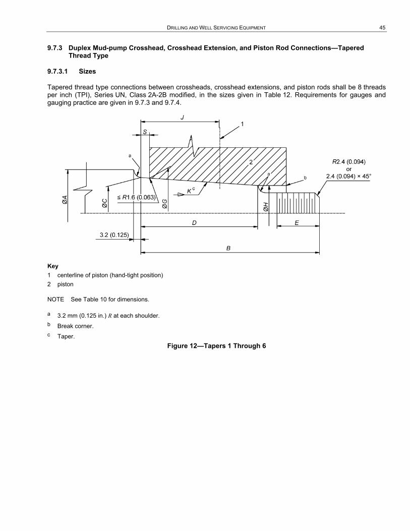
DRILLING AND WELL SERVICING EQUIPMENT 45
9.7.3 Duplex Mud-pump Crosshead, Crosshead Extension, and Piston Rod Connections—Tapered Thread Type
9.7.3.1 Sizes
Tapered thread type connections between crossheads, crosshead extensions, and piston rods shall be 8 threads per inch (TPI), Series UN, Class 2A-2B modified, in the sizes given in Table 12. Requirements for gauges and gauging practice are given in 9.7.3 and 9.7.4.
Key 1 centerline of piston (hand-tight position) 2 piston
NOTE See Table 10 for dimensions.
a 3.2 mm (0.125 in.) R at each shoulder. b Break corner. c Taper.
Figure 12—Tapers 1 Through 6
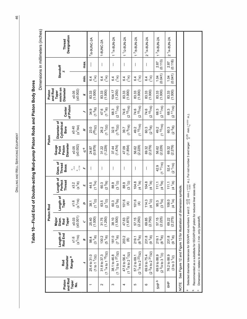
D
RIL
LIN
G A
ND
WE
LL S
ER
VIC
ING
EQ
UIP
ME
NT
46
Tabl
e 10
—Fl
uid
End
of D
oubl
e-ac
ting
Mud
-pum
p Pi
ston
Rod
s an
d Pi
ston
Bod
y B
ores
Dim
ensi
ons
in m
illim
eter
s (in
ches
)
Pist
on R
od
Pist
on
Pist
on
and
Rod
Ta
per
mm
/m o
n D
iam
eter
Thre
ad
Des
igna
tion
Pist
on
and
Rod
Ta
per
No.
Rod
D
iam
eter
R
ange
a
Leng
th o
f R
od E
nd
Maj
or
Dia
m.
Rod
Ta
per
Leng
th o
f Ta
per
Leng
th o
f Pe
rfec
t Th
read
Dia
m. o
f Th
read
B
oss
Gau
ge
Poin
t Pi
ston
D
iam
eter
Dia
met
er o
f C
ylin
dric
al
Bor
e C
ente
r of
Pis
ton
Stan
doff
S
±1.6
(±
1 /16
) ±0
.03
(±0.
001)
±1
.6
(±1 /
16)
±3.2
(±
1 /8)
06.1−
016/1−
±0
.05
(±0.
002)
±0
.40
(±1 /
64)
±0.0
5 (±
0.00
2)
A B
C D
E
F G
c
H
J K
m
in.
max
.
1 25
.4 to
31.
0 (1
to 1
7 /32
) 98
.4
(3 7 /
8)
25.4
0 (1
.000
) 38
.1
(1 1 /
2)
44.5
(1
3 /4)
—
24
.87
(0.9
79)
23.0
(29
/32)
34
.9
(1 3 /
8)
83.3
3 (1
.000
) 6.
4 (1 /
4)
—-
7 /8-
9UN
C-2
A
2 31
.8 to
37.
3 (1
1 /4
to 1
15/3
2)
130.
2 (5
1 /8)
31
.75
(1.2
50)
63.5
(2
1 /2)
60
.3
(2 3 /
8)
—
31.2
2 (1
.229
) 26
.2
(1 1 /
32)
47.6
(1
7 /8)
83
.33
(1.0
00)
6.4
(1 /4)
—
1-
8UN
C-2
A
3 38
.1 to
46.
8 (1
1 /2
to 1
27/3
2)
181.
0 (7
1 /8)
38
.10
(1.5
00)
60.3
(2
3 /8)
88
.9
(3 1 /
2)
—
37.4
4 (1
.474
) 32
.5
(1 9 /
32)
68.3
(2
11/1
6)
104.
17
(1.2
50)
6.4
(1 /4)
—
1
1 /4-
8UN
-2A
4 47
.6 to
56.
4 (1
7 /8
to 2
7 /32
) 20
3.2
(8)
47.6
3 (1
.875
) 10
1.6
(4)
88.9
(3
1 /2)
—
47
.09
(1.8
54)
39.7
(1
9 /16
) 74
.6
(2 15
/16)
83
.33
(1.0
00)
6.4
(1 /4)
—
1
1 /2-
8UN
-2A
5 57
.2 to
69.
1 (2
1 /4
to 2
23/3
2)
219.
1 (8
5 /8)
57
.15
(2.2
50)
101.
6 (4
) 10
4.8
(4 1 /
8)
—
56.6
2 (2
.229
) 49
.2
(1 15
/16)
74
.6
(2 15
/16)
83
.33
(1.0
00)
6.4
(1 /4)
—
1
7 /8-
8UN
-2A
6 69
.9 to
75.
4 (2
3 /4
to 2
31/3
2)
231.
8 (9
1 /8)
69
.85
(2.7
50)
114.
3 (4
1 /2)
10
4.8
(4 1 /
8)
—
69.3
2 (2
.279
) 60
.3
(2 3 /
8)
74.6
(2
15/1
6)
83.3
3 (1
.000
) 6.
4 (1 /
4)
—
2 1 /
4-8U
N-2
A
5HP
b 69
.9 to
88.
9 (2
3 /4
to 3
1 /2)
21
9.1
(8 5 /
8)
57.1
5 (2
.225
) 95
.3
(3 3 /
4)
111.
1 (4
3 /8)
42
.9
(1 11
/16)
56
.62
(2.2
29)
49.2
(1
15/1
6)
68.3
(2
11/1
6)
83.3
3 (1
.000
) 1.
04
(0.0
41)
2.87
(0
.113
) 1
7 /8-
8UN
-2A
6HP
76
.2 to
88.
9 (3
to 3
1 /2)
23
1.8
(9 1 /
8)
69.2
2 (2
.275
) 10
8.0
(4 1 /
4)
111.
1 (4
1 /8)
52
.4
(2 1 /
16)
69.3
2 (2
.279
) 60
.3
(2 3 /
8)
68.3
(2
11/1
6)
83.3
3 (1
.000
) 1.
04
(0.0
41)
2.87
(0
.118
) 2
1 /4-
8UN
-2A
NO
TE
See
Fig
ure
12 a
nd F
igur
e 13
for i
llust
ratio
n of
dim
ensi
on s
ymbo
ls.
a S
elec
ted
diam
eter
tole
ranc
es fo
r IS
O/A
PI r
od n
umbe
rs 1
and
2:
+ −0.25
0.13
mm
(01
0.000
5.0+ −
in.).
For
rod
num
ber 3
and
larg
er:
+0.2
50
mm
(01
0.0 0+
in.).
b
Rec
omm
ende
d as
a s
ubst
itute
for I
SO
/API
6H
P pi
ston
for r
educ
ed li
ner s
izes
onl
y.
c D
imen
sion
G re
late
s to
dim
ensi
on S
min
. onl
y (s
tand
off).
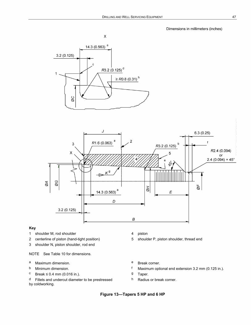
DRILLING AND WELL SERVICING EQUIPMENT 47
Key 1 shoulder M, rod shoulder 2 centerline of piston (hand-tight position) 3 shoulder N, piston shoulder, rod end
4 piston 5 shoulder P, piston shoulder, thread end
NOTE See Table 10 for dimensions.
a Maximum dimension. b Minimum dimension. c Break ≤ 0.4 mm (0.016 in.). d Fillets and undercut diameter to be prestressed by coldworking.
e Break corner. f Maximum optional end extension 3.2 mm (0.125 in.). g Taper. h Radius or break corner.
Figure 13—Tapers 5 HP and 6 HP
--``,``,```,,`````,`,,`,`,``,,`,-`-`,,`,,`,`,,`---

48 API SPECIFICATION 7K
Table 11—Fluid End of Single-acting Mud-pump Piston Rods and Piston Body Bores
Dimensions in millimeters (inches)
Piston and Rod
Connection Number
Connection Diameter Nominal mm (in.)
Piston Rod
Rod Diameter
A
Length Rod End
±1.6 (±1/16)
B
Start of Thread from
Shoulder max.
C
Shoulder Diameter
±0.4 (±1/64)
D
Thread Designation Piston Bore
SA-2 25.4 (1) 106.4 4 3/16
38.1 (1 1/2)
50.8 (2)
1-8UNC-2A 25.40 to 25.48(1.000 to 1.003)
SA-4 38.1 (1 1/2) A 138.1 5 7/16
47.6 (1 7/8)
82.6 (3 1/4)
1 1/2-8UN-2A 38.10 to 38.18(1.500 to 1.503)
NOTE See Figure 14 for illustration of dimension symbols.
Key 1 shoulder N, piston shoulder, rod end 2 seal required, dimensions are the option of manufacturer 3 piston 4 shoulder P, piston shoulder, thread end 5 shoulder M, rod shoulder 6 thread relief feature, details at option of manufacturer 7 last full thread
NOTE See Table 11 for dimensions.
a Optional feature.
Figure 14—Fluid End of Single-acting Mud-pump Piston Rod and Piston Body Bore
--``,``,```,,`````,`,,`,`,``,,`,-`-`,,`,,`,`,,`---
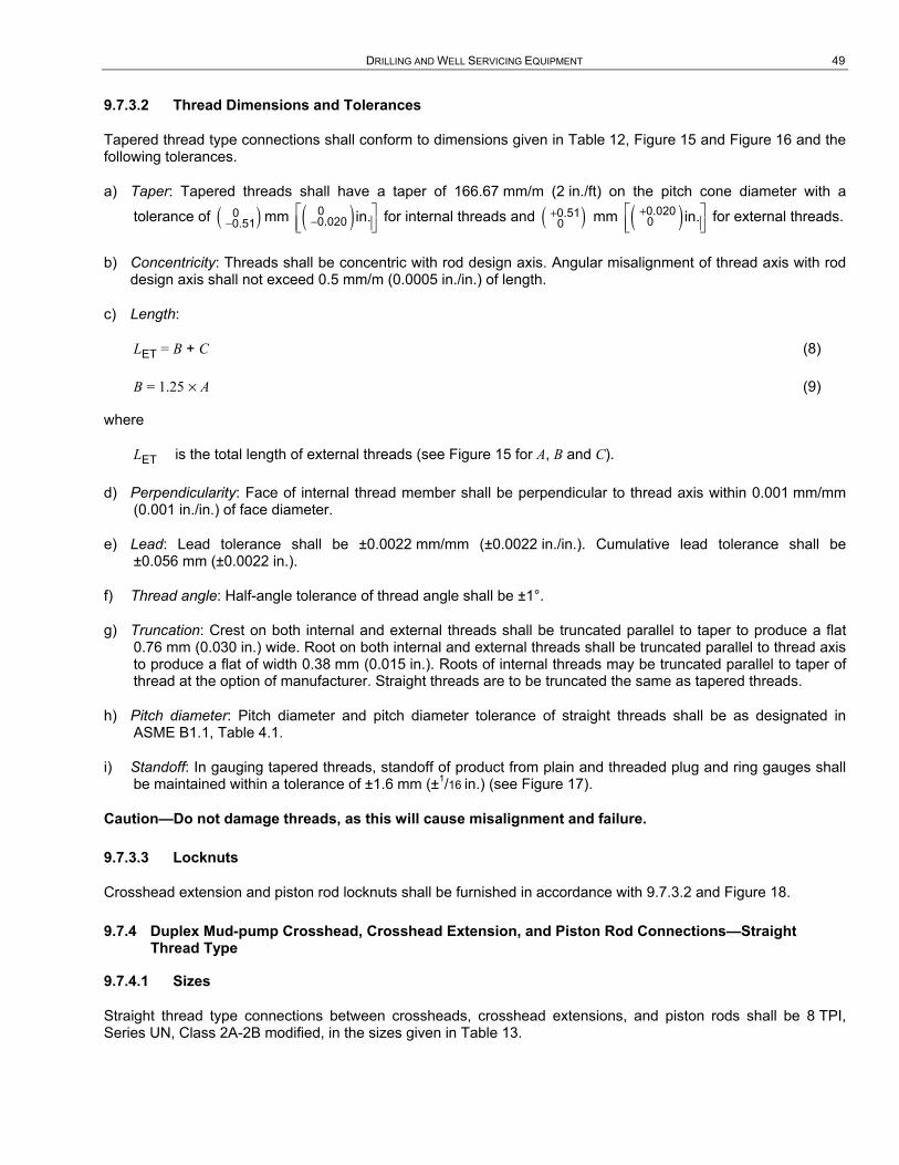
DRILLING AND WELL SERVICING EQUIPMENT 49
9.7.3.2 Thread Dimensions and Tolerances
Tapered thread type connections shall conform to dimensions given in Table 12, Figure 15 and Figure 16 and the following tolerances.
a) Taper: Tapered threads shall have a taper of 166.67 mm/m (2 in./ft) on the pitch cone diameter with a
tolerance of ( )−00.51 mm ( )−
⎡ ⎤⎢ ⎥⎣ ⎦
00.020 in. for internal threads and ( )+0.51
0 mm ( )+⎡ ⎤⎢ ⎥⎣ ⎦
0.0200 in. for external threads.
b) Concentricity: Threads shall be concentric with rod design axis. Angular misalignment of thread axis with rod design axis shall not exceed 0.5 mm/m (0.0005 in./in.) of length.
c) Length:
LET = B + C (8)
B = 1.25 × A (9)
where
LET is the total length of external threads (see Figure 15 for A, B and C).
d) Perpendicularity: Face of internal thread member shall be perpendicular to thread axis within 0.001 mm/mm (0.001 in./in.) of face diameter.
e) Lead: Lead tolerance shall be ±0.0022 mm/mm (±0.0022 in./in.). Cumulative lead tolerance shall be ±0.056 mm (±0.0022 in.).
f) Thread angle: Half-angle tolerance of thread angle shall be ±1°.
g) Truncation: Crest on both internal and external threads shall be truncated parallel to taper to produce a flat 0.76 mm (0.030 in.) wide. Root on both internal and external threads shall be truncated parallel to thread axis to produce a flat of width 0.38 mm (0.015 in.). Roots of internal threads may be truncated parallel to taper of thread at the option of manufacturer. Straight threads are to be truncated the same as tapered threads.
h) Pitch diameter: Pitch diameter and pitch diameter tolerance of straight threads shall be as designated in ASME B1.1, Table 4.1.
i) Standoff: In gauging tapered threads, standoff of product from plain and threaded plug and ring gauges shall be maintained within a tolerance of ±1.6 mm (±1/16 in.) (see Figure 17).
Caution—Do not damage threads, as this will cause misalignment and failure.
9.7.3.3 Locknuts
Crosshead extension and piston rod locknuts shall be furnished in accordance with 9.7.3.2 and Figure 18.
9.7.4 Duplex Mud-pump Crosshead, Crosshead Extension, and Piston Rod Connections—Straight Thread Type
9.7.4.1 Sizes
Straight thread type connections between crossheads, crosshead extensions, and piston rods shall be 8 TPI, Series UN, Class 2A-2B modified, in the sizes given in Table 13.
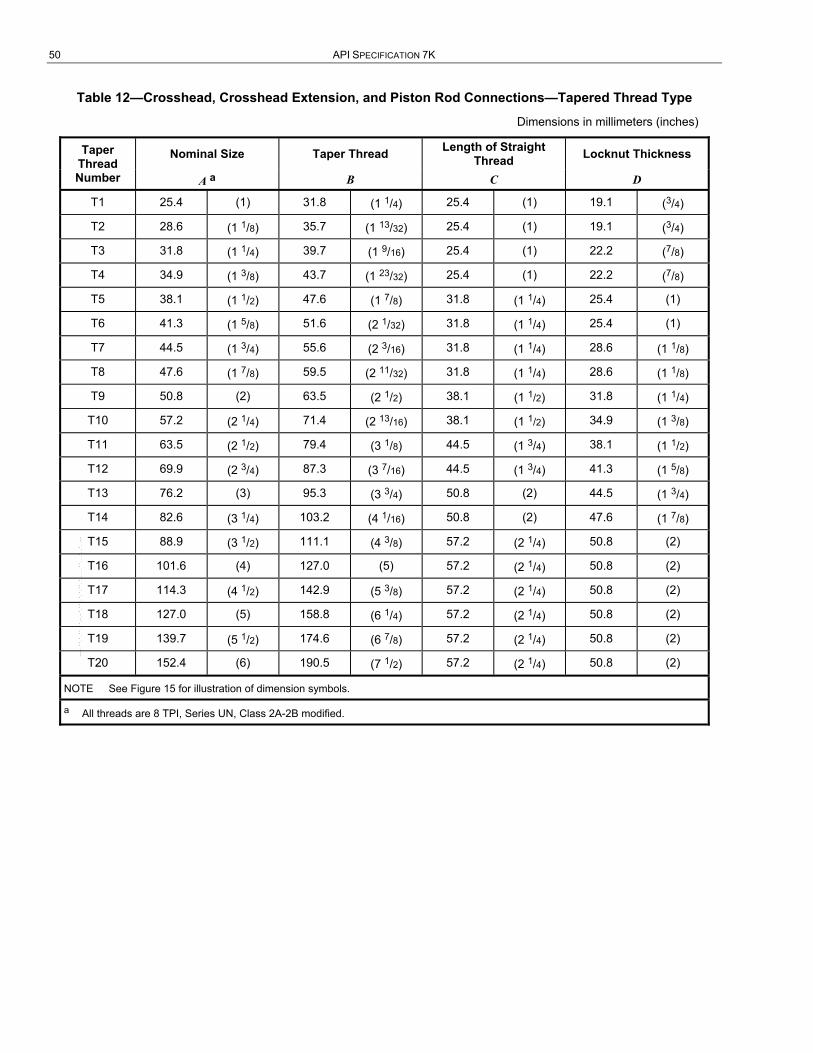
50 API SPECIFICATION 7K
Table 12—Crosshead, Crosshead Extension, and Piston Rod Connections—Tapered Thread Type
Dimensions in millimeters (inches)
Taper Thread Number
Nominal Size Taper Thread Length of Straight Thread Locknut Thickness
A a B C D
T1 25.4 (1) 31.8 (1 1/4) 25.4 (1) 19.1 (3/4)
T2 28.6 (1 1/8) 35.7 (1 13/32) 25.4 (1) 19.1 (3/4)
T3 31.8 (1 1/4) 39.7 (1 9/16) 25.4 (1) 22.2 (7/8)
T4 34.9 (1 3/8) 43.7 (1 23/32) 25.4 (1) 22.2 (7/8)
T5 38.1 (1 1/2) 47.6 (1 7/8) 31.8 (1 1/4) 25.4 (1)
T6 41.3 (1 5/8) 51.6 (2 1/32) 31.8 (1 1/4) 25.4 (1)
T7 44.5 (1 3/4) 55.6 (2 3/16) 31.8 (1 1/4) 28.6 (1 1/8)
T8 47.6 (1 7/8) 59.5 (2 11/32) 31.8 (1 1/4) 28.6 (1 1/8)
T9 50.8 (2) 63.5 (2 1/2) 38.1 (1 1/2) 31.8 (1 1/4)
T10 57.2 (2 1/4) 71.4 (2 13/16) 38.1 (1 1/2) 34.9 (1 3/8)
T11 63.5 (2 1/2) 79.4 (3 1/8) 44.5 (1 3/4) 38.1 (1 1/2)
T12 69.9 (2 3/4) 87.3 (3 7/16) 44.5 (1 3/4) 41.3 (1 5/8)
T13 76.2 (3) 95.3 (3 3/4) 50.8 (2) 44.5 (1 3/4)
T14 82.6 (3 1/4) 103.2 (4 1/16) 50.8 (2) 47.6 (1 7/8)
T15 88.9 (3 1/2) 111.1 (4 3/8) 57.2 (2 1/4) 50.8 (2)
T16 101.6 (4) 127.0 (5) 57.2 (2 1/4) 50.8 (2)
T17 114.3 (4 1/2) 142.9 (5 3/8) 57.2 (2 1/4) 50.8 (2)
T18 127.0 (5) 158.8 (6 1/4) 57.2 (2 1/4) 50.8 (2)
T19 139.7 (5 1/2) 174.6 (6 7/8) 57.2 (2 1/4) 50.8 (2)
T20 152.4 (6) 190.5 (7 1/2) 57.2 (2 1/4) 50.8 (2)
NOTE See Figure 15 for illustration of dimension symbols.
a All threads are 8 TPI, Series UN, Class 2A-2B modified.
--``,``,```,,`````,`,,`,`,``,,`,-`-`,,`,,`,`,,`---

DRILLING AND WELL SERVICING EQUIPMENT 51
Table 13—Crosshead, Crosshead Extension, and Piston Rod Connections—Straight Thread Type
Dimensions in millimeters (inches)
Straight Thread Number
Nominal Size A a
Length of Internal Thread
B
Length of External Thread
C
Locknut Thickness Minimum
D
S1 25.4 (1) 31.8 (1 1/4) 57.2 (2 1/4) 19.1 (3/4)
S2 28.6 (1 1/8) 35.7 (1 13/32) 61.1 (2 13/32) 19.1 (3/4)
S3 31.8 (1 1/4) 39.7 (1 9/16) 65.1 (2 9/16) 22.2 (7/8)
S4 34.9 (1 3/8) 43.7 (1 23/32) 69.1 (2 23/32) 22.2 (7/8)
S5 38.1 (1 1/2) 47.6 (1 7/8) 79.4 (3 1/8) 25.4 (1)
S6 41.3 (1 5/8) 51.6 (2 1/32) 83.3 (3 9/32) 25.4 (1)
S7 44.5 (1 3/4) 55.6 (2 3/16) 87.3 (3 7/16) 28.6 (1 1/8)
S8 47.6 (1 7/8) 59.5 (2 11/32) 91.3 (3 19/32) 28.6 (1 1/8)
S9 50.8 (2) 63.5 (2 1/2) 101.6 (4) 31.8 (1 1/4)
S10 57.2 (2 1/4) 71.4 (2 13/16) 109.5 (4 5/6) 34.9 (1 3/8)
S11 63.5 (2 1/2) 79.4 (3 1/8) 123.8 (4 7/8) 38.1 (1 1/2)
S12 69.9 (2 3/4) 87.3 (3 7/16) 131.8 (5 3/16) 41.3 (1 5/8)
S13 76.2 (3) 95.3 (3 3/4) 146.1 (5 3/4) 44.5 (1 3/4)
S14 82.6 (3 1/4) 103.2 (4 1/16) 154.0 (6 1/16) 47.6 (1 7/8)
S15 88.9 (3 1/2) 111.1 (4 3/8) 168.3 (6 5/8) 50.8 (2)
S16 101.6 (4) 127.0 (5) 184.2 (7 1/4) 50.8 (2)
S17 114.3 (4 1/2) 142.9 (5 5/8) 200.0 (7 7/8) 50.8 (2)
S18 127.0 (5) 158.8 (6 1/4) 215.9 (8 1/2) 50.8 (2)
S19 139.7 (5 1/2) 174.6 (6 7/8) 231.8 (9 1/8) 50.8 (2)
S20 152.4 (6) 190.5 (7 1/2) 247.7 (9 3/4) 50.8 (2)
NOTE See Figure 20 for illustration of dimension symbols.
a All threads are 8 TPI, Series UN, Class 2A-2B modified.

52 API SPECIFICATION 7K
Key 1 crosshead 2 locknut 3 crosshead extension 4 piston rod
NOTE See Table 12 for dimensions.
a 3.175 mm thread pitch (8 TPI) and 166.7 mm/m (2 in./ft) taper on pitch cone diameter.
Figure 15—Crosshead, Crosshead Extension, and Piston Rod Connections—Tapered Thread Type
--``,``,```,,`````,`,,`,`,``,,`,-`-`,,`,,`,`,,`---

DRILLING AND WELL SERVICING EQUIPMENT 53
Key 1 internal thread 2 external thread 3 thread axis
NOTE See 9.7.3.2 for description.
Figure 16—Tapered Thread Form
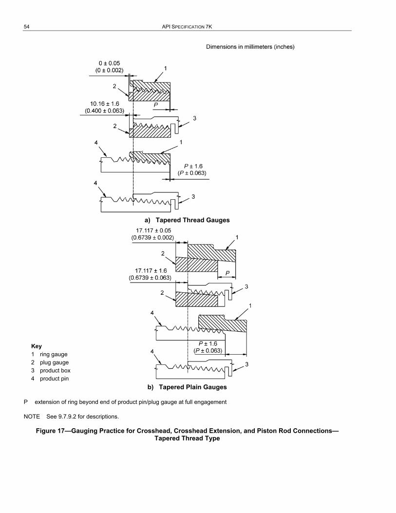
54 API SPECIFICATION 7K
a) Tapered Thread Gauges
Key 1 ring gauge 2 plug gauge 3 product box 4 product pin
b) Tapered Plain Gauges
P extension of ring beyond end of product pin/plug gauge at full engagement
NOTE See 9.7.9.2 for descriptions.
Figure 17—Gauging Practice for Crosshead, Crosshead Extension, and Piston Rod Connections—Tapered Thread Type

DRILLING AND WELL SERVICING EQUIPMENT 55
a Contact face shall be perpendicular to thread axis with a tolerance of ±0.001 mm/mm (0.001 in./in.) of face diameter.
Figure 18—Crosshead Extension and Piston Rod Locknut
9.7.4.2 Thread Dimensions and Tolerances
Straight-thread type connections shall conform to the dimensions and tolerances given in Table 13, Figure 19 and Figure 20, and ASME B1.1, and shall be gauged in accordance with ASME B1.2. The following requirements are also applicable.
a) Concentricity: Threads shall be concentric with rod design axis. Angular misalignment of thread axis with rod design axis shall not exceed 0.5 mm/m (0.0005 in./in.) of length.
b) Length (see Table 13):
1) internal: B = 1.25 × A; (10)
2) external: C = B + D + 6.4 mm. (11)
c) Perpendicularity: Face of internal thread member shall be perpendicular to thread axis within 1 mm/m (0.001 in./in.) of face diameter.
9.7.4.3 Locknuts
Crosshead extension and piston rod locknuts shall be furnished in accordance with Figure 20.
9.7.4.4 Taper Threads
Locknut threads for the taper type connection shall conform to the requirements of 9.7.3.2.
9.7.4.5 Threads
Locknut threads for the straight type connection shall conform to the requirements of 9.7.4.2.
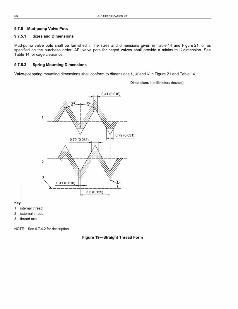
56 API SPECIFICATION 7K
9.7.5 Mud-pump Valve Pots
9.7.5.1 Sizes and Dimensions
Mud-pump valve pots shall be furnished in the sizes and dimensions given in Table 14 and Figure 21, or as specified on the purchase order. API valve pots for caged valves shall provide a minimum G dimension. See Table 14 for cage clearance.
9.7.5.2 Spring Mounting Dimensions
Valve-pot spring mounting dimensions shall conform to dimensions L, M and N in Figure 21 and Table 14.
Key 1 internal thread 2 external thread 3 thread axis
NOTE See 9.7.4.2 for description.
Figure 19—Straight Thread Form
--``,``,```,,`````,`,,`,`,``,,`,-`-`,,`,,`,`,,`---
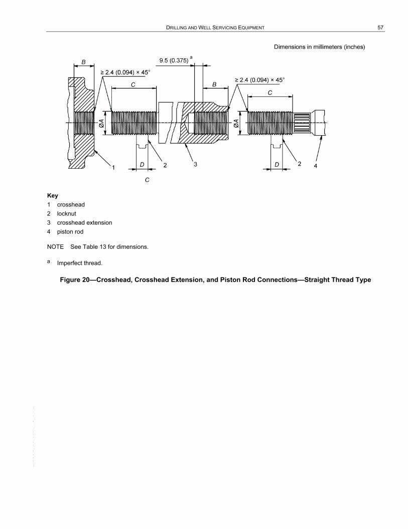
DRILLING AND WELL SERVICING EQUIPMENT 57
Key 1 crosshead 2 locknut 3 crosshead extension 4 piston rod
NOTE See Table 13 for dimensions.
a Imperfect thread.
Figure 20—Crosshead, Crosshead Extension, and Piston Rod Connections—Straight Thread Type
--``,``,```,,`````,`,,`,`,``,,`,-`-`,,`,,`,`,,`---
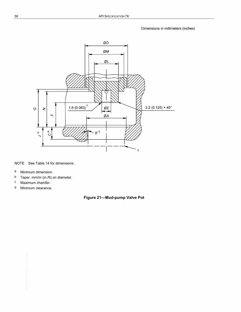
58 API SPECIFICATION 7K
NOTE See Table 14 for dimensions.
a Minimum dimension. b Taper, mm/m (in./ft) on diameter. c Maximum chamfer. d Minimum clearance.
Figure 21—Mud-pump Valve Pot
--``,``,```,,`````,`,,`,`,``,,`,-`-`,,`,,`,`,,`---

D
RIL
LIN
G A
ND
WE
LL S
ER
VIC
ING
EQ
UIP
ME
NT
59
Tabl
e 14
—M
ud-p
ump
Valv
e Po
ts
Dim
ensi
ons
in m
illim
eter
s (in
ches
)
Pot S
ize
Valv
e Po
t Dim
ensi
ons
Sprin
g M
ount
ing
Dim
ensi
ons
A B/
m
(B /f
t) C
D
E F
G
J L
M
N
1 73
.0 (2
7/8
) 16
6.7
(2)
25.4
(1)
82.6
(3 1
/4)
Solid
44
.5 (1
3/4
) So
lid
57.2
(2 1
/4)
25.4
(1)
63.5
(2 1
/2)
63.5
(2 1
/2)
2 85
.7 (3
3/8
) 16
6.7
(2)
28.6
(1 1
/8)
95.3
(3 3
/4)
20.6
(13 /
16)
57.2
(2 1
/4)
85.7
(3 3
/8)
63.5
(2 1
/2)
44.5
(1 3
/4)
76.2
(3)
82.6
(3 1
/4)
3 98
.4 (3
7/8
) 16
6.7
(2)
31.8
(1 1
/4)
108.
0 (4
1/4
) 20
.6 (1
3 /16
) 63
.5 (2
1/4
) 95
.3 (3
3/4
) 66
.7 (2
5/8
) 44
.5 (1
3/4
) 76
.2 (3
) 88
.9 (3
1/2
)
4 11
1.1
(4 3
/8)
166.
7 (2
) 34
.9 (1
3/8
) 12
0.7
(4 3
/4)
20.6
(13 /
16)
69.9
(2 3
/4)
104.
8 (4
1/8
) 69
.9 (2
3/4
) 50
.8 (2
) 76
.2 (3
) 95
.3 (3
3/4
)
5 12
7.0
(5)
166.
7 (2
) 38
.1 (1
1/2
) 13
6.5
(5 3
/8)
33.3
(1 5
/16)
76
.2 (3
) 12
3.8
(4 7
/8)
79.4
(3 1
/8)
69.9
(2 3
/4)
95.3
(3 3
/4)
108.
0 (4
1/4
)
5.5
136.
5 (5
3/8
) 16
6.7
(2)
41.3
(1 5
/8)
146.
1 (5
3/8
) 33
.3 (1
5/1
6)
82.6
(3 1
/4)
133.
4 (5
1/4
) 85
.7 (3
3/8
) 69
.9 (2
3/4
) 95
.3 (3
3/4
) 11
4.3
(4 1
/2)
6 14
2.9
(5 5
/8)
166.
7 (2
) 44
.5 (1
3/4
) 15
2.4
(6)
33.3
(1 5
/16)
82
.6 (3
1/4
) 13
3.4
(5 1
/4)
85.7
(3 3
/8)
69.9
(2 3
/4)
95.3
(3 3
/4)
114.
3 (4
1/2
)
7 15
8.8
(6 1
/4)
166.
7 (2
) 50
.8 (2
) 16
8.3
(6 5
/8)
33.3
(1 5
/16)
88
.9 (3
1/2
) 14
2.9
(5 5
/8)
95.3
(3 3
/4)
69.9
(2 3
/4)
95.3
(3 3
/4)
120.
7 (4
3/4
)
8 17
7.8
(7)
166.
7 (2
) 57
.2 (2
1/4
) 18
7.3
(3 1
/4)
33.3
(1 5
/16)
95
.3 (3
3/4
) 15
2.4
(6)
98.4
(3 7
/8)
69.9
(2 3
/4)
95.3
(3 3
/4)
127.
0 (5
)
9 19
6.9
(7 3
/4)
166.
7 (2
) 63
.5 (2
1/2
) 20
6.4
(8 1
/8)
33.3
(1 5
/16)
10
1.6
(4)
161.
9 (6
3/8
) 10
4.8
(4 1
/8)
69.9
(2 3
/4)
95.3
(3 3
/4)
133.
4 (5
1/4
)
10
215.
9 (8
1/2
) 16
6.7
(2)
73.0
(2 7
/8)
225.
4 (8
7/8
) 33
.3 (1
5/1
6)
108.
0 (4
1/4
) 17
1.5
(6 3
/4)
123.
8 (4
7/8
) 69
.9 (2
3/4
) 95
.3 (3
3/4
) 13
9.7
(5 1
/2)
11
241.
3 (9
1/2
) 16
6.7
(2)
82.6
(3 1
/4)
250.
8 (9
7/8
) 33
.3 (1
5/1
6)
114.
3(4
1 /2)
18
1.0
(7 1
/8)
136.
5 (5
3/8
) 69
.9 (2
3/4
) 95
.3 (3
3/4
) 14
6.1
(5 3
/4)
NO
TE
See
Fig
ure
21 fo
r illu
stra
tion
of d
imen
sion
sym
bols
.

60 API SPECIFICATION 7K
9.7.5.3 Marking
Mud-pump valve pots furnished in accordance with this specification shall be marked with the manufacturer’s name or mark, with “API 7K,” and the valve pot size number. Markings shall be cast or die stamped on the fluid cylinder or applied to a plate securely affixed to the fluid cylinder. Markings shall be applied in a location visible after installation of the fluid cylinder on the pump and may be applied to either pot. For pumps having divided fluid ends, each section shall be marked.
9.7.6 Mud-pump Pistons
9.7.6.1 Sizes and Dimensions
Mud-pump pistons shall be bored to fit standard taper of piston rods as given in Figure 12, Figure 13 and Table 10. Piston outside diameters shall be suitable for use in liners or cylinders having increments of diameter change as noted in 9.7.7.1 and Figure 22.
9.7.6.2 Marking
Pistons conforming to this specification shall be marked with the manufacturer’s name or mark, the number of this specification (API 7K), the corresponding API rod number, and standard bore. Markings shall be stamped in letters 3.2 mm (1/8 in.) high on the end face of piston core at the large end of the piston-rod hole.
9.7.7 Mud-pump Liners
9.7.7.1 Liner Bores
Bores of mud-pump liners 152.4 mm (6 in.) in diameter and larger shall be supplied in 6.35 mm (1/4 in.) increments. Bores smaller than 152.4 mm (6 in.) in diameter shall be supplied in 12.7 mm (1/2 in.) increments. Bore tolerances shall be as noted in Figure 22 or as specified on the purchase order.
9.7.7.2 Chamfer
The inside edge of the piston entering end of mud-pump liners shall be chamfered as shown in Figure 22.
9.7.7.3 Marking
Mud-pump liners conforming to this specification shall be marked with the manufacturer’s name or mark, the number of this specification (API 7K), and the size (standard bore) of the liner. Markings shall be stamped in letters 3.2 mm (1/8 in.) high on the outer end of the liner.
9.7.8 Mud-pump Gear Ratings
9.7.8.1 Provisions
Ratings are based on surface durability (which is independent of pitch). However, the gear manufacturer shall assume responsibility for selecting a pitch sufficiently coarse to provide adequate tooth strength.
9.7.8.2 Design
Gears shall be single reduction, either helical or herringbone. Gear materials shall be in accordance with AGMA 2004-C08. Gear strength and durability shall be determined in accordance with a national standard or code. Any practical combination of tooth height, pressure angle, or helix angle may be used. However, American Gear Manufacturers Association (AGMA) standards are recommended. The mud-pump manufacturer shall be responsible for adequate shafting and support to maintain proper alignment under load.
9.7.8.3 Nameplate Rating
The nameplate (power) rating of a mud pump shall not exceed the (power) rating of the gears.
--``,``,```,,`````,`,,`,`,``,,`,-`-`,,`,,`,`,,`---
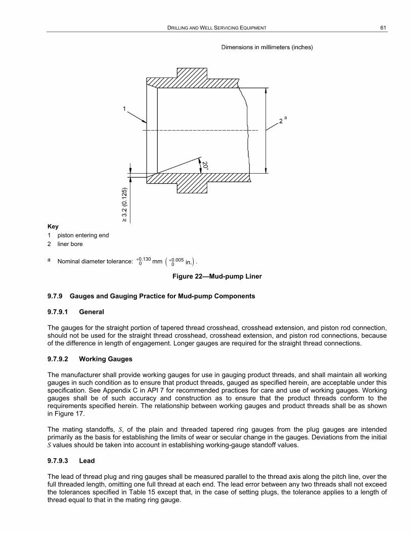
DRILLING AND WELL SERVICING EQUIPMENT 61
Key 1 piston entering end 2 liner bore
a Nominal diameter tolerance: +0.1300 mm ( )+0.005
0 in. .
Figure 22—Mud-pump Liner
9.7.9 Gauges and Gauging Practice for Mud-pump Components
9.7.9.1 General
The gauges for the straight portion of tapered thread crosshead, crosshead extension, and piston rod connection, should not be used for the straight thread crosshead, crosshead extension, and piston rod connections, because of the difference in length of engagement. Longer gauges are required for the straight thread connections.
9.7.9.2 Working Gauges
The manufacturer shall provide working gauges for use in gauging product threads, and shall maintain all working gauges in such condition as to ensure that product threads, gauged as specified herein, are acceptable under this specification. See Appendix C in API 7 for recommended practices for care and use of working gauges. Working gauges shall be of such accuracy and construction as to ensure that the product threads conform to the requirements specified herein. The relationship between working gauges and product threads shall be as shown in Figure 17.
The mating standoffs, S, of the plain and threaded tapered ring gauges from the plug gauges are intended primarily as the basis for establishing the limits of wear or secular change in the gauges. Deviations from the initial S values should be taken into account in establishing working-gauge standoff values.
9.7.9.3 Lead
The lead of thread plug and ring gauges shall be measured parallel to the thread axis along the pitch line, over the full threaded length, omitting one full thread at each end. The lead error between any two threads shall not exceed the tolerances specified in Table 15 except that, in the case of setting plugs, the tolerance applies to a length of thread equal to that in the mating ring gauge.

62 API SPECIFICATION 7K
9.7.9.4 Taper
The included taper of tapered thread gauges shall be measured on the diameter along the pitch line over the full threaded length, omitting approximately one full thread at each end. The taper determined as above, and computed to the length LRT (see Table 16) shall conform to the basic taper within the tolerances specified in Table 15. The included taper of plain tapered plug and ring gauges shall be measured on the diameter over the full length, omitting approximately 1.6 mm (1/16 in.) of length at each end. The taper as determined above, and computed to the length LRP (see Table 16 and Table 17), shall conform to the basic taper within the tolerance specified in Table 15. The taper of straight thread setting plugs shall not exceed 0.0038 mm (0.00015 in.) over the length, LTS (see Table 18, Table 19 and Figure 24). The permissible taper shall be back taper (largest diameter at the entering end) and shall be confined within the pitch diameter limits.
9.7.9.5 Fit
Go and no-go adjustable straight-thread ring gauges shall be set to snug-fit at full engagement on their mating plugs. An adjustable ring gauge shall be set initially on either the full form or the truncated portion of the setting plug. When screwed onto the other portion of the setting plug, there shall be only a slight change in fit, if any. If there is perceptible shake or play in the looser fit, the ring and, if necessary, the plug shall be reconditioned.
9.7.9.6 Root Form
The roots of tapered-thread plug and ring gauges shall be approximately sharp with a radius not exceeding 0.25 mm (0.010 in.), or undercut to a maximum width equivalent to the basic root truncation given in Table 22. The undercut shall be substantially symmetrical with respect to the adjoining thread flanks and of such depth as to clear the basic sharp thread; otherwise, the shape of the undercut shall be optional with the gauge manufacturer.
9.7.9.7 Thread Roots
The thread roots of go thread plug and ring gauges, no-go thread plug and ring gauges, and setting thread plug gauges for the straight thread on the pin and the thread in the locknut shall be as specified in ASME B1.2. See Table 15, Table 16, Table 17, Table 18, Table 19, Figure 24, Figure 25, and Figure 26 for dimensional tolerances.
--``,``,```,,`````,`,,`,`,``,,`,-`-`,,`,,`,`,,`---
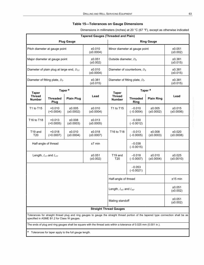
DRILLING AND WELL SERVICING EQUIPMENT 63
Table 15—Tolerances on Gauge Dimensions
Dimensions in millimeters (inches) at 20 °C (67 °F), except as otherwise indicated
Tapered Gauges (Threaded and Plain)
Plug Gauge Ring Gauge
Pitch diameter at gauge point ±0.010 (±0.0004)
Minor diameter at gauge point ±0.051 (±0.002)
Major diameter at gauge point ±0.051 (±0.002)
Outside diameter, DR ±0.381 (±0.015)
Diameter of plain plug at large end, DFP ±0.010 (±0.0004)
Diameter of counterbore, DR ±0.381 (±0.015)
Diameter of fitting plate, DP ±0.381 (±0.015)
Diameter of fitting plate, DP ±0.381 (±0.015)
Taper Thread Number
Taper a
Lead Taper
Thread Number
Taper a
Lead Threaded
Plug Plain Plug Threaded
Ring Plain Ring
T1 to T15 +0.010 (+0.0004)
±0.005 (±0.0002)
±0.010 (±0.0004)
T1 to T15 −0.010 (−0.0004)
±0.005 (±0.0002)
±0.015 (±0.0006)
T16 to T18 +0.013 (+0.0005)
±0.008 (±0.0003)
±0.013 (±0.0005)
−0.030 (−0.0012)
T19 and T20
+0.018 (+0.0007)
±0.010 (±0.0004)
±0.018 (±0.0007)
T16 to T18 −0.013 (−0.0005)
±0.008 (±0.0003)
±0.020 (±0.0008)
Half-angle of thread ±7 min −0.038 (−0.0015)
Length, LPT and LPP ±0.051 (±0.002)
T19 and T20
−0.018 (−0.0007)
±0.010 (±0.0004)
±0.025 (±0.0010)
−0.053 (−0.0021)
Half-angle of thread ±15 min
Length, LRT and LRP ±0.051 (±0.002)
Mating standoff ±0.051 (±0.002)
Straight Thread Gauges
Tolerances for straight thread plug and ring gauges to gauge the straight thread portion of the tapered type connection shall be as specified in ASME B1.2 for Class W gauges.
The ends of plug and ring gauges shall be square with the thread axis within a tolerance of 0.025 mm (0.001 in.).
a Tolerances for taper apply to the full gauge length.
--``,``,```,,`````,`,,`,`,``,,`,-`-`,,`,,`,`,,`---

64 API SPECIFICATION 7K
Table 16—Tapered Thread and Plain Gauges a
Dimensions in millimeters at 20 °C
Taper Thread Number
Nom. Size
Outside Diam.
of Ring
Tapered Thread Gauges b Tapered Plain Gauges
Pitch Diam. at Gauge Point
Major Diam. at Gauge Point
Minor Diam. at Gauge Point
Diam. of
Fitting Plate
Length of Plug
and Ring
Diam. of Counter-
bore
Diam. of Plug at
Large End
Diam. of Ring at
Large End
Length of Plug
and Ring
DR DP LPT and LRT DC DEP DER LPP and
LRP
T1 1 60.3 21.9304 23.3568 20.5039 17.27 41.910 29.11 24.6268 21.7739 31.750
T2 1 1/8 63.5 25.1016 26.5280 23.6751 20.45 45.878 32.28 27.7980 24.9451 35.718
T3 1 1/4 66.7 28.2753 29.7017 26.8488 23.62 49.848 35.46 30.9718 28.1188 39.688
T4 1 3/8 69.9 31.4452 32.8717 30.0187 26.80 53.818 38.63 34.1417 31.2887 43.658
T5 1 1/2 73.0 34.6189 36.0454 33.1925 29.97 57.785 41.81 37.3154 34.4625 47.625
T6 1 5/8 76.2 37.7927 39.2191 36.3593 33.15 61.752 44.98 40.4891 37.6362 51.593
T7 1 3/4 79.4 40.9638 42.3903 39.5374 36.32 65.723 48.16 43.6603 40.8074 55.563
T8 1 7/8 82.6 44.1363 45.5628 42.7098 39.50 69.693 51.33 46.8328 43.9800 59.533
T9 2 85.7 47.3100 48.7365 45.8836 42.67 73.660 54.51 50.0065 47.1536 63.500
T10 2 1/4 92.1 53.6550 55.0814 52.2285 49.00 81.598 60.83 56.3514 53.4985 71.438
T11 2 1/2 98.4 60.0024 61.4289 58.5760 55.35 89.535 67.18 62.6989 59.8460 79.375
T12 2 3/4 117.5 66.3485 67.7751 64.9221 61.70 97.473 73.53 69.0451 66.1921 87.313
T13 3 123.8 72.6935 74.1200 71.2671 68.05 105.410 79.88 75.3899 72.5371 92.250
T14 3 1/4 130.2 79.0410 80.4675 77.6145 74.40 113.348 86.23 81.7375 78.8845 103.188
T15 3 1/2 136.5 85.3897 86.8162 83.9633 80.75 121.285 92.58 88.0862 85.2333 111.125
T16 4 149.2 98.0834 99.5098 96.6569 93.45 137.160 105.28 100.7798 97.9270 127.000
T17 4 1/2 161.9 110.777 112.2035 109.3506 106.12 153.035 117.96 113.4735 110.6206 142.875
T18 5 174.6 123.471 124.8971 122.0442 118.82 168.910 130.65 126.1671 123.3142 158.750
T19 5 1/2 187.3 136.166 137.5921 134.7391 131.52 184.785 143.36 138.8620 136.0091 174.625
T20 6 200.0 148.862 150.2882 147.4353 144.22 200.660 156.06 151.5582 148.7053 190.500
NOTE See Figure 23 for illustration of dimension symbols.
a Taper for all sizes is 166.67 mm/m on diameter. b All threads are 8 TPI, pitch = 3.175 mm.
--``,``,```,,`````,`,,`,`,``,,`,-`-`,,`,,`,`,,`---
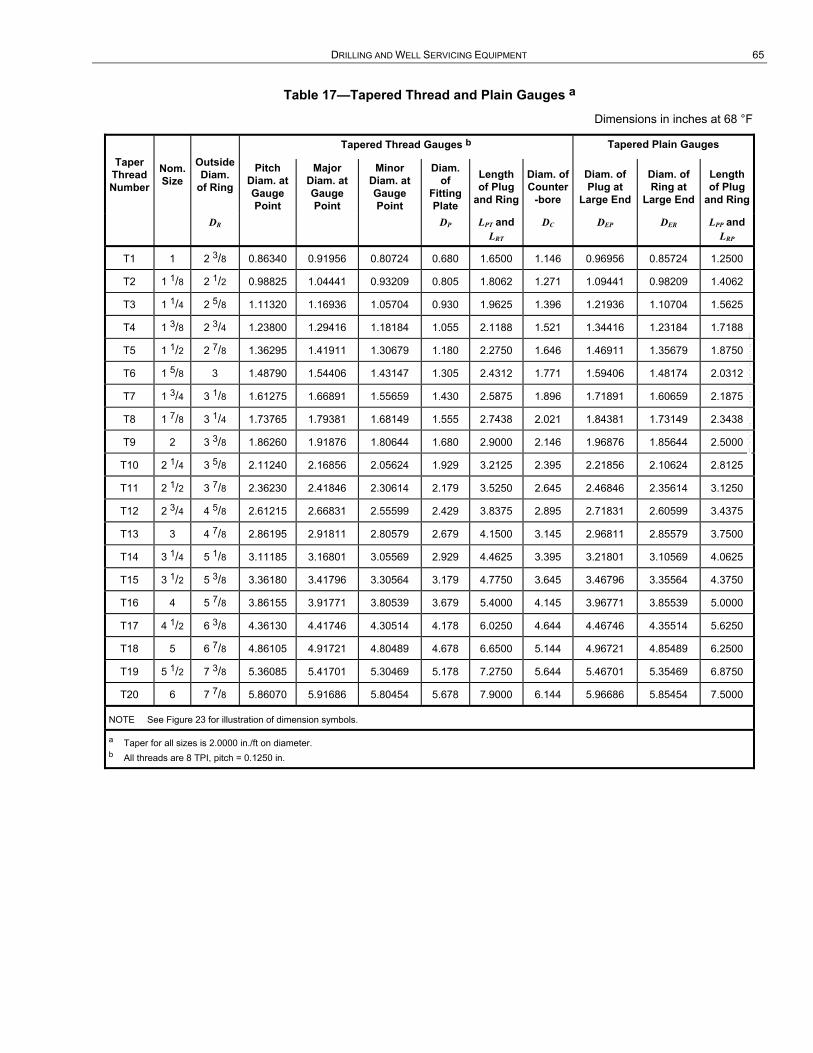
DRILLING AND WELL SERVICING EQUIPMENT 65
Table 17—Tapered Thread and Plain Gauges a
Dimensions in inches at 68 °F
Taper Thread Number
Nom. Size
Outside Diam.
of Ring
Tapered Thread Gauges b Tapered Plain Gauges
Pitch Diam. at Gauge Point
Major Diam. at Gauge Point
Minor Diam. at Gauge Point
Diam. of
Fitting Plate
Length of Plug
and Ring
Diam. of Counter
-bore
Diam. of Plug at
Large End
Diam. of Ring at
Large End
Length of Plug
and Ring
DR DP LPT and LRT
DC DEP DER LPP and LRP
T1 1 2 3/8 0.86340 0.91956 0.80724 0.680 1.6500 1.146 0.96956 0.85724 1.2500
T2 1 1/8 2 1/2 0.98825 1.04441 0.93209 0.805 1.8062 1.271 1.09441 0.98209 1.4062
T3 1 1/4 2 5/8 1.11320 1.16936 1.05704 0.930 1.9625 1.396 1.21936 1.10704 1.5625
T4 1 3/8 2 3/4 1.23800 1.29416 1.18184 1.055 2.1188 1.521 1.34416 1.23184 1.7188
T5 1 1/2 2 7/8 1.36295 1.41911 1.30679 1.180 2.2750 1.646 1.46911 1.35679 1.8750
T6 1 5/8 3 1.48790 1.54406 1.43147 1.305 2.4312 1.771 1.59406 1.48174 2.0312
T7 1 3/4 3 1/8 1.61275 1.66891 1.55659 1.430 2.5875 1.896 1.71891 1.60659 2.1875
T8 1 7/8 3 1/4 1.73765 1.79381 1.68149 1.555 2.7438 2.021 1.84381 1.73149 2.3438
T9 2 3 3/8 1.86260 1.91876 1.80644 1.680 2.9000 2.146 1.96876 1.85644 2.5000
T10 2 1/4 3 5/8 2.11240 2.16856 2.05624 1.929 3.2125 2.395 2.21856 2.10624 2.8125
T11 2 1/2 3 7/8 2.36230 2.41846 2.30614 2.179 3.5250 2.645 2.46846 2.35614 3.1250
T12 2 3/4 4 5/8 2.61215 2.66831 2.55599 2.429 3.8375 2.895 2.71831 2.60599 3.4375
T13 3 4 7/8 2.86195 2.91811 2.80579 2.679 4.1500 3.145 2.96811 2.85579 3.7500
T14 3 1/4 5 1/8 3.11185 3.16801 3.05569 2.929 4.4625 3.395 3.21801 3.10569 4.0625
T15 3 1/2 5 3/8 3.36180 3.41796 3.30564 3.179 4.7750 3.645 3.46796 3.35564 4.3750
T16 4 5 7/8 3.86155 3.91771 3.80539 3.679 5.4000 4.145 3.96771 3.85539 5.0000
T17 4 1/2 6 3/8 4.36130 4.41746 4.30514 4.178 6.0250 4.644 4.46746 4.35514 5.6250
T18 5 6 7/8 4.86105 4.91721 4.80489 4.678 6.6500 5.144 4.96721 4.85489 6.2500
T19 5 1/2 7 3/8 5.36085 5.41701 5.30469 5.178 7.2750 5.644 5.46701 5.35469 6.8750
T20 6 7 7/8 5.86070 5.91686 5.80454 5.678 7.9000 6.144 5.96686 5.85454 7.5000
NOTE See Figure 23 for illustration of dimension symbols.
a Taper for all sizes is 2.0000 in./ft on diameter. b All threads are 8 TPI, pitch = 0.1250 in.
--``,``,```,,`````,`,,`,`,``,,`,-`-`,,`,,`,`,,`---

66 API SPECIFICATION 7K
a) Tapered Thread Gauge
b) Tapered Plain Gauge
Key 1 plane of gauge point
NOTE See Table 16 and Table 17 for dimensions.
a 9.5 mm to 19.1 mm (0.375 in. to 0.75 in.). Dimension varies with gauge size.
Figure 23—Tapered-thread and Plain Gauges
--``,``,```,,`````,`,,`,`,``,,`,-`-`,,`,,`,`,,`---

DRILLING AND WELL SERVICING EQUIPMENT 67
Table 18—Pin Go and No-go Gauges a (for Straight Threaded Portion of Tapered Thread Connection)
Dimensions in millimeters at 20 °C
Taper Thread Number
Nom. Size
Full Form Major Diam.
Go Gauges No-go Gauges
Truncated Major Diam.
Pitch Diam.
Thread Length
Ring Length
Ring Minor Diam.
Truncated Major Diam.
Pitch Diam.
Thread Length
Ring Length
Ring Minor Diam.
BS BST ES LTS LN KN BST ES LTS LN KN
T1 1 24.717 24.282 23.287 53.975 23.8 21.857 23.828 23.114 38.1 17.5 22.400
T2 1 1/8 27.889 27.455 26.459 53.975 23.8 25.029 26.998 26.284 38.1 17.5 25.570
T3 1 1/4 31.064 30.630 29.634 60.325 28.6 28.204 30.170 29.456 41.3 19.1 28.743
T4 1 3/8 34.237 33.802 32.807 60.325 28.6 31.377 33.338 32.624 41.3 19.1 31.910
T5 1 1/2 37.411 36.977 35.982 60.325 28.6 34.552 36.510 35.796 41.3 19.1 35.082
T6 1 5/8 40.587 40.152 39.157 73.025 31.8 37.727 39.682 38.969 47.6 20.6 38.255
T7 1 3/4 43.759 43.325 42.329 73.025 31.8 40.900 42.852 42.139 47.6 20.6 41.425
T8 1 7/8 46.934 46.500 45.504 73.025 31.8 44.074 46.022 45.309 47.6 20.6 44.595
T9 2 50.109 49.675 48.679 73.025 31.8 47.249 49.195 48.481 47.6 20.6 47.767
T10 2 1/4 56.457 56.022 55.027 76.200 34.9 53.597 55.537 54.823 50.8 22.2 54.110
T11 2 1/2 62.807 62.372 61.377 82.550 38.1 59.947 61.882 61.168 50.8 22.2 60.455
T12 2 3/4 69.154 68.720 67.724 88.900 41.3 66.294 68.227 67.513 50.8 22.2 66.799
T13 3 75.502 75.067 74.071 95.250 44.5 72.641 74.569 73.856 50.8 22.2 73.142
T14 3 1/4 81.852 81.417 80.421 101.600 47.6 78.991 80.914 80.201 50.8 23.8 79.487
T15 3 1/2 88.202 87.767 86.771 107.950 50.8 85.341 87.262 86.548 50.8 23.8 85.834
T16 4 100.899 100.465 99.469 107.950 50.8 98.039 99.952 99.238 50.8 23.8 98.524
T17 4 1/2 113.596 113.162 112.166 107.950 50.8 110.736 112.641 111.928 54.0 25.4 111.214
T18 5 126.294 125.860 124.864 107.950 50.8 123.434 125.331 124.617 54.0 25.4 123.904
T19 5 1/2 138.991 138.557 137.561 107.950 50.8 136.131 138.024 137.310 54.0 25.4 136.596
T20 6 151.691 151.257 150.261 107.950 50.8 148.831 150.716 150.002 54.0 25.4 149.289
NOTE See Figure 24 for illustration of dimension symbols.
a All threads are 8 TPI, pitch = 3.175 mm.

68 API SPECIFICATION 7K
Table 19—Pin Go and No-go Gauges a (for Straight-threaded Portion of Tapered-thread Connection)
Dimensions in inches at 68 °F
Taper Thread Number
Nom. Size
Full Form Major Diam.
Go Gauges Ring Minor Diam.
No-go Gauges
Truncated Major Diam.
Pitch Diam.
Thread Length
Ring Length
Truncated Major Diam.
Pitch Diam.
Thread Length
Ring Length
Ring Minor Diam.
BS BST ES LTS LN KN BST LS LTS LN KN
T1 1 0.9731 0.9560 0.9168 2 1/8 15/16 0.8605 0.9381 0.9100 1 1/2 11/16 0.8819
T2 1 1/8 1.0980 1.0809 1.0417 2 1/8 15/16 0.9854 1.0629 1.0348 1 1/2 11/16 1.0067
T3 1 1/4 1.2230 1.2059 1.1667 2 3/8 1 1/8 1.1104 1.1878 1.1597 1 5/8 3/4 1.1316
T4 1 3/8 1.3479 1.3308 1.2916 2 3/8 1 1/8 1.2353 1.3125 1.2844 1 5/8 3/4 1.2563
T5 1 1/2 1.4729 1.4558 1.4166 2 3/8 1 1/8 1.3603 1.4374 1.4093 1 5/8 3/4 1.3812
T6 1 5/8 1.5979 1.5808 1.5416 2 7/8 1 1/4 1.4853 1.5623 1.5342 1 7/8 13/16 1.5061
T7 1 3/4 1.7228 1.7057 1.6665 2 7/8 1 1/4 1.6102 1.6871 1.6590 1 7/8 13/16 1.6309
T8 1 7/8 1.8478 1.8307 1.7915 2 7/8 1 1/4 1.7352 1.8119 1.7838 1 7/8 13/16 1.7557
T9 2 1.9728 1.9557 1.9165 2 7/8 1 1/4 1.8602 1.9368 1.9087 1 7/8 13/16 1.8806
T10 2 1/4 2.2227 2.2056 2.1664 3 1 3/8 2.1101 2.1865 2.1584 2 7/8 2.1303
T11 2 1/2 2.4727 2.4556 2.4164 3 1/4 1 1/2 2.3601 2.4363 2.4082 2 7/8 2.3801
T12 2 3/4 2.7226 2.7055 2.6663 3 1/2 1 5/8 2.6100 2.6861 2.6580 2 7/8 2.6299
T13 3 2.9725 2.9554 2.9162 3 3/4 1 3/4 2.8599 2.9358 2.9077 2 7/8 2.8796
T14 3 1/4 3.2225 3.2054 3.1662 4 1 7/8 3.1099 3.1856 3.1575 2 15/16 3.1294
T15 3 1/2 3.4725 3.4554 3.4162 4 1/4 2 3.3599 3.4355 3.4074 2 15/16 3.3793
T16 4 3.9724 3.9553 3.9161 4 1/4 2 3.8598 3.9351 3.9070 2 15/16 3.8789
T17 4 1/2 4.4723 4.4552 4.4160 4 1/4 2 4.3597 4.4347 4.4066 2 1/8 1 4.3785
T18 5 4.9722 4.9551 4.9159 4 1/4 2 4.8596 4.9343 4.9062 2 1/8 1 4.8781
T19 5 1/2 5.4721 5.4550 5.4158 4 1/4 2 5.3595 5.4340 5.4059 2 1/8 1 5.3778
T20 6 5.9721 5.9550 5.9158 4 1/4 2 5.8595 5.9337 5.9056 2 1/8 1 5.8775
NOTE See Figure 24 for illustration of dimension symbols.
a All threads are 8 TPI, pitch = 0.1250 in.
--``,``,```,,`````,`,,`,`,``,,`,-`-`,,`,,`,`,,`---

DRILLING AND WELL SERVICING EQUIPMENT 69
Table 20—Box Go and No-go Gauges a (for Locknut)
Dimensions in millimeters at 20 °C
Taper Thread Number
Nominal Size
Go Gauges No-go Gauges
Major Diameter
Pitch Diameter
Thread Length
Major Diameter
Pitch Diameter
Thread Length
BS ES LT BS ES LT
T1 1 24.768 23.338 25.4 24.275 23.561 15.9
T2 1 1/8 27.943 26.513 25.4 27.455 26.741 15.9
T3 1 1/4 31.118 29.688 31.8 30.635 29.921 19.1
T4 1 3/8 34.293 32.863 31.8 33.813 33.099 19.1
T5 1 1/2 37.468 36.038 31.8 36.993 36.279 19.1
T6 1 5/8 40.643 39.213 31.8 40.173 39.459 22.2
T7 1 3/4 43.818 42.388 31.8 43.350 42.636 22.2
T8 1 7/8 46.993 45.563 31.8 46.530 45.817 22.2
T9 2 50.168 48.738 31.8 49.708 48.994 22.2
T10 2 1/4 56.518 55.088 34.9 56.065 55.352 22.2
T11 2 1/2 62.868 61.438 50.8 62.421 61.707 22.2
T12 2 3/4 69.218 67.788 54.0 68.776 68.062 25.4
T13 3 75.568 74.138 54.0 75.133 74.420 25.4
T14 3 1/4 81.918 80.488 57.2 81.488 80.775 25.4
T15 3 1/2 88.268 86.838 57.2 87.843 87.130 25.4
T16 4 100.968 99.538 57.2 100.554 99.840 25.4
T17 4 1/2 113.668 112.238 57.2 113.261 112.547 25.4
T18 5 126.368 124.938 57.2 125.971 125.258 25.4
T19 5 1/2 139.068 137.638 57.2 138.679 137.965 25.4
T20 6 151.768 150.338 57.2 151.387 150.673 25.4
NOTE See Figure 25 for illustration of dimension symbols.
a All threads are 8 TPI, pitch = 3.175 mm.
--``,``,```,,`````,`,,`,`,``,,`,-`-`,,`,,`,`,,`---
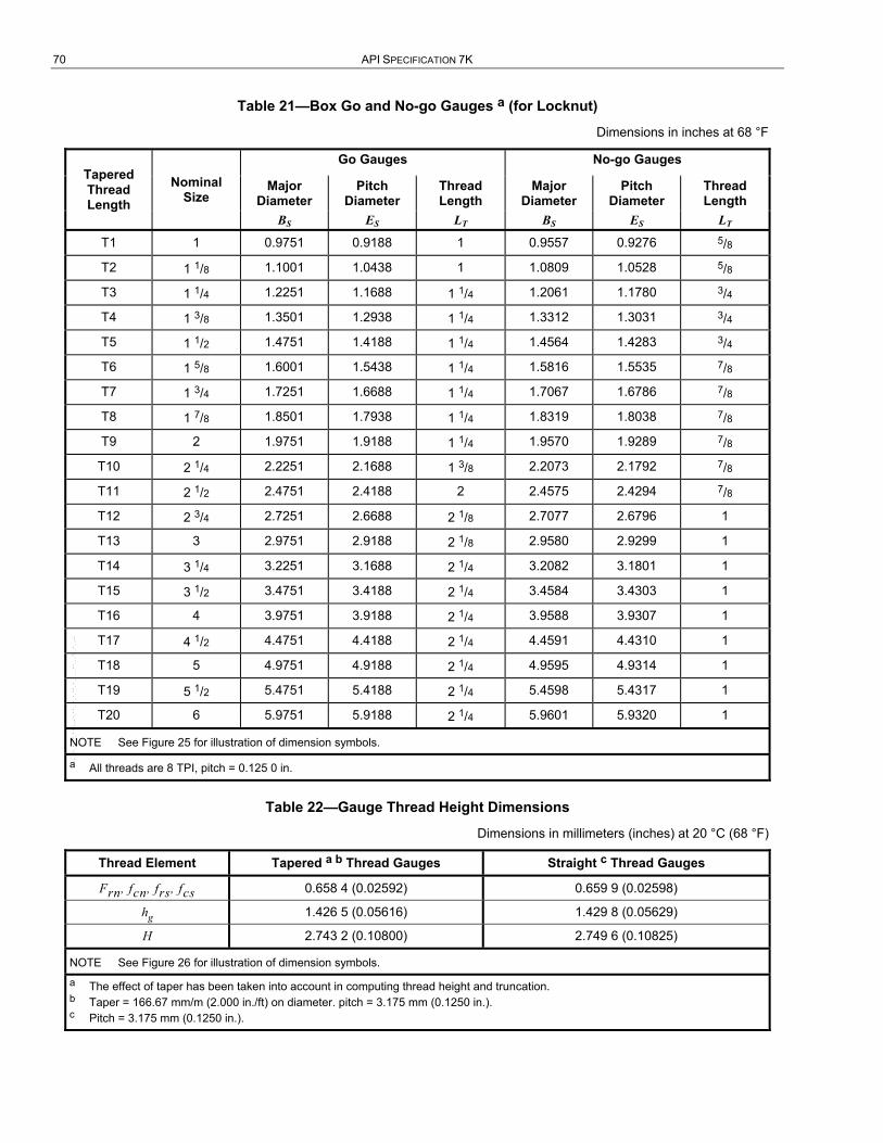
70 API SPECIFICATION 7K
Table 21—Box Go and No-go Gauges a (for Locknut)
Dimensions in inches at 68 °F
Tapered Thread Length
Nominal Size
Go Gauges No-go Gauges
Major Diameter
Pitch Diameter
Thread Length
Major Diameter
Pitch Diameter
Thread Length
BS ES LT BS ES LT
T1 1 0.9751 0.9188 1 0.9557 0.9276 5/8
T2 1 1/8 1.1001 1.0438 1 1.0809 1.0528 5/8
T3 1 1/4 1.2251 1.1688 1 1/4 1.2061 1.1780 3/4
T4 1 3/8 1.3501 1.2938 1 1/4 1.3312 1.3031 3/4
T5 1 1/2 1.4751 1.4188 1 1/4 1.4564 1.4283 3/4
T6 1 5/8 1.6001 1.5438 1 1/4 1.5816 1.5535 7/8
T7 1 3/4 1.7251 1.6688 1 1/4 1.7067 1.6786 7/8
T8 1 7/8 1.8501 1.7938 1 1/4 1.8319 1.8038 7/8
T9 2 1.9751 1.9188 1 1/4 1.9570 1.9289 7/8
T10 2 1/4 2.2251 2.1688 1 3/8 2.2073 2.1792 7/8
T11 2 1/2 2.4751 2.4188 2 2.4575 2.4294 7/8
T12 2 3/4 2.7251 2.6688 2 1/8 2.7077 2.6796 1
T13 3 2.9751 2.9188 2 1/8 2.9580 2.9299 1
T14 3 1/4 3.2251 3.1688 2 1/4 3.2082 3.1801 1
T15 3 1/2 3.4751 3.4188 2 1/4 3.4584 3.4303 1
T16 4 3.9751 3.9188 2 1/4 3.9588 3.9307 1
T17 4 1/2 4.4751 4.4188 2 1/4 4.4591 4.4310 1
T18 5 4.9751 4.9188 2 1/4 4.9595 4.9314 1
T19 5 1/2 5.4751 5.4188 2 1/4 5.4598 5.4317 1
T20 6 5.9751 5.9188 2 1/4 5.9601 5.9320 1
NOTE See Figure 25 for illustration of dimension symbols.
a All threads are 8 TPI, pitch = 0.125 0 in.
Table 22—Gauge Thread Height Dimensions
Dimensions in millimeters (inches) at 20 °C (68 °F)
Thread Element Tapered a b Thread Gauges Straight c Thread Gauges
Frn, fcn, frs, fcs 0.658 4 (0.02592) 0.659 9 (0.02598)
hg 1.426 5 (0.05616) 1.429 8 (0.05629)
H 2.743 2 (0.10800) 2.749 6 (0.10825)
NOTE See Figure 26 for illustration of dimension symbols.
a The effect of taper has been taken into account in computing thread height and truncation. b Taper = 166.67 mm/m (2.000 in./ft) on diameter. pitch = 3.175 mm (0.1250 in.). c Pitch = 3.175 mm (0.1250 in.).
--``,``,```,,`````,`,,`,`,``,,`,-`-`,,`,,`,`,,`---

DRILLING AND WELL SERVICING EQUIPMENT 71
NOTE See Table 18 and Table 19 for dimensions.
Figure 24—Pin Go and No-go Gauges (for Straight-threaded Portion of Tapered-thread Connection)
NOTE See Table 20 and Table 21 for dimensions.
Figure 25—Box Go and No-go Gauges (for Locknut)
--``,``,```,,`````,`,,`,`,``,,`,-`-`,,`,,`,`,,`---

72 API SPECIFICATION 7K
Key 1 internal thread 2 external thread 3 thread axis 4 pitch
NOTE See Table 22 for dimensions.
Figure 26—Gauge Thread Form
9.7.9.8 Pitch Diameter
In computing pitch diameter, the effect of helix angle shall be disregarded.
9.7.9.9 Initial Standoff
The large ends of tapered-thread gauges shall be flush within ±0.05 mm (±0.002 in.). The standoff of plain tapered gauges shall be 17.117 ± 0.05 mm (0.6739 ± 0.002 in.).
9.7.9.10 Determination of Standoff
Mating standoff (as illustrated in Figure 17 and Figure 23) shall be determined as follows.
a) During the test all pieces entering into the measurement shall be at a uniform temperature near 20 °C (68 °F).
b) Gauges shall be benzene-cleaned before mating. Gauges shall be made up within a thin film of white mineral oil of grade and viscosity such as Nujol 12, Squibb’s liquid petrolatum 12 or equivalent, wiped onto threads with a clean chamois skin or bristle brush.
c) The pair shall be mated hand-tight without spinning into place, and complete register shall be accomplished with the torque hammer as shown in Figure 27 using the following weights:
⎯ for gauges T1 to T9, use a 0.45 kg (1 lb) weight;
⎯ for gauges T10 to T13, use a 0.91 kg (2 lb) weight;
⎯ for gauges T14 to T17, use a 1.36 kg (3 lb) weight;
12 This term is used as an example only, and does not constitute an endorsement of this product by API.
--``,``,```,,`````,`,,`,`,``,,`,-`-`,,`,,`,`,,`---
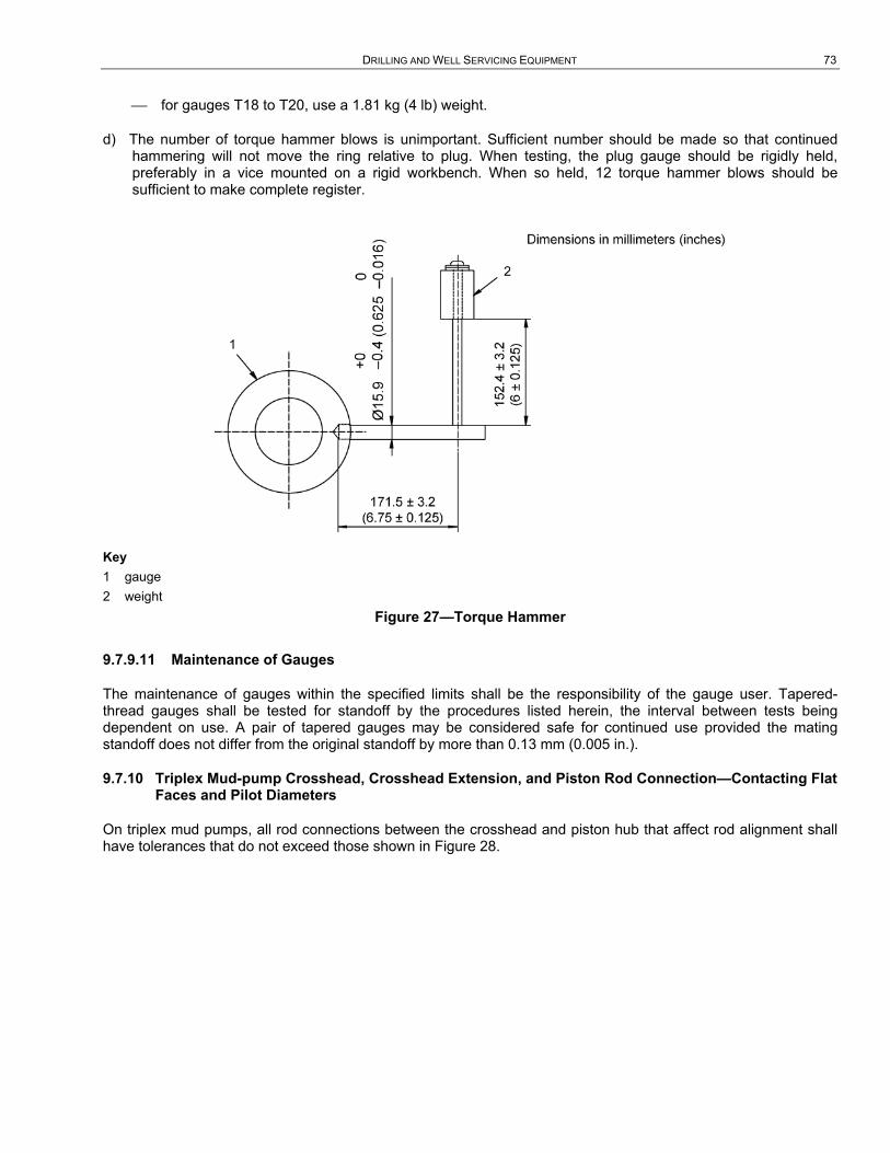
DRILLING AND WELL SERVICING EQUIPMENT 73
⎯ for gauges T18 to T20, use a 1.81 kg (4 lb) weight.
d) The number of torque hammer blows is unimportant. Sufficient number should be made so that continued hammering will not move the ring relative to plug. When testing, the plug gauge should be rigidly held, preferably in a vice mounted on a rigid workbench. When so held, 12 torque hammer blows should be sufficient to make complete register.
Key 1 gauge 2 weight
Figure 27—Torque Hammer
9.7.9.11 Maintenance of Gauges
The maintenance of gauges within the specified limits shall be the responsibility of the gauge user. Tapered-thread gauges shall be tested for standoff by the procedures listed herein, the interval between tests being dependent on use. A pair of tapered gauges may be considered safe for continued use provided the mating standoff does not differ from the original standoff by more than 0.13 mm (0.005 in.).
9.7.10 Triplex Mud-pump Crosshead, Crosshead Extension, and Piston Rod Connection—Contacting Flat Faces and Pilot Diameters
On triplex mud pumps, all rod connections between the crosshead and piston hub that affect rod alignment shall have tolerances that do not exceed those shown in Figure 28.

74 API SPECIFICATION 7K
Key 1 face diameter
a Contacting flat faces or mating rod connections, and crosshead extension shall be perpendicular to centerline of rod with a tolerance of 0.0005 m/m (0.0005 in./in.) of face diameter.
b Concentricity tolerance between pilot diameter’s centerline and theoretical centerline of rod shall not exceed 0.13 mm (0.005 in.).
Figure 28—Contacting Flat Faces and Pilot Diameters on Mating Connections from Crosshead Extension to Piston Hub on Mud Pumps
9.8 Drawworks Components
9.8.1 Primary Load Path
The primary load-path components for a drawworks shall be limited to those loaded by the fast-line load when the main drum brake is engaged. The manufacturer/designer shall use accepted design practices and shall determine factors of safety, except as otherwise specified within this specification.
9.8.2 Requirements
The requirements of 4.2.7, 5.4, 5.5, 5.6, 6.3.1, 8.4.4, 8.4.5, 8.4.7, and 8.4.8 shall not apply, except as noted below. For antifriction bearing design and manufacturing requirements, see 9.19.
9.8.3 Line-shaft Extension for Cathead
Line-shaft extensions for catheads shall be furnished as specified on the purchase order unless the drawworks is furnished with integral catheads.
DRILLING AND WELL SERVICING EQUIPMENT 75
9.8.4 Brake Bands for Main Drum
9.8.4.1 General
Main drum brakes are generally band or disk types, but other designs are not precluded by this specification.
9.8.4.2 Design Safety Factor (DSF)
The minimum DSF for the structural strength of main drum brake bands shall be 3.0, based on the drawworks’ rated design fast-line pull at the median drum working radius, or the second layer of working rope, whichever is greater.
9.8.4.3 Weldments
9.8.4.3.1 The design load capacity of the weldment shall not be less than the minimum design load capacity of the band only.
9.8.4.3.2 Weldments shall be reviewed for the effect of weld stress concentration as it affects fatigue life of the weldments.
9.8.4.4 Quality Control
9.8.4.4.1 All castings and welds shall be inspected in accordance with 8.4.7.
9.8.4.4.2 All accessible surfaces of the band shall be visually inspected after all manufacturing operations are completed. Indications with a length of less than three times the width are acceptable, provided the major dimension is less than 4 mm (1/8 in.) and they meet other criteria established in 8.4.7.4 for wrought material. No indications with a length equal to or greater than three times the width are acceptable. No indications at the edges, including hole edges, of the band are acceptable.
9.8.4.4.3 The inside radius on a band, between tangent points, shall not deviate more than ±0.5 % from the design radius. The inside radii measured at the edges of a band at any circumferential point on the band shall not vary more than ±0.5 % of the bandwidth at that point.
9.8.4.4.4 Maximum allowable weld undercut shall be in accordance with AWS D1.1, except that there shall be none for any transverse welds.
9.9 Manual Spiders that use Standard Rotary Slips
9.9.1 General
Spider bodies furnished in conformance with this specification that use standard rotary slips not capable of use as elevators and installed on or above the master bushing/rotary table (see 1 c)), shall be marked with the manufacturer’s name or mark and the rating.
9.9.2 Component Traceability
Primary load-carrying components shall be uniquely marked as specified in 8.4.5.
9.9.3 Serialization
Each complete item of equipment shall be marked with a unique serial number that shall provide traceability to its manufacturing history.
9.9.4 Impact Toughness
The following impact toughness values apply to primary load-carrying components of spiders.
--``,``,```,,`````,`,,`,`,``,,`,-`-`,,`,,`,`,,`---
76 API SPECIFICATION 7K
a) Components with a specified minimum yield strength of at least 310 MPa (45,000 psi) shall be made from materials possessing a minimum impact toughness of 33 J (25 ft-lb) at –20 °C (–4 °F). The specified minimum impact toughness shall be an average of three tests, with no individual value less than 26 J (19 ft-lb).
b) For components with a specified minimum yield strength of less than 310 MPa (45,000 psi), the –20 °C (-4 °F) minimum impact toughness shall be 27 J (20 ft-lb) with no individual value less than 20 J (15 ft-lb).
9.9.5 Design Verification Test
The design verification load test, as described in Section 5, shall apply.
9.9.6 Proof Load Test
Proof load testing, as described in 8.6, shall apply. The following shall apply to spiders and manual tongs:
a) replacement hinge pins and latch pins shall meet or exceed the original manufacturer’s specifications;
b) replacement hinge pins and latch pins manufactured from wrought material are exempt from proof load testing requirements.
9.10 Manual Spiders that use Nonstandard Rotary Slips
9.10.1 General
Spider bodies furnished in conformance with this specification that use rotary slips with a nonstandard taper, not capable of use as elevators, and installed on or above the master bushing/rotary table, shall be marked with the manufacturer’s name or mark and the rating.
9.10.2 Component Traceability
Primary load-carrying components shall be uniquely marked as specified in 8.4.5.
9.10.3 Serialization
Each complete item of equipment shall be marked with a unique serial number that shall provide traceability to its manufacturing history.
9.10.4 Impact Toughness
The following impact toughness values apply to primary load-carrying components of spiders.
a) Components with a specified minimum yield strength of at least 310 MPa (45,000 psi) shall be made from materials possessing a minimum impact toughness of 33 J (25 ft-lb) at –20 °C (–4 °F). The specified minimum impact toughness shall be an average of three tests, with no individual value less than 26 J (19 ft-lb).
b) For components with a specified minimum yield strength of less than 310 MPa (45,000 psi), the –20 °C (-4 °F) minimum impact toughness shall be 27 J (20 ft-lb) with no individual value less than 20 J (15 ft-lb).
9.10.5 Design Verification Test
The design verification load test, as described in Section 5, shall apply.
9.10.6 Proof Load Test
Proof load testing, as described in 8.6, shall apply. The following shall apply to spiders and manual tongs:
--``,``,```,,`````,`,,`,`,``,,`,-`-`,,`,,`,`,,`---

DRILLING AND WELL SERVICING EQUIPMENT 77
a) replacement hinge pins and latch pins shall meet or exceed the original manufacturer’s specifications;
b) replacement hinge pins and latch pins manufactured from wrought material are exempt from proof load testing requirements.
9.11 Spring, Pneumatic, or Hydraulic Spiders Installed on or above the Master Bushing/Rotary Table
9.11.1 General
Spider bodies furnished in conformance with this specification with integral slips not capable of use as elevators, installed on or above the master bushing/rotary table shall be marked with the manufacturer’s name or mark and the rating.
9.11.2 Component traceability
Primary load-carrying components shall be uniquely marked as specified in 8.4.5.
9.11.3 Serialization
Each complete item of equipment shall be marked with a unique serial number that shall provide traceability to its manufacturing history.
9.11.4 Impact Toughness
The following impact toughness values apply to primary load-carrying components of spiders.
a) Components with a specified minimum yield strength of at least 310 MPa (45,000 psi) shall be made from materials possessing a minimum impact toughness of 33 J (25 ft-lb) at –20 °C (–4 °F). The specified minimum impact toughness shall be an average of three tests, with no individual value less than 26 J (19 ft-lb).
b) For components with a specified minimum yield strength of less than 310 MPa (45,000 psi), the –20 °C (-4 °F) minimum impact toughness shall be 27 J (20 ft-lb) with no individual value less than 20 J (15 ft-lb).
9.11.5 Design Verification Test
The design verification load test, as described in Section 5, shall apply.
9.11.6 Proof Load Test
Proof load testing, as described in 8.6, shall apply. The following shall apply to spiders and manual tongs:
a) replacement hinge pins and latch pins shall meet or exceed the original manufacturer’s specifications;
b) replacement hinge pins and latch pins manufactured from wrought material are exempt from proof load testing requirements.
9.12 Spring, Pneumatic, or Hydraulic Spiders Installed in, or partly in, the Rotary Table
9.12.1 General
Spider bodies furnished in conformance with this specification with integral slips not capable of use as elevators, installed in, or partly in, the rotary table shall be marked with the manufacturer’s name or mark and the rating.
9.12.2 Component Traceability
Primary load-carrying components shall be uniquely marked as specified in 8.4.5.
--``,``,```,,`````,`,,`,`,``,,`,-`-`,,`,,`,`,,`---
78 API SPECIFICATION 7K
9.12.3 Serialization
Each complete item of equipment shall be marked with a unique serial number that shall provide traceability to its manufacturing history.
9.12.4 Impact Toughness
The following impact toughness values apply to primary load-carrying components of spiders.
a) Components with a specified minimum yield strength of at least 310 MPa (45,000 psi) shall be made from materials possessing a minimum impact toughness of 33 J (25 ft-lb) at –20 °C (–4 °F). The specified minimum impact toughness shall be an average of three tests, with no individual value less than 26 J (19 ft-lb).
b) For components with a specified minimum yield strength of less than 310 MPa (45,000 psi), the –20 °C (–4 °F) minimum impact toughness shall be 27 J (20 ft-lb) with no individual value less than 20 J (15 ft-lb).
9.12.5 Design Verification Test
The design verification load test, as described in Section 5, shall apply.
9.12.6 Proof Load Test
Proof load testing, as described in 8.6, shall apply.
9.13 Manual Tongs
9.13.1 Product Marking
Manual tongs furnished in conformance with this specification shall be marked with the manufacturer’s name or mark and the rated load.
9.13.2 Size Class Designation
The size class designation for manual tongs shall represent the diameter, or range of diameters, for which the tong is designed.
9.13.3 Impact Toughness
9.13.3.1 The following impact toughness values apply to primary load-path components except hinge pins.
a) Components with a specified minimum yield strength of at least 310 MPa (45,000 psi) shall be from materials possessing a minimum impact toughness of 42 J (31 ft-lb) at −20 °C (−4 °F). The specified minimum impact toughness shall be an average of three tests, with no individual values less than 32 J (24 ft-lb).
b) For components with a specified minimum yield strength of less than 310 MPa (45,000 psi), the −20 °C (−4 °F) minimum impact toughness shall be 27 J (20 ft-lb) with no individual values less than 20 J (15 ft-lb).
9.13.3.2 Hinge pins shall have a minimum impact toughness of 15 J (11 ft-lb) at −20 °C (−4 °F). The specified minimum impact toughness shall be an average of three tests, with no individual value less than 12 J (8.5 ft-lb).
9.13.4 Component Traceability
Primary load-carrying components shall be uniquely marked as specified in 8.4.5.
9.13.5 Design Verification Load Tests
The design verification load test, as described in Section 5, shall apply.

DRILLING AND WELL SERVICING EQUIPMENT 79
9.13.6 Proof Load Testing
Proof load testing, as described in 8.6, shall apply. Jaw hinge pins of wrought material shall be exempt from this requirement.
9.14 Safety Clamps Not Used as a Hoisting Device
9.14.1 Load rating of safety clamps is not required.
9.14.2 The requirements of 6.3.1, 8.4.4, 8.4.5, 8.4.8, and 8.4.9 shall not apply.
9.14.3 The requirements of 8.4.7 apply to safety clamps except that the method and acceptance criteria of MSS SP-53 shall apply.
9.15 Power Tongs
9.15.1 Product Marking
Power tongs furnished in conformance with this specification shall be marked with the manufacturer’s name or mark and size class.
9.15.2 Size Class Designation
The size class designation for power tongs shall represent the diameter, or range of diameters, for which the tong is designed.
9.15.3 Requirements
The requirements of 4.2.7, 5.3, 5.4, 5.5, 5.6, 6.3, and Section 8 in its entirety shall not apply.
9.15.4 Primary Load Path
The primary load path shall be considered to be the mechanical elements (exclusive of hydraulic power transmission components) through which the torque is applied or resisted.
9.16 BOP Handling Systems and Equipment
9.16.1 Applicability of the Requirements in Section 1 Through 8
9.16.1.1 Sections 4.1, 4.5, and 4.6 covering design requirements and DSFs shall not apply to this equipment. Such requirements for this equipment shall be in accordance with 9.16.3, 9.16.4, and 9.16.5.
9.16.1.2 Section 4.2.7 regarding fatigue life shall apply to this equipment, or as specified by the manufacturer in accordance with 9.16.8.
9.16.1.3 Section 4.4.1 covering rotary tables, spiders, manual, and power tongs shall not apply to this equipment.
9.16.1.4 Section 4.4.3 covering torque ratings for power and manual tongs shall not apply to this equipment.
9.16.1.5 Production proof load testing required in 8.6, and as further specified in 9.16.6, shall be required unless it is waived by the purchaser in the purchase agreement.
--``,``,```,,`````,`,,`,`,``,,`,-`-`,,`,,`,`,,`---

80 API SPECIFICATION 7K
9.16.2 Requirements for Purchaser-defined Information and Specifications in Purchase Agreements for BOP Handling Systems
9.16.2.1 General
The requirements in 9.16.2.2 and 9.16.2.3 shall be specified by the purchaser in purchase agreements issued for BOP handling systems covered by this standard.
9.16.2.2 Control System Features
The purchaser shall specify control system features, such as load monitoring and logging (specify USC or SI units), audio/visual alarms, operational displays and ergonomics, any fail-safe shut-downs or other safety features not specified in this standard, and control system functionality such as defaults, interlocks, and detents, redundancy features, manual overrides, trouble-shooting devices, and back-up power supplies and software, etc. Control systems shall be designed so as to prevent unexpected movement of the system when power is interrupted, and when restored after interruption, of power (e.g. electrical, pneumatic, and hydraulic). The controls shall be designed to prevent unexpected movement regardless of whether one source, or multiple sources, of power are interrupted and subsequently restored.
9.16.2.3 Ambient Conditions
The purchaser shall specify the environment in which the system is anticipated to operate in terms of maximum and minimum temperatures and humidity levels, the corrosiveness of the atmosphere such as whether the system will be used offshore or onshore, and any other ambient conditions that could affect the design or manufacture of the system that would be reasonably anticipated.
9.16.2.4 Other Systems Interface Requirements
9.16.2.4.1 The purchaser shall identify the other systems that the BOP handling system will interface with physically as well as functionally. This type of interface may include but not be limited to rig system control and monitoring systems (including software compatibility), BOP stack storage structure(s), moonpool guidance systems, and/or structural interface required to distribute and support the primary load of the handling system. The latter requirement should include a transmittal of relevant rig structural drawings to the manufacturer needed to design appropriate system structure to interface with the rig structure.
9.16.2.4.2 When it is intended that the system is to receive power supplies from the rig after it is installed, the purchaser shall specify the sources of electrical, hydraulic, and/or pneumatic power that is to be made available to supply power to the system.
9.16.2.4.3 The purchaser shall specify the applicable codes, standards, and regulatory requirements that shall apply to electrical equipment, components, fittings, and cabling and their installation, including applicable requirements for hazardous area or zone classifications in which the BOP handling system is to be installed.
9.16.2.4.4 The purchaser, at his/her option, shall specify the type of third party certification required for the system.
9.16.2.4.5 The purchaser shall specify whether a production proof-load test in accordance with 8.6 and 9.16.6 shall be performed by the manufacturer prior to delivery.
9.16.2.5 Loading Conditions
9.16.2.5.1 The purchaser shall specify the anticipated maximum static load that will be handled by the system, which shall include the entire BOP stack and all of its attachments, including but not limited to bell nipple assembly, work platforms, conductor tensioner system components, drilling spools, high-pressure risers, wellhead spools, choke and kill valves and piping, etc.
9.16.2.5.2 The purchaser shall specify the dynamic factors that the system will be exposed to, including, but not limited to maximum wind velocity, accelerations caused during transportation if the system is portable,
DRILLING AND WELL SERVICING EQUIPMENT 81
accelerations caused by offshore vessel motion criteria, side loading and/or operation requirements at angles misaligned with the normal load path, and/or other dynamic forces that would be anticipated during system operation.
9.16.3 Subsystem Design Requirements
9.16.3.1 General
Design requirements and specifications of subsystems and/or system components are specified as follows.
9.16.3.2 Piping Systems
Valve DSFs shall meet or exceed those required by ASME B16.34 and NFPA T2.12.10 R1. For piping systems, safety factors shall meet or exceed the requirements specified in ASME B31.3, Hydraulic circuit design shall incorporate features that will allow isolation of components such as pressure relief, pressure regulating, and counter-balance valves for replacement and maintenance without having to drain the system of hydraulic fluid. Functional redundancy and bypass circuits shall also be employed to increase reliability. Flexible hoses shall only be utilized where there is a requirement to address misalignment, relative movement between components, thermal expansion and contraction, and vibration. Otherwise, rigid-piping/tubing shall be utilized.
9.16.3.3 Wire Rope
For wire rope components other than slings covered by 9.16.3.4, the working load limit shall be based on a wire rope design factor of 5. If the end termination used with the wire rope develops the full wire rope strength (100 % efficient) then the working load limit is the wire rope’s published minimum breaking force divided by five. If the wire rope termination used with the wire rope is less than 100 % efficient, then the working load limit is the wire rope’s published minimum breaking force times the termination efficiency divided by five. Similarly, the published wire rope breaking strength shall be de-rated for bending over sheaves or drums in accordance with API 9B or other published manufacturer’s data. For any type of termination, the equation for determining the working load limit is:
FDEffFBMWLL ×= (12)
where
WLL is the working load limit;
MBF is the minimum breaking force of wire rope;
Eff is the end termination frequency;
DF is the design factor.
NOTE Typical efficiencies for properly designed, applied, and maintained wire rope end terminations are:
a) open or closed spelter sockets, 100 %;
b) open or closed swaged sockets, 100 %;
c) wire rope clips, 80 %;
d) wedge sockets, 75 % to 80 %.
9.16.3.4 Slings
Slings made from wire rope, chain, or synthetic materials shall be fabricated and certified per ASME B30.9 or equivalent. Wire rope slings incorporate the end termination efficiency and a wire rope design factor of five in their rated capacity. The rated capacity of each sling is shown on the tag attached to the sling.
--``,``,```,,`````,`,,`,`,``,,`,-`-`,,`,,`,`,,`---

82 API SPECIFICATION 7K
9.16.3.5 Off-the-shelf Loose Gear
Off-the-shelf loose gear selected for use in BOP handling systems, such as shackles, hooks, chain, binders, swivels, turnbuckles, sheave blocks, and connecting links, shall have a working load limit published by the manufacturer that equals or exceeds the design load of the load path they are used in.
9.16.3.6 Single Sheave Blocks
The resultant load on a single sheave block as illustrated below in Figure 29 and its attachment to supporting structure shall not exceed the working load limit of the sheave block as specified by the manufacturer
Figure 29—Illustration of the Resultant Load on a Single Sheave Block
9.16.3.7 Flexible Hoses
9.16.3.7.1 The use of flexible hoses shall be kept to an absolute minimum required to compensate for vibration, thermal expansion and contraction, misalignment, or relative movement required between the hose end terminations.
9.16.3.7.2 Flexible hoses shall have a working pressure equal to or exceeding the piping system into which they are installed. The minimum burst pressure of flexible hoses shall be a minimum of four times the working pressure of the hose, as specified by the hose manufacturer.
9.16.3.7.3 Only hydraulically-crimped type hose end fittings shall be used. Swivel-type end fittings that are widely available are recommended to be installed at each end of the hose to prevent hose twisting during installation and removal. No galvanized end fittings shall be used, and no Teflon 13 tape shall be applied to any pressure sealing threaded connections, such as national pipe thread (NPT) threads.
9.16.3.7.4 Raw hose body material used to fabricate hose assemblies shall not be older than 5 years from the date of manufacture, and shall be suitable and compatible with the media being conveyed.
9.16.3.7.5 The outer cover of the hose body of all hose assemblies shall not be painted.
9.16.3.7.6 All hose assemblies shall be internally cleaned after pressure testing to ensure that any contamination inside the hose assembly will not adversely affect system operation. Hose assemblies shall be capped and sealed after pressure testing and cleaning.
13 This term is used as an example only, and does not constitute an endorsement of this product by API.
--``,``,```,,`````,`,,`,`,``,,`,-`-`,,`,,`,`,,`---

DRILLING AND WELL SERVICING EQUIPMENT 83
9.16.3.7.7 When installing hose assemblies, they shall be routed and secured in such a manner that will avoid kinking or bends in the hose body that are less than the published minimum bending radius. Additional protection shall be provided to the outer cover of the hose in way of contact with surfaces subject to vibration.
9.16.3.7.8 Each hose assembly shall be pressure tested to a minimum of 1.5 times the working pressure of the hose body prior to cleaning. Water should be used as the pressure testing media.
9.16.3.7.9 A list of all hose assemblies utilized in the system shall be provided in an attachment to the system parts manual, which shall specify as a minimum, the hose manufacturer and part number, type, size, and part number of the end fittings, overall length, and the working pressure of the hose assembly.
9.16.3.8 Mechanical Components
The design of mechanical components including but not limited to shafting, clevis linkages, gears of all types, keyways, splines, etc. shall meet the requirements of 9.16.4 to determine the design load. A DSF shall then be applied in accordance with 9.16.5.
9.16.3.9 Attachments to Rig Structure
The manufacturer shall provide maximum load values, load/force vectors, and load concentrations for each attachment to the rig structure that is necessary for the purchaser to be able to design supporting structure for mounting and/or founding the system on the rig.
9.16.3.10 Electrical Power and Control System Components
The specifications for electrical power and control system components such as AC or DC motors, variable frequency drives, electrical enclosures, switches, relays, circuit breakers, and other components, as well as electrical cabling, etc., and the suitability of such components for installation in hazardous areas or zones shall meet the requirements of all applicable requirements specified in the purchase agreement.
9.16.3.11 BOP Stack Storage Structures
The design of BOP stack storage structures shall be based on the following:
a) survival conditions specified in the operating manual for the MODU on which the system is to be installed;
b) for fixed installations, the same maximum wind velocity used for the design of the derrick shall be taken into account in addition to the criteria used to determine the rated load in 9.16.4, and the application of a DSF in accordance with the requirements of 9.16.
9.16.3.12 BOP Stack Lifting Attachment Points
BOP attachment points for lifting BOPs and/or BOP stacks should be specified by the original equipment manufacturer including any limitations. In the event that such information is not made available for whatever reason, alternative lifting methods which do not incorporate specific attachment points on the BOP or BOP stack, such as wrapping it with a sling may be used if designed and fabricated in accordance with specifications and instructions provided by licensed engineer or a person who by education, training, and experience can demonstrate the knowledge and skills required.
9.16.3.13 Control System Features
Controls for raising, lowering, and transporting the load shall be designed such that they will return to neutral when the operator releases the control, which shall cause the brakes and/or load holding device to be set automatically. Controls for the brakes and/or load holding devices shall be designed such that they shall not disengage until such time as the operator of the system activates the function on which the brake and/or load holding device is engaged. If the load holding device is activated as a result of a power loss, the control system shall be designed to ensure that it shall remain engaged when power is restored.
--``,``,```,,`````,`,,`,`,``,,`,-`-`,,`,,`,`,,`---

84 API SPECIFICATION 7K
9.16.3.14 Sheave/Winch Drum Diameter to Wire Rope Diameter Ratios
The ratio of wire rope sheave diameter to the wire rope diameter used with the sheave shall be a minimum of 18 to 1. The drum pitch diameter to the wire rope diameter wrapped on a drum that is part of a BOP handling system shall be a minimum of 18 to1. Exception to these requirements may be taken when space constraints and other circumstances dictate smaller ratios. In these cases, sheaves and/or drums should be provided that have the largest ratio that can be installed, operated, and maintained in the space provided. For systems that are supplied with sheaves and/or drums having smaller ratios than 18 to 1, the manufacturer shall include a statement in the system operating and maintenance manual to the effect that the purchaser should be aware of the reduced fatigue life of the wire rope utilized with such sheaves and/or drums.
9.16.3.15 Wire Rope Hoist Features
Wire rope hoists shall incorporate a brake and/or load holding device as described in 9.16.3.21. Level-wind devices shall be considered when fleet angles exceed those specified in the DNV Rules for Certification of Lifting Appliances.
9.16.3.16 Maximum Beam Deflection
The maximum vertical deflection of a beam or girder produced by the design load on such girders or beams shall not exceed 1/888 of the span. Inertial forces caused by dynamics shall not be considered in determining deflection.
9.16.3.17 Wear and Corrosion Allowances
An allowance for wear and corrosion shall be accounted for in determining the maximum allowable stress in primary load-carrying components in applications where wear and corrosive ambient conditions will most likely prevail and act to increase the unit stress above maximum allowable limits within the life expectancy of the system as specified by the manufacturer as specified in 9.16.8. In this regard, the manufacturer shall specify the maximum loss of material due to wear and/or corrosion that is allowed in measurable terms to provide a means for the user for accepting or rejecting such components from further service as a result of measurements taken during routine inspections. In lieu of providing a corrosion allowance, the manufacturer may opt to incorporate corrosion-resistant materials, or offer other means of corrosion prevention in the form of coating systems or cathodic protection as appropriate. The maintenance requirements of such coating systems and/or cathodic protection systems shall be prescribed by the manufacturer in the recommended maintenance requirements published in the operation and maintenance manuals to be provided with the BOP handling systems upon delivery to the purchaser.
9.16.3.18 Side Loading
Load path design shall accommodate whatever side loading that is likely to occur as determined by the designer or as specified by the purchaser, whichever case is the most severe during system operation for a given installation. Side loading can be in the form of one or more load force vectors, which in combination with the primary load, will cause a moment of force resulting in torsional or twisting forces to be exerted on components in the primary load path. These combined loads shall not result in exceeding the maximum allowable stress in the component.
9.16.3.19 Accelerations Caused by System Operation
System design shall incorporate a means of minimizing the forces created by accelerations induced by stopping and starting the lifting, lowering, and transporting functions to ensure that the maximum allowable stress of any component in the load path is not exceeded. This may be accomplished with devices to limit the speed of lifting, lowering, or transporting the BOP stack, and/or mitigating acceleration and decelerations with step-down transformers, ramping software controls, fluid cushions, surge accumulators, springs, elastomer bumpers, orifice valves, etc. The inherent regenerative controlled braking means of a squirrel cage motor may be used if the holding brake is designed to meet the additional requirement of retarding a descending load upon the loss of power.

DRILLING AND WELL SERVICING EQUIPMENT 85
9.16.3.20 Load Transfer Between One Load Path and Another
For systems where the load is transferred from one load path to another, the design shall incorporate functionality such that the transfer is made reliably and seamlessly while under full control.
9.16.3.21 Fail-safe Load Holding Devices
9.12.3.21.1 At least one brake and/or mechanical device that is capable of stopping and holding the maximum rated load of the system shall be fail-safe in design, such that whenever power is lost or when the controls for raising, lowering, and transporting the load are let go by the operator and return to neutral, or when the fail-safe load limiting device specified in 9.16.3.22 is activated, the brake and/or device provided shall engage automatically. Such device shall be located in the load path in such a way as to isolate the transmission and prime-mover from the load when the brake or device is activated. Brake release hydraulic or compressed air piping, valves, and appurtenances shall not be configured in a manner such that hydraulic or pneumatic pressure is trapped to prevent or inhibit the setting of the brake. If chain hoists are utilized in a BOP handling system, they must be fitted with a fail-safe load holding device as defined in this standard. The following types of system designs and/or features are exempted from the fail-safe load holding device requirement as detailed below.
9.16.3.21.2 Fluid power cylinders incorporated in the primary load path shall have a maximum allowable working pressure that is at least 10 % above the pressure created when the system is a full rated load. Devices designed to hold the load, such as counter-balance valves, check valves, etc. shall be provided to activate automatically to stop uncontrolled movement of the cylinder at loads up to, and including the design load if the hydraulic pumps that provide hydraulic pressure to such cylinders should fail or power is lost. To account for loads induced into the system that exceed the rated load that could cause an increase in cylinder pressure beyond the maximum allowable working pressure, a pressure-relieving device shall be fitted between each cylinder and the counter-balance valves or check valves employed to hold the load. The pressure-relief devices shall be set to relieve pressure at a point that is no more than 5 % below the maximum allowable working pressure of the cylinder(s). Fluid emitted from such pressure-relieving devices shall be piped back to the system fluid reservoir. Flexible hoses shall not be installed between the cylinder(s) and the counter-balance or load holding valves and pressure-relieving devices described above.
9.16.3.21.3 When rack and pinion drives are incorporated in the primary load path such that sufficient redundancy in the form of multiple rack and pinion drives is not provided to support the load if one pinion drive should fail, then mechanical devices incorporating a separate load path shall be provided that will activate automatically to stop and hold the load at the rated load of the system.
9.16.3.22 Fail-safe Load Limiting Devices
Load limiting, fail-safe devices such as circuit breakers, relief valves, pressure regulating valves, etc., shall be provided such that the load on the system shall not exceed 110 % of the design load of the system. Anti-tampering devices shall be employed to mitigate the manual detention of such load limiting and fail-safe devices, except for the purpose of load testing when the loads intended to be applied to the primary load path exceed 110 % of the design load of the system.
9.16.3.23 Load Monitoring Devices
Load indicating systems shall be made available as an optional feature by the manufacturer. When specified in the purchase agreement, such load indicating systems shall at a minimum, display the amount of the load being handled by the system. Additional options may include a data logger to record operational and/or load information, audio/visual alarms to indicate when a certain percentage of the load has been reached, or automatic shut-downs activated by the load monitoring system when certain load values are reached to prevent system overloading in addition to that which is required by this standard.
9.16.4 Determination of Design or Rated Load
9.16.4.1 The design or rated load as defined in Section 3 shall be determined by multiplying the static load times the dynamic factor that is determined with information provided by the purchaser. If such information is not available from the purchaser, the default dynamic factors specified in Table 23 shall be used.

86 API SPECIFICATION 7K
9.16.4.2 In the case where the manufacturer elects to design and manufacture one or more systems on speculation without purchaser-provided information specified in 9.16.2, the default dynamic factors specified in Table 23 shall apply. This requirement shall also apply whenever the information provided by the purchaser for a specific application is inadequate to determine applicable and appropriate dynamic factors.
Table 23—Default Dynamic Factors
BOP Handling System Mounted On Default Dynamic Factors
Fixed structure 1.33
Tension leg platform (TLP) or spar 1.33 + 0.003 × Hsig > 1.4 (for Hsig in feet)
1.33 + 0.00984 × Hsig > 1.4 (for Hsig in meters)
Semisubmersible MODU 1.33 + 0.007 × Hsig > 1.4 (for Hsig in feet)
1.33 + 0.02297 × Hsig > 1.4 (for Hsig in meters)
Drillship MODU or floating production storage and offloading (FPSO)
1.33 + 0.012 × Hsig > 1.4 (for Hsig in feet)
1.33 + 0.03937 × Hsig > 1.4 (for Hsig in meters)
NOTE 1 Hsig is the significant wave height expressed in either feet or meters as provided above.
NOTE 2 The design shall be based on a minimum wind velocity of 97 km/h (60 mph) or greater, depending on maximum operating conditions anticipated or as specified in the purchase agreement.
9.16.4.3 Apply an additional design factor to accommodate side loading as specified in 9.16.3.18 if it is in addition to the dynamic factors specified in Table 23, depending on the specific application.
9.16.4.4 Apply an additional design factor to accommodate dynamic forces induced by system operation as specified in 9.16.3.19 if it is in addition to the dynamic factors specified in Table 23, depending on the specific application.
9.16.4.5 Apply an additional design factor to accommodate loss of material due to wear or corrosion as specified in 9.16.3.17.
9.16.4.6 Apply additional design factors to accommodate other ambient or operating conditions that are either specified by the purchaser or could reasonably be anticipated that are not covered by the factors in Table 23 that would increase the stress in any part of the BOP handling system beyond the maximum allowable stress.
9.16.5 Required Minimum Design Safety Factor (DSF)
A minimum DSF of 2.5 shall be applied except for the following:
a) for systems incorporating multiple load paths, if any one primary load paths should fail while the system is in operation at the rated load, the stress in the weakest component in any of the remaining primary load paths shall not exceed 80 % of the yield strength of the material;
b) for structural components, the minimum DSF specified above shall be derived by applying a scaling factor of 1.5 to the design loads and designing to the allowable stresses specified in AISC 360-05.
9.16.6 Production Testing Requirements
9.16.6.1 A production proof-load test load shall be carried out per 8.6, except the test load used shall be 1.25 times the rated load of the system for systems rated less than 50 metric tons, and 1.10 times the rated load of the system for those rated 50 metric tons or greater.
9.16.6.2 A specific test of the fail-safe load-holding device specified in 9.16.3.21 shall be performed during production testing at the full rated load prior to delivery of the system.
--``,``,```,,`````,`,,`,`,``,,`,-`-`,,`,,`,`,,`---
DRILLING AND WELL SERVICING EQUIPMENT 87
9.16.6.3 Function testing of the fail-safe load limiting device specified in 9.16.3.22 shall be performed prior to delivery of the system.
9.16.7 Requirements for Failure Modes and Effects Analysis (FMEA), and Hazard and Operability Studies (HAZOP) Analysis
The manufacturer shall conduct FMEA, HAZOP, or other recognized analyzes techniques of each system design family to determine single point failure modes, including both catastrophic as well as fatigue failure modes. Such analyzes shall also be used to determine control system functionality, displays, detents, interlocks, defaults, overrides, fail-safe shutdown triggers, and other similar types of features.
9.16.8 Fatigue Life
The life expectancy of the system shall be in accordance with 4.2.7, or as determined and specified by the manufacturer, based on normal and expected service conditions, notwithstanding unanticipated overload conditions that exceed 110 % of the design load. However, the fatigue analysis shall include loading from field proof-load testing above 110 % of the design load that may be prescribed or reasonably anticipated by the manufacturer to fulfill applicable regulatory requirements specified by the purchaser at the time the purchase order agreement is exercised.
9.16.9 BOP Handling System Marking
Marking of BOP handling systems shall comply with the requirements of Section 10 of this standard on one or more conspicuous locations on the system. The rated load of the system, expressed in USC or SI units shall also be marked in accordance with 10.2.
9.16.10 Third-party Certification
When specified by the purchaser in the purchase agreement, the manufacturer shall ensure that a third party is employed to provide third-party certification to ensure that the system delivered under the purchase agreement complies with the requirements of this standard as well as other applicable regulatory or classification rules specified by the purchaser in the purchase agreement.
9.16.11 BOP Handling System Manual
The manufacturer of the BOP handling system shall provide a system manual upon delivery of the system to the purchaser in accordance with 11.3. In addition to the requirements of 11.3, all of the purchaser-defined requirements specified in 9.16.2 shall be included, as well as all other information specified in this standard.
9.17 Pressure-relieving Devices for High-pressure Drilling Fluid Circulating Systems
9.17.1 Scope
This specification covers pressure-relieving devices for drilling fluid circulating systems with an operating pressure above 3 MPa (500 psi).
9.17.2 Definition
Primary load path parts are those intended to control or regulate the movement of pressurized fluids (pressure controlling) and/or those whose failure to function as intended would result in the release of retained fluid to the atmosphere (pressure containing).
9.17.3 Design
9.17.3.1 General
Valves shall be the manual reset type, part replacement type or automatic reset type. The rated operating pressure of the device shall be the lesser of the inlet pressure rating and the outlet pressure rating. Maximum
88 API SPECIFICATION 7K
operating pressure shall be determined by the methods described in ASME BPVC, Section VIII, Division 2, and/or API 6A.
9.17.3.2 Static Loading
The allowable stress for pressure containing components shall be in accordance with the applicable sections of ASME BPVC, Section VIII, Division 2, and/or API 6A. The allowable static stress for primary load path parts shall be 2/3 times the yield strength of the material at rated working pressure. Components designed to deform or fail during the operation of the device shall be designed in accordance with a recognized code and/or the manufacturer’s specification.
9.17.3.3 Dynamic Loading
The allowable stress for pressure containing or primary load path parts that experience increased stress due to acceleration during valve opening or closing shall be 0.90 times the yield strength of the material provided the static loading stress does not exceed the allowable required by 9.17.3.2.
9.17.3.4 Primary Design Function
The valve shall contain and/or control the pressure and flow of the drilling fluid during all phases of its operation.
9.17.3.5 Inlet and Outlet Connections
The following shall apply to inlet and outlet connections:
a) line pipe thread connections shall not be used for connection size greater than 50 mm (2 in.) or pressure rating greater than 34.5 MPa (5000 psi) or when the connection is subject to vibration or bending;
b) threaded connections shall be made in accordance with API 5B;
c) flanged connections shall be made in accordance with API 6A or API 16A;
d) other connections shall be made in accordance with API 6A.
9.17.3.6 Operation
Each relief device shall provide means to determine the open or closed condition of the device. A device with moving parts critical to proper operation shall provide means to determine that the parts are free to move. A relief device designed for operation by the use of a rupture disc or collapsing post need not provide means to determine the open or closed condition of the device.
9.17.3.7 Set Pressure
All relief devices shall contain a provision to set the relief pressure. Provision to seal the set pressure shall be available if the set pressure can be manually adjusted; however the use of the sealing provision is not a requirement of this specification.
The repeatability of a relief device at any particular pressure setting shall be no more than ±10 % of the predetermined setting. The predetermined setting of a lot of shear pins, rupture discs, or collapsing posts may be determined by statistical sampling in accordance with a recognized code or practice.
9.17.4 Rated Flow
The rated flow capability of a relief device shall be the volume of water that will pass through the device with a pressure drop between the inlet and the outlet connections equal to 110 % of the maximum pressure rating of the device. Upon request, the manufacturer shall supply the purchaser with flow capacities at reduced pressure drops across the valve.
--``,``,```,,`````,`,,`,`,``,,`,-`-`,,`,,`,`,,`---
DRILLING AND WELL SERVICING EQUIPMENT 89
9.17.5 Prototype Testing
9.17.5.1 The relief shall be subjected to the production tests.
9.17.5.2 Following successful completion of the hydrostatic closure sealing test, the device will be subjected to a repeated opening and closing test. One cycle shall consist of reducing the pressure to 0, closing the device and raising the pressure at a rate designed to open the device in not more than 10 seconds or less than 3 seconds until the valve opens. This cycle shall be repeated 50 times except valves designed to operate by the failure of a specified component shall be cycled five times. The valve shall move from full closed to full open position smoothly and quickly without weeping or pausing during the opening process. The opening process shall initiate at no less than 90 % of the rated pressure of the valve and complete at no more than 110 % of the rated pressure of the valve. Repair and adjustment of the valve is not allowed during the test except valves designed to operate by the failure of a specified component may replace the specified component.
9.17.5.3 The flow capacity of the valve with clear water shall be measured and recorded for pressure drop across the open valve equal to 80 % and 90 % of the rated pressure. The measured flow capacity and the calculated flow capacity shall agree within 5 % under these conditions
9.17.6 Production Test
9.17.6.1 All pressure containing sections of the valve shall be hydrostatically pressure tested at 150 % of the rated pressure for the section being tested.
9.17.6.2 A hydrostatic closure sealing test shall be performed on each valve. Valves with a mechanical or pilot pressure operating system shall be tested at 95 % of rated pressure. Valves designed to operate by the failure of a specified component shall be tested at 90 % of rated pressure. No leakage is permitted during the test. The test period is a period necessary to determine that no leakage is occurring but in no case less than three minutes after the pressure has stabilized.
9.17.7 Marking
Pressure-relief devices shall include a corrosion resistant nameplate or plates. Rupture discs shall include an identifying inscription. Shear pins and collapsing posts shall be marked with a manufacturer’s identification mark relating to known capabilities.
The nameplate information shall include:
a) manufacturer’s name;
b) model designation;
c) serial number, if applicable;
d) maximum pressure rating;
e) marking related to intermediate pressure settings, i.e. spring settings, location and/or marking of rupture discs, shear pins or collapsing posts.
9.17.8 Records
In addition to the records required by this specification the manufacturer shall maintain the following records.
a) Prototype pressure and flow testing records.
b) Calculations for the determination of flow rate for water and liquids at differing fluid viscosities. The manufacturer shall supply a calculated rated flow capability to the purchaser upon request.
--``,``,```,,`````,`,,`,`,``,,`,-`-`,,`,,`,`,,`---
90 API SPECIFICATION 7K
9.18 Snub-lines for Manual and Power Tongs
9.18.1 General
These requirements apply only to snub-lines that are used to support the reaction of a tong under normal operating conditions. These requirements do not apply to “safety” lines that are applied to power tongs equipped with integral backups.
9.18.2 Product Marking
Snub-lines furnished in conformance with this specification shall be marked with the manufacturer’s name or mark, unique serial or identification number, and the rated load.
The snub-line shall be uniquely identified so that it is not confused with a conventional wire rope lifting sling. i.e. the snub-line shall be tagged and clearly marked “For Use as a Tong Snub-line ONLY.”
9.18.3 Style
Snub-lines furnished in conformance with this specification shall be made from wire rope manufactured in accordance with API 9A.
9.18.4 Length
The snub-line shall have a length as specified on the purchase order.
9.18.5 Fabrication
The snub-line shall have a mechanically spliced Flemish or turn back eye, as required by local regulatory standards, at one end, with eye size as specified on the purchase order. The field end eye may be formed with forged alloy steel or stainless steel wire rope clips for temporary installations. Snub-lines for permanent installations may be fabricated with mechanically spliced Flemish or turn back eyes at both ends as specified on the purchase order.
9.18.6 Design Factor
The design factor for snub-lines shall be equal to or greater than 3.0.
9.18.7 Rated Load
The rated load is calculated by the following equation:
FDEffFBM
RL×
= (13)
where
RL is the rated load;
MBF is the minimum breaking force of rope used;
DF is the design factor (equal to or greater than 3.0);
Effmin is the end fitting efficiency.
The lowest efficiency of the two end fittings/eyes shall be used. The assumed value for flemish or turn back eyes on IWRC rope 7 mm through 25 mm (1/4 in. through 1 in.) is 95 % and for flemish or turn back eyes in IWRC ropes over 25 mm (1 in.) through 51 mm (2 in.) is 92.5 %. The values for eyes formed using properly installed wire
DRILLING AND WELL SERVICING EQUIPMENT 91
rope clips are 80 % for 7 mm through 22 mm (1/4 in. through 7/8 in.) and 90 % for sizes 23 mm through 89 mm (> 7/8 in. through 3 1/2 in.) diameter.
9.18.8 Proof Load Test
When manufactured, the snub-line permanent eye ends shall be proof tested to 1.33 times the rated load.
Proof testing of wire rope assemblies is intended to verify the soundness of the fittings and workmanship of the assembly. It is not a suitable means of verifying the fitness for purpose of wire rope that has been in service.
NOTE Since repeated loadings above the rating may result in cumulative damage to the wire rope, proof testing is only performed when the snub-line is first manufactured.
9.18.9 Requirements
The requirements of Sections 4, 5, 6, 7 and 8.4.1, 8.4.2, 8.4.3, 8.4.4, 8.4.6, 8.4.7, 8.4.8, 8.4.9, 8.7, and 8.8 shall not apply.
9.19 Antifriction Bearings
Antifriction bearings used as primary load path components shall be designed and manufactured in accordance with a recognized bearing-industry code or standard. Antifriction bearings shall be exempt from the requirements of Section 4 through Section 8 of this specification.
10 Marking
10.1 Product Marking
Each item of equipment shall be marked with the number of this specification (API 7K) and the manufacturer’s name or mark. Additional markings shall be applied in accordance with Section 9. Equipment for which supplementary requirements apply shall be marked with the relevant “SR” numbers.
10.2 Marking Method
Marking shall be applied using low-stress, hard-die stamps, or shall be cast into components. It shall be clearly visible, clearly legible and at least 9.5 mm (3/8 in.) high where the physical dimensions of the component will permit.
11 Documentation
11.1 Record Retention
Full records of any documentation required in this specification shall be kept by the manufacturer for a period of 10 years after the equipment has been manufactured and sold. Documentation shall be clear, legible, reproducible, retrievable, and protected from damage, deterioration, or loss.
All quality control records required by this specification shall be signed and dated. Computer-sorted records shall contain the originator’s personal code.
When requested by a purchaser of the equipment, authorities or certifying agencies, the manufacturer shall make available all records and documentation for examination to demonstrate compliance with this specification.
11.2 Documentation to be Kept by the Manufacturer
The following documentation shall be kept by the manufacturer.
a) Design documentation (see 4.9).
b) Design verification documentation (see Section 5).

92 API SPECIFICATION 7K
c) Written specifications (see Section 6 through Section 8).
d) Qualification records, such as:
⎯ weld PQRs,
⎯ welder qualification records,
⎯ NDE personnel qualification records,
⎯ measuring and test equipment calibration records.
e) Inspection and test records traceable to the equipment or components, including:
⎯ material test reports covering the following tests, as applicable: chemical analysis, tensile tests, impact tests, and hardness tests;
⎯ NDE records covering the surface and/or volumetric NDE requirements of Section 8;
⎯ performance test records, including proof load-testing records, hydrostatic pressure-testing records, and functional-testing records;
⎯ special process records.
Special process records include actual heat-treatment time/temperature charts and weld-repair records as described in Section 7. These records shall be traceable to the applicable components and shall be maintained by the manufacturer, or by the party carrying out the special process if the work is subcontracted. In the latter case, the requirements of 11.1 shall equally apply to the subcontractor.
11.3 Documentation to be Delivered with the Equipment
The following documentation shall be delivered with the equipment.
a) The manufacturer’s statement of compliance attesting to full compliance with the requirements of this specification and any other requirements stipulated by the purchase order. The statement shall identify any noted deviations from the specified requirements.
b) Proof load test record (as applicable).
c) Operations/maintenance manuals, which shall include but not be limited to:
⎯ assembly drawings,
⎯ list of components,
⎯ nominal capacities and ratings,
⎯ operating procedures,
⎯ wear limits,
⎯ recommended frequency of field inspection and preventive maintenance, methods and acceptance criteria,
⎯ itemized spare parts (not applicable to single component equipment) and recommended stock levels.
A comprehensive data book can be specified by the purchaser by calling out supplementary requirement SR3 (see Annex A) in the purchase order.

93
Annex A (normative)
Supplementary Requirements
A.1 Introduction
If specified in the purchase order, one or more of the following supplementary requirements shall apply.
A.2 SR1—Proof Load Testing
The equipment shall be proof load-tested and subsequently examined in accordance with the requirements of 8.6.
The equipment shall be marked “SR1” by means of low-stress hard-die stamping near the load rating identification.
Marking “SR1” is not required on equipment for which proof load testing is normally required under Clause 8 or Clause 9.
A.3 SR2—Low-temperature Testing
The maximum impact-test temperature, for materials used in primary load-carrying components of covered equipment with a required minimum operating temperature below that specified in 4.1, shall be specified by the purchaser.
Impact testing shall be performed in accordance with the requirements of 6.3.1 and ISO 148 (V-notch Charpy) or ASTM A370 (V-notch Charpy). Except for manual tong hinge pins of wrought material, the minimum average Charpy impact energy of three full-size test pieces tested at the specified (or lower) temperature shall be 27 J (20 ft-lb), with no individual value less than 20 J (15 ft-lb). For manual tong hinge pins of wrought material, the minimum average impact energy of three full-size Charpy impact test pieces, tested at the specified (or lower) temperature, shall be 15 J (11 ft-lb) with no individual value less than 12 J (8.5 ft-lb).
Each primary load-bearing component shall be marked “SR2” to indicate that low-temperature testing has been performed. Each primary load-bearing component shall also be marked to indicate the actual design and test temperature in degrees Celsius.
A.4 SR2A—Additional Low-temperature Testing
Impact testing shall also be applicable to materials used in the primary load-carrying components of equipment normally exempted from impact testing. The components to which impact testing shall apply shall be determined by mutual agreement of the purchaser and the manufacturer.
Impact testing shall be performed in accordance with the requirements of 6.3.1 and ISO 148 or ASTM A370. The maximum impact test temperature and the minimum average and individual values shall be as agreed upon by the purchaser and the manufacturer.
Each covered primary load-carrying component shall be marked “SR2A” to indicate that additional low-temperature testing has been performed. The component shall also be marked with the temperature in degrees Celsius to indicate the actual design and test temperature.
A.5 SR3—Data Book
When requested by the purchaser, records shall be prepared, gathered, and properly collated in a data book by the manufacturer. The data book shall include for each unit at least the following information:
--``,``,```,,`````,`,,`,`,``,,`,-`-`,,`,,`,`,,`---

94 API SPECIFICATION 7K
a) statement of compliance;
b) equipment designation/serial number;
c) assembly and critical area drawings;
d) wear limits and nominal capacities and ratings;
e) list of components;
f) traceability codes and systems (marking on parts/records on file);
g) steel grades;
h) heat-treatment records;
i) material test reports;
j) NDE records;
k) performance test records, including functional hydrostatic and load test certificates (when applicable);
l) certificates for supplementary requirements, as required;
m) welding procedure specifications (WPSs) and qualification records.
A.6 SR4—Additional Volumetric Examination of Castings
The requirements for SR4 shall be identical to the requirements for 8.4.8, except that all critical areas of each primary load-carrying casting shall be examined.
A.7 SR5—Volumetric Examination of Wrought Material
The entire volume of primary load-carrying wrought components shall be examined by the ultrasonic method. When examination of the entire volume is impossible due to geometric factors, such as radii at section changes, the maximum practical volume shall suffice.
Ultrasonic examination shall be in accordance with ASTM A388 (the immersion method may be used) and ASTM E428. Straight-beam calibration shall be performed using a distance vs. amplitude curve based on a flat-bottomed hole with a diameter of 3.2 mm (1/8 in.) or smaller.
Wrought components examined by the ultrasonic method shall meet the following acceptance criteria.
a) For both straight and angle beam examination, any discontinuity resulting in an indication which exceeds the calibration reference line is not allowed. Any indication interpreted as a crack or thermal rupture is also not allowed.
b) Multiple indications (i.e. two or more indications), each exceeding 50 % of the reference distance vs. amplitude curve and located within 13 mm (1/2 in.) of one another, are not allowed.
--``,``,```,,`````,`,,`,`,``,,`,-`-`,,`,,`,`,,`---
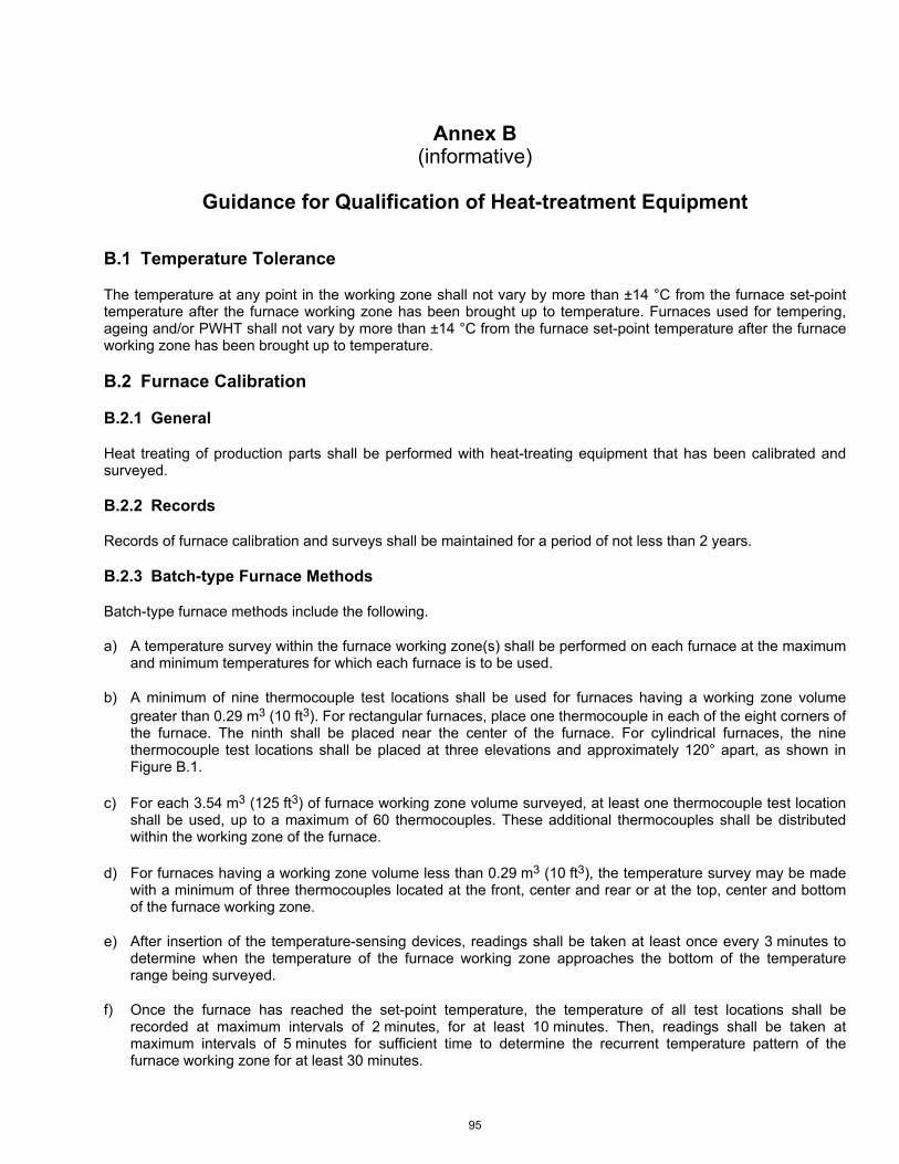
95
Annex B (informative)
Guidance for Qualification of Heat-treatment Equipment
B.1 Temperature Tolerance
The temperature at any point in the working zone shall not vary by more than ±14 °C from the furnace set-point temperature after the furnace working zone has been brought up to temperature. Furnaces used for tempering, ageing and/or PWHT shall not vary by more than ±14 °C from the furnace set-point temperature after the furnace working zone has been brought up to temperature.
B.2 Furnace Calibration
B.2.1 General
Heat treating of production parts shall be performed with heat-treating equipment that has been calibrated and surveyed.
B.2.2 Records
Records of furnace calibration and surveys shall be maintained for a period of not less than 2 years.
B.2.3 Batch-type Furnace Methods
Batch-type furnace methods include the following.
a) A temperature survey within the furnace working zone(s) shall be performed on each furnace at the maximum and minimum temperatures for which each furnace is to be used.
b) A minimum of nine thermocouple test locations shall be used for furnaces having a working zone volume greater than 0.29 m3 (10 ft3). For rectangular furnaces, place one thermocouple in each of the eight corners of the furnace. The ninth shall be placed near the center of the furnace. For cylindrical furnaces, the nine thermocouple test locations shall be placed at three elevations and approximately 120° apart, as shown in Figure B.1.
c) For each 3.54 m3 (125 ft3) of furnace working zone volume surveyed, at least one thermocouple test location shall be used, up to a maximum of 60 thermocouples. These additional thermocouples shall be distributed within the working zone of the furnace.
d) For furnaces having a working zone volume less than 0.29 m3 (10 ft3), the temperature survey may be made with a minimum of three thermocouples located at the front, center and rear or at the top, center and bottom of the furnace working zone.
e) After insertion of the temperature-sensing devices, readings shall be taken at least once every 3 minutes to determine when the temperature of the furnace working zone approaches the bottom of the temperature range being surveyed.
f) Once the furnace has reached the set-point temperature, the temperature of all test locations shall be recorded at maximum intervals of 2 minutes, for at least 10 minutes. Then, readings shall be taken at maximum intervals of 5 minutes for sufficient time to determine the recurrent temperature pattern of the furnace working zone for at least 30 minutes.
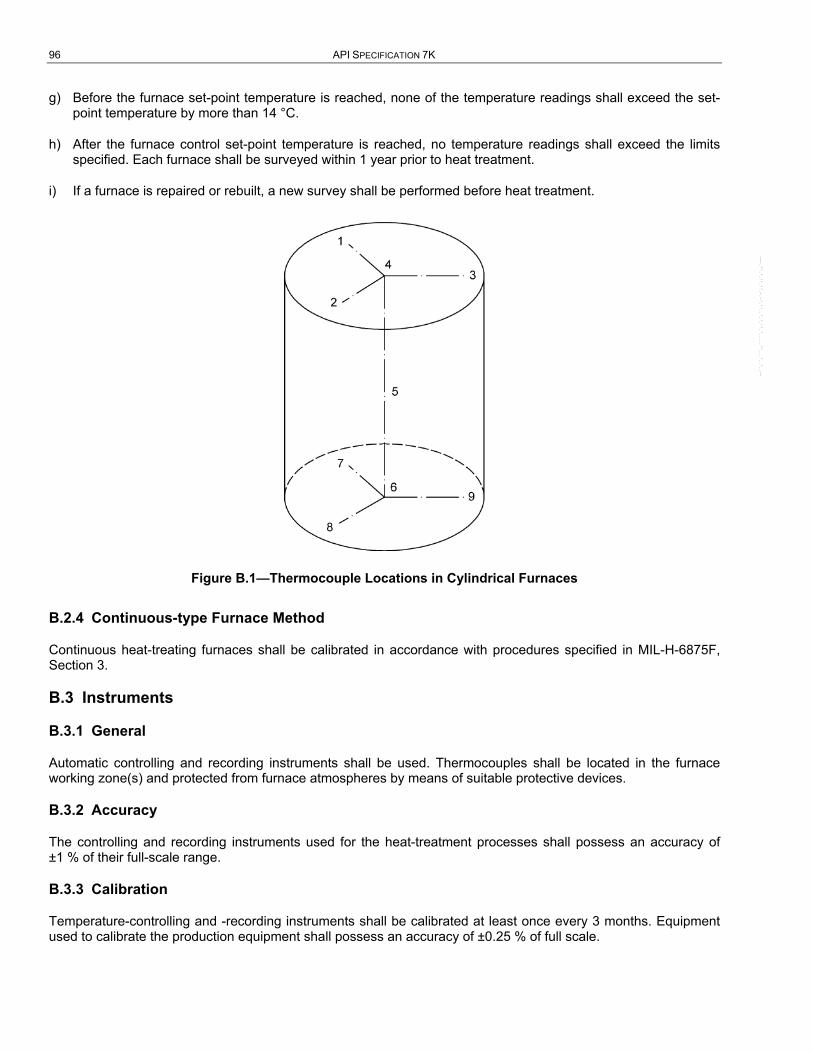
96 API SPECIFICATION 7K
g) Before the furnace set-point temperature is reached, none of the temperature readings shall exceed the set-point temperature by more than 14 °C.
h) After the furnace control set-point temperature is reached, no temperature readings shall exceed the limits specified. Each furnace shall be surveyed within 1 year prior to heat treatment.
i) If a furnace is repaired or rebuilt, a new survey shall be performed before heat treatment.
Figure B.1—Thermocouple Locations in Cylindrical Furnaces
B.2.4 Continuous-type Furnace Method
Continuous heat-treating furnaces shall be calibrated in accordance with procedures specified in MIL-H-6875F, Section 3.
B.3 Instruments
B.3.1 General
Automatic controlling and recording instruments shall be used. Thermocouples shall be located in the furnace working zone(s) and protected from furnace atmospheres by means of suitable protective devices.
B.3.2 Accuracy
The controlling and recording instruments used for the heat-treatment processes shall possess an accuracy of ±1 % of their full-scale range.
B.3.3 Calibration
Temperature-controlling and -recording instruments shall be calibrated at least once every 3 months. Equipment used to calibrate the production equipment shall possess an accuracy of ±0.25 % of full scale.
--``,``,```,,`````,`,,`,`,``,,`,-`-`,,`,,`,`,,`---

97
Annex C (informative)
Recommended Piston Mud-pump Nomenclature and Maintenance
C.1 Piston Mud-pump Nomenclature
The intent of this annex is to standardize nomenclature for principal parts of mud pumps, excluding a relatively small number of associated parts. This will provide a common language for the industry, particularly valuable for communication.
C.2 Old Designs
This language is to be used for old pumps as well as newly designed pumps, even though the manufacturer’s literature might not be consistent with this specification. Manufacturers are expected to comply with this specification on newly designed pumps. For old designs, their literature should be made to comply when it is opportune to do so. In communications between user and manufacturer, the part number should be used as positive identification where nomenclature inconsistencies occur.
C.3 Types
This nomenclature is applicable to duplex and triplex power-piston mud pumps.
C.4 Designation
Power end (see Table C.1, Figure C.1, Figure C.2 and Figure C.3) and fluid end parts (see Table C.2, Figure C.4, Table C.3 and Figure C.5) are grouped in separate categories. Right- and left-hand parts for all groups are determined by the same rule. The rule is: when standing at the power end and looking over the power end toward the fluid end, those parts to the right of the centerline are designated as right-hand when needed to differentiate from other like parts; and, similarly, those to the left are designated as left-hand. For triplex pumps, those parts on the centerline needing differentiation from like parts are designated center.
--``,``,```,,`````,`,,`,`,``,,`,-`-`,,`,,`,`,,`---
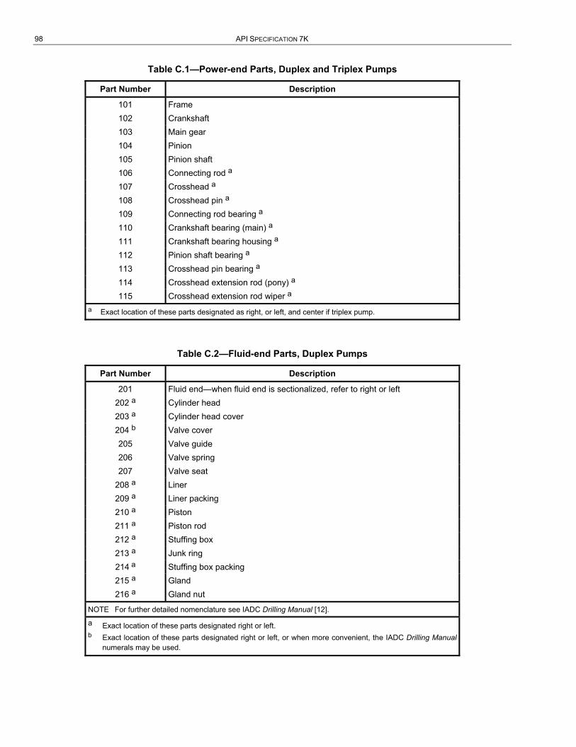
98 API SPECIFICATION 7K
Table C.1—Power-end Parts, Duplex and Triplex Pumps
Part Number Description
101 Frame 102 Crankshaft 103 Main gear 104 Pinion 105 Pinion shaft 106 Connecting rod a 107 Crosshead a 108 Crosshead pin a 109 Connecting rod bearing a 110 Crankshaft bearing (main) a 111 Crankshaft bearing housing a 112 Pinion shaft bearing a 113 Crosshead pin bearing a 114 Crosshead extension rod (pony) a 115 Crosshead extension rod wiper a
a Exact location of these parts designated as right, or left, and center if triplex pump.
Table C.2—Fluid-end Parts, Duplex Pumps
Part Number Description
201 Fluid end—when fluid end is sectionalized, refer to right or left 202 a Cylinder head 203 a Cylinder head cover 204 b Valve cover 205 Valve guide 206 Valve spring 207 Valve seat
208 a Liner 209 a Liner packing 210 a Piston 211 a Piston rod 212 a Stuffing box 213 a Junk ring 214 a Stuffing box packing 215 a Gland 216 a Gland nut
NOTE For further detailed nomenclature see IADC Drilling Manual [12].
a Exact location of these parts designated right or left. b Exact location of these parts designated right or left, or when more convenient, the IADC Drilling Manual
numerals may be used.
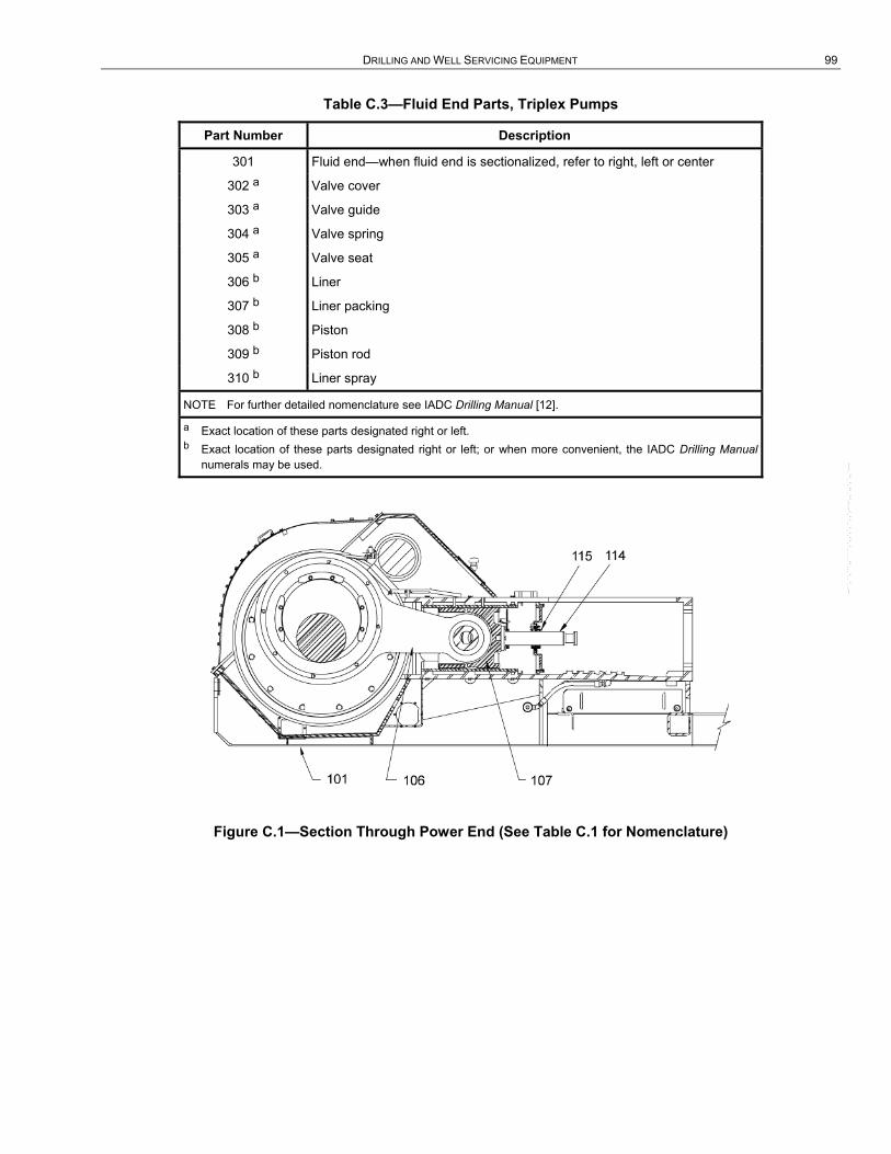
DRILLING AND WELL SERVICING EQUIPMENT 99
Table C.3—Fluid End Parts, Triplex Pumps
Part Number Description
301 Fluid end—when fluid end is sectionalized, refer to right, left or center
302 a Valve cover
303 a Valve guide
304 a Valve spring
305 a Valve seat
306 b Liner
307 b Liner packing
308 b Piston
309 b Piston rod
310 b Liner spray
NOTE For further detailed nomenclature see IADC Drilling Manual [12].
a Exact location of these parts designated right or left. b Exact location of these parts designated right or left; or when more convenient, the IADC Drilling Manual
numerals may be used.
Figure C.1—Section Through Power End (See Table C.1 for Nomenclature) --``,``,```,,`````,`,,`,`,``,,`,-`-`,,`,,`,`,,`---

100 API SPECIFICATION 7K
Figure C.2—Section Through Crankshaft (See Table C.1 for Nomenclature)
Figure C.3—Section Through Pinion Shaft and Crosshead (See Table C.1 for Nomenclature)
--``,``,```,,`````,`,,`,`,``,,`,-`-`,,`,,`,`,,`---

DRILLING AND WELL SERVICING EQUIPMENT 101
Figure C.4—Fluid End of Duplex Double-acting Mud Pump (See Table C.2 for Nomenclature)
Figure C.5—Fluid End of Triplex Single-acting Mud Pump (See Table D.3 for Nomenclature)
--``,``,```,,`````,`,,`,`,``,,`,-`-`,,`,,`,`,,`---
102
Annex D (informative)
Use of the API Monogram by Licensees
D.1 Scope
The API Monogram Program allows an API licensee to apply the API Monogram to products. The API Monogram Program delivers significant value to the international oil and gas industry by linking the verification of an organization's quality management system with the demonstrated ability to meet specific product specification requirements. The use of the Monogram on products constitutes a representation and warranty by the licensee to purchasers of the products that, on the date indicated, the products were produced in accordance with a verified quality management system and in accordance with an API product specification.
When used in conjunction with the requirements of the API License Agreement, API Q1, in its entirety, defines the requirements for those organizations who wish to voluntarily obtain an API license to provide API monogrammed products in accordance with an API product specification.
API Monogram Program licenses are issued only after an on-site audit has verified that the licensee conforms to the requirements described in API Q1 in total, and the requirements of an API product specification. Customers/users are requested to report to API all problems with API monogrammed products. The effectiveness of the API Monogram Program can be strengthened by customers/users reporting problems encountered with API monogrammed products. A nonconformance may be reported using the API Nonconformance Reporting System available at https://ncr.api.org. API solicits information on new product that is found to be nonconforming with API-specified requirements, as well as field failures (or malfunctions), which are judged to be caused by either specification deficiencies or nonconformities with API-specified requirements.
This annex sets forth the API Monogram Program requirements necessary for a supplier to consistently produce products in accordance with API-specified requirements. For information on becoming an API Monogram licensee, please contact API, Certification Programs, 1220 L Street, N. W., Washington, D.C. 20005 or call 202-962-4791 or by email at [email protected].
D.2 References
In addition to the referenced standards listed earlier in this document, this annex references the following standard:
API Specification Q1.
For licensees under the Monogram Program, the latest version of this document shall be used. The requirements identified therein are mandatory.
D.3 API Monogram Program: Licensee Responsibilities
D.3.1 Maintaining a License to Use the API Monogram
For all organizations desiring to acquire and maintain a license to use the API Monogram, conformance with the following shall be required at all times:
a) the quality management system requirements of API Q1;
b) the API Monogram Program requirements of API Q1, Annex A;

DRILLING AND WELL SERVICING EQUIPMENT 103
c) the requirements contained in the API product specification(s) for which the organization desires to be licensed;
d) the requirements contained in the API Monogram Program License Agreement.
D.3.2 Monogrammed Product Conformance with API Q1
When an API-licensed organization is providing an API monogrammed product, conformance with API-specified requirements, described in API Q1, including Annex A, is required.
D.3.3 Application of the API Monogram
Each licensee shall control the application of the API Monogram in accordance with the following.
a) Each licensee shall develop and maintain an API Monogram marking procedure that documents the marking/monogramming requirements specified by the API product specification to be used for application of the API Monogram by the licensee. The marking procedure shall define the location(s) where the licensee shall apply the API Monogram and require that the licensee's license number and date of manufacture be marked on monogrammed products in conjunction with the API Monogram. At a minimum, the date of manufacture shall be two digits representing the month and two digits representing the year (e.g. 05-07 for May 2007) unless otherwise stipulated in the applicable API product specification. Where there are no API product specification marking requirements, the licensee shall define the location(s) where this information is applied.
b) The API Monogram may be applied at any time appropriate during the production process but shall be removed in accordance with the licensee’s API Monogram marking procedure if the product is subsequently found to be nonconforming with API-specified requirements. Products that do not conform to API-specified requirements shall not bear the API Monogram.
c) Only an API licensee may apply the API Monogram and its license number to API monogrammable products. For certain manufacturing processes or types of products, alternative API Monogram marking procedures may be acceptable. The current API requirements for Monogram marking are detailed in the API Policy Document, Monogram Marking Requirements, available on the API Monogram Program website at http://www.api.org/certifications/monogram/.
d) The API Monogram shall be applied at the licensed facility.
e) The authority responsible for applying and removing the API Monogram shall be defined in the licensee’s API Monogram marking procedure.
D.3.4 Records
Records required by API product specifications shall be retained for a minimum of five years or for the period of time specified within the product specification if greater than five years. Records specified to demonstrate achievement of the effective operation of the quality system shall be maintained for a minimum of five years.
D.3.5 Quality Program Changes
Any proposed change to the licensee’s quality program to a degree requiring changes to the quality manual shall be submitted to API for acceptance prior to incorporation into the licensee's quality program.
D.3.6 Use of the API Monogram in Advertising
Licensee shall not use the API Monogram on letterheads or in any advertising (including company-sponsored web sites) without an express statement of fact describing the scope of licensee’s authorization (license number). The licensee should contact API for guidance on the use of the API Monogram other than on products.
--``,``,```,,`````,`,,`,`,``,,`,-`-`,,`,,`,`,,`---

104 API SPECIFICATION 7K
D.4 Marking Requirements for Products
D.4.1 General
These marking requirements apply only to those API licensees wishing to mark their products with the API Monogram.
D.4.2 Product Specification Identification
Manufacturers shall mark equipment with the information identified in Section 10, as a minimum, including “API Spec 7K.”
D.4.3 Units
As a minimum, equipment should be marked with U.S. customary (USC) units. Use of dual units [metric (SI) units and USC units] is acceptable.
D.4.4 License Number
The API Monogram license number shall not be used unless it is marked in conjunction with the API Monogram.
D.4.5 API Monogram Program: API Responsibilities
The API shall maintain records of reported problems encountered with API monogrammed products. Documented cases of nonconformity with API-specified requirements may be reason for an audit of the licensee involved, (also known as audit for “cause”).
Documented cases of specification deficiencies shall be reported, without reference to licensees, customers or users, to API Subcommittee 18 (Quality) and to the applicable API Standards Subcommittee for corrective actions.
--``,``,```,,`````,`,,`,`,``,,`,-`-`,,`,,`,`,,`---

105
Bibliography
[1] ISO/TR 9769 14, Steel and iron—Review of available methods of analysis
[2] ISO 10012-1, Quality assurance requirements for measuring equipment—Part 1: Metrological confirmation system for measuring equipment
[3] AGMA 6010-F97 15, Standard for Spur, Helical, Herringbone, and Bevel Enclosed Drives
[4] API Specification 7, Specification for Rotary Drill Stem Elements
[5] API Recommended Practice 7L, First Edition, Inspection, Maintenance, Repair, and Remanufacture of Drilling Equipment
[6] API Specification 16C, Choke and Kill Systems
[7] API Recommended Practice 17B, Recommended Practice for Flexible Pipe
[8] ASTM A488 16, Standard Practice for Steel Castings, Welding, Qualifications of Procedures and Personnel
[9] ASTM A668, Standard Specification for Steel Forgings, Carbon and Alloy, for General Industrial Use
[10] ASTM A781, Standard Specification for Castings, Steel and Alloy, Common Requirements for General Industrial Use
[11] ASTM A788, Standard Specification for Steel Forgings, General Requirements
[12] DOD MIL-STD-120 17, Gauge Inspection
[13] FEM 18, Rules for the design of hoisting appliances
[14] IADC 19, Drilling Manual
[15] DOD MIL-H-6875F, Heat-treatment of Steel Raw Materials, Aircraft Practice Process
[16] SAE AS 1260 20, Equivalent Sections of Certain Shapes to Round Bars
14 International Organization for Standardization, 1, ch. de la Voie-Creuse, Case postale 56, CH-1211, Geneva 20, Switzerland, www.iso.org.
15 American Gear Manufacturers Association, 500 Montgomery Street, Suite 350, Alexandria, Virginia 22314, www.agma.org. 16 ASTM International, 100 Barr Harbor Drive, West Conshohocken, Pennsylvania 19428, www.astm.org. 17 Department of Defense, 1400 Defense Pentagon, Washington DC 20301-1400, www.defenselink.mil. 18 Fédération Européenne de la Manutention, 39-41, rue Louis Blanc, 92400 Courbevoie, 92038 Paris, La Défense Cedex,
France, www.fem-eur.com. 19 International Association of Drilling Contractors, P.O. Box 4287, Houston, Texas 77210, www.iadc.org. 20
Society of Automotive Engineers, 400 Commonwealth Drive, Warrendale, Pennsylvania 15096-0001, www.sae.org.
--``,``,```,,`````,`,,`,`,``,,`,-`-`,,`,,`,`,,`---

--``,``,```,,`````,`,,`,`,``,,`,-`-`,,`,,`,`,,`---

Invoice To (� Check here if same as “Ship To”)
Name:
Title:
Company:
Department:
Address:
City: State/Province:
Zip/Postal Code: Country:
Telephone:
Fax:
Email:
� Payment Enclosed � P.O. No. (Enclose Copy)
� Charge My IHS Account No.
� VISA � MasterCard � American Express� Diners Club � Discover
Credit Card No.:
Print Name (As It Appears on Card):
Expiration Date:
Signature:
Quantity Title Total
Subtotal
Applicable Sales Tax (see below)
Rush Shipping Fee (see below)
Shipping and Handling (see below)
Total (in U.S. Dollars)
� To be placed on Standing Order for future editions of thispublication, place a check mark in the SO column and sign here:
Date:
SO� Unit Price
� API Member (Check if Yes)
Ship To (UPS will not deliver to a P.O. Box)Name:
Title:
Company:
Department:
Address:
City: State/Province:
Zip/Postal Code: Country:
Telephone:
Fax:
Email:
Mail Orders – Payment by check or money order in U.S. dollars is required except for established accounts. State and local taxes, $10 processing fee, and 5% shipping must beadded. Send mail orders to: API Publications, IHS, 15 Inverness Way East, c/o Retail Sales, Englewood, CO 80112-5776, USA.Purchase Orders – Purchase orders are accepted from established accounts. Invoice will include actual freight cost, a $10 processing fee, plus state and local taxes.Telephone Orders – If ordering by telephone, a $10 processing fee and actual freight costs will be added to the order.Sales Tax – All U.S. purchases must include applicable state and local sales tax. Customers claiming tax-exempt status must provide IHS with a copy of their exemption certificate.Shipping (U.S. Orders) – Orders shipped within the U.S. are sent via traceable means. Most orders are shipped the same day. Subscription updates are sent by First-Class Mail.Other options, including next-day service, air service, and fax transmission are available at additional cost. Call 1-800-854-7179 for more information.
Shipping (International Orders) – Standard international shipping is by air express courier service. Subscription updates are sent by World Mail. Normal delivery is 3-4 days from shipping date.
Rush Shipping Fee – Next Day Delivery orders charge is $20 in addition to the carrier charges. Next Day Delivery orders must be placed by 2:00 p.m. MST to ensure overnight delivery.Returns – All returns must be pre-approved by calling the IHS Customer Service Department at 1-800-624-3974 for information and assistance. There may be a 15% restockingfee. Special order items, electronic documents, and age-dated materials are non-returnable.
Pricing and availability subject to change without notice.
2010 PUBLICATIONS ORDER FORM
Effective January 1, 2010. API Members receive a 30% discount where applicable. The member discount does not apply to purchases madefor the purpose of resale or for incorporation into commercial products, training courses, workshops, or other commercial enterprises.
Ordering Information Online: www.api.org/pubsPhone: 1-800-854-7179 (Toll-free in the U.S. and Canada) | (+1) 303-397-7956 (Local and International)Fax: (+1) 303-397-2740

THERE’S MOREWHERE THIS CAME FROM.
API Monogram® Licensing ProgramSales: (+1) 713-964-2662Service: (+1) 202-962-4791Fax: (+1) 202-682-8070Email: [email protected]: www.api.org/monogram
API Quality Registrar (APIQR®)• ISO 9001•ISO/TS 29001•ISO 14001•OHSAS 18001•API Spec Q1® •API QualityPlus®•Dual Registration Sales: (+1) 713-964-2662Service: (+1) 202-962-4791Fax: (+1) 202-682-8070Email: [email protected]: www.api.org/apiqr
API Individual Certification Programs (ICP®) Sales: (+1) 713-964-2662Service: (+1) 202-682-8064Fax: (+1) 202-682-8348Email: [email protected]: www.api.org/icp
API Engine Oil Licensing andCertification System (EOLCS)Sales: (+1) 713-964-2662Service: (+1) 202-682-8516Fax: (+1) 202-962-4739Email: [email protected]: www.api.org/eolcs
API Training Provider Certification Program (API TPCP™) Sales: (+1) 713-964-2662Service: (+1) 202-682-8075Fax: (+1) 202-682-8070Email: [email protected]: www.api.org/tpcp
API Perforator Design Registration ProgramSales: (+1) 713-964-2662Service: (+1) 202-682-8490Fax: (+1) 202-682-8070Email: [email protected]: www.api.org/perforators
API Credit Exchange (ACE™)Service: (+1) 202-682-8192Fax: (+1) 202-682-8070Email: [email protected]: www.api.org/ace
API Diesel Exhaust Fluid Certification Program Phone: (+1) 202-682-8516Fax: (+1) 202-962-4739Email: [email protected]: www.apidef.org
API WorkSafe™Sales: (+1) 713-964-2662 Service: (+1) 202-682-8469Fax: (+1) 202-682-8348Email: [email protected]: www.api.org/worksafe
API-UPhone: (+1) 202-682-8053Fax: (+1) 202-682-8070Email: [email protected]: www.api-u.org
API Data™Phone: (+1) 202-682-8499Fax: (+1) 202-962-4730Email: [email protected]: www.APIDataNow.org
API Publications Online: www.api.org/pubsPhone: 1-800-854-7179
(Toll-free: U.S./Canada)(+1) 303-397-7956 (Local/International)
Fax: (+1) 303-397-2740
API Standards Phone: (+1) 202-682-8148Fax: (+1) 202-962-4797Email: standards.orgWeb: www.api.org/standards
Request a Quotation:www.api.org/quote

--``,``,```,,`````,`,,`,`,``,,`,-`-`,,`,,`,`,,`---

Product No. G07K05
--``,``,```,,`````,`,,`,`,``,,`,-`-`,,`,,`,`,,`---


![+YPSSPUN >VYRV]LY >LSS:LY]PJPUN9PNZ7 Drilling, Workover & Well Servicing Rigs Mast Free-standing API 4F hydraulically raised and telescoping mast: • Outriggers • Hollow structural](https://static.fdocuments.us/doc/165x107/5e7aa194649c7b681f46b7c2/ypsspun-vyrvly-lsslypjpun9pnz-7-drilling-workover-well-servicing.jpg)