COMPREHENSIVE PROJECT REPORT Training...
55
COMPREHENSIVE PROJECT REPORT FOR PROPOSED Training Center - TVS Institute for Quality and Leadership At Survey Nos. 63, 64/1, 64/2, 64/3, 65/1, 65/2, 66, 67, 68, 69/1, 69/2, 69/3, 69/4, 70/1,70/2, 71/3,75, 76, 77, 78, 79, 80/1, 80/2, 80/3, 81/1 to 81/7, 82/1, 82/2A,82/2B, 82/3, 83, 173, 174, 176 & 177 of Thattanahalli village, Kasaba hobli, Anekal taluk, Bengaluru. Submitted By M/s TVS Motor Company Ltd., TVS Institute for Quality and Leadership, Thattanahalli village, Kasaba Hobli, Anekal Taluk, Bengaluru. Submitted to State Environment Impact Assessment Authority, Karnataka. ENVIRONMENTAL CONSULTANTS M/s. AQUA TECH ENVIRO ENGINEERS, # 3391, 6 th Main, 3 rd Cross, RPC Layout, Vijayanagara II Stage, Bangalore – 560 040. Tele Phone: 080 - 23141679 Fax: 080 – 2314816
Transcript of COMPREHENSIVE PROJECT REPORT Training...

COMPREHENSIVE PROJECT REPORT FOR PROPOSED
Training Center - TVS Institute for Quality and Leadership
At
Survey Nos. 63, 64/1, 64/2, 64/3, 65/1, 65/2, 66, 67, 68, 69/1, 69/2, 69/3, 69/4, 70/1,70/2, 71/3,75, 76,
77, 78, 79, 80/1, 80/2, 80/3, 81/1 to 81/7, 82/1, 82/2A,82/2B, 82/3, 83, 173, 174, 176 & 177 of
Thattanahalli village, Kasaba hobli, Anekal taluk, Bengaluru.
Submitted By
M/s TVS Motor Company Ltd., TVS Institute for Quality and Leadership,
Thattanahalli village, Kasaba Hobli, Anekal Taluk, Bengaluru.
Submitted to
State Environment Impact Assessment Authority, Karnataka.
ENVIRONMENTAL CONSULTANTS
M/s. AQUA TECH ENVIRO ENGINEERS, # 3391, 6th Main, 3rd Cross, RPC Layout,
Vijayanagara II Stage, Bangalore – 560 040. Tele Phone: 080 - 23141679
Fax: 080 – 2314816
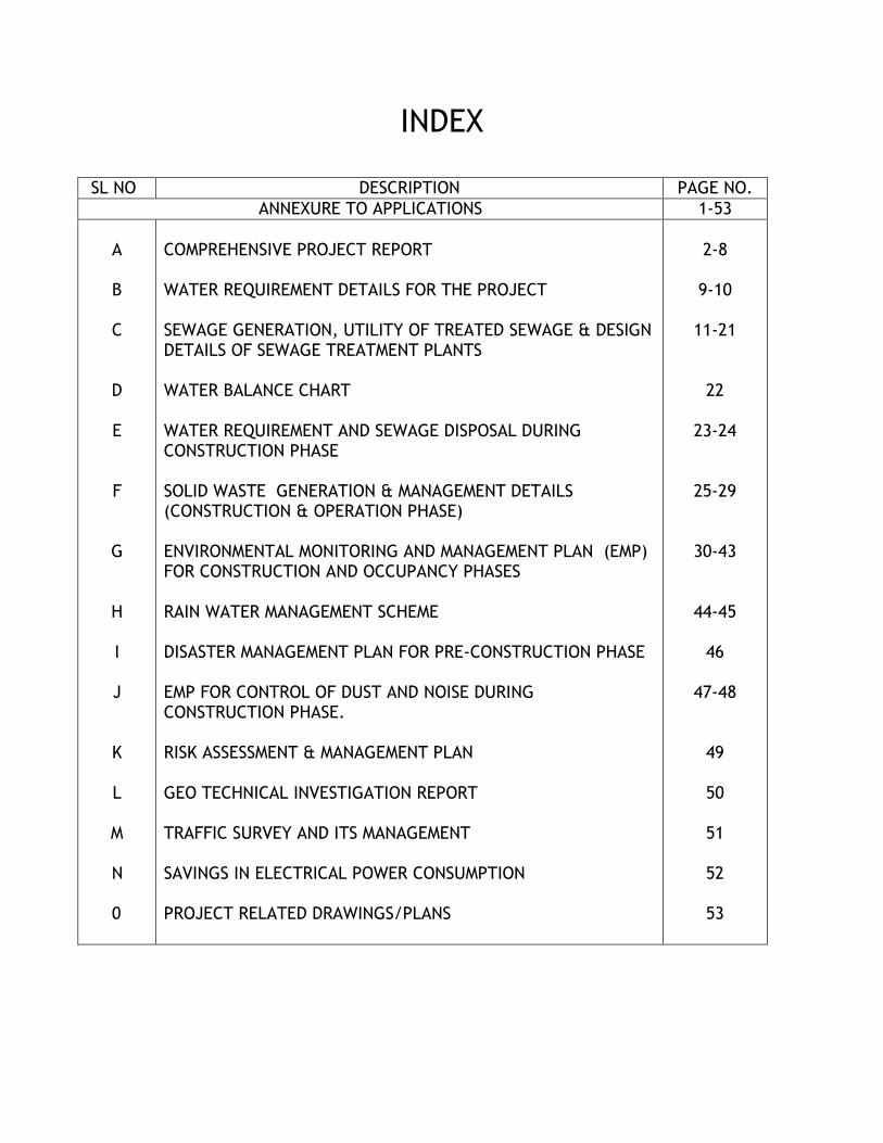
INDEX
SL NO DESCRIPTION PAGE NO.
ANNEXURE TO APPLICATIONS 1-53
A B C
D E F
G
H I J K L
M
N 0
COMPREHENSIVE PROJECT REPORT WATER REQUIREMENT DETAILS FOR THE PROJECT SEWAGE GENERATION, UTILITY OF TREATED SEWAGE & DESIGN DETAILS OF SEWAGE TREATMENT PLANTS WATER BALANCE CHART WATER REQUIREMENT AND SEWAGE DISPOSAL DURING CONSTRUCTION PHASE SOLID WASTE GENERATION & MANAGEMENT DETAILS (CONSTRUCTION & OPERATION PHASE) ENVIRONMENTAL MONITORING AND MANAGEMENT PLAN (EMP) FOR CONSTRUCTION AND OCCUPANCY PHASES RAIN WATER MANAGEMENT SCHEME DISASTER MANAGEMENT PLAN FOR PRE-CONSTRUCTION PHASE EMP FOR CONTROL OF DUST AND NOISE DURING CONSTRUCTION PHASE. RISK ASSESSMENT & MANAGEMENT PLAN GEO TECHNICAL INVESTIGATION REPORT TRAFFIC SURVEY AND ITS MANAGEMENT SAVINGS IN ELECTRICAL POWER CONSUMPTION PROJECT RELATED DRAWINGS/PLANS
2-8
9-10
11-21
22
23-24
25-29
30-43
44-45
46
47-48
49
50
51
52
53
Project Report M/s. TVS Motor Company Limited
ANNEXURE TO APPLICATIONS 1
Annexure & Details to Application in
Form 1 and Form 1A

Project Report M/s. TVS Motor Company Limited
ANNEXURE TO APPLICATIONS 2
ANNEXURE – A
COMPREHENSIVE PROJECT REPORT

Project Report M/s. TVS Motor Company Limited
ANNEXURE TO APPLICATIONS 3
PROJECT AT GLANCE
PROPOSED PROJECT Training Center - TVS Institute for Quality and
Leadership
LOCATION Survey Nos. 63, 64/1, 64/2, 64/3, 65/1, 65/2, 66, 67, 68, 69/1, 69/2, 69/3, 69/4, 70/1,70/2, 71/3,75, 76, 77, 78, 79, 80/1, 80/2, 80/3, 81/1 to 81/7, 82/1, 82/2A, 82/2B, 82/3, 83, 173, 174, 176 & 177 of Thattanahalli village, Kasaba hobli, Anekal taluk, Bengaluru.
TOTAL PLOT AREA 2,99,468 sq m (74 Acres)
TOTAL BUILT UP AREA 52,721 sq m
TOTAL COST OF PROJECT Rs. 40 Crores
NO OF FLOOR PROPOSED Presently few buildings are constructed and are in operation.
1) Existing Buildings: a) Activity: Institute b) Built up area: 4,217 sq m c) Number of blocks: 17 blocks d) Present Status: Under Operation
2) Proposed Building: a) Activity: Institute b) Additional Built up area: 48,504 sq m c) Number of blocks: 23 Block
3) Total project: a) Total built up area: 52,721 sq m b) Number of blocks: 40
WATER SUPPLY The water required for the project will be drawn from
the existing Borewells.
PROPOSED SANITATION Under Ground Sanitary System Facility for conveying
the wastewater to the Proposed Sewage Treatment
Plant(STP).
SOLID WASTE MANAGEMENT Collection and Segregation at source of generation and
the Organic waste will be treated in Organic Converter
and the Inorganic Waste will be sent for recycling.
AIR POLLUTION/ NOISE
GENERATION SOURCE
1 x 320 KVA and 1 x 62.5 KVA capacity DG sets are in
operation, they are provided with adequate stack and
acoustically housed and it is sufficient for the proposed
institute.
Project Report M/s. TVS Motor Company Limited
ANNEXURE TO APPLICATIONS 4
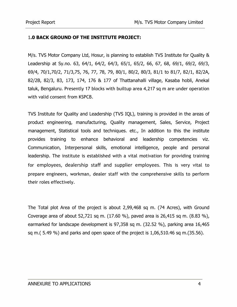
1.0 BACK GROUND OF THE INSTITUTE PROJECT:
M/s. TVS Motor Company Ltd, Hosur, is planning to establish TVS Institute for Quality &
Leadership at Sy.no. 63, 64/1, 64/2, 64/3, 65/1, 65/2, 66, 67, 68, 69/1, 69/2, 69/3,
69/4, 70/1,70/2, 71/3,75, 76, 77, 78, 79, 80/1, 80/2, 80/3, 81/1 to 81/7, 82/1, 82/2A,
82/2B, 82/3, 83, 173, 174, 176 & 177 of Thattanahalli village, Kasaba hobli, Anekal
taluk, Bengaluru. Presently 17 blocks with builtup area 4,217 sq m are under operation
with valid consent from KSPCB.
TVS Institute for Quality and Leadership (TVS IQL), training is provided in the areas of
product engineering, manufacturing, Quality management, Sales, Service, Project
management, Statistical tools and techniques. etc., In addition to this the institute
provides training to enhance behavioral and leadership competencies viz.
Communication, Interpersonal skills, emotional intelligence, people and personal
leadership. The institute is established with a vital motivation for providing training
for employees, dealership staff and supplier employees. This is very vital to
prepare engineers, workman, dealer staff with the comprehensive skills to perform
their roles effectively.
The Total plot Area of the project is about 2,99,468 sq m. (74 Acres), with Ground
Coverage area of about 52,721 sq m. (17.60 %), paved area is 26,415 sq m. (8.83 %),
earmarked for landscape development is 97,358 sq m. (32.52 %), parking area 16,465
sq m.( 5.49 %) and parks and open space of the project is 1,06,510.46 sq m.(35.56).
Project Report M/s. TVS Motor Company Limited
ANNEXURE TO APPLICATIONS 5
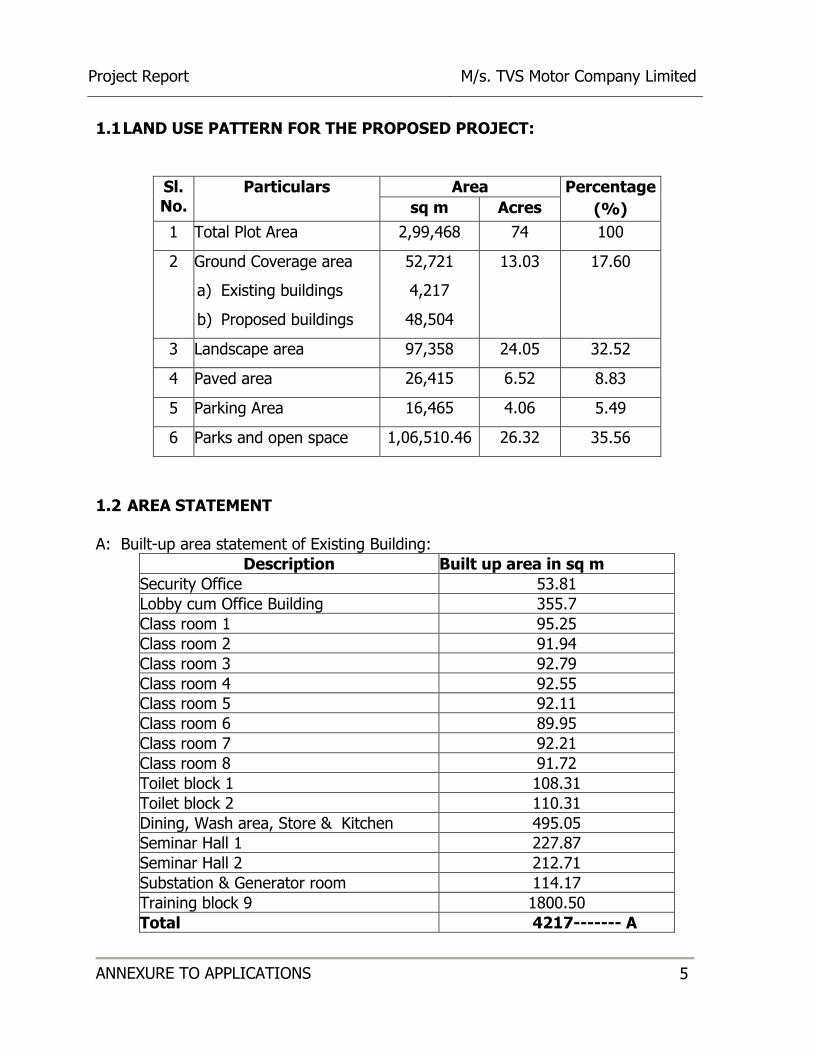
1.1 LAND USE PATTERN FOR THE PROPOSED PROJECT:
Sl. No.
Particulars Area Percentage
(%) sq m Acres
1 Total Plot Area 2,99,468 74 100
2 Ground Coverage area
a) Existing buildings
b) Proposed buildings
52,721
4,217
48,504
13.03 17.60
3 Landscape area 97,358 24.05 32.52
4 Paved area 26,415 6.52 8.83
5 Parking Area 16,465 4.06 5.49
6 Parks and open space 1,06,510.46 26.32 35.56
1.2 AREA STATEMENT
A: Built-up area statement of Existing Building:
Description Built up area in sq m
Security Office 53.81
Lobby cum Office Building 355.7
Class room 1 95.25
Class room 2 91.94
Class room 3 92.79
Class room 4 92.55
Class room 5 92.11
Class room 6 89.95
Class room 7 92.21
Class room 8 91.72
Toilet block 1 108.31
Toilet block 2 110.31
Dining, Wash area, Store & Kitchen 495.05
Seminar Hall 1 227.87
Seminar Hall 2 212.71
Substation & Generator room 114.17
Training block 9 1800.50
Total 4217------- A

Project Report M/s. TVS Motor Company Limited
ANNEXURE TO APPLICATIONS 6
B. Built-up area of Proposed Block
Description Built up area in sq m
Product training centre 998.6
Break away zone 3 shed 262.1
Training block 1 1429.2
Training block 2 1232.7
Training block 3 894
Training block 4 754.5
Training block 5 310.7
Training block 6 784.4
Training block 7 792.9
Training block 8 853.2
Training block 10 3183.2
Dog kennal 45.1
Rest shed 1 2700
STP 1800
Rest Shed 2 2700
Training block 13 17500
Training block 14 2457
Estate Management 1800
Riding skill block 1500
Covered parking 1800
Training block 15 1833
Training Block 16 2538
Canteen block 335.4
Sub total 48504 -----B
Total (A+B) 52721.00
C. PARKING STATEMENT :
Sl. No.
Description Parking Space Proposed
1 Car parking 80
2 Bus parking 55
3 Two wheeler parking 10
Total 145
Project Report M/s. TVS Motor Company Limited
ANNEXURE TO APPLICATIONS 7
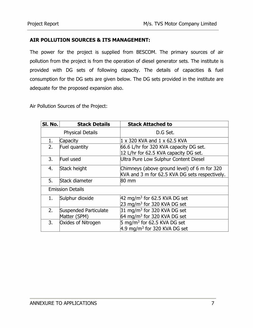
AIR POLLUTION SOURCES & ITS MANAGEMENT:
The power for the project is supplied from BESCOM. The primary sources of air
pollution from the project is from the operation of diesel generator sets. The institute is
provided with DG sets of following capacity. The details of capacities & fuel
consumption for the DG sets are given below. The DG sets provided in the institute are
adequate for the proposed expansion also.
Air Pollution Sources of the Project:
Sl. No. Stack Details Stack Attached to
Physical Details D.G Set.
1. Capacity 1 x 320 KVA and 1 x 62.5 KVA
2. Fuel quantity 66.6 L/hr for 320 KVA capacity DG set. 12 L/hr for 62.5 KVA capacity DG set.
3. Fuel used Ultra Pure Low Sulphur Content Diesel
4. Stack height Chimneys (above ground level) of 6 m for 320 KVA and 3 m for 62.5 KVA DG sets respectively.
5. Stack diameter 80 mm
Emission Details
1. Sulphur dioxide 42 mg/m3 for 62.5 KVA DG set 23 mg/m3 for 320 KVA DG set
2. Suspended Particulate Matter (SPM)
31 mg/m3 for 320 KVA DG set 64 mg/m3 for 320 KVA DG set
3. Oxides of Nitrogen 5 mg/m3 for 62.5 KVA DG set 4.9 mg/m3 for 320 KVA DG set
Project Report M/s. TVS Motor Company Limited
ANNEXURE TO APPLICATIONS 8
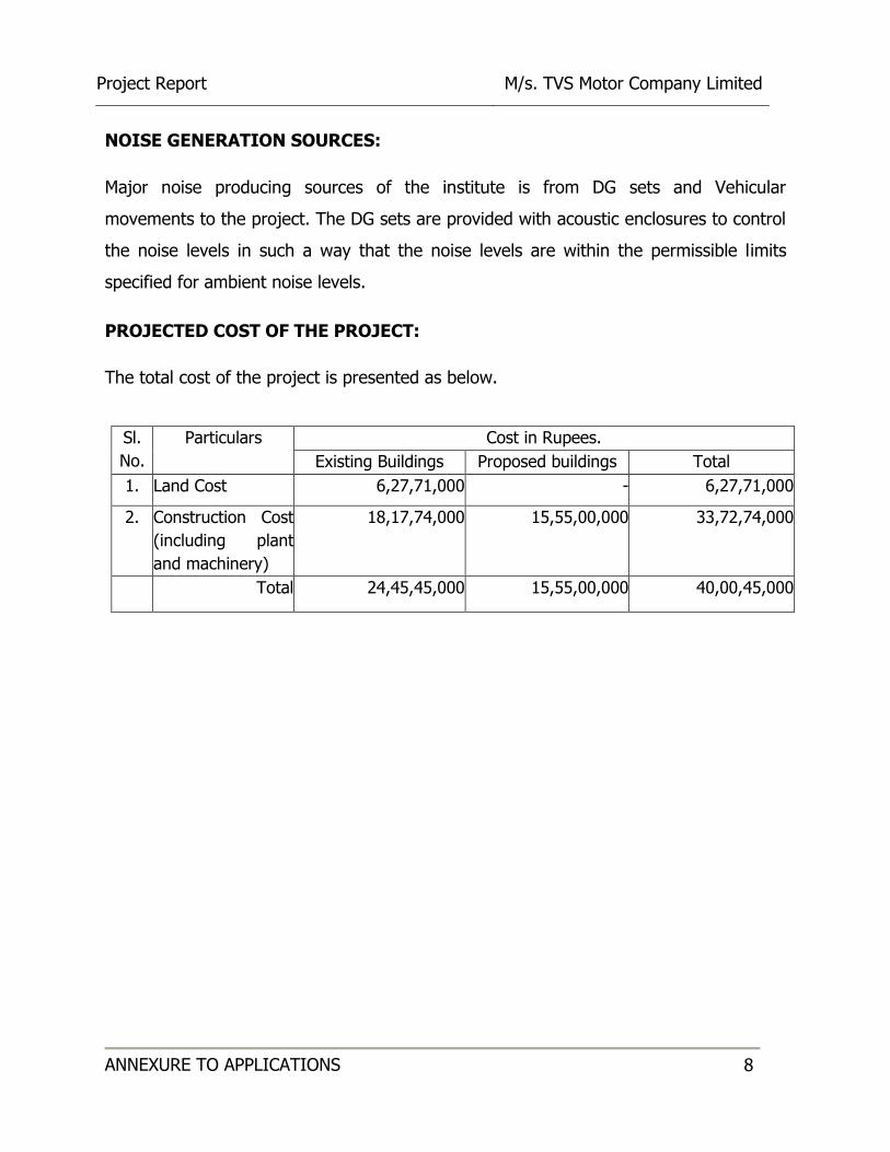
NOISE GENERATION SOURCES:
Major noise producing sources of the institute is from DG sets and Vehicular
movements to the project. The DG sets are provided with acoustic enclosures to control
the noise levels in such a way that the noise levels are within the permissible limits
specified for ambient noise levels.
PROJECTED COST OF THE PROJECT:
The total cost of the project is presented as below.
Sl.
No.
Particulars Cost in Rupees.
Existing Buildings Proposed buildings Total
1. Land Cost 6,27,71,000 - 6,27,71,000
2. Construction Cost
(including plant
and machinery)
18,17,74,000 15,55,00,000 33,72,74,000
Total 24,45,45,000 15,55,00,000 40,00,45,000
Project Report M/s. TVS Motor Company Limited
ANNEXURE TO APPLICATIONS 9
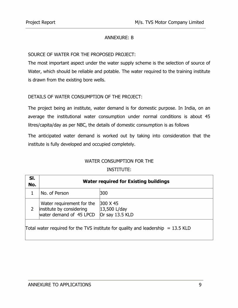
ANNEXURE: B
SOURCE OF WATER FOR THE PROPOSED PROJECT:
The most important aspect under the water supply scheme is the selection of source of
Water, which should be reliable and potable. The water required to the training institute
is drawn from the existing bore wells.
DETAILS OF WATER CONSUMPTION OF THE PROJECT:
The project being an institute, water demand is for domestic purpose. In India, on an
average the institutional water consumption under normal conditions is about 45
litres/capita/day as per NBC, the details of domestic consumption is as follows
The anticipated water demand is worked out by taking into consideration that the
institute is fully developed and occupied completely.
WATER CONSUMPTION FOR THE
INSTITUTE:
Sl.
No. Water required for Existing buildings
1 No. of Person 300
2 Water requirement for the institute by considering water demand of 45 LPCD
300 X 45 13,500 L/day Or say 13.5 KLD
Total water required for the TVS institute for quality and leadership = 13.5 KLD
Project Report M/s. TVS Motor Company Limited
ANNEXURE TO APPLICATIONS 10
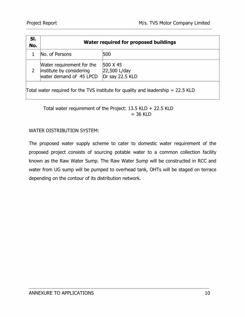
Sl.
No. Water required for proposed buildings
1 No. of Persons 500
2 Water requirement for the institute by considering water demand of 45 LPCD
500 X 45 22,500 L/day Or say 22.5 KLD
Total water required for the TVS institute for quality and leadership = 22.5 KLD
Total water requirement of the Project: 13.5 KLD + 22.5 KLD
= 36 KLD
WATER DISTRIBUTION SYSTEM:
The proposed water supply scheme to cater to domestic water requirement of the
proposed project consists of sourcing potable water to a common collection facility
known as the Raw Water Sump. The Raw Water Sump will be constructed in RCC and
water from UG sump will be pumped to overhead tank, OHTs will be staged on terrace
depending on the contour of its distribution network.
Project Report M/s. TVS Motor Company Limited
ANNEXURE TO APPLICATIONS 11
ANNEXURE: C
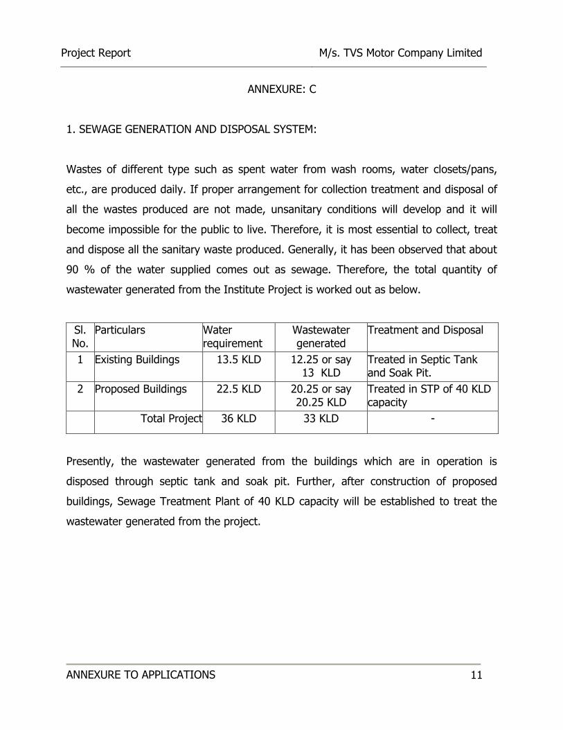
1. SEWAGE GENERATION AND DISPOSAL SYSTEM:
Wastes of different type such as spent water from wash rooms, water closets/pans,
etc., are produced daily. If proper arrangement for collection treatment and disposal of
all the wastes produced are not made, unsanitary conditions will develop and it will
become impossible for the public to live. Therefore, it is most essential to collect, treat
and dispose all the sanitary waste produced. Generally, it has been observed that about
90 % of the water supplied comes out as sewage. Therefore, the total quantity of
wastewater generated from the Institute Project is worked out as below.
Sl. No.
Particulars Water requirement
Wastewater generated
Treatment and Disposal
1 Existing Buildings 13.5 KLD 12.25 or say 13 KLD
Treated in Septic Tank and Soak Pit.
2 Proposed Buildings 22.5 KLD 20.25 or say 20.25 KLD
Treated in STP of 40 KLD capacity
Total Project 36 KLD 33 KLD -
Presently, the wastewater generated from the buildings which are in operation is
disposed through septic tank and soak pit. Further, after construction of proposed
buildings, Sewage Treatment Plant of 40 KLD capacity will be established to treat the
wastewater generated from the project.

Project Report M/s. TVS Motor Company Limited
ANNEXURE TO APPLICATIONS 12
TREATED SEWAGE DISPOSAL:
Presently, the sewage generated is disposed through Septic tank and soak pit. After
expansion of the project the wastewater generated will be treated in sewage treatment
plant (STP).
The quantity of treated sewage generated from the project is 33 KLD. The treated
sewage will be disposed as under:
a. Toilet Flushing:
Total contribution population from the institute is 800 Persons.
Toilet flushing water requirement in the institute at the rate of 15 LPCD
= 800 X 15 = 12,000 L/day or say 12 KLD
c. Remaining treated sewage of 21 KLD will be used for gardening (landscape will be
developed around the blocks at selected locations, trees will be planted in remaining
areas). Modern irrigation technologies and scientific methods will be followed for
irrigation in order to conserve water, apart from this native, indigenous and less water
consuming, drought resistant trees will be planted.
Project Report M/s. TVS Motor Company Limited
ANNEXURE TO APPLICATIONS 13
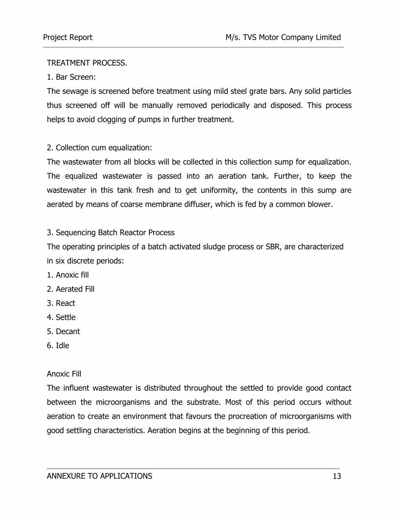
TREATMENT PROCESS.
1. Bar Screen:
The sewage is screened before treatment using mild steel grate bars. Any solid particles
thus screened off will be manually removed periodically and disposed. This process
helps to avoid clogging of pumps in further treatment.
2. Collection cum equalization:
The wastewater from all blocks will be collected in this collection sump for equalization.
The equalized wastewater is passed into an aeration tank. Further, to keep the
wastewater in this tank fresh and to get uniformity, the contents in this sump are
aerated by means of coarse membrane diffuser, which is fed by a common blower.
3. Sequencing Batch Reactor Process
The operating principles of a batch activated sludge process or SBR, are characterized
in six discrete periods:
1. Anoxic fill
2. Aerated Fill
3. React
4. Settle
5. Decant
6. Idle
Anoxic Fill
The influent wastewater is distributed throughout the settled to provide good contact
between the microorganisms and the substrate. Most of this period occurs without
aeration to create an environment that favours the procreation of microorganisms with
good settling characteristics. Aeration begins at the beginning of this period.
Project Report M/s. TVS Motor Company Limited
ANNEXURE TO APPLICATIONS 14
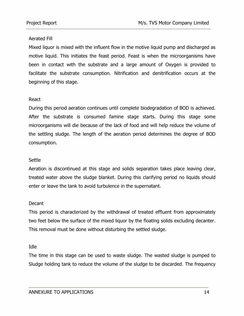
Aerated Fill
Mixed liquor is mixed with the influent flow in the motive liquid pump and discharged as
motive liquid. This initiates the feast period. Feast is when the microorganisms have
been in contact with the substrate and a large amount of Oxygen is provided to
facilitate the substrate consumption. Nitrification and denitrification occurs at the
beginning of this stage.
React
During this period aeration continues until complete biodegradation of BOD is achieved.
After the substrate is consumed famine stage starts. During this stage some
microorganisms will die because of the lack of food and will help reduce the volume of
the settling sludge. The length of the aeration period determines the degree of BOD
consumption.
Settle
Aeration is discontinued at this stage and solids separation takes place leaving clear,
treated water above the sludge blanket. During this clarifying period no liquids should
enter or leave the tank to avoid turbulence in the supernatant.
Decant
This period is characterized by the withdrawal of treated effluent from approximately
two feet below the surface of the mixed liquor by the floating solids excluding decanter.
This removal must be done without disturbing the settled sludge.
Idle
The time in this stage can be used to waste sludge. The wasted sludge is pumped to
Sludge holding tank to reduce the volume of the sludge to be discarded. The frequency
Project Report M/s. TVS Motor Company Limited
ANNEXURE TO APPLICATIONS 15
of sludge wasting ranges between once each cycle to once every two to three months
depending upon sludge volume index.
4. Sludge Drying Beds:
The excess sludge from SBR tank will be pumped to Sludge drying beds, where it is
subsequently dewatered by gravity. This dewatered and dried sludge can be used as
solid manure for agriculture and gardening.
5. Tertiary Treatment:
The treated water stored in the decant Water Tank will be pumped through Pressure
sand Filter and Activated Carbon Filter where the turbidity and residual BOD present
will be completely minimized. The treated water is then collected in the final collection
tank. Before reaching this tank, chlorine solution is dosed in to this water stream, with
the help of a Dosing pump, to disinfect as well as to digest any residual organic
matters. The treated water so collected shall be pumped and used for gardening and
irrigation. Also, the same water shall be used for back washing of filters. The back wash
drain, filter rinse drain and the decanted water shall be pumped/drained back to the
equalization tank.
Project Report M/s. TVS Motor Company Limited
ANNEXURE TO APPLICATIONS 16
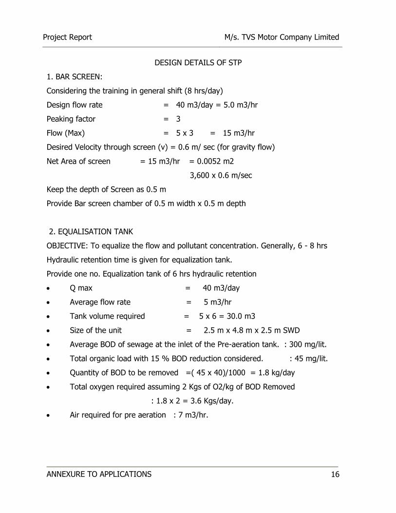
DESIGN DETAILS OF STP
1. BAR SCREEN:
Considering the training in general shift (8 hrs/day)
Design flow rate = 40 m3/day = 5.0 m3/hr
Peaking factor = 3
Flow (Max) = 5 x 3 = 15 m3/hr
Desired Velocity through screen (v) = 0.6 m/ sec (for gravity flow)
Net Area of screen = 15 m3/hr = 0.0052 m2
3,600 x 0.6 m/sec
Keep the depth of Screen as 0.5 m
Provide Bar screen chamber of 0.5 m width x 0.5 m depth
2. EQUALISATION TANK
OBJECTIVE: To equalize the flow and pollutant concentration. Generally, 6 - 8 hrs
Hydraulic retention time is given for equalization tank.
Provide one no. Equalization tank of 6 hrs hydraulic retention
Q max = 40 m3/day
Average flow rate = 5 m3/hr
Tank volume required = 5 x 6 = 30.0 m3
Size of the unit = 2.5 m x 4.8 m x 2.5 m SWD
Average BOD of sewage at the inlet of the Pre-aeration tank. : 300 mg/lit.
Total organic load with 15 % BOD reduction considered. : 45 mg/lit.
Quantity of BOD to be removed =( 45 x 40)/1000 = 1.8 kg/day
Total oxygen required assuming 2 Kgs of O2/kg of BOD Removed
: 1.8 x 2 = 3.6 Kgs/day.
Air required for pre aeration : 7 m3/hr.

Project Report M/s. TVS Motor Company Limited
ANNEXURE TO APPLICATIONS 17
3. RAW SEWAGE PUMP
Volume of sewage : 40 m3 / day ~ 10 m3/hr
4. SBR TANK
OBJECTIVE: To oxidize the organic content in the influent and to avoid any
objectionable odor. As chemical not used in the process is biological in nature, the DO
levels need to be high for maintaining the oxygen demand in the system.
Flow (design) = 40 m3/day
BOD = 255 mg/l
SBR tank volume = Q x BOD
F/M x MLSS
= 255 x 40
0.1 x 3500
SBR tank volume = 34.3 m3
Provide 30% for sludge accumulation
Total SBR tank volume provided = 44.6 m3
Assume SWD to be 3.5 m
Therefore plan area required = 44.6/3.5 = 12.7 m2
Size of Aeration Tank Required: 2.5 m x 5.0 m x 3.5 m SWD
DIFFUSED AERATION SYSTEM
Flow = 40 cum/day
Inlet BOD = 255 mg/l
Organic load = BOD X Flow rate
1000
Total organic load in the system: (255 X 40)/ 1000 = 10.2 Kgs/day
Total oxygen required assuming that 2 Kgs of O2/kg of BOD Removed
= 2 X 10.2 = 20.4 Kgs/day

Project Report M/s. TVS Motor Company Limited
ANNEXURE TO APPLICATIONS 18
Assume alpha =0.6 and β= 0.7
Consider oxygen transfer at 0.35 m depth = 20%
Density of Air = 1.2 Kg/m3
Percentage of Oxygen in Atmospheric air = 21%
Air required = 20.4
1.2 x 0.21 x 0.6 x 0.7 x 0.2
= 997 m3/day
= 42.0 m3/hr
5. DUAL MEDIA FILTER
OBJECTIVE: To filter the residual suspended solids from the clarified water.
Flow rate 40/4 = 10 m3/hr
Type of filter = Dual grade sand filter (vertical type)
Filtration rate = 10 m3/m2/ hr.
Area of cross section of the Filter = 10/10 = 1.0 m2
Diameter of the Pressure sand filter = 1.1 m
For practical reasons provide Size of Filter= 1.1 m x 1.2 m ht
6. FINAL COLLECTION TANK
Average flow = 5 m3/hr
Provide 4 hr holding capacity
Volume of the tank required= 20 m3
Providing SWD 3.5 m
Final collection tank size is 1.0 m X 2.5 m X 3.5 m SWD

Project Report M/s. TVS Motor Company Limited
ANNEXURE TO APPLICATIONS 19
7. SLUDGE DRYING BEDS:
Consider excess sludge generation as 0.4 kg/kg of BOD
Quantity of excess sludge generation = 12 x 0.4 = 4.8 kg/day
Assume 1.5% solids concentration and Sp. gravity as 1.015
Volume of sludge = 4.85 = 0.3 m3/day
1.5% x 1.015 x 1000
Drying period is 10 days
Total quantity of sludge to be dried = 10 x 0.3 = 3.2 m3
Depth of sludge to be applied = 0.3 m
Total area required = 3.2/0.3 = 10 m2
Provide 3 nos of beds, Area of each bed = 10/3 =3.3 m2
Provide SDB of 2.0 x 2.0 x 1.2 m – 3 nos
8. BLOWER CAPACITY:
Blower capacity: Air for pre-aeration + SBR Tank + Final Collection tank
= 7 + 42 + 6
= 55.0 m3/hr
Note: The capacity of Common Twin Lobe Roots Air blower suitable to discharge about
55 m3/hr @ 0.40 KSC – 2 No.s (1 W + 1 SB). The common blower shall supply the air
required for the Aeration Tank & equalization tank and final storage tank.
Calculation of diffuser required:
Considering 6 m3/hour diffusion of air through the diffuser /m length
Number of diffusers required = 48/6
= 8.0 diffusers.
Number of diffusers provided = 8.0 No’s
* Type of aeration : Membrane Fine pore diffused aeration System
Project Report M/s. TVS Motor Company Limited
ANNEXURE TO APPLICATIONS 20
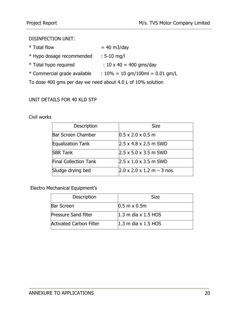
DISINFECTION UNIT:
* Total flow = 40 m3/day
* Hypo dosage recommended : 5-10 mg/l
* Total hypo required : 10 x 40 = 400 gms/day
* Commercial grade available : 10% = 10 gm/100ml = 0.01 gm/L
To dose 400 gms per day we need about 4.0 L of 10% solution
UNIT DETAILS FOR 40 KLD STP
Civil works
Description Size
Bar Screen Chamber 0.5 x 2.0 x 0.5 m
Equalization Tank 2.5 x 4.8 x 2.5 m SWD
SBR Tank 2.5 x 5.0 x 3.5 m SWD
Final Collection Tank 2.5 x 1.0 x 3.5 m SWD
Sludge drying bed 2.0 x 2.0 x 1.2 m – 3 nos.
Electro Mechanical Equipment’s
Description Size
Bar Screen 0.5 m x 0.5m
Pressure Sand filter 1.3 m dia x 1.5 HOS
Activated Carbon Filter 1.3 m dia x 1.5 HOS
Project Report M/s. TVS Motor Company Limited
ANNEXURE TO APPLICATIONS 21
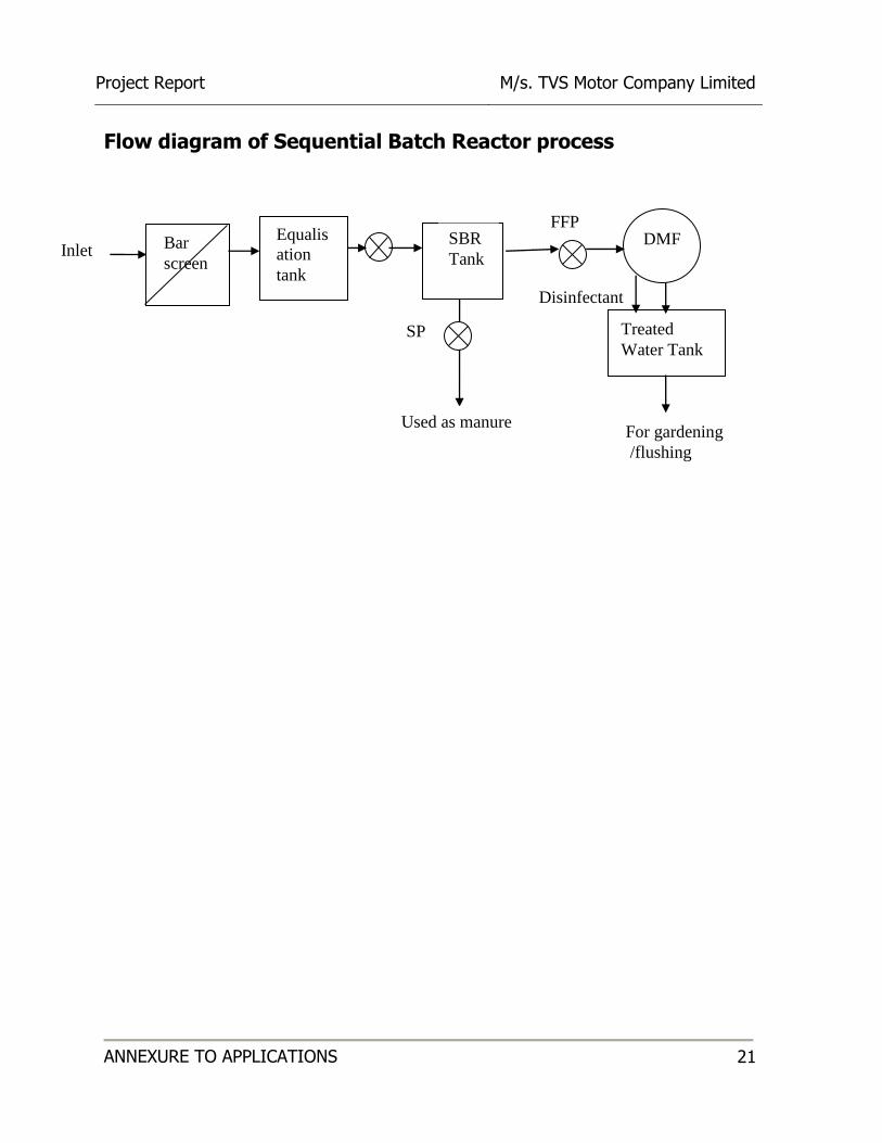
Flow diagram of Sequential Batch Reactor process
RSP
For gardening
/flushing
Disinfectant
Inlet
Treated
Water Tank
FFP SBR
Tank
Equalis
ation
tank
DMF Bar
screen
Used as manure
SP

Project Report M/s. TVS Motor Company Limited
ANNEXURE TO APPLICATIONS 22
ANNEXURE: D
WATER BALANCE CHART
(After construction of proposed buildings)
Wastewater generated 33 KLD
Daily water Requirement
24 KLD
Total Raw Water demand (Start Up)
36 KLD
Toilet Flushing 12 KLD
Sewage Treatment Plant 40 KLD(Capacity)
Gardening 21 KLD
Recycle for Flushing
Toilet 12KLD
Project Report M/s. TVS Motor Company Limited
ANNEXURE TO APPLICATIONS 23
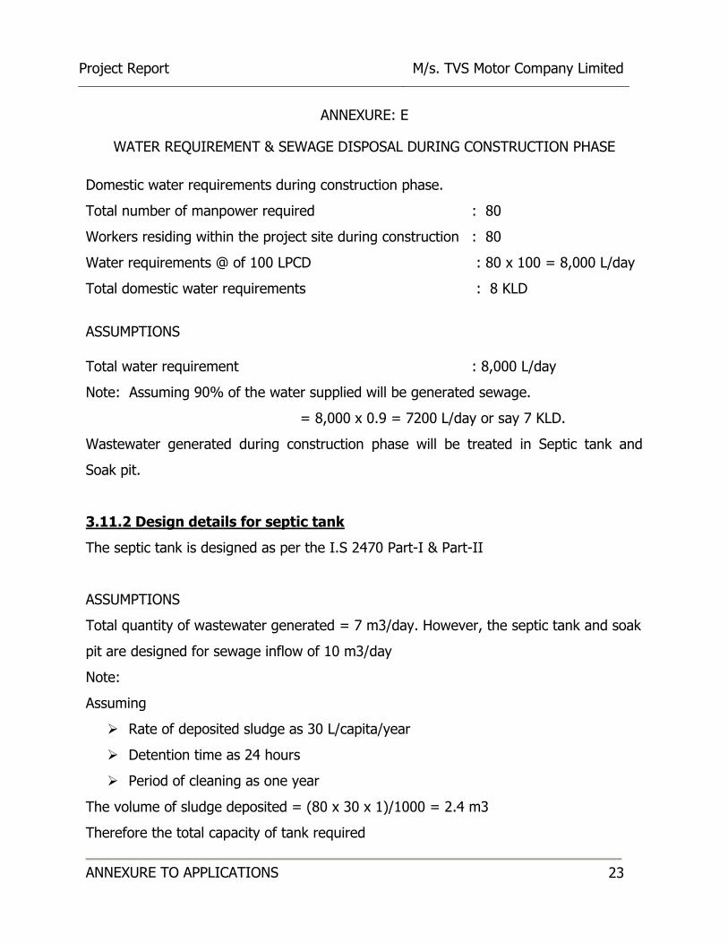
ANNEXURE: E
WATER REQUIREMENT & SEWAGE DISPOSAL DURING CONSTRUCTION PHASE
Domestic water requirements during construction phase.
Total number of manpower required : 80
Workers residing within the project site during construction : 80
Water requirements @ of 100 LPCD : 80 x 100 = 8,000 L/day
Total domestic water requirements : 8 KLD
ASSUMPTIONS
Total water requirement : 8,000 L/day
Note: Assuming 90% of the water supplied will be generated sewage.
= 8,000 x 0.9 = 7200 L/day or say 7 KLD.
Wastewater generated during construction phase will be treated in Septic tank and
Soak pit.
3.11.2 Design details for septic tank
The septic tank is designed as per the I.S 2470 Part-I & Part-II
ASSUMPTIONS
Total quantity of wastewater generated = 7 m3/day. However, the septic tank and soak
pit are designed for sewage inflow of 10 m3/day
Note:
Assuming
Rate of deposited sludge as 30 L/capita/year
Detention time as 24 hours
Period of cleaning as one year
The volume of sludge deposited = (80 x 30 x 1)/1000 = 2.4 m3
Therefore the total capacity of tank required

Project Report M/s. TVS Motor Company Limited
ANNEXURE TO APPLICATIONS 24
= Volume of sewage + Volume of sludge
= 10 + 2.4 = 12.4 m3
Now assuming 1.5 m SWD, we have
The floor area of the tank = 12.4/1.5 = 8.26 m2
Let us assume length is thrice the width
3 B2 = 8.26 m2
B = 1.65 m
L = 3 x 1.65
= 4.95 m
However from the practical point of view keep minimum, proposed to provide a septic
tank of size 4.95 m x 1.65 m x 1.8 m (1.5 + 0.3 free board) depth with inlet and outlet
chambers, baffles, sludge withdrawal pipe with valve and covered with RCC slab with
air vent etc. complete.
Design details for soak pit
The soak pit is designed as per IS 2470 Part – I and Part – II
The soak pit is designed by assuming the percolating capacity of the soaking media as
1,250 L/m3/day.
Therefore, Volume of soaking media required for soak pit= 10000/1,250 = 8 m3
Let the depth of the soak pit be 1.5 m.
Therefore, area of soak pit = 8/1.5 = 5.3 m2
Therefore, diameter = 2.59 m
Therefore provide soak pits of 2.59 m dia and 1.5 m depth

Project Report M/s. TVS Motor Company Limited
ANNEXURE TO APPLICATIONS 25
ANNEXURE: F
SOLID WASTE GENERATION & ITS MANAGEMENT - CONSTRUCTION PHASE:
The total manpower : 80
Considering solid waste generation @ 0.2 kg/capita/day
Total solid waste generation : 80 x 0.2 = 16 Kg/day
The solid Wastes generated will be collected, segregated, composted in compost pits
and the product will be used as manure for landscape development.
OCCUPANCY PHASE:
The wastes that are generated from the day to day activities which are in solid form are
categorized as solid wastes. Solid Wastes include dry refuse and street sweepings,
crockery, Kitchen Wastes, and also electronic wastes. The quantity of solid waste
generated from the project is calculated as follows.
Sl. No. Solid Waste Generation Details
A Existing Building:
1 Total no. of occupants in the building: 300 persons Assuming solid waste generation rate as 0.2 kg/person/day Quantity of Solid Waste Generated = 300 X 0.2 = 60 Kg/day ----- A
B Proposed Building:
1. Total no. of occupants in the building: 500 persons Assuming solid waste generation rate as 0.2 kg/person/day Quantity of Solid Waste Generated = 500 X 0.2 = 100 Kg/day ----- B
C Total Quantity of Solid Waste generated from project (After expansion) = A + B = 60 + 100 = 160 Kg/day
a) Organic solid waste: 60% of the total waste:96 Kg/day b) Inorganic solid waste: 40% of the total waste:64 Kg/day
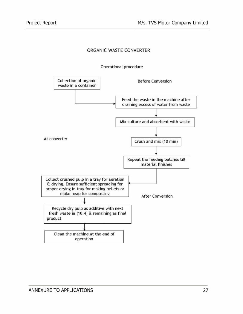
D Presently solid waste from the existing building of the institute composted through vermicomposting. Further, Organic Converter is proposed to treat the solid waste from the project and the product will be used as manure for Landscape development. The inorganic waste from the project is sent for recycling.
Project Report M/s. TVS Motor Company Limited
ANNEXURE TO APPLICATIONS 26
The solid Wastes generated will be segregated at its point of generation and collected
separately in different color coded Synthetic Bins depending upon the basis of its Bio
Degradability at a common designated point. Organic solid waste from the project will
be treated in an organic waste converter and is used as manure for Landscape. The
inorganic solid waste is sent for recycling.
Project Report M/s. TVS Motor Company Limited
ANNEXURE TO APPLICATIONS 27

Project Report M/s. TVS Motor Company Limited
ANNEXURE TO APPLICATIONS 28
The compost formed by this method will have a pH value of 6.5 – 7.5 C: N ratio of 15:1
and organic matter of 40 – 50%.

Project Report M/s. TVS Motor Company Limited
ANNEXURE TO APPLICATIONS 29
SECONDARY SLUDGE FROM STPs:
The solid waste generated from the STP’s is in the form of stabilized sludge. Then is
passed through the sludge drying beds, the solids obtained as semi solid cakes are used
as organic manure for the development of plantations within the premises. The quantity
of sludge so produced will be:
Rate: 40 m3/day and Sludge : 15 Kg/Day
HAZARDOUS WASTE:
The Hazardous waste generated from the project is waste oil of about 50 –100
litres/annum which will be stored in closed barrels and disposed to KSPCB approved and
CPCB register waste oil re-processors. Authorization will be obtained from KSPCB as per
Hazardous waste (Management & Handling) Amendment Rules, 2008.
Project Report M/s. TVS Motor Company Limited
ANNEXURE TO APPLICATIONS 30
ANNEXURE – G
ENVIRONMENTAL MANAGEMENT PLAN:
1. INTRODUCTION:
The Environmental Management Plan (EMP) is aimed at mitigating the possible adverse
impact of a project and ensuring the existing environmental quality. The EMP converse
all aspects of planning, construction and operation of the project relevant to
environment. It is essential to implement the EMP right from the planning stage
continuing throughout the construction and operation stage. Therefore the main
purpose of the Environmental Management Plan (EMP) is to identify the project specific
activities that would have to be considered for the significant adverse impacts and the
mitigation measures required.
The construction phase impacts are mostly short term, restricted to the plot area
and not envisaged on the larger scale. In the operational phase the environmental
impacts are due to continuous operation of the project, hence, the emphasis in the
Environment Management Plan (EMP) is to minimize such impacts. The following
mitigation measures are recommended in order to synchronize the economic
development of the project area with the environmental protection of the region.
The emphasis on the EMP development is on the following;
Mitigation measures for each of the activities causing the environmental Impact.
Monitoring plans for checking activities and environmental parameters and
monitoring responsibilities.
Role responsibilities and resource allocation for monitoring; and
Implementation of the Scheduled plan.
Environmental management plan has been discussed in the following sections
separately for Construction phase and Operational phase.
Project Report M/s. TVS Motor Company Limited
ANNEXURE TO APPLICATIONS 31
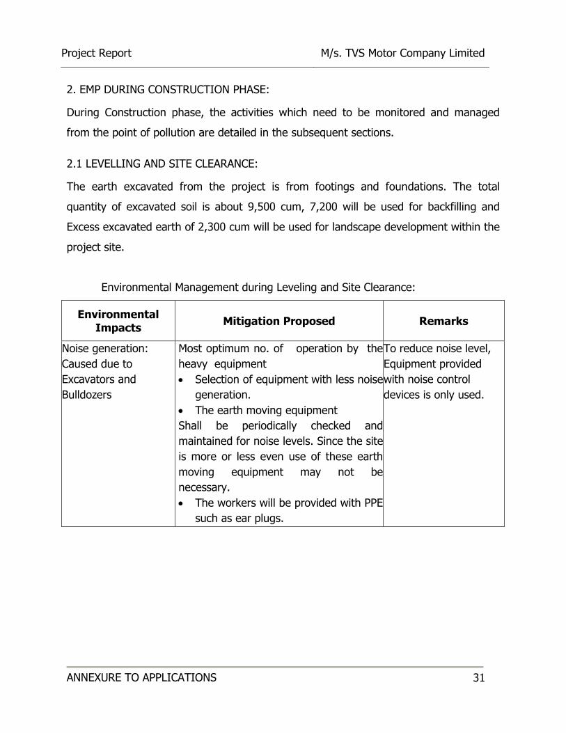
2. EMP DURING CONSTRUCTION PHASE:
During Construction phase, the activities which need to be monitored and managed
from the point of pollution are detailed in the subsequent sections.
2.1 LEVELLING AND SITE CLEARANCE:
The earth excavated from the project is from footings and foundations. The total
quantity of excavated soil is about 9,500 cum, 7,200 will be used for backfilling and
Excess excavated earth of 2,300 cum will be used for landscape development within the
project site.
Environmental Management during Leveling and Site Clearance:
Environmental Impacts
Mitigation Proposed
Remarks
Noise generation:
Caused due to
Excavators and
Bulldozers
Most optimum no. of operation by the
heavy equipment
Selection of equipment with less noise
generation.
The earth moving equipment
Shall be periodically checked and
maintained for noise levels. Since the site
is more or less even use of these earth
moving equipment may not be
necessary.
The workers will be provided with PPE
such as ear plugs.
To reduce noise level,
Equipment provided
with noise control
devices is only used.

Project Report M/s. TVS Motor Company Limited
ANNEXURE TO APPLICATIONS 32
Dust generation:
Leveling operations
results in the emission
of dust.
The site cleared will be periodically
watered to reduce dust emissions.
Barricades like metal sheets will be
provided all round the premises to
avoid fugitive dust emission in to the
neighboring area apart from water
sprinkling.
The workers will be provided with PPE
such as nose masks and goggles to
reduce impact.
Tertiary treated
water to be used.
2.2 TRANSPORTATION OF CONSTRUCTION MATERIALS:
During the Transportation of construction materials, minimum no. of vehicles will be
used. Most optimum route is planned to reduce the impact of transportation activity
on the environment.
Environmental Management during Transportation
Environmental Impacts Mitigation Proposed
Noise generation
Quality fuel will be used.
Periodic maintenance of vehicles is required.
Dust generation
Quality packaging of the construction materials
Construction materials will be covered with tarpaulin
sheet to prevent them from being air borne
The vehicle speed shall be regulated
The workers transporting materials will be provided with
PPE such as nose masks to reduce impact of air borne
dust on their health.
Vehicular emissions Periodic emission check for vehicles is required
Clean fuel shall be used for vehicles

Project Report M/s. TVS Motor Company Limited
ANNEXURE TO APPLICATIONS 33
2.3 CONSTRUCTION ACTIVITIES:
During the construction work, the following impacts are identified to monitor and
mitigate the level of impact.
Environmental Management during Construction
Environmental
Impacts Mitigation Proposed Remarks
Noise generation
Less noise generating equipment
Personnel Protective Equipment (PPE)
such as ear plugs and helmets will be
provided for workers
The working hours to be imposed on the
construction workers.
Implementation
responsibility:
Contractor - Civil
Works
Dust generation PPE in the form of nose masks will be
provided for construction workers.
Use of water sprays to prevent dust from
being air borne
Barricades like metal sheets will be
provided all around the premises to avoid
fugitive dust emission into the neighboring
area apart from water sprinkling.
Implementation
responsibility:
Contractor
Water discharge
(construction works)
Sewage generated will be treated in Septic
tank and Soak Pit.
Implementation
responsibility:
Contractor
Air Emissions from
Construction
machinery
Periodic check and regular maintenance
of construction machinery for emissions.
Clean fuel are used in equipments
Implementation
responsibility:
Contractor

Project Report M/s. TVS Motor Company Limited
ANNEXURE TO APPLICATIONS 34
2.4 WASTEWATER DISCHARGE:
The sewage generated from the labors during construction is estimated to be about
7 KLD. The sewage will be treated in Septic tank and soak pit.
2.4.1 LABOUR CAMPS:
Environmental Management for Labor Camp:
Environmental
Impacts Mitigation Proposed Remarks
Wastewater
generation
Provision of adequate sanitation facilities.
Labour camps are not provided toilet blocks
were provided for construction works.
Responsibility:
Contractor
Usage of water Water for construction workers will be
supplied in required quantities.
Responsibility:
Contractor
Solid waste
generation
Segregation of Dry Waste and Wet Waste.
Adequate facilities to handle solid Wastes generated will be collected, segregated, composted in compost pits and the product will be used as manure for landscape development.
Implementation
responsibility:
Contractor –
maintenance.
2.5 DISPOSAL OF EXCAVATED EARTH:
The earth excavated from the project is from footings and foundations. The total
quantity of excavated soil is about 9,500 cum, 7,200 will be used for backfilling and
Excess excavated earth of 2,300 cum will be used for landscape development within the
project site.
2.6 PERSONNEL SAFETY SYSTEM:
It is planned to adopt the safe working practices which shall govern all construction
works undertaken throughout the project. Following Safety Aids to all laborers will be
provided:

Project Report M/s. TVS Motor Company Limited
ANNEXURE TO APPLICATIONS 35
Safety Helmets, Safety Belts, Safety Shoes, Hand gloves
Gumboots while concreting
Safety Goggles while welding/ Stone dressing etc.
Facemasks and full body kit while Pest control
Implementation of Safety procedures such as:
• Using proper lifting techniques
• Using Safe Scaffolds
• Hot work permits for Fabrication and Welding
FINANCIAL ALLOCATION AND BUDGETARY PROVISION FOR EMP ASPECTS
(CONSTRUCTION ASPECTS)
Sl. No.
Description
Financial Provision in Lakhs
Capital Cost
Recurring Cost
1 Environmental Management Plan during construction phase:
• Sprinkling to control fugitive dusts
Construction & curing purposes Flushing
2.0 2.0 1.0
0.5 0.5 0.5
2 Soak Pit and septic tank 3.0 -
3 Sewage Treatment Plants for Operation Phase 25.0 -
4 Installation of Organic Converter for Operation Phase 12.0 -
5 Potable water requirement for the construction workers 5.0 0.5
6 Maintenance of Vehicles and equipment’s - 1.0
7 Temporary Storm Water Drains 3.0 2.0
8 Personal protection safety gadgets and health care. 1.0 0.5
9 First aid facilities for workers 1.0 0.5
11 Plantation of Saplings 5.0 1.0
12 Environmental Monitoring Plan (Air, Noise, Water and Solid Waste).
- 1.0
13 TOTAL 60 8
Contingency at 10 % 6.0 0.8
TOTAL 66 8.8
Project Report M/s. TVS Motor Company Limited
ANNEXURE TO APPLICATIONS 36
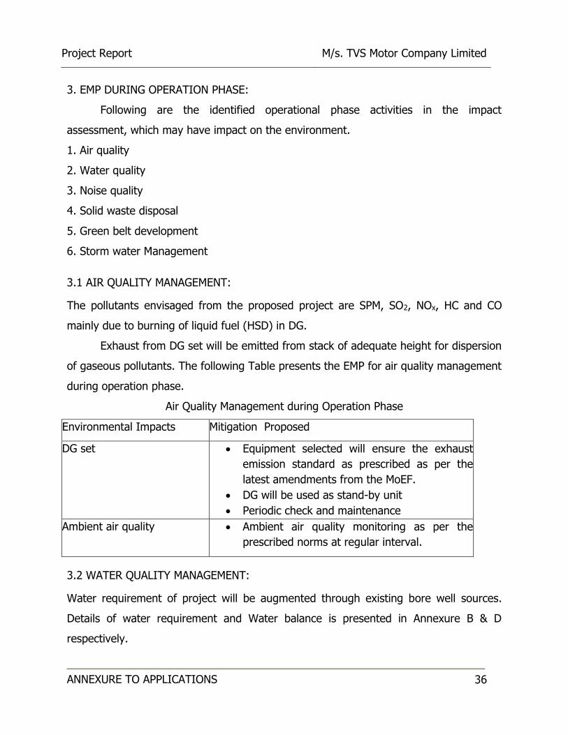
3. EMP DURING OPERATION PHASE:
Following are the identified operational phase activities in the impact
assessment, which may have impact on the environment.
1. Air quality
2. Water quality
3. Noise quality
4. Solid waste disposal
5. Green belt development
6. Storm water Management
3.1 AIR QUALITY MANAGEMENT:
The pollutants envisaged from the proposed project are SPM, SO2, NOx, HC and CO
mainly due to burning of liquid fuel (HSD) in DG.
Exhaust from DG set will be emitted from stack of adequate height for dispersion
of gaseous pollutants. The following Table presents the EMP for air quality management
during operation phase.
Air Quality Management during Operation Phase
Environmental Impacts Mitigation Proposed
DG set Equipment selected will ensure the exhaust
emission standard as prescribed as per the
latest amendments from the MoEF.
DG will be used as stand-by unit
Periodic check and maintenance
Ambient air quality Ambient air quality monitoring as per the
prescribed norms at regular interval.
3.2 WATER QUALITY MANAGEMENT:
Water requirement of project will be augmented through existing bore well sources.
Details of water requirement and Water balance is presented in Annexure B & D
respectively.

Project Report M/s. TVS Motor Company Limited
ANNEXURE TO APPLICATIONS 37
The sewage generated from the proposed project will be treated in the proposed
STP. The treatment scheme for domestic sewage generated from project is discussed
in Annexure - C. Treated water will be reused for flushing, gardening etc., and the
following Table presents the EMP for water quality.
Water Quality Management during Operation Phase
Environmental impacts Mitigation Proposed
Wastewater Treated with proposed sewage treatment
plant to produce tertiary treated water which is reused for
secondary purposes such as flushing, landscaping
development, irrigation etc.,
Water conservation measures will be encouraged
3.3 NOISE MANAGEMENT:
High noise generating units such as DG sets will be provided with acoustic
enclosures. Green belt on the project boundary will further act as noise barrier and
helps in attenuation of noise. The Table presents the EMP for noise level.
Noise Management during Operation Phase
Environmental Impacts Mitigation Proposed
Noise from DG set area
Acoustic enclosures are provided for DG set
DG set are installed in an area (utility section) where
the access will be restricted
The use of PPE (ear plugs) will be mandatory in this
area
Selection of equipment to ensure that the residual
noise level of < 55 dB(A)
Noise levels will be checked periodically using a noise
pressure level meter

Project Report M/s. TVS Motor Company Limited
ANNEXURE TO APPLICATIONS 38
3.4 SOLID WASTE MANAGEMENT:
The solid wastes generated during operation phase can be categorized under
Three types: Domestic/Residential Waste
Wet Garbage: Food waste, Lawn mowing wastes etc.
Dry Garbage: Paper, Plastic, Bottles, etc.
Sludge from Sewage Treatment Plant (STP)
The solid waste generated and its management is detailed in Annexure – F.
The various mitigation measures to be adopted during collection and disposal of wastes
are as follows:
It is preferable that the container and bins used for collection of waste should be
of closed type and waste is not exposed thus possibility of spreading of disease
through flies and mosquitoes is minimized.
Collection system should be properly supervised so that quick and regular
removal of waste from the dustbin is practiced.
Door to door collection shall be done in each building to collect the solid wastes.
3.5 STORM WATER MANAGEMENT:
As the project location is blessed with fairly good rainfall, it is planned to collect
the storm water at different gradients of the location. There will be rainfall runoff from
building roof-tops, roads and pavements and greenbelt area. Necessary provision will
be made to collect the quantity of rainfall runoff during the most rainy day of season.
Necessary rain harvesting pit/recharge pit at every 30 m centre to centre have been
envisaged. A storm water drain with 600mm wide with RCC precast perforated cover
and 1800 mm dia RCC precast Ring soak pit will be provided around the periphery of
property and designed as per building by-law (schedule 12). The details of the rain
water harvesting facilities can be interpreted in the layout plan.
Project Report M/s. TVS Motor Company Limited
ANNEXURE TO APPLICATIONS 39
3.6 LANDSCAPE DEVELOPMENT:
The landscape of project site has been planned to provide a clean, healthy and
beautiful green environment for the people. Within the proposed project site 35.56 % is
open space, and in this about 32.52 % of the total space has been designated for
landscape development and has been designed to achieve a blend between modern
building and various species of plants, shrubs, to create a clean, healthy and aesthetic
environment that provides a visual retreat and relaxation to the occupants of these
buildings.
In this project about 1283 trees are existing in the project and about 960 trees will be
proposed in the training centre.
Following approach will be adopted for Vegetation and Ground Management. It is
planned to include an ecologically knowledgeable landscape architect as an integral
member of the design team.
Preservation of existing vegetation, especially native plants, will possibly be
incorporated. Avoid fencing off property where possible to make landscape available to
community increasing project integration.
Decrease paving and monoculture lawns.
Avoid replacing mature trees with young seedlings.
Protect existing plants during construction. Delineate the "drip line" around trees
and demark or fence off areas to avoid damage.
Contain heavy equipment and stockpiling areas to predefined areas.
Design new plantings as diverse communities of species well adapted to the site.
Plant native species of varying ages. Select vegetation that attracts wildlife.
Avoid invasive species and monocultures (same species, same age).

Project Report M/s. TVS Motor Company Limited
ANNEXURE TO APPLICATIONS 40
HEALTH RISK AND DISASTER MANAGEMENT:
Public health and safety:
Since all the construction related activities are confined to the project site, minimal
health related impacts are envisaged within the project influenced area during the
construction stage.
At the project site on an average of 80 no. of persons will be engaged, who face direct
exposure to dust and noise generated from the construction activity. This is likely to
cause health related affects such as asthma, bronchitis etc. and hearing impairments
respectively.
To minimize these anticipated impacts, suitable actions like
• Use of water sprinklers to prevent dust from being air borne.
• Providing suitable Personal Protective Equipment (PPE) like mouth mask with
filters, noise mask, helmets etc.
• Periodic health checkup camp for the labourers will be arranged.
• Provision of safety belts.
• In case of injury on site medical treatment and transport will be organized.
Due to operation of the proposed project, there will be enhancement in public Health
and safety.
Regular visit of resident medical officer to take care of the first aid and primary
medication in case of emergency for apartment occupants and laborers.
First Aid kit with primary medicines will always be available in the medical center.
Display of action plan and preparedness measures during emergency situations.

Project Report M/s. TVS Motor Company Limited
ANNEXURE TO APPLICATIONS 41
5. EMP IMPLEMENTATION SCHEDULE:
Phased according to the priority, the implementation schedule is presented in the
following table.
Implementation Schedule for EMP
Sl.
No. Recommendations Requirement
1 Air pollution control measures Before commissioning of respective Units
2 Water pollution control measures Before commissioning of the project
3 Noise control measures Along with the commissioning of the
Project
4 Solid waste management During commissioning of the project
5 Green belt development Stage-wise implementation
The responsibility of EMP implementation lies with the project promoter for a period of
3 years. Once the facility is established, the EMP responsibility will be properly handed
over with clearly defined procedures and guidelines.

Project Report M/s. TVS Motor Company Limited
ANNEXURE TO APPLICATIONS 42
FINANCIAL ALLOCATION AND BUDGETARY PROVISION FOR EMP ASPECTS
(OCCUPANCY PHASE)
Sl.
No. Description
Financial Provision in
Lakhs
Capital
Cost
Recurring
Cost
1 Operation of Sewage Treatment Plant - 4.0
2 Reclaimed Sewage Distribution Network 6.0 1.0
3 Rain water harvesting tanks and its facilities 5.0 0.5
4 Ground water recharging pits & its management 5.0 0.5
5 Landscaping 3.0 1.0
6 Solid waste management per annum 2.0 1.0
7 Environmental Monitoring Plan per annum
(Air, Noise, Water)
- 1.0
8 TOTAL 19 9.5
Contingency at 10 % 1.9 0.95
TOTAL 20.9 10.45

Project Report M/s. TVS Motor Company Limited
ANNEXURE TO APPLICATIONS 43
6. ENVIRONMENTAL MONITORING ROUTINES:
A comprehensive monitoring program is suggested below:
Monitoring Schedule for Environmental Parameters
Sl. No
Particulars
Monitoring frequency
Duration of monitoring
Important parameters for
monitoring
I Air Quality
1. Ambient Air monitoring
Project premises
Once in a month
24 hourly sample
RSPM, SPM, SO2,
and NOx
2.
Stack monitoring
Once in a year if required
Grab
SPM, SO2, NOx, HC and CO
II Water and Wastewater Quality
1. Water Quality
i. Groundwater at two locations (up-gradient and down-gradient) of treated effluent discharge area/land
Once in a month
Grab As per KSPCB requirements
2. Wastewater quality
i. Inlet into STP NA NA -
ii. Treated effluent prior to discharge NA NA -
III Soil Quality
1. Within project premises at 1 location on effluent discharging area/land
Once in 6 month
Composite sample
As per KSPCB requirements
2. Ecological preservation and up gradation
Seasonal Visual observations
Survival rate
IV Noise monitoring
1. Project premises Once in 6 month
Day and night As per KSPCB requirements

Project Report M/s. TVS Motor Company Limited
ANNEXURE TO APPLICATIONS 44
ANNEXURE: H
RAIN WATER MANAGEMENT PLAN:
VOLUME OF RAIN WATER HARVESTED.
The total amount/quantity of water i.e., received in the form of rainfall over an area is
called the rain water endowment of that area, out of which the amount of water that
can be effectively harvested is called the rain water harvesting potential.
Rain Water harvesting potential = Intensity of Rainfall (m) x Roof Area
x Impermeability Factor.
The collection efficiency accounts for the fact that all the rain water falling over an area
cannot be effectively harvested due to losses on account of evaporation, spillage or run
off etc.
According to the data available from the Indian Meteorological Department, the
Average annual rainfall around month of September = 194.80mm
Assuming that about 90 % Rainfall can be effectively harvested.
Number of Rainy Days = 9.3
Therefore the I.R = 194.80/9.3= 20.94 mm/day or 0.02094 m/Day
Or 0.021 m/day
The Ground coverage area of the institute for quality and leadership
= 52,721 sq m
For rain water harvesting consider 75 % of this total area = 39,541 sq m.
Total Quantity of Rain Water that can be harvested from the proposed project is
calculated as below.
Rain water (Q) from Roof top = 0.021 x 39,541 x 0.9
= 747.32 cum/day or say 748 cum/day.
However, the Proponent has proposed to initially utilize the entire quantity of the rain
water by providing Roof water sump capacity of 800 cum.

Project Report M/s. TVS Motor Company Limited
ANNEXURE TO APPLICATIONS 45
7.3 STORM WATER MANAGEMENT:
Storm water disposal is divided into 2 Groups:
Terrace Storm water disposal: The entire rainwater from the terrace would be disposed
through suitable rain water pipes and collecting in the dedicated rain water collection
sump, which is proposed at site level. This water will be utilized for domestic purpose
(as detailed in VOLUME OF RAIN WATER HARVESTED).
Site (Paved and landscape area) Storm water disposal: The entire storm water from the
site would be disposed off through suitable RCC Box drainage system to the rainwater
recharge pits and the excess is diverted to external storm water drainage.
The amount of storm water that the landscaped area will produce can be determined by
considering the impermeability factor to be 0.3
Q = 0.021 x 97,358 sq m x 0.3
= 613.35 cum/day or say 614 cum/day
The amount of storm water that the paved area will produce can be determined by
considering the impermeability factor to be 0.9
Q = 0.021 x 28,415 sq m x 0.9
= 537.04 cum/day or say 538 cum/day
The Total amount of storm water = landscaped area + paved area
= 614 + 538 cum / day
= 1152 cum/day
The proponents shall also provide Recharging Pits along with the inner periphery of the
boundary wall with recharging pit of size 1.2 m dia x 2.5 m deep spaced at 20 m center
to center. These recharging pits are filled with graded media comprising of Boulder at
bottom and with coarse aggregates to facilitate percolation of harvested rain water to
Recharge Ground Water table. The Recharge Pits are interconnected in such a way that
the rain led to the first recharge pit is also led to the next pit. The excess rain water
shall be drained off to the storm water drain.
Project Report M/s. TVS Motor Company Limited
ANNEXURE TO APPLICATIONS 46
ANNEXURE: I
DISASTER MANAGEMENT PLANS FOR PRE CONSTRUCTION PHASE:
Risk and disaster management plan:
Disaster is an unexpected event due to sudden failure of the system, external
threats, internal disturbances, earth quakes, fire and accidents. Thus an appropriate
management plan shall be incorporated.
Precautions:
Once the likelihood of the disaster is suspected, preventive actions should be
undertaken by the project in-charge.
Conditional maintenance of equipment, materials, and expertise for use during
emergency.
The electrical systems shall be provided with automatic circuit breakers activated
by over current.
Proper escape routes are planned and displayed in the public domain.
Selected representatives are given proper training to guide other inhabitants
during Fire accidents.
Periodic awareness program is conducted for the workers on their roles during
emergency situations.
Important telephone numbers like police authorities, fire department and
hospitals etc., of use during emergency situations will be made available.
Project Report M/s. TVS Motor Company Limited
ANNEXURE TO APPLICATIONS 47
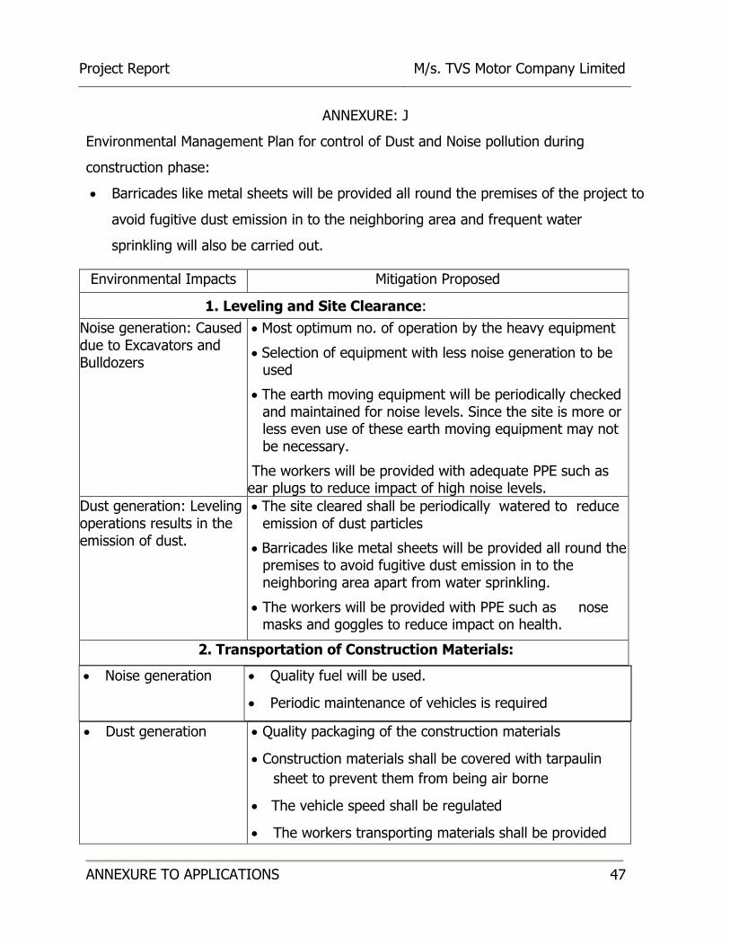
ANNEXURE: J
Environmental Management Plan for control of Dust and Noise pollution during
construction phase:
Barricades like metal sheets will be provided all round the premises of the project to
avoid fugitive dust emission in to the neighboring area and frequent water
sprinkling will also be carried out.
Environmental Impacts Mitigation Proposed
1. Leveling and Site Clearance:
Noise generation: Caused due to Excavators and Bulldozers
Most optimum no. of operation by the heavy equipment
Selection of equipment with less noise generation to be used
The earth moving equipment will be periodically checked and maintained for noise levels. Since the site is more or less even use of these earth moving equipment may not be necessary.
The workers will be provided with adequate PPE such as ear plugs to reduce impact of high noise levels.
Dust generation: Leveling operations results in the emission of dust.
The site cleared shall be periodically watered to reduce emission of dust particles
Barricades like metal sheets will be provided all round the premises to avoid fugitive dust emission in to the neighboring area apart from water sprinkling.
The workers will be provided with PPE such as nose masks and goggles to reduce impact on health.
2. Transportation of Construction Materials:
Dust generation
Quality packaging of the construction materials
Construction materials shall be covered with tarpaulin
sheet to prevent them from being air borne
The vehicle speed shall be regulated
The workers transporting materials shall be provided
Noise generation Quality fuel will be used.
Periodic maintenance of vehicles is required
Project Report M/s. TVS Motor Company Limited
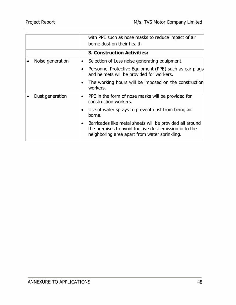
ANNEXURE TO APPLICATIONS 48
with PPE such as nose masks to reduce impact of air
borne dust on their health
3. Construction Activities:
Noise generation
Selection of Less noise generating equipment.
Personnel Protective Equipment (PPE) such as ear plugs and helmets will be provided for workers.
The working hours will be imposed on the construction workers.
Dust generation PPE in the form of nose masks will be provided for construction workers.
Use of water sprays to prevent dust from being air borne.
Barricades like metal sheets will be provided all around the premises to avoid fugitive dust emission in to the neighboring area apart from water sprinkling.
Project Report M/s. TVS Motor Company Limited
ANNEXURE TO APPLICATIONS 49
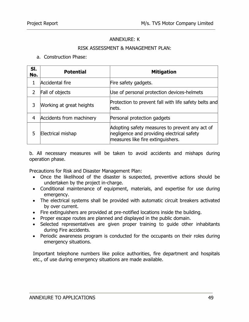
ANNEXURE: K
RISK ASSESSMENT & MANAGEMENT PLAN:
a. Construction Phase:
Sl. No.
Potential Mitigation
1 Accidental fire Fire safety gadgets.
2 Fall of objects Use of personal protection devices-helmets
3 Working at great heights Protection to prevent fall with life safety belts and nets.
4 Accidents from machinery Personal protection gadgets
5 Electrical mishap Adopting safety measures to prevent any act of negligence and providing electrical safety measures like fire extinguishers.
b. All necessary measures will be taken to avoid accidents and mishaps during operation phase. Precautions for Risk and Disaster Management Plan:
Once the likelihood of the disaster is suspected, preventive actions should be undertaken by the project in-charge.
Conditional maintenance of equipment, materials, and expertise for use during emergency.
The electrical systems shall be provided with automatic circuit breakers activated by over current.
Fire extinguishers are provided at pre-notified locations inside the building. Proper escape routes are planned and displayed in the public domain. Selected representatives are given proper training to guide other inhabitants
during Fire accidents.
Periodic awareness program is conducted for the occupants on their roles during emergency situations.
Important telephone numbers like police authorities, fire department and hospitals etc., of use during emergency situations are made available.
Project Report M/s. TVS Motor Company Limited
ANNEXURE TO APPLICATIONS 50
ANNEXURE: L
SOIL INVESTIGATION REPORT
Project Report M/s. TVS Motor Company Limited
ANNEXURE TO APPLICATIONS 51
ANNEXURE: M
TRAFFIC MANAGEMENT MEASURES
• Merging of vehicles will be performed only to left traffic from the exit gates, this
ensures safety.
• To establish smooth entry & exit of vehicles, bell mouth shape geometry is
provided at the gates. This ensures smooth transition for merging of vehicles.
• Yellow paint junction boxes are painted at the locations to create psychological
barrier for through drivers to control the speed.
• Rubber humps are introduced for the outgoing vehicles at the exit gate drive
way. All gates are manned with efficient security who can guide the entry and
exit of vehicles.
• Adequate sign & guide posts for traffic as per IRC (Indian Roads Congress).
• Road marking, STOP lines, parking lanes, slot numbers etc, must be clearly
painted so as to guide the vehicles.
Project Report M/s. TVS Motor Company Limited
ANNEXURE TO APPLICATIONS 52
ANNEXURE: N
ENERGY CONSERVATION ASPECTS PROPOSED IN THE PROJECT:
a. Energy Efficient motors, whose efficiency is not lower than the limits specified in section 8.2.2 of the ECBC code will be installed. b. Dry type Transformer with efficiency not lower than the limits specified in section 8.2.1 of the code shall be considered. c. Power monitoring, recording and check metering will be provided in the main LT panels on the incoming feeders and individual outgoing feeders covering all parameters such as Current, Voltage, Energy & THDI as stipulated in section 8.2.4 of the code. d. Cable sizing and design of distribution system will ensure that the total distribution loss will not exceed 1% of the total energy consumed as stipulated in section 8.2.5.1 of the code. e. Timer controls will be incorporated in the distribution board of external lighting to save energy as stipulated in section 7.4 of the code. f. Power conditioning equipment will be installed to limit THDI to 5% which shall also improve power factor to 0.95 as stipulated in section 8.2.3 of the code. g. Solar Lighting shall be provided at strategic locations in outdoor areas. h. Water cooled Chillers are used instead of air cooled chillers which provide energy savings. j. VFD drives shall be provided for secondary pumps for water cooled chillers and lifts which will result in energy savings.

Project Report M/s. TVS Motor Company Limited
ANNEXURE TO APPLICATIONS 53
ANNEXURE – 0
PROJECT RELATED DRAWINGS & PLANS