
Appendix to PR-23 Instruction Manual for K-Patents ... sucrose), and the subsequent collection of...
56
Document/Revision No. IM-GB-PR23-AC-VACCINES: Rev. 1.01 Effective: November 1, 2013 K-Patents Pharma Refractometer PR-23-AC Appendix to PR-23 Instruction Manual for K-Patents Products Intended for Use in Vaccine Production
Transcript of Appendix to PR-23 Instruction Manual for K-Patents ... sucrose), and the subsequent collection of...

Document/Revision No. IM-GB-PR23-AC-VACCINES: Rev. 1.01Effective: November 1, 2013
K-Patents Pharma Refractometer PR-23-AC
Appendix to PR-23 Instruction Manual for K-Patents Products Intended for Use in Vaccine Production

Document/Revision No. IM-GB-PR23-VACCINES: Rev. 1.01 Effective: November 1, 20132
Appendix to the Instructions Manual PR-23
Do not underestimate or neglect the laboratory and factory safety rules:
● Before you start, assess the workplace to determine if hazards are present, or are likely to be present, which necessitate the use of personal protective equipment, e.g.:
● protective clothing and shoes ● safety goggles ● protective gloves ● respiratory shields and devices
● Locate the nearest safety equipment, extinguishers, eyewash, and emergency shower

© Copyright K-Patents 2013. All rights reserved. 3
ContentsSection 1 K-Patents Products for Vaccine Production and
Sucrose Gradient Ultracentrifugation ............................................................................... 51.1 DesignQualification ....................................................................................................... 6
Section 2 The Pharma Refractometer PR-23-AC ................................................................................ 72.1 System description ........................................................................................................ 72.2 System components ...................................................................................................... 8
2.2.1 Checklist of components .................................................................................... 82.3 Pharma Refractometer Sensor PR-23-AC-62-HSS-SC ............................................. 10
2.3.1 Sensor Model code .......................................................................................... 102.3.2 PharmaMiniflowCellModelcode ................................................................... 10
2.4 Indicating Transmitter DTR-GP-SC ............................................................................. 122.4.1 Indicating Transmitter Model code................................................................... 12
2.5 Pharma Vaccines Accessories .................................................................................... 132.5.1 ComputerCommunicationSoftwareCC-11 .................................................... 13
Section 3 Installation of PR-23 Pharma Refractometer ................................................................... 153.1 HardwareandSoftwareRequirements ....................................................................... 153.2 MechanicalandElectricalRequirements .................................................................... 153.3 Sensor installation for use in Pharmaceutical Batch Manufacturing ........................... 153.4 Indicating Transmitter installation for use in table top ................................................. 193.5 Wiringtransmitterconnectionstosensor,powercableandcomputer ....................... 203.6 RefractometerInstrumentVerification ......................................................................... 21
Section 4 Electronic Data Capture and Storage .............................................................................. 234.1 Ethernet connection ..................................................................................................... 234.2 ComputerCommunicationSoftwareCC-11 ................................................................ 23
4.2.1 Functionality and Main Menu ........................................................................... 244.2.2 TrendViewMenu ............................................................................................. 254.2.3 Data Logging Menu.......................................................................................... 26
Section 5 Complying with Documentation and Validation Regulations ....................................... 295.1 Documentation ............................................................................................................. 295.2 Qualification ................................................................................................................. 295.3 Protocol Acceptance by Customer and List of Tests Performed ................................. 295.4 Electronic Data Management and Data Storage ......................................................... 305.5 Electronic Signatures/Audit Trail .................................................................................. 305.6 Record Keeping ........................................................................................................... 305.7 Security ........................................................................................................................ 305.8 System Validation ........................................................................................................ 305.9 K-Patents Refractometer System Adherence to Part 11 ............................................. 31

Document/Revision No. IM-GB-PR23-ACP: Rev. 1.01 Effective: November 1, 20134
Appendix to the Instructions Manual PR-23
Section 6 OnsiteQualificationProtocolsandRecords:InstallationQualification ..................... 336.1 Authorization and responsibilities ................................................................................ 33
6.1.1 Documents and procedures ............................................................................ 336.1.2 Authorizedofficiator ......................................................................................... 346.1.3 Execution ......................................................................................................... 34
6.2 System ......................................................................................................................... 346.2.1 Qualifying the system ...................................................................................... 346.2.2 Manufacturers and suppliers ........................................................................... 34
6.3 IQ Protocol ................................................................................................................... 356.3.1 Scope of delivery ............................................................................................. 356.3.2 Damage ............................................................................................................ 36
6.4 Documentation ............................................................................................................. 366.5 Operating environment ................................................................................................ 376.6 Installation .................................................................................................................... 376.7 Setting up the system components and devices ......................................................... 386.8 Electricalconnectionsandwiring ................................................................................ 396.9 Ethernet connection ..................................................................................................... 406.10 ComputercommunicationsoftwareFC-11 .................................................................. 406.11 Initialcheckandswitchingthedeviceon ................................................................... 406.12 InstallationQualificationSummaryReport .................................................................. 42
Section 7 OnsiteQualificationProtocolsandRecords:OperationalQualification .................... 437.1 Individual module and system components check ...................................................... 437.2 InstallationQualificationhasbeenperformedsuccessfully ........................................ 437.3 Test procedure ............................................................................................................. 447.4 Authorizedofficiator ..................................................................................................... 447.5 Systemqualification ..................................................................................................... 457.6 Setting up the system components and devices ......................................................... 457.7 InstrumentverificationwithSampleholderandRefractiveIndexLiquids ................... 467.8 OperationalQualificationSummaryReport ................................................................ 47
Section 8 Routine Operation Phase .................................................................................................. 49
Section 9 Preventive Maintenance..................................................................................................... 51
Section 10 Other Documentation ......................................................................................................... 53

© Copyright K-Patents 2013. All rights reserved. 5
1
This Instruction Manual Appendix covers K-Patents Pharma Refractometer PR-23-AC when used in the production of viral vaccines. The vaccines are either produced by inoculating viruses into specific pathogen-free eggs or in animal cell culture based process. The allantoic fluid of these processes is harvested and purified by centrifugation and stabilised with buffer containing sucrose. The centrifugation process typically uses density gradient continuous flow ultracentrifuge for the purification of the virus particles. The internal subviral core of the virus is separated and fractionated on the basis of its’ sedimentation rate, and the buoyant sucrose density. The K-Patents Pharma Refractometer PR-23-AC is used for accurate measurement of these sucrose densities. The measurement signal is used for reliable and timely determination of the product peak in the density gradient (0 to 60% w/w sucrose), and the subsequent collection of the virus rich fraction (Figure 1.1.).
The K-Patents Pharma Refractometer PR-23-AC can be installed in the vaccines fractionation unit for in-line process control. The output of the transmitter is a 4 to 20mA DC output signal proportional to sucrose solution density or Brix. Process data can also be downloaded to a computer via an Ethernet cable.
High Density Solution
• Inoculation egg with virus
• Incubation
• Inoculation preparation
• Cell expansion• Virus propagation
Low Density Solution
Low Density High Density
Filling
Fractionation and separation
Chart Recorder
Rotor unloadingSucrose gradient purification by zonal centrifugation
Inactivation of virus
Figure 1.1 Ultracentrifugation density gradient purification process steps.
K-Patents Products for Vaccine Production and Sucrose Gradient Ultracentrifugation

Document/Revision No. IM-GB-PR23-VACCINES: Rev. 1.01 Effective: November 1, 20136
Appendix to the Instructions Manual PR-23
1.1 Design QualificationDesign Qualification (DQ) typically consists of manufacturer’s documentation to verify that the proposed design of the K-Patents Refractometer is suitable for the intended purpose.
K-Patents Pharma Refractometer PR-23-AC is an in-line real-time instrument that is designed to meet the pharmaceutical industry standards and guidelines including PAT, GMP, CIP/SIP and validation. K-Patents Pharma Refractometer PR-23-AC wetted parts materials comply with the contact-compatibility of a substance with pharmaceutical materials. Gasket materials conform to the FDA requirements 21 CFR 177.2600 and to biocompatibility standards according to USP Class VI. Meeting the FDA and USP criteria guarantees that the seal material is acceptable for sanitary process applications and the material, or extracts from the material will not be harmful to human health. No animal derived ingredients (ADI) have been used in the machining and polishing processes. The PR-23-AC also meets the 3A Sanitary Standard and is tested for in-place-cleanability according to the Euopean Hygienic Engineering Design Group (EHEDG) test.
The K-Patents refractometer has an Ethernet communications solution. The transmitter uses the IP protocol to communicate over the Ethernet to any type of computer. This eliminates human error and allows for easy capture of the refractometer generated measurement and diagnostic data for storage, analysis and reporting. Access to the refractometer and the generated data can be restricted to authorized personnel using password and padlock protection.
K-Patents refractometers are designed, manufactured and serviced under ISO 9001 quality system and procedures that guarantee the accuracy and repeatability of the measurement results. Each refractometer sensor is provided with a calibration certificate comparing a set of standard liquids to the actual sensor output. K-Patents verifies the calibration of all delivered instruments according to the procedure similar to the one described in the PROCESS REFRACTOMETER PR-23 INSTRUCTION MANUAL, Section 13.
The quality system is ISO 9001 certified by Det Norske Veritas. The quality performance is improved by critical self-assessment, internal auditing and feedback system. The chain of quality starts from the subcontractors with whom K-Patents maintains a quality contracting and regular auditing system. The internal quality functions, from verification of incoming products to packing and delivery, are based on defined procedures. K-Patents provides full traceability of the wetted parts materials. Certificates of Origin, and any other required quality documentation is available upon request at time of order.
K-Patents Process Refractometers and support services are available to customers anywhere in the world. Application, installation and technical assistance are provided both locally by the representatives and by the headquarters in Finland and the branch in the U.S.
K-Patents warrants that all products made by K-Patents shall be free of defects in material and workmanship. K-Patents agrees either to replace or repair free of charge any such product or part thereof which shall be returned to the nearest authorized K-Patents repair facility within two (2) years from the date of delivery.

© Copyright K-Patents 2013. All rights reserved. 7
2 The Pharma Refractometer PR-23-AC
2.1 System descriptionThe recommended system for the vaccines production process comprises of a Pharma Refractometer PR-23-AC unit and a Pharma Mini Flow Cell PMFC-HSS that allows the sensor connection to the zonal ultracentrifuge rotor unloading and fractionation phase.
The standard Ethernet communication solution allows for simultaneous data logging and continuous monitoring of the measurement values and diagnostic data from the Indicating transmitter DTR to a computer via an Ethernet connection.
The optional Computer Communication software CC-11 provides further communication features such as drawing and monitoring of real-time trend chart on the computer screen, saving the measurement data in PDF format and saving and storing the batch data over a selected period of time.

Document/Revision No. IM-GB-PR23-VACCINES: Rev. 1.01 Effective: November 1, 20138
Appendix to the Instructions Manual PR-23
2.2 System components
2.2.1 Checklist of components
1 Pharma Refractometer Sensor PR-23-AC-62-HSS-SC-EP calibrated with raw measurement data refractive index (nD) and temperature (T)
2 2a
Indicating transmitter DTR-M/U-GP-SC that calculates and displays the process liquid concentration based on the refractive index and temperature, installed in a stainless steel enclosure that contains a key
3 3a
Table top stand PR-7603-SS for Indicating transmitter, contains a set of two M5x10 A2 DIN 912 screws
4 Wall mounting screws kit for mounting the Indicating transmitter DTR on the wall
5 Interconnecting cable between transmitter and sensor PR-8230
6 PR-8820 Crossover cable for Ethernet connection between Indicating transmitter and computer, length 5 m (16 inch), contains cable gland for enclosure connection
7 7a 7b
Table top stand PR-7605-SS with an integral support rod and 2.5” Sanitary Clamp for the Pharma Refractometer Sensor PR-23-AC-62-HSScontains a M5x16 A4 DIN 912 screw
8 Pharma Mini Flow Cell PMFC-HSS
9 PR-9244-USP O-ring for the Pharma Mini Flow Cell, 22.2x3.0 EPDM
10 two sets of PR-9235 0.5” Sanitary Clamp for the Pharma Mini Flow Cell connection
11 two sets of PR-9236-USP Sanitary gasket EPDM for the 0.5” Sanitary Clamps
12 two sets of PR-9237 0.5” Sanitary ferrule (lenght 1.5 cm) for the inlet and outlet hose connections and Pharma Mini Flow Cell
13 Universal sample holder PR-1012
14 R.I. Liquid set PR-2300, consists of Cargille Certificate for the liquids
15 Memory stick with CC-11 Computer Communication software

The Pharma Refractometer PR-23-AC
2
© Copyright K-Patents 2013. All rights reserved. 9
1
13
2
11
15
8
9
10
7b
7a
5
3
3a
14
2a
7
12
6
4
Figure 2.1 System hardware and software components provided by K-Patents.

Document/Revision No. IM-GB-PR23-VACCINES: Rev. 1.01 Effective: November 1, 201310
Appendix to the Instructions Manual PR-23
2.3 Pharma Refractometer Sensor PR-23-AC-62-HSS-SC
2.3.1 Sensor Model code
Model and Description Model
PR-23 = Sensor PR-23
Sensor model-A = 3A approved -A
Sensor typeC = Compact type for pipe line installation C
Refractive Index range limits-62 = R.I. 1.320....1.530 ( 0-100 Brix ) -62
Process connection -SC
-H = Sanitary 3A-clamp, 2 ½ inch -H
Sensor wetted parts materialSS = AISI 316 L SS
Electrical classification-GP = General purpose -GP
-AX = ATEX certified EX II 3 G Eex nA II T4 (up to Zone 2) -AX
-IA = ATEX and IECEx certified EX II 1 G Ex ia II C T4 Ga (up to Zone 0) (A) -IA
Sensor housing -SC = Stainless steel -SC
Sensor wetted parts surface treatment option -EP = Electropolished process wetted parts (Ra 0.4µm, 15 µ inch ) -EP
(A) Available with STR- Indicating Transmitter and IS Isolator only
2.3.2 Pharma Miniflow Cell Model codeThe wetted parts materials for the Pharma Miniflow Cell are AISI 316 stainless steel standard Ra 0.4µm, 15 µ inch and EPDM (ethylene propylene diene monomer) for the O-ring sealing.
Model and Description ModelPMFC = Pharma Mini Flowcell PMFCSensor connection-H = Sanitary 3A-clamp, 2 ½ inch -HMaterial of ConstructionSS = AISI 316 SSProcess connection-H = Sanitary mini fitting -H
Pipe section diameter 04 = 4 mm 0405 = 5 mm 0506 = 6 mm 06Options -EP = Electropolished process wetted parts (Ra 0.4µm, 15 µ inch ) -EP

The Pharma Refractometer PR-23-AC
2
© Copyright K-Patents 2013. All rights reserved. 11
Figure 2.2 Pharma Refractometer PR-23-AC-62-HSS-EP sensor and Pharma Miniflow Cell PMFC-HSS-EP with PR-7605-SS table top stand.
Figure 2.3 Pharma Miniflow Cell PMFC-HSS-EP.

Document/Revision No. IM-GB-PR23-VACCINES: Rev. 1.01 Effective: November 1, 201312
Appendix to the Instructions Manual PR-23
2.4 Indicating Transmitter DTR-GP-SCThe Indicating transmitter DTR is a specialized computer designed to process data received from the refractometer sensor. The Indicating transmitter (Figure 2.4) contains a front panel with a backlit Liquid Crystal Display (LCD) and a keyboard. A lock and a key are included in the enclosure’s door to prevent unauthorized access. Please note that neither any power cables nor any external power switches are included in the standard delivery.
Materials for the Pharma Indicating Transmitter Enclosure DTR-M/U-GP-SC are: Stainless steel enclosure and polycarbonate window.
2.4.1 Indicating Transmitter Model code
Model and Description Model
DTR = Indicating Transmitter (connectivity for two sensors)STR = Indicating Transmitter (connectivity for one –IA/-IE sensor)
DTRSTR
Cable connection-U = ½ inch NPT-type conduit hubs -U
-M = M20x1,5 metric cable glands -M
Electrical classification-GP = General purpose -GP
Enclosure-SC = Stainless Steel enclosure with window -SC
Transmitter options (A) (leave this section blank, if AC supply is specified)
-AC = Power supply 100-240 VAC 50/60 Hz -AC
-DC = Power supply 24 V DC -DC
(A) Note standard power supply is 100-240 VAC 50/60 Hz

The Pharma Refractometer PR-23-AC
2
© Copyright K-Patents 2013. All rights reserved. 13
Front view Back view
186 mm(7.32”)
281 mm(11.06”)
153 mm(6.04”)
304 mm(11.95”)
254 mm(9.99”)
50 mm(1.97”) 50 mm
(1.97”)
45 mm(1.77”)
Figure 2.4 Indicating transmitter DTR-GP-SC with Stainless steel enclosure; dimensions (mm/in).
2.5 Pharma Vaccines AccessoriesK-Patents recommended accessories for the vaccines production application contain Ethernet crossover cable, CC-11 Computer Communication software, IQ and OQ documentation (this document) and parts for verification and usage of K-Patents Pharma Refractometer sensor and indicating transmitter mounted on a table top or a trolley via metal support stands. The recommended accessories and corresponding part numbers are:
● PR-7603-SS Table top stand for Indicating transmitter (contains a set of two M5x10 A2 DIN screws)
● PR-7605-SS Table top stand with the intregral support rod and 2.5” Sanitary Clamp for the Pharma Refractometer Sensor PR-23-AC (contains a screw)
● PR-8820 Crossover cable for Ethernet connection between Indicating transmitter and computer, length 5 m (16 feet)
● Parts for off-line instrument verification: PR-1012 Sample holder PR-2300 R.I. liquid set 5 x ¼ fl.oz.; Including: 1.33; 1.37; 1.42; 1.47; 1.52
● USB Memory stick with CC-11 Computer Communication software program PR-8893 (a standalone software that allows data logging via a cross-over Ethernet cable)
● IM-EN-PR23-AC-VACCINES IQ and OQ Documentation for Equipment qualification
2.5.1 Computer Communication Software CC-11In addition to software operation via the hardware, the DTR can be considered as a web server and is accessible via a web-browser (e.g. Internet Explorer, Mozilla, Firefox etc.). The Ethernet connection enables data download from an Indicating transmitter DTR to a computer. The connection works both directly between a DTR and a computer, or via a hub or a switch, local area network (LAN),

Document/Revision No. IM-GB-PR23-VACCINES: Rev. 1.01 Effective: November 1, 201314
Appendix to the Instructions Manual PR-23
wireless network (WLAN) or fiber Ethernet. Any type of computer (PC, Mac, PDA, mainframe...) with a compatible network connection can be configured to download data from the DTR. See PROCESS REFRACTOMETER INSTRUCTION MANUAL, Section 12 for detailed instructions.
The optional K-Patents Computer Communicaton software CC-11 allows improved communication features and makes it easy to draw and view real-time trend chart on the computer screen and save the measurement data in PDF format to store the batch data over a selected period of time. The operation is menu-guided.

© Copyright K-Patents 2013. All rights reserved. 15
3 Installation of PR-23 Pharma Refractometer
3.1 Hardware and Software RequirementsPR-23 software is included in the Indicating Transmitter DTR and it comprises the following functions:
● Automatic temperature compensation ● Ethernet connection for data download ● Sensor diagnostics and verification
● The K-Patents Computer Communicaton software CC-11 is an optional communication product.
3.2 Mechanical and Electrical RequirementsPower supply for the refractometer is AC input 100-240 VAC/50-60 Hz, optional 24 VDC, 30 VA.
3.3 Sensor installation for use in Pharmaceutical Batch Manufacturing
Laboratory table top or trolley installation and key considerations for the site preparation
1. Physical dimensions of the instrument and accessories: make sure there is enough space to accommodate them.
2. Suitable recommended operational environment for the instrument and for the Cargille Refractive Index Liquids should be maintained between 20 – 30 °C (68 – 86°F).
3. Utilities: 100-240 VAC/50-60 Hz (optional 24 VDC, 30 VA) electrical power supply and computer network connection.

Document/Revision No. IM-GB-PR23-VACCINES: Rev. 1.01 Effective: November 1, 201316
Appendix to the Instructions Manual PR-23
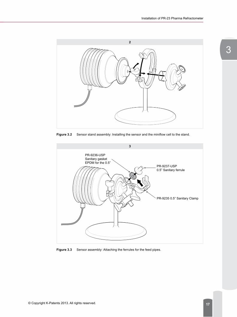
Attaching table top stand PR-7605-SS for Sensor and Miniflow cell Attach the 2.5” Sanitary clamp and the support rod to the base plate. The supplied screw (M5x16 A4 DIN 912) for attaching the stand is inserted from the bottom of the base plate through the bottom hole (Figure 3.1). To assemble the Pharma Miniflow cell first locate the PR-9244-USP O-ring 22.2x3.0 EPDM inside the Miniflow cell (Figure 3.2). Then insert the 2.5” Sanitary clamp for the sensor and mini flow cell.
Finally insert the two PR-9236-USP Sanitary EPDM gaskets and the two PR-9237 0.5” Sanitary ferrules for the inlet and outlet connectios using the two PR-9235 0.5” Sanitary Clamps.
Sensor can now be connected to flexible hoses and used as a free standing tabletop unit, see Figure 3.3.
1
Sanitary clamp and support
Base plate
Retaining screw
Sensor stand assembly
Figure 3.1 Sensor stand assembly: Attaching the clamp and support rod to the base plate.
Installation of PR-23 Pharma Refractometer
3
© Copyright K-Patents 2013. All rights reserved. 17
2
Figure 3.2 Sensor stand assembly: Installing the sensor and the miniflow cell to the stand.
3
PR-9237-USP 0.5” Sanitary ferrule
PR-9235 0.5” Sanitary Clamp
PR-9236-USP Sanitary gasketEPDM for the 0.5”
Figure 3.3 Sensor assembly: Attaching the ferrules for the feed pipes.
Document/Revision No. IM-GB-PR23-VACCINES: Rev. 1.01 Effective: November 1, 201318
Appendix to the Instructions Manual PR-23
4
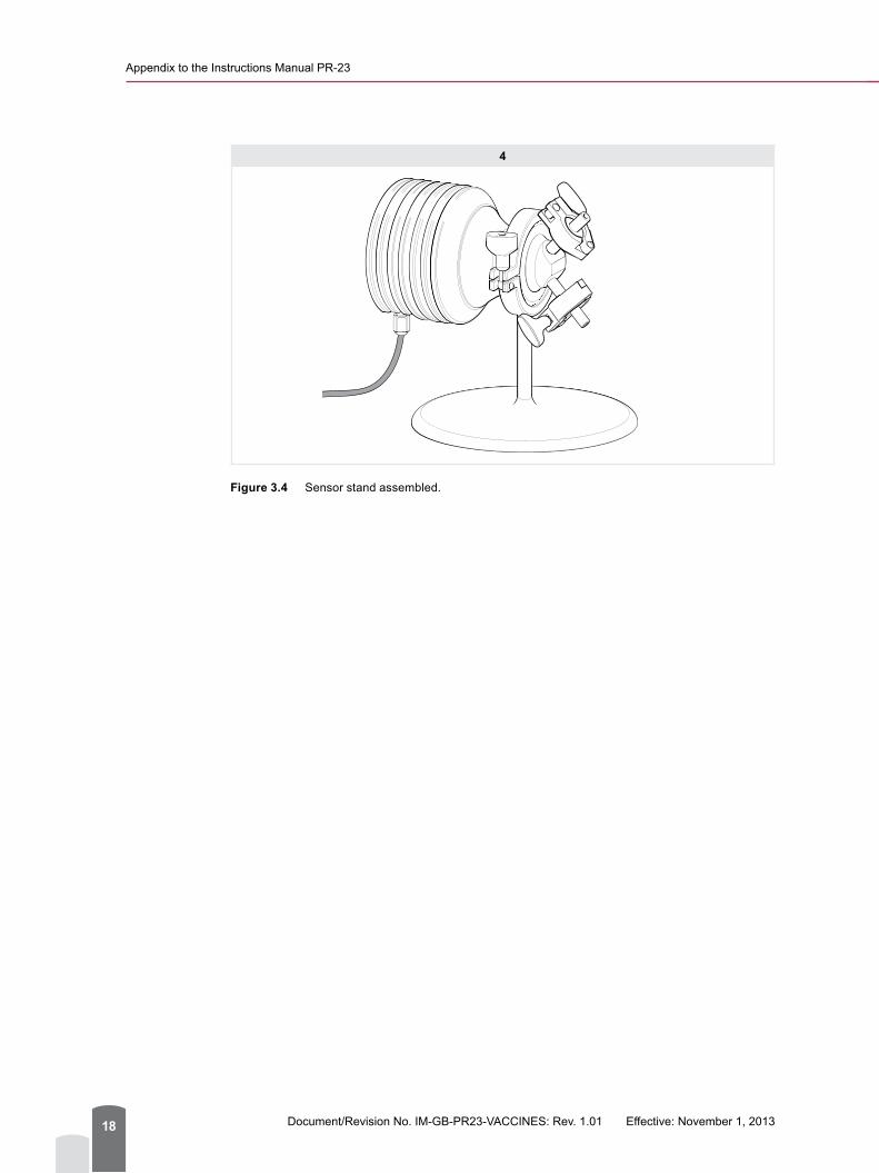
Figure 3.4 Sensor stand assembled.

Installation of PR-23 Pharma Refractometer
3
© Copyright K-Patents 2013. All rights reserved. 19
3.4 Indicating Transmitter installation for use in table top
Attaching table top stand PR-7603-SS for Indicating transmitter Unlock and open the transmitter cabinet door, then unscrew the retaining screw for the keypad panel and open the panel. The supplied screws (M5x10 A2 DIN 912) for attaching the stand are inserted from the inside through the top two holes located at the back of the cabinet. These are aligned and screwed into the threaded attachment points located at the top of the stand. The enclosure can now be used as a free standing tabletop unit, see Figure 3.2.
1
Figure 3.5 Attaching the laboratory table top stand to the Transmitter for use in the laboratory.

Document/Revision No. IM-GB-PR23-VACCINES: Rev. 1.01 Effective: November 1, 201320
Appendix to the Instructions Manual PR-23
3.5 Wiring transmitter connections to sensor, power cable and computer
For Indicating transmitter DTR wiring and Ethernet connections instructions see PROCESS REFRACTOMETER PR-23 INSTRUCTION MANUAL, Section 3 and Section 12. When the wiring connections have been made sensor calibration and verification can commence.
Pharma RefractometerPR-23-AC-62-HSS-EP
Pharma Mini Flow CellPMFC-HSS-EP
Crossover Cable
Interconnecting cablePR-8230
PC -Windows(not supplied by K-Patents)
Indicating TransmitterDTR-M-GP-SC
Power Supply Cable (not supplied by K-Patents)
Figure 3.6 Connection diagram

Installation of PR-23 Pharma Refractometer
3
© Copyright K-Patents 2013. All rights reserved. 21
3.6 Refractometer Instrument VerificationThe operational procedure checking the refractometer calibration accuracy, linearity and short-term repeatability and reproducibility consists of verification tests using Cargille standard Refractive index nD liquids.
The verification of the refractometer calibration is performed whenever a new K-Patents Laboratory Refractometer is qualified as a part of the validation process, and also if any of the following occurs:
● There is a replacement of optical parts (prism and prism gasket). ● Refractometer readings reflect an unusual shift, or are outside of the acceptable limits,
and other means of assessing and correcting unacceptable control values fail to identify and correct the problem.
Verification is recommended to be performed once every 12 months (or more frequently if specified in the client’s own quality system) as a routine quality control check. Verification is carried out using the Sample Holder PR-1012 and the set of Cargille standard refractive index nD liquids. A set (R.I. Liquid set PR-2300) is supplied by K-Patents. The Sample Holder PR-1012 consists of a sample receptacle with O-ring seal around the bottom aperture.
Before commencing the verification process make sure that your refractometer and sample holder are at normal room temperature. Preferably take all components to the laboratory already one day prior to the verification. Check the condition and expiry date of your Standard Refractive Index Liquids and that you also have the required cleaning solution (e.g. Isopropyl alcohol) and cleaning tissue to clean the sensor wetted surfaces and the sample holder.
For full Sensor verification instructions see PROCESS REFRACTOMETER PR-23, INSTRUCTION MANUAL Section 13.
After verification of the PR-23 sensor, further verification of the Laboratory Test Cuvette and Sensor combination can be carried out.

Document/Revision No. IM-GB-PR23-VACCINES: Rev. 1.01 Effective: November 1, 201322
Appendix to the Instructions Manual PR-23

© Copyright K-Patents 2013. All rights reserved. 23
4
4.1 Ethernet connectionIn addition to software operation via the hardware, the DTR can be considered as a web server and is accessible via a web-browser (e.g. Internet Explorer, Mozilla, Firefox etc.). The Ethernet connection enables data download from an Indicating transmitter DTR to a computer and replaces the traditional paper-based data collection methods and streamlines data collection. The connection works both directly between the DTR and a computer, or via a hub or a switch, local area network (LAN), wireless network (WLAN) or fiber Ethernet. Any type of computer (PC, Mac, PDA, mainframe…) with a compatible network connection can be configured to download data from the DTR.
For connecting and operating instructions of the Ethernet connection see PROCESS REFRACTOMETER PR-23 INSTRUCTION MANUAL Section 12.
4.2 Computer Communication Software CC-11The optional K-Patents Computer Communication Software CC-11 allows improved communication features. The CC-11 software is provided on a USB memory stick. The memory stick contains the software program: file name “CC-11”, folder name “data” for saving the data logging data and all files for functionality
When downloaded to a computer the CC-11 software makes it easy to set up and visualize real-time trend chart of the refractometer measurement values and diagnostic data on the computer screen. The data can be saved in PDF format to store the batch data over a selected period of time.
Connect the PR-8820 Crossover cable to the computer and plug the other end into the ethernet connection behind the transmitter key panel. For full connecting and operating instructions of the Ethernet connection see PROCESS REFRACTOMETER PR-23 INSTRUCTION MANUAL Section 12.
Electronic Data Capture and Storage

Document/Revision No. IM-GB-PR23-VACCINES: Rev. 1.01 Effective: November 1, 201324
Appendix to the Instructions Manual PR-23
Figure 4.1 Computer Communication software CC-11: Front page.
4.2.1 Installing Computer Communication software CC-11The Firewall settings on your computer can result in inability of the CC-11 program to activate the user interface. In order to change settings of the Firewall on your computer, open the Control Panel and choose Windows Firewall. Select Allow a program or feature through Windows Firewall. In the window press Change settings and then Allow another program. Open the log software file CC-11.exe by browsing to its position where it has been stored on the computer. Then press Add and in the ‘Name’ list CC-11 will appear. Tick all the given options and confirm by pressing OK.
4.2.2 Functionality and Main MenuWhen Computer Communicaton software CC-11 is installed in a computer and the Ethernet is connected to the DTR, measurement values and information about the connection are

Electronic Data Capture and Storage
4
© Copyright K-Patents 2013. All rights reserved. 25
displayed at all times. The IP address of the connected refractometer is displayed in the upper left corner. The color of the light in front of the IP address indicates the status of the connection.
Light Status of the connectionGreen CC-11 is connected to the refractometerYellow CC-11 is searching for the refractometerRed CC-11 is disconnected.
In the upper right corner, the name and Serial Number of the connected refractometer is displayed. If two sensors are connected to the CC-11 program, it is possible to display values for each sensor by pressing A or B. Concentration, refractive index nD and temperature will be displayed for the chosen sensor. Depending on the status of the refractometer, a status message will be displayed.
The main menu (Figure 4.2) provides access to the functions of the CC-11. The main menu consists of two colored selection buttons. The colored selection buttons can be used to:
− VIEW MEASUREMENT: view measurement data and status − DATA LOGGING: to log data into a log-file
Status of connection Sensor Serial Number
Access to functions
Measurement data
Sensor Diagnostic status
Figure 4.2 Computer Communication software CC-11: Functions and Main menu
4.2.3 Trend View MenuBy choosing either VIEW MEASUREMENT or DATA LOGGING measurement data can be viewed on a graph or logged into a PDF file. The logged data is date and time stamped indicating the logging starting and stopping dates and times.
The plotted measurement value can be changed by clicking on the grey area of the y-axis. The plotted measurement value can be either CALC, CONC, T or nD.
Document/Revision No. IM-GB-PR23-VACCINES: Rev. 1.01 Effective: November 1, 201326
Appendix to the Instructions Manual PR-23
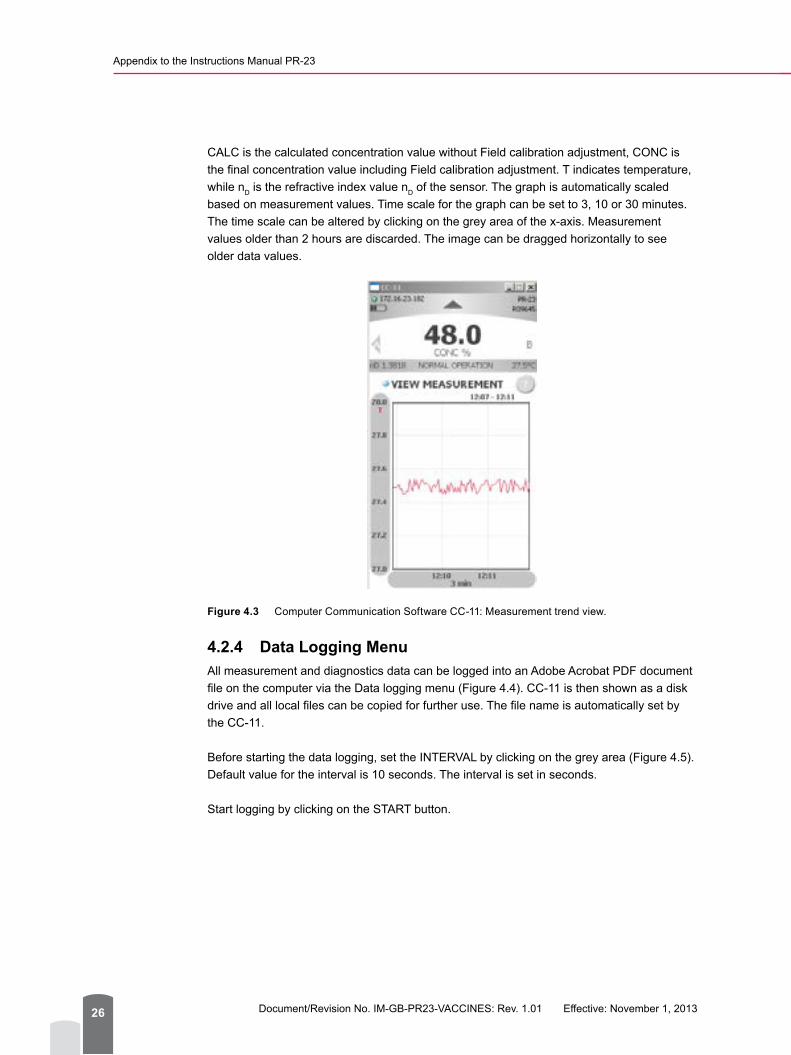
CALC is the calculated concentration value without Field calibration adjustment, CONC is the final concentration value including Field calibration adjustment. T indicates temperature, while nD is the refractive index value nD of the sensor. The graph is automatically scaled based on measurement values. Time scale for the graph can be set to 3, 10 or 30 minutes. The time scale can be altered by clicking on the grey area of the x-axis. Measurement values older than 2 hours are discarded. The image can be dragged horizontally to see older data values.
Figure 4.3 Computer Communication Software CC-11: Measurement trend view.
4.2.4 Data Logging MenuAll measurement and diagnostics data can be logged into an Adobe Acrobat PDF document file on the computer via the Data logging menu (Figure 4.4). CC-11 is then shown as a disk drive and all local files can be copied for further use. The file name is automatically set by the CC-11.
Before starting the data logging, set the INTERVAL by clicking on the grey area (Figure 4.5). Default value for the interval is 10 seconds. The interval is set in seconds.
Start logging by clicking on the START button.

Electronic Data Capture and Storage
4
© Copyright K-Patents 2013. All rights reserved. 27
Figure 4.4 Computer Communication Software CC-11: Data logging menu.
Figure 4.5 Computer Communication Software CC-11: Setting interval for data logging.

Document/Revision No. IM-GB-PR23-VACCINES: Rev. 1.01 Effective: November 1, 201328
Appendix to the Instructions Manual PR-23
The log file is not visible on the computer screen during the data logging, but the data file is saved in the local data folder and it can be opened and viewed after the logging has been stopped. The saved data file name indicates the sensor serial number and the date and time when the logging started (Figure 4.6).
Figure 4.6 Data logging file names.

© Copyright K-Patents 2013. All rights reserved. 29
5 Complying with Documentation and Validation Regulations
5.1 DocumentationWhen a pharmaceutical company purchases new measuring instruments, they must take into account the documentation requirements covered by national and international laws and directives, for example, the US Food and Drug Authority’s Code of Federal Regulations (CFR). FDA’s validation requirements leave it up to the manufacturer to determine what data is essential to prove control over their processes. Therefore, the requirements vary from company to company, and each pharmaceutical company is responsible for defining and maintaining its own documentation requirements list. Some areas to consider and their K-Patents solutions are presented in the sections below.
5.2 QualificationThe qualification action consists of proving and documenting that the equipment and ancillary systems are properly installed, operating correctly, and producing verified results. Qualification is a part of the validation process, but the individual qualification stages alone do not constitute process validation.
Installation Qualification, Operational Qualification and Performance Qualification protocols are normally required to document that the correct refractometer model and parts have been ordered, delivered and installed according to K-Patents’ recommendations, and also to check that the refractometer meets its performance specification and is able to reliably measure typical samples using the selected measurement method. Users are able to create their own protocols using the relevant information from this manual appendix and the product manual, and/or using their own templates. The complete qualification process must be fully documented.
5.3 Protocol Acceptance by Customer and List of Tests Performed
A qualification protocol which provides details about the system, the scope and constraints of the qualification, the qualification tests, test procedures and acceptance criteria should be available for review and approval before the qualification begins. The protocol should also contain an exception log to record any out of the specification results, investigation and problem resolution. After the qualification, the test results must be reviewed and approved before the instrument can be put into routine use.

Document/Revision No. IM-GB-PR23-VACCINES: Rev. 1.01 Effective: November 1, 201330
Appendix to the Instructions Manual PR-23
5.4 Electronic Data Management and Data StorageThe Code of Federal Regulations (CFR) FDA 21, Part 11 requires that pharmaceutical companies use electronic (i.e. software-maintained) data recording and storage, rather than paperwork. In case of instrument measurements, the code requires that every reading taken with the instrument must be logged and permanently stored electronically, and the data is password-protected ensuring alteration accountability (i.e. which operator makes an alteration) and tracking.
Part 11 describes four basic system elements that must be addressed. They are: ● Electronic signatures and tracking ● Data storage and logs ● Security ● System validation.
5.5 Electronic Signatures/Audit TrailData records must be linked to the relevant electronic signatures so that when accessed, either electronically or through printout, the signatures will be openly displayed along with the date and time of execution.
5.6 Record KeepingData records must be stored in a format that the FDA can reasonably expect to be able to read. These records must be retained for the length of time required by the predicate rule.
5.7 SecuritySystem access can be restricted to authorized individuals using the lock on the Indicating transmitter door and password-protected access to the indicating transmitter and to the computer. There are also four input switches behind the front panel of the indicating transmitter. The input switch can be configured to seal the calibration and to prevent access to the calibration and to configuration, see PROCESS REFRACTOMETER PR-23 INSTRUCTION MANUAL, Section 6.4.
The actions of these authorized individuals in relation to the data must be openly accounted for throughout the audit trail.
5.8 System ValidationThe system must be validated to prove that it complies with the technical requirements of Part 11. The Installation Qualification, Operation Qualification, and Performance Qualification (IQ/OQ/PQ) should also be performed.

Complying with Documentation and Validation Regulations
5
© Copyright K-Patents 2013. All rights reserved. 31
5.9 K-Patents Refractometer System Adherence to Part 11
It is not possible to supply a system readily in compliance with Part 11. This is because the requirements of Part 11 fall into two categories: those that are handled technically (through software features), and those that are handled procedurally (such as through system validation, SOPs, policies, etc.).
Part 11 applies to all computerized systems that create, modify, maintain, archive, or retrieve records required by the FDA. K-Patents Pharma Refractometer generates electronic records via Ethernet connection. These records can be stored as digital files and printed out for signature or filed and maintained as hard copies. The computer files are subject to Part 11 regulation. The instrument parameter and configuration changes also fall into this category.
These computer files may be used in either of the two ways:1. as a non-subject system by printing results, signing by hand, and maintaining
hard copies2. as an electronic record-keeping system subject to Part 11 regulation.
Systems described by number 1 would be subject only to predicate rules, not Part 11. Systems described by number 2 must comply with Part 11.
Please note: While K-Patents has taken account of the FDA Part 11 rules during development of the Pharma Refractometer package and in the compilation of the instructions and guidelines contained in this Instruction manual appendix, the system described has not been approved or mandated by the FDA or any other government agencies. So all compliance responsibility lies with the end user and K-Patents makes no claims that the completion of all the procedures described here will exempt these companies or individuals from FDA sanctions.

Document/Revision No. IM-GB-PR23-VACCINES: Rev. 1.01 Effective: November 1, 201332
Appendix to the Instructions Manual PR-23

© Copyright K-Patents 2013. All rights reserved. 33
6
This Installation Qualification (IQ) involves documented verification of the complete system: K-Patents Pharma Refractometer PR-23-AC and Pharma Mini flow cell PMFC-HSS with Ethernet connection, as installed and connected to a fractionation unit and a computer, and in compliance with the approved design, the manufacturer’s recommendations and user requirements.
6.1 Authorization and responsibilities
6.1.1 Documents and proceduresThe following documents and procedures are inspected:
● Scope and Procedure for Qualification ● Report on Installation Qualification ● Protocol for Installation Qualification
The authorized official (client) hereby declares that the execution of the Installation Qualification (IQ) for the Pharma Refractometer and Pharma Mini flow cell have been approved in accordance with this document/log. The authorized official is responsible for all relevant matters in regard to the installation qualification.
Release by superior department:
Name:
Function:
Date:
Signature:
Initials:
Authorization by a higher-level authority is a prerequisite for carrying out the qualification procedure. If no valid written authorization is available, terminate the Installation Qualification.
Onsite Qualification Protocols and Records: Installation Qualification

Document/Revision No. IM-GB-PR23-VACCINES: Rev. 1.01 Effective: November 1, 201334
Appendix to the Instructions Manual PR-23
6.1.2 Authorized officiatorSelection of the individual authorized to carry out the Installation Qualification of the Pharma Refractometer system should be in accordance to their relevant ability to undertake the procedure. The authorized officiator’s signature is required for the next stage to validate Date/Initials in the Installation Qualification log and reports.
Name:
Function:
Date:
Signature:
Initials:
6.1.3 ExecutionAs it is executed, each described step of the Installation Qualification requires initialing and dating. If any deviations occur, the qualification must either be aborted or a detailed explanation of the deviations must be entered in the subsequent “Deviation, evaluation, corrective actions” logs and must be documented appropriately.
6.2 System
6.2.1 Qualifying the systemLocation of the Pharma Refractometer Sensor and Pharma Mini flow cell:
Location of the Indicating Transmitter:
Device Serial Number Supplier Manufacturer
Pharma Refractometer: Sensor PR-23-AC-62-HSS
K-Patents Oy
Pharma Refractometer: Indicating transmitter DTR-M/U-GP-SC
K-Patents Oy
Computer
Onsite Qualification Protocols and Records: Installation Qualification
6
© Copyright K-Patents 2013. All rights reserved. 35
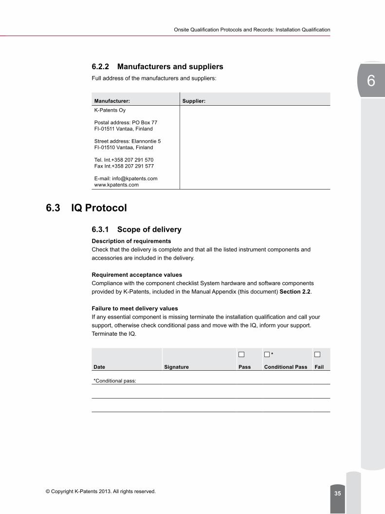
6.2.2 Manufacturers and suppliersFull address of the manufacturers and suppliers:
Manufacturer: Supplier:
K-Patents Oy
Postal address: PO Box 77FI-01511 Vantaa, Finland
Street address: Elannontie 5FI-01510 Vantaa, Finland
Tel. Int.+358 207 291 570Fax Int.+358 207 291 577
E-mail: [email protected]
6.3 IQ Protocol
6.3.1 Scope of deliveryDescription of requirementsCheck that the delivery is complete and that all the listed instrument components and accessories are included in the delivery.
Requirement acceptance valuesCompliance with the component checklist System hardware and software components provided by K-Patents, included in the Manual Appendix (this document) Section 2.2.
Failure to meet delivery valuesIf any essential component is missing terminate the installation qualification and call your support, otherwise check conditional pass and move with the IQ, inform your support. Terminate the IQ.
Date Signature Pass
*
Conditional Pass Fail
*Conditional pass:

Document/Revision No. IM-GB-PR23-VACCINES: Rev. 1.01 Effective: November 1, 201336
Appendix to the Instructions Manual PR-23
6.3.2 DamageDescription of requirementsInspection of all components and devices to check they are undamaged and functional.
Damage or malfunction detectedTerminate the IQ.
Report to:
Date Signature Pass
*
Conditional Pass Fail
*Conditional pass:
6.4 DocumentationDescription of requirementsMake sure that the Operating Instructions and all other required documentation are complete and accessible.
Type of document Document/Revision No.
Requested
Present Missing Not requested
Instruction Manual for Inline Refractometer PR-23(-...-AX/FM/CS/IA/IF)
IM-GB-PR23
Appendix to Instruction Manual
IM-GB-PR23-AC-VACCINES: Rev. 1.0
Operating Manual for:
Material Safety Data Sheet for Cargille Refractive Index Liquids
Date Signature Pass
*
Conditional Pass Fail
*Conditional pass:

Onsite Qualification Protocols and Records: Installation Qualification
6
© Copyright K-Patents 2013. All rights reserved. 37
6.5 Operating environmentDescription of requirementsEnsuring that the appropriate power supply and power switch are available.
Requirement acceptance valuesAn electrical power supply with a voltage and frequency of 100-230 VAC/50-60 Hz (Optional 24 VDC). A computer (PC, Mac, PDA or mainframe).
Failure to meet any of the acceptance valuesA new environment must be established and the qualification performed again from Section 6.3.1 (of this document) onwards.
Date Signature Pass
*
Conditional Pass Fail
*Conditional pass:
6.6 InstallationRequirement descriptionThe authorized operator who in accordance with Section 6.2 (of this document), must read the installation instructions in Section 3 (of this document).
Requirement acceptance valuesThe relevant sections have been read.
Date Signature Pass
*
Conditional Pass Fail
*Conditional pass:
Document/Revision No. IM-GB-PR23-VACCINES: Rev. 1.01 Effective: November 1, 201338
Appendix to the Instructions Manual PR-23
6.7 Setting up the system components and devicesDescription of requirementsThe Pharma Refractometer system with Refractometer sensor, Pharma mini flow cell and Indicating transmitter, are assembled and mounted correctly as described in the Section 3 (this document). Also the ancillary sample system is connected in accordance with the Section 3 (this document). The ancillary equipment is switched on in accordance with the corresponding operating manuals.
Requirement acceptance valuesThe system and devices are complete and have been set up in compliance with the instructions.
Failure to meet the acceptance valuesTerminate the IQ.
Date Signature Pass
*
Conditional Pass Fail
*Conditional pass:

Onsite Qualification Protocols and Records: Installation Qualification
6
© Copyright K-Patents 2013. All rights reserved. 39
6.8 Electrical connections and wiringDescription of requirementsThe frequency of the power supply must match the frequency indicated on the instrument’s rating plate. The electrical wiring connections have been connected in accordance with the instructions laid down in the PROCESS REFRACTOMETER PR-23 INSTRUCTION MANUAL Section 12.
Requirement acceptance valuesAll electrical wiring connections have been connected in compliance with the instructions laid down in the PROCESS REFRACTOMETER PR-23 INSTRUCTION MANUAL Section 12.
Date Signature Pass
*
Conditional Pass Fail
*Conditional pass:
Description of requirementsEthernet connections and wiring have been connected and set up in accordance with the PROCESS REFRACTOMETER PR-23 INSTRUCTION MANUAL Section 12.
Requirement acceptance valuesThe Ethernet connections comply with the PROCESS REFRACTOMETER PR-23 INSTRUCTION MANUAL Section 12.
Date Signature Pass
*
Conditional Pass Fail
*Conditional pass:

Document/Revision No. IM-GB-PR23-VACCINES: Rev. 1.01 Effective: November 1, 201340
Appendix to the Instructions Manual PR-23
6.9 Ethernet connectionDescription of requirementsEthernet connections and wiring have been connected and set up in accordance with the PROCESS REFRACTOMETER PR-23 INSTRUCTION MANUAL Section 12.
Requirement acceptance valuesThe Ethernet connections comply with the PROCESS REFRACTOMETER PR-23 INSTRUCTION MANUAL Section 12.
Date Signature Pass
*
Conditional Pass Fail
*Conditional pass:
6.10 Computer communication software CC-11Description of requirementsComputer communication software has been intalled on a computer in accordance with the Section 4.2 (this document).
Requirement acceptance valuesThe Ethernet connections and Computer communication software comply with the PROCESS REFRACTOMETER PR-23 INSTRUCTION MANUAL Section 12 and Section 4.2 (this document).The corresponding computer screen displays occur in accordance with the Section 4.2 (this document).
Date Signature Pass
*
Conditional Pass Fail
*Conditional pass:
6.11 Initial check and switching the device on Description of requirementsThe initial check has been performed and the electrical power has been connected in accordance with the PROCESS REFRACTOMETER PR-23 INSTRUCTION MANUAL Section 5.1.1.
Onsite Qualification Protocols and Records: Installation Qualification
6
© Copyright K-Patents 2013. All rights reserved. 41
Requirement valuesThe corresponding screen displays occur in accordance with the PROCESS REFRACTOMETER PR-23 INSTRUCTION MANUAL Section 5.1.1.
Failure to meet acceptance valuesTerminate the IQ.
Date Signature Pass
*
Conditional Pass Fail
*Conditional pass:

Document/Revision No. IM-GB-PR23-VACCINES: Rev. 1.01 Effective: November 1, 201342
Appendix to the Instructions Manual PR-23
6.12 Installation Qualification Summary ReportSuccessful completion of the preceding activities and checks indicates that this instrument has been satisfactorily delivered and installed. This instrument has passed the Installation Qualification and may now be submitted for Operational Qualification.
IQ completed by
Name:
Function:
Date:
Signature:
Signature:
IQ deviations approved by
Name:
Function:
Date:
Signature:
Signature:
IQ approved by
Name:
Function:
Date:
Signature:
Signature:
Comments (including discrepancies)

© Copyright K-Patents 2013. All rights reserved. 43
7 Onsite Qualification Protocols and Records: Operational Qualification
Operational Qualification (OQ) is documented verification stating that the equipment and systems, as installed for the first time or after repairs and major incidents, perform as intended throughout the required operating ranges. The OQ is to ensure that the K-Patents Pharma refractometer meets predefined specifications, and all system components function correctly and according to specifications within a specific environment.
7.1 Individual module and system components checkChecking the operation of the refractometer as an individual module, and as a system that comprises also of the Pharma mini flow cell, the Computer, the Ethernet connection, the Computer communication software and Ancillary equipment such as fractionation unit.
● Operational check on the Refractometer consists of Refractive index nD accuracy, linearity and short-term repeatability and reproducibility verification tests with Cargille standard refractive index nD liquids.
● In addition to the system components, testing functional challenge, testing the system software operation, should be conducted.
● Stage by stage operational procedure checking. A pre-determined set of instructions can be input stage by stage into the system. The system responses are then compared to the expected outcome of the instructions to determine any problems in their fulfillment.
● Sign off when successfully completed.
7.2 Installation Qualification has been performed successfully
Description of RequirementAn Installation Qualification has been performed for the system.
Requirement Acceptance valuesThe Installation Qualification has been carried out successfully with the required approval.
Date of Installation Qualification:
Performed by:
Do not proceed with the Operational Qualification until a valid Installation Qualification has been successfully completed and signed off.

Document/Revision No. IM-GB-PR23-VACCINES: Rev. 1.01 Effective: November 1, 201344
Appendix to the Instructions Manual PR-23
7.3 Test procedureThe Operational Qualification of the system is performed in accordance with a set plan in which the following points are tested and documented sequentially:
● The required documents, measuring instruments, refractive index liquids, and required cleaning materials are available
● Functional checks and verification of the refractometer performance ● Functional checks have been made for the ancillary equipment.
The authorized official (client) hereby declares that the performance of the Operational Qualification (OQ) for the Pharma Refractometer and Pharma mini flow cell has been approved in accordance with this document/protocol. The authorized official is responsible for all relevant matters in regard to the operational qualification.
Release by superior department:
Name:
Function:
Date:
Signature:
Initials:
Authorization by a higher-level authority is a prerequisite for carrying out the qualification procedure. If no valid written authorization is available, terminate the Operational Qualification.
7.4 Authorized officiatorSelection of the individuals authorized to carry out the Operational Qualification of the Pharma Refractometer system should be in accordance with their relevant ability to undertake the procedure. The authorized officiator’s signature is required for the next stage to validate Date/Initials in the Operational Qualification log and reports.
Name:
Function:
Date:
Signature:
Initials:

Onsite Qualification Protocols and Records: Operational Qualification
7
© Copyright K-Patents 2013. All rights reserved. 45
7.5 System qualificationCheck that the system is the same as defined in the IQ, with no changes.
Definition of requirementsAll system equipment remains the same as for the IQ and the ancillary equipment IQ is valid.
Date Signature Pass Conditional Pass Fail
Conditional pass:
7.6 Setting up the system components and devicesDescription of requirementsThe Pharma Refractometer system comprised of Refractometer sensor, Pharma mini flow cell and Indicating transmitter, is assembled and mounted correctly as described in the Section 3 (this document). Initial startup checks for the Refractometer have been made according to PROCESS REFRACTOMETER PR-23 INSTRUCTION MANUAL, Section 5. Also the ancillary fractionation unit and the sample delivery system (if required) are connected and the ancillary equipment is switched on and functional checks are made in accordance with the corresponding operating manuals.
Requirement acceptance valuesThe system and devices are complete and have been set up in compliance with the instructions.
Failure to meet any of the acceptance valuesTerminate the OQ.
Date Signature Pass Conditional Pass Fail
Conditional pass:

Document/Revision No. IM-GB-PR23-VACCINES: Rev. 1.01 Effective: November 1, 201346
Appendix to the Instructions Manual PR-23
7.7 Instrument verification with Sample holder and Refractive Index Liquids
Description of requirementsRefractometer, sample holder PR-1012 and a set of five standard Refractive index liquids PR-2300 with Cargille Certification are allowed to be settled to laboratory ambient temperature (between 20-30 °C, 77-86°F) 24 hours prior to commencement of the qualification.
Requirement acceptance valuesRefractometer, sample holder and Refractive index liquids positioned in the laboratory 24 hours prior to verification with the ambient temperature at between 20-30 °C (77-86°F).
Date Signature Pass Conditional Pass Fail
Conditional pass:
Description of requirementsThe procedure is done with all five liquids using a sample holder and verification instructions at PROCESS REFRACTOMETER PR-23 INSTRUCTION MANUAL, Section 13.
Nominal R.I. values: ● 1.330 ● 1.370 ● 1.420 ● 1.470 ● 1.520
Requirement valuesThe verification results are OK for all samples and acceptance / deviation values (not more than + 0.0004 of the nominal values) are received for each sample. The Instrument verification page in the browser for the complete Verification test procedure shows Verification result: pass.
Failure to meet acceptance valuesTerminate the OQ.
Date Signature Pass Conditional Pass Fail
Conditional pass:

Onsite Qualification Protocols and Records: Operational Qualification
7
© Copyright K-Patents 2013. All rights reserved. 47
7.8 Operational Qualification Summary ReportSuccessful completion of the preceding activities and checks indicates that this instrument performs satisfactorily. The Operational Qualification has been accepted.
OQ completed by
Name:
Function:
Date:
Signature:
Signature:
OQ deviations approved by
Name:
Function:
Date:
Signature:
Signature:
OQ approved by
Name:
Function:
Date:
Signature:
Signature:

Document/Revision No. IM-GB-PR23-VACCINES: Rev. 1.01 Effective: November 1, 201348
Appendix to the Instructions Manual PR-23
Comments (including discrepancies)

© Copyright K-Patents 2013. All rights reserved. 49
8
After the instrument is qualified, it can be used to measure analytical data. A Standard Operating Procedure (SOP) has to be written for the new instrument. Operational instructions, maintenance and calibration should be included in the SOP. It is unnecessary to copy the complete operation manual into the SOP. Writing down simple instructions referencing the related manual sections is more effective. The particular tasks and the frequency they should be performed during maintenance should be clearly stated in the maintenance section. Tests required to verify the instrument, the acceptance criteria and the frequency for each test should be covered in the calibration section of the SOP.
Definitions of major and minor repairs, which necessitate partial or full system re-qualification, should be included as well. For example, the replacement of a Teflon pad in the sample mixer does not require a full re-qualification. Replacement of optical parts (Prism) will warrant full re-qualification.
Good system maintenance starts with the users. Proper care, which can be as simple as a good system rinsing and clean up after use, will reduce the possibility of system failure during runs and will extend the useful life of the instrument.
Maintain good usage and service records for the instrument for Good Manufacturing Practice (GMP) purposes. Records of usage allow the users to be alerted to any system or instrument calibration failure. The user may have to do an impact assessment to determine whether the failure would have affected the reliability of the results generated by the system. The service records will also provide useful information about the system, which may simplify trouble shooting in some cases.
The GMP requirements dictate that the refractometer calibration verification (see Section 3.1) should be performed at suitable intervals in accordance with an established schedule. Any instrument failing to meet established specifications shall not be used. Each K-Patents Pharma Refractometer is recommended to have a calibration verification label applied with the relevant status information on the system, date of the last calibration verification, who carried out the verification and the scheduled date for the next verification.
Routine Operation Phase

Document/Revision No. IM-GB-PR23-VACCINES: Rev. 1.01 Effective: November 1, 201350
Appendix to the Instructions Manual PR-23

© Copyright K-Patents 2013. All rights reserved. 51
9
The need for K-Patents Pharma Refractometer regular maintenance is minimal, due to the construction with no moving parts, no mechanical adjustments, no trimpots and with a solid-state light source, see Section 7, PROCESS REFRACTOMETER PR-23 INSTRUCTION MANUAL.
The following checks should be performed for Mini flow cell at suitable intervals in accordance with an established schedule:
● Check the condition of the O-ring (PR-9244-USP O-ring 22.2x3.0 EPDM) of the Pharma Mini Flow Cell
● Check the condition of the two Sanitary gaskets (PR-9236-USP EPDM) of the 0.5” Sanitary Clamps
Preventive Maintenance

Document/Revision No. IM-GB-PR23-VACCINES: Rev. 1.01 Effective: November 1, 201352
Appendix to the Instructions Manual PR-23

© Copyright K-Patents 2013. All rights reserved. 53
10Other Documentation
You may want to include the following documents in your files concerning this K-Patents instrument:
● Delivery Data Sheet (supplied with the instrument) ● Certificate of Traceability for Standard Refractive Index liquids
(supplied with the liquids PR-2300) ● Material Traceability Certificate of Compliance in accordance with EN 1024-3.1b.
Note: This document is delivered on request and it must be specified when ordering. ● K-Patents ISO 9001 certificate
(can be obtained from www.kpatents.com ► Documents downloads)

Notes
Appendix to the Instructions Manual PR-23
Document/Revision No. IM-GB-PR23-VACCINES: Rev. 1.0 Effective: March 1, 201354


www.kpatents.com
K-Patents OyP.O. Box 77FI-01511 Vantaa, FinlandTel: +358 207 291 570Fax: +358 207 291 577Email: [email protected]
K-Patents, Inc.1804 Centre Point Circle, Suite 106Naperville, IL 60563, USATel: (630) 955 1545Fax: (630) 955 1585Email: [email protected]
K-Patents (Shanghai) Co, Ltd17-05H, 17F, Times Square , No. 500Zhang Yang RoadPudong District, Shanghai, ChinaTel. +86 21 5178 2775Fax +86 21 5178 2799


![Instruction manual for Vaisala K-PATENTS process refractometer PR-23 · 2020-02-13 · Wh >/^, z s] oKÇi svZEµ u]i À v îíU &/rìíòóì sv U &]vov WXKX }Æ îòU &/rììðîí](https://static.fdocuments.us/doc/165x107/5f9d13f07eb60b75f5614b4b/instruction-manual-for-vaisala-k-patents-process-refractometer-pr-23-2020-02-13.jpg)


