2.0 DESCRIPTION OF THE PROPOSED ACTION DESCRIPTION OF THE PROPOSED ACTION Broadwater proposes to...
43
2-1 2.0 DESCRIPTION OF THE PROPOSED ACTION Broadwater proposes to construct, install, operate, and maintain a new marine LNG terminal and new subsea pipeline for importation, storage, vaporization, and transportation of natural gas. LNG would be imported by LNG carrier from one or more of the 20 LNG export terminals located in South America, Africa, the Middle East, and Southeast Asia. This section describes the Proposed Action, including the following: • Proposed facilities (Section 2.1); • Land and surface requirements (Section 2.2); • Construction procedures (Section 2.3); • Operation and maintenance (Section 2.4); • Schedule (Section 2.5); • Environmental compliance inspection and mitigation monitoring (Section 2.6); and • Future plans and abandonment (Section 2.7). 2.1 PROPOSED FACILITIES The proposed Broadwater LNG terminal would be in New York State waters of Long Island Sound, approximately 9 miles 1 from the nearest shoreline of Long Island, as shown in Figure 2.1-1. The LNG terminal would be an FSRU that would be attached to a YMS that includes a mooring tower embedded in the sea floor. LNG, which would be delivered to the FSRU by LNG carriers, would be stored and vaporized (regasified) on the FSRU. The Project also would include a new natural gas pipeline, extending from the seafloor beneath the FSRU to an offshore connection with the existing IGTS pipeline. Natural gas would be routed from the FSRU to the subsea pipeline and into the IGTS pipeline for delivery to customers south of the FSRU (Long Island and New York City) and north of the FSRU (primarily Connecticut). All Project-related facilities would be located within Suffolk County, New York. The following sections describe the proposed FSRU (Section 2.1.1), YMS (Section 2.1.2), pipeline and associated facilities (Section 2.1.3), and LNG carriers (Section 2.1.4). 2.1.1 FSRU This section provides an overview of the key features of the FSRU and descriptions of the major equipment on the FSRU, including LNG storage tanks, berthing and unloading facilities, vaporization facilities, and major support facilities and systems. 1 In this EIS, miles are reported as statute miles. One statute mile is equivalent to approximately 0.9 nautical mile; 1 nautical mile is approximately 1.2 statute miles.
Transcript of 2.0 DESCRIPTION OF THE PROPOSED ACTION DESCRIPTION OF THE PROPOSED ACTION Broadwater proposes to...

2-1
2.0 DESCRIPTION OF THE PROPOSED ACTION
Broadwater proposes to construct, install, operate, and maintain a new marine LNG terminal and new subsea pipeline for importation, storage, vaporization, and transportation of natural gas. LNG would be imported by LNG carrier from one or more of the 20 LNG export terminals located in South America, Africa, the Middle East, and Southeast Asia. This section describes the Proposed Action, including the following:
• Proposed facilities (Section 2.1);
• Land and surface requirements (Section 2.2);
• Construction procedures (Section 2.3);
• Operation and maintenance (Section 2.4);
• Schedule (Section 2.5);
• Environmental compliance inspection and mitigation monitoring (Section 2.6); and
• Future plans and abandonment (Section 2.7).
2.1 PROPOSED FACILITIES
The proposed Broadwater LNG terminal would be in New York State waters of Long Island Sound, approximately 9 miles1 from the nearest shoreline of Long Island, as shown in Figure 2.1-1. The LNG terminal would be an FSRU that would be attached to a YMS that includes a mooring tower embedded in the sea floor. LNG, which would be delivered to the FSRU by LNG carriers, would be stored and vaporized (regasified) on the FSRU. The Project also would include a new natural gas pipeline, extending from the seafloor beneath the FSRU to an offshore connection with the existing IGTS pipeline. Natural gas would be routed from the FSRU to the subsea pipeline and into the IGTS pipeline for delivery to customers south of the FSRU (Long Island and New York City) and north of the FSRU (primarily Connecticut). All Project-related facilities would be located within Suffolk County, New York.
The following sections describe the proposed FSRU (Section 2.1.1), YMS (Section 2.1.2), pipeline and associated facilities (Section 2.1.3), and LNG carriers (Section 2.1.4).
2.1.1 FSRU
This section provides an overview of the key features of the FSRU and descriptions of the major equipment on the FSRU, including LNG storage tanks, berthing and unloading facilities, vaporization facilities, and major support facilities and systems.
1 In this EIS, miles are reported as statute miles. One statute mile is equivalent to approximately 0.9 nautical mile; 1 nautical mile is approximately 1.2 statute miles.

Figure 2.1-1Broadwater LNG Project
Proposed Project Location
!.
!
!
!
!
!
!
!
!
!
!
!
!
!
!
!
!
!
!
!
!
!
!
!
!
!
!
!
!
!
!
!
!
!
!!
!
!
!
!
!(
!(
C o n n e c t i c u tN e w Y o r k
N e w J e r s e y
N e w Y o r k
R h o d e I s l a n d
A t l a n t i c O c e a n
B l o c k I s l a n dS o u n d
Tolland Co
Ulster Co
Block Island
L o n g I s l a n d S o u n d
Monmouth Co
L o n g I s l a n d
New York
New YorkConnecticut
IGTS
Eastern BasinCentral
Basin
WesternBasin
The Narrows
The Race
Port Jefferson
Rhode IslandMontauk Channel
Stratf
ord Sh
oal Ma
ttituc
k Sill
Suffolk Co
Orange Co
Litchfield CoHartford CoDutchess Co
Fairfield Co
New London Co
New Haven Co
Windham Co
Westchester Co
Middlesex Co
Nassau Co
Middlesex Co
Bergen Co
Putnam CoWashington Co
Kent Co
Rockland Co
Queens Co
Kings Co
Bronx Co
Rye
Hamden
DarienSprings
Madison
Norwalk
Niantic
Milford
Clinton
Montauk
Shoreham
Branford
Stamford
Bayville
Westbrook
Stratford
Southport
New Haven
Greenwich
Fairfield
Smithtown
Riverhead
Greenport
Asharoken
New London
West Haven
Bridgeport
Manorhaven
Mamaroneck
Kings ParkHuntington
Stony Brook
Orient Point
East Northport
¯ 0 7 14 21 283.5Miles
!. Proposed FSRU Location!( Proposed Onshore Facilities Location
Proposed Broadwater Pipeline RouteIGTS PipelineState LineBasin Boundaries
71°3
0'0"W
72°0
'0"W72
°30'0
"W
73°0
'0"W
73°3
0'0"W
74°0
'0"W
41°30'0"N
41°0'0"N
40°30'0"N
2-2

2-3
2.1.1.1 Overview of the FSRU
The FSRU would resemble a marine vessel, both in appearance and design, and would remain moored in place for the duration of the Project. It would be approximately 1,215 feet long and 200 feet wide, with a draft of approximately 40 feet. The FSRU would not be self-propelled but would be equipped with a pair of stern thrusters to assist when required to maintain a constant heading during mooring operations with LNG carriers.
The main deck of the FSRU would be approximately 48 feet above the water line, with a “trunk deck” extending about 34 feet above the main deck to support some of the process equipment. Figure 2.1-2 depicts the layout of the primary equipment on the FSRU, and Figure 2.1-3 provides the distances above the water line for these major structures. During operation, the water line would remain at about the same level on the FSRU as a result of ballasting operations during unloading of both the LNG carriers and the storage tanks on the FSRU. LNG storage tanks would be located below the decks and would not be visible. To enhance physical protection of the LNG storage area, the FSRU would be double-hulled on all sides in a manner similar to LNG carriers. The FSRU would be connected to a YMS installed at a water depth of approximately 90 feet. The YMS would allow the FSRU to pivot or “weathervane” around the YMS, enabling the vessel to orient in response to the prevailing wind, tide, and current conditions. Weathervaning would also occur when LNG carriers are moored to the FSRU.
The FSRU would be designed to accommodate storage of up to approximately 8 bcf (350,000 m3) of LNG, with base vaporization capabilities of 1.0 bcfd and a maximum output of 1.25 bcfd, using a closed-loop shell-and-tube vaporization (STV) system. LNG would be delivered in LNG carriers with cargo capacities ranging from 125,000 to 250,000 m3. From two to three LNG carriers per week (104 to 156 carriers per year) would arrive at the FSRU, with an anticipated average of 118 carriers per year.
A single carrier berth would be on the starboard side (right side if facing to the front [bow]) of the FSRU, along with unloading arms and other LNG unloading equipment and facilities. Living quarters to accommodate 30 permanent and 30 temporary (during commissioning, training, shutdowns, and maintenance) crew members would be included on the aft end (stern or rear) of the FSRU.
Broadwater has indicated that final design and material specifications for the FSRU would be determined in consultation with a ship classification society. Classification societies are organizations that develop and apply design, construction, and maintenance rules for ships and offshore structures. These rules apply to the strength and integrity of a vessel or the structure’s hull and appendages, and the reliability of steering, power generation, and other systems needed to maintain essential services. Classification societies rely on the review and opinions of industry experts.
Vessels and structures designed and constructed to the rules of a classification society may be issued a Certificate of Classification from that society, following a series of pre- and post-construction classification surveys to verify compliance with applicable rules.
The American Bureau of Shipping (ABS), a classification society, has reviewed preliminary design plans for the proposed Broadwater FSRU and has agreed that the FSRU can be reviewed and classified in accordance with ABS rules. Elements of the FSRU that will be reviewed for ABS classification include the hull and containment systems, mooring system, LNG loading and regasification systems, natural gas sendout pipeline, crew accommodations, hazardous material handling and storage systems, and other facilities and systems of the FSRU.
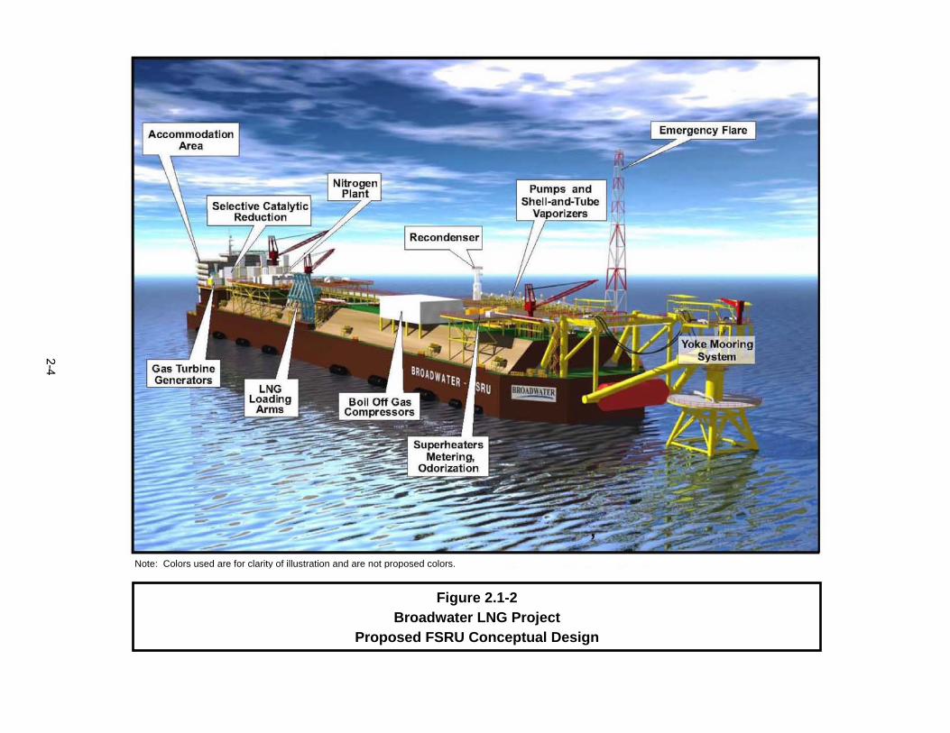
Note: Colors used are for clarity of illustration and are not proposed colors.
Figure 2.1-2Broadwater LNG Project
Proposed FSRU Conceptual Design
2-4

Figure 2.1-3Broadwater LNG Project
Approximate Heights above Water for Primary FSRU Components
Source: Saratoga Associates 2005 Note: Colors are used for clarity of illustration and are not proposed colors; distances listed are height above water line at SPECIFIED loading.
2-5
2-6
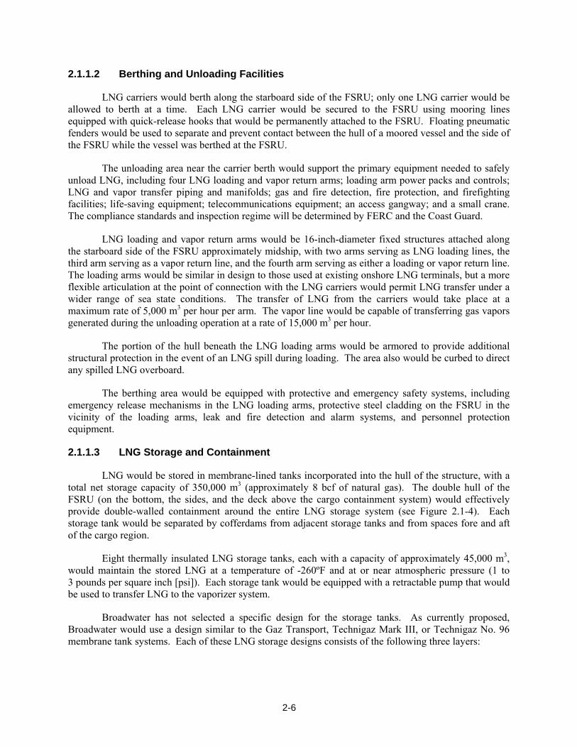
2.1.1.2 Berthing and Unloading Facilities
LNG carriers would berth along the starboard side of the FSRU; only one LNG carrier would be allowed to berth at a time. Each LNG carrier would be secured to the FSRU using mooring lines equipped with quick-release hooks that would be permanently attached to the FSRU. Floating pneumatic fenders would be used to separate and prevent contact between the hull of a moored vessel and the side of the FSRU while the vessel was berthed at the FSRU.
The unloading area near the carrier berth would support the primary equipment needed to safely unload LNG, including four LNG loading and vapor return arms; loading arm power packs and controls; LNG and vapor transfer piping and manifolds; gas and fire detection, fire protection, and firefighting facilities; life-saving equipment; telecommunications equipment; an access gangway; and a small crane. The compliance standards and inspection regime will be determined by FERC and the Coast Guard.
LNG loading and vapor return arms would be 16-inch-diameter fixed structures attached along the starboard side of the FSRU approximately midship, with two arms serving as LNG loading lines, the third arm serving as a vapor return line, and the fourth arm serving as either a loading or vapor return line. The loading arms would be similar in design to those used at existing onshore LNG terminals, but a more flexible articulation at the point of connection with the LNG carriers would permit LNG transfer under a wider range of sea state conditions. The transfer of LNG from the carriers would take place at a maximum rate of 5,000 m3 per hour per arm. The vapor line would be capable of transferring gas vapors generated during the unloading operation at a rate of 15,000 m3 per hour.
The portion of the hull beneath the LNG loading arms would be armored to provide additional structural protection in the event of an LNG spill during loading. The area also would be curbed to direct any spilled LNG overboard.
The berthing area would be equipped with protective and emergency safety systems, including emergency release mechanisms in the LNG loading arms, protective steel cladding on the FSRU in the vicinity of the loading arms, leak and fire detection and alarm systems, and personnel protection equipment.
2.1.1.3 LNG Storage and Containment
LNG would be stored in membrane-lined tanks incorporated into the hull of the structure, with a total net storage capacity of 350,000 m3 (approximately 8 bcf of natural gas). The double hull of the FSRU (on the bottom, the sides, and the deck above the cargo containment system) would effectively provide double-walled containment around the entire LNG storage system (see Figure 2.1-4). Each storage tank would be separated by cofferdams from adjacent storage tanks and from spaces fore and aft of the cargo region.
Eight thermally insulated LNG storage tanks, each with a capacity of approximately 45,000 m3, would maintain the stored LNG at a temperature of -260ºF and at or near atmospheric pressure (1 to 3 pounds per square inch [psi]). Each storage tank would be equipped with a retractable pump that would be used to transfer LNG to the vaporizer system.
Broadwater has not selected a specific design for the storage tanks. As currently proposed, Broadwater would use a design similar to the Gaz Transport, Technigaz Mark III, or Technigaz No. 96 membrane tank systems. Each of these LNG storage designs consists of the following three layers:

FSRU Features(Hull and LNG Containment)
Figure 2.1-4Broadwater LNG Project
Basic LNG Storage Tank Structure
Waterballasttank
Inner hull
Outer hull
Voids
Main Deck Membrane & Insulation
2-7

2-8
• A 1.2-millimeter-thick stainless steel primary barrier constructed of chromium nickel stainless steel with very low carbon content; the primary barrier would be corrugated to allow for expansion and contraction associated with heat changes;
• Polyurethane foam insulation with reinforcing glass fibers between two sheets of plywood; and
• A secondary barrier, comprised of laminated glass cloth and aluminum foil, designed to contain LNG in case of leakage through the primary barrier.
Apart from the composition of the primary containment barrier, material specifications for the LNG containment systems have not yet been determined. All materials, material testing procedures, and selection of manufacturers for all components of the LNG containment system would be in accordance with the classification society rules. Additional information on the specifics of the design is presented in Section 3.10.
2.1.1.4 Vaporization Facilities
LNG would be regasified using a system of eight closed-loop STVs. Figure 2.1-5 presents a schematic diagram of the revaporization process.
The vaporizers would use a glycol/water solution as a medium to warm the LNG and convert it to natural gas. Three superheaters then would be used to heat the vaporized gas up to 144 °F. Boil-off gas from the storage tanks would be routed either to a recondenser or to boil-off gas compressors that would return natural gas vapor to the LNG carrier and recondenser or to the process heaters for use as fuel. Metering and odorization equipment would be used to measure gas flow and to add odorant to the vaporized LNG prior to discharge. Vaporized LNG would enter the subsea connecting pipeline at temperatures between approximately 90 and 120°F, with the temperature of the sendout gas dependent on gas delivery requirements.
To meet downstream gas specifications, nitrogen would be injected into the vaporized LNG. Two low-pressure nitrogen generator units would be installed on the FSRU; these units would use membrane technology to produce the required nitrogen from the ambient air. Each unit would consist of a membrane separator, air compressors, pressure control valves, and accessories; the generation capacity of each unit would be about 0.4 million m3 per day. The nitrogen generators would be designed for fully automatic operation. Because water and other impurities are removed during the liquefaction process, management of sendout gas properties on the FSRU would be limited to nitrogen injection.
The FSRU would be equipped with an emergency flare stack that would be used only for the release of vaporized LNG in the event of an emergency. The top of the flare stack would be approximately 282 feet above the water line. The top of the emergency flare stack was designed to safely burn gas being released and avoid the possibility of the flame being able to ignite gas that may have been accidentally released at the deck level.
2.1.1.5 Ballast Water System
The FSRU would use a seawater ballast system to maintain its horizontal and vertical position. Ballast water would be held in compartments between the two hulls of the FSRU. The ballast water, along with other seawater requirements described in Section 2.1.1.6, would be taken in through the

FSRU Features Revisited(Integrated LNG Vaporization Process)
Figure 2.1-5Broadwater LNG Project
Schematic of Shell-and-Tube Regasification Process
LNG Carrier
LNG Storage Tank
Recondenser
Boil-off Gas Compressors
LNGPumps
Shell-and-Tube Vaporizers
Superheaters
Meter Stations
NitrogenInjection
OdorantInjection
To SubseaPipeline
2-9

2-10
FSRU’s four seawater intakes, all of which would be on the bottom of the hull, approximately 40 feet below the water line. Two main intakes, one on the port side and one on the starboard side, would serve the ballast water and utility seawater needs; only one of these intakes would operate at a time.
Seawater would be routed from the intake ports into two sea chests (essentially large metal boxes), one on the port side and one on the starboard side at the bottom of the FSRU; the chests would be connected by a 35-inch-diameter “crossover pipe.” The intake portals would have coarse grates, with openings approximately 4 inches by 2 inches; a finer (0.2-inch) mesh screen would be incorporated into the crossover pipe. In addition to providing ballast water, the sea chests would provide seawater to the utility systems of the FSRU that require seawater for operation. The sea chests also would be connected to the discharge and distribution lines used to transfer water to the ballast areas or to discharge ballast water from the tanks. Ballast water would be discharged approximately 3 feet below the water line on both the port and starboard sides, in the aft (rear) portion of the FSRU. The average rate of seawater intake into and discharge from this system based on annual water usage would be approximately 5.5 million gallons per day (mgd); the majority of the seawater would be used in the ballast system. Additional information on ballast water intake and discharge, along with other water requirements, is presented in Section 3.2.3.
There would also be two firewater pump intakes on the FSRU, one on the forward end and the other on the aft end.
2.1.1.6 Primary Support Facilities and Systems
The primary support equipment, facilities, and systems on the FSRU include power generation equipment and the associated selective catalytic reduction (SCR) systems, recondensers and boil-off gas compressors, metering and odorization equipment and systems, an emergency flare, a ballast system, a utilities/seawater system, waste and water treatment systems, and crew quarters and command control facilities. The glycol/water system, in addition to being used in the vaporization system, would be used to cool the FSRU’s machinery and equipment. Information on these systems is presented below, and Figure 2.1-3 lists the height above the water line for the primary equipment and facilities that would be installed on the deck. Additional information on emergency systems and other key support facilities is presented in Section 3.10.
Power Generation
Gas Turbines
Three 22-MW gas turbine generators on the FRSU would provide power to the facility, with two in operation and one serving as a spare. The primary fuel for the gas turbines would be natural gas (regasified LNG that has been reduced in pressure). One of the generators would be designed to use low-sulfur diesel fuel to allow use in emergency situations.
To provide heat for the STVs, a waste heat recovery unit would be attached to the exhaust end of each of the gas turbines. Exhaust gas from the turbine would first pass through a catalyst to reduce carbon monoxide to 10 parts per million (ppm) or less; then through an SCR unit to reduce the concentration of nitrogen oxides (NOx) in the exhaust gases to 2.5 ppm or less; and finally through a waste heat recovery unit, where heat would be recovered and transferred to the STV system.

2-11
Diesel Generators
Three diesel generators would be installed for auxiliary power generation. Two of the generators would provide 4 MW of essential and emergency power for the FSRU and YMS. One of the generators would be provided for startup at the beginning of Project operation and for startup after shutdowns, and to power the emergency switchboard.
All fuel and lubricating oil tanks would be of welded steel construction and integrated into the hull. The main diesel fuel tanks would consist of two 2,000-m3 storage tanks, two 50-m3 service tanks, and one 1-m3 tank for the emergency generator.
Additional small diesel tanks or drums likely would be stored on the FSRU during operation. The sizes and locations of these tanks would be defined during the detailed design stage (see Section 3.10). All fuel and lubricating oil tanks and systems would be fitted with spill containment features in accordance with the Project-specific Spill Prevention, Control and Countermeasure (SPCC) Plan. The basic safety and spill features of the design would include drip pans; quick-closing, remotely operated tank isolating valves; and heat-resistant level gauges and alarms.
Utilities
Seawater System
In addition to use in the ballast system, seawater would be used for routine and emergency situations, including the following:
• Potable water − freshwater would be generated using a desalination plant (reverse osmosis unit); two pumps would be available, with only one pump in operation at any time.
• General service pumps − to provide a water curtain for the LNG loading area; detailed information regarding side-shell water volumes and usage is provided in Section 3.2.3.2.
• Inert gas scrubber cooling pump − for occasional use when storage tank inerting (purging with inert gas) or aerating would be required.
• Seawater cooling pump − for emergency use to cool the equipment on the FSRU if the glycol/water system fails.
• Firewater system – to provide fire-fighting water in the event of a fire; this system would be used only in an emergency and during monthly system tests.
Seawater for routine uses of the seawater utility system would be taken in through the intake system described in Section 2.1.1.5. Seawater for the firewater system would be taken in through dedicated intake structures located in the fore and aft sections of the FSRU. The firewater intake structures would be identical to the sea chest intakes, excluding the 0.2-inch mesh screen.
Sanitary Wastewater
Sanitary wastewater would be collected and routed to a holding tank. Broadwater is proposing to treat wastewater generated on the FSRU using a membrane bioreactor system, then discharge approximately 2,000 to 5,000 gallons per day of treated wastewater overboard. Wastewater would be discharged only if it met water quality discharge standards as established by NYSDEC. If NYSDEC standards could not be met, wastewater would be containerized and sent to an approved onshore disposal site. Wastewater handling measures are described in more detail in Section 3.2.3.2.
2-12
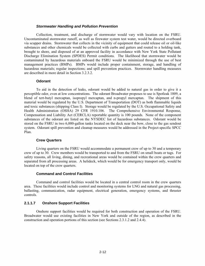
Stormwater Handling and Pollution Prevention
Collection, treatment, and discharge of stormwater would vary with location on the FSRU. Uncontaminated stormwater runoff, as well as firewater system test water, would be directed overboard via scupper drains. Stormwater that collects in the vicinity of equipment that could release oil or oil-like substances and other chemicals would be collected with curbs and gutters and routed to a holding tank, brought to shore, and disposed of at an approved facility in accordance with New York State Pollutant Discharge Elimination System (SPDES) Permit conditions. The likelihood that stormwater would be contaminated by hazardous materials onboard the FSRU would be minimized through the use of best management practices (BMPs). BMPs would include proper containment, storage, and handling of hazardous materials; regular inspections; and spill prevention practices. Stormwater handling measures are described in more detail in Section 3.2.3.2.
Odorant
To aid in the detection of leaks, odorant would be added to natural gas in order to give it a perceptible odor, even at low concentrations. The odorant Broadwater proposes to use is Spotleak 1009, a blend of tert-butyl mercaptan, isopropyl mercaptan, and n-propyl mercaptan. The shipment of this material would be regulated by the U.S. Department of Transportation (DOT) as both flammable liquids and toxic substances (shipping Class I). Storage would be regulated by the U.S. Occupational Safety and Health Administration (OSHA) 29 CFR 1910.106. The Comprehensive Environmental Response, Compensation and Liability Act (CERCLA) reportable quantity is 100 pounds. None of the component substances of the odorant are listed on the NYSDEC list of hazardous substances. Odorant would be stored on the FSRU in two 6,000-gallon tanks located on the deck near the bow, close to the gas sendout system. Odorant spill prevention and cleanup measures would be addressed in the Project-specific SPCC Plan.
Crew Quarters
Living quarters on the FSRU would accommodate a permanent crew of up to 30 and a temporary crew of up to 30. Crew members would be transported to and from the FSRU on small boats or tugs. For safety reasons, all living, dining, and recreational areas would be contained within the crew quarters and separated from all processing areas. A helideck, which would be for emergency transport only, would be located on top of the crew quarters.
Command and Control Facilities
Command and control facilities would be located in a central control room in the crew quarters area. These facilities would include control and monitoring systems for LNG and natural gas processing, ballasting, communication, radar equipment, electrical generation, emergency systems, and thruster controls.
2.1.1.7 Onshore Support Facilities
Onshore support facilities would be required for both construction and operation of the FSRU. Broadwater would use existing facilities in New York and outside of the region, as described in the construction and operation portions of this section (see Sections 2.3.1.2 and 2.4.4).
2-13
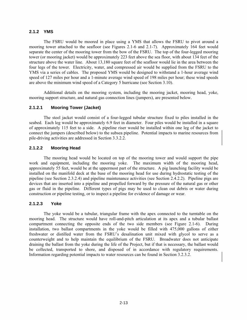
2.1.2 YMS
The FSRU would be moored in place using a YMS that allows the FSRU to pivot around a mooring tower attached to the seafloor (see Figures 2.1-6 and 2.1-7). Approximately 164 feet would separate the center of the mooring tower from the bow of the FSRU. The top of the four-legged mooring tower (or mooring jacket) would be approximately 223 feet above the sea floor, with about 134 feet of the structure above the water line. About 13,180 square feet of the seafloor would lie in the area between the four legs of the tower. Electricity, water, and compressed air would be supplied from the FSRU to the YMS via a series of cables. The proposed YMS would be designed to withstand a 1-hour average wind speed of 127 miles per hour and a 1-minute average wind speed of 198 miles per hour; these wind speeds are above the minimum wind speed of a Category 5 hurricane (see Section 3.10).
Additional details on the mooring system, including the mooring jacket, mooring head, yoke, mooring support structure, and natural gas connection lines (jumpers), are presented below.
2.1.2.1 Mooring Tower (Jacket)
The steel jacket would consist of a four-legged tubular structure fixed to piles installed in the seabed. Each leg would be approximately 6.9 feet in diameter. Four piles would be installed in a square of approximately 115 feet to a side. A pipeline riser would be installed within one leg of the jacket to connect the jumpers (described below) to the subsea pipeline. Potential impacts to marine resources from pile-driving activities are addressed in Section 3.3.2.2.
2.1.2.2 Mooring Head
The mooring head would be located on top of the mooring tower and would support the pipe work and equipment, including the mooring yoke. The maximum width of the mooring head, approximately 55 feet, would be at the uppermost part of the structure. A pig launching facility would be installed on the manifold deck at the base of the mooring head for use during hydrostatic testing of the pipeline (see Section 2.3.2.4) and pipeline maintenance activities (see Section 2.4.2.2). Pipeline pigs are devices that are inserted into a pipeline and propelled forward by the pressure of the natural gas or other gas or fluid in the pipeline. Different types of pigs may be used to clean out debris or water during construction or pipeline testing, or to inspect a pipeline for evidence of damage or wear.
2.1.2.3 Yoke
The yoke would be a tubular, triangular frame with the apex connected to the turntable on the mooring head. The structure would have roll-and-pitch articulation at its apex and a tubular ballast compartment connecting the opposite ends of the two side members (see Figure 2.1-6). During installation, two ballast compartments in the yoke would be filled with 475,000 gallons of either freshwater or distilled water from the FSRU’s desalination unit mixed with glycol to serve as a counterweight and to help maintain the equilibrium of the FSRU. Broadwater does not anticipate draining the ballast from the yoke during the life of the Project, but if that is necessary, the ballast would be collected, transported to shore, and disposed of in accordance with regulatory requirements. Information regarding potential impacts to water resources can be found in Section 3.2.3.2.

Figure 2.1-6Broadwater LNG Project
Yoke Mooring System, above Water
Note: Colors used are for clarity of illustration and are not proposed colors.
2-14
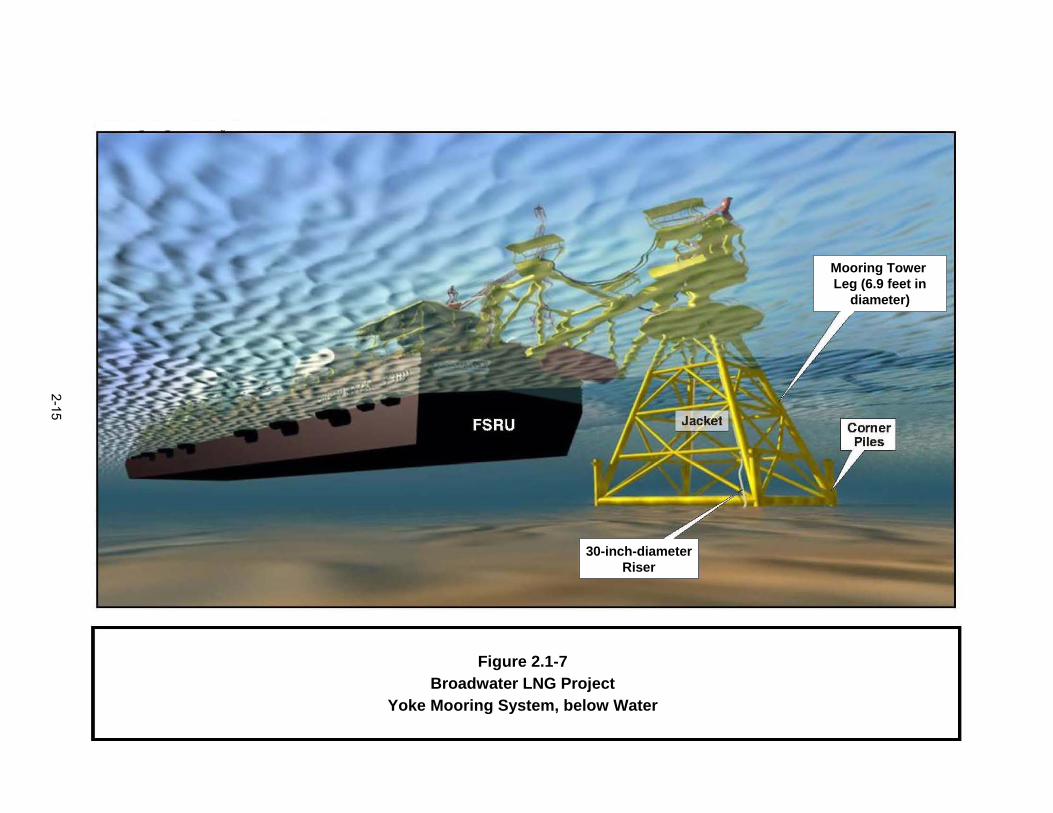
Figure 2.1-7Broadwater LNG Project
Yoke Mooring System, below Water
Mooring Tower Leg (6.9 feet in
diameter)
30-inch-diameterRiser
2-15
2-16
2.1.2.4 Mooring Support Structure
The mooring support structure would consist of a tubular steel frame mounted onto reinforced areas on the bow of the FSRU. The structure would extend over the bow of the FSRU to ensure clearance between the yoke and the FSRU during storm conditions. This structure would support the legs of the yoke and serve as a tie-in point for the flexible natural gas transfer hoses (jumpers) and communication umbilicals. The mooring support structure also would provide access between the FSRU and YMS via a stairway and ladder system.
2.1.2.5 Jumpers
The sendout gas would be transferred between the FSRU and the YMS through two 16-inch- diameter, 54.5-foot-long jumpers that would be suspended between the mooring support structure and the mooring head. The jumpers would be connected to the gas swivel on the turntable, allowing the jumpers to swivel with the weathervaning FSRU. From the gas swivel, gas is transferred to the riser that extends from the seafloor, as described below. The walls of the jumpers would be composed of 2.2-inch-thick stripwound stainless steel with rubberized textile plies (layers).
2.1.2.6 Onshore Support Facilities
Onshore support facilities would be required for both construction and operation of the YMS. Broadwater would use existing facilities in New York and outside of the region, as described in Sections 2.3.1.3 and 2.4.4.
2.1.3 Pipeline and Associated Facilities
2.1.3.1 Pipeline Specifications
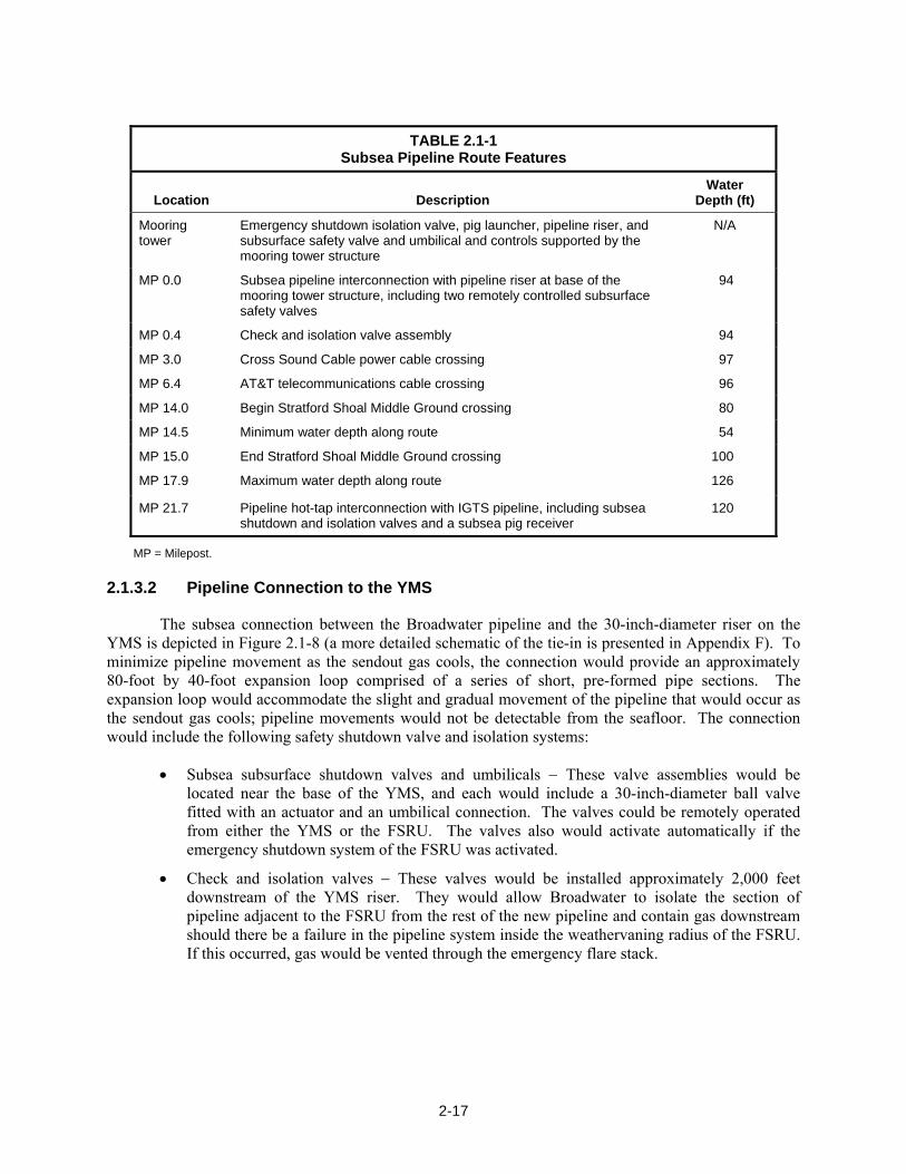
The Project would include a 30-inch-diameter subsea gas transmission pipeline extending about 21.7 miles from the FSRU to the existing IGTS pipeline (see Figure 2.1-1 and Appendix F). In accordance with 30 CFR Ch. II (7–1–04 Edition); Section 250.1003(a)(1), the pipeline would be buried to a depth of at least 3 feet below the seafloor. Design criteria for the pipeline and components described in this section would conform to the requirements of 49 CFR 192 (“Transportation of Natural and Other Gas by Pipeline: Minimum Federal Safety Standards”) and American Society of Mechanical Engineers (ASME) Bulletin 31.8 (“Gas Transmission Distribution and Piping Systems”). Key features of the subsea pipeline route are summarized in Table 2.1-1.
The wall thickness of the subsea pipeline would be designed to resist the combined loads that may be experienced during pipeline installation, testing, and normal operation. The pipeline would be designed for a maximum allowable operating pressure (MAOP) of 1,440 pounds per square inch gauge (psig) to match the MAOP of the existing IGTS pipeline. The pipeline would traverse a Class I (an offshore area) location as defined by the DOT.
2-17
TABLE 2.1-1
Subsea Pipeline Route Features
Location Description Water
Depth (ft)
Mooring tower
Emergency shutdown isolation valve, pig launcher, pipeline riser, and subsurface safety valve and umbilical and controls supported by the mooring tower structure
N/A
MP 0.0 Subsea pipeline interconnection with pipeline riser at base of the mooring tower structure, including two remotely controlled subsurface safety valves
94
MP 0.4 Check and isolation valve assembly 94
MP 3.0 Cross Sound Cable power cable crossing 97
MP 6.4 AT&T telecommunications cable crossing 96
MP 14.0 Begin Stratford Shoal Middle Ground crossing 80
MP 14.5 Minimum water depth along route 54
MP 15.0 End Stratford Shoal Middle Ground crossing 100
MP 17.9 Maximum water depth along route 126
MP 21.7 Pipeline hot-tap interconnection with IGTS pipeline, including subsea shutdown and isolation valves and a subsea pig receiver
120
MP = Milepost.
2.1.3.2 Pipeline Connection to the YMS
The subsea connection between the Broadwater pipeline and the 30-inch-diameter riser on the YMS is depicted in Figure 2.1-8 (a more detailed schematic of the tie-in is presented in Appendix F). To minimize pipeline movement as the sendout gas cools, the connection would provide an approximately 80-foot by 40-foot expansion loop comprised of a series of short, pre-formed pipe sections. The expansion loop would accommodate the slight and gradual movement of the pipeline that would occur as the sendout gas cools; pipeline movements would not be detectable from the seafloor. The connection would include the following safety shutdown valve and isolation systems:
• Subsea subsurface shutdown valves and umbilicals − These valve assemblies would be located near the base of the YMS, and each would include a 30-inch-diameter ball valve fitted with an actuator and an umbilical connection. The valves could be remotely operated from either the YMS or the FSRU. The valves also would activate automatically if the emergency shutdown system of the FSRU was activated.
• Check and isolation valves − These valves would be installed approximately 2,000 feet downstream of the YMS riser. They would allow Broadwater to isolate the section of pipeline adjacent to the FSRU from the rest of the new pipeline and contain gas downstream should there be a failure in the pipeline system inside the weathervaning radius of the FSRU. If this occurred, gas would be vented through the emergency flare stack.

Figure 2.1-8Broadwater LNG Project
Subsea Pipeline Tie-in with YMS, Conceptual Design
2-18
2-19
2.1.3.3 Pipeline Connection to the IGTS Pipeline
Broadwater would connect the new 30-inch-diameter pipeline to the existing 24-inch-diameter IGTS pipeline by installing a hot-tap connection. This procedure would allow the two pipelines to be connected without shutting down the IGTS pipeline. The connection between the Broadwater pipeline and the IGTS pipeline (depicted in Figure 2.1-9; a more detailed schematic of the tie-in is presented in Appendix F) would include a check valve, subsea shutdown and isolation systems to prevent backflow from the IGTS pipeline, and manually operated block valves that are normally open.
As depicted in Figure 2.1-9, the connection to the IGTS pipeline also would include a flange with a blind end to allow installation of a pig receiving station for pigging operations (during post-construction cleaning, caliper pigging, and periodic pipeline integrity assessments using intelligent pigs).
The Project would not require improvements to existing offshore pipelines or construction of new offshore pipelines to accommodate the output of natural gas from the FSRU, other than the proposed pipeline described above.
2.1.3.4 Corrosion Protection
The exterior of the pipeline would be coated with fusion-bonded epoxy or a similar material to reduce the likelihood of pipeline corrosion. The pipeline also would be coated with a 3-inch-thick layer of steel-reinforced concrete. The concrete coating would be applied over the fusion-bonded epoxy to decrease buoyancy and improve pipeline stability on the seafloor.
Further corrosion protection would be provided using a cathodic protection system. This system would entail running a small electrical current through the pipeline to prevent oxidation. Cathodic protection would be facilitated by sacrificial anodes incorporated into the pipeline. These anodes would have a minimum design life of 30 years. An insulating joint would be installed between the IGTS pipeline and the Broadwater pipeline to isolate the cathodic protection systems of the two pipelines.
2.1.3.5 Onshore Support Facilities
Onshore support facilities would be required for both construction and operation of the pipeline. Broadwater would use existing facilities in New York and outside of the region, as described in Sections 2.3.2.5 and 2.4.4.
The Project would not require improvements to existing onshore pipeline systems or new onshore pipelines to accommodate the natural gas output from the FSRU.
2.1.4 LNG Carriers
The Project would be designed to accommodate LNG carriers with capacities ranging from 125,000 to 250,000 m3. The fleet of LNG carriers serving the FSRU likely would be a mix of steam- and diesel-powered vessels. Nearly all of the LNG carriers currently in service are steam powered. However, approximately 15 percent of LNG carriers under construction will be diesel powered.
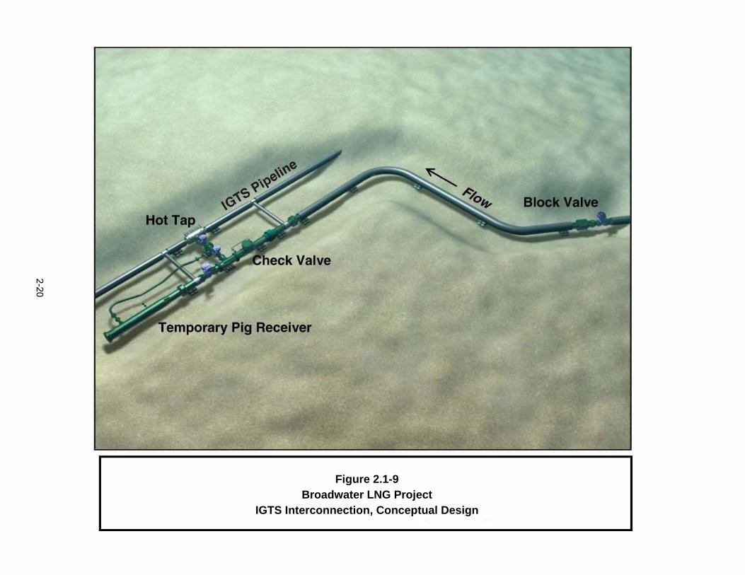
Figure 2.1-9Broadwater LNG Project
IGTS Interconnection, Conceptual Design
2-20
2-21
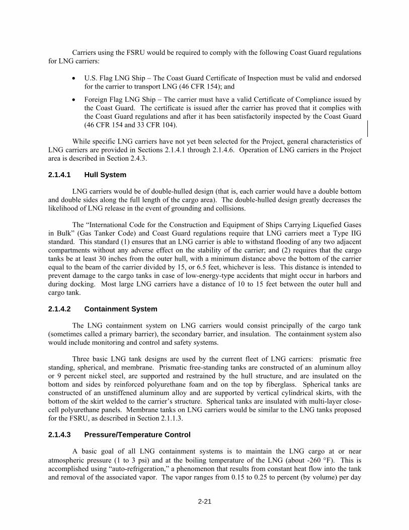
Carriers using the FSRU would be required to comply with the following Coast Guard regulations for LNG carriers:
• U.S. Flag LNG Ship – The Coast Guard Certificate of Inspection must be valid and endorsed for the carrier to transport LNG (46 CFR 154); and
• Foreign Flag LNG Ship – The carrier must have a valid Certificate of Compliance issued by the Coast Guard. The certificate is issued after the carrier has proved that it complies with the Coast Guard regulations and after it has been satisfactorily inspected by the Coast Guard (46 CFR 154 and 33 CFR 104).
While specific LNG carriers have not yet been selected for the Project, general characteristics of LNG carriers are provided in Sections 2.1.4.1 through 2.1.4.6. Operation of LNG carriers in the Project area is described in Section 2.4.3.
2.1.4.1 Hull System
LNG carriers would be of double-hulled design (that is, each carrier would have a double bottom and double sides along the full length of the cargo area). The double-hulled design greatly decreases the likelihood of LNG release in the event of grounding and collisions.
The “International Code for the Construction and Equipment of Ships Carrying Liquefied Gases in Bulk” (Gas Tanker Code) and Coast Guard regulations require that LNG carriers meet a Type IIG standard. This standard (1) ensures that an LNG carrier is able to withstand flooding of any two adjacent compartments without any adverse effect on the stability of the carrier; and (2) requires that the cargo tanks be at least 30 inches from the outer hull, with a minimum distance above the bottom of the carrier equal to the beam of the carrier divided by 15, or 6.5 feet, whichever is less. This distance is intended to prevent damage to the cargo tanks in case of low-energy-type accidents that might occur in harbors and during docking. Most large LNG carriers have a distance of 10 to 15 feet between the outer hull and cargo tank.
2.1.4.2 Containment System
The LNG containment system on LNG carriers would consist principally of the cargo tank (sometimes called a primary barrier), the secondary barrier, and insulation. The containment system also would include monitoring and control and safety systems.
Three basic LNG tank designs are used by the current fleet of LNG carriers: prismatic free standing, spherical, and membrane. Prismatic free-standing tanks are constructed of an aluminum alloy or 9 percent nickel steel, are supported and restrained by the hull structure, and are insulated on the bottom and sides by reinforced polyurethane foam and on the top by fiberglass. Spherical tanks are constructed of an unstiffened aluminum alloy and are supported by vertical cylindrical skirts, with the bottom of the skirt welded to the carrier’s structure. Spherical tanks are insulated with multi-layer close-cell polyurethane panels. Membrane tanks on LNG carriers would be similar to the LNG tanks proposed for the FSRU, as described in Section 2.1.1.3.
2.1.4.3 Pressure/Temperature Control
A basic goal of all LNG containment systems is to maintain the LNG cargo at or near atmospheric pressure (1 to 3 psi) and at the boiling temperature of the LNG (about -260 °F). This is accomplished using “auto-refrigeration,” a phenomenon that results from constant heat flow into the tank and removal of the associated vapor. The vapor ranges from 0.15 to 0.25 to percent (by volume) per day
2-22
and is used to supplement the bunker fuel in the carrier’s boilers. No mechanical means of refrigeration would be used to maintain the liquefied state of the gas; therefore, chlorofluorocarbons (CFCs) that typically present in coolants in mechanically powered refrigeration systems would not be used in this process.
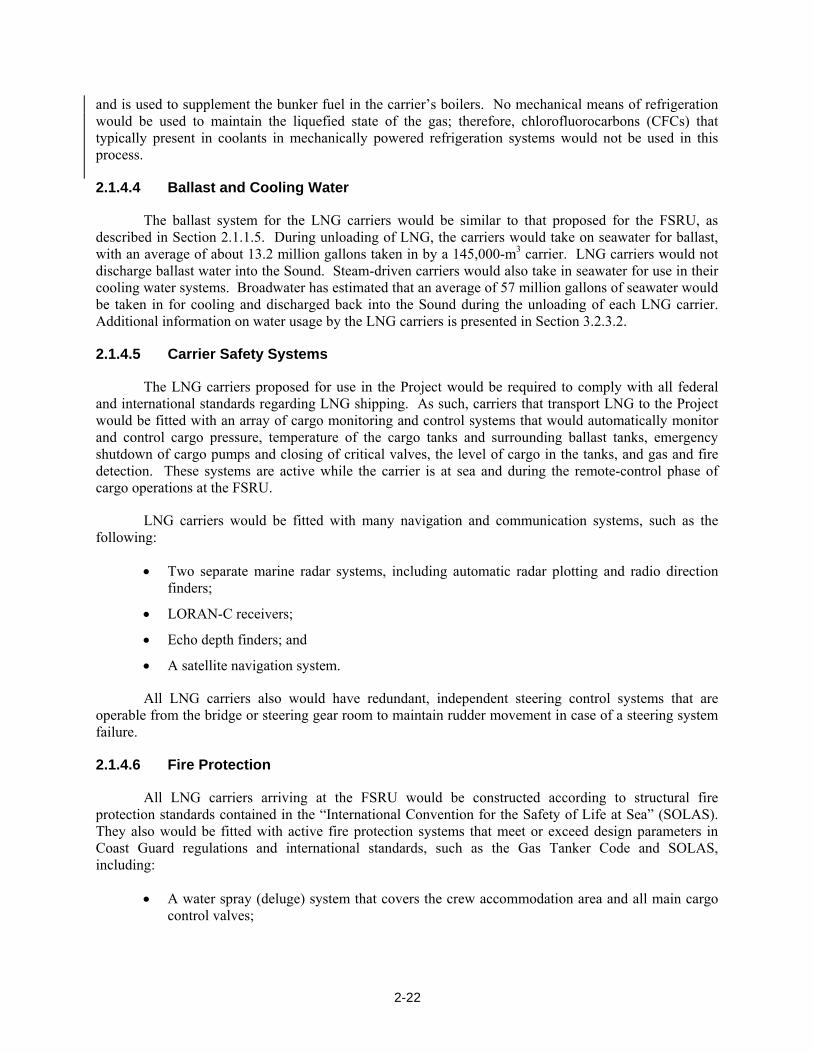
2.1.4.4 Ballast and Cooling Water
The ballast system for the LNG carriers would be similar to that proposed for the FSRU, as described in Section 2.1.1.5. During unloading of LNG, the carriers would take on seawater for ballast, with an average of about 13.2 million gallons taken in by a 145,000-m3 carrier. LNG carriers would not discharge ballast water into the Sound. Steam-driven carriers would also take in seawater for use in their cooling water systems. Broadwater has estimated that an average of 57 million gallons of seawater would be taken in for cooling and discharged back into the Sound during the unloading of each LNG carrier. Additional information on water usage by the LNG carriers is presented in Section 3.2.3.2.
2.1.4.5 Carrier Safety Systems
The LNG carriers proposed for use in the Project would be required to comply with all federal and international standards regarding LNG shipping. As such, carriers that transport LNG to the Project would be fitted with an array of cargo monitoring and control systems that would automatically monitor and control cargo pressure, temperature of the cargo tanks and surrounding ballast tanks, emergency shutdown of cargo pumps and closing of critical valves, the level of cargo in the tanks, and gas and fire detection. These systems are active while the carrier is at sea and during the remote-control phase of cargo operations at the FSRU.
LNG carriers would be fitted with many navigation and communication systems, such as the following:
• Two separate marine radar systems, including automatic radar plotting and radio direction finders;
• LORAN-C receivers;
• Echo depth finders; and
• A satellite navigation system.
All LNG carriers also would have redundant, independent steering control systems that are operable from the bridge or steering gear room to maintain rudder movement in case of a steering system failure.
2.1.4.6 Fire Protection
All LNG carriers arriving at the FSRU would be constructed according to structural fire protection standards contained in the “International Convention for the Safety of Life at Sea” (SOLAS). They also would be fitted with active fire protection systems that meet or exceed design parameters in Coast Guard regulations and international standards, such as the Gas Tanker Code and SOLAS, including:
• A water spray (deluge) system that covers the crew accommodation area and all main cargo control valves;

2-23
• A traditional firewater system that provides water to fire monitors on deck and to fire stations found throughout the carrier;
• A dry powder extinguishing system for LNG fires. The dry powder system would be used to extinguish LNG fires and prevent ignition of LNG leaks. Automatic dry powder extinguisher system would be integrated into the exposed deck of the cargo (LNG) area, loading arms and cargo tank domes, and in the LNG processing area; and
• A carbon dioxide system for protecting the machinery, ballast pumps, emergency generators, and cargo compressors.
Further details regarding fire protection systems are provided in Section 3.10.
2.2 LAND AND SURFACE REQUIREMENTS
Table 2.2-1 summarizes the land requirements for the facilities associated with the Broadwater Project. Additional information on land requirements is presented in Section 3.5.
TABLE 2.2-1 Summary of Land Requirements
Project Component Land Affected during Construction (acres)
Land Affected during Operation (acres)
Proposed Fixed Safety and Security Zone (around the YMS
and FSRU)a
FSRU N/Ab N/A Included in the safety and security zone around the
YMS
YMS -c 0.3c 950.3 acres
Pipeline 197.3d 78.9 e --
Anchor footprint 16.0 N/A N/A
Anchor cable sweep f 2,020 N/A N/A
Tie-ins and utility crossings 1.9 N/A N/A
Pipe storage yard/onshore support facilities g N/A N/A N/A
Total 2,235.5 79.2 950.3
a The radius of the proposed safety and security zone would be measured from the center of the mooring tower of the YMS. b N/A = Not applicable. The FSRU would be constructed at an existing shipyard and towed to the mooring tower. c Construction impacts would include a 650-foot square construction vessel anchoring area surrounding the tower; anchor cable
impacts would not occur if mid-line buoys were deployed on all anchor lines. (We have included a recommendation in Section 3.1.2.2 that Broadwater incorporate mid-line buoys on all anchor lines or use dynamically positioned pipelay and burial vessels). This entire area would be within the construction area listed for the pipeline. The area of land affected during operation is the seafloor footprint of the mooring tower.
d Acreage is based on a 75-foot-wide pipeline construction impact area that includes a 25-foot-wide trench and adjacent spoil piles. We do not anticipate the need for a temporary safety and security zone around the pipeline during construction, but a final determination would be made by the Coast Guard.
e Operation acreage is based on a 30-foot-wide pipeline permanent right-of-way (ROW). f Values provided are Broadwater estimates and assume that all anchor cable sweep would occur outside the 75-foot-wide
pipeline construction impact area. The acreage would decrease substantially if our recommendation for mid-line buoys on all anchor cables is incorporated into the Project (see Section 3.1.2.2).
g The pipe storage yard and other onshore support facilities would use existing facilities and would not require additional land.
2-24
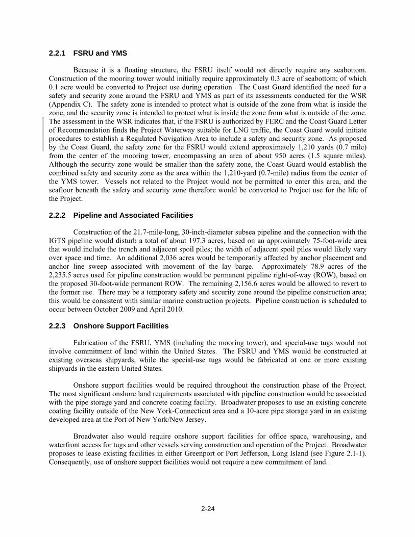
2.2.1 FSRU and YMS
Because it is a floating structure, the FSRU itself would not directly require any seabottom. Construction of the mooring tower would initially require approximately 0.3 acre of seabottom; of which 0.1 acre would be converted to Project use during operation. The Coast Guard identified the need for a safety and security zone around the FSRU and YMS as part of its assessments conducted for the WSR (Appendix C). The safety zone is intended to protect what is outside of the zone from what is inside the zone, and the security zone is intended to protect what is inside the zone from what is outside of the zone. The assessment in the WSR indicates that, if the FSRU is authorized by FERC and the Coast Guard Letter of Recommendation finds the Project Waterway suitable for LNG traffic, the Coast Guard would initiate procedures to establish a Regulated Navigation Area to include a safety and security zone. As proposed by the Coast Guard, the safety zone for the FSRU would extend approximately 1,210 yards (0.7 mile) from the center of the mooring tower, encompassing an area of about 950 acres (1.5 square miles). Although the security zone would be smaller than the safety zone, the Coast Guard would establish the combined safety and security zone as the area within the 1,210-yard (0.7-mile) radius from the center of the YMS tower. Vessels not related to the Project would not be permitted to enter this area, and the seafloor beneath the safety and security zone therefore would be converted to Project use for the life of the Project.
2.2.2 Pipeline and Associated Facilities
Construction of the 21.7-mile-long, 30-inch-diameter subsea pipeline and the connection with the IGTS pipeline would disturb a total of about 197.3 acres, based on an approximately 75-foot-wide area that would include the trench and adjacent spoil piles; the width of adjacent spoil piles would likely vary over space and time. An additional 2,036 acres would be temporarily affected by anchor placement and anchor line sweep associated with movement of the lay barge. Approximately 78.9 acres of the 2,235.5 acres used for pipeline construction would be permanent pipeline right-of-way (ROW), based on the proposed 30-foot-wide permanent ROW. The remaining 2,156.6 acres would be allowed to revert to the former use. There may be a temporary safety and security zone around the pipeline construction area; this would be consistent with similar marine construction projects. Pipeline construction is scheduled to occur between October 2009 and April 2010.
2.2.3 Onshore Support Facilities
Fabrication of the FSRU, YMS (including the mooring tower), and special-use tugs would not involve commitment of land within the United States. The FSRU and YMS would be constructed at existing overseas shipyards, while the special-use tugs would be fabricated at one or more existing shipyards in the eastern United States.
Onshore support facilities would be required throughout the construction phase of the Project. The most significant onshore land requirements associated with pipeline construction would be associated with the pipe storage yard and concrete coating facility. Broadwater proposes to use an existing concrete coating facility outside of the New York-Connecticut area and a 10-acre pipe storage yard in an existing developed area at the Port of New York/New Jersey.
Broadwater also would require onshore support facilities for office space, warehousing, and waterfront access for tugs and other vessels serving construction and operation of the Project. Broadwater proposes to lease existing facilities in either Greenport or Port Jefferson, Long Island (see Figure 2.1-1). Consequently, use of onshore support facilities would not require a new commitment of land.

2-25
2.3 CONSTRUCTION PROCEDURES
The proposed LNG terminal and natural gas pipeline would be designed and constructed in accordance with federal safety standards that are intended to ensure adequate protection for the public and to prevent LNG and natural gas pipeline accidents or failures. Broadwater also would construct the FSRU and proposed pipeline in accordance with FERC’s Wetland and Waterbody Construction and Mitigation Procedures (Procedures), as they apply to offshore pipeline construction (see Section 3.2.2). During final design, Broadwater would prepare an Erosion and Sedimentation Control Plan specific to the Project that would be used during construction of the pipeline.
2.3.1 LNG Terminal
2.3.1.1 Design Requirements
As described in Section 2.1.1.1, the FSRU would be designed and constructed in accordance with classification society rules that govern the following:
• Classification of a floating offshore installation at a fixed location;
• Construction and classification of ships for the carriage of liquefied gases in bulk; and
• Rules and regulations for the classification of ships.
Although onshore LNG terminals are designed and constructed in accordance with DOT’s “Liquefied Natural Gas Facilities: Federal Safety Standards” (49 CFR 193) and the National Fire Protection Association (NFPA) “Standards for the Production, Storage, and Handling of LNG” (NFPA 59A), these standards do not directly apply to an FSRU, which is a floating structure. Those portions of 49 CFR 193 that apply to the design, construction, and operation of the FSRU would be evaluated by the classification society in its certification review of the proposed Project. Where appropriate, given the novel configuration, Broadwater would be required to prepare and submit alternative procedures, methods, and equipment to the Captain of the Port in accordance with 33 CFR 127.017. Engineering design review is being conducted by the Coast Guard and FERC. Additional information on key aspects of the design is included in Section 3.10.
2.3.1.2 FSRU Fabrication and Installation
The FSRU would be constructed at an overseas shipyard and would be towed to Long Island Sound for installation. As part of the classification society’s review of the proposed Project, classification society surveyors in coordination with the Coast Guard would observe construction of the FSRU in the shipyard and inspect production of key components of the FSRU, including hull materials, generators, and other heavy equipment, to verify that the FSRU is constructed in accordance with classification society rules. In accordance with International Maritime Organization requirements (particularly the International Convention for the Control and Management of Ships’ Ballast Water and Sediments), the FSRU would exchange ballast prior to entering Long Island Sound. The ballast exchange would take place at least 200 nautical miles from the nearest land, in waters with a depth of at least 200 meters, and would require the exchange of 95 percent of the ballast water. This would avoid introducing foreign species that may be present in the FSRU ballast water into Long Island Sound. The International Maritime Organization may institute more stringent requirements for the control of invasive organisms in ballast water as part of their International Convention for the Control and Management of Ships’ Ballast Water and Sediments. A more detailed description of these pending measures is provided in Section 3.2.3.2.
2-26
The FSRU would be towed into Block Island Sound and through the Race to enter Long Island Sound in accordance with Coast Guard regulations.
2.3.1.3 YMS Fabrication and Delivery
Fabrication
The YMS also would be constructed at an overseas shipyard and towed to Long Island Sound for installation. The mooring tower would consist of three separately fabricated segments (jacket, topsides, and mooring yoke), each of which would be sequentially installed at the proposed location of the YMS prior to FSRU and sendout pipeline hookup.
Classification society surveyors would observe construction of the YMS in the shipyard to verify that it is constructed in accordance with classification society rules.
Installation
To maintain the stability of the mooring tower during lowering to the sea floor, a wooden frame (termed a “mud mat”) constructed of untreated lumber would be installed between the legs of the tower and would remain in place for the life of the Project or until it degrades. During installation, the mud mat or jacket would be pressed into the seafloor within the footprint of the proposed YMS; no excavation would be necessary. After setting the jacket in place, piles would be driven through pile guides in each leg of the jacket to a depth of approximately 230 feet below the seafloor, with the piles installed in a square of approximately 115 feet to a side. The actual depth that the piles would need to be driven would be determined based on a subsea geotechnical investigation to be completed prior to final design. Based on preliminary geotechnical design information, Broadwater anticipates using a hydraulic hammer to drive the piles. The legs of the tower would be installed one by one, and installation would require 1 week for each leg. During installation, pile-driving would be limited to 12 hours per day and would not occur at night. The space between the piling and the jacket leg would be filled with grout that would be injected from the surface using flexible hoses and either a diver or a remotely operated vehicle. During installation, the support barge would maintain position by anchoring in a square anchor pattern of approximately 650 feet per side. The support barge would not move during installation of the mooring tower, and the barge’s anchors would impact less than 0.5 acre of seabottom. Section 3.3.2.2 includes a recommendation that, prior to construction, Broadwater coordinate with NMFS to ensure that the potential impacts to marine resources due to installation of the pilings would be minimized.
YMS installation would be completed by attaching the topsides, connecting the mooring yoke to the jacket, installing the riser, and connecting the pipeline and the FSRU to the YMS.
The following types of vessels would be required for installation of the YMS:
• Crane barge;
• Support barge;
• Tugs;
• Dive support vessel; and
• Personnel carrier and utility launches.
2-27
A total of 132 workers would be employed during installation of the YMS, with an estimated peak workforce of 64 over a 14-day period. The majority of workers would be housed on the construction barge, although some short-term workers may require onshore housing.
2.3.2 Pipeline and Associated Facilities
The proposed pipeline facilities would be designed and constructed in accordance with 49 CFR 192. Among other design standards, these regulations specify pipeline material selection; minimum design requirements; protection from internal, external, and atmospheric corrosion; and qualification procedures for welders and operations personnel. In addition, Broadwater would comply with the requirements in 18 CFR 380.15 (“Siting and Maintenance Requirements”) and other applicable federal and state regulations.
Construction of the majority of the proposed pipeline would be accomplished using conventional underwater pipe lay techniques (Section 2.3.2.1). Special pipeline construction techniques would be used when installing the pipeline across existing cables and at the interconnections with the YMS riser and the existing IGTS pipeline (Section 2.3.2.2).
2.3.2.1 Typical Construction Techniques
The pipe segments would be coated with concrete at an existing facility located outside of the New York-Connecticut area. From there, approximately 3,000 40-foot-long segments of concrete-coated pipe would be shipped by rail to a pipe storage yard within a developed area of the Port of New York/New Jersey. The concrete-coated pipe would be transferred to barges, towed to the work site by up to six tugs, and transferred to a lay barge. The lay barge would serve as the main work area for inspection and welding of the pipe joints (40-foot sections of pipe) and as the platform from which the welded pipe segments would be laid onto the seafloor. The lay barge also would have accommodations for the construction crews.
Once the pipeline is laid on the seafloor, it would be installed below the seabed along its entire length. Broadwater proposes to install the pipeline using a post-lay plow, which would remove soil from the underneath and sides of the pipeline after the pipe has been placed on the seafloor.
The peak workforce associated with pipeline installation is estimated at 400 personnel, with approximately 350 workers and 20 to 30 inspectors and managers occupying the lay barge and support vessels, and 20 workers supporting onshore operations over a 95-day construction period.
Pipe Lay
The pipe would be laid on the seafloor from a pipeline lay barge, using a method known as S-Lay (see Figure 2.3-1). The pipe lay barge would be approximately 400 feet long and 20 feet wide with a draft of 20 feet. Broadwater has proposed to use an eight-point mooring system with mid-line buoys on four of the anchors to maintain position of the barge. The anchors would be repositioned periodically, and the barge would move forward in 40-foot increments along the proposed pipeline centerline by adjusting tension on the anchor lines. As shown in Figure 2.3-1, anchoring would take place within a 4,000-foot-wide area centered on the pipeline alignment. Anchor-handling tugs would recover and relocate anchors, and would adjust anchor lines from the lay barge and other vessels during the pipe lay and lowering operations. If an anchored lay barge is used, Broadwater would develop anchor and cable management requirements during the detailed design stage. As noted in Section 3.1.2.2, we have

Figure 2.3-1Broadwater LNG Project
Typical Pipeline Lay Barge Spread
Note: Mid-line anchor buoys not shown.
2-28
2-29
recommended that Broadwater use mid-line buoys on all anchor cables or use a dynamically positioned barge that does not use anchor lines (see Section 4.6).
As the lay barge moves forward, pipe joints would be positioned and welded together in an assembly line. The welded pipe joints would be laid onto the seafloor from a “stinger” at the aft end of the lay barge. Welding of additional joints to the end of the pipeline and forward motion of the lay barge would occur in a continuous fashion.
Pipeline Installation
Pipeline installation would be accomplished primarily by the post-lay plowing method. A post-lay plow, illustrated in Figure 2.3-2, would be positioned around the installed pipeline on rollers and would be pulled forward by a “pull barge” (either the lay barge or a dynamically positioned barge of similar dimensions). As the plow advances, it would excavate a trench below the pipeline and the pipeline would lower into the trench in the seafloor as the plow is pulled ahead. Schematics showing typical plowed trench configurations are presented in Appendix F. Sediment displaced by the plow would be pushed to the side of the resultant trench. The width of these adjacent spoil piles would be expected to average 75 feet; however, they may vary in width over space and time based on the composition of the spoil material and current and wave activity in a given area. Broadwater anticipates that two passes of the post-lay plow would be required to excavate a trench 6 feet deep. The trench would be excavated by the barge/vessel, and the depth of the trench would be verified through periodic diver checks.
The width of seabed disturbance at the top of the trench would be about 25 feet (not including spoil piles adjacent to the trench), resulting in a total area of disturbance of about 67 acres (not including spoil piles adjacent to the trench). Broadwater has proposed to allow the trench to fill in by natural processes and estimated that the trench would be approximately 1 foot below the existing contour within approximately 36 months of completion of construction. As described below, in areas where specialized construction techniques are used, Broadwater would mechanically backfill the excavations. Section 3.1.2.2 includes a recommendation that Broadwater actively bury the pipeline after it is installed in the trench.
2.3.2.2 Special Construction Techniques
Special construction techniques would be required where the pipeline route crosses cables, for the tie-ins with the riser pipeline of the YMS and with the IGST pipeline, and across Stratford Shoal. These techniques are described below.
Cable Crossings
Installation of the proposed pipeline would require crossing two utility cables: the AT&T telecommunications cable, buried 6 to 7 feet below the seafloor at Milepost (MP) 6.4; and the Cross Sound Cable, an electrical power transmission cable buried 6 to 7 feet below the seafloor at MP 3.0. In accordance with 49 CFR 192, crossing bridges would be installed between the proposed pipeline and the existing cables, providing a minimum of 12 inches of separation between cable and pipeline. The following construction methods would be used at each of the cable crossings to ensure that this separation is provided:
• Each cable would be located using high-resolution sonar, and its location would be marked by divers.
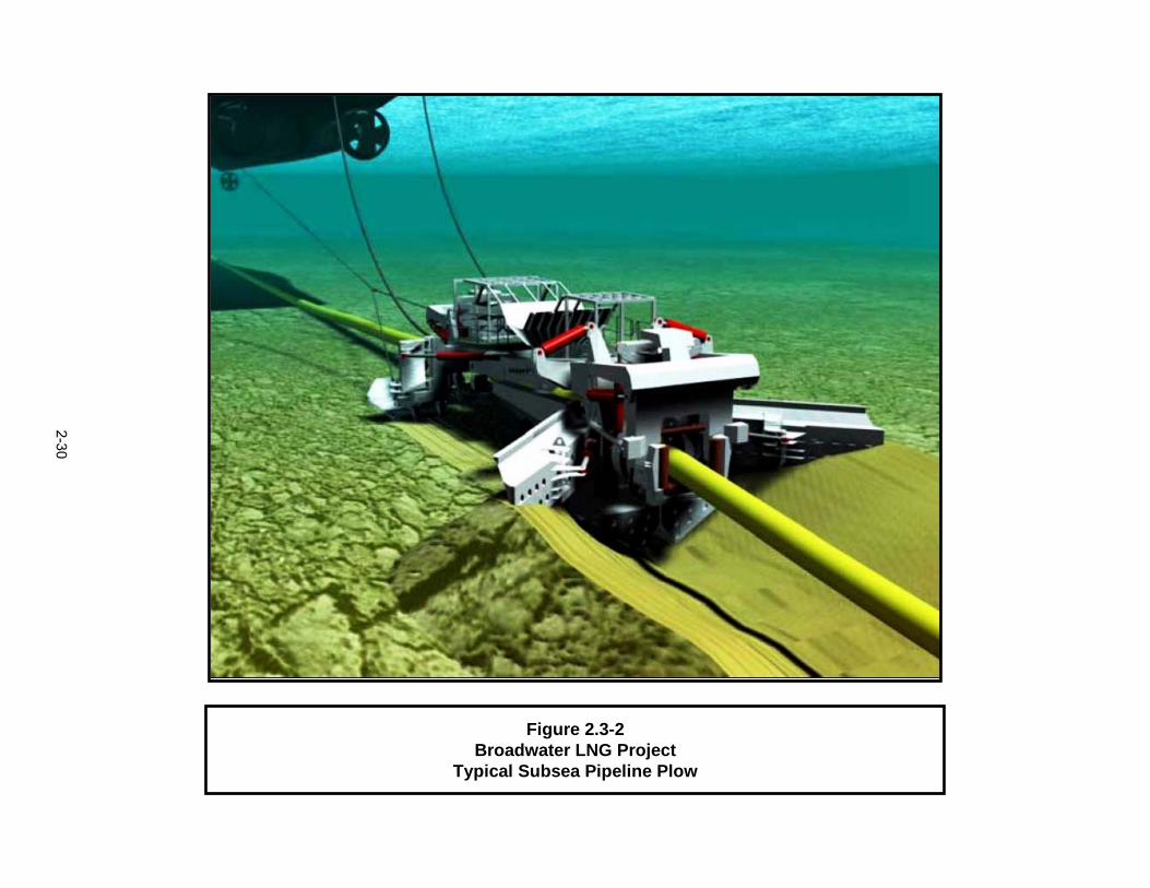
Figure 2.3-2Broadwater LNG Project
Typical Subsea Pipeline Plow
2-30
2-31
• Prior to laying the pipeline on the bottom, divers would use hand-operated dredging equipment to excavate the area over and adjacent to the cable.
• Concrete mats would be placed over the cable and adjacent and parallel to it for the pipeline.
• The pipeline would be laid on top of the mats and essentially would bridge over the cable.
• Post-lay plowing would stop approximately 160 feet on each side of the cable.
A schematic drawing of the construction procedures is presented in Appendix F. Broadwater would develop detailed installation plans for the cable crossings and submit these to the cable owners for review and approval prior to commencing pipeline construction in those areas.
Subsea Tie-in with YMS
After installation of the subsea pipeline and the YMS, Broadwater would connect the subsea pipeline to a 30-inch-diameter pipeline riser that would be present within the mooring tower. The riser would be pre-installed and hydrostatically tested during fabrication of the YMS. Connection of the subsea pipeline to the riser would involve installation of an expansion loop (described in Section 2.1.3.2 and illustrated in Figure 2.1-8 and in Appendix F). Divers supported by a dive vessel would connect the expansion loop to a pre-installed flange on the riser and to the subsea pipeline. The riser would be flooded with test water prior to connection; and divers would perform safety checks to ensure that pressure does not differ among the riser, the expansion loop, and the pipeline.
Divers also would use submersible pumps to excavate sediments to a depth of approximately 8 feet in the area prior to installation of the expansion loop and connection of the subsea pipeline. Following installation, the excavated area would either be backfilled with native material or covered with a protective metal cage equipped with an access panel.
Subsea Tie-in with IGTS Pipeline
After the subsea pipeline is installed, it would be connected to the existing IGTS pipeline using a mechanical hot-tap connection, as described in Section 2.1.3.3 and illustrated in Figure 2.1-9 and in Appendix F. The hot-tap connection first would be attached to the IGTS pipeline and then would be connected to the Broadwater subsea pipeline.
Because of the estimated size and weight of structures and equipment associated with the hot-tap connection, they would be installed by the lay barge (using its heavy-lift derrick) rather than by a dive support vessel. Lay barge anchors would be placed a minimum distance of 1,500 feet on the west side and 500 feet on the east side of the IGTS pipeline. Divers using submersible pumps would excavate the area of the hot-tap connection to a depth of approximately 8 feet below the seafloor.
After removing concrete and other protective materials from the IGTS pipeline, the hot-tap clamp would be lowered and attached. All fittings would be tested to ensure proper seals and that the integrity of the IGTS pipeline is maintained. The hot-tap assembly would be connected to a series of shutdown valves that would be connected to the Broadwater pipeline. In addition, a blind flange would be connected that would provide a connection to a temporary pig receiver trap. The hot-tap assembly and valves would be covered with sandbags or concrete mats after installation to provide protection and allow access during hydrostatic testing and other maintenance activities.
2-32
Installation at Stratford Shoal
Broadwater’s geotechnical investigations indicated that pebbles, cobbles, and small boulders along the proposed pipeline route in the vicinity of Stratford Shoal Middle Ground (MP 13 to 14) are within the depth that would need to be excavated for pipeline installation. Post-lay plowing in this area would require greater pulling force and may introduce the potential for the excavated boulders to damage the pipeline. Broadwater would conduct additional investigations using a scaled-down subsea plow to determine whether or not geotechnical conditions across Stratford Shoal would allow pipeline installation using the post-lay plowing method. If a post-lay plow is used, the plowing rate would be reduced between MP 14 and 15 to permit closer monitoring by divers of the trenching progress and immediate identification and removal of any boulders that may become lodged between the plow and the pipeline. If the additional investigations indicate that the post-lay plowing method would not be appropriate, Broadwater would develop an alternative installation method for this portion of the route. These alternatives could include use of a barge-mounted excavator or laying the pipeline on the seafloor and covering it with articulated concrete mats (see Section 3.1.2.2).
2.3.2.3 Pipeline Construction Support Vessels
Installation of the pipeline would require the use of several types of support vessels, as described below.
Dive Support Vessel
Dive support vessels would be used where diving operations and subsea construction are required in water of shallow to moderate depth. A typical dive support vessel would have a suitable deck for diving and construction equipment, and may include facilities for pipe welding and other construction activities. The vessel also would have living and dining accommodations for crew and construction staff.
Mooring for a typical dive support vessel would consist of three or four anchors placed at pre-selected locations either by the dive support vessel or by a support tug. Dynamically positioned dive support vessels also could be used. These vessels would be similar to the anchored dive support vessels but would support saturation diving and would generally be better suited for operation in areas where water depth exceeds 40 feet.
Anchor-Handling Tugs
Anchor-handling tugs would be responsible for placement, retrieval, and repositioning of anchors and anchor lines during pipe lay and pipe installation activities. These tugs, which are specifically designed and constructed for this purpose, are generally more powerful and maneuverable and have greater lifting capacity than standard tugs. Operators of the lay barge may supply their own anchor-handling tugs and crews.
Survey Vessel
A survey vessel would be used to verify bottom features in advance of and concurrent with pipe lay activities. The vessel would likely be approximately 125 feet long and would be equipped with a differential global positioning system, an echo sounder, side-scan sonar, magnetometer, and pipeline and cable locating equipment.
2-33
Pipe Supply Barges and Tugs
Barges would be used to supply pipe segments to the lay barge during pipe lay operations. These supply barges typically would be from 100 to 300 feet long and would be towed by tugs. The barges, assisted by a minimum of six tugs, would transit from the Port of New York/New Jersey on the west through the western portion of the Sound to the pipeline installation area.
Hydrostatic Testing and Dewatering Support Vessels
To support hydrostatic testing and dewatering of the subsea pipeline, one or more platform support vessels would be required. These vessels would be equipped with cranes and other heavy equipment, including air compressors, pumps, and other equipment needed for pigging, drying, and dewatering. The hydrostatic testing and dewatering support vessels could maintain their position by use of anchors or by dynamic positioning.
Security and Escort Boats
Security and escort boats, which would be similar to harbor pilot boats, would be used to keep other vessels aware of the movements of the lay barge and other construction vessels. If a vessel not related to the Project entered the construction area, the security and escort boats would approach the vessel and ensure its safe passage out of the area.
Personnel Carriers and Utility Launches
Small general-purpose vessels would be used as personnel carriers and utility launches to service the construction vessels as appropriate. These vessels would be chartered locally within the Project area.
2.3.2.4 Hydrostatic Testing
After the subsea pipeline is installed, but prior to installation of the YMS and final connection to the IGTS pipeline, the pipeline and all of the associated connection piping would be hydrostatically tested in accordance with 49 CFR 192. Hydrostatic testing activities, including attachment of temporary pig launching and receiving traps, would be conducted from support vessels, as described in Section 2.3.2.3.
Filtered seawater treated with a biocide to prevent the growth of algae would be used to propel pigs through the pipeline. Seawater would be pumped from a depth of 20 to 40 feet below the sea surface through a 74-micron mesh sieve and into a container, where biocide would be added before introduction into the pipeline. Approximately 3.9 million gallons of water would be required to fill the pipeline.
A temporary pig launcher would be installed at the eastern end of the pipeline, and a temporary pig receiver would be installed at the western end of the pipeline. A cleaning pig would be sent through the pipeline to remove dirt or construction debris. The temporary pig receiver would be removed, lifted to the dive support vessel, emptied, and relowered and reconnected. A pollution dome would be used during recovery operations to ensure that hydrocarbons and other foreign materials do not enter the water column. This device is an umbrella-shaped structure with a hose at the center that would be placed over the area to be disconnected or connected. Hydrocarbons and other materials lighter than water would be trapped within the dome and transferred through the hose to a tank on the dive support vessel.
After cleaning, the pipeline would be filled with the filtered and treated seawater, and the pig launcher and receiver would be replaced with pressure-testing heads. The pipeline would be monitored to confirm that pressure is not lost during the minimum 8 hours of test, as prescribed by 49 CFR 192. After
2-34
testing is complete, the pressure would be bled off and valves at both ends of the pipeline would be closed.
After installation of the YMS and completion of the hot-tap connection to the IGTS pipeline, test water would be purged from the pipeline by launching a dewatering pig from the pig launcher on the YMS. Water displaced by the dewatering pig would be routed by flexible hoses to a tank on the support barge or on a separate storage barge. In the holding tanks, the biocide-treated fill medium water would be neutralized, using hydrogen peroxide at a concentration of 150 to 750 ppm. After the biocide is neutralized, the water would be discharged back to the Sound. The pipeline then would be dried and purged using nitrogen gas and filled with natural gas, with continuous analysis to ensure that a correct dosage is being injected. The injection operation would be computer controlled and monitored. The dosage rate would depend on the remaining active constituent (see Section 3.2.3). The hydrostatic test water would be discharged back to Long Island Sound only after the biocide has been effectively neutralized. After the majority of the test water had been discharged and accounted for, the line would be dried and purged using nitrogen. After that, the pipeline could be put into service.
2.4 OPERATION AND MAINTENANCE
Operation of the proposed Project would involve importation and transfer of LNG to the FSRU from LNG carriers, regasification of LNG on the FSRU, and transfer of regasified LNG (natural gas) into the 21.7-mile subsea pipeline and ultimately into the existing IGTS pipeline system. Figure 2.1-5 presents a schematic diagram of the overall process. The key components of operation for each of these activities are described in the following sections. The proposed Project would be operated and maintained in accordance with 33 CFR 127, 33 CFR 154, 33 CFR Subchapter NN, and 49 CFR 192.
2.4.1 LNG Terminal
Imported LNG would be obtained from liquefaction plants throughout the world and would be delivered by LNG carriers. Upon arrival at the FSRU, each LNG carrier would dock at the berthing area along the starboard side of the FSRU, attach to the FSRU’s unloading arms, and transfer LNG to the FSRU’s storage tanks. LNG would be transferred at a maximum rate of 5,000 m3 per hour per arm. One of the transfer arms would return vapor to the LNG carrier in order to maintain a gas atmosphere and prevent air intrusion. Side-shell water curtains would operate on both the FSRU and the LNG carrier during all LNG transfer operations.
From the storage tanks on the FSRU, LNG would be transferred by in-tank submersible pumps to a series of vaporizers, and then through the sendout lines and riser pipeline and into the subsea pipeline.
Eight closed-loop STVs would be used to convert the LNG to natural gas. After leaving the STVs, the vaporized gas would be heated to up to 144ºF by superheaters to meet the requirements of the IGTS pipeline system. Process heaters would consume natural gas at a rate of 6 million cubic feet per day when operating at 100 percent load. The heated gas would be transferred through a metering system on the FSRU, treated with nitrogen and odorant as needed to meet pipeline specifications and delivery gas requirements, and transmitted to the subsea pipeline.
During normal operations, some LNG vapor would accumulate within the LNG storage tanks as a result of changes in heat and pressure and through displacement from the carriers as LNG is loaded into the FSRU. The vapor-handling system would collect boil-off gas and direct it back to the LNG carrier, to the process heaters for use as fuel, or to the recondenser that would re-liquefy the vapor back to LNG and route it to the storage tanks on the FSRU.

2-35
As the LNG is unloaded, ballast water would be taken on to compensate for the weight of the unloaded cargo (see Section 3.2.3 for additional information). After completion of cargo transfer, the unloading arms and umbilicals would be detached, and the carrier would depart with tug assistance. The entire unloading process from ship arrival to departure would take approximately 25 hours.
In the WSR (Appendix C), the Coast Guard identified the use of tug assistance during portions of the LNG vessel transit to the FSRU as a recommended safety measure. If the Letter of Recommendation finds the Project Waterway suitable for LNG marine traffic with implementation of the mitigation measures proposed by the Coast Guard, one of the mitigation measures would require Broadwater to conduct an assessment of and prepare a report on the number of tug boats considered sufficient for this purpose. The Coast Guard would review the Broadwater tug support plan and would not approve any LNG carrier operations until a suitable plan is submitted and implemented.
Tugs would be constructed at an existing United States shipyard and would be based at a waterfront facility in either Greenport or Port Jefferson, New York (see Figure 2.1-1). The tugs would be equipped with fire-fighting equipment and would provide support in the event of a fire on the FSRU or an LNG carrier, or a pool fire on the water. Three or four tugs would assist with LNG carrier berthing, with the number of tugs determined by the size of the carrier, the season of the year, and weather conditions (see Appendix C, Section 4.6.1.3). The Coast Guard’s findings in the WSR (Appendix C) indicate that two tugs may need to remain within the safety and security zone during LNG unloading to assist if the FSRU mooring system fails, or if otherwise needed. The details of this requirement would be finalized in a Regulated Navigation Area. Additional information regarding the use of tugs is provided in Section 4.6.1.3 of the WSR.
After completion of construction and prior to commissioning of the FSRU, a ship classification society would review the results of construction surveys and Broadwater’s proposed operation procedures before issuing a class certification for the FSRU. Currently, ABS is the proposed ship classification society that would conduct the review. Further, while in service, the FSRU would be subject to a regular schedule of operations surveys that would be carried out onboard the FSRU to verify that the FSRU continues to meet class requirements. In addition, the FSRU would be subject to joint inspection by the Coast Guard and FERC. Once the LNG terminal is operational, The EPAct of 2005 authorizes the state commission to conduct safety inspections and provide notice of any violations for appropriate action by FERC. The mechanics of coordination between FERC and the State would be worked out closer to the date of construction. We anticipate that state safety inspections would be performed concurrent with FERC inspections. However, other approaches would be considered.
Approximately 60 full-time workers would be employed to operate the Project. About 50 of these workers would operate the FSRU, working in shifts of 25 on and 25 off. The remaining 10 workers would conduct a variety of support activities. All operations and maintenance personnel at the FSRU would be trained to properly and safely perform their assignments. The terminal operators would be trained in LNG safety, cryogenic operations, and proper operation of respective terminal control equipment. The operators would meet the training requirements of the applicable regulatory entities.
During final design, Broadwater would develop maintenance plans for the FSRU and YMS. Although the details are not available, Broadwater anticipates that the maintenance program would include visual inspections, operational checks and tests, routine onboard mechanical and electrical maintenance activities, lubrication schedules and regular steelwork examinations, and surveys above and below the water line. Underwater maintenance may include surface cleaning of the hull and other parts to remove localized accumulations of slime and weeds. The cleaning would be accomplished by divers and would consist of light brushings conducted no more than once per year. If mechanical repairs to underwater parts of the FSRU or YMS are necessary, the area to be repaired would be segregated from
2-36
seawater by a cofferdam installed by divers. Broadwater does not plan to recoat underwater portions of either the FSRU or YMS as a part of its maintenance program. No maintenance dredging would be required.
Broadwater would maintain a full-time maintenance staff to perform routine maintenance and minor overhauls at the FSRU. Major overhauls and major maintenance activities would be handled by trained and qualified contract personnel, and would be scheduled using a computerized database system. Unscheduled maintenance activities would be identified and tracked by the same database. The maintenance database would address all facility components, including process equipment, safety and environmental equipment, and instrumentation. Broadwater would train all facility operations and maintenance personnel on the use of the database.
We received a comment on the draft EIS expressing concern about the possibility of excessive helicopter flights and requesting a definition of emergency situations for which a helicopter might be used. In a supplemental filing on March 26, 2007, Broadwater stated that the helideck is not designated as a heliport and would not be used for routine transfers of personnel or equipment. Those activities would be accomplished by the use of marine vessels. The primary purpose of the helideck is to provide an acceptable landing area for a helicopter in the event of a medical or casualty situation requiring the rapid transfer of patients to a hospital. Helicopters with this capability are available in the Long Island Sound area. The procedures that would be followed in the event of a medical evacuation would be described in the Project’s Emergency Response Plan (see Section 3.10.6). If personnel onboard the FSRU need to be evacuated, helicopters could be used to assist in the evacuation efforts. However, the onboard lifeboats and Broadwater’s marine support vessels would provide the primary means for evacuation. The helideck also may be used for an emergency security situation, if law enforcement, military, or Coast Guard personnel need to rapidly deploy to the FSRU. Broadwater does not propose to use helicopters and the FSRU helideck for routine security activities.
2.4.2 Pipeline and Associated Facilities
Section 3.10.9 describes the DOT’s safety regulations and requirements for natural gas pipelines and describes how Broadwater would meet these requirements.
The pipeline would be operated at an MAOP of about 1,400 psig. This pressure would be compatible with the pressures in the IGTS pipeline. The nominal flow would be approximately 1.0 bcfd, with a maximum flow of 1.25 bcfd.
Operation of the pipeline, including maintenance of gas quality and volumetric control, would be handled from the Broadwater FSRU command and control center. IGTS also would construct minor gas quality monitoring and control facilities at existing IGTS locations, using blanket construction authorizations. This equipment would include gas chromatographs and other monitoring equipment and heating equipment. The Broadwater FSRU command and control facility and the IGTS control facilities – both of which would be manned 24 hours per day – would monitor the pipeline facilities, using supervisory control and data acquisition (SCADA) systems. Operation and maintenance records would be maintained in accordance with the requirements of 49 CFR 192.
We received comments concerning the compatibility of LNG-derived natural gas with the natural gas in the IGTS pipeline. As described in the IGTS filing dated April 11, 2006, IGTS and Broadwater reached an agreement regarding gas interchangeability issues. The agreement confirms that the proposed Broadwater Project would not require expansion or reconfiguration of IGTS facilities and that the proposed Broadwater pipeline would be built to the same pipe class specifications as the IGTS system. The agreement calls for future contractual arrangements to address gas flow metering, responsibility for
2-37
gas losses along the Broadwater pipeline, and procedures for handling emergency situations where flow from the FSRU would need to be isolated from the Iroquois system. The agreement also acknowledges that the IGTS tariff would need to be modified to account for receipt and transport of revaporized LNG from Broadwater. IGTS and Broadwater jointly agreed to work with IGTS’s existing and potential customers and other stakeholders to develop necessary tariff requirements.
On April 19, 2007, FERC adopted a gas interchangeability policy regarding gas quality issues (Docket Number RP04-249-001). Although driven specifically by settlement of a Florida Gas pipeline dispute, that policy is now FERC policy and is applicable to other projects under the jurisdiction of FERC in regard to gas interchangeability for natural gas derived from LNG. Consequently, if Broadwater provides natural gas that meets approved standards for gas quality and interchangeability, IGTS cannot request compensation for costs incurred by IGTS or its customers when receiving that gas.
Regular pipeline maintenance would include maintenance and pigging at intervals specified in Broadwater’s Project-specific pipeline maintenance plan, which would be based on regulatory requirements of the DOT, NYSDPS, and NYSDEC regulations for pipelines, and as conditions warrant. Pigging procedures would be carried out using methods similar to those used during hydrostatic testing of the pipeline (see Section 2.3.2.4) and typically would be completed in 10 to 14 days, depending on weather and the type of inspection required. Where necessary, concrete mats or other protective barriers covering the receiver flange at the IGTS pipeline tie-in would be temporarily removed prior to pigging and later replaced, using a dive support vessel. Pipeline maintenance procedures would not result in any change in the frequency or duration of current periodic activities at the IGTS valve station near Huntington, New York.
The Broadwater pipeline would be equipped with an automatic and manual shutdown system that would be implemented if a pipeline leak, equipment failure, or system failure occurred (see Section 3.10).
2.4.3 LNG Carriers
2.4.3.1 Regulatory Control
LNG carrier activities associated with the Broadwater Project in Long Island Sound and the duration of these activities are listed in Table 2.4-1.
LNG carriers must comply with all federal and international standards regarding LNG shipping (see Section 3.10 and Appendix C). Broadwater could reject delivery of any LNG that does not meet the gas quality standards specified by IGTS. Although LNG vessels and their operation are directly related to use of the FSRU, they are not subject to the Section 3 authorization sought in Broadwater’s application to FERC. The carriers would, however, be subject to all applicable rules, regulations, and requirements of the Coast Guard.
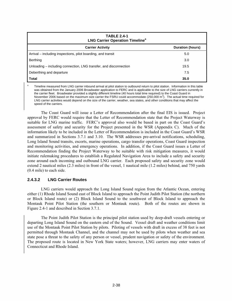
2-38
TABLE 2.4-1
LNG Carrier Operation Timelinea
Carrier Activity Duration (hours)
Arrival – including inspections, pilot boarding, and transit 5.0
Berthing 3.0
Unloading – including connection, LNG transfer, and disconnection 19.5
Deberthing and departure 7.5
Total 35.0
a Timeline measured from LNG carrier inbound arrival at pilot station to outbound return to pilot station. Information in this table was obtained from the January 2006 Broadwater application to FERC and is applicable to the size of LNG carriers currently in the carrier fleet. Broadwater provided a slightly different timeline (40 hours total time required) to the Coast Guard in November 2006 based on the maximum size carrier the FSRU could accommodate (250,000 m3). The actual time required for LNG carrier activities would depend on the size of the carrier, weather, sea states, and other conditions that may affect the speed of the carriers.
The Coast Guard will issue a Letter of Recommendation after the final EIS is issued. Project approval by FERC would require that the Letter of Recommendation state that the Project Waterway is suitable for LNG marine traffic. FERC’s approval also would be based in part on the Coast Guard’s assessment of safety and security for the Project presented in the WSR (Appendix C). Much of the information likely to be included in the Letter of Recommendation is included in the Coast Guard’s WSR and summarized in Sections 3.7.1 and 3.10. The WSR addresses pre-arrival notifications, scheduling, Long Island Sound transits, escorts, marine operations, cargo transfer operations, Coast Guard inspection and monitoring activities, and emergency operations. In addition, if the Coast Guard issues a Letter of Recommendation finding the Project Waterway to be suitable with risk mitigation measures, it would initiate rulemaking procedures to establish a Regulated Navigation Area to include a safety and security zone around each incoming and outbound LNG carrier. Each proposed safety and security zone would extend 2 nautical miles (2.3 miles) in front of the vessel, 1 nautical mile (1.2 miles) behind, and 750 yards (0.4 mile) to each side.
2.4.3.2 LNG Carrier Routes
LNG carriers would approach the Long Island Sound region from the Atlantic Ocean, entering either (1) Rhode Island Sound east of Block Island to approach the Point Judith Pilot Station (the northern or Block Island route) or (2) Block Island Sound to the southwest of Block Island to approach the Montauk Point Pilot Station (the southern or Montauk route). Both of the routes are shown in Figure 2.4-1 and described in Section 3.7.1.
The Point Judith Pilot Station is the principal pilot station used by deep-draft vessels entering or departing Long Island Sound on the eastern end of the Sound. Vessel draft and weather conditions limit use of the Montauk Point Pilot Station by pilots. Piloting of vessels with draft in excess of 38 feet is not permitted through Montauk Channel, and the channel may not be used by pilots when weather and sea state pose a threat to the safety of any person or vessel, prudent navigation or safety of the environment. The proposed route is located in New York State waters; however, LNG carriers may enter waters of Connecticut and Rhode Island.
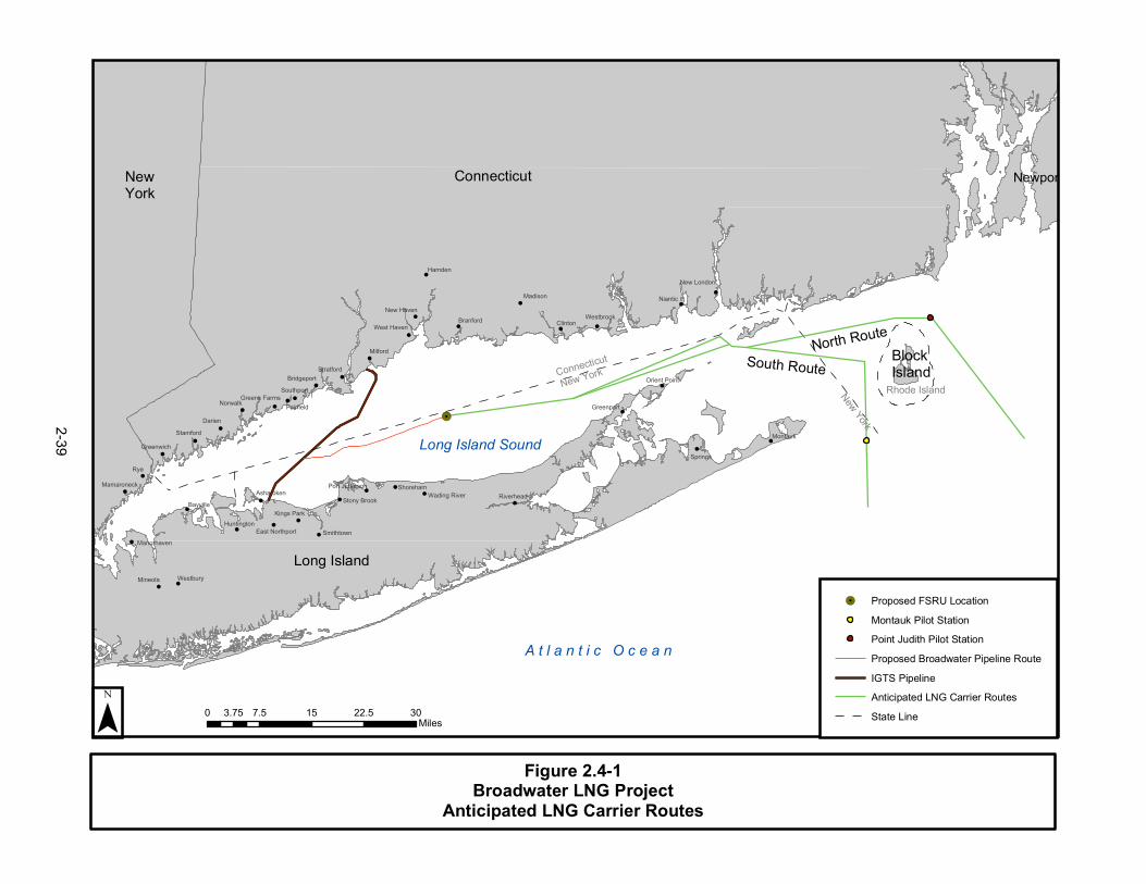
Figure 2.4-1Broadwater LNG Project
Anticipated LNG Carrier Routes
!.
!
!
!
!
!
!
!
!
!
!
!
!
!
!
!
!
!
!
!
!
!
!
!
!
!
!
!
!
!
!
!
!
!
!
!
!
!
!
!
Connecticut
New YorkRhode Island
Block Island
New York
A t l a n t i c O c e a n
Newport Co
Rye
Hamden
Darien
Westbury
Springs
Madison
Norwalk
Niantic
Milford
Clinton
Montauk
Mineola
Shoreham
Branford
Stamford
Westbrook
Bayville
Stratford
Southport
New Haven
Greenwich
Fairfield
Smithtown
Riverhead
Greenport
Asharoken
New London
West Haven
Bridgeport
Manorhaven
Mamaroneck
Kings ParkHuntington
Stony Brook
Orient Point
Wading River
Greens Farms
Port Jefferson
East Northport
¯ 0 7.5 15 22.5 303.75Miles
!. Proposed FSRU LocationMontauk Pilot StationPoint Judith Pilot StationProposed Broadwater Pipeline RouteIGTS PipelineAnticipated LNG Carrier RoutesState Line
Connecticut
Long Island
Long Island Sound
North RouteSouth Route
NewYork
2-39

2-40
2.4.4 Onshore Support Facilities
Onshore support facilities would be required for operation of the FSRU and the pipeline. Permanent onshore support facilities would be established within an existing waterfront industrial site in either Greenport or Port Jefferson, New York (see Figures 2.1-1, 2.4-2, and 2.4-3). These facilities would include office space for 6 to 10 staff; a warehouse for storage and handling of spare parts, tools, and equipment; dock space for berthing four tugs; a workshop for tug maintenance; and a waterfront staging area capable of supporting container transfer cranes, large trucks, and a personnel transfer and boarding area. Apart from the installation of a perimeter security fence and guardpost, Broadwater does not anticipate modifying the existing facilities in any way. Broadwater has indicated that either site would be suitable for onshore support activities.
We received a comment requesting transit times for tugs from either of the proposed onshore support facilities (Port Jefferson or Greenport, New York). In response to an Environmental Information Request, Broadwater provided supplemental information in a filing on March 26, 2007 (available in Docket Number CP06-54). At a speed of 12 knots, tugs based in Port Jefferson would take 1.3 hours to reach the FSRU, 4.4 hours to rendezvous with an LNG carrier 3 miles east of the Race, 6.3 hours to reach the Point Judith Pilot Station, and 5.8 hours to reach the Montauk Point Pilot Station. Tugs based in Greenport would take 3.3 hours to reach the FSRU, 1.4 hours to rendezvous with an LNG carrier 3 miles east of the Race, 3.3 hours to reach the Point Judith Pilot Station, and 2.5 hours to reach the Montauk Point Pilot Station.
2.5 SCHEDULE
After receipt of authorization and certification from FERC and all other necessary permits and approvals for the Project, Broadwater would initiate detailed engineering and design studies. Design and fabrication of the FSRU and YMS would require approximately 3 years from the date of authorization for the Project.
As currently planned by Broadwater, pipeline installation would begin with pre-lay surveys that would start in September 2009. In-water work on pipeline installation would begin in October 2009 and would be completed by the end of April 2010. The YMS would be installed from about the middle of September through the middle of November 2010. Connection of the new pipeline to the YMS and to the IGTS pipeline would take place in November 2010. Broadwater has proposed that the FSRU would be connected to the YMS in December 2010, and that the Project would be in service in late December 2010.
2.6 ENVIRONMENTAL COMPLIANCE INSPECTION AND MITIGATION MONITORING
In preparing construction drawings and specifications for the Project, Broadwater would incorporate all mitigation measures identified in its application as well as requirements of federal, state, and local agencies. Contractors would be provided copies of applicable environmental permits and would be fully apprised of mitigation requirements and other applicable environmental commitments.
All construction personnel would be trained by Broadwater to ensure that they understand and are able to properly implement all mitigation measures stipulated by FERC and other environmental regulatory agencies. Such training would be conducted before commencement of construction and during construction, as needed.

G r e e n p o r t H a r b o rG r e e n p o r t H a r b o r
F a n n i n g P o i n t
F a n n i n g P o i n t
D e r i n gP o i n t
D e r i n gP o i n t
S t i r l i n g B a s i nS t i r l i n g B a s i n
G r e e n p o r tG r e e n p o r t
Figure 2.4-2Broadwater LNG Project
Proposed Greenport Onshore Facility Location
¯ 0 0.07 0.14 0.21 0.280.035Miles
Source: New York State GIS Information Clearinghouse, 2004
LegendGeneral Location of Proposed Onshore Facility
2-41
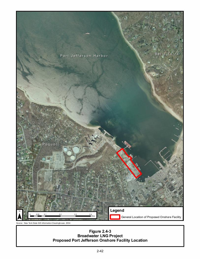
P o r t J e f f e r s o n H a r b o rP o r t J e f f e r s o n H a r b o r B e l l e T e r r eB e l l e T e r r e
P o q u o t tP o q u o t t
Figure 2.4-3Broadwater LNG Project
Proposed Port Jefferson Onshore Facility Location
¯ 0 0.1 0.2 0.3 0.40.05Miles
Source: New York State GIS Information Clearinghouse, 2004
LegendGeneral Location of Proposed Onshore Facility
2-42
2-43
Broadwater would select a Chief Inspector, who would be responsible for quality assurance and compliance with mitigation measures, other applicable regulatory requirements, and other monitoring and reporting specifications. The Chief Inspector would be assisted by one or more full-time Environmental Inspectors, who would report directly to the Chief Inspector and would have the authority to stop work. The Environmental Inspector’s duties would include ensuring compliance with environmental conditions attached to (1) any FERC authorization, (2) other permits or authorizations, or (3) Broadwater’s environmental designs and specifications.
In addition, FERC staff, other regulatory agency personnel, and representatives of the ship classification society (see Section 2.4.1) would conduct inspections to monitor the Project for compliance with the applicable environmental conditions.
2.7 FUTURE PLANS AND ABANDONMENT
Based on economic projections, Broadwater anticipates that the facilities would have a minimum useful life of 30 years, although the FSRU and pipeline could be maintained and operated for 50 years or more. Any future abandonment would be subject to regulatory reviews that would be based on the federal, state, and local regulations in effect at that time.
2.7.1 FSRU and YMS
Upon decommissioning, the FSRU would be removed from the YMS and towed to a shipyard for reuse or recycling. The mooring tower likely would be removed from the seafloor and towed to a shipyard for recycling.
2.7.2 Subsea Pipeline
At the end of the Project, Broadwater would assess the condition of the subsea pipeline to determine whether to remove the pipeline or abandon it in place. The stipulations of the easement with NYSOGS also would dictate Broadwater’s options for abandonment of the pipeline. Abandonment of the pipelines would be in compliance with regulations that are applicable and in force at the time of the abandonment. At this time, if Broadwater were to abandon its pipeline, the abandonment would be subject to approval by FERC under Section 7(b) of the NGA, and COE’s and DOT’s abandonment regulations. An appropriate level of environmental review would be completed at the time that the application for abandonment is filed. Prior to removal or abandonment, the pipeline would be pigged to remove any scale or debris, purged with inert gas, and sealed. If the pipeline were to be removed, it would be cut, raised to a salvage barge, and brought to shore for recycling.