PDF, 12155 KB - Bermad
208
Water Control Solutions BERMAD Irrigation Hydraulic Control Valves
Transcript of PDF, 12155 KB - Bermad

i n f o @ b e r m a d . c o m • w w w . b e r m a d . c o mT h e i n f o r m a t i o n h e r e i n i s s u b j e c t t o c h a n g e w i t h o u t n o t i c e . B E R M A D s h a l l n o t b e h e l d l i a b l e f o r a n y e r r o r s . A l l r i g h t s r e s e r v e d .© Copy r igh t by BERMAD. PCXAE00 09/06
BE
RM
AD
Irriga
tion
Hy
dra
ulic C
on
trol V
alves
W a t e r C o n t r o l S o l u t i o n s
BERMAD IrrigationHydraulic Control Valves
BERMAD IrrigationHydraulic Control Valves

Gilad Ben-Dror: Marketing concept and project managementEnav Waternets: Professional concept, text, and production managementStudio Oz: Graphic concept, design and productionRami Levkovich: Technical consultant

BERMAD IrrigationHydraulic Control ValvesBERMAD Irrigation
Hydraulic Control Valves
BERMAD Irrigation
About this Catalog
This catalog presents a broad overview of the BERMAD main product lines for irrigation projects.With irrigation representing its earliest challenge and serving as the springboard for development into other areas, BERMAD’sirrigation products are the culmination of years of hands-on experience, while reflecting BERMAD’s cumulative engineeringand marketing savvy. Over the years BERMAD has expanded both its manufacturing and its R&D capabilities in order tomeet every market need, resulting in the development and marketing of no less than twelve different product lines. In orderto make it easier to choose the best possible product for each specific need, this catalog focuses on the 100, 400 & 900Series product lines, presenting detailed and clear guidelines.
Unique in its approach the Catalog is organized from the viewpoint of the irrigation project designer, from the laterals tothe water source. Products are subsequently divided into four main chapters based on the location of each system in theirrigation project:
■ Main Network – This is the part of the project that pertains to the water source and includes major system componentssuch as booster and deep well pump stations, reservoirs, main supply lines, pressure and flow control devices, etc.
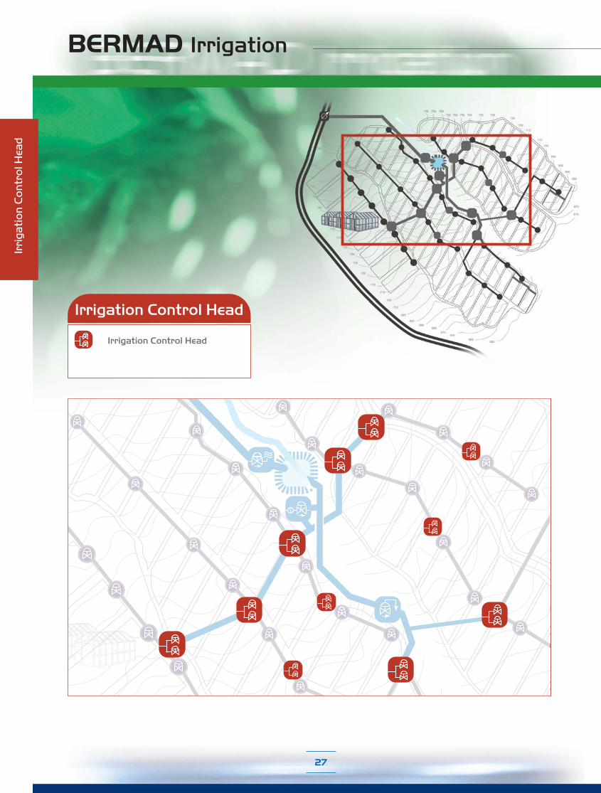
■ Irrigation Control Head – Here the water supply system is transformed to an Irrigation System. These Irrigation Centersinclude various types of large size control valves in a variety of applications.
■ Infield Head-Works – Located on the Riser Lines at the entrance from the supply network to the distribution lines theInfield Head-Works serves as the system control of the water’s final exit through the emitters. It includes various types ofelectric or hydraulic on/off remote control valves, which suit a variety of pressure and flow control applications.
■ Infield System – These models are applied directly to the distribution lines of systems that require additional controlsuch as systems irrigated by non-compensated emitters, systems with high elevation differential, systems with turbid water,sloppy margin systems, etc. Some of the most common components of Infield System are: Pressure Reducers,Anti-Drain Valves and Flush-'n-Stop Valves.
In addition the catalog also includes two more chapters:
■ Engineering – A comprehensive technical section presents the updated relevant information about the BERMAD Series.
■ Accessories – Presents full information about BERMAD's control accessories and system components.
The full range of control valves for the irrigation market is so extensive that we have confined ourselves in this catalog toa select number of models. Contact your BERMAD representative for information on additional models.
Despite our efforts to achieve perfection, if any errors have crept into the catalog, we would appreciatereceiving your feedback.
All the Photos, Applications and Operation Drawings in this Catalog are for Illustration purpose.The information herein is subject to change without notice.BERMAD shall not be held liable for any errors contained herein. All rights reserved © Copyright by BERMAD

BERMAD Company Profile
BERMAD - Provider of Solutions
Based on expertise that comes from years of hands-on experience, BERMAD has developedstate-of-the-art control valves and related products, along with comprehensive system solutionsfor a range of water management needs. Its main areas of activity include:
Irrigation
A comprehensive line of water control products provides system solutions for the full range of agriculturalirrigation such as drip irrigation, pivot systems, sprinklers, micro-jets and greenhouse irrigation, as well ascommercial and residential gardening irrigation needs.
Waterworks
BERMAD offers systems for water and wastewater supply and treatment facilities ranging from municipalities,high-rise buildings, to whole industrial water systems, hydroelectric power stations and private sectorprojects.
Fire Protection
Automatic control valves with a range of operation modes for fire protection systems in oil refineries,petro-chemical plants and public buildings.
Petroleum
Automatic, self-actuated control valves for the petroleum industry, implementedin distribution terminals, cross-country pipelines and petroleum tank farms.
Water metering
BERMAD solutions are adapted to the needs of bulk and domestic water metering in supply systems,and include remote water metering read-out and pre-payment systems.
Helping control the world’s most precious resourceEfficient, smart management of our planet’s most precious resources is as vital as the resource itself.BERMAD water management solutions offer nothing less.
Founded in 1965, BERMAD knows the value of a single drop of water and how best to reap its full advantage.Today BERMAD serves global customers in a wide range of fields. Bringing together its expertise andknow-how, leading-edge technology and precision engineering, BERMAD provides comprehensivecustomized solutions for the control and management of water supply anywhere in the world.
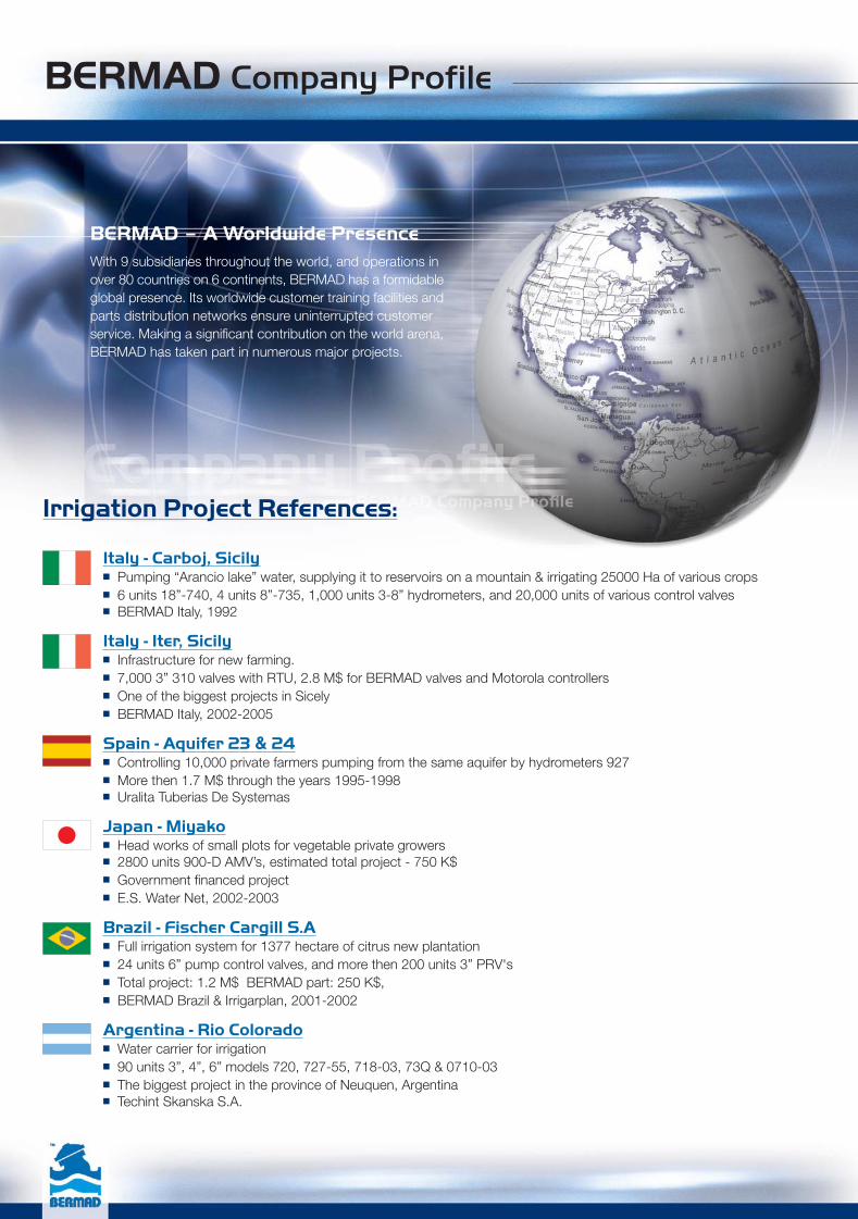
BERMAD – A Worldwide PresenceWith 9 subsidiaries throughout the world, and operations inover 80 countries on 6 continents, BERMAD has a formidableglobal presence. Its worldwide customer training facilities andparts distribution networks ensure uninterrupted customerservice. Making a significant contribution on the world arena,BERMAD has taken part in numerous major projects.
BERMAD Company Profile
Irrigation Project References:
Italy - Carboj, Sicily■ Pumping “Arancio lake” water, supplying it to reservoirs on a mountain & irrigating 25000 Ha of various crops■ 6 units 18”-740, 4 units 8”-735, 1,000 units 3-8” hydrometers, and 20,000 units of various control valves■ BERMAD Italy, 1992
Italy - Iter, Sicily■ Infrastructure for new farming.■ 7,000 3” 310 valves with RTU, 2.8 M$ for BERMAD valves and Motorola controllers■ One of the biggest projects in Sicely■ BERMAD Italy, 2002-2005
Spain - Aquifer 23 & 24■ Controlling 10,000 private farmers pumping from the same aquifer by hydrometers 927■ More then 1.7 M$ through the years 1995-1998■ Uralita Tuberias De Systemas
Japan - Miyako■ Head works of small plots for vegetable private growers■ 2800 units 900-D AMV’s, estimated total project - 750 K$■ Government financed project■ E.S. Water Net, 2002-2003
Brazil - Fischer Cargill S.A■ Full irrigation system for 1377 hectare of citrus new plantation■ 24 units 6” pump control valves, and more then 200 units 3” PRV's■ Total project: 1.2 M$ BERMAD part: 250 K$,■ BERMAD Brazil & Irrigarplan, 2001-2002
Argentina - Rio Colorado■ Water carrier for irrigation■ 90 units 3”, 4”, 6” models 720, 727-55, 718-03, 73Q & 0710-03■ The biggest project in the province of Neuquen, Argentina■ Techint Skanska S.A.

BERMAD Company Profile
USA - Salt Water Intrusion / Irrigation Project, Monterey, California■ Artichoke and Strawberry irrigation■ 20 units 6” & 8” 772-55 controlling the head works of the farms■ BERMAD USA
China - Yangze River■ Irrigation of new plantation from the flood of the three gorges dam■ More then 250 valves 4”-8” 420, first phase of one of the biggest projects in the world■ BERMAD China & Netafim
Israel - Kolchey Eilat■ Treating, delivering (60 Km.), storing & pumping the city of Eilat wastewater for irrigation in the Negev desert■ 25 units 4-10” 720, 730 & 73Q, 10 units 4-8” 920 & 130 units 3x3-350■ 200 K$■ AGAT Engineering, Ardom Association & BERMAD Israel
Palestinian Authority - Jericho■ Conversion from open canals flood irrigation to pressurized drip irrigation■ 250 units 927-DD installed on hydrants■ BERMAD Part - 250 K$■ Italian finance, USA supervision■ Anera, 2003
Japan - Shizoka Perfecture■ Tee trees irrigation systems■ 2000 units 2” 220 valves + 500 units 2” 900-D■ Estimated total project - 500 K$, government finance■ E.S. Water Net
Philippines - Mindanao Irrigation■ Banana plantation for Dole & Delmonte companies■ 120 units 4 – 6” 420 & 740■ Netafim
USA - Strawberry Farms, Salinas, California■ Strawberry farm, buried irrigation application■ 160 units 3”L 120-55 + 50 units 2” 220-55■ BERMAD USA
Argentina - Jujuy■ Water carrier for irrigation■ 12 units 14”, 18” & 20” model 753-67-49■ Tecnoflow S.A.
USA - Nut Tree Farming■ Almond trees, Buried irrigation application■ More then 5,000 units 2” 220 Through the years 1995 to 2005■ BERMAD USA
Israel - Hof Karmel■ Water desalination for Irrigation through a reservoir with pump station■ 10 units 6-12" 750/720/730 + 50 un. 4-8" AMV's + 300 2" AMV's, BERMAD Part -More then 250 K$■ BERMAD & Netafim
USA - Nut Tree Farming■ Almond Trees, buried Irrigation application■ 260 units 3”L 120 valves, first phase of a farm in Bakersfield CA■ BERMAD USA

770 765 760755 750 745 740 735 730
725
720
715
710
705
700
695
690
685
670
675
785
780
775
770
765
760
755
750
745
740
735
730
725
720
715
710
705
700
695
690
685680
675670
665660
BERMAD Irrigation
User Guide

Infield Head-Works
■ On/Off Control■ Pressure Reducing, Standard■ Pressure Reducing, Drip-Tape■ Pressure Reducing & Sustaining■ Pressure Sustaining■ Flow Control■ Flow Control & Pressure Reducing
Main Network
■ Reservoirs■ Pumping Stations■ Pressure Reducing■ Pressure Relief■ Pressure Relief/Sustaining
Irrigation Control Head
■ On/Off Control■ Pressure Reducing■ Pressure Relief■ Flow Control■ Pressure Sustaining■ Filter Stations
■ Pressure Reducing■ Anti-Drain■ Flush-’n-Stop
Infield System
User Guide

BERMAD Irrigation
Table of Contents
Group Page No.
BERMAD Model Selection Guide page 1-4
IR-400 Valve Data page 5
IR-100 hYflow Valve Data page 6
IR-900-M Hydrometer Data page 7
IR-900-D Automatic Metering Valve Data page 8
WW-700 Double Chamber Valve Data page 9
Main Network page 10Main Network Application Guide page 11-12
Level Control Valves page 13-14
Pumping Station Valves page 15-16
Pressure Reducing Valves page 17-20
Pressure Relief Valves page 21-22
Pressure Sustaining Valves page 23-24
Irrigation Control Head page 26Irrigation Control Head Application Guide page 27-28
On/Off Control Valves page 29-32
Pressure Reducing Control Valves page 33-36
Pressure Reducing & Sustaining Control Valves page 37-40
Pressure Relief Valves page 41-42
Flow Control Valves page 43-46
Pressure Sustaining Control Valves page 47-50
Filter Station Control Valves page 51-54
Infield Head-Works page 56Infield Head-Works Application Guide page 57-58
On/Off Control Valves page 59-62
Pressure Reducing Control Valves for Standard Systems page 63-66
Pressure Reducing Control Valves for Drip-Tape Applications page 67-70
Pressure Reducing & Sustaining Control Valves page 71-74
Pressure Sustaining Control Valves page 75-78
Flow Control Valves page 79-82
Flow Control & Pressure Reducing Valves page 83-86

BERMAD Irrigation
■ Pictures and drawings are for presentation only
■ Bermad reserves the right to make any product changes without prior notice
■ For further details please see our Comprehensive Irrigation Catalog
■ Special technical documentation must be requested seperately
Group Page No.
Infield Systems page 88Infield Systems Application Guide page 89-90
Pressure Reducing for Infield Systems page 91-94
Anti-Drain Valves page 95
Flush-’n-Stop Valves page 96
Engineering Data page 98-99IR-400 Series Engineering Data page 100-109
IR-100 Series Engineering Data page 110-116
IR-900-M Series Engineering Data page 117-130
IR-900-D Series Engineering Data page 131-140
WW-700 Series Engineering Data page 141-152
Water Meters Engineering Data page 153-158
IR-350 Series Engineering Data page 159-163
IR-200 Series Engineering Data page 164-168
IR-300 Series Engineering Data page 169-172
IR-R00 Series Engineering Data page 173-176
PRV Series Engineering Data page 177-181
AR Series Engineering Data page 182-186
Accessories page 188Mini-Pilots page 190-191
Pilots page 192-195
Solenoids page 196-198
Latching Solenoids page 199-200
Accessories & Components page 201-204
System Components page 205-207
BERMAD Irrigation
1
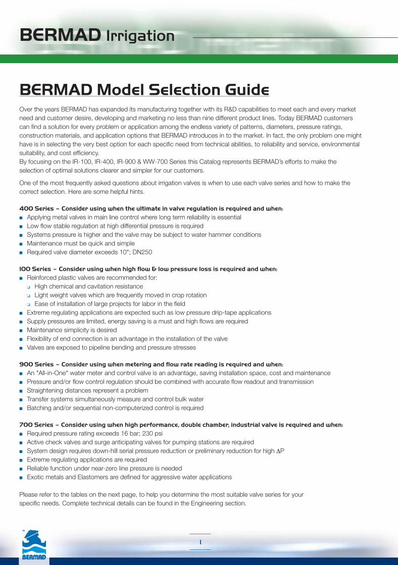
BERMAD Model Selection GuideOver the years BERMAD has expanded its manufacturing together with its R&D capabilities to meet each and every market need and customer desire, developing and marketing no less than nine different product lines. Today BERMAD customers can find a solution for every problem or application among the endless variety of patterns, diameters, pressure ratings, construction materials, and application options that BERMAD introduces in to the market. In fact, the only problem one might have is in selecting the very best option for each specific need from technical abilities, to reliability and service, environmental suitability, and cost efficiency. By focusing on the IR-100, IR-400, IR-900 & WW-700 Series this Catalog represents BERMAD’s efforts to make the selection of optimal solutions clearer and simpler for our customers.
One of the most frequently asked questions about irrigation valves is when to use each valve series and how to make the correct selection. Here are some helpful hints.
400 Series – Consider using when the ultimate in valve regulation is required and when:■ Applying metal valves in main line control where long term reliability is essential ■ Low flow stable regulation at high differential pressure is required■ Systems pressure is higher and the valve may be subject to water hammer conditions■ Maintenance must be quick and simple ■ Required valve diameter exceeds 10"; DN250
100 Series – Consider using when high flow & low pressure loss is required and when:■ Reinforced plastic valves are recommended for: ❏ High chemical and cavitation resistance ❏ Light weight valves which are frequently moved in crop rotation ❏ Ease of installation of large projects for labor in the field■ Extreme regulating applications are expected such as low pressure drip-tape applications■ Supply pressures are limited, energy saving is a must and high flows are required■ Maintenance simplicity is desired■ Flexibility of end connection is an advantage in the installation of the valve■ Valves are exposed to pipeline bending and pressure stresses
900 Series – Consider using when metering and flow rate reading is required and when:■ An "All-in-One" water meter and control valve is an advantage, saving installation space, cost and maintenance■ Pressure and/or flow control regulation should be combined with accurate flow readout and transmission■ Straightening distances represent a problem■ Transfer systems simultaneously measure and control bulk water■ Batching and/or sequential non-computerized control is required
700 Series – Consider using when high performance, double chamber, industrial valve is required and when:■ Required pressure rating exceeds 16 bar; 230 psi■ Active check valves and surge anticipating valves for pumping stations are required■ System design requires down-hill serial pressure reduction or preliminary reduction for high ΔP ■ Extreme regulating applications are required■ Reliable function under near-zero line pressure is needed■ Exotic metals and Elastomers are defined for aggressive water applications
Please refer to the tables on the next page, to help you determine the most suitable valve series for your specific needs. Complete technical details can be found in the Engineering section.
BERMAD Irrigation
2
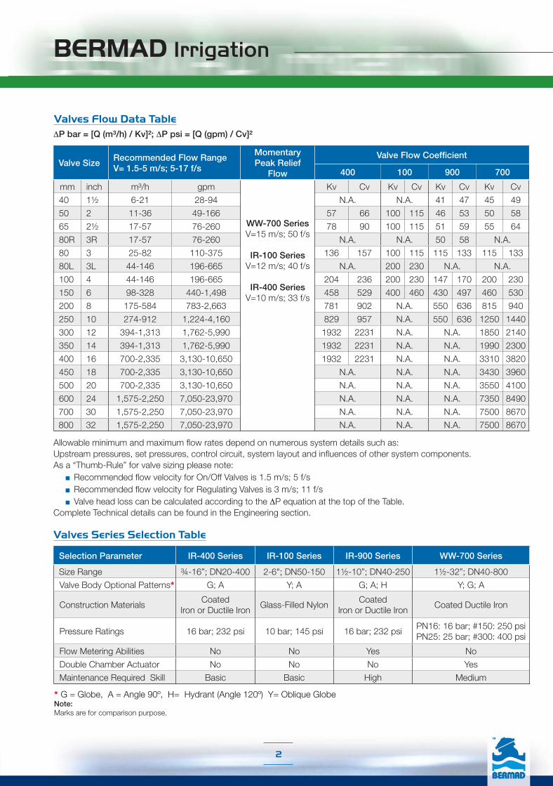
Valves Flow Data TableΔP bar = [Q (m³/h) / Kv]²; ΔP psi = [Q (gpm) / Cv]²
Allowable minimum and maximum flow rates depend on numerous system details such as: Upstream pressures, set pressures, control circuit, system layout and influences of other system components. As a “Thumb-Rule” for valve sizing please note: ■ Recommended flow velocity for On/Off Valves is 1.5 m/s; 5 f/s ■ Recommended flow velocity for Regulating Valves is 3 m/s; 11 f/s ■ Valve head loss can be calculated according to the ΔP equation at the top of the Table.Complete Technical details can be found in the Engineering section.
Valve SizeRecommended Flow Range V= 1.5-5 m/s; 5-17 f/s
MomentaryPeak Relief
Flow
Valve Flow Coefficient
400 100 900 700
mm inch m³/h gpm
WW-700 Series V=15 m/s; 50 f/s
IR-100 SeriesV=12 m/s; 40 f/s
IR-400 Series
V=10 m/s; 33 f/s
Kv Cv Kv Cv Kv Cv Kv Cv
40 1½ 6-21 28-94 N.A. N.A. 41 47 45 49
50 2 11-36 49-166 57 66 100 115 46 53 50 58
65 2½ 17-57 76-260 78 90 100 115 51 59 55 64
80R 3R 17-57 76-260 N.A. N.A. 50 58 N.A.
80 3 25-82 110-375 136 157 100 115 115 133 115 133
80L 3L 44-146 196-665 N.A. 200 230 N.A. N.A.
100 4 44-146 196-665 204 236 200 230 147 170 200 230
150 6 98-328 440-1,498 458 529 400 460 430 497 460 530
200 8 175-584 783-2,663 781 902 N.A. 550 636 815 940
250 10 274-912 1,224-4,160 829 957 N.A. 550 636 1250 1440
300 12 394-1,313 1,762-5,990 1932 2231 N.A. N.A. 1850 2140
350 14 394-1,313 1,762-5,990 1932 2231 N.A. N.A. 1990 2300
400 16 700-2,335 3,130-10,650 1932 2231 N.A. N.A. 3310 3820
450 18 700-2,335 3,130-10,650 N.A. N.A. N.A. 3430 3960
500 20 700-2,335 3,130-10,650 N.A. N.A. N.A. 3550 4100
600 24 1,575-2,250 7,050-23,970 N.A. N.A. N.A. 7350 8490
700 30 1,575-2,250 7,050-23,970 N.A. N.A. N.A. 7500 8670
800 32 1,575-2,250 7,050-23,970 N.A. N.A. N.A. 7500 8670
Valves Series Selection Table
Selection Parameter IR-400 Series IR-100 Series IR-900 Series WW-700 Series
Size Range ¾-16”; DN20-400 2-6"; DN50-150 1½-10”; DN40-250 1½-32”; DN40-800
Valve Body Optional Patterns* G; A Y; A G; A; H Y; G; A
Construction MaterialsCoated
Iron or Ductile IronGlass-Filled Nylon
Coated Iron or Ductile Iron
Coated Ductile Iron
Pressure Ratings 16 bar; 232 psi 10 bar; 145 psi 16 bar; 232 psiPN16: 16 bar; #150: 250 psi PN25: 25 bar; #300: 400 psi
Flow Metering Abilities No No Yes No
Double Chamber Actuator No No No Yes
Maintenance Required Skill Basic Basic High Medium
* G = Globe, A = Angle 90º, H= Hydrant (Angle 120º) Y= Oblique GlobeNote:Marks are for comparison purpose.

BERMAD Irrigation
3
Valve Control Features:
After selecting the proper valve series, one can choose from over 200 valve models, the desired model according to valve location in the project and its required application as defined by its control features.
1. Main Feature/s – Selection of the suitable model requires proper definition of the valve main control featureor features:■ Pressure Reducing■ Pressure Sustaining■ Flow Control■ Solenoid Control■ Combination of the above, etc. These features and others, enable the control valve to meet and answer system needs at a specific location.
2. Additional Feature/s – Proper definition of additional control features enables utilization of the control valve’s potential to the fullest, in the following ways:■ Add-on of automatic functions that support and complete the valve main feature: ❏ Downstream over-pressure guard ❏ Closing-surge prevention ❏ Check feature ❏ Hydraulic override, etc.■ Determining valve status in the project control system, according to needs and control type, as well as environmental calculations and expected skill level of maintenance personnel. ❏ Manual/Hydraulic/Electric - Opening/Closing control ❏ Valve’s desired normal position ❏ Float type definition for level control valves, etc.
2.1 Valve Remote Control Features N.O. Hydraulic Control: ................................. 50 N.C. Hydraulic Control: ................................. 54 Electric Control: ............................................ 55
For Solenoid Control Confirm: ■ Desired voltage and valve's normal position ■ Controller abilities & requirements ■ Lightning probability
Calculate wire size in accordance with: ❑ System pressure conditions ❑ Solenoid's power consumption, quantity & distance
Remote Control Options Comparison Table
ParameterFeature Simplicity Fail-Safe Plots with
SlopeRemote Valves
Multiple Valves
Valve Response
50 ++++ Open + ++ ++ Delayed
54 +++ Close +++ ++++ ++++ Immediate
55 +++ Close ++++ ++++ ++++ Immediate

BERMAD Irrigation
4
Valve Control Circuit:
After defining the valve control features, the applications designer must select the suitable control circuit type (2-Way, 3-Way, 2/3-Way servo) for the application, considering network hydraulic and topographic conditions, water quality, required accuracy and sensitivity levels, etc.Consider the information below as a guide when selecting the control circuit type:
■ 2-Way Control Use when very accurate control is required in clean filtered water supply or dirty water with sediments. Works well in dynamic or static flow condition. Note that applying a 2-way control circuit has a small additional head loss across the valve in low and medium flow-rates ("V" below 2 m/s).
■ 3-Way Control (mark = X)Use in applications where the water qualities can either be clean or dirty which includes some organic matter. 3-way control will enable the valve to fully open if required during high flow irrigation shifts; when the valve is required to fully open with minimal head loss.
■ Servo 3/2-Way Control (mark = b)Use in applications where the water qualities can either be clean or dirty with sediments or organic matter. The Servo 3/2-way pilot should be considered where extreme accuracy and regulation ability is required together with the possibility of dirty water. Especially recommended for pressure reduction of low pressure Drip-Tape (non compensated) irrigation systems.
Control Circuit Comparison: 2-Way Control Circuit ........................................ Default■ Online accurate, quick respond requlation■ Very low set point■ Very high accuracy 3-Way Control Circuit ........................................ X■ Fully opens at low supply pressure■ Easy conversion from/to 2/3-way 2/3-Way Control Circuit ..................................... b■ Very low set point■ Very high accuracy■ Dynamic integrated needle valve■ Upstream Setting pressure limit – 4 bar; 60 psi
Parameter Circuit
Sensitivity Accuracy StabilityMinimum Setting
Clogging Risk External BleedSediments
Organic Matter
2-Way ++++ +++ +++ Very Low Low Medium No
3-Way ++ ++ ++++ Low Fair Low Yes
2/3-Way ++++ ++++ ++++ 0.5bar; 7psi Low Low No
Control Circuit Options Comparison Table

BERMAD Irrigation
5
IR-400 Basic Valve
The basic Model IR-400 diaphragm actuated hydraulically operated valve is at the leading edge of control valve design. It combines simple and reliable construction with superior performance, while at the same time being virtually free of the typical limitations associated with other single chambered valves. These automatic water control valves are designed for vertical or horizontal installation and are available in diameter sizes of 2-16”; DN50- DN400, in a wide range of materials and end connections.
The design of the IR-400 valve body includes a full bore seat with unobstructed flow path, free of any in-line ribs, supporting cage, or shafts.
The unique hydro-dynamic globe design provides high flow capabilities with minimum head loss. The cover is removable via four (4) fastening bolts (up to 10”) for quick in-line inspection and service. The internal design of the IR-400 valve is based on innovative technology using advanced rubber-based materials to achieve a solid, one piece elastomeric assembly including a flexible fabric reinforced diaphragm, vulcanized with a rugged radial seal disk. The diaphragm is carefully balanced and peripherally supported to avoid distortion and to protect the elastomer, resulting in long-life and controlled actuation even under harsh conditions. One diaphragm and spring fully meet the valve’s operating pressure range requirements. The diaphragm assembly can be easily removed from the valve body with no need for disassembling the valve from the line.
The Model IR-400 Basic Valve uses valve differential pressure to power the diaphragm assembly open or closed. The lower side of the diaphragm, which serves to cushion the closing of the valve, is exposed to downstream pressure through a dynamic peripheral passageway that its width responds to differential pressure and flow along the downstream side of the valve. The pressure in the control chamber varies, usually resulting from the combined action of a regulating pilot and a fixed orifice. This varying pressure modulates the valve to open or close.
Basic Valve

BERMAD Irrigation
6
IR-100 hYflow Basic Valve
The BERMAD basic Model IR-100 hYflow diaphragm actuated, hydraulically operated valve is at the leading edge of control valve design. It combines simple and reliable construction with superior performance, while at the same time being virtually free of the typical limitations associated with standard control valves. BERMAD’s automatic water control valves are designed for vertical or horizontal installation and are available in sizes of 2”, 21/2”, 3”, 4” & 6”; DN: 50, 65, 80, 100 & 150.
The Model IR-100 hYflow, made from industrial durable glass-filled nylon, is engineered to meet rough service conditions with high chemical and cavitation resistance.
The hYflow ‘Y’ valve body design includes a full bore seat with unobstructed flow path, free of any in-line ribs, supporting cage, or shafts. Its unitized Flexible Super Travel (FST) diaphragm and guided plug provide a significantly ‘look through’ passage from end to end resulting in ultra-high flow capacity with minimal pressure loss. The combination of a long travel guided valve plug, peripherally supported diaphragm, and replaceable valve seal provides:
■ No chattering or slamming closed■ Accurate and stable regulation with smooth motion■ Low operating pressure requirements■ No diaphragm erosion and distortion■ Diaphragm and spring fully meet the valve’s operating
pressure range requirements.Designed for service under a wide range of pressure and flow conditions, from dripping to maximum flow, the IR-100 hYflow excels at being a user-friendly control valve:■ Simple design with few parts guarantees easy in-line
inspection and service.■ Adaptable on-site to a wide range of end connection
types and sizes. ■ Articulated flange connections isolate the valve from pipeline bending and pressure stresses.
Basic Valve
BERMAD Irrigation
7
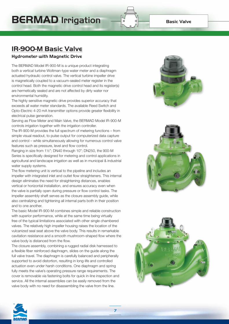
IR-900-M Basic ValveHydrometer with Magnetic Drive
The BERMAD Model IR-900-M is a unique product integrating both a vertical turbine Woltman-type water meter and a diaphragm actuated hydraulic control valve. The vertical turbine impeller drive is magnetically coupled to a vacuum-sealed meter register in the control head. Both the magnetic drive control head and its register(s) are hermetically sealed and are not affected by dirty water nor environmental humidity. The highly sensitive magnetic drive provides superior accuracy that exceeds all water meter standards. The available Reed Switch and Opto-Electric 4-20 mA transmitter options provide greater flexibility in electrical pulse generation. Serving as Flow Meter and Main Valve, the BERMAD Model IR-900-M controls irrigation together with the irrigation controller.The IR-900-M provides the full spectrum of metering functions – from simple visual readout, to pulse output for computerized data capture and control – while simultaneously allowing for numerous control valve features such as pressure, level and flow control.Ranging in size from 1½”; DN40 through 10”; DN250, the 900-M Series is specifically designed for metering and control applications in agricultural and landscape irrigation as well as in municipal & industrial water supply systems.The flow metering unit is vertical to the pipeline and includes an impeller with integrated inlet and outlet flow straighteners. This internal design eliminates the need for straightening distances, enables vertical or horizontal installation, and ensures accuracy even when the valve is partially open during pressure or flow control tasks. The impeller assembly shaft serves as the closure assembly guide, while also centralizing and tightening all internal parts both in their position and to one another.The basic Model IR-900-M combines simple and reliable construction with superior performance, while at the same time being virtually free of the typical limitations associated with other single chambered valves. The relatively high impeller housing raises the location of the vulcanized seal seat above the valve body. This results in remarkable cavitation resistance and a smooth mushroom-shaped flow where the valve body is distanced from the flow.The closure assembly, combining a rugged radial disk harnessed to a flexible fiber reinforced diaphragm, slides on the guide along the full valve travel. The diaphragm is carefully balanced and peripherally supported to avoid distortion, resulting in long-life and controlled actuation even under harsh conditions. One diaphragm and spring fully meets the valve’s operating pressure range requirements. The cover is removable via fastening bolts for quick in-line inspection and service. All the internal assemblies can be easily removed from the valve body with no need for disassembling the valve from the line.
Basic Valve
BERMAD Irrigation
8
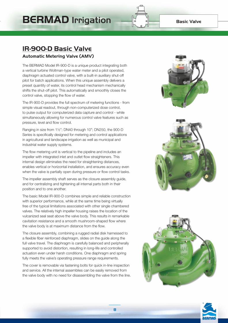
IR-900-D Basic ValveAutomatic Metering Valve (AMV)
The BERMAD Model IR-900-D is a unique product integrating both a vertical turbine Woltman-type water meter and a pilot operated, diaphragm actuated control valve, with a built-in auxiliary shut-off pilot for batch applications. When this unique assembly delivers a preset quantity of water, its control head mechanism mechanically shifts the shut-off pilot. This automatically and smoothly closes the control valve, stopping the flow of water.
The IR-900-D provides the full spectrum of metering functions - from simple visual readout, through non-computerized dose control, to pulse output for computerized data capture and control - while simultaneously allowing for numerous control valve features such as pressure, level and flow control.
Ranging in size from 1½”; DN40 through 10”; DN250, the 900-D Series is specifically designed for metering and control applications in agricultural and landscape irrigation as well as municipal and industrial water supply systems.
The flow metering unit is vertical to the pipeline and includes an impeller with integrated inlet and outlet flow straighteners. This internal design eliminates the need for straightening distances, enables vertical or horizontal installation, and ensures accuracy even when the valve is partially open during pressure or flow control tasks.
The impeller assembly shaft serves as the closure assembly guide, and for centralizing and tightening all internal parts both in their position and to one another.
The basic Model IR-900-D combines simple and reliable construction with superior performance, while at the same time being virtually free of the typical limitations associated with other single chambered valves. The relatively high impeller housing raises the location of the vulcanized seal seat above the valve body. This results in remarkable cavitation resistance and a smooth mushroom-shaped flow where the valve body is at maximum distance from the flow.
The closure assembly, combining a rugged radial disk harnessed to a flexible fiber reinforced diaphragm, slides on the guide along the full valve travel. The diaphragm is carefully balanced and peripherally supported to avoid distortion, resulting in long-life and controlled actuation even under harsh conditions. One diaphragm and spring fully meets the valve’s operating pressure range requirements.
The cover is removable via fastening bolts for quick in-line inspection and service. All the internal assemblies can be easily removed from the valve body with no need for disassembling the valve from the line.
Basic Valve

BERMAD Irrigation
9
WW-700 Basic Valve
The basic Model WW-700/705 diaphragm actuated and the WW-800/805 piston-actuated valves are hydraulically operated, globe valves in either the standard oblique (Y) or angle pattern design. Each valve comprises two major components: the body-seat assembly and the actuator assembly.
The actuator assembly is unitized and is removable from the body as an integral unit. It consists of both an upper and a lower control-chamber.
Each basic valve can easily be configured, on-site, either as a single chamber control valve (Model 705/805), or a double chamber control valve (Model WW-700/800). The shaft sub assembly, in both single and double chambered versions is center guided, providing an unobstructed seat area.
The Model WW-700/800 Basic double chambered valve operation is independent of valve differential pressure since the line pressure actually serves as the actuator differential pressure. This develops maximum power, ensuring immediate valve response. The upper control chamber is pressurized to close, and vented to open the valve. The lower control chamber is usually vented to the atmosphere, but can also be pressurized to power the valve open.
The Model WW-705/805 Basic Valve uses valve differential pressure to power the actuator open or closed. The lower control-chamber, which serves to cushion the closing of the valve, is exposed to the downstream pressure, through a fixed orifice connected to the downstream side of the valve. The pressure in the upper control-chamber varies, usually resulting from the combined action of a regulating pilot and a fixed orifice. This varying pressure modulates the valve to open or close.
The Basic Hydraulic Valve is available in a wide range of materials, sizes, pressure ratings, and end connections. Single or double chambered versions are used as the main valve in all WW-700 and WW-800 Series applications.
Basic Valve

Main NetworkIrrigation system Main Network design and operation starts with careful examinationof the available water sources and the physical conditions of the project regardingexpected flow, pressure, and quality ranges. Based on these parameters, the projectengineer determines the type, size and location of major system components includingpump stations, reservoirs, supply lines, pressure control devices, air release, filtration,and so on.These components are then integrated into the Main Network to achieve continuous,reliable, efficient, and cost-effective irrigation.
Ma
in N
etwo
rkIn
field S
ystem

BERMAD Irrigation
770 765 760755 750 745 740 735 730
725
7
785
780
775
770
765
760
755
750
745
740
Main Network
Main Line
Reservior
Level Control System
Pumping Station
Pressure Reducing System
770 765 760755 750 745 740 735 730
725
7
785
780
775
770
765
760
755
750
745
740
Ma
in N
etw
ork
Infield System
11
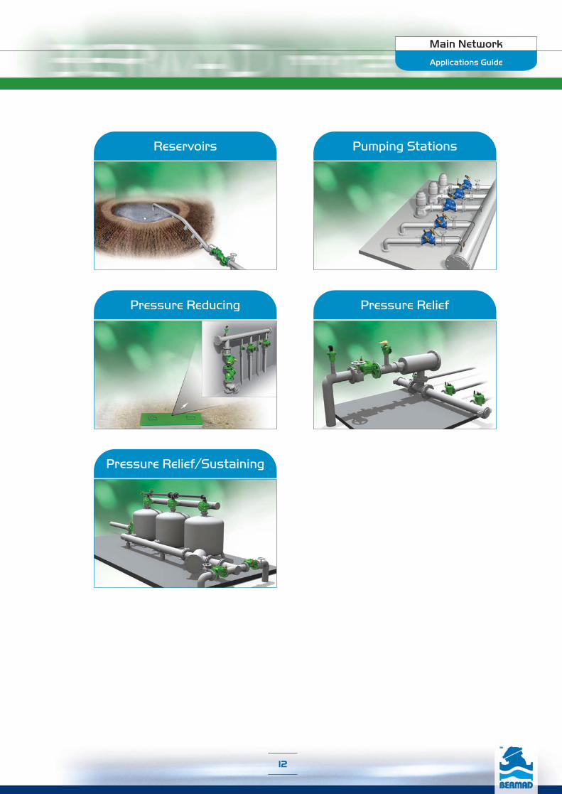
Pressure Reducing
Pressure Relief/Sustaining
Pumping StationsReservoirs
Pressure Relief
Applications Guide
Main Network
12

BERMAD IrrigationReservoirs
Main Network
13
Applications Guide
■ Full Range of Low Level Reservoirs■ Unavailable Power Supply Locations■ Very Low Supply Pressure Systems■ Energy Cost-Critical Systems■ Fertilizer Mixing Tanks (IR-450-60)■ High Level Reservoirs and Water Towers (IR-450-80)■ Level Sustaining at Reservoir Outlet (IR-453)
■ Limited Supply Pressure Systems (IR-453)■ Systems Irrigated Directly from Fill-Up Line (IR-453 & IR-457)■ Backup for Reservoir Supply Valves (IR-453 & IR-457)■ Limited Flow Capacity Systems (IR-457)■ Reservoirs Subject to High Inlet Pressure (IR-457)■ Pressure Breaking Reservoirs in Gravity Fed Lines (IR-457)
Level Control ValvesLevel Control Valves combine the advantages of excellent hydraulic control valves with the simplicity of altitude pilots or mechanical floats. External installation of the main valve eliminates installation and maintenance problems associated with mechanical float valves installed in the reservoir. A wide selection of altitude and float pilot types makes BERMAD Float Control Valves the right solution wherever level control is required.
BERMAD IrrigationReservoirs
Main Network
14
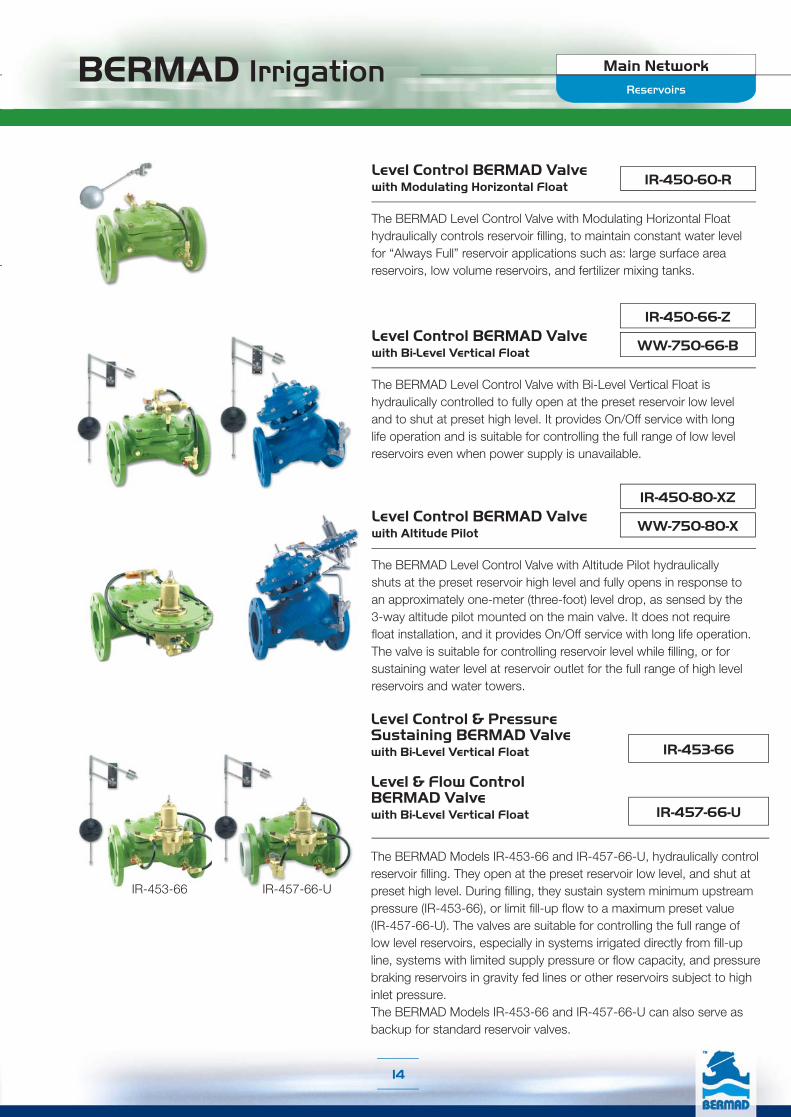
IR-457-66-U
IR-453-66
Level Control & Pressure Sustaining BERMAD Valve with Bi-Level Vertical Float
Level & Flow Control BERMAD Valve with Bi-Level Vertical Float
The BERMAD Models IR-453-66 and IR-457-66-U, hydraulically control reservoir filling. They open at the preset reservoir low level, and shut at preset high level. During filling, they sustain system minimum upstream pressure (IR-453-66), or limit fill-up flow to a maximum preset value (IR-457-66-U). The valves are suitable for controlling the full range of low level reservoirs, especially in systems irrigated directly from fill-up line, systems with limited supply pressure or flow capacity, and pressure braking reservoirs in gravity fed lines or other reservoirs subject to high inlet pressure. The BERMAD Models IR-453-66 and IR-457-66-U can also serve as backup for standard reservoir valves.
WW-750-80-X
IR-450-80-XZLevel Control BERMAD Valve with Altitude Pilot
The BERMAD Level Control Valve with Altitude Pilot hydraulically shuts at the preset reservoir high level and fully opens in response to an approximately one-meter (three-foot) level drop, as sensed by the 3-way altitude pilot mounted on the main valve. It does not require float installation, and it provides On/Off service with long life operation. The valve is suitable for controlling reservoir level while filling, or for sustaining water level at reservoir outlet for the full range of high level reservoirs and water towers.
WW-750-66-B
IR-450-66-ZLevel Control BERMAD Valve with Bi-Level Vertical Float
The BERMAD Level Control Valve with Bi-Level Vertical Float is hydraulically controlled to fully open at the preset reservoir low level and to shut at preset high level. It provides On/Off service with long life operation and is suitable for controlling the full range of low level reservoirs even when power supply is unavailable.
IR-450-60-R Level Control BERMAD Valve with Modulating Horizontal Float
The BERMAD Level Control Valve with Modulating Horizontal Float hydraulically controls reservoir filling, to maintain constant water level for “Always Full” reservoir applications such as: large surface area reservoirs, low volume reservoirs, and fertilizer mixing tanks.
IR-453-66 IR-457-66-U

BERMAD Irrigation Main Network
15
Applications Guide
Pump Control Valves■ Isolates system from the effects of pump start-ups and
stops for:❏ Solitary single speed pumps❏ Battery of single speed pumps (add & switch)❏ Battery of variable speed pumps (add)
■ Pump overload and cavitation protection (WW-743)■ Controlled pipeline fill-up (WW-743)
Surge Anticipating Valves■ Eliminates surge in all pumping systems:
❏ Booster & deep well, single & variable speed■ Eliminates surge in all distribution networks:
❏ Irrigation, municipal, sewage, HVAC ❏ Difficult to maintain, remote locations, older systems
Pumping Station ValvesPump Control Valves protect pumps, pipelines, and other system components by isolating the pipeline from the sudden velocity changes associated with pump start-up and stopping. The “Active Check Valve” operating logic, employs a method of operation of pumping-system control that prevents surges rather than trying to minimize them.Abrupt pump stoppage due to power failure, or to control or mechanical errors, is followed by a pressure drop as the water column continues traveling along the line. The returning column hits the closed pump check valve, creating a high pressure surge wave, which travels at up to 4 Mach. Eliminating such surge requires anticipation and precaution. Surge Anticipating Valves react to the pressure drop, receiving the returning column while already open, thereby eliminating the surge.
Pumping Stations

BERMAD Irrigation Main Network
16
WW-735-55-M
Surge Anticipating BERMAD Control Valve with Solenoid Control
The BERMAD Model WW-735-55-M adds an electric override feature to the standard Surge Anticipating Valve, providing immediate opening in direct response to any power failure, even prior to the pressure drop associated with abrupt pump stoppage. The Model WW-735-55-M is recommended for sensitive systems as it includes redundant actuation (Hydraulic & Electric), and for "Short-Line" systems.
WW-735-MSurge Anticipating BERMAD Control Valve
The BERMAD Surge Anticipating Valve is an off-line control valve. Sensing line pressure, it opens in response to the pressure drop associated with abrupt pump stoppage. The pre-opened valve dissipates the returning high pressure wave, eliminating the surge. The Model 735-M smoothly closes drip tight as quickly as the relief feature allows, while preventing closing surge. The valve also relieves excessive system pressure.
WW-743Booster Pump Control & Pressure Sustaining BERMAD Active Check Valve
The BERMAD Booster Pump Control & Pressure Sustaining Valve adds a pressure sustaining feature to the Booster Pump Control Valve. While open, it sustains minimum discharge pressure to protect the pump from overload and cavitation, and to control pipeline fill-up.
WW-740Q Booster Pump Control BERMAD Quick Active Check Valve
The BERMAD Booster Pump Control Valve is a double chambered, hydraulically operated, diaphragm actuated, active check valve that opens fully or shuts off in response to electric signals. It isolates the pump from the system during pump start-up and stopping, to prevent pipeline surges.
Pumping Stations

BERMAD Irrigation Main Network
17
Applications Guide
■ Pressure Reducing Stations■ Flow and Leakage Reduction■ Pressure Zoning■ Downhill Supply Lines■ Source & “On Duty” Valves Management
(IR-420-55; WW-720-55)■ Pressure Zone Isolation (IR-420-55; WW-720-55)■ Systems Subject to Sudden Demand Changes (IR-420-48)
■ Line Exposed Pressure Peaks (IR-420-48)■ Prevention of Supply Line Emptying (IR-423; WW-723)■ Higher Pressure Zone Prioritizing (IR-423; WW-723)■ Line Fill-Up Control (IR-423; WW-723)■ Pump Overload & Cavitation Protection (IR-423; WW-723)■ Downhill Serial Pressure Reduction (WW-720-PD)■ High ΔP Systems (WW-720-PD)
Pressure Reducing Valves Maintaining hydraulic balance in water transmission and distribution systems is crucial to system efficiency. Pressure Reducing Valves help accomplish this by reducing high inlet pressure to a lower constant predetermined delivery pressure. These are the most commonly used control valves.
Pressure Reducing

BERMAD Irrigation Main Network
18
IR-420-XZPressure Reducing BERMAD Valve
This BERMAD Pressure Reducing Valve with a 3-Way control circuit reduces higher upstream pressure to lower constant downstream pressure regardless of fluctuating demand and opens fully upon line pressure drop.
IR-420-55
Pressure Reducing BERMAD Valve with Solenoid Control
The BERMAD Pressure Reducing Valve with Solenoid Control adds an On/Off control feature to the standard Pressure Reducing valve. It opens and shuts in response to an electric signal.
IR-420-55-X
Pressure Reducing BERMAD Valve with Solenoid Control
The BERMAD Pressure Reducing Valve with Solenoid Control, adds an On/Off control feature to the standard 3-Way Pressure Reducing valve. It opens and shuts in response to an electric signal.
IR-420Pressure Reducing BERMAD Valve
The BERMAD Pressure Reducing Valve is a hydraulically operated, diaphragm actuated control valve that reduces higher upstream pressure to lower constant downstream pressure regardless of fluctuating demand or varying upstream pressure.
Pressure Reducing
BERMAD Irrigation Main Network
19
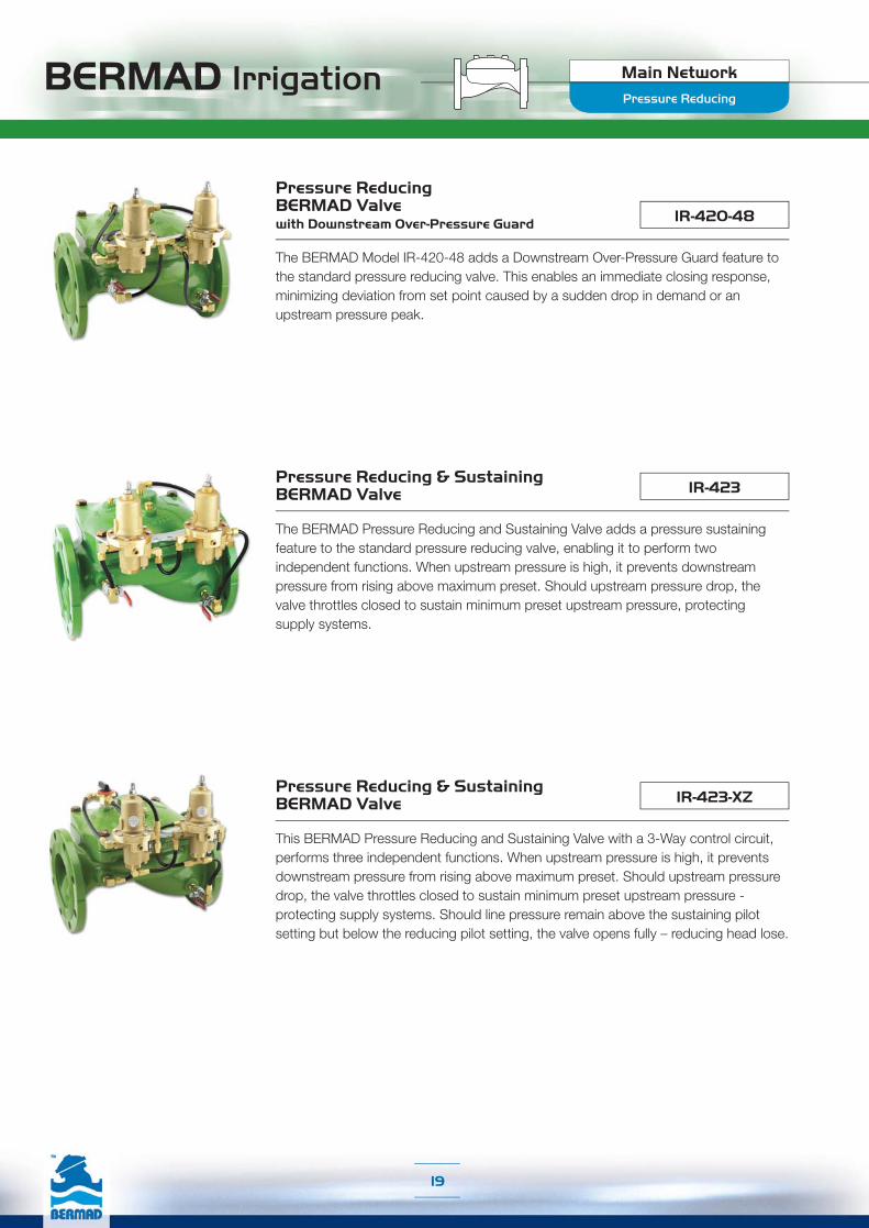
Pressure Reducing
IR-420-48
Pressure Reducing BERMAD Valve with Downstream Over-Pressure Guard
The BERMAD Model IR-420-48 adds a Downstream Over-Pressure Guard feature to the standard pressure reducing valve. This enables an immediate closing response, minimizing deviation from set point caused by a sudden drop in demand or an upstream pressure peak.
IR-423Pressure Reducing & Sustaining BERMAD Valve
The BERMAD Pressure Reducing and Sustaining Valve adds a pressure sustaining feature to the standard pressure reducing valve, enabling it to perform two independent functions. When upstream pressure is high, it prevents downstream pressure from rising above maximum preset. Should upstream pressure drop, the valve throttles closed to sustain minimum preset upstream pressure, protecting supply systems.
IR-423-XZPressure Reducing & Sustaining BERMAD Valve
This BERMAD Pressure Reducing and Sustaining Valve with a 3-Way control circuit, performs three independent functions. When upstream pressure is high, it prevents downstream pressure from rising above maximum preset. Should upstream pressure drop, the valve throttles closed to sustain minimum preset upstream pressure - protecting supply systems. Should line pressure remain above the sustaining pilot setting but below the reducing pilot setting, the valve opens fully – reducing head lose.

BERMAD Irrigation Main Network
20
IR-720-PDProportional Pressure Reducing BERMAD Valve
The BERMAD Proportional Pressure Reducing Valve is a pilot-less, double chambered, hydraulic control valve that reduces higher upstream pressure to lower downstream pressure at a fixed ratio.
WW-720-55
Pressure Reducing BERMAD Valve with Solenoid Control
The BERMAD Pressure Reducing Valve with Solenoid Control adds an On/Off control feature to the standard Pressure Reducing valve. It opens and shuts in response to an electric signal.
WW-723Pressure Reducing & Sustaining BERMAD Valve
The BERMAD Pressure Reducing and Sustaining Valve adds a pressure sustaining feature to the standard pressure reducing valve, enabling it to perform two independent functions. When upstream pressure is high, it prevents downstream pressure from rising above maximum preset. Should upstream pressure drop, the valve throttles closed to sustain minimum preset upstream pressure, protecting supply systems.
WW-720Pressure Reducing BERMAD Valve
The BERMAD Pressure Reducing Valve is a hydraulically operated, diaphragm actuated control valve that reduces higher upstream pressure to lower constant downstream pressure regardless of fluctuating demand or varying upstream pressure.
Pressure Reducing

BERMAD Irrigation Main Network
21
Applications Guide
■ Pressure Reducing Stations■ System Burst Protection■ Momentary Pressure Peak Elimination■ System Failure Visual Indication■ Filter Burst Protection
Pressure Relief ValvesSudden changes in demand - switching of irrigation Shifts, closing of reservoir valves, air release valve action, completion of line fill-up, and so on - create a high pressure wave, which travels along the line. Pressure Relief Valves, when carefully designed, selected, sized and positioned, are the most secure simple and cost-effective way of dealing with such problems. They relieve excessive system pressure by opening fully in response to a pressure rise, responding immediately, accurately, and with high repeatability.
Pressure Relief
BERMAD Irrigation Main Network
22
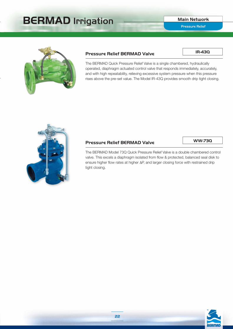
IR-43Q Pressure Relief BERMAD Valve
The BERMAD Quick Pressure Relief Valve is a single chambered, hydraulically operated, diaphragm actuated control valve that responds immediately, accurately, and with high repeatability, relieving excessive system pressure when this pressure rises above the pre-set value. The Model IR-43Q provides smooth drip tight closing.
WW-73QPressure Relief BERMAD Valve
The BERMAD Model 73Q Quick Pressure Relief Valve is a double chambered control valve. This excels a diaphragm isolated from flow & protected, balanced seal disk to ensure higher flow rates at higher ΔP, and larger closing force with restrained drip tight closing.
Pressure Relief
BERMAD Irrigation Main Network
23
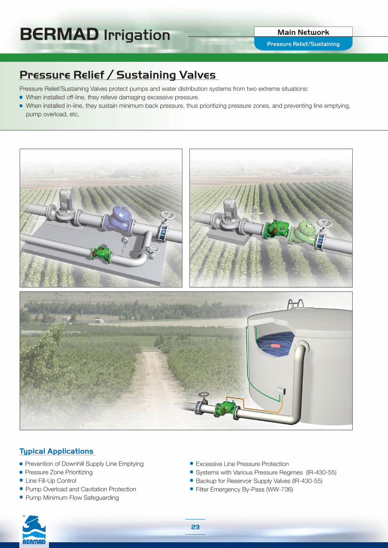
Typical Applications
■ Prevention of Downhill Supply Line Emptying ■ Pressure Zone Prioritizing■ Line Fill-Up Control■ Pump Overload and Cavitation Protection■ Pump Minimum Flow Safeguarding
■ Excessive Line Pressure Protection■ Systems with Various Pressure Regimes (IR-430-55)■ Backup for Reservoir Supply Valves (IR-430-55)■ Filter Emergency By-Pass (WW-736)
Pressure Relief / Sustaining Valves Pressure Relief/Sustaining Valves protect pumps and water distribution systems from two extreme situations:■ When installed off-line, they relieve damaging excessive pressure.■ When installed in-line, they sustain minimum back pressure, thus prioritizing pressure zones, and preventing line emptying, pump overload, etc.
Pressure Relief/Sustaining

BERMAD Irrigation Main Network
24
WW-736Differential Pressure Sustaining BERMAD Valve
The BERMAD Differential Pressure Sustaining Valve sustains minimum pre-set differential pressure between two points such as pump suction and discharge, filter inlet and outlet, heat exchanger or chiller distribution and collection lines, etc.
The BERMAD Pressure Sustaining Valve with Solenoid Control adds an On/Off control feature to the standard pressure sustaining valve. It opens and shuts in response to an electric signal, controlling systems with various pressure regimes or serving as backup for reservoir supply valves.
WW-730-55
Pressure Relief / Sustaining BERMAD Valve with Solenoid Control
IR-430-55
WW-730Pressure Relief / Sustaining BERMAD Valve
The BERMAD Pressure Relief/Sustaining Valve is a hydraulically operated, diaphragm actuated control valve that can fulfill either of two separate functions. When installed in-line, it sustains minimum preset upstream (back) pressure regardless of fluctuating flow or varying downstream pressure. When installed as a relief or circulation valve, it relieves line pressure in excess of preset value.
IR-430
Pressure Relief/Sustaining
Pressure Sustaining BERMAD Valve
This BERMAD Pressure Relief/Sustaining Valve with a 3-Way control circuit sustains minimum preset upstream (back) pressure regardless of fluctuating flow or varying downstream pressure. It opens fully upon line pressure rise above setting, saving system head loss & energy.
IR-430-XZ
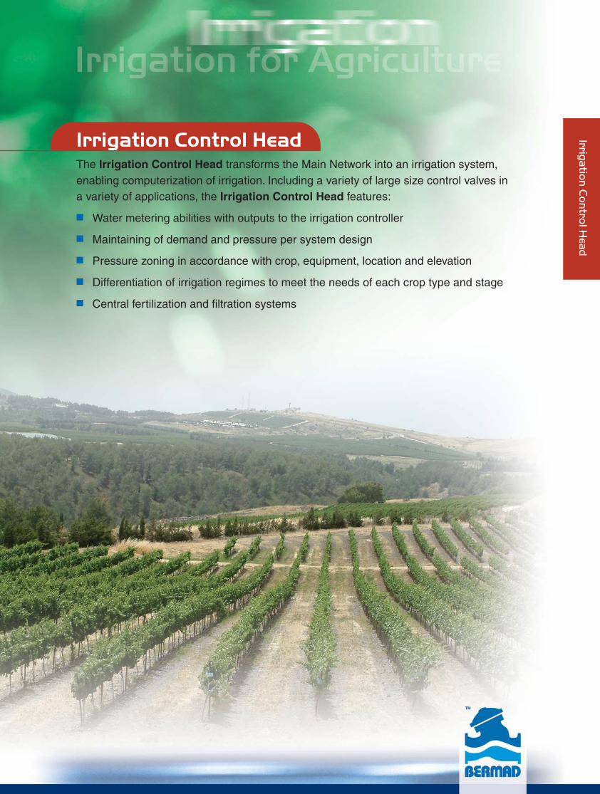
Irrigation Control HeadThe Irrigation Control Head transforms the Main Network into an irrigation system,enabling computerization of irrigation. Including a variety of large size control valves ina variety of applications, the Irrigation Control Head features:
■ Water metering abilities with outputs to the irrigation controller
■ Maintaining of demand and pressure per system design
■ Pressure zoning in accordance with crop, equipment, location and elevation
■ Differentiation of irrigation regimes to meet the needs of each crop type and stage
■ Central fertilization and filtration systems
Irriga
tion
Co
ntro
l Hea
d
BERMAD Irrigation
Irrigation Control Head
Irrigation Control Head
Irri
ga
tio
n C
on
tro
l Hea
d
27
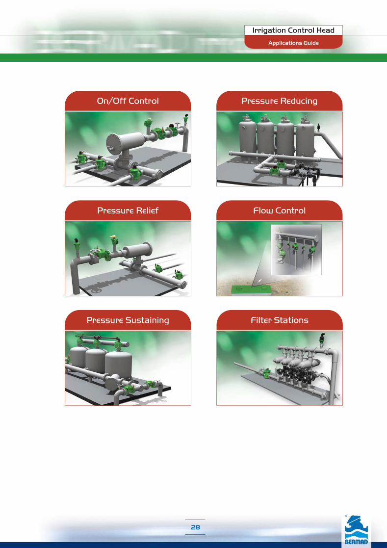
On/Off Control
Pressure Relief
Pressure Sustaining
Pressure Reducing
Flow Control
Filter Stations
Applications Guide
Irrigation Control Head
28
BERMAD Irrigation
29
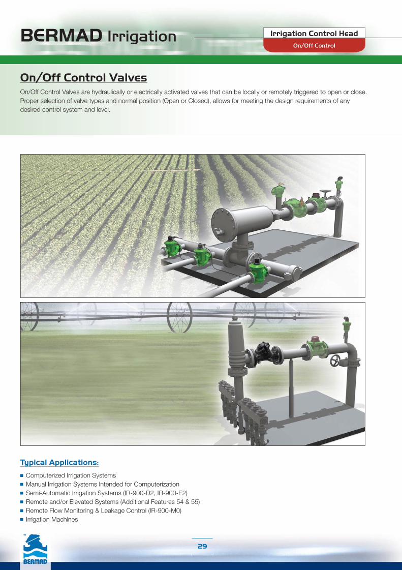
Typical Applications:
■ Computerized Irrigation Systems■ Manual Irrigation Systems Intended for Computerization■ Semi-Automatic Irrigation Systems (IR-900-D2, IR-900-E2)■ Remote and/or Elevated Systems (Additional Features 54 & 55)■ Remote Flow Monitoring & Leakage Control (IR-900-M0)■ Irrigation Machines
On/Off Control ValvesOn/Off Control Valves are hydraulically or electrically activated valves that can be locally or remotely triggered to open or close. Proper selection of valve types and normal position (Open or Closed), allows for meeting the design requirements of any desired control system and level.
On/Off Control
Irrigation Control Head

BERMAD Irrigation
30
IR-405-ZHydraulic Control BERMAD Valve
The BERMAD Hydraulic Control Valve is a hydraulically operated, diaphragm actuated control valve that opens and shuts off in response to a local or remote pressure command.
IR-410-X Solenoid Controlled BERMAD Valve
This Solenoid Controlled, line pressure driven, hydraulically operated valve opens or shuts in response to an electric signal. Its metal control accessories and circuit ensure a rigid, damage resistant main valve. The solenoid is compliant with common controllers on the market, and features a manual override.
IR-405-54-RXZ Hydraulic Control BERMAD Valve, Normally Closed with Hydraulic Relay
This Normally Closed, line pressure driven, hydraulic control valve opens in response to an external hydraulic pressure rise command and shuts in the absence of that command. Its metal control accessories and circuit ensure a rigid, damage resistant main valve.
On/Off Control
Irrigation Control Head

BERMAD Irrigation
31
IR-105-Z Hydraulic Control BERMAD Valve
The BERMAD Hydraulic Control Valve is a hydraulically operated, diaphragm actuated control valve that opens and shuts off in response to a local or remote pressure command.
IR-105-54-XHydraulic Control BERMAD Valve, Normally Closed with Hydraulic Relay
This Normally Closed, line pressure driven, hydraulic control valve opens in response to an external hydraulic pressure rise command and shuts in the absence of that command.
IR-110-XSolenoid Controlled BERMAD Valve
This Solenoid Controlled, line pressure driven, hydraulically operated valve, opens or shuts in response to an electric signal. The solenoid is compliant with common controllers on the market and it features a manual override.
On/Off Control
Irrigation Control Head

BERMAD Irrigation
32
IR-900-M0-ZHydrometer BERMAD with Magnetic Drive
The BERMAD Hydrometer with Magnetic Drive integrates a vertical turbine Woltman-type water meter with a diaphragm actuated hydraulic control valve. The impeller drive is magnetically coupled to a vacuum-sealed meter register in the control head. As the system's flow meter and main valve.The Hydrometer controls system irrigation together with the irrigation controller. It opens and shuts in response to a local or remote pressure command.
IR-900-M0-54-RXZ
Hydrometer BERMAD Magnetic Drive, Normally Closed with Hydraulic Relay
This Normally Closed, line pressure driven Hydrometer with Magnetic Drive opens in response to an external hydraulic pressure rise command and shuts in the absence of that command. Its metal control accessories and circuit ensure a rigid, damage resistant hydrometer.
IR-910-M0-RXHydrometer BERMAD, Magnetic Drive with Solenoid Control
This Solenoid Controlled, line pressure driven Hydrometer with Magnetic Drive, opens or shuts in response to an electric signal. The solenoid is compliant with common controllers on the market and features a manual override.
IR-900-D2Automatic Metering Valve (AMV) BERMAD
The BERMAD Automatic Metering Valve integrates a vertical turbine Woltman-type water meter with a diaphragm actuated hydraulic control valve. Equipped with a Mechanical Shut-Off Pilot, the BERMAD IR-900-D2 enables volumetric irrigation in non-computerized systems. It automatically shuts itself off after accurately delivering a manually preset quantity of water.
IR-900-E2Automatic Metering Valve (AMV) BERMAD for Sequential Irrigation
This BERMAD Automatic Metering Valve is equipped with a mechanical sequential shut-off pilot. When open, it transmutes pressure to the Next AMV, closing it. When the AMV shuts itself, it allows the next AMV to open and deliver a manually preset quantity of water.Working in a group of manually preset AMV's connected to each other by a control tube and operating in sequence, it enables semi-automatic irrigation in non-computerized systems.
On/Off Control
Irrigation Control Head

Pressure Reducing Valve for Drip-Tape ApplicationsThe unique low pressure requirements and laterals sensitivity in Drip-Tape projects, dictate special care to the selection and functioning of its Pressure Reducing Valves. Equipped with Servo Pilot, BERMAD Pressure Reducing Valve for Drip-Tape Applications provide very low set point (0.5 bar; 7 psi) and a dynamic integrated needle valve resulting in very low hysteresis.
BERMAD Irrigation
33
Pressure Reducing Control ValvesThe transformation from the main network into the irrigation system often requires bridging of significant differences in pressure ratings and flow characteristics. Pressure Reducing Valves help accomplish this by reducing high and fluctuating inlet pressure to a lower constant predetermined delivery pressure. They maintain pressure per system design and help to form pressure zones in accordance with crop, equipment, location, elevation and irrigation regimes.
Typical Applications:
■ Pressure Reducing Systems■ Distribution Centers■ Computerized Irrigation Systems■ Manual Irrigation Systems Intended for Computerization■ Semi-Automatic Irrigation Systems (IR-920-D2)■ Remote Flow Monitoring & Leakage Control (IR-920-M0)■ Remote and/or Elevated Systems (Additional Features 54 & 55)■ Irrigation Machines■ Greenhouse irrigation centers
Pressure Reducing
Irrigation Control Head

BERMAD Irrigation
34
Pressure Reducing
Irrigation Control Head
IR-420-RXPressure Reducing BERMAD Valve
The BERMAD Pressure Reducing Valve is a line pressure driven control valve that reduces higher upstream pressure to lower constant downstream pressure regardless of fluctuating demand or varying upstream pressure. Its metal control accessories and circuit ensure a rigid, damage resistant valve.The Model IR-420-RX automatically opens fully upon pressure drop below setting.
IR-420-R
IR-420-50-RX Pressure Reducing BERMAD Valvewith Hydraulic Control
This Normally Open, line pressure driven Pressure Reducing Valve shuts in response to an external hydraulic pressure rise command. Its metal control accessories and circuit ensure a rigid, damage resistant main valve.The Model IR-420-50-RX automatically opens fully upon pressure drop below setting.
IR-420-50-R
IR-420-54-RXPressure Reducing BERMAD Valve, Normally Closed with Hydraulic Relay
This Normally Closed, line pressure driven Pressure Reducing Valve opens in response to an external hydraulic pressure rise command and shuts in the absence of that command. Its metal control accessories and circuit ensure a rigid, damage resistant main valve.The Model IR-420-54-RX automatically opens fully upon pressure drop below setting.
IR-420-54-R
IR-420-55-RXPressure Reducing BERMAD Valvewith Solenoid Control
This Solenoid Controlled, line pressure driven Pressure Reducing Valve opens or shuts in response to an electric signal. Its metal control accessories and circuit ensure a rigid, damage resistant main valve. The solenoid is compliant with common controllers on the market.The Model IR-420-55-RX automatically opens fully upon pressure drop below setting.
IR-420-55-R
IR-420-R
IR-420-50-R
IR-420-54-R
IR-420-55-R
BERMAD Irrigation
35
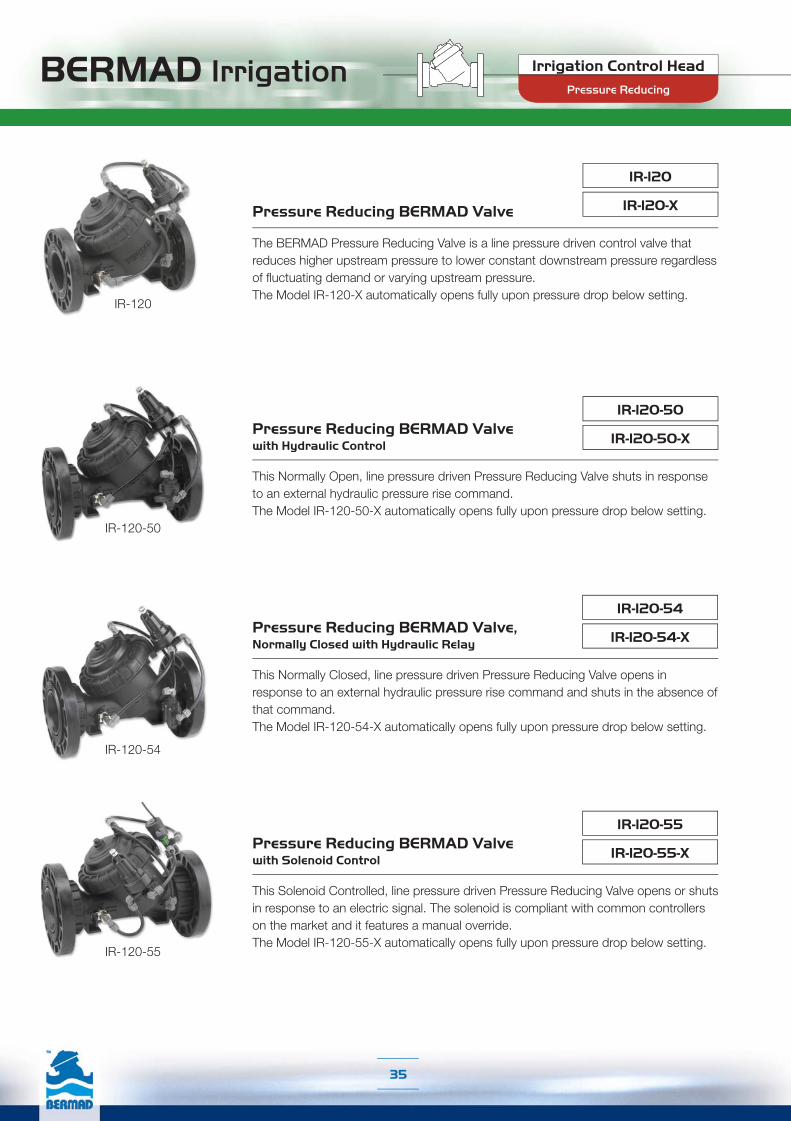
IR-120-XPressure Reducing BERMAD Valve
The BERMAD Pressure Reducing Valve is a line pressure driven control valve that reduces higher upstream pressure to lower constant downstream pressure regardless of fluctuating demand or varying upstream pressure.The Model IR-120-X automatically opens fully upon pressure drop below setting.
Irrigation Control Head
Pressure Reducing
IR-120
IR-120-50-X Pressure Reducing BERMAD Valvewith Hydraulic Control
This Normally Open, line pressure driven Pressure Reducing Valve shuts in response to an external hydraulic pressure rise command.The Model IR-120-50-X automatically opens fully upon pressure drop below setting.
IR-120-50
IR-120-54-XPressure Reducing BERMAD Valve, Normally Closed with Hydraulic Relay
This Normally Closed, line pressure driven Pressure Reducing Valve opens in response to an external hydraulic pressure rise command and shuts in the absence of that command.The Model IR-120-54-X automatically opens fully upon pressure drop below setting.
IR-120-54
Pressure Reducing BERMAD Valvewith Solenoid Control
This Solenoid Controlled, line pressure driven Pressure Reducing Valve opens or shuts in response to an electric signal. The solenoid is compliant with common controllers on the market and it features a manual override.The Model IR-120-55-X automatically opens fully upon pressure drop below setting.
IR-120-55-X
IR-120-55
IR-120
IR-120-50
IR-120-54
IR-120-55

BERMAD Irrigation
36
Pressure Reducing
Irrigation Control Head
IR-920-D2-RXPressure Reducing BERMAD Automatic Metering Valve (AMV)
The BERMAD Pressure Reducing Automatic Metering Valve integrates a vertical turbine Woltman-type water meter, with a diaphragm actuated hydraulic control valve. Equipped with a Shut-Off Pilot and a Pressure Reducing Pilot, the BERMAD IR-920-D2-R reduces higher upstream pressure to lower constant downstream pressure. It automatically shuts itself off after accurately delivering a preset quantity of water.The Model IR-920-D2-RX automatically opens fully upon pressure drop below setting.
IR-920-D2-R
IR-920-M0-55-RX Pressure Reducing BERMAD Hydrometer, Magnetic Drive with Solenoid Control
This Solenoid Controlled, Pressure Reducing Hydrometer opens or shuts in response to an electric signal. The solenoid is compliant with common controllers on the market. The Model IR-920-M0-55-RX automatically opens fully upon pressure drop below setting.
IR-920-M0-55-R
IR-920-M0-54-RX Pressure Reducing BERMAD Hydrometer, Magnetic Drive Normally Closed with Hydraulic Relay
This Normally Closed, Pressure Reducing Hydrometer opens in response to an external hydraulic pressure rise command and shuts in the absence of that command. The Model IR-920-M0-54-RX automatically opens fully upon pressure drop below setting.
IR-920-M0-54-R
IR-920-M0-50-RX Pressure Reducing BERMAD Hydrometer, Magnetic Drive with Hydraulic Control
This Normally Open, Pressure Reducing Hydrometer shuts in response to an external hydraulic pressure rise command. The Model IR-920-M0-50-RX automatically opens fully upon pressure drop below setting.
IR-920-M0-50-R
IR-920-M0-RX Pressure Reducing BERMAD Hydrometer, with Magnetic Drive
The BERMAD Pressure Reducing Hydrometer integrates a vertical turbine Woltman-type water meter, with a diaphragm actuated hydraulic control valve. It reduces higher upstream pressure to lower constant downstream pressure regardless of fluctuating demand or varying upstream pressure. Its metal control accessories and circuit provide a rigid, damage resistant valve.The Model IR-920-M0-RX automatically opens fully upon pressure drop below setting.
IR-920-M0-R
IR-920-M0-R
IR-920-M0-50-R
IR-920-M0-54-R
IR-920-M0-55-R
IR-920-D2-R
BERMAD Irrigation
37
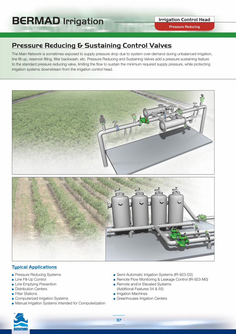
Pressure Reducing & Sustaining Control ValvesThe Main Network is sometimes exposed to supply pressure drop due to system over-demand during unbalanced irrigation, line fill-up, reservoir filling, filter backwash, etc. Pressure Reducing and Sustaining Valves add a pressure sustaining feature to the standard pressure reducing valve, limiting the flow to sustain the minimum required supply pressure, while protecting irrigation systems downstream from the irrigation control head.
Typical Applications
■ Pressure Reducing Systems■ Line Fill-Up Control■ Line Emptying Prevention■ Distribution Centers■ Filter Stations■ Computerized Irrigation Systems■ Manual Irrigation Systems Intended for Computerization
■ Semi-Automatic Irrigation Systems (IR-923-D2)■ Remote Flow Monitoring & Leakage Control (IR-923-M0)■ Remote and/or Elevated Systems
(Additional Features 54 & 55)■ Irrigation Machines■ Greenhouses Irrigation Centers
Pressure Reducing
Irrigation Control Head

BERMAD Irrigation
38
Pressure Reducing
Irrigation Control Head
The BERMAD Pressure Reducing and Sustaining Valve is a line pressure driven control valve that performs two independent functions. It sustains the preset minimum upstream pressure, and reduces downstream pressure to a constant preset maximum. The metal control accessories and circuit provide a rigid, damage resistant valve.The Model IR-423-RX automatically opens fully when line pressure is above sustaining pilot set-point and below reducing pilot set-point.
IR-423-RXPressure Reducing & Sustaining BERMAD Valve
IR-423-R
This Normally Open, line pressure driven Pressure Reducing and Sustaining Valve shuts in response to an external hydraulic pressure rise command. Its metal control accessories and circuit provide a rigid, damage resistant main valve.The Model IR-423-50-RX automatically opens fully when line pressure is above sustaining pilot set-point and below reducing pilot set-point.
Pressure Reducing & Sustaining BERMAD Valve with Hydraulic Control IR-423-50-RX
IR-423-50-R
This Solenoid Controlled, line pressure driven Pressure Reducing and Sustaining Valve opens or shuts in response to an electric signal. Its metal control accessories and circuit provide a rigid, damage resistant main valve. The solenoid is compliant with common controllers on the market.The Model IR-423-55-RX automatically opens fully when line pressure is above sustaining pilot set-point and below reducing pilot set-point.
Pressure Reducing & Sustaining BERMAD Valve with Solenoid Control IR-423-55-RX
IR-423-55-R
IR-423-R
IR-423-50-R
IR-423-55-R
BERMAD Irrigation
39
Pressure Reducing
Irrigation Control Head
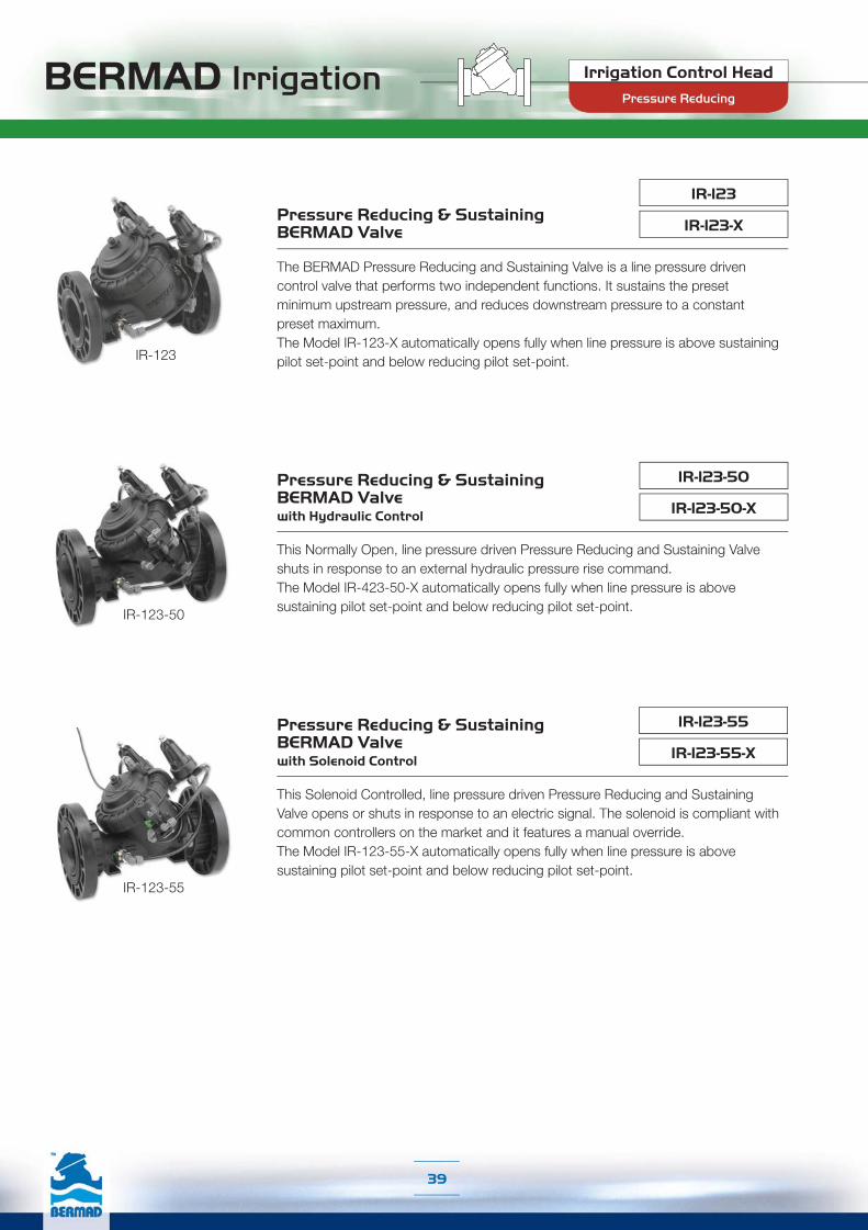
The BERMAD Pressure Reducing and Sustaining Valve is a line pressure driven control valve that performs two independent functions. It sustains the preset minimum upstream pressure, and reduces downstream pressure to a constant preset maximum.The Model IR-123-X automatically opens fully when line pressure is above sustaining pilot set-point and below reducing pilot set-point.
IR-123-XPressure Reducing & Sustaining BERMAD Valve
IR-123
This Normally Open, line pressure driven Pressure Reducing and Sustaining Valve shuts in response to an external hydraulic pressure rise command. The Model IR-423-50-X automatically opens fully when line pressure is above sustaining pilot set-point and below reducing pilot set-point.
Pressure Reducing & Sustaining BERMAD Valve with Hydraulic Control IR-123-50-X
IR-123-50
This Solenoid Controlled, line pressure driven Pressure Reducing and Sustaining Valve opens or shuts in response to an electric signal. The solenoid is compliant with common controllers on the market and it features a manual override.The Model IR-123-55-X automatically opens fully when line pressure is above sustaining pilot set-point and below reducing pilot set-point.
Pressure Reducing & Sustaining BERMAD Valve with Solenoid Control IR-123-55-X
IR-123-55
IR-123
IR-123-50
IR-123-55

BERMAD Irrigation
40
Pressure Reducing
Irrigation Control Head
The BERMAD Pressure Reducing and Sustaining Hydrometer integrates a vertical turbine Woltman-type water meter, with a diaphragm actuated hydraulic control valve. The impeller drive is magnetically coupled to a vacuum-sealed meter register in the control head. The Hydrometer performs two independent functions. It sustains the preset minimum upstream pressure, and reduces downstream pressure to a constant preset maximum. Its metal control accessories and circuit provide a rigid, damage resistant valve.The Model IR-923-M0-RX automatically opens fully when line pressure is above sustaining pilot set-point and below reducing pilot set-point.
Pressure Reducing & Sustaining BERMAD Hydrometer, Magnetic Drive IR-923-M0-RX
IR-923-M0-R
IR-923-M0-50-RX
Pressure Reducing & Sustaining BERMAD Hydrometer, Magnetic Drive with Hydraulic Control
This Normally Open, Pressure Reducing and Sustaining Hydrometer shuts in response to an external hydraulic pressure rise command. As the system's flow meter and main valve, it controls system irrigation together with the irrigation controller.The Model IR-923-M0-50-RX automatically opens fully when line pressure is above sustaining pilot set-point and below reducing pilot set-point.
IR-923-M0-50-R
Pressure Reducing & Sustaining BERMAD Hydrometer, Magnetic Drive with Solenoid Control
This Solenoid Controlled, Pressure Reducing and Sustaining Hydrometer opens or shuts in response to an electric signal. As the system’s flow meter and main valve, it controls system irrigation together with the irrigation controller. The solenoid is compliant with controllers on the market.The Model IR-923-M0-55-RX automatically opens fully when line pressure is above sustaining pilot set-point and below reducing pilot set-point.
IR-923-M0-55-RX
IR-923-M0-55-R
IR-923-D2-RXPressure Reducing & Sustaining BERMAD Automatic Metering Valve (AMV)
The BERMAD Pressure Reducing & Sustaining Automatic Metering Valve integrates a vertical turbine Woltman-type water meter, with a diaphragm actuated hydraulic control valve. The AMV performs three independent functions. It sustains the preset minimum upstream pressure, reduces downstream pressure to a constant preset maximum, and automatically shuts itself off after accurately delivering a preset quantity of water.The Model IR-923-D2-RX automatically opens fully when line pressure is above sustaining pilot set-point and below reducing pilot set-point.
IR-923-D2-R
IR-923-M0-R
IR-923-M0-50-R
IR-923-M0-55-R
IR-923-D2-R
BERMAD Irrigation
41
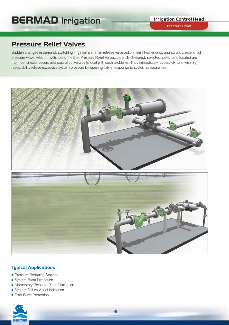
Pressure Relief Valves Sudden changes in demand, switching irrigation shifts, air release valve action, line fill-up ending, and so on, create a high pressure wave, which travels along the line. Pressure Relief Valves, carefully designed, selected, sized, and located are the most simple, secure and cost effective way to deal with such problems. They immediately, accurately, and with high repeatability relieve excessive system pressure by opening fully in response to system pressure rise.
Typical Applications
■ Pressure Reducing Stations■ System Burst Protection■ Momentary Pressure Peak Elimination■ System Failure Visual Indication■ Filter Burst Protection
Pressure Relief
Irrigation Control Head

BERMAD Irrigation
42
IR-43Q
The BERMAD Quick Pressure Relief Valve is a single chambered, hydraulically operated, diaphragm actuated control valve that immediately, accurately, and with high repeatability relieves excessive system pressure when this pressure rises above the pre-set value. The Model IR-43Q provides smooth drip tight closing.
Pressure Relief BERMAD Valve
This quick-acting pressure relief valve is an engineered plastic control valve. It excels in its high durability, chemical and cavitation resistance, hYflow ‘Y’ valve body with “look through” design providing ultra-high flow capacity, and unitized flexible diaphragm with a guided plug preventing diaphragm distortion.
Pressure Relief BERMAD Valve IR-13Q
Pressure Relief
Irrigation Control Head
BERMAD Irrigation
43
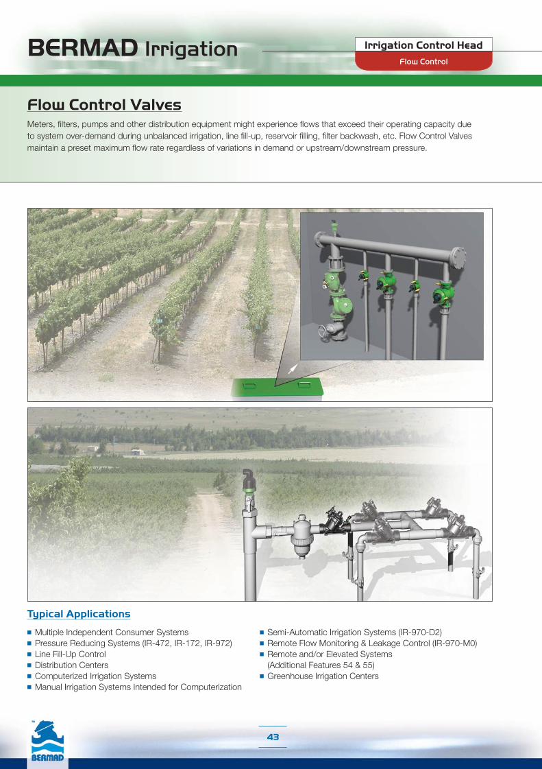
Flow Control ValvesMeters, filters, pumps and other distribution equipment might experience flows that exceed their operating capacity due to system over-demand during unbalanced irrigation, line fill-up, reservoir filling, filter backwash, etc. Flow Control Valves maintain a preset maximum flow rate regardless of variations in demand or upstream/downstream pressure.
Typical Applications
■ Multiple Independent Consumer Systems■ Pressure Reducing Systems (IR-472, IR-172, IR-972)■ Line Fill-Up Control■ Distribution Centers■ Computerized Irrigation Systems■ Manual Irrigation Systems Intended for Computerization
■ Semi-Automatic Irrigation Systems (IR-970-D2)■ Remote Flow Monitoring & Leakage Control (IR-970-M0)■ Remote and/or Elevated Systems
(Additional Features 54 & 55)■ Greenhouse Irrigation Centers
Flow Control
Irrigation Control Head
BERMAD Irrigation
44
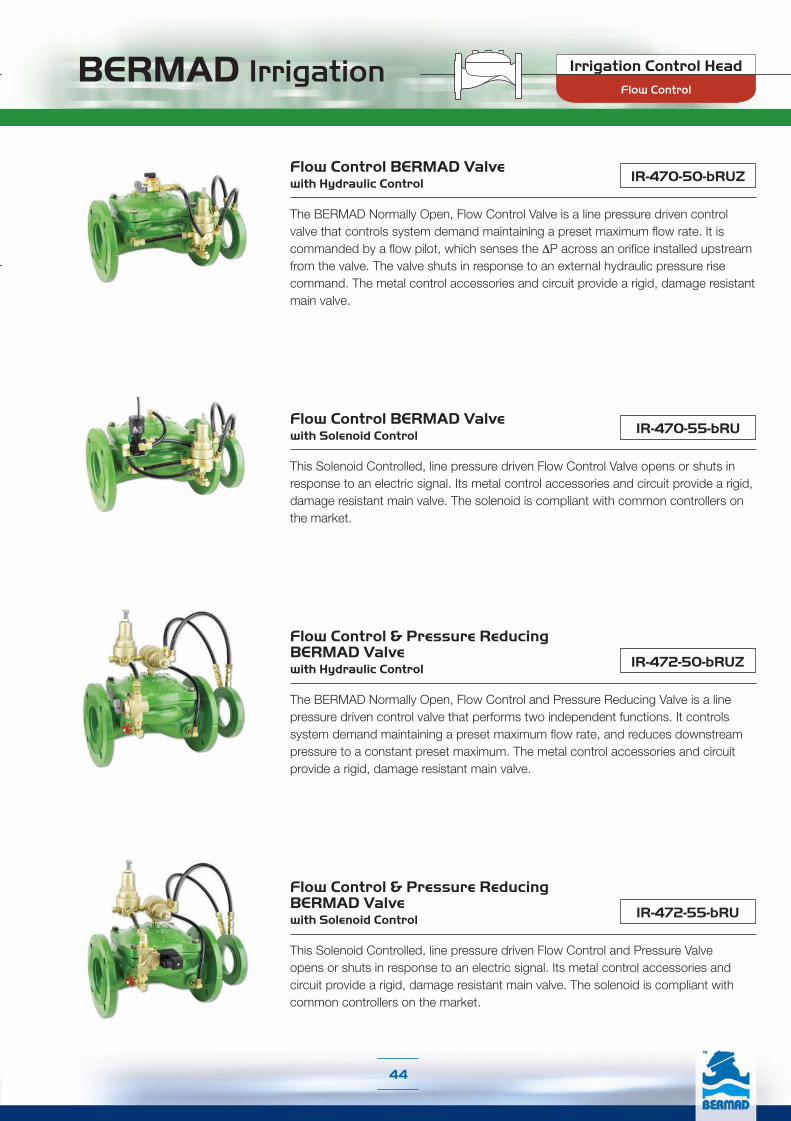
The BERMAD Normally Open, Flow Control Valve is a line pressure driven control valve that controls system demand maintaining a preset maximum flow rate. It is commanded by a flow pilot, which senses the ΔP across an orifice installed upstream from the valve. The valve shuts in response to an external hydraulic pressure rise command. The metal control accessories and circuit provide a rigid, damage resistant main valve.
Flow Control BERMAD Valve with Hydraulic Control IR-470-50-bRUZ
Flow Control BERMAD Valve with Solenoid Control IR-470-55-bRU
This Solenoid Controlled, line pressure driven Flow Control Valve opens or shuts in response to an electric signal. Its metal control accessories and circuit provide a rigid, damage resistant main valve. The solenoid is compliant with common controllers on the market.
Flow Control & Pressure Reducing BERMAD Valve with Hydraulic Control IR-472-50-bRUZ
The BERMAD Normally Open, Flow Control and Pressure Reducing Valve is a line pressure driven control valve that performs two independent functions. It controls system demand maintaining a preset maximum flow rate, and reduces downstream pressure to a constant preset maximum. The metal control accessories and circuit provide a rigid, damage resistant main valve.
Flow Control & Pressure Reducing BERMAD Valve with Solenoid Control
This Solenoid Controlled, line pressure driven Flow Control and Pressure Valve opens or shuts in response to an electric signal. Its metal control accessories and circuit provide a rigid, damage resistant main valve. The solenoid is compliant with common controllers on the market.
IR-472-55-bRU
Flow Control
Irrigation Control Head

BERMAD Irrigation Irrigation Control Head
45
The BERMAD Normally Open, Flow Control Valve is a line pressure driven control valve that controls system demand maintaining a preset maximum flow rate. It is commanded by a flow pilot, which senses the ΔP across a Differential Pressure Duct installed in the valve. The valve shuts in response to an external hydraulic pressure rise command.
Flow Control BERMAD Valve with Hydraulic Control IR-170-50-bDZ
Flow Control BERMAD Valve with Solenoid Control IR-170-55-bD
This Solenoid Controlled, line pressure driven Flow Control Valve opens or shuts in response to an electric signal. The solenoid is compliant with common controllers on the market and it features a manual override.
Flow Control & Pressure Reducing BERMAD Valve with Hydraulic Control IR-172-50-bDZ
The BERMAD Normally Open, Flow Control and Pressure Reducing Valve is a line pressure driven control valve that performs two independent functions. It controls system demand maintaining a preset maximum flow rate, and reduces downstream pressure to a constant preset maximum.
Flow Control & Pressure Reducing BERMAD Valve with Solenoid Control
This Solenoid Controlled, line pressure driven Flow Control and Pressure Valve opens or shuts in response to an electric signal. The solenoid is compliant with common controllers on the market and it features a manual override.
IR-172-55-bD
Flow Control

BERMAD Irrigation
46
The BERMAD Normally Open, Flow Control Hydrometer integrates a vertical turbine Woltman-type water meter, with a diaphragm actuated hydraulic control valve. The impeller drive is magnetically coupled to a vacuum-sealed meter register in the control head. The Hydrometer controls system demand maintaining a preset maximum flow rate. It is commanded by a paddle flow pilot, which includes a paddle that is positioned within the flow stream. As the system’s flow meter and main valve, it controls system irrigation together with the irrigation controller. It shuts in response to an external hydraulic pressure rise command.
Flow Control BERMAD Hydrometer, Magnetic Drive with Hydraulic Control IR-970-M0-50-RVZ
Flow Control BERMAD Hydrometer, Magnetic Drive with Solenoid Control IR-970-M0-55-RV
This Solenoid Controlled, line pressure driven Flow Control Hydrometer opens or shuts in response to an electric signal. As the system’s flow meter and main valve, it controls system irrigation together with the irrigation controller. The solenoid is compliant with common controllers on the market.
Flow Control & Pressure Reducing BERMAD Hydrometer, Magnetic Drive with Hydraulic Control IR-972-M0-50-RVZ
The BERMAD Normally Open, Flow Control and Pressure Reducing Hydrometer performs two independent functions. It controls system demand maintaining a preset maximum flow rate, and reduces downstream pressure to a constant preset maximum. As the system’s flow meter and main valve, it controls system irrigation together with the irrigation controller.
Flow Control & Pressure Reducing BERMAD Hydrometer, Magnetic Drive with Solenoid Control
This Solenoid Controlled, line pressure driven Flow Control and Pressure Reducing Hydrometer opens or shuts in response to an electric signal. As the system’s flow meter and main valve, it controls system irrigation together with the irrigation controller. The solenoid is compliant with common controllers on the market.
IR-972-M0-55-RV
Flow Control & Pressure Reducing BERMAD Automatic Metering Valve (AMV)
The BERMAD Flow Control and Pressure Reducing Automatic Metering Valve integrates a vertical turbine Woltman-type water meter, with a diaphragm actuated hydraulic control valve. The AMV performs three independent functions. It controls system demand maintaining a preset maximum flow rate, reduces downstream pressure to a constant preset maximum, and automatically shuts itself off after accurately delivering a preset quantity of water.
IR-972-D2-RV
Flow Control
Irrigation Control Head
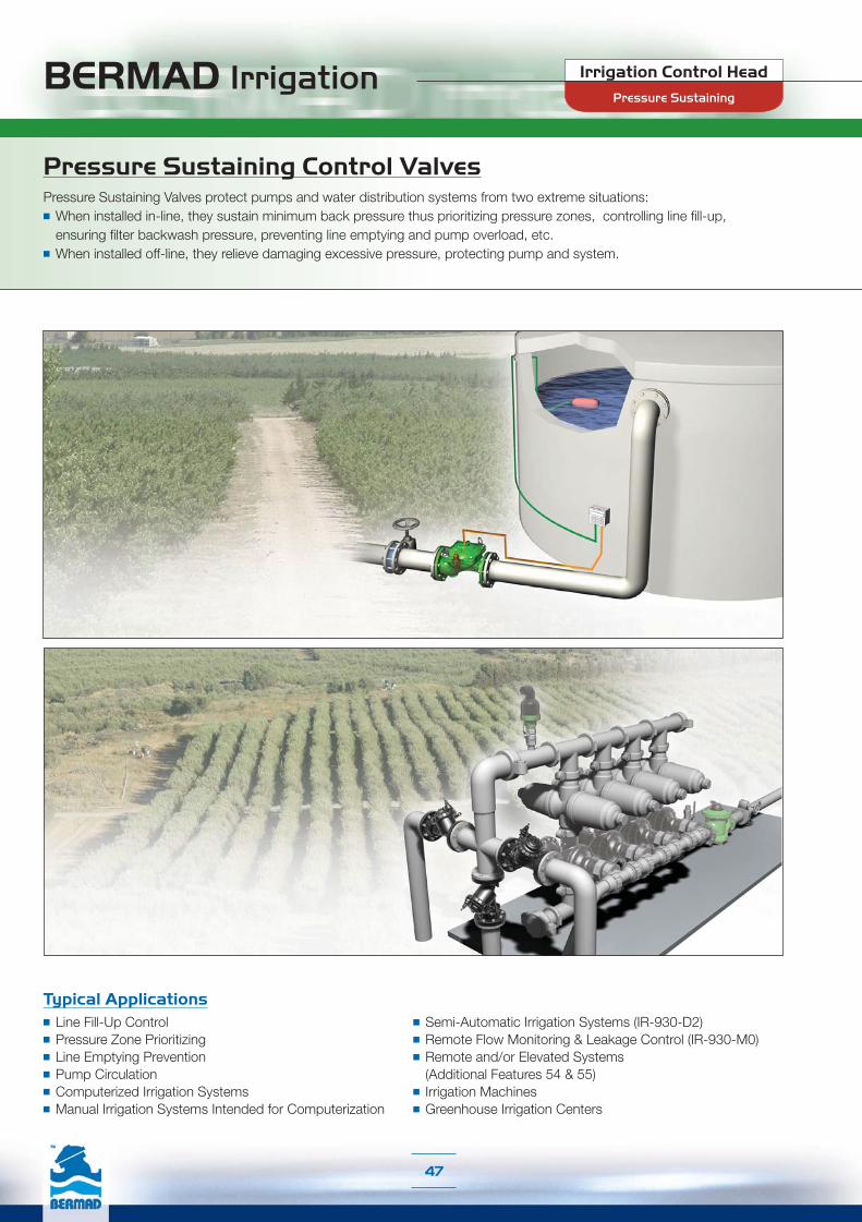
BERMAD Irrigation
47
Pressure Sustaining Control ValvesPressure Sustaining Valves protect pumps and water distribution systems from two extreme situations:■ When installed in-line, they sustain minimum back pressure thus prioritizing pressure zones, controlling line fill-up,
ensuring filter backwash pressure, preventing line emptying and pump overload, etc.■ When installed off-line, they relieve damaging excessive pressure, protecting pump and system.
Typical Applications■ Line Fill-Up Control■ Pressure Zone Prioritizing■ Line Emptying Prevention■ Pump Circulation■ Computerized Irrigation Systems■ Manual Irrigation Systems Intended for Computerization
■ Semi-Automatic Irrigation Systems (IR-930-D2)■ Remote Flow Monitoring & Leakage Control (IR-930-M0)■ Remote and/or Elevated Systems
(Additional Features 54 & 55)■ Irrigation Machines■ Greenhouse Irrigation Centers
Pressure Sustaining
Irrigation Control Head

BERMAD Irrigation
48
Pressure Sustaining
Irrigation Control Head
IR-430-50-RX Pressure Sustaining BERMAD Valve with Hydraulic Control
The BERMAD Normally Open, Pressure Sustaining Valve is a line pressure driven control valve that sustains minimum preset upstream (back) pressure regardless of fluctuating flow or varying downstream pressure. When installed offline, the BERMAD Model IR-430-50-R relieves line pressure in excess of preset. The valve shuts in response to an external hydraulic pressure rise command. The metal control accessories and circuit provide a rigid, damage resistant main valve.The Model IR-430-50-RX automatically opens fully when line pressure is in excess of setting.
IR-430-50-R
IR-430-55-RX
This Solenoid Controlled, line pressure driven Pressure Sustaining Valve opens or shuts in response to an electric signal. Its metal control accessories and circuit provide a rigid, damage resistant main valve. The solenoid is compliant with common controllers on the market.The Model IR-430-55-RX automatically opens fully when line pressure is in excess of setting.
Pressure Sustaining BERMAD Valve with Solenoid Control
IR-430-55-R
IR-430-50-R
IR-430-55-R

BERMAD Irrigation
49
IR-130-55-X
IR-130-50-X
The BERMAD Normally Open, Pressure Sustaining Valve is a line pressure driven control valve that sustains minimum preset upstream (back) pressure regardless of fluctuating flow or varying downstream pressure. When installed offline, the Model IR-130-50 relieves line pressure in excess of preset. The valve shuts in response to an external hydraulic pressure rise command.The Model IR-130-50-X automatically opens fully when line pressure is in excess of setting.
Pressure Sustaining BERMAD Valve with Hydraulic Control
Pressure Sustaining BERMAD Valve with Solenoid Control
This Solenoid Controlled, line pressure driven Pressure Sustaining Valve opens or shuts in response to an electric signal. The solenoid is compliant with common controllers on the market and it features a manual override.The Model IR-130-55-X automatically opens fully when line pressure is in excess of setting.
Pressure Sustaining
Irrigation Control Head
IR-130-50
IR-130-55
IR-130-50
IR-130-55
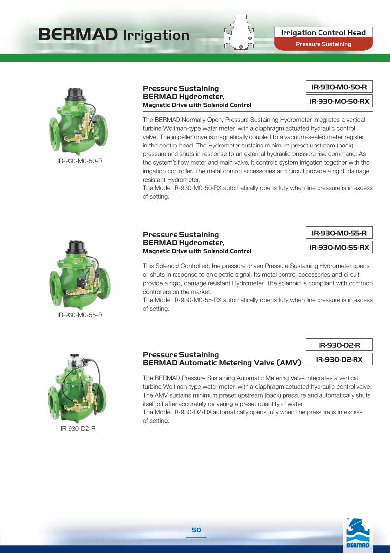
BERMAD Irrigation
50
Irrigation Control Head
Pressure Sustaining
IR-930-M0-50-RX
The BERMAD Normally Open, Pressure Sustaining Hydrometer integrates a vertical turbine Woltman-type water meter, with a diaphragm actuated hydraulic control valve. The impeller drive is magnetically coupled to a vacuum-sealed meter register in the control head. The Hydrometer sustains minimum preset upstream (back) pressure and shuts in response to an external hydraulic pressure rise command. As the system’s flow meter and main valve, it controls system irrigation together with the irrigation controller. The metal control accessories and circuit provide a rigid, damage resistant Hydrometer.The Model IR-930-M0-50-RX automatically opens fully when line pressure is in excess of setting.
Pressure Sustaining BERMAD Hydrometer, Magnetic Drive with Solenoid Control
IR-930-M0-50-R
IR-930-M0-55-RX
Pressure Sustaining BERMAD Hydrometer, Magnetic Drive with Solenoid Control
This Solenoid Controlled, line pressure driven Pressure Sustaining Hydrometer opens or shuts in response to an electric signal. Its metal control accessories and circuit provide a rigid, damage resistant Hydrometer. The solenoid is compliant with common controllers on the market.The Model IR-930-M0-55-RX automatically opens fully when line pressure is in excess of setting.
IR-930-M0-55-R
IR-930-D2-RXPressure Sustaining BERMAD Automatic Metering Valve (AMV)
The BERMAD Pressure Sustaining Automatic Metering Valve integrates a vertical turbine Woltman-type water meter, with a diaphragm actuated hydraulic control valve. The AMV sustains minimum preset upstream (back) pressure and automatically shuts itself off after accurately delivering a preset quantity of water.The Model IR-930-D2-RX automatically opens fully when line pressure is in excess of setting.
IR-930-D2-R
IR-930-M0-50-R
IR-930-M0-55-R
IR-930-D2-R

BERMAD Irrigation
51
Filter Station Control ValvesOne of the most common ways to clean sand, gravel, disk or strainer filter elements in filters used for the irrigation sector, is by backwashing them. Filter Backwash Valves close the inlet into the filter and divert filtered water to flow in the opposite direction through the filter element to the drain. The high flow velocity and ΔP create hydraulic forces which flush the filter-cake to the atmosphere, cleaning the filter element. Flow Control Valves limit the backwash flow to protect the filter element from excessive flow velocity and ΔP.
Typical Applications
■ Automatic Backwash of Filter Batteries❏ Gravel Filters❏ Sand Filters❏ Disk Filters❏ Screen Filters
■ Single Filter Autonomic Backwash System■ Angled or Straight Installations (IR-350 Series, Double Chamber Valves)■ Backwash Flow Limit (IR-470-beKU, IR-170-beU)
Filter Stations
Irrigation Control Head

BERMAD Irrigation
52
Filter Backwash Hydraulic BERMAD Valve, 3x3 Metal Body
This 3x3 Filter Backwash Hydraulic Valve features a metal body, providing rigid construction. It is available in Angle flow (A) and Straight flow (S) configurations.
IR-3x3-350-I
IR-2x2-350-RFilter Backwash Hydraulic BERMAD Valve, 2x2 Metal Body
This 2x2 Filter Backwash Hydraulic Valve features a metal body, providing rigid construction. It is available in Angle flow (A) and Straight flow (S) configurations.
Filter Backwash Hydraulic BERMAD Valve, 2x2 Plastic IR-2x2-350-P
The BERMAD Model IR-2x2-350-P is a compact 3-port valve, in a T configuration, constructed from reinforced plastic. It is a double chambered, hydraulically operated, and diaphragm actuated valve, designed for automatic backwashing of filters with 2" inlet and outlet ports. In response to a pressure rise command, its diaphragm actuated plug assembly closes the supply port drip tight, while opening the backwash port. The valve’s short travel guarantees smooth flow direction changes, conserves water supply, prevents filter site flooding, and eliminates mixing of supply and waste water. The BERMAD Model IR-2x2-350-P is available in Angle flow (A) and Straight flow (S) configurations.
Filter Backwash Hydraulic BERMAD Valve, 3x3 Plastic
This Double Chambered, Filter Backwash Hydraulic Valve suits filters with 3" Inlet and outlet Ports. It is available in Angle flow (A) and Straight flow (S) configurations.
IR-3x3-350-P
Filter Stations
Irrigation Control Head
Angle Flow Straight Flow
Angle Flow Straight Flow
Angle Flow Straight Flow
Angle Flow Straight Flow

BERMAD Irrigation
53
IR-4x3-350-A-I Filter Backwash Hydraulic BERMAD Valve, 4x3 Metal
The BERMAD Model IR-4x3-350-A-I is a compact 3-port valve, in a T configuration. It is a hydraulically operated and diaphragm actuated valve, designed for automatic backwashing of filters with 4" inlet and outlet ports. In response to a pressure rise command, its diaphragm actuated plug assembly closes the supply port drip tight, while opening the backwash port. The valve’s short travel guarantees smooth flow direction changes, conserves water supply, prevents filter site flooding, and eliminates mixing of supply and waste water. The valve’s metal construction ensures a rigid, damage resistant valve.
IR-4x4-350-A-I Filter Backwash Hydraulic BERMAD Valve, 4x4 Metal
This Filter Backwash Hydraulic Valve suits filters with 4" inlet and outlet ports and high backwash flow requirements.
Irrigation Control Head
Filter Stations

BERMAD Irrigation Irrigation Control Head
54
IR-470-beKU
The BERMAD Normally Open, Flow Control Valve is a line pressure driven control valve that controls filter backwash flow maintaining a preset maximum flow rate. It is commanded by a flow pilot, which senses the ΔP across an orifice installed upstream from the valve. The valve shuts in response to an external hydraulic pressure rise command.
Filter Backwash Flow Control BERMAD Valve
IR-170-beU Filter Backwash Flow ControlBERMAD Valve
This BERMAD Normally Open, Flow Control Valve is constructed of reinforced plastic.
Filter Stations

Infield Head-WorksLocated at the entrance from the supply network to the distribution lines and laterals,the Infield Head-Works serves as the system's final control of the water’s actual enterthe distribution lines. Including various types of electric or hydraulic on/off remote controlvalves, which combine a variety of features, the Infield Head-Works:
■ Controls irrigation shifts, applying water metering abilities with outputs to theirrigation controller
■ Maintains pre-designed system demand and pressure
■ Establishes pressure zones, protecting the distribution lines and the laterals
■ Differentiates irrigation regimes to meet changing crop stage
■ Incorporates local fertilization arrangements and final filtration solutions
Infield
Hea
d-W
orks
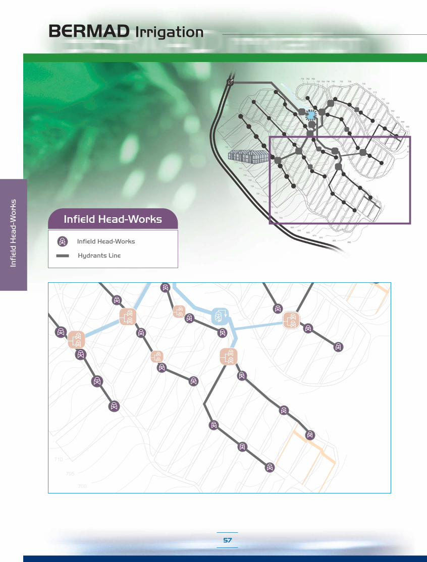
BERMAD Irrigation
Infield Head-Works
710
705
700
Infield Head-Works
Hydrants Line
Infi
eld
Hea
d-W
ork
s
57
710
705
700

Pressure Reducing, Standard
Pressure Reducing & Sustaining
Flow Control
On/Off Control
Pressure Reducing, Drip-Tape
Pressure Sustaining
Flow Control & Pressure Reducing
Applications Guide
Infield Head-Works
58

BERMAD Irrigation
59
Typical Applications:
■ Computerized Irrigation Systems■ Manual Irrigation Systems Intended for Computerization■ Semi-Automatic Irrigation Systems (IR-900-D0, IR-900-DD)■ Remote and/or Elevated Systems (Additional Features 54 & 55)■ Remote Flow Monitoring & Leakage Control (IR-900-M0)
On/Off Control ValvesOn/Off Control Valves are hydraulically or electrically activated valves that can be locally or remotely triggered to open or close. Proper selection of valve types and normal position (Open or Closed), ensures meeting the design requirements of every control system and level.
On/Off Control
Infield Head-Works

BERMAD Irrigation
60
IR-405-ZHydraulic Control BERMAD Valve
The BERMAD Hydraulic Control Valve is a hydraulically operated, diaphragm actuated control valve that opens and shuts off in response to a local or remote pressure command.
IR-410-KX Solenoid Controlled BERMAD Valve
This Solenoid Controlled, line pressure driven, hydraulically operated valve, opens or shuts in response to an electric signal. The solenoid is compliant with the common controllers on the market and it features a manual override.
IR-405-54-KX Hydraulic Control BERMAD Valve, Normally Closed with Hydraulic Relay
This Normally Closed, line pressure driven hydraulic control valve opens in response to an external hydraulic pressure rise command and shuts in the absence of that command.
On/Off Control
Infield Head-Works

BERMAD Irrigation
61
IR-105-Z Hydraulic Control BERMAD Valve
The BERMAD Hydraulic Control Valve is a hydraulically operated, diaphragm actuated control valve that opens and shuts off in response to a local or remote pressure command.
IR-105-54-XHydraulic Control BERMAD Valve, Normally Closed with Hydraulic Relay
This Normally Closed, line pressure driven, hydraulic control valve opens in response to an external hydraulic pressure rise command and shuts in the absence of that command.
IR-110-N1-2WSolenoid Controlled BERMAD Valve with 2-Way Internal Controls
This 2-Way Solenoid Controlled, line pressure driven, hydraulically operated valve includes an internal hydraulic Feed & Bleed control loop. The valve opens and closes drip-tight in response to an electric signal, which causes the solenoid to open or close the valve’s internal hydraulic loop. The solenoid is compliant with the common controllers on the market and it features a manual override.
On/Off Control
IR-110-XSolenoid Controlled BERMAD Valve
This Solenoid Controlled, line pressure driven, hydraulically operated valve, opens and closes drip-tight in response to an electric signal. The solenoid is compliant with the common controllers on the market and it features a manual override.
Infield Head-Works

BERMAD Irrigation
62
IR-900-M0-ZHydrometer BERMAD with Magnetic Drive
The BERMAD Hydrometer with Magnetic Drive integrates a vertical turbine Woltman-type water meter with a diaphragm actuated hydraulic control valve. The impeller drive is magnetically coupled to a vacuum-sealed meter register in the control head. Serving as Flow Meter and Main Valve, it controls system irrigation together with the irrigation controller. The Hydrometer opens and shuts in response to a local or remote pressure command.
IR-900-M0-54-KX
Hydrometer BERMAD Magnetic Drive, Normally Closed with Hydraulic Relay
This Normally Closed, line pressure driven Hydrometer with Magnetic Drive opens in response to an external hydraulic pressure rise command and shuts in the absence of that command.
IR-910-KXHydrometer BERMAD, Magnetic Drive with Solenoid Control
This Solenoid Controlled, line pressure driven Hydrometer with Magnetic Drive, opens or shuts in response to an electric signal. The solenoid is compliant with the common controllers on the market and it features a manual override.
IR-900-D0Automatic Metering Valve (AMV) BERMAD
The BERMAD Automatic Metering Valve integrates a vertical turbine Woltman-type water meter with a diaphragm actuated hydraulic control valve. Equipped with a Mechanical Shut-Off Pilot, the BERMAD IR-900-D0 enables volumetric irrigation in non-computerized systems. It automatically shuts itself off after accurately delivering a manually preset quantity of water.
IR-900-DDAutomatic Metering Valve (AMV) BERMAD for Sequential Irrigation
This BERMAD Automatic Metering Valve is equipped with a mechanical sequential shut-off pilot. When open it transmutes pressure to the Next AMV, closing it. When the AMV shuts itself, it allows the next AMV to open and deliver a manually preset quantity of water.Working in a group of manually preset AMV's connected to each other by a control tube and operating in sequence, it enables semi-automatic irrigation in non-computerized systems.
On/Off Control
Infield Head-Works
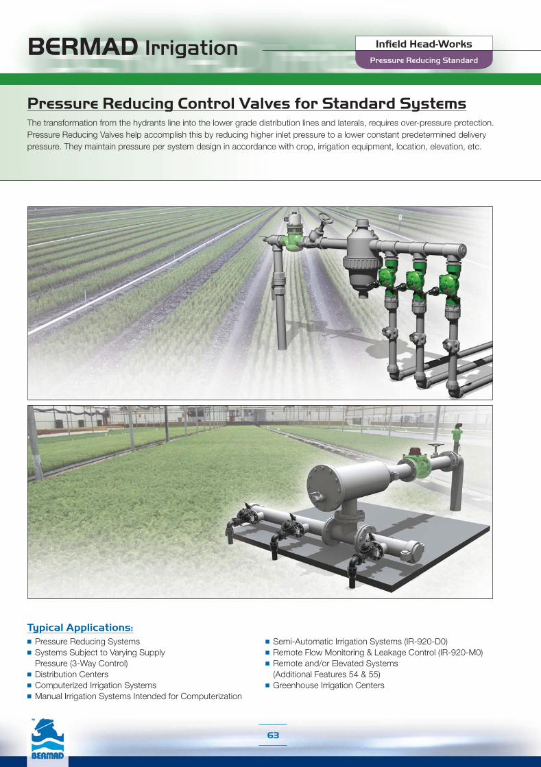
BERMAD Irrigation
63
Typical Applications:■ Pressure Reducing Systems■ Systems Subject to Varying Supply Pressure (3-Way Control)■ Distribution Centers■ Computerized Irrigation Systems■ Manual Irrigation Systems Intended for Computerization
■ Semi-Automatic Irrigation Systems (IR-920-D0)■ Remote Flow Monitoring & Leakage Control (IR-920-M0)■ Remote and/or Elevated Systems
(Additional Features 54 & 55)■ Greenhouse Irrigation Centers
Pressure Reducing Control Valves for Standard SystemsThe transformation from the hydrants line into the lower grade distribution lines and laterals, requires over-pressure protection. Pressure Reducing Valves help accomplish this by reducing higher inlet pressure to a lower constant predetermined delivery pressure. They maintain pressure per system design in accordance with crop, irrigation equipment, location, elevation, etc.
Pressure Reducing Standard
Infield Head-Works

BERMAD Irrigation
64
The BERMAD Pressure Reducing Valve is a line pressure driven control valve that reduces higher upstream pressure to lower preset downstream pressure. The valve automatically opens fully upon pressure drop below setting. Its advanced globe, hydro-efficient design and fully supported and balanced diaphragm ensure an unobstructed flow path, excellent low-flow regulation performance, and trouble-free, long life operation. The Model IR-420-RXZ includes Metal Accessories.
Pressure Reducing BERMAD Valve IR-420-RXZ
IR-420-KXZ
Pressure Reducing BERMAD Valvewith Hydraulic Control
This Normally Open, line pressure driven Pressure Reducing Valve shuts in response to an external hydraulic pressure rise command. The Model IR-420-50-RXZ includes Metal Accessories.
IR-420-50-RXZ
IR-420-50-KXZ
Pressure Reducing Standard
IR-420-54-3Q-KX
This Normally Closed, line pressure driven Pressure Reducing Valve opens in response to an external hydraulic pressure rise command, and shuts in the absence of that command. The model IR-420-54-3Q-KX Pressure Relief Override feature enables it to serve also as a Pressure Relief Valve, protecting the system even when in closed position.
Pressure Reducing BERMAD Valve, Normally Closed with Relief Override
IR-420-54-KX
Pressure Reducing BERMAD Valve, Normally Closed with Hydraulic Relay
IR-420-55-3Q-KX
IR-420-55-KX
Pressure Reducing BERMAD Valvewith Solenoid Control
This Solenoid Controlled, line pressure driven Pressure Reducing Valve opens or shuts in response to an electric signal. The solenoid is compliant with the common controllers on the market and it features a manual override. The model IR-420-55-3Q-KX Pressure Relief Override feature enables it to serve also as a Pressure Relief Valve, protecting the system even when in closed position.
Pressure Reducing BERMAD ValveSolenoid Controlied with Relief Override
IR-420-54-KX IR-420-54-3Q-KX
IR-420-55-KX IR-420-55-3Q-KX
Infield Head-Works
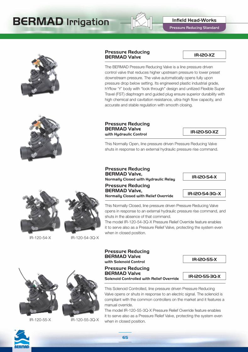
BERMAD Irrigation
65
IR-120-XZPressure Reducing BERMAD Valve
The BERMAD Pressure Reducing Valve is a line pressure driven control valve that reduces higher upstream pressure to lower preset downstream pressure. The valve automatically opens fully upon pressure drop below setting. Its engineered plastic industrial grade, hYflow ‘Y’ body with “look through” design and unitized Flexible Super Travel (FST) diaphragm and guided plug ensure superior durability with high chemical and cavitation resistance, ultra-high flow capacity, and accurate and stable regulation with smooth closing.
IR-120-50-XZ
Pressure Reducing BERMAD Valvewith Hydraulic Control
This Normally Open, line pressure driven Pressure Reducing Valve shuts in response to an external hydraulic pressure rise command.
IR-120-55-3Q-X
IR-120-55-X
Pressure Reducing BERMAD ValveSolenoid Controlled with Relief Override
This Solenoid Controlled, line pressure driven Pressure Reducing Valve opens or shuts in response to an electric signal. The solenoid is compliant with the common controllers on the market and it features a manual override. The model IR-120-55-3Q-X Pressure Relief Override feature enables it to serve also as a Pressure Relief Valve, protecting the system even when in closed position.
Pressure Reducing Standard
IR-120-54-3Q--X
IR-120-54-X
This Normally Closed, line pressure driven Pressure Reducing Valve opens in response to an external hydraulic pressure rise command, and shuts in the absence of that command. The model IR-120-54-3Q-X Pressure Relief Override feature enables it to serve also as a Pressure Relief Valve, protecting the system even when in closed position.
Pressure Reducing BERMAD Valve, Normally Closed with Relief Override
Pressure Reducing BERMAD Valve, Normally Closed with Hydraulic Relay
Pressure Reducing BERMAD Valvewith Solenoid Control
IR-120-54-X IR-120-54-3Q-X
IR-120-55-X IR-120-55-3Q-X
Infield Head-Works

BERMAD Irrigation
66
The BERMAD Pressure Reducing Hydrometer integrates a vertical turbine Woltman-type water meter with a diaphragm actuated hydraulic control valve. Serving as Flow Meter and Main Valve, it controls irrigation together with the irrigation controller reducing higher upstream pressure to lower preset downstream pressure. The hydrometer automatically opens fully upon pressure drop below setting. The Model IR-920-M0-RXZ includes Metal Accessories.
Pressure Reducing BERMAD Hydrometer, Magnetic Drive IR-920-M0-RXZ
IR-920-M0-KXZ
Pressure Reducing BERMAD Hydrometer, Magnetic Drive with Hydraulic Control
This Normally Open, line pressure driven Pressure Reducing Hydrometer shuts in response to an external hydraulic pressure rise command. The Model IR-920-M0-50-RXZ includes Metal Accessories.
IR-920-M0-50-RXZ
IR-920-M0-50-KXZ
IR-920-M0-54-KX
This Normally Closed, line pressure driven Pressure Reducing Hydrometer opens in response to an external hydraulic pressure rise command and shuts in the absence of that command.
Pressure Reducing BERMAD Hydrometer, Magnetic Drive, Normally Closed with Hydraulic Relay
Pressure Reducing BERMAD Automatic Metering Valve (AMV)
The BERMAD Pressure Reducing AMV integrates a vertical turbine Woltman-type water meter with a diaphragm actuated hydraulic control valve. Equipped with a Mechanical Shut-Off Pilot and a Pressure Reducing 3-Way Pilot, it reduces higher upstream pressure to lower preset downstream pressure, opens fully upon pressure drop below setting, and automatically shuts itself off after accurately delivering a manually preset quantity of water.
IR-920-D0-KX
IR-920-M0-55-KX
This Solenoid Controlled, line pressure driven Pressure Reducing Hydrometer opens or shuts in response to an electric signal. The solenoid is compliant with the common controllers on the market and it features a manual override.
Pressure Reducing BERMAD Hydrometer, Magnetic Drive with Solenoid Control
Pressure Reducing Standard
Infield Head-Works

BERMAD Irrigation
67
Typical Applications:■ Drip-Tape Systems■ Non-Compensated Drip Lines■ Low Set Pressure Applications■ Pressure Reducing Systems■ Systems Subject to Varying Supply Pressure
■ Computerized Irrigation Systems■ Manual Irrigation Systems Intended for Computerization■ Semi-Automatic Irrigation Systems (IR-920-D0)■ Remote Flow Monitoring & Leakage Control (IR-920-M0)■ Remote and/or Elevated Systems
(Additional Features 54 & 55)
Pressure Reducing Valves for Drip-Tape ApplicationsThe unique low pressure requirements and sensitivity of laterals in Drip-Tape projects demand special care in the selection and functioning of Pressure Reducing Valves. Equipped with Servo Pilot, BERMAD Pressure Reducing Valves for Drip-Tape Applications provide a very low set point (0.5 bar; 7 psi) and a dynamic integrated needle valve resulting in very high accuracy and pressure repeatability.
Pressure Reducing Drip-Tape
Infield Head-Works

BERMAD Irrigation
68
The BERMAD Pressure Reducing Valve is a line pressure driven control valve that reduces higher upstream pressure to very low and stable preset downstream pressure. Its advanced globe hydro-efficient design, and fully supported and balanced diaphragm, ensure an unobstructed flow path, excellent low-flow regulation performance, and trouble-free long life operation. The Model IR-420-bRZ includes Metal Accessories.
Pressure Reducing BERMAD Valve For Drip-Tape Applications IR-420-bRZ
IR-420-bKZ
Pressure Reducing BERMAD Valve with Hydraulic Control For Drip-Tape Applications
This Normally Open, line pressure driven Pressure Reducing Valve shuts in response to an external hydraulic pressure rise command. The Model IR-420-50-bRZ includes Metal Accessories.
IR-420-50-bRZ
IR-420-50-bKZ
IR-420-55-3Q-bK
IR-420-55-bK
Pressure Reducing BERMAD ValveSolenoid Controlied with Relief Override For Drip-Tape Applications
This Solenoid Controlled, line pressure driven Pressure Reducing Valve opens or shuts in response to an electric signal. The solenoid is compliant with the common controllers on the market and it features a manual override. The model IR-420-55-3Q-bK Pressure Relief Override feature enables it to serve also as a Pressure Relief Valve, protecting the system even when in closed position.
Pressure Reducing Drip-Tape
IR-420-54-3Q-bK
IR-420-54-bK
This Normally Closed, line pressure driven Pressure Reducing Valve opens in response to an external hydraulic pressure rise command, and shuts in the absence of that command. The model IR-420-54-3Q-bK Pressure Relief Override feature enables it to serve also as a Pressure Relief Valve, protecting the system even when in closed position.
Pressure Reducing BERMAD Valve, Normally Closed with Relief OverrideFor Drip-Tape Applications
Pressure Reducing BERMAD Valve, Normally Closed with Hydraulic RelayFor Drip-Tape Applications
Pressure Reducing BERMAD Valvewith Solenoid ControlFor Drip-Tape Applications
IR-420-55-bX IR-420-55-3Q-bX
IR-420-54-bX IR-420-54-3Q-bX
Infield Head-Works

BERMAD Irrigation
69
IR-120-bZ
Pressure Reducing BERMAD Valve For Drip-Tape Applications
The BERMAD Pressure Reducing Valve is a line pressure driven control valve that reduces higher upstream pressure to very low and stable preset downstream pressure. Its engineered plastic industrial grade, hYflow ‘Y’ body with “look through” design and unitized Flexible Super Travel (FST) diaphragm and guided plug excels in its highly durable chemical and cavitation resistance, ultra-high flow capacity, and accurate and stable regulation with smooth closing.
IR-120-50-bZ
Pressure Reducing BERMAD Valvewith Hydraulic Control For Drip-Tape Applications
This Normally Open, line pressure driven Pressure Reducing Valve shuts in response to an external hydraulic pressure rise command.
Pressure Reducing Drip-Tape
IR-120-54-3Q--b
IR-120-54-b
This Normally Closed, line pressure driven Pressure Reducing Valve opens in response to an external hydraulic pressure rise command, and shuts in the absence of that command. The model IR-120-54-3Q-b Pressure Relief Override feature enables it to serve also as a Pressure Relief Valve, protecting the system even when in closed position.
Pressure Reducing BERMAD Valve, Normally Closed with Relief OverrideFor Drip-Tape Applications
Pressure Reducing BERMAD Valve, Normally Closed with Hydraulic RelayFor Drip-Tape Applications
IR-120-55-3Q-b
IR-120-55-b
Pressure Reducing BERMAD ValveSolenoid Controlied with Relief Override For Drip-Tape Applications
This Solenoid Controlled, line pressure driven Pressure Reducing Valve opens or shuts in response to an electric signal. The solenoid is compliant with the common controllers on the market and it features a manual override. The model IR-120-55-3Q-b Pressure Relief Override feature enables it to serve also as a Pressure Relief Valve, protecting the system even when in closed position.
Pressure Reducing BERMAD Valvewith Solenoid ControlFor Drip-Tape Applications
IR-120-54-b IR-120-54-3Q-b
IR-120-55-b IR-120-55-3Q-b
Infield Head-Works

BERMAD Irrigation
70
The BERMAD Pressure Reducing Hydrometer integrates a vertical turbine Woltman-type water meter with a diaphragm actuated hydraulic control valve. Serving as Flow Meter and Main Valve, it controls irrigation together with the irrigation controller, reducing higher upstream pressure to very low and stable preset downstream pressure.The Model IR-920-M0-bRZ includes Metal Accessories.
Pressure Reducing BERMAD Hydrometer, Magnetic Drive For Drip-Tape Applications IR-920-M0-bRZ
IR-920-M0-bKZ
Pressure Reducing BERMAD Hydrometer, Magnetic Drive with Hydraulic ControlFor Drip-Tape Applications
This Normally Open, line pressure driven Pressure Reducing Hydrometer shuts in response to an external hydraulic pressure rise command. The Model IR-920-M0-50-bRZ includes Metal Accessories.
IR-920-M0-50-bRZ
IR-920-M0-50-bKZ
IR-920-M0-54-bK
This Normally Closed, line pressure driven Pressure Reducing Hydrometer opens in response to an external hydraulic pressure rise command and shuts in the absence of that command.
Pressure Reducing BERMAD Hydrometer, Magnetic Drive, Normally Closed with Hydraulic Relay For Drip-Tape Applications
IR-920-D0-bKPressure Reducing BERMAD Automatic Metering Valve (AMV)For Drip-Tape Applications
The BERMAD Pressure Reducing AMV integrates a vertical turbine Woltman-type water meter with a diaphragm actuated hydraulic control valve. Equipped with a Mechanical Shut-Off Pilot and a Pressure Reducing Servo Pilot, it reduces higher upstream pressure to very low and stable preset downstream pressure, and automatically shuts itself off after accurately delivering a manually preset quantity of water.
IR-920-M0-55-bK
This Solenoid Controlled, line pressure driven Pressure Reducing Hydrometer opens or shuts in response to an electric signal. The solenoid is compliant with the common controllers on the market and it features a manual override.
Pressure Reducing BERMAD Hydrometer, Magnetic Drive with Solenoid Control For Drip-Tape Applications
Pressure Reducing Drip-Tape
Infield Head-Works
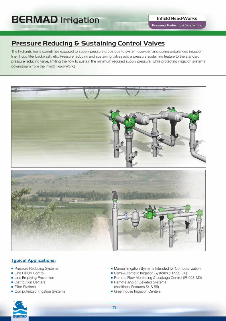
BERMAD Irrigation
71
Typical Applications:
■ Pressure Reducing Systems■ Line Fill-Up Control■ Line Emptying Prevention■ Distribution Centers■ Filter Stations■ Computerized Irrigation Systems
■ Manual Irrigation Systems Intended for Computerization■ Semi-Automatic Irrigation Systems (IR-923-D0)■ Remote Flow Monitoring & Leakage Control (IR-923-M0)■ Remote and/or Elevated Systems
(Additional Features 54 & 55)■ Greenhouse Irrigation Centers
Pressure Reducing & Sustaining Control ValvesThe hydrants line is sometimes exposed to supply pressure drops due to system over-demand during unbalanced irrigation, line fill-up, filter backwash, etc. Pressure reducing and sustaining valves add a pressure sustaining feature to the standard pressure reducing valve, limiting the flow to sustain the minimum required supply pressure, while protecting irrigation systems downstream from the Infield Head-Works.
Pressure Reducing & Sustaining
Infield Head-Works
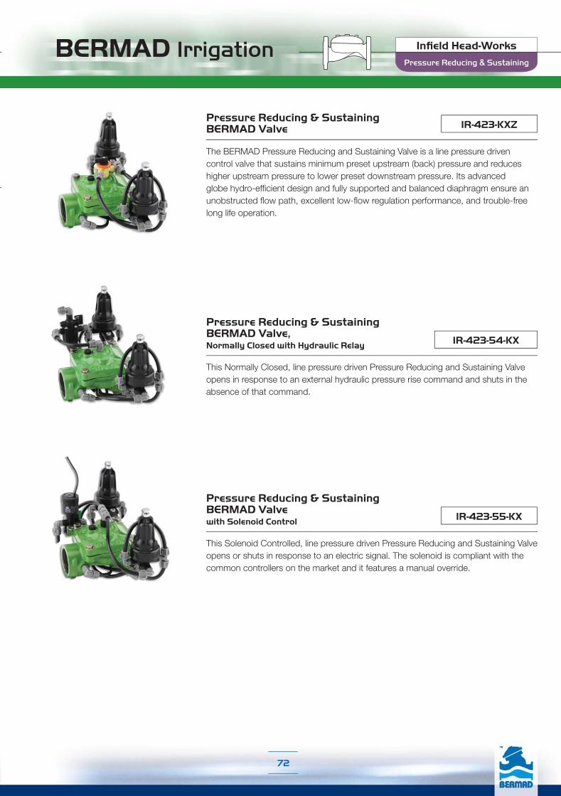
BERMAD Irrigation
72
IR-423-KXZPressure Reducing & Sustaining BERMAD Valve
The BERMAD Pressure Reducing and Sustaining Valve is a line pressure driven control valve that sustains minimum preset upstream (back) pressure and reduces higher upstream pressure to lower preset downstream pressure. Its advanced globe hydro-efficient design and fully supported and balanced diaphragm ensure an unobstructed flow path, excellent low-flow regulation performance, and trouble-free long life operation.
IR-423-54-KX
Pressure Reducing & Sustaining BERMAD Valve, Normally Closed with Hydraulic Relay
This Normally Closed, line pressure driven Pressure Reducing and Sustaining Valve opens in response to an external hydraulic pressure rise command and shuts in the absence of that command.
IR-423-55-KX
Pressure Reducing & Sustaining BERMAD Valve with Solenoid Control
This Solenoid Controlled, line pressure driven Pressure Reducing and Sustaining Valve opens or shuts in response to an electric signal. The solenoid is compliant with the common controllers on the market and it features a manual override.
Pressure Reducing & Sustaining
Infield Head-Works

BERMAD Irrigation
73
IR-123-XZPressure Reducing & Sustaining BERMAD Valve
The BERMAD Pressure Reducing and Sustaining Valve is a line pressure driven control valve that sustains minimum preset upstream (back) pressure and reduces higher upstream pressure to lower preset downstream pressure. Its engineered plastic industrial grade, hYflow ‘Y’ body with “look through” design and unitized Flexible Super Travel (FST) diaphragm and guided plug excels in its highly durable chemical and cavitation resistance, ultra-high flow capacity, and accurate and stable regulation with smooth closing.
IR-123-54-X
Pressure Reducing & Sustaining BERMAD Valve, Normally Closed with Hydraulic Relay
This Normally Closed, line pressure driven Pressure Reducing and Sustaining Valve opens in response to an external hydraulic pressure rise command and shuts in the absence of that command.
IR-123-55-X
Pressure Reducing & Sustaining BERMAD Valve with Solenoid Control
This Solenoid Controlled, line pressure driven Pressure Reducing and Sustaining Valve opens or shuts in response to an electric signal. The solenoid is compliant with the common controllers on the market and it features a manual override. The Solenoid is compliant with the common controllers on the market and it features a manual override.
Pressure Reducing & Sustaining
Infield Head-Works

BERMAD Irrigation
74
IR-923-M0-KXZ
Pressure Reducing & Sustaining BERMAD Hydrometer with Magnetic Drive
The BERMAD Pressure Reducing and Sustaining Hydrometer integrates a vertical turbine Woltman-type water meter with a diaphragm actuated hydraulic control valve. Serving as Flow Meter and Main Valve, it controls irrigation together with the irrigation controller. The Hydrometer sustains minimum preset upstream (back) pressure and reduces higher upstream pressure to lower preset downstream pressure. Its integrated “All-in-One” design saves space, cost and maintenance. The internal inlet and outlet flow straighteners save on straightening distances while maintaining accuracy.
IR-923-M0-54-KX
Pressure Reducing & Sustaining BERMAD Hydrometer, Magnetic Drive, Normally Closed with Hydraulic Relay
This Normally Closed, line pressure driven Pressure Reducing and Sustaining Hydrometer opens in response to an external hydraulic pressure rise command and shuts in the absence of that command.
IR-923-M0-55-KX
Pressure Reducing & Sustaining BERMAD Hydrometer, Magnetic Drive with Solenoid Control
This Solenoid Controlled, line pressure driven Pressure Reducing and Sustaining Hydrometer opens or shuts in response to an electric signal. The solenoid is compliant with the common controllers on the market and it features a manual override.
IR-923-D0-KXPressure Reducing & Sustaining BERMAD Automatic Metering Valve (AMV)
The BERMAD Pressure Reducing and Sustaining AMV integrates a vertical turbine Woltman-type water meter with a diaphragm actuated hydraulic control valve. Equipped with a Mechanical Shut-Off Pilot, a Pressure Reducing Pilot, and a Pressure Sustaining Pilot, it sustains minimum preset upstream (back) pressure, reduces higher upstream pressure to lower preset downstream pressure, and automatically shuts itself off after accurately delivering a manually preset quantity of water. It enables volumetric irrigation in non-computerized systems.
Pressure Reducing & Sustaining
Infield Head-Works

BERMAD Irrigation
75
Pressure Sustaining Control ValvesPressure Sustaining Valves sustain minimum back pressure, thus prioritizing pressure zones, preventing hydrants line emptying, controlling line fill-up, ensuring filter backwash pressure, etc.
Typical Applications:
■ Line Fill-Up Control■ Pressure Zone Prioritizing■ Line Emptying Prevention■ Infield Filter Backwash Pressure Sustaining ■ Computerized Irrigation Systems■ Manual Irrigation Systems Intended for Computerization
■ Semi-Automatic Irrigation Systems (IR-930-D0)■ Remote Flow Monitoring & Leakage Control (IR-930-M0)■ Remote and/or Elevated Systems
(Additional Features 54 & 55)■ Greenhouse Irrigation Centers
Pressure Sustaining
Infield Head-Works

BERMAD Irrigation
76
The BERMAD Pressure Sustaining Valve is a line pressure driven control valve that sustains minimum preset upstream (back) pressure and opens fully when line pressure is in excess of setting. Its advanced globe, hydro-efficient design, and fully supported and balanced diaphragm ensure an unobstructed flow path, excellent low-flow regulation performance, and trouble-free long life operation. The Model IR-430-RXZ includes Metal Accessories.
Pressure Sustaining BERMAD Valve IR-430-RXZ
IR-430-KXZ
Pressure Sustaining BERMAD Valve with Hydraulic Control
This Normally Open, line pressure driven Pressure Sustaining Valve shuts in response to an external hydraulic pressure rise command. The Model IR-430-50-RXZ includes Metal Accessories.
IR-430-50-RXZ
IR-430-50-KXZ
IR-430-54-KX
This Normally Closed, line pressure driven Pressure Sustaining Valve opens in response to an external hydraulic pressure rise command and shuts in the absence of that command.
Pressure Sustaining BERMAD Valve, Normally Closed with Hydraulic Relay
IR-430-55-KX
This Solenoid Controlled, line pressure driven Pressure Sustaining Valve opens or shuts in response to an electric signal. The solenoid is compliant with the common controllers on the market and it features a manual override.
Pressure Sustaining BERMAD Valve with Solenoid Control
Pressure Sustaining
Infield Head-Works

BERMAD Irrigation
77
IR-130-XZ Pressure Sustaining BERMAD Valve
The BERMAD Pressure Sustaining Valve is a line pressure driven control valve that sustains minimum preset upstream (back) pressure and opens fully when line pressure is in excess of setting. Its engineered plastic industrial grade, hYflow ‘Y’ body with “look through” design and unitized Flexible Super Travel (EST) diaphragm and guided plug excels in its highly durable chemical and cavitation resistance, ultra-high flow capacity, and accurate and stable regulation with smooth closing.
IR-130-54-X Pressure Sustaining BERMAD Valve, Normally Closed with Hydraulic Relay
This Normally Closed, line pressure driven Pressure Sustaining Valve opens in response to an external hydraulic pressure rise command and shuts in the absence of that command.
IR-130-55-XPressure Sustaining BERMAD Valve with Solenoid Control
This Solenoid Controlled, line pressure driven Pressure Sustaining Valve opens or shuts in response to an electric signal. The solenoid is compliant with the common controllers on the market and it features a manual override.
Pressure Sustaining
Infield Head-Works

BERMAD Irrigation
78
IR-930-M0-KXZ
Pressure Sustaining BERMAD Hydrometer with Magnetic Drive
The BERMAD Pressure Sustaining Hydrometer integrates a vertical turbine Woltman-type water meter with a diaphragm actuated hydraulic control valve. Serving as Flow Meter and Main Valve, it controls irrigation together with the irrigation controller. The Hydrometer sustains minimum preset upstream (back) pressure and opens fully when line pressure is in excess of setting. Its integrated “All-in-One” design saves space, cost and maintenance. The internal inlet and outlet flow straighteners save on straightening distances while maintaining accuracy.
IR-930-M0-54-KX
Pressure Sustaining BERMAD Hydrometer, Magnetic Drive, Normally Closed with Hydraulic Relay
This Normally Closed, line pressure driven Pressure Sustaining Hydrometer opens in response to an external hydraulic pressure rise command and shuts in the absence of that command.
IR-930-M0-55-KX
Pressure Sustaining BERMAD Hydrometer, Magnetic Drive with Solenoid Control
This Solenoid Controlled, line pressure driven Pressure Sustaining Hydrometer opens or shuts in response to an electric signal. The solenoid is compliant with the common controllers on the market and it features a manual override.
IR-930-D0-KXPressure Sustaining BERMAD Automatic Metering Valve (AMV)
The BERMAD Pressure Sustaining AMV integrates a vertical turbine Woltman-type water meter with a diaphragm actuated hydraulic control valve. Equipped with a Mechanical Shut-Off Pilot and a 3-Way Pressure Sustaining Pilot, it sustains minimum preset upstream (back) pressure, opens fully when line pressure is in excess of setting, and automatically shuts itself off after accurately delivering a manually preset quantity of water. It enables volumetric irrigation in non-computerized systems.
Pressure Sustaining
Infield Head-Works

BERMAD Irrigation
79
Typical Applications:
■ Multiple Independent Consumer Systems■ Line Fill-Up Control■ Distribution Centers■ Computerized Irrigation Systems■ Manual Irrigation Systems Intended for Computerization
■ Semi-Automatic Irrigation Systems (IR-970-D0)■ Remote Flow Monitoring & Leakage Control (IR-970-M0)■ Remote and/or Elevated Systems
(Additional Features 54 & 55)■ Greenhouse Irrigation Centers
Flow Control ValvesMeters, filters, pumps and other distribution equipment might experience flows that exceed their operating capacity due to system over-demand during unbalanced irrigation, line fill-up, filter backwash, etc. Flow Control Valves maintain a preset maximum flow rate regardless of variations in demand or upstream/downstream pressure.
Flow Control
Infield Head-Works

BERMAD Irrigation
80
IR-470-bKUZFlow Control BERMAD Valve with Hydraulic Control
The BERMAD Flow Control Valve is a line pressure driven control valve that limits system demand to a constant preset maximum flow rate. It is commanded by a flow pilot, which senses the P across an orifice installed upstream of the valve. Its advanced globe, hydro-efficient design and fully supported and balanced diaphragm ensure an unobstructed flow path, excellent low-flow regulation performance, and trouble-free long life operation.
IR-470-54-bKU Flow Control BERMAD Valve, Normally Closed with Hydraulic Relay
This Normally Closed, line pressure driven Flow Control Valve opens in response to an external hydraulic pressure rise command and shuts in the absence of that command.
IR-470-55-bKUFlow Control BERMAD Valve with Solenoid Control
This Solenoid Controlled, line pressure driven Flow Control Valve opens or shuts in response to an electric signal. The solenoid is compliant with the common controllers on the market and it features a manual override.
Flow Control
Infield Head-Works

BERMAD Irrigation
81
IR-170-bDZ Flow Control BERMAD Valve
The BERMAD Flow Control Valve is a line pressure driven control valve that limits system demand to a constant preset maximum flow rate. It is commanded by a flow pilot, which senses the ΔP across a Differential Pressure Duct installed in the valve. Its engineered plastic industrial grade, hYflow ‘Y’ body with “look through” design and unitized Flexible Super Travel (FST) diaphragm and guided plug excels in its highly durable chemical and cavitation resistance, ultra-high flow capacity, and accurate and stable regulation with smooth closing.
IR-170-54-bD Flow Control BERMAD Valve, Normally Closed with Hydraulic Relay
This Normally Closed, line pressure driven Flow Control Valve opens in response to an external hydraulic pressure rise command and shuts in the absence of that command.
IR-170-55-bDFlow Control BERMAD Valve with Solenoid Control
This Solenoid Controlled, line pressure driven Flow Control Valve opens or shuts in response to an electric signal. The solenoid is compliant with the common controllers on the market and it features a manual override.
Flow Control
Infield Head-Works

BERMAD Irrigation
82
IR-970-M0-KVZ Flow Control BERMAD Hydrometer with Magnetic Drive
The BERMAD Flow Control Hydrometer integrates a vertical turbine Woltman-type water meter, with a diaphragm actuated hydraulic control valve. Commanded by a paddle flow pilot, which includes a paddle positioned within the flow stream, it limits system demand to a constant preset maximum flow rate. Its integrated “All-in-One” design saves space, cost and maintenance. The internal inlet and outlet flow straighteners save on straightening distances while maintaining accuracy.
IR-970-M0-54-KV
Flow Control BERMAD Hydrometer, Magnetic Drive, Normally Closed with Hydraulic Relay
This Normally Closed, line pressure driven Flow Control Hydrometer opens in response to an external hydraulic pressure rise command and shuts in the absence of that command.
IR-970-M0-55-KV Flow Control BERMAD Hydrometer, Magnetic Drive with Solenoid Control
This Solenoid Controlled, line pressure driven Flow Control Hydrometer opens or shuts in response to an electric signal. The solenoid is compliant with the common controllers on the market and it features a manual override.
IR-970-D0-KVFlow Control BERMAD Automatic Metering Valve (AMV)
The BERMAD Flow Control AMV integrates a vertical turbine Woltman-type water meter with a diaphragm actuated hydraulic control valve. Equipped with a Mechanical Shut-Off Pilot and a paddle flow pilot, which includes a paddle positioned within the flow stream, it limits system demand to a constant preset maximum flow rate and automatically shuts itself off after accurately delivering a manually preset quantity of water. It enables volumetric irrigation in non-computerized systems.
Flow Control
Infield Head-Works

BERMAD Irrigation
83
Typical Applications:
■ Multiple Independent Consumer Systems■ Pressure Reducing Systems■ Line Fill-Up Control■ Distribution Centers■ Computerized Irrigation Systems■ Manual Irrigation Systems Intended for Computerization
■ Semi-Automatic Irrigation Systems (IR-972-D0)■ Remote Flow Monitoring & Leakage Control (IR-972-M0)■ Remote and/or Elevated Systems
(Additional Features 54 & 55)■ Greenhouse Irrigation Centers
Flow Control & Pressure Reducing ValvesFlow Control Valves maintain system preset maximum flow rate, preventing flows from exceeding the designed flow rates caused by system over-demand during unbalanced irrigation, line fill-up, etc. Flow Control and Pressure Reducing Valves add a pressure reducing feature to the standard Flow Control Valve, preventing system over-demand while protecting irrigation systems downstream from the Infield Head-Works.
Flow Control & Pressure Reducing
Infield Head-Works

BERMAD Irrigation
84
IR-472-bKUZFlow Control & Pressure Reducing BERMAD Valve
The BERMAD Flow Control and Pressure Reducing Valve is a line pressure driven control valve that limits system demand and reduces downstream pressure to constant preset maximum values. Its advanced globe hydro-efficient design and fully supported and balanced diaphragm ensure an unobstructed flow path, excellent low-flow regulation performance, and trouble-free long life operation.
IR-472-54-bKU
Flow Control & Pressure Reducing BERMAD Valve, Normally Closed with Hydraulic Relay
This Normally Closed, line pressure driven Flow Control and Pressure Reducing Valve opens in response to an external hydraulic pressure rise command and shuts in the absence of that command.
IR-472-55-bKU
Flow Control & Pressure Reducing BERMAD Valve with Solenoid Control
This Solenoid Controlled, line pressure driven Flow Control and Pressure Reducing Valve opens or shuts in response to an electric signal. The solenoid is compliant with the common controllers on the market and it features a manual override.
Flow Control & Pressure Reducing
Infield Head-Works

BERMAD Irrigation
85
IR-172-bDZ Flow Control & Pressure Reducing BERMAD Valve
The BERMAD Flow Control and Pressure Reducing Valve is a line pressure driven control valve that limits system demand and reduces downstream pressure to constant preset maximum values. Its engineered plastic industrial grade, hYflow ‘Y’ body with “look through” design and unitized Flexible Super Travel (FST) diaphragm and guided plug excels in its highly durable chemical and cavitation resistance, ultra-high flow capacity, and accurate and stable regulation with smooth closing.
IR-172-54-bD
Flow Control & Pressure Reducing BERMAD Valve, Normally Closed with Hydraulic Relay
This Normally Closed, line pressure driven Flow Control and Pressure Reducing Valve opens in response to an external hydraulic pressure rise command and shuts in the absence of that command.
IR-172-55-bD
Flow Control & Pressure Reducing BERMAD Valve with Solenoid Control
This Solenoid Controlled, line pressure driven Flow Control and Pressure Reducing Valve opens or shuts in response to an electric signal. The solenoid is compliant with the common controllers on the market and it features a manual override.
Flow Control & Pressure Reducing
Infield Head-Works

BERMAD Irrigation
86
IR-972-M0-KVZ
Flow Control & Pressure Reducing BERMAD Hydrometer with Magnetic Drive
The BERMAD Flow Control and Pressure Reducing Hydrometer integrates a vertical turbine Woltman-type water meter, with a diaphragm actuated hydraulic control valve. It limits system demand and reduces downstream pressure to constant preset maximum values. Its integrated “All-in-One” design saves space, cost and maintenance. The internal inlet and outlet flow straighteners save on straightening distances while maintaining accuracy.
IR-972-M0-54-KV
Flow Control & Pressure Reducing BERMAD Hydrometer, Magnetic Drive, Normally Closed with Hydraulic Relay
This Normally Closed, line pressure driven Flow Control and Pressure Reducing Hydrometer opens in response to an external hydraulic pressure rise command and shuts in the absence of that command.
IR-972-M0-55-KV
Flow Control & Pressure Reducing BERMAD Hydrometer, Magnetic Drive with Solenoid Control
This Solenoid Controlled, line pressure driven Flow Control and Pressure Reducing Hydrometer opens or shuts in response to an electric signal. The solenoid is compliant with the common controllers on the market and it features a manual override.
IR-972-D0-KVFlow Control & Pressure Reducing BERMAD Automatic Metering Valve (AMV)
The BERMAD Flow Control and Pressure Reducing AMV integrates a vertical turbine Woltman-type water meter with a diaphragm actuated hydraulic control valve. Equipped with a Mechanical Shut-Off Pilot, a paddle flow pilot and a Pressure Reducing Pilot, it limits system demand and reduces downstream pressure to constant preset maximum values, and automatically shuts itself off after accurately delivering a manually preset quantity of water. It enables volumetric irrigation in non-computerized systems.
Flow Control & Pressure Reducing
Infield Head-Works
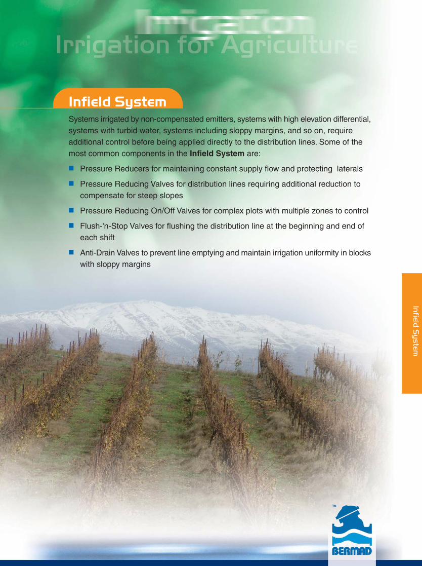
Infield SystemSystems irrigated by non-compensated emitters, systems with high elevation differential,systems with turbid water, systems including sloppy margins, and so on, requireadditional control before being applied directly to the distribution lines. Some of themost common components in the Infield System are:
■ Pressure Reducers for maintaining constant supply flow and protecting laterals
■ Pressure Reducing Valves for distribution lines requiring additional reduction to compensate for steep slopes
■ Pressure Reducing On/Off Valves for complex plots with multiple zones to control
■ Flush-'n-Stop Valves for flushing the distribution line at the beginning and end of each shift
■ Anti-Drain Valves to prevent line emptying and maintain irrigation uniformity in blockswith sloppy margins
Infield
System

BERMAD Irrigation
695
690
685
670
675
Infield System
Laterals
Distribution Line
Infi
eld
Sys
tem
695
690
685
670
675
89

Pressure Reducing
Flush-’n-Stop
Anti-Drain
Applications Guide
Infield System
90
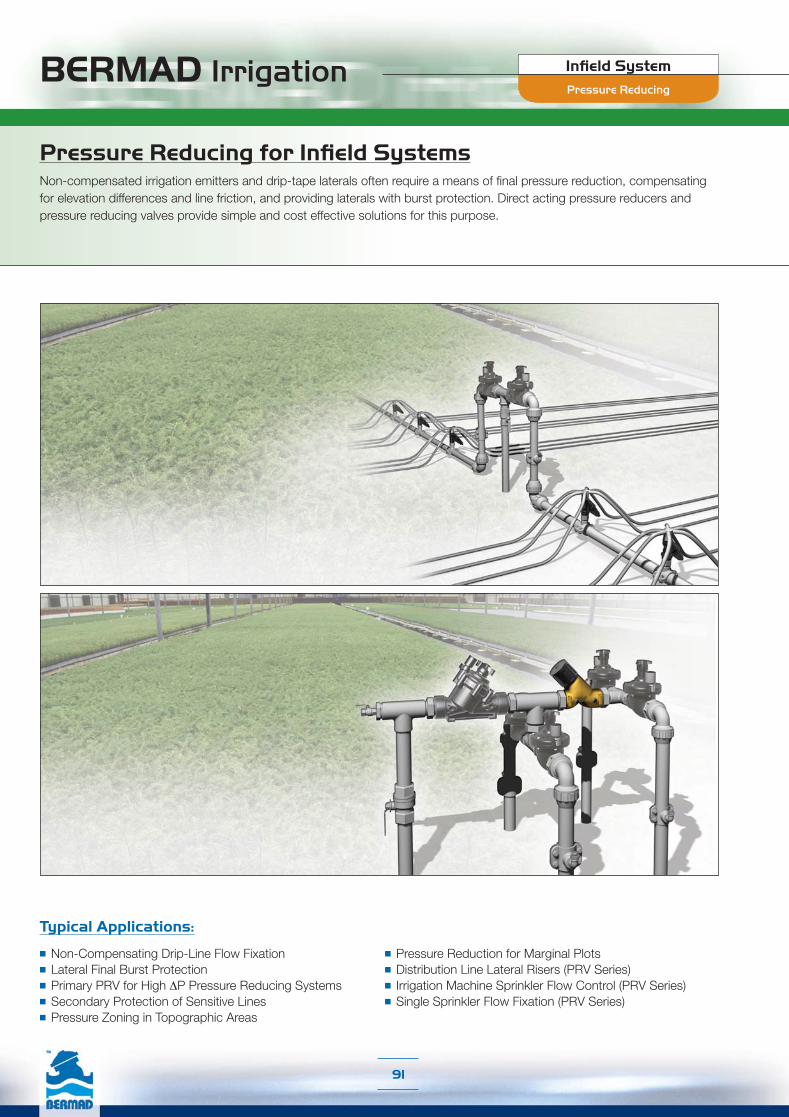
BERMAD Irrigation Infield System
91
Typical Applications:
■ Non-Compensating Drip-Line Flow Fixation■ Lateral Final Burst Protection■ Primary PRV for High ΔP Pressure Reducing Systems■ Secondary Protection of Sensitive Lines■ Pressure Zoning in Topographic Areas
■ Pressure Reduction for Marginal Plots■ Distribution Line Lateral Risers (PRV Series)■ Irrigation Machine Sprinkler Flow Control (PRV Series)■ Single Sprinkler Flow Fixation (PRV Series)
Pressure Reducing for Infield SystemsNon-compensated irrigation emitters and drip-tape laterals often require a means of final pressure reduction, compensating for elevation differences and line friction, and providing laterals with burst protection. Direct acting pressure reducers and pressure reducing valves provide simple and cost effective solutions for this purpose.
Pressure Reducing

BERMAD Irrigation Infield System
92
The BERMAD Adjustable Direct Acting Pressure Reducer is actuated by a pressure responsive diaphragm, which seeks to reach equilibrium between hydraulic and set spring force. The BERMAD Mode ¾”-PRV is built of reinforced plastic that endows it with excellent hydraulic performance capabilities and high mechanical strength. It reduces higher upstream pressure to lower constant downstream pressure regardless of fluctuating demand or varying upstream pressure. The Model ¾”-PRV-05 is supplied with a special throttling plug and elastomeric seal, and reduces pressure even under conditions of near zero demand.
Adjustable Direct Acting BERMAD Plastic Pressure Reducers ¾”-PRV-05
¾”-PRV
Adjustable Direct Acting BERMAD Plastic Pressure Reducer
This BERMAD Adjustable Direct Acting Pressure Reducer suits Flow Range of 0.45-7 m3/h; 2-31 gpm.The Model ¾”-PRV-05 is supplied with a special throttling plug and elastomeric seal, and suits Flow Ranges of 0.1-7 m3/h; 0.4-31 gpm
1”-PRV-05
1”-PRV
This BERMAD Adjustable Direct Acting Pressure Reducer has a brass body and reinforced plastic actuator assembly, which endow it with particularly high mechanical strength. It is supplied with a special throttling plug and elastomeric seal. It reduces pressure even under conditions of near zero demand, and seals drip-tight under no-flow conditions. It suits Flow Ranges of 0.45-18 m3/h; 2-80 gpm.
Adjustable Direct Acting BERMAD Metal Pressure Reducer 1½”-PRV
Direct Acting BERMAD Metal Pressure Reducer with Manual Closure
This BERMAD Direct Acting Pressure Reducer has a brass body and reinforced plastic actuator assembly, which endow it with excellent hydraulic performance capabilities and particularly high mechanical strength. Supplied with a special throttling plug, it reduces higher upstream pressure to lower constant downstream pressure even under conditions of near zero demand, and seals drip-tight under no-flow conditions.
2”-PRV
Pressure Reducing
¾”-PRV ¾”-PRV-05Low-Flow
1”-PRV 1”-PRV-05Low-Flow
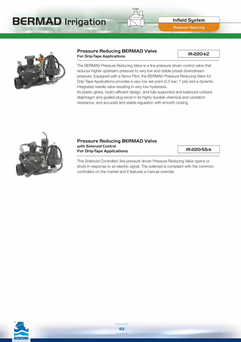
BERMAD Irrigation Infield System
93
IR-220-bZPressure Reducing BERMAD ValveFor Drip-Tape Applications
The BERMAD Pressure Reducing Valve is a line pressure driven control valve that reduces higher upstream pressure to very low and stable preset downstream pressure. Equipped with a Servo Pilot, the BERMAD Pressure Reducing Valve for Drip-Tape Applications provides a very low set point (0.5 bar; 7 psi) and a dynamic integrated needle valve resulting in very low hysteresis.Its plastic globe, hydro-efficient design, and fully supported and balanced unitized diaphragm and guided plug excel in its highly durable chemical and cavitation resistance, and accurate and stable regulation with smooth closing.
IR-220-55-b
Pressure Reducing BERMAD Valve with Solenoid ControlFor Drip-Tape Applications
This Solenoid Controlled, line pressure driven Pressure Reducing Valve opens or shuts in response to an electric signal. The solenoid is compliant with the common controllers on the market and it features a manual override.
Pressure Reducing
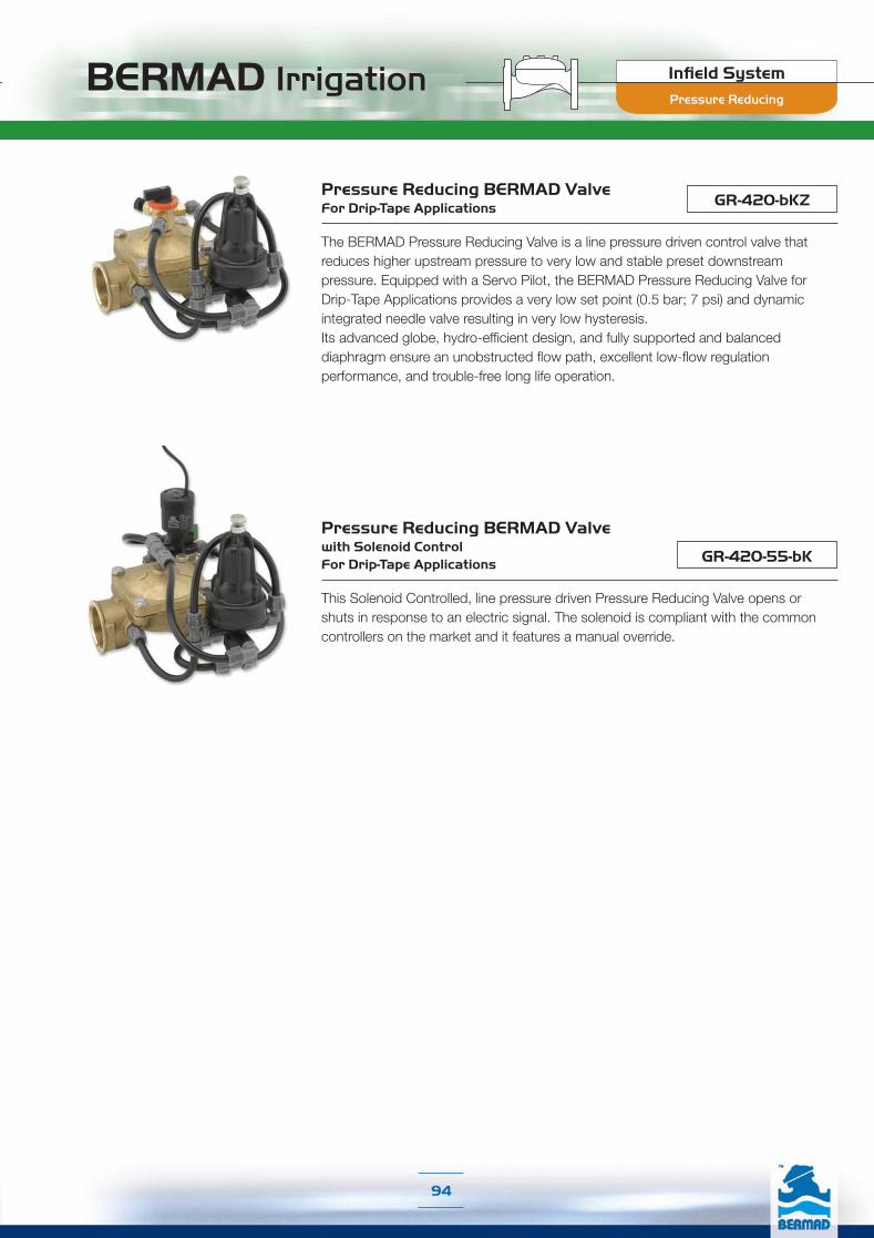
BERMAD Irrigation Infield System
94
GR-420-bKZPressure Reducing BERMAD Valve For Drip-Tape Applications
The BERMAD Pressure Reducing Valve is a line pressure driven control valve that reduces higher upstream pressure to very low and stable preset downstream pressure. Equipped with a Servo Pilot, the BERMAD Pressure Reducing Valve for Drip-Tape Applications provides a very low set point (0.5 bar; 7 psi) and dynamic integrated needle valve resulting in very low hysteresis. Its advanced globe, hydro-efficient design, and fully supported and balanced diaphragm ensure an unobstructed flow path, excellent low-flow regulation performance, and trouble-free long life operation.
GR-420-55-bK
Pressure Reducing BERMAD Valve with Solenoid ControlFor Drip-Tape Applications
This Solenoid Controlled, line pressure driven Pressure Reducing Valve opens or shuts in response to an electric signal. The solenoid is compliant with the common controllers on the market and it features a manual override.
Pressure Reducing

BERMAD Irrigation Infield System
95
Typical Applications:
■ Plain Plots with Sloppy Margins■ Downhill Sprinkler Lines■ Hillside Irrigation Machines
Anti-Drain ValvesLine emptying or fill-up have a damaging effect on irrigation lines and equipment, and on irrigation uniformity. Anti-drain valves prevent line emptying when installed at the beginning of plain plot sloppy margins or on risers from downhill distribution lines or irrigation machines. The main distribution line is then remain under low pressure preventing damage from line emptying or fill-up, and enabling all areas of the plot to start/stop irrigation simultaneously, thereby contributing to irrigation uniformity.
IR-205-05Anti-Drain BERMAD Valve
The BERMAD Anti-Drain Valve is a spring loaded, diaphragm actuated valve that opens upon pressurizing the irrigation system and shuts off drip-tight when the system reaches closure pressure. Maintained pressure is determined by the valve’s auxiliary closing spring force.
GR-405-05Anti-Drain BERMAD Valve
The BERMAD Anti-Drain Valve is a spring loaded diaphragm actuated valve that opens upon pressurizing the irrigation system and shuts off drip-tight when the system reaches closure pressure. Maintained pressure is determined by the valve’s auxiliary closing spring force.
Anti-Drain

BERMAD Irrigation Infield System
96
IR-300-eLMOFlush-’n-Stop BERMAD Valve
The BERMAD Flush-'n-Stop Valve is a double chambered, hydraulically operated, diaphragm actuated control valve. Equipped with an auxiliary opening spring and a flow stem, it enables automatic opening when the system reaches closure pressure and settable opening rate, ensuring line pressure build-up for secure closing.
Typical Applications:
■ Distribution Line Flush-’n-Stop❏ Drip Systems❏ Sprinklers & Micro-Sprinklers❏ Greenhouses
■ Flooding Tables Drainage (with External Pressure)■ Irrigation Machine Line Flush-’n-Stop
Flush-'n-Stop ValvesAutomatic flushing of distribution lines at the beginning and end of each irrigation cycle helps prevent dirt from accumulating at the end of the line, where flow velocity is low. This reduces the risk of emitters clogging, resulting in more uniformity and less maintenance.
Flush-'n-Stop

Engineering Data
En
gin
eering
Da
ta

Engineering Data■ IR-400 Series page 100-109
■ IR-100 Series page 110-116
■ IR-900-M Series page 117-130
■ IR-900-D Series page 131-140
■ WW-700 Series page 141-152
■ Water Meters page 153-158
■ IR-350 Series page 159-163
■ IR-200 Series page 164-168
■ IR-300 Series page 169-172
■ IR-R00 Series page 173-176
■ PRV Series page 177-181
■ AR Series page 182-186
En
gin
eeri
ng
Da
ta

Engineering DataIR-400 Series

Engineering Data
400 SeriesBERMAD Irrigation
[1] Fastening BoltsOnly four bolts (up to 10"; DN250 valve) fasten
valve cover to body, ensuring quick in-line inspection
and service.
[2] Valve CoverLocates, centralizes and fastens diaphragm and spring
ensuring smooth and accurate performance. Simple
construction enables quick in-line inspection and service.
[3] Auxiliary Closing SpringOne single spring fully meets valve requirements
for operating pressure range, ensuring low opening
pressure and secured closing.
[4] Diaphragm AssemblyOne piece elastomeric assembly that includes a
peripherally supported flexible diaphragm, vulcanized
with a rugged radial seal disk.
No need for special types of diaphragms to meet
different operating conditions.
Progressive dynamic guidance, resulting in
exceptionally stable action and restrained closing.
Valve opens and closes drip tight even with very low
pressure supply.
Perfectly balanced diaphragm with no distortion
caused by uneven hydraulic forces on shut-off or
during regulation.
Exceptionally stable and chatter-free action during
shut-off and pressure regulation.
[5] Body ThreadsNo need for nuts, simplifying valve disassembling and
assembling for maintenance.
[6] Wide Body ValveHydro-dynamically designed for efficient flow with minimal pressure loss and excellent resistance to cavitation.
[6.1] Diaphragm Supporting & Guiding
[6.2] Diaphragm Balancing Chamber
[6.3] Valve Seat: Full bore, valve port area clear of obstructions; no ribs or stem guides. Flow entrance is vertical to seal disk.
[6.4] End Connections: Conforms to pressure ratings and standards of: ISO, ANSI, JIS, BS, and others.
Product Parts Features
[1]
[2]
[3]
[4]
[5]
[6.4]
[6]
[6.1]
[6.2][6.3]
101
For spare parts ordering, Please use BERMAD “Spare Parts Ordering Guide”
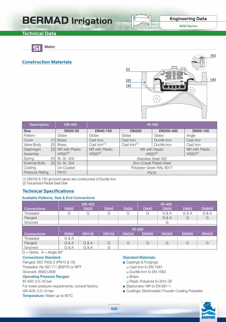
BERMAD Irrigation Engineering Data
400 Series
SI Metric
Technical Data
Construction Materials
[1]
[2]
[3]
[4]
[5]
Technical Specifications
Connections Standard:Flanged: ISO 7005-2 (PN10 & 16)Threaded: Rp ISO 7/1 (BSP.P) or NPTGrooved: ANSI C606Operating Pressure Ranges:IR-400: 0.5-16 barFor lower pressure requirements, consult factoryGR-400: 0.5-10 barTemperature: Water up to 60°C
Standard Materials:Castings & Forgings:❑ Cast Iron to EN 1561❑ Ductile Iron to EN 1563❑ Brass❑ Plasti: Polyamid 6+30% GFElastomers: NR to EN 681-1Coatings: Electrostatic Powder Coating Polyester
Available Patterns, Size & End Connections
GR-400 IR-400Connections DN20 DN25 DN40 DN50 DN40 DN50 DN65 DN80RThreaded G G G G G G & A G & A G & AFlanged G & A G GGrooved G
IR-400Connections DN80 DN100 DN150 DN200 DN250 DN300 DN350 DN400Threaded G & AFlanged G & A G & A G G G G G GGrooved G & A G & A G
G = Globe, A = Angle 90°
SizePattern
[1]Cover[2]Valve Body[3]Diaphragm
Assembly[4]Spring[5]External Bolts
CoatingPressure Rating
DN20-50GlobeBrassBrassNR with PlasticVRSD(2)
St. St. 302St. St. 304Un-CoatedPN10
(1) DN100 & 150 grooved valves are constructed of Ductile Iron(2) Vulcanized Radial Seal Disk
Description IR-400GR-400
Zinc-Cobalt Plated SteelPolyester Green RAL 6017
PN16
DN40-150GlobeCast IronCast Iron(1)
NR with PlasticVRSD(2)
DN200GlobeCast IronCast Iron(1)
DN250-400GlobeDuctile IronDuctile Iron
DN50-100AngleCast IronCast IronNR with PlasticVRSD(2)
NR with PlasticVRSD(2)
Stainless Steel 302
102

Engineering Data
400 SeriesBERMAD Irrigation
Globe Pattern
Dimensions & Weights
H
R
LW
SI Metric
DN50205155155789
SizeL (mm)H (mm)W (mm)R (mm)Weight (kg)
DN6520517817889
10.5
DN80R21020020010012.1
DN10032024222311228
DN250605460405202140
DN300725635580242290
DN350742655587260358
DN400742965600300377
DN200500430365170125
DN15041534530614068
DN8025021020010019
Flanged
DN401538798292
DN50180114119394
DN65210132129455.7
DN80R210140129535.8
DN802551651705513
DN50205108119315
DN8025015517046
10.6
DN10032019120461
16.2
DN1504153023068549
SizeL (mm)H (mm)W (mm)R (mm)Weight (kg)
Threaded Grooved
Angle Pattern
K
h
H
LW
SizeL (mm)H (mm)W (mm)h (mm)K (mm)Weight (kg)
DN508613611961564.4
DN6511018013193665.8
DN80R11017813191667
DN1001602232041125816
DN10016022322311211226
DN8015320520010110017
DN5012116015583789
DN80110184170805511
DN80120194170904510
FlangedThreaded Grooved
Globe Pattern GR-400
L
H
R
W
SizeL (mm)H (mm)W (mm)R (mm)Weight (kg)
DN20112682272
0.95
DN25115702372
0.95
DN50180103391184
DN401508932941.5
Control Chamber Displacement Volume (liter)
DN50 DN65 DN80 DN100 DN150 DN200 DN250 DN300-400
0.113 0.179 0.291 0.668 1.973 3.858 3.858 13.75
103
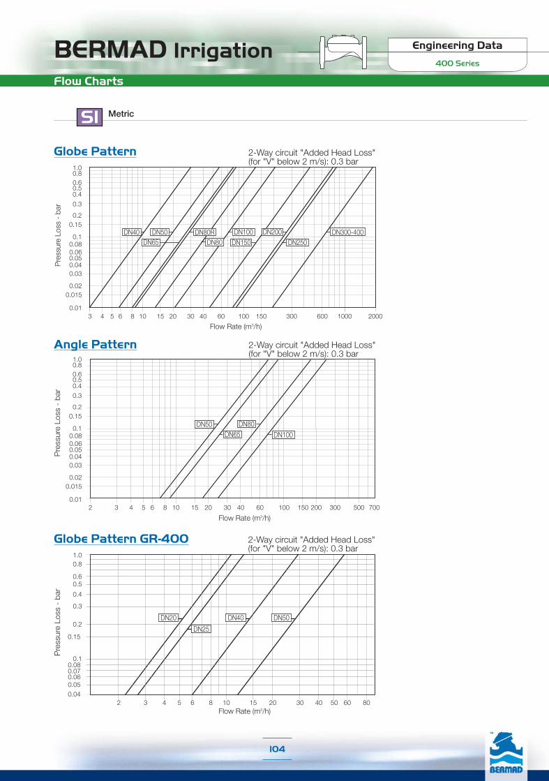
BERMAD Irrigation Engineering Data
400 Series
Flow Charts
SI Metric
Globe Pattern
Pre
ssur
e Lo
ss -
bar
Flow Rate (m3/h)
DN65DN300-400
3 4 5 6 8 10 15 20 30 40 60 100 150 300 600 1000 2000
DN50 DN80RDN80
DN100DN150
DN200DN250
DN40
0.06
1.00.80.60.50.4
0.3
0.20.15
0.01
0.10.08
0.050.040.03
0.020.015
Angle Pattern
Pre
ssur
e Lo
ss -
bar
Flow Rate (m3/h)2 3 4 5 6 8 10 15 20 30 40 60 100 150 200 300 500 700
1.00.80.60.50.4
0.3
0.20.15
0.01
0.06
0.10.08
0.050.040.03
0.020.015
DN65DN50 DN80
DN100
Globe Pattern GR-400
2 3 4 5 6 8 10 15 20 30 40 50 60 80
1.00.8
0.60.5
0.4
0.3
0.2
0.15
0.10.080.070.060.050.04
Flow Rate (m3/h)
DN25
DN20 DN40 DN50
Pre
ssur
e Lo
ss -
bar
2-Way circuit "Added Head Loss"(for "V" below 2 m/s): 0.3 bar
2-Way circuit "Added Head Loss"(for "V" below 2 m/s): 0.3 bar
2-Way circuit "Added Head Loss"(for "V" below 2 m/s): 0.3 bar
104

Engineering Data
400 SeriesBERMAD IrrigationFlow Properties
Where:Kv = Valve flow coefficient (flow in m3/h at 1bar Diff. Press.)Cv = Valve flow coefficient (flow in gpm at Diff. Press. 1psi)Q = Flow rate (m3/h ; gpm)P = Differential pressure (bar ; psi)
Gf = Liquid specific gravity (Water = 1.0)
Valve flow coefficient, Kv or Cv Kv(Cv)=Q Gf
P
Cv = 1.155 Kv
Where:K = Flow resistance or Head loss coefficient (dimensionless)H = Head loss (m ; feet)
V = Nominal size flow velocity (m/sec ; feet/sec.)g = Acceleration of gravity (9.81 m/sec2 ; 32.18 feet/sec2)
K = H2gV2
Flow resistance or Head loss coefficient,
Equivalent Pipe Length, Leq
Where:Leq= Equivalent nominal pipe length (m ; feet)Lk = Equivalent length coefficient for turbulent flow in clean
commercial steel pipe (SCH 40)D = Nominal pipe diameter (m ; feet)
Note:The Leq values given are for general consideration only.
Leq = Lk·D
SI Metric
GlobePattern
Size DN50 DN65 DN80 DN100 DN150 DN200 DN250 DN300-400Kv 57 78 136 204 458 781 829 1,932K 3.2 4.2 2.9 4.0 4.0 4.4 3.9 3.6
Leq - m 9.1 12.1 13.7 14 27.4 45.8 108 57
105

BERMAD Irrigation Engineering Data
400 Series
US English
Technical Data
Construction Materials[1]
[2][3]
[4]
[5]
SizePattern
[1]Cover[2]Valve Body[3]Diaphragm
Assembly[4]Spring[5]External Bolts
CoatingPressure Rating
3/4-3"GlobeBrassBrassNR with PlasticVRSD(2)
St. St. 302St. St. 304Un-Coated150 psi
(1) 4 & 6" grooved valves are constructed of Ductile Iron(2) Vulcanized Radial Seal Disk
Description GR-400GR-400
Zinc-Cobalt Plated SteelPolyester Green RAL 6017
230 psi
11/2-6"GlobeCast IronCast Iron(1)
NR with PlasticVRSD(2)
8"GlobeCast IronCast Iron(1)
10-16"GlobeDuctile IronDuctile Iron
2-4"AngleCast IronCast IronNR with PlasticVRSD(2)
Technical Specifications
IR-400Connections 3” 4” 6” 8” 10” 12” 14” 16”Threaded G & AFlanged G & A G & A G G G G G GGrooved G & A G & A G
GR-400 IR-400Connections 3/4” 1” 11/2” 2” 11/2” 2” 21/2” 3”RThreaded G G G G G G & A G & A G & AFlanged G & A G GGrooved G
Available Patterns, Size & End Connections
NR with CastIron VRSD(2)
Stainless Steel 302
G = Globe, A = Angle 90°
106
Connections Standard:Flanged
ANSI B16.41 (Cast Iron)ANSI B16.42 (Ductile Iron)
Threaded: NPT or Rp ISO 7/1 (BSP.P)Grooved: ANSI C606Operating Pressure Ranges:IR-400: 7-232 psiFor lower pressure requirements, consult factoryGR-400: 7-150 psiTemperature: Water up to 140°F
Standard Materials:Castings & Forgings:❑ Cast Iron to ASTM A-126 Class B❑ Ductile Iron to ASTM A-536❑ Brass❑ Plastic: Polyamid 6+30% GFElastomers: NR to ASTM-D-2000Coatings: Electrostatic Powder Coating Polyester

Engineering Data
400 SeriesBERMAD IrrigationDimensions & Weights
US English
Control Chamber Displacement Volume (gallons)
2” 21/2” 3” 4” 6” 8 10” 12-16”
0.03 0.05 0.08 0.18 0.52 1.02 1.02 3.63
Globe Pattern GR-400
L
H
R
W
SizeL (inch)H (inch)W (inch)R (inch)Weight (lb)
3/4”47/16
211/167/8
213/16
2.1
1”41/2
23/415/16
213/16
2.1
2”71/8
41/16
19/16
45/8
8.8
11/2”57/8
31/2
11/4
311/16
3.3
Angle Pattern
K
h
H
LW
SizeL (inch)H (inch)W (inch)h (inch)K (inch)Weight (lb)
Flanged2”
33/8
53/8
411/16
23/8
23/16
9.7
21/2”45/16
71/16
53/16
311/16
25/8
12.8
3”R45/16
753/16
39/16
25/8
15.4
4”65/16
83/4
841/2
25/16
35.3
4”61/4
83/4
83/4
47/16
47/16
57.3
3”6
81/16
77/8
4315/16
37.5
2”43/4
65/16
61/8
31/4
31/16
19.8
3”43/8
71/4
611/16
31/8
23/16
24.3
Threaded Grooved3”
43/4
75/8
611/16
39/16
13/4
22.0
Globe Pattern
H
R
LW
SizeL (inch)H (inch)W (inch)R (inch)Weight (lb)
Flanged
2”81/16
61/8
61/8
31/16
19.8
21/2”81/16
77
31/2
23.1
3”R81/4
77/8
77/8
315/16
41.9
4”125/8
91/2
83/4
41/2
61.7
10”2313/16
181/8
1515/16
715/16
308.6
12”289/16
25227/8
91/2
639.3
14”291/4
2513/16
231/8
101/4
789.2
16”291/4
38235/8
1113/16
831.1
8”1911/16
1615/16
143/8
611/16
275.6
6”165/16
139/16
1251/2
149.9
3”913/16
81/4
77/8
315/16
41.9
SizeL (inch)H (inch)W (inch)R (inch)Weight (lb)
Threaded11/2”
633/8
37/8
11/8
4.4
Grooved2”
71/16
416/16
411/16
11/2
8.8
21/2”81/4
53/16
51/16
113/16
12.6
3”R81/4
51/2
51/16
21/16
12.8
3”10
61/2
611/16
23/16
28.7
2”81/16
41/4
411/16
13/16
11.0
3”913/16
61/16
611/16
16/8
23.4
4”125/8
71/2
823/8
35.7
6”165/16
157/8
121/16
33/8
108.0
107

BERMAD Irrigation Engineering Data
400 Series
Flow Charts
US English
Globe Pattern20.0
0.1
0.2
0.30.4
0.60.81.0
2.0
3.04.0
6.08.0
10.0
Pre
ssur
e Lo
ss -
psi
10 20 30 40 60 80 100 200 400 600 1,000 2,000 4,000 6,000 10,000
Flow Rate (gpm)
21/2”
3”R3”
2” 4”6”
8”10”
12”11/2”
Angle Pattern20.0
0.1
0.2
0.30.4
0.60.81.0
2.0
3.04.0
6.08.0
10.0
Pre
ssur
e Lo
ss -
psi
21/2”2” 4”
20 30 40 60 80 100 200 400 600 1,000 2,000 4,000 6,000 10,000
Flow Rate (gpm)
3”
Globe Pattern GR-400
Flow Rate (gpm)
20.0
0.1
0.2
0.30.4
0.60.81.0
2.0
3.04.0
6.08.0
10.0
Pre
ssur
e Lo
ss -
psi
3 4 6 8 10 20 30 40 60 80 100 200 300
11/2”3/4” 2”1”
2-Way circuit "Added Head Loss"(for "V" below 6.5 f/s): 4.5 psi
2-Way circuit "Added Head Loss"(for "V" below 6.5 f/s): 4.5 psi
2-Way circuit "Added Head Loss"(for "V" below 6.5 f/s): 4.5 psi
108

Engineering Data
400 SeriesBERMAD IrrigationFlow Properties
US English
GlobePattern
2” 21/2” 3” 4” 6” 8” 10” 12-16”Cv 66 90 157 236 529 902 957 2,231K 3.2 4.2 2.9 4.0 4.0 4.4 3.9 3.6
Leq - ft 30 40 45 46 90 150 354 187
Where:Kv = Valve flow coefficient (flow in m3/h at 1bar Diff. Press.)Cv = Valve flow coefficient (flow in gpm at Diff. Press. 1psi)Q = Flow rate (m3/h ; gpm)P = Differential pressure (bar ; psi)
Gf = Liquid specific gravity (Water = 1.0)
Valve flow coefficient, Kv or Cv Kv(Cv)=Q Gf
P
Cv = 1.155 Kv
Where:K = Flow resistance or Head loss coefficient (dimensionless)H = Head loss (m ; feet)
V = Nominal size flow velocity (m/sec ; feet/sec.)g = Acceleration of gravity (9.81 m/sec2 ; 32.18 feet/sec2)
K = H2gV2
Flow resistance or Head loss coefficient,
Equivalent Pipe Length, Leq
Where:Leq= Equivalent nominal pipe length (m ; feet)Lk = Equivalent length coefficient for turbulent flow in clean
commercial steel pipe (SCH 40)D = Nominal pipe diameter (m ; feet)
Note:The Leq values given are for general consideration only.
Leq = Lk·D
109

Engineering DataIR-100 Series

BERMAD Irrigation Engineering Data
100 Series -
[1] Cover RingThe cover ring fastens valve cover to body, stiffening and strengthening the valve body, enabling simple maintenance.A cover ring wrench is available.
[2] "Click-In" Bracket
For all BERMAD plastic accessories.
[3] Valve Cover
The cover’s strong construction meets rough service conditions. Optional cover types (3"; DN80 and smaller valves)are capable of accepting a Flow Stem, a Flow Stem + Position Indicator, and a 2-Way Solenoid (2W-N1 Electric Type).
[4] Auxiliary Closing SpringOne single high grade stainless steel spring provides a wide operation range, ensuring low opening pressure andsecured closing.
[5] Plug AssemblyThe unitized Flexible Super Travel (FST) plug assembly combinesa long travel guided valve plug, peripherally supported diaphragm,and replaceable diaphragm and valve seal. The diaphragm fullymeets the valve's operating pressure range requirements.
[5.1] Diaphragm Holder[5.2] Diaphragm[5.3] Plug[5.4] Plug Seal
[6] hYflow ‘Y’ Valve BodyGlass Reinforced nylon construction meets rough service conditionswith high chemical and cavitation resistance.End-to-end “look-through” design and full bore seat withunobstructed flow path, free of any in-line ribs, supporting cage,or shafts, enables ultra-high flow capacity with minimal pressure loss.
[7] End Connections
Adaptable on-site to a wide range of end connection types andsizes:
[7.1] Flanges: Plastic or metal “Corona”with elongated slots enable meetingdiverse flange standards ISO, ANSIand JIS.
[7.2] Flange adaptor external thread[7.3] Internal threads
[8] Flange AdapterArticulated flange connectionsisolate the valve from line bendingand pressure stresses.
[9] Valve Legs
Stabilizing the valve and serve alsoas mounting brackets.
[ 1 ]
[3]
[4]
[6]
[7.1]
[7.3]
[7.2]
[8]
[9]
[5]
[7.1]
[5.1]
[5.2]
[5.3]
[5.4]
[8]
Product Parts Features
[2]
111
For spare parts ordering, Please use BERMAD “Spare Parts Ordering Guide”

BERMAD Irrigation Engineering Data
100 Series -
6"; DN 150 "Y-Boxer" - Flanged 6"; DN 150 "Y-Boxer" - Grooved (Vic)
End Connection Options
Additional Valve Configurations
BSP.T; NPT Female Thread2"; DN50
BSP.F Male Thread,(for PVC Adapters)
21/2"; DN65
Union PVC adaptor21/2"; DN65
BSP.T; NPT Female Thread3"; DN80
Plastic Flange3"; DN80
Plastic Flange3"L & 4"; DN: 80L & 100
Metal Flange3"L & 4"; DN: 80L & 100
PVC Adaptor3"; DN80
Configuration Options
2"; DN50 21/2"; DN65 - Male Thread(for PVC Adapters)
3"; DN80 3"; DN 80 Angle
112
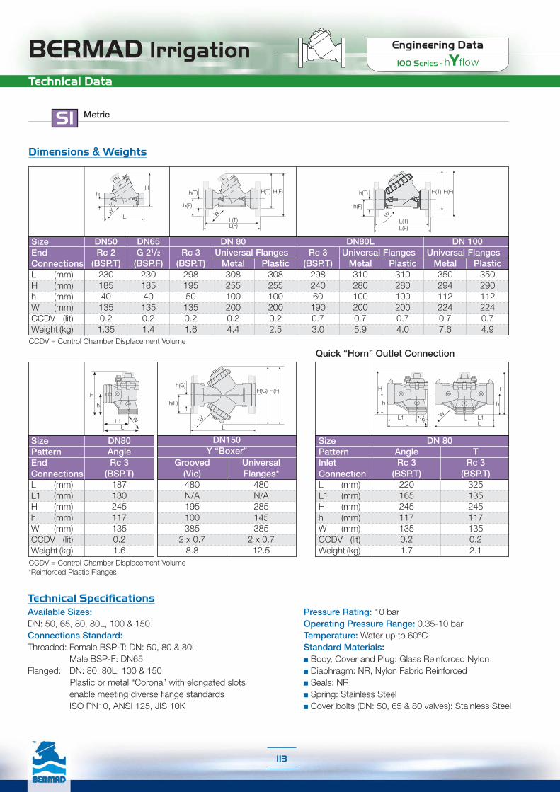
BERMAD Irrigation Engineering Data
100 Series -
Technical Data
SI Metric
CCDV = Control Chamber Displacement Volume*Reinforced Plastic Flanges
SizePatternEndConnectionsL (mm)L1 (mm)H (mm)h (mm)W (mm)CCDV (lit)Weight (kg)
DN80AngleRc 3
(BSP.T)1871302451171350.21.6
SizePatternInletConnectionL (mm)L1 (mm)H (mm)h (mm)W (mm)CCDV (lit)Weight (kg)
Quick “Horn” Outlet Connection
DN150Y “Boxer”
DNAngleRc 3
(BSP.T)2201652451171350.21.7
80T
Rc 3(BSP.T)
3251352451171350.22.1
H(G) H(F)
L
h(G)
h(F)
W
H
L1
h
LW
H
L1
h
LW
Grooved(Vic)480N/A195100385
2 x 0.78.8
UniversalFlanges*
480N/A285145385
2 x 0.712.5
Dimensions & Weights
CCDV = Control Chamber Displacement Volume
SizeEndConnectionsL (mm)H (mm)h (mm)W (mm)CCDV (lit)Weight (kg)
DN50Rc 2
(BSP.T)230185401350.21.35
DN65G 21/2
(BSP.F)230185401350.21.4
Rc 3(BSP.T)
298195501350.21.6
DN 80Universal
Metal3082551002000.24.4
FlangesPlastic
3082551002000.22.5
Rc 3(BSP.T)
298240601900.73.0
DN80LUniversal
Metal3102801002000.75.9
FlangesPlastic
3102801002000.74.0
DNUniversal
Metal3502941122240.77.6
100Flanges
Plastic3502901122240.74.9
H
L
h
W
H(T)
L(T)L(F)
H(F)
W
h(T)
h(F)
H(T) H(F)
L(T)L(F)
h(T)
h(F)
W
H
L1
h
LW
Technical SpecificationsAvailable Sizes:DN: 50, 65, 80, 80L, 100 & 150Connections Standard:Threaded: Female BSP-T: DN: 50, 80 & 80L Male BSP-F: DN65Flanged: DN: 80, 80L, 100 & 150
Plastic or metal “Corona” with elongated slots enable meeting diverse flange standardsISO PN10, ANSI 125, JIS 10K
Pressure Rating: 10 barOperating Pressure Range: 0.35-10 barTemperature: Water up to 60°CStandard Materials: Body, Cover and Plug: Glass Reinforced Nylon Diaphragm: NR, Nylon Fabric Reinforced Seals: NR Spring: Stainless Steel Cover bolts (DN: 50, 65 & 80 valves): Stainless Steel
113
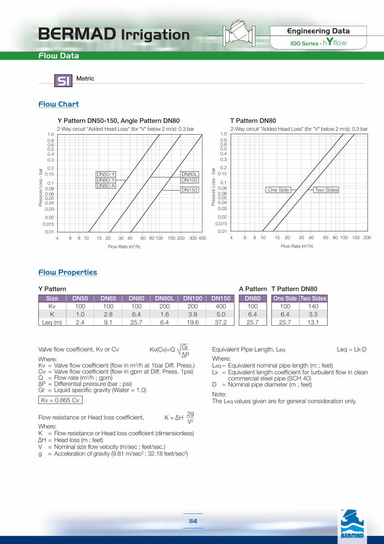
BERMAD Irrigation Engineering Data
100 Series -
Flow Data
Flow Chart
Flow Properties
MetricSI
1.00.80.60.50.40.3
0.20.15
0.01
0.10.080.060.050.040.03
0.02
0.015
Pre
ssur
e Lo
ss -
bar
Flow Rate (m3/h)
4 6 8 10 15 20 30 40 60 80 100 150 200 300 400
DN50-YDN80-Y
DN80LDN100
DN80-ADN150
Y Pattern DN50-150, Angle Pattern DN80
Size DN50 DN65 DN80 DN80L DN100 DN150Kv 100 100 100 200 200 400K 1.0 2.8 6.4 1.6 3.9 5.0
Leq (m) 2.4 9.1 25.7 6.4 19.6 37.2
DN801006.425.7
Y Pattern A Pattern T Pattern DN80One Side Two Sides
100 1406.4 3.325.7 13.1
Where:Kv = Valve flow coefficient (flow in m3/h at 1bar Diff. Press.)Cv = Valve flow coefficient (flow in gpm at Diff. Press. 1psi)Q = Flow rate (m3/h ; gpm)P = Differential pressure (bar ; psi)
Gf = Liquid specific gravity (Water = 1.0)
Valve flow coefficient, Kv or Cv Kv(Cv)=Q Gf
P
Kv = 0.865 Cv
Where:K = Flow resistance or Head loss coefficient (dimensionless)H = Head loss (m ; feet)
V = Nominal size flow velocity (m/sec ; feet/sec.)g = Acceleration of gravity (9.81 m/sec2 ; 32.18 feet/sec2)
K = H2gV2
Flow resistance or Head loss coefficient,
Equivalent Pipe Length, Leq
Where:Leq= Equivalent nominal pipe length (m ; feet)Lk = Equivalent length coefficient for turbulent flow in clean
commercial steel pipe (SCH 40)D = Nominal pipe diameter (m ; feet)
Note:The Leq values given are for general consideration only.
Leq = Lk·D
1.00.80.60.50.40.3
0.20.15
0.01
0.10.080.060.050.040.03
0.02
0.015
Pre
ssur
e Lo
ss -
bar
Flow Rate (m3/h)
4 6 8 10 15 20 30 40 60 80 100 150 200
Two Sides
T Pattern DN80
One Side
2-Way circuit "Added Head Loss" (for "V" below 2 m/s): 0.3 bar 2-Way circuit "Added Head Loss" (for "V" below 2 m/s): 0.3 bar
114

BERMAD Irrigation Engineering Data
100 Series -
Technical Data
US English
Dimensions & Weights
CCDV = Control Chamber Displacement Volume
Size
ConnectionsL (inch)H (inch)h (inch)W (inch)CCDV (gal)Weight (lb)
2”2” NPT
9 1/16
7 5/16
1 9/16
5 5/16
0.052.97
21/2”G 21/2
BSP.F9 1/16
7 5/16
1 9/16
5 5/16
0.053.08
3” NPT
11 3/4
7 11/16
1 15/16
5 5/16
0.053.52
3”Universal
Metal12 1/8
10 1/16
3 15/16
7 7/8
0.059.68
FlangesPlastic12 1/8
10 1/16
3 15/16
7 7/8
0.052.97
3” NPT
11 3/4
9 7/16
2 3/8
7 1/2
0.186.60
3”LUniversal
Metal12 3/16
113 15/16
7 7/8
0.1812.98
FlangesPlastic12 3/16
113 15/16
7 7/8
0.188.80
4Universal
Metal13 3/4
11 9/16
4 7/16
8 13/16
0.1816.72
”Flanges
Plastic13 3/4
11 7/16
4 7/16
8 13/16
0.1810.78
H
L
h
W
H(T)
L(T)L(F)
H(F)
W
h(T)
h(F)
H(T) H(F)
L(T)L(F)
h(T)
h(F)
W
CCDV = Control Chamber Displacement Volume*Reinforced Plastic Flanges
SizePatternEndConnectionsL (inch)L1 (inch)H (inch)h (inch)W (inch)CCDV (gal)Weight (lb)
3”Angle
3” NPT
7 3/8
5 1/8
9 5/8
4 5/8
5 3/8
0.053.52
SizePatternInletConnectionL (inch)L1 (inch)H (inch)h (inch)W (inch)CCDV (gal)Weight (lb)
Quick “Horn” Outlet Connection
6”Y “Boxer”
H(G) H(F)
L
h(G)
h(F)
W
H
L1
h
LW
H
L1
h
LW
3Angle
3” NPT
8 11/16
6 1/2
9 5/8
4 5/8
5 5/16
0.053.37
”T
3” NPT
12 13/16
6 1/2
9 5/8
4 5/8
5 5/16
0.054.62
Technical SpecificationsAvailable Sizes:2”, 21/2”, 3”, 3”L, 4” & 6"Connections Standard:Threaded: Female NPT: 2”, 3” & 3"L Male BSP-F: 21/2"Flanged: 3”, 3”L, 4” & 6"
Plastic or metal “Corona” with elongated slots enable meeting diverse flange standards ISO PN10,ANSI 125, JIS 10K
Pressure Rating: 145 psiOperating Pressure Range: 5-145 psiTemperature: Water up to 140°FStandard Materials:
Body, Cover and Plug: Glass Reinforced NylonDiaphragm: NR], Nylon Fabric ReinforcedSeals: NRSpring: Stainless SteelCover bolts (2”, 21/2” & 3" valves): Stainless Steel
H
L1
h
LW
Grooved(Vic)18 7/8
N/A7 11/16
3 15/16
15 3/16
0.1817.71
UniversalFlanges*
18 7/8
N/A11 1/4
5 11/16
15 3/16
0.1827.50
115

BERMAD Irrigation Engineering Data
100 Series -
Flow Data
Flow Chart
US English
2”-Y21/2”-Y3”-A
3”L4”
6”
10 50 100 500 1000 2000
Pre
ssur
e Lo
ss (p
si)
Flow Rate (gpm)
10.0
1.0
0.1
Flow Properties
Where:Kv = Valve flow coefficient (flow in m3/h at 1bar Diff. Press.)Cv = Valve flow coefficient (flow in gpm at Diff. Press. 1psi)Q = Flow rate (gpm ; m3/h)P = Differential pressure (psi ; bar)
Gf = Liquid specific gravity (Water = 1.0)
Valve flow coefficient, Cv or Kv Cv(Kv)=Q Gf
P
Cv = 1.155 Kv
Where:K = Flow resistance or Head loss coefficient (dimensionless)H = Head loss (feet ; m)
V = Nominal size flow velocity (feet/sec ; m/sec.)g = Acceleration of gravity (32.18 feet/sec2 ; 9.81 m/sec2 )
K = H2gV2
Flow resistance or Head loss coefficient,
Equivalent Pipe Length, Leq
Where:Leq= Equivalent nominal pipe length (feet ; m)Lk = Equivalent length coefficient for turbulent flow in clean
commercial steel pipe (SCH 40)D = Nominal pipe diameter (feet ; m)
Note:The Leq values given are for general consideration only.
Leq = Lk·D
Size 2” 21/2” 3” 3”L 4” 6”Cv 115 115 115 230 230 460K 1.0 2.8 6.4 1.6 3.9 5.0
Leq (ft) 8.0 29.8 84.2 21.1 64.3 122.0
3”1156.484.2
One Side Two Sides115 1606.4 3.384.2 43.0
Y Pattern A Pattern T Pattern 3”
T Pattern 3”
10.0
1.0
0.1
10 50 100 500 1000
Pre
ssur
e Lo
ss (p
si)
Flow Rate (gpm)
One Side Two Sides
2-Way circuit "Added Head Loss" (for "V" below 6.5 f/s): 4.5 psiY Pattern 2-6”, Angle Pattern 3”
2-Way circuit "Added Head Loss" (for "V" below 6.5 f/s): 4.5 psi
116

Engineering DataIR-900-M Series

BERMAD Irrigation Engineering Data
900-M Series
Product Parts Features
[1] Control HeadIncludes: Vacuum-sealed meter register, magnetically coupled to theimpeller drive. Hermetically sealed control head and its register(s).High sensitivity, providing superior accuracy that exceeds all water meterstandards. Range of Reed Switch and Opto-Electric 4-20 mA transmitteroptions provide greater flexibility in electrical pulse generation.
[2] Valve CoverLocates, centralizes and fastens diaphragm, spring, and impeller assemblyensuring smooth and accurate performance. Simple and light constructionenables quick in-line inspection and service.
[3] Auxiliary Closing SpringOne single spring fully meets valve requirements for operating pressurerange, ensuring low opening pressure and secured closing.
[4] Closure AssemblyCombining a rugged radial disk harnessed to a flexible fiber reinforceddiaphragm. The fully guided closure assembly and the carefully balancedand peripherally supported diaphragm prevent distortion and protect theelastomer, resulting in long-life and controlled actuation even under harshconditions. One diaphragm and spring fully meet the valve's operatingpressure range requirements.
[5] Impeller Assembly[5.1] Guide – Carries the transmission shaft, guides the closure assembly,
and centralizes and tightens all internal parts.[5.2] Upper Flow Straightener – Tightens the seal seat in place, straightens
outlet flow, and creates mushroom-shaped flow.[5.3] Impeller – Woltman-type impeller with tungsten carbide shaft tips
and bearings for high, long-term accuracy and negligible wear.
[6] Impeller Housing[6.1] Lower Flow Straightener – Straightens inlet flow, eliminating the
need for straight upstream pipe required in standard water meters.[6.2] Seal Seat – Metal ring vulcanized with elastomeric seal, raised and
remote from valve body to prevent cavitation damage.
[7] Integrated Calibration DeviceEnables recalibration instead of renovation when the recommendedstandard accuracy period has elapsed (The Calibration Device is stampedclosed with a metal seal).
[8] Wide BodyHydro-dynamically designed for efficient flow with minimal pressure lossand excellent resistance to cavitation.
[8.1] End Connections conform to pressure ratings and standards:ISO, ANSI, JIS, BS, and others.
[ 1 ]
[2]
[3]
[4]
[5.1]
[5.2]
[5.3]
[6.1]
[8]
[7]
[8.1]
[8.1]
[5]
[6][6.2]
118
For spare parts ordering, Please use BERMAD “Spare Parts Ordering Guide”
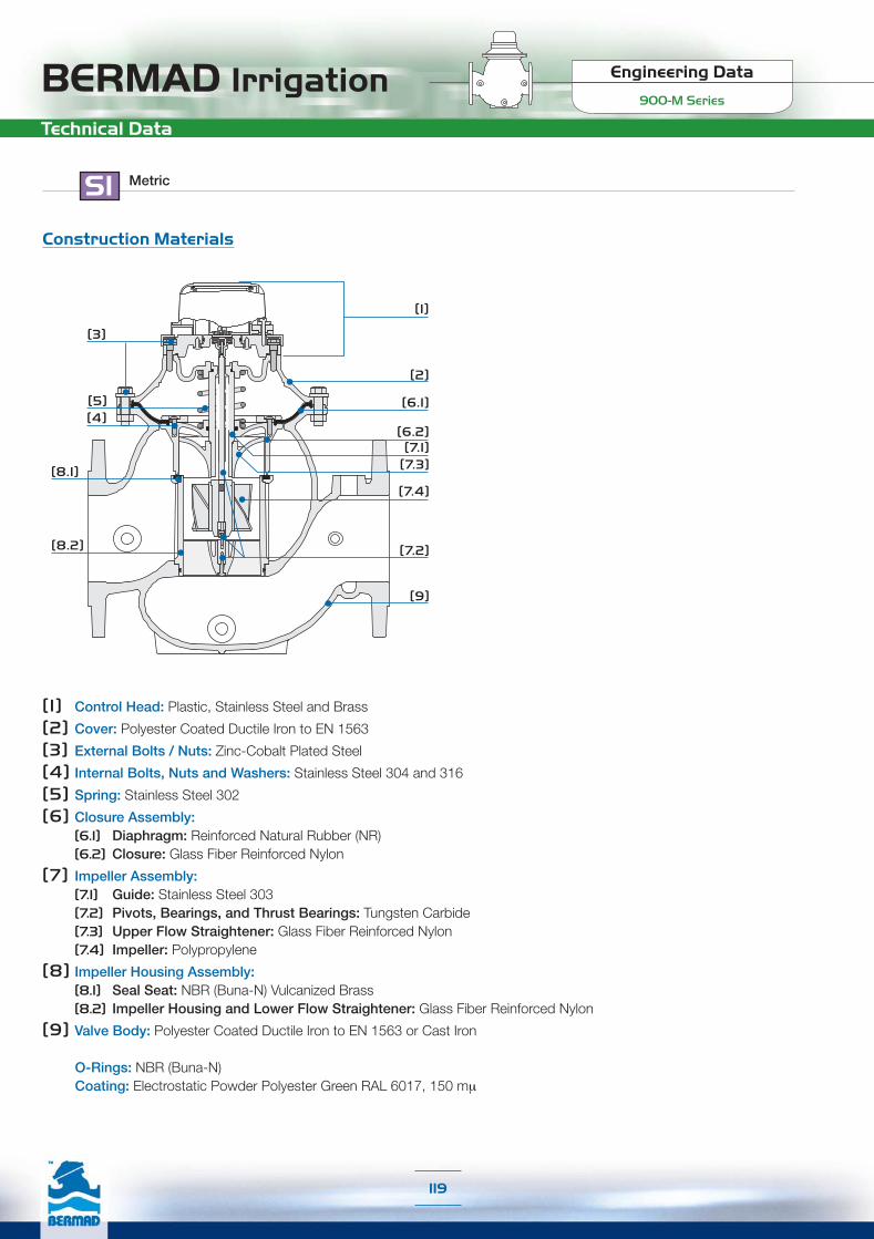
Engineering Data
900-M SeriesBERMAD IrrigationTechnical Data
Construction Materials
SI Metric
[1]
[3]
[6.1]
[6.2][7.1]
[2]
[5][4]
[7.2]
[7.3]
[7.4]
[8.1]
[8.2]
[9]
[1] Control Head: Plastic, Stainless Steel and Brass
[2] Cover: Polyester Coated Ductile Iron to EN 1563
[3] External Bolts / Nuts: Zinc-Cobalt Plated Steel
[4] Internal Bolts, Nuts and Washers: Stainless Steel 304 and 316
[5] Spring: Stainless Steel 302
[6] Closure Assembly:[6.1] Diaphragm: Reinforced Natural Rubber (NR)[6.2] Closure: Glass Fiber Reinforced Nylon
[7] Impeller Assembly:[7.1] Guide: Stainless Steel 303[7.2] Pivots, Bearings, and Thrust Bearings: Tungsten Carbide[7.3] Upper Flow Straightener: Glass Fiber Reinforced Nylon[7.4] Impeller: Polypropylene
[8] Impeller Housing Assembly:[8.1] Seal Seat: NBR (Buna-N) Vulcanized Brass[8.2] Impeller Housing and Lower Flow Straightener: Glass Fiber Reinforced Nylon
[9] Valve Body: Polyester Coated Ductile Iron to EN 1563 or Cast Iron
O-Rings: NBR (Buna-N)Coating: Electrostatic Powder Polyester Green RAL 6017, 150 mµ
119

BERMAD Irrigation Engineering Data
900-M Series
Technical Data
Technical Specifications
Connections DN40 DN50 DN65 DN80R DN80 DN100 DN150 DN200 DN250Threaded G G & A GThreaded (Male) G GFlanged H* G G & A G, A & H G & A G & A GFlange Inlet \ Thread Outlet A H* G H
G = Globe, A = Angle 90°, H=Hydrant (Angle 120°) * Triangle Flange Inlet
Pulse Electric Data:Reed-Switch: Switching voltage: 48 VAC/DC max
Switching current: 0.2A maxSwitching power: 4W max
Opto-Electric: Supply voltage: 5-12 VDCOutput type: complementaryOutput current: 200 mA
Available Patterns, Sizes & End Connections:
Connections Standard:Flanged: ISO 7005-2 (PN10 & 16)
Triangle Flange (DN65 inlet only)Threaded: Rp ISO 7/1 (BSP.P) or NPTPressure Rating: PN16Operating Pressure Ranges:PN10: 0.7-10 barPN16: 0.7-16 barFor lower pressure requirements, consult factoryTemperature: Water up to 50°CPulse Options:
Register Type
Pulse PerSize Range
Reed Switch - Single Reed Switch - Combined
10 liter 100 liter 10 m31 m310 liter +100 liter
100 liter +1 m3
DN40-DN100 ■ ■ ■ ■ ■
DN150-DN250 ■ ■
Opto-Electric Opto-Electric + Reed Switch - Combined
1 liter 10 liter1 liter (Opto) +100 liter (Reed)
1 liter (Opto) +1 m3 (Reed)
10 liter (Opto) +1 m3 (Reed)
10 liter (Opto) +10 m3 (Reed)
■ ■ ■
■ ■ ■
DN40-DN100DN150-DN250
SI Metric
Register Type
Pulse PerSize Range
120
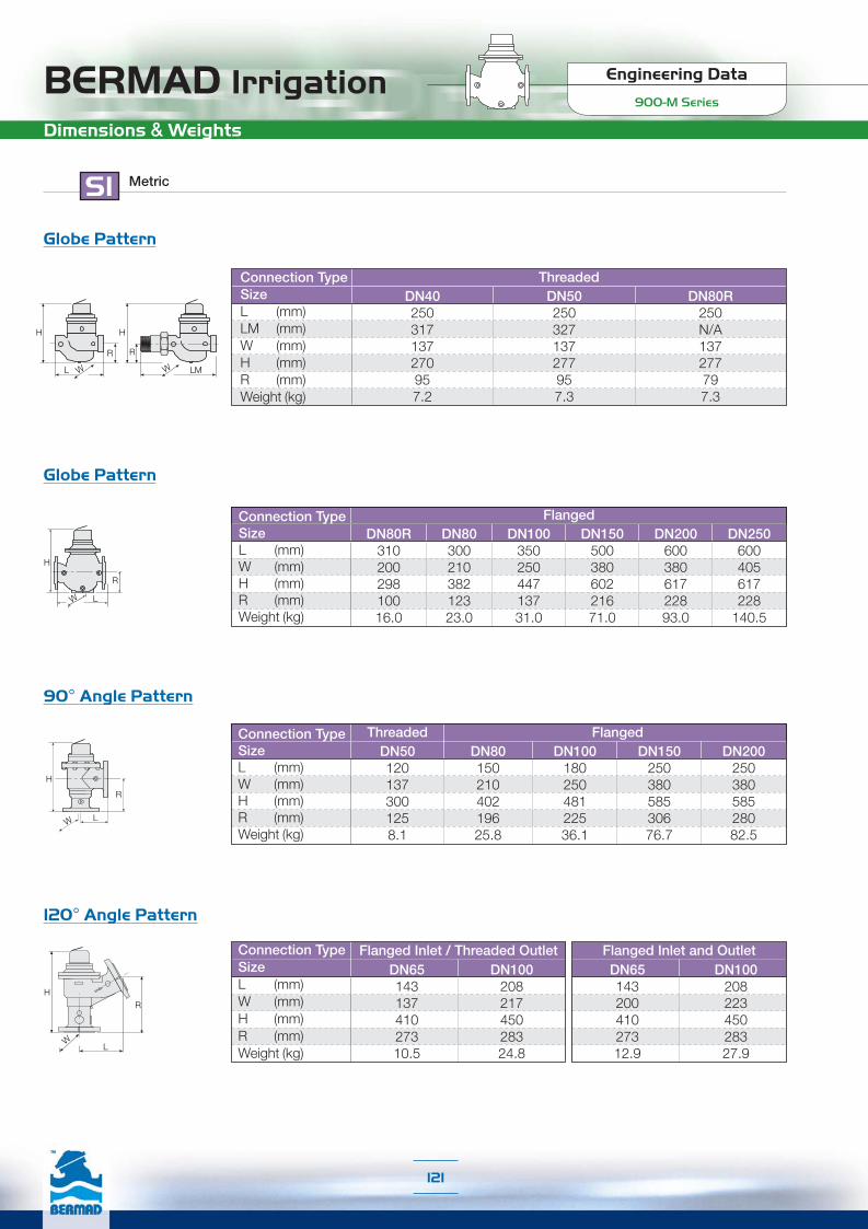
Engineering Data
900-M SeriesBERMAD IrrigationDimensions & Weights
Flow Charts
SI Metric
R
L
H
W
120° Angle Pattern
DN6514320041027312.9
DN10020822345028327.9
Flanged Inlet and OutletDN6514313741027310.5
DN10020821745028324.8
Flanged Inlet / Threaded OutletConnection TypeSizeL (mm)W (mm)H (mm)R (mm)Weight (kg)
R
L
H
W
90° Angle Pattern
R
L
H
W
Globe Pattern
Globe Pattern
R
L
H
W
R
LM
H
W
DN40250317137270957.2
DN50250327137277957.3
DN80R250N/A137277797.3
ThreadedConnection TypeSizeL (mm)LM (mm)W (mm)H (mm)R (mm)Weight (kg)
DN8030021038212323.0
DN20060038061722893.0
DN250600405617228
140.5
DN15050038060221671.0
DN10035025044713731.0
DN80R31020029810016.0
FlangedConnection TypeSizeL (mm)W (mm)H (mm)R (mm)Weight (kg)
Connection TypeSizeL (mm)W (mm)H (mm)R (mm)Weight (kg)
DN501201373001258.1
DN8015021040219625.8
DN15025038058530676.7
DN20025038058528082.5
DN10018025048122536.1
Threaded Flanged
121
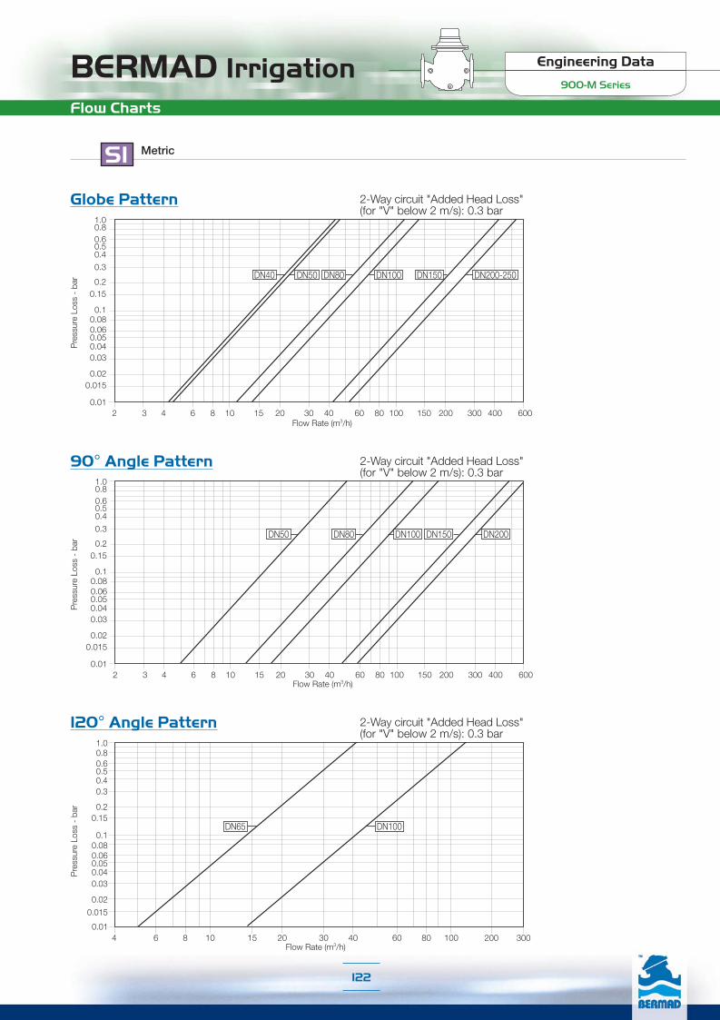
BERMAD Irrigation Engineering Data
900-M Series
Flow Charts
SI Metric
120° Angle Pattern
4 6 8 10 15 20 30 40 60 80 100 200 300
1.00.80.60.50.40.3
0.20.15
0.01
0.10.080.060.050.040.03
0.02
0.015
DN65 DN100
Pre
ssur
e Lo
ss -
bar
Flow Rate (m3/h)
90° Angle Pattern
Flow Rate (m3/h)2 3 4 6 8 10 15 20 30 40 60 80 100 150 200 300 400 600
0.06
1.00.80.60.50.4
0.3
0.20.15
0.01
Pre
ssur
e Lo
ss -
bar
0.10.08
0.050.040.03
0.020.015
DN50 DN80 DN100 DN150 DN200
Globe Pattern
Flow Rate (m3/h)2 3 4 6 8 10 15 20 30 40 60 80 100 150 200 300 400 600
DN40 DN50 DN80 DN100 DN150 DN200-250
0.06
1.00.80.60.50.4
0.3
0.20.15
0.01
Pre
ssur
e Lo
ss -
bar
0.10.08
0.050.040.03
0.020.015
2-Way circuit "Added Head Loss"(for "V" below 2 m/s): 0.3 bar
2-Way circuit "Added Head Loss"(for "V" below 2 m/s): 0.3 bar
2-Way circuit "Added Head Loss"(for "V" below 2 m/s): 0.3 bar
122

Engineering Data
900-M SeriesBERMAD IrrigationFlow Properties
SI Metric
90°AnglePattern
GlobePattern
120°AnglePattern
Size DN40 DN50 DN65 DN80R DN80 DN100 DN150 DN200 DN250Kv 41 46 N/A 50 115 147 430 550 550K 2.4 4.6 N/A 24.7 4.9 7.3 4.3 8.3 20.2
Leq - m 4.8 12.9 N/A 109.7 21.6 42.7 42.9 110.5 337.2Kv N/A 51 N/A N/A 126 180 473 605 N/AK N/A 3.8 N/A N/A 4.0 4.8 3.5 6.8 N/A
Leq - m N/A 10.5 N/A N/A 18.0 28.4 35.5 91.3 N/AKv N/A N/A 51 N/A N/A 147 N/A N/A N/AK N/A N/A 3.8 N/A N/A 7.3 N/A N/A N/A
Leq - m N/A N/A 10.5 N/A N/A 42.7 N/A N/A N/A
Where:Kv = Valve flow coefficient (flow in m3/h at 1bar Diff. Press.)Cv = Valve flow coefficient (flow in gpm at Diff. Press. 1psi)Q = Flow rate (m3/h ; gpm)P = Differential pressure (bar ; psi)
Gf = Liquid specific gravity (Water = 1.0)
Valve flow coefficient, Kv or Cv Kv(Cv)=Q Gf
P
Kv = 0.865 Cv
Where:K = Flow resistance or Head loss coefficient (dimensionless)H = Head loss (m ; feet)
V = Nominal size flow velocity (m/sec ; feet/sec.)g = Acceleration of gravity (9.81 m/sec2 ; 32.18 feet/sec2)
K = H2gV2
Flow resistance or Head loss coefficient,
Equivalent Pipe Length, Leq
Where:Leq= Equivalent nominal pipe length (m ; feet)Lk = Equivalent length coefficient for turbulent flow in clean
commercial steel pipe (SCH 40)D = Nominal pipe diameter (m ; feet)
Note:The Leq values given are for general consideration only.
Leq = Lk·D
Accuracy Table
Q1 Minimum FlowQ2 Transitional FlowQn Nominal Flow ISO 4064-1-1993Q3 Permanent FlowQ4 Maximum Flow (Short Time)Q2/Q1Q3/Q1Class ISO 4064-1-1993
Accuracy
±5%±2%±2%±2%±2%
---
DN40
0.81.31525311.631A
DN50
0.81.31540501.650A
DN65
1.21.92540501.633A
DN80
1.23401001252.583B
DN100
1.84.5601602002.589B
DN150
4101502503132.563B
DN200
6.315.82504005002.563B
DN250
6.315.84004005002.563B
123
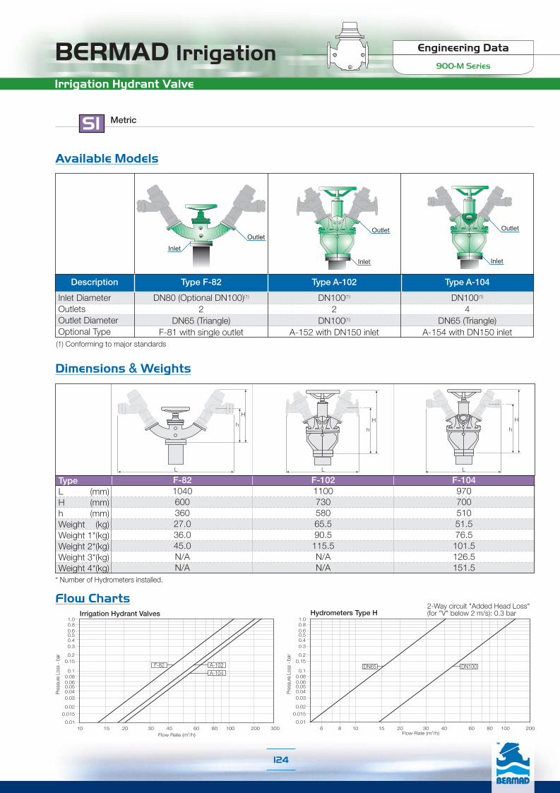
BERMAD Irrigation Engineering Data
900-M Series
Irrigation Hydrant Valve
SI Metric
Inlet DiameterOutletsOutlet DiameterOptional Type
Description Type A-102 Type A-104
DN100(1)
4DN65 (Triangle)
A-154 with DN150 inlet
DN100(1)
2DN100(1)
A-152 with DN150 inlet
DN80 (Optional DN100)(1)
2DN65 (Triangle)
F-81 with single outlet
Type F-82
InletInlet
Outlet
Inlet
Outlet Outlet
Flow ChartsHydrometers Type H
6 8 10 15 20 30 40 60 80 100 200
1.00.80.60.50.40.3
0.20.15
0.01
0.10.080.060.050.040.03
0.02
0.015
Pres
sure
Los
s - b
ar
Flow Rate (m3/h)
DN100DN65
2-Way circuit "Added Head Loss"(for "V" below 2 m/s): 0.3 bar
Flow Rate (m3/h)
1.00.80.60.50.40.3
0.20.15
0.01
0.10.080.060.050.040.03
0.02
0.015
Pres
sure
Los
s - b
ar
Irrigation Hydrant Valves
A-102
A-104
F-82
10 15 20 30 40 60 80 100 200 300
Dimensions & Weights
TypeL (mm)H (mm)h (mm)Weight (kg)Weight 1*(kg)Weight 2*(kg)Weight 3*(kg)Weight 4*(kg)
F-82104060036027.036.045.0N/AN/A
F-102110073058065.590.5115.5N/AN/A
F-10497070051051.576.5101.5126.5151.5
* Number of Hydrometers installed.
H
h
L
H
h
L
H
h
L
Available Models
(1) Conforming to major standards
124

Engineering Data
900-M SeriesBERMAD IrrigationTechnical Data
US English
[1] Control Head: Plastic, Stainless Steel and Brass
[2] Cover: Polyester Coated Ductile Iron to ASTM A536
[3] External Bolts / Nuts: Zinc-Cobalt Plated Steel
[4] Internal Bolts, Nuts and Washers: Stainless Steel 304 and 316
[5] Spring: Stainless Steel 302
[6] Closure Assembly:[6.1] Diaphragm: Reinforced Natural Rubber (NR)[6.2] Closure: Glass Fiber Reinforced Nylon
[7] Impeller Assembly:[7.1] Guide: Stainless Steel 303[7.2] Pivots, Bearings, and Thrust Bearings: Tungsten Carbide[7.3] Upper Flow Straightener: Glass Fiber Reinforced Nylon[7.4] Impeller: Polypropylene
[8] Impeller Housing Assembly:[8.1] Seal Seat: NBR (Buna-N) Vulcanized Brass[8.2] Impeller Housing and Lower Flow Straightener: Glass Fiber
Reinforced Nylon
[9] Valve Body: Polyester Coated Ductile Iron to ASTM A-536 or Cast Iron to ASTM A-126 Class B
O-Rings: NBR (Buna-N)Coating: Electrostatic Powder Polyester Green RAL 6017, 150 mµ
[1]
[3]
[6.1]
[6.2][7.1]
[2]
[5][4]
[7.2]
[7.3]
[7.4]
[8.1]
[8.2]
[9]
Construction Materials
125

BERMAD Irrigation Engineering Data
900-M Series
Technical Data
Pulse Electric Data:Reed-Switch: Switching voltage: 48 VAC/DC max
Switching current: 0.2A maxSwitching power: 4W max
Opto-Electric: Supply voltage: 5-12 VDCOutput type: complementaryOutput current: 200 mA
US English
Technical Specifications
Connections 11/2” 2” 21/2” 3”R 3” 4” 6” 8” 10”Threaded G G & A GThreaded (Male) G GFlanged H* G G & A G, A & H G & A G & A GFlange Inlet \ Thread Outlet A H* G H
G = Globe, A = Angle 90°, H= Hydrant (Angle 120°) * Triangle Flange Inlet
Available Patterns, Sizes & End Connections:
Connections Standard:Flanged: ANSI B16.41 (Cast Iron)
ANSI B16.42 (Ductile Iron)Triangle Flange (21/2” inlet only)
Threaded: NPT or Rp ISO 7/1 (BSP.P)Pressure Rating Classes: Cast Iron - #125; Ductile Iron - #150Operating Pressure Ranges:Class #125: 10-150 psi; Class #150: 10-250 psiFor lower pressure requirements, consult factoryTemperature: Water up to 122°FPulse Options:
11/2”-4”6”-10”
Reed Switch - Single Reed Switch - Combined
1 gallon 10 gallon 1000 gallon100 gallon1 galon +10 gallon
10 galon +100 gallon
■ ■ ■ ■ ■
■ ■ ■
Register Type
Pulse PerSize Range
11/2”-4”
6”-10”
Opto-Electric Opto-Electric + Reed Switch - Combined
0.1gallon
1gallon
0.1 gallon (Opto) +1 gallon (Reed)
1 gallon (Opto) +100 (Reed)
1 gallon (Opto) +1000 (Reed)
0.1 gallon (Opto) +10 gallon (Reed)
■ ■ ■
■ ■ ■
Register Type
Pulse PerSize Range
126

Engineering Data
900-M SeriesBERMAD IrrigationDimensions & Weights
US English
21/2”55/8
77/8
161/8
103/4
28.0
4”83/16
83/4
1711/16
111/8
60.8
Flanged Inlet and Outlet
Globe Pattern
11/2”913/16
1217/16
53/8
105/8
3.15.9
2”913/16
1213/16
53/8
1015/16
33/4
16.1
3”R913/16
N/A53/8
1015/16
31/8
16.1
ThreadedConnection TypeSizeL (inch)LM (inch)W (inch)H (inch)R (inch)Weight (lb)
R
L
H
W
Globe Pattern
3”1113/16
81/4
151/16
413/16
50.7
8”235/8
1415/16
245/16
9202.8
10”235/8
1515/16
245/16
9309.1
6”1911/16
1415/16
2311/16
81/2
154.3
4”133/4
913/16
175/8
53/8
66.1
3”R123/16
77/8
113/4
315/16
35.3
FlangedConnection TypeSizeL (inch)W (inch)H (inch)R (inch)Weight (lb)
R
L
H
W
120° Angle Pattern
21/2”55/8
53/8
161/8
103/4
22.7
4”83/16
89/16
1711/16
111/8
54.0
Flanged Inlet / Threaded OutletConnection TypeSizeL (inch)W (inch)H (inch)R (inch)Weight (lb)
R
L
H
W
90° Angle Pattern
Connection TypeSizeL (inch)W (inch)H (inch)R (inch)Weight (lb)
2”43/4
53/8
1113/16
415/16
17.4
3”515/16
81/4
1513/16
73/4
56.2
6”913/16
1415/16
23121/16
168.4
8”913/16
1415/16
2311
181.2
4”71/16
913/16
1815/16
87/8
78.9
Threaded Flanged
R
L
H
W
R
LM
H
W
127

BERMAD Irrigation Engineering Data
900-M Series
Flow Charts
US English
20.0
0.1
0.2
0.30.4
0.60.81.0
2.0
3.04.0
6.08.0
10.0
Pre
ssur
e Lo
ss -
psi
Flow Rate (gpm)4 6 8 10 20 30 40 60 80 100 200 400 600 1,000 2,000 4,000
21/2” 4”
120° Angle Pattern
20.0
0.1
0.2
0.30.4
0.60.81.0
2.0
3.04.0
6.08.0
10.0
Pre
ssur
e Lo
ss -
psi
4 6 8 10 20 30 40 60 80 100 200 400 600 1,000 2,000 4,000Flow Rate (gpm)
2” 4”3” 8”6”
90° Angle Pattern
Flow Rate (gpm)
Globe Pattern20.0
0.1
0.2
0.30.4
0.60.81.0
2.0
3.04.0
6.08.0
10.0
Pre
ssur
e Lo
ss -
psi
4 6 8 10 20 30 40 60 80 100 200 400 600 1,000 2,000 4,000
11/2” 3” 6”2” 4” 8-10”
2-Way circuit "Added Head Loss"(for "V" below 6.5 f/s): 4.5 psi
2-Way circuit "Added Head Loss"(for "V" below 6.5 f/s): 4.5 psi
2-Way circuit "Added Head Loss"(for "V" below 6.5 f/s): 4.5 psi
128

Engineering Data
900-M SeriesBERMAD Irrigation
90°AnglePattern
GlobePattern
120°AnglePattern
Size 11/2” 2” 21/2” 3”R 3” 4” 6” 8” 10”Cv 47 53 N/A 58 133 170 497 636 636K 2.4 4.6 N/A 24.7 4.9 7.3 4.3 8.3 20.2
Leq - f 15.7 42.2 N/A 359.8 70.8 139.9 140.8 362.5 1106.4Cv N/A 59 N/A N/A 146 208 547 699 N/AK N/A 3.8 N/A N/A 4.0 4.8 3.5 6.8 N/A
Leq - f N/A 34.3 N/A N/A 58.9 93.3 116.3 299.6 N/ACv N/A N/A 59 N/A N/A 170 N/A N/A N/AK N/A N/A 3.8 N/A N/A 7.3 N/A N/A N/A
Leq - f N/A N/A 34.3 N/A N/A 139.9 N/A N/A N/A
Flow Properties
US English
Where:Kv = Valve flow coefficient (flow in m3/h at 1bar Diff. Press.)Cv = Valve flow coefficient (flow in gpm at Diff. Press. 1psi)Q = Flow rate (gpm ; m3/h)P = Differential pressure (psi ; bar)
Gf = Liquid specific gravity (Water = 1.0)
Valve flow coefficient, Cv or Kv Cv(Kv)=Q Gf
P
Cv = 1.155 Kv
Where:K = Flow resistance or Head loss coefficient (dimensionless)H = Head loss (feet ; m)
V = Nominal size flow velocity (feet/sec ; m/sec.)g = Acceleration of gravity (32.18 feet/sec2 ; 9.81 m/sec2 )
K = H2gV2
Flow resistance or Head loss coefficient,
Equivalent Pipe Length, Leq
Where:Leq = Equivalent nominal pipe length (feet ; m)Lk = Equivalent length coefficient for turbulent flow in clean
commercial steel pipe (SCH 40)D = Nominal pipe diameter (feet ; m)
Note:The Leq values given are for general consideration only.Actual Leq may vary somewhat with each of the valve sizes.
Leq = Lk·D
Accuracy Table
Q1 Minimum FlowQ2 Transitional FlowNominal Flow ISO 4064-1-1993Q3 Permanent FlowQ4 Flow Maximum (Short Time)Q2/Q1Q3/Q1Class ISO 4064-1-1993
Accuracy
±5%±2%±2%±2%±2%
---
11/2”3.55.7661101361.631A
2”
3.55.7661762201.650A
21/2”5.38.41101762201.633A
3”
5.313.21764405502.583B
4”
7.919.82647048802.589B
6”
17.644660110013782.563B
8”
27.769.61100176122012.563B
10”
27.769.61761176122012.563B
129
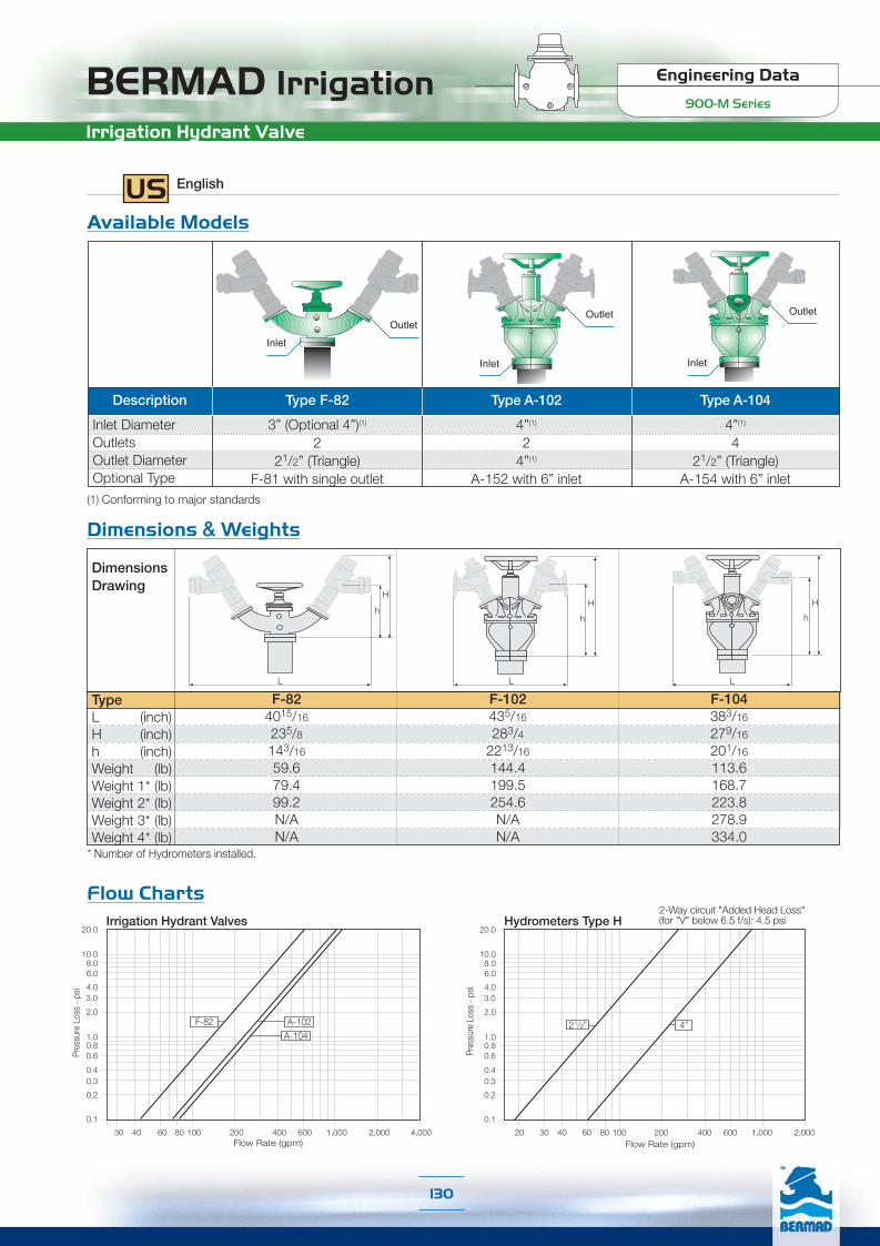
BERMAD Irrigation Engineering Data
900-M Series
Irrigation Hydrant Valve
Dimensions & Weights
Flow Charts
US English
TypeL (inch)H (inch)h (inch)Weight (lb)Weight 1* (lb)Weight 2* (lb)Weight 3* (lb)Weight 4* (lb)
F-824015/16
235/8
143/16
59.679.499.2N/AN/A
F-102435/16
283/4
2213/16
144.4199.5254.6N/AN/A
F-104383/16
279/16
201/16
113.6168.7223.8278.9334.0
* Number of Hydrometers installed.
H
h
L
H
h
L
H
h
L
DimensionsDrawing
30 40 60 80 100 200 400 600 1,000 2,000 4,000
Irrigation Hydrant Valves20.0
0.1
0.2
0.30.4
0.60.81.0
2.0
3.04.0
6.08.0
10.0
Flow Rate (gpm)
A-102F-82
A-104
Pres
sure
Los
s - p
si
Inlet DiameterOutletsOutlet DiameterOptional Type
(1) Conforming to major standards
Description Type A-102 Type A-104
4”(1)
421/2” (Triangle)
A-154 with 6” inlet
4”(1)
24”(1)
A-152 with 6” inlet
3” (Optional 4”)(1)
221/2” (Triangle)
F-81 with single outlet
Type F-82
InletInlet
Outlet
Inlet
Outlet Outlet
Available Models
Hydrometers Type H20.0
0.1
0.2
0.30.4
0.60.81.0
2.0
3.04.0
6.08.0
10.0
Pres
sure
Los
s - p
si
Flow Rate (gpm)
21/2” 4”
2-Way circuit "Added Head Loss"(for "V" below 6.5 f/s): 4.5 psi
20 30 40 60 80 100 200 400 600 1,000 2,000
130

Engineering DataIR-900-D Series

BERMAD Irrigation Engineering Data
900-D Series
Product Parts Features
[1]
[2]
[2.1]
[3]
[4]
[5]
[6.1]
[6.2]
[6.3]
[7.1]
[9]
[8]
[9.1]
[9.1]
[6]
[7][7.2]
[1] Setting KnobEasy "Push & Set" batch pre-setting
[2] Control HeadIncludes: Flow totaling counter, visual flow rate indicator, non-computerizeddose control and pulse output for computerized data capture and control.
[2.1] Shut-Off Pilot: Spring loaded pilot which is manually preset to divert linepressure into the AMV control chamber and automatically switches todrain pressure out of the control chamber.Optional: ❑ Sequential Shut-Off Pilot
❑ Shut-Off Pilot with Pump Shut-Off Electrical Switch.
[3] Valve CoverLocates, centralizes and fastens diaphragm, spring, and impeller assemblyensuring smooth and accurate performance. Simple and light constructionenables quick in-line inspection and service.
[4] Auxiliary Closing SpringOne single spring fully meets valve requirements for operating pressure range,ensuring low opening pressure and secured closing.
[5] Closure AssemblyCombining a rugged radial disk harnessed to a flexible fiber reinforced diaphragm.The fully guided closure assembly and the carefully balanced and peripherallysupported diaphragm prevent distortion and protect the elastomer, resultingin long-life and controlled actuation even under harsh conditions. One diaphragmand spring fully meet the valve's operating pressure range requirements.
[6] Impeller Assembly[6.1] Guide – Carries the transmission shaft, guides the closure assembly,
and centralizes and tightens all internal parts.
[6.2] Upper Flow Straightener – Tightens the seal seat in place, straightensoutlet flow, and creates mushroom-shaped flow.
[6.3] Impeller – Woltman-type impeller with tungsten carbide shaft tips and bearings for high, long-term accuracy and negligible wear
[7] Impeller Housing[7.1] Lower Flow Straightener – Straightens inlet flow, eliminating the need for
straight upstream pipe required in standard water meters
[7.2] Seal Seat – Metal ring vulcanized with elastomeric seal, raised and remotefrom valve body to prevent cavitation damage.
[8] Integrated Calibration DeviceEnables recalibration instead of renovation when the recommended standardaccuracy period has elapsed (The Calibration Device is stamped closed witha metal seal)
[9] Wide BodyHydro-dynamically designed for efficient flow with minimal pressure loss andexcellent resistance to cavitation.
[9.1] End Connections conform to pressure ratings and standards: ISO, ANSI,JIS, BS, and others.
132
For spare parts ordering, Please use BERMAD “Spare Parts Ordering Guide”

Engineering Data
900-D SeriesBERMAD IrrigationTechnical Data
Construction Materials
[1] Control Head: Plastic, Stainless Steel and Brass
[2] Shut-Off Pilot: Nylon, Stainless Steel & NBR (Buna-N)
[3] Cover: Polyester Coated Ductile Iron to EN 1563
[4] External Bolts / Nuts: Zinc-Cobalt Plated Steel
[5] Internal Bolts, Nuts and Washers: Stainless Steel 304 and 316
[6] Spring: Stainless Steel 302
[7] Closure Assembly:[7.1] Diaphragm: Reinforced Natural Rubber (NR)[7.2] Closure: Glass Fiber Reinforced Nylon
[8] Impeller Assembly:[8.1] Guide: Stainless Steel 303[8.2] Pivots, Bearings, and Thrust Bearings: Tungsten Carbide[8.3] Upper Flow Straightener: Glass Fiber Reinforced Nylon[8.4] Impeller: Polypropylene
[9] Impeller Housing Assembly:[9.1] Seal Seat: NBR (Buna-N) Vulcanized Brass[9.2] Impeller Housing and Lower Flow Straightener: Glass Fiber Reinforced Nylon
[10]Valve Body: Polyester Coated Ductile Iron to EN 1563 or Cast IronO-Rings: NBR (Buna-N)Coating: Electrostatic Powder Polyester Green RAL 6017, 150 mµ
Pulse Options:For Dials 3.8 through 2,100: 1 Pulse per 1 m3
For Dials 3,500 through 21,000: 1 Pulse per 10 m3
Pulse Electrical Data:Switching Voltage: 48 VAC/DC max.Switching Current: 0.2A max.Switching Power: 4W max.
SI Metric
1 2 3 4 5 [1]
[4]
[7.1]
[7.2][8.1]
[2]
[3]
[6][5]
[8.2]
[8.3]
[8.4][9.1]
[9.2]
[10]
Technical Specifications
Connections DN40 DN50 DN65 DN80R DN80 DN100 DN150 DN200 DN250Threaded G G & A GThreaded (Male) G GFlanged H* G G & A G, A & H G & A G & A GFlange Inlet \ Thread Outlet A H* G H
G = Globe, A = Angle 90°, H= Hydrant (Angle 120°) * Triangle Flange Inlet
Available Patterns, Sizes & End Connections:
Connections Standard:Flanged: ISO 7005-2 (PN10 & 16)Triangle Flange (DN65 inlet only)Threaded: Rp ISO 7/1 (PSP.P) or NPTPressure Ratings:PN10 (Plastic Primary Gear Cover)PN16 (Metal Primary Gear Cover)
Operating Pressure Ranges:PN10: 0.7-10 barPN16: 0.7-16 barFor lower pressure requirements, consult factoryTemperature: Water up to 50°C
Dial Capacity (m3) 3.8 12 40 80 120 150 200 350 600 800 1,200 2,100 3,500 6,000 8,000 12,000 21,000Graduation (m3) 0.1 0.2 1 1 2 2 5 10 10 10 20 50 100 100 100 200 500DN40-DN80DN100-DN250
■ ■ ■ ■ ■ ■ ■ ■ ■ ■ ■ ■
■ ■ ■ ■ ■ ■ ■ ■ ■ ■ ■ ■ ■ ■
Dial Options
133
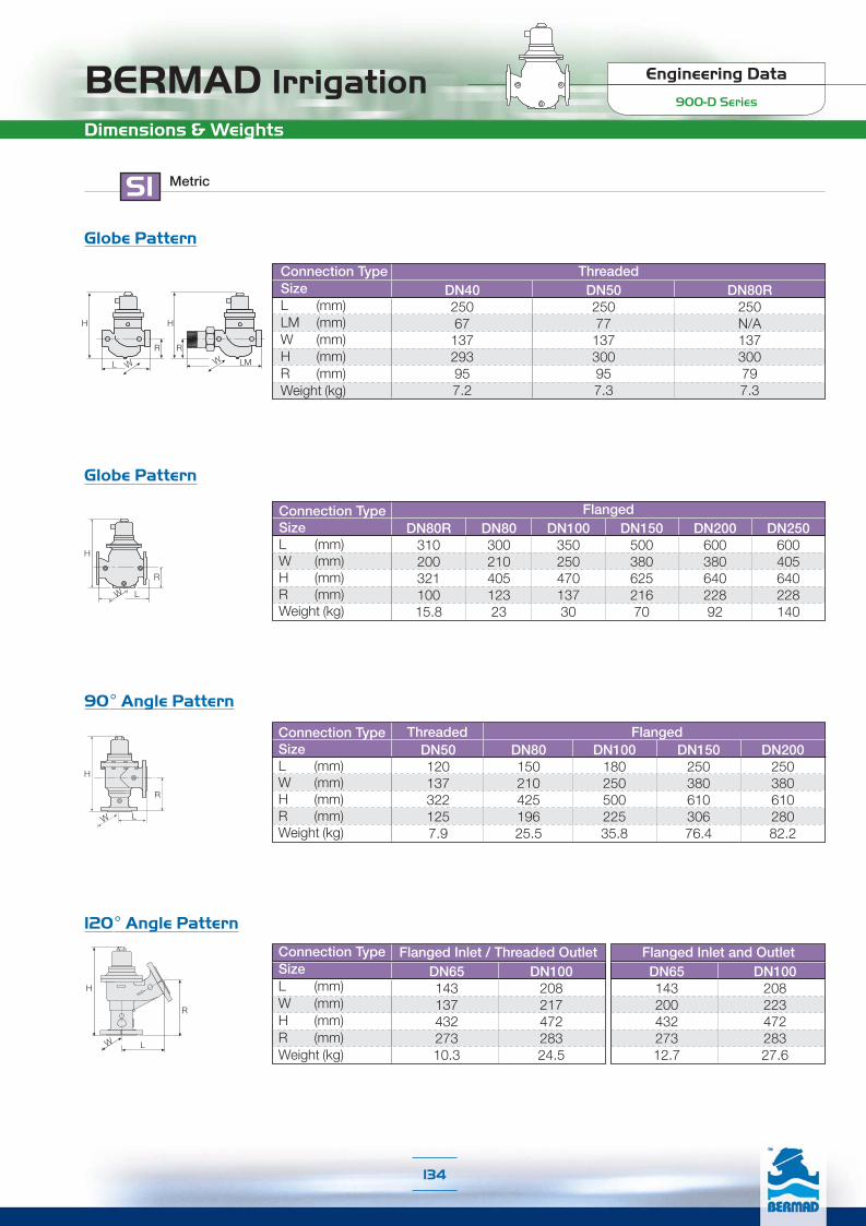
BERMAD Irrigation Engineering Data
900-D Series
Dimensions & Weights
SI Metric
Globe Pattern
DN4025067137293957.2
DN5025077137300957.3
DN80R250N/A137300797.3
ThreadedConnection TypeSizeL (mm)LM (mm)W (mm)H (mm)R (mm)Weight (kg)
R
L
H
W
Globe Pattern
DN8030021040512323
DN20060038064022892
DN250600405640228140
DN15050038062521670
DN10035025047013730
DN80R31020032110015.8
FlangedConnection TypeSizeL (mm)W (mm)H (mm)R (mm)Weight (kg)
90° Angle Pattern
R
L
H
W
Connection TypeSizeL (mm)W (mm)H (mm)R (mm)Weight (kg)
DN501201373221257.9
DN8015021042519625.5
DN15025038061030676.4
DN20025038061028082.2
DN10018025050022535.8
Threaded Flanged
120° Angle Pattern
R
L
H
W
DN6514320043227312.7
DN10020822347228327.6
Flanged Inlet and OutletDN6514313743227310.3
DN10020821747228324.5
Flanged Inlet / Threaded OutletConnection TypeSizeL (mm)W (mm)H (mm)R (mm)Weight (kg)
R
L
H
W
R
LM
H
W
134

Engineering Data
900-D SeriesBERMAD Irrigation
SI Metric
120° Angle Pattern
4 6 8 10 15 20 30 40 60 80 100 200 300
1.00.80.60.50.40.3
0.20.15
0.01
0.10.080.060.050.040.03
0.02
0.015
DN65 DN100
Pre
ssur
e Lo
ss -
bar
Flow Rate (m3/h)
Globe Pattern
Flow Rate (m3/h)2 3 4 6 8 10 15 20 30 40 60 80 100 150 200 300 400 600
DN40 DN50 DN80 DN100 DN150 DN200-250
0.06
1.00.80.60.50.4
0.3
0.20.15
0.01
Pre
ssur
e Lo
ss -
bar
0.10.08
0.050.040.03
0.020.015
2-Way circuit "Added Head Loss"(for "V" below 2 m/s): 0.3 bar
2-Way circuit "Added Head Loss"(for "V" below 2 m/s): 0.3 bar
90° Angle Pattern
Flow Rate (m3/h)2 3 4 6 8 10 15 20 30 40 60 80 100 150 200 300 400 600
0.06
1.00.80.60.50.4
0.3
0.20.15
0.01
Pre
ssur
e Lo
ss -
bar
0.10.08
0.050.040.03
0.020.015
DN50 DN80 DN100 DN150 DN200
2-Way circuit "Added Head Loss"(for "V" below 2 m/s): 0.3 bar
Flow Chart
135

BERMAD Irrigation Engineering Data
900-D Series
Flow Properties
Where:Kv = Valve flow coefficient (flow in m3/h at 1bar Diff. Press.)Cv = Valve flow coefficient (flow in gpm at Diff. Press. 1psi)Q = Flow rate (m3/h ; gpm)P = Differential pressure (bar ; psi)
Gf = Liquid specific gravity (Water = 1.0)
Valve flow coefficient, Kv or Cv Kv(Cv)=Q Gf
P
Kv = 0.865 Cv
Where:K = Flow resistance or Head loss coefficient (dimensionless)H = Head loss (m ; feet)
V = Nominal size flow velocity (m/sec ; feet/sec.)g = Acceleration of gravity (9.81 m/sec2 ; 32.18 feet/sec2)
K = H2gV2
Flow resistance or Head loss coefficient,
Equivalent Pipe Length, Leq
Where:Leq= Equivalent nominal pipe length (m ; feet)Lk = Equivalent length coefficient for turbulent flow in clean
commercial steel pipe (SCH 40)D = Nominal pipe diameter (m ; feet)
Note:The Leq values given are for general consideration only.
Leq = Lk·D
Accuracy Table
SI Metric
90°AnglePattern
GlobePattern
120°AnglePattern
Size DN40 DN50 DN65 DN80R DN80 DN100 DN150 DN200 DN250Kv 41 46 N/A 50 115 147 430 550 550K 2.4 4.6 N/A 24.7 4.9 7.3 4.3 8.3 20.2
Leq - m 4.8 12.9 N/A 109.7 21.6 42.7 42.9 110.5 337.2Kv N/A 51 N/A N/A 126 180 473 605 N/AK N/A 3.8 N/A N/A 4.0 4.8 3.5 6.8 N/A
Leq - m N/A 10.5 N/A N/A 18 28.4 35.5 91.3 N/AKv N/A N/A 51 N/A N/A 147 N/A N/A N/AK N/A N/A 3.8 N/A N/A 7.3 N/A N/A N/A
Leq - m N/A N/A 10.5 N/A N/A 42.7 N/A N/A N/A
Flow Rate (m3)Q1 Minimum FlowQD Safe Closing (AMV)Q2 Transitional FlowQn Nominal Flow ISO 4064-1-1993Q3 Permanent FlowQ4 Maximum Flow (Short Time)Q2/Q1Q3/Q1Class ISO 4064-1-1993
Accuracy
±5%±5%±2%±2%±2%±2%
---
DN40
0.81.51.31525311.631A
DN50
0.82
1.31540501.650A
DN65
1.22
1.92540501.633A
DN80
1.23.23401001252.583B
DN100
1.84.84.5601602002.589B
DN150
410101502503132.563B
DN200
6.312
15.82504005002.563B
DN250
6.312
15.84004005002.563B
136
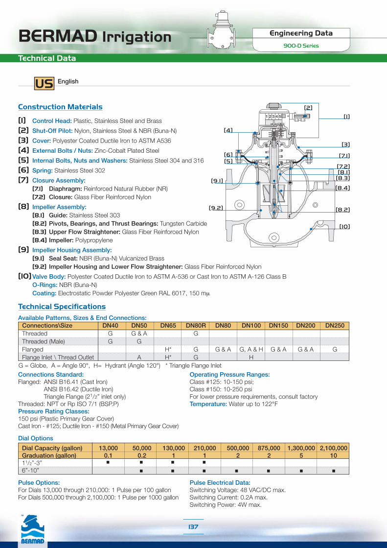
Engineering Data
900-D SeriesBERMAD IrrigationTechnical Data
Pulse Options:For Dials 13,000 through 210,000: 1 Pulse per 100 gallonFor Dials 500,000 through 2,100,000: 1 Pulse per 1000 gallon
Pulse Electrical Data:Switching Voltage: 48 VAC/DC max.Switching Current: 0.2A max.Switching Power: 4W max.
Construction Materials
[1] Control Head: Plastic, Stainless Steel and Brass
[2] Shut-Off Pilot: Nylon, Stainless Steel & NBR (Buna-N)
[3] Cover: Polyester Coated Ductile Iron to ASTM A536
[4] External Bolts / Nuts: Zinc-Cobalt Plated Steel
[5] Internal Bolts, Nuts and Washers: Stainless Steel 304 and 316
[6] Spring: Stainless Steel 302
[7] Closure Assembly:[7.1] Diaphragm: Reinforced Natural Rubber (NR)[7.2] Closure: Glass Fiber Reinforced Nylon
[8] Impeller Assembly:[8.1] Guide: Stainless Steel 303[8.2] Pivots, Bearings, and Thrust Bearings: Tungsten Carbide[8.3] Upper Flow Straightener: Glass Fiber Reinforced Nylon[8.4] Impeller: Polypropylene
[9] Impeller Housing Assembly:[9.1] Seal Seat: NBR (Buna-N) Vulcanized Brass[9.2] Impeller Housing and Lower Flow Straightener: Glass Fiber Reinforced Nylon
[10]Valve Body: Polyester Coated Ductile Iron to ASTM A-536 or Cast Iron to ASTM A-126 Class BO-Rings: NBR (Buna-N)Coating: Electrostatic Powder Polyester Green RAL 6017, 150 mµ
1 2 3 4 5 [1]
[4]
[7.1]
[7.2][8.1]
[2]
[3]
[6][5]
[8.2]
[8.3]
[8.4][9.1]
[9.2]
[10]
US English
Technical Specifications
Connections\Size DN40 DN50 DN65 DN80R DN80 DN100 DN150 DN200 DN250Threaded G G & A GThreaded (Male) G GFlanged H* G G & A G, A & H G & A G & A GFlange Inlet \ Thread Outlet A H* G H
G = Globe, A = Angle 90°, H= Hydrant (Angle 120°) * Triangle Flange Inlet
Available Patterns, Sizes & End Connections:
Connections Standard:Flanged: ANSI B16.41 (Cast Iron)
ANSI B16.42 (Ductile Iron)Triangle Flange (21/2” inlet only)
Threaded: NPT or Rp ISO 7/1 (BSP.P)Pressure Rating Classes:150 psi (Plastic Primary Gear Cover)Cast Iron - #125; Ductile Iron - #150 (Metal Primary Gear Cover)
Operating Pressure Ranges:Class #125: 10-150 psi;Class #150: 10-250 psiFor lower pressure requirements, consult factoryTemperature: Water up to 122°F
Dial Options
■ ■ ■ ■
■ ■ ■ ■ ■ ■ ■
Dial Capacity (gallon) 13,000 50,000 130,000 210,000 500,000 875,000 1,300,000 2,100,000Graduation (gallon) 0.1 0.2 1 1 2 2 5 1011/2”-3”6”-10”
137

BERMAD Irrigation Engineering Data
900-D Series
Dimensions & Weights
US English
Globe Pattern
11/2”913/16
25/8
53/8
119/16
33/4
15.9
2”913/16
353/8
1113/16
33/4
16.1
3”R913/16
N/A53/8
1113/16
31/8
16.1
ThreadedConnection TypeSizeL (inch)LM (inch)W (inch)H (inch)R (inch)Weight (kg)
R
L
H
W
Globe Pattern
3”1113/16
81/4
1515/16
413/16
50.7
8”235/8
1415/16
253/16
9202.8
10”235/8
1515/16
253/16
9309.1
6”1911/16
1415/16
245/8
81/2
154.3
4”133/4
913/16
181/2
53/8
66.1
3”R123/16
77/8
125/8
315/16
35.3
FlangedConnection TypeSizeL (inch)W (inch)H (inch)R (inch)Weight (kg)
90° Angle Pattern
R
L
H
W
Connection TypeSizeL (inch)W (inch)H (inch)R (inch)Weight (kg)
2”43/4
53/8
1211/16
415/16
17.4
3”515/16
81/4
163/4
73/4
56.2
6”913/16
1415/16
24121/16
168.4
8”913/16
1415/16
2411
181.2
4”71/16
913/16
1911/16
87/8
78.9
Threaded Flanged
120° Angle Pattern
R
L
H
W
21/2”55/8
53/8
17103/4
22.7
4”83/16
89/16
189/16
111/8
54.0
21/2”55/8
77/8
17103/4
28.0
4”83/16
83/4
189/16
111/8
60.8
Flanged Inlet / Threaded Outlet Flanged Inlet and OutletConnection TypeSizeL (inch)W (inch)H (inch)R (inch)Weight (lb)
R
L
H
W
H
W LM
R
138
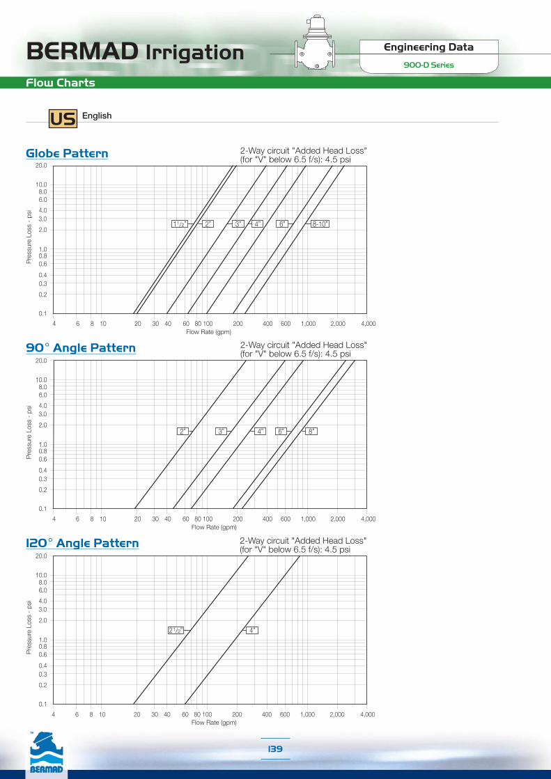
Engineering Data
900-D SeriesBERMAD IrrigationFlow Charts
US English
20.0
0.1
0.2
0.30.4
0.60.81.0
2.0
3.04.0
6.08.0
10.0
Pre
ssur
e Lo
ss -
psi
Flow Rate (gpm)4 6 8 10 20 30 40 60 80 100 200 400 600 1,000 2,000 4,000
21/2” 4”
120° Angle Pattern
20.0
0.1
0.2
0.30.4
0.60.81.0
2.0
3.04.0
6.08.0
10.0
Pre
ssur
e Lo
ss -
psi
4 6 8 10 20 30 40 60 80 100 200 400 600 1,000 2,000 4,000Flow Rate (gpm)
2” 4”3” 8”6”
90° Angle Pattern
Flow Rate (gpm)
Globe Pattern20.0
0.1
0.2
0.30.4
0.60.81.0
2.0
3.04.0
6.08.0
10.0
Pre
ssur
e Lo
ss -
psi
4 6 8 10 20 30 40 60 80 100 200 400 600 1,000 2,000 4,000
11/2” 3” 6”2” 4” 8-10”
2-Way circuit "Added Head Loss"(for "V" below 6.5 f/s): 4.5 psi
2-Way circuit "Added Head Loss"(for "V" below 6.5 f/s): 4.5 psi
2-Way circuit "Added Head Loss"(for "V" below 6.5 f/s): 4.5 psi
139

BERMAD Irrigation Engineering Data
900-D Series
Flow Properties
Where:Kv = Valve flow coefficient (flow in m3/h at 1bar Diff. Press.)Cv = Valve flow coefficient (flow in gpm at Diff. Press. 1psi)Q = Flow rate (gpm ; m3/h)P = Differential pressure (psi ; bar)
Gf = Liquid specific gravity (Water = 1.0)
Valve flow coefficient, Cv or Kv Cv(Kv)=Q Gf
P
Cv = 1.155 Kv
Where:K = Flow resistance or Head loss coefficient (dimensionless)H = Head loss (feet ; m)
V = Nominal size flow velocity (feet/sec ; m/sec.)g = Acceleration of gravity (32.18 feet/sec2 ; 9.81 m/sec2 )
K = H2gV2
Flow resistance or Head loss coefficient,
Equivalent Pipe Length, Leq
Where:Leq= Equivalent nominal pipe length (feet ; m)Lk = Equivalent length coefficient for turbulent flow in clean
commercial steel pipe (SCH 40)D = Nominal pipe diameter (feet ; m)
Note:The Leq values given are for general consideration only.
Leq = Lk·D
US English
90°AnglePattern
GlobePattern
120°AnglePattern
Size 11/2” 2” 21/2” 3”R 3” 4” 6” 8” 10”Cv 47 53 N/A 58 133 170 497 636 636K 2.4 4.6 N/A 24.7 4.9 7.3 4.3 8.3 20.2
Leq - f 15.7 42.2 N/A 359.8 70.8 139.9 140.8 362.5 1106.4Cv N/A 59 N/A N/A 146 208 547 699 N/AK N/A 3.8 N/A N/A 4.0 4.8 3.5 6.8 N/A
Leq - f N/A 34.3 N/A N/A 58.9 93.3 116.3 299.6 N/ACv N/A N/A 59 N/A N/A 170 N/A N/A N/AK N/A N/A 3.8 N/A N/A 7.3 N/A N/A N/A
Leq - f N/A N/A 34.3 N/A N/A 139.9 N/A N/A N/A
Accuracy Table
Q1 Minimum FlowQD Safe Closing (AMV)Q2 Transitional FlowQn Nominal Flow ISO 4064-1-1993Q3 Permanent FlowQ4 Maximum Flow (Short Time)Q2/Q1Q3/Q1Class ISO 4064-1-1993
Accuracy
±5%±5%±2%±2%±2%±2%
---
11/2”3.56.65.7441101361.631A
2”
3.58.85.7661762201.650A
21/2”5.38.88.41101762201.633A
3”
5.314.113.21764405502.583B
4”
7.921.119.82647048802.5 89B
6”
17.64444660110013782.563B
8”
27.752.869.61100176122012.563B
10”
27.752.869.61761176122012.563B
140
Engineering DataWW-700 Series
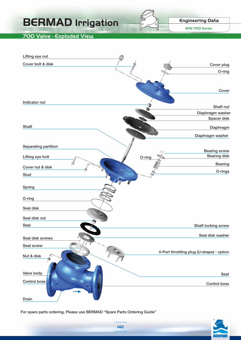
BERMAD Irrigation Engineering Data
WW-700 Series
For spare parts ordering, Please use BERMAD “Spare Parts Ordering Guide”
Lifting eye nut
Cover bolt & disk
Indicator nutShaft nut
Diaphragm washer
Diaphragm
Spacer disk
Shaft
Cover nut & disk
Spring
O-ring
Seal disk
Seal disk nut
Shaft locking screwSeal
Seal disk washer
Seat screw
SeatValve body
Control boss
Drain
Cover plug
O-ring
Cover
Bearing screw
V-Port throttling plug (U-shape) - option
Control boss
Bearing diskO-ring
Bearing
O-rings
Diaphragm washer
Separating partition
Lifting eye bolt
Stud
Seal disk screws
Nut & disk
700 Valve - Exploded View
142

Engineering Data
WW-700 SeriesBERMAD IrrigationTechnical Specifications
Available Sizes & Patterns11/2” - 20” - Y Pattern11/2” - 18” - Angle24” - 32” - Globe
Connection StandardFlanged: ANSI B16.42 (Ductile Iron)Threaded: NPT or BSP (11/2” -3”)
Water TemperatureUp to 180ºF
Working pressureClass #150: 250 psiClass #300: 400 psi
Standard Materials❑ Main valve body and cover
Ductile Iron to ASTM A-536❑ Main valve internals
Stainless Steel, Bronze & Epoxy coated Steel❑ Control Trim
Brass, Bronze accessoriesStainless Steel 316 fittings & tubingor forged Brass fittings & Copper tubing
❑ ElastomersNBR
❑ CoatingBlue fusion bonded Epoxy
Optional Materials❑ Main valve body and cover
Carbon Steel to ASTM A-216-WCBStainless Steel 316 to ASTM A-743 CF8MNickel Aluminum Bronze to ASTM B-148 C 95800Other materials on request
❑ Control TrimStainless Steel 316, Nickel Aluminum Bronze,Hastalloy C-276 accessoriesMonel fittings & tubing
❑ ElastomersEPDMFPM
US 700 English
Available Sizes & PatternsDN 40 - DN 500 - Y PatternDN 40 - DN 450 - AngleDN 600 - DN 800 - Globe
Connection StandardFlanged: ISO 7005-2 (ISO 10, 16 & 25)Threaded: BSP (Rp ISO 7/1) or NPT (DN 40 - DN 80)
Water TemperatureUp to 80ºC
Working pressureISO PN 16: 16 barISO PN 25: 25 bar
Standard Materials❑ Main valve body and cover
Ductile Iron to EN 1563❑ Main valve internals
Stainless Steel, Bronze & Epoxy coated Steel❑ Control Trim
Brass, Bronze accessoriesStainless Steel 316 fittings & tubingor forged Brass fittings & Copper tubing
❑ ElastomersNBR
❑ CoatingBlue fusion bonded Epoxy
Optional Materials❑ Main valve body and cover
Carbon Steel to EN 10083-1Stainless Steel 316 to EN 10088-1Nickel Aluminum Bronze to BS-EN 1400 AB-2Other materials on request
❑ Control TrimStainless Steel 316, Nickel Aluminum Bronze,Hastalloy C-276 accessoriesMonel fittings & tubing
❑ ElastomersEPDMFPM
SI 700 Metric
143

BERMAD Irrigation Engineering Data
WW-700 Series
Angle Pattern
W
H
h
LR
4012415578852279.5124165788522711
50124155838522710124165858522711.5
6514917895109251121491859510925113.5
8015220010010228121.515920710510928723
1001902221151273423520025012713535041
1502253201431524417123432015916545481
200265390172203545118277390191216558138
250320480204219633205336480223236649233
300396550248273777350415550261294796390
350400550264279781370419550293299801425
40045074029936910828004677403253861099855
45045074032037010828204677403583861099870
ISO
PN 10
; 16
ISO
PN 20
; 25
mmLWRhH
Weight (Kg)LWRhH
Weight (Kg)
Angle Pattern
H
LR
h
W
5012112240832255.5
65140122481022427
801591635511529415
BSP
; NPT
mmLWRhH
Weight (Kg)
Threaded
Flanged
Y Pattern
H
h
L
W
40205155782399.12051557823910
502101658324410.62101658324412.2
6522217895257132221859525715
802502001003052226420710531425
1003202231153663733525012737843
1504153201434927543332015950885
200500390172584125524390191602146
250605480204724217637480223742245
300725550242840370762550261859410
350733550268866381767570295893434
400990740300110884610247403251133900
4501000740319112794510307403571165967
5001100740358116796211367503891197986
ISO
PN 10
; 16
ISO
PN 20
; 25
mmLWhH
Weight (Kg)LWhH
Weight (Kg)
SI 700 Metric
Length according to EN 558-1
W
L
H
h
Globe Pattern 60014501250470196532501500125047019653500
70016501250490198537001650125049019853700
75017501250520201539001750125052020153900
80018501250553204841001850125055320484100
ISO
PN 10
; 16
ISO
PN 20
; 25
mmLWhH
Weight (Kg)LWhH
Weight (Kg)
Y Pattern
L
W
H
BSP
; NPT
h
40155122
402015.5
50155122
402025.5
65212122
482098
80250163
5626417
mmLW
hH
Weight (Kg)
Y Pattern - Length according to EN 558-1DNLWhH
Weight (Kg)LWhH
Weight (Kg)
5023016582.52449.723016582.52449.7
803102001003052131020010030521
1003502351183693135023511836931
1504803201505007048032015050070
200600390180592115600390180592115
250730480213733198730480213733198
300850550243841337850550243841337
Dimensions & Weights
144

Engineering Data
WW-700 SeriesBERMAD Irrigation
Angle Pattern
W
H
h
LR
4012415578852279.5124165788522711
50124155838522710124165858522711.5
6514917895109251121491859510925113.5
8015220010010228121.515920710510928723
1001902221151273423520025012713535041
1502253201431524417123432015916545481
200265390172203545118277390191216558138
250320480204219633205336480223236649233
300396550248273777350415550261294796390
350400550264279781370419550293299801425
40045074029936910828004677403253861099855
45045074032037010828204677403583861099870
PN
10
; 16
PN
25
DNLWRhH
Weight (Kg)LWRhH
Weight (Kg)
Angle Pattern
H
LR
h
W
5012112240832255.5
65140122481022427
801591635511529415
BS
P ;
NP
T
DNLWRhH
Weight (Kg)
Y Pattern
L
W
H
Threaded
BS
P ;
NP
T
DNLW
hH
Weight (Kg)
h
40155122
402015.5
50155122
402025.5
65212122
482098
80250163
5626417
Dimensions & Weights
145
Flanged
Y Pattern
H
h
L
W
5023016582.52449.723016582.52449.7
803102001003052131020010030521
1003502351183693135023511836931
1504803201505007048032015050070
200600390180592115600390180592115
250730480213733198730480213733198
300850550243841337850550243841337
PN
10
; 16
PN
25
DNL*WhH
Weight (Kg)L*WhH
Weight (Kg)
* Length according to EN 558-1.
W
L
H
h
G Pattern 60014501250470196532501500125047019653500
70016501250490198537001650125049019853700
75017501250520201539001750125052020153900
80018501250553204841001850125055320484100
PN
10
; 16
PN
25
DNL*WhH
Weight (Kg)LWhH
Weight (Kg)
40205155782399.12051557823910
6522219095257132221909525715
350733550268866381767570295893434
400990740300110884610247403251133900
4501000740319112794510307403571165967
5001100740358116796211367503891197986
DNLWhH
Weight (Kg)LWhH
Weight (Kg)
502101658324410.62101658324412.2
802502001003052226421010531425
1003202291153663733525412737843
1504153201434927543332015950885
200500390172584125524390191602146
250605480204724217637480223742245
300725550242840370762550261859410
On request (Y Pattern)
* Length according to EN 558-1for DN 50, 80, 100, 150, 200, 250 & 300.
SI 700 Metric European Standard (EN 558-1)
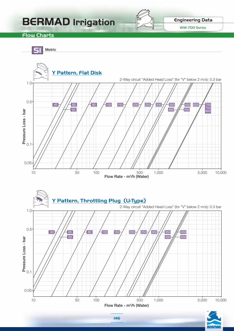
BERMAD Irrigation Engineering Data
WW-700 Series
SI Metric
Y Pattern, Throttling Plug (U-Type)
Flow Rate - m3/h (Water)
Pre
ssur
e Lo
ss -
bar
0.05
0.1
1.0
10 100 1,000 10,000
0.5
50 500 5,000
500
40 65
50
80 100 150 200 250 300 350 450
400
Y Pattern, Flat Disk
Pre
ssur
e Lo
ss -
bar 500
100 150 200 250 300 350 450 600 700750800400
65
50
8040
Flow Rate - m3/h (Water)
0.1
1.0
10 100 1,000 10,000
0.5
50 500 5,000
0.05
Flow Charts
2-Way circuit "Added Head Loss" (for "V" below 2 m/s): 0.3 bar
2-Way circuit "Added Head Loss" (for "V" below 2 m/s): 0.3 bar
146

Engineering Data
WW-700 SeriesBERMAD IrrigationFlow Charts
Angle Pattern, Throttling Plug (U-Type)
SI Metric
Pre
ssur
e Lo
ss -
bar
0.05
0.1
1.0
10 100 1,000 10,000
0.5
50 500 5,000
65
50
250 300 350 450
400
40 80 100 150 200
Flow Rate - m3/h (Water)
Angle Pattern, Flat Disk
Pre
ssur
e Lo
ss -
bar
0.05
65
50
80 100 150 200 250 300 350 450
400
40
0.1
1.0
10 100 1,000 10,000
0.5
50 500 5,000Flow Rate - m3/h (Water)
2-Way circuit "Added Head Loss" (for "V" below 2 m/s): 0.3 bar
2-Way circuit "Added Head Loss" (for "V" below 2 m/s): 0.3 bar
147
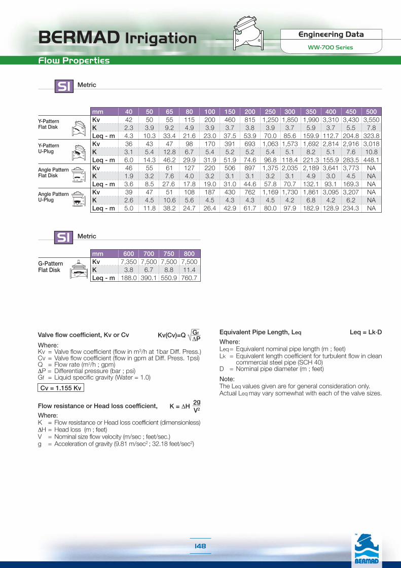
BERMAD Irrigation Engineering Data
WW-700 Series
Flow Properties
mm 600 700 750 800Kv 7,350 7,500 7,500 7,500K 3.8 6.7 8.8 11.4Leq - m 188.0 390.1 550.9 760.7
G-PatternFlat Disk
SI Metric
SI Metric
Where:Kv = Valve flow coefficient (flow in m3/h at 1bar Diff. Press.)Cv = Valve flow coefficient (flow in gpm at Diff. Press. 1psi)Q = Flow rate (m3/h ; gpm)∆P = Differential pressure (bar ; psi)Gf = Liquid specific gravity (Water = 1.0)
Valve flow coefficient, Kv or Cv Kv(Cv)=Q Gf
∆P
Cv = 1.155 Kv
Where:K = Flow resistance or Head loss coefficient (dimensionless)∆H = Head loss (m ; feet)V = Nominal size flow velocity (m/sec ; feet/sec.)g = Acceleration of gravity (9.81 m/sec2 ; 32.18 feet/sec2)
K = ∆H2gV2
Flow resistance or Head loss coefficient,
Equivalent Pipe Length, Leq
Where:Leq= Equivalent nominal pipe length (m ; feet)Lk = Equivalent length coefficient for turbulent flow in clean
commercial steel pipe (SCH 40)D = Nominal pipe diameter (m ; feet)
Note:The Leq values given are for general consideration only.Actual Leq may vary somewhat with each of the valve sizes.
Leq = Lk·D
mm 40 50 65 80 100 150 200 250 300 350 400 450 500Kv 42 50 55 115 200 460 815 1,250 1,850 1,990 3,310 3,430 3,550K 2.3 3.9 9.2 4.9 3.9 3.7 3.8 3.9 3.7 5.9 3.7 5.5 7.8Leq - m 4.3 10.3 33.4 21.6 23.0 37.5 53.9 70.0 85.6 159.9 112.7 204.8 323.8Kv 36 43 47 98 170 391 693 1,063 1,573 1,692 2,814 2,916 3,018K 3.1 5.4 12.8 6.7 5.4 5.2 5.2 5.4 5.1 8.2 5.1 7.6 10.8Leq - m 6.0 14.3 46.2 29.9 31.9 51.9 74.6 96.8 118.4 221.3 155.9 283.5 448.1Kv 46 55 61 127 220 506 897 1,375 2,035 2,189 3,641 3,773 NAK 1.9 3.2 7.6 4.0 3.2 3.1 3.1 3.2 3.1 4.9 3.0 4.5 NALeq - m 3.6 8.5 27.6 17.8 19.0 31.0 44.6 57.8 70.7 132.1 93.1 169.3 NAKv 39 47 51 108 187 430 762 1,169 1,730 1,861 3,095 3,207 NAK 2.6 4.5 10.6 5.6 4.5 4.3 4.3 4.5 4.2 6.8 4.2 6.2 NALeq - m 5.0 11.8 38.2 24.7 26.4 42.9 61.7 80.0 97.9 182.9 128.9 234.3 NA
Y-PatternFlat Disk
Y-PatternU-Plug
Angle PatternFlat Disk
Angle PatternU-Plug
148

Engineering Data
WW-700 SeriesBERMAD IrrigationDimensions & Weights
US 700 English
Flanged
Y Pattern 11/2”8.16.13.19.4208.16.13.19.422
2”8.16.13.39.6238.36.53.39.627
21/2”8.37.03.710.1298.77.33.710.133
3”9.87.93.912.049
10.48.14.112.455
4”12.68.84.514.482
13.29.85.014.995
6”16.312.65.619.416517.012.66.320.0187
8”19.715.46.823.027620.615.47.523.7322
10”23.818.98.028.547825.118.98.829.2540
12”28.521.79.533.181630.021.710.333.8904
14”28.921.710.634.184030.222.411.635.2957
16”39.029.111.843.6186540.329.112.844.61984
18”39.429.112.644.4208340.529.114.145.92132
20”43.329.114.145.9212144.729.515.347.12174
ANSI
125 ;
150
ANSI
250 ;
300
inchLWhH
Weight (lb)LWhH
Weight (lb)
H
h
L
W
W
L
H
h
Globe Pattern 24”5749
18.577
71505949
18.577
7700
28”65491978
814065491978
8140
30”7049
20.579.385807049
20.579.38580
32”7349
21.880.690207349
21.880.69020
ANSI
125 ;
150
ANSI
250 ;
300
inchLWhH
Weight (lb)LWhH
Weight (lb)
Threaded
Angle Pattern 11/2”4.96.13.13.38.9214.96.53.13.38.924
2”4.96.13.33.38.9224.96.53.33.38.925
21/2”5.97.03.74.39.9275.97.33.74.39.930
3”6.07.93.94.011.1476.38.14.14.311.351
4”7.58.74.55.013.5777.99.85.05.313.890
6”8.912.65.66.017.41579.212.66.36.517.9179
8”10.415.46.88.021.526010.915.47.58.522.0304
10”12.618.98.08.624.945213.218.98.89.325.6514
12”15.621.79.810.730.677216.321.710.311.631.3860
14”15.721.710.411.030.781616.521.711.511.831.5937
16”17.729.111.814.542.6176418.429.112.815.243.31885
18”17.729.112.614.542.6180818.429.114
15.243.31918
ANSI
125 ;
150
ANSI
250 ;
300
inchLWRhH
Weight (lb)LWRhH
Weight (lb)W
H
h
LR
Angle Pattern 2”4.84.81.63.38.912
21/2”5.54.81.94.09.515
3”6.36.42.24.511.633
BSP
; NPT
inchLWRhH
Weight (lb)
H
LR
h
W
Y Pattern 11/2”6.14.8
1.67.912
2”6.14.8
1.68.012
21/2”8.34.8
8.28.218
3”9.86.4
2.210.437
BSP
; NPT
inchLW
hH
Weight (lb)L
W
H
h
149

BERMAD Irrigation Engineering Data
WW-700 Series
Flow Charts
Y Pattern, Throttling Plug (U-Type)
1
10
15
5
Pre
ssur
e Lo
ss -
psi
10 100 1,000 10,000 100,00050 500 5,000 50,000
3” 4” 6” 8” 18”
12”
11/2”
2”
21/2”
14”
16”
20”
10”
Flow Rate - gpm (Water)
US English
Y Pattern, Flat Disk
1
10
15
5
Pre
ssur
e Lo
ss -
psi
10 100 1,000 10,000 100,00050 500 5,000 50,000
10”
24”
3” 4” 6” 8” 18”
12”
11/2”
2”
21/2”
14”
16”
20”
28”30”32”
Flow Rate - gpm (Water)
2-Way circuit "Added Head Loss" (for "V" below 6.5 f/s): 4.5 psi
2-Way circuit "Added Head Loss" (for "V" below 6.5 f/s): 4.5 psi
150

Engineering Data
WW-700 SeriesBERMAD IrrigationFlow Charts
Angle Pattern, Flat Disk
1
10
15
5
Pre
ssur
e Lo
ss -
psi
10 100 1,000 10,000 100,00050 500 5,000 50,000
12”
3” 4” 6” 8” 18”11/2”
2”
21/2”
14”
16”10”
Flow Rate - gpm (Water)
US English
Angle Pattern, Throttling Plug (U-Type)
1
10
15
5
Pre
ssur
e Lo
ss -
psi
10 100 1,000 10,000 100,00050 500 5,000 50,000
3” 4” 6” 8” 18”
12”
11/2”
2”
21/2”
14”
16”10”
Flow Rate - gpm (Water)
2-Way circuit "Added Head Loss" (for "V" below 6.5 f/s): 4.5 psi
2-Way circuit "Added Head Loss" (for "V" below 6.5 f/s): 4.5 psi
151

BERMAD Irrigation Engineering Data
WW-700 Series
Flow Properties
US English
Where:Kv = Valve flow coefficient (flow in m3/h at 1bar Diff. Press.)Cv = Valve flow coefficient (flow in gpm at Diff. Press. 1psi)Q = Flow rate (m3/h ; gpm)∆P = Differential pressure (bar ; psi)Gf = Liquid specific gravity (Water = 1.0)
Valve flow coefficient, Kv or Cv Kv(Cv)=Q Gf
∆P
Cv = 1.155 Kv
Where:K = Flow resistance or Head loss coefficient (dimensionless)∆H = Head loss (m ; feet)V = Nominal size flow velocity (m/sec ; feet/sec.)g = Acceleration of gravity (9.81 m/sec2 ; 32.18 feet/sec2)
K = ∆H2gV2
Flow resistance or Head loss coefficient,
Equivalent Pipe Length, Leq
Where:Leq= Equivalent nominal pipe length (m ; feet)Lk = Equivalent length coefficient for turbulent flow in clean
commercial steel pipe (SCH 40)D = Nominal pipe diameter (m ; feet)
Note:The Leq values given are for general consideration only.Actual Leq may vary somewhat with each of the valve sizes.
Leq = Lk·D
inch 24" 28" 30" 32"Cv 8,490 8,670 8,670 8,670K 3.8 6.7 8.8 11.4Leq-feet 616.6 1,280.0 1,807.3 2,495.6
G-PatternFlat Disk
EnglishUS
inch 1.5" 2" 2.5" 3" 4" 6" 8" 10" 12" 14" 16" 18" 20"Cv 49 58 64 133 230 530 940 1,440 2,140 2,300 3,820 3,960 4,100K 2.3 3.9 9.2 4.9 3.9 3.7 3.8 3.9 3.7 5.9 3.7 5.5 7.8Leq-feet 14.2 33.8 109.5 70.8 75.6 123.0 176.9 229.5 280.8 524.5 369.6 671.9 1,062.3Cv 41 49 54 113 200 450 800 1,230 1,820 1,950 3,250 3,370 3,490K 3.1 5.4 12.8 6.7 5.4 5.2 5.2 5.4 5.1 8.2 5.1 7.6 10.8Leq-feet 19.7 46.8 151.6 97.9 104.6 170.2 244.8 317.6 388.6 725.9 511.6 930.0 1,470.3Cv 53 64 70 146 250 580 1,040 1,590 2,350 2,530 4,210 4,360 NAK 1.9 3.2 7.6 4.0 3.2 3.1 3.1 3.2 3.1 4.9 3.0 4.5 NALeq-feet 11.7 28.0 90.5 58.5 62.5 101.6 146.2 189.7 232.0 433.4 305.5 555.3 NACv 45 54 59 124 220 500 880 1,350 2,000 2,150 3,580 3,710 NAK 2.6 4.5 10.6 5.6 4.5 4.3 4.3 4.5 4.2 6.8 4.2 6.2 NALeq-feet 16.3 38.7 125.3 80.9 86.5 140.7 202.4 262.5 321.2 599.9 422.8 768.6 NA
Y-PatternFlat Disk
Y-PatternU-Plug
Angle PatternFlat Disk
Angle PatternU-Plug
152

Engineering DataWater Meters

Features and Benefits
■ Magnetic drive■ Dry, vacuum sealed register■ Option for “reed switch” sensor■ Register can rotate 360°■ Paddle wheel design prevents jamming and
damage due to solid debris■ Measuring element suits range of water meter sizes■ Easy maintenance■ Can be installed in any orientation■ Low head loss.
Water Meterfor Irrigation and Waste Water
Turbo-IR
Turbo-IR
Isolating valve
5 x nominalmeter min.
StrainerIsolating valve
10 x nominaldiameter min.
Installations Recommendation
The TURBO-IR uses a multi-blade plastic paddlemounted at the top of the water passage, wheredisturbance from solids suspended in the water isminimal, permitting accuracy of metering in watercontaining up to 30% solid debris.
Ideal for irrigation and waste water applications.
BERMAD Irrigation Engineering Data
Water Meters Series
154

Engineering Data
Water Meters SeriesBERMAD Irrigation
Reed Switch Data
■ Cable: 2 core, 1.5m length■ Reed Switch: single■ Electrical Data:
Switching Volt.: 24 AV/DC max.Switching Current: 0.01A max.
Accuracy Curve
+5
+2
-2
-5
Qmin Qt Qn Qmax
Err
or (%
)
Flow (m3/h)
Technical Specifications
Operating Data
■ Pressure Raiting: 16 bar 232 psi■ Temperature: Water up to 40˚C,; 105˚ F
Size
Qmax - max. Flow (m3/h)Qn - Nominal Flow (m3/h)Qt - Transition Flow (m3/h)Qmin - Min. Flow (m3/h)Maximum Reading (m3)Minimum Reading (m3)
in
DN
2”
50
7035
10.52.8
12”
300
160080024064
21/2”
65
10050154
3”
80
15075
22.56
4”
100
25012537.510
5”
125
35017552.514
6”
150
500
250
75
20
8”
200
90045013535
10”
250
1200
600
180
48
Accuracy Table
9999999.99 99999999.90.01 0.1
Flow Curve
Pre
ssur
e Lo
ss (m
)
0.110
DN50
Flow (m3/h)
DN65
DN80
DN10
0DN
125
DN15
0
DN20
0DN
250
DN30
0
20 30 40 50 60 10080 200 300 400 600 1000 2000 3000
0.2
0.3
0.40.50.6
0.8
1.0
2.0
3.0
Size L - Length (mm)H - Height (mm)Weight (kg)
in
DN2”5020025210.5
12”300500
493.582.5
21/2”6520026211.8
3”80225
279.515.5
4”100250
289.517.5
5”12525030319.5
6”150300
332.530.5
8”20035038642.5
10”250450
441.560.0
Dimensions and Weights
L
H
100 liter
X
S3
1 m3
X
X
S2
10 m3
X
S1
For pulse preparation add Y/to code
DN
2”-6”50-1508”-12”
200-300Order Codes
Reed Switch Pulse
1 Pulse Per
Pulse Options
155

BERMAD Irrigation Engineering Data
Water Meters Series
Woltman Turbine MeterMagnetic Drive Dry Type
WPH
EEC CLASS B
PATTERN APPROVAL
Heavy duty and designed to handle high flow rates,the TURBOBAR WPH-Magnetic Drive water metercovers a very wide flow range, and is particularly suitedto industrial, waterworks, water distribution, watermonitoring, and agricultural applications.Based on the Woltmann principle, the helical bladesof the turbine rotate around the axis of flow.TURBOBAR products are long-life, and easy to maintainat low cost.
Features and Benefits
■ Removable and interchangeable measuring element
■ Dry type register❑ Hermetically sealed
■ Includes output option by Dry Contact (Reed Switch) and Opto-Electronic sensor, as standard❑ Digital flow converter device and a digital counter
are available on request■ Magnetic transmission keeps the register completely
separate from water; only the impeller and transmissionshaft contact water
■ Meets or exceeds ISO 4064 class B-H■ US gallons registration available on request■ EEC Approval (50-300 mm)
Rotating star for leak detectionand electronic calibration
I 9806.01.018
156
Installations Recommendation
StrainerIsolating valve Turbobar WPH Isolating valve
5 x nominaldiameter min.
3 x nominaldiameter min.

Accuracy Curve
+5
+2
-2
-5
Qmin Qt Qn Qmax
Err
or (%
)
Flow (m3/h)
Main Operating Characteristics
■ Pressure Rating: PN 16■ Temperature: 50°C
Technical Specifications
Dimensions and Weights
L
H
h
H1
20”500
500410480355700256
SizeL - Length (mm)H - Height (mm)H1 - Height (mm)h - Height (mm)W - Width (mm)Weight (kg)
11/2”40
2602003706816013
50ISO2002002707517012
21/2”65
2002002708519014
3”80
2252002709520016
4”100
25020027010423019
5”125
25020027011825020
6”150
30023030013528539
8”200
35023030016234052
10”250
450318388194395105
12”300
500318388216445120
16”400
500365435304600187
inDN 50
ANSI/BSTD3102002707016015
W
2”
Accuracy Curve
Qn - Nominal flow rate (ISO 4064) (m3/h)Qp - Max. Permanent flow (m3/h)Qmax - Max. flow rate (ISO 4064) (m3/h)Max. flow peak duty (m3/h)Qt - Transmition flow rate (±2%) (m3/h)Qmin - Min. flow rate (±5%)(ISO 4064) (m3/h)Flow rate ∆p = 0.1 bar (m3/h)Max. reading m3
Min. reading (liter)
11/2”40102020303
0.7
30
1,000,000 10,000,000 100,000,0001 10 100
20”500
1,5003,0003,0004,000300
40
5,000
12”300600
1,0001,2001,500120
18
1,500
16”400
1,0001,5002,0002,500200
30
3,000
6”15015018030030030
4.5
300
8”20025030050050050
7.5
500
10”25040060080080080
12
850
3”804060801208
1.2
60
4”1006010012020012
1.8
90
5”12510016020025020
3
120
2”50153030503
0.450.740
21/2”65253050805
0.75
55
inDN
Flow Curve
flow (m3/hr)
0.1
1
10
10 100 1000 10000
head
loss
(m)
DN500
DN400
DN300
DN250
DN200
DN150
DN125
DN100
DN80
DN65
DN50
DN40
0.2
0.30.40.60.8
2
3468
20 30 40 60 200 300 600 2000 4000
Engineering Data
Water Meters SeriesBERMAD Irrigation
157
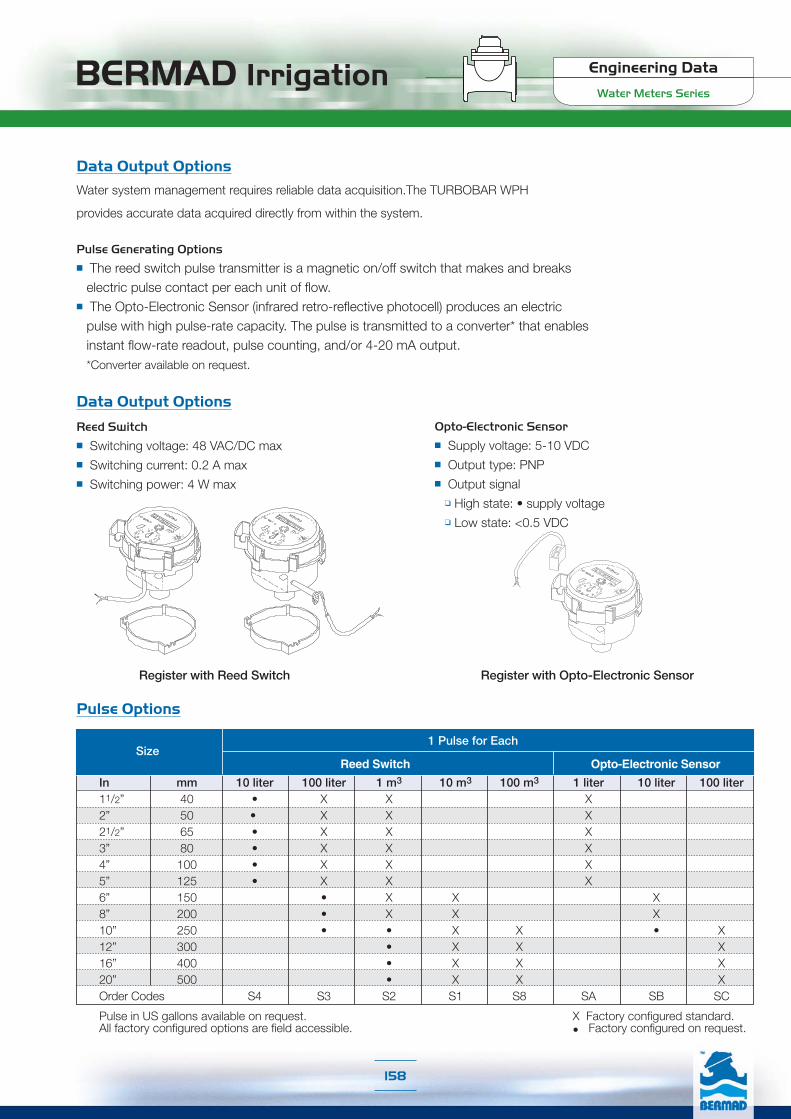
Data Output Options
Water system management requires reliable data acquisition.The TURBOBAR WPH
provides accurate data acquired directly from within the system.
Pulse Generating Options
■ The reed switch pulse transmitter is a magnetic on/off switch that makes and breakselectric pulse contact per each unit of flow.
■ The Opto-Electronic Sensor (infrared retro-reflective photocell) produces an electricpulse with high pulse-rate capacity. The pulse is transmitted to a converter* that enablesinstant flow-rate readout, pulse counting, and/or 4-20 mA output.*Converter available on request.
Data Output Options
Reed Switch
■ Switching voltage: 48 VAC/DC max■ Switching current: 0.2 A max■ Switching power: 4 W max
Opto-Electronic Sensor
■ Supply voltage: 5-10 VDC■ Output type: PNP■ Output signal
❑ High state: • supply voltage❑ Low state: <0.5 VDC
Register with Reed Switch Register with Opto-Electronic Sensor
Pulse Options
Reed Switch Opto-Electronic Sensor
1 Pulse for EachSize
In mm 10 liter 100 liter 1 m3 10 m3 100 m3 1 liter 10 liter 100 liter11/2” 40 • X X X2” 50 • X X X21/2” 65 • X X X3” 80 • X X X4” 100 • X X X5” 125 • X X X6” 150 • X X X8” 200 • X X X10” 250 • • X X • X12” 300 • X X X16” 400 • X X X20” 500 • X X XOrder Codes S4 S3 S2 S1 S8 SA SB SC
Pulse in US gallons available on request. X Factory configured standard.All factory configured options are field accessible. • Factory configured on request.
BERMAD Irrigation Engineering Data
Water Meters Series
158
159
Engineering DataIR-350 Series
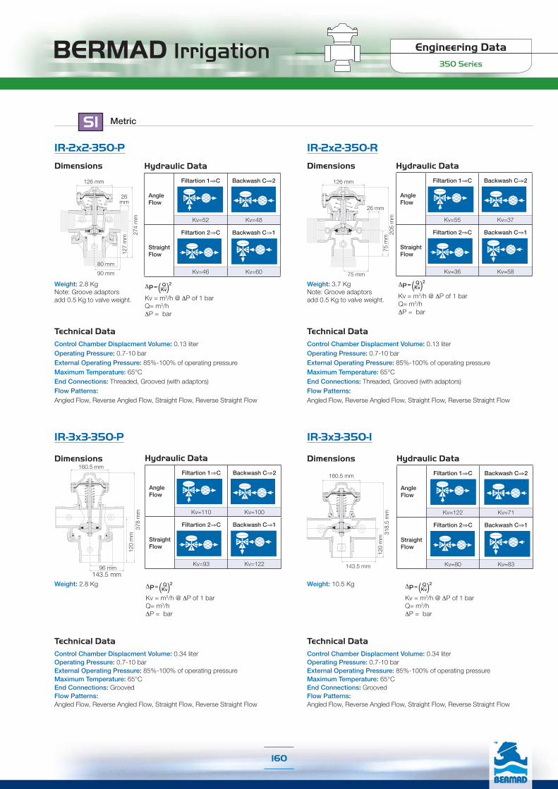
BERMAD Irrigation350 Series
Engineering Data
160
Technical DataControl Chamber Displacment Volume: 0.13 literOperating Pressure: 0.7-10 barExternal Operating Pressure: 85%-100% of operating pressureMaximum Temperature: 65°CEnd Connections: Threaded, Grooved (with adaptors)Flow Patterns: Angled Flow, Reverse Angled Flow, Straight Flow, Reverse Straight Flow
IR-2x2-350-P
Technical DataControl Chamber Displacment Volume: 0.13 literOperating Pressure: 0.7-10 barExternal Operating Pressure: 85%-100% of operating pressureMaximum Temperature: 65°CEnd Connections: Threaded, Grooved (with adaptors)Flow Patterns: Angled Flow, Reverse Angled Flow, Straight Flow, Reverse Straight Flow
Weight: 3.7 KgNote: Groove adaptors add 0.5 Kg to valve weight.
Hydraulic Data
Angle Flow
Filtartion 1⇒C Backwash C⇒2
Kv=55 Kv=37
StraightFlow
Filtartion 2⇒C Backwash C⇒1
Kv=36 Kv=58
Kv = m3/h @ ΔP of 1 barQ= m3/h ΔP = bar
(Kv)Q 2
ΔP=
205
mm
26 mm
126 mm
75 m
m
75 mm90 mm
274
mm
26 mm
127
mm
126 mm
80 mm
Weight: 2.8 KgNote: Groove adaptors add 0.5 Kg to valve weight. Kv = m3/h @ ΔP of 1 bar
Q= m3/h ΔP = bar
(Kv)Q 2
ΔP=
Hydraulic Data
Angle Flow
Filtartion 1⇒C Backwash C⇒2
Kv=52 Kv=48
StraightFlow
Filtartion 2⇒C Backwash C⇒1
Kv=46 Kv=60
Dimensions
SI Metric
Dimensions
IR-2x2-350-R
Technical DataControl Chamber Displacment Volume: 0.34 literOperating Pressure: 0.7-10 barExternal Operating Pressure: 85%-100% of operating pressureMaximum Temperature: 65°CEnd Connections: Grooved Flow Patterns: Angled Flow, Reverse Angled Flow, Straight Flow, Reverse Straight Flow
Weight: 10.5 Kg
Hydraulic Data
Angle Flow
Filtartion 1⇒C Backwash C⇒2
Kv=122 Kv=71
StraightFlow
Filtartion 2⇒C Backwash C⇒1
Kv=80 Kv=83
160.5 mm
143.5 mm
120
mm
318.
5 m
m
Dimensions
Technical DataControl Chamber Displacment Volume: 0.34 literOperating Pressure: 0.7-10 barExternal Operating Pressure: 85%-100% of operating pressureMaximum Temperature: 65°CEnd Connections: Grooved Flow Patterns: Angled Flow, Reverse Angled Flow, Straight Flow, Reverse Straight Flow
Hydraulic Data
Angle Flow
Filtartion 1⇒C Backwash C⇒2
Kv=110 Kv=100
StraightFlow
Filtartion 2⇒C Backwash C⇒1
Kv=93 Kv=122
378
mm
120
mm
143.5 mm
160.5 mm
96 mm
Weight: 2.8 Kg
Dimensions
IR-3x3-350-P IR-3x3-350-I
Kv = m3/h @ ΔP of 1 barQ= m3/h ΔP = bar
(Kv)Q 2
ΔP=
Kv = m3/h @ ΔP of 1 barQ= m3/h ΔP = bar
(Kv)Q 2
ΔP=

BERMAD Irrigation350 Series
Engineering Data
161
Operation
A Hydraulic Command [1], which pressurizes the Upper Control Chamber [2], forces the Diaphragm [3] actuated Plug Assembly [4] to move towards the Supply Port Seat [5], eventually sealing it drip tight. This allows flow from the filter through the Drain Port Seat [6]. Venting the upper control chamber causes the line pressure, together with the Spring [7] force, to move the Valve back to filtration mode.
Angle Flow
2
Filtration Backwash
[7]
[2]
[5]
[6][3]
[4]
[1]
2
1
C
1
C
Operation
A Hydraulic Command [1], which pressurizes the Control Chamber [2], forces the Diaphragm [3] actuated Plug Assembly [4] to move towards the Supply Port Seat [5], eventually sealing it drip tight. This allows flow from the filter through the Drain Port Seat [6]. During Valve closing, the Plug [7] blocks the drain port seat, preventing mixing of supply water with waste water. Venting the control chamber causes the line pressure to move the Valve back to filtration mode.
Filtration Backwash
[1][2]
[3]
[4] [6][5]
2 C
1
2 C
1
Technical DataControl Chamber Displacement Volume: 1.055 liter Operating Pressure: 0.7-16 barExternal Operating Pressure: 100% of operating pressureMaximum Temperature: 65°CEnd Connections: Inlet & Outlet: Flanged, Grooved Drain: Threaded Flow Pattern: Angled Flow
Hydraulic Data
Angle Flow
Filtartion 1⇒C Backwash C⇒2
Kv=212 Kv=106
F= FlangedG= GroovedWeight: Flanged 39.0 KgGrooved 21.0 Kg
125 mmF 135 mmG 152 mm
F 13
8 m
mG
123
mm
F 29
5 m
mG
277
mm
245 mm
IR-4x3-350-A-I IR-4x4-350-A-I
Dimensions
Technical DataControl Chamber Displacement Volume: 1.055 literOperating Pressure: 0.7-16 barExternal Operating Pressure: 100% of operating pressureMaximum Temperature: 65°CEnd Connections: Inlet & Outlet: Flanged, Grooved Drain: Threaded Flow Pattern: Angled Flow
Hydraulic Data
Angle Flow
Filtartion 1⇒C Backwash C⇒2
Kv=212 Kv=141
Weight: Grooved 22.0 Kg
245 mm
152 mm 152 mm
123
mm
277
mm
SI Metric
Dimensions
Operation Double Chamber Operation Single Chamber
Kv = m3/h @ ΔP of 1 barQ= m3/h ΔP = bar
(Kv)Q 2
ΔP=
Kv = m3/h @ ΔP of 1 barQ= m3/h ΔP = bar
(Kv)Q 2
ΔP=

BERMAD Irrigation350 Series
Engineering Data
162
Technical DataControl Chamber Displacment Volume: 0.04 gallonOperating Pressure: 10-145 psiExternal Operating Pressure: 85%-100% of operating pressureMaximum Temperature: 150°FEnd Connections: Threaded, Grooved (with adaptors)Flow Patterns: Angled Flow, Reverse Angled Flow, Straight Flow, Reverse Straight Flow
IR-2x2-350-P
Technical DataControl Chamber Displacment Volume: 0.04 gallonOperating Pressure: 10-145 psiExternal Operating Pressure: 85%-100% of operating pressureMaximum Temperature: 150°FEnd Connections: Threaded, Grooved (with adaptors)Flow Patterns: Angled Flow, Reverse Angled Flow, Straight Flow, Reverse Straight Flow
Weight: 8.2 lbs.Note: Groove adaptors add 1.1 lbs. to valve weight.
Hydraulic Data
Angle Flow
Filtartion 1⇒C Backwash C⇒2
Cv=64 Cv=43
StraightFlow
Filtartion 2⇒C Backwash C⇒1
Cv=42 Cv=67
205
mm
26 mm
126 mm
75 m
m
75 mm31/2
93 /4"
1"
5"
5"
31/8"
Weight: 6.2 lbs.Note: Groove adaptors add 1.1 lbs. to valve weight.
Hydraulic Data
Angle Flow
Filtartion 1⇒C Backwash C⇒2
Cv=60 Cv=56
StraightFlow
Filtartion 2⇒C Backwash C⇒1
Cv=53 Cv=70
Dimensions
US English
Dimensions
IR-2x2-350-R
Technical DataControl Chamber Displacment Volume: 0.09 gallonOperating Pressure: 10-145 psiExternal Operating Pressure: 85%-100% of operating pressureMaximum Temperature: 150°FEnd Connections: Grooved Flow Patterns: Angled Flow, Reverse Angled Flow, Straight Flow, Reverse Straight Flow
Hydraulic Data
Angle Flow
Filtartion 1⇒C Backwash C⇒2
Kv=141 Kv=82
StraightFlow
Filtartion 2⇒C Backwash C⇒1
Kv=92 Kv=96
Weight: 23.1 lbs.
Cv = gpm @ ΔP of 1 psiQ= gpm ΔP = psi
(Cv)Q 2
ΔP=
65/16"
51/16"
411/1
6"12
9 /16
"
Dimensions
IR-3x3-350-P IR-3x3-350-I
Cv = gpm @ ΔP of 1 psiQ= gpm ΔP = psi
(Cv)Q 2
ΔP=
Cv = gpm @ ΔP of 1 psiQ= gpm ΔP = psi
(Cv)Q 2
ΔP=
Technical DataControl Chamber Displacment Volume: 0.09 gallonOperating Pressure: 10-145 psiExternal Operating Pressure: 85%-100% of operating pressureMaximum Temperature: 150°FEnd Connections: Grooved Flow Patterns: Angled Flow, Reverse Angled Flow, Straight Flow, Reverse Straight Flow
Hydraulic Data
Angle Flow
Filtartion 1⇒C Backwash C⇒2
Cv=127 Cv=115
StraightFlow
Filtartion 2⇒C Backwash C⇒1
Cv=107 Cv=141
147 /
8"411
/16"
511/16”
65/16"
33/4"
Weight: 6.2 lbs.
Dimensions
Cv = gpm @ ΔP of 1 psiQ= gpm ΔP = psi
(Cv)Q 2
ΔP=
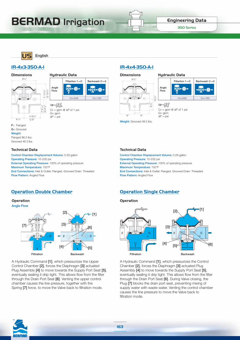
BERMAD Irrigation350 Series
Engineering Data
163
Operation
A Hydraulic Command [1], which pressurizes the Upper Control Chamber [2], forces the Diaphragm [3] actuated Plug Assembly [4] to move towards the Supply Port Seat [5], eventually sealing it drip tight. This allows flow from the filter through the Drain Port Seat [6]. Venting the upper control chamber causes the line pressure, together with the Spring [7] force, to move the Valve back to filtration mode.
Angle Flow
2
Filtration Backwash
[7]
[2]
[5]
[6][3]
[4]
[1]
2
1
C
1
C
Operation
A Hydraulic Command [1], which pressurizes the Control Chamber [2], forces the Diaphragm [3] actuated Plug Assembly [4] to move towards the Supply Port Seat [5], eventually sealing it drip tight. This allows flow from the filter through the Drain Port Seat [6]. During Valve closing, the Plug [7] blocks the drain port seat, preventing mixing of supply water with waste water. Venting the control chamber causes the line pressure to move the Valve back to filtration mode.
Filtration Backwash
[1][2]
[3]
[4] [6][5]
2 C
1
2 C
1
Technical DataControl Chamber Displacement Volume: 0.29 gallonOperating Pressure: 10-232 psiExternal Operating Pressure: 100% of operating pressureMaximum Temperature: 150°FEnd Connections: Inlet & Outlet: Flanged, Grooved Drain: Threaded Flow Pattern: Angled Flow
Hydraulic Data
Angle Flow
Filtartion 1⇒C Backwash C⇒2
Cv=245 Cv=122
F= FlangedG= GroovedWeight: Flanged 86.0 lbs.Grooved 46.3 lbs
47/8"F 65/8"G 6"
F 57 /
16"
G 4
7 /8"
F 11
5 /8"
G 1
07 /8"
95/8"
Cv = gpm @ ΔP of 1 psiQ= gpm ΔP = psi
(Cv)ΔQ 2
ΔP=
IR-4x3-350-A-I IR-4x4-350-A-I
Dimensions
Technical DataControl Chamber Displacement Volume: 0.29 gallonOperating Pressure: 10-232 psiExternal Operating Pressure: 100% of operating pressureMaximum Temperature: 150°FEnd Connections: Inlet & Outlet: Flanged, Grooved Drain: Threaded Flow Pattern: Angled Flow
Hydraulic Data
Angle Flow
Filtartion 1⇒C Backwash C⇒2
Cv=245 Cv=163
Weight: Grooved 48.5 lbs.
95/8"
6" 6"
47 /8"
107 /
8"
Cv = gpm @ ΔP of 1 psiQ= gpm ΔP = psi
(Cv)Q 2
ΔP=
US English
Dimensions
Operation Double Chamber Operation Single Chamber
Engineering DataIR-200 Series

Engineering Data
200 SeriesBERMAD IrrigationProduct Parts Features, Hydraulic Valve
[ 1 ] Fastening Bolts & Nuts
6 Stainless Steel bolts and nuts (11/2-2"; DN40-50 valves) fastenvalve cover to body, ensuring quick in-line inspection and service.
[2] Valve Cover (Hydraulic Type)Simple and light construction enables quick in-line inspectionand service.[2.1] Flow Stem (Optional)
[3] Auxiliary Closing Spring
One single spring fully meets valve requirements foroperating pressure range, ensuring low opening pressureand secured closing.
[4] Seal Disk Assembly (Hydraulic Type)
The seal disk assembly includes a flexible, carefully balanced, andperipherally supported diaphragm and a rugged guided plugwith elastomeric sealing surface. This internal design enables:
High flow rate with low head loss
Smooth valve opening and closing
Accurate and stable regulation
Low opening and actuation pressure
No diaphragm erosion and distortion
Same diaphragm and spring fully meet the valve's operatingpressure range requirements
[5] Diaphragm Supporting Ring
[6] Valve Body (Hydraulic Type)
Glass-Filled Nylon to meet rough service conditions obtaininghigh chemical and cavitation resistance. Full bore seat withunobstructed flow path, free of any in-line ribs, supporting cage,or shafts. [6]
[1]
[5]
[3]
[2]
[2.1]
[1]
[4]
165

BERMAD Irrigation Engineering Data
200 Series
Product Parts Features, Electric Valve
[ 1 ] Fastening Bolts & Nuts
6 Stainless Steel bolts and nuts (11/2-2"; DN40-50 valves) fastenvalve cover to body, ensuring quick in-line inspection and service.
[2] Valve Cover (Electric Type)Simple and light construction enables quick in-line inspectionand service.[2.1] 2-Way Solenoid Actuator
[2.2] Manuale Override Handle
[2.3] Needle - Restricts inlet flow & eliminates internal
restriction clogging.
[2.4] Flow Stem (optional)
[3] Auxiliary Closing Spring
One single spring fully meets valve requirements foroperating pressure range, ensuring low opening pressureand secured closing.
[4] Seal Disk Assembly (Electric Type)
The seal disk assembly includes a flexible, carefully balanced, andperipherally supported diaphragm and a rugged guided plugwith elastomeric sealing surface. This internal design enables:
High flow rate with low head loss
Smooth valve opening and closing
Accurate and stable regulation
Low opening and actuation pressure
No diaphragm erosion and distortion
Same diaphragm and spring fully meet the valve's operatingpressure range requirements
[4.1] Internal Restriction
[5] Diaphragm Supporting Ring
[6] Valve Body (Electric Type)
Glass-Filled Nylon to meet rough service conditions obtaininghigh chemical and cavitation resistance. Full bore seat withunobstructed flow path, free of any in-line ribs, supporting cage,or shafts.
[6.1] Internal Control Circuit Outlet
[2.4]
[2.1]
[1]
[2.3]
[3]
[4]
[5]
[6.1]
[6][6]
[4.1]
[2.2]
166

Engineering Data
200 SeriesBERMAD Irrigation
SI Metric
Technical Data
Dimensions & Weights
Flow Chart
* Without flow control handle**Control Chamber Displacement Volume (liter)
DN20 DN25 DN40 DN50 DN40 DN50110 110 160 170 80 85115 115 180 190 190 21022 22 35 38 40 6078 78 125 125 125 125
0.35 0.33 1.0 1.1 0.95 0.910.015 0.015 0.072 0.072 0.072 0.072
PatternSize
L (mm)H (mm)R (mm)W (mm)Weight*(kg)CCDV** (lit)
Globe Angle
R
H
LW
R
H
LW
Flow Rate (m3/h)1 1.5 2 3 4 5 6 8 10 15 20 30 40 50 60 80
Pre
ssur
e D
rop
(bar
)
DN20-G
.04
.05
.06
.08
0.1
0.15
0.2
0.3
0.4
0.50.6
0.8
1.0DN25-G
DN40-GDN40-A
DN50-GDN50-A
2-Way circuit "Added Head Loss" (for "V" below 2 m/s): 0.3 bar
Technical SpecificationsAvailable Patterns & Sizes:Globe: DN: 20, 25, 40 & 50Angle: DN: 40 & 50Available End Connections:BSP-T; NPT female threadsPressure Rating:10 barOperating Pressure Range: 0.7-10 bar
Temperature: Water up to 60°CStandard Materials:
Body & Cover: Nylon ReinforcedMetal Parts: Stainless SteelDiaphragm: Natural RubberSeals: NBR [Buna-N]Spring: Stainless SteelCover bolts: Stainless Steel
167

BERMAD Irrigation Engineering Data
200 Series
Flow ChartsTechnical Data
Dimensions & Weights
* Without flow control handle**Control Chamber Displacement Volume (gallons)
US English
Flow Chart
PatternSize
L (inch)H (inch)R (inch)W (inch)Weight* (lb)CCDV** (gal)
Globe Angle1/2”
45/16
41/27/8
31/16
0.770.004
1”45/16
41/27/8
31/16
0.730.004
11/2”65/16
71/813/8
415/16
2.20.02
2”611/16
71/211/2
415/16
2.40.02
11/2”33/16
71/219/16
45/16
2.10.02
2”33/881/423/8
415/16
2.00.02
R
H
LWR
H
LW
2-Way circuit "Added Head Loss" (for "V" below 6.5 f/s): 4.5 psi
Technical SpecificationsAvailable Patterns & Sizes:Globe: 3/4”, 1”, 11/2”, 2”Angle: 11/2”, 2”Available End Connections:BSP-T; NPT female threadsPressure Rating: 150 psiOperating Pressure Range: 10-150 psi
Temperature: Water up to 140°FStandard Materials:
Body & Cover: Nylon ReinforcedMetal Parts: Stainless SteelDiaphragm: Natural RubberSeals: NBR [Buna-N]Spring: Stainless SteelCover bolts: Stainless Steel
Flow Rate - Water (gpm)
Pres
sure
Dro
p (p
si)
3 4 6 8 10 20 30 40 60 80 100 200 300
0.1
0.2
0.30.4
0.60.81.0
2.0
3.04.0
6.08.0
10.0
20.0
11/2”-G11/2”-A
2”-G2”-A
1/2”-G 1”-G
168

Engineering DataIR-300 Series

BERMAD Irrigation Engineering Data
300 Series
Product Parts Features
[3.1]
[3.2]
[3.3]
[2]
[1] Double Chambered Actuator Actuator assembly can be removed as one integral unit
Simple on-site conversion to single chambered
[2] Cover Assembly[2.1] Optional cover type is capable of accepting
a Flow Stem
[3] Diaphragm Assembly
The flexible nylon reinforced diaphragm is supportedover the majority of its surface. Diaphragm load islimited to only the stretching forces applied to theactive area.
[4] Inherent Separation PartitionThe inherent separation provides complete central guiding for the valve movingassembly. The separation partition separates the lower control chamber fromthe flow in both the single chambered, and the double chambered configurations.
[5] SpringsDue to its superior hydraulic closing force, the double chambered actuatordoes not require an auxiliary closing spring, which is required for singlechambered configurations.
An auxiliary opening spring can be applied for near zero-pressure applicationswith external control pressure.
[5.1] Lifting Spring (for zero or near zero pressure applications)
[5.2] Auxiliary Closing Spring (for single chambred valves only)
[6] Vulcanized Seal DiskSelf-aligning seal disk provides balanced, free movement and a resilient sealfor perfect, drip tight sealing. The Seal disk is harnessed to the valve shaft bya stainless steel split pin.
Raised,full bore, clear of obstructions; no ribs or stem guides
[8] Valve Body (“Y” or Angle pattern)Hydro-dynamically designed for efficient flow with minimal pressure loss.Semi-Straight flow increases capacity by 25% over standard globe valves.
[1]
[3.4]
[5.1]
[5.2]
[4]
[3]
[6]
[8]
[1]
[7]
[2.1]
170
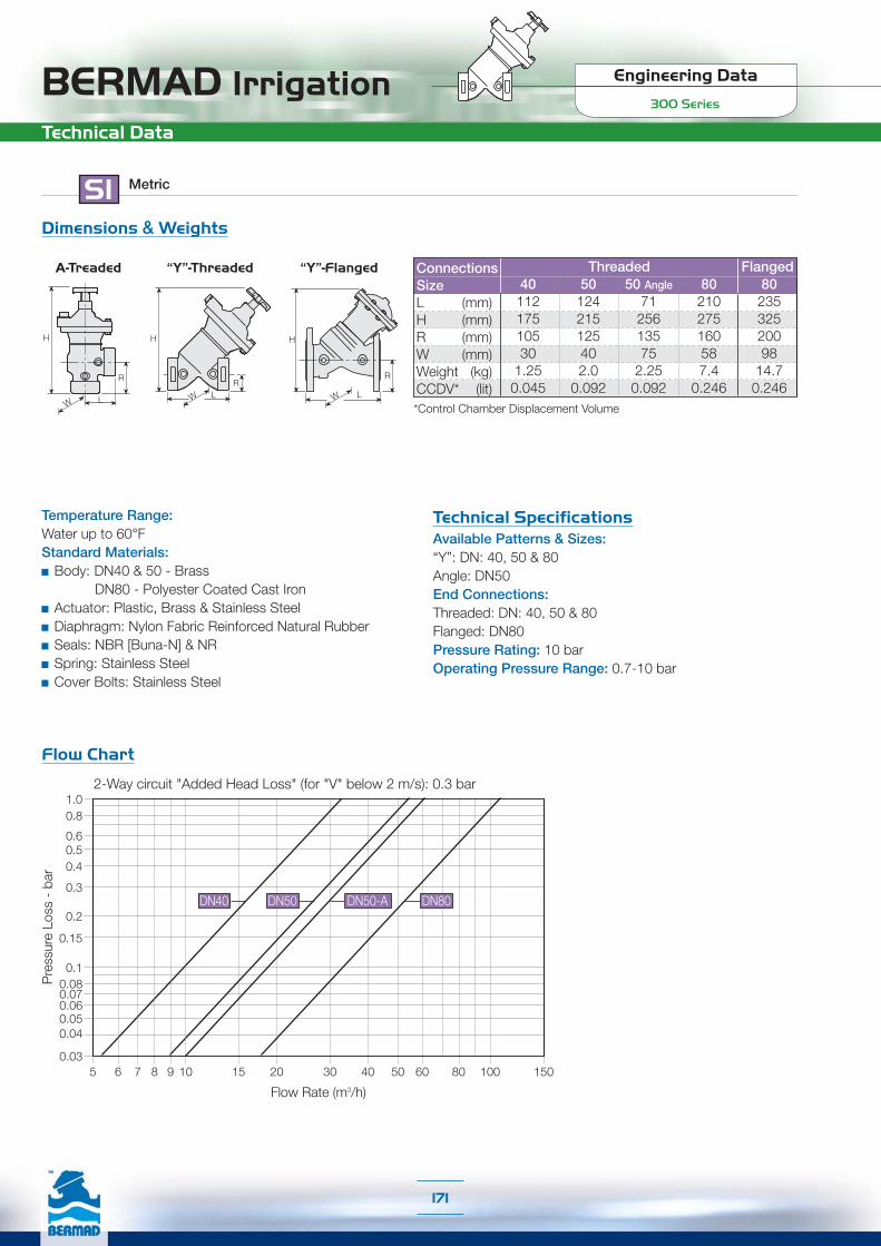
Engineering Data
300 SeriesBERMAD Irrigation
SI Metric
Technical Data
Technical SpecificationsAvailable Patterns & Sizes:“Y”: DN: 40, 50 & 80Angle: DN50End Connections:Threaded: DN: 40, 50 & 80Flanged: DN80Pressure Rating: 10 barOperating Pressure Range: 0.7-10 bar
Temperature Range:Water up to 60°FStandard Materials:
Body: DN40 & 50 - Brass DN80 - Polyester Coated Cast Iron
Actuator: Plastic, Brass & Stainless SteelDiaphragm: Nylon Fabric Reinforced Natural RubberSeals: NBR [Buna-N] & NRSpring: Stainless SteelCover Bolts: Stainless Steel
Dimensions & Weights
L
H
W
R
W L
H
W
R
H
L
R
ConnectionsSizeL (mm)H (mm)R (mm)W (mm)Weight (kg)CCDV* (lit)
Threaded Flanged
*Control Chamber Displacement Volume
40 50 50 Angle 80 80112 124 71 210 235175 215 256 275 325105 125 135 160 20030 40 75 58 98
1.25 2.0 2.25 7.4 14.70.045 0.092 0.092 0.246 0.246
Flow Chart
2-Way circuit "Added Head Loss" (for "V" below 2 m/s): 0.3 bar1.00.8
0.60.50.4
0.3
0.2
0.15
0.03
Pre
ssur
e Lo
ss -
bar
Flow Rate (m3/h)
5 6 7 8 9 10 15 20 30 40 50 60 80 100 150
0.10.080.070.060.050.04
DN40 DN50 DN80DN50-A
171
“Y”-ThreadedA-Treaded “Y”-Flanged
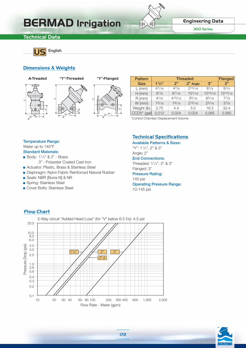
BERMAD Irrigation Engineering Data
300 Series
Technical Data
US English
Technical SpecificationsAvailable Patterns & Sizes:“Y”: 11/2”, 2” & 3”Angle: 2”End Connections:Threaded: 11/2”, 2” & 3”Flanged: 3”Pressure Rating:145 psiOperating Pressure Range:10-145 psi
Temperature Range:Water up to 140°FStandard Materials:
Body: 11/2” & 2” - Brass 3” - Polyester Coated Cast Iron
Actuator: Plastic, Brass & Stainless SteelDiaphragm: Nylon Fabric Reinforced Natural RubberSeals: NBR [Buna-N] & NRSpring: Stainless SteelCover Bolts: Stainless Steel
Dimensions & Weights
L
H
W
R
W L
H
W
R
H
L
R
PatternSize
L (mm)H (mm)R (mm)W (mm)
Weight (lb)CCDV* (gal)
Threaded Flanged
*Control Chamber Displacement Volume
Flow Chart
11/2”47/16
67/841/813/16
2.750.012
2”47/887/16
415/16
19/16
4.40.024
2” Angle213/16
101/16
55/16
215/16
5.00.024
3”81/4
1013/16
65/16
25/16
16.30.065
3”91/4
1213/16
77/837/832.40.065
2-Way circuit "Added Head Loss" (for "V" below 6.5 f/s): 4.5 psi
11/2” 2”
2”-A
3”
Pre
ssur
e D
rop
(psi
)
Flow Rate - Water (gpm)
20.0
0.1
0.2
0.30.4
0.60.81.0
2.0
3.04.0
6.08.0
10.0
10 20 30 40 60 80 100 200 300 400 600 1,000 2,000
172
“Y”-ThreadedA-Treaded “Y”-Flanged

Engineering DataIR-R00 Series
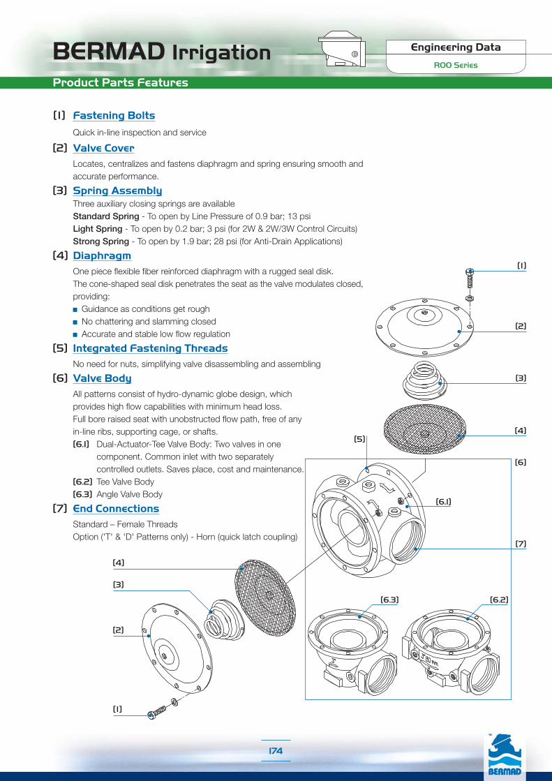
BERMAD Irrigation Engineering Data
R00 Series
Product Parts Features
[3]
[1]
[2]
[6.1]
[4]
[7]
[5]
[4]
[3]
[2]
[1]
[6]
[6.3] [6.2]
[1] Fastening Bolts
Quick in-line inspection and service
[2] Valve CoverLocates, centralizes and fastens diaphragm and spring ensuring smooth andaccurate performance.
[3] Spring AssemblyThree auxiliary closing springs are availableStandard Spring - To open by Line Pressure of 0.9 bar; 13 psiLight Spring - To open by 0.2 bar; 3 psi (for 2W & 2W/3W Control Circuits)Strong Spring - To open by 1.9 bar; 28 psi (for Anti-Drain Applications)
[4] DiaphragmOne piece flexible fiber reinforced diaphragm with a rugged seal disk.The cone-shaped seal disk penetrates the seat as the valve modulates closed,providing:
Guidance as conditions get roughNo chattering and slamming closedAccurate and stable low flow regulation
[5] Integrated Fastening ThreadsNo need for nuts, simplifying valve disassembling and assembling
[6] Valve BodyAll patterns consist of hydro-dynamic globe design, whichprovides high flow capabilities with minimum head loss.Full bore raised seat with unobstructed flow path, free of anyin-line ribs, supporting cage, or shafts.[6.1] Dual-Actuator-Tee Valve Body: Two valves in one
component. Common inlet with two separatelycontrolled outlets. Saves place, cost and maintenance.
[6.2] Tee Valve Body[6.3] Angle Valve Body
[7] End ConnectionsStandard – Female ThreadsOption ('T' & 'D' Patterns only) - Horn (quick latch coupling)
174
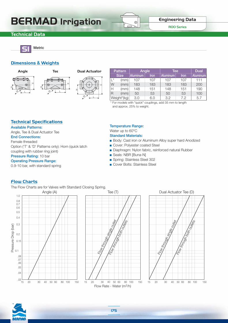
Engineering Data
R00 SeriesBERMAD Irrigation
Tee (T)
15 20 30 40 50 60 80 100 150
Flow Rate - Water (m3/h)
Flow
thro
ugh
sing
le o
utle
tFl
ow th
roug
h bo
th o
utle
ts
SI Metric
Technical Data
Technical SpecificationsAvailable Patterns:Angle, Tee & Dual Actuator TeeEnd Connections:Female threadedOption ('T' & 'D' Patterns only): Horn (quick latchcoupling with rubber ring joint)Pressure Rating: 10 barOperating Pressure Range:0.9-10 bar, with standard spring
Temperature Range:Water up to 60°CStandard Materials:
Body: Cast iron or Aluminum Alloy super hard AnodizedCover: Polyester coated SteelDiaphragm: Nylon fabric, reinforced natural RubberSeals: NBR [Buna-N]Spring: Stainless Steel 302Cover Bolts: Stainless Steel
Dimensions & Weights
Flow ChartsThe Flow Charts are for Valves with Standard Closing Spring.
15
Dual Actuator Tee (D)
20 30 40 50 60 80 100 150
Flow
thro
ugh
both
out
lets
Flow
thro
ugh
sing
le o
utle
t
Dual
* For models with "quick" couplings, add 35 mm to lengthand approx. 25% to weight.
Aluminum Iron Aluminum Iron Aluminum107 107 107 107 111183 183 183 183 200148 151 148 151 19050 53 50 53 1003.0 6.0 3.2 7.2 5.7
PatternSize
L* (mm)W (mm)H (mm)R (mm)Weight*(kg)
Angle Tee Dual
Angle (A)
.03
.04
.05
0.2
0.3
0.4
0.5
0.60.7
.07
0.15
.06
.08
0.1
15 20 30 40 50 60 80 100
0.8
1.0
150
Pre
ssur
e D
rop
(bar
)
H
R
LW
H
R
LW
H
R
LW
TeeAngle Dual Actuator
175

BERMAD Irrigation Engineering Data
R00 Series
Flow ChartsTechnical Data
US English
Technical Specificationsvailable Patterns:Angle, Tee & Dual Actuator TeeEnd Connections:Female threadedOption ('T' & 'D' Patterns only): Horn (quick latchcoupling with rubber ring joint)Pressure Rating: 145 psiOperating Pressure Range:13-145 psi, with standard spring
Temperature Range:Water up to 140°FStandard Materials:
Body: Cast iron or Aluminum Alloy super hard AnodizedCover: Polyester coated SteelDiaphragm: Nylon fabric, reinforced natural RubberSeals: NBR [Buna-N]Spring: Stainless SteelCover Bolts: Stainless Steel
Dimensions & Weights
PatternSize
L* (inch)W (inch)H (inch)R (inch)Weight* (lb)
Angle Dual
* For models with "quick" couplings, add 13/8" to lengthand approx. 25% to weight.
Aluminum47/32
713/64
513/16
26.6
Iron47/32
713/64
515/16
21/16
13.2
Aluminum47/32
713/64
513/16
27.1
Iron47/32
713/64
515/16
21/16
15.9
Aluminum43/877/871/2
315/16
12.6
Flow ChartsThe Flow Charts are for Valves with Standard Closing Spring.
Tee
Dual Actuator Tee (D)Angle (A)
30 40 60 80 100 200 300400 600
Pre
ssur
e D
rop
(psi
)
20.
0.1
0.2
0.3
0.4
0.6
0.81.0
2.0
3.0
4.0
6.0
8.010.0
Tee T
Flow Rate - Water (gpm)30 40 60 80 100 200 300400 600 30 40 60 80 100 200 300400 600
Flow
thro
ugh
both
out
lets
Flow
thro
ugh
sing
le o
utle
t
Flow
thro
ugh
singl
e ou
tlet
Flow
thro
ugh
both
out
lets
H
R
LW
H
R
LW
H
R
LW
TeeAngle Dual Actuator
176

177
Engineering DataPRV Series

BERMAD IrrigationPRV Series
Main Network
178
1"-PRV & 1"-PRV-05
¾"-PRV & ¾"-PRV-05
SI Metric
Flow ChartRequired supply pressure above setting
Flowm3/h
∆Pbar
1.0
0.8
0.6
0.4
0.2
0.0
0.0 1.0 2.0 3.0 4.0 5.0 6.0
To calculate the minimum required supply pressure, add the ΔP in the Flow Chart to PRV desired set point.
Flow ChartRequired supply pressure above setting
Flowm3/h
∆Pbar
1.0
0.8
0.6
0.4
0.2
0.00.0 0.5 1.0 1.5 2.0 2.5 3.0
To calculate the minimum required supply pressure, add the ΔP in the Flow Chart to PRV desired set point.
Technical DataSize: 1”; DN25 End Connections: Female Threads BSP; NPTFlow Range Model 1”-PRV: 0.45-7 m3/hFlow Range Model 1”-PRV-05: 0.1-7 m3/hPressure Ratings: 9 barOperating Pressure Range: 0.7-9 bar
Setting Springs Selection TableSetting Range
bar Spring Color Spring Name
0.5-1.2 White B
1.0-2.0 Red C
1.5-3.5 Black D
3.0-5.5 Brown Q
Dimensions
65 mm 114 mm
45 m
m
160
mm
Weight: 0.36 Kg
Technical DataSize: ¾”; DN20 End Connections: Threaded Inlet: Female BSP; NPTOutlet: Female BSP; NPT or Male BSPT; NPTFlow Range Model 3/4”-PRV: 0.2-5 m3/hFlow Range Model 3/4”-PRV-05: 0.01-3 m3/hPressure Ratings: 9 barOperating Pressure Range: 0.7-9 bar
Setting Springs Selection TableSetting Range
bar Spring Color Spring Name
0.5-1.2 Yellow A
0.8-2.5 White B
2.0-4.0 Red C
3.5-6.0 Black D
Dimensions
88 mmWeight: 0.13 Kg
45 mm
17 m
m10
0 m
m

BERMAD IrrigationPRV Series
Main Network
179
SI Metric
Technical DataSize: 1½”; DN40 End Connections: Female Threads BSP; NPTFlow Range: 0.45-18 m3/hPressure Ratings: 9 barOperating Pressure Range: 0.7-9 bar
Setting Springs Selection TableSetting Range
bar Spring Color Spring Name
0.5-1.2 White B
1.0-2.0 Red C
1.5-3.5 Black D
3.0-5.5 Brown Q
Flow Chart
Required supply pressure above setting
Flowm3/h0.0 2.0 4.0 6.0 8.0 10.0 12.0
∆Pbar
1.0
0.8
0.6
0.4
0.2
0.0
To calculate the minimum required supply pressure, add the ΔP in the Flow Chart to PRV desired set point.
Technical DataSize: 2”; DN50 End Connections: Female Threads BSP; NPTFlow Range: 4-25 m3/hPressure Ratings: 8 barOperating Pressure Range: 2-8 bar
Flow Chart
Required supply pressure above setting
Flowm3/h0.0 7.5 15.0 22.5 30.0 37.5 45.0
∆Pbar
1.0
0.8
0.6
0.4
0.2
0.0
To calculate the minimum required supply pressure, add the ΔP in the Flow Chart to PRV desired set point.
2"-PRV
1½"-PRV
Spring Color
Downstream Pressure barNominal Minimum Maximum
Red 2.0 2.0 2.6
Yellow 4.0 3.8 4.6
Green 6.0 5.8 6.6
Setting Springs Selection Table
65 mm
160 mm
205
mm
Weight: 2.5 Kg
Dimensions
65 mm
106 mm
30 m
m
155
mm
Weight: 1.07 Kg
Dimensions
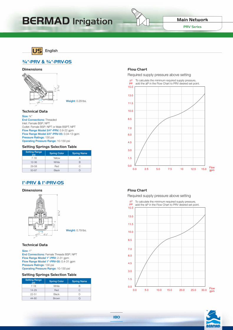
BERMAD IrrigationPRV Series
Main Network
180
Technical Data
Size: 1”End Connections: Female Threads BSP; NPTFlow Range Model 1”-PRV: 2-31 gpmFlow Range Model 1”-PRV-05: 0.4-31 gpmPressure Ratings: 130 psiOperating Pressure Range: 10-130 psi
Setting Springs Selection TableSetting Range
psi Spring Color Spring Name
7-18 White B
14-29 Red C
22-51 Black D
44-80 Brown Q
1"-PRV & 1"-PRV-05
¾"-PRV & ¾"-PRV-05
Technical DataSize: ¾” End Connections: Threaded Inlet: Female BSP; NPTOutlet: Female BSP; NPT or Male BSPT; NPTFlow Range Model 3/4”-PRV: 0.9-22 gpmFlow Range Model 3/4”-PRV-05: 0.04-13 gpmPressure Ratings: 130 psiOperating Pressure Range: 10-130 psi
Setting Springs Selection TableSetting Range
psi Spring Color Spring Name
7-18 Yellow A
12-36 White B
29-58 Red C
50-87 Black D
Flow Chart
Required supply pressure above setting
0.0
1.5
3.0
4.5
6.0
7.0
8.5
10.0
11.5
13.0
15.0
Flowgpm0.0 5.0 10.0 15.0 20.0 25.0
∆Ppsi
30.0
To calculate the minimum required supply pressure, add the ΔP in the Flow Chart to PRV desired set point.
Flow Chart
Required supply pressure above setting
0.0
1.5
3.0
4.5
6.0
7.0
8.5
10.0
11.5
13.0
15.0
Flowgpm0.0 2.5 5.0 7.5 10 12.5
∆Ppsi
15.0
To calculate the minimum required supply pressure, add the ΔP in the Flow Chart to PRV desired set point.
Dimensions
29 /16” 41/2”
13 /4”
6 5 /1
6”
Weight: 0.79 lbs.
US English
Dimensions
Weight: 0.29 lbs.1¾”
11 /1
6” 3
15/16
”
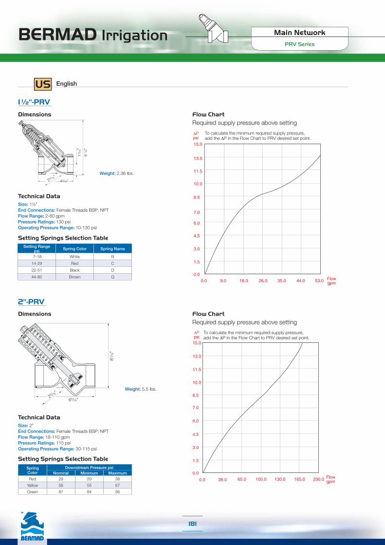
BERMAD IrrigationPRV Series
Main Network
181
43/16”
Technical DataSize: 1½” End Connections: Female Threads BSP; NPTFlow Range: 2-80 gpmPressure Ratings: 130 psiOperating Pressure Range: 10-130 psi
Setting Springs Selection TableSetting Range
psi Spring Color Spring Name
7-18 White B
14-29 Red C
22-51 Black D
44-80 Brown Q
Flow ChartRequired supply pressure above setting
0.0
1.5
3.0
4.5
6.0
7.0
8.5
10.0
11.5
13.0
15.0
∆Ppsi
Flowgpm0.0 9.0 18.0 26.0 35.0 44.0 53.0
To calculate the minimum required supply pressure, add the ΔP in the Flow Chart to PRV desired set point.
Technical DataSize: 2” End Connections: Female Threads BSP; NPTFlow Range: 18-110 gpmPressure Ratings: 115 psiOperating Pressure Range: 30-115 psi
Flow ChartRequired supply pressure above setting
Flowgpm0.0 35.0 65.0 100.0 130.0 200.0165.0
0.0
1.5
3.0
4.5
6.0
7.0
8.5
10.0
11.5
13.0
15.0
∆Ppsi
To calculate the minimum required supply pressure, add the ΔP in the Flow Chart to PRV desired set point.
2"-PRV
1½"-PRV
Spring Color
Downstream Pressure psiNominal Minimum Maximum
Red 29 29 38
Yellow 58 55 67
Green 87 84 96
Setting Springs Selection Table
29 /16”
65/16”
81 /16”
Weight: 5.5 lbs.
Dimensions
29 /16”
13 /1
6”6
1 /8”
Weight: 2.36 lbs.
Dimensions
US English

Accessories
Accesso
ries

Acc
esso
ries
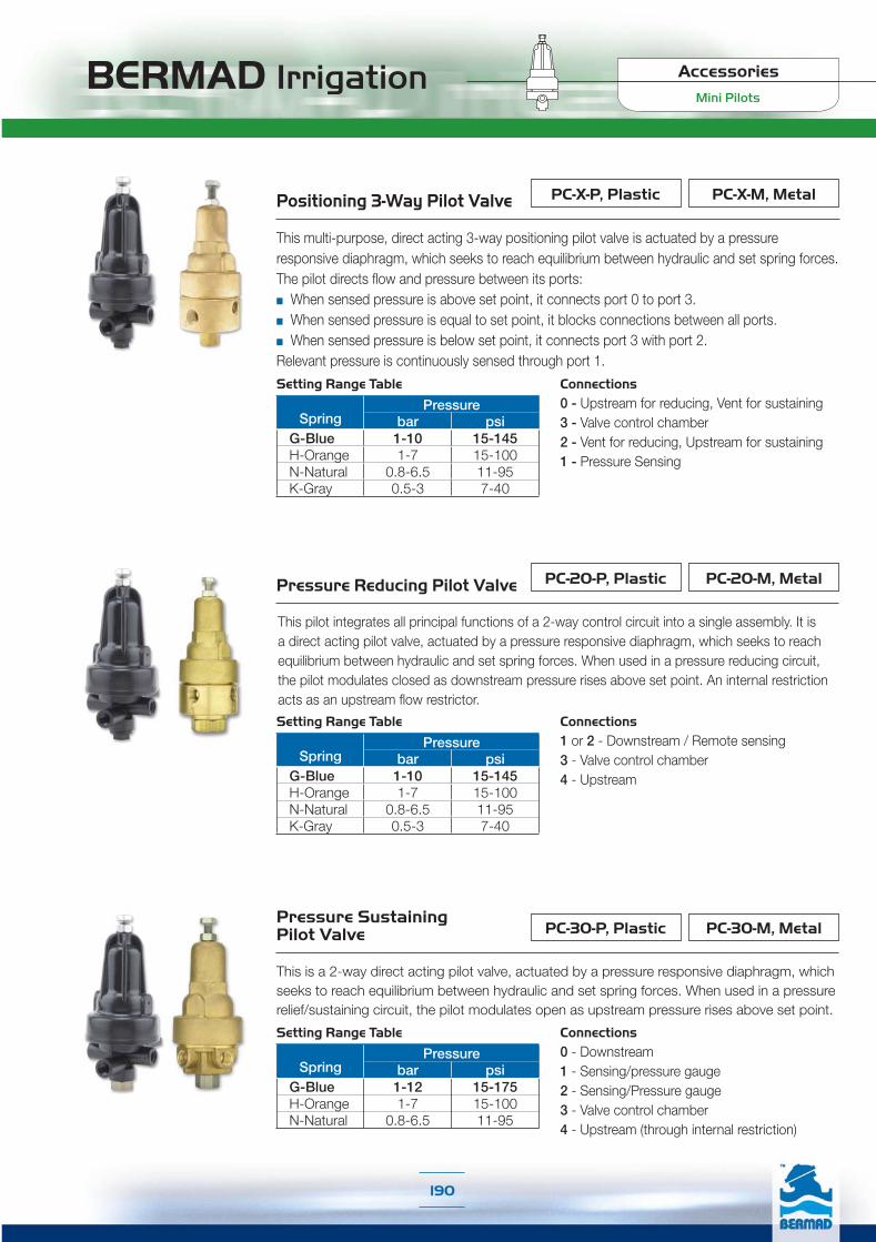
BERMAD Irrigation
190
Mini Pilots
Accessories
Positioning 3-Way Pilot Valve
This multi-purpose, direct acting 3-way positioning pilot valve is actuated by a pressure responsive diaphragm, which seeks to reach equilibrium between hydraulic and set spring forces.The pilot directs flow and pressure between its ports:■ When sensed pressure is above set point, it connects port 0 to port 3.■ When sensed pressure is equal to set point, it blocks connections between all ports.■ When sensed pressure is below set point, it connects port 3 with port 2.Relevant pressure is continuously sensed through port 1.
PC-X-M, MetalPC-X-P, Plastic
Connections0 - Upstream for reducing, Vent for sustaining3 - Valve control chamber2 - Vent for reducing, Upstream for sustaining1 - Pressure Sensing
PC-20-M, MetalPC-20-P, PlasticPressure Reducing Pilot Valve
This pilot integrates all principal functions of a 2-way control circuit into a single assembly. It is a direct acting pilot valve, actuated by a pressure responsive diaphragm, which seeks to reach equilibrium between hydraulic and set spring forces. When used in a pressure reducing circuit, the pilot modulates closed as downstream pressure rises above set point. An internal restriction acts as an upstream flow restrictor.
Connections1 or 2 - Downstream / Remote sensing3 - Valve control chamber4 - Upstream
Pressure Sustaining Pressure Sustaining Pilot ValvePilot Valve
This is a 2-way direct acting pilot valve, actuated by a pressure responsive diaphragm, which seeks to reach equilibrium between hydraulic and set spring forces. When used in a pressure relief/sustaining circuit, the pilot modulates open as upstream pressure rises above set point.
PC-30-M, MetalPC-30-P, Plastic
Connections0 - Downstream1 - Sensing/pressure gauge2 - Sensing/Pressure gauge3 - Valve control chamber4 - Upstream (through internal restriction)
Setting Range Table
SpringPressure
bar psiG-Blue 1-10 15-145H-Orange 1-7 15-100N-Natural 0.8-6.5 11-95K-Gray 0.5-3 7-40
Setting Range Table
SpringPressure
bar psiG-Blue 1-10 15-145H-Orange 1-7 15-100N-Natural 0.8-6.5 11-95K-Gray 0.5-3 7-40
Setting Range Table
SpringPressure
bar psiG-Blue 1-12 15-175H-Orange 1-7 15-100N-Natural 0.8-6.5 11-95

BERMAD Irrigation
191
Mini Pilots
Accessories
Pressure Reducing Servo Pilot Valve
This pilot combines all principal functions of a 2-way control circuit with elements of a 3-way control circuit. It is a direct acting pilot valve, actuated by a pressure responsive diaphragm, which seeks to reach equilibrium between hydraulic and set spring forces. A fully balanced trim ensures high accuracy and stability.
PC-S-M, MetalPC-S-P, Plastic
PC-70-P, PlasticPC-70-M, MetalPaddle Flow Rate Servo Pilot
This flow rate pilot combines all principal functions of a 2-way control circuit with elements of a 3-way control circuit. It is a direct acting pilot valve, actuated by a paddle that is positioned within the flow stream. Should demand rise above setting, the dynamic force of the increasing flow moves the paddle, which thereby pushes the pilot trim against the spring force. This causes the main valve to throttle closed, limiting system flow to pilot setting.
Connections0 - Upstream for reducing1 - Sensing2 - Downstream for reducing3 - Valve control chamber
Connections1 - Upstream2 - Downstream3 - Valve control chamber
Paddle Length Table
Quick Pressure Relief Pilot Valve
This pilot integrates all principal functions of a 2-Way control circuit in a single assembly. It is a direct acting pilots valve, actuated by a pressure responsive diaphragm, which seeks to reach equilibrium between hydraulic and set spring forces.The pilot opens at upstream pressure rise above set point. An integral restriction acts as an upstream flow restrictor smoothing valve closing and simplifying the control circuit.
PC-3Q-M, MetalPC-3Q-P, Plastic
Connections1 - Upstream2 - Pluged3 - Valve control chamber0 - Downstream
Setting Range Table
SpringPressure
bar psiG-Blue 1-12 15-175H-Orange 1-7 15-100
Setting Range Table
SpringPressure
bar psiK-Grey 0.5-3 7-40J-Green 0.2-1.7 3-25
Setting Range Table
SpringFlow Velocity
m/s f/sE-Purple 1-5 3.3-16.4
Valve size PaddleLength (mm)
PaddleLength (inch)
NumberLeavesinch DN
11/2 40 35 13/8 12 50 35 13/8 1
21/2 65 45 13/4 23R 80R 35 13/8 13 80 50 2 2
Valve size PaddleLength (mm)
PaddleLength (inch)
NumberLeavesinch DN
4R 100R 50 2 24 100 65 2½ 36 150 80 31/8 48 200 95 33/4 510 250 110 45/16 6

BERMAD Irrigation
192
Pressure Reducing Pilot Valve
Fully balanced trim ensures high accuracy and stability. When used in a pressure reducing circuit, the pilot throttles closed as downstream pressure rises above set point.
#2PB
High Sensitivity Pressure Reducing Pilot Valve with integral needle valve
This high sensitivity direct acting pilot specially suits very low set pressures or level control applications. It integrates all principal functions of a 2-way control circuit in a single assembly. An integral needle valve acts as an upstream flow restrictor as well as a closing speed control.
#82
#2Pressure Reducing Pilot Valve with integral needle valve
This pilot integrates all principal functions of a 2-way control circuit in a single assembly. An integral needle valve acts as an upstream flow restrictor as well as a closing speed control.
Pressure Reducing Pilot ValvesBERMAD Pressure Reducing Pilot Valves are direct acting pilot valves, actuated by a pressure responsive diaphragm, which tends to reach equilibrium with the set spring force. They continuously sense downstream or other pressure, which serves as an operating parameter, and throttle closed as sensed pressure rises above set point, controlling the main valve accordingly.
Pilots
Accessories
ConnectionsZ - Upstream A - Valve control chamber C - DownstreamF/D - External sensing/pressure gauge
ConnectionsZ - Upstream A - Valve control chamber C - DownstreamF/D - External sensing/pressure gauge
ConnectionsZ - Upstream A - Valve control chamber C - DownstreamSensing - For altitude control – still point at reservoir bottomFor pressure reducing – to valve downstream
Setting Range Table
SpringPressure
bar psiM 1-16 15-230N 0.8-6.5 11-95J* 0.2-1.7 3-25
Setting Range Table
SpringPressure
bar psi16 1-16 15-23010 0.8-10 11-15016* 2-30 30-43016* 2-45 30-650
Setting Range Table
CodePilot
Meter FeetM6 2-14 7-46M5 5-22 17-72M4 15-35 49-115M8 25-70 82-230
* For #2PB-D, differential sensing
* With high pressure setting kit

BERMAD Irrigation
193
Pressure Sustaining Pilot ValvesBERMAD Pressure Sustaining Pilot Valves are direct acting pilot valves, actuated by a pressure responsive diaphragm, which tends to reach equilibrium with the set spring force. They continuously sense upstream or other pressure, which serves as an operating parameter, and modulate open as sensed pressure rises above set point, controlling the main valve accordingly.
High Sensitivity Pressure Sustaining Pilot Valve with integral needle valve
This high sensitivity direct acting pilot specially suits very low set pressures or level sustaining applications. It integrates all principal functions of a 2-way control circuit in a single assembly. An integral needle valve acts as an upstream flow restrictor as well as a closing speed control.
#83
Pressure Sustaining Pilot Valve
When used in a pressure sustaining circuit, the pilot modulates open as upstream pressure rises above set point.
#3PB
Connections1 - Remote sensing or pressure gauge2 - Valve control chamber3 - Remote sensing or pressure gauge4 - DownstreamNote: Upstream pressure is connected to valve control chamber via a restriction.
#3Pressure Sustaining Pilot Valve with integral needle valve
This pilot integrates all principal functions of a 2-way control circuit in a single assembly. An integral needle valve acts as an upstream flow restrictor as well as a closing speed control.
ConnectionsZ - Upstream A - Valve control chamber C - Downstream F/D - External sensing/pressure gauge
ConnectionsZ - Upstream A - Valve control chamber C - DownstreamSensing - For level sustaining - still point at reservoir bottomFor pressure sustaining - valve upstream
Pilots
Accessories
Setting Range Table
SpringPressure
bar psiM 1-16 15-230N 0.8-6.5 11-95J* 0.2-1.7 3-25
Setting Range Table
SpringPressure
bar psi16 1-16 15-23010 0.8-10 11-15016* 2-30 30-43016* 2-45 30-650
* With high pressure setting kit
Setting Range Table
CodePilot
Meter FeetM6 2-14 7-46M5 5-22 17-72M4 15-35 49-115M8 25-70 82-230
* For #3PB-D, differential sensing

BERMAD Irrigation
194
Positioning Pilot Valves BERMAD multi-purpose, direct acting, 3-way positioning pilot valves are actuated by a pressure responsive diaphragm, which tends to reach equilibrium with the set spring force.The pilot directs flow and pressure between its ports:■ When sensed pressure is above set point, it connects port C to port 0.■ When sensed pressure is equal to set point, it blocks connections between all ports.■ When sensed pressure is below set point, it connects port C with ports A and Z.An integral needle valve restricts flow through port Z.
Positioning Pilot Valve
Suitable for Pressure Reducing Valves, Pressure Sustaining Valves, and Pressure Reducing & Sustaining Valves, the Positioning Pilot provides accurate and stable regulation, fully opening or closing the valve upon sensed pressure discrepancy from setting. The pilot can also serve as an Adjustable Hydraulic Relay (N.O. or N.C.) or Automatic Regulation Override (feature 09).
#X
Connections0 - Upstream for reducing, vent for sustainingC - Valve control chamberA/Z - Vent for reducing, upstream for sustainingF/D - Sensing/pressure gauge
Pilots
Accessories
Setting Range Table
SpringPressure
bar psi16 1-16 15-23010 0.8-10 11-150
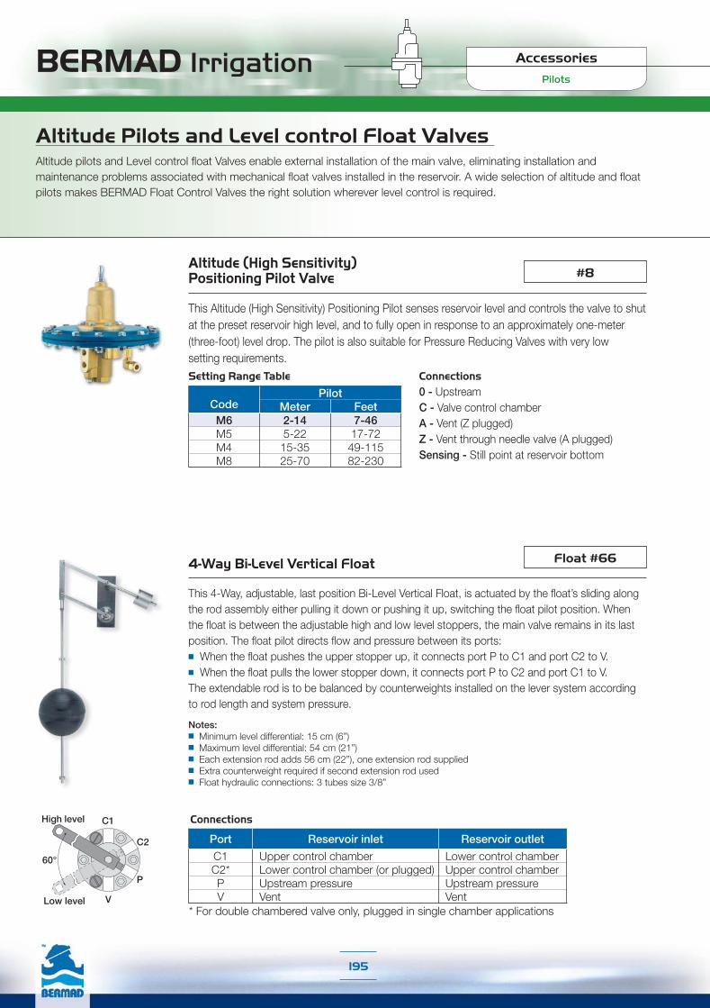
BERMAD Irrigation
195
Altitude (High Sensitivity) Positioning Pilot Valve
This Altitude (High Sensitivity) Positioning Pilot senses reservoir level and controls the valve to shut at the preset reservoir high level, and to fully open in response to an approximately one-meter (three-foot) level drop. The pilot is also suitable for Pressure Reducing Valves with very low setting requirements.
#8
Altitude Pilots and Level control Float Valves Altitude pilots and Level control float Valves enable external installation of the main valve, eliminating installation and maintenance problems associated with mechanical float valves installed in the reservoir. A wide selection of altitude and float pilots makes BERMAD Float Control Valves the right solution wherever level control is required.
Connections0 - Upstream C - Valve control chamberA - Vent (Z plugged)Z - Vent through needle valve (A plugged)Sensing - Still point at reservoir bottom
Float #664-Way Bi-Level Vertical Float
This 4-Way, adjustable, last position Bi-Level Vertical Float, is actuated by the float’s sliding along the rod assembly either pulling it down or pushing it up, switching the float pilot position. When the float is between the adjustable high and low level stoppers, the main valve remains in its last position. The float pilot directs flow and pressure between its ports:■ When the float pushes the upper stopper up, it connects port P to C1 and port C2 to V.■ When the float pulls the lower stopper down, it connects port P to C2 and port C1 to V. The extendable rod is to be balanced by counterweights installed on the lever system accordingto rod length and system pressure.
Notes:■ Minimum level differential: 15 cm (6”)■ Maximum level differential: 54 cm (21”)■ Each extension rod adds 56 cm (22”), one extension rod supplied■ Extra counterweight required if second extension rod used■ Float hydraulic connections: 3 tubes size 3/8”
C1
C2
P
V
60°
High level
Low level
Pilots
Accessories
Setting Range Table
CodePilot
Meter FeetM6 2-14 7-46M5 5-22 17-72M4 15-35 49-115M8 25-70 82-230
Port Reservoir inlet Reservoir outlet
C1 Upper control chamber Lower control chamberC2* Lower control chamber (or plugged) Upper control chamberP Upstream pressure Upstream pressureV Vent Vent
Connections
* For double chambered valve only, plugged in single chamber applications

Notes:■ To get a 3-way controlled N.C. main valve, use a N.O. 3-way solenoid and vice versa. ■ S-400 models include bigger orifice diameter than S-390, which means quicker action. ■ The S-982 and S-985 actuators are isolated from the water.■ Actuators with the suffix 'R' are suitable to areas with high lightning's probability■ Calculate wires cross section in accordance to: ❏ System pressure conditions ❏ Solenoids consumption, quantity & distance
BERMAD Irrigation
196
Solenoids
Accessories
Solenoid Selection GuideThe automation design is an integral part of the irrigation project design file. In order to help in the selection process of the most suitable solenoids for a given project, several questions need to be answered. Following the chart below, will guide you to the desired solenoid model. Please check selected solenoid specifications in the following pages, to confirm its suitability to the project conditions.
Please refer to the following questions for best navigation:■ Operating Current: Alternating Current (AC) or Direct Current (DC)■ Solenoid Logic: 2-Way or 3-Way■ Actuator Type: Continuous Current or Latching■ Solenoid Normal Position: Normally Open or Normally Closed■ Controller Requirements: Two Wires or Three Wires
AC AC (24V Only) (24V Only)
DCDC
AC or DCAC or DC
Continuous Continuous Latching
2 Wires2 Wires 3 Wires 3 Wires
S-985-3L-3W-S-985-3L-3W-12V/DC-BB 12V/DC-BB
3-Way 3-Way 3-Way 3-Way 2-Way 2-Way
S-982-2L-3W-S-982-2L-3W-12V/DC-BB 12V/DC-BB
S-392-2L-2W-S-392-2L-2W-9V/DC 9V/DC
S-402-2L-3W-S-402-2L-3W-9V/DC-BB 9V/DC-BB
S-400-3W-R-S-400-3W-R-24V/AC-NO 24V/AC-NO
S-400-3W-D-S-400-3W-D-24V/AC-NO 24V/AC-NO
3-Way 3-Way 2-Way2-Way
N.C. Only N.C. Only N.C. N.C. N.O. N.O.
S-390-2W-D-S-390-2W-D-24V/AC-NC 24V/AC-NC
S-390-3W-D-S-390-3W-D-24V/AC-NO 24V/AC-NO
S-390-2W-R-S-390-2W-R-24V/AC-NC 24V/AC-NC
S-390-3W-R-S-390-3W-R-24V/AC-NO 24V/AC-NO
S-400-3W-R-S-400-3W-R-24V/AC-NC 24V/AC-NC
S-400-3W-D-S-400-3W-D-24V/AC-NC 24V/AC-NC
S-390-3W-R-S-390-3W-R-24V/AC-NC 24V/AC-NC
S-390-3W-S-390-3W-12V/DC-NC 12V/DC-NC
S-400-3W-S-400-3W-12V/DC-NO 12V/DC-NO
S-390-3W-S-390-3W-24V/DC-NC 24V/DC-NC
S-400-3W-S-400-3W-24V/DC-NO 24V/DC-NO
3-Way3-Way2-Way2-Way
N.C. Only N.C. Only N.O. N.O. N.C. N.C.
S-390-2W-S-390-2W-12V/DC-N 12V/DC-N
S-390-3W-S-390-3W-12V/DC-NO 12V/DC-NO
S-390-2W-S-390-2W-24V/DC-NC 24V/DC-NC
S-390-3W-S-390-3W-24V/DC-NO 24V/DC-NO
2 Wires or 2 Wires or 3 Wires3 Wires
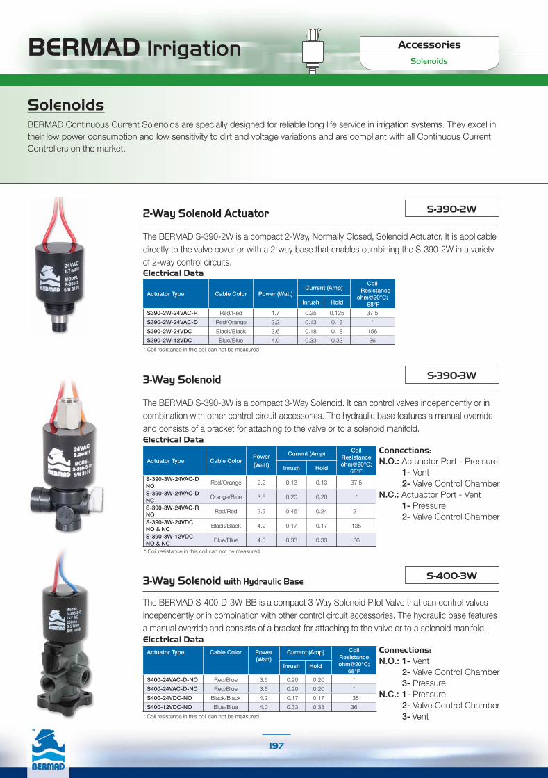
BERMAD Irrigation
197
SolenoidsBERMAD Continuous Current Solenoids are specially designed for reliable long life service in irrigation systems. They excel in their low power consumption and low sensitivity to dirt and voltage variations and are compliant with all Continuous Current Controllers on the market.
Solenoids
Accessories
2-Way Solenoid Actuator
3-Way Solenoid
The BERMAD S-390-3W is a compact 3-Way Solenoid. It can control valves independently or in combination with other control circuit accessories. The hydraulic base features a manual override and consists of a bracket for attaching to the valve or to a solenoid manifold.
S-390-3W
Actuator Type Cable ColorPower(Watt)
Current (Amp) CoilResistanceohm@20°C;
68°FInrush Hold
S-390-3W-24VAC-DNO
Red/Orange 2.2 0.13 0.13 37.5
S-390-3W-24VAC-DNC
Orange/Blue 3.5 0.20 0.20 *
S-390-3W-24VAC-R NO
Red/Red 2.9 0.46 0.24 21
S-390-3W-24VDCNO & NC
Black/Black 4.2 0.17 0.17 135
S-390-3W-12VDCNO & NC
Blue/Blue 4.0 0.33 0.33 36
3-Way Solenoid with Hydraulic Base
The BERMAD S-400-D-3W-BB is a compact 3-Way Solenoid Pilot Valve that can control valves independently or in combination with other control circuit accessories. The hydraulic base features a manual override and consists of a bracket for attaching to the valve or to a solenoid manifold.
S-400-3W
Actuator Type Cable Color Power(Watt)
Current (Amp) Coil Resistanceohm@20°C;
68°FInrush Hold
S400-24VAC-D-NO Red/Blue 3.5 0.20 0.20 *
S400-24VAC-D-NC Red/Blue 3.5 0.20 0.20 *
S400-24VDC-NO Black/Black 4.2 0.17 0.17 135
S400-12VDC-NO Blue/Blue 4.0 0.33 0.33 36
The BERMAD S-390-2W is a compact 2-Way, Normally Closed, Solenoid Actuator. It is applicable directly to the valve cover or with a 2-way base that enables combining the S-390-2W in a variety of 2-way control circuits.
S-390-2W
Actuator Type Cable Color Power (Watt)Current (Amp)
Coil Resistanceohm@20°C;
68°FInrush Hold
S390-2W-24VAC-R Red/Red 1.7 0.25 0.125 37.5
S390-2W-24VAC-D Red/Orange 2.2 0.13 0.13 *
S390-2W-24VDC Black/Black 3.6 0.18 0.18 156
S390-2W-12VDC Blue/Blue 4.0 0.33 0.33 36
* Coil resistance in this coil can not be measured
* Coil resistance in this coil can not be measured
* Coil resistance in this coil can not be measured
Electrical Data
Electrical Data
Electrical Data
Connections:N.O.: Actuactor Port - Pressure 1- Vent 2- Valve Control ChamberN.C.: Actuactor Port - Vent 1- Pressure 2- Valve Control Chamber
Connections:N.O.: 1- Vent 2- Valve Control Chamber 3- PressureN.C.: 1- Pressure 2- Valve Control Chamber 3- Vent
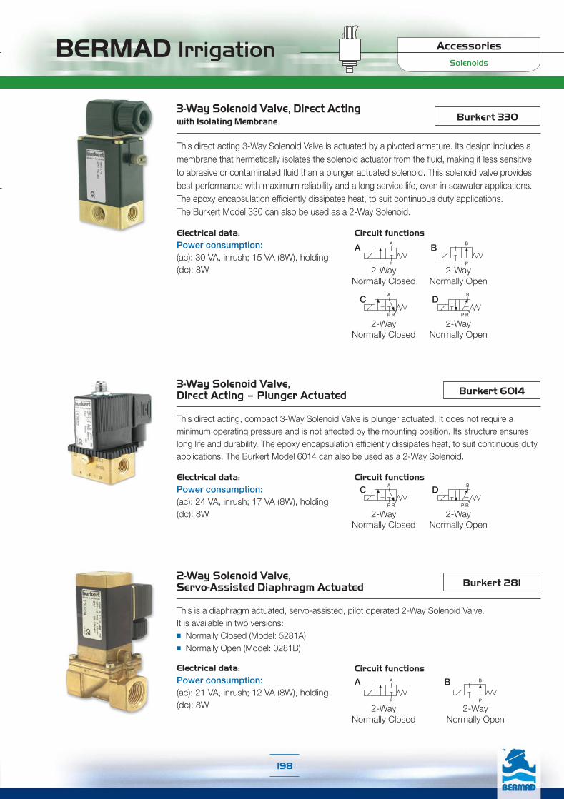
BERMAD Irrigation
198
Solenoids
Accessories
2-Way Solenoid Valve, Servo-Assisted Diaphragm Actuated
This is a diaphragm actuated, servo-assisted, pilot operated 2-Way Solenoid Valve.It is available in two versions:■ Normally Closed (Model: 5281A)■ Normally Open (Model: 0281B)
Burkert 281
3-Way Solenoid Valve, Direct Acting – Plunger Actuated
This direct acting, compact 3-Way Solenoid Valve is plunger actuated. It does not require a minimum operating pressure and is not affected by the mounting position. Its structure ensures long life and durability. The epoxy encapsulation efficiently dissipates heat, to suit continuous duty applications. The Burkert Model 6014 can also be used as a 2-Way Solenoid.
Burkert 6014
Electrical data:Power consumption:(ac): 24 VA, inrush; 17 VA (8W), holding(dc): 8W
Circuit functions
Electrical data:Power consumption:(ac): 21 VA, inrush; 12 VA (8W), holding(dc): 8W
3-Way Solenoid Valve, Direct Acting with Isolating Membrane
This direct acting 3-Way Solenoid Valve is actuated by a pivoted armature. Its design includes a membrane that hermetically isolates the solenoid actuator from the fluid, making it less sensitive to abrasive or contaminated fluid than a plunger actuated solenoid. This solenoid valve provides best performance with maximum reliability and a long service life, even in seawater applications. The epoxy encapsulation efficiently dissipates heat, to suit continuous duty applications. The Burkert Model 330 can also be used as a 2-Way Solenoid.
Burkert 330
Electrical data:Power consumption:(ac): 30 VA, inrush; 15 VA (8W), holding (dc): 8W
Circuit functions
Circuit functions
2-WayNormally Closed
2-WayNormally Open
2-WayNormally Closed
2-WayNormally Open
2-WayNormally Closed
2-WayNormally Open
2-WayNormally Closed
2-WayNormally Open

BERMAD Irrigation
199
Latching Solenoids
Accessories
Latching SolenoidsBERMAD Latching Solenoids are specially designed for reliable long life service in irrigation systems controlled by Battery Operated Controllers. The Latching Solenoids consume power only when switching positions, using a very short electric impulse. This prolongs life of batteries and enables solar recharging.
Magnetic Latch Solenoid Actuator, 2-Way, 9VDC Latch, 2- Leads
The BERMAD Model S-392-2W is a compact 2-Way Latching Solenoid Actuator. It is applicable directly to the valve cover or with a 2-way base that enables combining it in variety of 2-way control circuits.
S-392-2W
Electrical Data:Voltage Range: 6-20 VDCCoil Resistance: 6ΩCoil Inductance: 90 mHPulse Width: 20-100 mSec.Required Capacitor: 4700µFOperation Modes (electrical connections):+Red & -Black: Latch Position+Black & -Red: Released Position
Magnetic Latch Solenoid with Hydraulic Base 3-Way, 9VDC Latch, 2- Leads
The BERMAD Model S-402-3W can control valves independently or in combination with other control circuit accessories. The hydraulic base features a manual override and consists of a bracket for attaching to the valve or to a solenoid manifold.
S-402-3W
Electrical Data:Voltage Range: 9-40 VDCCoil Resistance: 6ΩCoil Inductance: 90 mHPulse Width: 20-100 mSecRequired Capacitor: 4700µFOperation Modes (electrical connentions):+Red & -Black: Solenoid vents+Black & - Red: Solenoid pressurizes
Pressure & Flow Data:Operating Pressure Range: 0-10 barBase Orifice Diameter: 2.2 mmBase Flow Factor: Kv = 0.12 m3/h @ 1 bar ΔP; Cv= 0.14 GPM @1 psi ΔP
Connections:1- Vent2- Valve Control Chamber3- Pressure

BERMAD Irrigation
200
Dry Magnetic Latch Solenoid with Isolating Membrane & Hydraulic Base3-Way, 12VDC Latch, 2- Leads
The BERMAD Model S-982-3W actuator is neutralized from water damage by a membrane, which hermetically isolates it from the water. It can control valves independently or in combination with other control circuit accessories. The hydraulic base features a manual override and consists of a bracket for attaching to the valve or to a solenoid manifold.
S-982-3W
Solenoid Valve for Remote Terminal Unit (RTU)
BERMAD’s Solenoid Valve for Remote Terminal Unit (RTU) is a solenoid pilot valve controller used in remote control irrigation via radio or cable. It is a battery operated, self-contained unit, suitable for use in irrigation applications with a master radio control system.Note: RTU units can be purchased only through Motorola® irrigation control department.
For further details please contact: [email protected]
Electrical Data:Voltage Range: 12-50 VDCCoil Resistance: 4.2ΩPulse Width: 20-100 mSec.Required Capacitor: 4700µFOperation Modes (electrical connections):+ Red & - Black: Solenoid vents+ Black & - Red: Solenoid pressurizes
Pressure & Flow Data:Operating Pressure Range: 0-10 barBase Orifice Diameter: 2.2 mmBase Flow Factor: Pressure port Kv = 0.12 m3/h @ 1 bar ΔP Cv = 0.14 GPM @1 psi ΔPExhaust port Kv = 0.14 m3/h @ 1 bar ΔP Cv = 0.16 GPM @1 psi ΔP
Dry Magnetic Latch Solenoid with Isolating Membrane & Hydraulic Base3-Way, 12VDC Latch, 3- Leads
The BERMAD Model S-985-3W actuator is neutralized from water damage by a membrane, which hermetically isolates it from the water. It can control valves independently or in combination with other control circuit accessories. The hydraulic base features a manual override and consists of a bracket for attaching to the valve or to a solenoid manifold.
S-985-3W
Electrical Data:Voltage Range: 12-50 VDCCoil Resistance: 2 Coils - 4.2Ω On; 7.5Ω OffPulse Width: 20-100 mSec.Required Capacitor: 4700µFOperation Modes (electrical connections):+ White: Fixed Common- Red: Solenoid vents- Black: Solenoid pressurizes
Pressure & Flow Data:Operating Pressure Range: 0-10 barBase Orifice Diameter: 2.2 mmBase Flow Factor: Pressure port Kv = 0.12 m3/h @ 1 bar ΔP Cv = 0.14 GPM @1 psi ΔPExhaust port Kv = 0.14 m3/h @ 1 bar ΔP Cv = 0.16 GPM @1 psi ΔP
Latching Solenoids
Accessories
Connections:1- Vent 2- Valve Control Chamber 3- Pressure
Connections:1- Vent 2- Valve Control Chamber 3- Pressure
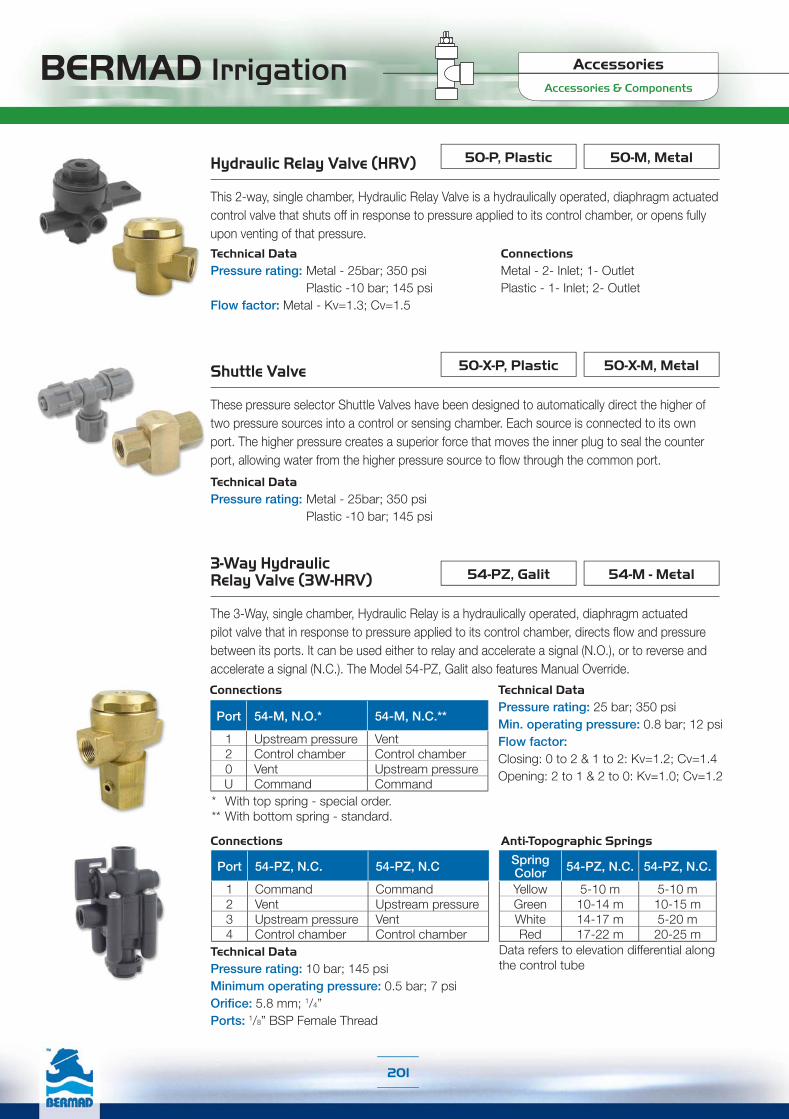
BERMAD Irrigation
201
Accessories & Components
Accessories
3-Way Hydraulic Relay Valve (3W-HRV)
The 3-Way, single chamber, Hydraulic Relay is a hydraulically operated, diaphragm actuated pilot valve that in response to pressure applied to its control chamber, directs flow and pressure between its ports. It can be used either to relay and accelerate a signal (N.O.), or to reverse and accelerate a signal (N.C.). The Model 54-PZ, Galit also features Manual Override.
54-M - Metal54-PZ, Galit
Shuttle Valve
These pressure selector Shuttle Valves have been designed to automatically direct the higher of two pressure sources into a control or sensing chamber. Each source is connected to its own port. The higher pressure creates a superior force that moves the inner plug to seal the counter port, allowing water from the higher pressure source to flow through the common port.
50-X-M, Metal50-X-P, Plastic
Technical DataPressure rating: Metal - 25bar; 350 psi Plastic -10 bar; 145 psi
Technical DataPressure rating: 25 bar; 350 psi Min. operating pressure: 0.8 bar; 12 psi Flow factor:Closing: 0 to 2 & 1 to 2: Kv=1.2; Cv=1.4Opening: 2 to 1 & 2 to 0: Kv=1.0; Cv=1.2
Technical DataPressure rating: 10 bar; 145 psiMinimum operating pressure: 0.5 bar; 7 psi Orifice: 5.8 mm; 1/4”Ports: 1/8” BSP Female Thread
Hydraulic Relay Valve (HRV)
This 2-way, single chamber, Hydraulic Relay Valve is a hydraulically operated, diaphragm actuated control valve that shuts off in response to pressure applied to its control chamber, or opens fully upon venting of that pressure.
50-M, Metal50-P, Plastic
Technical DataPressure rating: Metal - 25bar; 350 psi Plastic -10 bar; 145 psiFlow factor: Metal - Kv=1.3; Cv=1.5
ConnectionsMetal - 2- Inlet; 1- Outlet Plastic - 1- Inlet; 2- Outlet
54-PZ, N.C. 54-PZ, N.O. 54-PZ, N.C. 54-PZ, N.O.
Anti-Topographic Springs
Data refers to elevation differential along the control tube
SpringColor 54-PZ, N.C. 54-PZ, N.C.
Yellow 5-10 m 5-10 mGreen 10-14 m 10-15 mWhite 14-17 m 5-20 mRed 17-22 m 20-25 m
Connections
Port 54-PZ, N.C. 54-PZ, N.C
1 Command Command2 Vent Upstream pressure3 Upstream pressure Vent4 Control chamber Control chamber
Connections
Port 54-M, N.O.* 54-M, N.C.**
1 Upstream pressure Vent2 Control chamber Control chamber0 Vent Upstream pressureU Command Command
* With top spring - special order.** With bottom spring - standard.

BERMAD Irrigation
202
Accessories & Components
Accessories
5W-SOPAMV Sequential Shut-Off Pilot
This 5-Way Shut-Off Pilot Valve directs pressure and flow between its ports:■ In Set Position the 5W-SOP spool is pushed closed, thereby hydraulically
connecting ports P to C2 and C1 to V1.■ In Normal Position the 5W-SOP spool is returned by the spring action,
hydraulically connecting ports P to C1 and C2 to V2.
3W-SOP-SAMV Shut-Off Pilot with Pump Shut-Off Electrical Switch
This 3-Way Shut-off Pilot Valve directs pressure and flow between its ports:■ In Set Position the 3W-SOP-S spool is pushed closed, thereby hydraulically
connecting ports C1 to V1.■ In Normal Position the 3W-SOP-S spool is returned by the spring action,
hydraulically connecting port P to C1.The spool activates the electric Change-Over Switch, which turns off the system’s pump after delivery of the preset quantity of water.
AMV Shut-Off Pilot 3W-SOP
This 3-Way Shut-Off Pilot Valve is a spring-return, flap actuated pilot valve that in response to pushing a spool against a spring, directs pressure and flow between its ports: ■ In Set Position the 3W-SOP spool is pushed closed, thereby hydraulically
connecting ports C and V.■ In Normal Position the 3W SOP spool is returned by the spring action,
hydraulically connecting ports P and C.By manually turning the AMV setting knob, the flap is actuated to push the spool. After delivering the preset quantity of water, the flap slips into a groove in the turning control head mechanism, allowing the spool to return to Normal Position. Connections:P - UpstreamC - AMV Control ChamberV - Vent
Connections:P - UpstreamC1 - AMV Control ChamberV1 - Previous AMV ( Vent for first AMV)
C2 - Next AMV (Plugged for last AMV)V2 - Vent
Connections:P - UpstreamC1 - AMV Control ChamberV1 -VentC2 -Plugged
Switch Data:Change Over 5-250V Electrical Connections N.O. or N.C.
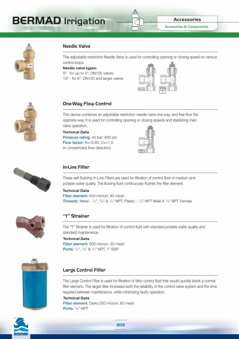
BERMAD Irrigation
203
Acessories & Components
Accessories
Needle Valve
This adjustable restriction Needle Valve is used for controlling opening or closing speed on various control loops.Needle valve types: 5º - for up to 4”; DN100 valves15º - for 6”; DN150 and larger valves
One-Way Flow Control
This device combines an adjustable restriction needle valve one way, and free flow the opposite way. It is used for controlling opening or closing speeds and stabilizing main valve operation.
Technical DataPressure rating: 40 bar; 600 psiFlow factor: Kv=0.85; Cv=1.0 (in unrestricted flow direction)
“Y” Strainer
The "Y" Strainer is used for filtration of control fluid with standard potable water quality and standard maintenance.
Technical DataFilter element: 500 micron; 35 mesh Ports: 1/4”, 3/8” & 1/2” NPT, 1” BSP
In-Line Filter
These self-flushing In-Line Filters are used for filtration of control fluid of medium and potable water quality. The flowing fluid continuously flushes the filter element.
Technical DataFilter element: 400 micron; 40 meshThreads: Metal - 1/4”, 3/8” & 1/2” NPT; Plastic - 1/4” NPT Male X 1/8” NPT Female
Large Control Filter
The Large Control Filter is used for filtration of dirty control fluid that would quickly block a normal filter element. This larger filter increases both the reliability of the control valve system and the time required between maintenance, while minimizing faulty operation.Technical DataFilter element: Disks 250 micron; 60 mesh Ports: 3/8” NPT

BERMAD Irrigation
204
Accessories Components
Accessories
Check Valve
These spring loaded, non-return valves provide free flow in one direction and prevent flow in the opposite direction. They can be installed in any orientation.
Technical DataPressure rating: 20.5 bar; 300 psiPorts: 1/4”, 3/8” & 1/2” NPT3/4”, 1” & 11/2” BSP
2-Way Ball Valve
This Ball Valve provides quick and easy on/off manual control for isolating, manual release, and draining.
Technical DataPressure rating: 40 bar; 600 psi - 1/4” to 3/4”35 bar; 500 psi - 1” to 2”Ports: 1/4”, 3/8” & 1/2” NPT3/4”, 1”, 11/2” & 2” BSP
3-Way Ball Valve
This 3-Way Ball Valve is used as a pilot providing quick and easy, 2-position on/off manual control.
Technical DataPressure rating: 27.5 bar; 400 psiPorts: 1/4”, 3/8” & 1/2” NPT
Manometer Ball Valve
This vented 2-Way Ball Valve provides quick and easy manual isolating and venting of either pressure gauges or any other pressurized control loop components.
Technical DataPressure rating: 16 bar; 230 psiPorts: 1/8”, 1/4” & 3/8” NPT

BERMAD Irrigation
205
System Components
Accessories
Orifice Plate Assembly
When an Orifice Plate Assembly is used as an integral part of a flow control valve control circuit, it provides the differential pressure (P) to power the flow control pilot. The opening and closing of the pilot causes the flow control valve to throttle accordingly. Total head loss across the valve is reduced by locating sensing ports close to the orifice plate, to sense downstream pressure before it recovers. The orifice plate’s internal diameter is calculated and machined according to valve size and required flow limitation.
L.P. portD
1/8” NPT
H.P. portd
X Z
Orifice Assembly
When an Orifice Assembly is used as an integral part of a flow control valve control circuit, it provides a Pressure Differential (P) in direct proportion to the flow rate.This P is sensed by the flow control pilot, powering it to open or close. The opening and closing of the pilot causes the flow control valve to throttle accordingly. The orifice’s internal diameter is calculated and machined according to valve size and required flow limitation.
Dimensions
Dimensions
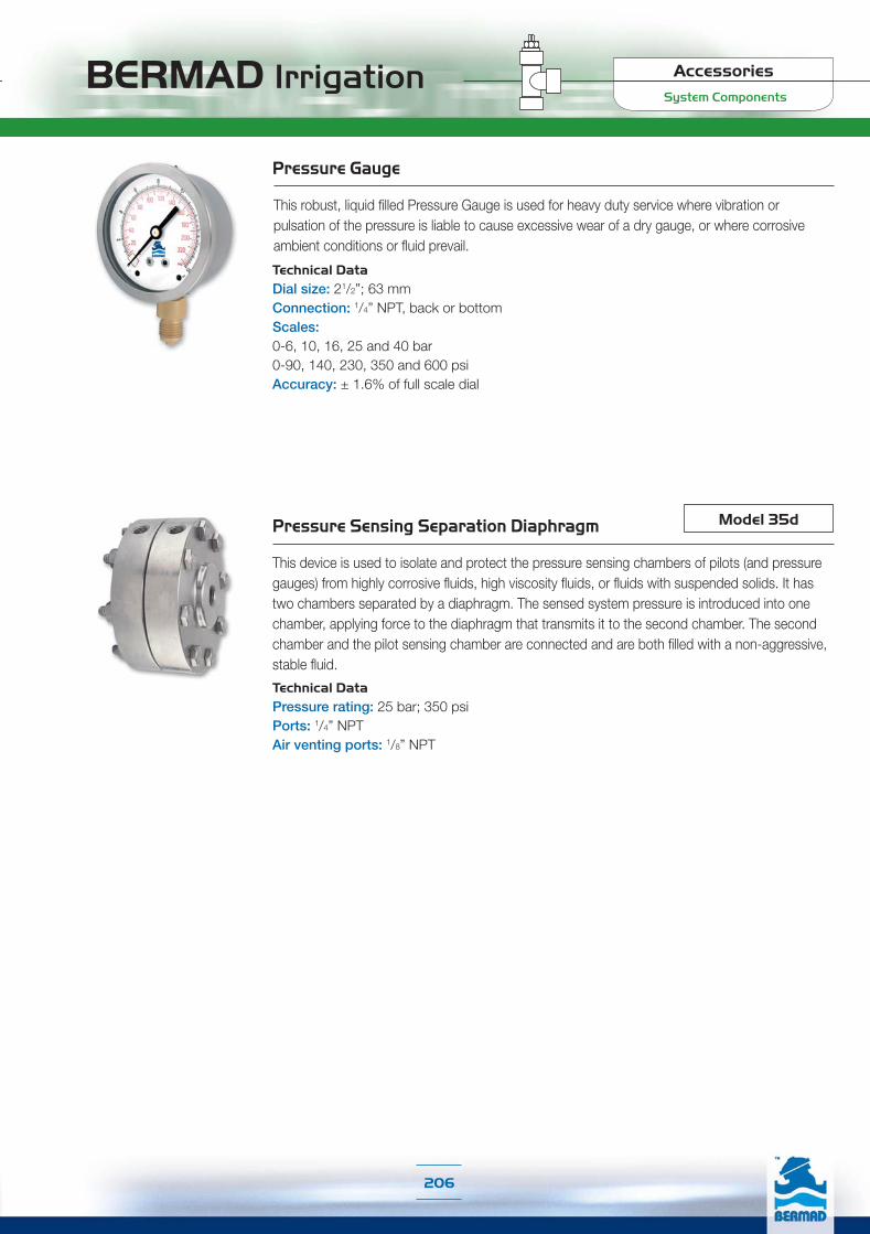
BERMAD Irrigation
206
System Components
Accessories
Pressure Gauge
This robust, liquid filled Pressure Gauge is used for heavy duty service where vibration or pulsation of the pressure is liable to cause excessive wear of a dry gauge, or where corrosive ambient conditions or fluid prevail.
Technical DataDial size: 21/2”; 63 mmConnection: 1/4” NPT, back or bottomScales: 0-6, 10, 16, 25 and 40 bar0-90, 140, 230, 350 and 600 psiAccuracy: ± 1.6% of full scale dial
Pressure Sensing Separation Diaphragm
This device is used to isolate and protect the pressure sensing chambers of pilots (and pressure gauges) from highly corrosive fluids, high viscosity fluids, or fluids with suspended solids. It has two chambers separated by a diaphragm. The sensed system pressure is introduced into one chamber, applying force to the diaphragm that transmits it to the second chamber. The second chamber and the pilot sensing chamber are connected and are both filled with a non-aggressive, stable fluid.
Model 35d
Technical DataPressure rating: 25 bar; 350 psiPorts: 1/4” NPTAir venting ports: 1/8” NPT

BERMAD Irrigation
207
System Components
Accessories
Strainer
The BERMAD 70F Strainer is designed to remove foreign matter such as stones, sticks, etc. from the pipeline. It is recommended to install the Strainer upstream from control valves, flow meters and other system appliances. High Pressure Strainer Model 80F is also available.close to the orifice plate, to sense downstream pressure before it recovers. The orifice plate’s internal diameter is calculated and machined according to valve size and required flow limitation.
Model 70F
Technical DataPatterns: “Y” (globe) & angleSize Range: 40-500 mm; 11/2 - 20” End Connections (Pressure Ratings): Flanged: ISO PN16, PN25; ANSI Class 150, 300Threaded: BSP or NPT Others: Available on requestStandard Materials:Body: Ductile IronCover: SteelSeals: NBRCoating: Polyester Powder, RAL 6017 (Green)
Basket Hole Diameter (mm)Stainless Steel 304 (Standard)
Stainless Steel 316 (Optional)
Dimensions & Weight
Flow Chart