PDE2612TCUK -JOFBS DUVBUPST %[NKPFGT HQTEGU...
13
Cylinder Cylinder Piston rod Cushioning Air con- Connection Flexible Porting designation bore area dia. area thread length sump- thread tubing dimension tion 2) Push-in mm cm 2 mm cm 2 mm litre mm 1) 32 8,0 12 1,1 M10x1,25 17 0,105 G1/8 4 or 6 1) 40 12,6 16 2,0 M12x1,25 19 0,162 G1/4 4 or 6 1) 50 19,6 20 3,1 M16x1,5 20 0,253 G1/4 8 or 10 1) 63 31,2 20 3,1 M16x1,5 23 0,414 G3/8 8 or 10 1) 80 50,3 25 4,9 M20x1,5 23 0,669 G3/8 - 1) 100 78,5 25 4,9 M20x1,5 27 1,043 G1/2 - 1) 125 122,7 32 8,0 M27x2 30 1,662 G1/2 Cylinder Total mass (kg) Supplement mass (kg) Total mass (kg) designation at 0 mm stroke for rod locking Supplement per 10 mm stroke Standard Tie-Rod Clean/Flex All variants Standard Tie-Rod Clean/Flex Cylinder Mass moving parts(kg) designation at 0 mm strokeSupplement per 10 mm stroke All variants All variants 1) Stroke 2) Free air consumption per 10 mm stroke for a double stroke at 6 bar pist. rod mm cm 2 1,0 2,0 3,0 4,0 5,0 6,0 7,0 8,0 9,0 10,0 + 8,0 80 161 241 322 402 563 643 724 804 - 6,9 69 138 207 276 346 415 484 553 622 691 40/16 + 12,6 126 251 377 503 628 754 880 1005 1131 1257 - 10,6 106 212 318 424 530 742 848 954 1060 50/20 + 19,6 196 393 589 785 982 1178 1374 1571 1767 1963 - 16,5 165 330 495 660 825 990 1155 1319 1484 1649 + 31,2 312 623 935 1247 1559 1870 2182 2494 2806 3117 - 28,0 280 561 841 1121 1402 1682 1962 2242 2523 2803 80/25 + 50,3 503 1005 1508 2011 2513 3519 4021 4524 5027 - 45,4 454 907 1361 1814 2268 2721 3175 3629 4082 4536 100/25 + 78,5 785 1571 2356 3142 3927 4712 5498 6283 7069 7854 - 73,6 736 1473 2209 2945 3682 4418 5154 5890 6627 7363 + 122,7 1227 2454 3682 4909 6136 8590 9817 11045 12272 - 114,7 1147 2294 3440 4587 5734 6881 8027 9174 10321 11468 Select a theoretical force 50-100% larger than the force required + = Outward stroke - = Return stroke C 67 Pneumatic Division - Europe PDE2612TCUK
Transcript of PDE2612TCUK -JOFBS DUVBUPST %[NKPFGT HQTEGU...

Cylinder Cylinder Piston rod Cushioning Air con- Connection Flexible Porting designation bore area dia. area thread length sump- thread tubing dimension tion2) Push-in mm cm2 mm cm2 mm litre mm
1) 32 8,0 12 1,1 M10x1,25 17 0,105 G1/8 4 or 61) 40 12,6 16 2,0 M12x1,25 19 0,162 G1/4 4 or 61) 50 19,6 20 3,1 M16x1,5 20 0,253 G1/4 8 or 101) 63 31,2 20 3,1 M16x1,5 23 0,414 G3/8 8 or 101) 80 50,3 25 4,9 M20x1,5 23 0,669 G3/8 -1) 100 78,5 25 4,9 M20x1,5 27 1,043 G1/2 -1) 125 122,7 32 8,0 M27x2 30 1,662 G1/2
Cylinder Total mass (kg) Supplement mass (kg) Total mass (kg) designation at 0 mm stroke for rod locking Supplement per 10 mm stroke Standard Tie-Rod Clean/Flex All variants Standard Tie-Rod Clean/Flex
Cylinder Mass moving parts(kg) designation at 0 mm stroke Supplement per 10 mm stroke All variants All variants
1) Stroke
2) Free air consumption per 10 mm stroke for a double stroke at 6 bar
pist. rod mm cm 2 1,0 2,0 3,0 4,0 5,0 6,0 7,0 8,0 9,0 10,0
+ 8,0 80 161 241 322 402 563 643 724 804 - 6,9 69 138 207 276 346 415 484 553 622 691
40/16 + 12,6 126 251 377 503 628 754 880 1005 1131 1257 - 10,6 106 212 318 424 530 742 848 954 1060
50/20 + 19,6 196 393 589 785 982 1178 1374 1571 1767 1963 - 16,5 165 330 495 660 825 990 1155 1319 1484 1649
+ 31,2 312 623 935 1247 1559 1870 2182 2494 2806 3117 - 28,0 280 561 841 1121 1402 1682 1962 2242 2523 2803
80/25 + 50,3 503 1005 1508 2011 2513 3519 4021 4524 5027 - 45,4 454 907 1361 1814 2268 2721 3175 3629 4082 4536
100/25 + 78,5 785 1571 2356 3142 3927 4712 5498 6283 7069 7854 - 73,6 736 1473 2209 2945 3682 4418 5154 5890 6627 7363
+ 122,7 1227 2454 3682 4909 6136 8590 9817 11045 12272 - 114,7 1147 2294 3440 4587 5734 6881 8027 9174 10321 11468
Select a theoretical force 50-100% larger than the force required
+ = Outward stroke- = Return stroke
C
67Pneumatic Division - Europe
PDE2612TCUK

Working pressure Max 10 bar
Working temperature min max
Standard -20 °C +80 °C
High temp version -10 °C +150 °C
Low temp version -40 °C +80 °C
Greased for life, does not normally need additional lubrication. If extra lubrication is given, this must always be continued.
P1D 32 - 125 mm
Standard strokes 25 - 500 mm according to ISO 4393
Max stroke 2800 mm
Min stroke, P1D Clean 25 mm (0-2 sensors)
100 mm (3-4 sensors)
Protection class Hose-proof in accordance with IP65
Chemical resistance Tested for normally used industrial detergents, both acid and alkaline
Working pressure Max 10 bar
Min 2 bar
For low pressure hydraulic systems is following oil quality to be used.
Hydraulic oil type HLP (DIN 51524, ISO 11158).Viscosity by 40 °C: 32 mm2/s (cSt).
For instance Shell Tellus 32 or equal.
Working medium Dry, filtered compressed air to ISO 8573-1 class 3.4.3.
For best possible service life and trouble-free operation, ISO 8573-1 quality class 3.4.3 should be used. This means 5 µm filter (standard filter) dew point +3 ºC for indoor operation (a lower dew point should be selected for outdoor operation) and oil concentration 1.0 mg oil/m3, which is what a standard compressor with a standard filter gives.
1 0,1 0,1 -70 0,01 2 1 1 -40 0,1 5 5 -20 1,0 4 15 8 +3 5,0 5 40 10 +7 25 6 - - +10 -
Standard strokes for all P1D cylinders comply with ISO 4393. (* 40 is not an ISO standard stroke)
Special strokes up to 2800 mm.
Minimum stroke for P1D Clean is 25 mm with 0-2 sensors and 100 mm with 3-4 sensors.
XXXX = Stroke (mm) 25 40 50 80 100 125 160 200 250 320 400 500 600 700 800 2800
Double actingProfile cylinder
P1D-S032MS-XXXX 32P1D-S040MS-XXXX 40P1D-S050MS-XXXX 50P1D-S063MS-XXXX 63P1D-S080MS-XXXX 80P1D-S100MS-XXXX 100P1D-S125MS-XXXX 125
If the cylinder is used in applications with significant lateral loads on the piston rod, an external guide must be used to achieve maximum service life.
C
68Pneumatic Division - Europe
PDE2612TCUK

Body extrusion Natural colour, anodised aluminium
End cover Black anodised aluminium
End cover inserts POM
End cover nuts/screws Zinc plated steel 8.8
Piston rod nut Zinc plated steel
Piston rod Stainless steel, X 10 CrNiS 18 9
Scraper ring PUR
Piston rod bearing POM
Piston POM
Piston bearing POM
Magnetic ring Plastic bound magnetic material
Piston bolt Zinc plated steel
Piston seal PUR
O-rings Nitrile rubber, NBR
End-of-stroke washers PUR
Cushioning seals PUR
Cushioning screws LCP
Transparent moulding Silicone
Transparent cover ABS
Screws, sensor system Stainless steel, A2
Upper seal and lower
seal, protective cover Santopren
Sealing plugs PA
Piston rod nut Stainless steel, A2
Connection part Ø32-63 POM
Elbow fittings Ø32-63 PA
Straight fittings on body extrusion Ø32-63 PA
Straight fittings in ports Nickel plated brass
Seal, connection part Nitrile rubber NBR
Tie-rods Stainless steel, X 10 CrNiS 18 9
Low temperature design
Seals/scraper ring Polyurethane PUR/Nitrile rubber NBR
Piston Anodised aluminium
Piston/piston rod bearing UHMWPE plastic
High temperature design
Seals/scraper ring Fluorocarbon rubber, FPM
Piston Anodised aluminium
Piston/piston rod bearing Bronze filled PTFE
Low pressure hydraulics
Seals/scraper ring Nitrile rubber, NBR
Piston Anodised aluminium
Piston/piston rod bearing UHMWPE plastic
Cylinders for dry rod operation
Seals/scraper ring FPM/HDPE
Cylinder with metal scraper ring
Scraper ring Stainless steel/brass/NBR
Option
Piston rod material Hard-chromium plated steel, Fe 490-2 FN
Acid-proof steel, X 5 CrNiMo 17 13 3
Hard-chromium plated stainless steel, X 10 CrNiS 18 9
The diagram below is used for dimensioning of cylinders related to the cushioning capacity. The maximum cushioning capacity shown in the diagram assumes the following:
The load is the sum of internal and external friction, plus any gravitational forces. At high relative load (pressure drop exceeding 1 bar), we recommend that for any given speed, the mass should be reduced by a factor of 2.5, or for a given mass, the speed should be reduced by a factor of 1.5. This is in relation to the maximum performance given in the diagram
C
69Pneumatic Division - Europe
PDE2612TCUK

The selection of the correct size of tubing is often based on experience, with no great thought to optimizing energy efficiency and cylinder velocity. This is usually acceptable, but making a rough calculation can result in worthwhile economic gains.
1. The primary line to the working valve could be over sized (this does not cause any extra air consumption and consequently does not create any extra costs in operation).2. The tubes between the valve and the cylinder should, however, be optimized according to the principle that an insufficient bore throttles the flow and thus limits the cylinder speed, while an oversized pipe creates a dead volume which increases the air consumption and filling time.
The chart below is intended to help when selecting the correct size of tube to use between the valve and the cylinder.
The cylinder load should be about 50% of the theoretical force (= normal load). A lower load gives a higher velocity and vice versa. The tube size is selected as a function of the cylinder bore, the desired cylinder velocity and the tube length between the valve and the cylinder.If you want to use the capacity of the valve to its maximum, and obtain maximum speed, the tubing should be chosen so that they at least correspond with the equivalent restriction diameter (see description below), so that the tubing does not restrict the total flow. This means that a short tubing must have at least the equivalent restriction diameter. If the tubing is longer, choose it from the table below. Straight fittings should be chosen for highest flow rates. (Elbow and banjo fittings cause restriction.)
1) The “equivalent throttling bore“ is a long throttle (for example a tube) or a series of throttles (for example, through a valve) converted to a short throttle which gives a corresponding flow rate. This should not be confused with the “orifice“ which is sometimes specified for valves. The value for the orifice does not normally take account of the fact that the valve contains a number of throttles.
2) Qn is a measure of the valve flow capacity, with flow measured in litre per minute (l/min) at 6 bar(e) supply pressure and 1 bar pressure drop across the valve.
Cylinder Ø [mm]
Equivalent throttling bore 1) Tube ØOut./ØInt. [mm]
Length of tubing [m]Cylinder speed [m/s]
Air flow Qn [Nl/min]
C
70Pneumatic Division - Europe
PDE2612TCUK

A 50 mm bore cylinder is to be operated at 0.5 m/s. The tube length between the valve and cylinder is 2 m. In the diagram we follow the line from 50 mm bore to 0.5 m/s and get an “equivalent throttling bore“ of approximately 4 mm. We continue out to the right in the chart and intersect the line for a 2 m tube between the curves for 4 mm (6/4 tube) and 6 mm(8/6 tube). This means that a 6/4 tube throttles the velocity somewhat, while an 8/6 tube is a little too large. We select the 8/6 tube to obtain full cylinder velocity.
A 80 mm bore cylinder will be used, connected by 8 m 12/10 tube to a valve with Qn 1200 Nl/min. What cylinder velocity will we get? We refer to the diagram and follow the line from 8 mm tube length up to the curve for 12/10 tube. From there, we go horizontally to the curve for the Ø80 cylinder. We find that the velocity will be about 0.5 m/s.
For a application a 125 mm bore cylinder will be used. Maximum velocity of piston rod is 0.5 m/s. The cylinder will be controlled by a valve with Qn 3200 Nl/min. What diameter of tube can be used and what is maximum lenght of tube.
We refer to the diagram. We start at the left side of the diagram cylinder Ø125. We follow the line until the intersection with the velocity line of 0.5 m/s. From here we draw a horizontal line in the diagram. This line shows us we need an equivalent throttling bore of approximately 10 mm. Following this line horizontally we cross a few intersections. These intersections shows us the minimum inner diameter (rightside diagram) in combination with the maximum length of tube (bottomside diagram).
For example: Intersection one: When a tube (14/11) will be used, the maximum length of tube is 0.7 meter. Intersection two: When a tube (—/13) will be used, the maximum length of tube is 3.7 meter. Intersection three: When a tube (—/14) will be used, the maximum length of tube is 6 meter.
For an application using a 40 mm bore cylinder with a valve with Qn=800 Nl/min. The distance between the cylinder and valve has been set to 5 m.
What tube bore should be selected to obtain the maximum cylinder velocity? Start at pipe length 5 m, follow the line up to the intersection with 800 Nl/min. Select the next largest tube diameter, in this case Ø10/8 mm.
What maximum cylinder velocity will be obtained? Follow the line for 800 Nl/min to the left until it intersects with the line for the Ø40 mm cylinder. In this example, the speed is just above 1.1 m/s.
Valvetronic Solstar 33
Interface PS1 100
Adex A05 173
Moduflex size 1, (2 x 3/2) 220
Valvetronic PVL-B 5/3 closed centre, 6 mm push in 290
Moduflex size 1, (4/2) 320
B43 Manual and mechanical 340
Valvetronic PVL-B 2 x 2/3, 6 mm push in 350
Valvetronic PVL-B 5/3 closed centre, G1/8 370
Compact Isomax DX02 385
Valvetronic PVL-B 2 x 3/2 G1/8 440
Valvetronic PVL-B 5/2, 6 mm push in 450
Valvetronic PVL-B 5/3 vented centre, 6 mm push in 450
Moduflex size 2, (2 x 3/2) 450
Flowstar P2V-A 520
Valvetronic PVL-B 5/3 vented centre, G1/8 540
Valvetronic PVL-B 5/2, G1/8 540
Valvetronic PVL-C 2 x 3/2, 8 mm push in 540
Adex A12 560
Valvetronic PVL-C 2 x 3/2 G1/8 570
Compact Isomax DX01 585
VIKING Xtreme P2LAX 660
Valvetronic PVL-C 5/3 closed centre, 8 mm push in 700
Valvetronic PVL-C 5/3 vented centre, G1/4 700
B3-Series 780
Valvetronic PVL-C 5/3 closed centre, G1/4 780
Moduflex size 2, (4/2) 800
Valvetronic PVL-C 5/2, 8 mm push in 840
Valvetronic PVL-C 5/3 vented centre, 8 mm push in 840
Valvetronic PVL-C 5/2, G1/4 840
Flowstar P2V-B 1090
ISOMAX DX1 1150
B53 Manual and mechanical 1160
B4-Series 1170
VIKING Xtreme P2LBX 1290
B5-Series, G1/4 1440
Airline Isolator Valve VE22/23 1470
ISOMAX DX2 2330
VIKING Xtreme P2LCX, G3/8 2460
VIKING Xtreme P2LDX, G1/2 2660
ISOMAX DX3 4050
Airline Isolator Valve VE42/43 5520
Airline Isolator Valve VE82/83 13680
C
71Pneumatic Division - Europe
PDE2612TCUK
Directive 94/9/EC defines an explosive atmosphere as a mixture of:
a) flammable substances – gases, vapours, mists or dusts
b) with air
c) under specific atmospheric conditions
d) in which, after ignition has occurred, combustion spreads to the entire flammable mixture
(NB: with regard to dust, it may be that not all dust is combusted after ignition has occurred)
An atmosphere with the potential to become an explosive atmosphere during operating conditions and/or under the influence of the surroundings is defined as a potentially explosive atmosphere. Products covered by directive 94/9/EC are defined as intended for use in potentially explosive atmospheres.
Harmonised European ATEX standard
The European Union has adopted two harmonised directives in the field of health and safety. The directives are known as ATEX 100a and ATEX 137.
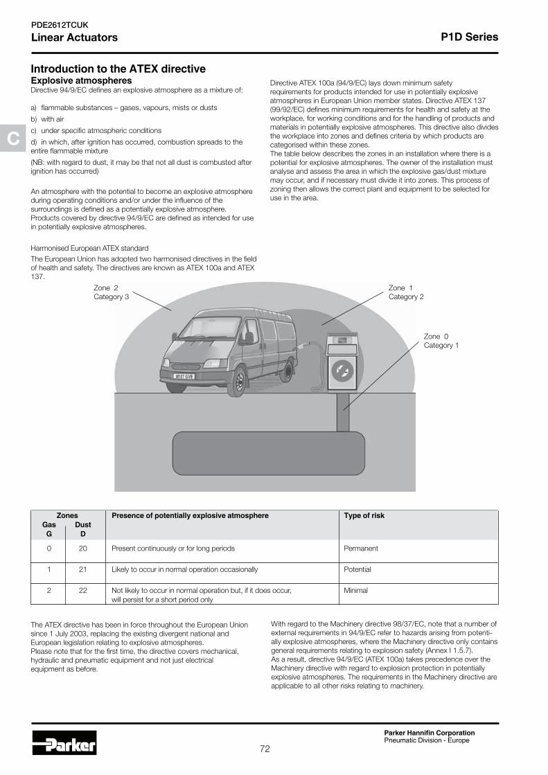
Directive ATEX 100a (94/9/EC) lays down minimum safety requirements for products intended for use in potentially explosive atmospheres in European Union member states. Directive ATEX 137 (99/92/EC) defines minimum requirements for health and safety at the workplace, for working conditions and for the handling of products and materials in potentially explosive atmospheres. This directive also divides the workplace into zones and defines criteria by which products are categorised within these zones. The table below describes the zones in an installation where there is a potential for explosive atmospheres. The owner of the installation must analyse and assess the area in which the explosive gas/dust mixture may occur, and if necessary must divide it into zones. This process of zoning then allows the correct plant and equipment to be selected for use in the area.
The ATEX directive has been in force throughout the European Union since 1 July 2003, replacing the existing divergent national and European legislation relating to explosive atmospheres.Please note that for the first time, the directive covers mechanical, hydraulic and pneumatic equipment and not just electrical equipment as before.
With regard to the Machinery directive 98/37/EC, note that a number of external requirements in 94/9/EC refer to hazards arising from potenti-ally explosive atmospheres, where the Machinery directive only contains general requirements relating to explosion safety (Annex I 1.5.7).As a result, directive 94/9/EC (ATEX 100a) takes precedence over the Machinery directive with regard to explosion protection in potentially explosive atmospheres. The requirements in the Machinery directive are applicable to all other risks relating to machinery.
0 20 Present continuously or for long periods Permanent
1 21 Likely to occur in normal operation occasionally Potential
2 22 Not likely to occur in normal operation but, if it does occur, Minimal will persist for a short period only
Zone 1Category 2
Zone 2Category 3
Zone 0Category 1
C
72Pneumatic Division - Europe
PDE2612TCUK

Levels of protection for the various equipment categories
The various equipment categories must be capable of operating in accordance with the manufacturer’s operating specifications at defined levels of protection.Definition of groups (EN 1127-1)
Very M1 Two independent means of protection or safety, ensuring that The equipment remains energised and high the equipment remains functional even in the event of two faults and functional even with an explosive occurring independently of each other atmosphere present
Very 1 Two independent means of protection or safety, ensuring that The equipment remains energised and high the equipment remains functional even in the event of two faults functional in zones 0, 1, 2 (G) and/or occurring independently of each other zones 20, 21, 22 (D) High M2 Protection suitable for normal operation and severe The equipment is de-energised in the operating conditions event of an explosive atmosphere High 2 Protection suitable for normal operation and frequent faults, or The equipment remains energised and func- equipment in which faults normally have to be taken into account tional in zones 1, 2 (G) and/or zones 21, 22 (D) Normal 3 Protection suitable for normal operation The equipment remains energised and func- tional in zones 2 (G) and/or zones 22 (D)
Temperature classes
Classification of flammable gases and vapours on the basis of ignition temperature
G D G D G D
0 20 1 21 2 22
The product catalogues contain copies of the declaration of conformity demonstrating that the product meets the requirements of directive 94/9/EC.The declaration is only valid in conjunction with the instructions con-tained in the installation manual relating to the safe use of the product throughout its service life. The instructions relating to the conditions in the surrounding area are particularly important, as the certificate is invalidated if the instructions are found not to have been adhered to during operation of the product.If there is any doubt as to the validity of the certificate of conformity, contact Parker Hannifin customer service.
The installation manual of the product contains instructions relating to
T1 Over 450
T2 (300) – 450
T3 (200) – 300
T4 (135) – 200
T5 (100) – 135
T6 (85) - 100
the safe storage, handling, operation and servicing of the product.The manual is available in different languages, and can be downloaded from www.parker.com/euro_pneumatic.This document must be made accessible in a suitable place near where the product is installed. It is used as a reference for all personnel autho-rised to work with the product throughout its service life. We, the manufacturer, reserve the right to modify, extend or improve the installation manual in the interests of the users.
For more information about ATEX see EUs homepage: http://europa.eu.int/comm/enterprise/atex/
Group I Equipment intended for use in underground parts of mines as well as those parts of surface installations of such mines likely to be en-dangered by flammable vapours and/or flammable dusts.Group II Equipment intended for use in other places exposed to explosive atmospheres.G = gas and D = dust
C
73Pneumatic Division - Europe
PDE2612TCUK

All installation, connection, commissioning, servicing and repair work on P1D cylinders must be carried out by qualified personnel taking account of the following
connection diagrams associated with the application.
accident prevention)
P1D cylinders are designed to provide linear movement in industrial applications, and should only be used in accordance with the instruc-tions in the technical specifications in the catalogue, and within the operating range indicated on the rating plate. The cylinders meet the applicable standards and requirements of directive 94/9/EC (ATEX)
The cylinders must not be used underground in mines susceptible to firedamp and/or flammable dusts. The cylinders are intended for use in areas in which explosive atmospheres caused by gases, vapours or mists of flammable liquids, or air/dust mixtures may be expected to oc-cur during normal use (infrequently)
Before using the cylinders in an Ex-area, you should check the following:Do the specifications of the P1D-S cylinder match the Ex-classification of the area of use in accordance with directive 94/9/EC (previously ATEX 100a)
1. When installing the P1D-S cylinder, is it certain that there is no poten-tially explosive atmosphere, oil, acids, gases, vapours or radiation?
2. Is the ambient temperature as specified in the technical data in the catalogue at all times?
3. Is it certain that the P1D-S cylinder is adequately ventilated and that no forbidden additional heat is added?
4. Are all the driven mechanical components ATEX certified?
5. Check that the P1D-S cylinder is safely earthed.
6. Check that the P1D-S cylinder is supplied with compressed air. Ex-plosive gas mixtures must not be used for driving the cylinder.
7. Check that the P1D-S cylinder is not equipped with a metal
scraper ring (special version).
temperature.
cylinder.
through its support, a metallic tube or separate conductor.
Ex-area, but must be connected to the silencer or, preferably, piped and released outside the Ex-area.
than those permitted in accordance with the catalogue
Explosive gas mixtures must not be used
Ex-areas
The P1D cylinder must be kept clean on the outside, and a layer of dust/dirt thicker than 1 mm must never be allowed to form.Strong solvents should not be used for cleaning, because they can cause the seal (material PUR) around the piston rod to swell, potentially increasing the temperature. Inspect and verify that the cylinder, with attachments, compressed air fittings, hoses, tubes, etc. meet the stan-dards of ”safe” installation.
Communauté Européenne = EU CE on the product shows that Parker Hannifin products meet one or more EU directives.
Ex means that this product is intended for use in potentially explosive atmospheres.
II Stands for the equipment group (I = mines and II = other hazardous areas).
Stands for equipment category 2G means the equipment can be used in zones 1 and 2 where there is a risk involving gases, vapours or mists of combustible liquids and 2D in zones 21 and 22 where there is a risk involving dusts. 2GD Means the equipment can be used in zones 1, 2, 21 and 22.
c Safe design (prEN 13463-5)
If equipment is in temperature class T4, the maximum surface temperature must not exceed 135 °C. (To guarantee this, the product has been tested to ensure that the maximum is 130 °C. This provides a safety margin of 5 °K).
Maximum permitted surface temperature on P1D-S cylinder in atmospheres containing potentially explosive dusts.
Supplementary safety instructions for P8S- GPFLX/EX sensors installed
in Ex-areas
C
74Pneumatic Division - Europe
PDE2612TCUK

Serious, even fatal, damage or injury may be caused by the hot moving parts of the P1D cylinders in the presence of explosive gas mixtures and concentrations of dust.
Safety instructions
by trained personnel
detects the magnetic field in potentially explosive areas. The sensor can only be installed in the T-groove of these cylinders.
the following attachments:
Suitable for P1S and P1A diameter 10 - 25 mm
Suitable for P1S diameter 32 - 63 mm
Suitable for P1S diameter 80 - 125 mm
The following data applies to these attachments:
- Ambient temperature Ta = 0 °C to 45 °C
- Low energy absorption to EN 50 021
cylinders by means of this attachment:
Suitable for P1D-T diameter 32 - 125 mm, P1E-T diameter 160 – 200 mm and C41 diameter 160 – 200 mm
General: The sensor must be protected from UV radiation. The cable must be installed such that it is protected from external influences, for example it may be necessary to attach an external strain relief to the cable.
Operating voltage Ub = 18 to 30 V DCMax. load current Ia d” ¡Ü 70 mAAmbient temperature: -20 °C to 45 °C
When connecting the sensor to a power source, please pay attention to the followinga) the load data (operating voltage, continuous load current)b) the wiring diagram for the sensor
Our P8S-GPFLX/EX cylinder sensor is maintenance free, but the cable connections should be checked at regular intervals.The sensor must be protected from UV radiation. The sensor must be kept clean on the outside, and a layer of dirt thicker than 1 mm must never be allowed to form. Strong solvents should not be used for clea-ning as they may damage the sensor.
Communatuté Européenne = EU
CE on the product shows that Parker Hannifin products meet one or more EU directives.
Ex means that this product is intended for use in potentially explosive atmospheres.
II Stands for the equipment group (I = mines and II = other hazardous areas)
Stands for the equipment category 3G means the equipment can be used in zone 2 where there is a risk involving gases, vapours or mists of combustible liquids.
EEx means that this is an electrical product intended for use in Ex-areas.
nA IIn Not ignitable to EN50021, A Explosion group tested with acetone, ethanol, toluene and xylene; II Not for use in the mining industry.
If equipment is in temperature class T4, the maximum surface temperature must not exceed 135 °C. (To guarantee this, the product has been tested to ensure that the maximum is 130 °C. This provides a safety margin of 5 °K.) X Must be installed in accordance with the installation manual.
Stands for equipment category 3D in zone 22 where there is a risk involving dusts.
Maximum permitted surface temperature on the sensor in atmospheres containing potentially explosive dusts.
IP67 Satisfies protection class IP67.
Parker Hannifin guarantees that our cylinder attachments, tube fittings, tubes, etc. are not subject to the provisions of the ATEX directive.
A component means any item essential to the safe functioning of equip-ment and protective systems but with no autonomous function.
Components intended for incorporation into equipment or protective systems which are accompanied by an attestation of conformity with the ATEX directive, including a statement of their characteristics and how they must be incorporated into products, are considered to con-form to the applicable provisions of directive 94/9/EC. Ex-components as defined in the European standard EN 50014 are components in the sense of the ATEX directive 94/9/EC as well. Components must not have the CE marking affixed unless otherwise required by other directives.
leads
C
75Pneumatic Division - Europe
PDE2612TCUK

Cylinder bore AM B BA BG D D4 E EE G KK L2 L8 L9 L12 mm mm mm mm mm mm mm mm mm mm mm mm mm mm
32 22 30 30 16 12 45,0 50,0 G1/8 28,5 M10x1,25 16,0 94 146 6,0 40 24 35 35 16 16 52,0 57,4 G1/4 33,0 M12x1,25 19,0 105 165 6,5 50 32 40 40 16 20 60,7 69,4 G1/4 33,5 M16x1,5 24,0 106 180 8,0 63 32 45 45 16 20 71,5 82,4 G3/8 39,5 M16x1,5 24,0 121 195 8,0 80 40 45 45 17 25 86,7 99,4 G3/8 39,5 M20x1,5 30,0 128 220 10,0100 40 55 55 17 25 106,7 116,0 G1/2 44,5 M20x1,5 32,4 138 240 14,0125 54 60 60 20 32 134,0 139,0 G1/2 51,0 M27x2 45,0 160 290 18,0
Cylinder bore PL PP R RT SS SW TT VA VD WH WL WT mm mm mm mm mm mm mm mm mm mm mm
32 13,0 21,8 32,5 M6 4,0 10 4,5 3,5 4,5 26 21 M8x1 40 14,0 21,9 38,0 M6 8,0 13 5,5 3,5 4,5 30 23 M10x1,25 50 14,0 23,0 46,5 M8 4,0 17 7,5 3,5 5,0 37 31 M14x1,5 63 16,4 27,4 56,5 M8 6,5 17 11,0 3,5 5,0 37 31 M14x1,5 80 16,0 30,5 72,0 M10 0 22 15,0 3,5 4,0 46 39 M18x1,5100 18,0 35,8 89,0 M10 0 22 20,0 3,5 4,0 51 39 M18x1,5125 28,0 40,5 110,0 M12 0 27 17,5 5,5 6,0 65 53 M24x2
S=Stroke
Cylinder bore B BA L8 L
9 R Stroke tolerance Stroke tolerance
mm mm mm mm up to stroke 500 mm for stroke over 500 mm
32 d11 d11 ±0,4 ±2 ±0,5 +0,3/+2,0 +0,3/+3,0 40 d11 d11 ±0,7 ±2 ±0,5 +0,3/+2,0 +0,3/+3,0 50 d11 d11 ±0,7 ±2 ±0,6 +0,3/+2,0 +0,3/+3,0 63 d11 d11 ±0,8 ±2 ±0,7 +0,3/+2,0 +0,3/+3,0 80 d11 d11 ±0,8 ±3 ±0,7 +0,3/+2,0 +0,3/+3,0100 d11 d11 ±1,0 ±3 ±0,7 +0,3/+2,0 +0,3/+3,0125 d11 d11 ±1,0 ±3 ±1,1 +0,3/+2,0 +0,3/+3,0
AM
ØB
ØD
KK
WT
BG
VD
G
WH
WH
WH
WL
WH + S
L2
L12
ØD
4
PP
PL
SS
TT Ø
BA
VA
G
L8 + S
RT
R
E
L9 + 2 x S
DIN 439B
SW
EE
CAD drawings on the Internet
Our home page www.parker.com/euro_pneumatic includes the AirCad Drawing Library with 2D and 3D drawings for the main versions.
C
76Pneumatic Division - Europe
PDE2612TCUK

AM
ØB
ØD
KK
VD
G
3
49 18
3
WH
L2
L12
PP
E2 maxPL
SS
TT Ø
BA
VA
GL8 + S
RT
R
E
E1
DIN 439B
SW
EE
ØD
7
AM
ØB
ØD
KK
VD
G
WH
L2
L12
ØD
7
PP
PL
SS
TT Ø
BA
VA
G
L8 + S
RT
R
E
E3
DIN 439B
SW
EE
AM
ØB
ØD
KK
VD
G
WH
L2
L12
ØD
5
ØD
6
PP
PL
SS
TT Ø
BA
VA
G
L8 + S
RT
R
E
DIN 439B
SW
EE
Cylinder bore Elbow fittings, tubing Ømm Straight fittings, tubing Ømm 4 6 8 10 4 6 8 10 D5 D6 D7 E1 E2max E3 E3 E3 E3 E3 E3 E3 E3 mm mm mm mm mm mm mm mm mm mm mm mm mm mm
32 36 5,3 49,6 32 30,0 42 44 - - 38 40 - - 40 44 5,3 57,3 36 34,7 46 48 - - 42 44 - - 50 55 7,1 69,3 42 40,7 - - 56 76 - - 48 50 63 68 7,1 82,3 49 46,2 - - 64 83 - - 55 75 80 86 8,9 99,3 57 54,7 - - - - - - - -100 106 8,9 117,6 68 64,0 - - - - - - - -125 132 10,8 142,8 81 75,5 - - - - - - - -
Other dimensions, see opposite page
P1D Flexible Porting Ø80 - Ø125 can be ordered with threaded ports only or with factory-fitted elbow or straight push-in fittings (see position 20 in the order code key.)
Minimum stroke for P1D Clean is 25 mm with 0-2 sensors and 100 mm with 3-4 sensors.
C
77Pneumatic Division - Europe
PDE2612TCUK
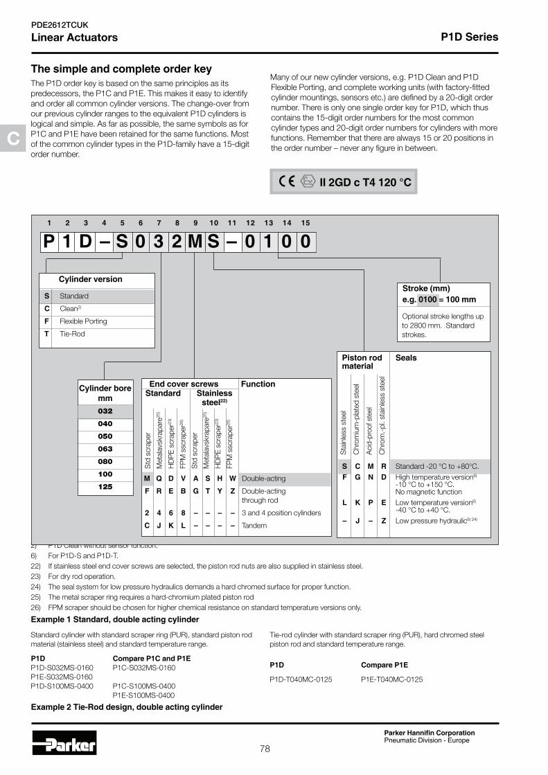
The P1D order key is based on the same principles as its predecessors, the P1C and P1E. This makes it easy to identify and order all common cylinder versions. The change-over from our previous cylinder ranges to the equivalent P1D cylinders is logical and simple. As far as possible, the same symbols as for P1C and P1E have been retained for the same functions. Most of the common cylinder types in the P1D-family have a 15-digit order number.
Many of our new cylinder versions, e.g. P1D Clean and P1D Flexible Porting, and complete working units (with factory-fitted cylinder mountings, sensors etc.) are defined by a 20-digit order number. There is only one single order key for P1D, which thus contains the 15-digit order numbers for the most common cylinder types and 20-digit order numbers for cylinders with more functions. Remember that there are always 15 or 20 positions in the order number – never any figure in between.
Standard cylinder with standard scraper ring (PUR), standard piston rod material (stainless steel) and standard temperature range.
P1D-S032MS-0160 P1C-S032MS-0160 P1E-S032MS-0160 P1D-S100MS-0400 P1C-S100MS-0400 P1E-S100MS-0400
Tie-rod cylinder with standard scraper ring (PUR), hard chromed steel piston rod and standard temperature range.
P1D-T040MC-0125 P1E-T040MC-0125
2) P1D Clean without sensor function.
6) For P1D-S and P1D-T.
22) If stainless steel end cover screws are selected, the piston rod nuts are also supplied in stainless steel.
23) For dry rod operation.
24) The seal system for low pressure hydraulics demands a hard chromed surface for proper function.
25) The metal scraper ring requires a hard-chromium plated piston rod
26) FPM scraper should be chosen for higher chemical resistance on standard temperature versions only.
032
040
050
063
080
100
125
Optional stroke lengths up to 2800 mm. Standard strokes.
Standard -20 °C to +80°C.
High temperature version6)
-10 °C to +150 °C. No magnetic function
L K P E Low temperature version6)
-40 °C to +40 °C.
Low pressure hydraulic6) 24)
Sta
inle
ss s
teel
Chr
om
ium
-pla
ted
ste
el
Aci
d-p
roof
ste
el
Chr
om
.-p
l. st
ainl
ess
stee
l
S Standard
Clean2)
F Flexible Porting
Tie-Rod
Std
scr
aper
Met
alav
skra
par
e25)
HD
PE
scr
aper
23)
FPM
ssc
rap
er26)
Std
scr
aper
Met
alav
skra
par
e25)
HD
PE
scr
aper
23)
FPM
ssc
rap
er26)
Double-acting
Double-acting through rod
2 4 6 8 – – – – 3 and 4 position cylinders
Tandem
C
78Pneumatic Division - Europe
PDE2612TCUK

mm mm
25 Conn. G1/8 40 50 80 100 125 160 200 250 320 400 500
40 25 Conn. G1/4 40 50 80 100 125 160 200 250 320 400 500
50 25 Conn. G1/4 40 50 80 100 125 160 200 250 320 400 500
25 Conn. G3/8 40 50 80 100 125 160 200 250 320 400 500
Cyl. bore Stroke Order code mm mm
80 25 Conn. G3/8 40 50 80 100 125 160 200 250 320 400 500
100 25 Conn. G1/2 40 50 80 100 125 160 200 250 320 400 500
125 25 Conn. G1/2 40 50 80 100 125 160 200 250 320 400 500
The cylinders are supplied complete with one zinc plated steel piston rod nut.
The order numbers on this page refer to P1D Standard without sensors. The cylinders can be ordered with sensors, fittings, piston rod and cylinder mountings, speed controls etc. for efficient logistics. Please refer to the order key to select cylinders with factory-fitted accessories.
C
79Pneumatic Division - Europe
PDE2612TCUK