PD-NCB Consultants Limited - British Columbia Consultants Limited r~- In association with Wright...
189
PD-NCB Consultants Limited r~- In association with Wright Engineers Ltd & Golder Associates Report No. 2 Preliminary Report on Hat Creek Openpit No.1 Volume I British Columbia Hydra and Power Authority London March 1976
Transcript of PD-NCB Consultants Limited - British Columbia Consultants Limited r~- In association with Wright...

PD-NCB Consultants Limited
r~- In association with
Wright Engineers Ltd & Golder Associates
Report No. 2
Preliminary Report on Hat Creek Openpit No.1
Volume I
British Columbia Hydra and Power Authority
London March 1976

CONTENTS L.
r-
. .
v-.
L
L
I
r
.
I
.
CHAPTER I - INTRODUCTION
Terms of Reference _.. Progress to Date .,. Basic Da?a ._. _;_
CHAPTER II - GEOLOGICAL AND GEGTECHNICAL --- ASSESSMENT
Innroduction _,_ ., S,tructure ",I .~" ,
Faulting Folding .I: ::: 1
Materials -, ..~ " Overburden .I_ Coal ..~ ,..
Geotechnical Implications the Geology ,.. ".I ,
Geotechnical ~ ~. I_~ I
CHAPTER III - MINE PLANNING
General .,. ;. . . . ,
Type
Structure Coal Quality 1:: 1: Coa,l Production ., Physical and Chemical
Properties . . . _" Groundwater .~ of Mine
of
. . ^
‘ .
I / .
r .
~ . i
, . .
I ,
_ . .
I I .
I .
.
. ~ .
I _ .
. .
. . r
~ 1
I I .
Factors Controlling the Design of a Surface Mine
Pit Slopes . . Main Incline . . Depth Limitation Pit Design .
Development Programme Environmental Aspects . . .
CHAPTER IV - MTNING OPERATIONS --
Introduction ,, _ Development ~;~ ELI . DiversIon of Hat Creek . Superficials .". .;, L Pit Wasie ,i. ..I _ Coal and Segregated Wasre Minimum Face Length
PoIential tar Increasing Mine Out.put I.I ~ ~. .
Blasting ,,~ .,. ..~ ~.. Transport ~.. . . . nil . Mud Flows Drainage and Pumping ii, . Mobile Mining Equipment _ ~_ _ Equipment Costs ,. _.. . ~ .
. . .
. ”
0 . .
. r I
. ~ .
~ . .
. ~ .
. . ~
1 . .
. I
. . I
. I .
.
. .
. .
. . .
. .
*
, . ~
. ,
. ~ .
0 I .
_ )
. 0
~ . I
~ _ .
. ~ .
” ~ I
~ . ~
;
_ ~
.
EE
1 1 2
6 7
9 9 9 9
10 10 10
11 13 13 14 15 17 17
18 18 18 19 19 20 20
21 21 22 23 23 24
* , * 25
CHAPTER Iv (continued) Coal Removal ,..
Transport Out of'Pit" 1:: : Transport by Pneumatic
Pipeline ;., . . . . Transport by Dump Truck . Transport by Conveyor
Belt . . . . . . _I, In-Pit Transfer Stations o Main In-Pit Incline Conveyors
Spontaneous Combustion and Fire Prevention ".. IIi _,~ .., .
. .
.
.
.
CHAKTERV - SURFACE PLANT AND COAL PREPARATION
Introduction ,.‘ __ .." .1 I Stockpiling and Recovery . . . Coal Preparation ~.. ,.. ..I Coal Quality _. ._" . . . I.I
Methods of Assigning Values to Blocks
Quality Control'Methods : 1: Mine Power Supply ~_~ ~.. I." Schedule of Fixed Installations
CHAPTER VI - WASTE AND ASH DISPOSAL
Materials and Quantity .~. .I. Dumps ._. 1.. . . . . . . . . . Disposal Areas ..~ . . . :..
600-ft Pit ..~ l__ .,, 1,500-ft Pit .;. _I. . . .
Methods of Waste Transport jj.
CHAPTER VII - INFRASTRUCTURE AND CIVIL WORKS
Hat Creek Diversion . . . Object j . ,,. . . . Data .‘. Diversion Alternatives Hydrology .. .., Diversion Scheme .._
Surface Drainage . ,~. Road Diversion . . . ~,. Surface Mine Buildings ,.. Road Construction and Road
Improvement ..I . . . .~ ~ Services ,_~ ,,_~ .." ,., Housing ,.. ._. __" ~.. Schedule of Infrastructure
CHAPTER VIII - ECONOMICS -
Basis Basic Financial Data Explanation of Tables
Capital Costs . . .
. . .
. . .
I . .
. . .
.
. . .
I . ^
.
. . .
. . .
,
~ . .
. ~ ~
. . .
. 1 .
~ < .
I _ .
. . ,
. . .
. .
* . .
. . .
. .
, . .
. . .
. . .
. . .
. .
.
~ n .
I I
~ .
. . .
. .
. ~
~
. n .
. . .
,
I . .
I * .
~ . .
. 1 0
~ I 1
I .
.
. _ .
1 . . 25
I . * 25
. . . 25
. . . 26
. . , 26
. , . 26 1 . I 27
. . . 27
. 29 n . . 29 . . . 30
. . 30
* . . 31 . . 32
. . . 32
. . . 33
. . . 34
. . . 34 35
. . I 35
. . . 36 1 I . 37
. . 38
. . . 38
. . ~ 38
. . . 38
. 38
. . . 39
. . . 39 . . 39
. . . 40
. ~ . 40
. I 41 ~ 41 . * . 41
. 42 . 42
I . 43 . . 43
_ iii -
CHAPTER VIII (continued) Direct: Operating Costs -__ ,,:
Total Investment and Capital Charges lo_ I~. ~~j
Production Cost (1975 Prices) - 600-ft Pit .~, I~_ ~,.
Production Cost (1975 Prices) - 1,500-ft Pit
Discounted Cash Floi'(1975~ Prices)...
Confidence Limits of-Estimate&" Selling Price ~._ ~^_ 1~~
Life of Openpit No 1 ~,~ Production Cost (Inflated) Discounted Cash Flow
(Inflated) ~_. Lag Opportunity Value of Rat Creek
Coal .__ __" ~., .,, ~.j Break-Even Stripping Ratio .
CHAPTER IX - SUMMARY AND RECOMMENDATIONS
General _~. . .., ,.. ~( ~ln Data Collection . ..~ ~~ r
Geological and Geotechnical Programmes .I1 I., .ji .jj
Coal Quality ~.I .,, ~. ".. Pit Optimisation _.. ,.~ .L. Coal Testing . . . .", 1,1 ,~.
Labour i.~ . 1 I~_ ~_; 1~~ Budgets . . . ~I. .;, ~II ~I_ ,.. Environmental Considerations _II I,"
43
44
44
45
45
46 46 47
47
47 48
50 50
51 51 51 51 52 52 52
- -

Appendix "A"
Appendix "B"
Appendix "C!"
Appendix "D"
Appendix "E"
- iv -
LIST OF APPENDICES
Report No 1 - Interim Report and Geotechnical Exploration
7
on Geological at Hat Creek 1
List of Documents and Drawings received by PD-NCB from 19th November, 1975 to 23rd February, 1976
Underground Mining
Basic Financial Data
Labour Requirements
- v -
LIST OF TABLES
I
I
r
.
F..
Table I
Table II
Table III
Table IV
Table V
Table VI
Table VII
Table VIII
Table IX
Table X
Table XI
Table XII
Table XIII
Table XIV
Table XV
Table XVI
Table XVII
Table XVIII
Table XIX
Table XX
Table XXI
Table XXII
Table XXIII
Table XXIV
Table XXV
Basic Planning Data
Openpit No 1 Volumes, Tonnages and Ratios
Production Schedule - Yearly and Cumulative
Mobile Mining Equipment Requirements
Schedule of Mobile Mining Equipment - Initial and Replacement Costs
Schedule of Typical Equipment
Mobile Mining Equipment - Cost Allocation
Electric Power - Consumption and Costs
Summary of Electrical Energy Costs
Schedule of Equipment - Fixed Installations and Capital Cost
Mine Waste and Power Station Ash Disposal
Dumping Space Available at 100-ft Intervals
Hat Creek Diversion Costs
Hat Creek Surface Drainage Costs
Hat Creek Road Re-location Costs
Surface Mine Buildings and Housing Costs
Cost Schedule of Equipment - Infrastructure
Labour Schedule and Payroll Costs
Managerial, Technical and Administrative Staff - Numbers and Salary Costs
Material and Fuel Cost Summary (1975 Prices)
Direct Operating Cost Summary
Deprecia~tion Summary
Capital Investment, Interest during Construction, Interest and Insurance (1975 Prices)
Rom Coal Production Cost
Cash Flow (Expenses) and Uniform Selling Price (1975 Prices)

‘-7
- vi -
7 Table XXVI - Coal Production Cost (Inflated) J
Table XXVII - Cash Flow (Expenses) and Uniform Selling Price 7 (Inflated)
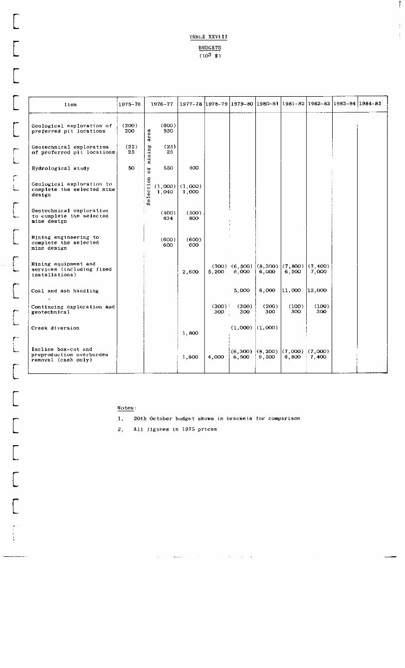
Table XXVIII - Budgets
. .
..4

- vii -
LIST OF PLATES
Plate 1 - Section 19,000 E
Plate 2 - Secticn 19,500 E
Plate 3 - Section 20,000 E
Plate 4 - Section 20,500 E
Plate 5 - Section 77,000 N
Plate 6 - Section 78,000 N
Plate 7 - Section 79,000 N
Plate 8 - Section 80,000 N
Plate 9 - Section 80,500 N
Plate 10 - Section 811500 N
Plate 11 - Isopachytes of Superficial Deposits
Plate 12 - Contours at Ease of Superficial Deposits
Plate 13 - Isopachytes of Total Overburden
Plate 14 - Contours at Top of Coal
Plate 15 - Legend of Symbols used on Geological Plans and Sections
Plate 16 - Location of Mudslides, Creek Diversion and Road Re-Routing
Plate 17 - Stages of Pit Development to 1,500-ft Elevation (Surface Intercepts)
Plate 18 - Proposed Bench Arrangement using 150-ton Trucks and Working Bench Overall Slope
Plate 19 - Main Incline Conveyor and Haul Road Arrangement
Plate 20 - Cumulative Volumes of Waste versus Cumulative Tonnage of In situ Coal
Plate 21 - Coal Requirements for a 3 x 750-MW Power Station - Yearly Waste Removal - Yearly Stripping Ratio
Plate 22 - Cumulative Coal Requirements for a 3 x 750-MW Power Station and Cumulative Waste Removal
Plate 23 - Construction Schedules

Plate 24 -
Plate 25 -
Plate 26 -
Plate 27 -
Plate 28 -
Plate 29 -
Plate 30 -
Plate 31 -
Plate 32 -
Plate 33 -
Plate 34 -
Plate 35 -
Plate 36 -
Plate 37 -
Plate 38 -
Plate 39 -
Plate 40 -
Plate 41 -
Plate 42 -
Plate 43 -
Plate 44 -
Plate 45 -
Plate 46 -
Mean Haulage Distances
Total Drilling Hours
Total Shovel Hours
Total Truck HOURS
Machinery Requirements
Schematic In-Pit Breaker Feeder Transfer Station
Schematic Line Diagram of Proposed Stockpiling Arrangement
Proposed Conveyor - Stockpile and Waste Dump Layout
Conceptual HT Power Distribution - Ultimate Pit
Plan of Superficials, Pit Waste and Ash Disposal Areas - 600-ft Pit
Plan of Superficials, Pit Waste and Ash Disposal Areas - 1,500-ft Pit
Schematic Line Diagram of Proposed Waste Disposal Scheme
Shops and Warehouse
Change House
Administration Building
Core Shed
Senior Staff Camp
Work Force Camp
Corporate Overhead Rates
Variation of Production Cost with Instantaneous Stripping Ratio
Production Cost and Uniform Selling Price (Uninflated, 1975 prices)
Opportunity Values for Coal and Lignite
Variation of Break-even Stripping Ratio with Production Cost at Various Selling Prices
. .
.
_I
(contained in Volume II)

CHAPTER I
INTRODUCTION
_
r,-
1. This report deals with a conceptual mine, "Openpit No l", situated in Area 1 at the northernend bf the Hat Creek valley. The extraction of the pit is considered in two phases; down to the '2,400-ft level, called the 600-ft pit and, sub- sequently, down to the 1,500-ft level, called the 1,500-ft pit.
TERMS OF REFERENCE
2. Report No 1 dated November 1975, "Interim Report on Geological and Geotechnical Exploration at Hat Creek" (Appendix "A") included the full terms of reference for the study but was confined to items 3(a) and 3(b).
3. The main conclusions of Report No 1 were:-
(i) Geological exploration should concentrate on the northern end of Area 2 to bring it up to the same level as Area 1. Area 1 looks the most promising at this stage.
(ii) The depth of geological exploration and geotechnical investigation should be limited to a tentative pit depth of 600 ft, with the exception of an occasional deeper hole to explore major features.
(iii) Geotechnical problems will be severe due to surface mud ~flows and the nature of the rocks in the mine, particularly the mudstones.
(iv) Coal quality data require to be processed in blocks so as to be able to select a mining sequence and to develop production schedules.
PROGRESS TO DATE
4. A series of meetings took place in Vancouver in December 1975 and it was decided to continue geological drilling at the northern end of Area 2 (as recommended in (i) above).
5. This means, of course, that no additional geological information has been received on Area 1 since the preparation of Report No 1. Also, very little additional geotechnical data will be available.
6. Chapter II summarises the geological and geotechnical position to date but basically it is unchanged since Report No 1 was prepared.

-2-
7. A visit was made with British Columbia Hydro and Power Authority (BCH) personnel to Centralia Mine, Washington, USA, to examine pit conditions etc in a geological setting which has similarities to 1Ia.t Creek. The difficulties caused by the mudstones in the mine and in the washery were very evident. This mine is now successfully using a bucket wheel excavator and conveyor system in the superficial deposits, having failed disastrously in the deeper, harder rocks.
8. The documentary information received since 19th November, 1975 is listed in Appendix "B".
BASIC DATA
9. Table I lists the basic data used in this Report. Some of the data have been provided by Dolmage Campbell and Associates (WA) but the remainder is assumed. Quite clearly these assumptions will need verification as soon as it is possible to do so.

-3-
CHAPTER II
GEOLOGICAL AND GEOTECHNICAL ASSESSMENT
INTRODUCTION
1. Since Report No 1 was prepared, the borehole logs for Area 1 have been re-examined in order to check the inter- pretative cross-sections of DCA and BCH prior to preparing additional sections and plans for conceptual-mine-design purposes. No further drilling information has been available for this study but the location and inclination of the more recent boreholes have been checked and, accordingly, some data have been re-plotted- The latest geophysical inter- pretations have been examined but have little relevance to the current phase of the work.
2. The structural interpretation upon which the present mine-planning study has been based is shown on Plates 1 to 14 and a legend of the symbols and abbreviations used appears on Plate 15. These plans and sections are based on topographical maps compiled to an approximate scale of 1 in to 2,000 ft by McEllanney Surveying and Engineering Ltd from an aerial survey dated 13th May, 1975, Additional interpretative data were also supplied by DCA and BCH.
3. No new information has been forthcoming on the composition of either coal, overburden or parting materials in this area, although boreholes in Area 2 may have some bearing on the geology of the South-eastern side of the mine. No additional information relating to the groundwater of Area 1 has been received,
STRUCTURE
Faulting
4. Four main faults traverse the northern section of Area 1, apparently converging towards the north. Some of these faults may continue well to the south of Area 1, not- withstanding a possible element of E-IV cross-faulting. The northern faults from east to west are as follows:-
(i) Mag Fault - a normal the east
fault down-throwing to and trending NW-SE
(ii) Fault "H" - a normal the west
fault down-throwing to and trending NhW-SSE
(iii) Fault "S" - a normal the east
fault down-throwing to and trending N-S
(iv) Dry Lake Fault - a normal fault down-throwing to the east and trending NE-SW

-4-
Two faults which occur towards the south of Area 1 are:-
(v) Trig Fault - a normal fault with steep hade down-throwing to the south-east and trending NE-SW
(vi) Finney Fault - assumed to be a normal fault, down-throwing to the south and trending ENE-WSW
If the throw directions on the Trig and Mag faults are correct, there is also the possibility of a further, more easterly fault down-throwing to the west. However, the plan and section data on the magnitude and direction of the Mag, Trig, Finney and Dry Lake faults are uncertain.
5. The effect of the northerly faulting is to form a graben, or trough, along the valley to which the coal is confined but within which the Mag fault and "H" fault produce an ancillary horst. The major coal-bearing area lies between the Mag fault and fault "S". Owing to the shortcomings of the strata correlation there is still no precise information on the throw of the faults but, using the roof and, in places, the floor of the thickest coal units as indicators, there appear to be some marked changes in throw along the faults.
6. The fault positions are shown on the plans of total overburden isopachs and top of coal contours. At the northern end of Area 1 these faults converge north of the small outcrop areas near Hat Creek, coal-bearing strata being apparently absent north of this point. To the south of Area 1, the geology is highly conjectural, The Finney fault has been assumed to have the attitude shown on Plate 1 (as in DCA Report). On this basis, near-surface coal would be absent to the south. Its position is, however, uncertain as is also the direction of its displacement. The location of this fault has a significant effect on the coal reserves and the economic pit limit. Two boreholes south of this fault position show both thinner and thicker coal units, similar to those occurring further north. This could indicate that there is either:-
(i) A reversal in direction of throw along Finney fault, with a northerly down-throw in the west and a southerly down-throw in the east or
(ii) the Finney fault trends parallel to the Dry Lake fault and lies further south in the SW corner of Area 1. In this case, changes in strata orienta- tion would also be indicated.
7. In view of the absence of sound correlation of the coal and large gaps in the drilling hereabouts, no assessment has been made of coal south of the conjectural fault position, in either the 6OO-ft or 1,500-ft pits, Clearly more explora- tion is required in this area.

-5-
Folding
a. The strata between the faults is inclined almost everywhere.
(i) The structure of the eastern horst is unknown but current drilling will more closely define the extent of the coal.
(ii) In the southern half of the larger fault block west of the horst (ie between faults "H" and "S"), there is a gentle syncline with its axis running north-south and plunging towards the south. Dips on the flanks are up to 30°, with drill core evidence showing localised dips in excess of this value, Some boreholes also show marked variations in strata dip from top to bottom. The coal in this area exceeds 1,000 ft in thickness and there is as yet no clear evidence of fault-induced thickening by repetition. Whilst some of these dips may reflect the presence of non-diastrophic structures, such as slumping and channel formation, the possible occurrence of numerous small faults with throws of less than 50 ft cannot be eliminated. In that case, slices of strata between these faults would be inclined at a variety of angles. The cause(s) of dip inflexions in individual boreholes requires further investigation. The central section of this area has coal incropping beneath superficial deposits. To the north-east of this fault block there is some evidence of down-warping to the west near fault "S".
(iii) The western flank of the mine comprises a coal bed 400 to 500-ft thick, outcropping to the west and dipping in an ESE direction at 30 to 45'. This coal is somewhat thinner and could represent the lowest stratigraphic horizon of the main deposit against which it abuts along fault "S", the upper coals deteriorating rapidly to the west+
9. The east-west sections, Plates 5 to 10, illustrate the above structures, including the disposition of faults and possible folding within the blocks. Clearly a considerable area of conjecture is present owing to the large gaps in the drilling and projections on to section lines. The north-south section similarly shows the interpretation of the overall structure as plunging towards the south with increasing over- burden cover,
10. Folding and inclination of strata is indicated on the plan of top of coal contours. It now seems quite likely that the coal in Area 1 is all part of a single sequence of deposition with a quite continuous lower bed and a thick central section in the centre of the syncline or basin. Plate 7 shows this quite clearly.

MATERIALS
Overburden
11. This has been conventionally divided into super- ficial materials and waste, the consolidated and/or conformable strata above the coal. The superficial materials are typically drift deposits, ie glacial moraines and till debris and alluvium; Much of this material has been subject to peri- glacial or recent disturbance and large mudslides (see Plate 16) derived from both till and in-situ strata are prominent along the valley. The eastern side of Hat Creek in Area 1 apparently has fairly thick granular deposits, glacial outwash and alluvial gravels. The several types of engineering soils present in the superficial deposits have not been separately identified on the sections. In general, the superficial deposits are thicker on the western and southern flanks of the coal area than along the central and northern valley. Plans showing isopachytes of superficial deposits a:‘i contours of the base of superficial deposits are given on Plates 11 and 12. No marked channels or significant local thickenings are present.
12. The Consultants' current observations on the clay- stones do not differ from those made ea~rlier in the Report No 1. As can be seen from the plans and section, the thickness of overlying claystones increases appreciably to the south. Near the surface, volcanic material has been found in recent drilling in Area 2 so it is possible that such materials, whichmayinclude bentonitic ashes, are present but undetected in Area 1, The isopachytes of total overburden are shown on Plate 1~3 and differ from the isopac~hytes of superficials outside the coal incrop areas.
13 ~ No significant correlations have been made other than between occasional adjacent boreholes. Some of the partings can be projected locally but undetected structures or lateral sedimentary variationsmay be present, which may limit the continuity of these features. No detailed attempt has been made in the sections or plans to show quality variations in the coal. However, in general, the quality (notably ash content) deteriorates from the bottom upwards, from north to south and in the upper section of the thicker coal to both east and west. The coal incrop and outcrop areas and top of coal contours are shown on Piate 14
GEOTECHNICAL IMPLICATIONS OF THE GEOLOGY
14. The implications regarding geological structure and materials remtiin very much as included in the earlier report. In summary, these findings were:-
(.i) There is a moderate balance between upper and lower coals within a 600-ft pits
-7-
r
(ii)
(iii)
(iv)
(v)
15.
The thickness of partings and the frequency of dips in excess of 30° are such that the segrega- tion of waste during excavation will present problems-
A variety of potential failure modes is possible owing to the apparently low shear strength of some of the superficial deposits, as well as the clay- stones and the geometric configurations of structure and pit slope,
Large gaps were present, both within and beyond the immediate coal areas, which require detailed prospecting.
It is not yet possible to fully assess the digga- bility of overburden nor the behaviour of the several rock and soil types regarding site trafficability.
The geological interpretations since the first report have enabled the potential coal area to be extended. This in turn has been increased by the area covered by the 15 to 16' slopes (see Chapter III) and it is suggested that an additional 13,000 ft of drilling should be considered to explore this extension. Much of this additional drilling will be of geotechnieal concern and related to slope stability, diggability, etc, although close attention should be given to a possible extension of the coal area to the south-west corner of the proposed mine.
16. Much additional drilling will be required, both to depth within the coal areas and at the perimeter of the mine, if it is decided to excavate the mine to 1,500-ft depth. The tens of thousands of feet of drilling required for that development can of course be undertaken over many years~ duration, assuming it is possible to organise the waste dumps and lagoons from the 600-ft pit, so that they do not sterilise this potential extension.
GEOTECHNICAL
17. As a result of geotechnical studies carried out by Golder Associates Ltd (GA) in 1975, the following con- clusions were presented in Report No l:-
(i) There is no strong preference for mining Areas 1 or 2 on the basis of geotechnical considerations.
(ii) The nature of the coal deposit and the surrounding rock mass, together with anticipated difficulties in achieving effective drainage, leads to the recommendation that 25O be regarded as the maximum overall slope angle, to be used in preliminary mine planning and that a minimum of 15O may emerge from more detailed studies~

-8-
(iii)
(iv)
(v)
18.
Since it is considered unlikely that economic recovery of this coal depos~it could be achieved without inducing some slope failures, it is recommended that the layout of the pit and access ramp be designed to acc~ommodate such slides, The development of both Areas 1 and 2 should also be considered as a possible means of achieving a secure supply in the event of the disruption of production as a result of slope failure in one pit.
The presence of significant areas of potential mudslide material, in both Areas 1 and 2, must be taken into account in designing the upper slopes of the pit and also in considering the problems of waste disposal, site road design and plant locations.
Because of the unusual severity of the geotechnical and groundwater problems which are likely to be encountered in mining the Hat Creek coal deposit, it is recommended that provision be made for a detailed study of these problems during the design stages and for on-going geotechnical work during the mining operation.
It should be emphasised that the geotechnical . . .-. . . . problems nfgnligntea aaove are not an insurmountable barrier to the effective exploitation of the Hat Creek deposit; Experience in similarly difficult mining sites has shown that an early recognition of slope stability problems and the evolution of a mine design which makes provision for these problems, can lead to an economically acceptable mining operation.
19. In view of the fact that a relatively comprehensive set of conclusions could be drawn on the basis of the geo- technical studies completed in November 1975, only a very limited amount of additional work has been carried out since that time. None of the conclusions presented in Report No 1 has been modified as a result of this work.
20. It should also be emphasised that the geotechnical investigations must relate closely to the findings and on- going investigations of the mine geology.
- 9 -
CHAPTER III
MINE PLANNING
_
r
7~.
r
.
r
GENERAL
1. Valid mine planning clearly depends upon the validity of the geological and geotechnical data, particularly as regards the following:-
(i) Structure
(ii) Quality of the economic mineral
(iii) Physical and chemical properties of all the rocks encountered in and around the mine
(iv) Groundwater quantities and pressures
Structure
2. Although considerable~ information is available concerning the main structural features of the Area 1 deposit (see Plates 1 to14), the stratigraphy of the coal itself is not yet determined, particularly the position, continuity and orientation of the intercalated sterile material, The recommended in-fill drilling programme should provide infor- mation on this but in the meantime, the coal can only be regarded as a mass, utilising DCA's assessment of the inter- calated waste. The mass of coal and intercalates is referred to as in-situ coal. Within its only some of the main structural planes of weakness, which have a marked influence on slope stability, have been located to date. More localised discontinuities still remain to be determined and their influence on stability, et@, assessed. This will be a major feature of the recommended geological and geotechnical exploration programme.
Coal Quality
3. Coal quality aspects are dealt with in Chapter V. In brief, some coal-quality data have been obtained under the DCA programme and an overall average quality calculated. It now remains to process these data in terms of mining blocks (see Chapter 1; para 3 (iv)). This information is not available for this study and, in any case, it should properly form the basis of a much more sophisticated study involving pit optimisation.
Coal Production
4. The power station coal consumption is based on a calorific value of 6,000 Btu/lb and ash content of 28% (Ref DCA's Report, January, 19753, The in-situ coal is estimated by DCA to contain 225% waste and they have assumed that all

- 10 -
this waste can be mined separately in the pit. However, until more is known about the disposition of the waste in the coal it is considered necessary to allow for some dilution of the coal and it has been assumed that only 15% out of the 22% could be removed, leaving 7% dilution. The moisture content of the coal is not known accurately but 20% is assumed in each case (Ref DCA). The rom coal quality would then be approximately 5,500 Btu/lb and 32% ash. The possibility of up-grading the coal by coal preparation is discussed in Chapter V.
5. In terms of coal production quantities, adjustment in the tonnages has been made for this reduced quality as follows:-
Power station fuel
Rom coal
In-situ coal
Annual Calorific Ash including Production Value Waste
tons Btu/lb %
12,000,000 6,000 28
13,100,000 5,500 32
15,400,000 4,670 39
Physical and Chemical Properties
6. Apart from the chemical characteristics of the coal (proximate, ultimate and ash analyses) and a small number of tests on the rocks overlying the coal (by Klohn Leonoff Consultants Ltd), very little information is available. The mechanical properties of all the rocks are clearly needed for slope design, diggability, etc. Thesedata will be obtained during the geotechnical exploration programme which has been recommended.
Groundwater
7. Little is known about the presence and effect of groundwater in the valley and a hydrological study has been recommended (see Report No 1).
TYPE OF MINE
8. At the conceptual stage, it is necessary to consider all feasible mining methods, both surface and underground. The Area 1 deposit is an obvious candidate for surface mining but, owing to the great depth and narrow width of the deposit, it is conceivable that underground mining might, at some stage, become more economic. Therefore, a preliminary study has been made of possible underground mining methods and this is appended (Appendix "C").

- 11 -
r,
.
9. It is evident that a very cheap underground mining system would have to be adopted because of the low value of the mineral. The cheapest method of mining a massive deposit is, of course, block caving but sub-level caving seems more practical. The main drawbacks of underground mining are clearly as follows:-
(i) possibility of gas emission
(ii) tendency ,to spontaneous combustion
(iii) weak rocks, hence major support problems
(iv) presence of slaking mudstones
(VI unknown effects of groundwater
(vi) dilution by mudstones which could not be separated during mining
(vii) reduced quality and increased quantity of rom production due to (vi).
Until these problems are elucidated, underground mining cannot be accepted as feasible. The configuration of the deposit and the nature of the coal would also seem to rule out underground hydraulic mining, insofar as the technology has been developed to date,
10. The economics of underground mining, irrespective of method, also appear very unfavourable, both as regards capital and production costs. It seems unlikely that the capital cost would be less than $300 million ($20 per annual ton of capacity) and the production cost less than $10 per ton. The remainder of this report therefore deals with a conceptual surface mine.
Factors Controlling the Design of a Surface Mine
11. Report No 1 discusses the geotechnical factors which appear to control the design of a surface mine and these are summarised below:-
(i) Slope stability problems will be severe - overall slope angle limited to 25O or less,
(ii) Occasional slides are likely to occur whatever slope angles are adopted and so the mine must be designed to accommodate these slides without loss of production.
(iii) All access ramps must be subjected to stability investigation.
(iv) Superficial mudslides must be guarded against as regards the mine itself.

'- 12 -
(v) n lhe waste mudstone and slide material must be disposed of in safe areas and waste dump stability must be ensured,
(vi) Provision must be made to deal with groundmater, particularly as regards its effect on slope stability.
(vii) A considerable amount of in-pit waste is present as partings in the coal and around the periphery.
12. Certain conclusions have been drawn from considera- tion of these control factors. these being as follows:-
(i)
(ii)
(iii)
(iv)
(v)
(vi)
(vii)
(viii)
(ix)
The shape of the deposit and the instability of the waste mudstones preclude back-filling in the mine whilst mining operations are in progress,
The shape of the deposit and the inherent instability of the slopes favour a roughly circular pit with low slope angles. A concave face is fundamentally more stable than a straight or convex facet “Noses” or buttresses are to be avoided at all costs-
Rapid advance in dep~th would increase the number of benches in coal and hence improve the instantaneous stripping ratio, particularly as the upper benches advance up the hillsides.
The slaking mudstones in the pit would adversely affect rubber-tyred vehicles, partic~ularly on ramps and therefore the use of these has been confined as far as possible to level haul, whilst recognising that all haul roads will probably require surfacing.
Because of the depth of the pit, the large output and the mudstone problem, conveyors have been selected for the main haul out of the pit, both for coal and in-pit waste.
The main pit access will be a straight incline aimed more-or-less at the centre of the c~oal mass where it will not be endangered by slides.
Owing to the paucity of geological and geotechnical information pending the completion of in-fill drilling and geotechnical investigations, it has been decided to limit the depth of the first mine to a nominal 600 ft
Selective mining on the benches will be required to eliminate as much as possible of the mudstone partings from the coal.
Blasting, if required, must be carried out in such a way that slopes are no? weakened further.

- 13 -
(x) The probable circular shape of the pit and the hardness of the coal make bucket-wheel excavator/ conveyor systems unattractive. (It is possible however, that they could be used on upper benches in till if boulders and concretions are not present in significant quantities). Further work on the superficial deposits will show whether such a system could be applied.
13. Following these guidelines, a conceptual pit has been developed and important design features are discussed below (see Plate 17).
Pit Slopes ------- --
14. As mentioned in para 11 (i), the maximum overall pit slope angle is limited to 250, although it is recognised that in places the safe-slope angle will be less than this. Therefore, for permanent slopes (which would be more carefully designed than working slopes), eg side slopes at the entrance to the incline, this angle has been adopted. However, for working slopes an angle of 15' 57' has been adopted, recognising that the final pit slopes could be steepened to whatever angle is safe for the short period involved, bearing in mind that stability is time-dependent.
15. This slope is based on the section shown on Plate 18 and incorporates the following features:-
(i) Bench width sufficient to allow 150-ton trucks to pass in safety.
(ii) With regard to bench height, geotechnical considera- tions have indicated a maximum of 50 ft, depending upon local discontinuities and groundwater conditions. 40 ft has been selected, this height matching the excavators selected (see Chapter IV).
(iii) Bench slope angle has been selected at 3 in 1 (64O). This needs confirmation as it depends on local conditions, blasting practice, etc but it is a typical value which seems reasonable under the circumstances.
Main Incline ------------
16. The angle of slope of this incline has been carefully considered. The advantages of a short, steep incline are, generally, minimum excavation and minimum coal sterilised under the lower part of the incline. In this particular case, a steep angle of 1 in 34 (16O) would be acceptable to belt con- veyors but then a separate access road would be required for mobile equipment, maintenance vehicles, etc. The overall transport distance would, however, not be reduced by a steep incline because the coal still has to be transported an average distance measured from the centre of gravity of the deposit to the power station (in fact the transport distance would be slightly increased).

- 14 -
17. The excavation outside the pit required f~or the incline has been minimised by locat~ing it in the centre of the valley and the amount of coa~l sterilised is reduced because the footwall dips in the same dlrection as the incline. By starting the incline outside the deposit, the amount of coal underlying it has been further reduced. Actually, even this coal would not be permanently sterilised as at the end of the operation the incline could be cut back and the coal recovered.
18. Since the incline is to be suisable for large trucks which may have to leave the pit fully loaded on occasions, the maximum gradient should not exceed 1 in 10. However, manufacturers recommend 1 in 15 (30 49') for large trucks and this is advantageous on a long, low-gear haul. Also, it is more suitable for walking heavy equipment. 1 in 20 (2O 52') was considered as it would have been required if large, bucket- wheel excavators had been selected, which is not, however, the case. Therefore, 1 in 15 has been adopted. The width of the incline (200 ft) has been selected to accommodate three conveyors with an access road on both sides, cable and pipe track, etc (see Plate 19),
Depth Limitation -- -------------
19. The reasons for limiting the depth of the pit to 600 ft were given in Report No 1 but, in fact, the elevation of the floor of the pit has been selected a~rbitrarily as 2,400 ft (assuming the average elevation of the surface is 3,000 ft). However, this pit will have a vertical slope height of 1,150 ft on the south-western side. There are very few pits in this type of strata as deep as this, so formidable stability problems are ant~icipated~
20. In Report No 1 it was roughly estimated that the in-situ coal reserves available would be in excess of 300 million tons - sufficient for about 22 years of power station operation. More detailed calculations based on the completed geological interpretation given in this Report have revealed that about 450 million tons (in-situ) (proved probable and possible) will be available at a reasonable stripping ratio in the 600-ft pit - sufficient for 30 years of power station operation. It is anticipated that sufficient additional coal for the full 35 years'life of the project would be available from the following sources:-
(i) Improved mining technology~
(ii) Lateral extension of the coal deposit - further drilling in the eastern area has already shown promising results
(iii) Extension in depth below 600 ft following detailed geotechnical investigation.
21. During the course of mining the pit, ample opportunity will be afforded to observe the behaviour of the slopes, to back-analyse slope failures and to determine the pattern of discont inuities, so that a valid basis would be available for deepening the pit long before any decision had to be taken. The formidable problems of predicting slope behaviour from

- 15 -
borehole data, particularly at great depths, make it impractical to design a deeper pit at this stage. The 600-ft pit is complex enough and, indeed, exposures of the various rocks at the earliest date will be necessary to supplement exploration data collected from boreholes and surface exposures.
22. However, as requested, a pit has been postulated down to the 1,500-ft elevation, ie a 1,500-ft pit, which will result in a maximum vertical height of slope of 2,500 ft. This pit would contain mineable in-situ coal reserves of some 910 million tons, ie9:19f of the estimated total reserves in the deposit of some 1,000 million tons. Access to the deeper levels could be obtained by extending the main incline to about 2,200-ft eleva- tion, after which either a subsidiary conveyor incline, turned back in the opposite direction to the main incline, or trucking ramps would be required. Other methods of recovery of the deeper coal could also be considered if conveyors or trucks could not be used.
Pit Design -------_ _
23. As mentioned in Report No 1, this design has been done manually on a practical basis, It is, of course, normal procedure nowadays to optimise the design of large openpit mines, eg copper, with the assistance of a computer. This should be done for Hat Creek, using suitably modified programs, when the existing data have been reclassified into mineable blocks. Nevertheless, it is confidently considered that a satisfactory design has been produced and that a computer-based, optimised design at this stage would not be greatly different, particularly as so much essential data are missing. A computer program which could take into account the important geotechnical controls would be very complex indeed.
24. Plate 17
(i)
(ii)
(iii)
(iv)
The steps taken in establishing the design shown on are as follows:-
Determine the centre of gravity of the in-situ coal reserves above the 2,400-ft elevation as this represents the best "target area" for the coal-transport system of a pit to this depth.
Roughly equalise the waste excavation on the east and west sides of the pit. This involves moving the target area somewhat in a north-easterly direction, ie away from the south-west wall. The distance which can be moved in this direction is limited by the cut-off of the coal by the eastern boundary fault (the Mag fault).
Draw a conical-shaped pit centred on the target area and bottoming at the 2,400-ft elevation with overall slopes of 15O 57', These are all working slopes, except at the point of entry of the incline.
Widen out the pit in stages (8) until most of the coal above 2,400-ft elevation has been included, ie in a series of frustums. Actually, these frustums depart from the circular and become elongated in the southerly direction to conform to the shape of the coal deposit. Plate 17 shows the surface intercepts of these frustums and also the shape of the floor of the mine. This floor would, of

(v)
(vi)
(vii)
- 16 -
course, be almost entirely coal and, if a wide, flat floor such as that shown in the final stage could be reached, the implication is that the pit could be deepened further, However, if the slopes are becoming very unstable, a flat floor of such width could not, in fact, be created.
Locate the bottom of the incline at the point of the cone mentioned in (iii) at the 2,400-ft level, Locate the top of the incline in the valley bottom at 2,750-ft elevation. Hence the incline ascends 350 ft and its plan length is 5,250 ft; It is almost in a straight line with the power station site at the north end of the valleys
In order to develop the mine to the stage reached in (iii), determine the minimum coal-face length which can sustain initial production and be increased over a Z-year period to sustain full production, and incorporate this with the upper part of the permanent incline (l,OOO-ft long:). At this point a conveyor and feeder station can be installed- Actual coal production during this stage has to be limited bec~ause it must be stockpiled and 1 million tons has been selected as the limits Whilst the creation of a substantial stoekpile in the pre-production stage is necessary, it is also most important to develop the mine so that production can commence on time and at the desired rate and continue uninterrupted according to the production schedule,
Measure the instantaneous stripping ratio at each st?ge of development. This is expressed as bank yd of waste/ton of in-situ coal. This ratio enables the volumes of waste for a given output of coal to be calculated.
The instantaneous stripping ratio is the ratio of the volume of waste (yd3) to that of coal (in tons) for one cut off eac~h bench being worked at that time, ie the last increment in the stage, This reduces to the ratio of areas on the sloping sides of the pit. This has been approximated by measuring the lengths of waste and coal respectively at 100-ft level intervals and summating. Table II gives these figures, segregated into each main category of waste rock, based on both in-situ and rom quality coal. In the latter case, the same assumptions regarding segregated waste are made as stated above~ The effect is to increase the waste volumes and decrease the coal tonnages, thereby increasing the stripping ratios. (The in-situ values are required for pit planning and the rom values for economic calculations.) The cumulative volumes of waste and tonnages of coal,
-

- 17 - L
r.
L
.
and the overall stripping ratios, are also given. The sum total of all the volumes is, of course, the total volume of the pit up to the stage in question, that of the coal being the mineable reserves. Plate 20 shows the cumulative volumes of waste plotted against the cumulative tonnage of in-situ coal mined out.
(viii) In order to obtain schedules of production by years, Plate 21 has been constructed showing coal production per year based on three 750~MW generators and Table III shows the cumulative effect to the end year. The waste production on a yearly basis can also be obtained by reading off from Plate 22 against the cumulative coal production (in-situ) at the year end. All the production schedules are shown in Table III by years according to the proposed stages of mine development indicated for in-situ and rom coal and all types of waste. The yearly stripping ratio (relative to rom coal) is also indicated in Table III.
Development Programme
25. Plate 23 shows the construction schedule for the 3 x 750-MW power station and the development schedule for Openpit No 1 which is required to meet the coal demand of the power station.
ENVIRONMENTAL ASPECTS
26. Due to the conical shape of the proposed pit and the low slope angles,waste material cannot be dumped within the excavation until the mining of No 1 deposit is complete. This poses considerable problems in terms of availability of dumping space and land rehabilitation. Should further pits be developed, however, these could be so planned that the worked- out No 1 pit is used as a repository for some of the over- burden and waste removed,

INTRODUCTION
- 18 -
CHAPJ?ER IV
MINING OPERATIONS
.
1
'1
1. Hat Creek is a massive deposit, shallowly overlain with superficials and pit waste, and extensive in depth but limited in area. This is unusual for a coal deposit and is more usual for a massive metalliferous ore deposit. Because of the shape of the pit, conventional large-scale equipment for overburden removal in opencast coal mines, such as draglines or bucket-wheel excavators, is not recommended. Mobility is an essential requirement of machines employed in conditions where the stability of the strata is suspect and the equipment which has been suggested provides the necessary degree of flexibility in operation and is readily available.
2. The various operations described below are based on the production schedules detailed in Table III. The equipment required each year to achieve the objectives set by the schedules is shown in Table IV. The equipment has been selected from practical considerations and has not been optimised.
DEVELOPMENT
3. The quantity of coal exposed at the outcrop will .
enable sufficient coal to be mined to permit geotechnical examination and its physical characteristics to be thoroughly examined before the full output is required.
.d
.
4. Initial development in stages 1 and 2 will take the form of an extending wedge, deepening to form the conveyor incline _ (Plate 17). At the beginning of stage 3, a cone will be formed and extended in depth until, by the beginning of stage 4, the apex of the cone will reach the 2,400-ft elevation, which is approximately 600 ft below the surface level. Stages 4, 5, 6, 7 and 8 will '7
extend the base of the cone to form a flat-bottomed frustum at the 600-ft depth. By the completion of stage 8, the majority of coal to that level will have been removed and future supplies will have to be taken from the coal below the 2,400-ft elevation, ie down to .A the 1,500-ft elevation if a safe pit can be developed to that depth. Benches will be 120-ft wide and 40-ft high. . .
DIVERSION OF HAT CREEK
5. This river would be dammed and the water pumped into a canal made outside the final limits of the planned pit. This is described in more detail elsewhere but the work on the river must be completed before a pit of any depth exists. Plate 16 shows the location of those works outside the 600-ft pit surface intercept (stage 8). The surface intercept of the 1,500-ft pit(stage 8) is also shown and this includes the diversion dam. Therefore, either the dam would have to be re-located or an early decision taken to locate it further upstream.

-
,
_
SUPERFICIALS
6. The vast majority of superficials are at elevations above the top of the conveyor inc~line. They consist of glacial till (sand, gravel, clay and boulders), claystones and some volcanics which will be removed by scraper operation without pre-blasting.
7. Further geological information will enable various types of superficial materials to be located accurately, When this has been done, the mining operation must be planned to ensure that the stable and useful granular materials are initially delivered to the thermal plant site and used as fill. They would also be used to form dams to control the claystone waste-dump areas in the western valley and, probably, a permeable base also to promote drainage.
8. Large boulders occurring in the superficials (rocks larger than three feet in general dimension would cause difficulty and delay in the scraper operation) must be moved aside by bulldozer, to be loaded separately by shovel into trucks for delivery as foundation and building stone for retaining walls and stabilisation purposes.
9. Other superficials will be loaded on to the waste disposal conveyor via a ground hopper from scrapers:
10. The benches will be extended outwards from the centre of the pit. The extension will follow detailed phasing so that the movement outwards is regular and bench formation in accordance with the planned shape. The full volume of superficials will be removed over the life of the pit and the quantities to be removed each year are given in Table III and illustrated on Plate 21* The vo ume increases gradually from 6 million to 18 million bank yd 4 per year over the first 30 years of operation and then sharply to 27 million bank yd3 over the next four years, due to the lateral extension of the pit up the sides of the valley.
PIT WASTE
11. In accordance with the schedule of operations, simultaneous removal of superficials and pit waste will be carried out throughout the-life of the pit. The pit waste material will be delivered to the incline conveyor by 150- ton trucks loaded by 15-yd3 shovels.
12. The quantity of pit waste to be remgved each year (Table III) increases from 3 million bank yd per year at the beginning of the operation to 33 million bank yd3 per year after 30 years. It then in3reases sharply over the next four years to 60 million bank yd per year-

- 20 - A
COAL AND SEGREGATED WASTE
13. Removal of the coal will be in three phases:-
(i) Initial extraction of a small tonnage for sampling and testing.
(ii) Extraction of about one million tons of ram coal for stockpile purposes. This tonnage was selected because it:-
(a) represents approximately one month's power station requirement at full output or three mouths' stock for the first year of operation after start up,
(b) cannot be increased due to lack of storage space and until the behaviour of the coal in the stockpile is known.
(iii) Commencement of deliveries to the thermal power station over three equal increments spread over two years as each generator comes on load. Full production starting in April 1985 is between 13 and 14 million tons of rom coal per year.
MINIMUM FACE LENGTH
14. In order to maintain the required production, a minimum length of exposed coal face is required. Calculations for the Hat Creek deposit show that for the initial sampling work a length of under 100 ft is adequate. This increases to 200 ft for stockpile production in 1983-84 and to 600 ft for full production. All planning and scheduling has been based on these figures, increased by a margin of SO%> ie the minimum face length required for full production is taken as 900 ft. At the same time, an adequate area of coal in advance of the face has to be cleared of superficials and waste and develop- ment has been scheduled to enable one month-s coal production in advance to be exposed throughout the working of the deposit.
15. The coal will be loaded into the 150-ton trucks by 15-yd3 shovels and delivered to the incline conveyor feeder hoppers. The in-situ coal is said to contain an average of 22% waste material and it is assumed that 15% can be removed by selective loading at the face, Separation will be decided visually by the machine operators and it is expected that they will become proficient at selection after about two months of working in the pit. 100% segregation cannot be achieved in any case, and a better estimate cannot be made until more is known about the disposition of these waste intercalations.

- 21 -
16. The quantities of coal and segregated waste to be removed each year (Table III) require careful consideration. These materials will be sent out of the pit on separate conveyors and directed to stockpile or waste dump.
Potential for Increasing Mine Output
17. Openpit No 1 is designed for an output of 13,100,OOO short fans per annum of rom coal but after the first few years of operation there would be sufficient face length to sustain much higher outputs, eg 30,000,000 short tons per annum or more. Clearly, this rate of output would reduce the life of the mine, If demand for this quantity of coal should develop there are a number of benefits to be derived from concentrating this output at the one mine rather than opening a second mine, ie:-
(i) Deferred expenditure in opening a second mine.
(ii) Reduced production cost due to increased volume.
(iii) Earlier availability of the worked-out mine for back-filling (which may be critical in a valley where spoil disposal is such a problem).
18.
(iv) The possibility of complete reclamation of Openpit No 1~
The increased output would involve:-
(i) Increased transport capacity, particularly conveyors.
(ii) More rapid face advance which would reduce time- dependent slope failure,
(iii) More blasting, probably requiring larger equipment.
(iv) More and/or larger loading equipment.
19. Near the end of the life, output would, of course, have to be reduced but there would be ample time to develop a second mine to replace the lost production.
BLASTING
19. It has been assumed that all the coal and some of the pit waste will require blasting but that it will not be necessary for the superficials, Initially, all drilling will be by crawler rigs operated by diesel-driven air compressors. It has been assumed that 4-in diameter holes will be drilled the full 40-ft bench depth at lo-ft centres, The use of a small drill is unusual for large deposits but this method has been selected instead of large-hole blasting because:-

- 22 -
(i) the stability of faces will be easier to control
(ii) overall pit vibration will be reduced by the smaller quantities blasted at one time
(iii) separate blasting of coal and segregated waste is more practicable
(iv) movement and flexibility of the drills are improved
(v) fragmentation of the blasted material is more satisfactory
(vi) delays due to blasting will be minimised.
20. The disadvantages are:-
(i) an increased labour force is required
(ii) the cost is estimated to be 4.~5 per ton of rom coal higher.
21. At a later stage, it may be decided to select larger drills but, apart from pit stability, this will depend partly on the quantities of pit waste requiring blasting,
22. For all estimates regarding blasting, the powder factors used areO*4 lb/ton for waste and 0.3 lb/ton for coal, although it is believed that these factors are on the high side.
23. The choice of explosives will depend on the wetness of the material to be blasted but, on the basis of 70% dry holes and 30% holes that are too wet to allow ammonium ~~~r~t~,e:Co~~~e;,~~ be used, the ovTral1 explosfves c;;cI~-
lncludlng blasting accessories, ever possible ANFO blasting agent would be used,
TRANSPORT
24. Plate 24 shows the mean haulage distance for the removal of the three types of material over the life of the project.
25. The superficials will be moved by scraper and during the first six years of operation would deliver material directly to:-
(i) the valley area north of the mine, ie the proposed plant location; 12 million bank yd3 would be required to fill this area to an elevation of 2,800 ft:
(ii) the valley area to the west of the proposed plant area.

.-23- .
_
r
MUD FLOWS
26. In the final pit area there are two areas of col- luvial soil, one on the east and one on the west side. These are either active or inactive mud flows, and are shown on Plate 16. The east mud flow contains an estimated 29 million bank yd3 of material, 12 million bank yd3 within the final pit area, The west mud flow contains an estimated 22 million bank yd3, 13 million bank yd3 within the final pit area., A depth of 50 ft is assumed in obtaining these volumes although this has not been confirmed. The volumes of material within the final area boundary are included in the production schedule given in Table III,
27. Inactive mud flows can be excavated in a scheduled manner with the glacial till, etc. An active mud flow poses a more difficult, practical problem and the following points are relevant:-
(i)
(ii)
(iii)
(iv)
Drains must be made at the start of the operations at right-angles to the direction of flow, These should be at ZOO-ft intervals. The most important drain will be that at the highest elevation near to the Aleece Lake. If these drains are effective, the rate of movement of the mud flow should be greatly reduc:ed. Due regard must be had to the ground water hydrology, as determined in the geotechnical investigations, and recharge areas.
Any area of active mud flow near to the incline must be excavated as soon as possible and the dump contained by the retaining wall mentioned in para 8. If possible the main slip surface should not be under cut,
The mud flow must be excavated so the the angle of the flow is as low as possible. Without moving to the top of the mud flow this can be only a temporary expedient but should ensure that any rapid movement can be absorbed by the in-situ dump base,
Any active mud flow must be cleared within 100-ft of a working area- If the rate of movement were excessive it would be necessary to build a temporary retaining wall of large rocks and stable material and then excavate from behind this wall.
DRAINAGE AND PUMPING
28. There are likely to be four sources of water in the working area:-
(i) drainage from the surrounding hills and particularly from the active mud flow and waste dumps
(ii) seepage through the Hat Creek diversion dam I

- 24 -
(iii) Seepage from the surrounding strata
(iv) natural precipitation
The effects of (i) can be reduced by strategically-placed drains leading the water into the diversion reservoir; (ii) and (iii) can be reduced but ultimately some of this water will reach the pit (iv) will affect (i), (ii) and (iii) but, having acted as described above to reduce the effect Of any rain that falls in the surrounding area, any water falling directly over the open pit will require to be pumped.
29 Little meteorological information is available for the area but observations taken at Lehmann Ranch in the Upper Hat Creek valley give an average precipitation of 11,9 in per year. Using this figure, the quantity of water to be dealt with from this source, when the pit is as its maximum diameter, would be an average of 950 Imperial gallons/minute over the year, making no allowance for evaporation or seepage.
30. When the pit is down to the 2,400-ft elevation it may be necessary to pump the water in two lifts,
MOBILE MINING EQUIPMENT
31. Table IV details the mobile mining equipment required during the first 34 years of the pit operation. The actual working period for any machine for a year is taken as 5,000 hours. This is calculated on the following basis:-
Total hours x managerial efficiency x operational efficiency x machine availability
ie 8,400 x 90% x SS% x 75% = 5,000 hours.
32. Plates 25 to 28 inclusive show the hours of work for each item of equipment and the machinery required over the first 34 years. The capital and replacement costs for all this equipment are summarised by stages and years in Table V; Under the conditions to be expected at Hat Creek, replacement of the equipment is considered to be necessary as shown below:-
(i) Every ten years - shovels pumps
(ii) Every four years - water trucks diesel trucks maintenance vehicles pick-uptrucks explosives trucks
(iii) Every two years - bulldozers wheeldozers trucks graders compactors drill and compressors scrapers
1
.
.
.
.
, .
.
,

- 25 -
-
7~.
r-
.
-.
33. In general these lives are in line with manufacturers' recommendations. However I the off-highway trucks are rated at 10,000 1.0 20,000 operating hours. The lower figure has been adopted because of the poor trafficability expe~cted and the short haul; If the higher figure does not result in excessive maintenance, the cost saving would be about log/ton. If the lives of the other equipment could similarly be increased by 50% a further saving of lOd/ton could be realised.
34. A schedule of typical equipment is shown in Table VI. (The use of manufacturers' names is for illustration only and is not to be regarded as an endorsement of their products). The schedule of equipment includes allowances for miscellaneous work. This particularly includes surfacing and repair work on roads on the benches and incline. Graders and trucks are required for this and the number of truck hours allowed for miscellaneous work for each year of stage 1 was approximately 2,000 hours, for stages 2 and 3, 8,000 hours/year and subsequently 10,000 hours/year.
EQUIPMENT COSTS -
35. 'Iable V shows the cost of pit equipment and includes the initial purchase and replacement prices at 1975 values. Table VII shows the allocation of equipment costs over activity and type of machinery,
COAL REMOVAL
Transport Out of Pit
361 The ultimate pit-bottom elevation will be at 2,400 ft and the inclined access road will have an overall length of 5,250 ft with a slope of 1 in 15 against the load,
37. The amount of coal to be transported will reach a maximum of about 40,000 tons/day wlih peaks on the transport system of 2,500 tons/hour. To transport this amount of coal out of the mine at such a rate will demand a reliable and economic system, unaffected by climatic conditions and sub- zero temperatures. Alternative methods of transport which have been considered are as follows:-
(i) pneuma,iic pipeline
(ii) dump truck
(iii) belt conveyor
Transport bx Pneumatic Pipeline __--------- ----_________------
38. When transporilng small tonnages over medium and short distances, t:he pneumaric method has proved quite efficient and economical but over the envisaged distances, lifts and tonnages, the capital and operating cost.s become prohibitive. As time progresses and further experience is gained, undoubtedly the tonnages which can be handled pneumatically in single systems will increase. At the present time, however. this method cannot be considered economically feasible for the Hat Creek project,

- 26 -
39. Over reasonably short haul distances on the level or gradients in favoclr oft the load, transportation of mineral by dump truck is an acceptable and economic method and most flexible in operation.
4 0 ,~ However I over long distances, with large tonnage rates and with gradients against the load, the cost of transport per ton of coal rises appreciably, Long low-gear trucking up incliwsis environmentally unfavourable due to dust,fumes- and noise.
41. Comparing the economics of dump truck against belt conveyor transport of coal out of the pit, and using the aforementioned rates of production, haul distances and gradients against the load as a basis for calculation, the results were firmly in f~avour of belt conveyor installations.
42, Resulting from the cost analysis made between the two systems, the conveyor belt system offered a cost advantage of 35ti/ton of coal transported. Furthermore the presence of slaking claystones in the pit will make haul-roads expensive and difficult to maintain- Therefore dump trucks have not been considered for the out-of-pit c~oal transport system,
43. Apart from the economic advantage, a belt conveyor system is far more suited to long hauls with gradients against the load, as will be the chase at Hat Creek, For this reason, the whole of the out-of-pit coal transport has been based on belt conveyors working in conjunction with in-pit feeder/breaker/conveyor transfer stations (Plate 29).
44. The ultimate pit will have three of these in-pit transfer stations and three main incline conveyors which, together, will be used for coal and/or waste transport out of the pit to the main interchange station.
In-Pit Transfer Stations
45, The in-pit transfer station (Plate 29) will comprise:-
(i) A ground hopper, 20 ft x 20 ft, sited on a working bench and with a static grizzly having 2 ft x 2 ft square apertures. The undersize coal from the grizzly will pass through to a breaker-type feeder and any oversize will be reduc:ed using a hydraulic pic~k-type breaker- Any boulders encountered will be separated and trucked out of the pit and used for road building and spoil dump stabilisation,

,
r~..
- 27 -
(ii) 9 breaker-type feeder! accepting any material
78-in wide, capable of passin? from the rear dump
trucks via the grizzly, and then reducing it to 15 in to 0. The coal will then be fed to a 60-in cross conveyor.
(iii) A 60-in cross conveyor witch a peak capacity of 2,500 tons/hour and approximately 300-ft long, will transport the 15 in to 0 size coal to one of the three main incline accelerating conveyors, via a system of change-over chutes.
(iv) Three accelerating conveyors with a capacity of 2,500 tons/hour which will deliver the 15 in to 0 size coal on to one of the main incline conveyors.
Main In-Pit Incline Conveyors
46. There will be three maln incline conveyors suitable for the transportation of the rom coal and waste out of the pit. These will be loca~red on the main incline in the arrange- ment indicated on Plate 19.
47. For the ul,timate pit, the three conveyors will be approximately 6,000-ft long. 60-in wide and each with a capacity of 2,500 tons/hour
48, Coal will be collected by one, two or all of these conveyors from the in-pit breaker/feeder,/conveyor transfer stations and transported to the surface interchange station.
49. Three conveyors have been proposed for the project to allow for one to be out of produc,tion for extension, maintenance, etc, and also io take care of peaks caused by slides,etc which would necessitate stepped-up, out-of-pit transport.
50. The third conveyor has been taken into account in the cost analysis of trucks v conveyors, ie 14 conveyors have been allotted to the transport of coal.
SPONTANEOUS COMBUSTION AND FIRE PREVENTION -
51. Hat Creek coal has not been exposed to the atmosphere in significant amounts and therefore its propensity to spontaneous combustion both in the mine and in stockpiles needs to be investigated.
52. In the mine, the behaviour of exposed coal faces and blasted coal will need to be observed and, if necessary, fire prevention measures adopted. Blasting should be restricted to the quantity of coal required for immediate loading. If heating develops in the solid coal it would be dug out or blanketed wiPh inert material.

- 28 -
53. Stockpiles present the greater fire hazard but well- recognised methods are available to mitigate this, ie size control, compaction, etc. In any event systematic temperature measurement is recommended so that any heating can be detected early and dealt with. At all times access must be maintained around the stockpile.
54. The actual cost of fire prevention is not substantial; the watch-words are vigilance and prompt action.
29 ‘-
I
.
r~
.
r,
I
CHAKTER V
SURFACE PLANT AND COAL PREPARATION
1; Aspects related to the mine surface plant and coal handling and preparation are discussed in this chapter. The uncertain nature of the coal within the deposit and its probable variation in quality necessitates careful consideration of coal handling arrangemenTs and preparation.
2. Irrespective of the particzular equipment used? it will be necessary to develop a mine planning and sc~heduling system whereby the quality of the rom product can be controlled in line with demand or at least forec:ast. In this respect, from the mining economics aspect, it is advisable to arrange the planning so that the removal pattern of coal and waste is optimised- Policy with regard to coal quality cannot, of course, be finally decided withoat serious consideration of the users? quality requirements and the degree and type of preparation required.
STOCKPILING AND RECOVERY
3; During the initial opening up of the pit, and prior to the commissioning of the first 750-MW generator in 1982, a stockpile of coal will need to be established.
4. The amount of c~oal mined up to the time of start- up of the first generator unit will be in the region of 700,000 tons, This quantity will be stockpiled and consoli- dated to prevent spontaneous rombustion occurring within the piles,
5. The equipment that will be required to stockpile the initial coal production will be part of the final installa- tion (Plate 30), with an additional temporary ground hopper, grizzly and conveyor to feed the secondary crusher, This temporary ground hopper installation will receive coal from rear-dump trucks and transport it to the stoc~kpile via the static screen, crusher, cross conveyor, stocking conveyor and boom stacker.
6. To effect consolidation of the stockpile and to achieve some degree of blending, the stockpiles will be laid down in layers and consolidated by a combination oft bulldozer and compactor.
7- This method of stocking will continue until the commissioning of the first 750-MW generating unit, at which time the second stage of the stockpiling equipment and the first stage of the coal recovery equipment will be brought into operation,

- 30 -
a. The temporary ground hopper and grizzly installation will be eliminated and coal will rhen be transported from ihe mine i.o the secondary crushers via t~he main incline conveyors "f" and "g" (Plate 30) The final stocking and recovery arrangement will include three cross conveyors from the crusher station feeding to the three stacking conveyors and boom stackers, and two recovery conveyors with two bucket-wheel reclaimers. The recovery conveyors will transport the la in to 0 coal from the srockpile via the bucket-wheel excavators to the power plant silo-feed conveyors.
9. For extreme emergency conditions, a ground hopper and conveyor system will be provided to transport coal from the stockpile to the silo-feed conveyors- 'Ihe stockpile- consolidating bulldozer will be used for moving the coal from the pile '50 the ground-hopper grizzly.
10. All of the coal stocking and recovery conveyors from the interchange station to the silo-feed conveyors will be 60-in wide and capable of transporting a maximum of 2,500 tons/hour each, The secondary crushers will be rated at 2,000 tonsihour and capable of reducing the rom coal from 15 in maximum to 14 in to 0.
11. Plate 31 indicates the proposed coal stockpile and conveyor grid layout for the scheduled 21000-MW power plant,
COAL PREPARATION
12. This important topic is the subJec,t of a separate study.
COAL QUALITY
13. The existing borehole data provide generals informa- tion against which coal quality can be esrimated in a global sense, ie for the entire deposit as presently delineated. The drilling of the in-fill boreholes previously recommended, however, will enable much more reliable estimates of quality and quantity to be made against which the quality of rom coal can be controlled in a reasonably consistent way. Some preliminary considerations are given below,
14. The first requiremenr is a means of expressing The quality parameters in terms of mining blocks, This is to facilit~ate detailed mine planning in order to predict output in terms of coal qualiry and the types and quantity of waste. To this end, the whole deposit should be divided into a three-dimensional matrix, such that each horizontal layer of blocks corresponds to a mining level in the proposed openpit~ The block height is then equivalent to the bench height. and the extracrion process can be directly related therefore to the qualiiy of product sent to the blending stockpile.

- 31 -
15. These requirements lead to the provision of a spatially indexed "mineral inventory". This lists ahe blocks together with their coal quality and/or waste cont:ent. In order to assign the relevant values to the blocks, it will be necessary to align the sampling data from existing and future boreholes with the proposed mining levels~
Methods of Assigning Values to Blocks
16. The means of evaluation that have been considered include conventional statistical analysis, trend surface and moving average techniques, "geostatistlcal" methods and simple interpolat ion procedures
17. In the case of statistical analysis, unless at least one hole passes through ea~ch block, all that can be deduced is an estimate of the mean value for each horizon of blocks, together with a confidence interval around this value. It is not possible 'to give separate estimates for individual blocks within a mining level.
18. For the moving average, trend surface and geo- statistical techniques to have much practical value, a closer hole spacing would be necessary than is available or immediately envisaged for rhe project.
lgl The interpolation methods use relatively simple means of attributing a weighted value to an unknown block from the known values at neighbouring sample points. The system usually found most effective in practice uses the inverse of the squared distance from these sampling points as the weighting factor. Although this form of weighting is some- what arbitrary, studies have shown the technique to be as efficient as geostatistical procedures in predicting block values. Bearing this in mind, and considering its relative simplicity, this last method is recommended for obtaining initial estimates of block values.
20. In the present case, the sample points are represented in the horizontal plane by drill holes. Since the sample values within each hole are given over length rather than at points, simple weighted averages over lengths corresponding to the block height must be obtained. These averages are then treated as point values in the horizontal plane through the centre of the blocks at that level. Barren holes near the boundaries of the deposit will also be included in the scheme.
21. A computational scheme is being considered for the method. The routine derived from this scheme will be largely automatic in the sense that Dhe only input required is the borehole data and the major pit parameters. The block co- ordinates and weighted values are then obtained by the computer.

- 32 -
Quality Control Methods
22. The object is to provide means of predicting and monitoring the quality of coal delivered to the power station. At this stage, it is only possible to use the available data for broad predictive measures. However, in the immediate pre-production and early production phases,, additional sampling holes and blast-hole sampling can be used to forecast and control the output processes with greater precision.
23. Assuming that the process "generating" the sample values can be demonstrated as being under "statistical control", the relative frequencies of quality variates in the sampling distribution can be used as probabilities in predicting output (from mine and stockpile) in terms of these variates, In addition, control limits can be established to provide warning if the production/blending system is tending to go out of control. A variety of control char,ts, each with special characteristics, can be constructed for this purpose.
24. The usual control chart methods assume that the form of the sampling distribution, or distributions, is known. This can be determined from the sampling data by standard methods. However, even if nothing is known about the form of the distribution, procedures are available to predict limits on the variability,
25. With respect to the present data, and those accruing from the proposed drilling, the above procedures must be considered as providing somewhat gross measures when applied to short-term output. On a day-to-day basis, and especially in the early stages, production for blending will be from spatially limited areas; The only narrow predictive guide will be that given by the block values generated using the inverse-distance-squared method. Therefore: these values must provide the initial estimates of expected quality of output for short-term mining sequences, with the statistical measures giving broad limits for the quality variability. The informa- tion obtained by these methods will enable a production-scheduling program/blending-requirement program balance to be attained.
MINE POWER SUPPLY
26. It is envisaged that the power supply for the mine will be taken initially from an overhead line following the route of the Lillooet - Cache Creek road, at a point near the junction with the Hat Creek road. However, after start-up of the first power station generator, the supply would be taken from the power station.
27. A conceptual distribution system is shown on Plate 32, This basically consists of a duplicate feeder ca~ble system down the main incline, with bench cables teed off as required, and a surface substation to supply all surface loads. Owing to the proximity of the power station. fault capacity should be carefully considered and reactors may well be necessary to reduce it to acceptable levels in the openpit~ Because of

- 33 -
-.
r
the need to maintain continuous production, the whole system should be engineered to the highest standards. The conveyors would, of course, be fitted with sequence control and routing system, the control station being located near the top of the incline. It should also be fully monitored and protected. Telephone and radio communications from all parts of the mine with the control station would be necessary.
28. Table VIII gives an estimate of the energy consumption per year, the maximum demand and the cost at 10 mills/kWh. An overall diversity factor of 0.75 has been applied to the maximum demand total to obtain the system maximum demand. Table IX is a summary of the electrical energy costs.
SCHEDULE OF FIXED INSTALLATIONS
29. Table X is the schedule of equipment (fixed installa- tions) and the capital costs are given by years as the installa- tions develop. Initial spares, provisionally estimated at lO%, have been included. It has been assumed (pessimistically) that the equipment would be replaced every 10 years, Depreciation has also been calculated at 10% of the capital cost.
-

- 34 -
CHAPTER VI
WASTE AND ASH DISPOSAL
MATERIALS AND QUANTITY
1. There are four types of waste to be dumped in areas near the No 1 deposit. These are:-
(i) Superficials
(ii) Pit waste (claystone)
(iii) Segregated waste separated visually from the coal (claystone, shales etc)
(iv) Ash from the power station (conditioned to 15% moisture content),
2. The quantities produced at each stage of the pit life are shown in Table XI: Specifically 1,267 million yd3 of space are required up to the end of the 600-ft pit and 2,447 million yd3 are needed to the end of the 1,500-ft pit. These quantities assume swell factors as shown in Table I which require verification,
DUMPS
3. Examination of the topography of the valley has shown four main areas suitable for dumps, in addition to the valley immediately at the head of the conveyor incline,
4. In calculating the space available the following criteria have been used:-
(i) the surface of the dumps should not be above 4,000-ft elevation
(ii) the maximum slope of the dump face should not exceed 240
(iii) using a 25-ft wide bench and a 50-ft face, the overall slope would be 20°
(iv) all dumps would be founded on a layer of granular material to permit drainage
(v) each face would have a toe drain to lead water from that section to the main drain
(vi) where the waste materials are of low strength so that slope failure is a hazard (eg mud-slide material, weathered claystones) a retaining dam would be constructed of stable granular material! boulders,etc~ However, considerable attention must be paid to the detailed location and design of these massive structures.

- 35 -
r
.
I’
.
v
-
5. In positioning the dumps the following have been considered:-
(i)
(ii)
(iii)
(iv)
(v)
dump heights must be minimised
dumps placed over streams or main drainage areas would be designed so rhat water flow could continue
(vi) if possible, useful superficial material should be stacked separately.
6. The angle of slopes of all she waste dumps must, of course, be determined by further geotechnical investigation of the materials involved and the final shapes suitably contoured. In general, the better material will be used to confine the poor material. Drainage of water into the dumps from above and out of the dumps at the toes must be carefully controlled. Also, due consideration will need to be given to the encouragement of re-vegetation by top-soiling,etc, Further study in co-operation with the environmental consultant is in progress and this co-operation should continue through- out mining operations until the land is restored to the required standard.
the slope angle of the dumps must be safe and permit restoration easily
the dumps must be as near to No 1 deposit as possible
the dumps must not intrude into possible areas required for the working of No 1 or No 2 deposits down to 1,500-ft elevation
DISPOSAL AREAS
7. In line with r;hese criteria, Table XII shows the total dumping space available to elevations up to 4,000 ft, Plate 33 shows areas required to dump material from the 600-ft pit and Plate 34 shows those required for material from the 1,500-ft pit,
6OO-ft Pit
8. In addition to filling the valley at the top of the incline, it is planned to dump at the north end of the deposit. Dump No 1 can be used for superficial material from the east side of the deposit delivered directly by scrapers. The areas near the incline can also be designed to provide a stocking space for about 12 million rons of low-grade coal. The area north of the incline would hold 1 million tons of rom coal for the power station.
9. The volumes available, as shown on Plate 33, are:- I

- 36 -
lo6 yd3
Valley dump (to 2,800-ft elevation) 17
Dump No1 (to 3,4OO-ft elevation) 132
Dump No 2 (to 3,800-ft elevation) 1,156
1,305 (Volume required 1,267 million yd3)
1,500-ft Pit
10. To accommodate the extra waste material produced by mining down to the 1,500-ft elevation two more dumping areas are required; these are shown on Plate 34. Using these dumps two alternative methods of dumping are available:-
(i) To dump material so that all dumps reach the same elevation at the end of the 1,500-ft pit.
In this case the dump volumes are:-
lo6 yd3
Valley dump (to 2,800-ft elevation) 17
Dump No1 (to 3,900-ft elevation) 319
Dump No 2 (to 3,900-ft elevation) 1,355
Dump No 3 (to 3,800-ft elevation) 59
Dump No 4 (to 3,900-ft elevation) 773
2,523
(Volume required 2,447 million yd3)
Dump No 3 may not be needed but would be convenient for direct dumping of superficials from the west side of the deposit.
(ii) To dump material so that the northern dumps No 1 and 2 are at the maximum assumed elevation of 4,000 ft, placing the minimum quantities in dumps No 3 and 4.
In this case the dump volumes are:-
lo6 yd3
Valley dump (to 2,800-ft elevation) 17
Dump No 1 (to 4,000-ft elevation) 376
Dump No 2 (to 4,000-ft elevation) 1,571
Dump No 3 (to 3,700-ft elevation) 32
Dump No 4 (to 3,800-ft elevation) 529
2,525
(Volume required 2,447 million yd3)
Similarly, No 3 dump space may not be required.
11 ,. If the mining of Area 2 is taken into account it 1s clear that alternative (li) leaves the maximum dumping space close to that deposit
12 L During stage 9 for dumping of waste at the south an additlonal inc-line would be needed on The south side of the pits
13, Allowance has been made in the cojring for mac~hinery to compact the dumps but no account hai: been raken of the reduced volume of dumping space required due to compaction, It is thought likely that there would be a reduction in waste volume of between 10 and 15% on accotint of mechanised and self compac~tion Optlmisallon of the mining methods may suggest a dumping pattern whic~h modifies the above but it is considered that the changes woilld be minor,
METHODS OF WASTE TRA,NSPORT
14. The in-pit waste and segregated wasfe would be transported by trucks to rhe incline conveyor. After the incline the waste would be distributed to the dumps by conveyors and waste spreaders..
15. Superficials wodld be delivered directly to the dump area or to a ground hopper and from there to the waste conveyors for distribution TO the dumps, Ash would be delivered to the waste disposal system by conveyor from the power station after conditioning with water. The conditioned ash would be added to one of the waste systems for distri- bution. As some ash would be needed for road-surfacing provision would be made for ash to be loaded into trticks directly from a hoppers
16.. On the dumps the wasTe would be spread by crawler- mounted boom spreaders which would either place the waste in front of ,the conveyor (below its level) or behind the conveyor (above its level); the height of the dumps being determined by slope stability ronsideratlons and: in rhe case of the rear dump,by the maximum dumping height of rhe machlne~

- 38 -
CHAPTER VII
INFRASTRUCTURE AND CIVIL WORKS
HAT CREEK DIVERSION
Object
1. The object of the diversion is to prevent ingress of stream flow into the pi,t where it would cause unacceptable damage and interference with mining operations. It is proposed that this work be done in 1977 before any stripping begins, otherwise temporary diversions will have to be made.
Data
2. Data on stream flow are available from "Historical Stream Flow Summary - British Columbia" which gives records over a period of 10 years with a maximum recorded peak flow of 517 ft3/sec, Monthly precipitation data are available over the past 15 years. No information exists, however, on the intensity of short-duration rainfall or the flood peaks resulting therefrom.
Diversion Alternatives --
3. Although the upper limits of the pit have not been clearly determined, it is probable that these will extend to an elevation of 3,350 ft on the east side and 3,550 ft on the west side at pit stage 8. A tunnel diversion has not been considered at this stage due to lack of geological data. For a surface diversion, the east side of the pit offers a preferable route due to shorter distance and lower elevation. A gravity flow diversion of the major part of the flow in Hat Creek is theoretically possible but would require a diversion point approximately 3 miles upstream of pit No 1. Because of the distance involved, the size of channel or conduit required and the difficulties which would be caused by the steep valley sides, this alternative has not been considered further at this time. Diversion further upstream, with flood irrigation as a potential benefit, may be preferable if economics permit. The whole subject will be studied further as part of the Conceptual Design Study of the Proposed Hat Creek Development.
Hydrology
4. Consideration of any form of diversion necessitates determination of the design flood and the optimisation of storage capacity versus diversion conduit capacity. The design flood must be evaluated in relation to the avallable hydrological data and to estimated costs of damage resulting from floods in excess of the design values In this case, it is considered that the cost of designing for the probable maximum flood would not be justified and that a small degree of risk of overflow into the pit can be accepted, provided measures are taken to minimise the resulting damage,

- 39 -
r
r
r.
5 ~, A flood-return period of 50 years has therefore been adopted and a hypothetical flood hydrograph has been constructedi based on available data and using hydrograph procedure and a calculated peak discharge of 1,150 ft3/sec~ A base f~low of 50 ft3,f'sec has been added to the flood hydro- graph and mass curves produced in order to assess optimum storage capacity and pump discharge rates. Prior to deter- mination of the final design conc~ept; it is recommended that further data be collected, including continuous stream flow and precipitation measurements,
Diversion Scheme
6. The selected scheme (Plate 16) allows for an earth- fill dam with a maximum height of 55 ft and a crest elevation of 3,030 ft, located approximately 800 ft downstream from the confluence with Medicine Creek, Maximum pond surface elevation is 3,025 ft and the southern extremity 2,500 ft from the dam face. A pumping station with 5,000 installed horsepower would be located at the dam with twin 30-in diameter steel pipelines, 3,200-ft long, discharging a maximum of 100 ft3/sec at an elevation of 3,400 it into a lined, open channel, ll,OOO-ft long. The channel would follow the natural contours and discharge into the small creek which flows from Harry Lake to Hat Creek- During normal flow c~onditions, the water surface in the reservoir would be kept at elevation 2,990 ft and would provide approximately 850 acre-feet of reserve flood- storage capacity.
7. The dam would be provided with an emergency spill- way discharging into the existing channel of Hat Creek- At the limits of the pit, the flow would enter a culvert and discharge at the bottom of the pit where it could be dealt with safely by the pit drainage system.
8. The cost of the diversion scheme and the various component items is detailed in Table XIII,
SURFACE DRAINAGE
9. A minor diversion of Finney Creek will be necessary to convey flow into the flood storage reservoir. Tie other creeks flow directly into the pit but it will be necessary to construct drainage ditches around the limits of the pit in order to divert surface Plow to the Hat Creek channel. The area draining to these ditc~hes is comparatively small, the costs being shown in Table XIV,
ROAD DIVERSION
10. The existing road running north-south and parallel to Hat Creek would be diverted around the eastern perimeter for a distance of 15,000 ft; The diversion (Plate 16) would have a width of 30 ft and a limiting gradient of 10%~ The estimated cost is shown in Table XV.

- 40 -
SURFACE MINE BUILDINGS
11. The surface buildings associated directly with the mining operation would be typical of most Canadian open- pit mines. A listing and brief function of each building, the costs of which are shown in Table XVI, follows:-
(i)
(ii)
(iii)
(iv)
(v)
Maintenance and Warehouse Building
This building should accommodate the major workshops and warehouse for the mine (Plate 36). Space for repair bays would be adequate for 150-ton, off- highway trucks and tracked vehicles. Offices for maintenance staff are included in this building.
Change House
The change house (Plate 37) is designed to accom- modate approximately 250 personnel per shift. This building would also contain offices for shift bosses and general foremen.
Administration Building
Staff personnel, including senior management, engineering, geology, accounting and general administration would be located here (Plate 38).
Core Sheds
Drilling and sampling of coal will require approximately one core shed per year. A standard design as presently used on the site is proposed (Plate 39).
Powder Magazine
Powder storage and handling facilities are allowed for by the provision of a magazine.
ROAD CONSTRUCTION AND ROAD IMPROVEMENT
12. The existing road to the area of Pit No 1 must be improved and bridges or culverts installed where required. It-is proposed that this road be widened and paved, also the mine buildings area be paved.
13. An allowance of $860,000 is made for widening and paving approximately 5 miles of road, plus yard areas and installation of miscellaneous culverts.

- 41 -
SERVICES
14; Services such as power and water supply, sewage disposal and miscellaneous mobile equipment, are provided for in Table XVII, Schedule of Equipment - Infrastructure, where an allowance of $1,637,000 has been made.
HOUSING
15, The demand for housing will depend on the build-up of the labour force as shown in Tables XVIII and XIX;
16: Stage 1, 1977 to 1982! will consist primarily of construction work and pre-production mining of overburden, for which the maximum personnel is estimated at 126. Stage 2, 1983 to 1984, and stage 3, 1985 to 1987, will build up to the initial and full production manpower requirements and these are estimated at 260 and 628 respectively for the two stages. As the waste stripping requirements increase, additional labour is required with an eventual total labour force of about 1,400 at the completion of mining to the 2,400-ft elevation.
17. During the pre-production stage, it is assumed that contractors' employees will be housed in suitable trailer camps provided by the contracting companies, Typical camp layouts are shown on Plates 40 and 41, Once the production of coal commences, it is naturally assumed that a more stabilised labour force will develop. In order to attract and retain the right type of workman, the development of permanent housing in existing communities will be required, By stage 3; 1985 to 1987, it is expected that trailer residents will be re-located to permanent housing. Typical housing costs are contained in the schedule given in Table XVI
SCHEDULE OF INFRASTRUCTURE
18. Table XVII lists the infrastructure requirements and the capital costs are given by years as the project develops. Allowances have been made for initial spares and for depreciation. Employee housing costs are shown below the line because, assuming no element of subsidy, this item would not be chargeable to the mine. Therefore, it is not included in the production cost of coal. However! the housing.,both temporary and permanent, has to be financed. Thereafter, maintenance and eapital charges are assumed to be covered by rent.

C:HAPTER-yI,I_I
~COYOMICS
BASIS
1. The following hreps are necessary to derive the economic results of mining the coal at Hat Creek in Openpit No 1 down to the 2,400-fi elevation:-
(i) Capital cost esrimates - these arise in the foregoing chapters from the schedules of equipment for each aspect of the project. Capital charges are also derived from these figures.
(ii) Direct operating COST estimates, ie labour, energy and materials - these are derived from the produc- tion schedules of toal and waste and the schedules of equipment.
(iii) Cumulative capital expenditure and interest during construction.
(iv) Production cost in each gear _ capital charges and direct operating Cost-
(v) Cash flow and discounted cash flow - these calculations enable one uniform selling price to be calculated (at constant prices) to give a specified DCF rare of return,
(vi) The calculations are repeated for inflated pric.es"
Basic Financial Data
2. Appendix "DI' reproduces t~he basic financial data provided by BCH (letter dated 29t~h Oc,tober, 1975). All costs have been expressed in 1975 Canadian dollars but inflated costs are also given As regards the rate of inflation, it has been assumed that capital goods and electrical energy will have similar inflation rates to labour and materials,
3. The followi?g additional assumptions have been made :-
(i) Import duty for mining equipment. 15%
(ii) Local and munir,ipal taxes not included-
(iii) Cost of land, wayleaves, c,ompensation, etc. not included.

r
L
r~
.
r
.
_
r
(iv) Legal costs not included.
(v) Inflated c~osts have been calculated on a "revaluation of assets" basis rather than a "historic cost" basis so that~ depreciation and interest can be directly inflated.
Explanation of rabies --
C9lLsLCcEfS
4- Table V. Schedule of Mobile Mining Equipment, gives the numbers and cost of each item of equipment, scheduled according to the production requirements given in Table III- Replacements have been included when the item reaches the end of its normal life, Diff~erent stages in the development and operation of Openpit No 1 are indicated- Initial spares have been included as these are capital i,tems? as distinc~t from subsequent consumable spares, The depreciation of mobile mining equipment, calculated on an average basis weighted approximately acc~ording to the life of each item of equipment, is included in Table XXII.
5. Tables X and XVII deal with fixed installations and infrastructure in the same way. It should be noted that many of the fixed installations? eg coal stockpiling and reclaiming and also ash handling, are striclly not part of the mine but c:ould be considered to be part of the power plant. The capital cost of this equipment is about $34 million.
6. Table VI:II; Elecrric Power _ Consumption and Costs, and Table IX, Summary of Electrical Energy Costs; provide the basis on which the cost of electrical energy consumption of the whole project is derived. based on a rate of 10 mill/kWh,
7 Table XVIII, Labour Schedule and Payroll Coats, and Table XIX, Managerial, Technical and Administrative St~aff Costs: develop the number of labour and staff and the yearly costs. Fringe benefits have been included at 21% in 'Table XVIII and at 25% in Table XIX. An allowanc,e of 5% has been added to the labour payroll rests to cover overtime. Further comments on labour aspects are given in Appendix "El'.
8, Table XX~ Materials and Fuel Cost Summary, estimates the costs of consumable stores and spare parts, diesel oil, gasolene? lubricants, etc,
9~ Table XXI; Direct Operating Cost: Summary. assembles together labour, materials and energy costs and, in addition; an allowance is made for Consultants' fees in view of the serious unresolved problems which will still require solution as the pit develops.
- 44 -
10. In all these tables the cost per short ton of rom coal and per million Btu is shown for information.
11. Table XXII, Depreciation Summary, assembles the depreciation estimates derived in Tables V, X and XVII, ie for mobile mining equipment, fixed installations and infrastructure. In addition, other capitalised costs have been depreciated over the life of the 2,400-ft pit.
12. Table XXIII, Capital Investment, Interest during Construction, Interest and Insurance, takes the yearly capital costs from Tables V, X and XVII and adds other cash items which have to be capitalised prior to start-up. It is tentatively assumed that, after start-up, the cash flow will be positive. These items include direct operating costs (from Table XXI), insurance and working capital: The latter is estimated in total at 3 months direct-operating costs at the full production stage.
13. The BCH corporate overhead is then added to the resulting capital cost and the figures obtained are accumulated in order to calculate interest during construction (IDC) according to Appendix "D", Plate 42, applies only up to date of start-up).
(Clearly this
including IDC, The grand total,
is referred to as "total investment". This is estimated at about. $134 million to start-up, of which $34 million, ie 25X, could be chargeable to the power plant (see para 5 above).
14. In order to calculate the yearly interest, the average investment outstanding in each year has first to be calculated~ This is the difference between the cumulative total investment and the cumulative depreciation, the average being the mean of the amounts at the beginning and the end of each year,
15. Insurance is assumed to be 2% of the average invest- ment outstanding in each year.
16. Table XXIV shows the development of the production cost as it would be calculated in normal accounts, ie direct- operating costs, depreciation, interest, insurance and royalty. (Although the production cost is expressed in terms of run-of-mine coal, it is not the mine-mouth cost but the delivered cost into the power plant bunkers, allowing also for ash disposal - see para 5 and 13 above. Coal handling and ash disposal costs are about Sob/ton ram,) Since interest at 10% on outstanding capital is included and all capital is

- 45 -
regarded as loan capital, the production cost is equal to the price at which the coal could be sold on a break-even basis. This figure is different in each year because the pit is not a static entity - the production of waste must vary year by year and the shape of the pit changes gradually, although coal production remains constant after the build-up stage until the run-down stage, It will be noted that the production cost during stage 8 at $9.68/tori rom is not substantially greater than that at the beginning of stage 2, ie $8.74/tori ram. However, the cost at stage 8 is considerably higher than the cost at the intervening stages. This reflects the expensive extension of the pit laterally, although it could be extended in depth at the same time with additional coal production (and reduced costs) if the stability of the pit could be assured.
Erodunt~ne_cnst_llsl~-~~~~~~~-~ 1 500-ft Pit -I_-_--_----
17. As mentioned in Chapter III, para 22, a pit down to the 1,500-ft elevation (1,500-ft pit) has been postulated, The instantaneous stripping ratio at the probable limit of that pit is 13,7 bank yd3/short ton ram. Since production cost is, broadly-speaking, in linear relationship with strip- ping ratio (assuming no changes in the mining system), the approximate production cost at the probable limit of the 1,500-ft pit can be obtained by extrapolation. Plate 43 is a plot of the production cost for each stage against the instantaneous stripping ratio at the end of the stage and the linear relationships can be seen. Extrapolation after stage 8, the probable limit of the 600-ft pit, to a ratio of 13.7, the probable limit of the 1,500-ft pit, results in a production cost of about $14 per ton, so that the additional coal between the 600-ft pit and the 1,500-ft pit could be mined at a pro- duction cost of between $10 and $14 per ton.
18. Table XXV shows the cash flow of the expenses and the calculation of a constant uniform selling price which would yield an internal rate of return of 15%. (This discount rate was specified by BC Hydro - see Appendix "0"). The cash flow includes all capital and direct-operating-cost elements and such cash expenses as insurance and royalty. The total cash flow is then discounted at 15% to obtain the present value of the expenses. By equating these to the present value of the revenue at a uniform coal price, that uniform price can be calculated, the formula being as follows:-
Uniform PV of expenses ($1 Selling price = PV of coal production (tons) $/ton
19 ,, In other words, if all the coal were sold at the uniform selling price throughout the life of the project, the internal rate of return on all the investments would be 154%. Plate 44 shows this uniform selling price compared with the production cost. It will be noted that the uniform selling price calculated on this basis is $6.35/tori rom (58ti'/106 Btu).

- 46 -
20. As requested, the calculation has been repeated at a discount rate of 10% and the uniform selling price re- calculated (see Table XXV). This results in a price of $5.63,'ton rom (51,d/106 Btu). This result is also shown on Plate 44. It is directly comparable with the stream of production costs calculated in Table XXIV as in this case the discount rate (internal rate of return) can be equated to the interest rate because it has been assumed that a the capital is borrowed.
Confidence Limits of Estimated Selling Price
21. A pessimistic view has been taken in all areas of uncertainty in this conceptual mine design and in the economic calculations, ie the estimated production costs and selling prices can reasonably be regarded as a "maximum". It is expected that the uncertainty would be about 2 10% about the mean and therefore the "mean" and "minimum" figures can be calculated. Also,in order to effect true energy cost com- parison, it is necessary to deduct coal handling and ash disposal costs estimated at 8Or!/ton (see para 16) to arrive at the coal mine-mouth price. The resulting uniform selling prices and ranges for 10% and 15% discount rates are given below.
Coal Prices, $/ton
Discount rate 10% 15%
Uniform selling price including coal handling and ash disposal 5.63 6,35
Coal handling and ash disposal costs 0.80 0580
"Maximum" mine-mouth selling price 4.83 5.55
"Mean" 4.35 5.00
"Minimum" 3.90 4.50
Probable areas of cost savings include steeper slopes, less blasting and earlier economic cut-off (depending on availability of reserves).
Life~of~c?PenPlt~No~l
22. As mentioned in Chapter III, para 20, the reserves of coal available from the 600-ft pit are sufficient for 30 years of power station operation. For 35 years an additional 100 million tons would be required. If stability can be proved then a few deeper benches would easily yield this extra coal at reasonable economic cost. The effect on the uniform selling price as calculated above would be negligible because the last 5 years would be heavily discounted.

,
T
- 47 -
23" Table XXVI is a repetition of Table XXIV except that the various cost elements have been inflated according to the rules given in Appendix 'ID" and the additional assumptions which have been made (see para 3), The effect of the "revaluation of assets" basis is that the "real" value of the c~apital investment would be recovered rather than the "historic" value. This method clearly gives higher values than the "historic" cost basis. Royalty has not been inflated but it would very likely be adjusted from time to time by political decision. According to this calculation the production cost increases from $15:04 per short ton rom in stage 2 to $65.26 in stage 8 (years 2011 to 2013).
Discounted Cash Flow IInflated) ----_---_-______-____ _--_____
24 Table XXVII is a repetition of Table XXV, inflated in the same way as Table XXVI. In this case, depreciation and interest do not appear so that the distinction between "historic" value and "real" value is irrelevant. It gives a "true" figure for 15% internal rate of return (discount rate). Another method commonly used is to inflate the discount rate, eg for a 5% per annum inflation rate the discount rate would be 20%. This is more difficult to apply when the rate of inflation is not constant,
25, It will be noted that on this basis the uniform selling price over the life of the mine becomes $13.52 @3b/106 Btu) or just over twice the uninflated figure of $6.35 (58zd/106 Btu) i
Opportunity Value of Hat Creek Coal
26, The economics of any mining operation depend on the market value of the product, This concept of market value has little meaning for a captive mine supplying a power plant and the criterion then becomes that the mine product must not be more costly than any alternative fuel for an equivalent energy content. (This simple concept ignores political factors such as the use of indigenous resources, employment, trade balance, forward and backward linkages, etc),
27. Since the mid-fifties, oil has been the most important international fossil fuel and has acted as the price leader against which others have been judged. Coal is not as convenient a fuel as oil or natural gas. It is dirty, more difficult to handle, requires expensive storage arrangements and needs special equipment to minimise atmospheric pollution. To allow for this, an arbitrary deduction of 20% compared with the value on a straight head-constant basis has been made. Thus, to be competitive with oil, the delivered cost of coal should not exceed 80% of the cost of an equivalent amount of oil,
'- 48 -
28- The current international price of crude oil is about $ll!~bbl. Heavy bunker oil, as btirnt in power stations; can at times be marginally cheaper but this price relationship is likely to remain stable as most oil,-fired stations can burn either prude or bunker oil.
29, This price of $ll/bbl is approximately equivalent to $2~06 Btu- Thus, the maximum delivered price for coal will be equivalent to $1,6/106 Btu, ie $40/tori for standard bituminous coal or $19/tori for 6,000 Btu/'lb coal.
30. This picture is true internationally~ There are, however, some modifications to this position in Canada. Firstly, the current domestic oil price is only $Sibbl whir:h will depress the other prices pro-rata, though it may be only a matter of time b fore prices rise to the international level- Secondly, $2/10g Btu is well above the current Western Canadian price for natural gasi and natural gas is an even more convenient boiler fuel than oil. However, this price has rec~ently increased and will increase further, and as supplies decrease there are likely to be restrictions imposed on its use for power generationi
31. Because of these uncertainties, opportunity values of coal and lignite have been calculated for a range of oil prices and these are shown graphically on Plate 45:
32. It must be emphasised that these are prices "as delivered" to the customer.. In a country the size of Canada, coal transportation costs from mine to customer can exceed the mining costs, This is not a problem at Hat Creek where the power station will be adjacent to the mine. A price of $6,35/tori will, therefore, be almost half the opportunity cost of c~oal, based on $S/bbl of oil. This coal price is equivalent to 58d/106 Btu (including about 7d/106 Btu for coal and ash handling). Whilst sub-bituminous coals can be produced on the plains in Alberta at prices substantially lower than this (because of lower stripping ratios and easier mining conditions), delivery cif into the Vancouver area would increase the price to about 60~t+/106 Btu, prices in the Western US are over 70~&,i106 Btu.
Typical cif Therefore, Hat
Creek coal is competitive with other coals and oil.
Break-Even Stripping Ratio
33, The break-even stripping ratio (waste to coal) is that value of the stripping ratio at which the costs of stripping waste and loading coal exactly equal the value of the coal; the latter being either the opportunity value in comparison with alternative fuels or the total cost of production by alternative methods of mining, It is expressed by the following formula:-
Break-even value of coal/ton - coal production cost/ton stripping rat10 - stripping costsi'ydj

.
r
-.
7.
.
I
- 49 -
Plate 46 shows the break-even stripping ratios for various coal values against coal production cost. It will be seen that at a production cost of $6,35/tori and a coal value of $S/ton, the break-even stripping ratio is approximately 4.2 to 1. For the final cut-off ratio marginal costs should be used not total costs.
.

- 50-
CHAFPER IX
SUMMARY AND RECOMMENDATIONS
GENERAL
1. The general geology has been determined but details are lacking at this stage and the borehole results are capable of different interpretations. This report adopts one inter- pretation for conceptual purposes and it is pointless at this stage to indulge in further speculation.
2. Specific geotechnical data are almost wholly absent but it can be said with confidence that slope stability will be a major problem. The working slope angle adopted may be considered over-pessimistic but, again, it is pointless to speculate. It may well be possible to adopt steeper slope angles at many locations if required but there will certainly be places where even the low angle adopted may prove too steep. The main pit access incline has been located in such a way that it should not be vulnerable to slides once the pit has opened out. However, very careful attention must be given to the design of this incline to guarantee, as far as humanly possible, its stability.
3. With regard to the selection of the mining method and equipment, a practical scheme has been adopted without, however, attempting detailed optimisation exercises which, again, would be pointless until more information is available on the characteristics of the rocks to be mined. Unless the physical environment proves to be even worse than anticipated, it could be expected that somewhat more economic combinations of equipment could be adopted. Therefore, the economic estimates can be regarded as being near the upper bound of the uncertainty band (see Chapter VIII, para 21).
DATA COLLECTION
4. It is recommended, therefore, that efforts be directed at this juncture to obtaining the necessary data rather than trying to develop further, more refined, conceptual mine designs. It is a matter of mining engineering judgement when the amount of additional data is sufficient to validate the design within acceptable technical and economic limits. It is, therefore, important that the collection of this data should be under the general control of the mining engineer (subject to specialist advice), so that efforts are directed towards the most important uncertainties and areas of interest. If this is not done, a very expensive and time-consuming exercise could develop. Although this would undoubtedly elucidate the complex geological and geotechnical setting in the Hat Creek valley, it would be of limited practical use to the mining engineer charged with the responsibility of designing and developing the mine.

- 51 -
r
Geological and Geotechnical Programmes
5. It is for the reason given above that Report No 1 recommended a two-year geological and geotechnical test programme. There is no reason arising from this study to alter that view, unless it is a question of the timing of the project as a whole. In this case, a substantial increase in the annual amount of drilling envisaged would become necessary.
6, The recommendation to limit exploration to the 600-ft pit, ie to an elevation of 2,400 ft, still stands and it is not considered feasible to design a deeper pit until substantial mining experience has been gained. Incidentally, this applies equally to the hypothetical underground mine as to an openpit.
Coal Quality
7. Report No 1 recommended that the coal quality data be processed in blocks. An outline of how this should be done is contained in Chapter V.
Fit Optimisation
8. It is recommended that a suite of computer programs be developed, based on block values of the whole range of data, starting with coal quality data and adding further data such as mechanical properties, waste rock identification, etc.
Coal Testing
9. The recommended coal testing programme would comprise:-
(i) preparation process testing
(ii) mechanical properties
(iii) crushing and grinding
(iv) weathering, degradation
(v) oxidation, spontaneous combustion
(vi) combustion characteristics
(vii) properties and behaviour of the ash
(viii) properties and behaviour of the plant waste products.
This programme would involve the procurement of bulk samples, shipment to test laboratories, test specification, control and reporting and, finally, the appraisal of the results.
- 52 -
Until this is done it is not possible to come to a definitive conclusion, although it must be said, prima facie, that coal preparation is an unattractive proposition.
LABOUR
10. Further investigation is required to ascertain the extent to which labour availability and salary rates for a mine in the Hat Creek area are likely to be affected by other developments in the coal industry in Western Canada.
BUDGFTS
11. The budget estimates given in Report No 1, Appendix "C" have been revised in the light of the economic results derived in the course of this study and the revised budget is given in Table XXVIII. All costs are at 1975 prices and the former estimates are shown in brackets for comparison. It can be seen that the inclusion of fixed installations indicates an apparent increase in the mining equipment and services charge of some $34 million. Furthermore, the expen- ditures are incurred a year earlier. This is also the case for the Creek diversion and box-cut and pre-production over- burden removal items. This last item is increased by some $5 million. The advancement of this capital expenditure pre-supposes that an early decision on the sequence of mining the alternative deposits in the valley can be made.
ENVIRONMENTAL CONSIDERATIONS
12. The configuration of the deposit necessitates an openpit type mine rather than a strip-mine, area mine or hilltop mine as are usually the case with surface coal mines. The high coal output required and the large volumes of waste material necessarily having to be removed will leave a large hole and result in large waste dumps. Back- filling of the hole by waste will not be possible until the Area 1 deposit is worked out or abandoned as far as surface mining is concerned. Naturally these major features will have substantial environmental impact but sympathetic consideration andttirough advance planning can mitigate these effects.


IC
j L. stm1os I
Ii
I
r-
.~
-
I-
I . SXTIOS II -
I- SECTIOS III -
I .
I . SPPEXDIX A -
A?PZNDIX B -
-,~
i . .:PPEXDIX c -
TeiY1.S Of Reft-rE!TlC!C
Affiliates . . . . Progress to Date ._. Progress Reports . Conclusions "._ Geological Exploration
. . .
. , . .
. I . . I .
._i . . ;
Linitasion in l)epth to 6bh'Ft. Quality of Coal . . . . . . . Acknowledgemerxs . . . .
GEOLOGICAL ASSESS::IE?iT
structure . . . . . I . Faulting _.. . . . . . . . Folding . . . .
Area'i' :.: . . . I Area 2 .‘. . . . .
Materials _,. ~.. ..~ . Overburden, Partings and
other Strata Coal _.. . . . 111 1
Drilling Costs .r. . . . Basis of Drilling . . . . Choice of Future Drilling
GEOTECRNICAL ASSESSUEMT
Introduction Report by Golder Associates
LIST OF APPEhDICES
. .
. .
. .
. .
.
. , .
. .
.
.
. .
. .
. r
. .
. .
~ . , .
. .
.
.
.
. . .
. . .
. . .
. .
.
. . .
TER!.:S OF REFERESCE FOR HAT CREEK XINIXG STUDY
LIST OF DOCUMEXTS AND DRA:V‘IKGS HELD BY PD-NCB AS AT 19TH KOVE?,lBEB; 1975
HAT CREEK - BUDGETS
DRILLING DEKSITY
6 6 7 7 8
i0
10 11 12 12 13

I INTRODUCTION
_
TERBIS OF REFERENCE
1. We submitted proposals for the Hart Creek Mining Study
on 16th September, 1975 and these were accepted by BCH letter dated 16th September. Work commenced immediately in accordance
with the terms of reference which are reproduced for convenience
in Appendix A. This interim report covers only items 3(a) and
3(b).
AFFILIATES
2. As described in the proposals,we are associated with
locally-based affiliates and the allocation of responsibilities
is as follows:-
Wright Engineers Ltd (WE) - Local mining data, mine services,
detailed design (later stage)
Golder Associates (GA) - Geotechnical investigations.
?fr. G. Ralton, our geological and geotechnical Associate Consultant,
is responsible for geological interpretation and liaison with
both GA and your geological consultants,Dolmage Campbell and
Associates Ltd (DCA).
PROGRESS TO DATE
3. Dr. hl.J. Barber, Managing Director, was present in
Vancouver for the discussions in connection with the assignment and was able to make an immediate start obtaining data from DCA
and holding preliminary meetings with them and with WE and GA.
Shortly afterwards Mr. S.C. Brealey, Director in charge, and
Mr. G. Walton arrived and a visit of all parties to the site
accompanied by Dr. P.T. McCullough, BCH geologist, took place
on 6th and 7th October. Subsequent visits have been made by GA
personnel to complete the preliminary geotechnical field work.
c
r’
- A.2 -
4. The documentary information collected to date is listed
in Appendix S. The assimilation, interpretation and utilisation of this large volume of dai~a LS ni,l:; 7:~; progress.
5. The first requirement is of course the assessment of
the geological and geotechnical situation, ie the subject of
this report. This is because the further work which is known
to he required is time-consuming and should therefore be started
as soon as possible and also because this information is urgently
required even for preliminary mine design upon which more accurate
budgets can be based. Work is proceeding on the preparation of
basic maps and sections for mine design purposes and is well-
advanced for Area 1.
PROGRESS REPORTS
6. Monthly Progress Reports No 1 and 2 have been submitted
on 21st October and 20th November respectively. Also preliminary
budget estimates were given by telex on 20th October (see
Appendix C). These budgets were, of course, very preliminary
and adjusted figures are shown in the light of this present report. -
CONCLUSIONS
7. The main conclusions reached to date are discussed
below: -
ii) Geological exploration should concentrate on the
northern end of Area 2 to bring it up to the same
level as Area 1. Area 1 looks the most promising
at this stage.
(ii) The depth of geologica 1 exploration and geotechnical
investigation should b e limited to a tentative pit
depth of 600 ft with the exception of an occasional
deeper hole to explore major features.
(iii) Geotechnical problems will be severe due to surface
mud flows and the nature of the rocks in the mine,
particularly the mudstones.
-2-
- A.3 -
(iv) Coal quality data requires to be processed in blocks
so as to be able to select a mining sequence and to
develop production schedules.
GEOLOGICAL EXPLORATIOR
8. The southern end of Area 2 looks the least promising
from a mining point of view,despito the great thickness of coal
there,because the deposit is very narrow and the cover is great
due to the fact that it is not under the valley bottom but under
the steep hillside. We have therefore recommended concentrating
drilling on the northern end of Area 2 so as to bring it up to
the same level of exploration as Area 1. This will enable a
reliable comparison to be made. However, preliminary feeling
is that Area 1 will prove to be the most favourable mainly because
of the thinner cover and wider deposit, and therefore an in-fill
drilling programme for that area is recommended.
LIJIITATIOY IN DEPTH TO 600 FT
9. The reasoning behind the recommendation to limit the
pit depth to 600 ft maximum is as follov;s:-
(i) Geotechnical problems increase non-linearly with
depth and it may not be feasible to go deeper within
the constraints of guaranteed production, safety and
economics.
(ii) In Area 1 reserves to 600 ft depth are estimated to
be more than 300 million tons of in situ coal - suf-
ficient for ab0u.t 22 years of power station operation.
Total in situ reserves are estimated to be around
500 million tons but ~to mine this additional tonnage
would involvc:-
(a) Increased depth - 1,200 to 1,500 ft (beyond
current world experience in weak rock).
(b) Increased width - proportional to depth if overall
slope angles can be maintained. This will in turn
-3-
- A.4 -
result in the sides of the pit climbing further
up the sides of the valley, thereby increasing
waste excavation and where mud flows are present
probably requiring extensive stabilisation works.
(0) Increased volume - proportional to (depth)3 if
overall slope angles can be maintained, eg
Depth Volume
(ft) (106 ft3)
600 1,600
1,500 24,600
(assuming inverted cone)
(iii) There are possibilities other than extending the pit
in depth, eg underground mining, opening another pit,
in situ gasification etc. One of these may prove to
be safer and more economic by the time extension is
needed.
(iv) Concentrating exploration and test work at levels above
600 ft depth will be considerably quicker and cheaper
in achieving the same level
deeper pit. Alternatively,
fidence can be reached with
time and money. Much of thi
be amenable to extrapolation
of confidence as for a
a higher degree of con-
the same expenditure of
s information will, of course, d
in depth anyway, Further- -
more, actual observation of slope behaviour during mining
operations will be possible and this will considerably
improve the level of confidence in designing a deeper
pit.
QUALITY OF COAL
10. Coal quality data arestill coming in and will continue
to do so whilst drilling continues. DCA have processed these data
on a boreholc basis, by borehole groups and by the whole deposit.
.
.
-4-
L

- A.3 -
However, in order to predict rom quality and selective mining
possibilities and to develop production schedules it will be
necessary to re-processthese data by mining blocks. For example,
if a 40 ft bench height is selec~ted the deposit would be divided
into horizontal slices 40 ft thick and each slice into blocks.
Then, for any mining sequence, it will be possible to predict:-
(i) Mean and range for each quality parameter of rom coal
production.
(ii) Amount of intercalated waste which can be removed
selectively.
This would be done year by year. Overburden stripping schedules
would then be developed to enable this coal to be won. Then it
will be possible to predict accurately overall mining' costs on
an annual basis. In the meantime approximate methods will have
to be used.
11. The considerable help and assistance of BCH staff and
the co-operation of DCA is acknowledged with thanks.
-5-

- A.6 - ..-
II GEOLOGICAL ASSESSXEMT 7
1. This assessment has been carried out by Mr. G. Y!alton - who has also commented in Section III on the geotechnical assessment.,
Attention is concentrated on the structure and rock types in the
potential mining areas.
2. The bulk of the drilling which has been done to date
is still in the north of the valley (Area 1) hence observations
on the quality of drilling as well as geotechnics deal mainly
with that area.
3. The synopsis of the regional geological setting as
set out in DCA reports is agreed in general. The more detailed
reports by DCA and BCH show certain differences of interpretation
resulting from limited drill data. In drawing up outline plans
at Enfield, the BCH structural interpretation has been favoured
as it appears~to give a better fit for dips and partings in
boreholes. Even so, the current plans are still mostly conjectural.
STRUCTURE
Faulting 7
4. This is by no means fully located at all points and .
in some cases faults shown on sections do not agree with data
from fully cored boreholes. The strata correlation is at best
crude; since the base of coal is not fully ascertained, the faults *
can only be related to the somewhat transitional top surface of .
coal and known positions in cores. At this stage, therefore,
major fault positions could vary by several hundred feet: similarly 1
there appears to be little chance of ascertaining faults of small 'j. throw, say less than 50 ft.
5. . . . _
The major fault trend appears to be sub-parallel with ' 1
Hat Creek and to result in the basic geometry of the deposit, *
namely a long narrow trough. However, it is likely that the
major controlling faults to the east and west down-throw the .
coals on either flank, ie the coal structure is a horst rather a
than a trough (although the structure of the valley as a whole .
is a graben). It is probable that deep coal, in excess of
1,500 ft,is present on either side of the main deposits. Other
-6- i'

- A.7 -
faults are parallel to this main north-south ~trend, both within
and probably outside principal coal areas.
6. Other significant fault trends run ENE to NE and pro-
duce changes in the elevation of the coal along the horst, with-
out greatly displacing the deposit across the valley.
7. The low angle faul~t referred to by DCA in Area 1 may
well be a slip plane related to surface instability.
8. The operational significance of these faults is:-
(i) Change in diggability at the same bench level, eg
coal into claystone.
(ii) The stability of slopes may vary markedly across
faults, eg on the west side of Area I, strata dipping
towards the proposed excavation will be encountered
on crossing the fault. Also related changes in
permeability and groundwater level~s on different sides
of faults may be expected.
(iii) Materials in fault zones may be several 10's of feet
thick and being in a disturbed condition may themselves
be unstable.
Folding
9. This is based on upper coal surface contouring allied
to observed dips in cores and their use in sections. Again, in
the absence of reliable marker horizons for correlation, the dips
of coal and overburden materials are only approximate in the north
(Area 1) and open to considerable differences of interpretation
in the south (Area 2).
Area 1 __----
10. In Area 1 it is probable that the axis of folding is
sub-parallel to the main faulting (and IIai Creek), with a plunge
of the fold axes to the south over much of .the deposit. It is
-7-

- A.6 -
not clear to what extent the dip of strata is altered near to
the main faults, but a western syncline and an eastern anticlinal
horst appear as elements in the main coal area. Whilst the strata
ea~%t o,f the main eastern north-south fault (Mag Fault) apparently
dips to the east, that on the west of the deposit does not dip away from the horst, but again towards the east.
Area 2 ------ 11. Area 2 is apparently a single anticlinal horst with
a major element of dip to the west.
12. The operational significance of the inferred dips and
overall structure is:-
(i) The combined effects of faulting and plunge ensure
that in Area 1 with a 600 ft deep mine, a proportion
of both upper and lower sections of the thick coal
would be included in the take. No such balance exists
.in the south (Area 2), where only the upper and slightly
inferior section is present to 600 ft.
(ii) Dips are frequently in excess of 300. Since coal and
parting materials will be loaded from the same bench
with the same excavators, it is significant that a
range of geometric configurations is likely. Irrespec-
tive of the pit shape, coal and parting may be present
within the same bench height, dipping into, out of, or
obliquely to the bench face. Hence, problems of segrega-
tion during excavation are possible and some bench
collapses are probable if bench slopes are very steep.
It is partly for this reason that more detailed explora-
tion is needed within the coal area.
(iii) The western slope of Area 1 comprises strata dipping
at 15 to 300 towards the excavation. Quite apart from
the problems of superincumbent mud slides, it seems
likely tha-L careful benching will be necessary, possibly
to the extpnt that bench faces lie parallel to the dip
-8-

- A.9 -
of the strata. Even with this solution the possibility
of slides due to buckling or cross-over joints must be i~nvesti r;-itec?
(iv) The separa~ie and thinner coal on the western side of
the deposit will lie partly within the slopes of the
600 ft deep mine, therefore the proposed limits on
the western side 01 ':~:+!a 1 must, in due course, be
carefully examined to investigate the final limit of
working.
(v) The combined effect of dip and faulting will influence
the siting of the main access incline. A truly central
incline would probably lie west of the anticlinal horst
running approximately NS along the position of Hat Creek,
where coal outcrops can be seen. However, on the basis
of structural interpretations, certain advantages may
accrue if it were sited along -this horst to the east
of Area 1, and not in the centre of the deposit.
c a) Less c.:oal might be 'I.:. :~:;lorarily or permanentl~;i
sterilised beneath the incline, since the horst
appears to include the lower coals, most of which
would be removed, whereas the central incline
would be located over upper coals and preclude
the mining of the lower coals.
(b) In view of the preliminary findings of GA
regarding the location of mud slides, and the
identification of more stable glacial gravels,
a stable easterly incline may become quite feasible.
Clearly the positioning of the side slopes of
the incline in various places must be examined
to check the implications for security of the
whole.
13. It is possible to see significant gaps in present
structural knowledge of ground within the slopes. Using the range
r
-9-

- A.10 -
of slope angles from 15 to 25O as reasonably suggested by GA,
it is notable that large areas have not been drilled to date
particularly on the north-west, east and south-east areas of
the proposed mine. Particular attention must be given to these
areas to determine the dip of the strata, since outside the coal areas it is not possible ~i:o use the assumption that over-
lying claystones are conformable. Also, J.ittle is known of the levels of the interfaces between the claystones and the volcanic
rocks.on the west, and the claystones and gravelly superficials
on the east. These interface levels must be known, since stable
and economic slope angles will vary in the different soil and
rock types.
14. The gaps in structural information within the main coal
deposit are smaller, but just as significant, and recommendations -. regarding the infill drilling dare made below.
MATERIALS
Overburden, Partings and other Strata
15. The observations of GA are pertinent to both stability
and ease of excavation. Clearly the stored cores of claystone
may be either stronger (dessicated) or more broken (slaked) than
fresh material. From the description given in Section III, the
compressive strength of a few of the claystones could be as low
as 200 to 300 kN/m2, ie 30 to 45 lb/in2. (English coal measure
mudstones range~from 700 to 5,000 lb/in2.) A few compressive
and shear strength tests would certainly be a useful guide at
this stage. This material is obviously an engineering soil and
will behave as such, except where bedding separation surfaces
and mylonites are present; ie rotational or curvilinear failure
surfaces will develop. Benches of 50 ft could well be too high,
even for short term slopes and the proposed 40 ft benches now
seem more realistic. Obviously more reliable bench heights and
angles will be obtained following testing: since stability and
drainage are related and time dependent, this testing should
consider the effects of drained, partially drained and undrained
- 10 -

- A.11 -
,
_
_
c.
I
.
7..
c~
r.-
.
r-
.
material strengths. The strength range indicated (perhaps
30 to 500 lb/in2) would probably be suitable for either excava-
tion with loading shovels or BNE. Of the remaining materials,
little is known at present. We are not even certain whether
the moderately strong materials at the NW end of Area 1 are part
of a burn zone or true volcanics. Either material is likely to
be quite strong and will require blasting and excavation with
shovels. Obviously much more dataare required in this area and
the mode of origin must be ascertained since this has a bearing
on features which can be anticipated. Slopes between the proposed
range of slopes 15 to 25O would incorporate large areas of over-
burden of completely unknown strength, ie proportion and distribu-
tion of volcanics and claystones. A significant amount of drill-
ing must be allowed to cover the slopes on all sides of the pit
to permit a good assessment of excavation requirements, as well
as stability problems.
16. The superficial materials are likely to vary greatly:
the large mudflows should represent quite easy digging, but
difficult stability problems. The glacial gravels and boulders
would give few stability problems, unless lying above weak clays
or water-logged sands or silts. In both materials loading shovels
should handle material adequately. More needs to be known about
the distribution of boulder sizes and the size of competent blocks
within the mudslides and moraines before commenting on the use
of BWE's in these materials.
Coal
17. Trends in quality are not precise and reflect the
difficulty in establishing lithological correlation, even over
short distances. It is usual for coal quality variations within
an individual horizon to follow systematic trends and for these
variations 'co be characteristic of a single seam or layer with
other variations in the quality of adjacent seams. It is doubt-
ful, therefore, that quality variations can be produced bn a seam
by-seam basis, and therefore data must be accumulated on a bench-
by-bench basis so that the effects of deepening and widening on
systematic benches can be examined. This may require DCA to change
- 11 -

- A.12 - 7 J
their system of sampling and presentation of data, particularly
that from inclined boreholes, and it is partly for this reason
that it is suggested that future infill drilling should be
vertical.
DRILLING COSTS
18. In many parts of the world it is usual to undertake
detailed coal exploration in relatively simple geological settings
at borehole spacings down to l/16 mile. On this basis 5,000 to
10,000 tons of coal is proved per foot of borehole in coal.
Drilling costs may not directly reflect this figure, since the
relationship does not take into account footage drilled in over-
burden. However, it is recommended that a similar approach
should be used in an area such as that at Bat Creek where a con-
siderable degree of structural complexity obtains.
Basis of Drilling
19. Since some major faults and fold axes trend N to S
along the valley, the emphasis on % to W sections, and also N
to S sections, appears sensible. 'The prc:ls~!nt distance between
sections of 1,000 ft in Area 1 is too great to remove structural
uncertainties regarding correlation or the location of faults.
Much of the recent drilling has been inclined: some of the earlier
boreholes do not have reliable analytical results and some data
from recent inclined boreholes are difficult to integrate with a
bench-orientated layout. Hence it is suggested:-
(i) That further EW lines of cross-section be established
at 500 ft intervals from N to S.
(ii) That the spacing interval between boreholes oa section
lines should, if possible, be not greater than 400 ft.
(iii) That vertical, rather than inclined boreholes be
employed.
(iv) That drilling should extend to the depth indicated by
preliminary geetechnical and mining considerations,
-7
.d
-,
,-
- 12 -
- A.13 - r
L.
L
r
.
r
namely 600 ft and should be extended to include
ground within the provisional slopes.
Choice of Future Drilling
20. The present drilling, although of greater density in
the north (Area 1) appears to indicate that this area is prefer-
able to the deposits in the south (Area 2 north and 2 south).
The basis for this assumption is:-
(i) A better balance of upper and lower thick coal in
Area 1.
v-
7.
.
L,
F
c
(ii) A large coal tonnage with limited overburden cover in
Area 1 if mined to a fixed depth of 600 ft. The cover
in Area 2 south is particularly great, since it lies
beneath a drift terrace rather than along the Creek
bottom.
Possible tonnages in each of the three areas:-
Area In situ tonnage of coal
1 316,000,OOO
2 north 248,000,OOO
2 south 163,000,OOO
Note: tonnage based on 250 ft overburden cut-off
and 600 ft. depth at toe of slope.
(iii) A more circular geometry in the north which favours
an access incline in the centre of the pit. In a
setting where even after full geotechnical studies
some instability is likely; a stable side wall incline,
almost essential in the narrower southern deposits,
may be difficult to guarantee.
21. Notwithstanding the above remarks,the estimates have
been made on the assumption that both outline and infill drilling
is completed in at least one part of Area 2. The future drilling
programme is, therefore, divided into the following:-
- 13 -
22.
- A.14 -
(i) Drilling required to bring Area 2 (north) up to
approximately the level of knowledge of Area 1 at
present.
(ii) Further drilling required to infill Area 1 both
within the main coal area and the slopes.
(iii) Further drilling required to infill Area 2 (north)
both within the main coal area and the slopes.
(iv) The likely cost of undertaking full geotechnical
logging of these boreholes, together with additional
detailed geophysical logging for structure (seisviewer).
The cost of the above is as follows:-
(i) Drilling on E-W section lines a.(: 1,000 ft. intervals
allowing three boreholes of 1,000 ft on 8 section
lines, the approximate footage with conti~n~gency allowance .T
is 25,000 ft. Cost: $750,000.
(ii) Further infill to 400 ft spacing on existing section d lines, 36 additional 600 ft deep boreholes with con-
tingency allowance is~ 25,000 ft. Infill of the N-S
interval between E-W sections of 500 ft spacing requires .
48 additional 600 ft deep boreholes with contingency
allowance, 36,000 ft drilling. Infill of slope areas
with 4 boreholes from toe to crest within 1,000 ft
length of slope toe, is 4 x 15 boreholes of 300 ft, .
ie 18,000 ft. Total footage 78,000 ft at total cost -
of $2,040,000, .A
'7 (iii) Further infill drilling on each section line 2 x 10 .A
boreholes of 600 ft with allowances, 15,000 ft. of
drilling. Infill drilling at 500 ft N-S intervals
in E-W section lines 10 x 5 boreholes of 600 ft depth
with allowance is 36,000 ft of drilling. Infill of 7 .a
- 14 -

- A.15 -
r
slope areas with allowance as in (ii) above, 4 x
20 boreholes of 300 ft, ie 24,000 ft. Total footage
74,000 ft at total cost of $1,890,000.
(iv) Area 1 geotechnical logging costs $234,000. Area 2
(north) geotechnical logging costs $222,000.
Hence, summary of costs:-
$ Outline drilling Area 2 north - 750,000
Infill drilling Area 1 2,040,OOO)
Infill drilling Area 2 north - 1,890,000) alternative
Geotechnical logging Area 1 - 234,000) Geotechnical logging Area 2 - 222,000) alternative
- 15 -

- A.16 -
III GEOTECHNICAL ASSESSMENT
1. The GA report is appended complete to this Section.
It should be appreciated that this assessment is the result of
a very brief preliminary appraisal and it will require revision
from time to t:ime as further data become available.
2. Some comments on .the GA assessment are given below:-
(i) Both breakdown and dessication hardening of the
claystone are superficial phenomena and stability
effects ,depend on dept!; and rate of penetration and
the extent to which affected material remains in
position. The implications are probably more serious
for the stability of spoil heaps than for working or
ultimate slopes.
(ii) It is :import%nt that shear testing reia.tes to appro-
priate groundwater cocditions, ie drained, partially
dra.ined and i:;ldrair:tid. ~i:c car ~;.cspond to di :'ferent
requirements of slope life.
(iii) The strata dips and scale of faulting is far greater
than that usually found in active coal mining areas,
and it is greater than that found in locations such
as the Peace River Dam, where clay mylonites were first
noted. It is possible that mylonites/gouge zones
could be moderately extensive, covering several benches
rather than a. singl~e bench. As mentioned in Section II,
faults could delimit areas of marked difference in
groundwater and drainage conditions, which may have a
bearing on stability, but it is unlikely that major slides'
will occur along the predominantly vertical fault planes. .d
.~1
(iv) The observations on mudslides are accepted and the need ._ to ~ideutify geoni&r:r a.nd controls , as a major preliminary .~
to deeper geotechnll ca:i investigations,i~s emphasised. .a
'7
- 16 -
- A.17 -
(v) Asymptote B reflects mobilized cohesion which reduces
with time, by weathering, creep etc. The relationship
between bentonite content and cohesion appears uncertain.
(vi) In general, long term slopes (asymptote A) will be
stable at an angle equal to half the residual friction
angle of the soil material for non-artesian, but surface-
saturated, conditions. This is indeed dependent on
drainage conditions.
(vii) As indicated in (iii) above, mylonites may not be of
limited extent: clearly their presence must be checked
in infill drilling. However, it is doubtful whether
the extent can be ascertained, since, although these
zones are parallel to bedding, lithological correlation
is imprecise.
(viii) GA could have discussed the aspects of "severity of
stability problems in relation to depth".
(ix) Sampling and testing of the basal slip surface should
be undertaken and the piezometric elevations beneath
the superficial deposits should also be examined.
(x) Whilst some stratigraphic correlation could be useful,
both to determine the continuity of critical horizons,
and as a check to DCA's work, the amount of this
checking should be limited.
,
- 17 -

- A.18 -
- -I -I -I
-l-

r-
I’ i - A.19 -
r*
I’ i.
I .
Environmental Icpact Study of the Proposed Flai Creek Dev.zlopmsn:.
Subnitted to B.C. Hydro and Power Authority, August 1975.
3. Dolmage Campbell 6 Associates Ltd., Progress Report No. 1, No. 2
coal deposit, Hat Creek project. Submitted to B.C. Hydro and
Power Authority, September 1975.
A very brief review of the geological setting of the Hat Creek coal
deposits is considered appropriate and is as follows:
Tne valley of Upper Eat Creek is largely underlain by ;crtiary sediceats
that for: an elongated basin-like structure conforning to the valley walls. 'I‘r,e
basin lies north-south along the valley of Upper Xat Creek for a length of abail:
fifteen miles with an average width of about three miles. The valley sides
St higher elevatiox are comprised of terraces of younger volcanic rocks
that apparently represent remnants of younger volcanic deposits that once covere2
zhe valley.
The sedimentary rocks are predominantly very weak poorly ccmwted slits
ar.d clzys and semi-consolidated sands. The sedhm;s car: bs easily broka or
cut with a knife and many sections are so soft t::zt they cm bz renal;idzi by
'ha-d. T‘nc underlying coal is contained iz two major sea-s; th? upper 52x1 is
about 400-600 feet thick and the lower seam is ap?roximately 1600 feft thick.

- A.21 -
b. the naizerials have not been subjected to previous shear
displacements which would hzve reduced the frictional
resistance from peak to residual values.
I 0. Significant groundwa:er pressures could result in a reduction of
about 5GX in stable slope angles.
7. The presence of gouge or inylonites in areas. subjected to previous
shear displacment could reduce the friction angle parallel to
bedding to as low as 3o in local areas. Because the areas
subjected to previous movement are not expected to constitute a
large percentage of the total volunf of material overlying the
coal, the presence of gauge or mylonite is expected to influer.ce
local berzh failure rather than overali slqe stability.
8. On the assumption that some effective drainage can be i;n~iaxa~red,
it is concluded that slopes in which beds dip towards the cry at
angles in excess of 2G0 will be stable at the inclination of the
0 bedding, provided that thLs does not exceed 40 . Elsewhere, tS.e
stable slope angle is estixted at 40'.

- A.22 -
i. ;(::;\-I :I,,; 0: P!:CI<' S CONCL~STO:<S --
is:~;zr x\b;soci 3ces iri. ,:2\,r: ';~iv~~~,T~~ pee;.:' s ~ozi::.~s;.;,:;~ ;:, t:~;>, 1:;:,>
. . 0; ix A.i.vL...r.iAn:~ vilici; 1-1~ ..__ _.: j,ns j,,,,, c\T,Y<:a:J;~ Ug . to t:lc z<-(: 0: writin;; 'ii:;>;
rqwr;. 22 iol;owi;i:: comments ars offfrcd on :iie concl~usio:;; s~::acriscc:
on pages 3 and 4.
1. Xthougl: Peck notes that severe brea!cdom of the xateriais
0VSlylr.g the coal occurs on exposure, he does mt discuss this
in relationship to the stability of the slopes. This breaicdowx
nay prove to be particularly significant ir. relation to 0pera:ir.g
bench slopes which are only required to rm.ain stable for Exited
periods of' tirr,e.
2. Peck's conclusion that the cohesive strength of the materials
should be ignored in slope design applies specifically to ultinate
pit slopes which will be of great height. Then stability of nany
slo;les of linited height will be critical during development and
operation of the pits and the cohesive strength of the materials
will be important in deterninizg the safe angle at which these
slopes can be mined.
3. Cmments by a r.umber of peopie associated with the early geote;;xicsl ,J
studies suggest that all shear tests carried out by Peck were on
congloneraies and sandstones underlying the coal. Consequently , J
the estimated friction. angie of between 20 zad 30 degrees rc~y mt ?
be a;lPlicabie to the Coldwater claystoces and the coals v\';?ich will ~.
be exposed in many of the pli siopes. No shear tests h%?v2 bfell L ~2
carried out on the claystones but Golder Associates Ltd. ;re giving .T
serious attention to obtaining representattve sz.mples of thes? -.
-1

- A.23 -
-I Jr L.. r
-I.
w
-I.
-1:
i;:r;:mi;.ls in ol-dcr ~0 coild-lilct .2 lir;,iced cu;::>zr ol s:-car ti:sts
on both claystones ir.d coals.
4. Zt is the opinion of Goldcr Associates Ltd. that the join.:
roughness component i = 15' suggested by Peck can only be
applied to the conglomerates and sandstones underlying the coal
and to the small areas of volcanic rock and burnt materials
which occur on site. The Coldwater claystones are very weak
and their failure will probably be plastic rather than
dilatant.
5. The friction angles suggested by Peck are based upon the assumptiors
that the water pressures in the rock mass are low and that the
materials have not been subjected to previous shear displacexznt. ,
Golder Associates Ltd.. consider that there will be a number of areas
in the pit in which neither of these cpnditions will be satisfied
and, consequently, the slopes will be significantly less stable
than an analysis based upon peak shear strengths under draiwd
conditions would indicate.
6. Examination of the site reveals that there is a large amount of
groundwater present and that only a limited movement of this
water occurs. This suggests that drainage of the materials in
which the slopes are to be cut may be very difficult to achieve.
7. Exploration driliing has revealed that the area is extecsively
faulted and that there has been some slumping during deposition
of the sediments. Both these conditions are associated with
large shear. novements and with the forration of gouge or oylon-lxs
G&e: Asso5&x .-6-
8. In view of the reserva:ions expressed above, Golder Associates itt.
are of the opinion that Peck's estimate of a stable slope angle of
lo" on three sides of the pit is probably too optimistic. Sir-ice
Peck's comments do not cover the stability of the glacial drift
overlying the coal or the Coldwater claystones which will
represent significant proportion of the waste naterial to b2 nizec,
separate detailed discussions on these materials are given below.
1. STABILITY OF SURFACE UTERIALS
The surface materials, which vary in depth from 10 to 300 fee: across
C-2 site, nay be broadly described as +cial drift. The American Geological
ixtitute's Glossary of Geology (1972) defines drift as all rock material (clsy,
sand, gravel, boulders) transported by a glacier and deposited directly by or
from the ice, or by running water emarzting from a glacier.
In places, this drift is the result of detritus beir.g rcnoved or
'&shed out" from the glacier by meltwater streams wh'.ch has forned scr-rifie?
layers of sand, gravels and boulders. Because xost of the clay sizea
1

- A.25 -

I 1 ]


-I .I
1 1 1 1 1
7 3
1 1 3 1

IC - A.29 -
1 I 1 1 J
1
I
1

- A.31 -
6. Tile presence of si:cificrn: areas of ?oter.iial xidslidc- ir;e:crirl
in the Hat Creek valley hzs serious implic;Lions ir: hll ss?ecis
of Eining. As a first s:ep, it is cs;.sidfred essen:Lzl :o c2rry
outI a study, based on air-?>oto interpretation and field wor:c, to
define the extent and nz:ure of these mudslides. UnderSni7.g 01
this mudalide material will ;Irobably rexobilise the slides and
hence consideration nust be given to'zzathods for dealing with
instability in these materials. In gsnera1, these slides will be
slow moving bet, ur.der cer:ain conditions, can move very rapidiy
and can be extremely hazartious to men and equiprceilt in the mine.
7. The presence of mudslide naterial also represents a problem~in the
disposal of waste and in the location of plans sites. The
material itself is estre;laly poor as a foundation material for
almost any structure. Its stability in a waste dunp will be
severely limited and special provisions such as selective dumping
and the use of retaining tiykes around dumps nay be required.
8. The presewe of groundwater has an aciverse effect upon stability
and its importance has beer. emphasised throughout this rqort. A
.ccnprehensive prograxne for the study of groundwater proble-s 51
the.Hat Creek valiey bas aiready been Eroposed by B.C. Hydra a~
Power.Authority - see Appendix II of this report - aitd it will be
necessary that any.geotechnlcal progra- should be closely coordica:cd
with this study.


-
I-
APPENDIX I
AIRPHOTO OVERLAYS INDICATING
POSSIBLE MUDSLIDE AREAS IN
THE HAT CREEK VALLEY
J

KOTE: Air photos are supplied by:
McELHAKXEY SURVEYING & ENGINEERING LTD., Photogrammetric Division, 1200 West Pender Street,
Vancouver 1, B.C.
The individual numbers are on the drawings.
! -
i
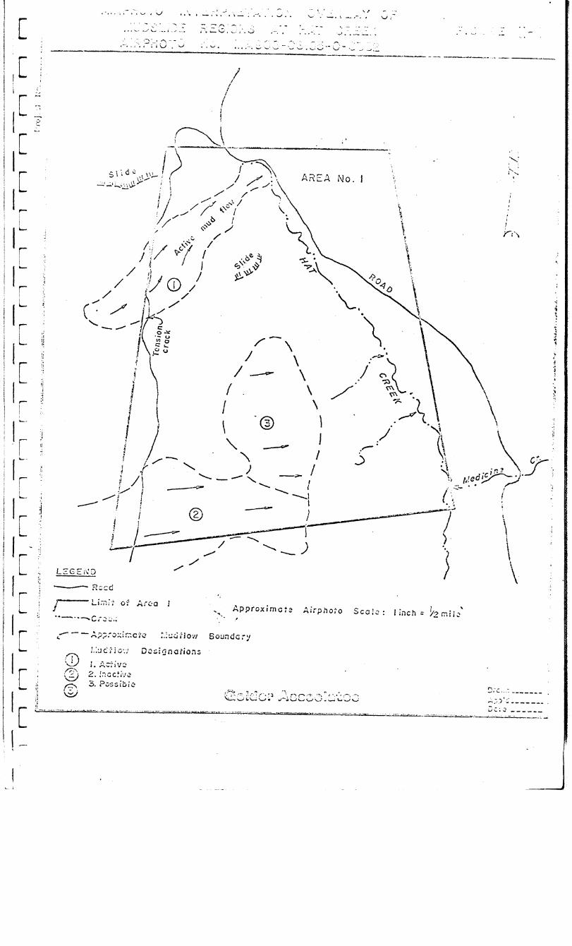


I
I
I
I
I
I
I
I
I I :
I
I
I I
I
I
I
I
I
I
m- L&Z ?ro?ossls-which follow are for both Stage II 2nd Stage III which
Y-~zT~."~ tcl zL-.e cetaiied feasibility assessnent of the miaicg area chosen for LF- LIiC
r . ccr.-As - - -7 ';: 2 &,EF& = 0: n1niTig at Eat Creek. These proposals are divided into three
s~c-,-;o,s:
(:) -kGsess~e--l" . . __ of stability of the superficial deposits, ixludi~~
cl-~ fnferred mudslides observed at the site.
i . .
(2) Zssessx-ent of stability of open pit slopes principally in the
CoidQra- 2' . w I sndke;l:s 2nd coal deposits.
(3 > :;;ydrology studies.
2 p ^ ', -: 7 2 - ,,G,__..-l~~ of Sc?erficial Slopes
To 2rovid.e 211 assessment of the stzbility of slopes iri superficial
-C*--Czr; L-CL-Z- *L&) the following questions have to be considered:
;a ,,L.r.L > :a--7 2 + 5s t:;e Iaterai extent and thfcknsss of sirc2 zzLeriais?
1 (0) !hac class 21-d kkd of rate-ri21.2re t>:ey cox~oset of?
(c) !;';-.at zre their shear strength charactc~istizs?
1 1 1. 1 1 I 1 3 1 3 1 1 3 3 3 1 1 -

f IC IC -I c I[ I[ I r L
I[
I r- L
I[
I[
Ii
I- i-
I c
I r L
I r L
I c
I[ ic I r L --
I
- A.33 -
T’1,2 estcrl+ c,ed cost for the above work would be $400,000.
In order to arrive at specific design conclusions on pit slopes, sLd2 .slo~ss
fez z-Y.2 access raz.2 and operatkg be;:ch2s, it is necessary to-log all existi7.2
axi - fqd;,ze (.oy2 for geotechnical infor-ation, to deterrcine structural orisatazioas,
c=:-?Y out detailed air photo interprezation and rock strength tests.
T=. - -L.liS info:;nation will be used to carry out d2tailed stability arC.ysas
on t;?S irOpOS2d pit SlO?SS.
T-.-.2 estimated total cost of t-a
c‘?..osl;li. pit site is $1,oo~,cco.
I- 16 -

i
I I I I
- A.34 - -. -
P Bock,
PrixipaI.~'Goid~r ..ksociates.
.c. _ 5 *- - , c:’
i. - - ,I,.‘..- .v.-i’. r-etu u.;iGz
- 17 -

IC I[: . IC IC .._ I[ . I[ i- I[: -. . I[ 7. I.[ _- I[ -_ IL -- I c - IL IL I[ I[ I[ I[ IL I7
SITE COL-ITIONS AN2 IWESTIGATIO3 PHILOSOTEY
LEVEL I - PRELI?ZW&Y h37DROLOGY STUDY
A. SCO?E
B. PROPOSED PROGRAM
C. TMING
LEVEL II - ?lINE FEASIBILITY HYDROLOGY STUDY
* . A. OBJECTIVE A22 SCOPE
B. METHOD OF APPROACH
c. DETAILS OF FIELD PROG&Ql
.
D. DETAILS OF DATA REDUCTION AND LABOMTORY PROGRAM
E. DETAILS OF AKALYTICAL PROGRAM
F. TINING
G. OUT?UTS AND PROJECT CONTROL ..’
LEVEL III - E3'VIRONENTAL BASELIm A2ZD PIT DESIGN STUDY
COSTING
EXPERIEXCE
AZ'PEmIX I Term of Reference
12PE&DIX II Details of Costing
A?PE?Z'i)IX III Schedule df Rates
AI'PENDIX IV Cirricula Vgtae
Gold?; Associates
.
.’
3
5
6
6
6.
6
9
-10
10
11
12
.13
3.3
13

- A.35 -
y;;c ;,p.\rci TT L 13 L’ 0 ,C, T;i.i>! i S L1 r;ore COi;!plCtC i;;ir?C fcnsibi.liry stsciy, _. I . . ..L. 1.;::: ~>l'O\~id~ hi:2 1~g’dr~lOgic iillTCIri;!;?tiOiI I:CCCSSr?l:y IOr prelixinnry :?.LilC
&SC,;;; zr,*< for 'ii:2 ilydrological envfronmcntal ixpact assessc~ent. The progr-cx ca.i;; . -2s complete by the end of Decer?Scr 1376, at a cost of about $1 ciilion. r- ‘- A..13 -'-- -..---. t~cll 52~2 a +J- Ua-ir... major ex?kasis on field testing for parameters, and s;:::>zsis of the results into the 'hydrologic siinulation models required for TLr.2 i2 s Lgr., stajilization strategy evaluation, and environmental irr?act assess- Zen;.
2-l. ill2 Level III progrz. is a follow-up program required for longer
tcrz ;--72 i-he-..^q L-7 . L-..--V..-.LC~-~C- ronitorixg, a;ld for detailed nine design. No tize or CGs, 2s;iTe?t2 fG=. tX.s level can be made at present, aithough such a Trograz vrz-Lt 32 ccnsiderakly smaller than t'r2 Level II program.
Zo1de-r 3rame-r & Associates Ltd. are ~211 suited to conduct this 3-'0"-~-- i- n ^ b . . , maying a Sritis'n Coi~uxSsian firn, with uniquely appropriate e;:?eriexe
* 1Tr la.-- - jl eilcrgy rr.l?. era1 hydrology and geotechnical studies.

- A.36 -
I 1 1 I 1 1 1
5~222 02 cz::?lstezess.

IC IC Ic IC , IL jr IC I[ I[ IL IL .I[ I[ .I[
I[ I[ (c
I[ I[ I
- A.37 -
,

- A.38 -
3.
-. ~,~F-,~ .: z-,.,7 3 f 2fiL-qe f-lab le 17 f o ‘i-.-! q- t i r,;: . .
A11 relevant inforjxatior, ojtzined in t3i.s ar.d precedent st::Zles
l.Jill 5e coliected and assessed. Data to be evahated will
ir.cl:.Ze geology, topography, neteorology, lithology, surface
hy?,ology, subsurface hydrology,. drilling logs, ~;eophyslc~L
iZZSY:L2tiOL, air ?i;c:to infr:yr?.ation, eater conductivity, ce~e:ials,
tats, and historical information. A considerable sxount or'
ts‘-: - Infomxtion has Leen ? . -3 2?,i;~~~~y asbm, *e 5' d by %hage, Ca~~?Leli
3 I.
7 -7 2r,c 3. c. 'liydro.
A Zield reconnaisance to the si te will be requi red to faxiliari2e
1 1 1 I 1 1 I 1 I I 1 I 1 1 1 1 I 1 1 -i

- A.39 -
I
1 I[ I I[
I[ (c Ii
I:[
- A.40 -
.

- A.41 -
--a 0 ;yzry’Ip3 .LaJy3 3CG?‘3
.--_ - -..c aIT. of t-22 Level Ii stcdy is to provide hydrologic iqut tc xin
I _ - : r_- i(:zea-. LT.C . 23s: 2s+-G-7-'ippa L .A...= L 'l5e data developed milst >e capable of defining
--e - -..c s.;-z 52 2 2 2nZ substirface hydrologic conditions T,r;, 23.. sufficient accurac:; t?.az
-;'- -.-..2 fCES-.: -: - 2 *-_ -.,---c~ can 3e evaluated 2nd an appropriate pit slope ar,d pit slo~z
ccl-mz-=,; -..- - -.--- *>- va3 c... caz 3e desiged and costed.

- A.42 -
T-- the fir-: three -v- of these activities a network of test welis wlli 1 3e reqii22l. We
J recommend the drilling of ten holes on or zear each of ZLQ .
zai, or sectLons, 7OOO'X and 15000'S, and additionally the use of six of the holes I -,roposel i:: other programs along the valley outline. Hole de??rh will typically
. 52 i,XN i22t on the t:~o sections, with the outer holes penetrating only 500 I z-2et. X2:.: criliin- will total aboilt 15 000 feet. 0 9 The arrangement of test hole-a
I is s'no:,n 52 ? * p9r2 1. '
;-iy-?zjl Y, a network of shallow holes ~31 be drilled near the trial ?L;;, 1
1 1 I 1 I I .I 1 , A

IC IC Ic ic I[
strategies.
TCe propose rhe perfornance of two such tests on t>.is site - oT,e

- A.44 - 1
D. DETAILS OF DATA REDUCTION AND LABOWTORY PROGRAM
during a long term pumping test can identify time dependent 1 behaviour parameters and further verify effective permeability
values. The installation of observation points along the two I sections utilized for packer testing is recommended.
4. Trial Pit 1
We understand that a trial open pit in coal is to be excavated 1 in order to obtain fuel samples. Details of this pit have not
been made available, however, we would propose to observe the 1 hydrological impact of this feature as it develops, and after 1 it has finished. Installation of observation piezometers in
shallow holes will form part of our study, and the results of 1 the investigation will be analysed using our finite element
method flow analogue capability. We would require involvement 1 in the planning stage of this trial pit if optimal hydrologic 1 information is to be obtained.
5. Detailed Field Reconnaisance
In addition to the above testing, a detailed field reconnaisance
will be undertaken to add to information currently available. 1 This will concentrate on locating springs, quicksand areas,
seeps, and other evidence relating to subsurface hydrology. 1 1 1
Analysis of information will be concurrent with collection of field a
information. The analytical activities will have as their aim the assembly of 1 a hydrologic model of the pit areas, and of the Hat Creek Basin.
1. Packer tests - deviation of permeabilities.
2. Pump Tests - analysis and simulation.
3. Piezometric information - refinement of simulator using 1
Golder Associates 1
i

IC
- - .
IL
, - - .
IC
r -
IL-
-_
Ic
7
Ic
7--
IL
- .
I [
I [
. - -
I[ --- I c
I r L r - I[ c- I[ . I[ I[ r I[ IL L- I[ .-- I
- A.45 -
observed values.
4. Geology/Geophysical and other information - assembly and input
to hydrology model.
5. Core permeability program - testing and estimation of actual
bulk permeability values,
E. DETAILS OF ANALYTICAL PROGRAM
The predictive hydrology model will be used to analyse situations of
mining hydrology significance. This phase will include analysis of hydrology
of various pit slopes under undrained and drained conditions, and evaluation
of the effectiveness of various water pressure reduction strategies. .
Analyses will be performed with the aid of our in-house 2 and 3
dimensional finite element method hydrology simulation capability, which has
been used with considerable effect on several recent hydrology studies of this
type l
F. TIMING
The program set out above as the Level II study will require an
elapsed time of one year. Of this, six months will be required for field
work, and a further non-concurrent four month period will be needed for the
completion of the analysis. We anticipate that mobilization will require an
elapsed time of between one and two months. Thus, it is reasonable to expect
that, if the study were initiated in January, 1976 it could be finished by
December, 1976.
It should be noted that a preliminary report could be prepared in
May, 1976, which would bo useful in making minability decisions. This would
include results of testing to that date and a preliminary version of the
Golder Associates -lO-
. .
- A.46 -
hydrology model for the basin. This report would probably fulfil some of the
early needs with respect to pit design and stability control strategy.
G. OUTPUTS Ah?) PROJECT CONTROL
In a project of this size and timespan a fixed series of check points
and coordination meetings are essential. We would propose that such a control
system be set up between B. C. Hydro, PD - NCB and ourselves prior to project
initiation. We have found in similar projects that monthly meetings'and
quarterly reports are usually fairly near optimal for good communication.
Golder Associates. .
- 11 - s
j
1 1 1 1 1 I
1 1 1 I 1 I 1 1 1 1 I 1
J

- A.47 -
At the conclusion of the Level II study there will remain two out-
standing study areas.
1. Environmental 1)aseline
The network of piezometric observation points developed in
Level II will be adequate for this purpose. Accordingly, all
that will be required for this program will be continued reading -\
of the piezometers and development of a body of baseline infor-
mation. This could readily be performed by personnel supplied
by the client, with occasional engineering input from Golder
Associates.
2. Pit Design Study
When specific pit locations are chosen it may be necessary to make
a more detailed study of the hydrology of the proposed pit walls.
We regard detailed planning and costing of.this phase as inappropriate
at this time. However , part of the Level II study will be to provide a program
for Level III.
Gofder Associates - 12 -

I -- I
1.
1. .-- iI. 1 - , II i II i i II
I I i
] r -
I
Ii
/ - -
iI
1-
/
I I
I
^ . .
I
I - . .
I
_ ^
I
. - .
I
r - .
I
c - .
- I
\ . - - . _
/ I
- A.48 -
COSTISG
Costing for the first two levels of this study has been estimated as
follotJs:
Manpdwcr Expenses' Total
Level I $ 10,550 $ 6,450 $ 17,000
Level II $368,000 $628,000 $996,000
Details of the way in which these figures were arrived at are included
in Appendix II.
PERSOXNEL
The key personnel involved in this project will be:
Principal and Project Director Dr. E. Hoek
Project Engineer and Senior Hydrologist A. Brown
Geologist K. Rippere
Computer Analyst I. Miller
Project Coordinator B. Brook<ng
Support personnel will be drawn from the resources of the Golder group
as necessary. Cirricula Vitae of the above personnel are attached.
EXPERIENCE
1 1 1 3 1 1 1 I 1 1 1 1 3 1
Golder Brawner & Associates has extensive experience of large hydrology4
projects for the coal and fossil fuel industries: . 1 - Morwell Open Cut, Victoria, Australia. Study involved assessment of
dewatering strategies for aquifers beneath a major lignite (brown I coal) mine, and slope stabilization in lignite and clayey overburde;.
Golder Brawner & Associates were also retained for hydrology 1
evaluation of the adjacent proposed Loy Yang Open Pit, which 1 Golder Associates I _ 13 -
u .,
\
i

- A.49 -
involved a major regional analysis of basin hydrology as well as
stabilization studies.
- Black Thunder Project, Wyoming (Eastern Powder River Basin). \
Evaluation of regional subsurface hydrology for input into stability
and environmental assessments for an open pit coal operation.
- Colorado Tract C-b Oil Shale Hydrology. Evaluation of mine inflow,
underground mine stability, regional'mine impact and environmental
baseline for subsurface hydrology.
- Carbon Creek Coal Project, B. C. Evaluation of undisturbed
regional subsurface and surface hydrology, and likely impact of strip
and underground mining on hydrology.
This specific experience is in addition to a broad association with .:
mining and civil engineering geotechnical projects throughout the world.
We trust that this proposal meets your present needs. Should you have
any questions, please do not hesitate to call us. . .
Yours very truly,
AB/jh A. Brown, P.'Eng.
v 75921
.
Golder Associates -.14 -


-- . rC .._ i i ‘I[ 1 Ii [ !- /i [ L. iI [ 1 --- ;i c I-- ; r :* I L ‘c C u- ?--- r ,i L- -[ I - c -I I :C f r -I i. - I I r --
{ I-- - t
APPEh3IX I
TERNS OF REFEREXCE
(Dated: 2nd September 1975)
.
. .

- A. 50 -
Provide eqineering services to ide;lti&^y the groundwater conditions that
could tifect the design ad deve1o;zer.t of an open?it coal mine in the
Hat Creek Valley. The survey icclwtiizg field investigations, evaluation
of laboratory analysis sd at",eZGtiCal zodelling is to be completed in
conjuxtioa with the Stse 3 detailed drilling progrm, the cining of a
coal sazqle, and the conceptual design of the tine. .
The assigraent is to include but not necessarily be -ited to the fol1ovir.g
considerations: . .
2.1
2.2
2.3
2.4
2.5
2.6
An estkate of the magnitude of groundvater flov rates.
h evahatio3 of cleft water and seepage presswe contitiox.
h evaluation of the groundxater table elevation acd its variations
due to clicatic charges such as spring thaw ar,d winter conditions.
An assessnent of the grousdwater flow response to surface
hydrogeological changes and the influence of surficial deposits,
vegetative covering and topography.
An investigation of the spatial and directional variations in
pemzeability of naterials in and around the opeqit.
The influence on grouzdwater conditions of mjor geological features
such as fault zones a;ld ixpemeable scans.
- I-l -
-.
1;
,
I * -
I - P
I . .
7
I-
I __
-
l-
I- r
I . .
- _..._
l- c
I -
l- -
I- --.
I --
I - . I .- -’ I ..~ I . ._. I I I ‘I---
- A.51 -
3.0 h!ctto~s to be coxldcrcd for obt.!a-iia~ a2d.assessir-g data are to include:
3.1 Titlc2 ;.!cnsurc~~n: Scrvc:;s .
- installation of piczoxters in dime-d drill holes :n and . .
ar0ur.d the designated openpit area for obtaining water pressure
data. Both short teAm and rernanent nonltoriw installations
are to be considered with ;?,'equency of readirgs depending-on
cha3@rG hydrogeolo~ic conditibns.
- pLTing, falling head and/or borehoie water packer pezzeability
. tests in diamond drill holes.
. - fle2.d measurezests as required to rmxtize the input of use,%
data generated prior to, during and after the excavation of a
test trench for rmoval of a coal test burn sazzle. Xeasure-
ments such as groundVater flows toward the excavation, required
pit dewaterirg and water level changes in surrounding boreholes
are to be included.
3.2 Araluation of Laboratory Analysis
- assessnent of the pemeability ofllsaterials in and around the
wenpit by evaluation of laboratory permeability tests on dimond
drill core and bulk sasiples.
3.3 @thezatical Xodelling
- nathezlatical simulation of groundwater flow.
- establishment of a control grid of piezoaeters to assess the
boundary conditions of the mathematical node1 and check
predictions of pressure distribution within and around the openpit.
- I-2 -
I
1 1. 1 : 1 1 i 1 1 I / 1 1 * 1 1 1 1 . . { I I ; 1 J j
1 I
1 / ! 1 i
1

- A.52 -
yzc as.5 i~r~~ent is to be cozz?lctcd in cooperation with the follo;ring ?lans
and schcdsles: .
4.1 sta SC 3 DriLlin;i - hL?;Ge CaTbell arid Associates Ltd. would be
Ean&irg contractor and geological consultants for a?proxizately
50,OW fee t of diamond drilling. !i3e detail drilling of the
selected openpit'is scheduled to cozence in November 1975 after
a decision is made whether to develop o;>enpit No. 1 or 2. A
mmku.zz of three billing rigs will be involved in the program
includiw geo$-iysical logging and related studies. .
. 4.2
4.3
4.4
Kinin,- ConceFtuzl Design - work will comence in Septmber 1975
and will require input freon the groundwater survey ti determine
the influence of gound%ater conditions on slope and pit base.
stability and dewatering requirerzents.
YLrLzg Coal Srlzle - a 50,060 ton coal sa@e is to be mined
betKeen Wrch and Y! 1976.
Iaboratory Analysis - both Dolcage Cmbell ar.d Associate; and the
System Design Division are azrazging for extecsive coal and over-
lying naterial analysis. Specific testing for pemeability,
porosity md other useful data for groundwater assessment ca.u be
arraged in cor&zctio;l kru &+h drill core and bulk smple analysis.
A cost esttite of the assigrzzea t is to be subzitted by 30 September 1975.
- I-3 -
.

2 Septcziber 1975
- I-4 -
1 1 d 7 J 1 1 1 1 i
1 .J
1 f
]
1 i
1
1 i
1
1
J
1 1 1 1 -
. .

APPENDIX II
DETAILS OF COSTIKG

i -.-- I([ j c-
,
:rC
! --
it- : - ;I[
-_ f-
.L I
.-
: Ic c-
.A[
- A.54 -
Details of costing are presente d for Level I and Level II of the program,
in order to indicate how totals were obtained. It should bc noted that actual
expenditures may not foliow this brcakdo:;n, due to changes in approach or
timing dictated by fi21d conditions. Tine information here should therefore be
regarded as informatory, rather than contractual.
Actual billing will be on the basis of the schedule of rates of the
Association of Engineers o f British Columbia, wit2 expenses re-billed to the
* client at cost plus 5 per cent handling charge, as set out in the attached
sheet (Appendix III).
A. LEVEL I
Costs are presented on a weekly basis, and include all anticipated
charges for the Level 1 study.
1. Review of Available Information
Senior Hydrologist - 1 week @ $1,20C/wk. $ 1,200.
Junior Engineer - 2 weeks @ $ 8OO/wk. 1,600.
Communications 500.
$ 3,300.
2. Site Visit
Senior Hydrologist - 1 week @ $1,2OO/i;k. $ 1,200.
Junior Engineer - 1 week @ $ 800/wk. 800.
Equipment (piezometers) 2,000.
Travel 200.
Accommodation 400.
Light Aircraft (Reconnaisance) 503.
Golder Associates - II-1 -

- A.55 -
3. TCSl:iilg and Anxllvsis
Senior Eydrologist - 1 week @ $1,200/~:~.
,7uilior i;;ngint? f: - 1 K?ek ? $ &-j()/[g:<*
Technician - 1 week @ $ 6OO/wk.
Computer Analysis .
4. Report
Senior Hydrologist - 1 week @ $1,20O/wk.
Junior Engineer - 1 week e $ 800/wk.
Draftsperson - 1 week @ $ 500/wk.
Typist - l/2 week @ $4OO/wk.
Reprographic (20 copies)
5. Management
Principal - l/4 week @ $1,80O/wk.
Communications
TOTAL (LEVEL 1)
$ 1,200.
800.
600.
2,000.
$4,600. .
$ 1,200. *
800.
500.'
200.
500.
$ 3,200.
$ 450.
350.
s 800.
$17,000.
B. L5vEL4 II
We have provided below a rough estimate of the order of cost of the
proposed Level II program. It must be remembered that:
a. Tne program outlined is likely to be substantially modified in
the light of the finings of the Level I study.
b. Field conditions may make sections of the program impossible
to perform and may require major modification to the proposed
program.
Go!der Associztes
- II-2 -
1 1 1 / 1 1 I 1 1 1 1 1 1 1 1 1 I 1 1 I

- A.56.-
The cost estimate is broken up into the same general sections as the
work, in order to show their relative contributions.
1. Field Program - Direct Costs
Drilling: 15,000. ft. @ $30/ft.
Packer Equipment Hire 100 @ $SO./test
Piezometers: 5 x 26 @ $100 (total)
Casing: 2 x 1000 ft. @ $20/ft.
Veil preparations: 2 x $15,000
2. Field Program - Personnel
Senior Engineer 1 x 25 weeks @ $1,2OO/wk.
Junior Engineer 1 x 50 weeks @ $ 8OO/wk.
1 x 25 weeks @ $ 8OO/wk'.
Technician 1 x 50 weeks @ $ 6OO/wk.
Per Diem, transport, communication etc.
($40/manday allowed)
3. Data Reduction and Laboratory Program
Senior Engineer 1 x 25 weeks @ $1,2OO/wk-
Junior Engineer 1 x 25 weeks @ $ 8OO/wk.
Technician 1 x 25 weeks @ $ 6OO/wk.
Computer Costs (lump sum estimate)
Golder Associates - II-3 -
‘.
$450,000.
$ 5,000.
$ 13,000.
$ 40,000.
$'30,000.
$538,000.
$ 30,000.
$ 40,000.
$ 20,000.
$ 30,000.
$ 42,000.
$162,000.
$ 30,000.
$ 20,000.
$ 15,000.
s 15,000,
$ 80,000.

- A.57 -
4. Analvtical Proqrna and Report
Senior Engineer 2 x 25 weeks 0 $1,20O/wk.
Juiiior Engineer 2 x 25 wesks @ $ SOO/wk.
Draftsperson 1 x 25 weeks @ $ 5OO/wk.
Typing/Clerical 1 x 10 weeks @ $ 4OO/wk.
Direct Report Cost 300 pp. @ $lO/page
Computer Costs (lump sum estimate)
5. I!anap,emsnt of Project
Principal 5 weeks @ $1,8OO/wk.
. Intermediate Engineer 50 m&s @ Sl,OOO/wk=
Communications, Travel, etc. *.
Total
$ 60,000.
$ 40,000.
$ 20,000.
$ 4,000.
$ 3,000.
$ 20,000.
$li7,000.
$ 9,000.
$50,000.
$10,000.
$69,000.
$996,000.
The total is comprised of $538,000 in direct drilling and well instal-
lation cost, and $458,000 in personnel and associated expense. We have added
the mar.agezent category as an 2splicit expense, and we regard the proportion of
managerical to engineering expense (7 per cent of total, 15 per cent of
personnel and associated ex-pense) as about optimal for a project of this size.
Goider Associates
- II-4 -
1 I I I 1
I
t
/ I t 1
1
1 i 1 1 I 1 1 1 1 ]
1 I ] 7 J I 1 ;

- H.St( -
APPEXDIX A
TERXS OF RZERIXCE FOR 1iAT CREEK !dINIXG STUDY
1. Provide engineering services to determine the feasibility
and cost of a mine to produce 12,million short tons per year
of coal for the 35 year life of a 2,000 MW thermal generating station. The normal maximum daily output of the mine would be 40,000 short tons.
2. The feasibility study shall include a preliminary assessment
of reclamation procedures. The cost of reclamation is con:
sidered part of the mining cost.
3. The consultant would assess the field work and exploration
to date.
. (a>
W
cc> The preparation of preliminary mine plans and sections.
WI Preliminary selection of waste and ash dump areas.
This data would be used for the following:-
Recommendation of further geological and
geotechnical work.
Recommendation of the area(s) and plan for detail
pit drilling to establish proven reserves and mineability.
4. A preliminary assessment of the mining costs shall be made
where information is adequate on the area(s) selected for
detail drilling.
5. The mine shall be equipped as necessary to deliver coal to
the thermal plant storage pile. Two alternatives shall be
considered:-
(a) Run of Xine with waste removed by selective mining.
- A.l.-

6. 1'arious open pit minin g methods shall be studied and compared 1 on the basis of cost, reliability and flexibility.
1 7. Coal cost estimates expressed in $/ton and $/ton and #/lo' Ztu '
are to be calculated for the methods studied. Capital cost estimates shall be broken down to clearly itemise the component I
costs.
8. Cost estimates shall be in 1975 dollars and shall be,broken
down by years. The interest on capital and interest during construction shall be taken as 10%.
9.
10.
11.
A project schedule shall be prepared on the basis of an'
earliest in-service date of the first generating unit of
January 1983 with capacity reaching 2,000 bW by April 1985.
The report should contain a study outline and recommendations
for further1 development of the mine including final mine site
selection, preliminary design, and final design.
Prepare and submit an interim report on Items 3(a) and 3(b)
by the end of November 1975L This report shail be based on geological and geotechnical assessments completed by that
time.
- A.59 -
(b) Coal mined and beneficiated. .I
Prepare and submit reports as follows:-
(a) Openpit X0 1 - in draft form by the end of February 1976 and in final form by the end of
March 1976.
(b) Openpit No 2 - in draft form by the end of April 1976 and in final form by the end of
May 1976.
In addition, brief monthly reports shall be submitted of activities and cost to date.
- A.2 -

- A.60 -
12. The successful execution of the work would require considerable
local knowledge with respect to labour, transportation and
legislation. The consultant would be required to carry out
the major part of the work in western Canada or establish an
affiliation with a suitable local company to ensure adequate
site dependent input.
13. The study is to be controlled and co-ordinated by the Assistant
General Manager, Engineering Group, of BC Hydro or his
appointee.
14. Provide budget capital es'timates as requested by BC Hydro
during the course of the study.
. .
- A.3 -

1 a
3 I I I I I I I -I I
a I I I I I
~ I *I *I *I 4
1 *.
2.
3.
4.
5.
6.
7.
S.
9.
10.
11.
12.
I_---- I
,-I
13.
14.
15.
16.
17.
TIiCYXCll CO21 RCSCdrCcS - Ii2t Creek, SUXYir\l~y RCDOrt SO 1 Openpit Deposit, DCA, 1 Jan 1975, *
So 1 Doposit Rock ?$echanics Data,' Klohn Leonoff CO3SUlt2nts Ltd. z Au2 1975.
So 1 Deposit Coal Quality Data, DCA, 27 June 1975. _
x0 1 Deposit Statistical Tables of Proximate Analysis Data, Dcd, 15 July 1975.
Ultimate and Kashability Data, DCA, 15 Sept 1975.
Xemorandum re Mining Costs, 23 Co Openpit,from .' Douglas D. Campbell to Dr. Ellis, 7 April 1975.
. Hat Creek Coalfield, BC Xinister of Mines ' Report, 1924.
Progress Report Xo 1, Xo 2 Coal Deposit, DCA, 19 Sept 1975.
Engineering Tests on Hat Creek Samples, Klohn Leonoff.Consultants Ltd., 12 Dee 1974.
Engineering Tests on H2t Creek Samples, Klohn Leonoff Consultants Ltd., 20 Jan 1975.
. . ‘Groundwater and Related Conditions in the .Upper Hat Creek Valley, Xemorandum from P.J. Street to Dr. D.D, Campbell, 25 Fe5 1975.
Hat Creek Project Progress Report, System Engineering Division BCH, Aug 1975.
Preliminary Environmental Impact Study of the proposed Hat Creek Development;BC Research and DCA, 1975.
Xemorandum on Hat Creek Exploration Programme Progress Report, BCH, July 1975.
Hat Creek - Coal Fired Thermal Power Plant, Feasibility Report and Cost Estimate (Report Ko 104>, BCH, July 1975.
Report on Pollution Control Objectives for the Siining, Xine-Xi lling and Smelting Industries of BC, Dept. of Lands, Forests and Water Resources, Dec. 1973.
Hat Creek So 1 Deposit Field Rock Slaking Tests, Winter 1975, origin not stated.
- B.l - .a
] I
‘3; I
1 ; 1 ~ 1 -4
1 , .J
-1 1. i
1 1 I J
1 .J : 7 J (
7 - i -7 :
. i
* I
J

? A. Loring Lzborzto-its Ltd., t?.nzlysis Z?eport So 10151,
DDE So 75-74, Sample Xc* 74-37 .and 74-41, Ott 1975.
7 d.
? e.
4.
5.
6,
7.
8.
9.
10.
11.
- A.82 -
P:~ovisional Geological Legend, 6 Xarch 1975. ,-
Record of Completed Di-ill IIolcs 1974, DDH 74-23 eo DDX 74-4S, and RI1 74-1 and Xf 74-2. ReCOl‘d ~i’ Complctcd Drill i!olcs 1075, DDii ‘75-49 to DCI! 75-61, and RI! 75-3 and RH 75-4.
Drill Record Sheets for DD:i 74-25, 74-48, 75-63,
75-49., 75-GS, 75-72, 75-75, 75-76, 75-77,
75-q 75-79,
75-S5, 75-88, 75-S9, 75-90, 75-91, 75-92, 75-93 l
.
Teles from Wrightenga 3 Nov 1975, giving drilling information of DDI-I 75-93, 75-94, 75-95, 75-96, 75-97, 75-98, 75-99, 75-100, 75-101, 75-102, 75-103.
Sepia copies of graphical logs for drill holes * . DDH 74-01, 74-02, 74-23, 74-24, 74~25~ .
74-26, 74-27, 74-28, 74-29, 74-30, 74-31, 74-32, 74-33, 74-34, 74-35, 74-36, 74-37A, 74-38, 74-39, 74-40, 74-41, 74-42, 74-43, 74-44, 74-45, 74-46, 74-47, 74-48, 75-03, 75-R4, 75-49, 75-50, 75-51, 75-52,.75-53, 75-54, 75-55, 75-56, 75-57, 75-58, 75-59, 75-60, 75-61, 75-62, 75-63, 75-64, 75-64A, 75-65, 75-66, 75-67, 75-68, 75-69, 75-70, 75-71, 75-73, 75-74, 75-77, 75-78, 75-798, 75-80, 75-82, 75-S3, 75-838, 75-84, 75-86, 75-87..
Prints of the above logs with the exception of DD% 75-68.
Roke Engineering Geophysical logs - sepia. ' : DDK RH 74-01, 74-02, 74-25, 74-26, 74-37A, 74-38,
74-39, 74-40, 74-41, 74-42, 74-43, 74-44, 74-45, 74-46, 74-47, 74-48, RH 75-03, RH 75-04, 75-49, 75-50, 75-51, 75-53, 75-56, 75-57, 75-53, 75-59, 75&O, 75-61, 75-62, 75-63, 75-67, 75-63, 75-69, 75-70, 75-71, 75-72, 75-73, 75-74, 75-76, 75-77, 75-78, 75-79, 75-798, 75-SO, 75-81, 75-S2, 75-S3, 75-84, 75-85, 75-87, 75-88, 75-S9, 75-90, 75-91.
Paper prints of each of the above.
Loring Laboratories Ltd., Analysis Report No 10636, . DDii 75-68, 20 Ott 1975.
Commercial Testing and-Engineering Company, Analysis Report No' 64-11201-11206, DDH 75-73, 3 xov 1975.
- B.2'-

; . .
: -i
I
r-
- _
I
-
_ -
I
. - d
I
--I
--i
-
I
- I
- I
- I
- I
. I
--
-
. I
--
I
-_
I
-
--
-1
-
- I
-4
-
- I
- . .
\
I
1’
12.
13.
14.
. 15.
16.
1s.
19.
20.
21.
22.
23.
- A.63 -
L01-i:;g LnSoratorics Ltd., Analysis Report So lOG33, DZi 75-74, 20 Ott 1975.
Loring Laborztorics Ltd., Annlysis Report so 10534) DZi 7%S2, 20 Ott 1975.
Loring LaboratoGics Ltd. Analysis Re_nort So 1037S, D3I! 75-53-401,'undated.
Uitimatc saqles col=:aini:lg internal unanalysed waste sections, DD3 75-57, 32A and Commercial Testing and Engineering Comna.ny, Analysis Report So 64-10450, 25 Aug 1975.
Ultimate samples containing internal unanalysed waste sectiorls ' > DDX 75-60, DCA and Commercial ' Testing and Engineering Company, Analysis Report No 67-10453, 25'Aug 1975.
. .
24.' .
Commercial Testing and Engineering Company, Analysis Report Xo 67-10456, DDH 75-61, 25 &lg 1975. .
. Loring Laboratories Ltd., Analysis Report 'No lOOS7, DDX 75-62, undated.
Ultimate samples coctzinlr?g internal unanalysed . waste sections, DDFI 75-68, DCA and Loring Laboratories Ltd., Analysis Report No 10090, . undated.
Ultimate samples containing internal unanalysed waste sections, DDH 75-73, DCA and Commercial Testing and Engineering Company, Analysis Report Xo 64-10732, 1 Ott 1975.
Loring Laboratories Ltd., Analysis Report . . 90 10464, DDX 75-74, 1 Ott 1975.
.
Commercial Testing and Engineering Company, Analysis Report Xo 64-10741, DDH 75-77, 1 Ott 1975.
Loring Laboratories Ltd., Analysis Report No 10465, DDH 75-SO, 1 Ott 1975.
Ultimate satiples containing internal unanalysed waste sections, DDH 75-S2 DCA and Loring
. Laboratories Ltd., Analysis Report Ko 10466, DDH 75-S2, 1 Ott 1975.
.
1 I 1 1 1 1
.. 1
1 1 :
1 1 i
J
1
-I
I* I 1
- B.3 _-
. .

- A.64 -
TLASS ASD S!:CTIOXS
1.
3 -.
3.
4.
5.
5
7.
S.
9.
10.
11; . .
.
i.2.
Transparencies and prints of topographical plans, scale 1 in = 400 ft, sheets 1 to 8.
Transparent plan of Xo 1 alld 2 areas showing topography, scale 1 in = 2000 ft.
Print .of plan showing drilling progress, period Aug 16 - 31, 1975, scale 1 in = 4000 ft.
Print of plan shozin g exploration areas, Stage 2c and 3a Drilling, Aug 1975, scale 1 in = 4000 ft . :
Print of plan showing Xo 1 Openpit Deposit Dril'l Holes, 1 Xarch 1975, scale 1 in ='800 ft.
Prints and transparency of plan Ha% Creek Exploratory Drilling 1975, July 1975, scale 1 in = 2000 ft.
Prints and transparency of No 2 'Deposit Drill Exploration, Sept 1975, scale 1 in .= 800 ft.
Prints and transparency of No 2 Deposit Geophysical Anomalies, Sept 1975, scale 1 in = 'SO0 ft.
Prints and transparency of BC Hydro Preliminary Stratum Contour Map, 24 June 1975, scale 1 in = 400 ft.
Geological Longitudinal Section Upper Hart Creek Valley, July 1975, scales 1 in = 2000 ft horizontal, 1 in = 500 ft vertical.
Sepia prints of cross sections on a scale of 1 in = 400 ft at 7ooos, 1ooOOs, 15OOOs, 165OOS, 19OOOS, 22OOOS, 25COOS, 3OOOOS, 7000X, and proposed drilling sections at 7OOOS, lOOOOS, 15OoOS, 165OOS, 19OOOS, 22OOOS, 25000s.
. Paper prints of sections on a scale of 1 in = 400 ft.- at 7OOOS, loooos, 150005, 165OOS, 19OOOS, 22OOOS, . . 25ooos, 30000s, 13500X, 10500X, 6500X, 3000X.
, :
.
- B.4 -

HAT CREEK Appendix C
BUDGETS -mcs).
1975-6 1976-7 1977~8..1978-9 1979-80 1980-1'1981-2 1982-3 1983-4 1984-5 _I_w
Geological Exploration of Preferred Pit Locations
Geotechnical Exploration a of Preferred Pit Locations 1 fiydrological Study
Geological Exploration to complete the Selected hline,Design
.Geotechnical Exploration to complete the Selected Mine Design
hIining Engineering to complete the Selected niine Design
Mining Equipment and Services
'Continuing Exploration and Geotechnical
Creek Diversion
(25 1:; (25) 25.X 25
50 : 556 g (1000) (1000) ';I 1040 1000
iii j (400) (500)
834 800
(600) (600) 600 600
NOTE: 1. 20th October budget shown in brackets for comparison.
2. All figures in 1975 prices.
.
.
(300) (300) (200) (100) (100) 300 : 300 300 300 300
. (1000) (1000) * .lOOO 1000
.
Incline Box-cut and Pre-production ,Ov~urQ11)Rernljal~sjo~ly)
(6300) (8200) (7000) ';;;"o) 6300 8200 7000
u / L-J .L.J u I u u UUUUU~~ I ._ -..--
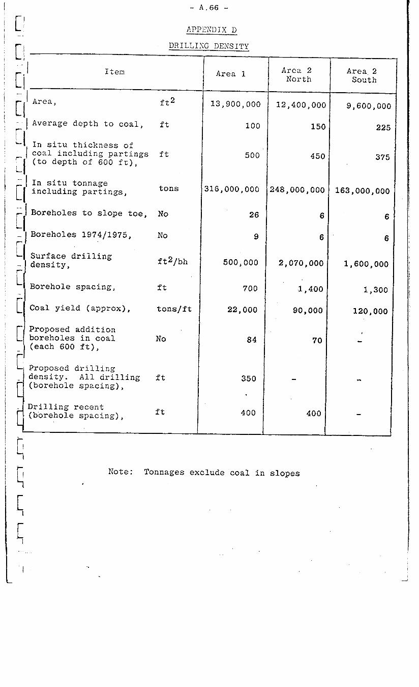
i
I L c -- r i - c c - C C F
In situ thickness of coal including partings (to depth of 600 ft),
In situ tonnage including partings,
Boreholes to slope toe,
Boreholes 1974/1975,
Surface drilling density,
Borehole spacing,
Coal yield (approx),
Proposed addition boreholes in coal (each 600 ft),
L' Proposed drilling
d density. All drilling (borehole spacing),
- A.66 -
APPZXDIiX D
DRILLIKG DEXSITY
1te;n Area 1
Area, ft2
Average depth to coal, ft
ft
tons 316,000,000 248,000,OOC 163,000,OOO
NO 26 E 6
NO
ft2/bh
ft
tons/ft
No
dDrilling recent (borehole spacing),
ft
ft
13,900,000 12,400,00(
100 15(
500 45(
9
500,000
700
22,000
84
350
.
400
6 6
2,070,OOO 1,600,OOO
1,400
90,000
70
400
Area 2 Area 2 North South
Note: Tonnages exclude coal in slopes ,
~~-
9,600,00(
22:
375
1,300
120,000
2


APPENDIX "B"
LIST OF DOCUMENTS AND DRAWINGS RECEIVED BY PD-NCB FROM 19TH NOVEMBER, 1975 TO
23RD FEBRUARY, 1976
Reports
(i) "Hat Creek Basin Gravity Survey", C.A. Ager and Associates Limited (data).
Geological Data
(ii)
(iii)
(iv)
(VI
(vi)
(vii)
(viii)
(ix)
(x)
(xi)
Approximate locations and intersections of DDH 111, 112, 112A, 113, 114 and 115.
E-W and N-S sections of No 1 coal deposit, 1 in to 200 ft.
Down-hole geophysical logs for drill holes 76-111, 112, 113, 115 to 119 inclusive.
Hat Creek drill progress location plan, complete for Stage 3A.
Geological logs for drill holes 75-105 to 75-110 (excluding 105A), and 76-111,112, 112A, 113 to 116 inclusive.
Geological logs (draft) for drill holes 76-117, 118 and 119.
Field slaking tests on cores from drill holes 75-60, 64A, 80, 84 and 87.
Record of completed drill holes, Table 1974 and Table 1975.
Geological logs for drill holes 75-79, 92, 96, 97, 101 to 110 inclusive.
Down-hole geophysical logs for drill holes 75-105, 107 to 110 inclusive.


c
--
.
.,
.
r-
. .
. .
r-
L.
i-
r-
L.
APPENDIX "C"
UNDERGROUND MINING
INTRODUCTION
1. It could become desirable to extract the lower portion of the No 1 coal deposit by underground means, Possible reasons for this could include:-
(i) Economically more favourable than continuing to opencast.
(ii) Too dangerous to continue deepening the openpit because of increasing slope instability.
RESERVES AND PRODUCTION
2. It is expected that the need to extract the coal by underground means would not occur until a~fter the initial pit to the 2,400-ft elevation has been completed. The quantity of coal remaining below the 2,400-ft level is estimated to be about 560 million tons.
3. The quantity required at the thermal power station for one year at that time would be 12 million tons. The estimated waste content for underground mining, which would necessarily be unselective mining, is 22% and therefore the annual tonnage of in-situ coal to be won would be about 15 million tons.
UNDERGROUND MINING METHODS
4. Mining the Hat Creek deposit by underground methods could only be done after an assessment of the following hazards:-
(i) Gas emission; ventilation of the areas being mined would vary depending on the mining method. Methane drainage might be necessary and might even be profitable if the methanewere supplied to the power station,
(ii) Spontaneous combustion; liability of the coal to spontaneous combustion would restrict the mining methods that could be used,
(iii) Strata control in conditions of weak rock, particularly slaking mudstones and groundwater.
5. Various broad methods of mining are examined further in the light of the above and other factors.
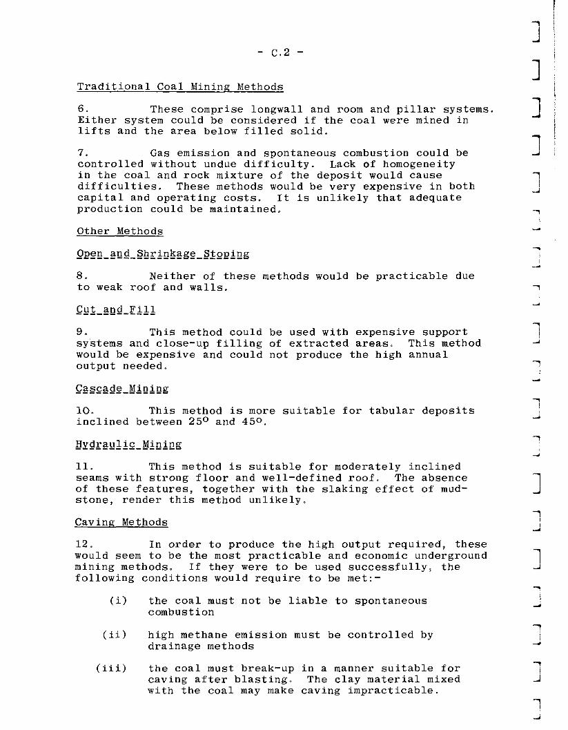
- c,2 -
Traditional Coal Mining Methods
6. These comprise longwall and room and pillar systems. Either system could be considered if the coal were mined in lifts and the area below filled solid.
7. Gas emission and spontaneous combustion could be controlled without undue difficulty. Lack of homogeneity in the coal and rock mixture of the deposit would cause difficulties. These methods would be very expensive in both capital and operating costs. It is unlikely that adequate production could be maintained.
Other Methods
8. Neither of these methods would be practicable due to weak roof and walls.
9. This method could be used with expensive support systems and close-up filling of extracted areas- This method would be expensive and could not produce the high annual output needed.
10. This method is more suitable for tabular deposits inclined between 25O and 450.
11. This method is suitable for moderately inclined seams with strong floor and well-defined roof. The absence of these features, together with the slaking effect of mud- stone, render this method unlikely.
Caving Methods
12. In order to produce the high output required, these would seem to be the most practicable and economic underground mining methods. If they were to be used successfully, the following conditions would require to be met:-
(i) the coal must not be liable to spontaneous combustion
(ii) high methane emission must be controlled by drainage methods
(iii) the coal must break-up in a manner suitable for caving after blasting. The clay material mixed with the coal may make caving impracticable.

- c-3 -
r.
.
7.
13, Both block caving and sub-level caving have high initial development costs but high production and productivity are subsequently possible, given suitable mining conditions. Control of the roof and sides would be crucial throughout mining and new methods, involving cable support of large exposed areas or other similar techniques, would need to be investigated, Closer control of blasting, mining and caving should be possible with sub-level caving rather than with block caving, therefore sub-level caving is considered further.
CONCEPTUAL METHOD
14. The area would be worked with four main shafts and four ventilation shafts, Levels would be at 300-ft intervals and coal would be blocked out on levels working downwards. A suitable block size would be 300-ft high by 300-ft long by 150-ft wide (625,000 tons). Each block wotild be split by sub-levels and coal loaded by front-end loader and shuttle car or load-haul-dump equipment into winzes leading to the level, This would be a typical sub-level caving layout. Detailed planning of the extraction procedure would enable 24 such blocks to be caved per year. To produce 43,000 tons per day would require 10 loading areas, requiring 350 men on a three-shift basis, but if, as expected, difficulty is experienced in supporting the shafts and roadways, considerably more labour would be required,
15. The problems of shaft-sinking alone would be formidable and weak rock material, structural weakness and water may well require freezing methods. Similarly, the problems of support of ore packs, main haulage roads, develop- ment roads, drain pockets, etc could well be insurmountable.
.,
r-
._
r-
L
.
r-
, .,.~
.


1. Inflation Rate (expressed as percentage) -
Year Labour and Materials
1975 base
1976 10
1977 10
1978 10
1979 10
1980 5 thereafter
Basic estimates are in 1975 dollars, without discounting, as stated in the Terms of Reference. The above inflation figures nave been used for inflated cash-flow curves and any other general statements or comparisons which have been necessary.
2.
3.
4.
5.
6.
7.
a.
Discount Rate -
evaluations carried out at 15%.
Power Costs -
an incremental energy cost of 10 mills/kWh has been used.
Interest During Construction Calculation -
IDC in year N is half the interest rate x the Nth year capital cost, plus the interest rate x the accumulated expenditures, including previous IDC in the preceding N-l years. I = 10%.
Corporate Overhead Rate -
A corporate overhead of 5% has been added to the uninflated direct costs of the project (see Plate 42).
Tax and Debt Equity Ratio -
Assumed that no tax paid by EC Hydro and that financial structure is 100% debt.
Sales Taxes -
Federal sales tax of 12% not applied on generator or mining equipment used for power generation. Provincial sales tax omitted.
The Provincial Royalty -
APPENDIX "D"
BASIC FINANCIAL DATA
Assumed to be 756 per long ton (equivalent to 67d per short ton).

APPENDIX "E'!
LABOUR REQUIREMENTS
MINE LABOUH FORCE
1. The mining labour requirements and associated wage costs related to the development and operation of the mine, but excluding building and construction work, are shown in Table XVIII. There is gradual build-up in the mine labour force to some 660 employees by the end of stage 6, each major sec~tion of the mine operation being as follows:-
Mobile mining equipment 500
Fixed installations 130
Infrastructure 32
._
r-
r-
-
. .
L”
r-
-.
r-
L-~
r-
. .
r-
.
Total 662
2. This total requirement increases to 987 during stage 7 and subsequently to 1,148 at the beginning of stage 8, all of the projected increase occurring in the mobile mining equipment section.
3. Although there are upwards of ten labour grades in most current union contracts, in Table XVIII these have been simplified into the three main categories given below, the percentage figures relating to the relative proportions of each at .stage 6.
Equipment operators - 53%
Maintenance personnel - 37%
General mining labour - 10%
4. The wage rates are in line with those pertaining to current mining contracts in the general area, These would seem to be slightly lower than those paid in some of the coal mining operations in the Eastern Kootenays so it is possible that some upward revision might be necessary, depending on the particular union contract. In this respect, it must be emphasised that the type of mining envisaged is closer to that practised in metal mining so that local mining traditions could have a greater influence on rates and'conditions than coal mining traditions in other areas.
MANAGERIAL, TECHNICAL AND ADMINISTRATIVE STAFF
5. The numbers of managerial, technical and administra- tive staff relating to each stage of the project are shown in Table XIX.
-

- E.2 -
I 6. In developing the schedule it has been assumed that the mine will be operated as a captive mine and that BCH will provide the corporate planning, marketing, financial and data processing functions from head office. Again the salary costs would seem to be in line with those currently paid at other mines in the general area. It should not be overlooked, however, that the projected rapid growth in coal mining in Western Canada will cause demand for senior coal mining personnel to exceed supply and that severe upward pressures on coal mining salaries could result.
1 1
J

Explanatory Note
There are a number of minor discrepancies in the following
tables which are, however, without significance in the con-
text of the conceptual design and the level of confidence
of the estimates.
-

. .
..-
is
r-
L ,.
7
.
7
r.
,,-.
,--
.
r-
r-
--
.
L
L.
c~
h.
.
L.
r.
.~
TABLE I
BASIC PLANNING DATA
Density of in-situ coal - 1.39 short tons/bank yd3
Swell - 25%
Density of in-situ waste in coal - 1.87 short tons/bank yd3
Swell - 50%
Density of ROM coal - 1.29 short tons/bank yd3
Density of superficial deposits - 1.56 short tons/bank yd3
Swell - 15%
Density of claystone (assumed wet) - 1.87 short tons/bank yd3
Swell - 40%
Density of conditioned ash - 1.2 short tons/yd3 (loose)
Estimated in-situ waste content - 22%
Estimated waste extraction by selective mining - 15%
Waste remaining in ROM coal - 7%
Working days per year - 350
Hours per shift - 8
Teams of men - 4
No of producing shifts per week - 20
NO of maintenance shifts per week - 1
J

A. Referred to In situ Coal


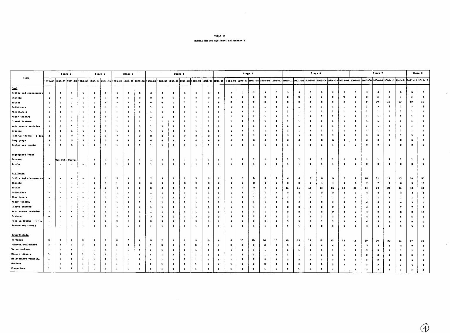


c
TABLE VI
SCHEDULE OF TYPICAL EQUIPMENT
Category Type Manufacturer ivodelj Capacity
, Shovel Electric Bucyrus Eyrie 195 !15 yd3
Drills Compressed Air Gardner Denver 31OOA.4-in holes
Compressors Diesel Gardner Denver SP600 600 ft3/min
Off-highway trucks Diesel Wabco 150 C 117 tons coal
Bulldozers Diesel Caterpillar D9H
Wheeldozers Diesel Caterpillar 824
Graders Diesel Caterpillar 16G
Scrapers Diesel Caterpillar 666 41 bank yd3
Compactors Diesel Caterpillar 825
Water tanker Diesel Caterpillar 631 lO*OOO US gals i
Note : The manufacturer's name and the model numbers have been given to enable production details and costs to be specified concisely. They are not intended to indicate any preierence.
-

TABLE VII
MOBILE MINING EQUIPMENT - COST ALLOCATION
Activity
Superficials
Pit waste
Coal extraction
Segregated waste
$ Total cost
25
47
24
4
100
Machine Type
Shovels
Trucks
Scrapers
Drills and compressors
Bulldozers
Sraders
Whers
W Total cost
11
51
19
4
6
4
5
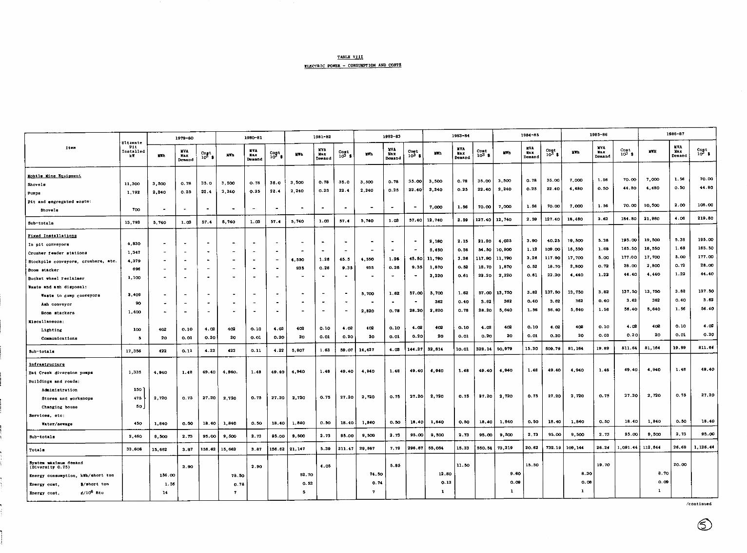


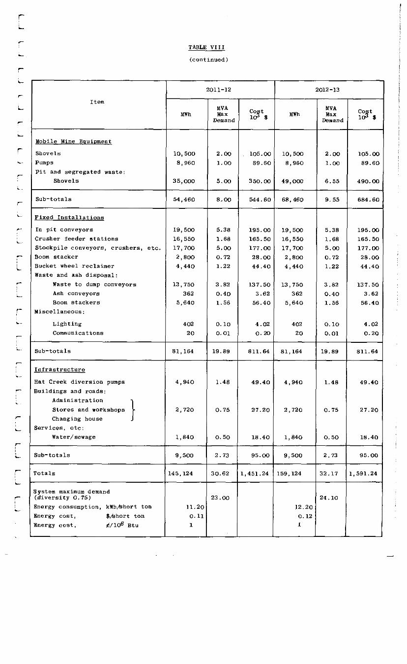
Item
MWh
2011-12
MVA Max
Demand
co 12 t 8
2012-13
MVA MWh Max co t
Lkmand ld s
Mobile Mine Equipment
Shovels 10,500 2.00 105.00 10,500 2.00 105.00
Pumps 8,960 1.00 89.60 8,960 1.00 89.60
Pit and segregated waste:
Shovels 35,000 5.00 350.00 49,000 6.55 490.00
Sub-totals 54,460 8.00 544.60 68,460 9.55 684.60
Fixed Installations
rn pit conveyors 19,500 5.38 195.00 19,500 5.38 195.00
Zrusher feeder stations 16,550 1.68 165.50 16,550 1.68 165.50
Stockpile conveyors, crushers, etc. 17,700 5.00 177.00 17,7OC 5.00 177.00
Boom stacker 2,800 0.72 28.00 2,800 0.72 28.00
Bucket wheel reclaimer 4,440 1.22 44.40 4,440 1.22 44.40
Waste and ash disposal:
Waste to dump conveyors 13,750 3.82 137.50 13,750 3.82 137.50
Ash conveyors 362 0.40 3.62 362 0.40 3.62
Boom stackers 5,640 1.56 56.40 5,640 1.56 56.4c!
Hiscellaneous:
Lighting 402 0.10 4.02 402 0.10 4.02
Communications 20 0.01 0.20 20 0.01 0.20
Sub-totals 81,164 19.89 811.64 81,164 19.89 811.64
infrastructure
iat Creek diversion pumps 4,940 1.48 49.40 4,940 1.48 49.40
3uildings and roads:
Administration
Changing house I
Stores and workshops 2,720 0.75 27.20 2,720 0.75 27.20
k-vices, etc:
water/sewage 1,840 0.50 18.40 1,840 0.50 18.40
sub-totals 9,500 2.73 95.00 9,500 2.73 95.00
:ota1s 145,124 30.62 1,451.24 159,124 32.17 1,591.24
iystem maximum demand rdiversity 0.75) 23.00 24.10
lnergy consumption, kWhbhort ton 11.20 12.20
energy cost, $,%hort ton 0.11 0.12
<nergy cost, t!/l@ St" 1 1
-
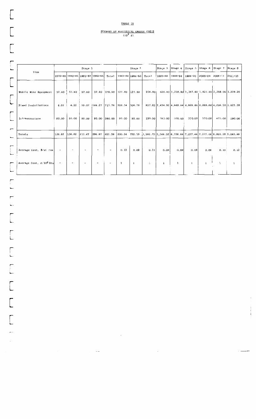
c C r-
stare 2
-


r T T ,L t s 10 T s 10
e C”
f
IQ 5
659
-
-

Dump Elevation
ft
<2,800
2,800-2,9OC
2,900-3,ooc
3,000-3,lOC
3,100-3,2oc
3,200-3,3OC
3,300-3,4oc
3,400-3,5oc
3,500-3,6OC
3,600-3,7OC
3,700-3,soc
3,800-3,9oc
3,900-4,ooc
TABLE XII
DUMPING SPACE A_VAILABLE AT 100-FT INTERVALS
(lo6 yd3)
Dump No 1
17
7
22
14
45
15
29
28
30
37
43
49
57
Cum.
24
46
60
105
149
177
207
244
287
336
393
hmp No 2
72
165
176
216
64
136
227
476
627
968
jump No 3
27
32
128
Dump No 4
244
:um
8
89
189
332
.,080
24
69
136
231
306
526
Total
196
332
469
662
L,199
L;576
?,030
?,556
1,172

TABLE XIII
HAT CREEK DIVERSION COSTS
Description Unit Quantity Rate Amount
$ $ Earth Da~m (140,000 yd3)
Stripping dam area yd3 1 8,000 1.50 12,000
Main body dam fill Yd3 j 106,000 2.00 .212,000
Filter material yd3 ; 22,000 / 4.00 88,000 !
Impervious zone yd3 I 14,000 1 3.00 , 42,000 ! 1 !
Engineering and I I contingencies i I 1 i 86,000
I I /
Sub-total ~440,000
I Pumping 1
Pumps and motors, 9,000 gal/min, VTP, 600 hp, 1,180 rev/min, to include starters and pump columns each 5 50,000 250,000
Pumphouse ft2 400 40.00 16,000
Butterfly valves, 18 in centre-line AA-M, includes operator gear each 5 1,800' 9,000
Check valves, 18 in Atco 618 each 5 3,000 15,000
Pressure relief valves each 2 4,000 8,000
Pump control valves, 10 in Clayton 2061 PA each 5 2,900 14,500
Miscellaneous fittings lump sum - Allow 6,000
Electrical switchgear lump sum - , Allow 5,000
Powerline to pumphouse transmission, circuit breaker, etc mile 1.3 69,000 90,000
Pump tower lump sum - I
Allow 20,000
Miscellaneous lump sum ) 135,000
Engineering and contingencies 1
I j142,oOO
i
Sub-total j710,OOO I
/continued

.-
i
r-
r-
r- i..
c
r c_
r . .
TABLE XIII
(continued)
Description Unit : Quantity Rate / Amount 1 I
I ; $ j $
Watery Pipelines to 1 ! Drainage Channel L
2 x 2,100 ft of 30 in I I dia. steel pipe allowing 1.5 for water hammer. Wall thickness 0.250 in lb I
1
337 ' 000 0.65 219,000
Miscellaneous and additional pipe ! 135,000 Engineering and 1
contingencies I I
3 I 89,000
Sub-total 443,000
! Drainage Channel /
IO by-pass main pit yd 3 I ; 15,ooo 1.50 22,500
drainage channel lining yd3 i 2,000 5.00 10,COO
Eock protection rip-rap I
at drainage channel lutlet yd 31 ; 150 20.00 3,000
:oncrete lining at
:hannel inlet yd3 i 20 50.00 1 lam discellaneous
engineering and zontingencies I I l"'ooo 11,500
lub-total 58,ooO
hnergency Overflow Weir
Concrete weir and abutment walls yd3 100 150.00 15,000
:xcavate channel open yd3 2,000 2.00 4,000
:hannel lining , yd3 400 5.00 2,000 I
/continued

r L
r I
r L
r i
r i..
r
c,
TABLE XIII
(continued)
Description Unit Quantity Rate Amount
$ $
Rock rip-rap and channel cobbling yd3 50 20.00 l,(JOcJ
Install 72 in dia. CPM I culvert / lb 30,000 ' 060 18,000
Miscellaneous I 36,000 I
Engineering and I
contingencies I 21,000 / !
I Sub-total 97,000
1 /
Diversion of Small Stream Below Dam I / Allow 2,000
I /
Total Cost for Hat Creek Diversion 11,750,OOo

TABLE XIV
BAT CREEK SURFACE DRAINAGE COSTS
Description Unit Quantity Rate Amount
$ $
Excavate ditches Lin ft 301000 1.00 30,000
Minor drainage, works, allow lump sum 5,000
Clear bushes, trees- grad- ing; etc lump sum - 5,000
Engineering and contingencies 10: 000
Total for Surface Drainage 50,000

TABLE XV
HAT CRFEK ROAD RF-LOCATION COSTS
Quantity ; Rate
Stripping of turf and topsoil and dumping
Cut to fill
AddItional cut for rock encountered
Cut of ditches
Base. course layer at,: say, 1%in thickness
Culverting layer. l&in diameter, Armco- 12 gauge
Culvert over Hs.t Creek
Engineering and contingencies
Total for Hat Creek Road Re-Locatioc

TABLE XVI
SURFACE MINE BUILDINGS AND HOUSING COSTS
Description Amount 8
Surface Mine BuildinKs
Administration office
Change house
Maintenance bays, workshops and warehouse with equipment and tools
Core shed
Powder magazines
Total Surface Mine Buildings
Single Work Force and Senior Staff Camp
Eleven 40-men bunkhouses
Eleven recreational units
Kitchen-diner
First aid
company store
Sewage treatment for both camps (half of full price)
All services (electrical, sewer, gas, water)
Power generator for both camps (half of full price)
Single work force camp
Senior staff camp
Total Single Work Force and Senior Staff Camp
Permanent Housing
Manager's house
Senior staff houses
Basic houses
Town houses
Apartments
Total Permanent Housing
286,000
236,000
3,805,OOO
4,m
20,000
4,351,ooo
770,000
172,GcJo
56,000
5,000
20,000
25,000
51,000
75,000
1,174,ooo
427,m
1,601,OOO
75,000
1.496,OOO
5.859,Ooo
1,404.m
1.360,OOO
10.194.000
-

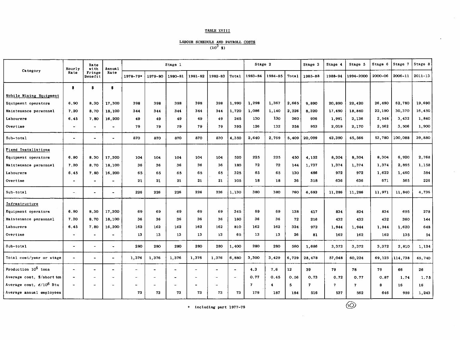

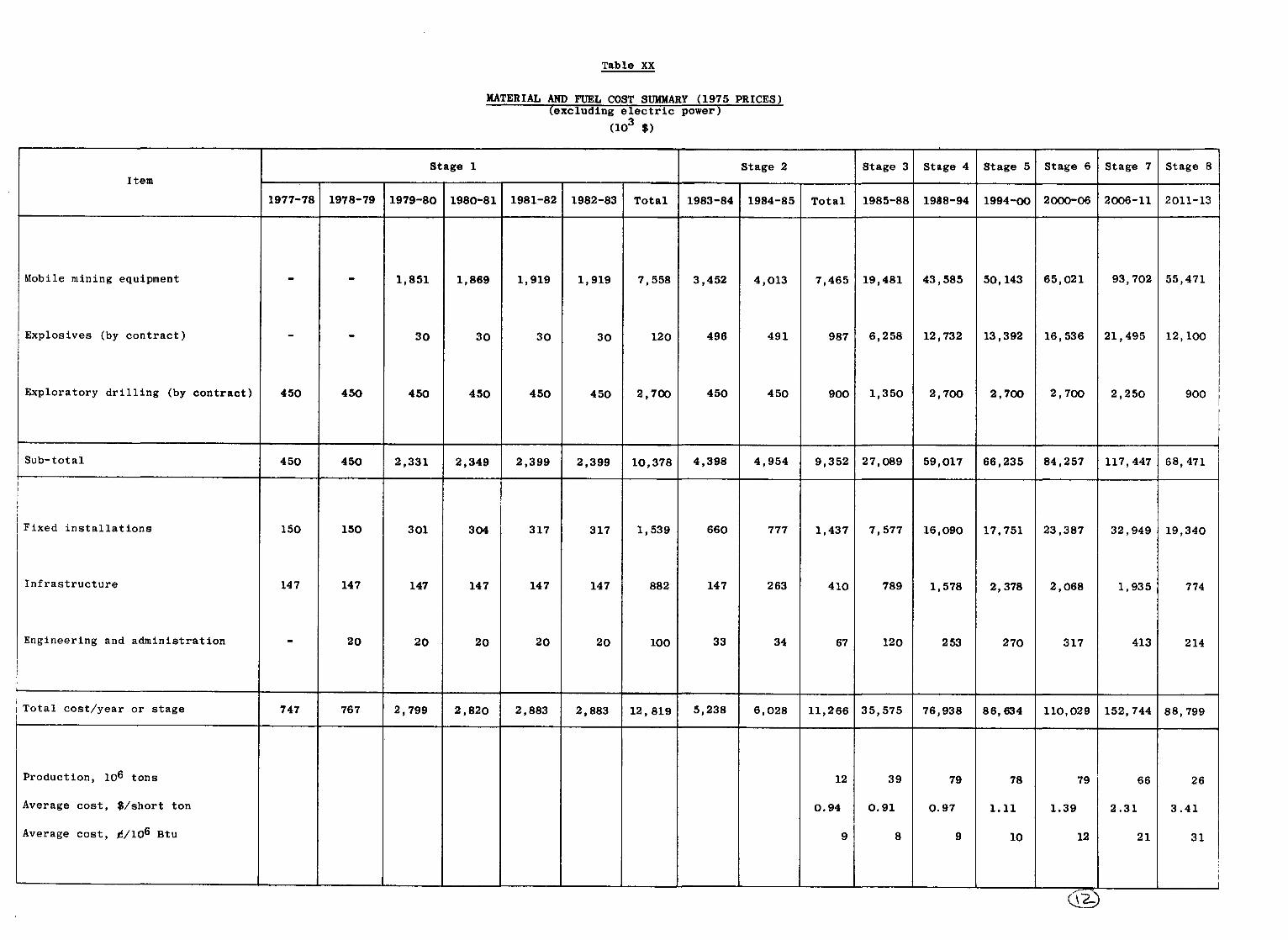


C C C c
r i