PCU-10 Display and Controll Unit red-y smart series Display and Controll Unit for red-y smart...
42
Vögtlin Instruments AG – flow technology Langenhagstrasse 1 | 4147 Aesch (Switzerland) Phone +41 (0)61 756 63 00 | Fax +41 (0)61 756 63 01 www.voegtlin.com | [email protected] Handbuch PCU1000 red-y smart series operating instructions PCU-10 Display and Controll Unit for red-y smart series
-
Upload
truonghanh -
Category
Documents
-
view
229 -
download
4
Transcript of PCU-10 Display and Controll Unit red-y smart series Display and Controll Unit for red-y smart...

Vögtlin Instruments AG – flow technology
Langenhagstrasse 1 | 4147 Aesch (Switzerland)
Phone +41 (0)61 756 63 00 | Fax +41 (0)61 756 63 01
www.voegtlin.com | [email protected]
Handbuch PCU1000
red-y smart series operating instructions
PCU-10 Display and Controll Unit for red-y smart series

red-y smart series
Manual Version Page
PCU-10 PCU-10_E2_1 © Vögtlin Instruments AG 02
Version: PCU-10_E2_1
For the latest information on our products, see our website at www.voegtlin.com
© 2011 Vögtlin Instruments AG, Switzerland
Operating instructions PCU-10
for red-y smart series General operating instructions
red-y smart meter GSM
red-y smart controller GSC
These instructions are only valid for smart devices from serial number 110 000 and above

red-y smart series
Manual Version Page
PCU-10 PCU-10_E2_1 © Vögtlin Instruments AG 03
1.1 Important Instructions
Before and installing and operating the instrument it is strongly recommended that this operation
manual should be read carefully. Not following the guidelines could result in personal injury and
damage of equipment.
The content of this manual is provided for information only and may be altered without prior notice.
Voegtlin Instruments AG assumes no responsibility or liability for any errors or inaccuracies in this
manual.
This symbol alerts the user to important operating, maintenance and service infor-
mation.
Installation
Prior to commissioning please note the following
Only the supply voltage indicated on the nameplate is permissible
This device must be grounded.
The power supply is 100…240 VAC / at a maximum of 1.3A
If a PDM-U cable is being used, do not connect an additional 24 volt power supply.
Products mentioned in these instructions can contain metal or elastomer gaskets, O rings or valve
intakes. It is the user’s own responsibility to select only such materials that are compatible with the
process and the process conditions. The use of non-compatible materials can cause leaks in the
gaskets of devices which could permit gases to escape from the device – which in turn can lead to
health hazards and death.
We recommend checking the smart devices at regular intervals to ensure that leakage has not
occurred. The metal or elastomer gaskets, O rings and valve intakes change with age and thus
release gases due to leakiness.
Important instructions
Do not remove the cover - it prevents damage to the system. In case of a damaged holo-
gram seal the warranty expires.
There are no serviceable parts under the cover
Repairs must only be performed by qualified personnel

red-y smart series
Manual Version Page
PCU-10 PCU-10_E2_1 © Vögtlin Instruments AG 04
Toxic, flammable gases and ATEX
In the case of toxic and flammable gases, the safety guidelines of the respective country
must be followed. The red-y devices are not approved for use in Ex- zones. In the case of
flammable and toxic gases, fittings and pipes intended for that purpose must be used. The
responsibility for safe operation lies with the designer of the facilities. The devices must not
be used in areas containing explosive mixtures.
Removing a device
Before removing a smart device from installation the power supply of the measuring instru-
ment must be switched off.
Troubleshooting
Problems with the system usually have manifold causes. Therefore Vögtlin recommends consulting
both the operating instructions of the original equipment manufacturer as well as our operating
instructions before removing the measuring instrument from the system.
Please read also chapter “Troubleshooting” in the general operation manual mass flow meter and
controller, part 1.
The equipment fulfills the regulations according to CE.
Recycling
Please observe the applicable regulations of your country.
Subject to change
Due to our policy of ongoing product development, we reserve the right to change the information
in this manual without notice. All rights reserved. No part of this publication may be reproduced in
any form or by any means without the publisher's prior written permission

red-y smart series
Manual Version Page
PCU-10 PCU-10_E2_1 © Vögtlin Instruments AG 05
Contents
1 Introduction 6
1.1 Purpose of the Operating Instructions ........................................................................................... 6
2 Commissioning 7
2.1 Initial Inspection ............................................................................................................................. 7
2.2 Important Instructions for supplying gas ........................................................................................ 7
2.3 Connecting the System .................................................................................................................. 7
3 Main screen 8
3.1 Main Screen Offline ........................................................................................................................ 9
3.2 Main screen for MFC-Control ....................................................................................................... 10
3.3 Main screen for Master-Slave ...................................................................................................... 20
3.4 Main screen of the Mixer function ................................................................................................ 24
3.5 Main Screen of the Burner Controller .......................................................................................... 31
4 Registering new MFCs 37
5 Repair Instructions 39
6 Installation Guide for Frontpanel Version 39

red-y smart series
Manual Version Page
PCU-10 PCU-10_E2_1 © Vögtlin Instruments AG 06
1 Introduction
1.1 Purpose of the Operating Instructions Working with gases, in particular with flammable and/or toxic gases, requires maximum caution.
Therefore reading and understanding these operating instructions prior to the installation and
commissioning of the PCU-10 is imperative, so that errors in operation can be excluded.
The operating instructions should always be available to operating personnel. Following the operat-
ing instructions helps avoid risks, minimizes downtime caused by operating errors and ensures the
service life and reliability of the PCU-10.
The complete operating instructions should be read carefully prior to installation and commission-
ing.
If unexpected malfunctions occur which cannot be remedied even with the help of the operating
instructions, please contact us specifying the device number (see technical data) or fax us the
technical data sheet of these operating instructions with a brief description of the error. Please re-
member to list your name, the name of your company and your telephone number.
In the event of modifications to the PCU-10 these operating instructions lose their validity!

red-y smart series
Manual Version Page
PCU-10 PCU-10_E2_1 © Vögtlin Instruments AG 07
2 Commissioning
2.1 Initial Inspection The PCU-10 comes programmed and ready for connection. Prior to setup and installation you
should check the delivery for shipping damages. If damages have occurred, do not operate the
PCU-10. Inform customer service or the manufacturer immediately. The PCU-10 is to be transport-
ed using the appropriate means and should be protected from tipping or water damage. Be sure to
set it up on a level surface.
2.2 Important Instructions for supplying gas The respective gases may only be supplied to the gas mixture and regulation system via the ap-
propriately designated gas connections. The system itself must be tested for leaks.
On the gas supply side of the system make certain that the maximum permissible supply pressure
is not exceeded.
Only then should you operate a gas mixture and regulation system with the PCU-10.
2.3 Connecting the System External electrical connections, if required, should only be performed by professionals.
Warning: The length of the cable provided by the factory may only be altered upon consultation!
1. Use the supplied connector plug to connect the device to an appropriate socket with grounding contact 230V / 50 Hz.
2. A sufficiently sized power supply is built in the device for operation of the devices
(230V AC / +24 V DC).
3. Use the ON/OFF switch on the rear to switch the device on.

red-y smart series
Manual Version Page
PCU-10 PCU-10_E2_1 © Vögtlin Instruments AG 08
3 Main screen After you switch on the device the version number of the software installed on the micro-controller is briefly displayed on the screen. In case of malfunction, please mention this number.
After that the main screen typical for the set operating mode (Op Mode) appears. The currently selectable operating modes are the normal GSM/GSC controller under the name „MFC-Control“, a master-slave mixer controller under the name „Master-Slave“, a general gas mixer controller under the name „Mixer“ as well as a special burner controller under the name of „Burner“. In addition, an „offline“ function is also available. If the device is switched to offline mode, it contin-ues to supply the connected MFC and GPC with power, but no longer communicates with the con-nected devices. For example, this makes it possible for a PC to control the connected MFC and GPC via a PDM-U cable. A separate connector is present on the rear of the device for connection of the PDM-U ca-ble. The PDM-U cable in this case is supplied with power from the PCU-10 and there must be no power supply connected to the round connector of the PDM-U cable.
All the different main screens have the following in common: in the bottom right corner a „Menu“ button is displayed with which you can carry out the basic functions important for the re-spective operating mode (if present). You can also use this button to change operating modes.

red-y smart series
Manual Version Page
PCU-10 PCU-10_E2_1 © Vögtlin Instruments AG 09
3.1 Main Screen Offline The main screen of offline mode displays the following text in the middle of the screen „Offline, MFCs may be handled from other bus controllers“. Apart from that you will only see the „Menu“ button in the lower right corner.
The menu, which opens when you select the button, only allows you to set the brightness of the display (Brightness) and change operating modes (Op Mode).

red-y smart series
Manual Version Page
PCU-10 PCU-10_E2_1 © Vögtlin Instruments AG 10
3.1.1 Op Mode
Basic operating mode of the controller
0 = Offline 1 = MFC-Control 2 = Master-Slave mixer 3 = General Gas mixer 4 = Burner controller
3.1.2 Brightness
Sets the brightness of the display.
3.1.3 EXIT
When you exit this window you return to the main screen
3.2 Main screen for MFC-Control In addition to the menu button there are other buttons whose captions give you information about the set operating mode.1 For example, if you see one or more buttons labeled with „A“ and a num-ber, as shown below, you are in „MFC-Control“ operating mode. This operating mode allows users to set each of the connected devices to a setpoint or to read its actual values without having the individual devices be in a specific logical relationship to one another.
In the „MFC-Control“ operating mode each button stands for a single registered MFC (Mass Flow Controller), MFM (Mass Flow Measurement) or GPC (Gas Pressure Controller). The number after the „A“ is identical to the address of the MFC, MFM or GPC. Each connected device must have a unique address in the system via which it can be addressed by the PCU-10. The micro-controller
1 If you do not see any other buttons, it means no MFCs are „registered“ on the device. In this case read the
section „Registering new MFCs“
red-y smart series
Manual Version Page
PCU-10 PCU-10_E2_1 © Vögtlin Instruments AG 11
ensures that these addresses start with „1“ and are sorted in continuous ascending order. You can find more information about this in the section „Registering new MFCs“.
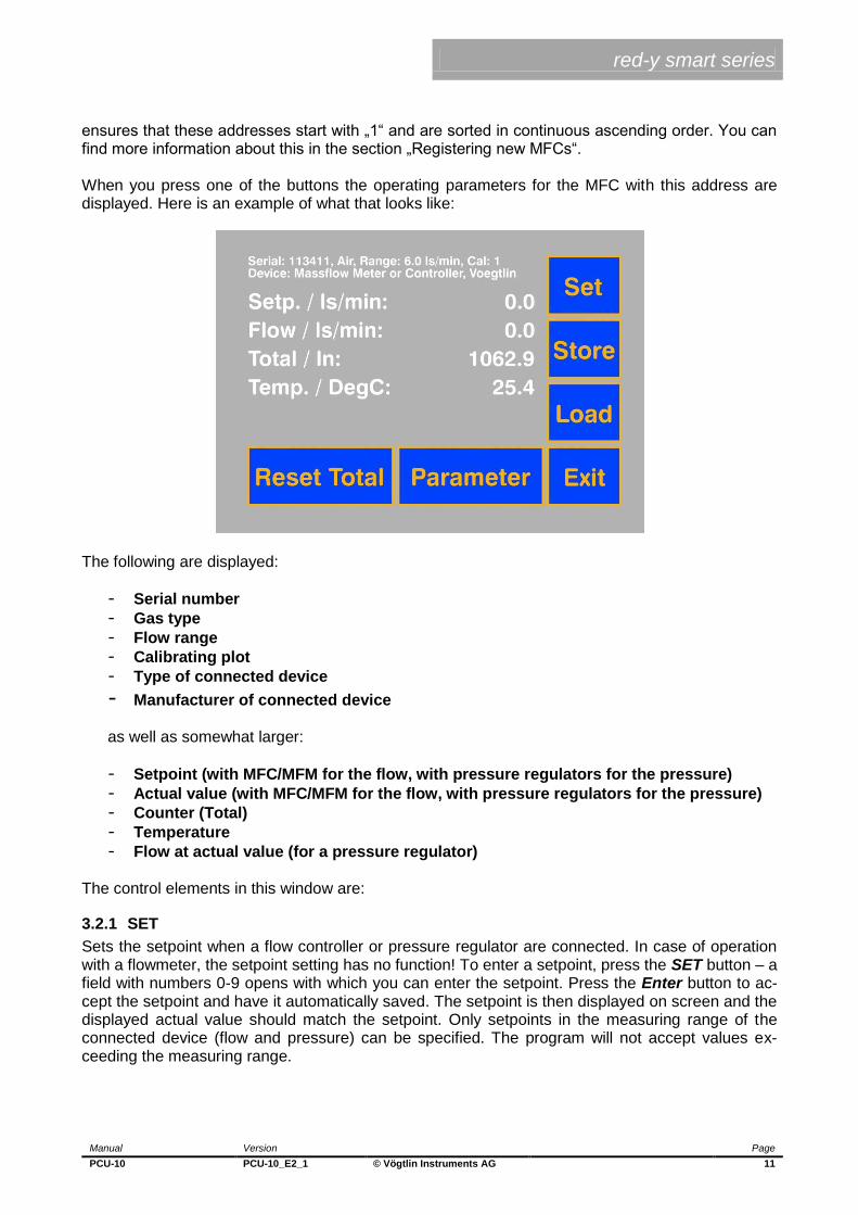
When you press one of the buttons the operating parameters for the MFC with this address are displayed. Here is an example of what that looks like:
The following are displayed:
- Serial number
- Gas type
- Flow range
- Calibrating plot
- Type of connected device
- Manufacturer of connected device as well as somewhat larger:
- Setpoint (with MFC/MFM for the flow, with pressure regulators for the pressure)
- Actual value (with MFC/MFM for the flow, with pressure regulators for the pressure)
- Counter (Total)
- Temperature
- Flow at actual value (for a pressure regulator) The control elements in this window are:
3.2.1 SET
Sets the setpoint when a flow controller or pressure regulator are connected. In case of operation with a flowmeter, the setpoint setting has no function! To enter a setpoint, press the SET button – a field with numbers 0-9 opens with which you can enter the setpoint. Press the Enter button to ac-cept the setpoint and have it automatically saved. The setpoint is then displayed on screen and the displayed actual value should match the setpoint. Only setpoints in the measuring range of the connected device (flow and pressure) can be specified. The program will not accept values ex-ceeding the measuring range.

red-y smart series
Manual Version Page
PCU-10 PCU-10_E2_1 © Vögtlin Instruments AG 12
3.2.2 STORE
Storage function for setpoints (max. 12) – the Store setting has no function in the case of operation with a flowmeter. To save a setpoint, press the Store button – a window opens with the buttons „M1“ through „M12“. „M“ stands for memory, that is, memory location. Pressing one of these but-tons saves the currently set setpoint in memory locations 1-12. The „Exit“ button allows you to return to the previous screen without saving.
3.2.3 LOAD
Loads stored setpoints, thus the counterpart to Store. Setpoints which have been saved via the Store function can be loaded again from this menu. Here again the „Exit“ button lets you return to the previous screen without performing a load.
3.2.4 EXIT
When you exit this window you return to the main screen
3.2.5 RESET TOTAL
Resets the counter/totalizer, which can be found directly on the flowmeter / regulator (real value). When you select this and any other function which represents a permanent intervention in the sys-tem an „Are you sure? “ prompt appears. You must answer with „Yes“ to have the action carried out.
3.2.6 PARAMETER
Menu for setting user parameters – WARNING: Settings should only be made by trained person-nel!
Alarm min. Flow / Alarm max. Flow
Depending on the design of the device the actual value of the flow in the event of exceeding or falling below the set limits appears in RED (or if a 24 volt circuit module is connected a switching contact is switched)

red-y smart series
Manual Version Page
PCU-10 PCU-10_E2_1 © Vögtlin Instruments AG 13
Alarm min. Press / Alarm max. Press
Depending on the design of the device the actual value of the pressure in the event of exceeding or falling below the set limits appears in RED (or if a 24 volt circuit module is connected a switching contact is switched)
CAL
Menu for selection of the factory calibrating plots stored on the device. Selecting the calibrating plot changes the display of the gas type, range and the calibrating plot in the main menu. Warning: possibly set alarm limits must be adapted.
Device
The default setting is „1“ for MFCs and MFMs. In case of a VÖGTLIN pressure regulator the follow-ing settings are possible:
- 1 = Operation of the pressure regulator as a normal MFC/MFM
- 2 = Operation of the pressure regulator as an initial pressure regulator
- 3 = Operation of the pressure regulator as a post pressure regulator MFC, MFM and pressure regulators can be randomly combined with one another in a system. One special feature of the PCU-10 is that, in addition to VÖGTLIN devices it also supports digital MFC from BRONKHORST, which likewise can be randomly combined with other devices. The BRON-HORST devices must be equipped with the „MODBUS“ option.
More
Another menu opens here which shows some properties that are of importance for the general gas mixer function. If you do not use the gas mixer function these parameters are irrelevant.
The parameters in this menu have the following meanings:
Conc In
Gas mixers do not always work with pure gases, under certain circumstances they also work with pre-rarefied gases. Therefore, it is important for the gas mixer function to „know“ the initial concen-tration of a gas. For pure gases please enter „100“ and for „Units“ „Vol%“. Otherwise enter the

red-y smart series
Manual Version Page
PCU-10 PCU-10_E2_1 © Vögtlin Instruments AG 14
amount in Vol% of total gas. If you are working with a high pre-rarefication, the amount can also be specified in ppm instead of in Vol %.
Units
Selects Vol % or ppm as the unit for this gas.
Controlled
For gas mixers which consist of N different channels, the concentrations for N-1 channels are freely adjustable. One channel (usually called „control gas“) however must be freely adjustable by the mixer so that it can achieve the desired concentrations in the case of simultaneous specifica-tion of a total volume flow rate. By choosing „Yes“ for „Controlled“ you are indicating that it is this MFC which is to be freely ad-justable. Please keep in mind that for one gas mixer exactly one of the 2 to 4 possible channels must be designated as „Controlled“. Otherwise you will get an error message.

red-y smart series
Manual Version Page
PCU-10 PCU-10_E2_1 © Vögtlin Instruments AG 15
3.2.7 Menu display for MFC-Control
When you choose the Menu button in the MFC-Control operating mode the following screen dis-plays:
The buttons have the following meanings:
Rescan
Tests whether all registered devices are really connected and deletes devices that are not present from the main screen.
Search
If several devices with different addresses are connected, they are provided with addresses with the numbers 1 and above in ascending order and then displayed by the controller on the main screen.
All 247
All connected devices will be reset to the default address 247 (factory setting).
Load All
The setpoint from memory locations 1 – 12 can be simultaneously loaded for all connected devic-es.
OP Mode
Basic operating mode of the controller
0 = Offline
1 = MFC-Control
2 = Master-Slave mixer
3 = General Gas mixer
4 = Burner controller

red-y smart series
Manual Version Page
PCU-10 PCU-10_E2_1 © Vögtlin Instruments AG 16
Additional analogue Input
The control board of the PCU-10 has an A/D converter, with which the currents in the range 0/4- 20 mA with high resolution (22 bit) can be measured. In the “MFC-Control” operating mode any parameter can be measured and also displayed. In the operating mode “gas mixer” the total flow can be made dependent on the measured values of this input so that O2 controlled mixers and pressure-controlled mixers can be realized. The properties of this input are set here.
Active
„1“ means switched on and „0“ means switched off.

red-y smart series
Manual Version Page
PCU-10 PCU-10_E2_1 © Vögtlin Instruments AG 17
Name
The name to be used for the measured value. A complete alpha-numeric keyboard is available for input which allows you to switch back and forth between Upper Case/Lower Case and Special Characters.
Units
The unit for the measured value, is also set using the keyboard shown above.
Format
The number format with which the measured value is displayed. The format string is borrowed from the programming language C.

red-y smart series
Manual Version Page
PCU-10 PCU-10_E2_1 © Vögtlin Instruments AG 18
Low
This is the measured value which belongs to the lower calibration value.
High
This is the measured value which belongs to the upper calibration value.
Filter
This is the value of a low-pass filter generated by software and indicates the T66 time in seconds.
Cal
Calibration of the input. Since this is an operation which should not be carried out by mistake, a numeric password must first be entered on a numeric keypad.
The password is „314159“, these are the first 6 digits of the Archimedes’ constant, Pi and are therefore easy to remember. Conclude your input by pressing „Enter“.

red-y smart series
Manual Version Page
PCU-10 PCU-10_E2_1 © Vögtlin Instruments AG 19
A window opens in which you can then calibrate the input.
Here are the settings
Low
Accept the current value of the A/D converter displayed in the upper left corner as the low calibra-tion value.
High
Accept the currently displayed value of the A/D converter as the high calibration value.
Reset
Resets the low and high calibration values to the default settings. These are „0.4“ corresponding to 4 mA input current and „2.0“ corresponding to 20 mA input current.
Exit
Exits the menu
Brightness
Sets the brightness of the display.
Exit
Exits the menu

red-y smart series
Manual Version Page
PCU-10 PCU-10_E2_1 © Vögtlin Instruments AG 20
3.3 Main screen for Master-Slave The ‚Master-Slave“ operating mode combines two devices with sequential addresses into a so-called Master-Slave mixer. Here, the odd addresses are equipped with MFMs and the even ad-dresses are equipped with MFCs. It is the task of the Master-Slave mixer to measure the flow of the MFM and to adjust the flow of the MFC in such a way that the mixing ratio remains constant regardless of the quantity that has been discharged. Since, as a result of the fact that MFM and MFC have differing measuring ranges, the mixing ratio can have a very great dynamic range, in the case of the Master-Slave mixer it is possible to specify the mixing ratio both in the unit % as well as in the unit ppm. You can recognize the main screen of this operating mode by the fact that each Pair of this type is labeled with the letters „MS“ as well as with an ascending number starting with „1“.
When you press one of these buttons the display changes to

red-y smart series
Manual Version Page
PCU-10 PCU-10_E2_1 © Vögtlin Instruments AG 21
The following are displayed:
- Serial number of MFM and MFC
- Gas type of MFM and MFC
- Flow range of MFM and MFC
- Calibrating plot of MFM and MFC as well as somewhat larger:
- Setpoint of the mixing ratio
- Actual value for MFM and MFC
- Total volume flow rate of MFM and MFC
- Total calculated from the individual totals of MFM and MFC The control elements in this window are:
3.3.1 SET
Sets the setpoint for the mixing ratio. To enter a setpoint, press the SET button – a field with num-bers 0-9 opens with which you can enter the setpoint. Please keep in mind that there is no Enter button here. Instead, you will see a „%“ button and a „ppm“ button. You conclude your input with one of these unit buttons. After you have pressed the units button the setpoint with the unit is ac-cepted and automatically saved.
3.3.2 STORE
Storage function for setpoints (max. 12). To save a setpoint for the mixing ratio, press the Store button – a window opens with buttons „M1“ through „M12“. „M“ stands for memory, that is, memory location. Press one of the buttons to store the currently set setpoint (of the mixing ratio!) in memory locations 1-12. The „Exit“ button allows you to return to the previous screen without sav-ing.
3.3.3 LOAD
Loads stored setpoints, thus the counterpart to Store. Setpoints which have been saved via the Store function can be loaded again from this menu. Here again the „Exit“ button lets you return to the previous screen without performing a load.EXIT
When you exit this window you return to the main screen
3.3.5 RESET TOTAL
Resets the counter/totalizer, which is located directly on the flowmeter and the regulator (real val-ue). When you select this and any other function which represents a permanent intervention in the system an „Are you sure? “ prompt appears. You must answer with „Yes“ to have the action carried out.
3.3.6 PARAMETER
Menu for setting user parameters – WARNING: Settings should only be made by trained person-nel!

red-y smart series
Manual Version Page
PCU-10 PCU-10_E2_1 © Vögtlin Instruments AG 22
Min Flow 1
The actual value of flow 1 appears in RED if it falls below the set limits (or if a 24 volt circuit module is connected a switching contact is switched)
Max Flow 1
The actual value of flow 1 appears in ROT if it exceeds the set limits (or if a 24 volt circuit module is connected a switching contact is switched)
Min Flow 2
The actual value of flow 2 appears in RED if it falls below the set limits (or if a 24 volt circuit module is connected a switching contact is switched)
Max Flow 2
The actual value of flow 2 appears in ROT if it exceeds the set limits (or if a 24 volt circuit module is connected a switching contact is switched)
Menu display for Master-Slave
The menu in the Master-Slave operating mode looks like this:
The buttons have the following meanings:
Load All
For all mixers, the setpoint of the mixing ratio can be loaded simultaneously from memory locations 1 - 12.
OP Mode
Basic operating mode of the controller
0 = Offline 1 = MFC-Control 2 = Master-Slave mixer 3 = General Gas mixer 4 = Burner controller
red-y smart series
Manual Version Page
PCU-10 PCU-10_E2_1 © Vögtlin Instruments AG 23
Brightness
Sets the brightness of the display.
Exit
Exits the menu

red-y smart series
Manual Version Page
PCU-10 PCU-10_E2_1 © Vögtlin Instruments AG 24
3.4 Main screen of the Mixer function The Mixer function implements a general gas mixer function, in which case two to four MFCs are combined into one mixer.
The names of the gases (automatically read out from the MFCs) appear underneath the column headings as well as the setpoints and PVs (process value) for the 2-4 MFCs, which form the mixer. Currently three mixer types are implemented:
Mixer with fixed adjustable total volume flow rate and adjustable concentrations
Mixer with adjustable concentrations but total volume flow rate automatically resulting from a measured O2 concentration
Mixer with adjustable concentrations but total volume flow rate automatically resulting in dependency on a measured pressure in a buffer container
The first type is intended for general gas mixer functions, while the second is predominantly used in the packaging industry (keyword MAP) and the third type is used when there is a timed with-drawal of mixed gas from a storage tank.

red-y smart series
Manual Version Page
PCU-10 PCU-10_E2_1 © Vögtlin Instruments AG 25
3.4.1 Parameter Window of the Mixer function
When the gas mixer function is selected, the first 2 - 4 registered MFCs (see: Registration of MFCs) are combined into one mixer. The upper 2-4 buttons on the left side of the window display the gas names that have been read out of the MFCs. The units result from the MFC configuration in accordance with 3.2.6.5. For those MFCs not designated as „Controlled“ it is possible to enter the concentration. The value of the MFC designated as „Controlled“ automatically results from the marginal conditions.
Reset All
The values of all adjustable concentrations are set to „0“
On
The mixer is switched on, the currently actual volume flow rate is flowing.
Off
The mixer is switched off, no gas is flowing

red-y smart series
Manual Version Page
PCU-10 PCU-10_E2_1 © Vögtlin Instruments AG 26
More
A second window for the parameterization of the Mixer function opens.
Mixer Type
Here you can select which of the three mixer types is activated. The numbers mean the following
- 1 = Standard Mixer function
- 2 = O2-controlled Mixer
- 3 = Pressure Controlled Mixer The window has a different appearance depending upon which mixer type is selected. In the case of the Standard Mixer function you can only set the Total volume flow rate as second parameter, as shown above.
Total Flow
The Total volume flow rate for the Standard Mixer function in l/Min
Exit
Exits the menu

red-y smart series
Manual Version Page
PCU-10 PCU-10_E2_1 © Vögtlin Instruments AG 27
If an O2-controlled mixer is selected, the window will look like the one shown below.
Here are the settings
Mixer Type
Here you can select which of the three mixer types is activated. The numbers mean the following
- 1 = Standard Mixer function
- 2 = O2-controlled Mixer
- 3 = Pressure Controlled Mixer
Min Total Flow
The total volume flow rate of the mixer in l/Min, which under no circumstances will be fallen short of.
Max Total Flow
The total volume flow rate of the mixer in l/Min, which under no circumstances will be exceeded.
Pos Slope
If the O2-limit measured value is exceeded, the total volume flow rate will be increased every se-cond by the value specified here, until the condition is no longer given.

red-y smart series
Manual Version Page
PCU-10 PCU-10_E2_1 © Vögtlin Instruments AG 28
Neg Slope
If the O2-limit measured value is fallen short of, the total volume flow rate will be decreased every second by the value specified here, until the condition is no longer given.
O2-Limit
Limit of the O2-measurement If a Pressure Controlled Mixer is activated, the second parameter window will have the following appearance:
Here are the settings
Mixer Type
Here you can select which of the three mixer types is activated. The numbers mean the following
- 1 = Standard Mixer function
- 2 = O2-controlled Mixer
- 3 = Pressure Controlled Mixer
Min Total Flow
The total volume flow rate of the mixer in l/Min, which under no circumstances will be fallen short of.

red-y smart series
Manual Version Page
PCU-10 PCU-10_E2_1 © Vögtlin Instruments AG 29
Max Total Flow
The total volume flow rate of the mixer in l/Min, which under no circumstances will be exceeded.
Pressure Low
This is the lower value of the pressure hysteresis. When this value is fallen short of, it results in the mixture generation being switched on with the total volume flow rate Max Total Flow.
Pressure High
This is the upper value of the pressure hysteresis. When this value is exceeded, it results in the mixture generation being switched off. The total volume flow rate has at this time reached the val-ue Min Total Flow.
Exit
Exits the menu
3.4.2 Error Messages of the Mixing Function
The mixing function automatically monitors whether the user input for Total volume flow rate and
the individual concentrations are compatible with the properties of the MFCs with regard to meas-
uring range and dynamics.
If this is not the case, one of the error messages listed below will be displayed:
"Violation of MFC 1 minimum value" "Violation of MFC 1 maximum value" "Not enough flow free for MFC 1" "Violation of MFC 2 minimum value" "Violation of MFC 2 maximum value" "Not enough flow free for MFC 2" "Violation of MFC 3 minimum value" "Violation of MFC 3 maximum value" "Not enough flow free for MFC 3" "Violation of MFC 4 minimum value" "Violation of MFC 4 maximum value" "Not enough flow free for MFC 4" "Violation of MFC 1 minimum value at lower total flow value" "Violation of MFC 1 maximum value at lower total flow value" "Not enough flow free for MFC 1 at lower total flow value" "Violation of MFC 2 minimum value at lower total flow value" "Violation of MFC 2 maximum value at lower total flow value" "Not enough flow free for MFC 2 at lower total flow value" "Violation of MFC 3 minimum value at lower total flow value" "Violation of MFC 3 maximum value at lower total flow value" "Not enough flow free for MFC 3 at lower total flow value" "Violation of MFC 4 minimum value at lower total flow value" "Violation of MFC 4 maximum value at lower total flow value" "Not enough flow free for MFC 4 at lower total flow value" "Violation of MFC 1 minimum value at higher total flow value" "Violation of MFC 1 maximum value at higher total flow value"

red-y smart series
Manual Version Page
PCU-10 PCU-10_E2_1 © Vögtlin Instruments AG 30
"Not enough flow free for MFC 1 at higher total flow value" "Violation of MFC 2 minimum value at higher total flow value" "Violation of MFC 2 maximum value at higher total flow value" "Not enough flow free for MFC 2 at higher total flow value" "Violation of MFC 3 minimum value at higher total flow value" "Violation of MFC 3 maximum value at higher total flow value" "Not enough flow free for MFC 3 at higher total flow value" "Violation of MFC 4 minimum value at higher total flow value" "Violation of MFC 4 maximum value at higher total flow value" "Not enough flow free for MFC 4 at higher total flow value" In such cases you will have to modify your operating parameters accordingly.

red-y smart series
Manual Version Page
PCU-10 PCU-10_E2_1 © Vögtlin Instruments AG 31
3.5 Main Screen of the Burner Controller
The Burner Controller is used for the controlled ignition of an oven and its monitoring after ignition.
First both MFCs and both solenoid valves are closed. The actual values of both MFCs are dis-
played in the bottom left corner of the screen.
In the case of the Burner Controller a series connection of four zero potential contacts is moni-
tored, consisting of two pressure monitors arranged upstream of the MFCs, one emergency off
switch and a fourth contact supplied by a monitoring camera which detects a flame in the oven.
Please keep in mind that the series connection will only signal a „good state“ when all the contacts
are closed. Opening a single contact is sufficient to set the „bad state“.
We will assume that both pressures are okay and that the emergency off switch has not been
pressed. Then the good/bad state will only be set by the contact of the camera.

red-y smart series
Manual Version Page
PCU-10 PCU-10_E2_1 © Vögtlin Instruments AG 32
The big „Start Oven“ button opens both solenoid valves and sets both MFCs to a specified set-
point. This setpoint is the one which arises from the parameterization of the burner control-
ler for the ignition.
The resulting gas mixture is used to ignite the oven. In this phase the screen looks like the one
shown above (in reality the MFCs display different numbers than „0“):
After the oven is started a seconds counter runs backwards from 16 to 0. If no flame has been de-
tected during this time, the solenoid valves are closed, the setpoints of the MFCs are set to „0“ and
an error message appears on the screen which must be confirmed by the user before a new igni-
tion can be initiated.
If the monitoring camera detected a flame within this time, the original mixing ratio remains con-
stant, but the display changes to

red-y smart series
Manual Version Page
PCU-10 PCU-10_E2_1 © Vögtlin Instruments AG 33
With this the Burner Controller is informing the user that everything is okay and that you can switch
to the second gas mixture by pressing the button. The second gas mixture is the one which
results from the parameterization of the burner controller for the full load range. After shifting
to the second mixture the display changes to:
Now the oven can be switched off at any time by pressing the Stop button. It will likewise be imme-
diately switched off if the system detects a bad condition.
Keep in mind that during the ignition phase of the system, that is, if „Full Load“ is displayed, a bad
condition is allowed to occur without resulting in the system being immediately switched off. If a
bad condition occurs in this state, the „Waiting for Ignition“ display appears and the timer will be
restarted and run backwards. In this phase an abortion of the gasing is exclusively triggered by the
expiration of the timer, which can be retriggered.

red-y smart series
Manual Version Page
PCU-10 PCU-10_E2_1 © Vögtlin Instruments AG 34
3.5.1 Parameters of the Burner Controller
Pressing the „Para“ button takes you to the parameter settings of the Burner Controller.
MFC % Tot @ Ignition
MFC1 is responsible for the fuel gas, MFC2 for the oxygen carrier. This setting defines how high
the percentage of fuel gas in the total gas flow for the ignition flame is.
Total Flow @ Ignition
This setting defines how high the total gas flow is in l/Min for the ignition flame.
MFC % Tot @ full Load
This setting defines how high the percentage of combustible gas is in the total gas flow for a full
load operation.
Total Flow @ full Load
This setting defines how great the total gas flow in l/Min for the full load operation.
Store Nonvolatile
When this button is pressed the visible settings are saved in non-volatile memory.
Exit
Exits the window

red-y smart series
Manual Version Page
PCU-10 PCU-10_E2_1 © Vögtlin Instruments AG 35
3.5.2 Menu Display of the Burner Controller
The menu of the Burner controller is shown in the figure above. The buttons have the following
meanings:
OP Mode
Basic operating mode of the controller
0 = Offline 1 = MFC-Control 2 = Master-Slave mixer 3 = General Gas mixer 4 = Burner controller
Brightness
Sets the brightness of the display.
Exit
Exits the menu
Please keep in mind that the menu button of the Burner Controller is only visible in the idle state of
the system, that is, when the oven has been switched off. This ensures that the operating mode
cannot be changed when the oven is burning and thus the oven cannot achieve an undefined
state.
3.5.3 Error Messages of the Burner Controller
The Burner Controller automatically monitors whether the user input for Total volume flow rate and
the combustible gas percentage are compatible with the properties of the MFC with regard to
measuring range and dynamics.
If this is not the case, one of the error messages listed below will be displayed:

red-y smart series
Manual Version Page
PCU-10 PCU-10_E2_1 © Vögtlin Instruments AG 36
"MFC1 setpoint < 3% range @ ignition"
"MFC1 setpoint > range @ ignition"
"MFC2 setpoint < 3% range @ ignition"
"MFC2 setpoint > range @ ignition"
"MFC1 setpoint < 3% range @ full Load"
"MFC1 setpoint > range @ full Load"
"MFC2 setpoint < 3% range @ full Load"
"MFC2 setpoint > range @ full Load"
In such cases you will have to modify your operating parameters accordingly.

red-y smart series
Manual Version Page
PCU-10 PCU-10_E2_1 © Vögtlin Instruments AG 37
4 Registering new MFCs The registration of new MFCs to the controller is only possible in MFC control mode.
The device has an internal memory with which it can administer 23 VÖGTLIN or BRONKHORST
MFCs. The adding or registration of new MFCs to this memory takes place by having an MFC with
the MODBUS address 247 in switched off state (delivery state) connected to the device in addi-
tion to the MFCs that are already registered and switching the device on afterwards.
A screen then appears, with a separate touch button displayed for every registered MFC. You can
use the buttons to make settings for the relevant MFC.
Even if an MFC is electrically separated from the device, its associated button will be preserved at
first. You may plug this MFC back in again. If you press the button of an MFC that is not available,
the message „Not available“ appears on the screen for two seconds, followed by the normal dis-
play.
To permanently remove an MFC from the system, press the „Menu“ button and then press the
„Rescan“ button. During the scanning all registered MFCs are then tested to determine whether
they are present. Those that are not detected are removed from the list. After that any resulting
gaps in the consecutive numbering are filled by „pushing“ numbers from the rear to the front so that
there is always a consecutive numbering on the display.
As you can see, registering new MFCs requires their being set to MODBUS address 247. Since
one cannot always know for certain, the device offers the possibility of forcing all connected
MFCs to be set to address 247 via the button sequence „Menu“ and „All 247“. Once you have done
this with several connected MFCs, you would then electrically separate all the MFCs from the de-
vice (please, also in switched off state) and after that register the MFCs one after the other by
repeating the following operation
- Switch off - Plug in the next MFC - Switch on
Since both the scanning and the setting of the address constitute serious interventions in the sys-
tem, these functions are also followed by an „Are you sure?“ prompt.
For the function „Master-Slave“ you need to keep in mind that for a Master-Slave mixer there must
always be one MFM at an odd address and one MFC at an even address.
MFCs with addresses 1 and 2 are used for the „Burner controller“ function.

red-y smart series
Manual Version Page
PCU-10 PCU-10_E2_1 © Vögtlin Instruments AG 38
If you register a device from BRONKHORST, make certain that the lateral rotary switches for the
MODBUS address are at „00“. This is the only way PCU-10 can dynamically change the address of
the device.

red-y smart series
Manual Version Page
PCU-10 PCU-10_E2_1 © Vögtlin Instruments AG 39
5 Repair Instructions Repairs can only be made after prior consultation with the manufacturer. All warranties expire in
the case of unauthorized repairs, add-ons or retrofitting.
6 Installation Guide for Panel Mount Version
View from the front on the touch screen from operator side. All dimensions are mm.
Caution: the ribbon cable must be placed as indicated.
Front ribbon cable opening
Top

red-y smart series
Manual Version Page
PCU-10 PCU-10_E2_1 © Vögtlin Instruments AG 40
Dimensions of the front cut out including 4 drillings:
The four pre installed distance pins are planned for a front wall thickness of 2 mm und should be
adjusted to the actual wall thickness.
Front and side view:
Oben

red-y smart series
Manual Version Page
PCU-10 PCU-10_E2_1 © Vögtlin Instruments AG 41
Connector sockets on the display pcb:
J1: 24 Volt connector, the included black and red cable adapter (black - / red +) is pre configured
and has to be connected to the included power supply V- and V+.
Make sure a proper grounding of the power supply is given.
J2: Analog input for a external signal: 1:+24 Volt, 2: + Signal, 3: - Signal
P1: this socket is for software updates operated by service personnel only.
P6, P7, P8 – connector for RS485 Modbus to MFC. All three sockets can be used for the Modbus
network. According to the 3,2 A output of the power supply max. 10 MFCs can be hooked to one
PCU-10.
P6, P7, P8 connector for RS485 for
MFC 24 volt connector
J2: analog input: 1,2,3
red-y smart series
Manual Version Page
PCU-10 PCU-10_E2_1 © Vögtlin Instruments AG 42
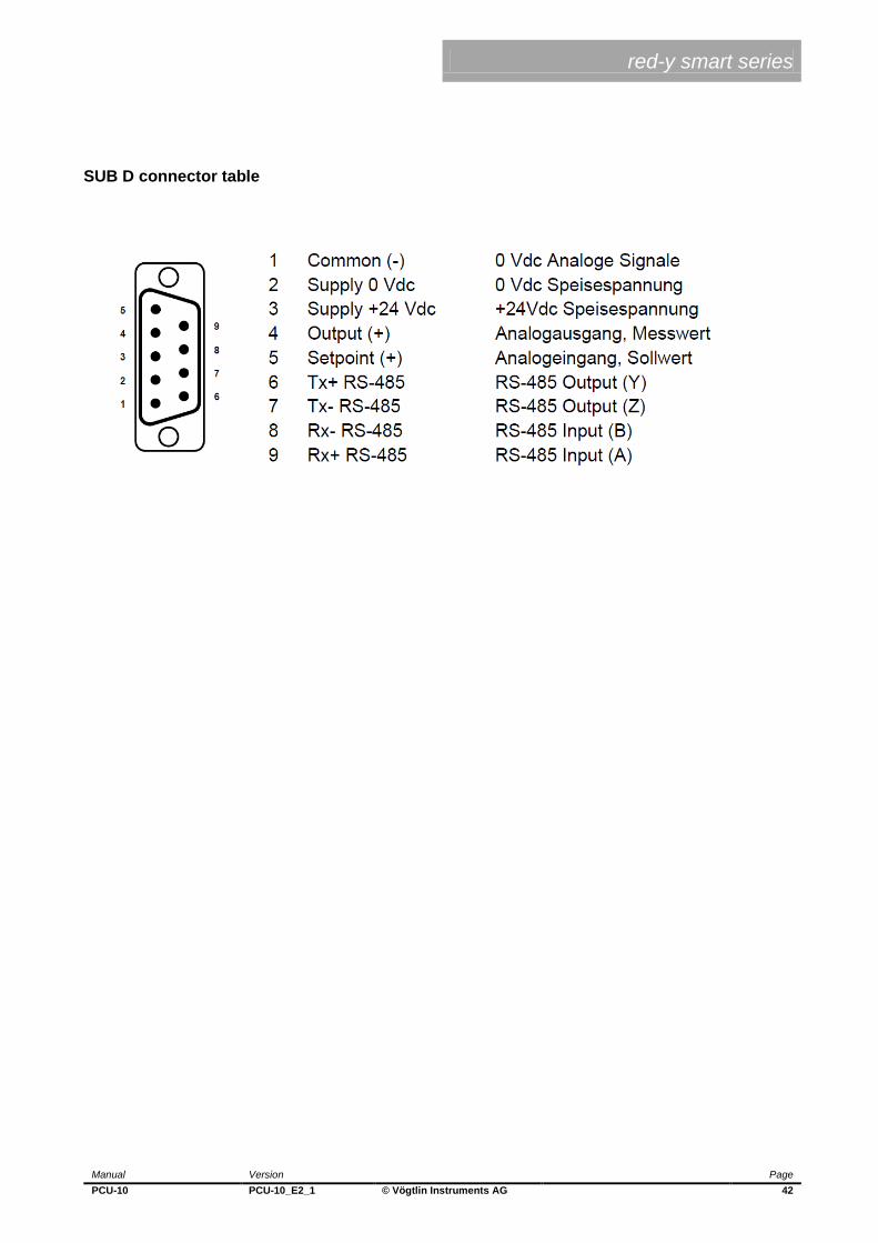
SUB D connector table