![Optimization. I. Textbook Examples How did we know that the domain of A is [0,100]](https://static.fdocuments.us/doc/165x107/5a4d1ae17f8b9ab059977235/optimization-i-textbook-examples-how-did-we-know-that-the-domain-of-a-is.jpg)
Optimization. I. Textbook Examples How did we know that the domain of A is [0,100]
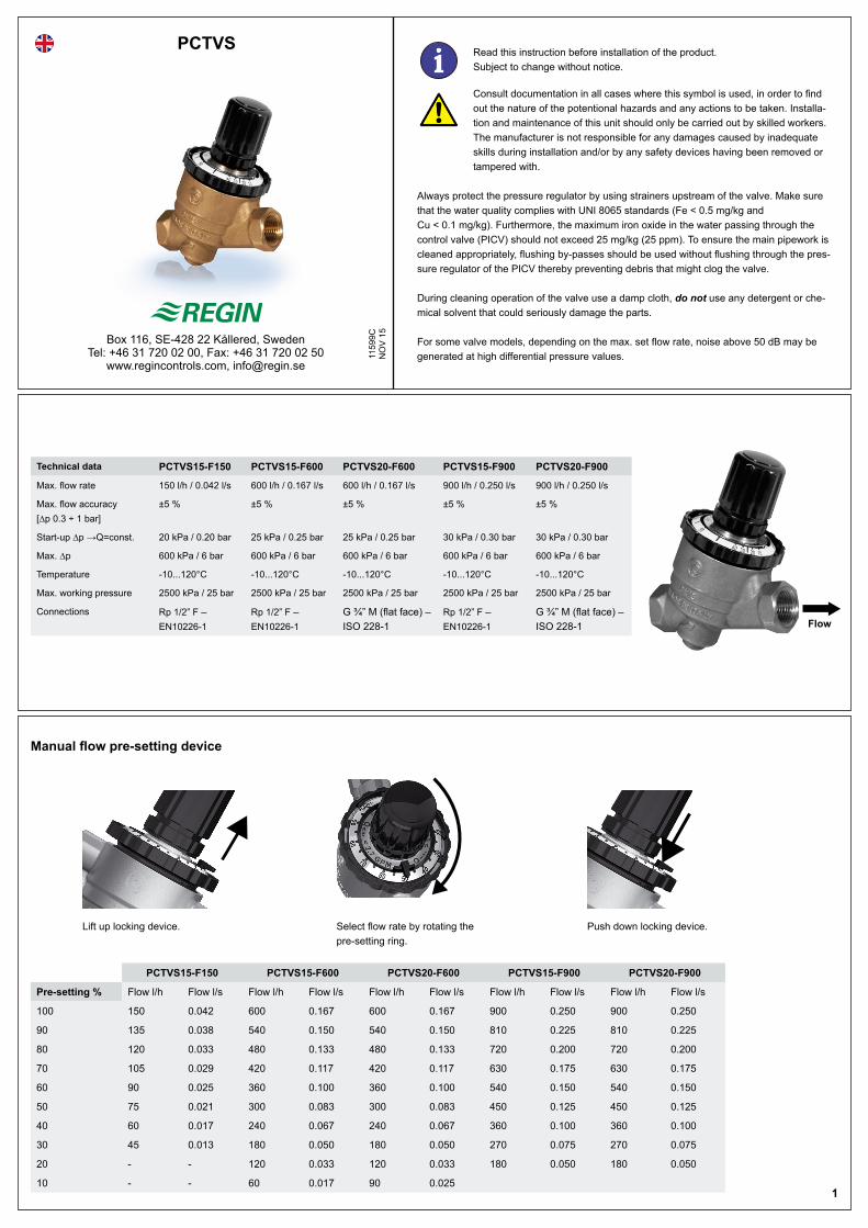
PCTVS
1159
9CN
OV
15Box 116, SE-428 22 Kållered, Sweden Tel: +46 31 720 02 00, Fax: +46 31 720 02 50
www.regincontrols.com, [email protected]
Lift up locking device. Select flow rate by rotating the pre-setting ring.
Push down locking device.
Flow
Manual flow pre-setting device
1
Technical data PCTVS15-F150 PCTVS15-F600 PCTVS20-F600 PCTVS15-F900 PCTVS20-F900
Max. flow rate 150 l/h / 0.042 l/s 600 l/h / 0.167 l/s 600 l/h / 0.167 l/s 900 l/h / 0.250 l/s 900 l/h / 0.250 l/s
Max. flow accuracy [∆p 0.3 ÷ 1 bar]
±5 % ±5 % ±5 % ±5 % ±5 %
Start-up ∆p →Q=const. 20 kPa / 0.20 bar 25 kPa / 0.25 bar 25 kPa / 0.25 bar 30 kPa / 0.30 bar 30 kPa / 0.30 bar
Max. ∆p 600 kPa / 6 bar 600 kPa / 6 bar 600 kPa / 6 bar 600 kPa / 6 bar 600 kPa / 6 bar
Temperature -10...120°C -10...120°C -10...120°C -10...120°C -10...120°C
Max. working pressure 2500 kPa / 25 bar 2500 kPa / 25 bar 2500 kPa / 25 bar 2500 kPa / 25 bar 2500 kPa / 25 bar
Connections Rp 1/2” F – EN10226-1
Rp 1/2” F – EN10226-1
G ¾” M (flat face) – ISO 228-1
Rp 1/2” F – EN10226-1
G ¾” M (flat face) – ISO 228-1
PCTVS15-F150 PCTVS15-F600 PCTVS20-F600 PCTVS15-F900 PCTVS20-F900
Pre-setting % Flow l/h Flow l/s Flow l/h Flow l/s Flow l/h Flow l/s Flow l/h Flow l/s Flow l/h Flow l/s
100 150 0.042 600 0.167 600 0.167 900 0.250 900 0.250
90 135 0.038 540 0.150 540 0.150 810 0.225 810 0.225
80 120 0.033 480 0.133 480 0.133 720 0.200 720 0.200
70 105 0.029 420 0.117 420 0.117 630 0.175 630 0.175
60 90 0.025 360 0.100 360 0.100 540 0.150 540 0.150
50 75 0.021 300 0.083 300 0.083 450 0.125 450 0.125
40 60 0.017 240 0.067 240 0.067 360 0.100 360 0.100
30 45 0.013 180 0.050 180 0.050 270 0.075 270 0.075
20 - - 120 0.033 120 0.033 180 0.050 180 0.050
10 - - 60 0.017 90 0.025
i Read this instruction before installation of the product. Subject to change without notice.
Consult documentation in all cases where this symbol is used, in order to find out the nature of the potentional hazards and any actions to be taken. Installa-tion and maintenance of this unit should only be carried out by skilled workers. The manufacturer is not responsible for any damages caused by inadequate skills during installation and/or by any safety devices having been removed or tampered with.
Always protect the pressure regulator by using strainers upstream of the valve. Make sure that the water quality complies with UNI 8065 standards (Fe < 0.5 mg/kg and Cu < 0.1 mg/kg). Furthermore, the maximum iron oxide in the water passing through the control valve (PICV) should not exceed 25 mg/kg (25 ppm). To ensure the main pipework is cleaned appropriately, flushing by-passes should be used without flushing through the pres-sure regulator of the PICV thereby preventing debris that might clog the valve.
During cleaning operation of the valve use a damp cloth, do not use any detergent or che-mical solvent that could seriously damage the parts.
For some valve models, depending on the max. set flow rate, noise above 50 dB may be generated at high differential pressure values.
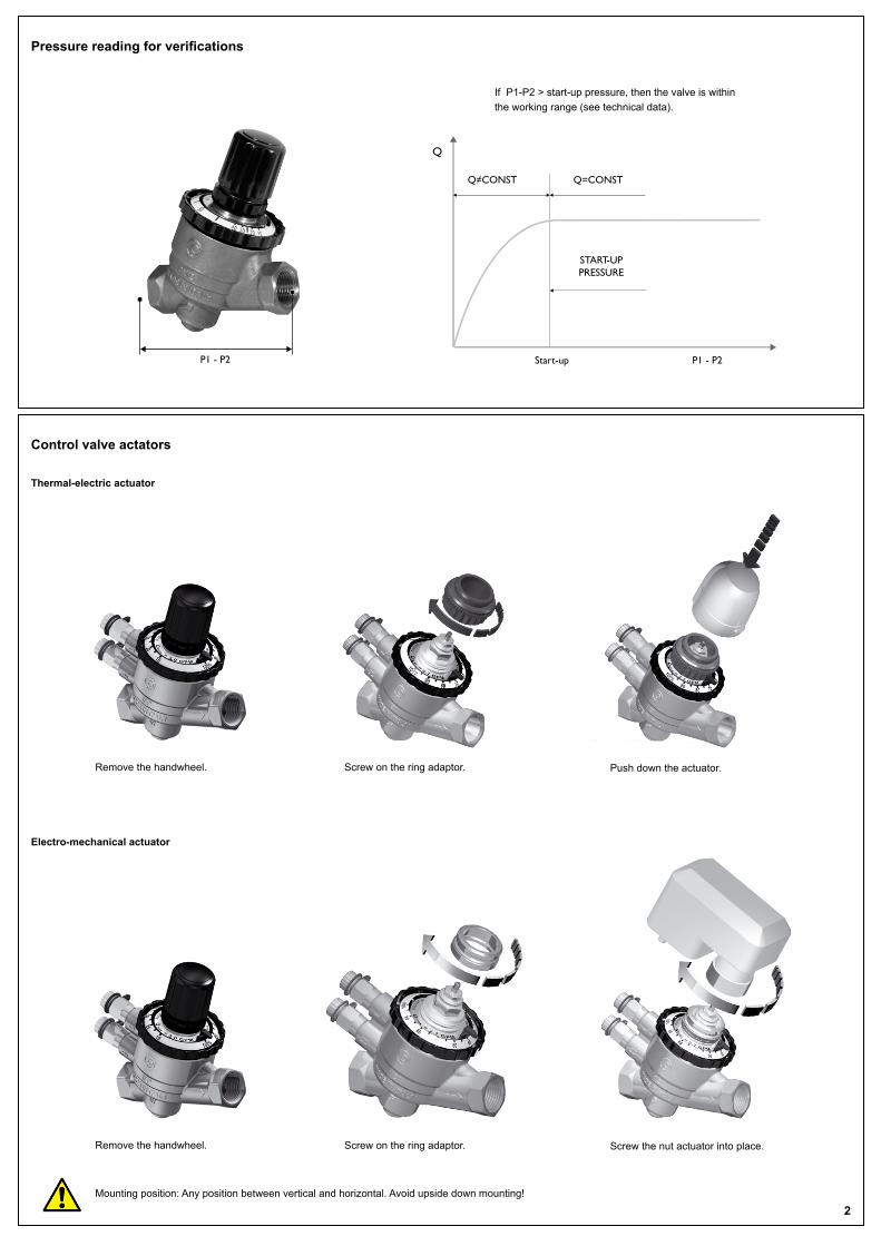
If P1-P2 > start-up pressure, then the valve is within the working range (see technical data).
Electro-mechanical actuator
Remove the handwheel. Screw on the ring adaptor. Screw the nut actuator into place.
Mounting position: Any position between vertical and horizontal. Avoid upside down mounting!
Q≠CONST Q=CONST
Q
P1 - P2
START-UP PRESSURE
P1 - P2 Start-up
Pressure reading for verifications
2
Control valve actators
Thermal-electric actuator
Remove the handwheel. Screw on the ring adaptor. Push down the actuator.
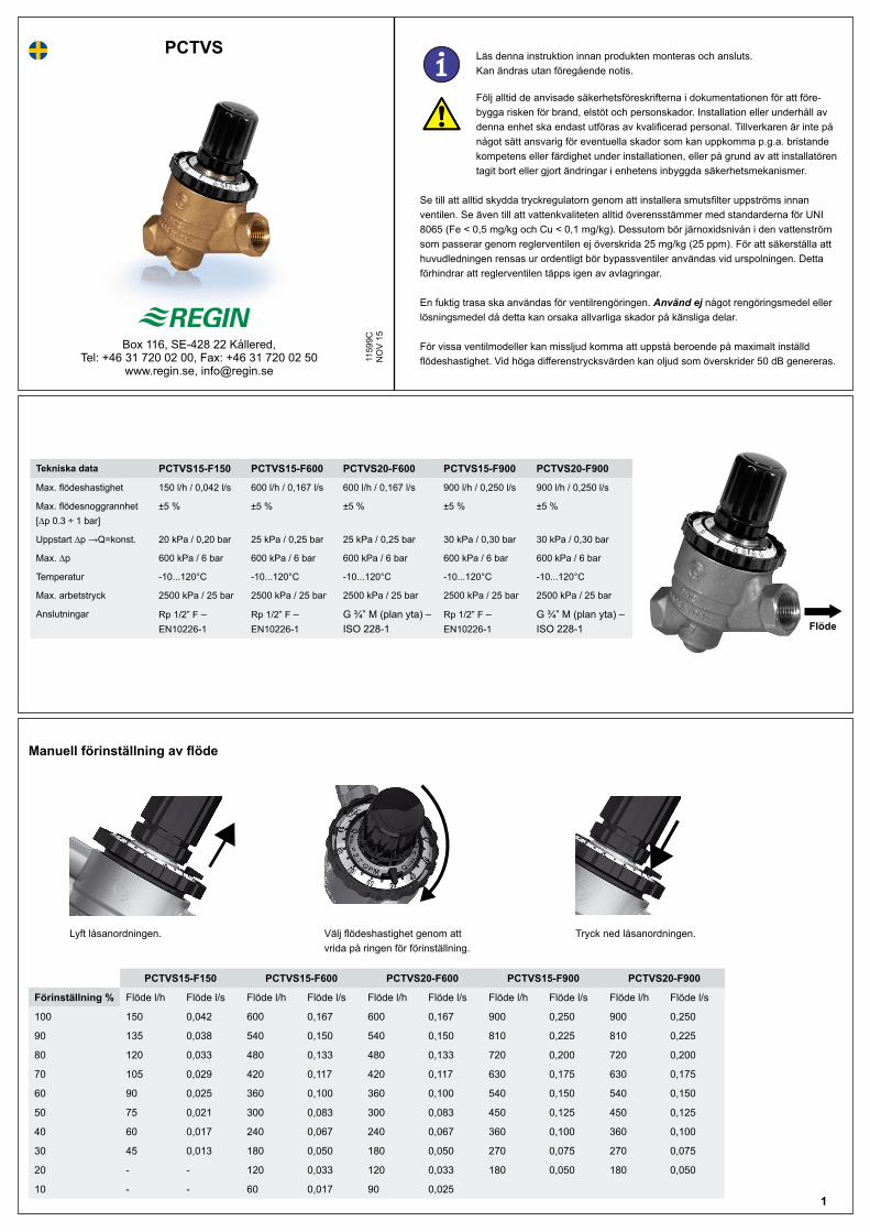
PCTVS
1159
9CN
OV
15Box 116, SE-428 22 Kållered, Tel: +46 31 720 02 00, Fax: +46 31 720 02 50
www.regin.se, [email protected]
Lyft låsanordningen. Välj flödeshastighet genom att vrida på ringen för förinställning.
Tryck ned låsanordningen.
Flöde
Manuell förinställning av flöde
1
Tekniska data PCTVS15-F150 PCTVS15-F600 PCTVS20-F600 PCTVS15-F900 PCTVS20-F900
Max. flödeshastighet 150 l/h / 0,042 l/s 600 l/h / 0,167 l/s 600 l/h / 0,167 l/s 900 l/h / 0,250 l/s 900 l/h / 0,250 l/s
Max. flödesnoggrannhet [∆p 0.3 ÷ 1 bar]
±5 % ±5 % ±5 % ±5 % ±5 %
Uppstart ∆p →Q=konst. 20 kPa / 0,20 bar 25 kPa / 0,25 bar 25 kPa / 0,25 bar 30 kPa / 0,30 bar 30 kPa / 0,30 bar
Max. ∆p 600 kPa / 6 bar 600 kPa / 6 bar 600 kPa / 6 bar 600 kPa / 6 bar 600 kPa / 6 bar
Temperatur -10...120°C -10...120°C -10...120°C -10...120°C -10...120°C
Max. arbetstryck 2500 kPa / 25 bar 2500 kPa / 25 bar 2500 kPa / 25 bar 2500 kPa / 25 bar 2500 kPa / 25 bar
Anslutningar Rp 1/2” F – EN10226-1
Rp 1/2” F – EN10226-1
G ¾” M (plan yta) – ISO 228-1
Rp 1/2” F – EN10226-1
G ¾” M (plan yta) – ISO 228-1
PCTVS15-F150 PCTVS15-F600 PCTVS20-F600 PCTVS15-F900 PCTVS20-F900
Förinställning % Flöde l/h Flöde l/s Flöde l/h Flöde l/s Flöde l/h Flöde l/s Flöde l/h Flöde l/s Flöde l/h Flöde l/s
100 150 0,042 600 0,167 600 0,167 900 0,250 900 0,250
90 135 0,038 540 0,150 540 0,150 810 0,225 810 0,225
80 120 0,033 480 0,133 480 0,133 720 0,200 720 0,200
70 105 0,029 420 0,117 420 0,117 630 0,175 630 0,175
60 90 0,025 360 0,100 360 0,100 540 0,150 540 0,150
50 75 0,021 300 0,083 300 0,083 450 0,125 450 0,125
40 60 0,017 240 0,067 240 0,067 360 0,100 360 0,100
30 45 0,013 180 0,050 180 0,050 270 0,075 270 0,075
20 - - 120 0,033 120 0,033 180 0,050 180 0,050
10 - - 60 0,017 90 0,025
i Läs denna instruktion innan produkten monteras och ansluts. Kan ändras utan föregående notis.
Följ alltid de anvisade säkerhetsföreskrifterna i dokumentationen för att före-bygga risken för brand, elstöt och personskador. Installation eller underhåll av denna enhet ska endast utföras av kvalificerad personal. Tillverkaren är inte på något sätt ansvarig för eventuella skador som kan uppkomma p.g.a. bristande kompetens eller färdighet under installationen, eller på grund av att installatören tagit bort eller gjort ändringar i enhetens inbyggda säkerhetsmekanismer.
Se till att alltid skydda tryckregulatorn genom att installera smutsfilter uppströms innan ventilen. Se även till att vattenkvaliteten alltid överensstämmer med standarderna för UNI 8065 (Fe < 0,5 mg/kg och Cu < 0,1 mg/kg). Dessutom bör järnoxidsnivån i den vattenström som passerar genom reglerventilen ej överskrida 25 mg/kg (25 ppm). För att säkerställa att huvudledningen rensas ur ordentligt bör bypassventiler användas vid urspolningen. Detta förhindrar att reglerventilen täpps igen av avlagringar.
En fuktig trasa ska användas för ventilrengöringen. Använd ej något rengöringsmedel eller lösningsmedel då detta kan orsaka allvarliga skador på känsliga delar.
För vissa ventilmodeller kan missljud komma att uppstå beroende på maximalt inställd flödeshastighet. Vid höga differenstrycksvärden kan oljud som överskrider 50 dB genereras.
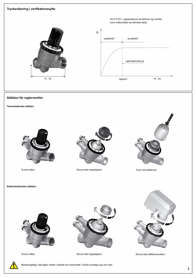
Om P1-P2 > uppstartstryck så befinner sig ventilen inom mätområdet (se tekniska data).
Elektromekaniska ställdon
Ta bort ratten. Skruva fast ringadaptern. Skruva fast ställdonsmuttern.
Monteringsläge: Alla lägen mellan vertikalt och horisontellt. Undvik montage upp och ned!
Q≠KONST Q=KONST
Q
P1 - P2
UPPSTARTSTRYCK
P1 - P2 Uppstart
Tryckavläsning i verifikationssyfte
2
Ställdon för reglerventiler
Termoelektriska ställdon
Ta bort ratten. Skruva fast ringadaptern. Tryck ned ställdonet.
PCTVS
1159
9CN
OV
15Regin Controls Deutschland GmbH Tel: +49 30 77 99 40, Fax: +49 30 77 99 479 www.regincontrols.de, [email protected]
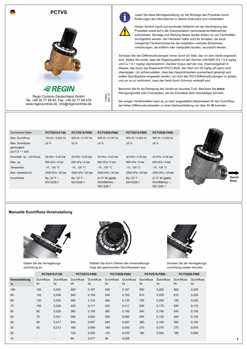
Heben Sie die Verriegelungs-vorrichtung an.
Wählen Sie durch Drehen des Voreinstellungs-rings den gewünschten Durchflusswert aus.
Drücken Sie die Verriegelungs-vorrichtung wieder herunter.
Durch-fluss
Manuelle Durchfluss-Voreinstellung
1
Technische Daten PCTVS15-F150 PCTVS15-F600 PCTVS20-F600 PCTVS15-F900 PCTVS20-F900
Max. Durchfluss 150 l/h / 0,042 l/s 600 l/h / 0,167 l/s 600 l/h / 0,167 l/s 900 l/h / 0,250 l/s 900 l/h / 0,250 l/s
Max. Durchfluss-genauigkeit [∆p 0,3 ÷ 1 bar]
±5 % ±5 % ±5 % ±5 % ±5 %
Einschalt- ∆p →Q=Konst. 20 kPa / 0,20 bar 25 kPa / 0,25 bar 25 kPa / 0,25 bar 30 kPa / 0,30 bar 30 kPa / 0,30 bar
Max. ∆p 600 kPa / 6 bar 600 kPa / 6 bar 600 kPa / 6 bar 600 kPa / 6 bar 600 kPa / 6 bar
Temperatur -10...120 °C -10...120 °C -10...120 °C -10...120 °C -10...120 °C
Max. Arbeitsdruck 2500 kPa / 25 bar 2500 kPa / 25 bar 2500 kPa / 25 bar 2500 kPa / 25 bar 2500 kPa / 25 bar
Anschlüsse Rp 1/2" F – EN10226-1
Rp 1/2" F – EN10226-1
G ¾" M (glatte Dichtfläche) – ISO 228-1
Rp 1/2" F – EN10226-1
G ¾" M (glatte Dichtfläche) – ISO 228-1
PCTVS15-F150 PCTVS15-F600 PCTVS20-F600 PCTVS15-F900 PCTVS20-F900
Voreinstellung %
Durchfluss l/h
Durchfluss l/s
Durchfluss l/h
Durchfluss l/s
Durchfluss l/h
Durchfluss l/s
Durchfluss l/h
Durchfluss l/s
Durchfluss l/h
Durchfluss l/s
100 150 0,042 600 0,167 600 0,167 900 0,250 900 0,250
90 135 0,038 540 0,150 540 0,150 810 0,225 810 0,225
80 120 0,033 480 0,133 480 0,133 720 0,200 720 0,200
70 105 0,029 420 0,117 420 0,117 630 0,175 630 0,175
60 90 0,025 360 0,100 360 0,100 540 0,150 540 0,150
50 75 0,021 300 0,083 300 0,083 450 0,125 450 0,125
40 60 0,017 240 0,067 240 0,067 360 0,100 360 0,100
30 45 0,013 180 0,050 180 0,050 270 0,075 270 0,075
20 - - 120 0,033 120 0,033 180 0,050 180 0,050
10 - - 60 0,017 90 0,025
i Lesen Sie diese Montageanleitung vor der Montage des Produktes durch. Änderungen der Informationen in diesem Dokument sind vorbehalten.
Dieses Symbol macht auf eventuelle Gefahren bei der Handhabung des Produktes sowie auf in der Dokumentation nachzulesende Maßnahmen aufmerksam. Montage und Wartung dieses Geräts dürfen nur von Fachkräften durchgeführt werden. Der Hersteller haftet nicht für Schäden, die durch mangelnde Fachkenntnisse bei der Installation und/oder Sicherheits-vorkehrungen, die entfernt oder manipuliert wurden, verursacht werden.
Schützen Sie den Differenzdruckregler immer durch ein Sieb, das vor dem Ventil eingesetzt wird. Stellen Sie sicher, dass die Wasserqualität mit den Normen UNI 8065 (Fe < 0,5 mg/kg und Cu < 0,1 mg/kg) übereinstimmt. Darüber hinaus darf der max. Eisenoxidgehalt im Wasser, das durch das Regelventil (PICV) fließt, den Wert von 25 mg/kg (25 ppm) nicht übersteigen. Um sicherzustellen, dass das Hauptrohrsystem ausreichend gereinigt wird, sollten Spül-Bypässe eingesetzt werden, um nicht den PICV-Differenzdruckregler zu spülen, und um so zu verhindern, dass das Ventil durch Schmutz verstopft wird.
Benutzen Sie für die Reinigung des Ventils ein feuchtes Tuch. Benutzen Sie keine Reinigungs mittel oder Chemikalien, die die Einzelteile stark beschädigen könnten.
Bei einigen Ventilmodellen kann es, je nach eingestelltem Maximalwert für den Durchfluss, bei hohen Differenzdruckwerten zu einer Geräuschbildung von über 50 dB kommen.
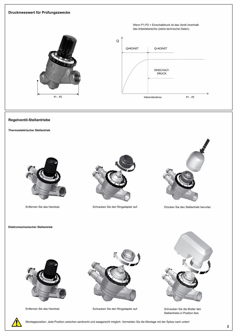
Wenn P1-P2 > Einschaltdruck ist das Ventil innerhalb des Arbeitsbereichs (siehe technische Daten).
Elektromechanischer Stellantrieb
Entfernen Sie das Handrad. Schrauben Sie den Ringadapter auf. Schrauben Sie die Mutter des Stellantriebs in Position fest.
Montageposition: Jede Position zwischen senkrecht und waagerecht möglich. Vermeiden Sie die Montage mit der Spitze nach unten!
Q≠KONST Q=KONST
Q
P1 - P2
EINSCHALT-DRUCK
P1 - P2 Inbetriebnahme
Druckmesswert für Prüfungszwecke
2
Regelventil-Stellantriebe
Thermoelektrischer Stellantrieb
Entfernen Sie das Handrad. Schrauben Sie den Ringadapter auf. Drücken Sie den Stellantrieb herunter.