PCS 7 Basic Library V71 - Siemens
350
General Information About Block Description 1 Family: CONTROL 2 Family: @System 3 Internal block 4 Faceplates and block icons 5 Appendix 6 SIMATIC Process Control System PCS 7 PCS 7 Basic Library V71 Function Manual 03/2009 A5E02102513-01
Transcript of PCS 7 Basic Library V71 - Siemens

General Information About Block Description 1
Family: CONTROL
2
Family: @System
3
Internal block
4
Faceplates and block icons
5
Appendix
6
SIMATIC
Process Control System PCS 7PCS 7 Basic Library V71
Function Manual
03/2009 A5E02102513-01
Legal information Warning notice system
This manual contains notices you have to observe in order to ensure your personal safety, as well as to prevent damage to property. The notices referring to your personal safety are highlighted in the manual by a safety alert symbol, notices referring only to property damage have no safety alert symbol. These notices shown below are graded according to the degree of danger.
DANGER indicates that death or severe personal injury will result if proper precautions are not taken.
WARNING indicates that death or severe personal injury may result if proper precautions are not taken.
CAUTION with a safety alert symbol, indicates that minor personal injury can result if proper precautions are not taken.
CAUTION without a safety alert symbol, indicates that property damage can result if proper precautions are not taken.
NOTICE indicates that an unintended result or situation can occur if the corresponding information is not taken into account.
If more than one degree of danger is present, the warning notice representing the highest degree of danger will be used. A notice warning of injury to persons with a safety alert symbol may also include a warning relating to property damage.
Qualified Personnel The device/system may only be set up and used in conjunction with this documentation. Commissioning and operation of a device/system may only be performed by qualified personnel. Within the context of the safety notes in this documentation qualified persons are defined as persons who are authorized to commission, ground and label devices, systems and circuits in accordance with established safety practices and standards.
Proper use of Siemens products Note the following:
WARNING Siemens products may only be used for the applications described in the catalog and in the relevant technical documentation. If products and components from other manufacturers are used, these must be recommended or approved by Siemens. Proper transport, storage, installation, assembly, commissioning, operation and maintenance are required to ensure that the products operate safely and without any problems. The permissible ambient conditions must be adhered to. The information in the relevant documentation must be observed.
Trademarks All names identified by ® are registered trademarks of the Siemens AG. The remaining trademarks in this publication may be trademarks whose use by third parties for their own purposes could violate the rights of the owner.
Disclaimer of Liability We have reviewed the contents of this publication to ensure consistency with the hardware and software described. Since variance cannot be precluded entirely, we cannot guarantee full consistency. However, the information in this publication is reviewed regularly and any necessary corrections are included in subsequent editions.
Siemens AG Industry Sector Postfach 48 48 90026 NÜRNBERG GERMANY
A5E02102513-01 Ⓟ 12/2008
Copyright © Siemens AG 2009. Technical data subject to change
PCS 7 Basic Library V71 Function Manual, 03/2009, A5E02102513-01 3
Table of contents
1 General Information About Block Description ............................................................................................ 9 2 Family: CONTROL................................................................................................................................... 15
2.1 FM_CO: Coordination of FMCS_PID/FMT_PID...........................................................................15 2.1.1 Description of FM_CO..................................................................................................................15 2.1.2 I/Os of FM_CO .............................................................................................................................17
3 Family: @System .................................................................................................................................... 19 3.1 CONEC: Monitoring the AS connection status ............................................................................19 3.1.1 Description of CONEC .................................................................................................................19 3.1.2 I/Os of CONEC.............................................................................................................................22 3.1.3 Message Texts and Associated Values of CONEC.....................................................................23 3.2 CPU_RT: Determination of the runtime of OBs ...........................................................................25 3.2.1 Description of CPU_RT................................................................................................................25 3.2.2 I/Os of CPU_RT ...........................................................................................................................31 3.3 DIAG_AB: Evaluation of statusword AB7000 ..............................................................................33 3.3.1 Description of DIAG_OB ..............................................................................................................33 3.3.2 I/Os of DIAG_AB ..........................................................................................................................35 3.4 DPAY_V0: Monitoring DP/PA and Y-Link operating as V0 slave ................................................36 3.4.1 Description of DPAY_V0 ..............................................................................................................36 3.4.2 I/Os of DPAY_V0 .........................................................................................................................41 3.4.3 Message Texts and Associated Values of DPAY_V0..................................................................42 3.5 DPAY_V1: Enabling blocks downstream of a DP/PA and Y-Link operating as V1 slave............43 3.5.1 Description of DPAY_V1 ..............................................................................................................43 3.5.2 I/Os of DPAY V1 ..........................................................................................................................46 3.6 DPDIAGV0: Monitoring the status of ET 200S modules acting as DPV0 slaves after the
Y link ............................................................................................................................................47 3.6.1 Description of DPDIAGV0............................................................................................................47 3.6.2 I/Os of DPDIAGV0 .......................................................................................................................50 3.7 DREP: Diagnostic Repeater in the DP master system................................................................51 3.7.1 Description of DREP ....................................................................................................................51 3.7.2 I/Os of DREP................................................................................................................................56 3.7.3 Message Texts and Associated Values of DREP........................................................................57 3.8 DREP_L: Diagnostic Repeater downstream of a Y-Link .............................................................59 3.8.1 Description of DREP_L ................................................................................................................59 3.8.2 I/Os of DREP_L............................................................................................................................64 3.8.3 Message Texts and Associated Values of DREP_L....................................................................65 3.9 FM_CNT: Programming and controlling FM 350 modules ..........................................................67 3.9.1 Description of FM_CNT................................................................................................................67 3.9.2 I/Os of FM_CNT ...........................................................................................................................71 3.9.3 Message Texts and Associated Values of FM_CNT ...................................................................72

Table of contents
PCS 7 Basic Library V71 4 Function Manual, 03/2009, A5E02102513-01
3.10 IMDRV_TS: Transferring time-stamped process-signal changes............................................... 73 3.10.1 Description of IMDRV_TS ........................................................................................................... 73 3.10.2 I/Os of IMDRV_TS....................................................................................................................... 78 3.10.3 Message texts of IMDRV_TS...................................................................................................... 79 3.11 MOD_1: Monitoring up to 16 channels on S7-300/400 SM modules without diagnostic
capability ..................................................................................................................................... 80 3.11.1 Description of MOD_1................................................................................................................. 80 3.11.2 I/Os of MOD_1/MOD_2 ............................................................................................................... 84 3.11.3 Message texts and associated values of MOD_1/MOD_2/MOD_3 ............................................ 86 3.12 MOD_2: Monitoring 32 channels on S7-300/400 SM modules without diagnostic capability..... 87 3.12.1 Description of MOD_2................................................................................................................. 87 3.12.2 I/Os of MOD_1/MOD_2 ............................................................................................................... 91 3.12.3 Message texts and associated values of MOD_1/MOD_2/MOD_3 ............................................ 93 3.13 MOD_3: Monitoring up to 16 channels on S7-200/300/400 SM modules without diagnostic
capability ..................................................................................................................................... 94 3.13.1 Description of MOD_3................................................................................................................. 94 3.13.2 I/Os of MOD_3 ............................................................................................................................ 98 3.13.3 Message texts and associated values of MOD_1/MOD_2/MOD_3 .......................................... 100 3.14 MOD_4: Monitoring ET 200S modules downstream of a Y-Link .............................................. 101 3.14.1 Description of MOD_4............................................................................................................... 101 3.14.2 I/Os of MOD_4 .......................................................................................................................... 105 3.14.3 Message Texts and Associated Values of MOD_4................................................................... 106 3.15 MOD_64: Monitoring 64 channels on S7-300 SM modules without diagnostic capability........ 107 3.15.1 Description of MOD_64............................................................................................................. 107 3.15.2 I/Os of MOD_64 ........................................................................................................................ 111 3.15.3 Message texts and associated values of MOD_1/MOD_2/MOD_3 .......................................... 113 3.16 MOD_CP: CP 341/441 diagnostics........................................................................................... 114 3.16.1 Description of MOD_CP............................................................................................................ 114 3.16.2 I/Os of MOD_CP ....................................................................................................................... 117 3.16.3 Message Texts and Associated Values of MOD_CP................................................................ 118 3.17 MOD_D1: Monitoring up to 16 channels on S7-300/400 SM modules with diagnostic
functions.................................................................................................................................... 119 3.17.1 Description of MOD_D1 ............................................................................................................ 119 3.17.2 I/Os of MOD_D1/MOD_D2........................................................................................................ 125 3.17.3 Message Texts and Associated Values of MOD_D1 ................................................................ 127 3.18 MOD_D2: Monitoring up to 32 channels of S7-300/400 SM modules with diagnostic
functions.................................................................................................................................... 129 3.18.1 Description of MOD_D2 ............................................................................................................ 129 3.18.2 I/Os of MOD_D1/MOD_D2........................................................................................................ 135 3.18.3 Message Texts and Associated Values of MOD_D2 ................................................................ 137 3.19 MOD_D3: Monitoring of hybrid modules with diagnostic capability .......................................... 139 3.19.1 Description of MOD_D3 ............................................................................................................ 139 3.19.2 I/Os of MOD_D3........................................................................................................................ 146 3.19.3 Message texts and associated values of MOD_D3 .................................................................. 148 3.20 MOD_HA: Monitoring device-specific diagnostics of HART field devices ................................ 150 3.20.1 Description of MOD_HA............................................................................................................ 150 3.20.2 I/Os of MOD_HA ....................................................................................................................... 157 3.20.3 Message Texts and Associated Values of MOD_HA................................................................ 158
Table of contents
PCS 7 Basic Library V71 Function Manual, 03/2009, A5E02102513-01 5
3.21 MOD_MS: Monitoring up to 16 channels on ET 200S/X motor starter modules with diagnostic functions ...................................................................................................................160
3.21.1 Description of MOD_MS ............................................................................................................160 3.21.2 I/Os of MOD_MS........................................................................................................................165 3.21.3 Message Texts and Associated Values of MOD_MS ................................................................167 3.22 MOD_PAL0: Diagnosing a DPV0 PA slave (via DP/PA coupler downstream of a DP/PA
link DPV1) ..................................................................................................................................169 3.22.1 Description of MOD_PAL0.........................................................................................................169 3.22.2 I/Os of MOD_PAL0 ....................................................................................................................172 3.22.3 Message Texts and Associated Values of MOD_PAL0.............................................................174 3.23 MOD_PAX0: Diagnosing a DPV0 PA slave (via DP/PA coupler with connection to a DP
master system)...........................................................................................................................176 3.23.1 Description of MOD_PAX0.........................................................................................................176 3.23.2 I/Os of MOD_PAX0 ....................................................................................................................179 3.23.3 Message Texts and Associated Values of MOD_PAX0 ............................................................181 3.24 OB_BEGIN: CPU Diagnostics and AS Connection Diagnostics................................................183 3.24.1 Description of OB_BEGIN..........................................................................................................183 3.24.2 I/Os of OB_BEGIN .....................................................................................................................188 3.24.3 Message Texts and Associated Values of OB_BEGIN..............................................................189 3.24.4 Operator control and monitoring of OB_BEGIN.........................................................................193 3.25 OB_DIAG1: OB diagnostics for avoiding stoppages in DPV1 master systems.........................194 3.25.1 Description of OB_DIAG1 ..........................................................................................................194 3.25.2 I/Os of OB_DIAG1......................................................................................................................198 3.25.3 Message Texts and Associated Values of OB_DIAG1..............................................................200 3.26 OB_END: Reset stack pointer of OB_BEGIN ............................................................................201 3.26.1 Description of OB_END .............................................................................................................201 3.26.2 I/Os of OB_END.........................................................................................................................202 3.27 OR_32_TS: OR value status of two redundant time-stamped signal modules, max. 32
channels.....................................................................................................................................203 3.27.1 Description of OR_32_TS ..........................................................................................................203 3.27.2 I/Os of OR_32_TS......................................................................................................................205 3.28 OR_HA16C: OR value status of 2 redundant HART modules, max. 16 channels, module
granular ......................................................................................................................................207 3.28.1 Description of OR_HA16C .........................................................................................................207 3.28.2 I/Os of OR_M_8C / OR_M_16C / OR_M_32C / OR_HA16C .....................................................210 3.28.3 Message texts and associated values of OR_HA16C ...............................................................212 3.29 OR_M_16C: OR value status of 2 redundant signal modules, max. 16 channels, channel
granular ......................................................................................................................................215 3.29.1 Description of OR_M_16 ............................................................................................................215 3.29.2 I/Os of OR_M_8C / OR_M_16C / OR_M_32C / OR_HA16C .....................................................216 3.29.3 Message texts and associated values of OR_M_16C ...............................................................218 3.30 OR_M_32C: OR value status of 2 redundant signal modules, max. 32 channels, channel
granular ......................................................................................................................................220 3.30.1 Description of OR_M_32C .........................................................................................................220 3.30.2 I/Os of OR_M_8C / OR_M_16C / OR_M_32C / OR_HA16C .....................................................221 3.30.3 Message texts and associated values of OR_M_32C ...............................................................223

Table of contents
PCS 7 Basic Library V71 6 Function Manual, 03/2009, A5E02102513-01
3.31 OR_M_8C: OR value status of 2 redundant signal modules, max. 8 channels, channel granular ..................................................................................................................................... 227
3.31.1 Description of OR_M_8C........................................................................................................... 227 3.31.2 I/Os of OR_M_8C / OR_M_16C / OR_M_32C / OR_HA16C..................................................... 230 3.31.3 Message texts and associated values of OR_M_8C ................................................................ 232 3.32 PADP_L0x: Monitoring DP/PA slaves....................................................................................... 234 3.32.1 Description of PADP_L00.......................................................................................................... 234 3.32.2 I/Os of PADP_L0x ..................................................................................................................... 238 3.32.3 Message Texts and Associated Values of PADP_L00 ............................................................. 239 3.32.4 Description of PADP_L01.......................................................................................................... 240 3.32.5 Message Texts and Associated Values of PADP_L01 ............................................................. 244 3.32.6 Description of PADP_L02.......................................................................................................... 245 3.32.7 Message Texts and Associated Values of PADP_L02 ............................................................. 249 3.33 PADP_L10: Monitoring PA slaves downstream of DPV0 with up to 16 slots ........................... 251 3.33.1 Description of PADP_L10.......................................................................................................... 251 3.33.2 I/Os of PADP_L10 ..................................................................................................................... 257 3.34 PO_UPDAT: Output Process Image ......................................................................................... 258 3.34.1 PO_UPDAT: Output Process Image ......................................................................................... 258 3.35 PS: Power supply monitoring.................................................................................................... 259 3.35.1 Description of PS ...................................................................................................................... 259 3.35.2 I/Os of PS.................................................................................................................................. 262 3.35.3 Message Texts and Associated Values of PS .......................................................................... 263 3.36 RACK: Rack monitoring ............................................................................................................ 264 3.36.1 Description of RACK ................................................................................................................. 264 3.36.2 I/Os of RACK............................................................................................................................. 268 3.36.3 Message Texts and Associated Values of RACK..................................................................... 269 3.37 RED_F: Status processing of redundant F modules................................................................. 270 3.37.1 Description of RED_F................................................................................................................ 270 3.37.2 I/Os of RED_F ........................................................................................................................... 272 3.38 SUBNET: DP master system monitoring .................................................................................. 273 3.38.1 Description of SUBNET............................................................................................................. 273 3.38.2 I/Os of SUBNET ........................................................................................................................ 277 3.38.3 Message Texts and Associated Values of SUBNET ................................................................ 278
4 Internal block ......................................................................................................................................... 279 4.1 ChkREAL: Internal Block........................................................................................................... 279 4.2 QC_CHNG: Internal block ......................................................................................................... 279
Table of contents
PCS 7 Basic Library V71 Function Manual, 03/2009, A5E02102513-01 7
5 Faceplates and block icons.................................................................................................................... 281 5.1 Display for avoiding stop without asset management ...............................................................281 5.2 Asset Management ....................................................................................................................282 5.2.1 Asset Toolbox ............................................................................................................................282 5.2.2 Block Icons: Asset Management................................................................................................284 5.2.3 Faceplates: Asset Management ................................................................................................286 5.2.4 Individual Views of the PDM Faceplate [Asset] .........................................................................287 5.2.5 Individual Views of the IPC Faceplate [Asset] ...........................................................................290 5.2.6 Views of the OB_BEGIN Faceplate [Asset] ...............................................................................292 5.2.7 Maintenance View [Asset]..........................................................................................................297 5.2.8 Message View [Asset]................................................................................................................299 5.2.9 Ident View [Asset] ......................................................................................................................300 5.2.10 Global Representations and Views of Asset Faceplates...........................................................305
6 Appendix................................................................................................................................................ 309 6.1 "Blocks - basic library" technical data ........................................................................................309 6.2 OMODE Settings for SM Modules .............................................................................................312 6.3 MODE Settings for SM Modules ................................................................................................313 6.4 MODE settings for PA devices...................................................................................................320 6.5 Error Information of Output Parameter MSG_STAT..................................................................322 6.6 Addressing .................................................................................................................................323 6.7 Message Classes.......................................................................................................................324 6.8 Dependencies ............................................................................................................................325 6.9 Status displays...........................................................................................................................326 6.9.1 Maintenance Status of MS.........................................................................................................326 6.9.2 Status Display for Redundant Components [Asset]...................................................................328 6.9.3 PA-Field-Device Status and Diagnostic Information..................................................................333 6.10 Text libraries...............................................................................................................................336 6.10.1 Text Library for MOD_PAL0, MOD_PAX0 .................................................................................336 6.10.2 Text Library for PADP_L00, PADP_L01, PADP_L02.................................................................336 6.10.3 Text Library for DREP, DREP_L................................................................................................336 6.10.4 Text library for MOD_1, MOD_2, MOD_3, MOD_64, MOD_D2, MOD_CP................................337 6.10.5 Text Library for MOD_D1 ...........................................................................................................339 6.10.6 Text library for MOD_D3 ............................................................................................................341 6.10.7 Text Library for MOD_MS ..........................................................................................................343 6.10.8 Text Library for OB_BEGIN........................................................................................................344
Index...................................................................................................................................................... 345

Table of contents
PCS 7 Basic Library V71 8 Function Manual, 03/2009, A5E02102513-01

PCS 7 Basic Library V71 Function Manual, 03/2009, A5E02102513-01 9
General Information About Block Description 1
The setup of the block description is always uniform and contains the following sections:
Header of the block description Example: CTRL_PID: PID controller block The header begins with the type name of the block (e.g., "CTRL_PID"). This symbol name is entered in the symbol table and must be unique within the project. In addition to the type name, you will also see a keyword indicating the purpose or function of the block (e.g., "PID controller block").
Object name (type + number) FB x The object name for the block type is made up of the type of implementation (function block = FB, function = FC) and the block number = x.
Links for displaying block I/Os Example: ● CTRL_PID block I/Os Click the "Block I/Os" link to display a list of block I/Os for the designated block.
Links for displaying the block icon and faceplate If the block is intended for operator control and monitoring and a block icon and faceplate exist, the corresponding image and description can be displayed directly by clicking these links. Example: ● CTRL_PID block icon ● CTRL_PID faceplate
Function Here, you will find a brief description of the block function. You will find additional information about complex blocks in the "How it works" section.
How it works Here, you will find more detailed information, for example about the function of specific inputs, operating modes or time sequences. You must be familiar with these relationships in order to use the block effectively.
General Information About Block Description
PCS 7 Basic Library V71 10 Function Manual, 03/2009, A5E02102513-01
Calling OBs Here you will find information on the organization blocks (OBs), in which the described block must be installed. If the CFC is used, the block is automatically installed in the cyclic OB (cyclic interrupt) and in the OBs listed in the block's task list (for eample in restart OB100). CFC generates the required OBs during compilation. If you use the blocks without CFC, you will have to program these OBs and call their instance within the blocks.
Error handling The ENO Boolean block output indicates the error in the CFC chart. The value is equivalent to the BIE (binary result in STEP 7 STL, after completion of the block) or OK bit (in SCL notation) and indicates: ENO = BIE = OK = 1 (TRUE) -> The result of the block is free of errors. ENO = BIE = OK = 0 (FALSE) -> Invalid result or constraints (for example, input values and modes). The FBs also return the inverted BIE at the QERR output of the instance DB. QERR = NOT ENO The error message is generated in two separate operations: ● The operating system detects a processing error (e.g. value overflow, system functions
called return an error ID with BIE = 0). This is a system function and is not specifically mentioned in the block description.
● The block algorithm checks for functional invalidity of values and operating modes. These error events are logged in the block description.
You can evaluate the error display, for example, to generate messages or use substitute values for invalid results. You will find more information about messages in the "Message blocks" section.

General Information About Block Description
PCS 7 Basic Library V71 Function Manual, 03/2009, A5E02102513-01 11
Startup characteristics The different startup behaviors are as follows: ● Initial start
The block is called for the first time from the OB in which it has been inserted. This is usually the OB that performs the standard, process-specific operations (for example, the cyclic interrupt OB). The block adopts a status that conforms to its input parameters. These may be default values (additional information in "I/Os" section) or values you have already configured, for example, in CFC. The initial startup characteristics are not described separately unless the block does not conform to this rule.
● Startup The block is executed once during CPU startup. The block is called in the startup OB (where it is additionally installed either automatically in the ES or manually in STEP 7). In this case, the startup characteristics are described. Please note that the block outputs have default values and that these can take effect during the CPU startup with other blocks, if these are processed first. The correct startup behavior of the blocks is the responsibility of the configuration engineer.
Time response A block assigned this function must be installed in a cyclic interrupt OB. It calculates its time constants/parameters on the basis of its sampling time (the time which elapses between two consecutive cyclic operations). In a CFC configuration on ES, the sampling time is also determined by the segmentation of the runtime group, which ensures that the block is not executed during every OB run. This sampling time is entered at the I/Os, in the SAMPLE_T parameter. When configuring with CFC, this occurs automatically once the block has been inserted in the OB and the runtime group. For this reason, this input is set to invisible in CFC. During the STEP 7 configuration, you set the time response manually. Time response is mentioned only if the block has been assigned this feature.
Message response A block with message response reports various events to the higher level OS. Existing parameters required for the generation of messages are documented. Blocks without message response can be expanded with additional message blocks. A reference to the message response is found in the description of the individual message blocks.
General Information About Block Description
PCS 7 Basic Library V71 12 Function Manual, 03/2009, A5E02102513-01
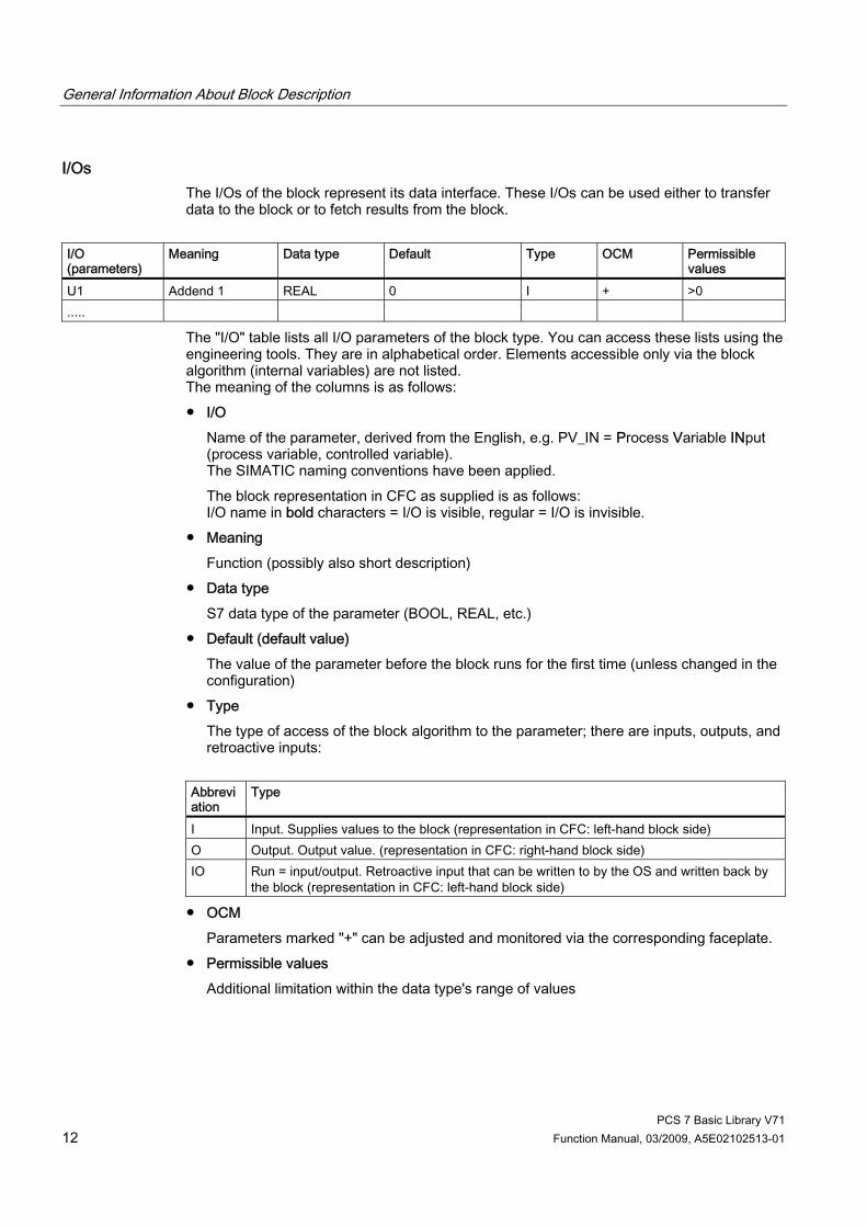
I/Os The I/Os of the block represent its data interface. These I/Os can be used either to transfer data to the block or to fetch results from the block.
I/O (parameters)
Meaning Data type Default Type OCM Permissible values
U1 Addend 1 REAL 0 I + >0 .....
The "I/O" table lists all I/O parameters of the block type. You can access these lists using the engineering tools. They are in alphabetical order. Elements accessible only via the block algorithm (internal variables) are not listed. The meaning of the columns is as follows: ● I/O
Name of the parameter, derived from the English, e.g. PV_IN = Process Variable INput (process variable, controlled variable). The SIMATIC naming conventions have been applied. The block representation in CFC as supplied is as follows: I/O name in bold characters = I/O is visible, regular = I/O is invisible.
● Meaning Function (possibly also short description)
● Data type S7 data type of the parameter (BOOL, REAL, etc.)
● Default (default value) The value of the parameter before the block runs for the first time (unless changed in the configuration)
● Type The type of access of the block algorithm to the parameter; there are inputs, outputs, and retroactive inputs:
Abbreviation
Type
I Input. Supplies values to the block (representation in CFC: left-hand block side) O Output. Output value. (representation in CFC: right-hand block side) IO Run = input/output. Retroactive input that can be written to by the OS and written back by
the block (representation in CFC: left-hand block side)
● OCM Parameters marked "+" can be adjusted and monitored via the corresponding faceplate.
● Permissible values Additional limitation within the data type's range of values

General Information About Block Description
PCS 7 Basic Library V71 Function Manual, 03/2009, A5E02102513-01 13
Operating and monitoring When a faceplate exists for the AS block, links to descriptions of the corresponding faceplate and block icon are available (also with the buttons in the upper part of the topic).

General Information About Block Description
PCS 7 Basic Library V71 14 Function Manual, 03/2009, A5E02102513-01
PCS 7 Basic Library V71 Function Manual, 03/2009, A5E02102513-01 15
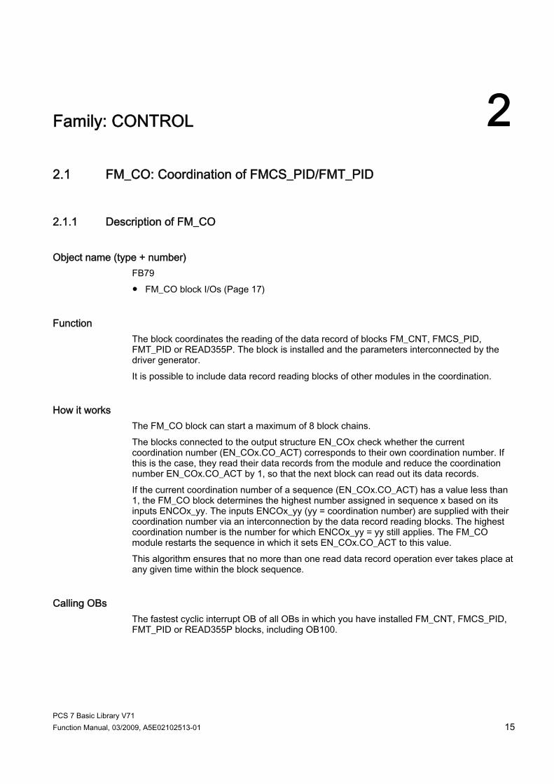
Family: CONTROL 22.1 FM_CO: Coordination of FMCS_PID/FMT_PID
2.1.1 Description of FM_CO
Object name (type + number) FB79 ● FM_CO block I/Os (Page 17)
Function The block coordinates the reading of the data record of blocks FM_CNT, FMCS_PID, FMT_PID or READ355P. The block is installed and the parameters interconnected by the driver generator. It is possible to include data record reading blocks of other modules in the coordination.
How it works The FM_CO block can start a maximum of 8 block chains. The blocks connected to the output structure EN_COx check whether the current coordination number (EN_COx.CO_ACT) corresponds to their own coordination number. If this is the case, they read their data records from the module and reduce the coordination number EN_COx.CO_ACT by 1, so that the next block can read out its data records. If the current coordination number of a sequence (EN_COx.CO_ACT) has a value less than 1, the FM_CO block determines the highest number assigned in sequence x based on its inputs ENCOx_yy. The inputs ENCOx_yy (yy = coordination number) are supplied with their coordination number via an interconnection by the data record reading blocks. The highest coordination number is the number for which ENCOx_yy = yy still applies. The FM_CO module restarts the sequence in which it sets EN_COx.CO_ACT to this value. This algorithm ensures that no more than one read data record operation ever takes place at any given time within the block sequence.
Calling OBs The fastest cyclic interrupt OB of all OBs in which you have installed FM_CNT, FMCS_PID, FMT_PID or READ355P blocks, including OB100.
Family: CONTROL 2.1 FM_CO: Coordination of FMCS_PID/FMT_PID
PCS 7 Basic Library V71 16 Function Manual, 03/2009, A5E02102513-01
Use in CFC When using the CFC function "Generate Module Drivers", the block is automatically installed and the connections, such as those described under "Installation regulation" are made. If you install, delete or move blocks of an existing block chain in other OBs or runtime groups, the driver generator must be called. Should the sequence not start up as expected (after CPU restart) or not continue to run (after downloading changes), you must set ACC_ID to 1.
Installation rules An FM_CO is responsible for a DP master system (chain). On this DP master system, a maximum of 8 DP slaves (only ET 200M) can be operated with at least one FM 350, FM 355 or FM 355-2 module. A standard rail can hold up to four FM 355 modules. An FM 355 can be configured for one to four controller channels, in other words, a maximum of 16 controller channels can be operated with one DP slave. In the following, only the FMCS_PID block , which also represents FM_CNT, FMT_PID or READ355P is taken into consideration. The FM_CO must always be installed before the first FMCS_PID block in the fastest cyclic interrupt OB. The output structure EN_COx for the rack x is connected to the input structures EN_COx of all FMCS_PID blocks, which communicate to controller modules of rack x. The output ENCO of each FMCS_PID block is connected to an input ENCOx_yy (yy corresponds to the coordination number CO_NO assigned to each FMCS_PID block) of the FM_CO block. As described above, 8 DP slaves can be operated with one FM_CO block on a DP master system. The selection of the cyclic interrupt OB depends on the CPU load. Note that the CPU has no reserves for other "Read data record" jobs if operating with eight DP slaves because only eight jobs can be buffered per DP master system. Simply inserting a module would lead to an overflow. It is advisable to operate only up to six DP slaves on a DP master system. The remaining DP slaves must be distributed on other DP master systems with further FM_CO blocks. When selecting the cyclic OB, remember that the new data will be available at the earliest after two cycles. Make sure that the maximum runtime of this OB does not have any negative impact on overall system runtime as a result of the number of blocks installed. If the FMCS_PID blocks to be processed exceed the runtime limit, group the DP slaves with the FM 355 modules in fast and slow control loops.
Startup characteristics EN_CO_x.CO_ACT = 1 is set at all outputs during startup (restart).
Time response Not available
Message response Not available

Family: CONTROL 2.1 FM_CO: Coordination of FMCS_PID/FMT_PID
PCS 7 Basic Library V71 Function Manual, 03/2009, A5E02102513-01 17
2.1.2 I/Os of FM_CO The factory setting of the block display in CFC is identified in the "I/O" column: I/O name in bold characters = I/O is visible; I/O name in regualr characters = I/O is invisible. You will find explanations of and information about the abbreviations used in "General information about the block description (Page 9)". I/O (parameters)
Meaning Data type Default
Type
ACC_ID Restart all sequences BOOL 1 IO ENCOx_yy The coordination number yy is assigned in the rack x
if the input has the value yy (x = 0 - 7, yy = 1 - 64) BYTE 0 I
EN_CO_x Coordination number of the block that can read data records
STRUCT 0 O

Family: CONTROL 2.1 FM_CO: Coordination of FMCS_PID/FMT_PID
PCS 7 Basic Library V71 18 Function Manual, 03/2009, A5E02102513-01

PCS 7 Basic Library V71 Function Manual, 03/2009, A5E02102513-01 19
Family: @System 33.1 CONEC: Monitoring the AS connection status
3.1.1 Description of CONEC
Object name (type + number) FB 88 ● CONEC Block I/Os (Page 22)
Area of application The CONEC block monitors the status of AS connections, and reports the associated error events.
Calling OBs The block must be installed in the run sequence in the following OBs: OB 100 Restart (warm start)
Use in CFC With the "Generate module drivers" CFC function, the CONEC block is automatically installed in the OBs listed above.
Function and operating principle The CONEC block generates messages which are output at ALARM_8P to WinCC (see "Message Response"). For connection diagnostics, SFC 87 (C_DIAG) is called every 10 seconds in the cyclic interrupt OB (OB 32). Up to 64 connections are monitored.
Note The messages "Failure or loss of redundancy connection ID" are generated by each CPU of the two connected AS except when the CPU of an AS fails (or both H-CPUs). The connection ID determines whether a message is output. If the connection ID >= 16#C00, no message is generated.

Family: @System 3.1 CONEC: Monitoring the AS connection status
PCS 7 Basic Library V71 20 Function Manual, 03/2009, A5E02102513-01
Generation of the maintenance status MS If any connection in the CONEC block is detected as having failed, the "Maintenance alarm" maintenance status is output. If any connection in the CONEC block is detected as a redundancy loss, the "Maintenance request" maintenance status is output. If in the CONEC block the messages are disabled via the parameter EN_MSG, then the maintenance status "Unchecked / Unknown" will be output.
Error handling Error handling for the block is limited to the evaluation of the error information of ALARM_8P. You will find more information in the "Error Information of Output Parameter MSG_STAT" (Page 322) section.
Startup characteristics The CONEC block initializes the messages of ALARM_8P. If there is a CPU with SFC 87, connection diagnostics is initialized. After this, there is a wait time of approx. 1 minute in the cyclic interrupt OB before the connection diagnostics messages are generated.
Overload behavior Not available
Time response For further information, refer to "Message response".
Message response The block generates the following messages in the OBs listed below: OB Start Event Message OB 32 1 sec. cyclic interrupt or
alternative cyclic interrupt OB Failure connection ID: xx incoming/outgoing Loss of redundancy connection ID: xx entering/exiting state
If EN_MSG = FALSE, messaging is disabled.

Family: @System 3.1 CONEC: Monitoring the AS connection status
PCS 7 Basic Library V71 Function Manual, 03/2009, A5E02102513-01 21
Operating and monitoring Note: If you have selected the "Enable operator control and monitoring" option in the block object properties in the CFC, the variables transferred to the OS are identified under "I/Os of ..." (OCM column, "+"). Default: Option not activated.
Additional information For further information, refer to the sections: Message texts and associated values of CONEC (Page 23) Maintenance status of MS (Page 326)

Family: @System 3.1 CONEC: Monitoring the AS connection status
PCS 7 Basic Library V71 22 Function Manual, 03/2009, A5E02102513-01
3.1.2 I/Os of CONEC The default block view in the CFC is identified in the "I/O" column: I/O name in bold = I/O is visible, standard I/O name = I/O is not visible. You will find explanations of, and information about the abbreviations used in "General information about the block description (Page 9)". I/O (parameters)
Meaning Data type Default
Type O&M
EN_MSG 1 = Enable message BOOL 1 I EV_IDx Message number for ALARM_8P_x
(x = 1 - 16, assigned by ES) DWORD 0 I
MS Maintenance status DWORD 0 I + MSGSTATx STATUS output of ALARM_8P_x (x = 1 - 16) WORD 0 O O_MS Maintenance status DWORD 0 O QMSGERx Error output of ALARM_8P_x (x = 1 - 16) BOOL 0 O SAMPLE_T Sampling time OB in seconds REAL 1.0 I
Additional information For further information, refer to the following sections: Message texts and associated values of CONEC (Page 23) Maintenance status of MS (Page 326)
Family: @System 3.1 CONEC: Monitoring the AS connection status
PCS 7 Basic Library V71 Function Manual, 03/2009, A5E02102513-01 23
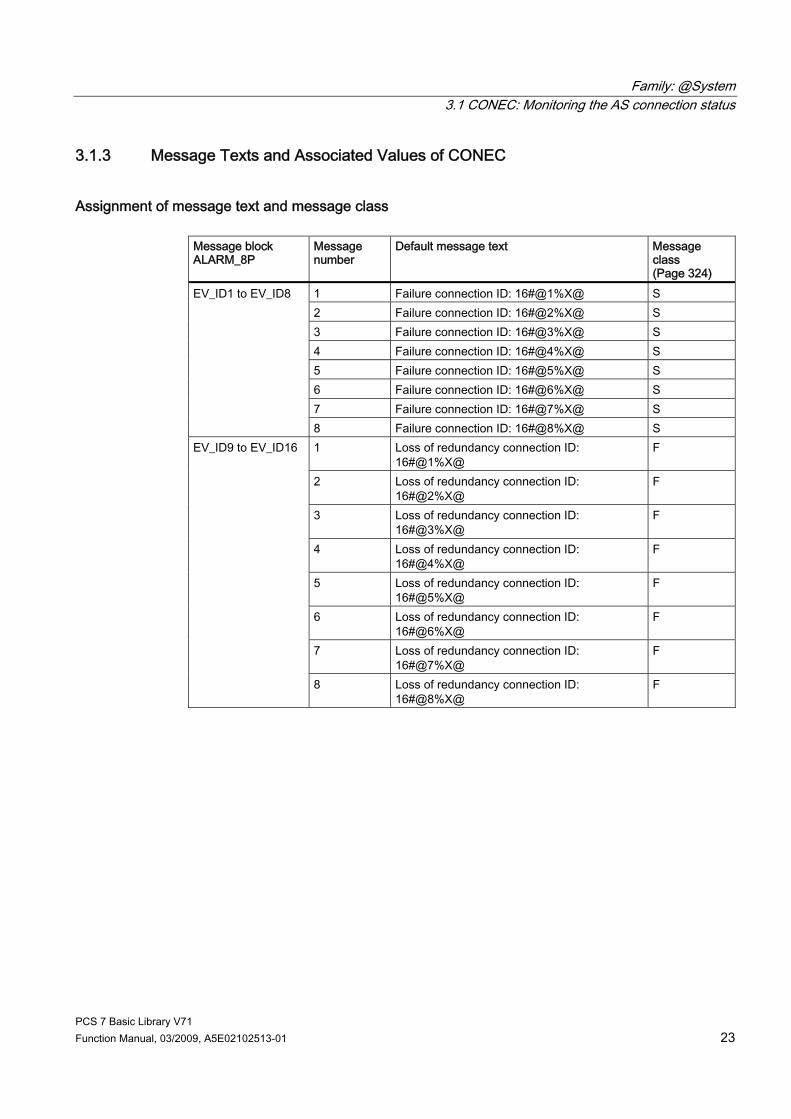
3.1.3 Message Texts and Associated Values of CONEC
Assignment of message text and message class Message block ALARM_8P
Message number
Default message text Message class (Page 324)
1 Failure connection ID: 16#@1%X@ S 2 Failure connection ID: 16#@2%X@ S 3 Failure connection ID: 16#@3%X@ S 4 Failure connection ID: 16#@4%X@ S 5 Failure connection ID: 16#@5%X@ S 6 Failure connection ID: 16#@6%X@ S 7 Failure connection ID: 16#@7%X@ S
EV_ID1 to EV_ID8
8 Failure connection ID: 16#@8%X@ S 1 Loss of redundancy connection ID:
16#@1%X@ F
2 Loss of redundancy connection ID: 16#@2%X@
F
3 Loss of redundancy connection ID: 16#@3%X@
F
4 Loss of redundancy connection ID: 16#@4%X@
F
5 Loss of redundancy connection ID: 16#@5%X@
F
6 Loss of redundancy connection ID: 16#@6%X@
F
7 Loss of redundancy connection ID: 16#@7%X@
F
EV_ID9 to EV_ID16
8 Loss of redundancy connection ID: 16#@8%X@
F

Family: @System 3.1 CONEC: Monitoring the AS connection status
PCS 7 Basic Library V71 24 Function Manual, 03/2009, A5E02102513-01
Assignment of associated values The process control messages are generated by ALARM_8P with EV_ID1 to EV_ID16 with 8 associated values. The table below shows how the associated values are assigned to the block parameters. Message block ALARM_8P
Associatedvalue
Block parameter Data type
1 Connection_ID 1+x WORD 2 Connection_ID 2+x WORD 3 Connection_ID 3+x WORD 4 Connection_ID 4+x WORD 5 Connection_ID 5+x WORD 6 Connection_ID 6+x WORD 7 Connection_ID 7+x WORD
EV_ID1... EV_ID16
8 Connection_ID 8+x WORD
x = 0 for EV_ID1, x = 8 for EV_ID2, x = 16 for EV_ID3 etc. to x = 56 for EV_ID8 x = 0 for EV_ID9, x = 8 for EV_ID10, x = 16 for EV_ID11 etc. to x = 56 for EV_ID16
Family: @System 3.2 CPU_RT: Determination of the runtime of OBs
PCS 7 Basic Library V71 Function Manual, 03/2009, A5E02102513-01 25
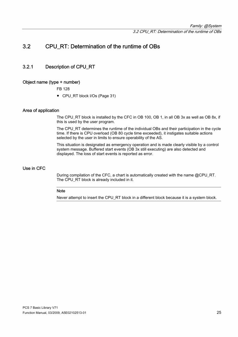
3.2 CPU_RT: Determination of the runtime of OBs
3.2.1 Description of CPU_RT
Object name (type + number) FB 128 ● CPU_RT block I/Os (Page 31)
Area of application The CPU_RT block is installed by the CFC in OB 100, OB 1, in all OB 3x as well as OB 8x, if this is used by the user program. The CPU_RT determines the runtime of the individual OBs and their participation in the cycle time. If there is CPU overload (OB 80 cycle time exceeded), it instigates suitable actions selected by the user in limits to ensure operability of the AS. This situation is designated as emergency operation and is made clearly visible by a control system message. Buffered start events (OB 3x still executing) are also detected and displayed. The loss of start events is reported as error.
Use in CFC During compilation of the CFC, a chart is automatically created with the name @CPU_RT. The CPU_RT block is already included in it.
Note Never attempt to insert the CPU_RT block in a different block because it is a system block.

Family: @System 3.2 CPU_RT: Determination of the runtime of OBs
PCS 7 Basic Library V71 26 Function Manual, 03/2009, A5E02102513-01
Function and operating principle At CPU restart and when downloading changes the slowest OB 3x is determined with SZL ID 822 (data records of all assigned alarms of an alarm class). Note: The slowest cyclic OB 3x (slowest OB) must also have the lowest priority set so that a useful analysis is possible. In OB-BEGIN, if there are implausible settings, a message EV_ID2 signal 3 "Priorities of cyclic OBs do not conform to PCS 7" is output and the maintenance status (MS is set to "Maintenance demand" = 16#00000005). SFC78 is used to determine the OB runtimes. If it is not present, no warning limit will be output as a message.
Note Older CPUs do not support SFC78. Use SZL112 to check whether SFC78 is available.
Note The status of CPU_RT is reset when you download.
Behavior at higher CPU load If the average value of all net runtimes (in % of OB 3x, OB 8x + OB 1) exceeds the value MAX_LIM, then in OB_BEGIN, the message EV_ID2- signal 1 "Net time consumption of all OBs exceeds max limit" is output. The maintenance status MS is set to "Maintenance demand" = 16#00000005 in OB_BEGIN. The message and MS are cleared with a value less than MAX_LIM – HYS.
Behavior in the event of OB request errors If a selectable number of these OB 3x events has been exceeded, or if an OB 1 event is detected, without an OB 1 having been processed, the message EV_ID3 – Signal 2 "OB request: OB 3x still being processed". is output in OB_BEGIN. The number of OB 3x events can be set at the input "N_REG_ERR"; the default value = 4. The maintenance status MS is set to "Uncertain maintenance request" = 16#00000006 in OB_BEGIN. If an OB 1 is then run through again, the MS is reset and this control system message will be marked as "exiting state". In the faceplate of OB_BEGIN, there is a display of the request error for each OB 3x. The first occurrence of a request error is be displayed. These displays can be reset with the reset key.
Family: @System 3.2 CPU_RT: Determination of the runtime of OBs
PCS 7 Basic Library V71 Function Manual, 03/2009, A5E02102513-01 27
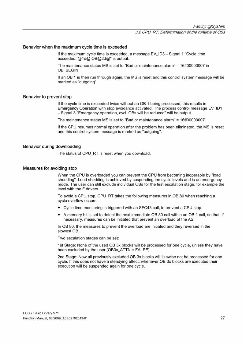
Behavior when the maximum cycle time is exceeded If the maximum cycle time is exceeded, a message EV_ID3 – Signal 1 "Cycle time exceeded: @1d@ OB@2d@" is output. The maintenance status MS is set to "Bad or maintenance alarm" = 16#00000007 in OB_BEGIN. If an OB 1 is then run through again, the MS is reset and this control system message will be marked as "outgoing".
Behavior to prevent stop If the cycle time is exceeded twice without an OB 1 being processed, this results in Emergency Operation with stop avoidance activated. The process control message EV_ID1 – Signal 3 "Emergency operation, cycl. OBs will be reduced" will be output. The maintenance status MS is set to "Bad or maintenance alarm" = 16#00000007. If the CPU resumes normal operation after the problem has been eliminated, the MS is reset and this control system message is marked as "outgoing".
Behavior during downloading The status of CPU_RT is reset when you download.
Measures for avoiding stop When the CPU is overloaded you can prevent the CPU from becoming inoperable by "load shedding". Load shedding is achieved by suspending the cyclic levels and is an emergency mode. The user can still exclude individual OBs for the first escalation stage, for example the level with the F drivers. To avoid a CPU stop, CPU_RT takes the following measures in OB 80 when reaching a cycle overflow occurs: ● Cycle time monitoring is triggered with an SFC43 call, to prevent a CPU stop. ● A memory bit is set to detect the next immediate OB 80 call within an OB 1 call, so that, if
necessary, measures can be initiated that prevent an overload of the AS. In OB 80, the measures to prevent the overload are initiated and they reversed in the slowest OB. Two escalation stages can be set: 1st Stage: None of the used OB 3x blocks will be processed for one cycle, unless they have been excluded by the user (OB3x_ATTN = FALSE). 2nd Stage: Now all previously excluded OB 3x blocks will likewise not be processed for one cycle. If this does not have a steadying effect, whenever OB 3x blocks are executed their execution will be suspended again for one cycle.

Family: @System 3.2 CPU_RT: Determination of the runtime of OBs
PCS 7 Basic Library V71 28 Function Manual, 03/2009, A5E02102513-01
Assign the parameters in CPU_RT for each OB 3x at the following inputs: OB3x_ATTN = TRUE The OB is included in the measures to prevent overload. Default is
"TRUE".
The maximum number of SFC43 calls can be set at the input MAX_RTRG. If the maximum number x is exceeded, the CPU goes to stop. The number x is reset when there is an OB 1 call again. If you set MAX_RTRG = 0, then the function stop avoidance on overload function is deactivated. If the measures are effective, in other words OB 1 is run through again, a calculation is made at that point to determine whether canceling the measures would again result in overload. If yes, the measures remain in effect. The measures are reduced step-by-step, when safe operation is possible again.
Reversal of the measures for stop avoidance To initiate a reversal the percentage sum of the cyclic OBs calculated back to a lower reduction ratio, must be less than full CPU utilization. Use the parameter MAX_VAL to set the value that corresponds to full CPU utilization. The value "95" is default. The calculation is made according to the following formula: ((NET30PERint * (OB30_N_START+1) / OB30_N_START)+ (NET31PERint * (OB31_N_START+1) / OB31_N_START)+ (NET32PERint * (OB32_N_START+1) / OB32_N_START)+ (NET33PERint * (OB33_N_START+1) / OB33_N_START)+ (NET34PERint * (OB34_N_START+1) / OB34_N_START)+ (NET35PERint * (OB35_N_START+1) / OB35_N_START)+ (NET36PERint * (OB36_N_START+1) / OB36_N_START)+ (NET37PERint * (OB37_N_START+1) / OB37_N_START)+ (NET38PERint * (OB38_N_START+1) / OB38_N_START)+ NET01PER)< MAX_VAL NETxxPERint is the percentage share of a cyclic OB in the total runtime as a mean value and (OB30_N_START+1) is the current reduction factor of the OB. The net percentage values are also mean values, because in case of reduction, averaging is a must. For the calculation, a separate mean value generation was used that has a separate sample factor (SAMPLE_RE). If the condition is satisfied, then after a number of cycles in the slowest OB (parameter "UndoCycle") the reduction factor is decremented by 1 for all OBs. If the total sum of the OBs is still below MAX_VAL after this, then after a number of cycles in the slowest OB (UndoCycle), the factor will continue to be decremented until the used cyclic OBs have reached the reduction factor 1. After this, for the OBs (OB3x_ATTN = FALSE) excluded by the user, the reduction ratio will be set to 0.
Family: @System 3.2 CPU_RT: Determination of the runtime of OBs
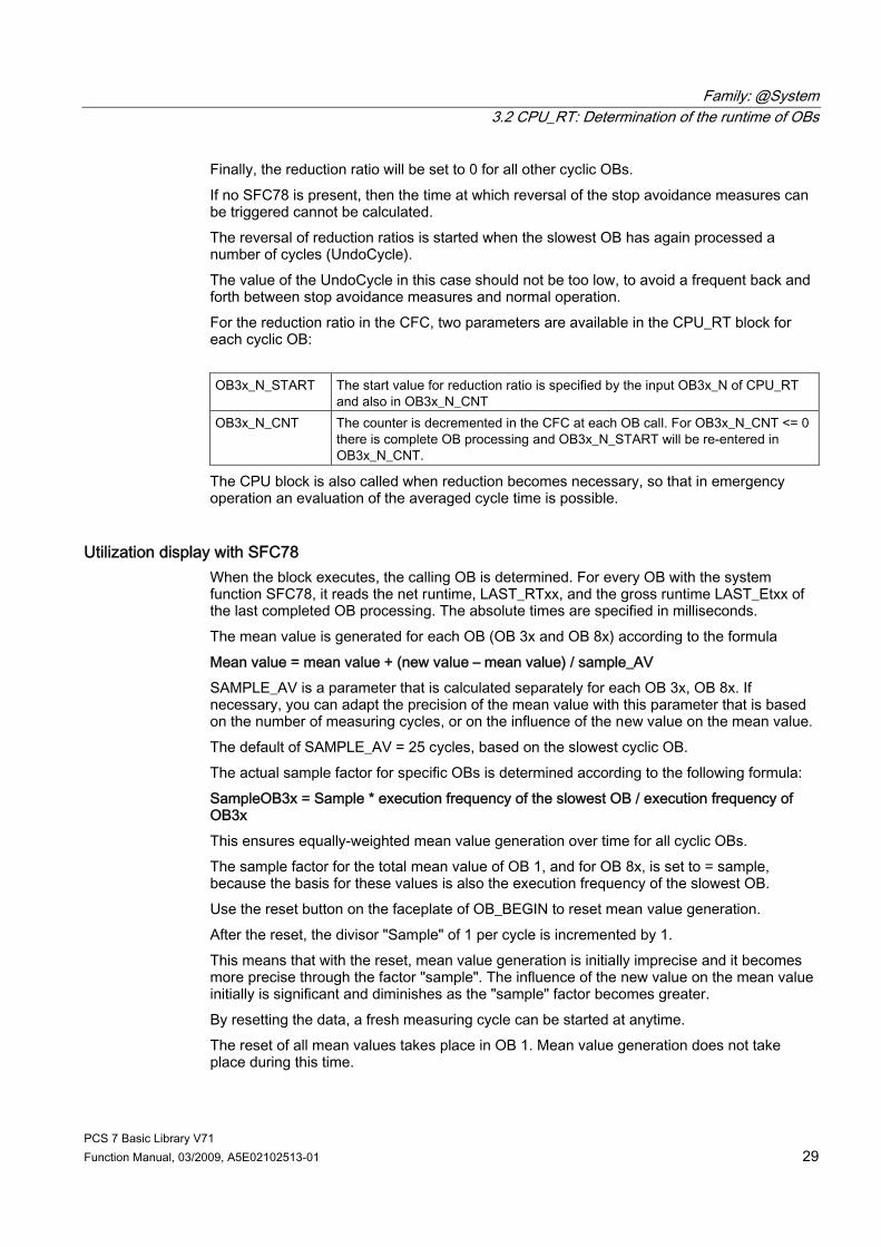
PCS 7 Basic Library V71 Function Manual, 03/2009, A5E02102513-01 29
Finally, the reduction ratio will be set to 0 for all other cyclic OBs. If no SFC78 is present, then the time at which reversal of the stop avoidance measures can be triggered cannot be calculated. The reversal of reduction ratios is started when the slowest OB has again processed a number of cycles (UndoCycle). The value of the UndoCycle in this case should not be too low, to avoid a frequent back and forth between stop avoidance measures and normal operation. For the reduction ratio in the CFC, two parameters are available in the CPU_RT block for each cyclic OB: OB3x_N_START The start value for reduction ratio is specified by the input OB3x_N of CPU_RT
and also in OB3x_N_CNT OB3x_N_CNT The counter is decremented in the CFC at each OB call. For OB3x_N_CNT <= 0
there is complete OB processing and OB3x_N_START will be re-entered in OB3x_N_CNT.
The CPU block is also called when reduction becomes necessary, so that in emergency operation an evaluation of the averaged cycle time is possible.
Utilization display with SFC78 When the block executes, the calling OB is determined. For every OB with the system function SFC78, it reads the net runtime, LAST_RTxx, and the gross runtime LAST_Etxx of the last completed OB processing. The absolute times are specified in milliseconds. The mean value is generated for each OB (OB 3x and OB 8x) according to the formula Mean value = mean value + (new value – mean value) / sample_AV SAMPLE_AV is a parameter that is calculated separately for each OB 3x, OB 8x. If necessary, you can adapt the precision of the mean value with this parameter that is based on the number of measuring cycles, or on the influence of the new value on the mean value. The default of SAMPLE_AV = 25 cycles, based on the slowest cyclic OB. The actual sample factor for specific OBs is determined according to the following formula: SampleOB3x = Sample * execution frequency of the slowest OB / execution frequency of OB3x This ensures equally-weighted mean value generation over time for all cyclic OBs. The sample factor for the total mean value of OB 1, and for OB 8x, is set to = sample, because the basis for these values is also the execution frequency of the slowest OB. Use the reset button on the faceplate of OB_BEGIN to reset mean value generation. After the reset, the divisor "Sample" of 1 per cycle is incremented by 1. This means that with the reset, mean value generation is initially imprecise and it becomes more precise through the factor "sample". The influence of the new value on the mean value initially is significant and diminishes as the "sample" factor becomes greater. By resetting the data, a fresh measuring cycle can be started at anytime. The reset of all mean values takes place in OB 1. Mean value generation does not take place during this time.

Family: @System 3.2 CPU_RT: Determination of the runtime of OBs
PCS 7 Basic Library V71 30 Function Manual, 03/2009, A5E02102513-01
Error handling If the read-out of data from the cyclic OB fails for the CPU_RT block, then ERR_NUM = 1 is set and processing of the CPU_RT block is abandoned, because these data are the basic prerequisite for useful processing.
Startup characteristics Calculations with SFC78 are restarted only after a number of cycles (RunUpCyc) after restart. The RunUpCyles are counted down in the slowest cyclic OB.
Time response Not applicable.
Message response The block reports via OB_BEGIN (Page 183)
Operator control and monitoring: Note: If you have selected the "Enable operator control and monitoring" option in the block object properties in the CFC, the variables transferred to the OS are identified under "I/Os of ..." (OCM column, "+"). Default: Option not activated. If asset management is used in the project and the diagnostics screens have been generated, the faceplate can be called via the block icon of the AS. ● OB_BEGIN faceplate (Page 292) ● Asset management block icons (Page 284) If no asset management is used in the project, the "OB-BEGIN" block icon is used to display avoidance of stop. See also: Display for avoiding stop without asset management (Page 281)
Additional information You will find more information on this subject in the following sections: Message texts and associated values of OB_BEGIN (Page 189) Maintenance status of MS (Page 326)

Family: @System 3.2 CPU_RT: Determination of the runtime of OBs
PCS 7 Basic Library V71 Function Manual, 03/2009, A5E02102513-01 31
3.2.2 I/Os of CPU_RT The factory setting of the block display in CFC is identified in the "I/O" column: I/O name bold = I/O visible, I/O name normal = I/O not visible. You will find explanations of, and information about the abbreviations used in "General information about the block description (Page 9)".
I/O Meaning Type Preset Type
O&M
CPU_RT_DATA System structure: Performance data STRUCT O DAT_PLAU 1 = slowest OB 3x has the lowest priority BOOL 0 O DELTA_L Flag for change compile BOOL 1 I ERR_NUM 1 = occurrence of an error INT O EXC_FR3x (x = 0 – 8) execution cycle (in ms) of the OB 3x INT 0 O + GRO3xAV (x = 0 – 8) gross mean value REAL 0 O + GRO3xCUR (x = 0 – 8) gross current value REAL 0 O + GRO3xMAX (x = 0 – 8) gross maximum value REAL 0 O + GRO3xMIN (x = 0 – 8) gross minimum value REAL 0 O + GRO3xPER (x = 0 – 8) gross mean value (in %) REAL 0 O + HYS Hysteresis of the max. total number INT 5 I + IDLE_CYC CPU utilization display INT 0 MAX_LIM Max. total number REAL 75 I + MAX_RTRG Max. number of calls (for SFC 43) INT 50 I MAX_VAL Max. value for calculating the reset of reduction ratios REAL 95 I + MAXCYCTI Set scan cycle monitoring time INT 0 O + N_OB1_CYC Number of OB 1 calls during a cycle of the slowest OB INT 0 O N_REQ_ERR Number of OB 3x request errors INT 4 I NET01AV Net mean value of OB 1 (in ms) REAL 0 O + NET01CUR Net current value of OB 1 (in ms) REAL 0 O + NET01MAX Net maximum value of OB 1 (in ms) REAL 0 O + NET01MIN Net minimum value of OB 1 (in ms) REAL 0 O + NET01PER Net mean value of OB 1 (in %) REAL 0 O + NET3xAV (x = 0 – 8) net mean value of OB 3x (in ms) REAL 0 O + NET3xCUR (x = 0 – 8) net current value of OB 3x (in ms) REAL 0 O + NET3xMAX (x = 0 – 8) net maximum value of OB 3x (in ms) REAL 0 O + NET3xMIN (x = 0 – 8) net minimum value of OB 3x (in ms) DINT 0 O + NET3xPER (x = 0 – 8) net mean value of OB 3x (in %) REAL 0 O + NET8xAV (x = 0 – 8) net mean value of OB 8x (in ms) REAL 0 O + NET8xCUR (x = 0 – 8) net current value of OB 8x (in ms) REAL 0 O + NET8xMAX (x = 0 – 8) net maximum value of OB 8x (in ms) REAL 0 O + NET8xPER (x = 0 – 8) net mean value of OB 8x (in %) REAL 0 O + OB3x_ATTN (x = 0 – 8) OB 3x: 1 = participates in measures to prevent
overloads BOOL 1 I
OB3x_N_CNT (x = 0 – 8) decrementing counter for reduction ratio INT 0 O OB3x_N_START (x = 0 – 8) start value for reduction ratio INT 0 O

Family: @System 3.2 CPU_RT: Determination of the runtime of OBs
PCS 7 Basic Library V71 32 Function Manual, 03/2009, A5E02102513-01
I/O Meaning Type Preset Type
O&M
REQ01ERR (x = 0 – 8) OB request errors since the last reset BOOL 0 O + REQ3xERR (x = 0 – 8) OB request errors BOOL 0 O + RESET Resets the mean values, minimum values, and maximum
values BOOL 1 I +
RUNUPCYC Number of start-up cycles INT 5 I SAMPLE_AV Sample factor for mean value generation INT 50 I SAMPLE_RE Sample factor for mean value generation internal INT 50 I SFC78_EX 1 = SFC 78 available in CPU BOOL 0 O + SL_OB Slowest OB 3x BYTE 0 O SL_OB_EXC_FR Number of calls of the slowest OB 3x INT 0 O TOTALAV Total average value of all OB 1, OB 3x, OB 8x (in %) DINT 0 O + TOTALCUR Total current value of all OB 1, OB 3x, OB 8x (in %) DINT 0 O + TOTALMAX Total maximum value of all OB 1, OB 3x, OB 8x (in %) DINT 0 O + TOTALMIN Total minimum value of all OB 1, OB 3x, OB 8x (in %) DINT 0 O + UNDO_CYC Counter in the slowest OB for emergency operation INT 100 I
Additional information You will find more information on this subject in the following sections: Message texts and associated values of OB_BEGIN (Page 189)
See also Maintenance Status of MS (Page 326)
Family: @System 3.3 DIAG_AB: Evaluation of statusword AB7000
PCS 7 Basic Library V71 Function Manual, 03/2009, A5E02102513-01 33
3.3 DIAG_AB: Evaluation of statusword AB7000
3.3.1 Description of DIAG_OB
Object name (type + number) FB 414 ● DIAG_AB Block I/Os (Page 35)
Area of application The DIAG_AB block evaluates the status word of an AB7000 slave and acknowledges newly reported errors via the control word of the slave.
Calling OBs The cyclic OB and OB 100.
Use in CFC The following actions are executed automatically with the "Generate module drivers" CFC function: ● The block is installed in the run sequence before the MOD_PAL0 or MOD_PAX0 block,
both of which are also installed by the driver generator. The install is executed in the same cyclic OB as the associated signal processing blocks FF_A_xx.
● Parameters are assigned to the LADDR_C input with the address of the control word of the AB7000.
● Parameters are assigned to the input LADDR_S with the address control word of the AB7000.
● The OUT structure CPU_DIAG of the OB_BEGIN block is interconnected with the IN_OUT structures of the same name of DIAG_AB.
● The input mode of the DIAG_AB block is interconnected with the output OMODE_00 of the PADP_L10 or PADP_L01 block.
● The input PA_DIAG of the DIAG_AB block is interconnected with the output PA_DIAG of the PADP_L10 or PADP_L01 block.
● The output OMODE of the DIAG_AB block is interconnected with the input MODE_00 of the MOD_PAL0 or MOD_PAX0 block.
● The output ODIAG of the DIAG_AB block is interconnected with the input PA_DIAG of the MOD_PAL0 or MOD_PAX0 block.
Family: @System 3.3 DIAG_AB: Evaluation of statusword AB7000
PCS 7 Basic Library V71 34 Function Manual, 03/2009, A5E02102513-01
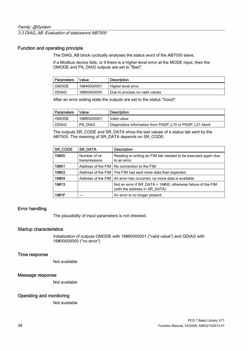
Function and operating principle The DIAG_AB block cyclically analyses the status word of the AB7000 slave, If a Modbus device fails, or if there is a higher-level error at the MODE input, then the OMODE and PA_DIAG outputs are set to "Bad": Parameters Value Description OMODE 16#40000001 Higher level error ODIAG 16#00400000 Due to process no valid values
After an error exiting state the outputs are set to the status "Good": Parameters Value Description OMODE 16#80000001 Valid value ODIAG PA_DIAG Diagnostics information from PADP_L10 or PADP_L01 block
The outputs SR_CODE and SR_DATA show the last values of a status tab sent by the AB7000. The meaning of SR_DATA depends on SR_CODE: SR_CODE SR_DATA Description 16#00 Number of re-
transmissions Reading or writing an FIM tab needed to be executed again due to an error
16#01 Address of the FIM No connection to the FIM 16#03 Address of the FIM The FIM has sent more data than expected 16#04 Address of the FIM An error has occurred, no more data is available 16#13 Not an error if SR_DATA = 16#00, otherwise failure of the FIM
(with the address in SR_DATA) 16#1F --- An error is no longer present
Error handling The plausibility of input parameters is not checked.
Startup characteristics Initialization of outputs OMODE with 16#80000001 ("valid value") and ODIAG with 16#00000000 ("no error")
Time response Not available
Message response Not available
Operating and monitoring Not available

Family: @System 3.3 DIAG_AB: Evaluation of statusword AB7000
PCS 7 Basic Library V71 Function Manual, 03/2009, A5E02102513-01 35
3.3.2 I/Os of DIAG_AB The factory setting of the block display in the CFC is identified in the "I/O" column: I/O name bold = I/O visible, I/O name normal = I/O not visible. You will find explanations of, and information about the abbreviations used in the "General information about the block description" (Page 9) section. I/O
Meaning
Type
Default Type
OCM
CPU_DIAG CPU diagnostics (system structure) STRUCT IO LADDR_C Logical address of the control word INT 0 I LADDR_S Logical address of the control word INT 0 I MODE Value status DWORD 16#80 000 000 I ODIAG Field devices diagnostics information DWORD 0 O OMODE Value status of the slave DWORD 0 O PA_DIAG Diagnostic information DWORD 0 I SR_CODE Code of the status tab BYTE 0 O SR_DATA Data of the status tab BYTE 0 O

Family: @System 3.4 DPAY_V0: Monitoring DP/PA and Y-Link operating as V0 slave
PCS 7 Basic Library V71 36 Function Manual, 03/2009, A5E02102513-01
3.4 DPAY_V0: Monitoring DP/PA and Y-Link operating as V0 slave
3.4.1 Description of DPAY_V0
Object name (type + number) FB 108 ● DPAY_V0 Block I/Os (Page 41)
Area of application Block DPAY_V0 monitors the status of a DP/PA or Y-Link as a V0 slave (IM 157) and reports the corresponding error events. The DP/PA link operates as a PA master for the lower-level PA field devices and as a slave on the DP bus. The Y-Link operates as a DP master for the lower-level DP field devices and as a slave on the higher-level DP bus.
Calling OBs The block must be installed in the run sequence in the following OBs: OB 1 Cyclic program OB 70 I/O redundancy error OB 72 CPU redundancy error OB 82 Diagnostic interrupt OB 85 Program execution error OB 86 Rack failure OB 100 Restart (warm start)

Family: @System 3.4 DPAY_V0: Monitoring DP/PA and Y-Link operating as V0 slave
PCS 7 Basic Library V71 Function Manual, 03/2009, A5E02102513-01 37
Use in CFC The following actions are executed automatically with the "Generate module drivers" CFC function: ● The block is integrated in the run sequence downstream from the SUBNET block and
upstream from the PADP_L0x block. ● RACK_NO (rack/station number) is configured. ● SUBN_TYP (internal/external Profibus interface) is set. ● SUBN1_ID (ID of the master systems) is set. ● SUBN2_ID (ID of the redundant master system) is set. ● DADDR (diagnostic address of the DP/PA or Y-Link) is set. ● DPPA_xx (slave xx address), 1st module (slot) address of slave xx in the link, number of
slots of slave xx are set. ● The CPU_DIAG of the OB_BEGIN block and SUB_DIAG of the SUBNET block OUT
structures are interconnected with the IN_OUT structures of the same name of DPAY_V0. ● In the case of PA or DP field devices, they are interconnected with PADP_L0x.
Function and operating principle If redundancy losses and link failures occur, the DPAY_V0 block generates a control-system error message for the OS. The block also indicates error events at active links (SUBN1ERR, SUBN2ERR) and at the preferred channel (SUBN1ACT, SUBN2ACT) in the output status bar. The output structure RAC_DIAG contains the geographic address of the link as well as the group error information RACK_ERR. The corresponding link is not available if RACK_ERR = 1. The block requires a PROFIBUS DP interface. This can either be integrated in the CPU or provided by means of an external DP interface (CP). PROFIBUS DP is converted to PROFIBUS PA by means of a SIMATIC DP/PA-Link. The field devices of a link are always addressed at the higher-level DP bus via the DP address of IM 157. The AS addresses the field devices via the link, i.e., indirectly. The topological structure of the PA bus is mapped in the flat structure of the slave interface. A maximum of 64 field devices can be operated downstream from a link. Each field device can use any number of virtual slots at the link, up to 223 maximum. In order to enable the assignment of diagnostic data to the field devices, the block provides each field device a DPPA_xx input structure consisting of 3 bytes with the following contents: ● Byte (SLAV_NO) = node number (address) of the field device at the PA/DP master
system of the LINK ● Byte (SLOT_NO) = 1st module address of the field device in the link ● Byte (SLAV_SL) = number of slots of the field device The "Generate module drivers" CFC function fetches this data from HW Config. The start information is read from the CPU_DIAG I/O structure. This structure must be interconnected to the CPU_DIAG structure of the OB_BEGIN block (carried out by the CFC function "Generate module drivers").

Family: @System 3.4 DPAY_V0: Monitoring DP/PA and Y-Link operating as V0 slave
PCS 7 Basic Library V71 38 Function Manual, 03/2009, A5E02102513-01
The block generates a corresponding message (see "Message Response") on the basis of the startup information of calling OBs, if the current instance is affected. When operating with redundant PROFIBUS DP interfaces, the block determines the currently active preferred channel (SUBN1ACT, SUBN2ACT) by evaluating the error events as well as via the diagnostic address DADDR of the link. SFC 13 (DPNRM_DG, read diagnostic data consistently) reads the diagnostic data (OB 82). The reading process can take several cycles (OB 1). It is therefore possible in a few rare cases that the triggering diagnostic event cannot be recognized. Diagnostic user data contains information about the status of the link, and of connected field devices. The structure DPPA_ST indicates the link status. The status of a field device is entered in the structure DPA_M_xx. A field device can have a maximum of 32 slots (modules). Three block types are available, according to the number of slots on the field device: ● PADP_L00 (field device with max. 7 slots) ● PADP_L01 (field device with max. 16 slots) ● PADP_L02 (field device with max. 32 slots) The structure DPA_M_xx is interconnected to the structure DPA_M and the output EN_Mx with EN of one of the PADP_Lxx blocks (carried out by the CFC function "Generate module drivers"). The DPA_M_xx structure consists of two DWORD value (S_01 for modules 1 to 16 and S_02 for modules 17 to 32) and one BOOL value (S_ERR = DP/PA field device faulty). Two bits of the DWORD are assigned to each slot of the DP/PA field device, whereby bit 0 and bit 1 belong to slot 1 (module 1) of the DP/PA field device, etc. These bits are defined as follows: Status Bit 0 Status Bit 1 Meaning 0 0 Module x OK (valid user data) 0 1 Module x error (invalid user data) 1 0 Wrong module x (invalid user data) 1 1 No module x (invalid user data)
If the diagnostics alarm applies to the entire DP/PA field device, then DPA_M_xx.S_ERR = TRUE is set. Note: If you want to change the SUBN1_ID (connection to CPU 0) and SUBN2_ID (connection to CPU 1) inputs online, you must set input ACC_ID = TRUE. This will check the link states, and update the output values.
Redundancy The block supports redundant DP master systems in an H system (only distributed I/Os). The SUBN1_ID (connection to CPU 0) and SUBN2_ID (connection to CPU 1) inputs of the SUBNET block are configured with the numbers of the redundant DP master systems. If the DP master systems are not redundant, the remaining input is set to 16#FF (default).

Family: @System 3.4 DPAY_V0: Monitoring DP/PA and Y-Link operating as V0 slave
PCS 7 Basic Library V71 Function Manual, 03/2009, A5E02102513-01 39
Error handling The error handling for the block is limited to evaluation of the error information of ALARM_8P. You will find more information about this in the Error information of the MSG_STAT output parameter (Page 322)" section.
Startup characteristics The block initializes the messages of ALARM_8P. Availability of the link is verified. In H systems, determines the preferred channel of the link.
Overload behavior The block counts OB 86 (no DP master system failure, see SUBNET block) and OB 82 calls. Both counters are reset in OB 1. If more than five OB 86 events or more than five OB 82 events in succession before the cycle control point is reached (OB 1), these events are discarded and the message ""DP-Link DP-Master:x Rack:y: Multiple failure" or the message "DP-Link Master:x Rack:y: Muktiple alarm (OB 82)" is output. 1 minute later the status of the link will be re-checked.
Time response Not available
Message response After its call by OB 70, OB 72, OB 85 or OB 86, the block analyzes the status of its assigned CPU, DP master and link. If the link loses redundancy or fails, the block outputs corresponding messages via ALARM_8P. The block generally reports only the events generated in the link that it monitors. Redundancy loss and link failures which are caused by the failure of a DP masters or of a CPU, are initially neither signaled nor indicated at the outputs SUBN1ERR and SUBN2ERR. The DELAY input is used to delay the output of error messages for higher-priority outgoing errors. This delay time is configurable. When the block recognizes an outgoing error at an interconnected DP master, it initially assumes that there is a faulty assigned DP slave in the link it monitors and sets the corresponding output SUBNxERR. The error status is not reset until the DP slave returns (in this case: OB 86, OB 70). The blocks delay error messages relevant to any slave failure states for a time in seconds as specified in DELAY, in order not to trigger the output of surge of messages from DP slaves which are not yet synchronized after the master has returned. An error message is not output to the OS unless the DP slave has reported its return before this delay time has expired. Do not set the value of DELAY too high, since messages reporting faulty DP slaves or their removal during a master failure will be output too late to the OS after the DP master returns.
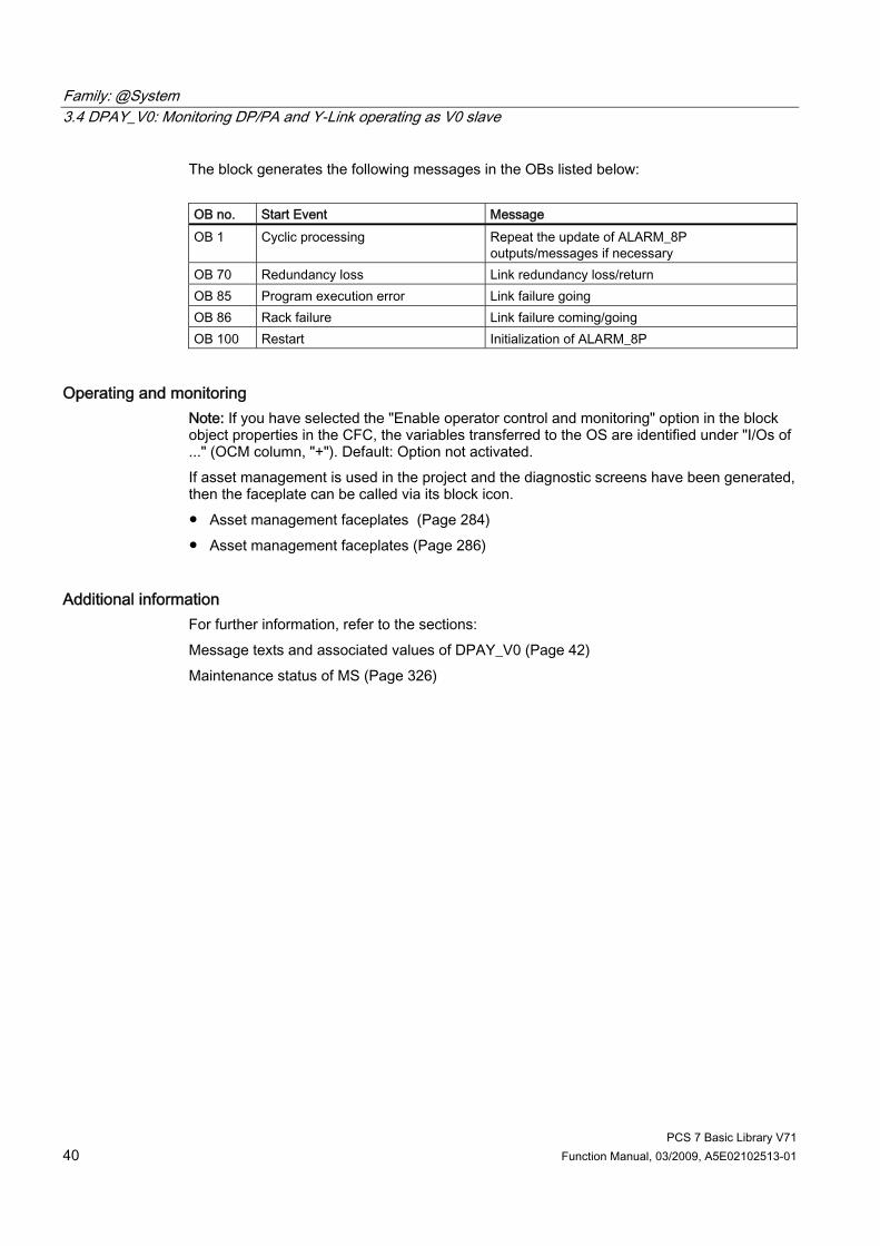
Family: @System 3.4 DPAY_V0: Monitoring DP/PA and Y-Link operating as V0 slave
PCS 7 Basic Library V71 40 Function Manual, 03/2009, A5E02102513-01
The block generates the following messages in the OBs listed below: OB no. Start Event Message OB 1 Cyclic processing Repeat the update of ALARM_8P
outputs/messages if necessary OB 70 Redundancy loss Link redundancy loss/return OB 85 Program execution error Link failure going OB 86 Rack failure Link failure coming/going OB 100 Restart Initialization of ALARM_8P
Operating and monitoring Note: If you have selected the "Enable operator control and monitoring" option in the block object properties in the CFC, the variables transferred to the OS are identified under "I/Os of ..." (OCM column, "+"). Default: Option not activated. If asset management is used in the project and the diagnostic screens have been generated, then the faceplate can be called via its block icon. ● Asset management faceplates (Page 284) ● Asset management faceplates (Page 286)
Additional information For further information, refer to the sections: Message texts and associated values of DPAY_V0 (Page 42) Maintenance status of MS (Page 326)
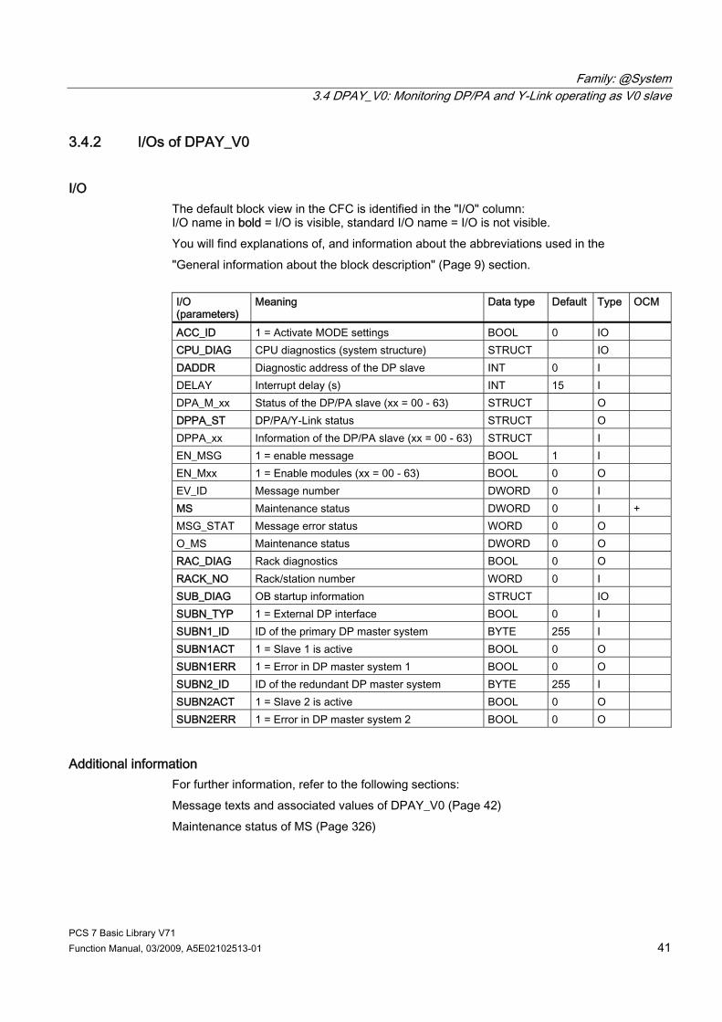
Family: @System 3.4 DPAY_V0: Monitoring DP/PA and Y-Link operating as V0 slave
PCS 7 Basic Library V71 Function Manual, 03/2009, A5E02102513-01 41
3.4.2 I/Os of DPAY_V0
I/O The default block view in the CFC is identified in the "I/O" column: I/O name in bold = I/O is visible, standard I/O name = I/O is not visible. You will find explanations of, and information about the abbreviations used in the "General information about the block description" (Page 9) section. I/O (parameters)
Meaning
Data type
Default Type
OCM
ACC_ID 1 = Activate MODE settings BOOL 0 IO CPU_DIAG CPU diagnostics (system structure) STRUCT IO DADDR Diagnostic address of the DP slave INT 0 I DELAY Interrupt delay (s) INT 15 I DPA_M_xx Status of the DP/PA slave (xx = 00 - 63) STRUCT O DPPA_ST DP/PA/Y-Link status STRUCT O DPPA_xx Information of the DP/PA slave (xx = 00 - 63) STRUCT I EN_MSG 1 = enable message BOOL 1 I EN_Mxx 1 = Enable modules (xx = 00 - 63) BOOL 0 O EV_ID Message number DWORD 0 I MS Maintenance status DWORD 0 I + MSG_STAT Message error status WORD 0 O O_MS Maintenance status DWORD 0 O RAC_DIAG Rack diagnostics BOOL 0 O RACK_NO Rack/station number WORD 0 I SUB_DIAG OB startup information STRUCT IO SUBN_TYP 1 = External DP interface BOOL 0 I SUBN1_ID ID of the primary DP master system BYTE 255 I SUBN1ACT 1 = Slave 1 is active BOOL 0 O SUBN1ERR 1 = Error in DP master system 1 BOOL 0 O SUBN2_ID ID of the redundant DP master system BYTE 255 I SUBN2ACT 1 = Slave 2 is active BOOL 0 O SUBN2ERR 1 = Error in DP master system 2 BOOL 0 O
Additional information For further information, refer to the following sections: Message texts and associated values of DPAY_V0 (Page 42) Maintenance status of MS (Page 326)

Family: @System 3.4 DPAY_V0: Monitoring DP/PA and Y-Link operating as V0 slave
PCS 7 Basic Library V71 42 Function Manual, 03/2009, A5E02102513-01
3.4.3 Message Texts and Associated Values of DPAY_V0
Assignment of message text and message class (Page 324) Message no. Default message text Message class 1 DP Link @1%d@/ @3%d@: Redundancy loss S 2 DP Link @2%d@/ @3%d@: Redundancy loss S 3 DP Link @1%d@/ @3%d@: Failure S 4 DP Link @2%d@/ @3%d@: Failure S 5 - - 6 - - 7 DP LINK @1%d@/ @3%d@: Multiple alarm (OB 82) S 8 DP LINK @1%d@/ @3%d@: Multiple failure S
Assignment of associated values Associated value Block parameter 1 ID of the primary DP master system (SUBN1_ID) 2 ID of the redundant DP master system (SUBN2_ID) 3 Rack/station number (RACK_NO)

Family: @System 3.5 DPAY_V1: Enabling blocks downstream of a DP/PA and Y-Link operating as V1 slave
PCS 7 Basic Library V71 Function Manual, 03/2009, A5E02102513-01 43
3.5 DPAY_V1: Enabling blocks downstream of a DP/PA and Y-Link operating as V1 slave
3.5.1 Description of DPAY_V1
Object name (type + number) FB 115 ● DPAY_V1 Block I/Os (Page 46)
Area of application The DPAY_V1 block enables the field device-specific blocks downstream of the DP/PA or Y links. The DP/PA link acts as a PA master for the lower-level PA field devices, and as a slave on the DP bus. The Y link acts as a DP master for the lower-level DP field devices, and as a slave on the higher-level DP bus.
Calling OBs The block must be installed in the run sequence in the following OBs: OB 1 Cyclic program OB 55 Status interrupt OB 56 Update interrupt OB 57 Vendor-specific interrupts OB 70 I/O redundancy error OB 72 CPU redundancy error OB 82 Diagnostic interrupt OB 83 Insert/remove module interrupt OB 85 Program runtime error OB 86 Rack failure OB 100 Warm restart
Family: @System 3.5 DPAY_V1: Enabling blocks downstream of a DP/PA and Y-Link operating as V1 slave
PCS 7 Basic Library V71 44 Function Manual, 03/2009, A5E02102513-01
Use in CFC The following actions are executed automatically with the "Generate module drivers" CFC function: ● The block is integrated in the run sequence after the OB_DIAG1 block. ● SUBN_1ID (ID of primary DP master system) is configured. ● SUBN_2ID (ID of secondary DP master system) is configured. ● RACK_NO (rack/station number) is configured. ● The OUT structure CPU_DIAG of the OB_BEGIN block is interconnected with the
IN_OUT structures of the same name of DPAY_V1. ● The OUT structure CPU_OB_5X of the OB_BEGIN block is interconnected with the
IN_OUT structures of the same name of DPAY_V1. ● EN_Mxx are interconnected with EN of OB_DIAG1 and PADP_L10 for each field device.
Function and method of operation The start information is read from the CPU_DIAG I/O structure. The structure must be interconnected with the CPU_DIAG structure of OB_BEGIN (carried out by the CFC function “Generate module drivers”). The affected downstream blocks will be enabled according to the start information.
OB 5x characteristics Enables the output for the affected field device.
Redundancy The redundancy is evaluated in OB_DIAG1.
Error handling The plausibility of input parameters is not checked.
Startup characteristics The block initializes its outputs.
Overload behavior OB_DIAG1 disables the block in response to an overload.
Time response Not available
Family: @System 3.5 DPAY_V1: Enabling blocks downstream of a DP/PA and Y-Link operating as V1 slave
PCS 7 Basic Library V71 Function Manual, 03/2009, A5E02102513-01 45
Message functionality Not available
Operating and monitoring The block has no faceplate.

Family: @System 3.5 DPAY_V1: Enabling blocks downstream of a DP/PA and Y-Link operating as V1 slave
PCS 7 Basic Library V71 46 Function Manual, 03/2009, A5E02102513-01
3.5.2 I/Os of DPAY V1 The factory setting of the block display in the CFC is identified in the "I/O" column: I/O name bold = I/O visible, I/O name normal = I/O not visible. You will find explanations of, and information about the abbreviations used in the "General information about the block description (Page 9)" section. I/O (parameters)
Meaning
Data type
Default Type
CPU_DIAG CPU diagnostics (system structure) STRUCT I/O CPU_OB_5X OB_5x start information STRUCT I/O DPPA_xx Information about the DP/PA slave (xx = 00 - 63) STRUCT I EN_Mxx 1 = Enable slave (xx = 00 - 63) BOOL 0 O RACK_NO Rack/station number WORD 0 I SUBN1_ID ID of the primary DP master system BYTE 255 I SUBN2_ID ID of the redundant DP master system BYTE 255 I

Family: @System 3.6 DPDIAGV0: Monitoring the status of ET 200S modules acting as DPV0 slaves after the Y link
PCS 7 Basic Library V71 Function Manual, 03/2009, A5E02102513-01 47
3.6 DPDIAGV0: Monitoring the status of ET 200S modules acting as DPV0 slaves after the Y link
3.6.1 Description of DPDIAGV0
Object name (type + number) FB 117 ● DPDIAGV0 Block I/Os (Page 50)
Area of application The DPDIAGV0 block monitors the status of the modules of an ET 200S acting as a DPV0 slave (IM 151-1 High Feature) after a Y link.
Calling OBs The block must be installed in the run sequence in the following OBs: OB 1 Cyclic program OB82 Diagnostic interrupt OB 83 Insert/remove module interrupt OB 85 Program runtime error OB 86 Rack failure OB 100 Warm restart
Use in CFC The following actions are executed automatically with the "Generate module drivers" CFC function: ● The block is integrated in the run sequence after the OB_DIAG1 block. ● The following inputs are configured:
– SUBN_1ID (ID primary DP master system) – SUBN_2ID (ID secondary DP master system) – RACK_NO (rack/station number)
● The following I/Os are interconnected: – The OUT structures CPU_DIAG of the OB_BEGIN block and RAC_DIAG of the RACK
block with the DPDIAGV0-block IN_OUT structures of the same name – EN_Mxx with EN of the OB_DIAG1 block and the DPDIAGV0 block of each ET 200S – The DPA_M_xx outputs with the DPA_M input and EN_Mxx output with EN of a
MOD_4 block.
Family: @System 3.6 DPDIAGV0: Monitoring the status of ET 200S modules acting as DPV0 slaves after the Y link
PCS 7 Basic Library V71 48 Function Manual, 03/2009, A5E02102513-01
Function and method of operation In the event of a diagnostic interrupt, the DPDIAGV0 block analyzes the ID-specific diagnostic data, and the module status of an ET 200S in DPV0 mode after a Y link. The upstream OB_DIAG1 block detects the failure/restart of an ET 200S. The AS addresses the devices via the link, i.e., indirectly. The topological structure of the DP bus is mapped in the flat structure of the slave interface. There may be up to 64 devices downstream of a Link. Each device can be assigned any number of virtual slots (max. 223) of the link. To assign the diagnostic data of an ET 200S, the block uses the following inputs of data type BYTE with the meaning shown below: ● SUBN1_ID = Primary ID of the master system ● SUBN2_ID = Secondary ID of the master system ● RACK_NO = Station number (address) of the DP master system of the link ● PADP_ADR = Station number (address) of the ET 200S ● SLAVE _NO = 1st module address of the ET 200S in the link ● SLAVE_SL = Number of slots at the ET 200S The "Generate module drivers" CFC function fetches this data from HW Config. The useful diagnostic data contains information about the ET 200S status. The status of an ET 200S module is entered in byte DPA_M_xx. An ET 200S can have up to 64 slots (modules). Bits 0 to 2 of DPA_M are defined as follows: Status Bit 2 Status Bit 1 Status Bit 0 Meaning 0 0 0 Module x OK (valid user data) 0 1 0 Module x error (invalid user data) 0 0 1 Wrong module x (invalid user data) 0 1 1 No module x (invalid user data) 1 x x ET 200S failure (invalid user data)
Note: If you want to change the SUBN1_ID (connection to CPU 0) and SUBN2_ID (connection to CPU 1) inputs online, you must set input ACC_ID = TRUE. This verifies the Link states and updates output values.
Redundancy Only non-redundant devices may be used downstream of a Y link.
Error handling The plausibility of input parameters is not checked.
Startup characteristics The system verifies that the ET 200S is available.
Family: @System 3.6 DPDIAGV0: Monitoring the status of ET 200S modules acting as DPV0 slaves after the Y link
PCS 7 Basic Library V71 Function Manual, 03/2009, A5E02102513-01 49
Overload behavior The overload behavior takes place in the upstream OB_DIAG1 block.
Time response Not available
Message functionality Not available
Operating and monitoring The block has no faceplate.
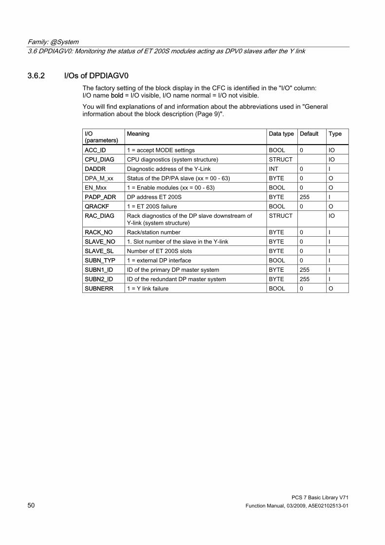
Family: @System 3.6 DPDIAGV0: Monitoring the status of ET 200S modules acting as DPV0 slaves after the Y link
PCS 7 Basic Library V71 50 Function Manual, 03/2009, A5E02102513-01
3.6.2 I/Os of DPDIAGV0 The factory setting of the block display in the CFC is identified in the "I/O" column: I/O name bold = I/O visible, I/O name normal = I/O not visible. You will find explanations of and information about the abbreviations used in "General information about the block description (Page 9)". I/O (parameters)
Meaning Data type Default Type
ACC_ID 1 = accept MODE settings BOOL 0 IO CPU_DIAG CPU diagnostics (system structure) STRUCT IO DADDR Diagnostic address of the Y-Link INT 0 I DPA_M_xx Status of the DP/PA slave (xx = 00 - 63) BYTE 0 O EN_Mxx 1 = Enable modules (xx = 00 - 63) BOOL 0 O PADP_ADR DP address ET 200S BYTE 255 I QRACKF 1 = ET 200S failure BOOL 0 O RAC_DIAG Rack diagnostics of the DP slave downstream of
Y-link (system structure) STRUCT IO
RACK_NO Rack/station number BYTE 0 I SLAVE_NO 1. Slot number of the slave in the Y-link BYTE 0 I SLAVE_SL Number of ET 200S slots BYTE 0 I SUBN_TYP 1 = external DP interface BOOL 0 I SUBN1_ID ID of the primary DP master system BYTE 255 I SUBN2_ID ID of the redundant DP master system BYTE 255 I SUBNERR 1 = Y link failure BOOL 0 O
Family: @System 3.7 DREP: Diagnostic Repeater in the DP master system
PCS 7 Basic Library V71 Function Manual, 03/2009, A5E02102513-01 51
3.7 DREP: Diagnostic Repeater in the DP master system
3.7.1 Description of DREP
Object name (type + number) FB 113 ● DREP block I/Os (Page 56)
Area of application The DREP block evaluates the diagnostic data from a SIMATIC diagnostic repeater for PROFIBUS DP. This repeater must be connected to a DP master.
Calling OBs OB 1 Cyclic processing OB 82 Diagnostic interrupt OB 86 Rack failure OB 100 Restart (warm restart, message initialization)
Use in CFC The following actions are executed automatically with the "Generate module drivers" CFC function: ● Block OB_DIAG1 is installed in the run sequence upstream of the DREP block. ● The following addresses are configured:
– The diagnostic address DADDR of the diagnostics repeater – The geographic address (SUBN_ID and PADP_ADR)
● The following I/Os are interconnected: – The OUT structures CPU_DIAG of the OB_BEGIN block and RAC_DIAG of the
OB_DIAG1 block with the IN_OUT structures of the same name of the DREP block. – The EN input with the output of an AND block. – The inputs of the AND block with the EN_SUBx outputs (x = number of the DP master
system) of the OB_BEGIN block, with EN_Rxxx (xxx = rack/station number) of the SUBNET block and with EN_F of the OB_DIAG1 block.
– EN_DIAG with the EN_DIAG output of the OB_DIAG1 block.

Family: @System 3.7 DREP: Diagnostic Repeater in the DP master system
PCS 7 Basic Library V71 52 Function Manual, 03/2009, A5E02102513-01
Function and operating principle The diagnostics repeater is assigned the following tasks: ● Diagnostics function for two PROFIBUS segments (DP2 and DP3):
The diagnostics function returns the location and cause of line faults, e.g. wire break or missing terminating resistors. The error location is output, including a reference to the relevant nodes, e.g., "Short-circuit to shielding at signal line A, node 12 <-> 13".
● Repeater function for three PROFIBUS segments (DP1, DP2, DP3): The diagnostics repeater amplifies data signals on the bus and interconnects the relevant RS-485 segments.
● Galvanic/electrical isolation of the PG interface from other bus segments: Even if the system is operating at higher transmission rates, interference due to the removal or connection of PG cables is not to be expected at the other PROFIBUS DP segments.
The manual titled Diagnostic Repeaters for PROFIBUS DP contains information about the structure of line error states at the DP1, DP2 and DP3 segments and describes the PG interface. Block DREP reports only the diagnostic events at segments DP2 and DP3 of the diagnostic repeater. Events of the DP1 segment are reported as general "Cable disturbance" group error. The PG interface is not evaluated and does not result in a message. Failure and return of the diagnostics repeater are detected by the upstream block OB_DIAG1 and passed on to the block to report "DR failure". If an error occurs, an incoming "line error" group message is generated for each segment (DP2 or DP3) when a diagnostic repeater detects the error event (bits in the diagnostic message frame indicating the cause of error): Bit Description A.0 1: The location and cause of the error cannot be identified (possibly electromagnetic
interference) A.1 CPU redundancy loss A.2 1: - - A.3 1: Further measurement circuits at the segment, the other diagnostic repeater is connected
with its segment DP2 A.4 1: Further measurement circuits at the segment, the other diagnostic repeater is connected
with its segment DP3 A.5 1: - - A.6 1: Indefinite error cause A.7 1: Critical message frame error rate

Family: @System 3.7 DREP: Diagnostic Repeater in the DP master system
PCS 7 Basic Library V71 Function Manual, 03/2009, A5E02102513-01 53
Bit Description B.0 1:- -. B.1 1: - - B.2 1: - - B.3 1: - - B.4 1: - -. B.5 1: - - B.6 1: - -. B.7 1: - - C.0 1: Segment automatically switched off due to continuous zero level on the line. C.1 1: Segment automatically switched off due to constantly fluctuating line levels. C.2 1: - - C.3 1: - - C.4 1: More than 32 nodes connected to the measurement segment. C.5 1: The distance between the node and the diagnostic repeater exceeds the permitted
line length. C.6 1: The maximum permitted number of diagnostic repeaters connected in series has been
exceeded. C.7 1: - -
The outgoing message will be generated when all segment bits are equal to zero. Call HW Config to analyze details of events output by the diagnostic repeater. An appropriate incoming/outgoing message is going to be generated for the segments (DP2 or DP3) as a result of the following events recognized by a diagnostics repeater: Bit Description A.0 1: - A.1 1:- A.2 1: - A.3 1: - A.4 1: - A.5 1: - A.6 1: - A.7 1: B.0 1: Wire break on signal line A. B.1 1: Short-circuit to shield on signal line B. B.2 1: - B.3 1: Short-circuit to shield on signal line A. B.4 1: Wire break on signal line B. B.5 1: - B.6 1: Wire break on signal line A and/or B, or the terminating resistor is missing. B.7 1: Short-circuit between signal line A and/or B, or an additional terminating resistor
has been installed.

Family: @System 3.7 DREP: Diagnostic Repeater in the DP master system
PCS 7 Basic Library V71 54 Function Manual, 03/2009, A5E02102513-01
Bit Description C.0 1: - C.1 1: - C.2 1: - C.3 1: - C.4 1: - C.5 1: -. C.6 1: - C.7 1: -
Events detected by the diagnostics repeater are acquired synchronously in OB 82. Diagnostic event data is fetched via SFB 54 in the OB_BEGIN block and written to the structure DINFO. The function always sets just one bit to indicate the cause of an event-entering state. Bit C7 may also be set, if the diagnostics repeater has detected further errors. In this case, all previously reported events will be queued. DREP generates a corresponding group error message via ALARM_8P. Flutter messages may develop especially due to error events A.0.1 and A.6.1. They are suppressed as follows : After an outgoing message, a new outgoing message will be delayed by the time in [s] set at the DELAY parameter. If a further error is queued, the outgoing message will not be generated until this error has been reported outgoing.
Error handling The block evaluates the error information of ALARM_8P and writes it to the corresponding output parameters. You will find additional information in the "Error information for output parameter MSG_STAT (Page 322)" section. The block reports a diagnostic error if an error occurs while reading the diagnostic data, or if any other fault corrupts diagnostic data.
Startup characteristics ALARM_8P messages are initialized by the DREP block. This uses SFC13 (DPNRM_DG) to read the latest diagnostic information from the diagnostic repeater.
Overload behavior The interconnected OB_DIAG1 locks the call of DREP for diagnostics if an overload has occurred.
Dynamic response: Not available
Family: @System 3.7 DREP: Diagnostic Repeater in the DP master system
PCS 7 Basic Library V71 Function Manual, 03/2009, A5E02102513-01 55
Message response: The multiple instance ALARM_8P are only called if a message is to be output by this instance. It is only at this point that previously acknowledged messages are updated by the corresponding ALARM block. If the connection to WinCC is down, each ALARM_8P instance can hold up to two message statuses of its event ID. (Usually two messages maximum). Fluuter messages can be suppressed via the DELAY input. The block generates the messages listed below: OB no. Start Event Message 1 Cyclic processing Call of ALARM_8P due to incomplete transfer or unacknowledged
message 82 Diagnostic interrupt Group error message 100 Restart Initialization of ALARM_8P
Operating and monitoring Note: If you have selected the "Enable operator control and monitoring" option in the block object properties in the CFC, the variables transferred to the OS are identified under "I/Os of ..." (OCM column, "+"). Default: Option not activated. If asset management is used in the project and the diagnostic screens have been generated, then the faceplate can be called via its block icon. ● Asset management faceplates (Page 284) ● Asset management faceplates (Page 286)
Additional information For further information, refer to the sections: Message texts and associated values of DREP (Page 57) Maintenance status of MS (Page 326)

Family: @System 3.7 DREP: Diagnostic Repeater in the DP master system
PCS 7 Basic Library V71 56 Function Manual, 03/2009, A5E02102513-01
3.7.2 I/Os of DREP The factory setting of the block display in CFC is identified in the "I/O" column: I/O namebold = I/O visible, I/O name normal = I/O not visible. You will find explanations of and information about the abbreviations used in "General information about the block description (Page 9)". I/O (parameters)
Meaning Type Default Type O&M
ACC_MODE 1 = accept MODE settings BOOL 0 IO CPU_DIAG CPU diagnostics STRUCT IO DADDR Diagnostic address of the diagnostic repeater INT 0 I DELAY Interrupt delay (s) INT 2 I DINFO Diagnostic information from the diagnostic
repeater STRUCT O
EN_DIAG 1 = Queued diagnostic event BOOL 0 I EN_MSG 1 = enable message BOOL 1 I EV_IDx Message number DWORD 0 I MS Maintenance status DWORD 0 I + MSG_ACKx Message acknowledgement WORD 0 O MSG_STATx Message error information WORD 0 O O_MS Maintenance status DWORD 0 O PADP_ADR DP/PA address of the diagnostic repeater BYTE 255 I QDREPF 1 = Removed/faulty diagnostic repeater BOOL 0 O QERR 1 = program error BOOL 1 O RAC_DIAG OB_DIAG1 diagnostics STRUCT IO SUBN_ID DP master system ID BYTE 255 I
Additional information For further information, refer to the sections: Message texts and associated values of DREP (Page 57) Maintenance status of MS (Page 326)

Family: @System 3.7 DREP: Diagnostic Repeater in the DP master system
PCS 7 Basic Library V71 Function Manual, 03/2009, A5E02102513-01 57
3.7.3 Message Texts and Associated Values of DREP
Assignment of message text and message class (Page 324) Message block ALARM_8P
Message no. Default message text Message class
1 DR @1%d@/@2%d@/ Segment DP2: Line fault S 2 DR @1%d@/@2%d@/DP2:
@5%d@.@6%d@m/wire break A /@3%d@ @4%d@
S
3 DR @1%d@/@2%d@/DP2: @5%d@.@6%d@m/short A/@3%d@ @4%d@
S
4 DR @1%d@/@2%d@/DP2: @5%d@.@6%d@m/wire break B/@3%d@ @4%d@
S
5 DR @1%d@/@2%d@/DP2: @5%d@.@6%d@m/short B/@3%d@ @4%d@
S
6 DR @1%d@/@2%d@/DP2: @5%d@.@6%d@m/wire break AB or terminating resistor missing/@3%d@ @4%d@
S
7 DR @1%d@/@2%d@/DP2: @5%d@.@6%d@m/short AB or too many terminating resistors/@3%d@ @4%d@
S
EV_ID1
8 DR @1%d@/@2%d@/ segment DP1: Line fault S 1 DR @1%d@/@2%d@/ segment DP3: Line fault S 2 DR @1%d@/@2%d@/DP3:
@5%d@.@6%d@m/wire break A /@3%d@ @4%d@
S
3 DR @1%d@/@2%d@/DP3: @5%d@.@6%d@m/short A/@3%d@ @4%d@
S
4 DR @1%d@/@2%d@/DP3: @5%d@.@6%d@m/wire break B/@3%d@ @4%d@
S
5 DR @1%d@/@2%d@/DP3: @5%d@.@6%d@m/short B/@3%d@ @4%d@
S
6 DR @1%d@/@2%d@/DP3: @5%d@.@6%d@m/wire break AB or terminating resistor missing/@3%d@ @4%d@
S
7 DR @1%d@/@2%d@/DP3: @5%d@.@6%d@m/short AB or too many terminating resistors/@3%d@ @4%d@
S
EV_ID2
8 DR @1%d@/@2%d@: @7W%t#DREP_TXT@ S
You will find the message texts and their text numbers in "Text library for DREP (Page 336)".
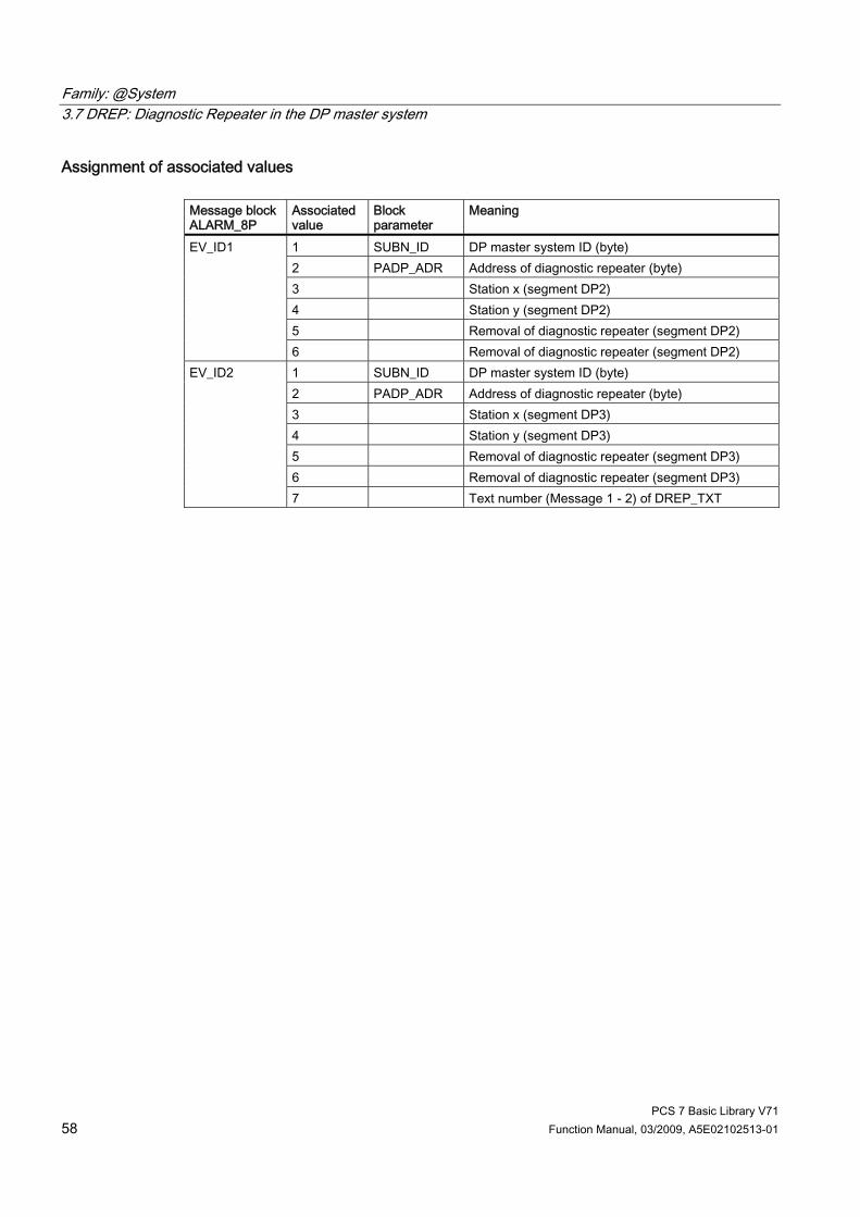
Family: @System 3.7 DREP: Diagnostic Repeater in the DP master system
PCS 7 Basic Library V71 58 Function Manual, 03/2009, A5E02102513-01
Assignment of associated values Message block ALARM_8P
Associatedvalue
Block parameter
Meaning
1 SUBN_ID DP master system ID (byte) 2 PADP_ADR Address of diagnostic repeater (byte) 3 Station x (segment DP2) 4 Station y (segment DP2) 5 Removal of diagnostic repeater (segment DP2)
EV_ID1
6 Removal of diagnostic repeater (segment DP2) 1 SUBN_ID DP master system ID (byte) 2 PADP_ADR Address of diagnostic repeater (byte) 3 Station x (segment DP3) 4 Station y (segment DP3) 5 Removal of diagnostic repeater (segment DP3) 6 Removal of diagnostic repeater (segment DP3)
EV_ID2
7 Text number (Message 1 - 2) of DREP_TXT

Family: @System 3.8 DREP_L: Diagnostic Repeater downstream of a Y-Link
PCS 7 Basic Library V71 Function Manual, 03/2009, A5E02102513-01 59
3.8 DREP_L: Diagnostic Repeater downstream of a Y-Link
3.8.1 Description of DREP_L
Object name (type + number) FB 125 ● DREP_L Block I/Os (Page 64)
Area of application The DREP_L block evaluates diagnostic data from a SIMATIC diagnostic repeater for PROFIBUS DP. The diagnostic repeater (after DPV0) must be connected downstream of a Y-Link (after DPV1).
Calling OBs OB 1 Cyclic processing OB 82 Diagnostic interrupt OB 86 Rack failure OB 100 Restart (warm start) (startup, message initialization)
Use in CFC The following actions are executed automatically with the "Generate module drivers" CFC function: ● The OB_DIAG1 block is integrated into the run sequence upstream of DREP_L. ● The following addresses are configured:
– The diagnostic address of the DP/PA link (DADDR) is connected downstream of the diagnostic repeater
– The geographical address (SUBN1_ID, SUBN2_ID, RACK_NO and PADP_ADR) ● The following I/Os are interconnected:
– The OUT structures CPU_DIAG of the OB_BEGIN block and RAC_DIAG of the OB_DIAG1 block with the DREP_L INOUT structures of the same name.
– The EN input is interconnected with the output of an AND block. The inputs of the AND block with the EN_SUBx outputs (x = number of the DP master system) of the OB_BEGIN block, with EN_Rxxx (xxx = rack/station number) of the SUBNET block, and with EN_F of the OB_DIAG1 block.
– EN_DIAG with the EN_DIAG output of the OB_DIAG1 block.
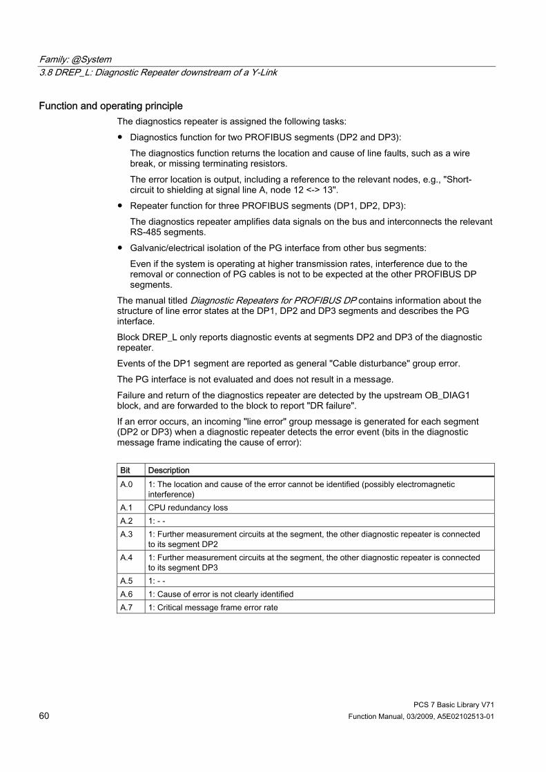
Family: @System 3.8 DREP_L: Diagnostic Repeater downstream of a Y-Link
PCS 7 Basic Library V71 60 Function Manual, 03/2009, A5E02102513-01
Function and operating principle The diagnostics repeater is assigned the following tasks: ● Diagnostics function for two PROFIBUS segments (DP2 and DP3):
The diagnostics function returns the location and cause of line faults, such as a wire break, or missing terminating resistors. The error location is output, including a reference to the relevant nodes, e.g., "Short-circuit to shielding at signal line A, node 12 <-> 13".
● Repeater function for three PROFIBUS segments (DP1, DP2, DP3): The diagnostics repeater amplifies data signals on the bus and interconnects the relevant RS-485 segments.
● Galvanic/electrical isolation of the PG interface from other bus segments: Even if the system is operating at higher transmission rates, interference due to the removal or connection of PG cables is not to be expected at the other PROFIBUS DP segments.
The manual titled Diagnostic Repeaters for PROFIBUS DP contains information about the structure of line error states at the DP1, DP2 and DP3 segments and describes the PG interface. Block DREP_L only reports diagnostic events at segments DP2 and DP3 of the diagnostic repeater. Events of the DP1 segment are reported as general "Cable disturbance" group error. The PG interface is not evaluated and does not result in a message. Failure and return of the diagnostics repeater are detected by the upstream OB_DIAG1 block, and are forwarded to the block to report "DR failure". If an error occurs, an incoming "line error" group message is generated for each segment (DP2 or DP3) when a diagnostic repeater detects the error event (bits in the diagnostic message frame indicating the cause of error): Bit Description A.0 1: The location and cause of the error cannot be identified (possibly electromagnetic
interference) A.1 CPU redundancy loss A.2 1: - - A.3 1: Further measurement circuits at the segment, the other diagnostic repeater is connected
to its segment DP2 A.4 1: Further measurement circuits at the segment, the other diagnostic repeater is connected
to its segment DP3 A.5 1: - - A.6 1: Cause of error is not clearly identified A.7 1: Critical message frame error rate

Family: @System 3.8 DREP_L: Diagnostic Repeater downstream of a Y-Link
PCS 7 Basic Library V71 Function Manual, 03/2009, A5E02102513-01 61
Bit Description B.0 1: B.1 1: B.2 1: - - B.3 1: B.4 1: B.5 1: - - B.6 1: B.7 1: C.0 1: Segment automatically switched off due to continuous zero level on the line. C.1 1: Segment automatically switched off due to constantly fluctuating line levels. C.2 1: - - C.3 1: - - C.4 1: More than 32 nodes connected to the measurement segment C.5 1: The distance between the node and the diagnostic repeater exceeds the permitted
line length C.6 1: The maximum permitted number of diagnostic repeaters connected in series has been
exceeded C.7 1: - -
The outgoing message will be generated when all segment bits are equal to zero. Call HW Config to analyze details of events output by the diagnostic repeater. An appropriate incoming/outgoing message will be generated for each segment (DP2 or DP3) in response to the following events detected by a diagnostic repeater: Bit Description A.0 1: - A.1 1:- A.2 1: - A.3 1: - A.4 1: - A.5 1: - A.6 1: - A.7 1: B.0 1: Wire break at signal line A B.1 1: Short-circuit to shielding at signal line B B.2 1: - B.3 1: Short-circuit to shielding at signal line A B.4 1: Wire break at signal line B B.5 1: - B.6 1: Wire break at signal line A and/or B, or the terminating resistor is missing B.7 1: Short-circuit signal line A <-> B, or an additional terminating resistor has been
installed
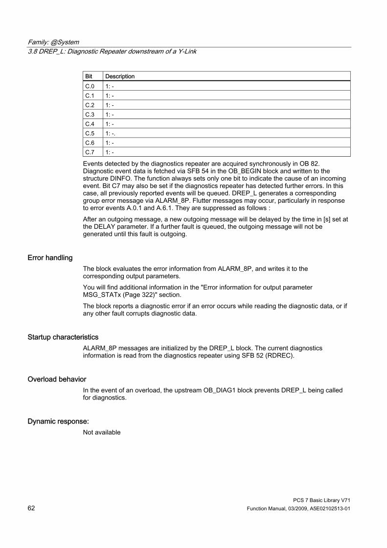
Family: @System 3.8 DREP_L: Diagnostic Repeater downstream of a Y-Link
PCS 7 Basic Library V71 62 Function Manual, 03/2009, A5E02102513-01
Bit Description C.0 1: - C.1 1: - C.2 1: - C.3 1: - C.4 1: - C.5 1: -. C.6 1: - C.7 1: -
Events detected by the diagnostics repeater are acquired synchronously in OB 82. Diagnostic event data is fetched via SFB 54 in the OB_BEGIN block and written to the structure DINFO. The function always sets only one bit to indicate the cause of an incoming event. Bit C7 may also be set if the diagnostics repeater has detected further errors. In this case, all previously reported events will be queued. DREP_L generates a corresponding group error message via ALARM_8P. Flutter messages may occur, particularly in response to error events A.0.1 and A.6.1. They are suppressed as follows : After an outgoing message, a new outgoing message will be delayed by the time in [s] set at the DELAY parameter. If a further fault is queued, the outgoing message will not be generated until this fault is outgoing.
Error handling The block evaluates the error information from ALARM_8P, and writes it to the corresponding output parameters. You will find additional information in the "Error information for output parameter MSG_STATx (Page 322)" section. The block reports a diagnostic error if an error occurs while reading the diagnostic data, or if any other fault corrupts diagnostic data.
Startup characteristics ALARM_8P messages are initialized by the DREP_L block. The current diagnostics information is read from the diagnostics repeater using SFB 52 (RDREC).
Overload behavior In the event of an overload, the upstream OB_DIAG1 block prevents DREP_L being called for diagnostics.
Dynamic response: Not available

Family: @System 3.8 DREP_L: Diagnostic Repeater downstream of a Y-Link
PCS 7 Basic Library V71 Function Manual, 03/2009, A5E02102513-01 63
Message response: The multiple instance ALARM_8P are only called if a message is to be output by this instance. It is only at this point that previously acknowledged messages are updated by the corresponding ALARM block. If the connection to WinCC is down, each ALARM_8P instance can hold up to two message statuses of its event ID. Flutter messages can be suppressed via the DELAY input. The block generates the messages listed below: OB no. Start Event Message 1 Cyclic processing Call of ALARM_8P due to incomplete transfer or unacknowledged
message 82 Diagnostic interrupt Group error message 100 Restart Initialization of ALARM_8P
Operating and monitoring Note: If you selected the "OCM possible" option in the block object properties in the CFC, the variables transferred to the OS are identified under "I/Os of ..." (OCM column, "+"). Default: Option not activated. If asset management is used in the project, and the diagnostic screens were generated, the faceplate can be called via its block icon. ● Asset management block icons (Page 284) ● Asset management faceplates (Page 286)
Additional information For further information, refer to the following sections: Message Texts and associated values of DREP_L (Page 65) Maintenance status of MS (Page 326)

Family: @System 3.8 DREP_L: Diagnostic Repeater downstream of a Y-Link
PCS 7 Basic Library V71 64 Function Manual, 03/2009, A5E02102513-01
3.8.2 I/Os of DREP_L The factory setting of the block display in CFC is identified in the "I/O" column: I/O namebold = I/O visible, I/O name normal = I/O not visible. You will find explanations of and information about the abbreviations used in "General information about the block description (Page 9)". I/O (parameters)
Meaning Type Default
Type O&M
ACC_MODE 1 = accept MODE settings BOOL 0 IO CPU_DIAG CPU diagnostics STRUCT IO DADDR Diagnostic address of the DP/PA link INT 0 I DELAY Interrupt delay (s) INT 2 I DINFO Diagnostic information from the diagnostic
repeater STRUCT O
EN_DIAG 1 = Queued diagnostic event BOOL 0 I EN_MSG 1 = enable message BOOL 1 I EV_IDx Message number DWORD 0 I MS Maintenance status DWORD 0 I + MSG_ACKx Message acknowledgement WORD 0 O MSG_STATx Message error information WORD 0 O O_MS Maintenance status DWORD 0 O PADP_ADR DP/PA address of the diagnostic repeater BYTE 255 I QDREPF 1 = Removed/faulty diagnostic repeater BOOL 0 O QERR 1 = program error BOOL 1 O RAC_DIAG OB_DIAG1 diagnostics STRUCT IO RACK_NO Rack number BYTE 255 I SUBN1_ID ID of the primary DP master system BYTE 255 I SUBN2_ID ID of the redundant DP master system BYTE 255 I
Additional information For further information, refer to the following sections: Message texts and associated values of DREP_L (Page 65) Maintenance status of MS (Page 326)
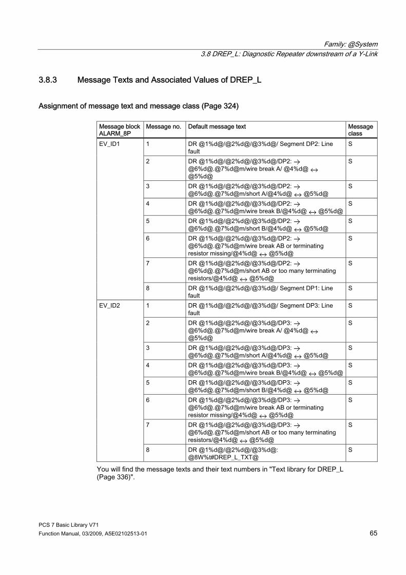
Family: @System 3.8 DREP_L: Diagnostic Repeater downstream of a Y-Link
PCS 7 Basic Library V71 Function Manual, 03/2009, A5E02102513-01 65
3.8.3 Message Texts and Associated Values of DREP_L
Assignment of message text and message class (Page 324) Message block ALARM_8P
Message no. Default message text Message class
1 DR @1%d@/@2%d@/@3%d@/ Segment DP2: Line fault
S
2 DR @1%d@/@2%d@/@3%d@/DP2: @6%d@.@7%d@m/wire break A/ @4%d@ @5%d@
S
3 DR @1%d@/@2%d@/@3%d@/DP2: @6%d@.@7%d@m/short A/@4%d@ @5%d@
S
4 DR @1%d@/@2%d@/@3%d@/DP2: @6%d@.@7%d@m/wire break B/@4%d@ @5%d@
S
5 DR @1%d@/@2%d@/@3%d@/DP2: @6%d@.@7%d@m/short B/@4%d@ @5%d@
S
6 DR @1%d@/@2%d@/@3%d@/DP2: @6%d@.@7%d@m/wire break AB or terminating resistor missing/@4%d@ @5%d@
S
7 DR @1%d@/@2%d@/@3%d@/DP2: @6%d@.@7%d@m/short AB or too many terminating resistors/@4%d@ @5%d@
S
EV_ID1
8 DR @1%d@/@2%d@/@3%d@/ Segment DP1: Line fault
S
1 DR @1%d@/@2%d@/@3%d@/ Segment DP3: Line fault
S
2 DR @1%d@/@2%d@/@3%d@/DP3: @6%d@.@7%d@m/wire break A/ @4%d@ @5%d@
S
3 DR @1%d@/@2%d@/@3%d@/DP3: @6%d@.@7%d@m/short A/@4%d@ @5%d@
S
4 DR @1%d@/@2%d@/@3%d@/DP3: @6%d@.@7%d@m/wire break B/@4%d@ @5%d@
S
5 DR @1%d@/@2%d@/@3%d@/DP3: @6%d@.@7%d@m/short B/@4%d@ @5%d@
S
6 DR @1%d@/@2%d@/@3%d@/DP3: @6%d@.@7%d@m/wire break AB or terminating resistor missing/@4%d@ @5%d@
S
7 DR @1%d@/@2%d@/@3%d@/DP3: @6%d@.@7%d@m/short AB or too many terminating resistors/@4%d@ @5%d@
S
EV_ID2
8 DR @1%d@/@2%d@/@3%d@: @8W%t#DREP_L_TXT@
S
You will find the message texts and their text numbers in "Text library for DREP_L (Page 336)".
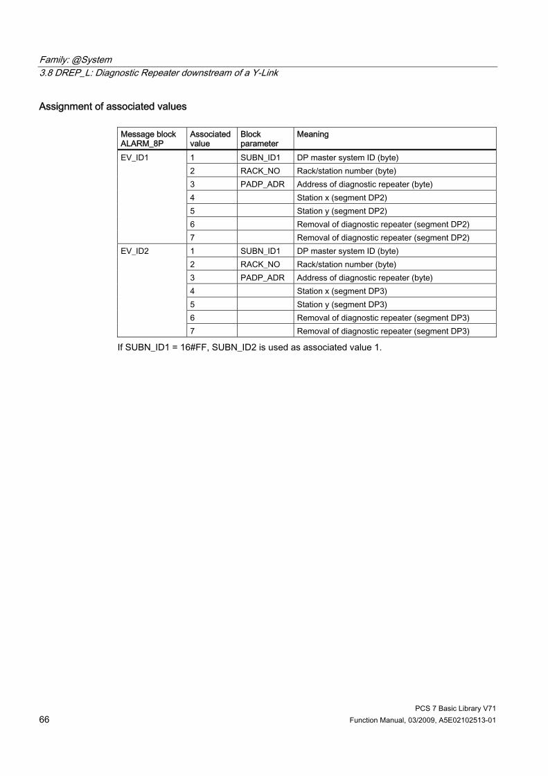
Family: @System 3.8 DREP_L: Diagnostic Repeater downstream of a Y-Link
PCS 7 Basic Library V71 66 Function Manual, 03/2009, A5E02102513-01
Assignment of associated values Message block ALARM_8P
Associated value
Block parameter
Meaning
1 SUBN_ID1 DP master system ID (byte) 2 RACK_NO Rack/station number (byte) 3 PADP_ADR Address of diagnostic repeater (byte) 4 Station x (segment DP2) 5 Station y (segment DP2) 6 Removal of diagnostic repeater (segment DP2)
EV_ID1
7 Removal of diagnostic repeater (segment DP2) 1 SUBN_ID1 DP master system ID (byte) 2 RACK_NO Rack/station number (byte) 3 PADP_ADR Address of diagnostic repeater (byte) 4 Station x (segment DP3) 5 Station y (segment DP3) 6 Removal of diagnostic repeater (segment DP3)
EV_ID2
7 Removal of diagnostic repeater (segment DP3)
If SUBN_ID1 = 16#FF, SUBN_ID2 is used as associated value 1.

Family: @System 3.9 FM_CNT: Programming and controlling FM 350 modules
PCS 7 Basic Library V71 Function Manual, 03/2009, A5E02102513-01 67
3.9 FM_CNT: Programming and controlling FM 350 modules
3.9.1 Description of FM_CNT
Object name (type + number) FB 126 ● FM_CNT Block I/Os (Page 71)
Area of application Block FM_CNT is used to configure and control FM 350-1 and FM 350-2 modules. It writes the counter levels, limits and comparison values of the FM 350-2 module.
Calling OBs OB 100 and the cyclic OB (100 ms recommended) used for transmitting data. Also note the assignments (Page 325) to the FM_CO block.
Use in the CFC The following actions are executed automatically with the "Generate module drivers" CFC function: ● The block is installed in the cyclic OB upstream of the CH_CNT blocks. ● The block runtime group is installed in OB 100 downstream of MOD_D1. ● The LADDR, FM_MODE, RACK_NO, SUBN1_ID, SUBN2_ID, and SLOT_NO inputs are
configured. ● The MODEx inputs are interconnected with the OMODEx outputs of the MOD_D1 block. ● The FM_DATA output structure is interconnected with the structure of the same name of
the CH_CNT block. ● The OMODEx output is interconnected with the MODE input of the CH_CNT block. ● The OUT structure CPU_DIAG of OB_BEGIN is interconnected with the IN_OUT structure
of the same name of FM_CNT. ● The EN_CO input structure is interconnected with the EN_CO_x output structure of the
FM_CO block (x = number of the rack). ● The output ENCO is connected to the input ENCOx_yy of the FM_CO block (x = number
of the rack, yy = coordination number).
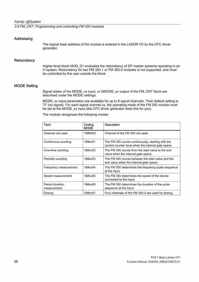
Family: @System 3.9 FM_CNT: Programming and controlling FM 350 modules
PCS 7 Basic Library V71 68 Function Manual, 03/2009, A5E02102513-01
Addressing The logical base address of the module is entered in the LADDR I/O by the CFC driver generator.
Redundancy Higher-level block MOD_D1 evaluates the redundancy of DP master systems operating in an H system. Redundancy for two FM 350-1 or FM 350-2 modules is not supported, and must be controlled by the user outside the block.
MODE Setting Signal states of the MODE_xx input, or QMODE_xx output of the FM_CNT block are described under the MODE settings. MODE_xx input parameters are available for up to 8 signal channels. Their default setting is "0" (no signal). For each signal channel xx, the operating mode of the FM 350 module must be set at the MODE_xx input (the CFC driver generator does this for you). The module recognizes the following modes: Term Coding
MODE Description
Channel not used 16#0000 Channel of the FM 350 not used.
Continuous counting 16#xx01 The FM 350 counts continuously, starting with the current counter level when the internal gate opens.
One-time counting 16#xx02 The FM 350 counts from the start value to the end value when the internal gate opens.
Periodic counting 16#xx03 The FM 350 counts between the start value and the end value when the internal gate opens.
Frequency measurement 16#xx04 The FM 350 determines the frequency pulse sequence at the input.
Speed measurement 16#xx05 The FM 350 determines the speed of the device connected to the input.
Period duration measurement
16#xx06 The FM 350 determines the duration of the pulse sequence at the input.
Dosing 16#xx07 Four channels of the FM 350-2 are used for dosing.

Family: @System 3.9 FM_CNT: Programming and controlling FM 350 modules
PCS 7 Basic Library V71 Function Manual, 03/2009, A5E02102513-01 69
The count and measured values can be recorded for the FM 350-2 module, either via the process image(fast update) or via "Read data record" (slower update). If the count and measured value of a channel are made available in the process image, they must be aligned in the process image. The following variants are possible. Term Coding
MODE Description
Count and measured value are not in the process image
16#Cxxx Read count and measured values via data record
Only the count value is in the process image
16#8xxx Read measured value via data record and count value in the process image
Only the measured value is in the process image
16#4xxx Read count values via data record and measured value in the process image
Count and measured value are in the process image
16#0xxx Read count and measured value in the process image
Data type DWORD count and measured value
16#x0xx Count value before measured value, both of the data type DWORD
Data type WORD count value 16#x1xx Count value of the the data type WORD before measured value of the data type DWORD
Data type WORD measured value 16#x2xx Count value of the data type DWORD before measured value of the data type WORD
Data type WORD count and measured value
16#x3xx Count value before measured value, both of the data type WORD
Data type DWORD count and measured value
16#x8xx Measured value before count value, both of the data type DWORD
Data type WORD count value 16#x9xx Measured value of the the data type DWORD before count value of the data type WORD
Data type WORD measured value 16#xAxx Measured value of the the data type WORD before count value of the data type DWORD
Data type WORD count and measured value
16#xBx Measured value before count value, both of the data type WORD
MODE is formed by the linking the operating mode code, and the access type value. Example: Count and measured value in "Dosing" mode of the the data type DWORD is not in the process image MODE = 16#C007.
Error handling The plausibility of input parameters is not checked.
Startup characteristics Whenever the system or FM 350-1/FM 350-2 starts up, the block coordinates the restart with the module. The CMP_VALx parameters are then loaded into the FM 350. ALARM_8P is initialized.
Overload behavior Not available

Family: @System 3.9 FM_CNT: Programming and controlling FM 350 modules
PCS 7 Basic Library V71 70 Function Manual, 03/2009, A5E02102513-01
Time response Not available
Message functionality The block reports operating and data errors for the FM 350-1 module, and data errors for FM 350-2 using ALARM_8P. The message function can be disabled by setting EN_MSG = FALSE. The MOD_D1 block reports diagnostic interrupts from the FM 350-1 or FM 350-2.
Operating and monitoring The block has no faceplate. Note: If you selected the "OCM possible" option in the block object properties in the CFC, the variables transferred to the OS are identified under "I/Os of ..." (OCM column, "+"). Default: Option not activated.
Additional information You will find more information in: Message texts and associated values of FM_CNT (Page 72)
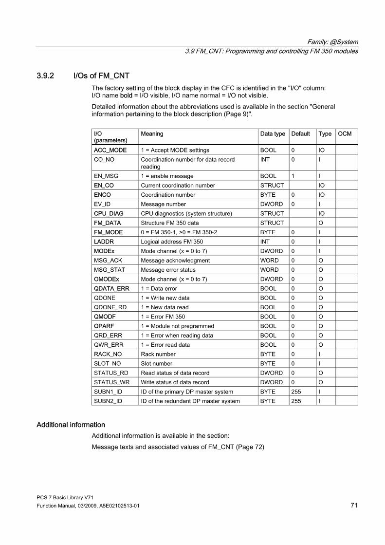
Family: @System 3.9 FM_CNT: Programming and controlling FM 350 modules
PCS 7 Basic Library V71 Function Manual, 03/2009, A5E02102513-01 71
3.9.2 I/Os of FM_CNT The factory setting of the block display in the CFC is identified in the "I/O" column: I/O name bold = I/O visible, I/O name normal = I/O not visible. Detailed information about the abbreviations used is available in the section "General information pertaining to the block description (Page 9)". I/O (parameters)
Meaning Data type Default
Type OCM
ACC_MODE 1 = Accept MODE settings BOOL 0 IO CO_NO Coordination number for data record
reading INT 0 I
EN_MSG 1 = enable message BOOL 1 I EN_CO Current coordination number STRUCT IO ENCO Coordination number BYTE 0 IO EV_ID Message number DWORD 0 I CPU_DIAG CPU diagnostics (system structure) STRUCT IO FM_DATA Structure FM 350 data STRUCT O FM_MODE 0 = FM 350-1, >0 = FM 350-2 BYTE 0 I LADDR Logical address FM 350 INT 0 I MODEx Mode channel (x = 0 to 7) DWORD 0 I MSG_ACK Message acknowledgment WORD 0 O MSG_STAT Message error status WORD 0 O OMODEx Mode channel (x = 0 to 7) DWORD 0 O QDATA_ERR 1 = Data error BOOL 0 O QDONE 1 = Write new data BOOL 0 O QDONE_RD 1 = New data read BOOL 0 O QMODF 1 = Error FM 350 BOOL 0 O QPARF 1 = Module not pregrammed BOOL 0 O QRD_ERR 1 = Error when reading data BOOL 0 O QWR_ERR 1 = Error read data BOOL 0 O RACK_NO Rack number BYTE 0 I SLOT_NO Slot number BYTE 0 I STATUS_RD Read status of data record DWORD 0 O STATUS_WR Write status of data record DWORD 0 O SUBN1_ID ID of the primary DP master system BYTE 255 I SUBN2_ID ID of the redundant DP master system BYTE 255 I
Additional information Additional information is available in the section: Message texts and associated values of FM_CNT (Page 72)
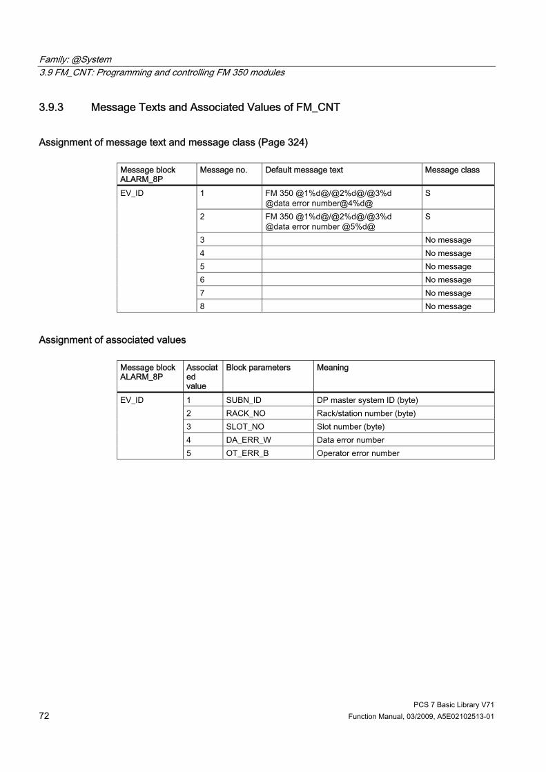
Family: @System 3.9 FM_CNT: Programming and controlling FM 350 modules
PCS 7 Basic Library V71 72 Function Manual, 03/2009, A5E02102513-01
3.9.3 Message Texts and Associated Values of FM_CNT
Assignment of message text and message class (Page 324) Message block ALARM_8P
Message no. Default message text Message class
1 FM 350 @1%d@/@2%d@/@3%d @data error number@4%d@
S
2 FM 350 @1%d@/@2%d@/@3%d @data error number @5%d@
S
3 No message 4 No message 5 No message 6 No message 7 No message
EV_ID
8 No message
Assignment of associated values Message block ALARM_8P
Associated value
Block parameters Meaning
1 SUBN_ID DP master system ID (byte) 2 RACK_NO Rack/station number (byte) 3 SLOT_NO Slot number (byte) 4 DA_ERR_W Data error number
EV_ID
5 OT_ERR_B Operator error number
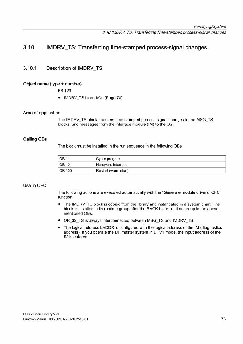
Family: @System 3.10 IMDRV_TS: Transferring time-stamped process-signal changes
PCS 7 Basic Library V71 Function Manual, 03/2009, A5E02102513-01 73
3.10 IMDRV_TS: Transferring time-stamped process-signal changes
3.10.1 Description of IMDRV_TS
Object name (type + number) FB 129 ● IMDRV_TS block I/Os (Page 78)
Area of application The IMDRV_TS block transfers time-stamped process signal changes to the MSG_TS blocks, and messages from the interface module (IM) to the OS.
Calling OBs The block must be installed in the run sequence in the following OBs: OB 1 Cyclic program OB 40 Hardware interrupt OB 100 Restart (warm start)
Use in CFC The following actions are executed automatically with the "Generate module drivers" CFC function: ● The IMDRV_TS block is copied from the library and instantiated in a system chart. The
block is installed in its runtime group after the RACK block runtime group in the above-mentioned OBs.
● OR_32_TS is always interconnected between MSG_TS and IMDRV_TS. ● The logical address LADDR is configured with the logical address of the IM (diagnostics
address). If you operate the DP master system in DPV1 mode, the input address of the IM is entered.

Family: @System 3.10 IMDRV_TS: Transferring time-stamped process-signal changes
PCS 7 Basic Library V71 74 Function Manual, 03/2009, A5E02102513-01
● The RAC_DIAG structure of the RACK block is interconnected with the structure of the same name of the IMDRV_TS block.
● The S_CH_xxx and TINF_xxx inputs of the TRIG_INF structure are set. Every signal that is time-stamped by the IM has a unique assignment identified by the slot of the module combined with the corresponding channel number. There are 128 inputs of the WORD data type for 128 signals. The slot number of the relevant digital input module is entered in the more significant byte and the channel number (signal of the digital input module) is entered into the less significant byte. The slot and channel number of the process signals are entered in the block inputs S_CH_xxx. Example: In HW Config, you have activated time-stamping for the digital signal of channel 10 of a digital input module that is inserted in slot 5 of an ET 200M. The number 16#050A is entered at the first available input S_CH_xxx of the IM_DRV_TS. The information about the edge evaluation for the event entering state is stored in the TINF_xxx parameters of the TRIG_INF structure. 0 means: 0 -> 1 is event entering state 1 means: 1 -> 0 is event entering state.
Description of the functions The IMDRV_TS block reads the messages from the message buffers (up to 15 data records, each with 20 messages) of an IM, and transfers them to a message block for time stamps (MSG_TS). The MSG_TS sends the messages via an ALARM_8P block whose time stamps for its 8 messages are entered in the 1st associated value in an ARRAY of BYTE.
How it works ● Hardware interrupt (OB 40): The IM generates a hardware interrupt if there are new
messages. The time-stamp status, including the number of the IM data record to be fetched and the number of messages in the data record, are fetched from the start information of the process interrupt OB and stored for cyclic processing. The interrupt stack can hold up to 17 process interrupts. If this maximum is exceeded, all new information will be lost. The loss of information is indicated by the "Loss of message at IM (buffer overflow)" message.
● Cyclic processing: If any messages are queued in the stack, SFB 52 (RDREC, read data record) reads the relevant data record (message buffer). If there are several data records to be fetched, it will fetch the record that contains the oldest messages (oldest hardware interrupt). The block instance temporarily stores a maximum of 20 messages of a data record. The IM can enter new messages in a data record once it has been read. If all data records are in use, the IM enters "Loss of message at IM (buffer overflow)" (incoming) as the last message in the message buffer. "Loss of message at IM (buffer overflow)" (outgoing) is then entered as the first message in the first free data record. Messages received within the interval between a buffer overflow and the enabling of a record will be lost. The function compares the slot/channel number of the stored messages with the input parameters of the slot/channel number block (S_CH_xxx). If they match, the message is written to the corresponding output (TS_xxx). Errors occurring during data exchange between the block and IM are reported by the ALARM_8P block (for example, an I/O access error).

Family: @System 3.10 IMDRV_TS: Transferring time-stamped process-signal changes
PCS 7 Basic Library V71 Function Manual, 03/2009, A5E02102513-01 75
Quality code for the time stamp TS_xxx.TS0/TS1 A quality code QC_TS is formed for the time stamp TS0/TS1, and entered in TS_xxx. State Quality code
TS_xxx.QC_TS Valid value 16#80 Invalid value (higher level error) • Time-of-day frame failure • Stop the time stamp function • Message loss on IM (buffer overflow) • Loss of information with redundancy
16#40
Invalid value 16##00
Addressing For general information, see also Addressing (Page 323) The logical address of the IM obtained in HW Config (corresponds to the diagnostic address, or the input address of the IM for a DP master system in DPV1 mode) is entered at the driver's block input (LADDR) by the "Generate module driver" CFC function. Any change to the LADDR block input will initiate a single check of the logical address according to the startup characteristics of the block. Process signals that require a time stamp and are detected via an IM must be configured accordingly in HW Config.
Error handling I/O access error: QPERAF The block could not access the IM. A data record could not be read.
Block processing error: QERR A block execution error has occurred.
Module parameter assignment error: QPARF Faulty block configuration: Incorrect logical basic address entered.
Parameter assignment error: QBPARF Faulty block configuration: The slot/channel number of an IM message does not match
any slot/channel number of the block input parameters.
Rack error: QRACKF Failure of the rack containing the IM or IM failure.

Family: @System 3.10 IMDRV_TS: Transferring time-stamped process-signal changes
PCS 7 Basic Library V71 76 Function Manual, 03/2009, A5E02102513-01
IM Startup Characteristics During startup/restart of the IM, the system will generate process interrupts once again for those records which were occupied prior to restart but had not been fetched. The message "Startup data (incoming)" is entered as the first message of the first free data record. After restart, the system checks all monitored digital signals for changes, outputs a message if appropriate. It finally generates the message "Startup data (outgoing)".
IMDRV_TS driver block startup characteristics Initializes the ALARM_8P blocks using the data stored prior to the CPU transition to STOP. During an initial startup, the signal state is set to "Zero". During startup, the block verifies the existence of an IM at its logical address set in LADDR. If this does not exist, it sets the QPARF output to TRUE, and does not access any I/Os in its subsequent cycles. QPARF = FALSE and I/O access is enabled only after the correct module has been inserted, or the logical address has been set correctly. Stored process interrupt data which were not computed before the restart will be deleted.
Redundancy Time stamping in H systems equipped with two IM units is redundant under the following conditions: ● Both IM units communicate via the communication (K) bus. ● No error has occurred during the update of the active and passive IM. The SUBNET and RACK blocks report loss of redundancy (failure of an IM), separately from the IMDRV_TS block. Time stamping is interrupted for the duration of the changeover between the active and passive IM. This period of interruption is indicated by the message "Redundant changeover" (incoming/outgoing state). The active IM usually reports the current I/O status to the redundant IM. If this communication is disrupted, the message "Loss of information with redundancy" (entering state) is output. When the I/O statuses of the active and redundant IM are synchronized, the message "Loss of information with redundancy" (outgoing) is output.
Family: @System 3.10 IMDRV_TS: Transferring time-stamped process-signal changes
PCS 7 Basic Library V71 Function Manual, 03/2009, A5E02102513-01 77
Time response Not available
Message response The block signals system messages from the IM via the ALARM_8P block. The time-stamped hardware interrupts are forwarded to the MSG_TS IM message block via OR_32_TS.
Operator control and monitoring: The block does not have a faceplate.
Additional information You will find more information in: Message texts of IMDRV_TS (Page 79)
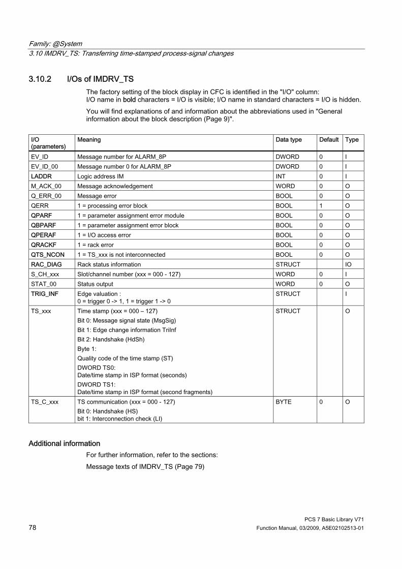
Family: @System 3.10 IMDRV_TS: Transferring time-stamped process-signal changes
PCS 7 Basic Library V71 78 Function Manual, 03/2009, A5E02102513-01
3.10.2 I/Os of IMDRV_TS The factory setting of the block display in CFC is identified in the "I/O" column: I/O name in bold characters = I/O is visible; I/O name in standard characters = I/O is hidden. You will find explanations of and information about the abbreviations used in "General information about the block description (Page 9)".
I/O (parameters)
Meaning Data type Default Type
EV_ID Message number for ALARM_8P DWORD 0 I EV_ID_00 Message number 0 for ALARM_8P DWORD 0 I LADDR Logic address IM INT 0 I M_ACK_00 Message acknowledgement WORD 0 O Q_ERR_00 Message error BOOL 0 O QERR 1 = processing error block BOOL 1 O QPARF 1 = parameter assignment error module BOOL 0 O QBPARF 1 = parameter assignment error block BOOL 0 O QPERAF 1 = I/O access error BOOL 0 O QRACKF 1 = rack error BOOL 0 O QTS_NCON 1 = TS_xxx is not interconnected BOOL 0 O RAC_DIAG Rack status information STRUCT IO S_CH_xxx Slot/channel number (xxx = 000 - 127) WORD 0 I STAT_00 Status output WORD 0 O TRIG_INF Edge valuation :
0 = trigger 0 -> 1, 1 = trigger 1 -> 0 STRUCT I
TS_xxx Time stamp (xxx = 000 – 127) Bit 0: Message signal state (MsgSig) Bit 1: Edge change information TriInf Bit 2: Handshake (HdSh) Byte 1: Quality code of the time stamp (ST) DWORD TS0: Date/time stamp in ISP format (seconds) DWORD TS1: Date/time stamp in ISP format (second fragments)
STRUCT O
TS_C_xxx TS communication (xxx = 000 - 127) Bit 0: Handshake (HS) bit 1: Interconnection check (LI)
BYTE 0 O
Additional information For further information, refer to the sections: Message texts of IMDRV_TS (Page 79)
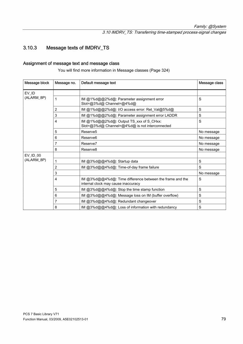
Family: @System 3.10 IMDRV_TS: Transferring time-stamped process-signal changes
PCS 7 Basic Library V71 Function Manual, 03/2009, A5E02102513-01 79
3.10.3 Message texts of IMDRV_TS
Assignment of message text and message class You will find more information in Message classes (Page 324)
Message block
Message no.
Default message text
Message class
1 IM @1%d@@2%d@: Parameter assignment error
Slot=@3%d@ Channel=@4%d@ S
2 IM @1%d@@2%d@: I/O access error: Ret_Val@5%d@ S 3 IM @1%d@@2%d@: Parameter assignment error LADDR S 4 IM @1%d@@2%d@: Output TS_xxx of S_CHxx:
Slot=@3%d@ Channel=@4%d@ is not interconnected S
5 Reserve5 No message 6 Reserve6 No message 7 Reserve7 No message
EV_ID (ALARM_8P)
8 Reserve8 No message 1 IM @3%d@@4%d@: Startup data S 2 IM @3%d@@4%d@: Time-of-day frame failure S 3 No message 4 IM @3%d@@4%d@: Time difference between the frame and the
internal clock may cause inaccuracy S
5 IM @3%d@@4%d@: Stop the time stamp function S 6 IM @3%d@@4%d@: Message loss on IM (buffer overflow) S 7 IM @3%d@@4%d@: Redundant changeover S
EV_ID_00 (ALARM_8P)
8 IM @3%d@@4%d@: Loss of information with redundancy S
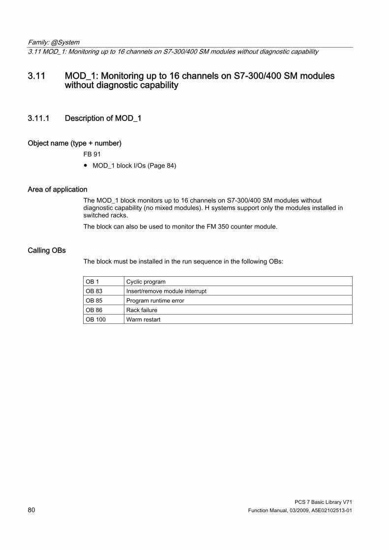
Family: @System 3.11 MOD_1: Monitoring up to 16 channels on S7-300/400 SM modules without diagnostic capability
PCS 7 Basic Library V71 80 Function Manual, 03/2009, A5E02102513-01
3.11 MOD_1: Monitoring up to 16 channels on S7-300/400 SM modules without diagnostic capability
3.11.1 Description of MOD_1
Object name (type + number) FB 91 ● MOD_1 block I/Os (Page 84)
Area of application The MOD_1 block monitors up to 16 channels on S7-300/400 SM modules without diagnostic capability (no mixed modules). H systems support only the modules installed in switched racks. The block can also be used to monitor the FM 350 counter module.
Calling OBs The block must be installed in the run sequence in the following OBs: OB 1 Cyclic program OB 83 Insert/remove module interrupt OB 85 Program runtime error OB 86 Rack failure OB 100 Warm restart

Family: @System 3.11 MOD_1: Monitoring up to 16 channels on S7-300/400 SM modules without diagnostic capability
PCS 7 Basic Library V71 Function Manual, 03/2009, A5E02102513-01 81
Use in CFC The following actions are executed automatically with the "Generate module drivers" CFC function: ● The MOD_1 block is installed in its runtime group downstream of the RACK block runtime
group in the above-mentioned OBs. ● The MODE_xx inputs (mode of module channels xx) are configured. ● The logical base address of the LADDR module is configured. ● The OUT structures CPU_DIAG of the OB_BEGIN block and RAC_DIAG of the RACK
block are interconnected with the IN_OUT structures of the same name of MOD_1. ● The EN input is interconnected with the output of an AND block.
Its inputs are interconnected with the outputs EN_SUBx (x = number of the DP master system) of the OB_BEGIN block, EN_Rxxx (xxx = rack/station number) of the SUBNET block and EN_Mxx (xx = module number) of the RACK block.
● The output parameter of DXCHG_xx is interconnected with the following channel block at the DataXchg parameter.
● The output parameter of O_MS is interconnected with the following channel block at the MS parameter.
Function The MOD_1 block analyzes all events that affect a module and its channels acyclically. It generates a channel-specific MODE (Page 313) and value status for the signal processing blocks. ALARM_8P reports the events. The block is enabled by the higher-level RACK block at runtime. The event to be evaluated can be found in the CPU_DIAG start information of the OB_DIAG block. There is a MODE_xx input for each signal channel of the module. The module channel configuration data created in HW Config is reported here. The function writes MODE_xx to the low word of the OMODE_xx (Page 312) output parameter. This occurs only during startup or if you set ACC_MODE = TRUE. The current channel value status is written to the most significant byte. If the result is positive, the system sets OMODE_xx = 16#80xxxxxx. The following events lead to the value status "invalid value due to higher-level error" (OMODE_xx = 16#40xxxxxx): ● Events that are evaluated by the RACK block:
– Rack failure (OB 86) (output parameter QRACKF = TRUE) ● Events evaluated by the MOD block:
– Program execution error (OB 85) (output parameter QPERAF = TRUE) – Module removed (OB 83) (output parameter QMODF = TRUE)
"Module removed" and "I/O access error" events are reported to the OS by ALARM_8P. The diagnostic interrupt function distinguishes between module and channel errors, and each channel is assigned a message ID. The system verifies during startup that the module is available (plugged in). The module status information read here is made available in the form of service output parameters (MOD_INF). You will find further information about faults in the System Software for S7-300/400 System and Standard Functions reference manual.

Family: @System 3.11 MOD_1: Monitoring up to 16 channels on S7-300/400 SM modules without diagnostic capability
PCS 7 Basic Library V71 82 Function Manual, 03/2009, A5E02102513-01
Redundancy The higher-level RACK block monitors the redundancy of DP master systems operating in an H system.
MODE setting For further information, refer to the section "MODE (Page 313) settings".
Note If you make changes to the MODE_xx input configurations at runtime, they are not accepted at the outputs until you set the ACC_MODE input to 1.
OMODE Structure You will find further information in the "OMODE (Page 312)" section.
Valid channel display The available channels on a module are displayed in the CH_EXIST output by setting a bit in the DWORD, starting at bit 0, for every existing channel. If the bit assigned to a channel = 0, the channel is not available. Output CH_OK displays the valid channels on a module by setting a bit to TRUE for every valid channel, where bit 0 is assigned to channel 0, etc. If the bit assigned to a channel is 0, the channel is faulty. If a module error occurs, all channels are disrupted.
Addressing You will find further information in the "Addressing (Page 323)" section.
Error handling The plausibility of the input parameters is not checked. You will find further information about error handling in the "Error information for output parameter MSG_STAT (Page 322)" section.
Service Information To analyze faults, the module status information entered during startup is read via the structured MOD_INF output parameter. You will find further information in the System Software for S7-300/400 System and Standard Functions; System Status List, Module Status Information reference manual.
Startup characteristics After a restart/initial startup, the system verifies that the module is available under its logical base address. A restart (OB 100) is reported via the LSB in byte 2 of the OMODE_xx (Page 312) ouptuts.
Family: @System 3.11 MOD_1: Monitoring up to 16 channels on S7-300/400 SM modules without diagnostic capability
PCS 7 Basic Library V71 Function Manual, 03/2009, A5E02102513-01 83
Time response Not available
Message functionality MOD_1 uses ALARM_8P to report module errors. The DELAY1 and DELAY2 inputs are used to delay the reporting of I/O access error messages. DELAY1 allows you to enter a time in seconds for which the block will wait for a higher-priority error (rack failure or removal/insertion) following a program execution error (OB 85) before it outputs the message. The message is output only under the condition that no higher-priority error is reported within this delay time. DELAY2 determines the number of seconds the block waits after the higher-priority error has been reported outgoing until it outputs the queued I/O access error as well. The default of both values is 2 seconds. The message function can be disabled by setting EN_MSG = FALSE.
Operator control and monitoring Note: If you selected the "Enable operator control and monitoring" option in the block object properties in the CFC, the variables transferred to the OS are identified under "I/Os of ..." (OCM column, "+"). Default: Option not activated. If asset management is used in the project, and the diagnostic pictures have been generated, then the faceplate can be called via its block icon. ● Asset management block icons (Page 284) ● Asset management faceplates (Page 286)
Additional information For further information, refer to the sections: Message texts and associated values of MOD_1 (Page 86) Maintenance status of MS (Page 326) You will find more information on this in PCS 7 Advanced Process Library > Basics of APL > General functions of the blocks > Operating, monitoring and reporting > Maintenance release

Family: @System 3.11 MOD_1: Monitoring up to 16 channels on S7-300/400 SM modules without diagnostic capability
PCS 7 Basic Library V71 84 Function Manual, 03/2009, A5E02102513-01
3.11.2 I/Os of MOD_1/MOD_2 The MOD_1 and MOD_2 block I/Os are identical with the exception of the number of MODE_xx and OMODE_xx. The number of monitored channels determines the corresponding number of I/O parameters (xx). The factory setting of the block display in the CFC is identified in the "I/O" column: I/O name bold = I/O visible, I/O name normal = I/O not visible. You will find explanations of and information about the abbreviations used in "General information about the block description (Page 9)". I/O (parameters)
Meaning Data type Preset Type O&M
ACC_MODE 1 = accept MODE settings BOOL 0 IO CH_EXIST Channel exists DWORD 0 O + CH_OK Channel OK DWORD 0 O + CPU_DIAG System structure: CPU diagnostics STRUCT IO DELAY1 Alarm delay 1 (s) INT 2 I DELAY2 Alarm delay 2 (s) INT 2 I DXCHG_xx Bidirectional data exchange channel (xx = 00 - 31)
Bit 0= Release for maintenance Bit 1-31 = Reserve
DWORD 0 O
EN_MSG 1 = enable message BOOL 1 I EV_ID Message number DWORD 0 I EXT_STAT Release for maintenance - extended status DWORD 0 O + LADDR Logic address of the module INT 0 I MOD_INF System structure: Module parameter STRUCT O MODE_xx Channel mode (xx = 00 - 15/00 - 31) WORD 0 I MS Maintenance status DWORD 0 I + MSG_ACK Message acknowledgement WORD 0 O MSG_STAT Message error information WORD 0 O O_MS Maintenance status DWORD 0 O OMODE_xx Channel mode (xx = 00 - 15/00 - 31) DWORD 0 O QERR 1 = program error BOOL 1 O QMODF 1 = module removed/defective BOOL 0 O QPERAF 1 = I/O access error BOOL 0 O QRACKF 1 = rack/station error BOOL 0 O RAC_DIAG System structure: Rack diagnostics STRUCT IO RACK_NO Rack number BYTE 0 I SLOT_NO Slot number BYTE 0 I SUBN_TYP 1 = external DP interface BOOL 0 I SUBN1_ID ID of the primary DP master system BYTE 255 I SUBN2_ID ID of the redundant DP master system BYTE 255 I

Family: @System 3.11 MOD_1: Monitoring up to 16 channels on S7-300/400 SM modules without diagnostic capability
PCS 7 Basic Library V71 Function Manual, 03/2009, A5E02102513-01 85
Additional information For further information, refer to the sections: Message texts and associated values of MOD_1/MOD_2 (Page 86) Maintenance status of MS (Page 326)
See also OMODE Settings for SM Modules (Page 312)
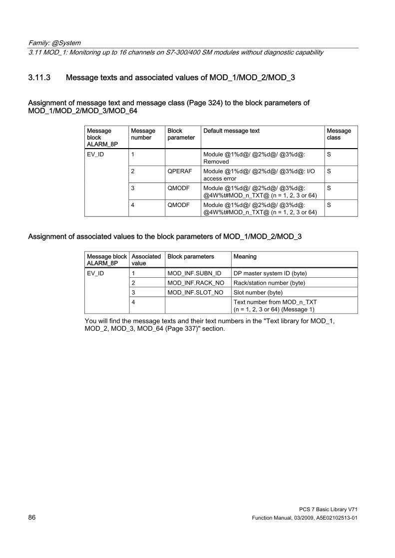
Family: @System 3.11 MOD_1: Monitoring up to 16 channels on S7-300/400 SM modules without diagnostic capability
PCS 7 Basic Library V71 86 Function Manual, 03/2009, A5E02102513-01
3.11.3 Message texts and associated values of MOD_1/MOD_2/MOD_3
Assignment of message text and message class (Page 324) to the block parameters of MOD_1/MOD_2/MOD_3/MOD_64
Message block ALARM_8P
Message number
Block parameter
Default message text Message class
1 Module @1%d@/ @2%d@/ @3%d@: Removed
S
2 QPERAF Module @1%d@/ @2%d@/ @3%d@: I/O access error
S
3 QMODF Module @1%d@/ @2%d@/ @3%d@: @4W%t#MOD_n_TXT@ (n = 1, 2, 3 or 64)
S
EV_ID
4 QMODF Module @1%d@/ @2%d@/ @3%d@: @4W%t#MOD_n_TXT@ (n = 1, 2, 3 or 64)
S
Assignment of associated values to the block parameters of MOD_1/MOD_2/MOD_3 Message block ALARM_8P
Associated value
Block parameters Meaning
1 MOD_INF.SUBN_ID DP master system ID (byte) 2 MOD_INF.RACK_NO Rack/station number (byte) 3 MOD_INF.SLOT_NO Slot number (byte)
EV_ID
4 Text number from MOD_n_TXT (n = 1, 2, 3 or 64) (Message 1)
You will find the message texts and their text numbers in the "Text library for MOD_1, MOD_2, MOD_3, MOD_64 (Page 337)" section.

Family: @System 3.12 MOD_2: Monitoring 32 channels on S7-300/400 SM modules without diagnostic capability
PCS 7 Basic Library V71 Function Manual, 03/2009, A5E02102513-01 87
3.12 MOD_2: Monitoring 32 channels on S7-300/400 SM modules without diagnostic capability
3.12.1 Description of MOD_2
Object name (type + number) FB 92 ● MOD_2 block I/Os (Page 91)
Area of application The MOD_2 block monitors 32 channels on S7-300/400 SM modules without diagnostic capability (no mixed modules). H systems support only the modules installed in switched racks.
Calling OBs The block must be installed in the run sequence in the following OBs: OB 1 Cyclic program OB 83 Insert/remove module interrupt OB 85 Program runtime error OB 86 Rack failure OB 100 Warm restart

Family: @System 3.12 MOD_2: Monitoring 32 channels on S7-300/400 SM modules without diagnostic capability
PCS 7 Basic Library V71 88 Function Manual, 03/2009, A5E02102513-01
Use in CFC The following actions are executed automatically with the "Generate module drivers" CFC function: ● The MOD_2 block is installed in its runtime group downstream of the RACK block runtime
group in the above-mentioned OBs. ● The MODE_xx inputs (mode of module channels xx) are configured. ● The logical base address of the LADDR module is configured. ● The OUT structures CPU_DIAG of the OB_BEGIN block and RAC_DIAG of the RACK
block are interconnected with the IN_OUT structures of the same name of MOD_2. ● The EN input is interconnected with the output of an AND block.
Its inputs are interconnected with the outputs EN_SUBx (x = number of the DP master system) of the OB_BEGIN block, EN_Rxxx (xxx = rack/station number) of the SUBNET block and EN_Mxx (xx = module number) of the RACK block.
● The output parameter of DXCHG_xx is interconnected with the following channel block at the DataXchg parameter.
● The output parameter of O_MS is interconnected with the following channel block at the MS parameter.
Function Block MOD_2 analyzes all events affecting a module and its channels in non-cyclic mode. It generates a channel-specific MODE (Page 313) and value status for the signal processing blocks. ALARM_8P reports the events. The block is enabled to run by the higher-level RACK block. The event to be evaluated can be found in the CPU_DIAG start information of the OB_DIAG block. There is a MODE_xx input for each signal channel of the module. The module channel configuration data created in HW Config is reported here. The function writes MODE_xx to the low word of the OMODE_xx (Page 312) output parameter. This occurs only during startup or if you set ACC_MODE = TRUE. The current channel value status is written to the most significant byte. If the result is positive, the system sets OMODE_xx = 16#80xxxxxx. The following events lead to the value status "invalid value due to higher-level error" (OMODE_xx = 16#40xxxxxx): ● Events that are evaluated by the RACK block:
– Rack failure (OB 86) (output parameter QRACKF = TRUE) ● Events evaluated by the MOD block:
– Program execution error (OB 85) (output parameter QPERAF = TRUE) – Module removed (OB 83) (output parameter QMODF = TRUE)
"Module removed" and "I/O access error" events are reported to the OS by ALARM_8P. The diagnostic interrupt function distinguishes between module and channel errors, and each channel is assigned a message ID. The system verifies during startup that the module is available (plugged in). The module status information read here provides this data in the form of service output parameters (MOD_INF). You will find further information about errors in the System Software for S7-300/40; System and Standard Functions reference manual.
Family: @System 3.12 MOD_2: Monitoring 32 channels on S7-300/400 SM modules without diagnostic capability
PCS 7 Basic Library V71 Function Manual, 03/2009, A5E02102513-01 89
Redundancy The higher-level RACK block monitors the redundancy of DP master systems operating in an H system.
MODE setting You will find more information about this in the "OMODE settings (Page 313)" section.
Note If you change the parameter settings for the MODE_xx inputs at runtime, these changes will not be accepted at the outputs until the ACC_MODE is set to 1.
OMODE Structure You will find further information in the "OMODE (Page 312)" section.
Valid channel display The available channels on a module are displayed in the CH_EXIST output by setting a bit in the DWORD, starting at bit 0, for every existing channel. If the bit assigned to a channel = 0, the channel is not available. Output CH_OK displays the valid channels on a module by setting a bit to TRUE for every valid channel, where bit 0 is assigned to channel 0, etc. If the bit assigned to a channel is 0, the channel is faulty. If a module error occurs, all channels are disrupted.
Addressing You will find further information about this in the "Addressing (Page 323)" section.
Error handling The plausibility of the input parameters is not checked. You will find further information about error handling in the "Error information for output parameter MSG_STAT (Page 322)" section.
Service Information To analyze faults, the module status information entered during startup is read via the MOD_INF structured output parameter. You will find more information about this in the System Software for S7-300/400 System and Standard Functions; System Status List, Module Status Information reference manual.
Startup characteristics After a restart/initial startup, the system verifies that the module is available under its logical base address. A restart (OB 100) is reported via the LSB in byte 2 of the OMODE_xx (Page 312) outputs.

Family: @System 3.12 MOD_2: Monitoring 32 channels on S7-300/400 SM modules without diagnostic capability
PCS 7 Basic Library V71 90 Function Manual, 03/2009, A5E02102513-01
Time response Not available
Message functionality MOD_2 uses ALARM_8P to report module errors. The DELAY1 and DELAY2 inputs are used to delay the reporting of I/O access error messages. DELAY1 allows you to enter a time in seconds for which the block will wait for a higher-priority error (rack failure or removal/insertion) following a program execution error (OB 85) before it outputs the message. The message is output only under the condition that no higher-priority error is reported within this delay time. DELAY2 determines the number of seconds the block waits after the higher-priority error has been reported outgoing until it outputs the queued I/O access error as well. Both values are set to 2 seconds by default. The message function can be disabled by setting EN_MSG = FALSE.
Operator control and monitoring Note: If you selected the "Enable operator control and monitoring" option in the block object properties in the CFC, the variables transferred to the OS are identified under "I/Os of ..." (OCM column, "+"). Default: Option not activated. If asset management is used in the project, and the diagnostic screens were generated, the faceplate can be called via its block icon. ● Asset management block icons (Page 284) ● Asset management faceplates (Page 286)
Additional information For further information, refer to the sections: Message texts and associated values of MOD_2 (Page 93) Maintenance status of MS (Page 326) You will find more information on this in PCS 7 Advanced Process Library > Basics of APL > General functions of the blocks > Operating, monitoring and reporting > Maintenance release

Family: @System 3.12 MOD_2: Monitoring 32 channels on S7-300/400 SM modules without diagnostic capability
PCS 7 Basic Library V71 Function Manual, 03/2009, A5E02102513-01 91
3.12.2 I/Os of MOD_1/MOD_2 The MOD_1 and MOD_2 block I/Os are identical with the exception of the number of MODE_xx and OMODE_xx. The number of monitored channels determines the corresponding number of I/O parameters (xx). The factory setting of the block display in the CFC is identified in the "I/O" column: I/O name bold = I/O visible, I/O name normal = I/O not visible. You will find explanations of and information about the abbreviations used in "General information about the block description (Page 9)". I/O (parameters)
Meaning Data type Preset Type O&M
ACC_MODE 1 = accept MODE settings BOOL 0 IO CH_EXIST Channel exists DWORD 0 O + CH_OK Channel OK DWORD 0 O + CPU_DIAG System structure: CPU diagnostics STRUCT IO DELAY1 Alarm delay 1 (s) INT 2 I DELAY2 Alarm delay 2 (s) INT 2 I DXCHG_xx Bidirectional data exchange channel
(xx = 00 - 31) Bit 0= Release for maintenance Bit 1-31 = Reserve
DWORD 0 O
EN_MSG 1 = enable message BOOL 1 I EV_ID Message number DWORD 0 I EXT_STAT Release for maintenance - extended status DWORD 0 O + LADDR Logic address of the module INT 0 I MOD_INF System structure: Module parameter STRUCT O MODE_xx Channel mode (xx = 00 - 15/00 - 31) WORD 0 I MS Maintenance status DWORD 0 I + MSG_ACK Message acknowledgement WORD 0 O MSG_STAT Message error information WORD 0 O O_MS Maintenance status DWORD 0 O OMODE_xx Channel mode (xx = 00 - 15/00 - 31) DWORD 0 O QERR 1 = program error BOOL 1 O QMODF 1 = module removed/defective BOOL 0 O QPERAF 1 = I/O access error BOOL 0 O QRACKF 1 = rack/station error BOOL 0 O RAC_DIAG System structure: Rack diagnostics STRUCT IO RACK_NO Rack number BYTE 0 I SLOT_NO Slot number BYTE 0 I SUBN_TYP 1 = external DP interface BOOL 0 I SUBN1_ID ID of the primary DP master system BYTE 255 I SUBN2_ID ID of the redundant DP master system BYTE 255 I
Family: @System 3.12 MOD_2: Monitoring 32 channels on S7-300/400 SM modules without diagnostic capability
PCS 7 Basic Library V71 92 Function Manual, 03/2009, A5E02102513-01
Additional information For further information, refer to the sections: Message texts and associated values of MOD_1/MOD_2 (Page 93) Maintenance status of MS (Page 326)

Family: @System 3.12 MOD_2: Monitoring 32 channels on S7-300/400 SM modules without diagnostic capability
PCS 7 Basic Library V71 Function Manual, 03/2009, A5E02102513-01 93
3.12.3 Message texts and associated values of MOD_1/MOD_2/MOD_3
Assignment of message text and message class (Page 324) to the block parameters of MOD_1/MOD_2/MOD_3/MOD_64
Message block ALARM_8P
Message number
Block parameter
Default message text Message class
1 Module @1%d@/ @2%d@/ @3%d@: Removed
S
2 QPERAF Module @1%d@/ @2%d@/ @3%d@: I/O access error
S
3 QMODF Module @1%d@/ @2%d@/ @3%d@: @4W%t#MOD_n_TXT@ (n = 1, 2, 3 or 64)
S
EV_ID
4 QMODF Module @1%d@/ @2%d@/ @3%d@: @4W%t#MOD_n_TXT@ (n = 1, 2, 3 or 64)
S
Assignment of associated values to the block parameters of MOD_1/MOD_2/MOD_3 Message block ALARM_8P
Associated value
Block parameters Meaning
1 MOD_INF.SUBN_ID DP master system ID (byte) 2 MOD_INF.RACK_NO Rack/station number (byte) 3 MOD_INF.SLOT_NO Slot number (byte)
EV_ID
4 Text number from MOD_n_TXT (n = 1, 2, 3 or 64) (Message 1)
You will find the message texts and their text numbers in the "Text library for MOD_1, MOD_2, MOD_3, MOD_64 (Page 337)" section.
Family: @System 3.13 MOD_3: Monitoring up to 16 channels on S7-200/300/400 SM modules without diagnostic capability
PCS 7 Basic Library V71 94 Function Manual, 03/2009, A5E02102513-01
3.13 MOD_3: Monitoring up to 16 channels on S7-200/300/400 SM modules without diagnostic capability
3.13.1 Description of MOD_3
Object name (type + number) FB 95 ● MOD_3 block I/Os (Page 98)
Area of application The MOD_3 block monitors up to 16 channels on S7-300/400 SM mixed modules without diagnostic capability (I/O modules). H systems support only the modules installed in switched racks.
Calling OBs The block must be installed in the run sequence in the following OBs: OB 1 Cyclic program OB 83 Insert/remove module interrupt OB 85 Program runtime error OB 86 Rack failure OB 100 Warm restart
Use in the CFC The following actions are executed automatically with the "Generate module drivers" CFC function: ● The MOD_3 block is installed in its runtime group downstream of the RACK block runtime
group in the above-mentioned OBs. ● The MODE_xx inputs are configured. ● The logical addresses LADDR and LADDR1 are configured. ● The structures CPU_DIAG of the OB_BEGIN block and RAC_DIAG of the RACK block
are interconnected with the MOD_3 structures of the same name. ● The output parameter of DXCHG_xx is interconnected with the following channel block at
the DataXchg parameter. ● The output parameter of O_MS is interconnected with the following channel block at the
MS parameter.
Family: @System 3.13 MOD_3: Monitoring up to 16 channels on S7-200/300/400 SM modules without diagnostic capability
PCS 7 Basic Library V71 Function Manual, 03/2009, A5E02102513-01 95
Function The MOD_3 block cyclically analyzes all events that affect a module. It generates a channel-specific MODE (Page 313) and value status for the signal processing blocks. ALARM_8P reports the events. The message function can be disabled. The block is enabled to run by the higher-level RACK block. The diagnostic event is entered in the CPU_DIAG start information of the OB_BEGIN block. There is a MODE_xx input for each signal channel of the module. The module channel configuration data created in HW Config is reported here. MODE_00 to MODE_15 inputs are available for encoding up to 16 input channels, and MODE_16 … MODE_31 for encosing up to 16 output channels. The function writes MODE_xx to the low word of the OMODE_xx (Page 312) output parameter. This occurs only during startup or if you set ACC_MODE = TRUE. The current channel value status is written to the most significant byte. If the result is positive, the system sets OMODE_xx = 16#80xxxxxx. The following events lead to the value status "invalid value due to higher-level error" (OMODE_xx = 16#40xxxxxx): ● Events that are evaluated by the RACK block:
– Rack failure (OB 86) (output parameter QRACKF = TRUE) – Program execution error (OB 85) (output parameter QRACKF = TRUE)
● Events that are evaluated by the MOD block: – I/O access error (OB 85) (output parameter QPERAF = TRUE) – Module removed (OB 83) (output parameter QMODF = TRUE)
"Module removed" and "I/O access error" events are reported to the OS by ALARM_8P. The diagnostic interrupt function distinguishes between module and channel errors, and each channel is assigned a message ID. The system verifies during startup that the module is available (plugged in). The module status information read here makes this data available in the form of service output parameters (MOD_INF). You will find further information about faults in the System Software for S7-300/400 System and Standard Functions reference manual.
Redundancy Block MOD_3 supports segment redundancy of H systems operating with distributed I/Os. If you want to use this function, you must configure the SUBN1_ID (connection to CPU 0) and SUBN2_ID (connection to CPU 1) inputs of the SUBNET block with the numbers of the redundant segments. If there is no segment redundancy, the remaining input must be set to the (default) value 16#FF.

Family: @System 3.13 MOD_3: Monitoring up to 16 channels on S7-200/300/400 SM modules without diagnostic capability
PCS 7 Basic Library V71 96 Function Manual, 03/2009, A5E02102513-01
MODE setting You will find more information about this in the "OMODE settings (Page 313)" section.
Note If you change the parameter settings for the MODE_xx inputs at runtime, these changes will not be accepted at the outputs until the ACC_MODE is set to 1.
OMODE Structure You will find further information in the "OMODE (Page 312)" section.
Valid channel display The available channels on a module are displayed in the CH_EXIST output by setting a bit in the DWORD, starting at bit 0, for every existing channel. If the bit assigned to a channel = 0, the channel is not available. Output CH_OK displays the valid channels on a module by setting a bit to TRUE for every valid channel, where bit 0 is assigned to channel 0, etc. If the bit assigned to a channel is 0, the channel is faulty. If a module error occurs, all channels are disrupted.
Addressing You will find further information about this in the "Addressing (Page 323)" section.
Error handling The plausibility of the input parameters is not checked. You will find further information about error handling in the "Error information for output parameter MSG_STAT (Page 322)" section.
Service Information To analyze faults, the module status information entered during startup is read via the MOD_INF structured output parameter. You will find more information about this in the reference manual System Software for S7-300/400 System and Standard Functions; System Status List, Module Status Information.
Startup characteristics After a restart/initial startup, the system verifies that the module is available under its logical base address. A restart (OB 100) is reported via the LSB in byte 2 of the OMODE_xx (Page 312) ouptuts.
Time response Not available
Family: @System 3.13 MOD_3: Monitoring up to 16 channels on S7-200/300/400 SM modules without diagnostic capability
PCS 7 Basic Library V71 Function Manual, 03/2009, A5E02102513-01 97
Message functionality Block MOD_3 uses ALARM_8P to report module errors. The DELAY1 and DELAY2 inputs are used to delay the reporting of I/O access error messages. DELAY1 allows you to enter a time in seconds for which the block will wait for a higher-priority error (rack failure or removal/insertion) following a program execution error (OB 85) before it outputs the message. DELAY2 determines the number of seconds the block waits after the higher-priority error has been reported outgoing until it outputs the queued I/O access error as well. The default value in both cases is 2 seconds. The message function can be disabled by setting EN_MSG = FALSE.
Operator control and monitoring Note: If you selected the "Enable operator control and monitoring" option in the block object properties in the CFC, the variables transferred to the OS are identified under "I/Os of ..." (OCM column, "+"). Default: Option not activated. If asset management is used in the project, and the diagnostic screens were generated, the faceplate can be called via its block icon. ● Asset management block icons (Page 284) ● Asset management faceplates (Page 286)
Additional information For further information, refer to the sections: Message texts and associated values of MOD_3 (Page 100) Maintenance status of MS (Page 326) You will find more information on this in PCS 7 Advanced Process Library > Basics of APL > General functions of the blocks > Operating, monitoring and reporting > Maintenance release
Family: @System 3.13 MOD_3: Monitoring up to 16 channels on S7-200/300/400 SM modules without diagnostic capability
PCS 7 Basic Library V71 98 Function Manual, 03/2009, A5E02102513-01
3.13.2 I/Os of MOD_3 The factory setting of the block display in the CFC is identified in the "I/O" column: I/O name bold = I/O visible, I/O name normal = I/O not visible. You will find explanations of and information about the abbreviations used in "General information about the block description (Page 9)". I/O (parameters)
Meaning Data type Preset Type O&M
ACC_MODE 1 = accept MODE settings BOOL 0 IO CH_EXIST Channel exists DWORD 0 O + CH_OK Channel OK DWORD 0 O + CPU_DIAG System structure: CPU diagnostics STRUCT IO DELAY1 Alarm delay 1 (s) INT 2 I DELAY2 Alarm delay 2 (s) INT 2 I DXCHG_xx Bidirectional data exchange channel
(xx = 00 - 31) Bit 0= Release for maintenance Bit 1-31 = Reserve
DWORD 0 O
EN_MSG 1 = enable message BOOL 1 I EV_ID Message number DWORD 0 I EXT_STAT Release for maintenance - extended status DWORD 0 O + LADDR Logical address of the input channels INT 0 I LADDR1 Logical address of the output channels INT 0 I MOD_INF System structure: Module parameter STRUCT O MODE_xx Channel xx mode WORD 0 I MS Maintenance status DWORD 0 I + MSG_ACK Message acknowledgement WORD 0 O MSG_STAT Message error information WORD 0 O O_MS Maintenance status DWORD 0 O OMODE_xx Channel xx mode DWORD 0 O QERR 1 = program error BOOL 1 O QMODF 1 = module removed/defective BOOL 0 O QPERAF 1 = I/O access error BOOL 0 O QRACKF 1 = failure of the rack BOOL 0 O RAC_DIAG System structure: Rack diagnostics STRUCT IO RACK_NO Rack number BYTE 0 I SLOT_NO Slot number BYTE 0 I SUBN_TYP 1 = external DP interface BOOL 0 I SUBN1_ID ID of the primary DP master system BYTE 255 I SUBN2_ID ID of the redundant DP master system BYTE 255 I

Family: @System 3.13 MOD_3: Monitoring up to 16 channels on S7-200/300/400 SM modules without diagnostic capability
PCS 7 Basic Library V71 Function Manual, 03/2009, A5E02102513-01 99
Additional information For further information, refer to the following sections: Message texts and associated values of MOD_3 (Page 100) Maintenance status of MS (Page 326)

Family: @System 3.13 MOD_3: Monitoring up to 16 channels on S7-200/300/400 SM modules without diagnostic capability
PCS 7 Basic Library V71 100 Function Manual, 03/2009, A5E02102513-01
3.13.3 Message texts and associated values of MOD_1/MOD_2/MOD_3
Assignment of message text and message class (Page 324) to the block parameters of MOD_1/MOD_2/MOD_3/MOD_64
Message block ALARM_8P
Message number
Block parameter
Default message text Message class
1 Module @1%d@/ @2%d@/ @3%d@: Removed
S
2 QPERAF Module @1%d@/ @2%d@/ @3%d@: I/O access error
S
3 QMODF Module @1%d@/ @2%d@/ @3%d@: @4W%t#MOD_n_TXT@ (n = 1, 2, 3 or 64)
S
EV_ID
4 QMODF Module @1%d@/ @2%d@/ @3%d@: @4W%t#MOD_n_TXT@ (n = 1, 2, 3 or 64)
S
Assignment of associated values to the block parameters of MOD_1/MOD_2/MOD_3 Message block ALARM_8P
Associatedvalue
Block parameters Meaning
1 MOD_INF.SUBN_ID DP master system ID (byte) 2 MOD_INF.RACK_NO Rack/station number (byte) 3 MOD_INF.SLOT_NO Slot number (byte)
EV_ID
4 Text number from MOD_n_TXT (n = 1, 2, 3 or 64) (Message 1)
You will find the message texts and their text numbers in the "Text library for MOD_1, MOD_2, MOD_3, MOD_64 (Page 337)" section.

Family: @System 3.14 MOD_4: Monitoring ET 200S modules downstream of a Y-Link
PCS 7 Basic Library V71 Function Manual, 03/2009, A5E02102513-01 101
3.14 MOD_4: Monitoring ET 200S modules downstream of a Y-Link
3.14.1 Description of MOD_4
Object name (type + number) FB 119 ● MOD_4 block I/Os (Page 105)
Area of application Block MOD_4 monitors modules (up to 16 channels) of an ET 200S acting as a DPV0 slave (IM 151 High Feature) downstream of a Y link.
Calling OBs The block must be installed in the run sequence in the following OBs: OB 1 Cyclic program OB 82 Diagnostic interrupt OB 83 Insert/remove module interrupt OB 85 Program runtime error OB 86 Rack failure OB 100 Warm restart
Use in the CFC The following actions are executed automatically with the "Generate module drivers" CFC function: ● Block MOD_4 is installed in its runtime group downstream of the OB_DIAG1 block, which
is used for the ET 200S downstream of a Y link, in the above-mentioned OBs. ● The MODE_xx inputs (mode of module channels xx) are configured. ● The logical base address of the LADDR module is configured. ● The OUT structures CPU_DIAG of the OB_BEGIN block and RAC_DIAG of the
OB_DIAG1 blocks (for DP slave downstream of a Y link, and an OB_DIAG1 for each Y link) are interconnected with the IN_OUT structures RAC_DIAG (DP slave) and RAC_DIAG_L (Y link) of MOD_4.
● The EN input is interconnected with the output of an AND block. whose inputs are interconnected with the outputs EN_SUBx (x = number of the DP master system) of the OB_BEGIN block, EN_Rxxx (xxx = rack/station number) of the SUBNET block, EN_F of the OB_DIAG1 block for the Y link, EN_F of the OB_DIAG1 block for the ET 200S downstream of the Y link, and EN_Mxx (xx = module slot number in the ET 200S) of the DPDIAGV0 block.

Family: @System 3.14 MOD_4: Monitoring ET 200S modules downstream of a Y-Link
PCS 7 Basic Library V71 102 Function Manual, 03/2009, A5E02102513-01
● The DPA_M input is interconnected with the DPA_Mxx (xx= module slot number in the ET 200S) output of the DPDIAGV0 block.
● The output parameter of DXCHG_xx is interconnected with the following channel block at the DataXchg parameter.
● The output parameter of O_MS is interconnected with the following channel block at the MS parameter.
Function Block MOD_4 analyzes all events related to an ET 200S module acyclically. It generates a channel-specific MODE (Page 313) and value status for the signal processing blocks. ALARM_8P reports events separately for each module. The block enabled to run by the higher-level DPDIAGV0 block. The event to be evaluated is available at input DPA_M. Possible byte assignments: 0000000 = Module OK 0000001 = Module error 0000010 = Wrong module 0000011 = Module missing 00001xx = ET 200S failure; x = irrelevant There is a MODE_xx input for each signal channel of the module. The module channel configuration data created in HW Config is reported here. The function writes MODE_xx to the low word of the OMODE_xx (Page 312) output parameter. This only occurs if the module status changes during startup, or if you set ACC_MODE = TRUE. The current channel value status is written to the most significant byte. If the result is positive, the system sets OMODE_xx = 16#80xxxxxx. The following events will lead to the value status "invalid value due to higher-level error" (OMODE_xx = 16#40xxxxxx): ● Events that are evaluated by the OB_DIAG1 block:
– Rack failure (OB 86,OB 83) (output parameter QRACKF = TRUE) ● Events that are evaluated by the MOD block:
– Module diagnostics (OB 82) (output parameter QMODF = TRUE)
ALARM_8P is used to report "Module error ", "Wrong module " or "Module missing " events to the OS.
Redundancy You can not use redundant DP slaves downstream of a Y link.
Family: @System 3.14 MOD_4: Monitoring ET 200S modules downstream of a Y-Link
PCS 7 Basic Library V71 Function Manual, 03/2009, A5E02102513-01 103
MODE setting You will find more information about this in the "OMODE settings (Page 313)" section.
Note If you change the parameter settings for the MODE_xx inputs at runtime, these changes will not be accepted at the outputs until the ACC_MODE is set to 1.
OMODE Structure You will find further information in the "OMODE (Page 312)" section.
Valid channel display The available channels on a module are displayed in the CH_EXIST output by setting a bit in the DWORD, starting at bit 0, for every existing channel. If the bit assigned to a channel = 0, the channel is not available. Output CH_OK displays the valid channels on a module by setting a bit to TRUE for every valid channel, where bit 0 is assigned to channel 0, etc. If the bit assigned to a channel is 0, the channel is faulty. If a module error occurs, all channels are disrupted.
Addressing You will find further information about this in the "Addressing (Page 323)" section.
Error handling The plausibility of input parameters is not checked. You will find further information about error handling in "Error information for output parameter MSG_STAT (Page 322)".
Startup characteristics A restart (OB 100) is reported via the LSB in byte 2 of the OMODE_xx (Page 312) outputs.
Time response Not available
Message functionality MOD_4 uses ALARM_8P to report module errors. The message function can be disabled by setting EN_MSG = FALSE. The block generates the maintenance status MS.

Family: @System 3.14 MOD_4: Monitoring ET 200S modules downstream of a Y-Link
PCS 7 Basic Library V71 104 Function Manual, 03/2009, A5E02102513-01
Operator control and monitoring Note: If you selected the "Enable operator control and monitoring" option in the block object properties in the CFC, the variables transferred to the OS are identified under "I/Os of ..." (OCM column, "+"). Default: Option not activated. If asset management is used in the project, and the diagnostic screens were generated, the faceplate can be called via its block icon. ● Asset management block icons (Page 284) ● Asset management faceplates (Page 286)
Additional information For further information, refer to the sections: Message texts and associated values of MOD_4 (Page 106) Maintenance status of MS (Page 326) You will find more information on this in PCS 7 Advanced Process Library > Basics of APL > General functions of the blocks > Operating, monitoring and reporting > Maintenance release
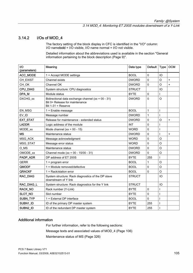
Family: @System 3.14 MOD_4: Monitoring ET 200S modules downstream of a Y-Link
PCS 7 Basic Library V71 Function Manual, 03/2009, A5E02102513-01 105
3.14.2 I/Os of MOD_4 The factory setting of the block display in CFC is identified in the "I/O" column: I/O namebold = I/O visible, I/O name normal = I/O not visible. Detailed information about the abbreviations used is available in the section "General information pertaining to the block description (Page 9)".
I/O (parameters)
Meaning Data type Default Type OCM
ACC_MODE 1 = Accept MODE settings BOOL 0 IO CH_EXIST Channel exists DWORD 0 O + CH_OK Channel OK DWORD 0 O + CPU_DIAG System structure: CPU diagnostics STRUCT IO DPA_M Module status BYTE 0 I DXCHG_xx Bidirectional data exchange channel (xx = 00 - 31)
Bit 0= Release for maintenance Bit 1-31 = Reserve
DWORD 0 O
EN_MSG 1 = Enable message BOOL 1 I EV_ID Message number DWORD 1 I EXT_STAT Release for maintenance - extended status DWORD 0 O + LADDR Logic address of the module INT 0 I MODE_xx Mode channel (xx = 00 - 15) WORD 0 I MS Maintenance status DWORD 0 I + MSG_ACK Message acknowledgment WORD 0 O MSG_STAT Message error status WORD 0 O O_MS Maintenance status DWORD 0 O OMODE_xx Channel mode (xx = 00 - 15/00 - 31) DWORD 0 O PADP_ADR DP address of ET 200S BYTE 255 I QERR 1 = program error BOOL 1 O QMODF 1 = Module removed/defective BOOL 0 O QRACKF 1 = Rack/station error BOOL 0 O RAC_DIAG System structure: Rack diagnostics of the DP slave
downstream of Y link STRUCT IO
RAC_DIAG_L System structure: Rack diagnostics for the Y link STRUCT IO RACK_NO Rack number (Y-Link) BYTE 0 I SLOT_NO Slot number BYTE 0 I SUBN_TYP 1 = External DP interface BOOL 0 I SUBN1_ID ID of the primary DP master system BYTE 255 I SUBN2_ID ID of the redundant DP master system BYTE 255 I
Additional information For further information, refer to the following sections: Message texts and associated values of MOD_4 (Page 106) Maintenance status of MS (Page 326)

Family: @System 3.14 MOD_4: Monitoring ET 200S modules downstream of a Y-Link
PCS 7 Basic Library V71 106 Function Manual, 03/2009, A5E02102513-01
3.14.3 Message Texts and Associated Values of MOD_4
Assignment of message text and message class (Page 324) Message block ALARM_8P
Message number
Default message text Message class
1 Module @1%d@/@2%d@/@3%d@/@4%d@: Error S 2 Module @1%d@/@2%d@/@3%d@/@4%d@: Wrong S
EV_ID
3 Module @1%d@/@2%d@/@3%d@/@4%d@: Missing S
Assignment of associated values Message block ALARM_8P
Associatedvalue
Block parameter
Meaning
1 SUBN_ID DP master system ID (byte) 2 RACK_NO Rack/station number (byte) (Y link) 3 PADP_ADR DP address of ET 200S
EV_ID
4 SLOT_NO Slot number (byte)
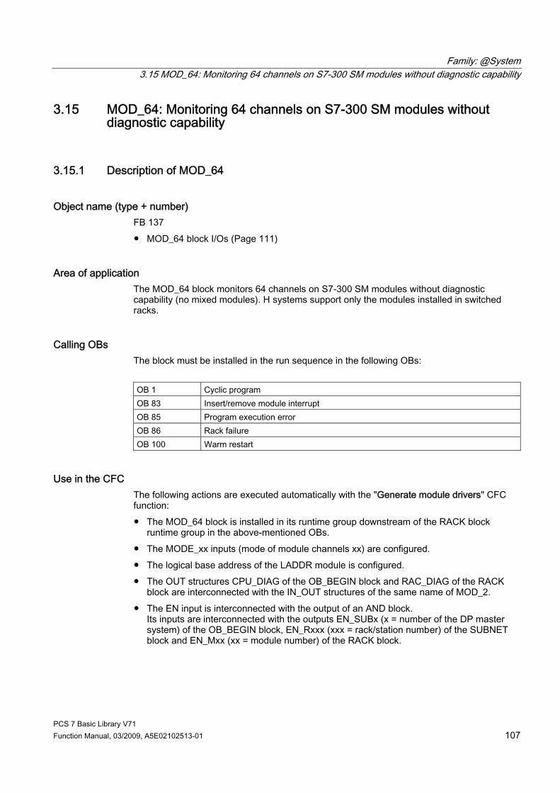
Family: @System 3.15 MOD_64: Monitoring 64 channels on S7-300 SM modules without diagnostic capability
PCS 7 Basic Library V71 Function Manual, 03/2009, A5E02102513-01 107
3.15 MOD_64: Monitoring 64 channels on S7-300 SM modules without diagnostic capability
3.15.1 Description of MOD_64
Object name (type + number) FB 137 ● MOD_64 block I/Os (Page 111)
Area of application The MOD_64 block monitors 64 channels on S7-300 SM modules without diagnostic capability (no mixed modules). H systems support only the modules installed in switched racks.
Calling OBs The block must be installed in the run sequence in the following OBs: OB 1 Cyclic program OB 83 Insert/remove module interrupt OB 85 Program execution error OB 86 Rack failure OB 100 Warm restart
Use in the CFC The following actions are executed automatically with the "Generate module drivers" CFC function: ● The MOD_64 block is installed in its runtime group downstream of the RACK block
runtime group in the above-mentioned OBs. ● The MODE_xx inputs (mode of module channels xx) are configured. ● The logical base address of the LADDR module is configured. ● The OUT structures CPU_DIAG of the OB_BEGIN block and RAC_DIAG of the RACK
block are interconnected with the IN_OUT structures of the same name of MOD_2. ● The EN input is interconnected with the output of an AND block.
Its inputs are interconnected with the outputs EN_SUBx (x = number of the DP master system) of the OB_BEGIN block, EN_Rxxx (xxx = rack/station number) of the SUBNET block and EN_Mxx (xx = module number) of the RACK block.

Family: @System 3.15 MOD_64: Monitoring 64 channels on S7-300 SM modules without diagnostic capability
PCS 7 Basic Library V71 108 Function Manual, 03/2009, A5E02102513-01
● The output parameter of DXCHG_xx is interconnected with the following channel block at the DataXchg parameter.
● The output parameter of O_MS is interconnected with the following channel block at the MS parameter.
Function The MOD_64 block analyzes all events that affect a module and its channels acyclically. It generates a channel-specific MODE (Page 313) and value status for the signal processing blocks. ALARM_8P reports the events. The block is enabled to run by the higher-level RACK block. The event to be evaluated can be found in the CPU_DIAG start information of the OB_DIAG block. There is a MODE_xx input for each signal channel of the module. The module channel configuration data created in HW Config is reported here. The function writes MODE_xx to the low word of the OMODE_xx (Page 312) output parameter. This occurs only during startup or if you set ACC_MODE = TRUE. The current channel value status is written to the most significant byte. If the result is positive, the system sets OMODE_xx = 16#80xxxxxx. The following events will lead to the value status "invalid value due to higher-level error" (OMODE_xx = 16#40xxxxxx): ● Events that are evaluated by the RACK block:
– Rack failure (OB 86) (output parameter QRACKF = TRUE) ● Events that are evaluated by the MOD block:
– Program execution error (OB 85) (output parameter QPERAF = TRUE) – Module removed (OB 83) (output parameter QMODF = TRUE)
"Module removed" and "I/O access error" events are reported to the OS by ALARM_8P. The diagnostics interrupt function distinguishes between module and channel errors, whereby each channel is assigned a message ID. The system verifies during startup that the module is available (plugged in). The module status information that is read here is then available in the form of service output parameters (MOD_INF). You will find further information about errors in the System Software for S7-300/40; System and Standard Functions reference manual.
Redundancy The higher-level RACK block monitors the redundancy of DP master systems operating in an H system.
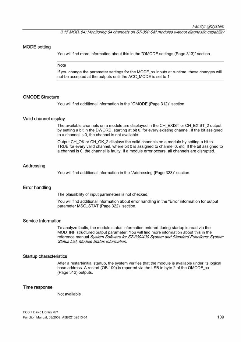
Family: @System 3.15 MOD_64: Monitoring 64 channels on S7-300 SM modules without diagnostic capability
PCS 7 Basic Library V71 Function Manual, 03/2009, A5E02102513-01 109
MODE setting You will find more information about this in the "OMODE settings (Page 313)" section.
Note If you change the parameter settings for the MODE_xx inputs at runtime, these changes will not be accepted at the outputs until the ACC_MODE is set to 1.
OMODE Structure You will find additional information in the "OMODE (Page 312)" section.
Valid channel display The available channels on a module are displayed in the CH_EXIST or CH_EXIST_2 output by setting a bit in the DWORD, starting at bit 0, for every existing channel. If the bit assigned to a channel is 0, the channel is not available. Output CH_OK or CH_OK_2 displays the valid channels on a module by setting a bit to TRUE for every valid channel, where bit 0 is assigned to channel 0, etc. If the bit assigned to a channel is 0, the channel is faulty. If a module error occurs, all channels are disrupted.
Addressing You will find additional information in the "Addressing (Page 323)" section.
Error handling The plausibility of input parameters is not checked. You will find additional information about error handling in the "Error information for output parameter MSG_STAT (Page 322)" section.
Service Information To analyze faults, the module status information entered during startup is read via the MOD_INF structured output parameter. You will find more information about this in the reference manual System Software for S7-300/400 System and Standard Functions; System Status List, Module Status Information.
Startup characteristics After a restart/initial startup, the system verifies that the module is available under its logical base address. A restart (OB 100) is reported via the LSB in byte 2 of the OMODE_xx (Page 312) outputs.
Time response Not available
Family: @System 3.15 MOD_64: Monitoring 64 channels on S7-300 SM modules without diagnostic capability
PCS 7 Basic Library V71 110 Function Manual, 03/2009, A5E02102513-01
Message functionality MOD_64 uses ALARM_8P to report module errors. The DELAY1 and DELAY2 inputs are used to delay the reporting of I/O access error messages. DELAY1 allows you to enter a time in seconds for which the block will wait for a higher-priority error (rack failure or removal/insertion) following a program execution error (OB 85) before it outputs the message. The message is output only under the condition that no higher-priority error is reported within this delay time. DELAY2 determines the number of seconds the block waits after the higher-priority error has been reported outgoing until it outputs the queued I/O access error as well. Both values are set to 2 seconds by default. The message function can be disabled by setting EN_MSG = FALSE.
Operating and monitoring Note: If you selected the "Enable operator control and monitoring" option in the block object properties in the CFC, the variables transferred to the OS are identified under "I/Os of ..." (OCM column, "+"). Default: Option not activated. If asset management is used in the project and the diagnostic screens have been generated, the faceplate can be called via its block icon. ● Asset management block icons (Page 284) ● Asset management faceplates (Page 286)
Additional information For further information, refer to the following sections: Message texts and associated values of MOD_64 (Page 113) Maintenance status of MS (Page 326) You will find more information on this in PCS 7 Advanced Process Library > Basics of APL > General functions of the blocks > Operating, monitoring and reporting > Maintenance release
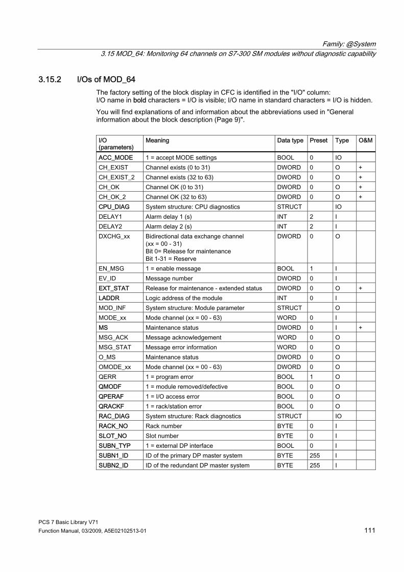
Family: @System 3.15 MOD_64: Monitoring 64 channels on S7-300 SM modules without diagnostic capability
PCS 7 Basic Library V71 Function Manual, 03/2009, A5E02102513-01 111
3.15.2 I/Os of MOD_64 The factory setting of the block display in CFC is identified in the "I/O" column: I/O name in bold characters = I/O is visible; I/O name in standard characters = I/O is hidden. You will find explanations of and information about the abbreviations used in "General information about the block description (Page 9)". I/O (parameters)
Meaning Data type Preset Type O&M
ACC_MODE 1 = accept MODE settings BOOL 0 IO CH_EXIST Channel exists (0 to 31) DWORD 0 O + CH_EXIST_2 Channel exists (32 to 63) DWORD 0 O + CH_OK Channel OK (0 to 31) DWORD 0 O + CH_OK_2 Channel OK (32 to 63) DWORD 0 O + CPU_DIAG System structure: CPU diagnostics STRUCT IO DELAY1 Alarm delay 1 (s) INT 2 I DELAY2 Alarm delay 2 (s) INT 2 I DXCHG_xx Bidirectional data exchange channel
(xx = 00 - 31) Bit 0= Release for maintenance Bit 1-31 = Reserve
DWORD 0 O
EN_MSG 1 = enable message BOOL 1 I EV_ID Message number DWORD 0 I EXT_STAT Release for maintenance - extended status DWORD 0 O + LADDR Logic address of the module INT 0 I MOD_INF System structure: Module parameter STRUCT O MODE_xx Mode channel (xx = 00 - 63) WORD 0 I MS Maintenance status DWORD 0 I + MSG_ACK Message acknowledgement WORD 0 O MSG_STAT Message error information WORD 0 O O_MS Maintenance status DWORD 0 O OMODE_xx Mode channel (xx = 00 - 63) DWORD 0 O QERR 1 = program error BOOL 1 O QMODF 1 = module removed/defective BOOL 0 O QPERAF 1 = I/O access error BOOL 0 O QRACKF 1 = rack/station error BOOL 0 O RAC_DIAG System structure: Rack diagnostics STRUCT IO RACK_NO Rack number BYTE 0 I SLOT_NO Slot number BYTE 0 I SUBN_TYP 1 = external DP interface BOOL 0 I SUBN1_ID ID of the primary DP master system BYTE 255 I SUBN2_ID ID of the redundant DP master system BYTE 255 I
Family: @System 3.15 MOD_64: Monitoring 64 channels on S7-300 SM modules without diagnostic capability
PCS 7 Basic Library V71 112 Function Manual, 03/2009, A5E02102513-01
Additional information For further information, refer to the following sections: Message texts and associated values of MOD_64 (Page 113) Maintenance status of MS (Page 326)
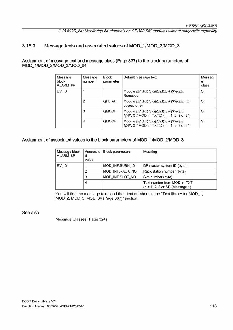
Family: @System 3.15 MOD_64: Monitoring 64 channels on S7-300 SM modules without diagnostic capability
PCS 7 Basic Library V71 Function Manual, 03/2009, A5E02102513-01 113
3.15.3 Message texts and associated values of MOD_1/MOD_2/MOD_3
Assignment of message text and message class (Page 337) to the block parameters of MOD_1/MOD_2/MOD_3/MOD_64
Message block ALARM_8P
Message number
Block parameter
Default message text Message class
1 Module @1%d@/ @2%d@/ @3%d@: Removed
S
2 QPERAF Module @1%d@/ @2%d@/ @3%d@: I/O access error
S
3 QMODF Module @1%d@/ @2%d@/ @3%d@: @4W%t#MOD_n_TXT@ (n = 1, 2, 3 or 64)
S
EV_ID
4 QMODF Module @1%d@/ @2%d@/ @3%d@: @4W%t#MOD_n_TXT@ (n = 1, 2, 3 or 64)
S
Assignment of associated values to the block parameters of MOD_1/MOD_2/MOD_3 Message block ALARM_8P
Associated value
Block parameters Meaning
1 MOD_INF.SUBN_ID DP master system ID (byte) 2 MOD_INF.RACK_NO Rack/station number (byte) 3 MOD_INF.SLOT_NO Slot number (byte)
EV_ID
4 Text number from MOD_n_TXT (n = 1, 2, 3 or 64) (Message 1)
You will find the message texts and their text numbers in the "Text library for MOD_1, MOD_2, MOD_3, MOD_64 (Page 337)" section.
See also Message Classes (Page 324)
Family: @System 3.16 MOD_CP: CP 341/441 diagnostics
PCS 7 Basic Library V71 114 Function Manual, 03/2009, A5E02102513-01
3.16 MOD_CP: CP 341/441 diagnostics
3.16.1 Description of MOD_CP
Object name (type + number) FB 98 ● MOD_CP block I/Os (Page 117)
Area of application Block MOD_CP monitors a CP 341 or CP 441 serial communication module. H systems only support modules in switched racks.
Calling OBs The block must be installed in the run sequence in the following OBs: OB 1 Cyclic program OB 82 Diagnostic interrupt OB 83 Insert/remove module interrupt OB 85 Program runtime error OB 86 Rack failure OB 100 Warm restart
Use in the CFC The following actions are executed automatically with the "Generate module drivers" CFC function: ● The MOD_CP block is installed in its runtime group downstream of the RACK block
runtime group in the above-mentioned OBs. ● The SUBN1_ID, SUBN2_ID, SUBN_TYP, RACK_NO, and SLOT_NO inputs are
configured. ● The logical base address LADDR of the module is configured. ● The OUT structures CPU_DIAG of the OB_BEGIN block and RAC_DIAG of the RACK
block are interconnected with the IN_OUT structures of the same name of MOD_CP. ● The EN input is interconnected with the output of an AND block.
Its inputs are interconnected with the outputs EN_SUBx (x = number of the DP master system) of the OB_BEGIN block, EN_Rxxx (xxx = rack/station number) of the SUBNET block and EN_Mxx (xx = module number) of the RACK block.
Family: @System 3.16 MOD_CP: CP 341/441 diagnostics
PCS 7 Basic Library V71 Function Manual, 03/2009, A5E02102513-01 115
Function and method of operation Block MOD_CP analyzes all events that affect a module and its channels acyclically and generates a value status for the serial communication blocks (such as RCV_341). ALARM_8P is used to report these events. The higher-level RACK block enables the MOD_CP block to run. The event to be evaluated is stored in the CPU_DIAG start and diagnostic information of the OB_BEGIN block. An input (MODE_00) is assigned to the communication channel of the module. Input MODE_01 is reserved for the second CP 441 communication channel, which can be used to report the communication-channel configuration data from HW Config. The driver generator cannot access this data at present, so the SND_341 or RCV_341 block does not evaluate the data either. If user-specific blocks are used, the user can define codes at the MODE (Page 313) input for use in these user-specific blocks. The function writes MODE_xx to the low word of the OMODE_xx (Page 312) output. This occurs only during startup or if you set ACC_MODE = TRUE. The current value status of the communication channel is written to the most significant byte. If the result is positive, the system sets OMODE_xx = 16#80xxxxxx. The following events will lead to the value status "invalid value due to higher-level error" (OMODE_xx = 16#40xxxxxx): ● Events that are evaluated by the RACK block:
– Rack failure (OB 86) (output parameter QRACKF = TRUE) ● Events that are evaluated by the MOD block:
– Program execution error (OB 85) (output parameter QPERAF = TRUE) – Module removed (OB 83) (output parameter QMODF = TRUE) – Diagnostic interrupt (OB 82) Distinguishing between module errors and channel errors
The following events are module errors (QMODF = TRUE output parameter):
ALARM_8P is used to report "Module removed", "I/O access error" and "Diagnostic interrupt" events to WinCC. It is only with the CP441 that the system distinguishes between module and channel errors in response to a diagnostic interrupt; two message IDs (parameter assignment error, line break) are assigned to each channel.
Redundancy The higher-level RACK block monitors the redundancy of DP master systems operating in an H system.
Valid channel display The existing channels on a module are displayed in the CH_EXIST output by setting a bit in the DWORD, starting at bit 0, for every existing channel. If the bit assigned to a channel is 0, the channel is not available. Output CH_OK displays the valid channels on a module by setting a bit to TRUE for every valid channel, where bit 0 is assigned to channel 0, etc. If the bit assigned to a channel is 0, the channel is faulty. If a module error occurs, all channels are disrupted.
Family: @System 3.16 MOD_CP: CP 341/441 diagnostics
PCS 7 Basic Library V71 116 Function Manual, 03/2009, A5E02102513-01
Error handling The plausibility of the input parameters is not checked.
Startup characteristics After a restart/initial startup, the system verifies that the module is available under its logical base address. A restart (OB 100) is reported via the LSB in byte 2 of the OMODE_xx (Page 312) outputs.
Overload behavior The MOD_CP block counts the OB 82 calls. The counter is reset in OB 1. If more than five OB 82 events occur in succession before the cycle control point is reached (OB 1), these events are rejected and the message "OB 82 DP master failure: x Rack: y Slot: z" is output.
Time response Not available
Message functionality MOD_CP uses ALARM_8P to report module errors. The DELAY1 and DELAY2 inputs are used to delay the reporting of I/O access error messages. DELAY1 allows you to enter a time in seconds for which the block will wait for a higher-priority error (rack failure or removal/insertion) following a program execution error (OB 85) before it outputs the message. The message is output only under the condition that no higher-priority error is reported within this delay time. DELAY2 determines the number of seconds the block waits after the higher-priority error has been reported outgoing until it outputs the queued I/O access error as well. Both values are set to 2 seconds by default. The message function can be disabled by setting EN_MSG = FALSE.
Operator control and monitoring Note: If you selected the "Enable operator control and monitoring" option in the block object properties in the CFC, the variables transferred to the OS are identified under "I/Os of ..." (OCM column, "+"). Default: Option not activated. If asset management is used in the project, and the diagnostic screens were generated, the faceplate can be called via its block icon. ● Asset management block icons (Page 284) ● Asset management faceplates (Page 286)
Additional information For further information, refer to the following sections: Message texts and associated values of MOD_CP (Page 118) Maintenance status of MS (Page 326)

Family: @System 3.16 MOD_CP: CP 341/441 diagnostics
PCS 7 Basic Library V71 Function Manual, 03/2009, A5E02102513-01 117
3.16.2 I/Os of MOD_CP The factory setting of the block display in the CFC is identified in the "I/O" column: I/O name bold = I/O visible, I/O name normal = I/O not visible. You will find explanations of and information about the abbreviations used in "General information about the block description (Page 9)". I/O (parameters)
Meaning Data type Preset Type O&M
ACC_MODE 1 = accept MODE settings BOOL 0 IO CH_EXIST Channel exists DWORD 0 O + CH_OK Channel OK DWORD 0 O + CPU_DIAG System structure CPU diagnostics STRUCT IO DELAY1 Alarm delay 1 (s) INT 2 I DELAY2 Alarm delay 2 (s) INT 2 I DIAG_INF System structure Diagnostic information STRUCT O EN_MSG 1 = enable message BOOL 1 I EV_ID Message number DWORD 0 I LADDR Logic address of the module INT 0 I MOD_INF System structure Module parameter STRUCT O MODE_00 Channel 1 mode WORD 0 I MODE_01 Channel 2 mode (CP 441 only) WORD 0 I MS Maintenance status DWORD 0 I + MSG_ACK Message acknowledgement WORD 0 O MSG_STAT Message error information WORD 0 O O_MS Maintenance status DWORD 0 O OMODE_00 Value status/channel 1 mode DWORD 0 O OMODE_01 Value status/channel 2 mode (CP 441 only) DWORD 0 O QERR 1 = program error BOOL 1 O QMODF 1 = module removed/defective BOOL 0 O QPERAF 1 = I/O access error BOOL 0 O QRACKF 1 = rack error BOOL 0 O RAC_DIAG System structure Rack diagnostics STRUCT IO RACK_NO Rack number BYTE 0 I SLOT_NO Slot number BYTE 0 I SUBN_TYP 1 = external DP interface BOOL 0 I SUBN1_ID ID of the primary DP master system BYTE 255 I SUBN2_ID ID of the redundant DP master system BYTE 255 I
Additional information For further information, refer to the following sections: Message texts and associated values of MOD_CP (Page 118) Maintenance status of MS (Page 326)

Family: @System 3.16 MOD_CP: CP 341/441 diagnostics
PCS 7 Basic Library V71 118 Function Manual, 03/2009, A5E02102513-01
3.16.3 Message Texts and Associated Values of MOD_CP
Assignment of message text and message class (Page 324) Message block ALARM_8P
Message number
Block parameter
Default message text Message class
1 QMODF CP @1%d@/@2%d@/@3%d@: Removed S 2 CP @1%d@/@2%d@/@3%d@: I/O access
error S
3 CP @1%d@/@2%d@/@3%d@: @4W%t#MOD_CP_TXT@
S
4 CP @1%d@/@2%d@/@3%d@: Wrong parameter
S
5 CP @1%d@/@2%d@/@3%d@: Wire break
S
6 CP @1%d@/@2%d@/@3%d@/2: Wrong parameter
S
7 CP @1%d@/@2%d@/@3%d@/2: Wire break
S
EV_ID
8
QPERAF
CP @1%d@/@2%d@/@3%d@: Multiple diagnostic interrupt
S
You will find the message texts and their text numbers in the "Text library for MOD_CP (Page 337)" section.
Assignment of associated values Message block ALARM_8P
Associated value
Block parameters
Meaning
1 SUBN_ID DP master system ID (byte) 2 RACK_NO Rack/station number (byte)
EV_ID
3 SLOT_NO Slot number (byte)
SUBN_ID = SUBN1_ID. If SUBN1_ID = 16#FF, the associated value is substituted with SUBN2_ID.
Family: @System 3.17 MOD_D1: Monitoring up to 16 channels on S7-300/400 SM modules with diagnostic functions
PCS 7 Basic Library V71 Function Manual, 03/2009, A5E02102513-01 119
3.17 MOD_D1: Monitoring up to 16 channels on S7-300/400 SM modules with diagnostic functions
3.17.1 Description of MOD_D1
Object name (type + number) FB 93 ● MOD_D1 block I/Os (Page 125)
Area of application The MOD_D1 block monitors up to 16-channel S7-300/400 SM modules with diagnostic capability (no mixed modules), and the power supplies of an ET 200iSP in a redundant configuration. H systems support only the modules installed in switched racks.
Calling OBs The block must be installed in the run sequence in the following OBs: OB 1 Cyclic program OB 82 Diagnostic interrupt OB 83 Insert/remove module interrupt OB 85 Program execution error OB 86 Rack failure OB 100 Warm restart
Family: @System 3.17 MOD_D1: Monitoring up to 16 channels on S7-300/400 SM modules with diagnostic functions
PCS 7 Basic Library V71 120 Function Manual, 03/2009, A5E02102513-01
Use in the CFC The following actions are executed automatically with the "Generate module drivers" CFC function: ● The MOD_D1 block is installed in its runtime group downstream of the RACK block
runtime group in the above-mentioned OBs. ● The MODE_xx (mode of the channels xx of the module), SUBN1_ID, SUBN2_ID, and
SUBN_TYP inputs are configured. ● The logical base address LADDR of the module is configured. ● The OUT structures CPU_DIAG of the OB_BEGIN block and RAC_DIAG of the RACK
block are interconnected with the IN_OUT structures of the same name of MOD_D1. ● The EN input is interconnected with the output of an AND block.
Its inputs are interconnected with the outputs EN_SUBx (x = number of the DP master system) of the OB_BEGIN block, EN_Rxxx (xxx = rack/station number) of the SUBNET block and EN_Mxx (xx = module number) of the RACK block.
● The output parameter of DXCHG_xx is interconnected with the following channel block at the DataXchg parameter.
● The output parameter of O_MS is interconnected with the following channel block at the MS parameter.
Function and method of operation Block MOD_D1 analyzes all events that affect a module and its channels acyclically. It generates a channel-specific MODE (Page 313) and value status for the signal processing blocks. ALARM_8P is used to report these events. MOD_D1 monitors the redundant power supplies for ET 200iSP and reports the failure of a power supply via the slot number of the interface module. The maintenance status (MS) of the module shows, if the power supply fails "Maintenance: Requirement Moderate" an. Block MOD_D1 is enabled by the higher-level RACK block at runtime. The diagnostic event is stored in the CPU_DIAG start and diagnostic information of the OB_BEGIN block. There is a MODE_xx input for each signal channel of the module. The module channel configuration data created in HW Config is reported here. The function writes MODE_xx to the low word of the OMODE_xx (Page 312) output parameter. This occurs only during startup or if you set ACC_MODE = TRUE. The current channel value status is written to the most significant byte. If the result is positive, the system sets OMODE_xx = 16#80xxxxxx. The following events will lead to the value status "invalid value due to higher-level error" (OMODE_xx = 16#40xxxxxx): ● Events that are evaluated by the RACK block:
– Rack failure (OB 86) (output parameter QPERAF = TRUE) ● Events that are evaluated by the MOD block:
– Program execution error (OB 85) (output parameter QPERAF = TRUE) – Module removed (OB 83) (output parameter QMODF = TRUE) – Diagnostic interrupt (OB 82) Distinguishing between module errors and channel errors
Family: @System 3.17 MOD_D1: Monitoring up to 16 channels on S7-300/400 SM modules with diagnostic functions
PCS 7 Basic Library V71 Function Manual, 03/2009, A5E02102513-01 121
The following events are module errors (QMODF = TRUE output parameter):
● External auxiliary voltage missing ● Front connector missing ● Module not configured ● Wrong parameter in module ● Wrong/missing module ● Communication error at a CPU module ● Timeout (watchdog) ● Loss of internal power at a module ● Rack failure ● CPU failure ● EPROM error ● RAM error ● ADC/DAC error ● Fuse tripped ● Power supply 1: Error ● Power supply 2: Error
The following events are channel errors (value status "invalid value", OMODE_xx = 16#00xxxx):
● Configuration/parameter assignment error ● Common-mode errors (analog I/Os only) ● Short-circuit to P ● Short circuit to M ● Interruption at the output transistor ● Wire break ● Reference channel error (analog inputs only) ● Measuring range underflow (only analog inputs) ● Measuring range overflow (analog inputs only) ● Missing load voltage (only analog and digital outputs) ● Missing sensor power supply (digital outputs only) ● Fuse tripped (only digital outputs) ● Ground fault (digital I/Os only) ● Excess temperature (only digital outputs) ALARM_8P is used to report "Module removed", "I/O access error", and "Diagnostic interrupt" events to WinCC.
Family: @System 3.17 MOD_D1: Monitoring up to 16 channels on S7-300/400 SM modules with diagnostic functions
PCS 7 Basic Library V71 122 Function Manual, 03/2009, A5E02102513-01
The diagnostic interrupt function distinguishes between module and channel errors, and each channel is assigned a message ID. Only one incoming/outgoing event can be reported for each channel. As long as an incoming message is queued at a channel, further messages on new events at this channel will be lost. If the event is defined uniquely in the diagnostic information, the corresponding text will be entered in the message. If there are ambiguous entries, the text of the first set bit in the error byte of the diagnostic information will be displayed. When using modules assigned diagnostic functions and more than one error byte for diagnostic information, only the channel xx error text will be output if the error information is not displayed in the first error byte. The system verifies during startup that the module is available (plugged in). The module status information read here makes this data available in the form of service output parameters (MOD_INF). Detailed information about the errors is entered in the DIAG_INF output parameter of data type STRUCT. You will find more information about this in the reference manual System Software for S7-300/400 System and Standard Functions; Diagnostic Data, Byte 0 to Byte 8, Structure of Channel-Specific Diagnostic Data.
Note If you run a HART module in HART MODE (Page 313) =16#070C, any HART protocol errors/configuration changes will be masked by the MOD_D1 driver block, and will not be signaled as channel errors.
Redundancy The higher-level RACK block monitors the redundancy of DP master systems operating in an H system.
MODE setting You will find more information about this in the "OMODE settings (Page 313)" section.
Note If you change the parameter settings for the MODE_xx inputs at runtime, these changes will not be accepted at the outputs until the ACC_MODE is set to 1.
OMODE Structure You will find further information in the "OMODE (Page 312)" section.

Family: @System 3.17 MOD_D1: Monitoring up to 16 channels on S7-300/400 SM modules with diagnostic functions
PCS 7 Basic Library V71 Function Manual, 03/2009, A5E02102513-01 123
Valid channel display The available channels on a module are displayed in the CH_EXIST output by setting a bit in the DWORD, starting at bit 0, for every existing channel. If the bit assigned to a channel = 0, the channel is not available. Output CH_OK displays the valid channels on a module by setting a bit to TRUE for every valid channel, where bit 0 is assigned to channel 0, etc. If the bit assigned to a channel is 0, the channel is faulty. If a module error occurs, all channels are disrupted.
Addressing You will find more information about this in "Addressing (Page 323)". HART modules with read/write access to the process image are configured in the same way as input modules. The set I/O range must always be identical. Example: SM332 AO 2x0/4..20mA HART 332-5TB00-0AB0: Address input range (HW Config)
Address output range (HW Config)
LADDR (decimal/hex)
544 544 544 / 16#0220
Error handling The plausibility of input parameters is not checked. You will find further information about error handling in the "Error information for output parameter MSG_STAT (Page 322)" section.
Service Information To analyze faults, the module status information entered during startup is read via the MOD_INF structured output parameter. You will find more information about this in the reference manual System Software for S7-300/400 System and Standard Functions; System Status List, Module Status Information. Following a diagnostic interrupt, you will also find detailed module diagnostic information in the MODDIAG0 to MODDIAG8 output parameters. You will find more information in the reference manual System Software for S7-300/400 System and Standard Functions; Diagnostic Data, Byte 0 to Byte 8. The CHDIAG00 to CHDIAG15 output parameters contain detailed channel-status information. You will find more information in the reference manual System Software for S7-300/400 System and Standard Functions; Structure of Channel-Specific Diagnostic Data. The system resets this diagnostic information after a diagnostic interrupt has been reported outgoing (no further channel or module errors are queued).
Startup characteristics After a restart/initial startup, the system verifies that the module is available under its logical base address. A restart (OB100) is reported via the LSB in byte 2 of the OMODE_xx (Page 312) outputs.

Family: @System 3.17 MOD_D1: Monitoring up to 16 channels on S7-300/400 SM modules with diagnostic functions
PCS 7 Basic Library V71 124 Function Manual, 03/2009, A5E02102513-01
Overload behavior The MOD_D1 block counts the OB82 calls. The counter is reset in OB1. If more than two OB82 events occur in succession before the cycle control point is reached (OB1), these events are rejected, and the message "OB82 DP master failure: x Rack: y Slot: z" is output.
Time response Not available
Message functionality MOD_D1 uses ALARM_8P_1 to report module errors. The function also calls ALARM_8P_2 and ALARM_8P_3 which are intended for channel errors. The DELAY1 and DELAY2 inputs are used to delay the reporting of I/O access error messages. DELAY1 allows you to enter a time in seconds for which the block will wait for a higher-priority error (rack failure or removal/insertion) following a program execution error (OB85) before it outputs the message. The message is output only under the condition that no higher-priority error is reported within this delay time. DELAY2 determines the number of seconds the block waits after the higher-priority error has been reported outgoing until it outputs the queued I/O access error as well. Both values are set to 2 seconds by default. The message function can be disabled by setting EN_MSG = FALSE.
Operator control and monitoring Note: If you selected the "Enable operator control and monitoring" option in the block object properties in the CFC, the variables transferred to the OS are identified under "I/Os of ..." (OCM column, "+"). Default: Option not activated. If asset management is used in the project, and the diagnostic screens were generated, the faceplate can be called via its block icon. ● Asset management block icons (Page 284) ● Asset management faceplates (Page 286)
Additional information For further information, refer to the following sections: Message texts and associated values of MOD_D1 (Page 127) Maintenance status of MS (Page 326) You will find more information on this in PCS 7 Advanced Process Library > Basics of APL > General functions of the blocks > Operating, monitoring and reporting > Maintenance release
Family: @System 3.17 MOD_D1: Monitoring up to 16 channels on S7-300/400 SM modules with diagnostic functions
PCS 7 Basic Library V71 Function Manual, 03/2009, A5E02102513-01 125
3.17.2 I/Os of MOD_D1/MOD_D2 The MOD_D1 and MOD_D2 block I/Os are identical, with the exception of the number of MODE_xx and OMODE_xx. The number of monitored channels determines the corresponding number of I/O parameters (xx). The factory setting of the block display in the CFC is identified in the "I/O" column: I/O name bold = I/O visible, I/O name normal = I/O not visible. You will find explanations of and information about the abbreviations used in "General information about the block description (Page 9)". I/O (parameters)
Meaning Data type Preset Type O&M
ACC_MODE 1 = accept MODE settings BOOL 0 IO CH_EXIST Channel exists DWORD 0 O + CH_OK Channel OK DWORD 0 O + CPU_DIAG System structure: CPU diagnostics STRUCT IO DELAY1 Alarm delay 1 (s) INT 2 I DELAY2 Alarm delay 2 (s) INT 2 I DXCHG_xx Bidirectional data exchange channel
(xx = 00 - 31) Bit 0= Release for maintenance Bit 1-31 = Reserve
DWORD 0 O
DIAG_INF System structure: Diagnostic information STRUCT 0 O EN_MSG 1 = enable message BOOL 1 I EV_IDx Message number (x = 1 - 3) DWORD 0 I EXT_STAT Release for maintenance - extended status DWORD 0 O + LADDR Logic address of the module INT 0 I MOD_INF System structure: Module parameter STRUCT O MODE_xx Channel xx mode WORD 0 I MS Maintenance status DWORD 0 I + MSG_ACKx Message acknowledgment (x = 1 - 3) WORD 0 O MSGSTATx Message error information (x = 1 - 3) WORD 0 O O_MS Maintenance status DWORD 0 O OMODE_xx Channel mode (xx = 00 - 15/00 - 31) DWORD 0 O QERR 1 = program error BOOL 1 O QMODF 1 = module removed/defective BOOL 0 O QPERAF 1 = I/O access error BOOL 0 O QRACKF 1 = rack error BOOL 0 O RAC_DIAG System structure: Rack diagnostics STRUCT IO RACK_NO Rack number BYTE 0 I SLOT_NO Slot number BYTE 0 I SUBN_TYP 1 = external DP interface BOOL 0 I SUBN1_ID ID of the primary DP master system BYTE 255 I SUBN2_ID ID of the redundant DP master system BYTE 255 I

Family: @System 3.17 MOD_D1: Monitoring up to 16 channels on S7-300/400 SM modules with diagnostic functions
PCS 7 Basic Library V71 126 Function Manual, 03/2009, A5E02102513-01
Additional information For further information, refer to the following sections: Message texts and associated values of MOD_D1 (Page 127) Message texts and associated values of MOD_D2 (Page 137) Maintenance status of MS (Page 326)
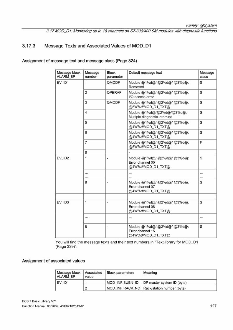
Family: @System 3.17 MOD_D1: Monitoring up to 16 channels on S7-300/400 SM modules with diagnostic functions
PCS 7 Basic Library V71 Function Manual, 03/2009, A5E02102513-01 127
3.17.3 Message Texts and Associated Values of MOD_D1
Assignment of message text and message class (Page 324) Message block ALARM_8P
Message number
Block parameter
Default message text Message class
1 QMODF Module @1%d@/ @2%d@/ @3%d@: Removed
S
2 QPERAF Module @1%d@/ @2%d@/ @3%d@: I/O access error
S
3 Module @1%d@/ @2%d@/ @3%d@: @5W%t#MOD_D1_TXT@
S
4 Module @1%d@/@2%d@/@3%d@: Multiple diagnostic interrupt
S
5 Module @1%d@/ @2%d@/ @3%d@: @4W%t#MOD_D1_TXT@
S
6 Module @1%d@/ @2%d@/ @3%d@: @4W%t#MOD_D1_TXT@
S
7 Module @1%d@/ @2%d@/ @3%d@: @5W%t#MOD_D1_TXT@
F
EV_ID1
8
QMODF
- 1 - Module @1%d@/ @2%d@/ @3%d@:
Error channel 00 @4W%t#MOD_D1_TXT@
S
...
... ...
... ... ...
EV_ID2
8 - Module @1%d@/ @2%d@/ @3%d@: Error channel 07 @4W%t#MOD_D1_TXT@
S
1 - Module @1%d@/ @2%d@/ @3%d@:
Error channel 08 @4W%t#MOD_D1_TXT@
S
...
... ...
... ... ...
EV_ID3
8 - Module @1%d@/ @2%d@/ @3%d@: Error channel 15 @4W%t#MOD_D1_TXT@
S
You will find the message texts and their text numbers in "Text library for MOD_D1 (Page 339)".
Assignment of associated values Message block ALARM_8P
Associatedvalue
Block parameters Meaning
1 MOD_INF.SUBN_ID DP master system ID (byte) EV_ID1 2 MOD_INF.RACK_NO Rack/station number (byte)
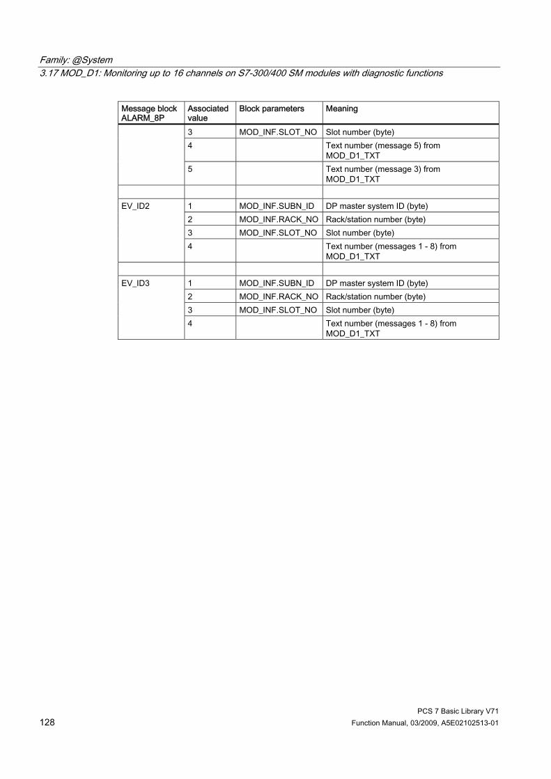
Family: @System 3.17 MOD_D1: Monitoring up to 16 channels on S7-300/400 SM modules with diagnostic functions
PCS 7 Basic Library V71 128 Function Manual, 03/2009, A5E02102513-01
Message block ALARM_8P
Associatedvalue
Block parameters Meaning
3 MOD_INF.SLOT_NO Slot number (byte) 4 Text number (message 5) from
MOD_D1_TXT 5 Text number (message 3) from
MOD_D1_TXT
1 MOD_INF.SUBN_ID DP master system ID (byte) 2 MOD_INF.RACK_NO Rack/station number (byte) 3 MOD_INF.SLOT_NO Slot number (byte)
EV_ID2
4 Text number (messages 1 - 8) from MOD_D1_TXT
1 MOD_INF.SUBN_ID DP master system ID (byte) 2 MOD_INF.RACK_NO Rack/station number (byte) 3 MOD_INF.SLOT_NO Slot number (byte)
EV_ID3
4 Text number (messages 1 - 8) from MOD_D1_TXT

Family: @System 3.18 MOD_D2: Monitoring up to 32 channels of S7-300/400 SM modules with diagnostic functions
PCS 7 Basic Library V71 Function Manual, 03/2009, A5E02102513-01 129
3.18 MOD_D2: Monitoring up to 32 channels of S7-300/400 SM modules with diagnostic functions
3.18.1 Description of MOD_D2
Object name (type + number) FB 94 ● MOD_D2 block I/Os (Page 135)
Area of application Block MOD_D2 monitors up to 32 channels on S7-300/400 SM modules with diagnostic capability (no mixed modules). H systems support only the modules installed in switched racks.
Calling OBs The block must be installed in the run sequence in the following OBs: OB 1 Cyclic program OB 82 Diagnostic interrupt OB 83 Insert/remove module interrupt OB 85 Program runtime error OB 86 Rack failure OB 100 Warm restart

Family: @System 3.18 MOD_D2: Monitoring up to 32 channels of S7-300/400 SM modules with diagnostic functions
PCS 7 Basic Library V71 130 Function Manual, 03/2009, A5E02102513-01
Use in the CFC The following actions are executed automatically with the "Generate module drivers" CFC function: ● The MOD_D2 block is installed in its runtime group downstream of the RACK block
runtime group in the above-mentioned OBs. ● The MODE_xx (mode of the channels xx of the module), SUBN1_ID, SUBN2_ID, and
SUBN_TYP inputs are configured. ● The logical base address LADDR of the module is configured. ● The OUT structures CPU_DIAG of the OB_BEGIN block and RAC_DIAG of the RACK
block are interconnected with the IN_OUT structures of the same name of MOD_D2. ● The EN input is interconnected with the output of an AND block.
Its inputs are interconnected with the outputs EN_SUBx (x = number of the DP master system) of the OB_BEGIN block, EN_Rxxx (xxx = rack/station number) of the SUBNET block and EN_Mxx (xx = module number) of the RACK block.
● The output parameter of DXCHG_xx is interconnected with the following channel block at the DataXchg parameter.
● The output parameter of O_MS is interconnected with the following channel block at the MS parameter.
Function and method of operation Block MOD_D2 analyzes all events that affect a module and its channels acyclically. It generates a channel-specific MODE (Page 313) and value status for the signal processing blocks. ALARM_8P is used to report these events. The message function can be disabled. The block is enabled by the higher-level RACK block at runtime. The diagnostic event is stored in the CPU_DIAG start and diagnostic information of the OB_BEGIN block. There is a MODE_xx input for each signal channel of the module. The module channel configuration data created in HW Config is reported here. The function writes MODE_xx to the low word of the OMODE_xx (Page 312) output parameter. This occurs only during startup or if you set ACC_MODE = TRUE. The current channel value status is written to the most significant byte. If the result is positive, the system sets OMODE_xx = 16#80xxxxxx. The following events will lead to the value status "invalid value due to higher-level error" (OMODE_xx = 16#40xxxxxx): ● Events that are evaluated by the RACK block:
– Rack failure (OB 86) (output parameter QRACKF = TRUE) ● Events that are evaluated by the MOD block:
– Program execution error (OB 85) (output parameter QPERAF = TRUE) – Module removed (OB 83) (output parameter QMODF = TRUE) – Diagnostic interrupt (OB 82) Distinguishing between module errors and channel errors
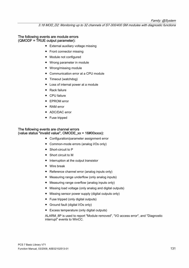
Family: @System 3.18 MOD_D2: Monitoring up to 32 channels of S7-300/400 SM modules with diagnostic functions
PCS 7 Basic Library V71 Function Manual, 03/2009, A5E02102513-01 131
The following events are module errors (QMODF = TRUE output parameter):
● External auxiliary voltage missing ● Front connector missing ● Module not configured ● Wrong parameter in module ● Wrong/missing module ● Communication error at a CPU module ● Timeout (watchdog) ● Loss of internal power at a module ● Rack failure ● CPU failure ● EPROM error ● RAM error ● ADC/DAC error ● Fuse tripped
The following events are channel errors (value status "invalid value", OMODE_xx = 16#00xxxx):
● Configuration/parameter assignment error ● Common-mode errors (analog I/Os only) ● Short-circuit to P ● Short circuit to M ● Interruption at the output transistor ● Wire break ● Reference channel error (analog inputs only) ● Measuring range underflow (only analog inputs) ● Measuring range overflow (analog inputs only) ● Missing load voltage (only analog and digital outputs) ● Missing sensor power supply (digital outputs only) ● Fuse tripped (only digital outputs) ● Ground fault (digital I/Os only) ● Excess temperature (only digital outputs) ALARM_8P is used to report "Module removed", "I/O access error", and "Diagnostic interrupt" events to WinCC.

Family: @System 3.18 MOD_D2: Monitoring up to 32 channels of S7-300/400 SM modules with diagnostic functions
PCS 7 Basic Library V71 132 Function Manual, 03/2009, A5E02102513-01
The diagnostic interrupt function distinguishes between module and channel errors, and each channel is assigned a message ID. Only one incoming or outgoing event can be reported for each channel. As long as an incoming message is queued at a channel, further messages on new events at this channel will be lost. If the event is defined uniquely in the diagnostic information, the corresponding text will be entered in the message. If ambiguous entries exist, the text of the first set bit in the error byte of the diagnostic information will be displayed. When using modules assigned diagnostic functions and more than one error byte for diagnostic information, only the channel xx error text will be output if the error information is not displayed in the first error byte. The system verifies during startup that the module is available (plugged in). The module status information read here makes this data available in the form of service output parameters (MOD_INF). Detailed information about the errors is entered in the DIAG_INF output parameter of data type STRUCT. You will find further information about this in the reference manual System Software for S7-300/400 System and Standard Functions; Diagnostic Data, Byte 0 to Byte 8, Structure of Channel-Specific Diagnostic Data.
Redundancy The block supports segment redundancy of CPU 417H for distributed I/Os. The SUBN1_ID (connection to CPU 0) and SUBN2_ID (connection to CPU 1) inputs are configured with the numbers of the redundant segments. If there is no segment redundancy, the remaining input must be set to the (default) value 16#FF.
MODE setting You will find more information about this in the "OMODE settings (Page 313)" section.
Note If you change the parameter settings for the MODE_xx inputs at runtime, these changes will not be accepted at the outputs until the ACC_MODE is set to 1.
OMODE Structure You will find further information in the "OMODE (Page 312)" section.
Valid channel display The available channels on a module are displayed in the CH_EXIST output by setting a bit in the DWORD, starting at bit 0, for every existing channel. If the bit assigned to a channel = 0, the channel is not available. Output CH_OK displays the valid channels on a module by setting a bit to TRUE for every valid channel, where bit 0 is assigned to channel 0, etc. If the bit assigned to a channel is 0, the channel is faulty. If a module error occurs, all channels are disrupted.
Addressing You will find further information in "Addressing (Page 323)".
Family: @System 3.18 MOD_D2: Monitoring up to 32 channels of S7-300/400 SM modules with diagnostic functions
PCS 7 Basic Library V71 Function Manual, 03/2009, A5E02102513-01 133
Error handling The plausibility of the input parameters is not checked. You will find further information about error handling in "Error information for output parameter MSG_STAT (Page 322)".
Service Information To analyze faults, the module status information entered during startup is read via the MOD_INF structured output parameter. You will find more information about this in the reference manual System Software for S7-300/400 System and Standard Functions; System Status List, Module Status Information. Following a diagnostic interrupt, you will also find detailed module diagnostic information in the MODDIAG0 to MODDIAG10 output parameters. You will find more information in the reference manual System Software for S7-300/400 System and Standard Functions; Diagnostic Data, Byte 0 to Byte 10. The CHDIAG00 to CHDIAG31 output parameters contain detailed channel status information. You will find more information in the reference manual System Software for S7-300/400 System and Standard Functions; Structure of Channel-Specific Diagnostic Data. The system resets this diagnostic information after a diagnostic interrupt has been reported outgoing (no further channel or module errors are queued).
Startup characteristics After a restart/initial startup, the system verifies that the module is available under its logical base address. A restart (OB100) is reported via the LSB in byte 2 of the OMODE_xx (Page 312) outputs.
Time response Not available
Message functionality MOD_D2 uses ALARM_8P_1 to report module errors. In addition, the error blocks ALARM_8P_2, ALARM_8P_3, ALARM_8P_4 and ALARM_8P_5 are called. The DELAY1 and DELAY2 inputs are used to delay the reporting of I/O access error messages. DELAY1 allows you to enter a time in seconds for which the block will wait for a higher-priority error (rack failure or removal/insertion) following a program execution error (OB85) before it outputs the message. The message is output only under the condition that no higher-priority error is reported within this delay time. DELAY2 determines the number of seconds the block waits after the higher-priority error has been reported outgoing until it outputs the queued I/O access error as well. Both values are set to 2 seconds by default. The message function can be disabled by setting EN_MSG = FALSE.

Family: @System 3.18 MOD_D2: Monitoring up to 32 channels of S7-300/400 SM modules with diagnostic functions
PCS 7 Basic Library V71 134 Function Manual, 03/2009, A5E02102513-01
Operator control and monitoring Note: If you selected the "Enable operator control and monitoring" option in the block object properties in the CFC, the variables transferred to the OS are identified under "I/Os of ..." (OCM column, "+"). Default: Option not activated. If asset management is used in the project and the diagnostic screens have been generated, then the faceplate can be called via its icon. ● Asset management block icons (Page 284) ● Asset management faceplates (Page 286)
Additional information For further information, refer to the following sections: Message texts and associated values of MOD_D2 (Page 137) Maintenance status of MS (Page 326) You will find more information on this in PCS 7 Advanced Process Library > Basics of APL > General functions of the blocks > Operating, monitoring and reporting > Maintenance release

Family: @System 3.18 MOD_D2: Monitoring up to 32 channels of S7-300/400 SM modules with diagnostic functions
PCS 7 Basic Library V71 Function Manual, 03/2009, A5E02102513-01 135
3.18.2 I/Os of MOD_D1/MOD_D2 The MOD_D1 and MOD_D2 block I/Os are identical, with the exception of the number of MODE_xx and OMODE_xx. The number of monitored channels determines the corresponding number of I/O parameters (xx). The factory setting of the block display in the CFC is identified in the "I/O" column: I/O name bold = I/O visible, I/O name normal = I/O not visible. You will find explanations of and information about the abbreviations used in "General information about the block description (Page 9)". I/O (parameters)
Meaning Data type Preset Type O&M
ACC_MODE 1 = accept MODE settings BOOL 0 IO CH_EXIST Channel exists DWORD 0 O + CH_OK Channel OK DWORD 0 O + CPU_DIAG System structure: CPU diagnostics STRUCT IO DELAY1 Alarm delay 1 (s) INT 2 I DELAY2 Alarm delay 2 (s) INT 2 I DXCHG_xx Bidirectional data exchange channel
(xx = 00 - 31) Bit 0= Release for maintenance Bit 1-31 = Reserve
DWORD 0 O
DIAG_INF System structure: Diagnostic information STRUCT 0 O EN_MSG 1 = enable message BOOL 1 I EV_IDx Message number (x = 1 - 3) DWORD 0 I EXT_STAT Release for maintenance - extended status DWORD 0 O + LADDR Logic address of the module INT 0 I MOD_INF System structure: Module parameter STRUCT O MODE_xx Channel xx mode WORD 0 I MS Maintenance status DWORD 0 I + MSG_ACKx Message acknowledgment (x = 1 - 3) WORD 0 O MSGSTATx Message error information (x = 1 - 3) WORD 0 O O_MS Maintenance status DWORD 0 O OMODE_xx Channel mode (xx = 00 - 15/00 - 31) DWORD 0 O QERR 1 = program error BOOL 1 O QMODF 1 = module removed/defective BOOL 0 O QPERAF 1 = I/O access error BOOL 0 O QRACKF 1 = rack error BOOL 0 O RAC_DIAG System structure: Rack diagnostics STRUCT IO RACK_NO Rack number BYTE 0 I SLOT_NO Slot number BYTE 0 I SUBN_TYP 1 = external DP interface BOOL 0 I SUBN1_ID ID of the primary DP master system BYTE 255 I SUBN2_ID ID of the redundant DP master system BYTE 255 I

Family: @System 3.18 MOD_D2: Monitoring up to 32 channels of S7-300/400 SM modules with diagnostic functions
PCS 7 Basic Library V71 136 Function Manual, 03/2009, A5E02102513-01
Additional information For further information, refer to the following sections: Message texts and associated values of MOD_D1 (Page 127) Message texts and associated values of MOD_D2 (Page 137) Maintenance status of MS (Page 326)
See also MODE Settings for SM Modules (Page 313) OMODE Settings for SM Modules (Page 312)
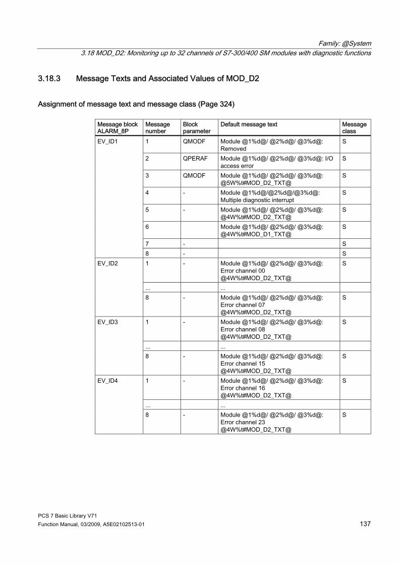
Family: @System 3.18 MOD_D2: Monitoring up to 32 channels of S7-300/400 SM modules with diagnostic functions
PCS 7 Basic Library V71 Function Manual, 03/2009, A5E02102513-01 137
3.18.3 Message Texts and Associated Values of MOD_D2
Assignment of message text and message class (Page 324) Message block ALARM_8P
Message number
Block parameter
Default message text Message class
1 QMODF Module @1%d@/ @2%d@/ @3%d@: Removed
S
2 QPERAF Module @1%d@/ @2%d@/ @3%d@: I/O access error
S
3 QMODF Module @1%d@/ @2%d@/ @3%d@: @5W%t#MOD_D2_TXT@
S
4 - Module @1%d@/@2%d@/@3%d@: Multiple diagnostic interrupt
S
5 - Module @1%d@/ @2%d@/ @3%d@: @4W%t#MOD_D2_TXT@
S
6 Module @1%d@/ @2%d@/ @3%d@: @4W%t#MOD_D1_TXT@
S
7 - S
EV_ID1
8 - S 1 - Module @1%d@/ @2%d@/ @3%d@:
Error channel 00 @4W%t#MOD_D2_TXT@
S
... ...
EV_ID2
8 - Module @1%d@/ @2%d@/ @3%d@: Error channel 07 @4W%t#MOD_D2_TXT@
S
1 - Module @1%d@/ @2%d@/ @3%d@: Error channel 08 @4W%t#MOD_D2_TXT@
S
... ...
EV_ID3
8 - Module @1%d@/ @2%d@/ @3%d@: Error channel 15 @4W%t#MOD_D2_TXT@
S
1 - Module @1%d@/ @2%d@/ @3%d@: Error channel 16 @4W%t#MOD_D2_TXT@
S
... ...
EV_ID4
8 - Module @1%d@/ @2%d@/ @3%d@: Error channel 23 @4W%t#MOD_D2_TXT@
S

Family: @System 3.18 MOD_D2: Monitoring up to 32 channels of S7-300/400 SM modules with diagnostic functions
PCS 7 Basic Library V71 138 Function Manual, 03/2009, A5E02102513-01
Message block ALARM_8P
Message number
Block parameter
Default message text Message class
1 - Module @1%d@/ @2%d@/ @3%d@: Error channel 24 @4W%t#MOD_D2_TXT@
S
... ...
EV_ID5
8 - Module @1%d@/ @2%d@/ @3%d@: Error channel 31 @4W%t#MOD_D2_TXT@
S
You will find the message texts and their text numbers in "Text library for MOD_D2 (Page 337)".
Assignment of associated values Message block ALARM_8P
Associated value
Block parameters Meaning
1 MOD_INF.SUBN_ID DP master system ID (byte) 2 MOD_INF.RACK_NO Rack/station number (byte) 3 MOD_INF.SLOT_NO Slot number (byte)
EV_ID1
4 - Text number (messages 1 - 3) of MOD_D2_TXT
1 MOD_INF.SUBN_ID DP master system ID (byte) 2 MOD_INF.RACK_NO Rack/station number (byte) 3 MOD_INF.SLOT_NO Slot number (byte) 4 - Text number (message 5) of MOD_D2_TXT
EV_ID2
5 - Text number (message 3) of MOD_D2_TXT
1 MOD_INF.SUBN_ID DP master system ID (byte) 2 MOD_INF.RACK_NO Rack/station number (byte) 3 MOD_INF.SLOT_NO Slot number (byte)
EV_ID3
4 - Text number (messages 1 - 8) of MOD_D2_TXT
1 MOD_INF.SUBN_ID DP master system ID (byte) 2 MOD_INF.RACK_NO Rack/station number (byte) 3 MOD_INF.SLOT_NO Slot number (byte)
EV_ID4
4 - Text number (messages 1 - 8) of MOD_D2_TXT
1 MOD_INF.SUBN_ID DP master system ID (byte) 2 MOD_INF.RACK_NO Rack/station number (byte) 3 MOD_INF.SLOT_NO Slot number (byte)
EV_ID5
4 - Text number (messages 1 - 8) of MOD_D2_TXT
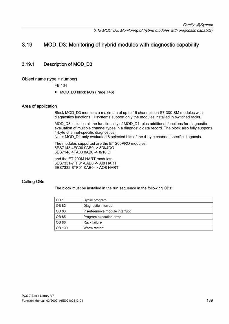
Family: @System 3.19 MOD_D3: Monitoring of hybrid modules with diagnostic capability
PCS 7 Basic Library V71 Function Manual, 03/2009, A5E02102513-01 139
3.19 MOD_D3: Monitoring of hybrid modules with diagnostic capability
3.19.1 Description of MOD_D3
Object name (type + number) FB 134 ● MOD_D3 block I/Os (Page 146)
Area of application Block MOD_D3 monitors a maximum of up to 16 channels on S7-300 SM modules with diagnostics functions. H systems support only the modules installed in switched racks. MOD_D3 includes all the functionality of MOD_D1, plus additional functions for diagnostic evaluation of multiple channel types in a diagnostic data record. The block also fully supports 4-byte channel-specific diagnostics. Note: MOD_D1 only evaluated 8 selected bits of the 4-byte channel-specific diagnosis. The modules supported are the ET 200PRO modules: 6ES7148 4FC00 0AB0 -> 8DI/4DO 6ES7148 4FA00 0AB0 -> 8/16 DI and the ET 200M HART modules: 6ES7331-7TF01-0AB0 -> AI8 HART 6ES7332-8TF01-0AB0 -> AO8 HART
Calling OBs The block must be installed in the run sequence in the following OBs: OB 1 Cyclic program OB 82 Diagnostic interrupt OB 83 Insert/remove module interrupt OB 85 Program execution error OB 86 Rack failure OB 100 Warm restart

Family: @System 3.19 MOD_D3: Monitoring of hybrid modules with diagnostic capability
PCS 7 Basic Library V71 140 Function Manual, 03/2009, A5E02102513-01
Use in the CFC The following actions are executed automatically with the "Generate module drivers" CFC function: ● The MOD_D3 block is installed in its runtime group downstream of the RACK-block
runtime group in the above-mentioned OBs. ● The MODE_xx (mode of the channels xx of the module), SUBN1_ID, SUBN2_ID, and
SUBN_TYP inputs are configured. ● The logical basic address of the LADDR module is configured. ● The OUT structures CPU_DIAG of the OB_BEGIN block and RAC_DIAG of the RACK
block are interconnected with the IN_OUT structures of the same name of MOD_D3. ● The EN input is interconnected with the output of an AND block.
Its inputs are interconnected with the outputs EN_SUBx (x = number of the DP master system) of the OB_BEGIN block, EN_Rxxx (xxx = rack/station number) of the SUBNET block and EN_Mxx (xx = module number) of the RACK block.
● The output parameter of DXCHG_xx is interconnected with the following channel block at the DataXchg parameter.
● The output parameter of O_MS is interconnected with the following channel block at the MS parameter.
Function and operating principle The MOD_D3 block analyzes all events affecting a module and its channels acyclically. It generates a channel-specific MODE (Page 313) and value status (quality code) for the signal processing blocks. ALARM_8P is used to report these events. Execution of the MOD_D3 block is enabled by the higher-level RACK block. The diagnostic event is stored in the CPU_DIAG start and diagnostic information of the OB_BEGIN block. A MODE_xx input exists for each signal channel of the module. This is used for the input of module channel configuration data created in HW Config. The function writes MODE_xx to the low word of the OMODE_xx (Page 312) output parameter. This occurs only during startup or if you set ACC_MODE = TRUE. The current channel value status is written to the most significant byte. If the result is positive, the system sets OMODE_xx = 16#80xxxxxx. The following events will lead to the value status "invalid value due to higher-level error" (OMODE_xx = 16#40xxxxxx): ● Events that are evaluated by the RACK block:
– Rack failure (OB 86) (output parameter QPERAF = TRUE) ● Events that are evaluated by the MOD block:
– Program execution error (OB 85) (output parameter QPERAF = TRUE) – Module removed (OB 83) (output parameter QMODF = TRUE) – Diagnostic interrupt (OB 82) Distinguishing between module errors and channel errors
Family: @System 3.19 MOD_D3: Monitoring of hybrid modules with diagnostic capability
PCS 7 Basic Library V71 Function Manual, 03/2009, A5E02102513-01 141
The following events are module errors (QMODF = TRUE output parameter):
● External auxiliary voltage missing ● Front connector missing ● Module not configured ● Wrong parameter in module ● Wrong/missing module ● Communication error at a CPU module ● Timeout (watchdog) ● Loss of internal power at a module ● Rack failure ● CPU failure ● EPROM error ● RAM error ● ADC/DAC error ● Fuse tripped ● Power supply 1: Error ● Power supply 2: Error
The following events are channel errors (value status "invalid value", OMODE_xx = 16#00xxxx):
● Configuration/parameter assignment error ● Common-mode errors (only analog I/Os) ● Short-circuit to P ● Short circuit to M ● Interruption at the output transistor ● Cable break ● Reference channel error (only analog inputs) ● Measuring range underflow (only analog inputs) ● Measuring range overflow (only analog inputs) ● Missing load voltage (only analog and digital outputs) ● Missing sensor power supply (only digital outputs) ● Fuse tripped (only digital outputs) ● Mass error (only digital I/Os) ● Excess temperature (only digital outputs) ● Undervoltage ● Overvoltage
Family: @System 3.19 MOD_D3: Monitoring of hybrid modules with diagnostic capability
PCS 7 Basic Library V71 142 Function Manual, 03/2009, A5E02102513-01
● Overload ● Hardware interrupt ● Actuator warning ● Safety shutdown ● Ambiguous error ● Error 1 in actuator/sensor ● Error 2 in actuator/sensor ● Channel temporarily not available ALARM_8P is used to report "Module removed", "I/O access error" and "Diagnostics interrupt" events to the OS. The diagnostics interrupt function distinguishes between module and channel errors, whereby each channel is assigned a message ID. Only one incoming/outgoing event can be reported for each channel. As long as an incoming message is queued at a channel, further messages on new events at this channel will be lost. If the event is defined uniquely in the diagnostic information, the corresponding text will be entered in the message. If ambiguous entries exist, the text of the first set bit in the error byte of the diagnostic information will be displayed. When using modules assigned diagnostic functions and more than one error byte for diagnostic information, only the channel xx error text will be output if the error information is not displayed in the first error byte. The system verifies during startup that the module is available (plugged in). The module status information read here provides this data as service output parameters (MOD_INF). Detailed information about the errors is entered in the DIAG_INF output parameter of data type STRUCT. You will find more information about this in the reference manual System Software for S7-300/400 System and Standard Functions; Diagnostic Data, Byte 0 to Byte 8, Structure of Channel-Specific Diagnostic Data.
Note Even if you run a HART module in HART MODE =16#070C, any HART protocol errors/configuration changes that may occur will be masked by the MOD_D3 block, and not signaled as channel errors.
Several channel types can occur in one diagnostic data record. If the "further channel types exist" bit is set, MOD_D3 runs through the entire diagnostic evaluation and handles reporting for each further channel type. HART modules with the firmware update and the new additional channel type 16#66 for measured value calibration are also supported. The new HART channel type 66 can also occur in the diagnostic data record as a further channel type. The new diagnostic data ("channel being calibrated" and "channel temporarily not available") are considered as channel errors and output. The detailed texts are output via the system text library and a corresponding associated value. Channel type 0x66: 1 byte channel diagnostics Bit0 channel being calibrated Bit1 channel temporarily not available
Family: @System 3.19 MOD_D3: Monitoring of hybrid modules with diagnostic capability
PCS 7 Basic Library V71 Function Manual, 03/2009, A5E02102513-01 143
Firmware update The firmware update for the listed HART modules is started by a diagnostic event "OB83 entering state" (remove module) followed directly by diagnostic event "OB83 exiting state" (insert module). With "OB83 exiting state", byte 2 bit 2 is set in data record 0 (1 = STOP mode). Once the firmware is completed, there is a repeated diagnostic event "OB83 entering state" (remove module) followed directly by diagnostic event "OB83 exiting state" (insert module). With "OB83 exiting state", byte 2 bit 2 is reset in data record 0 (0 = RUN mode). In MOD_D3, after an "OB83 exiting state" (module removed) the data record 0 (DS0) is always read extra in OB1 using SFC51 and SZL 00B1 to establish whether bit (1 = STOP mode) is set. If this is the case, this is always recognized as a firmware update and the module continues to be indicated as removed and not available. Only when there is an OB83 (module inserted) with the information in DS0 (0 = RUN mode), is the module indicated as being inserted and available again. It is assumed that "Module change in run" is always set for the ET 200M head modules so that a firmware update of the HART module always calls an OB83. This means that a firmware update cannot trigger an OB86 diagnostic interrupt. The "Generate module driver" function enters 16#0001 in the Feature01 parameter for both HART modules. This means that DS0 is read extra when there is an OB 83 exiting state only when Feature01 = 16#0001 The Feature parameters (FEATURE_01 .. FEATURE_10) are intended for future expansions of the MOD_D3 block and for parameter settings for special module situations. Currently only FEATURE_01 is used as an ID for HART module with a firmware update in RUN.
Redundancy The higher-level RACK block monitors the redundancy of DP master systems operating in an H system.
MODE Setting You will find more information about this in the "OMODE settings (Page 313)" section.
Note If you change the parameter settings for the MODE_xx inputs at runtime, these changes will not be accepted at the outputs until the ACC_MODE is set to 1.
OMODE Structure You will find more information about this in the "OMODE settings (Page 312)" section.

Family: @System 3.19 MOD_D3: Monitoring of hybrid modules with diagnostic capability
PCS 7 Basic Library V71 144 Function Manual, 03/2009, A5E02102513-01
Valid channel display The available channels on a module are displayed in the CH_EXIST output by setting a bit in the DWORD, starting at bit 0, for every existing channel. If the bit assigned to a channel = 0, the channel is not available. Output CH_OK displays the valid channels on a module by setting a bit to TRUE for every valid channel, where bit 0 is assigned to channel 0, etc. If the bit assigned to a channel is 0, the channel is faulty. If a module error occurs, all channels are disrupted.
Addressing You will find more information about this in "Addressing (Page 323)". HART modules with read/write access to the process image are configured in the same way as input modules. The set I/O range must always be identical. Example: SM 332 AO 2x0/4..20mA HART 332-5TB00-0AB0: Address input range (HW Config) Address output range (HW Config) LADDR (decimal/hex) 544 544 544 / 16#0220
Error handling The plausibility of the input parameters is not checked. You will find more information about error handling in "Error information of output parameter MSG_STAT" (Page 322).
Service Information To analyze faults, the module status information entered during startup is read via the MOD_INF structured output parameter. You will find more information about this in the reference manual System Software for S7-300/400 System and Standard Functions; System Status List, Module Status Information. Following a diagnostic interrupt, you will also find detailed module diagnostic information in the MODDIAG0 to MODDIAG8 output parameters. You will find more information in the reference manual System Software for S7-300/400 System and Standard Functions; Diagnostic Data, Byte 0 to Byte 8. The CHDIAG00 to CHDIAG15 output parameters contain detailed channel-status information. You will find more information in the reference manual System Software for S7-300/400 System and Standard Functions; Structure of Channel-Specific Diagnostic Data. The system resets this diagnostic information after a diagnostic interrupt has been reported outgoing (no further channel or module errors are queued).
Startup characteristics After a restart/initial startup, the system verifies that the module is available under its logical base address. A restart (OB100) is reported via the LSB in byte 2 of the OMODE_xx ouptuts.
Family: @System 3.19 MOD_D3: Monitoring of hybrid modules with diagnostic capability
PCS 7 Basic Library V71 Function Manual, 03/2009, A5E02102513-01 145
Overload Behavior The MOD_D3 block counts the OB82 calls. The counter is reset in OB1. If more than two OB82 events occur in succession before the cycle control point is reached (OB1), these events are rejected and the message "OB82 DP master failure: x Rack: y Slot: z" is output.
Time response Not available
Message response MOD_D3 uses ALARM_8P_1 to report module errors. The function also calls ALARM_8P_2 and ALARM_8P_3 which are intended for channel errors. The inputs DELAY1 and DELAY2 are used to delay the output of I/O access error messages. DELAY1 allows you to enter a time in seconds for which the block will wait for a higher-priority error (rack failure or removal/insertion) following a program execution error (OB85) before it outputs the message. The message is output only under the condition that no higher-priority error is reported within this delay time. DELAY2 determines the number of seconds the block waits after the higher-priority error has been reported outgoing until it outputs the queued I/O access error as well. Both values are set to 2 seconds by default. The message function can be disabled by setting EN_MSG = FALSE.
Operating and monitoring Note: If you have selected the "Enable operator control and monitoring" option in the block object properties in the CFC, the variables transferred to the OS are identified under "I/Os of ..." (OCM column, "+"). Default: Option not activated. If asset management is used in the project and the diagnostic pictures have been generated, then the faceplate can be called via its block icon. Asset management block icons (Page 284) Asset management faceplates (Page 286)
Additional information You will find more information in: Message texts and associated values of MOD_D3 (Page 148) Maintenance status of MS (Page 326) You will find more information on this in PCS 7 Advanced Process Library > Basics of APL > General functions of the blocks > Operating, monitoring and reporting > Maintenance release
Family: @System 3.19 MOD_D3: Monitoring of hybrid modules with diagnostic capability
PCS 7 Basic Library V71 146 Function Manual, 03/2009, A5E02102513-01
3.19.2 I/Os of MOD_D3 The factory setting of the block display in CFC is identified in the "I/O" column: I/O name in bold characters = I/O is visible; I/O name in standard characters = I/O is hidden. You will find explanations of and information about the abbreviations used in "General information about the block description (Page 9)".
I/O (parameters)
Meaning Data type Default Type OCM
ACC_MODE 1 = accept MODE settings BOOL 0 IO CH_EXIST Channel exists DWORD 0 O + CH_OK Channel OK DWORD 0 O + CPU_DIAG System structure: CPU diagnostics STRUCT IO DELAY1 Alarm delay 1 (s) INT 2 I DELAY2 Alarm delay 2 (s) INT 2 I DIAG_INF System structure: Diagnostic information STRUCT 0 O DXCHG_xx Bidirectional data exchange channel (xx = 00 - 31)
Bit 0 = Release for maintenance Bits 1-31 = Reserve
DWORD 0 O
EN_MSG 1 = enable message BOOL 1 I EV_IDx Message number (x = 1 - 3) DWORD 0 I EXT_STAT Release for maintenance - extended status DWORD 0 O + FEATURE_xx Feature parameter (xx = 01 - 04) WORD 0 I FEATURE_yy Feature parameter (yy = 05 - 10) DWORD 0 I LADDR Logic input address of the module INT 0 I LADDR1 Logical output address of the module (if output address is
not the same as input address). INT 0 I
MOD_INF System structure: Module parameter STRUCT O MODE_xx Mode channel xx (xx = 00 - 15) WORD 0 I MS Maintenance status DWORD 0 I + MSG_ACKx Message acknowledgment (x = 1 - 3) WORD 0 O MSGSTATx Message error information (x = 1 - 3) WORD 0 O O_MS Maintenance status DWORD 0 O OMODE_xx Mode channel (xx = 00 - 15) DWORD 0 O QERR 1 = program error BOOL 1 O QMODF 1 = module removed/defective BOOL 0 O QPERAF 1 = I/O access error BOOL 0 O QRACKF 1 = rack error BOOL 0 O RAC_DIAG System structure: Rack diagnostics STRUCT IO RACK_NO Rack number BYTE 0 I SLOT_NO Slot number BYTE 0 I SUBN_TYP 1 = external DP interface BOOL 0 I SUBN1_ID ID of the primary DP master system BYTE 255 I SUBN2_ID ID of the redundant DP master system BYTE 255 I

Family: @System 3.19 MOD_D3: Monitoring of hybrid modules with diagnostic capability
PCS 7 Basic Library V71 Function Manual, 03/2009, A5E02102513-01 147
Additional information You will find more information in: Message texts and associated values of MOD_D3 (Page 148) Maintenance status of MS (Page 326)

Family: @System 3.19 MOD_D3: Monitoring of hybrid modules with diagnostic capability
PCS 7 Basic Library V71 148 Function Manual, 03/2009, A5E02102513-01
3.19.3 Message texts and associated values of MOD_D3
Assignment of message text and message class (Page 324) Message block ALARM_8P
Message number
Block parameter
Default message text Message class
1 QMODF Module @1%d@/ @2%d@/ @3%d@: Removed S 2 QPERAF Module @1%d@/ @2%d@/ @3%d@: I/O access error S 3 QMODF Module @1%d@/ @2%d@/ @3%d@:
@5W%t#MOD_D3_TXT@ S
4 Module @1%d@/@2%d@/@3%d@: Repeated diagnostic interrupt
S
5 Module @1%d@/ @2%d@/ @3%d@: @4W%t#MOD_D3_TXT@
S
6 Module @1%d@/ @2%d@/ @3%d@: @4W%t#MOD_D3_TXT@
S
7 Module @1%d@/ @2%d@/ @3%d@: @5W%t#MOD_D3_TXT@
F
EV_ID1
- 1 - Module @1%d@/ @2%d@/ @3%d@:
Error channel 00 @4W%t#MOD_D3_TXT@ S
...
... ...
... ... ...
EV_ID2
8 - Module @1%d@/ @2%d@/ @3%d@: Error channel 07 @4W%t#MOD_D3_TXT@
S
1 - Module @1%d@/ @2%d@/ @3%d@: Error channel 08 @4W%t#MOD_D3_TXT@
S
...
... ...
... ... ...
EV_ID3
8 - Module @1%d@/ @2%d@/ @3%d@: Error channel 15 @4W%t#MOD_D3_TXT@
S
You will find the message texts and their text numbers in "Text library for MOD_D3" (Page 341).

Family: @System 3.19 MOD_D3: Monitoring of hybrid modules with diagnostic capability
PCS 7 Basic Library V71 Function Manual, 03/2009, A5E02102513-01 149
Assignment of Associated Values Message block ALARM_8P
Associated value
Block parameters Meaning
1 MOD_INF.SUBN_ID DP master system ID (byte) 2 MOD_INF.RACK_NO Rack/station number (byte) 3 MOD_INF.SLOT_NO Slot number (byte) 4 Text number (message 5) of MOD_D3_TXT
EV_ID1
5 Text number (message 3) of MOD_D3_TXT
1 MOD_INF.SUBN_ID DP master system ID (byte) 2 MOD_INF.RACK_NO Rack/station number (byte) 3 MOD_INF.SLOT_NO Slot number (byte)
EV_ID2
4 Text number (messages 1 - 8) from MOD_D3_TXT
1 MOD_INF.SUBN_ID DP master system ID (byte) 2 MOD_INF.RACK_NO Rack/station number (byte) 3 MOD_INF.SLOT_NO Slot number (byte)
EV_ID3
4 Text number (messages 1 - 8) from MOD_D3_TXT
Family: @System 3.20 MOD_HA: Monitoring device-specific diagnostics of HART field devices
PCS 7 Basic Library V71 150 Function Manual, 03/2009, A5E02102513-01
3.20 MOD_HA: Monitoring device-specific diagnostics of HART field devices
3.20.1 Description of MOD_HA
Object name (type + number) FB 97 ● MOD_HA block I/Os (Page 157)
Area of application The MOD_HA block reports diagnostic events for a HART field device that is connected to a channel of an SM 300 HART module (6ES7331-7TB00-0AB0 or 6ES7332-5TB00-0AB0) (ET 200M) or ET 200iSP HART module (6ES7134-7TD00-0AB0, 6ES7134-7TD50-0AB0 or 6ES7135-7TD00-0AB0). H systems support only the modules installed in switched racks.
Calling OBs The block must be installed in the run sequence in the following OBs: OB 1 Cyclic program OB 82 Diagnostic interrupt OB 83 Insert/remove module interrupt OB 85 Program execution error OB 86 Rack failure OB 100 Warm restart
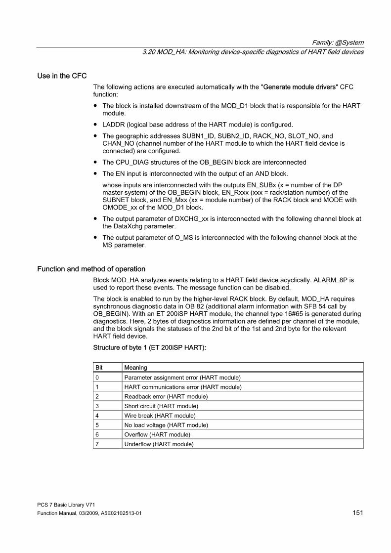
Family: @System 3.20 MOD_HA: Monitoring device-specific diagnostics of HART field devices
PCS 7 Basic Library V71 Function Manual, 03/2009, A5E02102513-01 151
Use in the CFC The following actions are executed automatically with the "Generate module drivers" CFC function: ● The block is installed downstream of the MOD_D1 block that is responsible for the HART
module. ● LADDR (logical base address of the HART module) is configured. ● The geographic addresses SUBN1_ID, SUBN2_ID, RACK_NO, SLOT_NO, and
CHAN_NO (channel number of the HART module to which the HART field device is connected) are configured.
● The CPU_DIAG structures of the OB_BEGIN block are interconnected ● The EN input is interconnected with the output of an AND block.
whose inputs are interconnected with the outputs EN_SUBx (x = number of the DP master system) of the OB_BEGIN block, EN_Rxxx (xxx = rack/station number) of the SUBNET block, and EN_Mxx (xx = module number) of the RACK block and MODE with OMODE_xx of the MOD_D1 block.
● The output parameter of DXCHG_xx is interconnected with the following channel block at the DataXchg parameter.
● The output parameter of O_MS is interconnected with the following channel block at the MS parameter.
Function and method of operation Block MOD_HA analyzes events relating to a HART field device acyclically. ALARM_8P is used to report these events. The message function can be disabled. The block is enabled to run by the higher-level RACK block. By default, MOD_HA requires synchronous diagnostic data in OB 82 (additional alarm information with SFB 54 call by OB_BEGIN). With an ET 200iSP HART module, the channel type 16#65 is generated during diagnostics. Here, 2 bytes of diagnostics information are defined per channel of the module, and the block signals the statuses of the 2nd bit of the 1st and 2nd byte for the relevant HART field device. Structure of byte 1 (ET 200iSP HART): Bit Meaning 0 Parameter assignment error (HART module) 1 HART communications error (HART module) 2 Readback error (HART module) 3 Short circuit (HART module) 4 Wire break (HART module) 5 No load voltage (HART module) 6 Overflow (HART module) 7 Underflow (HART module)

Family: @System 3.20 MOD_HA: Monitoring device-specific diagnostics of HART field devices
PCS 7 Basic Library V71 152 Function Manual, 03/2009, A5E02102513-01
Structure of byte 2 (ET 200iSP HART): Bit Meaning 0 Primary variable outside limits (field device) 1 Secondary variable outside limits (field device) 2 Analog output saturated (field device) 3 Analog output current specified (field device) 4 More statuses available (field device) 5 Reserved for maintenance alarm (field device) 6 Reassignment the field device parameters 7 Malfunction of the field device
For an ET 200M with two-channel HART modules, channel type 16#61 or 16#63 is generated during diagnostics. Bit 5 in byte 8 for channel 0 and byte 9 for channel 1 in the additional alarm information means "HART channel error". If bit 5 = TRUE, the additional diagnostic data is read with SFB 52 (RDREC) as follows: ● with data record 128 for channel 0 ● with data record 129 for channel 1 Diagnostic data records 128 (for channel 0) and 129 (for channel 1) have the same structure. and return detailed HART diagnostic information on the previous transfer. The table below shows the individual error messages/warnings. (Note: The table in the PCS 7 Library manual is clearer and easier to read because the tables have lines, in contrast to the online help.)
Byte/Bit No. 7 6 5 4 3 2 1 0 0: general 1= Mod.
comm. No. of (triggering) client, when module comm. no. =0
Polling address (of HART transducer), always 0 for monodrop
1: fault groups = group error
Channel fault (L+, DrBr)
HART channel fault
HART slave communi-cation
HART command error
device status <> 0 (e.g., configuration changed)
more status Command rejected
0 = Not used
then bytes - 2 8 8 9 - - - 2: HART cf = "communication faults" Field device for module
HART access not possible
parity error in response
overrun error in response
framing error in response
wrong checksum in response
Wrong char timing
too many chars in response
wrong telegram timing
3 to 6: time stamp
Broadcast system time: Milliseconds (10s and 100s), seconds, minutes, and hours in two-digit BCD code. If the timestamp function is not used: Content = 0
7: HART/module last HART or module command 8: HART ce 1
0 "Communication error bits" of "slave", (first status byte) "Command response" list - no errors, but warnings
9: HART ds Device status bits (second status byte)
Two HART status bytes are reserved in the HART protocol to display errors and warnings. These are entered in diagnostic data records 128 and 129 unchanged. The meaning of the HART status bytes is defined in the HART Standard.

Family: @System 3.20 MOD_HA: Monitoring device-specific diagnostics of HART field devices
PCS 7 Basic Library V71 Function Manual, 03/2009, A5E02102513-01 153
● First HART status byte (meaning depends on bit 7): – Bit 7 = 1: Communication error during the transmission of a HART command to the
field device – Bit 7 = 0: Only warnings that the field device sends in response to a command
Bit 7/Bit No. 7 6 5 4 3 2 1 0 Either Bit 7 = 1: HART "communication error" from module to field device
1 parity error in command
overrun error in command
framing error in command
wrong checksum in command
Reserved = 0
too many characters in command (rx buffer overflow)
(undefined)
or Bit 7 = 0: HART "response to a command"
0 The messages in bits 0 - 6 are coded as integers: 0: No command-specific error 1: Undefined 2: Invalid section 3: Transferred parameter too large 4: Transferred parameter too small 5: Too few data bytes received 6: Device-specific command error (rarely used) 7: In write-protected mode 8-15: Various meanings (see code commands) 16: Restricted access 28: Various meanings (see code commands) 32: Device is busy 64: Command not implemented
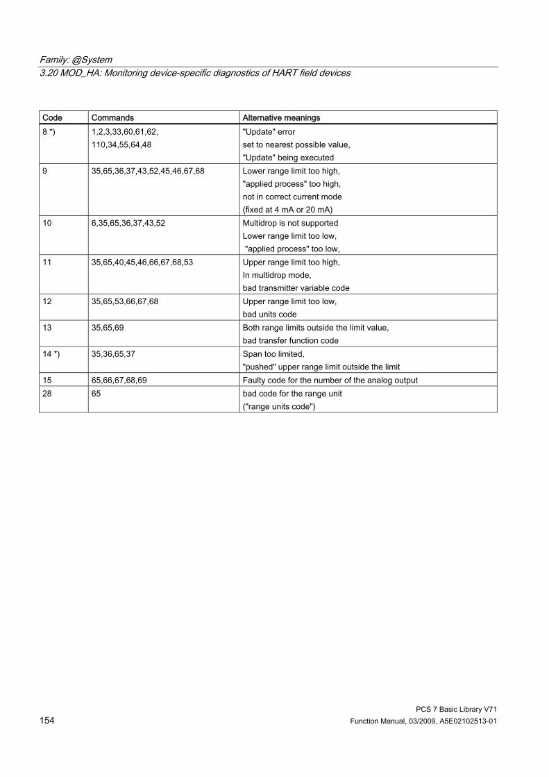
Family: @System 3.20 MOD_HA: Monitoring device-specific diagnostics of HART field devices
PCS 7 Basic Library V71 154 Function Manual, 03/2009, A5E02102513-01
Code Commands Alternative meanings 8 *) 1,2,3,33,60,61,62,
110,34,55,64,48 "Update" error set to nearest possible value, "Update" being executed
9 35,65,36,37,43,52,45,46,67,68 Lower range limit too high, "applied process" too high, not in correct current mode (fixed at 4 mA or 20 mA)
10 6,35,65,36,37,43,52 Multidrop is not supported Lower range limit too low, "applied process" too low,
11 35,65,40,45,46,66,67,68,53 Upper range limit too high, In multidrop mode, bad transmitter variable code
12 35,65,53,66,67,68 Upper range limit too low, bad units code
13 35,65,69 Both range limits outside the limit value, bad transfer function code
14 *) 35,36,65,37 Span too limited, "pushed" upper range limit outside the limit
15 65,66,67,68,69 Faulty code for the number of the analog output 28 65 bad code for the range unit
("range units code")
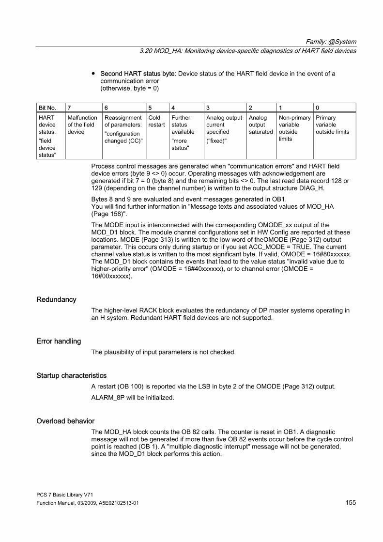
Family: @System 3.20 MOD_HA: Monitoring device-specific diagnostics of HART field devices
PCS 7 Basic Library V71 Function Manual, 03/2009, A5E02102513-01 155
● Second HART status byte: Device status of the HART field device in the event of a communication error (otherwise, byte = 0)
Bit No. 7 6 5 4 3 2 1 0 HART device status: "field device status"
Malfunction of the field device
Reassignment of parameters: "configuration changed (CC)"
Cold restart
Further status available "more status"
Analog output current specified ("fixed)"
Analog output saturated
Non-primary variable outside limits
Primary variable outside limits
Process control messages are generated when "communication errors" and HART field device errors (byte 9 <> 0) occur. Operating messages with acknowledgement are generated if bit 7 = 0 (byte 8) and the remaining bits <> 0. The last read data record 128 or 129 (depending on the channel number) is written to the output structure DIAG_H. Bytes 8 and 9 are evaluated and event messages generated in OB1. You will find further information in "Message texts and associated values of MOD_HA (Page 158)". The MODE input is interconnected with the corresponding OMODE_xx output of the MOD_D1 block. The module channel configurations set in HW Config are reported at these locations. MODE (Page 313) is written to the low word of theOMODE (Page 312) output parameter. This occurs only during startup or if you set ACC_MODE = TRUE. The current channel value status is written to the most significant byte. If valid, OMODE = 16#80xxxxxx. The MOD_D1 block contains the events that lead to the value status "invalid value due to higher-priority error" (OMODE = 16#40xxxxxx), or to channel error (OMODE = 16#00xxxxxx).
Redundancy The higher-level RACK block evaluates the redundancy of DP master systems operating in an H system. Redundant HART field devices are not supported.
Error handling The plausibility of input parameters is not checked.
Startup characteristics A restart (OB 100) is reported via the LSB in byte 2 of the OMODE (Page 312) output. ALARM_8P will be initialized.
Overload behavior The MOD_HA block counts the OB 82 calls. The counter is reset in OB1. A diagnostic message will not be generated if more than five OB 82 events occur before the cycle control point is reached (OB 1). A "multiple diagnostic interrupt" message will not be generated, since the MOD_D1 block performs this action.

Family: @System 3.20 MOD_HA: Monitoring device-specific diagnostics of HART field devices
PCS 7 Basic Library V71 156 Function Manual, 03/2009, A5E02102513-01
Time response Not available
Message functionality MOD_HA reports diagnostic information from a HART field device by means of ALARM_8P or NOTIFY_8P. The message function can be disabled by setting EN_MSG = FALSE.
Operator control and monitoring Note: If you selected the "Enable operator control and monitoring" option in the block object properties in the CFC, the variables transferred to the OS are identified under "I/Os of ..." (OCM column, "+"). Default: Option not activated. If asset management is used in the project and the diagnostic screens have been generated, the faceplate can be called via its block icon. ● Asset management block icons (Page 284) ● Asset management faceplates (Page 286)
Additional information Additional information is available in the sections: Message texts and associated values of MOD_HA (Page 158) Maintenance status of MS (Page 326) You will find more information on this in PCS 7 Advanced Process Library > Basics of APL > General functions of the blocks > Operating, monitoring and reporting > Maintenance release
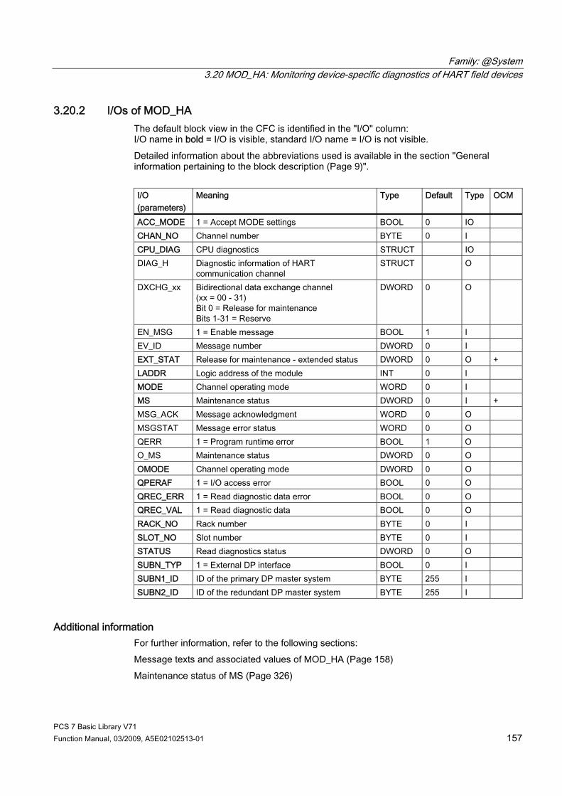
Family: @System 3.20 MOD_HA: Monitoring device-specific diagnostics of HART field devices
PCS 7 Basic Library V71 Function Manual, 03/2009, A5E02102513-01 157
3.20.2 I/Os of MOD_HA The default block view in the CFC is identified in the "I/O" column: I/O name in bold = I/O is visible, standard I/O name = I/O is not visible. Detailed information about the abbreviations used is available in the section "General information pertaining to the block description (Page 9)". I/O (parameters)
Meaning Type Default Type OCM
ACC_MODE 1 = Accept MODE settings BOOL 0 IO CHAN_NO Channel number BYTE 0 I CPU_DIAG CPU diagnostics STRUCT IO DIAG_H Diagnostic information of HART
communication channel STRUCT O
DXCHG_xx Bidirectional data exchange channel (xx = 00 - 31) Bit 0 = Release for maintenance Bits 1-31 = Reserve
DWORD 0 O
EN_MSG 1 = Enable message BOOL 1 I EV_ID Message number DWORD 0 I EXT_STAT Release for maintenance - extended status DWORD 0 O + LADDR Logic address of the module INT 0 I MODE Channel operating mode WORD 0 I MS Maintenance status DWORD 0 I + MSG_ACK Message acknowledgment WORD 0 O MSGSTAT Message error status WORD 0 O QERR 1 = Program runtime error BOOL 1 O O_MS Maintenance status DWORD 0 O OMODE Channel operating mode DWORD 0 O QPERAF 1 = I/O access error BOOL 0 O QREC_ERR 1 = Read diagnostic data error BOOL 0 O QREC_VAL 1 = Read diagnostic data BOOL 0 O RACK_NO Rack number BYTE 0 I SLOT_NO Slot number BYTE 0 I STATUS Read diagnostics status DWORD 0 O SUBN_TYP 1 = External DP interface BOOL 0 I SUBN1_ID ID of the primary DP master system BYTE 255 I SUBN2_ID ID of the redundant DP master system BYTE 255 I
Additional information For further information, refer to the following sections: Message texts and associated values of MOD_HA (Page 158) Maintenance status of MS (Page 326)
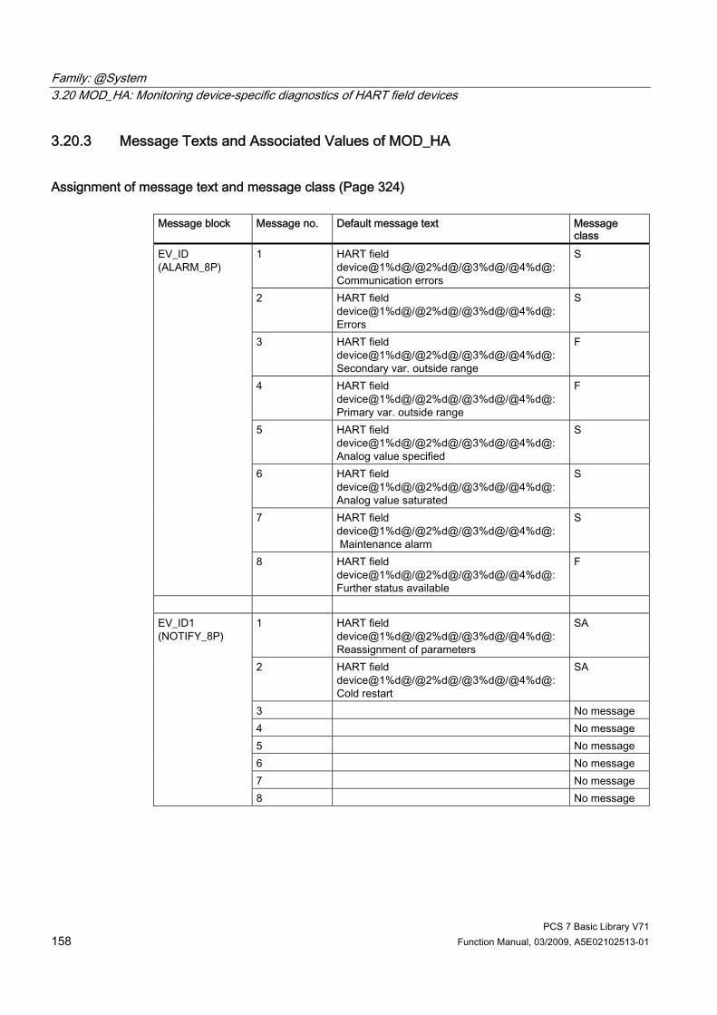
Family: @System 3.20 MOD_HA: Monitoring device-specific diagnostics of HART field devices
PCS 7 Basic Library V71 158 Function Manual, 03/2009, A5E02102513-01
3.20.3 Message Texts and Associated Values of MOD_HA
Assignment of message text and message class (Page 324) Message block Message no. Default message text Message
class 1 HART field
device@1%d@/@2%d@/@3%d@/@4%d@: Communication errors
S
2 HART field device@1%d@/@2%d@/@3%d@/@4%d@: Errors
S
3 HART field device@1%d@/@2%d@/@3%d@/@4%d@: Secondary var. outside range
F
4 HART field device@1%d@/@2%d@/@3%d@/@4%d@: Primary var. outside range
F
5 HART field device@1%d@/@2%d@/@3%d@/@4%d@: Analog value specified
S
6 HART field device@1%d@/@2%d@/@3%d@/@4%d@: Analog value saturated
S
7 HART field device@1%d@/@2%d@/@3%d@/@4%d@: Maintenance alarm
S
EV_ID (ALARM_8P)
8 HART field device@1%d@/@2%d@/@3%d@/@4%d@: Further status available
F
1 HART field
device@1%d@/@2%d@/@3%d@/@4%d@: Reassignment of parameters
SA
2 HART field device@1%d@/@2%d@/@3%d@/@4%d@: Cold restart
SA
3 No message 4 No message 5 No message 6 No message 7 No message
EV_ID1 (NOTIFY_8P)
8 No message

Family: @System 3.20 MOD_HA: Monitoring device-specific diagnostics of HART field devices
PCS 7 Basic Library V71 Function Manual, 03/2009, A5E02102513-01 159
Assignment of associated values Message block ALARM_8P
Associated value
Block parameter
Meaning
1 SUBN_ID DP master system ID (byte) 2 RACK_NO Rack/station number (byte) 3 SLOT_NO Slot number (byte)
EV_ID
4 CHAN_NO Channel error text number
1 SUBN_ID DP master system ID (byte) 2 RACK_NO Rack/station number 3 SLOT_NO
EV_ID1
4 CHAN_NO
If SUBN1_ID = 16#FF, the associated value is substituted with SUBN2_ID.

Family: @System 3.21 MOD_MS: Monitoring up to 16 channels on ET 200S/X motor starter modules with diagnostic functions
PCS 7 Basic Library V71 160 Function Manual, 03/2009, A5E02102513-01
3.21 MOD_MS: Monitoring up to 16 channels on ET 200S/X motor starter modules with diagnostic functions
3.21.1 Description of MOD_MS
Object name (type + number) FB 96 ● MOD_MS block I/Os (Page 165)
Area of application The MOD_MS block the up to 16-channel motor starter modules with diagnostic capability (ET 200S). H systems support only the modules installed in switched racks.
Calling OBs The block must be installed in the run sequence in the following OBs: OB 1 Cyclic program OB 82 Diagnostic interrupt OB 83 Insert/remove module interrupt OB 85 Program runtime error OB 86 Rack failure OB 100 Warm restart
Use in the CFC The following actions are executed automatically with the "Generate module drivers" CFC function: ● The MOD_MS block is installed in its runtime group downstream of the RACK block
runtime group in the above-mentioned OBs. ● The MODE_xx, SUBN1_ID, SUBN2_ID, and SUBN_TYP inputs are configured. ● The logical addresses LADDR and LADDR1 are configured. ● The OUT structures CPU_DIAG of the OB_BEGIN block and RAC_DIAG of the RACK
block are interconnected with the IN_OUT structures of the same name of MOD_MS. ● The output parameter of DXCHG_xx is interconnected with the following channel block at
the DataXchg parameter. ● The output parameter of O_MS is interconnected with the following channel block at the
MS parameter.

Family: @System 3.21 MOD_MS: Monitoring up to 16 channels on ET 200S/X motor starter modules with diagnostic functions
PCS 7 Basic Library V71 Function Manual, 03/2009, A5E02102513-01 161
Function and method of operation Block MOD_MS analyzes all events that affect a module and its channels acyclically. It generates a channel-specific MODE (Page 313) and value status for the signal processing blocks. ALARM_8P is used to report these events. The message function can be disabled. The block is enabled to run by the higher-level RACK block. The event to be evaluated is stored in the CPU_DIAG start and diagnostic information of the OB_BEGIN block. There is a MODE_xx input for each signal channel of the module. The module channel configuration data created in HW Config is reported here. The function writes MODE_xx to the low word of the OMODE_xx (Page 312) output parameter. This occurs only during startup or if you set ACC_MODE = TRUE. The current channel value status is written to the most significant byte. If the result is positive, the system sets OMODE_xx = 16#80xxxxxx. The following events will lead to the value status "invalid value due to higher-level error" (OMODE_xx = 16#40xxxxxx): ● Events that are evaluated by the RACK block:
– Rack failure (OB 86) (output parameter QRACKF = TRUE) – Program execution error (OB 85) (output parameter QRACKF = TRUE)
● Events that are evaluated by the MOD block: – Program execution error (OB 85) (output parameter QPERAF = TRUE) – Module removed (OB 83) (output parameter QMODF = TRUE) – Diagnostic interrupt (OB 82)
The following events in OB 82 will lead to a module error, and are indicated with 16#40xxxxxx ("higher-priority error") in OMODE. At the same time, output parameter QMODF = TRUE: ● Configuration/parameter assignment error ● Overload ● Short circuit ● Error ● Actuator OFF ● Wire break ● Safety-related shutdown ● High limit overshot ● Low limit undershot ● Missing supply voltage ● Switching element overload ● External error
Family: @System 3.21 MOD_MS: Monitoring up to 16 channels on ET 200S/X motor starter modules with diagnostic functions
PCS 7 Basic Library V71 162 Function Manual, 03/2009, A5E02102513-01
ALARM_8P is used to report "module removed", "I/O access error", and the above "OB 82 error" events to WinCC. The system verifies during startup that the module is available (plugged in). The module status information that is read here is then available in the form of service output parameters (MOD_INF). Detailed information about the faults is entered in the DIAG_INF output parameter of data type STRUCT. You will find further information in the "Service Information" section, and in theSystem Software for S7-300/400 System and Standard Functions; Diagnostic Data, Byte 0 to Byte 8, Structure of Channel-Specific Diagnostic Data reference manual.
Redundancy The block supports segment redundancy of CPU 417H for distributed I/Os. To use this function, you must configure the SUBN1_ID (connection to CPU 0) and SUBN2_ID (connection to CPU 1) inputs with the numbers of the redundant segments. If there is no segment redundancy, the remaining input must be set to the (default) value 16#FF.
MODE setting You will find more information about this in the "OMODE settings (Page 313)" section.
Note If you change the parameter settings for the MODE_xx inputs at runtime, these changes will not be accepted at the outputs until the ACC_MODE is set to 1.
OMODE Structure You will find further information in the "OMODE (Page 312)" section.
Valid channel display The existing channels on a module are displayed in the CH_EXIST output by setting a bit in the DWORD, starting at bit 0, for every existing channel. If the bit assigned to a channel = 0, the channel is not available. Output CH_OK displays the valid channels on a module by setting a bit to TRUE for every valid channel, where bit 0 is assigned to channel 0, etc. If the bit assigned to a channel is 0, the channel is faulty. If a module error occurs, all channels are disrupted.
Addressing You will find further information in the "Addressing (Page 323)" section.
Family: @System 3.21 MOD_MS: Monitoring up to 16 channels on ET 200S/X motor starter modules with diagnostic functions
PCS 7 Basic Library V71 Function Manual, 03/2009, A5E02102513-01 163
Error handling The plausibility of input parameters is not checked. You will find more information about this in "Error information of output parameter MSG_STAT (Page 322)".
Service Information To analyze faults, the module status information entered during startup is read via the MOD_INF structured output parameter. You will find more information about this in the reference manual System Software for S7-300/400 System and Standard Functions; System Status List, Module Status Information. Following a diagnostic interrupt, you will also find detailed module diagnostic information in the MODDIAG0 to MODDIAG8 output parameters. You will find more information in the reference manual System Software for S7-300/400 System and Standard Functions; Diagnostic Data, Byte 0 to Byte 10. The CHDIAG00 to CHDIAG15 output parameters contain detailed channel-status information. You will find more information in the reference manual System Software for S7-300/400 System and Standard Functions; Structure of Channel-Specific Diagnostic Data. Of the motor starter module channels, only channel 0 is assigned the diagnostic function. The error code is stored in CHDIAG00 to CHDIAG03. You will find further information about this in the ET 200S, Motor Starter Safety Technology SIGUARD; Diagnostics and Monitoring via the User Program reference manual. The system resets this diagnostic information after a diagnostic interrupt has been reported outgoing (no further channel or module errors are queued).
Startup characteristics After a restart/initial startup, the system verifies that the module is available under its logical base address. A restart (OB100) is reported via the LSB in byte 2 of the OMODE_xx (Page 312) outputs.
Time response Not available
Message functionality MOD_MS reports module and motor-starter errors by means of ALARM_8P_1 and ALARM_8P_2. The DELAY1 and DELAY2 inputs are used to delay the I/O access error message. DELAY1 allows you to enter a time in seconds for which the block will wait for a higher-priority error (rack failure or removal/insertion) following a program execution error (OB 85) before it outputs the message. DELAY2 determines the number of seconds the block waits after the higher-priority error has been reported outgoing until it outputs the queued I/O access error as well. Both values are set to 2 seconds by default.

Family: @System 3.21 MOD_MS: Monitoring up to 16 channels on ET 200S/X motor starter modules with diagnostic functions
PCS 7 Basic Library V71 164 Function Manual, 03/2009, A5E02102513-01
Operator control and monitoring Note: If you selected the "Enable operator control and monitoring" option in the block object properties in the CFC, the variables transferred to the OS are identified under "I/Os of ..." (OCM column, "+"). Default: Option not activated. If asset management is used in the project and the diagnostic screens have been generated, the faceplate can be called via its block icon. ● Asset management block icons (Page 284) ● Asset management faceplates (Page 286)
Additional information For further information, refer to the following sections: Message texts and associated values of MOD_MS (Page 167) Maintenance status of MS (Page 326) You will find more information on this in PCS 7 Advanced Process Library > Basics of APL > General functions of the blocks > Operating, monitoring and reporting > Maintenance release

Family: @System 3.21 MOD_MS: Monitoring up to 16 channels on ET 200S/X motor starter modules with diagnostic functions
PCS 7 Basic Library V71 Function Manual, 03/2009, A5E02102513-01 165
3.21.2 I/Os of MOD_MS The factory setting of the block display in the CFC is identified in the "I/O" column: I/O name bold = I/O visible, I/O name normal = I/O not visible. You will find explanations of and information about the abbreviations used in "General information about the block description (Page 9)". I/O (parameters)
Meaning Data type Default Type O&M
ACC_MODE 1 = accept MODE settings BOOL 0 IO CH_EXIST Channel exists DWORD 0 O + CH_OK Channel OK DWORD 0 O + CPU_DIAG System structure: CPU diagnostics STRUCT IO DELAY1 Alarm delay 1 (s) INT 2 I DELAY2 Alarm delay 2 (s) INT 2 I DIAG_INF System structure: Diagnostic information STRUCT O DXCHG_xx Bidirectional data exchange channel
(xx = 00 - 31) Bit 0 = Release for maintenance Bit 1-31 = Reserve
DWORD 0 O
EN_MSG 1 = enable message BOOL 1 I EV_IDx Message number x DWORD 0 I EXT_STAT Release for maintenance - extended status DWORD 0 O + LADDR Logical address of the input channels INT 0 I LADDR1 Logical address of the output channels INT 0 I MOD_INF System structure: Module parameter STRUCT O MODE_xx Channel xx mode WORD 0 I MS Maintenance status DWORD 0 I + MSG_ACKx Message acknowledgment x WORD 0 O MSGSTATx Message error information x WORD 0 O O_MS Maintenance status DWORD 0 O OMODE_xx Channel xx mode DWORD 0 O QERR 1 = program error BOOL 1 O QMODF 1 = module removed/defective BOOL 0 O QPERAF 1 = I/O access error BOOL 0 O QRACKF 1 = failure of the rack BOOL 0 O RAC_DIAG System structure: Rack diagnostics STRUCT IO RACK_NO Rack number BYTE 0 I SLOT_NO Slot number BYTE 0 I SUBN_TYP 1 = external DP interface BOOL 0 I SUBN1_ID ID of the primary DP master system BYTE 255 I SUBN2_ID ID of the redundant DP master system BYTE 255 I

Family: @System 3.21 MOD_MS: Monitoring up to 16 channels on ET 200S/X motor starter modules with diagnostic functions
PCS 7 Basic Library V71 166 Function Manual, 03/2009, A5E02102513-01
Additional information For further information, refer to the following sections: Message texts and associated values of MOD_MS (Page 167) Maintenance status of MS (Page 326)
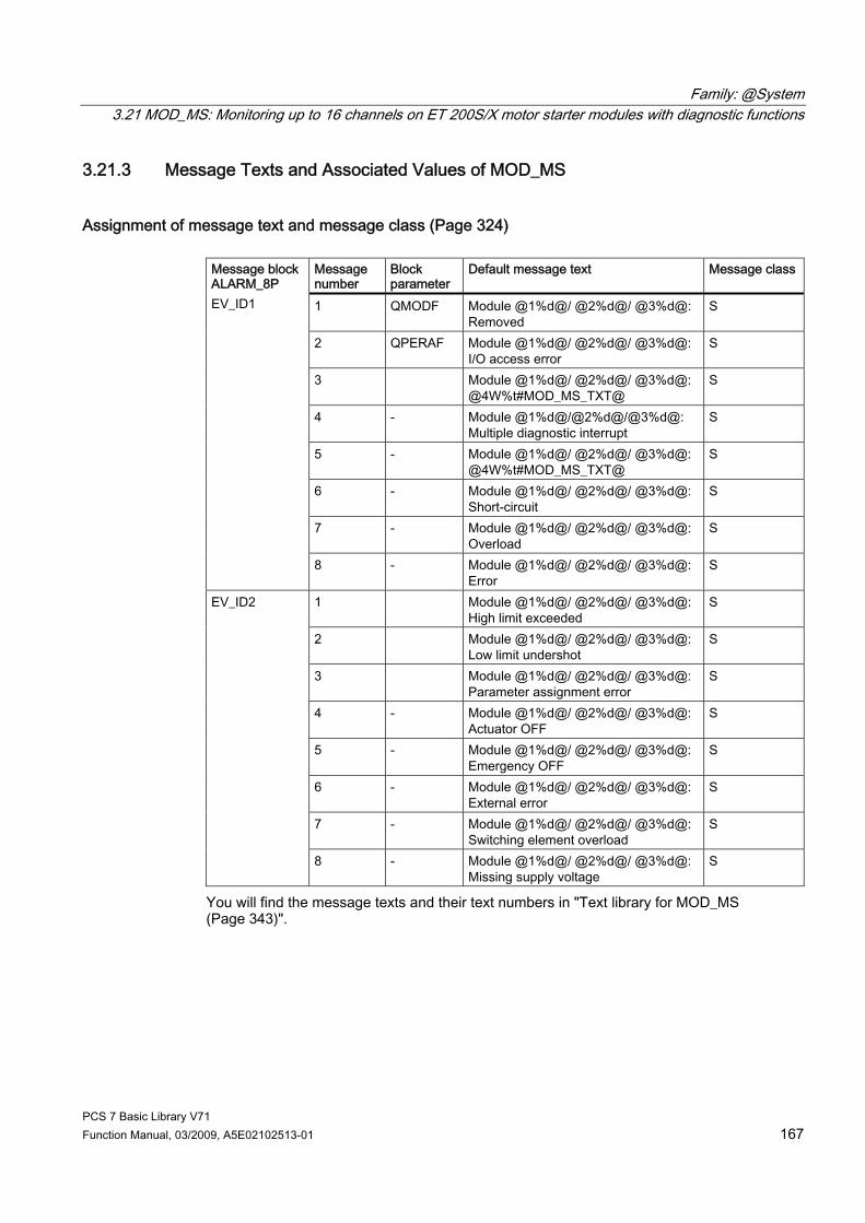
Family: @System 3.21 MOD_MS: Monitoring up to 16 channels on ET 200S/X motor starter modules with diagnostic functions
PCS 7 Basic Library V71 Function Manual, 03/2009, A5E02102513-01 167
3.21.3 Message Texts and Associated Values of MOD_MS
Assignment of message text and message class (Page 324)
Message number
Block parameter
Default message text Message class
1 QMODF Module @1%d@/ @2%d@/ @3%d@: Removed
S
2 QPERAF Module @1%d@/ @2%d@/ @3%d@: I/O access error
S
3 Module @1%d@/ @2%d@/ @3%d@: @4W%t#MOD_MS_TXT@
S
4 - Module @1%d@/@2%d@/@3%d@: Multiple diagnostic interrupt
S
5 - Module @1%d@/ @2%d@/ @3%d@: @4W%t#MOD_MS_TXT@
S
6 - Module @1%d@/ @2%d@/ @3%d@: Short-circuit
S
7 - Module @1%d@/ @2%d@/ @3%d@: Overload
S
Message block ALARM_8P EV_ID1
8 - Module @1%d@/ @2%d@/ @3%d@: Error
S
1 Module @1%d@/ @2%d@/ @3%d@: High limit exceeded
S
2 Module @1%d@/ @2%d@/ @3%d@: Low limit undershot
S
3 Module @1%d@/ @2%d@/ @3%d@: Parameter assignment error
S
4 - Module @1%d@/ @2%d@/ @3%d@: Actuator OFF
S
5 - Module @1%d@/ @2%d@/ @3%d@: Emergency OFF
S
6 - Module @1%d@/ @2%d@/ @3%d@: External error
S
7 - Module @1%d@/ @2%d@/ @3%d@: Switching element overload
S
EV_ID2
8 - Module @1%d@/ @2%d@/ @3%d@: Missing supply voltage
S
You will find the message texts and their text numbers in "Text library for MOD_MS (Page 343)".
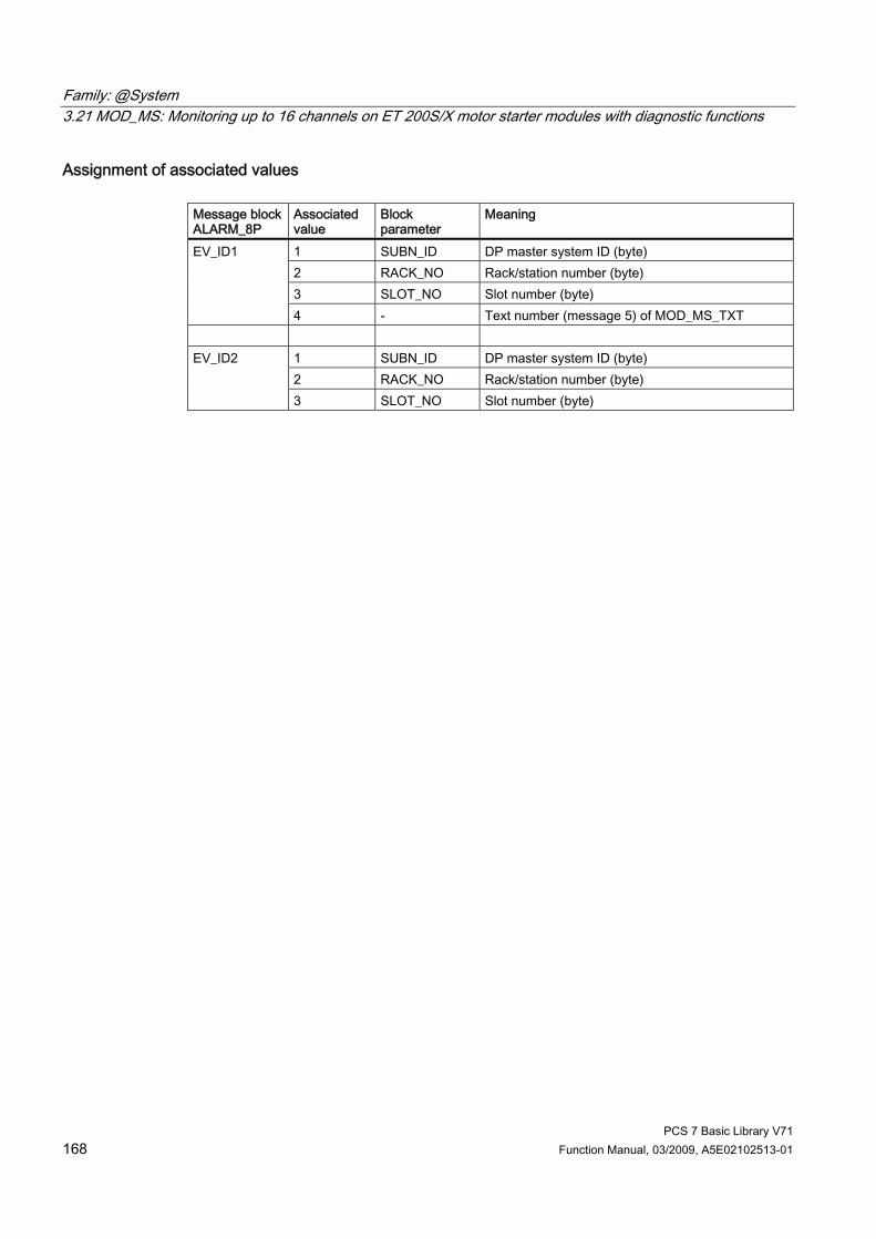
Family: @System 3.21 MOD_MS: Monitoring up to 16 channels on ET 200S/X motor starter modules with diagnostic functions
PCS 7 Basic Library V71 168 Function Manual, 03/2009, A5E02102513-01
Assignment of associated values Message block ALARM_8P
Associated value
Block parameter
Meaning
1 SUBN_ID DP master system ID (byte) 2 RACK_NO Rack/station number (byte) 3 SLOT_NO Slot number (byte)
EV_ID1
4 - Text number (message 5) of MOD_MS_TXT
1 SUBN_ID DP master system ID (byte) 2 RACK_NO Rack/station number (byte)
EV_ID2
3 SLOT_NO Slot number (byte)
Family: @System 3.22 MOD_PAL0: Diagnosing a DPV0 PA slave (via DP/PA coupler downstream of a DP/PA link DPV1)
PCS 7 Basic Library V71 Function Manual, 03/2009, A5E02102513-01 169
3.22 MOD_PAL0: Diagnosing a DPV0 PA slave (via DP/PA coupler downstream of a DP/PA link DPV1)
3.22.1 Description of MOD_PAL0
Object name (type + number) FB 99 ● MOD_PAL0 block I/Os (Page 172)
Area of application Block MOD_PAL0 reports the maintenance status of a PA field device that is used as a DPV0 slave downstream of a DP/PA link DPV1. The PA field devices must conform to the PROFIBUS V3.0 profile.
Calling OBs The cyclic OB and OB 100.
Use in the CFC The following actions are executed automatically with the "Generate module drivers" CFC function: ● The block is integrated in the run sequence upstream of block PA_x ● The SUBN1_ID, SUBN2_ID, RACK_NO, SLOT_NO, PADP_ADR, PROF_V30 inputs are
configured. ● The block inputs are interconnected with the following outputs:
– Output PA_DIAG of block PADP_L10 – OMODEx outputs of block PADP_L10 – QMODF and QPERAF outputs of block PADP_L10 – with output structure RAC_DIAG of block OB_DIAG1 – input QC_x with PA field device icon
● The output parameter of DXCHG_xx is interconnected with the following channel block at the DataXchg parameter.
● The output parameter of O_MS is interconnected with the following channel block at the MS parameter.
Note The CFC function "Generate module drivers" can only be used if the PA field device belongs to slave family 12.
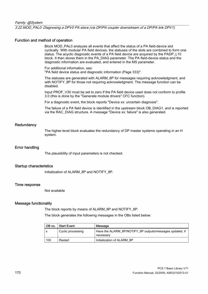
Family: @System 3.22 MOD_PAL0: Diagnosing a DPV0 PA slave (via DP/PA coupler downstream of a DP/PA link DPV1)
PCS 7 Basic Library V71 170 Function Manual, 03/2009, A5E02102513-01
Function and method of operation Block MOD_PAL0 analyzes all events that affect the status of a PA field-device slot cyclically. With modular PA field devices, the statuses of the slots are combined to form one status. The acyclic diagnostic events of a PA field device are acquired by the PADP_L10 block. It then stores them in the PA_DIAG parameter. The PA field-device status and the diagnostic information are evaluated, and entered in the MS parameter. For additional information, see: "PA field device status and diagnostic information (Page 333)". The statuses are generated with ALARM_8P for messages requiring acknowledgment, and with NOTIFY_8P for those not requiring acknowledgment. The message function can be disabled. Input PROF_V30 must be set to zero if the PA field device used does not conform to profile 3.0 (this is done by the "Generate module drivers" CFC function). For a diagnostic event, the block reports "Device xx: uncertain diagnosis". The failure of a PA field device is identified in the upstream block OB_DIAG1, and is reported via the RAC_DIAG structure. A message "Device xx: failure" is also generated.
Redundancy The higher-level block evaluates the redundancy of DP master systems operating in an H system.
Error handling The plausibility of input parameters is not checked.
Startup characteristics Initialization of ALARM_8P and NOTIFY_8P.
Time response Not available
Message functionality The block reports by means of ALARM_8P and NOTIFY_8P. The block generates the following messages in the OBs listed below: OB no. Start Event Message x Cyclic processing Have the ALARM_8P/NOTIFY_8P outputs/messages updated, if
necessary 100 Restart Initialization of ALARM_8P
Family: @System 3.22 MOD_PAL0: Diagnosing a DPV0 PA slave (via DP/PA coupler downstream of a DP/PA link DPV1)
PCS 7 Basic Library V71 Function Manual, 03/2009, A5E02102513-01 171
Operator control and monitoring Note: If you selected the "Enable operator control and monitoring" option in the block object properties in the CFC, the variables transferred to the OS are identified under "I/Os of ..." (OCM column, "+"). Default: Option not activated. If asset management is used in the project and the diagnostic screens have been generated, the faceplate can be called via its block icon. ● Asset management block icons (Page 284) ● Asset management faceplates (Page 286)
Additional information For further information, refer to the following sections: Message texts and associated values for MOD_PAL0 (Page 174) Maintenance status of MS (Page 326) You will find more information on this in PCS 7 Advanced Process Library > Basics of APL > General functions of the blocks > Operating, monitoring and reporting > Maintenance release

Family: @System 3.22 MOD_PAL0: Diagnosing a DPV0 PA slave (via DP/PA coupler downstream of a DP/PA link DPV1)
PCS 7 Basic Library V71 172 Function Manual, 03/2009, A5E02102513-01
3.22.2 I/Os of MOD_PAL0
I/Os The default block view in the CFC is identified in the "I/O" column: I/O name in bold = I/O is visible, standard I/O name = I/O is not visible. You will find explanations of, and information about the abbreviations used in "General information about the block description (Page 9)". I/O
Meaning
Type
Preset Type
O&M
B_QC Bit-granular Σ status (channel 0 to 15) of the PA field device
STRUCT O
DXCHG_xx Bidirectional data exchange channel (xx = 00 - 31)
DWORD 0 O
CH_EXIST Channel exists DWORD 0 O + CH_OK Channel OK DWORD 0 O + DXCHG_xx Bidirectional data exchange channel
Bit 0 = Release for maintenance Bits 1-31 = Reserve
DWORD 0 O
EN_DIAG 1 = Queued diagnostic event BOOL 0 I EN_MSG 1 = enable message BOOL 1 I EV_IDx Message number x DWORD 0 I EXT_STAT Release for maintenance - extended status DWORD 0 O + MODE_x Value status PA field device (x = channel 0 to
15) DWORD 0 I
MODF 1 = PA slave error BOOL 0 I MS Maintenance status DWORD 0 I + MSG_ACKx Message acknowledgment x WORD 0 O MSGSTATx Message error information x WORD 0 O O_MS Maintenance status DWORD 0 O OMODE_x Value status PA field device (x = channel 0 to
15) DWORD 0 O
PA_DIAG PA field device diagnostic information DWORD 0 I PADP_ADR Address of the PA field device BYTE 0 I PERAF 1 = I/O access error BOOL 0 I PROF_V30 1 = PA slave profile V3.0 BOOL 0 I QC_x Status of PA field device (x = channel 0 to 15) BYTE 0 I QERR 1 = program error BOOL 1 O QMODF 1 = PA slave error BOOL 0 O QPERAF 1 = I/O access error BOOL 0 O QRACKF 1 = PA slave/DP master error BOOL 0 O RAC_DIAG System structure: RACK diagnostics STRUCT 0 IO RACK_NO Number of the DP link BYTE 0 I

Family: @System 3.22 MOD_PAL0: Diagnosing a DPV0 PA slave (via DP/PA coupler downstream of a DP/PA link DPV1)
PCS 7 Basic Library V71 Function Manual, 03/2009, A5E02102513-01 173
I/O
Meaning
Type
Preset Type
O&M
SLOT_NO Slot number of the PA field device in the DP link
BYTE 0 I
SUBN1_ID ID of the primary DP master system BYTE 255 I SUBN2_ID ID of the redundant DP master system BYTE 255 I
Additional information For further information, refer to the following sections: Message texts and associated values for MOD_PAL0 (Page 174) Maintenance status of MS (Page 326) PA field device status and diagnostic information (Page 333)

Family: @System 3.22 MOD_PAL0: Diagnosing a DPV0 PA slave (via DP/PA coupler downstream of a DP/PA link DPV1)
PCS 7 Basic Library V71 174 Function Manual, 03/2009, A5E02102513-01
3.22.3 Message Texts and Associated Values of MOD_PAL0
Assignment of message text and message class (Page 324) Message block
Message no.
Default message text
Message class
1 Device @1%d@/ @2%d@/@3%d@: Bad, maintenance alarm
S
2 Device @1%d@/ @2%d@/@3%d@: Uncertain, maintenance request
F
3 Device @1%d@/ @2%d@/@3%d@: Good, maintenance required
M
4 Device @1%d@/ @2%d@/@3%d@: I/O access error
S
5 Device @1%d@/ @2%d@/@3%d@: Uncertain diagnostics
S
6 Device @1%d@/ @2%d@/@3%d@: Failure S 7 No message
EV_ID1 (ALARM_8P)
8 No message
1 Device @1%d@/ @2%d@/@3%d@: Good, changes to fail-safe position
SA
2 Device @1%d@/ @2%d@/@3%d@: Good, configuration change made
SA
3 Device @1%d@/ @2%d@/@3%d@: Uncertain, simulation
SA
4 Device @1%d@/ @2%d@/@3%d@: Uncertain, due to process, no maintenance
SA
5 Device @1%d@/ @2%d@/@3%d@: Bad, due to process, no maintenance
SA
6 Device @1%d@/ @2%d@/@3%d@: Bad, local operator control/function test
SA
7 Device @1%d@/ @2%d@/@3%d@: Bad, out of service
SA
EV_ID2 (NOTIFY_8P)
8 Device @1%d@/ @2%d@/@3%d@: @4W%t#MOD_PAL0_TXT@
SA
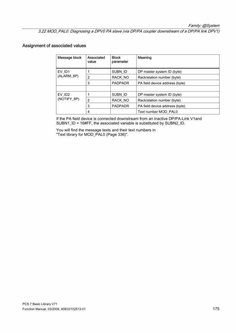
Family: @System 3.22 MOD_PAL0: Diagnosing a DPV0 PA slave (via DP/PA coupler downstream of a DP/PA link DPV1)
PCS 7 Basic Library V71 Function Manual, 03/2009, A5E02102513-01 175
Assignment of associated values Message block Associated
value
Block parameter
Meaning
1 SUBN_ID DP master system ID (byte) 2 RACK_NO Rack/station number (byte)
EV_ID1 (ALARM_8P)
3 PADPADR PA field device address (byte)
1 SUBN_ID DP master system ID (byte) 2 RACK_NO Rack/station number (byte) 3 PADPADR PA field device address (byte)
EV_ID2 (NOTIFY_8P)
4 Text number MOD_PAL0
If the PA field device is connected downstream from an inactive DP/PA-Link V1and SUBN1_ID = 16#FF, the associated variable is substituted by SUBN2_ID. You will find the message texts and their text numbers in "Text library for MOD_PAL0 (Page 336)".
Family: @System 3.23 MOD_PAX0: Diagnosing a DPV0 PA slave (via DP/PA coupler with connection to a DP master system)
PCS 7 Basic Library V71 176 Function Manual, 03/2009, A5E02102513-01
3.23 MOD_PAX0: Diagnosing a DPV0 PA slave (via DP/PA coupler with connection to a DP master system)
3.23.1 Description of MOD_PAX0
Object name (type + number) FB 112 ● MOD_PAX0 block I/Os (Page 179)
Area of application Block MOD_PAX0 reports the maintenance status of a PA field device that is used as a DPV0 slave in a DP master system. The PA field devices must conform to the PROFIBUS V3.0 profile.
Calling OBs The cyclic OB and OB 100.
Use in the CFC The following actions are executed automatically with the "Generate module drivers" CFC function: ● The block is integrated in the run sequence upstream of the PA_x block. ● The inputs SUBN1_ID, SUBN2_ID, PADP_ADR and PROF_V30 have parameters
assigned. ● The inputs are interconnected with the following outputs:
– Output PA_DIAG of block PADP_L10 – OMODEx outputs of block PADP_L10 – QMODF and QPERAF outputs of block PADP_L10 – with output structure RAC_DIAG of block OB_DIAG1

Family: @System 3.23 MOD_PAX0: Diagnosing a DPV0 PA slave (via DP/PA coupler with connection to a DP master system)
PCS 7 Basic Library V71 Function Manual, 03/2009, A5E02102513-01 177
● Input QC_x is interconnected with the PA field device status icon. ● Output OMODExx is interconnected with the MODE input of the PA_x block. ● The output parameter of DXCHG_xx is interconnected with the following channel block at
the DataXchg parameter. ● The output parameter of O_MS is interconnected with the following channel block at the
MS parameter.
Note The CFC function "Generate module drivers" can only be used if the PA field device belongs to slave family 12.
Function and method of operation Block MOD_PAX0 analyzes all events relating to the status of a PA field device slot cyclically. With modular PA field devices, the statuses of the slots are combined to form one status. The acyclic diagnostic events of a PA field device are acquired by the PADP_L10 block. It then stores them in the PA_DIAG parameter. The PA field-device status and the diagnostic information are evaluated, and entered in the MS parameter. You will find further in the "PA field device status and diagnostic information (Page 333)" section. Input PROF_V30 must be set to zero if the PA field device used does not conform to profile 3.0 (this is done by the "Generate module drivers" CFC function). In the event of a diagnostic event, the block reports "PA field device diagnostics". There is an input (MODE_xx (Page 313)) for each slot (module) on the PA field device that is used to read in configuration settings made for the PA field device slots (module) in HW Config.. The function writes MODE_xx to the low word of the OMODE_xx (Page 312) output parameter. This occurs only during startup or if you set ACC_MODE = TRUE. The current slot value status is written to the most significant byte. If the result is positive, the system sets OMODE_xx = 16#80xxxxxx. The following events lead to the value status "Invalid value due to higher-priority error" (OMODE_xx = 16#40xxxxxx):
MODE setting for PA profiles You will find further information in "PA_MODE settings (Page 320)".
Note If you change the parameter settings for the MODE_xx inputs at runtime, these changes will not be accepted at the outputs until the ACC_MODE is set to 1.
OMODE Structure You will find further information in the "OMODE (Page 312)" section.

Family: @System 3.23 MOD_PAX0: Diagnosing a DPV0 PA slave (via DP/PA coupler with connection to a DP master system)
PCS 7 Basic Library V71 178 Function Manual, 03/2009, A5E02102513-01
Redundancy The higher-level block evaluates the redundancy of DP master systems operating in an H system.
Error handling The plausibility of input parameters is not checked.
Startup characteristics Initialization of ALARM_8P and NOTIFY_8P
Time response Not available
Message functionality The block uses ALARM_8P and NOTIFY_8P The block generates the following messages in the OBs listed below: OB no. Start Event Message x Cyclic processing Repeat the update of ALARM_8P outputs/messages, if
necessary 100 Restart Initialization of ALARM_8P
Operator control and monitoring Note: If you selected the "Enable operator control and monitoring" option in the block object properties in the CFC, the variables transferred to the OS are identified under "I/Os of ..." (OCM column, "+"). Default: Option not activated. If asset management is used in the project and the diagnostic screens have been generated, the faceplate can be called via its block icon. ● Asset management block icons (Page 284) ● Asset management faceplates (Page 286)
Additional information For further information, refer to the following sections: Message texts and associated values for MOD_PAX0 (Page 181) Maintenance status of MS (Page 326) You will find more information on this in PCS 7 Advanced Process Library > Basics of APL > General functions of the blocks > Operating, monitoring and reporting > Maintenance release
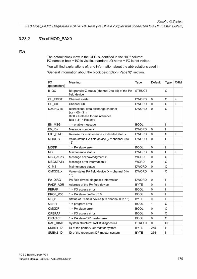
Family: @System 3.23 MOD_PAX0: Diagnosing a DPV0 PA slave (via DP/PA coupler with connection to a DP master system)
PCS 7 Basic Library V71 Function Manual, 03/2009, A5E02102513-01 179
3.23.2 I/Os of MOD_PAX0
I/Os The default block view in the CFC is identified in the "I/O" column: I/O name in bold = I/O is visible, standard I/O name = I/O is not visible. You will find explanations of, and information about the abbreviations used in "General information about the block description (Page 9)" section. I/O (parameters)
Meaning
Type
Default Type
O&M
B_QC Bit-granular Σ status (channel 0 to 15) of the PA field device
STRUCT O
CH_EXIST Channel exists DWORD 0 O + CH_OK Channel OK DWORD 0 O + DXCHG_xx Bidirectional data exchange channel
(xx = 00 - 31) Bit 0 = Release for maintenance Bits 1-31 = Reserve
DWORD 0 O
EN_MSG 1 = enable message BOOL 1 I EV_IDx Message number x DWORD 0 I EXT_STAT Release for maintenance - extended status DWORD 0 O + MODE_x Value status PA field device (x = channel 0 to
15) DWORD 0 I
MODF 1 = PA slave error BOOL 0 I MS Maintenance status DWORD 0 I + MSG_ACKx Message acknowledgment x WORD 0 O MSGSTATx Message error information x WORD 0 O O_MS Maintenance status DWORD 0 O OMODE_x Value status PA field device (x = channel 0 to
15) DWORD 0 O
PA_DIAG PA field device diagnostic information DWORD 0 I PADP_ADR Address of the PA field device BYTE 0 I PERAF 1 = I/O access error BOOL 0 I PROF_V30 1 = PA slave profile V3.0 BOOL 0 I QC_x Status of PA field device (x = channel 0 to 15) BYTE 0 I QERR 1 = program error BOOL 1 O QMODF 1 = PA slave error BOOL 0 O QPERAF 1 = I/O access error BOOL 0 O QRACKF 1 = PA slave/DP master error BOOL 0 O RAC_DIAG System structure: RACK diagnostics STRUCT 0 IO SUBN1_ID ID of the primary DP master system BYTE 255 I SUBN2_ID ID of the redundant DP master system BYTE 255 I

Family: @System 3.23 MOD_PAX0: Diagnosing a DPV0 PA slave (via DP/PA coupler with connection to a DP master system)
PCS 7 Basic Library V71 180 Function Manual, 03/2009, A5E02102513-01
Additional information For further information, refer to the following sections: Message texts and associated values for MOD_PAX0 (Page 181) Maintenance status of MS (Page 326) PA field device status and diagnostic information (Page 333)

Family: @System 3.23 MOD_PAX0: Diagnosing a DPV0 PA slave (via DP/PA coupler with connection to a DP master system)
PCS 7 Basic Library V71 Function Manual, 03/2009, A5E02102513-01 181
3.23.3 Message Texts and Associated Values of MOD_PAX0
Assignment of message text and message class (Page 324) Message block Message no.
Block parameter
Default message text
Message class
1 - Device @1%d@/ @2%d@: Bad, maintenance alarm
S
2 - Device @1%d@/ @2%d@: Uncertain, maintenance request
F
3 - Device @1%d@/ @2%d@: Good, maintenance necessary
M
4 - Device @1%d@/ @2%d@: Access error
S
5 - Device @1%d@/ @2%d@: Undefined diagnostics
S
6 - Device @1%d@/ @2%d@: Failure
S
7 - No message
EV_ID1 (ALARM_8P)
8 - No message
1 - Device @1%d@/ @2%d@:
Good, changes to fail-safe position SA
2 - Device @1%d@/ @2%d@: Good, configuration change made
SA
3 - Device @1%d@/ @2%d@: Uncertain, simulation
SA
4 - Device @1%d@/ @2%d@:Uncertain, due to process, no maintenance
SA
5 - Device @1%d@/ @2%d@:Bad, due to process, no maintenance
SA
6 - Device @1%d@/ @2%d@:Bad, local operator control/function test
SA
7 - Device @1%d@/ @2%d@: Bad, out of service
SA
EV_ID2 (NOTIFY_8P)
8 - Device @1%d@/ @2%d@:@3W%t#MOD_PAX0_TXT@
SA
Assignment of associated values Message block
Associated value
Block parameter
Meaning
1 SUBN_ID DP master system ID (byte) EV_ID1 (ALARM_8P) 2 PADPADR PA field device address (byte)

Family: @System 3.23 MOD_PAX0: Diagnosing a DPV0 PA slave (via DP/PA coupler with connection to a DP master system)
PCS 7 Basic Library V71 182 Function Manual, 03/2009, A5E02102513-01
Message block
Associated value
Block parameter
Meaning
1 SUBN_ID DP master system ID (byte) 2 PADPADR PA field device address (byte)
EV_ID2 (NOTIFY_8P)
3 Text number MOD_PAXL0
If SUBN1_ID = 16#FF, the associated value is substituted with SUBN2_ID. You will find the message texts and their text numbers in the "Text library for MOD_PAL0 (Page 336)" section.

Family: @System 3.24 OB_BEGIN: CPU Diagnostics and AS Connection Diagnostics
PCS 7 Basic Library V71 Function Manual, 03/2009, A5E02102513-01 183
3.24 OB_BEGIN: CPU Diagnostics and AS Connection Diagnostics
3.24.1 Description of OB_BEGIN
Object name (type + number) FB100 ● OB_BEGIN block I/Os (Page 188)
Area of application Block OB_BEGIN is used for CPU diagnostics of the automation system (AS). By installing the block in CFC, the system creates all acyclic run sequences (OBs) for the driver blocks of the PCS 7 Library.
Calling OBs The block must be installed in the run sequence in the following OBs: OB 1 Cyclic processing OB 40 - OB 47 Process interrupt (not in PCS 7 V6.1) OB 55 Status interrupt (only if a DP/PA slave is required) OB 56 Update interrupt (only if a DP/PA slave is required) OB 57 Vendor-specific alarm (only if a DP/PA slave is required) OB 60 Multicomputing interrupt (not in PCS 7 V6.1) OB 61 - OB 64 Clocked interrupt (not in PCS 7 V6.1) OB 70 I/O redundancy error OB 72 CPU redundancy error OB 80 Timeout error OB 81 Power supply error OB 82 Diagnostic interrupt OB 83 Remove/insert interrupt OB 84 CPU hardware error (only for CPU with this function) OB 85 Program runtime error OB 86 Rack failure OB 88 Stop avoidance OB 100 Restart OB 121 Programming error OB 122 I/O access error

Family: @System 3.24 OB_BEGIN: CPU Diagnostics and AS Connection Diagnostics
PCS 7 Basic Library V71 184 Function Manual, 03/2009, A5E02102513-01
Use in CFC With the "Generate module drivers" CFC function, the OB_BEGIN block is automatically installed in the OBs listed above.
Function and operating principle Block OB_BEGIN is used to report and display CPU events and statuses. It reads the start information of the tasks (OBs), diagnostic data of the I/O and enables the relevant blocks for processing on the basis of the start events. OB_BEGIN reads the start information of SFC 6 (RD_SINFO) or SFB 54 (RALRM) to identify the OB in which it is currently running. If this information is not available, the block reads the logical basic address from the start information and converts it into the geographic address. This is available at the relevant OBs of the output structure CPU_DIAG the lower-level blocks can also access. On the basis of the geographic address, OB_BEGIN enables the relevant SUBNET blocks for further evaluation of the start information. In the case of a diagnostic event (OB 82), the diagnostic data are simultaneously written to the CPU_DIAG.OB82 structure along with the start information, using SFB54. Diagnostic (alarm) information of a length exceeding 59 bytes must contain the call of the relevant driver blocks. In H systems, the current status of the two H CPUs is read from the system status list 71 (SSL71) in OB 100. A detailed description of the SSL71 appears in the reference manual titled System Software for S7-300/400 System and Standard Functions. The statuses of SSL_71.MASTER_0/1 and SSL_71.CPU_ERR_0/1 are updated in OB 72. OB_BEGIN provides the diagnostic information of OB 55, OB 56 and OB 57 to the downstream blocks in its output structure CPU_OB_5X. The block reports diagnostic events of an OB 88 block. All OB 88 events are incoming events. OB 1 generates the relevant event message exiting state after a delay of approximately 10 seconds in order to allow the reporting of a new OB 88 event.
Family: @System 3.24 OB_BEGIN: CPU Diagnostics and AS Connection Diagnostics
PCS 7 Basic Library V71 Function Manual, 03/2009, A5E02102513-01 185
Error handling Block OB_BEGIN evaluates error information from ALARM_8P and writes it to the relevant output parameters. You will find additional information in the "Error information for output parameter MSG_STAT (Page 322)" section. If the block installation sequence OB_BEGIN, xx blocks, ..., OB_END is not observed in an OB, the message "OB_END installation error, no OB 8x processing" will be output and QERR = TRUE set. In this case, the acyclic OBs do not evaluate the data. The downstream blocks will not be enabled. Error information at output parameter STATUS of SFB 54 (RALRM) is handled as follows: ● The values 16#8096, 16#80A7, 16#80C0, 16#80C2, 16#80C3 oder 16#80C4 at
STATUS[2] and STATUS[3] indicate temporary errors. STATUS[3] of the corresponding OB will be set in the structure CPU_DIAG = 16#C4. Downstream blocks can read access the diagnostic data asynchronously.
● After any other error event, SFC 6 (RD_SINFO) reads the startup information once again and the message "OB_BEGIN diagnostic error RALRM STATUS = xxxxxxxx" is output. OB 1 generates the message exiting state once a delay of approximately 10 seconds has expired.
Startup characteristics Block OB_BEGIN initializes the messages of ALARM_8P. In H systems (CPU_DIAG.H_MODE = TRUE), the current status of the two H CPUs is determined by reading SSL71 (see "Function and operating principle").
Overload Behavior Messages exiting state associated with OB 121, OB 122 and OB 88 are generated subject to a delay of approx. 10 seconds. This on the one hand prevents blocking of the WinCC connection due to a high message transfer volume of these OBs. On the other hand, OB events may be due to the delay.
Time response Not available
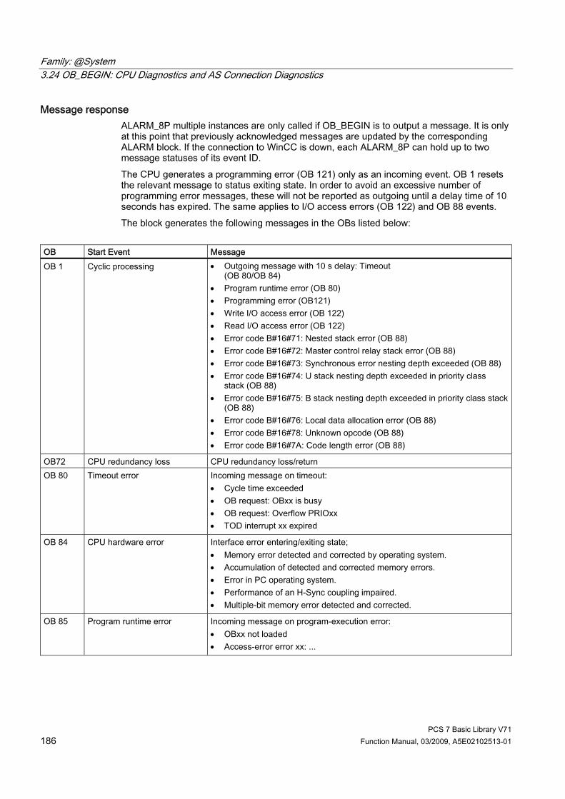
Family: @System 3.24 OB_BEGIN: CPU Diagnostics and AS Connection Diagnostics
PCS 7 Basic Library V71 186 Function Manual, 03/2009, A5E02102513-01
Message response ALARM_8P multiple instances are only called if OB_BEGIN is to output a message. It is only at this point that previously acknowledged messages are updated by the corresponding ALARM block. If the connection to WinCC is down, each ALARM_8P can hold up to two message statuses of its event ID. The CPU generates a programming error (OB 121) only as an incoming event. OB 1 resets the relevant message to status exiting state. In order to avoid an excessive number of programming error messages, these will not be reported as outgoing until a delay time of 10 seconds has expired. The same applies to I/O access errors (OB 122) and OB 88 events. The block generates the following messages in the OBs listed below:
OB Start Event Message OB 1 Cyclic processing • Outgoing message with 10 s delay: Timeout
(OB 80/OB 84) • Program runtime error (OB 80) • Programming error (OB121) • Write I/O access error (OB 122) • Read I/O access error (OB 122) • Error code B#16#71: Nested stack error (OB 88) • Error code B#16#72: Master control relay stack error (OB 88) • Error code B#16#73: Synchronous error nesting depth exceeded (OB 88) • Error code B#16#74: U stack nesting depth exceeded in priority class
stack (OB 88) • Error code B#16#75: B stack nesting depth exceeded in priority class stack
(OB 88) • Error code B#16#76: Local data allocation error (OB 88) • Error code B#16#78: Unknown opcode (OB 88) • Error code B#16#7A: Code length error (OB 88)
OB72 CPU redundancy loss CPU redundancy loss/return OB 80 Timeout error Incoming message on timeout:
• Cycle time exceeded • OB request: OBxx is busy • OB request: Overflow PRIOxx • TOD interrupt xx expired
OB 84 CPU hardware error Interface error entering/exiting state; • Memory error detected and corrected by operating system. • Accumulation of detected and corrected memory errors. • Error in PC operating system. • Performance of an H-Sync coupling impaired. • Multiple-bit memory error detected and corrected.
OB 85 Program runtime error Incoming message on program-execution error: • OBxx not loaded • Access-error error xx: ...

Family: @System 3.24 OB_BEGIN: CPU Diagnostics and AS Connection Diagnostics
PCS 7 Basic Library V71 Function Manual, 03/2009, A5E02102513-01 187
OB Start Event Message OB 88 Stop avoidance Incoming message on OB 88 events:
• Error code B#16#71: Nested stack error • Error code B#16#72: Master control relay stack error • Error code B#16#73: Nesting depth exceeded on synchronization errors • Error code B#16#74: U-stack nesting depth exceeded in the priority class
stack • Error code B#16#75: B-stack nesting depth exceeded in the priority class
stack • Error code B#16#76: Local data allocation error • Error code B#16#78: Unknown opcode • Error code B#16#7A: Code length error
OB100 Restart Initialization of ALARM_8P OB121 Programming error Programming error incoming OB122 I/O access error • Read I/O access, incoming
• Write I/O access, entering state
Operating and monitoring Note: If you have selected the "Enable operator control and monitoring" option in the block object properties in the CFC, the variables transferred to the OS are identified under "I/Os of ..." (OCM column, "+"). Default: Option not activated. If asset management is used in the project and the diagnostic pictures have been generated, then the faceplate can be called via its block icon. ● Asset management block icons (Page 284) ● OB_BEGIN faceplate (Page 292) If no asset management is used in the project, the "OB-BEGIN" block icon is used to display avoidance of stop. See also: Display for avoiding stop without asset management (Page 281)
Additional information You will find more information in: Message texts and associated values of OB_BEGIN (Page 189) Maintenance status of MS (Page 326)
See also Faceplates: Asset Management (Page 286)
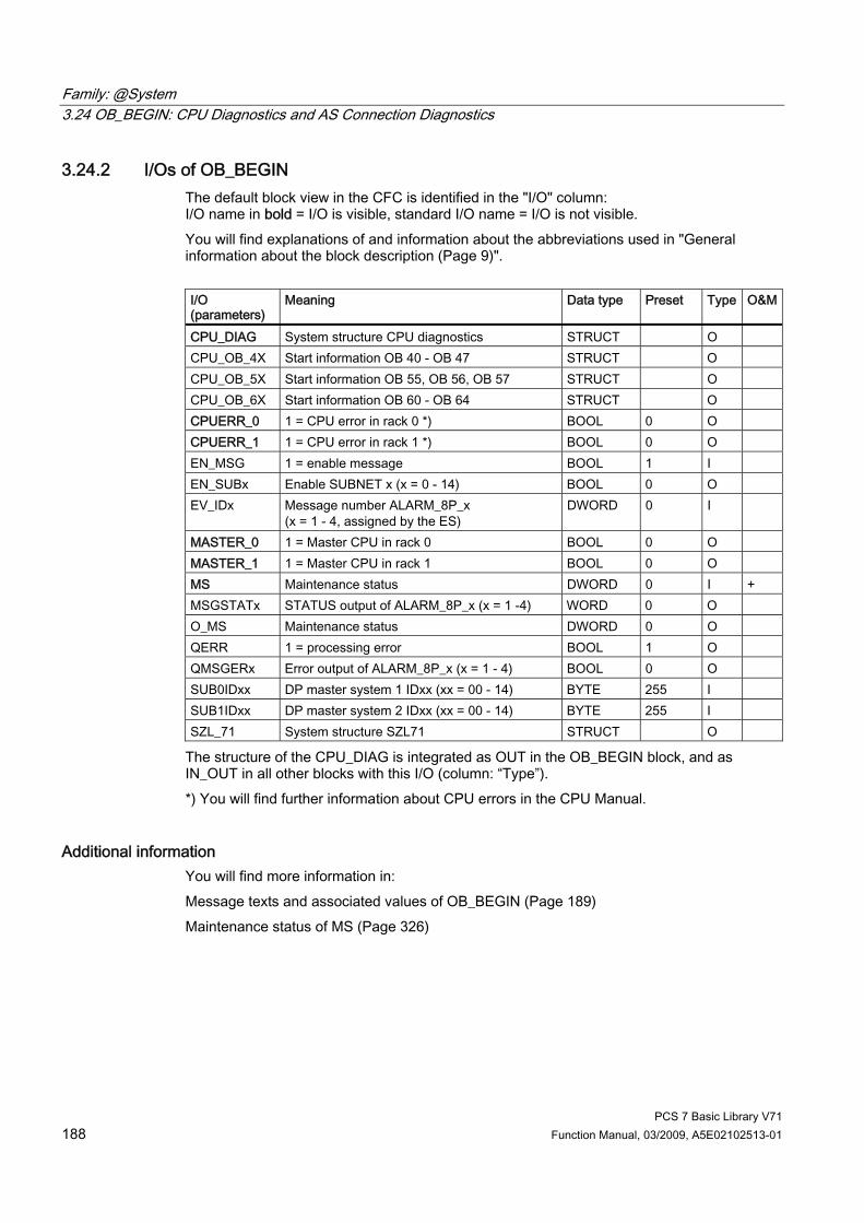
Family: @System 3.24 OB_BEGIN: CPU Diagnostics and AS Connection Diagnostics
PCS 7 Basic Library V71 188 Function Manual, 03/2009, A5E02102513-01
3.24.2 I/Os of OB_BEGIN The default block view in the CFC is identified in the "I/O" column: I/O name in bold = I/O is visible, standard I/O name = I/O is not visible. You will find explanations of and information about the abbreviations used in "General information about the block description (Page 9)". I/O (parameters)
Meaning Data type Preset Type O&M
CPU_DIAG System structure CPU diagnostics STRUCT O CPU_OB_4X Start information OB 40 - OB 47 STRUCT O CPU_OB_5X Start information OB 55, OB 56, OB 57 STRUCT O CPU_OB_6X Start information OB 60 - OB 64 STRUCT O CPUERR_0 1 = CPU error in rack 0 *) BOOL 0 O CPUERR_1 1 = CPU error in rack 1 *) BOOL 0 O EN_MSG 1 = enable message BOOL 1 I EN_SUBx Enable SUBNET x (x = 0 - 14) BOOL 0 O EV_IDx Message number ALARM_8P_x
(x = 1 - 4, assigned by the ES) DWORD 0 I
MASTER_0 1 = Master CPU in rack 0 BOOL 0 O MASTER_1 1 = Master CPU in rack 1 BOOL 0 O MS Maintenance status DWORD 0 I + MSGSTATx STATUS output of ALARM_8P_x (x = 1 -4) WORD 0 O O_MS Maintenance status DWORD 0 O QERR 1 = processing error BOOL 1 O QMSGERx Error output of ALARM_8P_x (x = 1 - 4) BOOL 0 O SUB0IDxx DP master system 1 IDxx (xx = 00 - 14) BYTE 255 I SUB1IDxx DP master system 2 IDxx (xx = 00 - 14) BYTE 255 I SZL_71 System structure SZL71 STRUCT O
The structure of the CPU_DIAG is integrated as OUT in the OB_BEGIN block, and as IN_OUT in all other blocks with this I/O (column: “Type”). *) You will find further information about CPU errors in the CPU Manual.
Additional information You will find more information in: Message texts and associated values of OB_BEGIN (Page 189) Maintenance status of MS (Page 326)
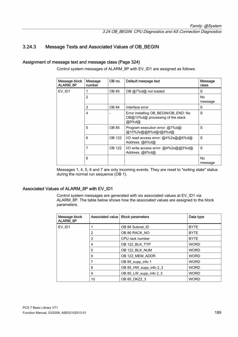
Family: @System 3.24 OB_BEGIN: CPU Diagnostics and AS Connection Diagnostics
PCS 7 Basic Library V71 Function Manual, 03/2009, A5E02102513-01 189
3.24.3 Message Texts and Associated Values of OB_BEGIN
Assignment of message text and message class (Page 324) Control system messages of ALARM_8P with EV_ID1 are assigned as follows: Message block ALARM_8P
Message number
OB no. Default message text Message class
1 OB 85 OB @7%d@ not loaded S 2 No
message 3 OB 84 Interface error S 4 - Error installing OB_BEGIN/OB_END: No
OB@10%d@ processing of the stack @9%d@
S
5 OB 85 Program execution error: @7%d@: @10%2s@@8%d@/@9%d@
S
6 OB 122 I/O read access error: @4%2s@@5%d@ Address: @6%d@
S
7 OB 122 I/O write access error: @4%2s@@5%d@ Address: @6%d@
S
EV_ID1
8 No message
Messages 1, 4, 5, 6 and 7 are only incoming events. They are reset to "exiting state" status during the normal run sequence (OB 1).
Associated Values of ALARM_8P with EV_ID1 Control system messages are generated with six associated values at EV_ID1 via ALARM_8P. The table below shows how the associated values are assigned to the block parameters. Message block ALARM_8P
Associated value Block parameters Data type
1 OB 86 Subnet_ID BYTE 2 OB 86 RACK_NO BYTE 3 CPU rack number BYTE 4 OB 122_BLK_TYP WORD 5 OB 122_BLK_NUM WORD 6 OB 122_MEM_ADDR WORD 7 OB 85_supp_info 1 WORD 8 OB 85_HW_supp_info 2_3 WORD 9 OB 85_LW_supp_info 2_3 WORD
EV_ID1
10 OB 85_DKZ2_3 WORD

Family: @System 3.24 OB_BEGIN: CPU Diagnostics and AS Connection Diagnostics
PCS 7 Basic Library V71 190 Function Manual, 03/2009, A5E02102513-01
Control system messages of ALARM_8P with EV_ID2 are assigned as follows: Message block ALARM_8P
Message number
OB no. Default message text Message class
1 OB 80 Net consumption of all OBs exceeds max. limit
M
2 OB 80 Emergency operation, cyclic OBs are used
S
3 OB 80 Priorities of the cyclic OBs not PCS 7 conform
M
4 No message 5 No message 6 No message 7 OB 121 Programming error @1%d@:
@2%2s@@5%d@ /@6%d@/@4%d@/@3%d@
S
EV_ID2
8 No message
Messages 1 to 3 are generated in CPU_RT (Page 25) and forwarded to OB_BEGIN. Message 7 is only an upcoming event. It is reset to "outgoing" status during the normal run sequence (OB 1). Message 7 is to be interpreted as follows, in accordance with the error code number before the colon: OB 121_BLK_TYP/OB 121_BLK_NUM/OB 121_PRG_ADDR/OB 121_FLT_REG/OB 121_RESERVED_1. This is described in the reference manual titled System Software for S7-300/400 System and Standard Functions. Example: 10.05.00 10:30:45 Programming error 35: FB44/1234/5/9

Family: @System 3.24 OB_BEGIN: CPU Diagnostics and AS Connection Diagnostics
PCS 7 Basic Library V71 Function Manual, 03/2009, A5E02102513-01 191
Associated Values of ALARM_8P with EV_ID2 Control system messages are generated with six associated values at EV_ID2 via ALARM_8P. The table below shows how the associated values are assigned to the block parameters. Message block ALARM_8P
Associated value
Block parameters Data type
1 OB 121_SW_FLT BYTE 2 OB 121_BLK_TYP WORD 3 OB 121_RESERVED_1 BYTE 4 OB 121_FLT_REG WORD 5 OB 121_BLK_NUM WORD 6 OB 121_PRG_ADDR WORD 7 OB 82 SUBNET_ID BYTE 8 OB 82 RACK_NO BYTE
EV_ID2
9 OB 82 SLOT_NO BYTE
Control system messages of ALARM_8P with EV_ID3 are assigned as follows: Message block ALARM_8P
Message number
OB no.
Default message text Message class
1 OB 80 Cycle time exceeded: @1%d@ms OB@2%d@ S 2 OB 80 OB request: OB3x still being processed F 3 OB 80 TOD interrupt OB @1%d@ expired (TOD jump) S 4 OB 80 TOD interrupt OB @1%d@ expired (Stop/Run) S 5 OB 80 OB request: Overflow PRIO @3%d S 6 OB 80 Clocked interrupt timeout: OB@2%d@ PRIO
@3%d@ S
7 OB 80 Interrupt lost: OB@2%d@ PRIO @3%d@ S
EV_ID3
8 OB 80 CiR synchronization time: @1%d@ ms S
Message 2 is generated in CPU_RT (Page 25) and forwarded to OB_BEGIN. Messages 1 to 8 are only incoming events. They are reset to "outgoing" status during the normal run sequence (OB 1).

Family: @System 3.24 OB_BEGIN: CPU Diagnostics and AS Connection Diagnostics
PCS 7 Basic Library V71 192 Function Manual, 03/2009, A5E02102513-01
Associated Values of ALARM_8P with EV_ID3 Control system messages are generated with seven associated values at EV_ID3 via ALARM_8P. The table below shows how the associated values are assigned to the block parameters. Message block ALARM_8P
Associated value
Block parameters Data type
1 OB 80_supp_info 1 WORD 2 OB 80_1st byte supp_info 2_3 BYTE
EV_ID3
3 OB 80_2nd byte supp_info 2_3 BYTE
Control system messages for ALARM_8P with EV_ID4 are assigned as follows: Message block ALARM_8P
Message number
Default message text Message class
1 OB 88(@6W%t#OB_BEGIN_TXT@): OB@1%d@ PRIO@2%d@ @3%2s@@4%d@ /@5%d@
S
2 OB_BEGIN: Diagnostics error RALRM STATUS = @7%8X@
S
3 No message 4 No message 5 No message 6 No message 7 No message
EV_ID_4
8 No message
Associated Values of ALARM_8P with EV_ID4 Message block ALARM_8P
Associated value
Meaning
1 Cause OB (M_OB 88.FLT_OB) 2 Priority class (M_OB 88.FLT_OB_PRIO) 3 Block type (M_OB 88.BLK_TYP) 4 Block number (M_OB 88.FLT_NUM) 5 MC7 command causing error
Relative address (M_OB 88.FLT_ADDR) 6 Error number in OB_BEGIN_TXT (M_OB 88.T_OB 88)
EV_ID4
7 Status RALRM
You will find the message texts and their text numbers in "Text library for OB_BEGIN (Page 344)".

Family: @System 3.24 OB_BEGIN: CPU Diagnostics and AS Connection Diagnostics
PCS 7 Basic Library V71 Function Manual, 03/2009, A5E02102513-01 193
3.24.4 Operator control and monitoring of OB_BEGIN
Additional information You can find additional information in the following sections: ● Asset management block icons (Page 284) ● OB_BEGIN faceplate (Page 292)
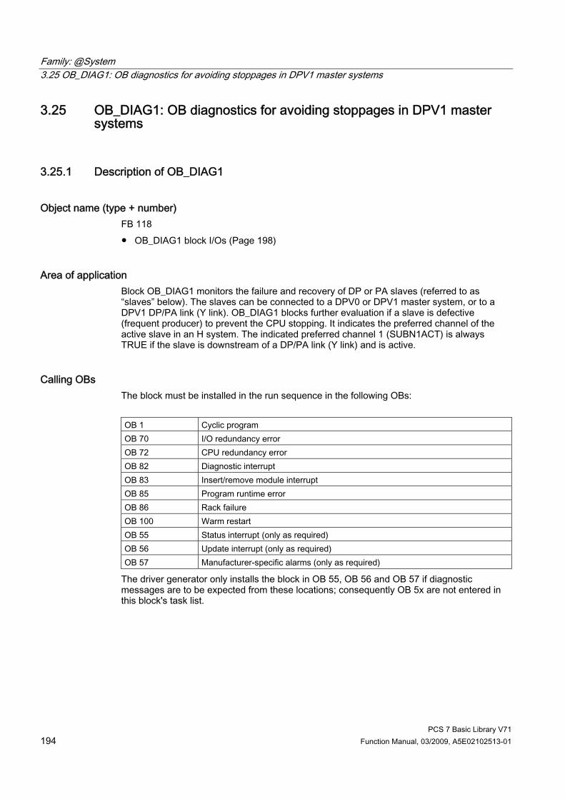
Family: @System 3.25 OB_DIAG1: OB diagnostics for avoiding stoppages in DPV1 master systems
PCS 7 Basic Library V71 194 Function Manual, 03/2009, A5E02102513-01
3.25 OB_DIAG1: OB diagnostics for avoiding stoppages in DPV1 master systems
3.25.1 Description of OB_DIAG1
Object name (type + number) FB 118 ● OB_DIAG1 block I/Os (Page 198)
Area of application Block OB_DIAG1 monitors the failure and recovery of DP or PA slaves (referred to as “slaves” below). The slaves can be connected to a DPV0 or DPV1 master system, or to a DPV1 DP/PA link (Y link). OB_DIAG1 blocks further evaluation if a slave is defective (frequent producer) to prevent the CPU stopping. It indicates the preferred channel of the active slave in an H system. The indicated preferred channel 1 (SUBN1ACT) is always TRUE if the slave is downstream of a DP/PA link (Y link) and is active.
Calling OBs The block must be installed in the run sequence in the following OBs: OB 1 Cyclic program OB 70 I/O redundancy error OB 72 CPU redundancy error OB 82 Diagnostic interrupt OB 83 Insert/remove module interrupt OB 85 Program runtime error OB 86 Rack failure OB 100 Warm restart OB 55 Status interrupt (only as required) OB 56 Update interrupt (only as required) OB 57 Manufacturer-specific alarms (only as required)
The driver generator only installs the block in OB 55, OB 56 and OB 57 if diagnostic messages are to be expected from these locations; consequently OB 5x are not entered in this block's task list.

Family: @System 3.25 OB_DIAG1: OB diagnostics for avoiding stoppages in DPV1 master systems
PCS 7 Basic Library V71 Function Manual, 03/2009, A5E02102513-01 195
Use in the CFC The following actions are executed automatically with the "Generate module drivers" CFC function: ● Block OB_DIAG1 is installed downstream of the SUBNET/DPAY_V1 block (when used
downstream of a DP/PA or Y link). ● The RACK_NO, LADDR, DADDR, EN_MSG_D, SUBN1_ID, SUBN2_ID, and SUBN_TYP
inputs are configured. ● The EN input is interconnected with the output of an AND block
whose inputs will be interconnected with output EN_SUBx (x = DP master system ID) of the OB_BEGIN block, and with output EN_Rxxx (xxx = rack/station number) of the SUBNET block.
● The CPU_DIAG OUT structure of the OB_BEGIN block and SUB_DIAG of the SUBNET block are interconnected with the IN_OUT structures of the same name of block OB_DIAG.
● RAC_DIAG_I is interconnected with its own RAC_DIAG OUT structure when used in a DP master system.
● RAC_DIAG_I is interconnected with the RAC_DIAG OUT structure of the DPAY_V1 block when used downstream of a Y link.
Function and method of operation The DPA_LINK block input receives information on the operational status of the slave, in other words whether it is in use on a DP master system (DPA_LINK = FALSE) or downstream of a DP/PA link (Y link). If the slave is connected to a DP master system, a failure is reported in OB 86. If the slave is connected downstream of a DP/PA link (Y link), the failure is reported in OB 83. The block counts the number of calls to an acyclic OB of a block instance before an OB 1 can be executed. OB_DIAG1 indicates higher-level errors of the CPU, DP master/slave (QRACKF, SUBN1ERR, SUBN2ERR). It determines the preferred channel of connected DP slaves (SUBN1ACT, SUBN2ACT). The group error message QRACKF indicates failure of the DP master or slave. An active DP slave has lost redundancy if one of the output parameters SUBN1ERR or SUBN2ERR = FALSE. Start and diagnostic information is read from the CPU_DIAG structure, which is interconnected with the CPU_DIAG structure of the OB_BEGIN block. The block evaluates error events, and uses the diagnostic address DADDR of the slave (on the DP master system only) to determine the currently active preferred channel (SUBN1ACT, SUBN2ACT) of redundant PROFIBUS DP interface circuits. The slaves downstream of a DP/PA link (Y link) are not always active. In this case, the diagnostic address DADDR is the diagnostic address of the link. The active preferred channel (SUBN1ACT, SUBN2ACT) is displayed here by the DP/PA link (Y link). The DP master systems or DP/PA links (Y link) must be operated in DPV1 mode (V1-MODE = TRUE). Failure and return of a DP slave are reported with ALARM_8P. The message function for all messages can be disabled with EN_MSG = FALSE. The “Device failure” message can be disabled with EM_MSG_D = FALSE (see “Message Response”).

Family: @System 3.25 OB_DIAG1: OB diagnostics for avoiding stoppages in DPV1 master systems
PCS 7 Basic Library V71 196 Function Manual, 03/2009, A5E02102513-01
Overload behavior Block OB_DIAG1 counts the frequency of the calls to the acyclic OB 55, OB 56, OB 57, OB 82, and OB 86 blocks (except in the case of a DP master system failure, see SUBNET block). If the block is downstream of a DP/PA or Y link, the calls will be counted in OB 83, rather than in OB 86. The following section deals only with OB 86. Each OB is assigned a counter that is checked for the condition > 5. If this condition is fulfilled, the block sets EN_F = FALSE (disable function block). The counters are reset in OB 1. The output EN_F = TRUE (enable function block) is set in all other OBs. OB_DIAG1 reports failure of the blocks mentioned above in OB 1, OB 82 or OB 86, including the geographic address of the slave. OB 55, OB 56, OB 57 and OB 82 are locked in the event of an overload, however, so the event is not evaluated in the downstream blocks. The outputs cannot correspond to the current slave status. If an OB is locked and no more slave events have been reported after a delay of around 1 minute, if it is OB 86 that is disabled, the slave status is checked, and the outputs are updated. It may take several cycles to update the slave status. If it is OB 82 that is disabled, rather than OB 86, the EN_DIAG variable is set to TRUE after around 1 minute. The interconnected DP slave block can then fetch the current diagnostic data for the slave, and update its own data. The same applies to OB 55, OB 56, and OB 57. The “outgoing” message about the fault is generated when the OB lock is canceled, and either a new event has occurred for this OB or the wait time has elapsed.
Redundancy The block supports redundant DP master systems in an H system (distributed I/Os only). The SUBN1_ID (connection to CPU 0) and SUBN2_ID (connection to CPU 1) inputs of the OB_DIAG1 block are configured with the numbers of the redundant DP master systems. If the DP master systems are not redundant, the remaining input is set to 16#FF (default).
Startup characteristics The availability of the slave is checked. In H systems the preferred channel of the slave is determined (active slaves only).
Error handling The block evaluates the error information from ALARM_8P, and writes it to the relevant output parameter. You will find additional information in the "Error information for output parameter MSG_STAT (Page 322)" section.

Family: @System 3.25 OB_DIAG1: OB diagnostics for avoiding stoppages in DPV1 master systems
PCS 7 Basic Library V71 Function Manual, 03/2009, A5E02102513-01 197
Message functionality The multiple instance ALARM_8P are only called if a message is to be output by this instance. It is only at this point that previously acknowledged messages are updated by the corresponding ALARM block. If the connection to WinCC is down, each ALARM_8P instance can hold up to two message statuses of its event ID (and generally no more than two messages). The block generates the messages listed below: OB no. Start Event Message 1 Cyclic processing Call of ALARM_8P due to incomplete transfer or
unacknowledged message 72 CPU redundancy loss If no redundant diagnostic repeater is connected to this CPU,
the "Slave" failure/return message is output. 70 Redundancy loss If there is no redundant slave connected to this DP master
system, message "Device" failure/return, otherwise message "Slave" redundancy loss/return
83 Removal/insertion Message "Slave" failure/return 86 Rack failure Message "Slave" failure/return 100 Restart Initialization of ALARM_8P
If the diagnostic blocks (e.g., MOD_PAL0) of a device also report the failure of a device, the "Device failure“ message can be disabled with EN_MSG_D = FALSE (this is done automatically by the driver generator).
Operator control and monitoring Note: If you selected the "Enable operator control and monitoring" option in the block object properties in the CFC, the variables transferred to the OS are identified under "I/Os of ..." (OCM column, "+"). Default: Option not activated. If asset management is used in the project and the diagnostic screens have been generated, the faceplate can be called via its block icon. ● Asset management block icons (Page 284) ● Asset management faceplates (Page 286)
Additional information For further information, refer to the following sections: Message texts and associated values of OB_DIAG1 (Page 200) Maintenance status of MS (Page 326)
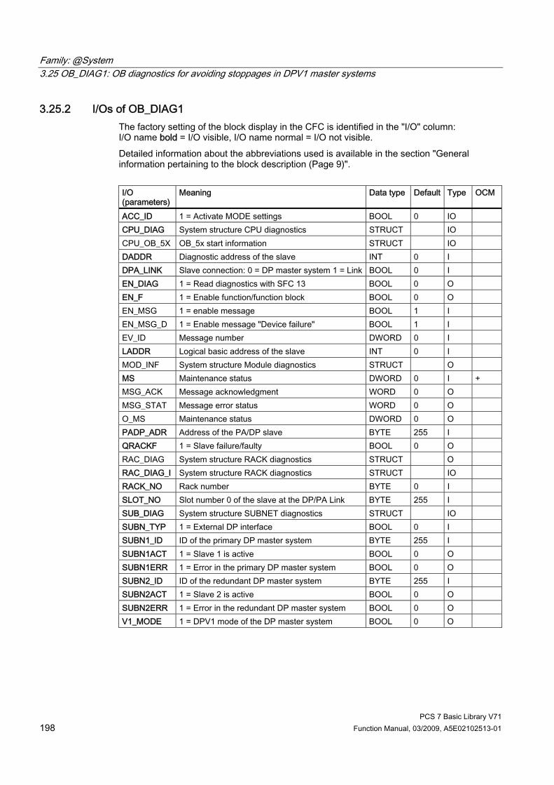
Family: @System 3.25 OB_DIAG1: OB diagnostics for avoiding stoppages in DPV1 master systems
PCS 7 Basic Library V71 198 Function Manual, 03/2009, A5E02102513-01
3.25.2 I/Os of OB_DIAG1 The factory setting of the block display in the CFC is identified in the "I/O" column: I/O name bold = I/O visible, I/O name normal = I/O not visible. Detailed information about the abbreviations used is available in the section "General information pertaining to the block description (Page 9)". I/O (parameters)
Meaning Data type Default Type OCM
ACC_ID 1 = Activate MODE settings BOOL 0 IO CPU_DIAG System structure CPU diagnostics STRUCT IO CPU_OB_5X OB_5x start information STRUCT IO DADDR Diagnostic address of the slave INT 0 I DPA_LINK Slave connection: 0 = DP master system 1 = Link BOOL 0 I EN_DIAG 1 = Read diagnostics with SFC 13 BOOL 0 O EN_F 1 = Enable function/function block BOOL 0 O EN_MSG 1 = enable message BOOL 1 I EN_MSG_D 1 = Enable message "Device failure" BOOL 1 I EV_ID Message number DWORD 0 I LADDR Logical basic address of the slave INT 0 I MOD_INF System structure Module diagnostics STRUCT O MS Maintenance status DWORD 0 I + MSG_ACK Message acknowledgment WORD 0 O MSG_STAT Message error status WORD 0 O O_MS Maintenance status DWORD 0 O PADP_ADR Address of the PA/DP slave BYTE 255 I QRACKF 1 = Slave failure/faulty BOOL 0 O RAC_DIAG System structure RACK diagnostics STRUCT O RAC_DIAG_I System structure RACK diagnostics STRUCT IO RACK_NO Rack number BYTE 0 I SLOT_NO Slot number 0 of the slave at the DP/PA Link BYTE 255 I SUB_DIAG System structure SUBNET diagnostics STRUCT IO SUBN_TYP 1 = External DP interface BOOL 0 I SUBN1_ID ID of the primary DP master system BYTE 255 I SUBN1ACT 1 = Slave 1 is active BOOL 0 O SUBN1ERR 1 = Error in the primary DP master system BOOL 0 O SUBN2_ID ID of the redundant DP master system BYTE 255 I SUBN2ACT 1 = Slave 2 is active BOOL 0 O SUBN2ERR 1 = Error in the redundant DP master system BOOL 0 O V1_MODE 1 = DPV1 mode of the DP master system BOOL 0 O

Family: @System 3.25 OB_DIAG1: OB diagnostics for avoiding stoppages in DPV1 master systems
PCS 7 Basic Library V71 Function Manual, 03/2009, A5E02102513-01 199
Additional information For further information, refer to the following sections: Message texts and associated values of OB_DIAG1 (Page 200) Maintenance status of MS (Page 326)

Family: @System 3.25 OB_DIAG1: OB diagnostics for avoiding stoppages in DPV1 master systems
PCS 7 Basic Library V71 200 Function Manual, 03/2009, A5E02102513-01
3.25.3 Message Texts and Associated Values of OB_DIAG1
Assignment of message text and message class (Page 324) Message No. Default message text Message
class 1 DP slave @1%d@/ @2%d@: Redundancy loss W 2 DP slave @1%d@/ @2%d@: Failure W 3 DP slave @1%d@/ @2%d@/@3%d@ : Repeated failure W 4 Device @1%d@/ @2%d@/@3%d@: recursive alarm (OB 82) W 5 Device @1%d@/ @2%d@/@3%d@: recursive alarm (OB 55) W 6 Device @1%d@/ @2%d@/@3%d@: recursive alarm (OB 56) W 7 Device @1%d@/ @2%d@/@3%d@: recursive alarm (OB 57) W 8 Device @1%d@/ @2%d@/@3%d@: Failure W
Assignment of Associated Values Associated value Block parameters 1 DP master system ID (SUBN_ID) 2 Rack/station number (RACK_NO) 3 Slot number (SLOT_NO)

Family: @System 3.26 OB_END: Reset stack pointer of OB_BEGIN
PCS 7 Basic Library V71 Function Manual, 03/2009, A5E02102513-01 201
3.26 OB_END: Reset stack pointer of OB_BEGIN
3.26.1 Description of OB_END
Object name (type + number) FC 280 ● OB_END block I/Os (Page 202)
Area of application The OB_END block is used to reset the stack pointer of OB_BEGIN.
Calling OBs The OB_END block is the final entry in the OB that contains an OB_BEGIN block. OB 1 Cyclic processing OB 55 Status interrupt (only as required) OB 56 Update interrupt (only as required) OB 57 Manufacturer-specific alarms (only as required) OB 70 I/O redundancy error OB 72 CPU redundancy error OB 80 Timeout error OB 81 Power supply error OB 82 Diagnostic interrupt OB 83 Remove/insert interrupt OB 84 CPU hardware error (only for CPU with this function) OB 85 Program runtime error OB 86 Rack failure OB 88 Stop avoidance OB 100 Restart OB 121 Programming error OB 122 I/O access error
Use in the CFC When the CFC function "Generate module drivers" is used, OB_END is automatically installed in the above OBs of the run sequence.
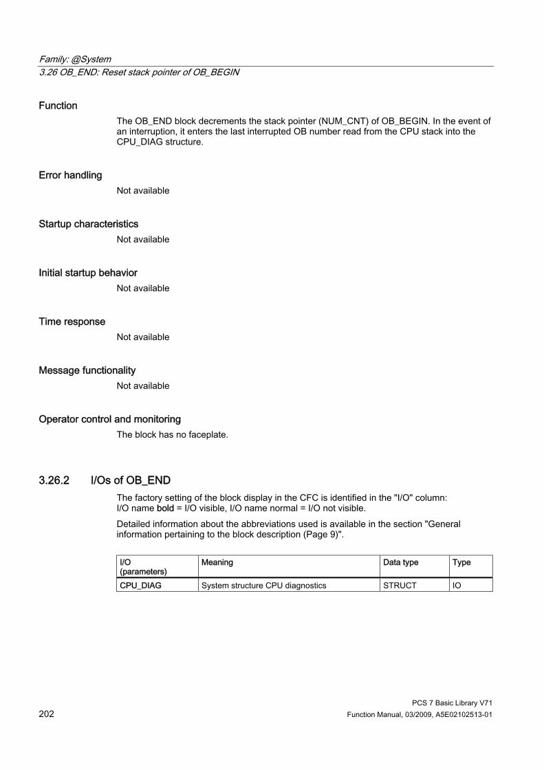
Family: @System 3.26 OB_END: Reset stack pointer of OB_BEGIN
PCS 7 Basic Library V71 202 Function Manual, 03/2009, A5E02102513-01
Function The OB_END block decrements the stack pointer (NUM_CNT) of OB_BEGIN. In the event of an interruption, it enters the last interrupted OB number read from the CPU stack into the CPU_DIAG structure.
Error handling Not available
Startup characteristics Not available
Initial startup behavior Not available
Time response Not available
Message functionality Not available
Operator control and monitoring The block has no faceplate.
3.26.2 I/Os of OB_END The factory setting of the block display in the CFC is identified in the "I/O" column: I/O name bold = I/O visible, I/O name normal = I/O not visible. Detailed information about the abbreviations used is available in the section "General information pertaining to the block description (Page 9)". I/O (parameters)
Meaning Data type Type
CPU_DIAG System structure CPU diagnostics STRUCT IO

Family: @System 3.27 OR_32_TS: OR value status of two redundant time-stamped signal modules, max. 32 channels
PCS 7 Basic Library V71 Function Manual, 03/2009, A5E02102513-01 203
3.27 OR_32_TS: OR value status of two redundant time-stamped signal modules, max. 32 channels
3.27.1 Description of OR_32_TS
Object name (type + number) FB 138 ● OR_32_TS block I/Os (Page 205)
Area of application The OR_32_TS block forms the resulting time stamp from two redundant time-stamped signal modules.
Calling OBs The block must be installed in OB 1.
Use in CFC The following actions are executed automatically with the "Generate module drivers" CFC function: ● The OR_32_TS block is installed in OB 1. ● The TS1_xx inputs are interconnected with the TS_xx output of IMDRV_TS that is
responsible for the signal module with the lower address. ● The TS2_xx inputs are interconnected with the TS_xx output of IMDRV_TS that is
responsible for the signal module with the higher address. ● The TS_xx outputs are interconnected with the inputs of the MSG_TS channel blocks or
Pcs7InIT.
Function and operating principle The OR_32_TS block forwards the time stamps of the channels of two redundant signal modules to the MSG_TS channel blocks or Pcs7InIT and acts like an OR function. ● If both channels are active, the time stamp of the signal module with the lower address is
always used. ● If one channel is passivated, the time stamp of the redundant channel is forwarded. ● If both channels are passivated, the time stamp of the signal module with the lower
address is entered.
Family: @System 3.27 OR_32_TS: OR value status of two redundant time-stamped signal modules, max. 32 channels
PCS 7 Basic Library V71 204 Function Manual, 03/2009, A5E02102513-01
Redundancy Redundancy of the modules in an H system is monitored in the higher-level RED_STATUS block.
Error handling The plausibility of input parameters is not checked.
Startup characteristics Not available
Message response Not available
Operating and monitoring Not available
Additional information You will find more information in Description of IMDRV_TS (Page 73)
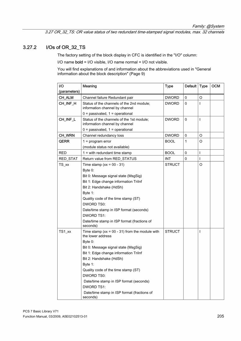
Family: @System 3.27 OR_32_TS: OR value status of two redundant time-stamped signal modules, max. 32 channels
PCS 7 Basic Library V71 Function Manual, 03/2009, A5E02102513-01 205
3.27.2 I/Os of OR_32_TS The factory setting of the block display in CFC is identified in the "I/O" column: I/O name bold = I/O visible, I/O name normal = I/O not visible. You will find explanations of and information about the abbreviations used in "General information about the block description" (Page 9) I/O (parameters)
Meaning Type Default Type OCM
CH_ALM Channel failure Redundant pair DWORD 0 O CH_INF_H Status of the channels of the 2nd module;
information channel by channel 0 = passivated, 1 = operational
DWORD 0 I
CH_INF_L Status of the channels of the 1st module; information channel by channel 0 = passivated, 1 = operational
DWORD 0 I
CH_WRN Channel redundancy loss DWORD 0 O QERR 1 = program error
(module status not available) BOOL 1 O
RED 1 = with redundant time stamp BOOL 0 I RED_STAT Return value from RED_STATUS INT 0 I TS_xx Time stamp (xx = 00 - 31)
Byte 0: Bit 0: Message signal state (MsgSig) Bit 1: Edge change information TriInf Bit 2: Handshake (HdSh) Byte 1: Quality code of the time stamp (ST) DWORD TS0: Date/time stamp in ISP format (seconds) DWORD TS1: Date/time stamp in ISP format (fractions of seconds)
STRUCT O
TS1_xx Time stamp (xx = 00 - 31) from the module with the lower address Byte 0: Bit 0: Message signal state (MsgSig) Bit 1: Edge change information TriInf Bit 2: Handshake (HdSh) Byte 1: Quality code of the time stamp (ST) DWORD TS0: Date/time stamp in ISP format (seconds) DWORD TS1: Date/time stamp in ISP format (fractions of seconds)
STRUCT I
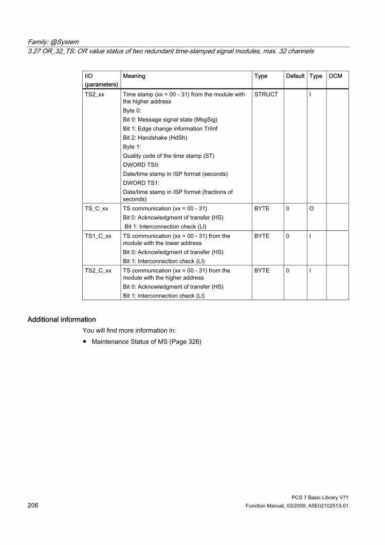
Family: @System 3.27 OR_32_TS: OR value status of two redundant time-stamped signal modules, max. 32 channels
PCS 7 Basic Library V71 206 Function Manual, 03/2009, A5E02102513-01
I/O (parameters)
Meaning Type Default Type OCM
TS2_xx Time stamp (xx = 00 - 31) from the module with the higher address Byte 0: Bit 0: Message signal state (MsgSig) Bit 1: Edge change information TriInf Bit 2: Handshake (HdSh) Byte 1: Quality code of the time stamp (ST) DWORD TS0: Date/time stamp in ISP format (seconds) DWORD TS1: Date/time stamp in ISP format (fractions of seconds)
STRUCT I
TS_C_xx TS communication (xx = 00 - 31) Bit 0: Acknowledgment of transfer (HS) Bit 1: Interconnection check (LI)
BYTE 0 O
TS1_C_xx TS communication (xx = 00 - 31) from the module with the lower address Bit 0: Acknowledgment of transfer (HS) Bit 1: Interconnection check (LI)
BYTE 0 I
TS2_C_xx TS communication (xx = 00 - 31) from the module with the higher address Bit 0: Acknowledgment of transfer (HS) Bit 1: Interconnection check (LI)
BYTE 0 I
Additional information You will find more information in: ● Maintenance Status of MS (Page 326)

Family: @System 3.28 OR_HA16C: OR value status of 2 redundant HART modules, max. 16 channels, module granular
PCS 7 Basic Library V71 Function Manual, 03/2009, A5E02102513-01 207
3.28 OR_HA16C: OR value status of 2 redundant HART modules, max. 16 channels, module granular
3.28.1 Description of OR_HA16C
Object name (type + number) FB 133 ● OR_HA16C block I/Os (Page 210)
Area of application The OR_HA16C block is used to create a value status from two redundant signal modules, and reports loss of redundancy for HART modules.
Calling OBs The block must be installed in OB 100 and in the OB before the MOD_HA driver block that is responsible for the relevant module.
Use in CFC The following actions are executed automatically with the "Generate module drivers" CFC function: ● The OR_HA16C block is installed before its interconnected MOD_HA driver block in its
OB. ● MODE1_xx inputs are interconnected with the OMODE_xx outputs of the MOD_x block in
the primary module. ● MODE2_xx inputs are interconnected with the OMODE_xx outputs of the MOD_x block in
the redundant module. ● The MOD_INF1 input structure is interconnected with the MOD_INF output structure of
the MOD_x block in the primary module. ● The MOD_INF2 input structure is interconnected with the MOD_INF output structure of
the MOD_x block in the redundant module. ● The ACTIV_H and ACTIV_L inputs are interconnected with the outputs of the same name
of the RED_STATUS block in the redundant module. ● The OMODE_xx outputs are interconnected with the downstream MOD_HA. ● The OUT structure CPU_DIAG of the OB_BEGIN block is interconnected with the
IN_OUT structures of the same name of the OR_HA_16C block. ● The inputs RACKF1 and RACKF2 are interconnected with the outputs QRACKF1 and
QRACKF2 of MOD_x. ● The inputs CH_INF_H and CH_INF_L are interconnected with the same name outputs of
RED_STATUS.
Family: @System 3.28 OR_HA16C: OR value status of 2 redundant HART modules, max. 16 channels, module granular
PCS 7 Basic Library V71 208 Function Manual, 03/2009, A5E02102513-01
● The output parameter of DXCHG_xx is interconnected with the following channel block at the DataXchg parameter.
● The output parameter of O_MS is interconnected with the following channel block at the MS parameter.
Function and operating principle The value status of a signal module and of a redundant signal module are ORed by the OR_HA16C block. Signal modules or signal channels set to passive mode by the system are regarded as invalid. The "At least one channel pair does not match", "Redundancy loss" and "Failure of the redundant I/O" events are reported by ALARM_8P. The message function can be disabled. When module signals are processed in different OB 3x, in very few cases, a faulty signal value may be processed in one cycle by one of the channel blocks configured to process the module signals following a process-control malfunction affecting the module. This can be avoided by processing all channel blocks of a module in the OB3x that also processes the process image partition to which this module is assigned. For a passivated block or passivated channel when setting the DEPASS input the depassivation can be triggered. For this the function RED_DEPA (FC 451) is called internally. For OR_M_xxC / OR_HA16C blocks: For channel-granular redundancy, in the event of one channel failing, "Loss of Redundancy Channel x" is reported. If both channels fail, "Redundancy pair failure channel x" is reported. With OR_HA16C, the message "Redundancy pair failure HART variable 01" to "Redundancy pair failure HART variable 08" is output for HART signals 01 to 08. The message function can be disabled.
For all OR blocks Depassivation can be triggered for a passivated block or channel by setting the DEPASS input. For this, the RED_DEPA function (FC 451) is called internally.
Redundancy Redundancy of the modules is monitored in a higher-level RED_STATUS block (FB 453).
Error handling The plausibility of input parameters is not checked.
Startup characteristics The OMODE_xx outputs are updated when the "Startup" bit is set. ALARM_8P will be initialized.
Time response Not available

Family: @System 3.28 OR_HA16C: OR value status of 2 redundant HART modules, max. 16 channels, module granular
PCS 7 Basic Library V71 Function Manual, 03/2009, A5E02102513-01 209
Message response OR_HA16C uses ALARM_8P for reporting. The message function can be disabled by setting EN_MSG = FALSE.
Operating and monitoring Note: If you have selected the "Enable operator control and monitoring" option in the block object properties in the CFC, the variables transferred to the OS are identified under "I/Os of ..." (OCM column, "+"). Default: Option not activated. If asset management is used in the project and the diagnostic pictures have been generated, then the faceplate can be called via its block icon. ● Asset management block icons (Page 284) ● Asset management faceplates (Page 286) Note: Online help and the manual "PCS 7 FACEPLATES" are only available if the "PCS 7 FACEPLATES" software package is installed.
Additional information You will find more information in: Message texts and associated values of OR_HA16C (Page 212) Maintenance status of MS (Page 326) You will find more information on this in PCS 7 Advanced Process Library > Basics of APL > General functions of the blocks > Operating, monitoring and reporting > Maintenance release

Family: @System 3.28 OR_HA16C: OR value status of 2 redundant HART modules, max. 16 channels, module granular
PCS 7 Basic Library V71 210 Function Manual, 03/2009, A5E02102513-01
3.28.2 I/Os of OR_M_8C / OR_M_16C / OR_M_32C / OR_HA16C The OR_M_8C and OR_M_16C / OR_HA16C / OR_M_32C block I/Os are identical, with the exception of the number of MODE1_xx and MODE2_xx and OMODE_xx. The factory setting of the block display in CFC is identified in the "I/O" column: I/O namebold = I/O visible, I/O name normal = I/O not visible. You will find explanations of and information about the abbreviations used in "General information about the block description (Page 9)".
I/O (parameters)
Meaning Data type Default Type OCM
ACTIV_H 1 = module with more significant address is active BOOL 0 I ACTIV_L 1 = module with less significant address is active BOOL 0 I CHAN_NUM Number of channels -1 INT 7 (OR_M_8C)
15 (OR_M_16C) 31 (OR_M_32C) 15 (OR_HA16C)
I
CH_ALM Channel failure Redundant pair DWORD 0 O CH_EXIST Channel exists DWORD 0 O + CH_INF_H Status of the channels on the 2nd module; info on a
channel basis 0 = passivated, 1 = in service
DWORD 0 I
CH_INF_L Status of the channels on the 1st module; info on a channel basis 0 = passivated, 1 = in service
DWORD 0 I
CH_OK Channel OK DWORD 0 O + CH_WRN Channel redundancy loss DWORD 0 O CPU_DIAG System structure: CPU diagnostics STRUCT IO DEPASS 1 = depassivation BOOL 0 I + DEPASS_EN 1 = enable depassivation BOOL 1 I DXCHG_xx Bidirectional data exchange channel (xx = 00 - 31)
Bit 0 = Release for maintenance Bits 1-31 = Reserve
DWORD 0 O
EN_MSG 1 = enable message BOOL 1 I EV_IDx Message number (x = 1 – 3 / 1 – 5 / 1 - 9 / 1 - 5) DWORD 0 I EXT_INFO Supplemental info of RED_OUT INT 0 O EXT_STAT Release for maintenance - extended status DWORD 0 O + MOD_INF1 Module parameters module 1 STRUCT IO MOD_INF2 Module parameters module 2 STRUCT IO MOD_STAT Module status word from RED_STATUS WORD 0 I MODE1_xx Channel mode (xx = 00 – 07 / 00 – 15 / 00 - 31) on the
primary module HART variable mode x (x = 1 - 8) on the primary module
DWORD 0 I
MODE2_xx Channel mode (xx = 00 – 07 / 00 – 15 / 00 - 31) on the redundant module HART variable mode x (x = 1 - 8) on the redundant module
DWORD 0 I

Family: @System 3.28 OR_HA16C: OR value status of 2 redundant HART modules, max. 16 channels, module granular
PCS 7 Basic Library V71 Function Manual, 03/2009, A5E02102513-01 211
I/O (parameters)
Meaning Data type Default Type OCM
MS Maintenance status DWORD 0 I + MSG_ACKx Message acknowledgement ALARM_8P_x
(x = 1 – 3 / 1 – 5 / 1 - 9 / 1 - 5) WORD 0 O
MSG_STATx Message error information ALARM_8P_x (x = 1 – 3 / 1 – 5 / 1 - 9 / 1 - 5)
WORD 0 O
O_MS Maintenance status DWORD 0 O OMODE_xx Channel mode (xx = 00 – 07 / 00 – 15 / 00 - 31)
mode HART variable x (x = 1 - 8) DWORD 0 O
QDISCREP 1 = At least one channel pair does not match BOOL 0 O QERR 1 = program runtime error
(cannot determine module status) BOOL 1 O
QMODF1 1 = error module 1 BOOL 0 O QMODF2 1 = error module 2 BOOL 0 O QPASS 1 = at least one module is passivated BOOL 0 O + RACKF1 1 = error rack 1 BOOL 0 I RACKF2 1 = error rack 2 BOOL 0 I RED_STAT Value returned by the RED_STATUS block INT 0 I RETURN_VAL Error information from RED_OUT INT 0 O
Additional information For further information, refer to the following sections: Maintenance status of MS (Page 326) Message texts and associated values of OR_M_8C (Page 232) Message texts and associated values of OR_M_16C (Page 218) Message texts and associated values of OR_HA16C (Page 212) Message texts and associated values of OR_M_32C (Page 223) General information about the block description (Page 9)
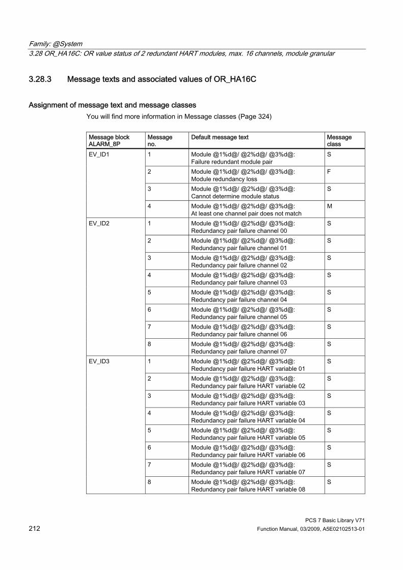
Family: @System 3.28 OR_HA16C: OR value status of 2 redundant HART modules, max. 16 channels, module granular
PCS 7 Basic Library V71 212 Function Manual, 03/2009, A5E02102513-01
3.28.3 Message texts and associated values of OR_HA16C
Assignment of message text and message classes You will find more information in Message classes (Page 324) Message block ALARM_8P
Message no.
Default message text Message class
1 Module @1%d@/ @2%d@/ @3%d@: Failure redundant module pair
S
2 Module @1%d@/ @2%d@/ @3%d@: Module redundancy loss
F
3 Module @1%d@/ @2%d@/ @3%d@: Cannot determine module status
S
EV_ID1
4 Module @1%d@/ @2%d@/ @3%d@: At least one channel pair does not match
M
1 Module @1%d@/ @2%d@/ @3%d@: Redundancy pair failure channel 00
S
2 Module @1%d@/ @2%d@/ @3%d@: Redundancy pair failure channel 01
S
3 Module @1%d@/ @2%d@/ @3%d@: Redundancy pair failure channel 02
S
4 Module @1%d@/ @2%d@/ @3%d@: Redundancy pair failure channel 03
S
5 Module @1%d@/ @2%d@/ @3%d@: Redundancy pair failure channel 04
S
6 Module @1%d@/ @2%d@/ @3%d@: Redundancy pair failure channel 05
S
7 Module @1%d@/ @2%d@/ @3%d@: Redundancy pair failure channel 06
S
EV_ID2
8 Module @1%d@/ @2%d@/ @3%d@: Redundancy pair failure channel 07
S
1 Module @1%d@/ @2%d@/ @3%d@: Redundancy pair failure HART variable 01
S
2 Module @1%d@/ @2%d@/ @3%d@: Redundancy pair failure HART variable 02
S
3 Module @1%d@/ @2%d@/ @3%d@: Redundancy pair failure HART variable 03
S
4 Module @1%d@/ @2%d@/ @3%d@: Redundancy pair failure HART variable 04
S
5 Module @1%d@/ @2%d@/ @3%d@: Redundancy pair failure HART variable 05
S
6 Module @1%d@/ @2%d@/ @3%d@: Redundancy pair failure HART variable 06
S
7 Module @1%d@/ @2%d@/ @3%d@: Redundancy pair failure HART variable 07
S
EV_ID3
8 Module @1%d@/ @2%d@/ @3%d@: Redundancy pair failure HART variable 08
S
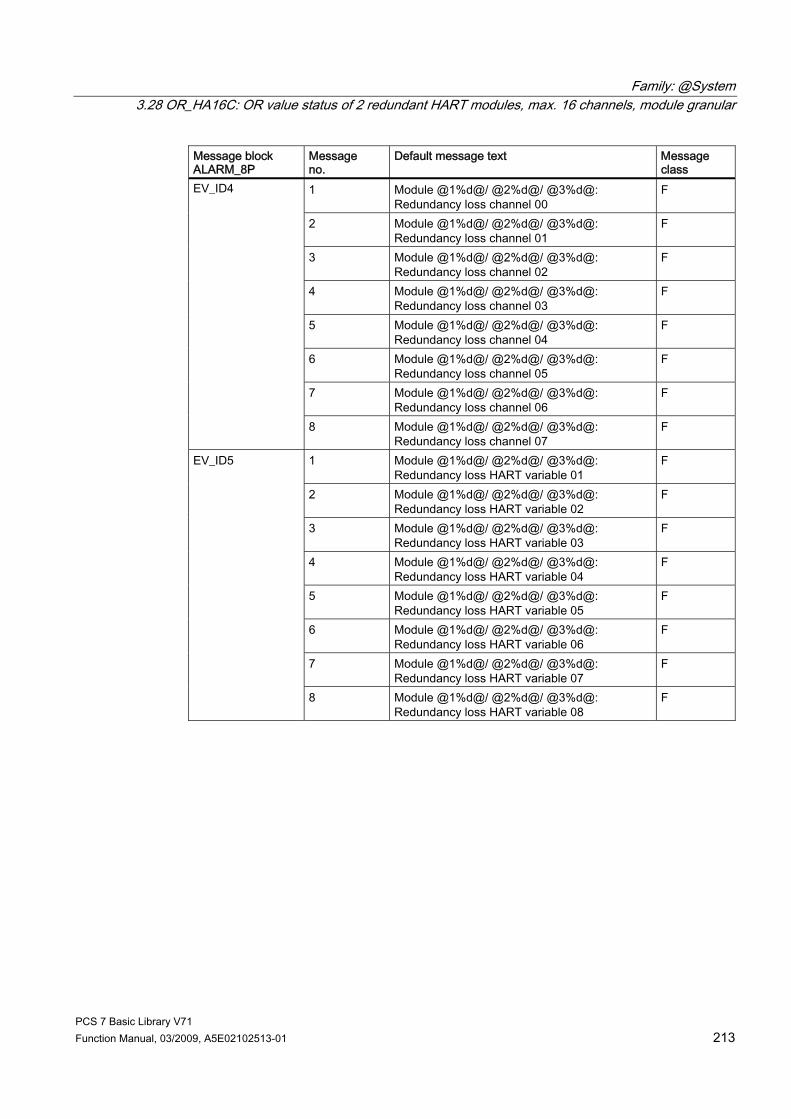
Family: @System 3.28 OR_HA16C: OR value status of 2 redundant HART modules, max. 16 channels, module granular
PCS 7 Basic Library V71 Function Manual, 03/2009, A5E02102513-01 213
Message block ALARM_8P
Message no.
Default message text Message class
1 Module @1%d@/ @2%d@/ @3%d@: Redundancy loss channel 00
F
2 Module @1%d@/ @2%d@/ @3%d@: Redundancy loss channel 01
F
3 Module @1%d@/ @2%d@/ @3%d@: Redundancy loss channel 02
F
4 Module @1%d@/ @2%d@/ @3%d@: Redundancy loss channel 03
F
5 Module @1%d@/ @2%d@/ @3%d@: Redundancy loss channel 04
F
6 Module @1%d@/ @2%d@/ @3%d@: Redundancy loss channel 05
F
7 Module @1%d@/ @2%d@/ @3%d@: Redundancy loss channel 06
F
EV_ID4
8 Module @1%d@/ @2%d@/ @3%d@: Redundancy loss channel 07
F
1 Module @1%d@/ @2%d@/ @3%d@: Redundancy loss HART variable 01
F
2 Module @1%d@/ @2%d@/ @3%d@: Redundancy loss HART variable 02
F
3 Module @1%d@/ @2%d@/ @3%d@: Redundancy loss HART variable 03
F
4 Module @1%d@/ @2%d@/ @3%d@: Redundancy loss HART variable 04
F
5 Module @1%d@/ @2%d@/ @3%d@: Redundancy loss HART variable 05
F
6 Module @1%d@/ @2%d@/ @3%d@: Redundancy loss HART variable 06
F
7 Module @1%d@/ @2%d@/ @3%d@: Redundancy loss HART variable 07
F
EV_ID5
8 Module @1%d@/ @2%d@/ @3%d@: Redundancy loss HART variable 08
F
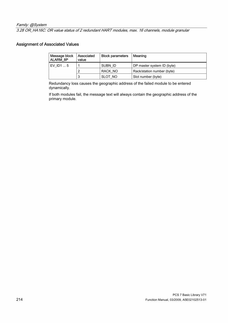
Family: @System 3.28 OR_HA16C: OR value status of 2 redundant HART modules, max. 16 channels, module granular
PCS 7 Basic Library V71 214 Function Manual, 03/2009, A5E02102513-01
Assignment of Associated Values Message block ALARM_8P
Associated value
Block parameters Meaning
1 SUBN_ID DP master system ID (byte) 2 RACK_NO Rack/station number (byte)
EV_ID1 ... 5
3 SLOT_NO Slot number (byte)
Redundancy loss causes the geographic address of the failed module to be entered dynamically. If both modules fail, the message text will always contain the geographic address of the primary module.
Family: @System 3.29 OR_M_16C: OR value status of 2 redundant signal modules, max. 16 channels, channel granular
PCS 7 Basic Library V71 Function Manual, 03/2009, A5E02102513-01 215
3.29 OR_M_16C: OR value status of 2 redundant signal modules, max. 16 channels, channel granular
3.29.1 Description of OR_M_16
Object name (type + number) FB 84 ● OR_M_16C block I/Os (Page 216) The OR_M_16C block corresponds to OR_M_8C (Page 227), but with 16, rather than 8 channels.
Additional information For further information, refer to the following sections: Message texts and associated values of OR_M_16C (Page 218) Maintenance status of MS (Page 326) You will find more information on this in PCS 7 Advanced Process Library > Basics of APL > General functions of the blocks > Operating, monitoring and reporting > Maintenance release

Family: @System 3.29 OR_M_16C: OR value status of 2 redundant signal modules, max. 16 channels, channel granular
PCS 7 Basic Library V71 216 Function Manual, 03/2009, A5E02102513-01
3.29.2 I/Os of OR_M_8C / OR_M_16C / OR_M_32C / OR_HA16C The OR_M_8C and OR_M_16C / OR_HA16C / OR_M_32C block I/Os are identical, with the exception of the number of MODE1_xx and MODE2_xx and OMODE_xx. The factory setting of the block display in CFC is identified in the "I/O" column: I/O namebold = I/O visible, I/O name normal = I/O not visible. You will find explanations of and information about the abbreviations used in "General information about the block description (Page 9)".
I/O (parameters)
Meaning Data type Default Type OCM
ACTIV_H 1 = module with more significant address is active BOOL 0 I ACTIV_L 1 = module with less significant address is active BOOL 0 I CHAN_NUM Number of channels -1 INT 7 (OR_M_8C)
15 (OR_M_16C) 31 (OR_M_32C) 15 (OR_HA16C)
I
CH_ALM Channel failure Redundant pair DWORD 0 O CH_EXIST Channel exists DWORD 0 O + CH_INF_H Status of the channels on the 2nd module; info on a
channel basis 0 = passivated, 1 = in service
DWORD 0 I
CH_INF_L Status of the channels on the 1st module; info on a channel basis 0 = passivated, 1 = in service
DWORD 0 I
CH_OK Channel OK DWORD 0 O + CH_WRN Channel redundancy loss DWORD 0 O CPU_DIAG System structure: CPU diagnostics STRUCT IO DEPASS 1 = depassivation BOOL 0 I + DEPASS_EN 1 = enable depassivation BOOL 1 I DXCHG_xx Bidirectional data exchange channel (xx = 00 - 31)
Bit 0 = Release for maintenance Bits 1-31 = Reserve
DWORD 0 O
EN_MSG 1 = enable message BOOL 1 I EV_IDx Message number (x = 1 – 3 / 1 – 5 / 1 - 9 / 1 - 5) DWORD 0 I EXT_INFO Supplemental info of RED_OUT INT 0 O EXT_STAT Release for maintenance - extended status DWORD 0 O + MOD_INF1 Module parameters module 1 STRUCT IO MOD_INF2 Module parameters module 2 STRUCT IO MOD_STAT Module status word from RED_STATUS WORD 0 I MODE1_xx Channel mode (xx = 00 – 07 / 00 – 15 / 00 - 31) on the
primary module HART variable mode x (x = 1 - 8) on the primary module
DWORD 0 I
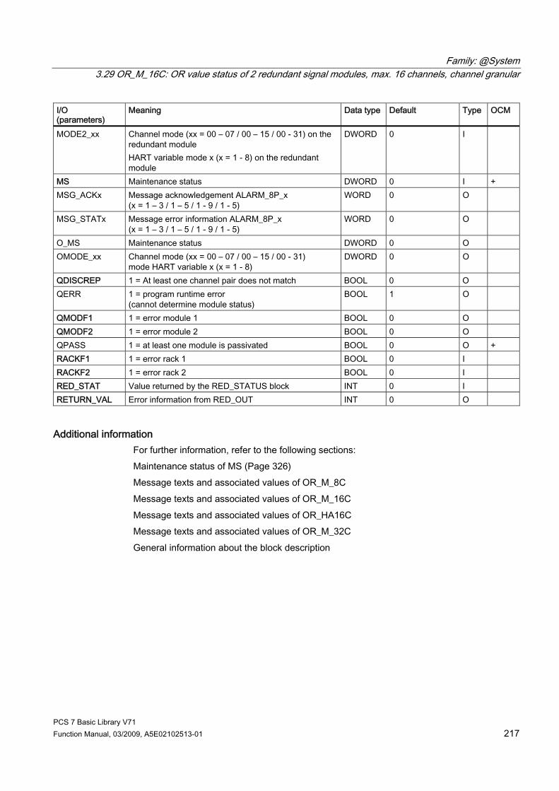
Family: @System 3.29 OR_M_16C: OR value status of 2 redundant signal modules, max. 16 channels, channel granular
PCS 7 Basic Library V71 Function Manual, 03/2009, A5E02102513-01 217
I/O (parameters)
Meaning Data type Default Type OCM
MODE2_xx Channel mode (xx = 00 – 07 / 00 – 15 / 00 - 31) on the redundant module HART variable mode x (x = 1 - 8) on the redundant module
DWORD 0 I
MS Maintenance status DWORD 0 I + MSG_ACKx Message acknowledgement ALARM_8P_x
(x = 1 – 3 / 1 – 5 / 1 - 9 / 1 - 5) WORD 0 O
MSG_STATx Message error information ALARM_8P_x (x = 1 – 3 / 1 – 5 / 1 - 9 / 1 - 5)
WORD 0 O
O_MS Maintenance status DWORD 0 O OMODE_xx Channel mode (xx = 00 – 07 / 00 – 15 / 00 - 31)
mode HART variable x (x = 1 - 8) DWORD 0 O
QDISCREP 1 = At least one channel pair does not match BOOL 0 O QERR 1 = program runtime error
(cannot determine module status) BOOL 1 O
QMODF1 1 = error module 1 BOOL 0 O QMODF2 1 = error module 2 BOOL 0 O QPASS 1 = at least one module is passivated BOOL 0 O + RACKF1 1 = error rack 1 BOOL 0 I RACKF2 1 = error rack 2 BOOL 0 I RED_STAT Value returned by the RED_STATUS block INT 0 I RETURN_VAL Error information from RED_OUT INT 0 O
Additional information For further information, refer to the following sections: Maintenance status of MS (Page 326) Message texts and associated values of OR_M_8C Message texts and associated values of OR_M_16C Message texts and associated values of OR_HA16C Message texts and associated values of OR_M_32C General information about the block description
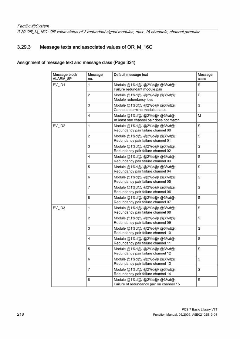
Family: @System 3.29 OR_M_16C: OR value status of 2 redundant signal modules, max. 16 channels, channel granular
PCS 7 Basic Library V71 218 Function Manual, 03/2009, A5E02102513-01
3.29.3 Message texts and associated values of OR_M_16C
Assignment of message text and message class (Page 324) Message block ALARM_8P
Message no.
Default message text Message class
1 Module @1%d@/ @2%d@/ @3%d@: Failure redundant module pair
S
2 Module @1%d@/ @2%d@/ @3%d@: Module redundancy loss
F
3 Module @1%d@/ @2%d@/ @3%d@: Cannot determine module status
S
EV_ID1
4 Module @1%d@/ @2%d@/ @3%d@: At least one channel pair does not match
M
1 Module @1%d@/ @2%d@/ @3%d@: Redundancy pair failure channel 00
S
2 Module @1%d@/ @2%d@/ @3%d@: Redundancy pair failure channel 01
S
3 Module @1%d@/ @2%d@/ @3%d@: Redundancy pair failure channel 02
S
4 Module @1%d@/ @2%d@/ @3%d@: Redundancy pair failure channel 03
S
5 Module @1%d@/ @2%d@/ @3%d@: Redundancy pair failure channel 04
S
6 Module @1%d@/ @2%d@/ @3%d@: Redundancy pair failure channel 05
S
7 Module @1%d@/ @2%d@/ @3%d@: Redundancy pair failure channel 06
S
EV_ID2
8 Module @1%d@/ @2%d@/ @3%d@: Redundancy pair failure channel 07
S
1 Module @1%d@/ @2%d@/ @3%d@: Redundancy pair failure channel 08
S
2 Module @1%d@/ @2%d@/ @3%d@: Redundancy pair failure channel 09
S
3 Module @1%d@/ @2%d@/ @3%d@: Redundancy pair failure channel 10
S
4 Module @1%d@/ @2%d@/ @3%d@: Redundancy pair failure channel 11
S
5 Module @1%d@/ @2%d@/ @3%d@: Redundancy pair failure channel 12
S
6 Module @1%d@/ @2%d@/ @3%d@: Redundancy pair failure channel 13
S
7 Module @1%d@/ @2%d@/ @3%d@: Redundancy pair failure channel 14
S
EV_ID3
8 Module @1%d@/ @2%d@/ @3%d@: Failure of redundancy pair on channel 15
S

Family: @System 3.29 OR_M_16C: OR value status of 2 redundant signal modules, max. 16 channels, channel granular
PCS 7 Basic Library V71 Function Manual, 03/2009, A5E02102513-01 219
Message block ALARM_8P
Message no.
Default message text Message class
1 Module @1%d@/ @2%d@/ @3%d@: Redundancy loss channel 00
F
2 Module @1%d@/ @2%d@/ @3%d@: Redundancy loss channel 01
F
3 Module @1%d@/ @2%d@/ @3%d@: Redundancy loss channel 02
F
4 Module @1%d@/ @2%d@/ @3%d@: Redundancy loss channel 03
F
5 Module @1%d@/ @2%d@/ @3%d@: Redundancy loss channel 04
F
6 Module @1%d@/ @2%d@/ @3%d@: Redundancy loss channel 05
F
7 Module @1%d@/ @2%d@/ @3%d@: Redundancy loss channel 06
F
8 Module @1%d@/ @2%d@/ @3%d@: Redundancy loss channel 07
F
1 Module @1%d@/ @2%d@/ @3%d@: Redundancy loss on channel 08
F
2 Module @1%d@/ @2%d@/ @3%d@: Redundancy loss channel 09
F
3 Module @1%d@/ @2%d@/ @3%d@: Redundancy loss channel 10
F
4 Module @1%d@/ @2%d@/ @3%d@: Redundancy loss channel 11
F
5 Module @1%d@/ @2%d@/ @3%d@: Redundancy loss channel 12
F
6 Module @1%d@/ @2%d@/ @3%d@: Redundancy loss channel 13
F
7 Module @1%d@/ @2%d@/ @3%d@: Redundancy loss channel 14
F
EV_ID4 EV_ID5
8 Module @1%d@/ @2%d@/ @3%d@: Redundancy loss on channel 15
F
Assignment of associated values Message block ALARM_8P
Associated value
Block parameters Meaning
1 SUBN_ID DP master system ID (byte) 2 RACK_NO Rack/station number (byte)
EV_ID1 ... 5
3 SLOT_NO Slot number (byte)
Redundancy loss causes the geographic address of the failed module to be entered dynamically. If both modules fail, the message text will always contain the geographic address of the primary module.

Family: @System 3.30 OR_M_32C: OR value status of 2 redundant signal modules, max. 32 channels, channel granular
PCS 7 Basic Library V71 220 Function Manual, 03/2009, A5E02102513-01
3.30 OR_M_32C: OR value status of 2 redundant signal modules, max. 32 channels, channel granular
3.30.1 Description of OR_M_32C
Object name (type + number) FB85 ● OR_M_32C block I/Os (Page 221) Block OR_M_32C corresponds to the OR_M_8C (Page 227) block, but with 32 channels instead of 8.
Additional information You will find more information in: Message texts and associated values of OR_M_32C (Page 223) Maintenance status of MS (Page 326) You will find more information on this in PCS 7 Advanced Process Library > Basics of APL > General functions of the blocks > Operating, monitoring and reporting > Maintenance release

Family: @System 3.30 OR_M_32C: OR value status of 2 redundant signal modules, max. 32 channels, channel granular
PCS 7 Basic Library V71 Function Manual, 03/2009, A5E02102513-01 221
3.30.2 I/Os of OR_M_8C / OR_M_16C / OR_M_32C / OR_HA16C The OR_M_8C and OR_M_16C / OR_HA16C / OR_M_32C block I/Os are identical, with the exception of the number of MODE1_xx and MODE2_xx and OMODE_xx. The factory setting of the block display in CFC is identified in the "I/O" column: I/O namebold = I/O visible, I/O name normal = I/O not visible. You will find explanations of and information about the abbreviations used in "General information about the block description (Page 9)".
I/O (parameters)
Meaning Data type Default Type OCM
ACTIV_H 1 = module with more significant address is active BOOL 0 I ACTIV_L 1 = module with less significant address is active BOOL 0 I CHAN_NUM Number of channels -1 INT 7 (OR_M_8C)
15 (OR_M_16C) 31 (OR_M_32C) 15 (OR_HA16C)
I
CH_ALM Channel failure Redundant pair DWORD 0 O CH_EXIST Channel exists DWORD 0 O + CH_INF_H Status of the channels on the 2nd module; info on a
channel basis 0 = passivated, 1 = in service
DWORD 0 I
CH_INF_L Status of the channels on the 1st module; info on a channel basis 0 = passivated, 1 = in service
DWORD 0 I
CH_OK Channel OK DWORD 0 O + CH_WRN Channel redundancy loss DWORD 0 O CPU_DIAG System structure: CPU diagnostics STRUCT IO DEPASS 1 = depassivation BOOL 0 I + DEPASS_EN 1 = enable depassivation BOOL 1 I DXCHG_xx Bidirectional data exchange channel (xx = 00 - 31)
Bit 0 = Release for maintenance Bits 1-31 = Reserve
DWORD 0 O
EN_MSG 1 = enable message BOOL 1 I EV_IDx Message number (x = 1 – 3 / 1 – 5 / 1 - 9 / 1 - 5) DWORD 0 I EXT_INFO Supplemental info of RED_OUT INT 0 O EXT_STAT Release for maintenance - extended status DWORD 0 O + MOD_INF1 Module parameters module 1 STRUCT IO MOD_INF2 Module parameters module 2 STRUCT IO MOD_STAT Module status word from RED_STATUS WORD 0 I MODE1_xx Channel mode (xx = 00 – 07 / 00 – 15 / 00 - 31) on the
primary module HART variable mode x (x = 1 - 8) on the primary module
DWORD 0 I
MODE2_xx Channel mode (xx = 00 – 07 / 00 – 15 / 00 - 31) on the redundant module HART variable mode x (x = 1 - 8) on the redundant module
DWORD 0 I

Family: @System 3.30 OR_M_32C: OR value status of 2 redundant signal modules, max. 32 channels, channel granular
PCS 7 Basic Library V71 222 Function Manual, 03/2009, A5E02102513-01
I/O (parameters)
Meaning Data type Default Type OCM
MS Maintenance status DWORD 0 I + MSG_ACKx Message acknowledgement ALARM_8P_x
(x = 1 – 3 / 1 – 5 / 1 - 9 / 1 - 5) WORD 0 O
MSG_STATx Message error information ALARM_8P_x (x = 1 – 3 / 1 – 5 / 1 - 9 / 1 - 5)
WORD 0 O
O_MS Maintenance status DWORD 0 O OMODE_xx Channel mode (xx = 00 – 07 / 00 – 15 / 00 - 31)
mode HART variable x (x = 1 - 8) DWORD 0 O
QDISCREP 1 = At least one channel pair does not match BOOL 0 O QERR 1 = program runtime error
(cannot determine module status) BOOL 1 O
QMODF1 1 = error module 1 BOOL 0 O QMODF2 1 = error module 2 BOOL 0 O QPASS 1 = at least one module is passivated BOOL 0 O + RACKF1 1 = error rack 1 BOOL 0 I RACKF2 1 = error rack 2 BOOL 0 I RED_STAT Value returned by the RED_STATUS block INT 0 I RETURN_VAL Error information from RED_OUT INT 0 O
Additional information For further information, refer to the following sections: Maintenance status of MS (Page 326) Message texts and associated values of OR_M_8C Message texts and associated values of OR_M_16C Message texts and associated values of OR_HA16C Message texts and associated values of OR_M_32C General information about the block description

Family: @System 3.30 OR_M_32C: OR value status of 2 redundant signal modules, max. 32 channels, channel granular
PCS 7 Basic Library V71 Function Manual, 03/2009, A5E02102513-01 223
3.30.3 Message texts and associated values of OR_M_32C
Assignment of message text and message class (Page 324) Message block ALARM_8P
Message no.
Default message text Message class
1 Module @1%d@/ @2%d@/ @3%d@: Failure redundant module pair
S
2 Module @1%d@/ @2%d@/ @3%d@: Module redundancy loss
F
3 Module @1%d@/ @2%d@/ @3%d@: Cannot determine module status
S
EV_ID1
4 Module @1%d@/ @2%d@/ @3%d@: At least one channel pair does not match
M
1 Module @1%d@/ @2%d@/ @3%d@: Redundancy pair failure channel 00
S
2 Module @1%d@/ @2%d@/ @3%d@: Failure of redundancy pair on channel 01
S
3 Module @1%d@/ @2%d@/ @3%d@: Failure of redundancy pair on channel 02
S
4 Module @1%d@/ @2%d@/ @3%d@: Failure of redundancy pair on channel 03
S
5 Module @1%d@/ @2%d@/ @3%d@: Failure of redundancy pair on channel 04
S
6 Module @1%d@/ @2%d@/ @3%d@: Failure of redundancy pair on channel 05
S
7 Module @1%d@/ @2%d@/ @3%d@: Failure of redundancy pair on channel 06
S
EV_ID2
8 Module @1%d@/ @2%d@/ @3%d@: Failure of redundancy pair on channel 07
S
1 Module @1%d@/ @2%d@/ @3%d@: Failure of redundancy pair on channel 08
S
2 Module @1%d@/ @2%d@/ @3%d@: Failure of redundancy pair on channel 09
S
3 Module @1%d@/ @2%d@/ @3%d@: Failure of redundancy pair on channel 10
S
4 Module @1%d@/ @2%d@/ @3%d@: Failure of redundancy pair on channel 11
S
5 Module @1%d@/ @2%d@/ @3%d@: Failure of redundancy pair on channel 12
S
6 Module @1%d@/ @2%d@/ @3%d@: Failure of redundancy pair on channel 13
S
7 Module @1%d@/ @2%d@/ @3%d@: Failure of redundancy pair on channel 14
S
EV_ID3
8 Module @1%d@/ @2%d@/ @3%d@: Redundancy pair failure channel 15
S
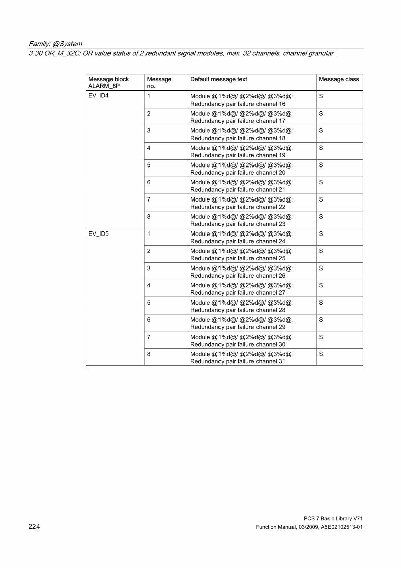
Family: @System 3.30 OR_M_32C: OR value status of 2 redundant signal modules, max. 32 channels, channel granular
PCS 7 Basic Library V71 224 Function Manual, 03/2009, A5E02102513-01
Message block ALARM_8P
Message no.
Default message text Message class
1 Module @1%d@/ @2%d@/ @3%d@: Redundancy pair failure channel 16
S
2 Module @1%d@/ @2%d@/ @3%d@: Redundancy pair failure channel 17
S
3 Module @1%d@/ @2%d@/ @3%d@: Redundancy pair failure channel 18
S
4 Module @1%d@/ @2%d@/ @3%d@: Redundancy pair failure channel 19
S
5 Module @1%d@/ @2%d@/ @3%d@: Redundancy pair failure channel 20
S
6 Module @1%d@/ @2%d@/ @3%d@: Redundancy pair failure channel 21
S
7 Module @1%d@/ @2%d@/ @3%d@: Redundancy pair failure channel 22
S
EV_ID4
8 Module @1%d@/ @2%d@/ @3%d@: Redundancy pair failure channel 23
S
1 Module @1%d@/ @2%d@/ @3%d@: Redundancy pair failure channel 24
S
2 Module @1%d@/ @2%d@/ @3%d@: Redundancy pair failure channel 25
S
3 Module @1%d@/ @2%d@/ @3%d@: Redundancy pair failure channel 26
S
4 Module @1%d@/ @2%d@/ @3%d@: Redundancy pair failure channel 27
S
5 Module @1%d@/ @2%d@/ @3%d@: Redundancy pair failure channel 28
S
6 Module @1%d@/ @2%d@/ @3%d@: Redundancy pair failure channel 29
S
7 Module @1%d@/ @2%d@/ @3%d@: Redundancy pair failure channel 30
S
EV_ID5
8 Module @1%d@/ @2%d@/ @3%d@: Redundancy pair failure channel 31
S

Family: @System 3.30 OR_M_32C: OR value status of 2 redundant signal modules, max. 32 channels, channel granular
PCS 7 Basic Library V71 Function Manual, 03/2009, A5E02102513-01 225
Message block ALARM_8P
Message no.
Default message text Message class
1 Module @1%d@/ @2%d@/ @3%d@: Redundancy loss channel 00
F
2 Module @1%d@/ @2%d@/ @3%d@: Redundancy loss on channel 01
F
3 Module @1%d@/ @2%d@/ @3%d@: Redundancy loss on channel 02
F
4 Module @1%d@/ @2%d@/ @3%d@: Redundancy loss on channel 03
F
5 Module @1%d@/ @2%d@/ @3%d@: Redundancy loss on channel 04
F
6 Module @1%d@/ @2%d@/ @3%d@: Redundancy loss on channel 05
F
7 Module @1%d@/ @2%d@/ @3%d@: Redundancy loss on channel 06
F
EV_ID6
8 Module @1%d@/ @2%d@/ @3%d@: Redundancy loss channel 07
F
1 Module @1%d@/ @2%d@/ @3%d@: Redundancy loss channel 08
F
2 Module @1%d@/ @2%d@/ @3%d@: Redundancy loss on channel 09
F
3 Module @1%d@/ @2%d@/ @3%d@: Redundancy loss on channel 10
F
4 Module @1%d@/ @2%d@/ @3%d@: Redundancy loss on channel 11
F
5 Module @1%d@/ @2%d@/ @3%d@: Redundancy loss on channel 12
F
6 Module @1%d@/ @2%d@/ @3%d@: Redundancy loss on channel 13
F
7 Module @1%d@/ @2%d@/ @3%d@: Redundancy loss on channel 14
F
EV_ID7
8 Module @1%d@/ @2%d@/ @3%d@: Redundancy loss channel 15
F

Family: @System 3.30 OR_M_32C: OR value status of 2 redundant signal modules, max. 32 channels, channel granular
PCS 7 Basic Library V71 226 Function Manual, 03/2009, A5E02102513-01
Message block ALARM_8P
Message no.
Default message text Message class
1 Module @1%d@/ @2%d@/ @3%d@: Redundancy loss channel 16
F
2 Module @1%d@/ @2%d@/ @3%d@: Redundancy loss channel 17
F
3 Module @1%d@/ @2%d@/ @3%d@: Redundancy loss channel 18
F
4 Module @1%d@/ @2%d@/ @3%d@: Redundancy loss channel 19
F
5 Module @1%d@/ @2%d@/ @3%d@: Redundancy loss channel 20
F
6 Module @1%d@/ @2%d@/ @3%d@: Redundancy loss channel 21
F
7 Module @1%d@/ @2%d@/ @3%d@: Redundancy loss channel 22
F
EV_ID8
8 Module @1%d@/ @2%d@/ @3%d@: Redundancy loss channel 23
F
1 Module @1%d@/ @2%d@/ @3%d@: Redundancy loss channel 24
F
2 Module @1%d@/ @2%d@/ @3%d@: Redundancy loss channel 25
F
3 Module @1%d@/ @2%d@/ @3%d@: Redundancy loss channel 26
F
4 Module @1%d@/ @2%d@/ @3%d@: Redundancy loss channel 27
F
5 Module @1%d@/ @2%d@/ @3%d@: Redundancy loss channel 28
F
6 Module @1%d@/ @2%d@/ @3%d@: Redundancy loss channel 29
F
7 Module @1%d@/ @2%d@/ @3%d@: Redundancy loss channel 30
F
EV_ID9
8 Module @1%d@/ @2%d@/ @3%d@: Redundancy loss channel 31
F
Assignment of Associated Values Message block ALARM_8P
Associated value
Block parameters
Meaning
1 SUBN_ID DP master system ID (byte) 2 RACK_NO Rack/station number (byte)
EV_ID1 ... 9
3 SLOT_NO Slot number (byte)
Redundancy loss causes the geographic address of the failed module to be entered dynamically. If both modules fail, the message text will always contain the geographic address of the primary module.
Family: @System 3.31 OR_M_8C: OR value status of 2 redundant signal modules, max. 8 channels, channel granular
PCS 7 Basic Library V71 Function Manual, 03/2009, A5E02102513-01 227
3.31 OR_M_8C: OR value status of 2 redundant signal modules, max. 8 channels, channel granular
3.31.1 Description of OR_M_8C
Object name (type + number) FB 83 ● OR_M_8C block I/Os (Page 230)
Area of application The OR_M_8C block generates a channel-granular value status from two redundant signal modules.
Calling OBs The block must be installed in OB 100 and in the fastest OB upstream of the CH_x block that is interconnected with OR_M_8C.
Use in CFC The following actions are executed automatically with the "Generate module drivers" CFC function: ● The OR_M_8C block is installed upstream in the OBs of the CH_x channel blocks that are
interconnected with it. ● MODE1_x inputs are interconnected with the OMODE_xx outputs of the MOD_x block in
the primary module. ● MODE2_x inputs are interconnected with the OMODE_xx outputs of the MOD_x block in
the redundant module. ● The MOD_INF1 input structure is interconnected with the MOD_INF output structure of
the MOD_x block in the primary module. ● The MOD_INF2 input structure is interconnected with the MOD_INF output structure of
the MOD_x block in the redundant module. ● The ACTIV_H and ACTIV_L inputs are interconnected with the outputs of the same name
of the RED_STATUS block in the redundant module. ● The OMODE_xx outputs are interconnected with the relevant CH_x channel blocks. ● The OUT structure CPU_DIAG of the OB_BEGIN block is interconnected with the
IN_OUT structures of the same name of the OR_M_8C block. ● The inputs RACKF1 and RACKF2 are interconnected with the outputs QRACKF1 and
QRACKF2 of MOD_D1. ● The CH_INF_H and CH_INF_L inputs are interconnected with the outputs of the same
name of the RED_STATUS block.
Family: @System 3.31 OR_M_8C: OR value status of 2 redundant signal modules, max. 8 channels, channel granular
PCS 7 Basic Library V71 228 Function Manual, 03/2009, A5E02102513-01
● The output parameter of DXCHG_xx is interconnected with the following channel block at the DataXchg parameter.
● The output parameter of O_MS is interconnected with the following channel block at the MS parameter.
Function and method of operation The value statuses of a signal module and of a redundant signal module are ORed by the OR_M_8C block. Signal modules or signal channels set to passive mode by the system are regarded as invalid. For redundant digital input modules, when a signal discrepancy occurs, no module or channel is set to passive after the discrepancy time has elapsed. The module or channel whose signal does not change is then set to passive. The "At least one channel pair does not match", "Redundancy loss" and "Failure of the redundant I/O" events are reported by ALARM_8P. The message function can be disabled. Note: When module signals are processed in different OB 3x, in very few cases, a faulty signal value may be processed in one cycle by one of the channel blocks configured to process the module signals following a process-control malfunction affecting the module. This can be avoided by processing all channel blocks of a module in the OB 3x that also processes the process image partition to which this module is assigned. For OR_M_Cxx blocks: With channel-granular redundancy, "Loss of redundancy channel x" is reported if one channel fails. If both channels fail, "Failure of redundancy pair on channel x" is reported. The message function can be disabled. For all OR blocks: Depassivation can be triggered for a passivated block or channel by setting the DEPASS input. This is done by calling the RED_DEPA FC451 function internally.
Redundancy Redundancy of the modules in an H system is monitored in the higher-level RED_STATUS block.
Error handling The plausibility of input parameters is not checked.
Startup characteristics The OMODE_xx (Page 312) outputs are updated when the "Startup" bit is set. ALARM_8P will be initialized.
Message functionality OR_M_8C uses ALARM_8P for reporting. The message function can be disabled by setting EN_MSG = FALSE.
Family: @System 3.31 OR_M_8C: OR value status of 2 redundant signal modules, max. 8 channels, channel granular
PCS 7 Basic Library V71 Function Manual, 03/2009, A5E02102513-01 229
Operating and monitoring Note: If you have selected the "Enable operator control and monitoring" option in the block object properties in the CFC, the tags transferred to the OS are identified in "I/Os of ..." (OCM column, "+"). Default: Option not selected. If asset management is used in the project and the diagnostic screens have been generated, the faceplate can be called via its block icon. ● Asset management block icons (Page 284) ● Asset management faceplates (Page 286)
Additional information For further information, refer to the following sections: Message texts and associated values of OR_M_8C (Page 232) Maintenance status of MS (Page 326) You will find more information on this in PCS 7 Advanced Process Library > Basics of APL > General functions of the blocks > Operating, monitoring and reporting > Maintenance release
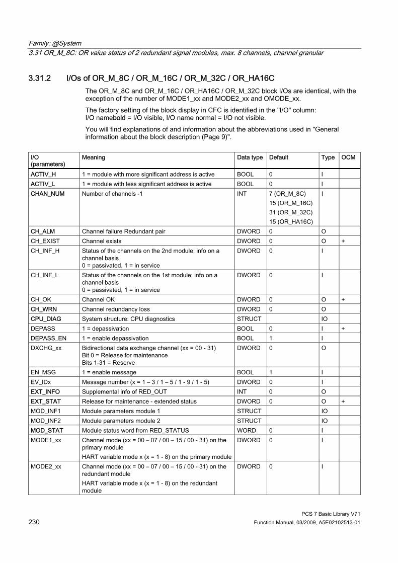
Family: @System 3.31 OR_M_8C: OR value status of 2 redundant signal modules, max. 8 channels, channel granular
PCS 7 Basic Library V71 230 Function Manual, 03/2009, A5E02102513-01
3.31.2 I/Os of OR_M_8C / OR_M_16C / OR_M_32C / OR_HA16C The OR_M_8C and OR_M_16C / OR_HA16C / OR_M_32C block I/Os are identical, with the exception of the number of MODE1_xx and MODE2_xx and OMODE_xx. The factory setting of the block display in CFC is identified in the "I/O" column: I/O namebold = I/O visible, I/O name normal = I/O not visible. You will find explanations of and information about the abbreviations used in "General information about the block description (Page 9)".
I/O (parameters)
Meaning Data type Default Type OCM
ACTIV_H 1 = module with more significant address is active BOOL 0 I ACTIV_L 1 = module with less significant address is active BOOL 0 I CHAN_NUM Number of channels -1 INT 7 (OR_M_8C)
15 (OR_M_16C) 31 (OR_M_32C) 15 (OR_HA16C)
I
CH_ALM Channel failure Redundant pair DWORD 0 O CH_EXIST Channel exists DWORD 0 O + CH_INF_H Status of the channels on the 2nd module; info on a
channel basis 0 = passivated, 1 = in service
DWORD 0 I
CH_INF_L Status of the channels on the 1st module; info on a channel basis 0 = passivated, 1 = in service
DWORD 0 I
CH_OK Channel OK DWORD 0 O + CH_WRN Channel redundancy loss DWORD 0 O CPU_DIAG System structure: CPU diagnostics STRUCT IO DEPASS 1 = depassivation BOOL 0 I + DEPASS_EN 1 = enable depassivation BOOL 1 I DXCHG_xx Bidirectional data exchange channel (xx = 00 - 31)
Bit 0 = Release for maintenance Bits 1-31 = Reserve
DWORD 0 O
EN_MSG 1 = enable message BOOL 1 I EV_IDx Message number (x = 1 – 3 / 1 – 5 / 1 - 9 / 1 - 5) DWORD 0 I EXT_INFO Supplemental info of RED_OUT INT 0 O EXT_STAT Release for maintenance - extended status DWORD 0 O + MOD_INF1 Module parameters module 1 STRUCT IO MOD_INF2 Module parameters module 2 STRUCT IO MOD_STAT Module status word from RED_STATUS WORD 0 I MODE1_xx Channel mode (xx = 00 – 07 / 00 – 15 / 00 - 31) on the
primary module HART variable mode x (x = 1 - 8) on the primary module
DWORD 0 I
MODE2_xx Channel mode (xx = 00 – 07 / 00 – 15 / 00 - 31) on the redundant module HART variable mode x (x = 1 - 8) on the redundant module
DWORD 0 I

Family: @System 3.31 OR_M_8C: OR value status of 2 redundant signal modules, max. 8 channels, channel granular
PCS 7 Basic Library V71 Function Manual, 03/2009, A5E02102513-01 231
I/O (parameters)
Meaning Data type Default Type OCM
MS Maintenance status DWORD 0 I + MSG_ACKx Message acknowledgement ALARM_8P_x
(x = 1 – 3 / 1 – 5 / 1 - 9 / 1 - 5) WORD 0 O
MSG_STATx Message error information ALARM_8P_x (x = 1 – 3 / 1 – 5 / 1 - 9 / 1 - 5)
WORD 0 O
O_MS Maintenance status DWORD 0 O OMODE_xx Channel mode (xx = 00 – 07 / 00 – 15 / 00 - 31)
mode HART variable x (x = 1 - 8) DWORD 0 O
QDISCREP 1 = At least one channel pair does not match BOOL 0 O QERR 1 = program runtime error
(cannot determine module status) BOOL 1 O
QMODF1 1 = error module 1 BOOL 0 O QMODF2 1 = error module 2 BOOL 0 O QPASS 1 = at least one module is passivated BOOL 0 O + RACKF1 1 = error rack 1 BOOL 0 I RACKF2 1 = error rack 2 BOOL 0 I RED_STAT Value returned by the RED_STATUS block INT 0 I RETURN_VAL Error information from RED_OUT INT 0 O
Additional information For further information, refer to the following sections: Maintenance status of MS (Page 326) Message texts and associated values of OR_M_8C Message texts and associated values of OR_M_16C Message texts and associated values of OR_HA16C Message texts and associated values of OR_M_32C General information about the block description

Family: @System 3.31 OR_M_8C: OR value status of 2 redundant signal modules, max. 8 channels, channel granular
PCS 7 Basic Library V71 232 Function Manual, 03/2009, A5E02102513-01
3.31.3 Message texts and associated values of OR_M_8C
Assignment of message text and message class (Page 324) Message block ALARM_8P
Message number
Default message text Message class
1 Module @1%d@/ @2%d@/ @3%d@: Failure of module redundancy pair
S
2 Module @1%d@/ @2%d@/ @3%d@: Module redundancy loss
F
3 Module @1%d@/ @2%d@/ @3%d@: Cannot determine module status
S
EV_ID1
4 Module @1%d@/ @2%d@/ @3%d@: At least one channel pair does not match
M
1 Module @1%d@/ @2%d@/ @3%d@: Failure of redundancy pair on channel 00
S
2 Module @1%d@/ @2%d@/ @3%d@: Failure of redundancy pair on channel 01
S
3 Module @1%d@/ @2%d@/ @3%d@: Failure of redundancy pair on channel 02
S
4 Module @1%d@/ @2%d@/ @3%d@: Failure of redundancy pair on channel 03
S
5 Module @1%d@/ @2%d@/ @3%d@: Failure of redundancy pair on channel 04
S
6 Module @1%d@/ @2%d@/ @3%d@: Failure of redundancy pair on channel 05
S
7 Module @1%d@/ @2%d@/ @3%d@: Failure of redundancy pair on channel 06
S
EV_ID2
8 Module @1%d@/ @2%d@/ @3%d@: Failure of redundancy pair on channel 07
S
1 Module @1%d@/ @2%d@/ @3%d@: Redundancy loss on channel 00
F
2 Module @1%d@/ @2%d@/ @3%d@: Redundancy loss on channel 01
F
3 Module @1%d@/ @2%d@/ @3%d@: Redundancy loss on channel 02
F
4 Module @1%d@/ @2%d@/ @3%d@: Redundancy loss on channel 03
F
5 Module @1%d@/ @2%d@/ @3%d@: Redundancy loss on channel 04
F
6 Module @1%d@/ @2%d@/ @3%d@: Redundancy loss on channel 05
F
7 Module @1%d@/ @2%d@/ @3%d@: Redundancy loss on channel 06
F
EV_ID3
8 Module @1%d@/ @2%d@/ @3%d@: Redundancy loss on channel 07
F

Family: @System 3.31 OR_M_8C: OR value status of 2 redundant signal modules, max. 8 channels, channel granular
PCS 7 Basic Library V71 Function Manual, 03/2009, A5E02102513-01 233
Assignment of associated values Message block ALARM_8P
Associated value
Block parameters Meaning
1 SUBN_ID DP master system ID (byte) 2 RACK_NO Rack/station number (byte)
EV_ID1 / 2 / 3
3 SLOT_NO Slot number (byte)
Redundancy loss causes the geographic address of the failed module to be entered dynamically. If both modules fail, the message text will always contain the geographic address of the primary module.

Family: @System 3.32 PADP_L0x: Monitoring DP/PA slaves
PCS 7 Basic Library V71 234 Function Manual, 03/2009, A5E02102513-01
3.32 PADP_L0x: Monitoring DP/PA slaves
3.32.1 Description of PADP_L00
Object name (type + number) FB 109 ● PADP_L00 block I/Os (Page 238)
Field of application Block PADP_L00 monitors DP/PA field devices operating as DPV0 or DPV1 slaves downstream of a DP/PA or Y-Link that is operated as a DPV0 slave. The PA field devices must conform to the PROFIBUS V3.0 profile. Individual blocks must be available for the diagnostic and signal processing functions of DP field devices. H systems support only the PA field devices at an active DP/PA-Link.
Calling OBs The block must be installed in the run sequence in the following OBs: OB 1 Cyclic program OB 82 Diagnostic interrupt OB 85 Program runtime error OB 86 Rack failure OB100 Restart (warm start)
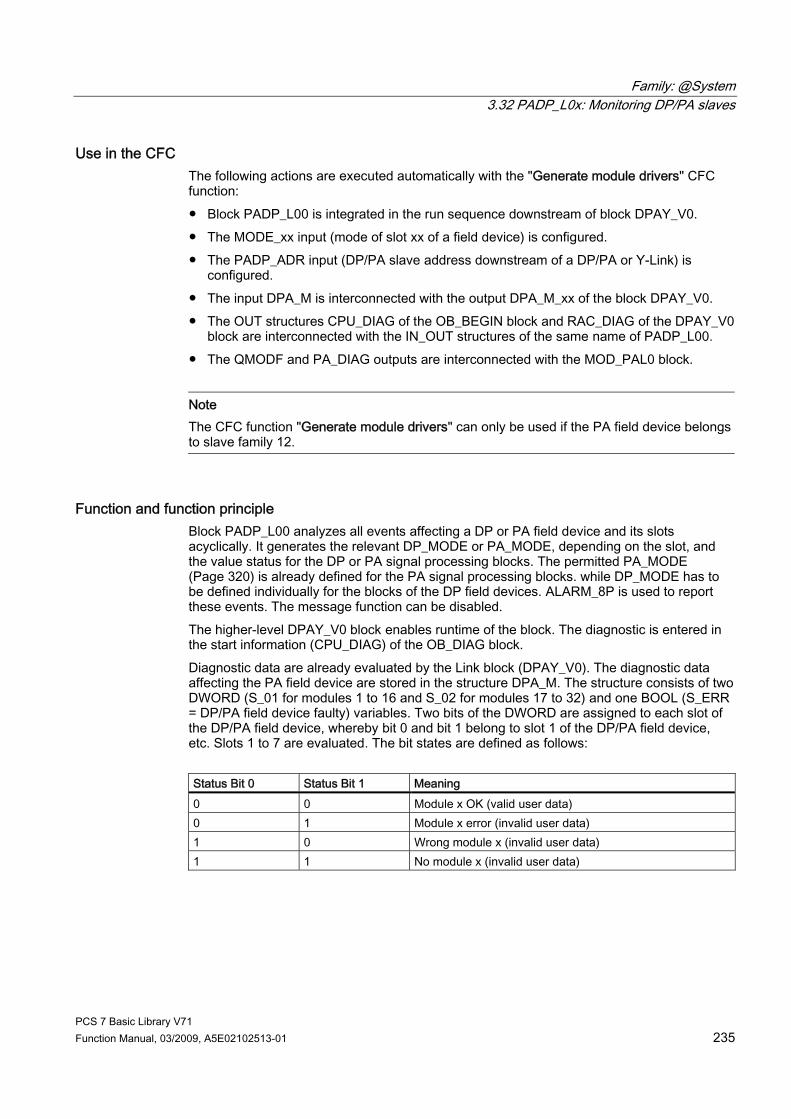
Family: @System 3.32 PADP_L0x: Monitoring DP/PA slaves
PCS 7 Basic Library V71 Function Manual, 03/2009, A5E02102513-01 235
Use in the CFC The following actions are executed automatically with the "Generate module drivers" CFC function: ● Block PADP_L00 is integrated in the run sequence downstream of block DPAY_V0. ● The MODE_xx input (mode of slot xx of a field device) is configured. ● The PADP_ADR input (DP/PA slave address downstream of a DP/PA or Y-Link) is
configured. ● The input DPA_M is interconnected with the output DPA_M_xx of the block DPAY_V0. ● The OUT structures CPU_DIAG of the OB_BEGIN block and RAC_DIAG of the DPAY_V0
block are interconnected with the IN_OUT structures of the same name of PADP_L00. ● The QMODF and PA_DIAG outputs are interconnected with the MOD_PAL0 block.
Note The CFC function "Generate module drivers" can only be used if the PA field device belongs to slave family 12.
Function and function principle Block PADP_L00 analyzes all events affecting a DP or PA field device and its slots acyclically. It generates the relevant DP_MODE or PA_MODE, depending on the slot, and the value status for the DP or PA signal processing blocks. The permitted PA_MODE (Page 320) is already defined for the PA signal processing blocks. while DP_MODE has to be defined individually for the blocks of the DP field devices. ALARM_8P is used to report these events. The message function can be disabled. The higher-level DPAY_V0 block enables runtime of the block. The diagnostic is entered in the start information (CPU_DIAG) of the OB_DIAG block. Diagnostic data are already evaluated by the Link block (DPAY_V0). The diagnostic data affecting the PA field device are stored in the structure DPA_M. The structure consists of two DWORD (S_01 for modules 1 to 16 and S_02 for modules 17 to 32) and one BOOL (S_ERR = DP/PA field device faulty) variables. Two bits of the DWORD are assigned to each slot of the DP/PA field device, whereby bit 0 and bit 1 belong to slot 1 of the DP/PA field device, etc. Slots 1 to 7 are evaluated. The bit states are defined as follows: Status Bit 0 Status Bit 1 Meaning 0 0 Module x OK (valid user data) 0 1 Module x error (invalid user data) 1 0 Wrong module x (invalid user data) 1 1 No module x (invalid user data)

Family: @System 3.32 PADP_L0x: Monitoring DP/PA slaves
PCS 7 Basic Library V71 236 Function Manual, 03/2009, A5E02102513-01
An input (MODE_xx) exists for each slot (module) of the DP/PA field device that is used to read in HW Config data for the slots (modules). At DP field devices the user must enter his code manually at the MODE input. The function writes MODE_xx to the low word of the OMODE_xx (Page 312) output parameter. This occurs only during startup or if you set ACC_MODE = TRUE. The actual slot value status is written to the most significant byte. If the result is positive, the system sets OMODE_xx = 16#80xxxxxx. The following events are evaluated by block DPAY_V0 and lead to the value status “Invalid value” due to a higher-level error (OMODE_xx = 16#40xxxxxx): • Rack failure (OB 86) (output parameter QRACKF = TRUE)
• Diagnostic interrupt affecting an entire field device (OB 82)
(output parameter QMODF = TRUE if DPA_M.S_ERR = TRUE)
• Diagnostic interrupt slot xx affecting a field device (OB 82):
(output parameter OMODE_xx = Module-(slot-)error-specific DPA_M)
In the event of a diagnostic interrupt, the block reports field-device-specifically to WinCC by means of ALARM_8P. It distinguishes between the field device and its slots, and assigns a message number to each slot. The “Device failure” message can be disabled with EM_MSG_D = FALSE.
Redundancy Higher-level block DPAY_V0 evaluates the redundancy of DP master systems operating in an H system.
MODE Setting for PA Profiles You can find additional information in "PA_MODE Settings (Page 320)".
Note Modifications of parameters at the MODE_xx inputs during runtime are not accepted at the outputs until input ACC_MODE = 1.
OMODE Structure You can find additional information in "OMODE (Page 312)".
Error handling The plausibility of input parameters is not checked.
Startup characteristics After a restart or an initial start the system verifies that the PA field device is available under its logical base address. A restart (OB100) is reported via the LSB in byte 2 of the OMODE_xx (Page 312) outputs.

Family: @System 3.32 PADP_L0x: Monitoring DP/PA slaves
PCS 7 Basic Library V71 Function Manual, 03/2009, A5E02102513-01 237
Time response n.a.
Message functionality The block uses ALARM_8P to report field device errors and generates the following messages in the OBs listed below: OB no. Start Event Message OB 1 Cyclic processing Repeat the update of ALARM_8P outputs/messages, if
necessary OB 82 Diagnostic interrupt Device error incoming/outgoing
Device module xx error incoming/outgoing Device module xx incorrect incoming/outgoing Device module xx missing incoming/outgoing
OB 100 Restart Initialization of ALARM_8P
Operator control and monitoring The block has no faceplate. Note: If you selected the "Enable operator control and monitoring" option in the block object properties in the CFC, the variables transferred to the OS are identified under "I/Os of ..." (OCM column, "+"). Default: Option not activated.
Additional information For further information, refer to the following sections: Message texts and associated values for PADP_L00 (Page 239)
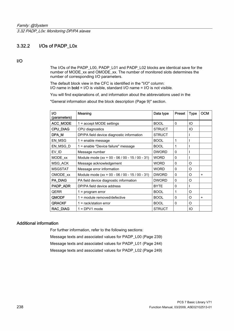
Family: @System 3.32 PADP_L0x: Monitoring DP/PA slaves
PCS 7 Basic Library V71 238 Function Manual, 03/2009, A5E02102513-01
3.32.2 I/Os of PADP_L0x
I/O The I/Os of the PADP_L00, PADP_L01 and PADP_L02 blocks are identical save for the number of MODE_xx and OMODE_xx. The number of monitored slots determines the number of corresponding I/O parameters. The default block view in the CFC is identified in the "I/O" column: I/O name in bold = I/O is visible, standard I/O name = I/O is not visible. You will find explanations of, and information about the abbreviations used in the "General information about the block description (Page 9)" section. I/O (parameters)
Meaning
Data type
Preset Type
OCM
ACC_MODE 1 = accept MODE settings BOOL 0 IO CPU_DIAG CPU diagnostics STRUCT IO DPA_M DP/PA field device diagnostic information STRUCT I EN_MSG 1 = enable message BOOL 1 I EN_MSG_D 1 = enable "Device failure" message BOOL 1 I EV_ID Message number DWORD 0 I MODE_xx Module mode (xx = 00 - 06 / 00 - 15 / 00 - 31) WORD 0 I MSG_ACK Message acknowledgement WORD 0 O MSGSTAT Message error information WORD 0 O OMODE_xx Module mode (xx = 00 - 06 / 00 - 15 / 00 - 31) DWORD 0 O + PA_DIAG PA field device diagnostic information DWORD 0 O PADP_ADR DP/PA field device address BYTE 0 I QERR 1 = program error BOOL 1 O QMODF 1 = module removed/defective BOOL 0 O + QRACKF 1 = rack/station error BOOL 0 O RAC_DIAG 1 = DPV1 mode STRUCT IO
Additional information For further information, refer to the following sections: Message texts and associated values for PADP_L00 (Page 239) Message texts and associated values for PADP_L01 (Page 244) Message texts and associated values for PADP_L02 (Page 249)
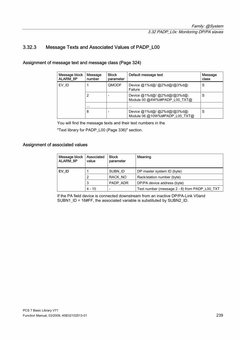
Family: @System 3.32 PADP_L0x: Monitoring DP/PA slaves
PCS 7 Basic Library V71 Function Manual, 03/2009, A5E02102513-01 239
3.32.3 Message Texts and Associated Values of PADP_L00
Assignment of message text and message class (Page 324) Message block ALARM_8P
Message number
Block parameter
Default message text
Message class
1 QMODF Device @1%d@/ @2%d@/@3%d@: Failure
S
2 - Device @1%d@/ @2%d@/@3%d@: Module 00 @4W%t#PADP_L00_TXT@
S
... ...
EV_ID
8 - Device @1%d@/ @2%d@/@3%d@: Module 06 @10W%t#PADP_L00_TXT@
S
You will find the message texts and their text numbers in the "Text library for PADP_L00 (Page 336)" section.
Assignment of associated values Message block ALARM_8P
Associated value
Block parameter
Meaning
1 SUBN_ID DP master system ID (byte) 2 RACK_NO Rack/station number (byte) 3 PADP_ADR DP/PA device address (byte)
EV_ID
4 - 10 - Text number (message 2 - 8) from PADP_L00_TXT
If the PA field device is connected downstream from an inactive DP/PA-Link V0and SUBN1_ID = 16#FF, the associated variable is substituted by SUBN2_ID.

Family: @System 3.32 PADP_L0x: Monitoring DP/PA slaves
PCS 7 Basic Library V71 240 Function Manual, 03/2009, A5E02102513-01
3.32.4 Description of PADP_L01
Object name (type + number) FB 110 ● PADP_L01 block I/Os (Page 238)
Area of application The PADP_L01 monitors DP/PA field devices that are used as DPV0 or DPV1 slaves, downstream of a DP/PA or Y link that is used as a DPV0 slave. The PA field devices must conform to the PROFIBUS V3.0 profile. There must be individual blocks available for the diagnostics and signal processing for DP field devices. H systems support only the PA field devices at an active DP/PA-Link.
Calling OBs The block must be installed in the run sequence in the following OBs (this is done automatically in the CC): OB 1 Cyclic program OB 82 Diagnostic interrupt OB 85 Program runtime error OB 86 Rack failure OB 100 Warm restart
Use in the CFC The following actions are executed automatically with the "Generate module drivers" CFC function: ● The PADP_L01 block is integrated in the run sequence downstream of block DPAY_V0. ● Parameters are assigned to the MODE_xx input (mode of slot xx of a field device). ● The PADP_ADR input (DP/PA slave address downstream of the DP/PA link or Y link) is
configured. ● The DPA_M input is interconnected with the DPA_Mxx output of the DPAY_V0 block. ● The OUT structures CPU_DIAG of the OB_BEGIN block and RAC_DIAG of the DPAY_V0
block are interconnected with the IN_OUT structures of the same name of PADP_L01. ● The outputs QMODF and PA_DIAG are interconnected with the MOD_PAL0 block.
Note The CFC function "Generate module drivers" can only be used if the PA field device belongs to slave family 12.
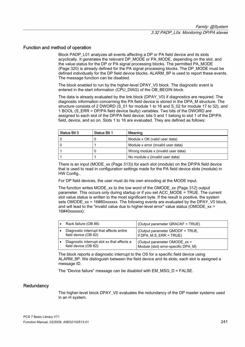
Family: @System 3.32 PADP_L0x: Monitoring DP/PA slaves
PCS 7 Basic Library V71 Function Manual, 03/2009, A5E02102513-01 241
Function and method of operation Block PADP_L01 analyzes all events affecting a DP or PA field device and its slots acyclically. It generates the relevant DP_MODE or PA_MODE, depending on the slot, and the value status for the DP or PA signal processing blocks. The permitted PA_MODE (Page 320) is already defined for the PA signal processing blocks. The DP_MODE must be defined individually for the DP field device blocks. ALARM_8P is used to report these events. The message function can be disabled. The block enabled to run by the higher-level DPAY_V0 block. The diagnostic event is entered in the start information (CPU_DIAG) of the OB_BEGIN block. The data is already evaluated by the link block (DPAY_V0) if diagnostics are required. The diagnostic information concerning the PA field device is stored in the DPA_M structure. The structure consists of 2 DWORD (S_01 for module 1 to 16 and S_02 for module 17 to 32), and 1 BOOL (S_ERR = DP/PA field device faulty) variables. Two bits of the DWORD are assigned to each slot of the DP/PA field device; bits 0 and 1 belong to slot 1 of the DP/PA field, device, and so on. Slots 1 to 16 are evaluated. They are defined as follows: Status Bit 0 Status Bit 1 Meaning 0 0 Module x OK (valid user data) 0 1 Module x error (invalid user data) 1 0 Wrong module x (invalid user data) 1 1 No module x (invalid user data)
There is an input (MODE_xx (Page 313)) for each slot (module) on the DP/PA field device that is used to read in configuration settings made for the PA field device slots (module) in HW Config.. For DP field devices, the user must do his own encoding at the MODE input. The function writes MODE_xx to the low word of the OMODE_xx (Page 312) output parameter. This occurs only during startup or if you set ACC_MODE = TRUE. The current slot value status is written to the most significant byte. If the result is positive, the system sets OMODE_xx = 16#80xxxxxx. The following events are evaluated by the DPAY_V0 block, and will lead to the "invalid value due to higher-level error" value status (OMODE_xx = 16#40xxxxxx): • Rack failure (OB 86) (Output parameter QRACKF = TRUE)
• Diagnostic interrupt that affects entire field device (OB 82)
(Output parameter QMODF = TRUE, if DPA_M.S_ERR = TRUE)
• Diagnostic interrupt slot xx that affects a field device (OB 82):
(Output parameter OMODE_xx = Module (slot) error-specific DPA_M)
The block reports a diagnostic interrupt to the OS for a specific field device using ALARM_8P. We distinguish between the field device and its slots; each slot is assigned a message ID. The “Device failure” message can be disabled with EM_MSG_D = FALSE.
Redundancy The higher-level block DPAY_V0 evaluates the redundancy of the DP master systems used in an H system.
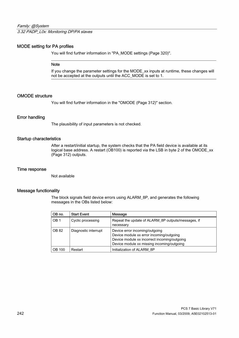
Family: @System 3.32 PADP_L0x: Monitoring DP/PA slaves
PCS 7 Basic Library V71 242 Function Manual, 03/2009, A5E02102513-01
MODE setting for PA profiles You will find further information in "PA_MODE settings (Page 320)".
Note If you change the parameter settings for the MODE_xx inputs at runtime, these changes will not be accepted at the outputs until the ACC_MODE is set to 1.
OMODE structure You will find further information in the "OMODE (Page 312)" section.
Error handling The plausibility of input parameters is not checked.
Startup characteristics After a restart/initial startup, the system checks that the PA field device is available at its logical base address. A restart (OB100) is reported via the LSB in byte 2 of the OMODE_xx (Page 312) outputs.
Time response Not available
Message functionality The block signals field device errors using ALARM_8P, and generates the following messages in the OBs listed below: OB no. Start Event Message OB 1 Cyclic processing Repeat the update of ALARM_8P outputs/messages, if
necessary OB 82 Diagnostic interrupt Device error incoming/outgoing
Device module xx error incoming/outgoing Device module xx incorrect incoming/outgoing Device module xx missing incoming/outgoing
OB 100 Restart Initialization of ALARM_8P

Family: @System 3.32 PADP_L0x: Monitoring DP/PA slaves
PCS 7 Basic Library V71 Function Manual, 03/2009, A5E02102513-01 243
Operator control and monitoring The block has no faceplate. Note: If you selected the "Enable operator control and monitoring" option in the block object properties in the CFC, the variables transferred to the OS are identified under "I/Os of ..." (OCM column, "+"). Default: Option not activated.
Additional information For further information, refer to the following sections: Message texts and associated values for PADP_L01 (Page 244)

Family: @System 3.32 PADP_L0x: Monitoring DP/PA slaves
PCS 7 Basic Library V71 244 Function Manual, 03/2009, A5E02102513-01
3.32.5 Message Texts and Associated Values of PADP_L01
Assignment of message text and message class (Page 324) Message block ALARM_8P
Message number
Block parameter
Default message text
Message class
1 QMODF Device @1%d@/ @2%d@/@3%d@: Failure
S
2 - Device @1%d@/ @2%d@/@3%d@: Module 07 @4W%t#PADP_L01_TXT@
S
EV_ID1
3 - Device @1%d@/ @2%d@/@3%d@: Module 15 @4W%t#PADP_L01_TXT@
S
1 - Device @1%d@/ @2%d@/@3%d@: Module 00 @4W%t#PADP_L01_TXT@
S
... ...
EV_ID2
7 - Device @1%d@/ @2%d@/@3%d@: Module 06 @10W%t#PADP_L01_TXT@
S
1 - Device @1%d@/ @2%d@/@3%d@: Module 08 @4W%t#PADP_L01_TXT@
S
... ...
EV_ID3
7 - Device @1%d@/ @2%d@/@3%d@: Module 14 @10W%t#PADP_L01_TXT@
S
You will find the message texts and their text numbers in the "Text library for PADP_L01 (Page 336)" section.
Assignment of associated values Message block ALARM_8P
Associated value
Block parameter
Meaning
1 SUBN_ID DP master system ID (byte) 2 RACK_NO Rack/station number (byte) 3 PADP_ADR DP/PA device address (byte)
EV_ID1
4 - 5 - Text number (message 2 - 3) from PADP_L01_TXT 1 SUBN_ID DP master system ID (byte) 2 RACK_NO Rack/station number (byte) 3 PADP_ADR DP/PA device address (byte)
EV_ID2
4 - 10 - Text number (message 1 - 7) from PADP_L01_TXT 1 SUBN_ID DP master system ID (byte) 2 RACK_NO Rack/station number (byte) 3 PADP_ADR DP/PA device address (byte)
EV_ID3
4 - 10 - Text number (message 1 - 7) from PADP_L01_TXT
If the PA field device is connected downstream from an inactive DP/PA-Link V0and SUBN1_ID = 16#FF, the associated variable is substituted by SUBN2_ID.

Family: @System 3.32 PADP_L0x: Monitoring DP/PA slaves
PCS 7 Basic Library V71 Function Manual, 03/2009, A5E02102513-01 245
3.32.6 Description of PADP_L02
Object name (type + number) FB 111 ● PADP_L02 block I/Os (Page 238)
Area of application The PADP_L02 monitors DP/PA field devices that are used as DPV0 or DPV1 slaves, downstream of a DP/PA or Y link that is used as a DPV0 slave. The PA field devices must conform to the PROFIBUS V3.0 profile. There must be individual blocks available for the diagnostics and signal processing for DP field devices. H systems support only the PA field devices at an active DP/PA-Link.
Calling OBs The PADP_L02 block must be installed in the run sequence in the following OBs: OB 1 Cyclic program OB 82 Diagnostic interrupt OB 85 Program runtime error OB 86 Rack failure OB 100 Warm restart
Use in the CFC The following actions are executed automatically with the "Generate module drivers" CFC function: ● The PADP_L02 block is integrated in the run sequence downstream of block DPAY_V0. ● Parameters are assigned to the MODE_xx input (mode of slot xx of a field device). ● The PADP_ADR input (DP/PA slave address downstream of the DP/PA link or Y link) is
configured. ● The DPA_M input is interconnected with the DPA_Mxx output of the DPAY_V0 block. ● The OUT structures CPU_DIAG of the OB_BEGIN block and RAC_DIAG of the DPAY_V0
block are interconnected with the IN_OUT structures of the same name of PADP_L02. ● The QMODF and PA_DIAG outputs are interconnected with the MOD_PAL0 block.

Family: @System 3.32 PADP_L0x: Monitoring DP/PA slaves
PCS 7 Basic Library V71 246 Function Manual, 03/2009, A5E02102513-01
Function and method of operation Block PADP_L02 analyzes all events affecting a DP or PA field device and its slots acyclically. It generates the relevant DP_MODE or PA_MODE, depending on the slot, and the value status for the DP or PA signal processing blocks. The permitted PA_MODE (Page 320) is already defined for the PA signal processing blocks. The DP_MODE must be defined individually for the DP field device blocks. ALARM_8P is used to report these events. The message function can be disabled. The block enabled to run by the higher-level DPAY_V0 block. The event to be evaluated is entered in the start information (CPU_DIAG) of OB_BEGIN. The data is already evaluated by the link block (DPAY_V0) if diagnostics are required. The diagnostic information concerning the PA field device is stored in the DPA_M structure. The structure consists of 2 DWORD (S_01 for module 1 to 16 and S_02 for module 17 to 32), and 1 BOOL (S_ERR = DP/PA field device faulty) variables. Two bits of the DWORD are assigned to each slot of the DP/PA field device; bits 0 and 1 belong to slot 1 of the DP/PA field, device, and so on. Slots 1 to 32 are evaluated. They are defined as follows: Status Bit 0 Status Bit 1 Meaning 0 0 Module x OK (valid user data) 0 1 Module x error (invalid user data) 1 0 Wrong module x (invalid user data) 1 1 No module x (invalid user data)
There is an input (MODE_xx) for each slot (module) on the DP/PA field device that is used to read in configuration settings made for the PA field device slots (module) in HW Config.. For DP field devices, the user must do his own encoding at the MODE input. The function writes MODE_xx to the low word of the OMODE_xx (Page 312) output parameter. This occurs only during startup or if you set ACC_MODE = TRUE. The current slot value status is written to the most significant byte. If the result is positive, the system sets OMODE_xx = 16#80xxxxxx. The following events are evaluated by the DPAY_V0 block, and will lead to the "invalid value due to higher-level error" value status (OMODE_xx = 16#40xxxxxx): • Rack failure (OB 86) (Output parameter QRACKF = TRUE)
• Diagnostic interrupt that affects entire field device (OB 82)
(Output parameter QMODF = TRUE, if DPA_M.S_ERR = TRUE)
• Diagnostic interrupt slot xx that affects a field device (OB 82):
(Output parameter OMODE_xx = Module (slot) error-specific DPA_M)
The block reports a diagnostic interrupt to WinCC for a specific field device using ALARM_8P. We distinguish between the field device and its slots; each slot is assigned a message ID. The “Device failure” message can be disabled with EM_MSG_D = FALSE.
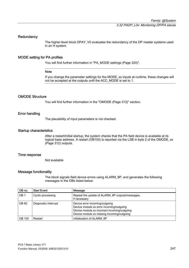
Family: @System 3.32 PADP_L0x: Monitoring DP/PA slaves
PCS 7 Basic Library V71 Function Manual, 03/2009, A5E02102513-01 247
Redundancy The higher-level block DPAY_V0 evaluates the redundancy of the DP master systems used in an H system.
MODE setting for PA profiles You will find further information in "PA_MODE settings (Page 320)".
Note If you change the parameter settings for the MODE_xx inputs at runtime, these changes will not be accepted at the outputs until the ACC_MODE is set to 1.
OMODE Structure You will find further information in the "OMODE (Page 312)" section.
Error handling The plausibility of input parameters is not checked.
Startup characteristics After a restart/initial startup, the system checks that the PA field device is available at its logical base address. A restart (OB100) is reported via the LSB in byte 2 of the OMODE_xx (Page 312) outputs.
Time response Not available
Message functionality The block signals field device errors using ALARM_8P, and generates the following messages in the OBs listed below:
OB no. Start Event Message OB 1 Cyclic processing Repeat the update of ALARM_8P outputs/messages,
if necessary OB 82 Diagnostic interrupt Device error incoming/outgoing
Device module xx error incoming/outgoing Device module xx incorrect incoming/outgoing Device module xx missing incoming/outgoing
OB 100 Restart Initialization of ALARM_8P

Family: @System 3.32 PADP_L0x: Monitoring DP/PA slaves
PCS 7 Basic Library V71 248 Function Manual, 03/2009, A5E02102513-01
Operator control and monitoring The block has no faceplate. Note: If you selected the "Enable operator control and monitoring" option in the block object properties in the CFC, the variables transferred to the OS are identified under "I/Os of ..." (OCM column, "+"). Default: Option not activated.
Additional information For further information, refer to the following sections: Message texts and associated values for PADP_L02 (Page 249)

Family: @System 3.32 PADP_L0x: Monitoring DP/PA slaves
PCS 7 Basic Library V71 Function Manual, 03/2009, A5E02102513-01 249
3.32.7 Message Texts and Associated Values of PADP_L02
Assignment of message text and message class (Page 324) Message block ALARM_8P
Message number
Block parameter
Default message text
Message class
1 QMODF Device @1%d@/ @2%d@/@3%d@: Failure
S
2 - Device @1%d@/ @2%d@/@3%d@: Module 07 @4W%t#PADP_L02_TXT@
S
3 - Device @1%d@/ @2%d@/@3%d@: Module 15 @4W%t#PADP_L02_TXT@
S
4 - Device @1%d@/ @2%d@/@3%d@: Module 23 @6W%t#PADP_L02_TXT@
S
EV_ID1
5 - Device @1%d@/ @2%d@/@3%d@: Module 31 @7W%t#PADP_L02_TXT@
S
1 - Device @1%d@/ @2%d@/@3%d@: Module 00 @4W%t#PADP_L02_TXT@
S
... ...
EV_ID2
7 - Device @1%d@/ @2%d@/@3%d@: Module 06 @10W%t#PADP_L02_TXT@
S
1 - Device @1%d@/ @2%d@/@3%d@: Module 08 @4W%t#PADP_L02_TXT@
S
... ...
EV_ID3
7 - Device @1%d@/ @2%d@/@3%d@: Module 14 @10W%t#PADP_L02_TXT@
S
1 - Device @1%d@/ @2%d@/@3%d@: Module 16 @4W%t#PADP_L02_TXT@
S
... ...
EV_ID4
- Device @1%d@/ @2%d@/@3%d@: Module 22 @10W%t#PADP_L02_TXT@
S
1 - Device @1%d@/ @2%d@/@3%d@: Module 24 @4W%t#PADP_L02_TXT@
S
... ...
EV_ID5
7 - Device @1%d@/ @2%d@/@3%d@: Module 30 @10W%t#PADP_L02_TXT@
S
You will find the message texts and their text numbers in "Text library for PADP_L02 (Page 336)".

Family: @System 3.32 PADP_L0x: Monitoring DP/PA slaves
PCS 7 Basic Library V71 250 Function Manual, 03/2009, A5E02102513-01
Assignment of associated values to the block parameters of PADP_L02 Message block ALARM_8P
Associated value
Block parameter
Meaning
1 SUBN_ID DP master system ID (byte) 2 RACK_NO Rack/station number (byte) 3 PADP_ADR DP/PA device address (byte)
EV_ID1
4 - 7 - Text number (message 2 - 5) from PADP_L02_TXT 1 SUBN_ID DP master system ID (byte) 2 RACK_NO Rack/station number (byte) 3 PADP_ADR DP/PA device address (byte)
EV_ID2
4 - 10 - Text number (message 1 - 7) from PADP_L02_TXT 1 SUBN_ID DP master system ID (byte) 2 RACK_NO Rack/station number (byte) 3 PADP_ADR DP/PA device address (byte)
EV_ID3
4 - 10 - Text number (message 1 - 7) from PADP_L02_TXT 1 SUBN_ID DP master system ID (byte) 2 RACK_NO Rack/station number (byte) 3 PADP_ADR DP/PA device address (byte)
EV_ID4
4 - 10 - Text number (message 1 - 7) from PADP_L02_TXT 1 SUBN_ID DP master system ID (byte) 2 RACK_NO Rack/station number (byte) 3 PADP_ADR DP/PA device address (byte)
EV_ID5
4 - 10 - Text number (message 1 - 7) from PADP_L02_TXT
If the PA field device is connected downstream from an inactive DP/PA-Link V0and SUBN1_ID = 16#FF, the associated variable is substituted by SUBN2_ID.

Family: @System 3.33 PADP_L10: Monitoring PA slaves downstream of DPV0 with up to 16 slots
PCS 7 Basic Library V71 Function Manual, 03/2009, A5E02102513-01 251
3.33 PADP_L10: Monitoring PA slaves downstream of DPV0 with up to 16 slots
3.33.1 Description of PADP_L10
Object name (type + number) FB 116 ● PADP_L10 block I/Os (Page 257)
Area of application Block PADP_L10 monitors DPV0 PA field devices with a maximum of 16 slots, which are operated as DPV0 slaves on a DP master system, either directly or via a DP/PA coupler. The DP/PA coupler is connected downstream of a DPV1 DP/PA link. The PA field devices must conform to the PROFIBUS V3.0 profile. H systems support only the PA field devices at an active DP/PA-Link.
Calling OBs The block must be installed in the run sequence downstream from the OB_DIAG1 block in the following OBs (this is done automatically in the CFC): OB 1 Cyclic program OB 55 Status interrupt (only if a PA slave is required) OB 56 Update interrupt (only if a PA slave is required) OB 57 Vendor-specific interrupt (only if a PA slave is required) OB 82 Diagnostic interrupt OB 83 Remove/insert module interrupt (failure/return of a field device) OB 85 Program runtime error OB 86 Rack failure OB 100 Warm restart

Family: @System 3.33 PADP_L10: Monitoring PA slaves downstream of DPV0 with up to 16 slots
PCS 7 Basic Library V71 252 Function Manual, 03/2009, A5E02102513-01
Use in the CFC The following actions are executed automatically with the "Generate module drivers" CFC function: ● Block OB_DIAG1 is installed in the run sequence upstream of PADP_L10. ● The following are configured, depending on whether the PA field device is connected
directly to a DP master system or downstream of a DP/PA link: – the diagnostic address of the PA field device or of the DADDR DP/PA link – the geographic address (SUBN1_ID, SUBN2_ID, RACK_NO of the PA address of the
PA field device or the DP/PA link) – SLOT_NO = 0 or the geographic address of the PA field device in the DP/PA link
(SLOT0_NO = Slot 0 no. for the PA field device, SLOTS_NO = number of slots of the PA field device)
– SLOTS_NO = number of slots of the PA field device – the PA address of the PA field device (PADP_ADR) – MODE_xx (mode of slot xx of a PA field device)
● The CPU_DIAG and CPU_OB_5X OUT structures of OB_BEGIN and RAC_DIAG of OB_DIAG1 are interconnected with the IN_OUT structures of the same name of PADP_L10.
● The EN input is interconnected with the output of an AND block whose inputs are interconnected with the outputs EN_SUBx (x = number of the DP master system) of the OB_BEGIN block, EN_Rxxx (xxx = rack/station number) of the SUBNET block, EN_Mx (x= number of the PA device) of the DPAY_V1 block, and EN_F of the OB_DIAG1 block.
● EN_DIAG is interconnected with output EN_DIAG of OB_DIAG1. ● Output QPERAF is interconnected with input PERAF of MOD_PAX0 or MOD_PAL0. ● Output QMODF is interconnected with input MODF of MOD_PAX0 or MOD_PAL0. ● Output PA_DIAG is interconnected with input PA_DIAG of MOD_PAX0 or MOD_PAL0.
Note The CFC function "Generate module drivers" can only be used if the PA field device belongs to slave family 12.
Description of the functions Block PADP_L10 analyzes all events affecting a PA field device acyclically. It generates the slot-specific MODE (PA_MODE (Page 320)) and the value status for signal processing blocks. The permitted PA_MODE is defined for PA field devices. If you are using modular PA field devices (DPV0), the next block (MOD_PAX0/MOD_PAL0) always reports the events in slot 0 of the PA field device in the DP/PA link. The affected MOD_PAX0/MOD_PAL0 block is enabled.

Family: @System 3.33 PADP_L10: Monitoring PA slaves downstream of DPV0 with up to 16 slots
PCS 7 Basic Library V71 Function Manual, 03/2009, A5E02102513-01 253
How it works Block PADP_L10 is enabled to run by the higher-level OB_DIAG1 block. The event to be evaluated is entered in the start information (CPU_DIAG) of OB_BEGIN. Block PADP_L10 checks the geographic address and the number of slots (SLOT_NO) of the PA field device to determine whether it is responsible for this event. For a diagnostic event (OB 82, OB 55, OB 56, OB 57), SFB 54 is used to synchronously read the data from OB_BEGIN. If diagnostic data could not be read synchronously from OB_BEGIN or when requested by OB_DIAG1 (EN_DIAG = TRUE), SFB 52 (RDREC) is used to read the current diagnostic data asynchronously. Byte 9 of the additional alarm information contains the slot number of the field device that triggered the diagnostic interrupt. The corresponding slot is enabled. The following diagnostic data is interpreted as a higher-level error in the block: Additional alarm information
Byte no. DPV1 name Bit no. Value Info Byte 1 to 6 DDLM_SLAVE_DIAG Byte 7 Header Bit 7
Bit 6 Bit 5 to bit 0
0 0 8 or optional
fixed fixed Length of diagnostic data
Byte 8 Status_Type Bit 7 Bit 6 to bit 0
1 126
Status Highest vendor- specific status, will not be used in future
Byte 9 Slot_number Slot number of the PB The PB contains the diagnostic data.
Byte 10 Specifier Bit 7 to bit 2 Bit 1 to bit 0
Reserved 1: status is displayed 2: status is not displayed
depends on the content of diagnostic data
Byte 11 to 14 Diagnostics optional Bytes 11 to 20
With a DPV0 PA field device, the diagnostic data is always assigned to slot 0. It is also possible to generate slot-specific diagnostics for DPV1 PA field devices. These have not yet been defined. With a DPV1 field device, only the field-device slot that triggered the diagnostics is enabled. Evaluation of the coding in the context of higher-level errors in the slot-specific OMODE_xx (Page 312) outputs is based solely on the diagnostic information at slot 0.
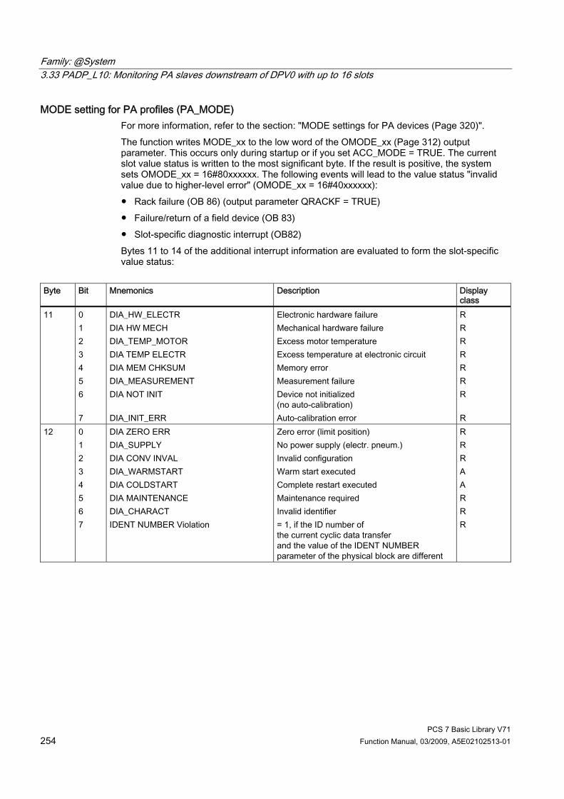
Family: @System 3.33 PADP_L10: Monitoring PA slaves downstream of DPV0 with up to 16 slots
PCS 7 Basic Library V71 254 Function Manual, 03/2009, A5E02102513-01
MODE setting for PA profiles (PA_MODE) For more information, refer to the section: "MODE settings for PA devices (Page 320)". The function writes MODE_xx to the low word of the OMODE_xx (Page 312) output parameter. This occurs only during startup or if you set ACC_MODE = TRUE. The current slot value status is written to the most significant byte. If the result is positive, the system sets OMODE_xx = 16#80xxxxxx. The following events will lead to the value status "invalid value due to higher-level error" (OMODE_xx = 16#40xxxxxx): ● Rack failure (OB 86) (output parameter QRACKF = TRUE) ● Failure/return of a field device (OB 83) ● Slot-specific diagnostic interrupt (OB82) Bytes 11 to 14 of the additional interrupt information are evaluated to form the slot-specific value status:
Byte Bit Mnemonics Description Display
class 11 0
1 2 3 4 5 6 7
DIA_HW_ELECTR DIA HW MECH DIA_TEMP_MOTOR DIA TEMP ELECTR DIA MEM CHKSUM DIA_MEASUREMENT DIA NOT INIT DIA_INIT_ERR
Electronic hardware failure Mechanical hardware failure Excess motor temperature Excess temperature at electronic circuit Memory error Measurement failure Device not initialized (no auto-calibration) Auto-calibration error
R R R R R R R R
12 0 1 2 3 4 5 6 7
DIA ZERO ERR DIA_SUPPLY DIA CONV INVAL DIA_WARMSTART DIA COLDSTART DIA MAINTENANCE DIA_CHARACT IDENT NUMBER Violation
Zero error (limit position) No power supply (electr. pneum.) Invalid configuration Warm start executed Complete restart executed Maintenance required Invalid identifier = 1, if the ID number of the current cyclic data transfer and the value of the IDENT NUMBER parameter of the physical block are different
R R R A A R R R

Family: @System 3.33 PADP_L10: Monitoring PA slaves downstream of DPV0 with up to 16 slots
PCS 7 Basic Library V71 Function Manual, 03/2009, A5E02102513-01 255
Byte Bit Mnemonics Description Display class
13 0 1 2 3 4...7
DIA_MAINTENANCE_ALARM DIA_MAINTENANCE_DEMANDED DIA_FUNCTION_CHECK DIA_INV_PRO_COND Reserved
Device error Maintenance requested Device is in function test or in simulation or is under local operator control (maintenance) The process conditions do not permit valid values to be returned. (Set if quality "Uncertain, process related, no maintenance" or "Bad, process related, no maintenance") Reserved for PNO, default 0
R R R R
14 0...4 5 6 7
Reserved PROFILE_SPECIFIC_EXTENSION _AVAILABLE MANUFACTURER_SPECIFIC _EXTENSION_AVAILABLE EXTENSION_AVAILABLE
Reserved for PNO use = 0: For devices with this profile = 0: For devices with this profile = 0: No further diagnostic information available = 1: Further diagnostic information available in DIAGNOSIS_EXTENSION
Display class R = incoming / outgoing events. Display class A = incoming events that are reset by the field device after a few cycles. All events in byte 11 and the events of bit 0, 1 and 2 in byte 12 lead to the value status “Higher-level error” (OMODE_xx (Page 312) = 16#40xxxxxx). Bytes 11, 12, 13, and 14 are entered in bytes 0 to 3 of the PA_DIAG parameter to generate messages and MS in the MOD_PAX0/MOD_PAL0 block.
Special features of PA_AO and PA_DO field devices With the field devices listed above, the PA profiles can be defined at two different slots. In this case, the driver generator will assign the mode code of the PA field device to the first slot and the mode code 16#8000 to the second at the corresponding MODE inputs of the block. The diagnostic information of the first and of the second slot are linked by a logical OR operation, which allows the generation of a uniform value status for the PA_x block.
Redundancy The higher-level block evaluates the redundancy of DP master systems operating in an H system.
OMODE Structure You will find further information in the "OMODE (Page 312)" section.
Addressing You will find further information in the "Addressing (Page 323)" section.

Family: @System 3.33 PADP_L10: Monitoring PA slaves downstream of DPV0 with up to 16 slots
PCS 7 Basic Library V71 256 Function Manual, 03/2009, A5E02102513-01
Error handling The plausibility of input parameters is not checked.
Startup characteristics A restart (OB100) is reported via the LSB in byte 2 of the OMODE_xx (Page 312) outputs.
Time response Not available
Message functionality Not available
Operator control and monitoring The block has no faceplate.

Family: @System 3.33 PADP_L10: Monitoring PA slaves downstream of DPV0 with up to 16 slots
PCS 7 Basic Library V71 Function Manual, 03/2009, A5E02102513-01 257
3.33.2 I/Os of PADP_L10 The factory setting of the block display in the CFC is identified in the "I/O" column: I/O name bold = I/O visible, I/O name normal = I/O not visible. You will find explanations of, and information about the abbreviations used in the "General information about the block description (Page 9)" section. I/O
Meaning
Type
Preset Type
OCM
ACC_MODE 1 = accept MODE settings BOOL 0 IO CPU_DIAG CPU diagnostics STRUCT IO CPU_OB_5X OB_5x startup information STRUCT IO DADDR Diagnostic address of the PA field device or
DP/PA link INT 0 I
DINFO Diagnostic status of the PA field device STRUCT O EN_DIAG 1 = Queued diagnostic event BOOL 0 I EN_M_xx Enable slot xx BOOL 0 O MODE_xx Mode of slot xx WORD 0 I OMODE_xx Mode of slot xx DWORD 0 O PA_DIAG PA field device diagnostic information DWORD 0 O PADP_ADR Address of the PA field device BYTE 0 I PROF_V30 1 = PA slave profile V3.0 BOOL 0 I QERR 1 = program error BOOL 0 O QMODF 1 = field device error/fault BOOL 0 O QPERAF 1 = I/O access error BOOL 0 O QRACKF 1 = (Link) rack/station error BOOL 0 O RAC_DIAG PA field device or link diagnostics STRUCT IO RACK_NO Address of PA field device or rack number BYTE 255 I SLOT0_NO Slot number 0 of the field device in the DP/PA or
Y link, or 0 if there is no link BYTE 0 I
SLOTS_NO Number of slots of the field device BYTE 0 I SUBN_TYP 1 = external DP interface BOOL 0 I SUBN1_ID ID of the primary DP master system BYTE 255 I SUBN2_ID ID of the redundant DP master system BYTE 255 I
Family: @System 3.34 PO_UPDAT: Output Process Image
PCS 7 Basic Library V71 258 Function Manual, 03/2009, A5E02102513-01
3.34 PO_UPDAT: Output Process Image
3.34.1 PO_UPDAT: Output Process Image
Object name (type + number) FC 279
Field of application The PO_UPDAT block safeguards the output module functions "Hold last value" and "Apply substitute value" when a CPU is restarted (OB 100).
Run Sequence With the "Generate module drivers" CFC function, the PO_UPDAT block is automatically installed in OB 100 at the end.
Description of Functions On a CPU restart (OB 100), the CH_DO and CH_AO blocks write the start values to the process image. The PO_UPDAT block sends all process images (partitions) to the modules at the end of OB 100 in order for these values to be active immediately when the CPU goes into RUN. Output PO_MAP indicates the process image partitions which have been updated or are used in the system (BIT0: Process image 0, BIT15: Process image partition 15).

Family: @System 3.35 PS: Power supply monitoring
PCS 7 Basic Library V71 Function Manual, 03/2009, A5E02102513-01 259
3.35 PS: Power supply monitoring
3.35.1 Description of PS
Object name (type + number) FB 89 ● PS block I/Os (Page 262)
Area of application The PS block monitors the status of a rack power supply, and reports the associated error events.
Calling OBs The PS block must be installed in the run sequence of the following OBs: OB 1 Cyclic program OB 81 Power supply error OB 83 Insert/remove module interrupt OB 100 Warm restart
Use in the CFC The following actions are executed automatically with the "Generate module drivers" CFC function: ● The block is installed in the run sequence downstream of the RACK block. ● The SLOT_NO input (slot number of the power supply) is configured. ● The EN input is interconnected with the output of an AND block.
Its inputs are interconnected with the output EN_SUBx of the OB_BEGIN block, the output EN_Rxxx of the SUBNET block and the output EN_Mxx of the RACK block.
● The OUT structures CPU_DIAG of the OB_BEGIN block and RAC_DIAG of the RACK block are interconnected with the IN_OUT structures of the same name of the PS block.

Family: @System 3.35 PS: Power supply monitoring
PCS 7 Basic Library V71 260 Function Manual, 03/2009, A5E02102513-01
Function and method of operation The PS block reports events of the power supply error OB 81 and OB 83 relating to the power supply module. The module is installed to supply power to the central rack, and to each expansion rack.
Note Note the following: • If a battery fails, the battery must always be replaced with the power supply turned on.
Then press the "FMR" button. In all other situations, the block does not reset a reported error.
• For redundant power supply modules in a rack with a standard CPU, a corresponding message is sent for both power supply modules in the event of a battery error or power supply error. You can tell which module is affected by the "BATTF" LED that lights up.
Redundancy In a redundant system, the block is also installed extra for the power supply of the redundant rack.
Error handling The error handling for the block is limited to evaluation of the error information from ALARM_8P. You will find further information about error handling in the "Error information for output parameter MSG_STAT (Page 322)" section.
Startup characteristics The PS block initializes the messages of the ALARM_8P.
Overload behavior Not available
Time response You will find additional information in the "Message response" section.
Message functionality After OB 81 or OB 83 is called, the block analyzes the status of the power supply of the rack assigned to it. It generates the "Backup battery failure", "Backup voltage failure" and "24 V supply failure" or "Module removed" or "Wrong or faulty module" messages with ALARM_8P. The message function can be disabled by setting EN_MSG = FALSE.
Family: @System 3.35 PS: Power supply monitoring
PCS 7 Basic Library V71 Function Manual, 03/2009, A5E02102513-01 261
Operator control and monitoring Note: If you selected the "Enable operator control and monitoring" option in the block object properties in the CFC, the variables transferred to the OS are identified under "I/Os of ..." (OCM column, "+"). Default: Option not activated. If asset management is used in the project and the diagnostic screens have been generated, the faceplate can be called via its block icon. ● Asset management block icons (Page 284) ● Asset management faceplates (Page 286)
Additional information For further information, refer to the following sections: Message texts and associated values of PS (Page 263) Maintenance status of MS (Page 326)
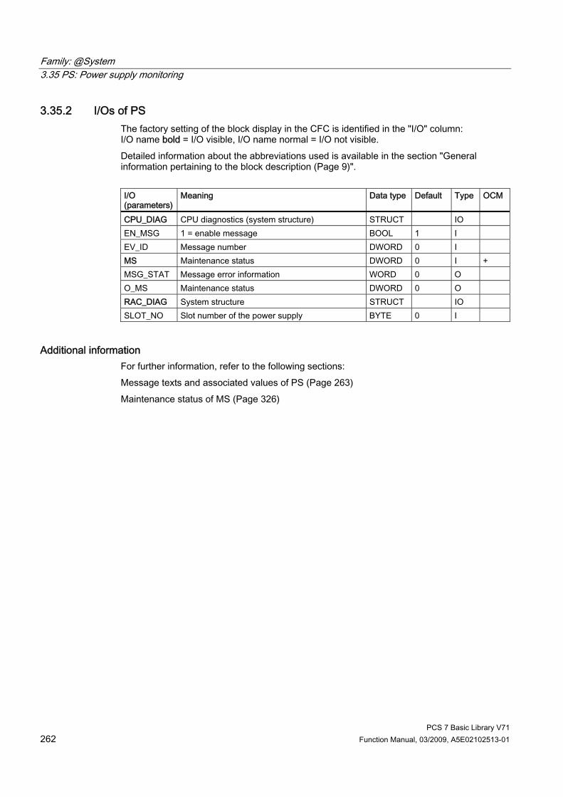
Family: @System 3.35 PS: Power supply monitoring
PCS 7 Basic Library V71 262 Function Manual, 03/2009, A5E02102513-01
3.35.2 I/Os of PS The factory setting of the block display in the CFC is identified in the "I/O" column: I/O name bold = I/O visible, I/O name normal = I/O not visible. Detailed information about the abbreviations used is available in the section "General information pertaining to the block description (Page 9)". I/O (parameters)
Meaning Data type Default
Type OCM
CPU_DIAG CPU diagnostics (system structure) STRUCT IO EN_MSG 1 = enable message BOOL 1 I EV_ID Message number DWORD 0 I MS Maintenance status DWORD 0 I + MSG_STAT Message error information WORD 0 O O_MS Maintenance status DWORD 0 O RAC_DIAG System structure STRUCT IO SLOT_NO Slot number of the power supply BYTE 0 I
Additional information For further information, refer to the following sections: Message texts and associated values of PS (Page 263) Maintenance status of MS (Page 326)

Family: @System 3.35 PS: Power supply monitoring
PCS 7 Basic Library V71 Function Manual, 03/2009, A5E02102513-01 263
3.35.3 Message Texts and Associated Values of PS
Assignment of message text and message class (Page 324) Message No. Default message text Message class 1 @1%d@/ @2%d@/ @3%d@: Backup battery failure M 2 @1%d@/ @2%d@/ @3%d@: Backup voltage failure M 3 @1%d@/ @2%d@/ @3%d@: 24 V power supply failure M 4 Module @1%d@/ @2%d@/ @3%d@: Removed W 5 Module @1%d@/ @2%d@/ @3%d@: wrong or faulty W 6 No message 7 No message 8 No message
Assignment of Associated Values Associated value
Block parameters
1 DP master system number of the rack of the power supply (RAC_DIAG.SUBN_ID) 2 Rack number of the power supply (RAC_DIAG.RACK_NO) 3 Slot number of the power supply (SLOT_NO)
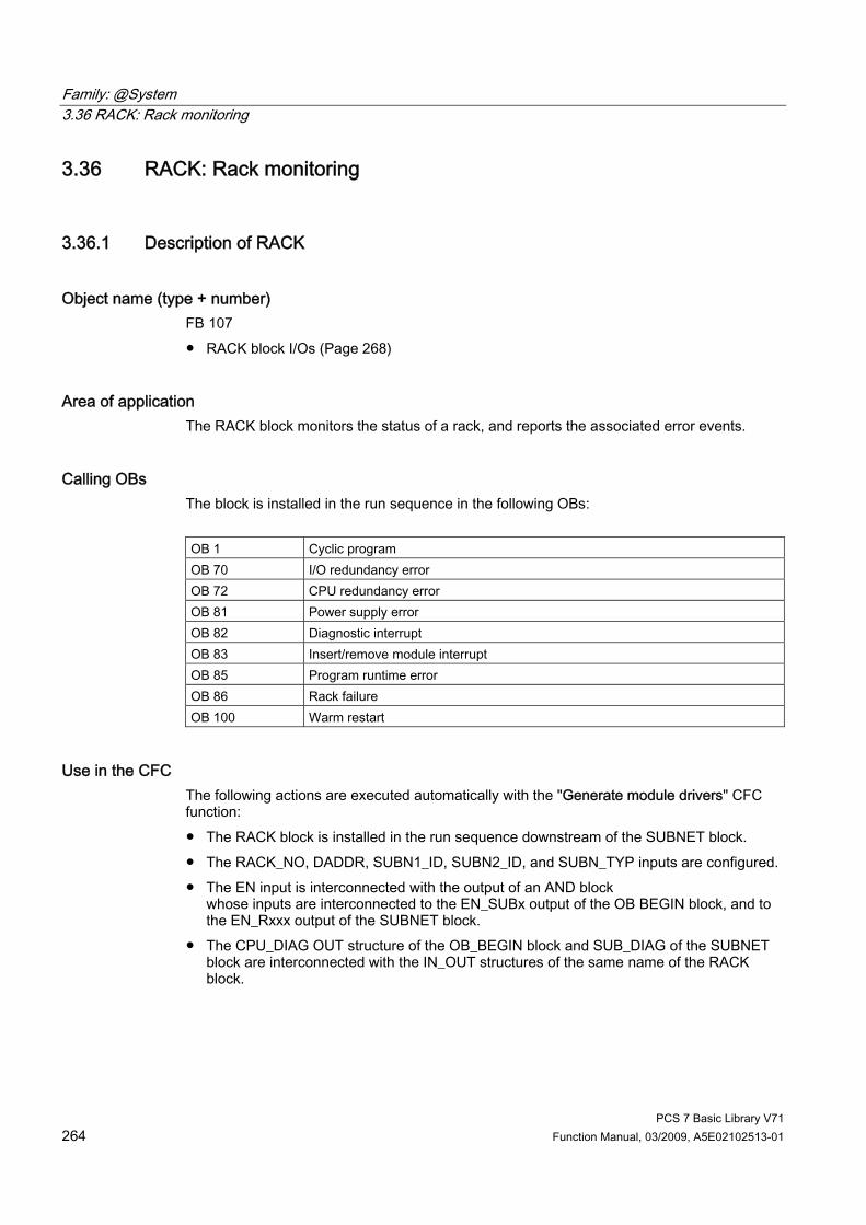
Family: @System 3.36 RACK: Rack monitoring
PCS 7 Basic Library V71 264 Function Manual, 03/2009, A5E02102513-01
3.36 RACK: Rack monitoring
3.36.1 Description of RACK
Object name (type + number) FB 107 ● RACK block I/Os (Page 268)
Area of application The RACK block monitors the status of a rack, and reports the associated error events.
Calling OBs The block is installed in the run sequence in the following OBs: OB 1 Cyclic program OB 70 I/O redundancy error OB 72 CPU redundancy error OB 81 Power supply error OB 82 Diagnostic interrupt OB 83 Insert/remove module interrupt OB 85 Program runtime error OB 86 Rack failure OB 100 Warm restart
Use in the CFC The following actions are executed automatically with the "Generate module drivers" CFC function: ● The RACK block is installed in the run sequence downstream of the SUBNET block. ● The RACK_NO, DADDR, SUBN1_ID, SUBN2_ID, and SUBN_TYP inputs are configured. ● The EN input is interconnected with the output of an AND block
whose inputs are interconnected to the EN_SUBx output of the OB BEGIN block, and to the EN_Rxxx output of the SUBNET block.
● The CPU_DIAG OUT structure of the OB_BEGIN block and SUB_DIAG of the SUBNET block are interconnected with the IN_OUT structures of the same name of the RACK block.
Family: @System 3.36 RACK: Rack monitoring
PCS 7 Basic Library V71 Function Manual, 03/2009, A5E02102513-01 265
Function and method of operation The RACK block generates a process control error message for the OS in the event of redundancy losses and rack/station failures. It also indicates internal errors of the rack/station (SUBN1ERR, SUBN2ERR), and of the preferred channel (SUBN1ACT, SUBN2ACT) if there are active DP slaves at its outputs. The output structure RAC_DIAG contains the geographic address of the rack, and the group error information RACK_ERR. If RACK_ERR = 1, the corresponding rack is not available. The block is installed in the OBs listed above once at each station or local I/O device. The SUBNET block enables the runtime group that contains the RACK block. Start and diagnostic information is read from the CPU_DIAG IN_OUT structure, which is interconnected with the CPU_DIAG structure of the OB_BEGIN block. The RACK block has one enable output for each rack (station) slot. The RACK block generates the number of a corresponding message (see "Message Response") on the basis of the start information of the calling OBs if the current block is affected. The block evaluates error events, and uses the diagnostic address DADDR of the DP slave to determine the currently active preferred channel (SUBN1ACT, SUBN2ACT) of redundant PROFIBUS DP interface circuits. Note: If you want to change the SUBN1_ID (connection to CPU 0) and SUBN2_ID (connection to CPU 1) inputs online, you must set input ACC_ID = TRUE to update the output values.
Redundancy In H systems with distributed I/Os, the RACK block supports redundancy of the DP Master systems. If you want to use this function, you must configure the SUBN1_ID (connection to CPU 0) and SUBN2_ID (connection to CPU 1) inputs of the RACK block with the numbers of the redundant DP master systems. If there is no redundancy, the remaining input must be set to the (default) value 16#FF.
Note With redundant CPU racks, the two RACK blocks inserted in the system chart are only responsible for enabling lower-level block chains. Their maintenance status MS is therefore irrelevant. The "Good" and "Not redundant" state is always shown in the associated faceplate and block icon because the bits 0 to 16 of the MS are always "0" in this case.
Error handling Error handling of the block is limited to evaluation of the error information of ALARM_8P. You will find more information about this in "Error information for output parameter MSG_STAT (Page 322)".

Family: @System 3.36 RACK: Rack monitoring
PCS 7 Basic Library V71 266 Function Manual, 03/2009, A5E02102513-01
Startup characteristics The RACK block initializes ALARM_8P messages. It checks availability of the station and, in H systems, determines the preferred channel of the station. The SUB_DIAG.V1_MODE structure (0 = compatibility mode, 1 = DPV1 mode) is transferred to the RAC_DIAG.V1_MODE structure.
Overload behavior The RACK block counts the OB 86 calls (except in the case of a DP master system failure; see SUBNET block). The counter is reset in OB 1. If more than two OB 86 events occur in succession before the cycle control point (OB 1) is reached, these will be rejected and the message "Station...: Multiple failure" is output. When an OB 86 call is rejected, the rack (station) is registered as having failed.
Time response See "Message Response"
Message functionality After it is called by OB 70, OB 72, OB 85 or OB 86, the block analyzes the status of its assigned CPU, DP master and DP slave. If the rack (station) loses redundancy or fails, the block outputs the corresponding messages by broadcasting an ALARM_8P. The message function can be disabled by setting EN_MSG = FALSE. The block generally reports only the events that were originally generated in the rack that it monitors. Redundancy loss and station failures which are caused by the failure of a DP master or CPU are initially neither signaled nor indicated at the SUBN1ERR and SUBN2ERR outputs. The DELAY input is used to delay the outputting of error messages for an outgoing, higher-priority error. For example, if the RACK block recognizes an outgoing error at an interconnected DP master, it initially assumes that there is a faulty assigned DP slave in the rack it monitors, and sets the corresponding output SUBNxERR. The error status is not reset until the DP slave returns (in this case: OB 86, OB 70). The RACK blocks suppress the potential slave failure states for DELAY seconds so as not to trigger a surge of messages from DP slaves which are not yet synchronized when the master returns. An error message is not output to the OS unless the DP slave has reported its return before this delay time has expired. Note: Do not set the value of DELAY too high, otherwise DP slaves that were removed during the master failure or are defective will be signaled to the OS too late after the DP master returns.

Family: @System 3.36 RACK: Rack monitoring
PCS 7 Basic Library V71 Function Manual, 03/2009, A5E02102513-01 267
The RACK block generates the following messages in the OBs listed below: OB Start event Message OB 1 Cyclic processing Repeat the update of ALARM_8P outputs/messages, if
necessary OB 70 Redundancy loss Station redundancy loss/return OB 81 Power supply error OB 85 Program execution error Station failure, incoming/outgoing OB 86 Rack failure Station failure, incoming/outgoing OB 100 Restart Initialization of ALARM_8P
Operator control and monitoring Note: If you selected the "Enable operator control and monitoring" option in the block object properties in the CFC, the variables transferred to the OS are identified under "I/Os of ..." (OCM column, "+"). Default: Option not activated. If asset management is used in the project and the diagnostic screens have been generated, the faceplate can be called via its block icon. ● Asset management block icons (Page 284) ● Asset management faceplates (Page 286)
Additional information For further information, refer to the following sections: Message texts and associated values of RACK (Page 269) Maintenance status of MS (Page 326)

Family: @System 3.36 RACK: Rack monitoring
PCS 7 Basic Library V71 268 Function Manual, 03/2009, A5E02102513-01
3.36.2 I/Os of RACK The factory setting of the block display in the CFC is identified in the "I/O" column: I/O name bold = I/O visible, I/O name normal = I/O not visible. Detailed information about the abbreviations used is available in the section "General information pertaining to the block description (Page 9)". I/O (parameters)
Meaning Data type Default
Type OCM
ACC_ID 1 = Activate MODE settings BOOL 0 IO CPU_DIAG CPU diagnostics (system structure) STRUCT IO DADDR Diagnostic address of the DP slave INT 0 I DELAY Interrupt delay (s) INT 15 I EN_MSG 1 = enable message BOOL 1 I EN_Mxx 1 = Enable module xx (xx = 00 - 30) BOOL 0 O EV_ID Message number DWORD 0 I MS Maintenance status DWORD 0 I + MSG_STAT Message error status WORD 0 O O_MS Maintenance status DWORD 0 O RAC_DIAG System structure STRUCT O RACK_NO Rack number BYTE 0 I SUB_DIAG OB_Start information STRUCT IO SUBN_TYP 1 = external DP interface BOOL 0 I SUBN1_ID ID of the primary DP master system BYTE 255 I SUBN1ACT 1 = Slave 1 is active BOOL 0 O SUBN1ERR 1 = Error in slave 1 BOOL 0 O SUBN2_ID ID of the redundant DP master system BYTE 255 I SUBN2ACT 1 = Slave 2 is active BOOL 0 O SUBN2ERR 1 = Error in slave 2 BOOL 0 O
Additional information For further information, refer to the following sections: Message texts and associated values of RACK (Page 269) Maintenance status of MS (Page 326)
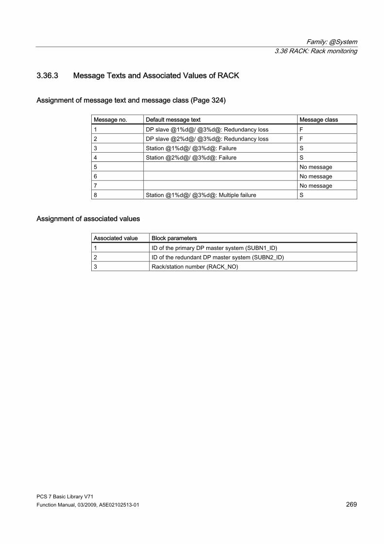
Family: @System 3.36 RACK: Rack monitoring
PCS 7 Basic Library V71 Function Manual, 03/2009, A5E02102513-01 269
3.36.3 Message Texts and Associated Values of RACK
Assignment of message text and message class (Page 324) Message no. Default message text Message class 1 DP slave @1%d@/ @3%d@: Redundancy loss F 2 DP slave @2%d@/ @3%d@: Redundancy loss F 3 Station @1%d@/ @3%d@: Failure S 4 Station @2%d@/ @3%d@: Failure S 5 No message 6 No message 7 No message 8 Station @1%d@/ @3%d@: Multiple failure S
Assignment of associated values Associated value Block parameters 1 ID of the primary DP master system (SUBN1_ID) 2 ID of the redundant DP master system (SUBN2_ID) 3 Rack/station number (RACK_NO)

Family: @System 3.37 RED_F: Status processing of redundant F modules
PCS 7 Basic Library V71 270 Function Manual, 03/2009, A5E02102513-01
3.37 RED_F: Status processing of redundant F modules
3.37.1 Description of RED_F
Object name (type + number) FC 289 ● RED_F block I/Os (Page 272)
Area of application The RED_F block is used to set up redundant F modules in safety mode.
Calling OBs The block must be installed in the same OB before the OR block. It is also installed in OB 100.
Use in CFC The following actions are executed automatically with the "Generate module drivers" CFC function: ● The RED_F block is installed before the OR block in its OB. ● MODE1_xx inputs are interconnected with the OMODE_xx outputs of the MOD_x block in
the primary module. ● MODE2_xx inputs are interconnected with the OMODE_xx outputs of the MOD_x block in
the redundant module. ● The RACKF1 input is interconnected with the QRACKF output of the MOD_x block of the
primary module. ● The RACKF2 input is interconnected with the QRACKF output of the MOD_x block of the
redundant module. ● The MS1 input is interconnected with the O_MS output of the MOD_x block of the primary
module. ● The MS2 input is interconnected with the O_MS output of the MOD_x block of the
redundant module. ● The ACTIV_H and ACTIV_L outputs are interconnected with the inputs with the same
name in the OR block. ● The CH_INF_H and CH_INF_L outputs are interconnected with the inputs with the same
name in the OR block. ● The RETURN_VAL output is interconnected with the RED_STAT input of the OR block. ● The MODUL_STATUS_WORD output is interconnected with the MOD_STAT input of the
OR block.

Family: @System 3.37 RED_F: Status processing of redundant F modules
PCS 7 Basic Library V71 Function Manual, 03/2009, A5E02102513-01 271
Function and operating principle The RED_F block processes the status of all channels cyclically based on the outputs OMODE_xx or the MOD_x blocks and then forms the information on redundancy of the OR blocks.
Addressing Not available
Error handling Not available
Startup characteristics Not available
Time response Not available
Message response Not available
Operating and monitoring The block has no faceplate.

Family: @System 3.37 RED_F: Status processing of redundant F modules
PCS 7 Basic Library V71 272 Function Manual, 03/2009, A5E02102513-01
3.37.2 I/Os of RED_F The factory setting of the block display in CFC is identified in the "I/O" column: I/O name in bold characters = I/O is visible; I/O name in standard characters = I/O is hidden. You will find explanations of and information about the abbreviations used in "General information about the block description (Page 9)".
I/O (parameters)
Meaning Data type Default Type
ACTIV_H 1 = module with more significant address is active BOOL 0 O ACTIV_L 1 = module with less significant address is active BOOL 0 O CH_INF_H 1 = channel with more significant address is active DWORD 0 O CH_INF_L 1 = channel with less significant address is active DWORD 0 O MODE1_xx Channel mode (xx = 00 – 31)
on the primary module DWORD 0 I
MODE2_xx Channel mode (xx = 00 – 31) on the redundant module
DWORD 0 I
MODUL_STATUS_WORD Status information WORD 0 O MS1 Maintenance status (MS) 1 BOOL 0 I MS2 Maintenance status (MS) 2 BOOL 0 I RACKF1 1 = error rack 1 BOOL 0 I RACKF2 1 = error rack 2 BOOL 0 I RETURN_ VAL Error information INT 0 O
Additional information You will find more information in: Maintenance status of MS (Page 326)
Family: @System 3.38 SUBNET: DP master system monitoring
PCS 7 Basic Library V71 Function Manual, 03/2009, A5E02102513-01 273
3.38 SUBNET: DP master system monitoring
3.38.1 Description of SUBNET
Object name (type + number) FB 106 ● SUBNET block I/Os (Page 277)
Area of application The SUBNET block is used to shorten acyclic OB processing times. Only the blocks that are actually affected can be called for an acyclic event.
Calling OBs The SUBNET block must be installed in the run sequence in the following OBs: OB 1 Cyclic program OB 55 Status interrupt (only if a DP/PA slave is required) OB 56 Update interrupt (only if a DP/PA slave is required) OB 57 Vendor-specific alarm (only if a DP/PA slave is required) OB 70 I/O redundancy error OB 72 CPU redundancy error OB 81 Power supply error OB 82 Diagnostic interrupt OB 83 Insert/remove module interrupt OB 85 Program runtime error OB 86 Rack failure OB 100 Warm restart

Family: @System 3.38 SUBNET: DP master system monitoring
PCS 7 Basic Library V71 274 Function Manual, 03/2009, A5E02102513-01
Use in the CFC The following actions are executed automatically with the "Generate module drivers" CFC function: ● Runtime groups with driver/system blocks are created and organized by rack. ● The SUBN1_ID, SUBN2_ID and SUBN_TYP inputs are configured. ● The EN_Rxxx outputs are interconnected with the relevant blocks (e.g., RACK). ● The IN_OUT structure CPU_DIAG is interconnected with the OUT structure of the
OB_BEGIN block. ● The IN_OUT structure SZL_71 is interconnected with the OUT structure of the
OB_BEGIN block. ● The OUT structure SUB_DIAG is interconnected with the IN_OUT structures of the
affected blocks (such as RACK).
Function and method of operation The SUBNET block monitors a DP master system, and enables the blocks (such as RACK) for processing the connected DP slaves (such as ET 200M). Corresponding messages are generated, and the SUBN1ERR and SUBN2ERR outputs are set if a DP master system fails or loses redundancy. The SUB_DIAG output structure contains the geographic address of the DP Master system (and of DP Master system 2 in H systems), as well as the group error information SUBN0_ERR (for DP master system 1) and SUBN1_ERR (for DP master system 2). If SUBN0_ERR = 1 or SUBN1_ERR = 1, the corresponding DP master system is not available. The SUBNET block is installed in each connected DP master system or in the OBs listed above once for the local I/O devices. It is enabled by OB_BEGIN. Start and diagnostic information is read from the CPU_DIAG structure. It is interconnected with the CPU_DIAG structure of the OB_BEGIN. The SUBNET block is assigned one enable output for each connectable rack or DP Master system (for each expansion rack for central I/Os). It uses the start information of the calling OB to determine whether the reported event occurred at its DP master (or at the central I/O), and then sets the output for the affected rack or DP master system (EN_Rxxx). If redundant DP master systems are used (for H CPUs only), a rack (such as ET 200M) is connected to the two DP masters, and is assigned the same station number at both. The SUBNET block has two input parameters (SUBNx_ID), and the type identifier SUBN_TYP for this function. If the integrated interface of the CPU module is the DP master, SUBN_TYP = FALSE, otherwise SUBN_TYP = TRUE. The MASTER_0 and MASTER_1 outputs indicate which CPU is currently the master. If a DP master fails, the system sets all EN_Rxxx = TRUE, and reports a redundancy loss or failure. The return of redundancy or the DP master is reported when a failed DP slave has reestablished the connection. The status of the DP master system, the set SUBNx_ID and type identifier are saved in the output structure SUB_DIAG. If a "power supply error" (OB 81) event occurs, the SUBNET block will enable only those RACK blocks that are expansion racks, which is indicated by SUBNx_ID = 0. Note: If you want to change the SUBN1_ID (connection to CPU 0) and SUBN2_ID (connection to CPU 1) inputs online, you must set input ACC_ID = TRUE to update the output values.
Family: @System 3.38 SUBNET: DP master system monitoring
PCS 7 Basic Library V71 Function Manual, 03/2009, A5E02102513-01 275
Redundancy The SUBNET block supports redundancy of DP master systems of the 414-H/417-H CPU if distributed I/Os are used. To use this function, you must configure the SUBN1_ID (connection to CPU 0) and SUBN2_ID (connection to CPU 1) inputs with the numbers of the redundant DP master systems. If there is no redundancy, the remaining input must be assigned the value 16#FF (default).
Error handling The error handling for the block is limited to evaluation of the error information from ALARM_8P. You will find further information about error handling in "Error information for output parameter MSG_STAT (Page 322)".
Startup/initial startup behavior The SUBNET block initializes the messages of ALARM_8P. The operating mode of the DP Master system is checked, and entered in the SUB_DIAG.V1_MODE structure with SSL 0X90H (0 = compatibility mode, 1 = DPV1 mode). If DPV1 mode is active, the CPU_DIAG.MODE_V1 structure is also set to TRUE.
Overload behavior The SUBNET block counts the OB 86 calls (failures only). The counter is reset in OB1. If more than two OB 86 failure events occur in succession before the cycle control point (OB1) is reached, these are rejected and a message "Failure OB 86 DP master system:x" is output. If an OB 86 call is rejected, the DP master system is registered as having failed.
Time response Not available
Message functionality After being called by an OB 86, OB 70 and OB 72, the block analyzes the status of its assigned DP master system, and generates the relevant messages for redundancy loss or DP master system failure by broadcasting an ALARM_8P. The message function can be disabled by setting EN_MSG = FALSE. The SUBNET block generally reports only events triggered in the DP master system it monitors. Exception: If a CPU fails in the H system, the following messages are generated: ● in a non-redundant DP master system: “DP master failure” message ● in a redundant DP master system: “DP master redundancy loss” message
Family: @System 3.38 SUBNET: DP master system monitoring
PCS 7 Basic Library V71 276 Function Manual, 03/2009, A5E02102513-01
Operator control and monitoring Note: If you selected the "Enable operator control and monitoring" option in the block object properties in the CFC, the variables transferred to the OS are identified under "I/Os of ..." (OCM column, "+"). Default: Option not activated. If asset management is used in the project and the diagnostic screens have been generated, the faceplate can be called via its block icon. ● Asset management block icons (Page 284) ● Asset management faceplates (Page 286)
Additional information For further information, refer to the following sections: Message Texts and associated values of SUBNET (Page 278) Maintenance status of MS (Page 326)
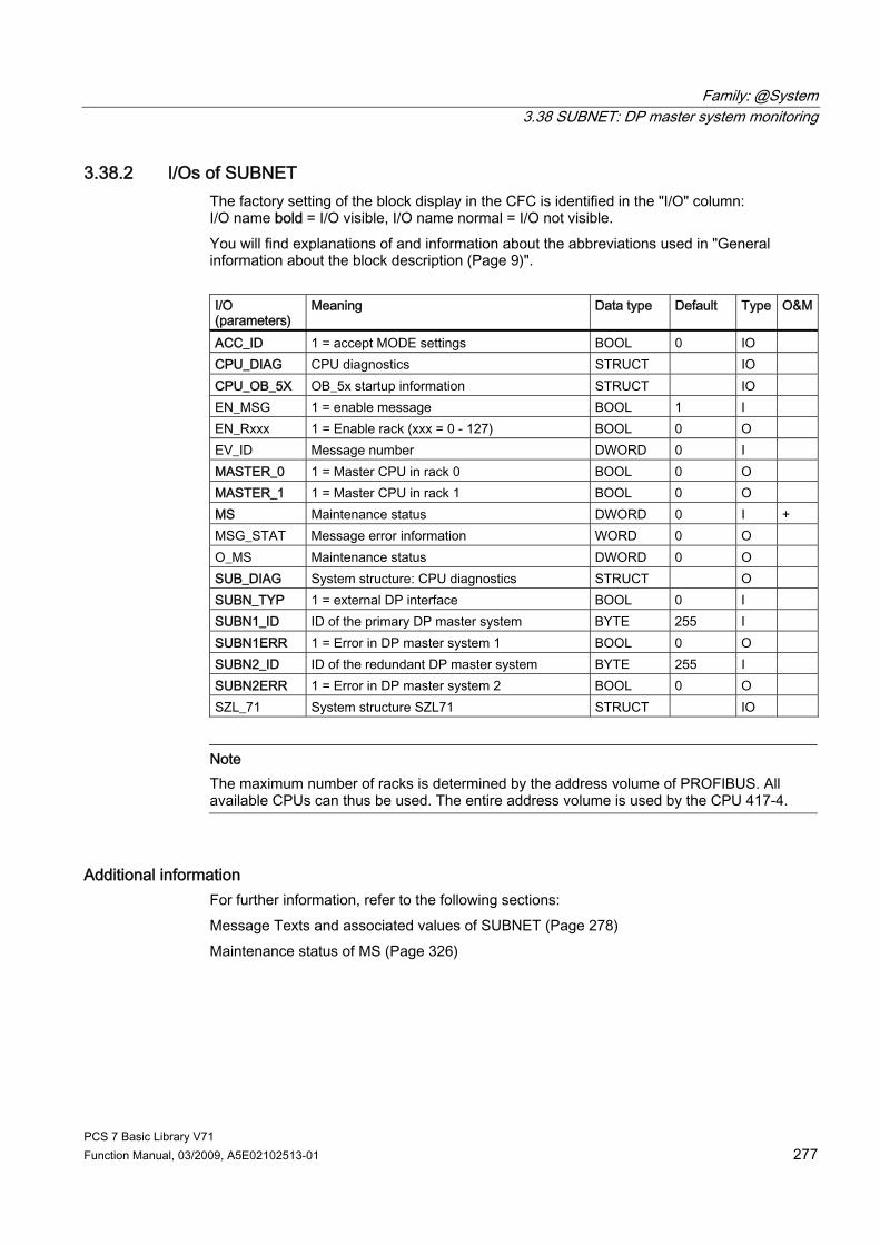
Family: @System 3.38 SUBNET: DP master system monitoring
PCS 7 Basic Library V71 Function Manual, 03/2009, A5E02102513-01 277
3.38.2 I/Os of SUBNET The factory setting of the block display in the CFC is identified in the "I/O" column: I/O name bold = I/O visible, I/O name normal = I/O not visible. You will find explanations of and information about the abbreviations used in "General information about the block description (Page 9)". I/O (parameters)
Meaning Data type Default Type O&M
ACC_ID 1 = accept MODE settings BOOL 0 IO CPU_DIAG CPU diagnostics STRUCT IO CPU_OB_5X OB_5x startup information STRUCT IO EN_MSG 1 = enable message BOOL 1 I EN_Rxxx 1 = Enable rack (xxx = 0 - 127) BOOL 0 O EV_ID Message number DWORD 0 I MASTER_0 1 = Master CPU in rack 0 BOOL 0 O MASTER_1 1 = Master CPU in rack 1 BOOL 0 O MS Maintenance status DWORD 0 I + MSG_STAT Message error information WORD 0 O O_MS Maintenance status DWORD 0 O SUB_DIAG System structure: CPU diagnostics STRUCT O SUBN_TYP 1 = external DP interface BOOL 0 I SUBN1_ID ID of the primary DP master system BYTE 255 I SUBN1ERR 1 = Error in DP master system 1 BOOL 0 O SUBN2_ID ID of the redundant DP master system BYTE 255 I SUBN2ERR 1 = Error in DP master system 2 BOOL 0 O SZL_71 System structure SZL71 STRUCT IO
Note The maximum number of racks is determined by the address volume of PROFIBUS. All available CPUs can thus be used. The entire address volume is used by the CPU 417-4.
Additional information For further information, refer to the following sections: Message Texts and associated values of SUBNET (Page 278) Maintenance status of MS (Page 326)

Family: @System 3.38 SUBNET: DP master system monitoring
PCS 7 Basic Library V71 278 Function Manual, 03/2009, A5E02102513-01
3.38.3 Message Texts and Associated Values of SUBNET
Assignment of message text and message class (Page 324) Message no. Default message text Message class 1 DP master @1%d@: Redundancy loss F 2 DP master @2%d@: Redundancy loss F 3 DP master @1%d@: Failure S 4 DP master @2%d@: Failure S 5 DP master @2%d@: Multiple failure S 6 CPU loss of redundancy in rack @4%d@ F
Assignment of associated values Associated value Block parameters 1 ID of the primary DP master system (SUBN1_ID) 2 ID of the redundant DP master system (SUBN2_ID) 3 Multiple failure, ID of DP master system

PCS 7 Basic Library V71 Function Manual, 03/2009, A5E02102513-01 279
Internal block 44.1 ChkREAL: Internal Block
Object name (type + number) FC260 This block is a system block and is only used internally. There is therefore no help available for it.
4.2 QC_CHNG: Internal block
Object name (type + number) FB 135 This block is a system block and is only used internally. There is therefore no help available for it.

Internal block 4.2 QC_CHNG: Internal block
PCS 7 Basic Library V71 280 Function Manual, 03/2009, A5E02102513-01
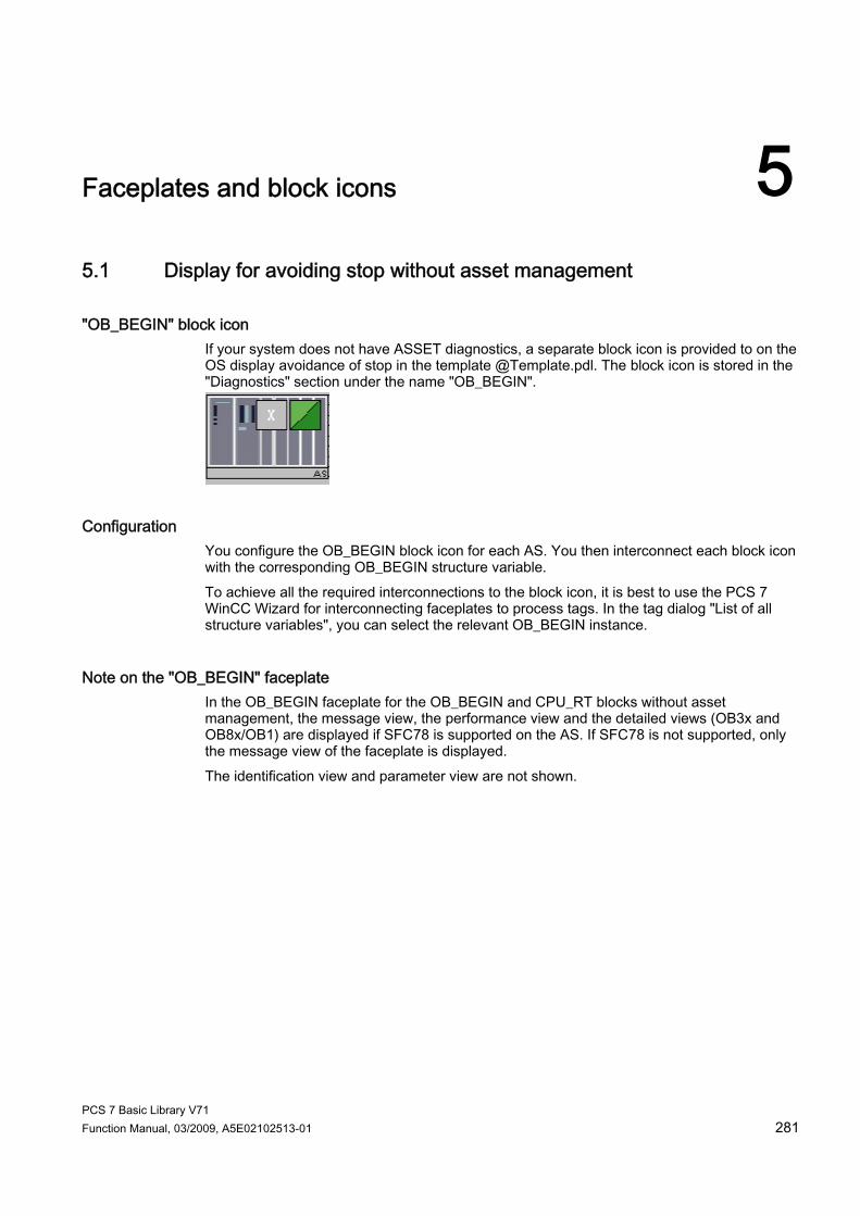
PCS 7 Basic Library V71 Function Manual, 03/2009, A5E02102513-01 281
Faceplates and block icons 55.1 Display for avoiding stop without asset management
"OB_BEGIN" block icon If your system does not have ASSET diagnostics, a separate block icon is provided to on the OS display avoidance of stop in the template @Template.pdl. The block icon is stored in the "Diagnostics" section under the name "OB_BEGIN".
Configuration You configure the OB_BEGIN block icon for each AS. You then interconnect each block icon with the corresponding OB_BEGIN structure variable. To achieve all the required interconnections to the block icon, it is best to use the PCS 7 WinCC Wizard for interconnecting faceplates to process tags. In the tag dialog "List of all structure variables", you can select the relevant OB_BEGIN instance.
Note on the "OB_BEGIN" faceplate In the OB_BEGIN faceplate for the OB_BEGIN and CPU_RT blocks without asset management, the message view, the performance view and the detailed views (OB3x and OB8x/OB1) are displayed if SFC78 is supported on the AS. If SFC78 is not supported, only the message view of the faceplate is displayed. The identification view and parameter view are not shown.
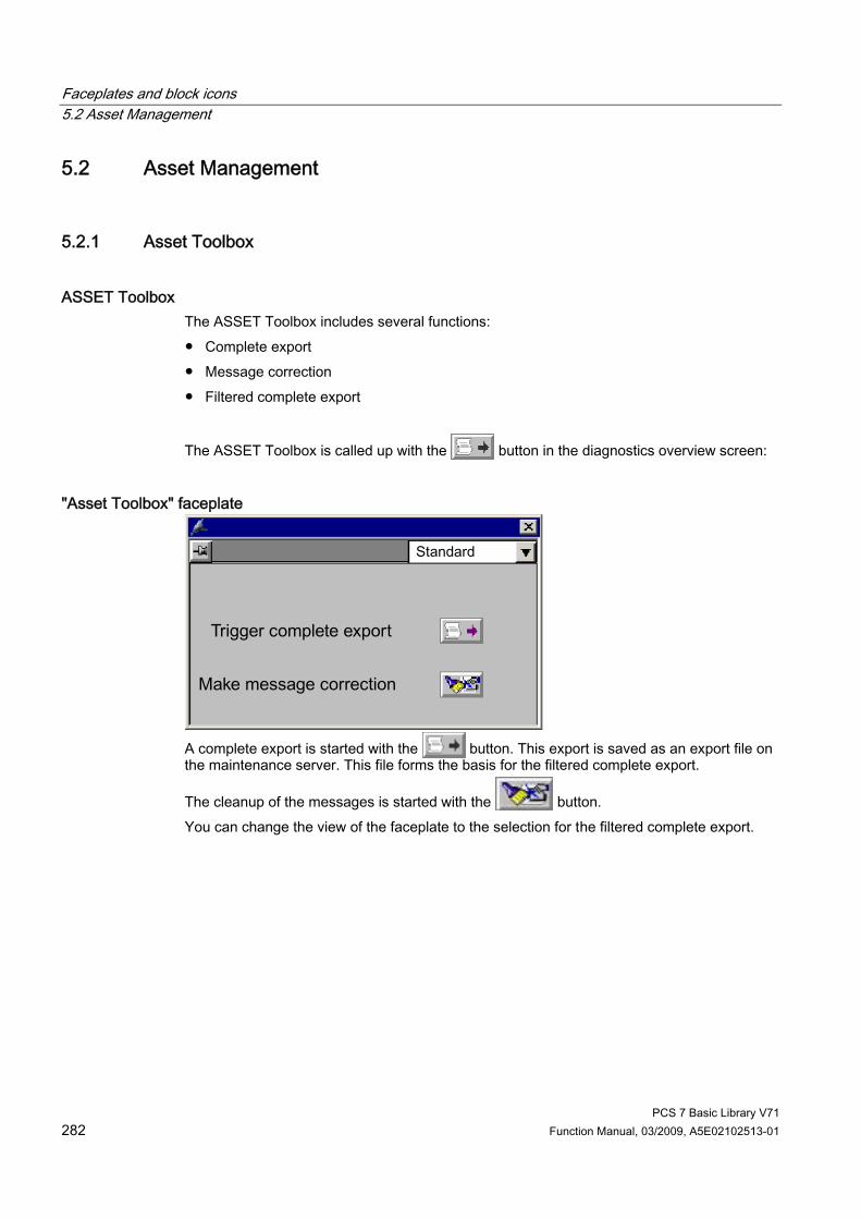
Faceplates and block icons 5.2 Asset Management
PCS 7 Basic Library V71 282 Function Manual, 03/2009, A5E02102513-01
5.2 Asset Management
5.2.1 Asset Toolbox
ASSET Toolbox The ASSET Toolbox includes several functions: ● Complete export ● Message correction ● Filtered complete export
The ASSET Toolbox is called up with the button in the diagnostics overview screen:
"Asset Toolbox" faceplate
A complete export is started with the button. This export is saved as an export file on the maintenance server. This file forms the basis for the filtered complete export.
The cleanup of the messages is started with the button. You can change the view of the faceplate to the selection for the filtered complete export.

Faceplates and block icons 5.2 Asset Management
PCS 7 Basic Library V71 Function Manual, 03/2009, A5E02102513-01 283
"Asset Tools" faceplate
Here, you can set individual filters for device status, OS operation, status and free text. Select the check boxes to enable or disable the individual filter criteria. You can enable all the check boxes with the "Select All" button. In the lower "Text" area, there are two text filters available. In the left-hand text boxes, you can select the available identification data from a drop-down list box. You can enter any text you require in the right-hand text boxes. You can also set "AND", "OR" or "NOT" options for these text boxes. Select the "Show data" button to display the required view in the form of a table in the "Result" faceplate.

Faceplates and block icons 5.2 Asset Management
PCS 7 Basic Library V71 284 Function Manual, 03/2009, A5E02102513-01
5.2.2 Block Icons: Asset Management
Block Icons Supported by the System The block icons for asset management supported by the system are contained in the "@@maintenancetypicals.pdl" picture. This file is located under ..\SIEMENS\WinCC\options\pdl\faceplatedesigner_v6" and is copied from the installation directory to the project directory under ..\wincproj\<os-name>\GraCS when a PCS 7 project is generated or when the OS project editor is run. Icons in the Block Icon
Meaning Local operation
Diagnostic block icon with the self-diagnosis icon (top right) and the group display with the status of the lower-level hierarchy (bottom right)

Faceplates and block icons 5.2 Asset Management
PCS 7 Basic Library V71 Function Manual, 03/2009, A5E02102513-01 285
Icons in the Block Icon
Meaning Local operation
"Self-diagnosis (maintenance state)" icon of the component Depending on the maintenance status, the icons shown in the right-hand column can be displayed within the component. This only applies to non-redundant components. Regardless of which icon is displayed, the icon is used to open the faceplate of the component. The table shown under "Status display for redundant components [Asset]" is applicable for redundant components.
Maintenance alarm
Maintenance request
Maintenance required
Component good
Local operation
At least one process value is being simulated
Out of service
Component passivated
Unchecked/unknown
Configuration changed
Maintenance in progress
Maintenance job requested, alarm priority
Maintenance job requested, demand priority
Maintenance job requested, request priority
Group display for same-level components The small square (group display) at the bottom right indicates the following: An alarm has not yet been acknowledged. The alarm can also have already completed. Alarms remain flashing until they are acknowledged. If the alarm is still pending, the icon stops flashing. If the alarm is no longer pending, the icon disappears.
Possible icons in the group display Maintenance alarm Maintenance request Maintenance required Good

Faceplates and block icons 5.2 Asset Management
PCS 7 Basic Library V71 286 Function Manual, 03/2009, A5E02102513-01
Icons in the Block Icon
Meaning Local operation
Group display for lower-level hierarchy A maintenance alarm, for example, is pending within the nested diagnostic pictures. Only the highest-priority class is displayed. Regardless of which icon is shown in the group display, the left-hand icon is used to open the lower-level hierarchy.
Possible icons in the group display Maintenance alarm Maintenance request Maintenance required Good
DeviceIcon If HW Config contains a bit map, a bit map displaying the device icon is shown in the "DeviceIcon" property.
5.2.3 Faceplates: Asset Management
Overview Global representations and views of asset faceplates (Page 305) Maintenance View [Asset] (Page 297) Message View [Asset] (Page 299) Ident View [Asset] (Page 300) Individual views of the PDM faceplate [Asset] (Page 287) Individual views of the IPC faceplate [Asset] (Page 290) Views of the OB_BEGIN faceplate [Asset] (Page 292)
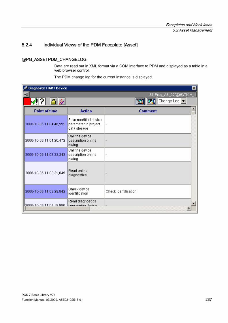
Faceplates and block icons 5.2 Asset Management
PCS 7 Basic Library V71 Function Manual, 03/2009, A5E02102513-01 287
5.2.4 Individual Views of the PDM Faceplate [Asset]
@PG_ASSETPDM_CHANGELOG Data are read out in XML format via a COM interface to PDM and displayed as a table in a web browser control. The PDM change log for the current instance is displayed.

Faceplates and block icons 5.2 Asset Management
PCS 7 Basic Library V71 288 Function Manual, 03/2009, A5E02102513-01
@PG_ASSETPDM_Parameters The data is read to PDM in XML format via a COM interface, and displayed in table format in a web browser control. The device parameters saved in PDM for the current instance are displayed.
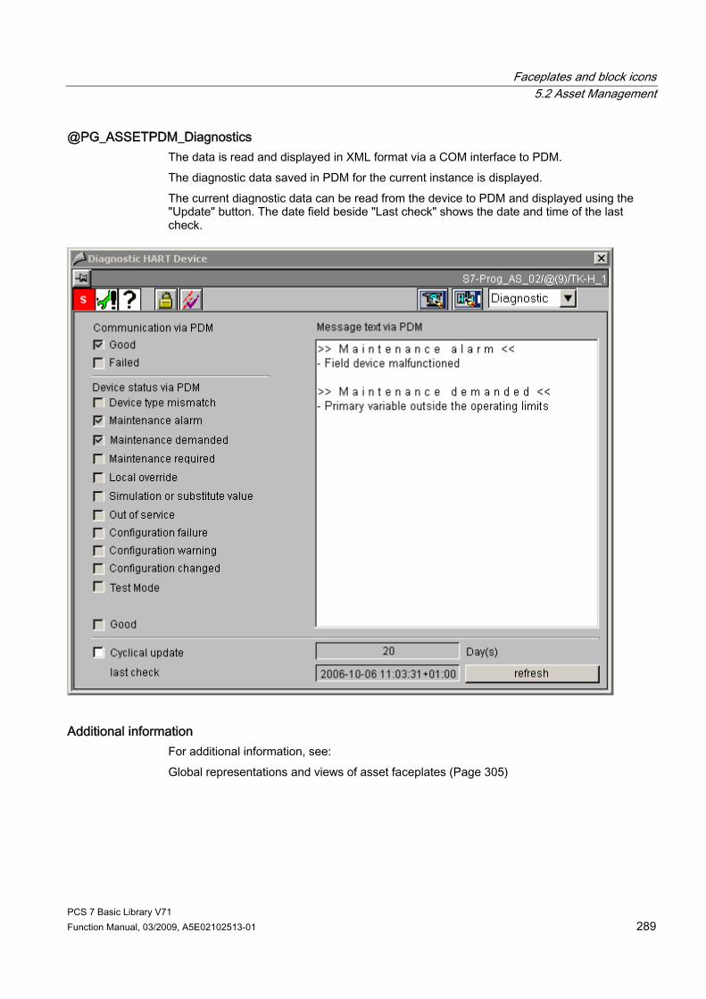
Faceplates and block icons 5.2 Asset Management
PCS 7 Basic Library V71 Function Manual, 03/2009, A5E02102513-01 289
@PG_ASSETPDM_Diagnostics The data is read and displayed in XML format via a COM interface to PDM. The diagnostic data saved in PDM for the current instance is displayed. The current diagnostic data can be read from the device to PDM and displayed using the "Update" button. The date field beside "Last check" shows the date and time of the last check.
Additional information For additional information, see: Global representations and views of asset faceplates (Page 305)

Faceplates and block icons 5.2 Asset Management
PCS 7 Basic Library V71 290 Function Manual, 03/2009, A5E02102513-01
5.2.5 Individual Views of the IPC Faceplate [Asset]
Views With the IPC faceplate, the data of the views "Monitoring1", "Monitoring2", "Monitoring3" of variables is read from the data manager. These variables are created using the "Export variables for WinCC" function in the OPC server properties.
@PG_ASSETIPC_Monitoring1
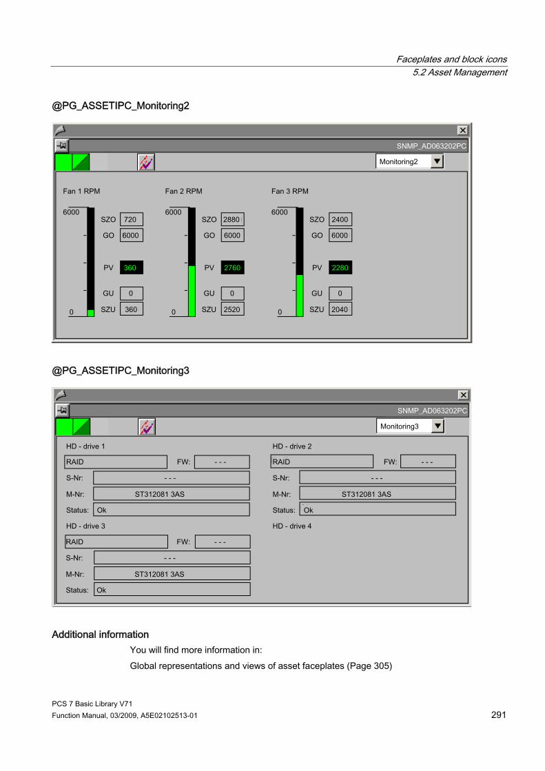
Faceplates and block icons 5.2 Asset Management
PCS 7 Basic Library V71 Function Manual, 03/2009, A5E02102513-01 291
@PG_ASSETIPC_Monitoring2
@PG_ASSETIPC_Monitoring3
Additional information You will find more information in: Global representations and views of asset faceplates (Page 305)

Faceplates and block icons 5.2 Asset Management
PCS 7 Basic Library V71 292 Function Manual, 03/2009, A5E02102513-01
5.2.6 Views of the OB_BEGIN Faceplate [Asset]
Views The faceplate has 7 views: ● Maintenance view (Page 297) ● Message view (Page 299) ● Ident view (Page 300) ● Performance View (Overview) ● OB3x View (Detailed View) ● OB8x/OB1 View (Detailed View) ● Parameter view
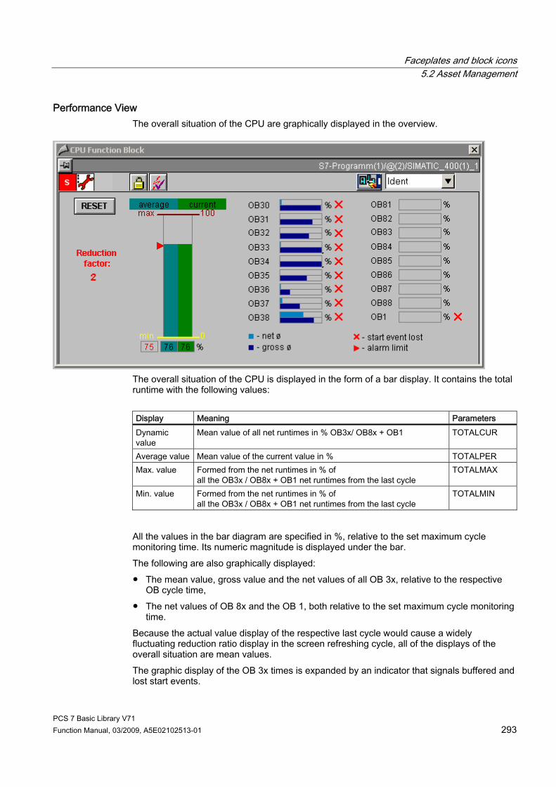
Faceplates and block icons 5.2 Asset Management
PCS 7 Basic Library V71 Function Manual, 03/2009, A5E02102513-01 293
Performance View The overall situation of the CPU are graphically displayed in the overview.
The overall situation of the CPU is displayed in the form of a bar display. It contains the total runtime with the following values: Display Meaning Parameters Dynamic value
Mean value of all net runtimes in % OB3x/ OB8x + OB1 TOTALCUR
Average value Mean value of the current value in % TOTALPER Max. value Formed from the net runtimes in % of
all the OB3x / OB8x + OB1 net runtimes from the last cycle TOTALMAX
Min. value Formed from the net runtimes in % of all the OB3x / OB8x + OB1 net runtimes from the last cycle
TOTALMIN
All the values in the bar diagram are specified in %, relative to the set maximum cycle monitoring time. Its numeric magnitude is displayed under the bar. The following are also graphically displayed: ● The mean value, gross value and the net values of all OB 3x, relative to the respective
OB cycle time, ● The net values of OB 8x and the OB 1, both relative to the set maximum cycle monitoring
time. Because the actual value display of the respective last cycle would cause a widely fluctuating reduction ratio display in the screen refreshing cycle, all of the displays of the overall situation are mean values. The graphic display of the OB 3x times is expanded by an indicator that signals buffered and lost start events.
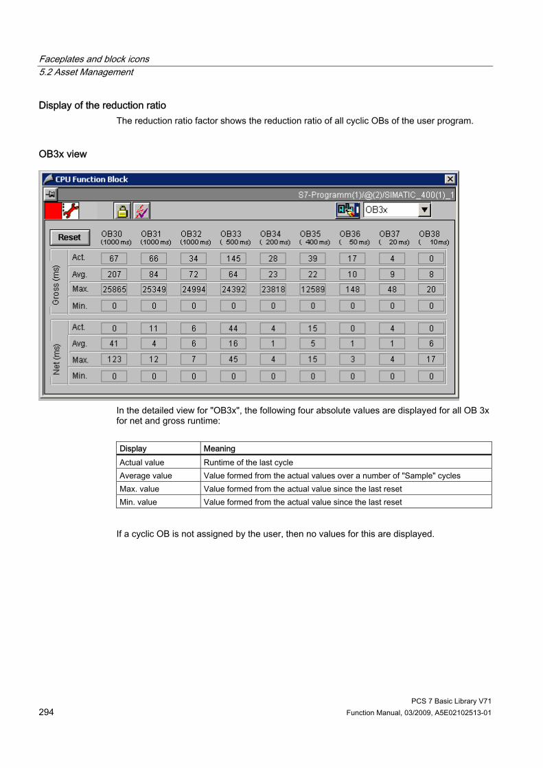
Faceplates and block icons 5.2 Asset Management
PCS 7 Basic Library V71 294 Function Manual, 03/2009, A5E02102513-01
Display of the reduction ratio The reduction ratio factor shows the reduction ratio of all cyclic OBs of the user program.
OB3x view
In the detailed view for "OB3x", the following four absolute values are displayed for all OB 3x for net and gross runtime: Display Meaning Actual value Runtime of the last cycle Average value Value formed from the actual values over a number of "Sample" cycles Max. value Value formed from the actual value since the last reset Min. value Value formed from the actual value since the last reset
If a cyclic OB is not assigned by the user, then no values for this are displayed.

Faceplates and block icons 5.2 Asset Management
PCS 7 Basic Library V71 Function Manual, 03/2009, A5E02102513-01 295
OB8x/OB1 view
In the detailed view for "OB8x OB1", the four absolute values for the net runtime are displayed for all of OB 8x and for OB 1: Display Meaning Actual value Runtime of the last cycle Average value Value formed from the actual values over a number of "Sample" cycles Max. value Value formed from the actual value since the last reset Min. value Value formed from the actual value since the last reset
Note: The values displayed in this view are net values; the values displayed in HW Config are gross values.

Faceplates and block icons 5.2 Asset Management
PCS 7 Basic Library V71 296 Function Manual, 03/2009, A5E02102513-01
Parameter view
In this view, you can select the OBs on the left to which a reduction ratio will apply if there is overload. On the right-hand side, you enter the parameter values that apply when avoiding the CPU changing to STOP and keeping the AS operable. If SFC 78 is not supported in the AS, some information will not be displayed in the view. This involves the following: ● Alarm limit capacity ● Cancel reduction for ● Hysteresis alarm limit ● Calculation of CPU load (display) ● Calculation of CPU load (internal)
Additional information You will find more information in: Global representations and views of asset faceplates (Page 305)
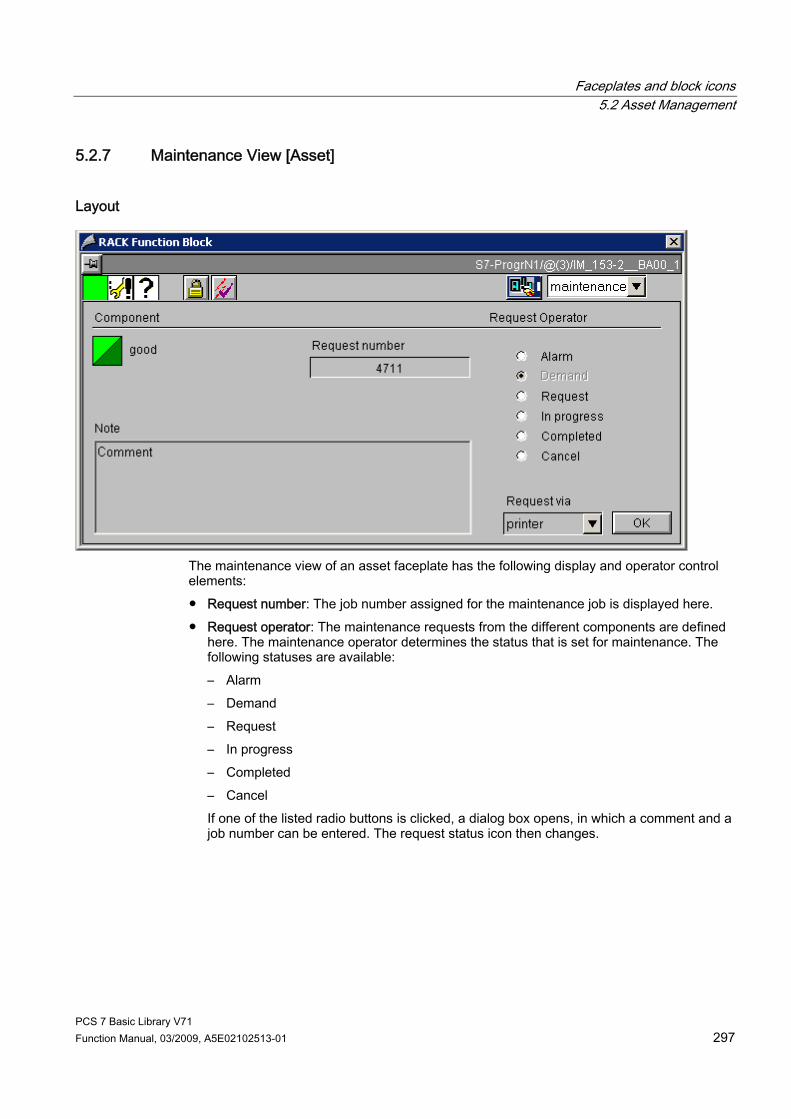
Faceplates and block icons 5.2 Asset Management
PCS 7 Basic Library V71 Function Manual, 03/2009, A5E02102513-01 297
5.2.7 Maintenance View [Asset]
Layout
The maintenance view of an asset faceplate has the following display and operator control elements: ● Request number: The job number assigned for the maintenance job is displayed here. ● Request operator: The maintenance requests from the different components are defined
here. The maintenance operator determines the status that is set for maintenance. The following statuses are available: – Alarm – Demand – Request – In progress – Completed – Cancel If one of the listed radio buttons is clicked, a dialog box opens, in which a comment and a job number can be entered. The request status icon then changes.
Faceplates and block icons 5.2 Asset Management
PCS 7 Basic Library V71 298 Function Manual, 03/2009, A5E02102513-01
● Note: The comments entered for the maintenance job are displayed here. ● Request via: Currently, only "Printer" or "Single export" are possible. Printing a print
report for the selected faceplate.
Note A second print job may not be initiated until the previous job is complete.
Additional information You will find more information in: Global representations and views of asset faceplates (Page 305)
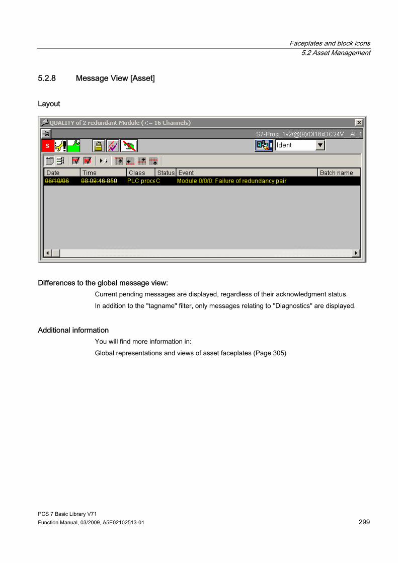
Faceplates and block icons 5.2 Asset Management
PCS 7 Basic Library V71 Function Manual, 03/2009, A5E02102513-01 299
5.2.8 Message View [Asset]
Layout
Differences to the global message view: Current pending messages are displayed, regardless of their acknowledgment status. In addition to the "tagname" filter, only messages relating to "Diagnostics" are displayed.
Additional information You will find more information in: Global representations and views of asset faceplates (Page 305)

Faceplates and block icons 5.2 Asset Management
PCS 7 Basic Library V71 300 Function Manual, 03/2009, A5E02102513-01
5.2.9 Ident View [Asset]
@PG_ASSETAS_Ident
The layout of the Ident page is the same for all faceplates; only the dynamic sampling of the ident data is different. Exception: For devices containing a Web server, a button is available to call a viewer that displays the HTML pages on the devices.
This button is displayed in the overview row of the faceplate if ● The device was configured for SNMP (OSM, ESM and SCALANCE) ● The property "Web-compliant" is stored in the block icon. This button is used in the OSM faceplate. The button is also displayed when the network components are unreachable for certain reasons. You can update the "Last update" box with the "Update" button. Note that with the MS Windows 2003 Server operating system, the IP addresses of the network components to be reached must be included in the "Trusted sites" security settings.
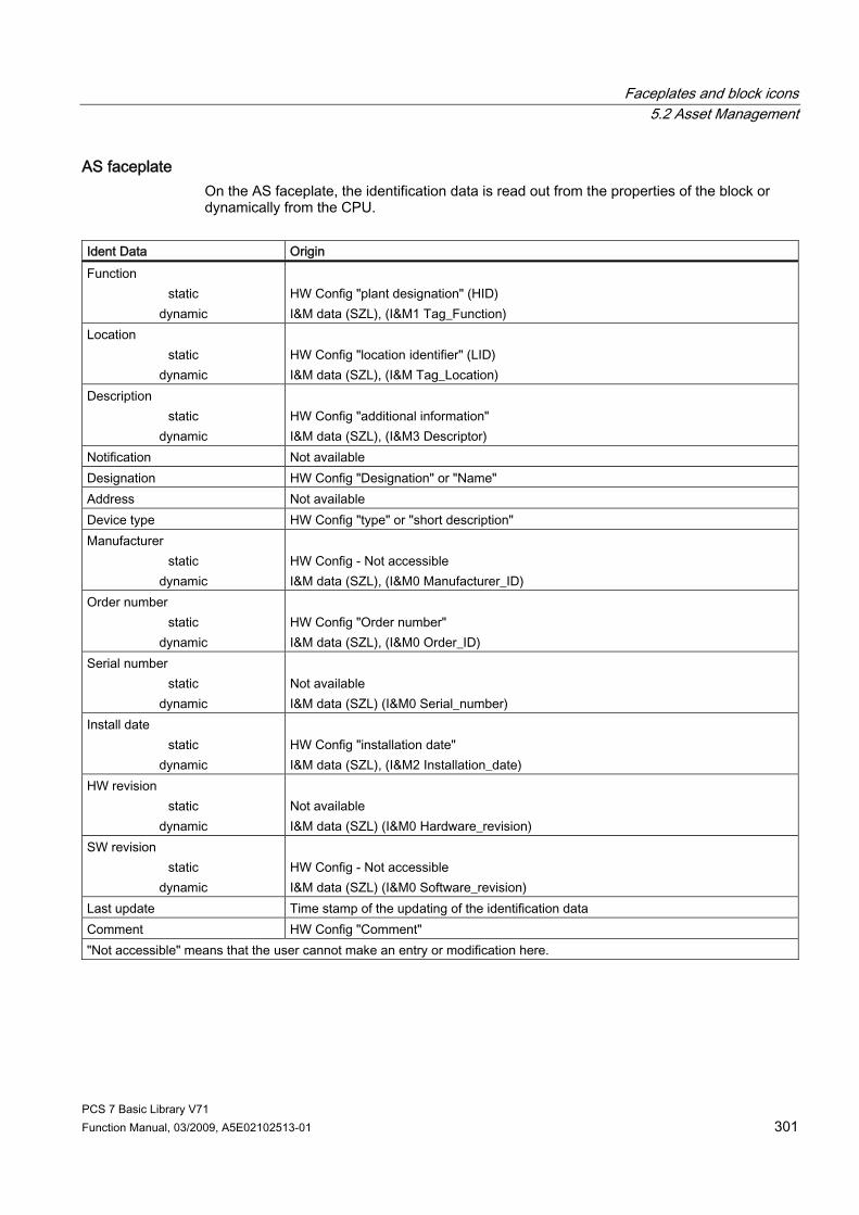
Faceplates and block icons 5.2 Asset Management
PCS 7 Basic Library V71 Function Manual, 03/2009, A5E02102513-01 301
AS faceplate On the AS faceplate, the identification data is read out from the properties of the block or dynamically from the CPU.
Ident Data Origin Function
static dynamic
HW Config "plant designation" (HID) I&M data (SZL), (I&M1 Tag_Function)
Location static
dynamic
HW Config "location identifier" (LID) I&M data (SZL), (I&M Tag_Location)
Description static
dynamic
HW Config "additional information" I&M data (SZL), (I&M3 Descriptor)
Notification Not available Designation HW Config "Designation" or "Name" Address Not available Device type HW Config "type" or "short description" Manufacturer
static dynamic
HW Config - Not accessible I&M data (SZL), (I&M0 Manufacturer_ID)
Order number static
dynamic
HW Config "Order number" I&M data (SZL), (I&M0 Order_ID)
Serial number static
dynamic
Not available I&M data (SZL) (I&M0 Serial_number)
Install date static
dynamic
HW Config "installation date" I&M data (SZL), (I&M2 Installation_date)
HW revision static
dynamic
Not available I&M data (SZL) (I&M0 Hardware_revision)
SW revision static
dynamic
HW Config - Not accessible I&M data (SZL) (I&M0 Software_revision)
Last update Time stamp of the updating of the identification data Comment HW Config "Comment" "Not accessible" means that the user cannot make an entry or modification here.
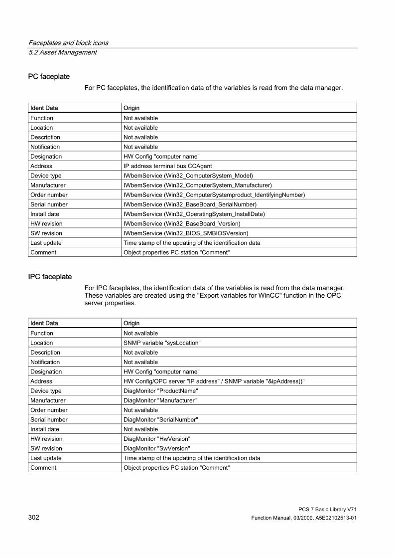
Faceplates and block icons 5.2 Asset Management
PCS 7 Basic Library V71 302 Function Manual, 03/2009, A5E02102513-01
PC faceplate For PC faceplates, the identification data of the variables is read from the data manager.
Ident Data Origin Function Not available Location Not available Description Not available Notification Not available Designation HW Config "computer name" Address IP address terminal bus CCAgent Device type IWbemService (Win32_ComputerSystem_Model) Manufacturer IWbemService (Win32_ComputerSystem_Manufacturer) Order number IWbemService (Win32_ComputerSystemproduct_IdentifyingNumber) Serial number IWbemService (Win32_BaseBoard_SerialNumber) Install date IWbemService (Win32_OperatingSystem_InstallDate) HW revision IWbemService (Win32_BaseBoard_Version) SW revision IWbemService (Win32_BIOS_SMBIOSVersion) Last update Time stamp of the updating of the identification data Comment Object properties PC station "Comment"
IPC faceplate For IPC faceplates, the identification data of the variables is read from the data manager. These variables are created using the "Export variables for WinCC" function in the OPC server properties.
Ident Data Origin Function Not available Location SNMP variable "sysLocation" Description Not available Notification Not available Designation HW Config "computer name" Address HW Config/OPC server "IP address" / SNMP variable "&ipAddress()" Device type DiagMonitor "ProductName" Manufacturer DiagMonitor "Manufacturer" Order number Not available Serial number DiagMonitor "SerialNumber" Install date Not available HW revision DiagMonitor "HwVersion" SW revision DiagMonitor "SwVersion" Last update Time stamp of the updating of the identification data Comment Object properties PC station "Comment"

Faceplates and block icons 5.2 Asset Management
PCS 7 Basic Library V71 Function Manual, 03/2009, A5E02102513-01 303
OSM faceplate For OSM faceplates, the Ident data of the variables are read from the data manager. These variables are created using the "Export variables for WinCC" function in the OPC server properties.
Ident Data Origin Function WBM "automationFunctionTag" **) Location WBM "System Location" / SNMP variable "sysLocation" Description Not available Notification Not available Designation HW Config/OPC server "Name" Address HW Config/OPC server "IP address" / SNMP variable "&ipAddress()" Device type WBM "Device Type" / SNMP variable "sysDesr" Manufacturer WBM "automationManufacturerId" **) Order number SNMP variable "snInfoOrderNr" **) Serial number SNMP variable "snInfoSerialNr" **) Install date Not available HW revision SNMP variable "snHWVersion" **) SW revision SNMP variable "snSWVersion" **) Last update Time stamp of the updating of the identification data Comment HW Config/OPC server "Comment" WBM = Web based management (Web interface of the network object) **) If the SNMP "MIB-II" profile is used, this data is not available
PDM faceplate On the PDM faceplate, the ident data is read in XML format via a COM interface to PDM.
Ident Data Origin Function EDD PDM "TAG" Location EDD PDM "Install location" Description EDD PDM "Descriptor" Notification EDD PDM "Message" Designation HW Config "Designation" or "Name" Address Not available Device type EDD PDM "Product designation" Manufacturer EDD PDM "Manufacturer" Order number EDD PDM "Device order number" Serial number EDD PDM "Device serial number" Install date EDD PDM "Install date" HW revision EDD PDM "Hardware revision" SW revision EDD PDM "Software revision" Last update Time stamp of the updating of the PDM database Comment HW Config "Comment"

Faceplates and block icons 5.2 Asset Management
PCS 7 Basic Library V71 304 Function Manual, 03/2009, A5E02102513-01
ASSETMON faceplate On the ASSETMON faceplate, the ident data is read out in XML format via a COM interface to PDM or from variables of the data manager.
Ident Data Origin Function EDD PDM "TAG" Location EDD PDM "Install location" Description EDD PDM "Descriptor" Notification EDD PDM "Message" Designation EDD PDM "TAG" Address Not available Device type EDD PDM "Product designation" Manufacturer EDD PDM "Manufacturer" Order number EDD PDM "Device order number" Serial number EDD PDM "Device serial number" Install date EDD PDM "Install date" HW revision EDD PDM "Hardware revision" SW revision EDD PDM "Software revision" Last update Time stamp of the updating of the PDM database Comment CFC "Block comment"
Additional information You will find more information in: Global representations and views of asset faceplates (Page 305)

Faceplates and block icons 5.2 Asset Management
PCS 7 Basic Library V71 Function Manual, 03/2009, A5E02102513-01 305
5.2.10 Global Representations and Views of Asset Faceplates
Introduction The following representations and views appear in all asset faceplates.
Icons for diagnostics and maintenance

Faceplates and block icons 5.2 Asset Management
PCS 7 Basic Library V71 306 Function Manual, 03/2009, A5E02102513-01
Icons in the faceplate
Meaning Icons
Group display with a maintenance alarm Indicates the group request status that represents the component in the hierarchical group display.
Possible group display statuses Maintenance alarm Maintenance request Maintenance required Good
Maintenance status display with a maintenance alarm Indicates the current total status of the component. It is formed from the sum of the individual statuses of a redundant component and the response/action of the operator. If the operator has not made any settings, the 8 icons listed under "Before operator action" can be displayed in the status display. If the operator performs a status change, the 3 icons listed under "After operator action" can be displayed in the status display. The operator changes the maintenance status in the faceplate "Maintenance" view.
Before operator action:
Maintenance alarm
Maintenance request
Maintenance required
Component good
Local operation
At least one process value is being simulated
Out of service
Component passivated
Untested/unknown
Configuration changed After operator action:
State change to Maintenance alarm
State change to Maintenance required
State change to Maintenance request

Faceplates and block icons 5.2 Asset Management
PCS 7 Basic Library V71 Function Manual, 03/2009, A5E02102513-01 307
Icons in the faceplate
Meaning Icons
Status display with icon Question mark = status unclear or not yet clear. Indicates the current processing status of the component. 1. Normal status (no diagnostics pending) --> no icon. 2. Pending diagnostics with no operator response --> no
icon. 3. Action triggered by operator as
confirmation/reclassification/job --> "?" icon; no activity on the component.
4. Action as in progress --> "In progress" icon
Repairing component (in progress)
Component status display If 2 icons are displayed under "Component", these indicate the component itself and its redundant component. If the components are not redundant, only one icon with text appears under "Component". The icons listed under "Component" indicate the original status of the component, as reported by the AS.
Possible statuses in the status display
Maintenance alarm
Maintenance request
Maintenance required
Component good
Local operation/local Overwrite
At least one process value is being simulated
Out of service
Component passivated
Untested/unknown
Configuration changed
Note If the maintenance status is "Untested/unknown", all the other dynamic displays in the asset-management faceplates are not relevant for this instance.
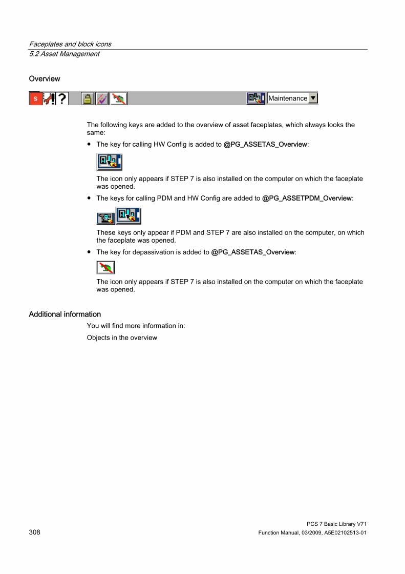
Faceplates and block icons 5.2 Asset Management
PCS 7 Basic Library V71 308 Function Manual, 03/2009, A5E02102513-01
Overview
The following keys are added to the overview of asset faceplates, which always looks the same: ● The key for calling HW Config is added to @PG_ASSETAS_Overview:
The icon only appears if STEP 7 is also installed on the computer on which the faceplate was opened.
● The keys for calling PDM and HW Config are added to @PG_ASSETPDM_Overview:
These keys only appear if PDM and STEP 7 are also installed on the computer, on which the faceplate was opened.
● The key for depassivation is added to @PG_ASSETAS_Overview:
The icon only appears if STEP 7 is also installed on the computer on which the faceplate was opened.
Additional information You will find more information in: Objects in the overview

PCS 7 Basic Library V71 Function Manual, 03/2009, A5E02102513-01 309
Appendix 66.1 "Blocks - basic library" technical data
Overview The table below contains the technical data for the blocks. The table columns have the following meanings: ● Block type name
The symbolic identifier in the symbol table of the library for the relevant FB or FC. Must be unique within the project.
● Object name Consists of the block type (FB, FC) and number.
● Typical execution time CPU runtime for processing the corresponding block program under normal circumstances (for example, for a driver, this is the execution time in the cyclic interrupt OB (OB3x), without generation of a channel error message). The table below shows the runtime of blocks in a 417-4 CPU. The block runtime on other CPUs depends on the CPU performance.
● Block length in load/work memory Memory requirements of the program code, once for each block type.
● Length of instance data in load/work memory Memory requirement of an instance DB.
● Temporary memory The local-data memory required in a priority class when the block is called. This limit is CPU specific. When it is exceeded, you have to check the CPU configuration in the local-data memory and, if necessary, distribute it amongst the OBs to meet the actual requirements.

Appendix 6.1 "Blocks - basic library" technical data
PCS 7 Basic Library V71 310 Function Manual, 03/2009, A5E02102513-01
● Multiple instance block The specified blocks are used by the block concerned, and must exist in the user program. They can be found in the same library.
Block (Type name)
FB/FC no.
Typical run time CPU 417-4 (µs)
Block length in load/work memory (bytes)
Length of the instance data in the load/work memory (bytes)
Temporary memory (bytes)
Multiple instance block
ChkREAL FC 260 CONEC FB 88 98 10266 / 8642 1186 / 340 84 16 x SFB 35 CPU_RT FB 128 67 31434 / 27370 2800 / 1784 86 DIAG_AB FB 414 DPAY_V0 FB 108 159 1792 / 1202 542 / 70 22 DPAY_V1 FB 115 155 11206 / 8506 3588 / 1388 136 SFB 35 DPDIAGV0 FB 117 115 3980 / 2184 1800 / 194 66 DREP FB 113 19 4202 / 3038 1296 / 366 124 DREP_L FB 125 20 6578 / 5358 1406 / 486 52 2 x SFB 35 FM_CNT FB 126 36 1496 / 1060 546 / 140 10 FM_CO FB 79 18 3132 / 1780 1732 / 566 46 FRC_CFC FB 136 IMDRV_TS FB 129 MOD_1 FB 91 91 13202/ 10498 5946 / 4060 116 16 x SFB 35 MOD_2 FB 92 91 4912 / 3862 1120 / 346 68 SFB 35 MOD_3 FB 95 91 4984 / 3868 1280 / 442 66 SFB 35 MOD_4 FB 119 16 4988 / 3872 1288 / 448 66 SFB 35 MOD_64 FB 137 SFB 35 MOD_CP FB 98 104 3496 / 2540 1108 / 346 52 SFB 35 MOD_D1 FB 93 96 6850 / 5622 1186 / 340 80 SFB 35 MOD_D2 FB 94 97 12552 / 10752 1818 / 700 86 3 x SFB 35 MOD_D3 FB 134 103 13432 / 11442 3958 / 2164 90 3 x SFB 35 MOD_HA FB 97 18 10836 / 8938 2440 / 1090 82 5 x SFB 35 MOD_MS FB 96 99 5442 / 4282 1356 / 464 54 SFB 35 MOD_PAL0 FB 99 169 7758 / 6322 1814 / 740 84 2 x SFB 35 MOD_PAX0 FB 112 112 4470 / 3746 1006 / 490 50 2 x SFB 35
SFB 52 MODB_341 FB 80 594 4388 / 3666 1012 / 490 54 2 x SFB 35 OB_BEGIN FB 100 158 3012 / 2268 1206 / 630 120 OB_DIAG1 FB118 23 10886 / 8924 1690 / 306 116 SFB 35
SFB 52 OB_END FC280 4 514 / 86 - / - 4 OR_HA16C FB 133 181 8492 / 6972 2362 / 1146 70 5 x SFB 35 OR_M_16 FB 81 181 3682 / 2736 1176 / 410 50 SFB 35 OR_M_16C FB 84 183 8010 / 6516 2356 / 1146 70 SFB 35 OR_M_32 FB 82 268 3778 / 2736 1464 / 602 50 SFB 35
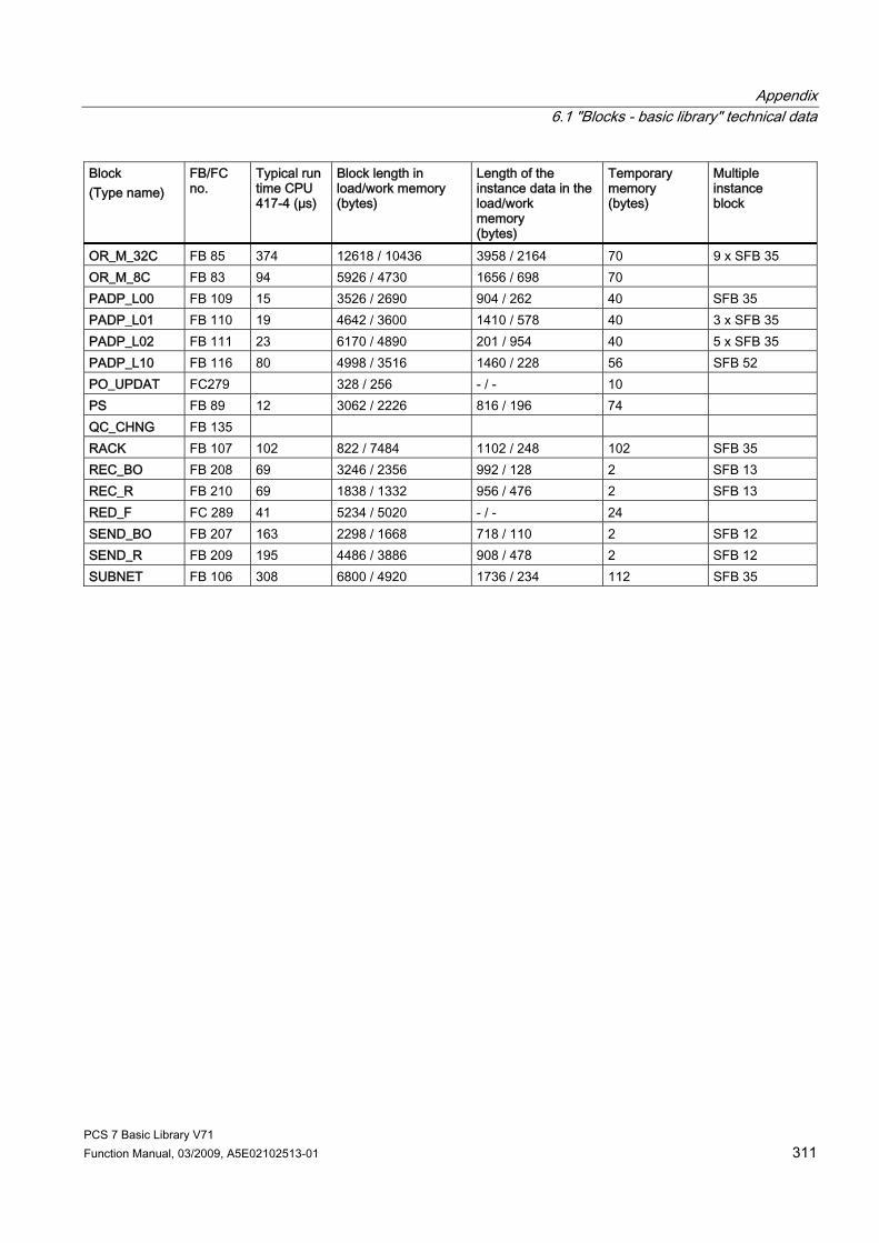
Appendix 6.1 "Blocks - basic library" technical data
PCS 7 Basic Library V71 Function Manual, 03/2009, A5E02102513-01 311
Block (Type name)
FB/FC no.
Typical run time CPU 417-4 (µs)
Block length in load/work memory (bytes)
Length of the instance data in the load/work memory (bytes)
Temporary memory (bytes)
Multiple instance block
OR_M_32C FB 85 374 12618 / 10436 3958 / 2164 70 9 x SFB 35 OR_M_8C FB 83 94 5926 / 4730 1656 / 698 70 PADP_L00 FB 109 15 3526 / 2690 904 / 262 40 SFB 35 PADP_L01 FB 110 19 4642 / 3600 1410 / 578 40 3 x SFB 35 PADP_L02 FB 111 23 6170 / 4890 201 / 954 40 5 x SFB 35 PADP_L10 FB 116 80 4998 / 3516 1460 / 228 56 SFB 52 PO_UPDAT FC279 328 / 256 - / - 10 PS FB 89 12 3062 / 2226 816 / 196 74 QC_CHNG FB 135 RACK FB 107 102 822 / 7484 1102 / 248 102 SFB 35 REC_BO FB 208 69 3246 / 2356 992 / 128 2 SFB 13 REC_R FB 210 69 1838 / 1332 956 / 476 2 SFB 13 RED_F FC 289 41 5234 / 5020 - / - 24 SEND_BO FB 207 163 2298 / 1668 718 / 110 2 SFB 12 SEND_R FB 209 195 4486 / 3886 908 / 478 2 SFB 12 SUBNET FB 106 308 6800 / 4920 1736 / 234 112 SFB 35

Appendix 6.2 OMODE Settings for SM Modules
PCS 7 Basic Library V71 312 Function Manual, 03/2009, A5E02102513-01
6.2 OMODE Settings for SM Modules
OMODE structure The table below shows the structure and meaning of the outputs OMODE_xx of data type DWORD:
Byte 3: 16#80: Value status "valid value"
16#00: Value status "invalid value" 16#40: Value status "invalid value"
(Channel error) (Higher-level error)
Byte 2: 16#01: Restart (OB 100) has been carried out 16#02: Measuring-range overshoot 16#04: Measuring range low limit exceeded
(Channel-error diagnostics) (Channel-error diagnostics)
Byte 1, 0 (low word): MODE (see above)
Example: 16#80010203 = value status "valid value", restart has been carried out, current 4 mA to 20mA

Appendix 6.3 MODE Settings for SM Modules
PCS 7 Basic Library V71 Function Manual, 03/2009, A5E02102513-01 313
6.3 MODE Settings for SM Modules
Measuring range coding of the analog input modules Depending on the measuring-range coding of the analog input modules, the parameter MODE_xx (measuring-range coding) corresponding to the channel must be specified in accordance with the table. When thermocouples are used there are various options for combining the measurement type (coding A) with the measuring range (coding B). In this case, the MODE_xx parameter must be calculated according to the following formula and the result written to the MODE input as an INTEGER value: MODE = 256 ∗ code A + code B Please note: The table displays codes A and B in binary format, and the result in hexadecimal format in the MODE parameter. Measuring type Coding
(A) Measuring range Code (B) MODE
(256∗A+B) Deactivated 16#0000
± 25 mV 2#1010 16#010A ± 50 mV 2#1011 16#010B ± 80 mV 2#0001 16#0101 ± 250 mV 2#0010 16#0102 ± 500 mV 2#0011 16#0103 ± 1 V 2#0100 16#0104 ± 2.5 V 2#0101 16#0105 ± 5 V 2#0110 16#0106 1 to 5 V 2#0111 16#0107 0 to 10 V 2#1000 16#0108 ± 10 V 2#1001 16#0109
Voltage 2#0001
± 100 mV 2#1100 16#010C ±3.2 mA 2#0000 16#0200 ± 5 mA 2#0101 16#0205 ± 10 mA 2#0001 16#0201 0 mA to 20 mA 2#0010 16#0202 4 mA to 20 mA 2#0011 16#0203
4-wire measuring transducer 2#0010
± 20 mA 2#0100 16#0204 HART interface 2#0111 4 mA to 20 mA 2#1100 16#070C
4 mA to 20 mA 2#0011 16#0303 2-wire measuring transducer 2#0011 ± 20 mA 2#0100 16#0304

Appendix 6.3 MODE Settings for SM Modules
PCS 7 Basic Library V71 314 Function Manual, 03/2009, A5E02102513-01
Measuring type Coding (A)
Measuring range Code (B) MODE (256∗A+B)
48 Ω 2#0000 16#0400 150 Ω 2#0010 16#0402 300 Ω 2#0100 16#0404 600 Ω 2#0110 16#0406 1000 Ω 2#0111 16#040E 3000 Ω 2#0111 16#0407 6000 Ω 2#1000 16#0408
Resistor 4-wire connection 2#0100
PTC 2#1111 16#040F 48 Ω 2#0000 16#0500 150 Ω 2#0010 16#0502 300 Ω 2#0100 16#0504 600 Ω 2#0110 16#0506 1000 Ω 2#0111 16#050E 3000 Ω 2#0111 16#0507 6000 Ω 2#1000 16#0508
Resistor 3-wire connection 2#0101
PTC 2#1111 16#050F 48 Ω 2#0000 16#0600 150 Ω 2#0010 16#0602 300 Ω 2#0100 16#0604 600 Ω 2#0110 16#0606 1000 Ω 2#0111 16#060E 3000 Ω 2#0111 16#0607 6000 Ω 2#1000 16#0608
Resistor 2-wire connection 2#0110
PTC 2#1111 16#060F Pt 100 climate range 2#0000 16#0800 Pt 200 climate range 2#0111 16#0807 Pt 500 climate range 2#1000 16#0808 Pt 1000 climate range 2#1001 16#0809 Ni 100 climate range 2#0001 16#0801 Ni 1000 climate range 2#1010 16#080A Pt 100 standard range 2#0010 16#0802 Pt 200 standard range 2#0011 16#0803 Pt 500 standard range 2#0100 16#0804 Pt 1000 standard range 2#0101 16#0805 Ni 100 standard range 2#1011 16#080B Ni 1000 standard range 2#0110 16#0806 Ni 120 standard range 2#1100 16#080C Ni 120 climate range 2#1101 16#080D Cu 10 climate range 2#1110 16#080E Cu 10 standard range 2#1111 16#080F
Thermocouple + linear, 4-wire connection
2#1000
Ni 200 standard range 2#10000 16#0810

Appendix 6.3 MODE Settings for SM Modules
PCS 7 Basic Library V71 Function Manual, 03/2009, A5E02102513-01 315
Measuring type Coding (A)
Measuring range Code (B) MODE (256∗A+B)
Ni 200 climate range 2#10001 16#0811 Ni 500 standard range 2#10010 16#0812 Ni 500 climate range 2#10011 16#0813 Pt 10 GOST climatic 2#10100 16#0814 Pt 10 GOST standard (TC = 3910)
2#10101 16#0815
Pt 50 GOST climatic 2#10110 16#0816 Pt 50 GOST standard (TC = 3910)
2#10111 16#0817
Pt 100 GOST climatic 2#11000 16#0818 Pt 100 GOST standard (TC = 3910)
2#11001 16#0819
Pt 500 GOST climatic 2#11010 16#081A Pt 500 GOST standard (TC = 3910)
2#11011 16#081B
Pt 10 GOST climatic 2#11100 16#081C Cu 10 GOST standard (TC = 426)
2#11101 16#081D
Pt 50 GOST climatic 2#11110 16#081E Cu 50 GOST standard (TC = 426)
2#11111 16#081F
Pt 100 GOST climatic 2#100000 16#0820 Cu 100 GOST standard (TC = 426)
2#100001 16#0821
Pt 100 GOST climatic 2#100010 16#0822 Ni 100 GOST Standard 2#100011 16#0823 Pt 10 GOST standard (TC = 3850)
2#1010101 16#0855
Pt 50 GOST standard (TC = 3850)
2#1010111 16#0857
Pt 100 GOST standard (TC = 3850)
2#1011001 16#0859
Pt 500 GOST standard (TC = 3850)
2#1011011 16#085B
Cu 10 GOST standard (TC = 428)
2#10011101 16#089D
Cu 50 GOST standard (TC = 428)
2#10011111 16#089F
Cu 100 GOST standard (TC = 428)
2#10100001 16#08A1
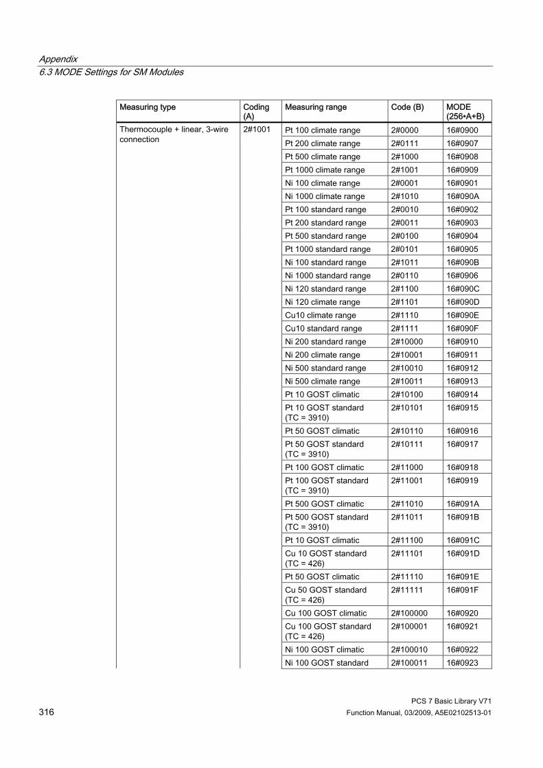
Appendix 6.3 MODE Settings for SM Modules
PCS 7 Basic Library V71 316 Function Manual, 03/2009, A5E02102513-01
Measuring type Coding (A)
Measuring range Code (B) MODE (256∗A+B)
Pt 100 climate range 2#0000 16#0900 Pt 200 climate range 2#0111 16#0907 Pt 500 climate range 2#1000 16#0908 Pt 1000 climate range 2#1001 16#0909 Ni 100 climate range 2#0001 16#0901 Ni 1000 climate range 2#1010 16#090A Pt 100 standard range 2#0010 16#0902 Pt 200 standard range 2#0011 16#0903 Pt 500 standard range 2#0100 16#0904 Pt 1000 standard range 2#0101 16#0905 Ni 100 standard range 2#1011 16#090B Ni 1000 standard range 2#0110 16#0906 Ni 120 standard range 2#1100 16#090C Ni 120 climate range 2#1101 16#090D Cu10 climate range 2#1110 16#090E Cu10 standard range 2#1111 16#090F Ni 200 standard range 2#10000 16#0910 Ni 200 climate range 2#10001 16#0911 Ni 500 standard range 2#10010 16#0912 Ni 500 climate range 2#10011 16#0913 Pt 10 GOST climatic 2#10100 16#0914 Pt 10 GOST standard (TC = 3910)
2#10101 16#0915
Pt 50 GOST climatic 2#10110 16#0916 Pt 50 GOST standard (TC = 3910)
2#10111 16#0917
Pt 100 GOST climatic 2#11000 16#0918 Pt 100 GOST standard (TC = 3910)
2#11001 16#0919
Pt 500 GOST climatic 2#11010 16#091A Pt 500 GOST standard (TC = 3910)
2#11011 16#091B
Pt 10 GOST climatic 2#11100 16#091C Cu 10 GOST standard (TC = 426)
2#11101 16#091D
Pt 50 GOST climatic 2#11110 16#091E Cu 50 GOST standard (TC = 426)
2#11111 16#091F
Cu 100 GOST climatic 2#100000 16#0920 Cu 100 GOST standard (TC = 426)
2#100001 16#0921
Ni 100 GOST climatic 2#100010 16#0922
Thermocouple + linear, 3-wire connection
2#1001
Ni 100 GOST standard 2#100011 16#0923
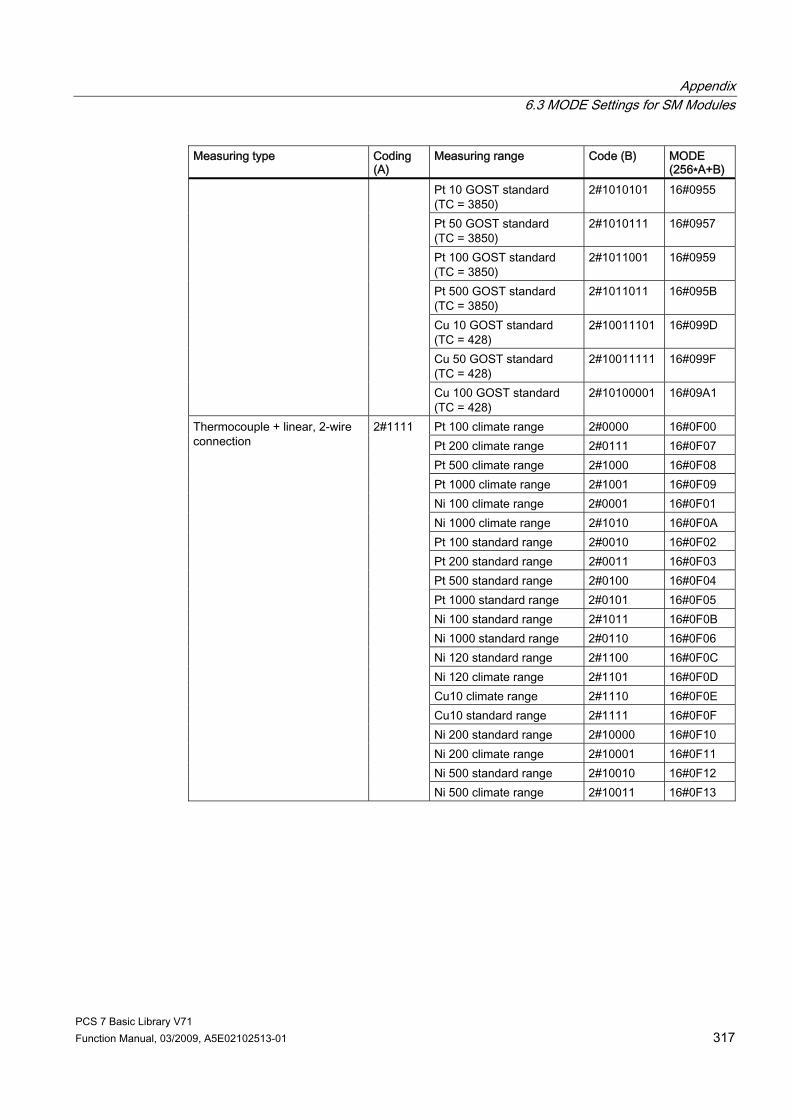
Appendix 6.3 MODE Settings for SM Modules
PCS 7 Basic Library V71 Function Manual, 03/2009, A5E02102513-01 317
Measuring type Coding (A)
Measuring range Code (B) MODE (256∗A+B)
Pt 10 GOST standard (TC = 3850)
2#1010101 16#0955
Pt 50 GOST standard (TC = 3850)
2#1010111 16#0957
Pt 100 GOST standard (TC = 3850)
2#1011001 16#0959
Pt 500 GOST standard (TC = 3850)
2#1011011 16#095B
Cu 10 GOST standard (TC = 428)
2#10011101 16#099D
Cu 50 GOST standard (TC = 428)
2#10011111 16#099F
Cu 100 GOST standard (TC = 428)
2#10100001 16#09A1
Pt 100 climate range 2#0000 16#0F00 Pt 200 climate range 2#0111 16#0F07 Pt 500 climate range 2#1000 16#0F08 Pt 1000 climate range 2#1001 16#0F09 Ni 100 climate range 2#0001 16#0F01 Ni 1000 climate range 2#1010 16#0F0A Pt 100 standard range 2#0010 16#0F02 Pt 200 standard range 2#0011 16#0F03 Pt 500 standard range 2#0100 16#0F04 Pt 1000 standard range 2#0101 16#0F05 Ni 100 standard range 2#1011 16#0F0B Ni 1000 standard range 2#0110 16#0F06 Ni 120 standard range 2#1100 16#0F0C Ni 120 climate range 2#1101 16#0F0D Cu10 climate range 2#1110 16#0F0E Cu10 standard range 2#1111 16#0F0F Ni 200 standard range 2#10000 16#0F10 Ni 200 climate range 2#10001 16#0F11 Ni 500 standard range 2#10010 16#0F12
Thermocouple + linear, 2-wire connection
2#1111
Ni 500 climate range 2#10011 16#0F13
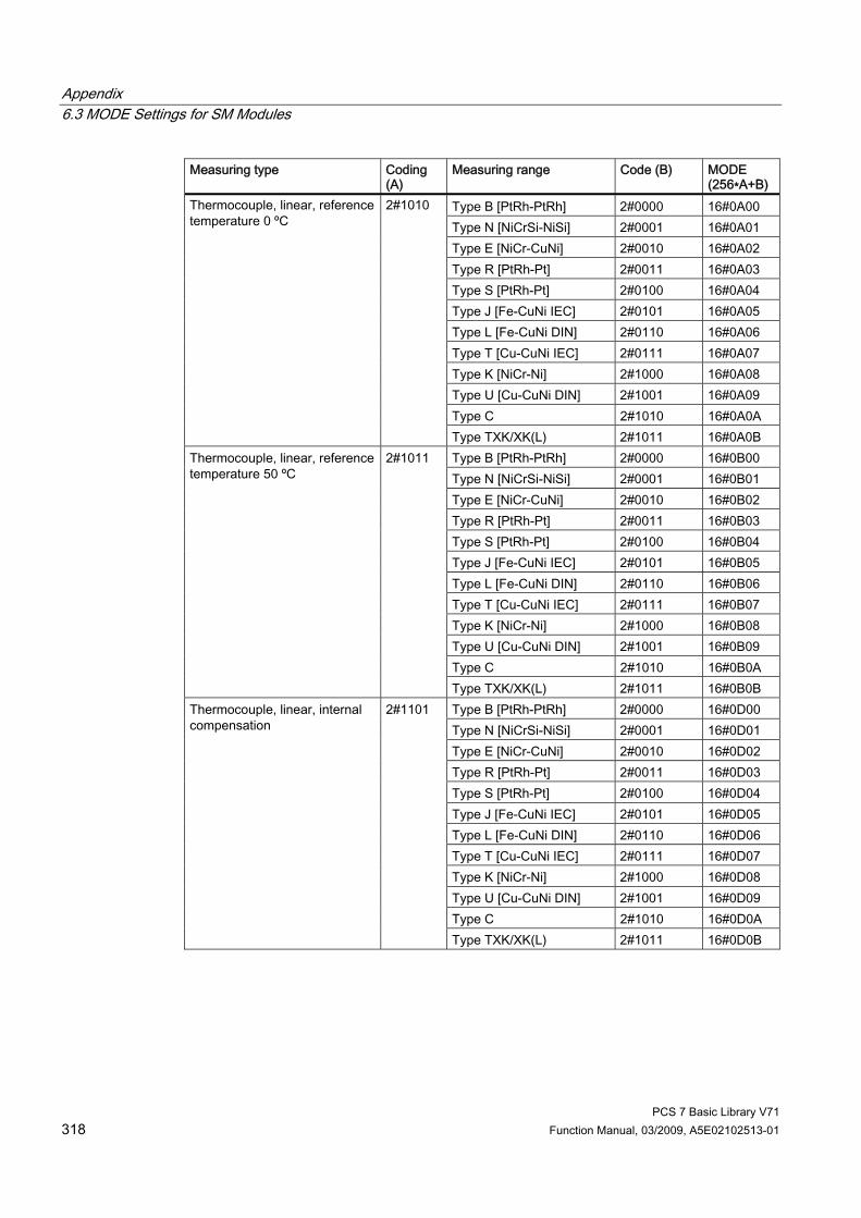
Appendix 6.3 MODE Settings for SM Modules
PCS 7 Basic Library V71 318 Function Manual, 03/2009, A5E02102513-01
Measuring type Coding (A)
Measuring range Code (B) MODE (256∗A+B)
Type B [PtRh-PtRh] 2#0000 16#0A00 Type N [NiCrSi-NiSi] 2#0001 16#0A01 Type E [NiCr-CuNi] 2#0010 16#0A02 Type R [PtRh-Pt] 2#0011 16#0A03 Type S [PtRh-Pt] 2#0100 16#0A04 Type J [Fe-CuNi IEC] 2#0101 16#0A05 Type L [Fe-CuNi DIN] 2#0110 16#0A06 Type T [Cu-CuNi IEC] 2#0111 16#0A07 Type K [NiCr-Ni] 2#1000 16#0A08 Type U [Cu-CuNi DIN] 2#1001 16#0A09 Type C 2#1010 16#0A0A
Thermocouple, linear, reference temperature 0 ºC
2#1010
Type TXK/XK(L) 2#1011 16#0A0B Type B [PtRh-PtRh] 2#0000 16#0B00 Type N [NiCrSi-NiSi] 2#0001 16#0B01 Type E [NiCr-CuNi] 2#0010 16#0B02 Type R [PtRh-Pt] 2#0011 16#0B03 Type S [PtRh-Pt] 2#0100 16#0B04 Type J [Fe-CuNi IEC] 2#0101 16#0B05 Type L [Fe-CuNi DIN] 2#0110 16#0B06 Type T [Cu-CuNi IEC] 2#0111 16#0B07 Type K [NiCr-Ni] 2#1000 16#0B08 Type U [Cu-CuNi DIN] 2#1001 16#0B09 Type C 2#1010 16#0B0A
Thermocouple, linear, reference temperature 50 ºC
2#1011
Type TXK/XK(L) 2#1011 16#0B0B Type B [PtRh-PtRh] 2#0000 16#0D00 Type N [NiCrSi-NiSi] 2#0001 16#0D01 Type E [NiCr-CuNi] 2#0010 16#0D02 Type R [PtRh-Pt] 2#0011 16#0D03 Type S [PtRh-Pt] 2#0100 16#0D04 Type J [Fe-CuNi IEC] 2#0101 16#0D05 Type L [Fe-CuNi DIN] 2#0110 16#0D06 Type T [Cu-CuNi IEC] 2#0111 16#0D07 Type K [NiCr-Ni] 2#1000 16#0D08 Type U [Cu-CuNi DIN] 2#1001 16#0D09 Type C 2#1010 16#0D0A
Thermocouple, linear, internal compensation
2#1101
Type TXK/XK(L) 2#1011 16#0D0B

Appendix 6.3 MODE Settings for SM Modules
PCS 7 Basic Library V71 Function Manual, 03/2009, A5E02102513-01 319
Measuring type Coding (A)
Measuring range Code (B) MODE (256∗A+B)
Type B [PtRh-PtRh] 2#0000 16#0E00 Type N [NiCrSi-NiSi] 2#0001 16#0E01 Type E [NiCr-CuNi] 2#0010 16#0E02 Type R [PtRh-Pt] 2#0011 16#0E03 Type S [PtRh-Pt] 2#0100 16#0E04 Type J [Fe-CuNi IEC] 2#0101 16#0E05 Type L [Fe-CuNi DIN] 2#0110 16#0E06 Type T [Cu-CuNi IEC] 2#0111 16#0E07 Type K [NiCr-Ni] 2#1000 16#0E08 Type U [Cu-CuNi DIN] 2#1001 16#0E09 Type C 2#1010 16#0E0A
Thermocouple, linear, external compensation
2#1110
Type TXK/XK(L) 2#1011 16#0E0B
Effect of the temperature coefficients on the measuring range ● Setting TC = 3850 at GOST Standard Pt10, Pt50, Pt100, Pt500 sets Bit 7 in the
measuring range byte (0x40) ● Setting TC = 428 at GOST Standard Cu10, Cu50, Cu100 sets Bit 8 in the measuring
range byte (0x80)
Measuring range coding of the analog output modules Depending on the measuring-range coding of the analog output modules, the parameter MODE_xx (measuring-range coding) corresponding to the channel must be specified in accordance with the table. Measuring Type Measuring Range MODE
± 5 V 16#0106 1 V to 5 V 16#0107 0 V to 10 V 16#0108
Voltage
± 10 V 16#0109 0 mA to 20 mA 16#0202 4 mA to 20 mA 16#0203
Current
± 20 mA 16#0204 HART interface 4 mA to 20 mA 16#070C
Measuring-Range Coding of the Digital Input and Output Modules With digital input modules and digital output modules, there is no measurement type and no measurement range: MODE = 16#FFFF (with DI) MODE = 16#FFFE (with DO)

Appendix 6.4 MODE settings for PA devices
PCS 7 Basic Library V71 320 Function Manual, 03/2009, A5E02102513-01
6.4 MODE settings for PA devices MODE_xx input parameters are available for a maximum of 32 slots of a PA field device. Their initial value is zero (no read/write access). You must set the combination selected from the options of the PROFIBUS PA 3.0 profile at the MODE_xx input of each slot channel xx: Block I/O (parameters)
(cyclic data) permissible combination and sequence
Input (I)/Output (O) (PLS view)
MODE 16#xxyy, O=xx I=yy
Analog input (PA_AI) OUT I 16#0001 Totalizer (PA_TOT) TOTAL I 16#000F Totalizer (PA_TOT) TOTAL
SET_TOT I O
16#070F
Totalizer (PA_TOT) TOTAL SET_TOT MODE_TOT
I O O
16#080F
Analog output (PA_AO) SP O 16#0100 Analog output (PA_AO) SP
READBACK POS_D
O I I
16#0103
Analog output (PA_AO) SP CHECK_BACK
O I
16#0104
Analog output (PA_AO) SP READBACK POS_D CHECK_BACK
O I I I
16#0105
Analog output (PA_AO) RCAS_IN, RCAS_OUT
O I
16#0206
Analog output (PA_AO) RCAS_IN, RCAS_OUT, CHECK_BACK
O I I
16#0207
Analog output (PA_AO) SP RCAS_IN READBACK RCAS_OUT POS_D CHECK_BACK
O O I I I I
16#0308
Discrete input (PA_DI) OUT_D I 16#0002 Discrete output (PA_DO) SP_D O 16#0400 Discrete output (PA_DO) SP_D
READBACK_D O I
16#0409
Discrete output (PA_DO) SP_D CHECKBACK_D
O I
16#040A
Discrete output (PA_DO) SP_D READBACK_D CHECK_BACK_D
O I I
16#040B
Discrete output (PA_DO) RCAS_IN_D RCAS_OUT_D
O I
16#050C

Appendix 6.4 MODE settings for PA devices
PCS 7 Basic Library V71 Function Manual, 03/2009, A5E02102513-01 321
Block I/O (parameters) (cyclic data) permissible combination and sequence
Input (I)/Output (O) (PLS view)
MODE 16#xxyy, O=xx I=yy
Discrete output (PA_DO) RCAS_IN_D RCAS_OUT_D CHECK_BACK_D
O I I
16#050D
Discrete output (PA_DO) SP_D RCAS_IN_D READBACK_D RCAS_OUT_D CHECK_BACK_D
O O I I I
16#060E

Appendix 6.5 Error Information of Output Parameter MSG_STAT
PCS 7 Basic Library V71 322 Function Manual, 03/2009, A5E02102513-01
6.5 Error Information of Output Parameter MSG_STAT The messages can be disabled by setting input EN_MSG = FALSE (output MSG_STAT(_x) remains unchanged). Block ALARM8_P(_x) is called in the acyclic OBs and in OB1 if message suppression is not enabled. Error information of ALARM_8P(_x) - messages cannot be output - is indicated at output parameter MSG_STAT(_x). Details on the error information of output parameter MSG_STAT and on the acknowledgment word MSG_ACK(_x) of ALARM_8P are found in the Online Help of SF B35 (ALARM_8P).

Appendix 6.6 Addressing
PCS 7 Basic Library V71 Function Manual, 03/2009, A5E02102513-01 323
6.6 Addressing
Rules If you do not use the CFC function “Generate module drivers”, you must set the logical basic address of the module created with HW Config at the LADDR input parameter. If input SUBN_TYP = FALSE, the RACK of the module is connected to an integrated DP interface (distributed I/O device interface) of the CPU module by means of a line. Otherwise, you must set SUBN_TYP = TRUE. The following points are generally to be observed for all SM and PA modules: ● The basic address of modules equipped only with inputs, i.e., modules which only write
data to the input area of the CPU process image, can be fetched directly from HW Config; for example: the module SM331 AI 8x12Bit 6ES7331-7KF01-0AB0:
Address input range (HW Config)
Address output range (HW Config)
LADDR (decimal/hex)
512 - 512 / 16#0200
● The MSB (most significant bit) must be set in the basic address fetched from HW Config for modules equipped only with outputs, i.e., modules which only read data from the output area of the CPU process image; for example, module SM 332 AO 4x12Bit 6ES7332-5HD01-0AB0:
Address input range (HW Config)
Address output range (HW Config)
LADDR (decimal/hex)
- 512 -32256 / 16#8200
● The basic address of the input range must be set at input LADDR and the basic address of the output range from HW Config must be set at input LADDR1 for mixed modules, i.e., modules which write data to the input area and read data from the output area of the CPU process image; for example, module SM 323 DI/O 8x24V/05A 6ES7323-1BH81-0AA0:
Address input range (HW Config)
Address output range (HW Config)
LADDR (decimal/hex)
LADDR1 (decimal/hex)
12 12 12/16# 000C 12/16# 000C

Appendix 6.7 Message Classes
PCS 7 Basic Library V71 324 Function Manual, 03/2009, A5E02102513-01
6.7 Message Classes
Message classes Message classes are used to group messages according to their cause. The following message classes are used in the SIMATIC process control system: ● Process messages triggered when process-specific monitoring values (for example,
alarms, warnings, high/low tolerances, general process messages) are reached or exceeded.
● Process-control messages; output by the control system (system messages) or the I/O units (errors in the field), or for preventive maintenance.
● Requests for operator input which, in the case of certain operation sequences, draw the operator's attention to the necessity of an operator intervention (for example, request to acknowledge a stepping operation manually in order to enable transition) or operation logs.
Table of message classes and their meaning Message class Meaning With acknowledgmentAH Alarm high (High High Alarm) Yes AL Alarm low (Low Low Alarm) Yes WH Warning high (High Alarm) Yes WL Warning low (Low Alarm) Yes TH Tolerance high (Tolerance High) Yes TL Tolerance low (Tolerance Low) Yes F AS control system message (error) Yes S AS control system message (fault) Yes S* OS control system message (fault) Yes M Preventive maintenance (Maintenance) Yes PM Process message (Process Message) Yes - Operating message No OR Operator request (Operator Request) No OM *1) Operator message (Operation Message) No SA Status AS No SO Status OS No
*1) If the block is used for operation messages, the inputs I_1, ... have to be supplied with pulses. Assignment of the static value "1" would lead to multiple messages.

Appendix 6.8 Dependencies
PCS 7 Basic Library V71 Function Manual, 03/2009, A5E02102513-01 325
6.8 Dependencies
Dependency on the FM_CO block The FM_CO block (PCS 7 Basic Library) coordinates the reading of data records for the FM_CNT, FMCS_PID, FMT_PID, and READ355P blocks. Therefore, when installing these blocks you must ensure that the driver generator installs FM_CO in the fastest cyclic-interrupt OB of one of the blocks named above. This OB must not run slower than 30 s or faster than 25 ms.
Notes on reading data records In an ET 200M with n controller blocks, reading of data records is activated every n+1 cycles (ideally, when the installation sequence tallies with the interconnection). This means that, in the worst case, a setpoint changed by means of a faceplate will only be viewed by the operator after n+1 cycles (e.g. this would amount to 17 s for OB 32 (1,000 ms) with 4 controller modules and 16 blocks). The same applies for position feedback for the step controller. At the time of changeover (manual/auto), the manipulated variable LMN is set to an out-of-date value.
Changing the visualization time You can reduce the visualization time as follows: ● Install the controller blocks in a faster OB
or ● Distribute the controller modules over several ET 200 stations.
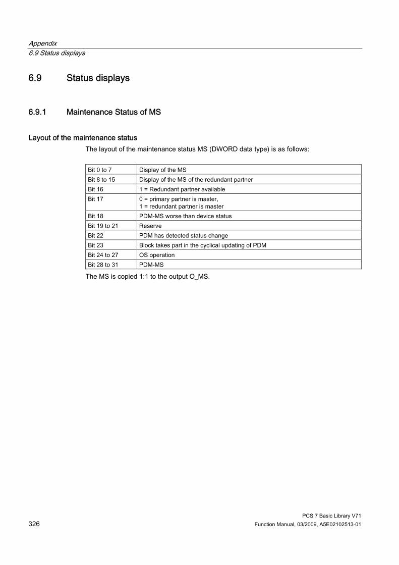
Appendix 6.9 Status displays
PCS 7 Basic Library V71 326 Function Manual, 03/2009, A5E02102513-01
6.9 Status displays
6.9.1 Maintenance Status of MS
Layout of the maintenance status The layout of the maintenance status MS (DWORD data type) is as follows: Bit 0 to 7 Display of the MS Bit 8 to 15 Display of the MS of the redundant partner Bit 16 1 = Redundant partner available Bit 17 0 = primary partner is master,
1 = redundant partner is master Bit 18 PDM-MS worse than device status Bit 19 to 21 Reserve Bit 22 PDM has detected status change Bit 23 Block takes part in the cyclical updating of PDM Bit 24 to 27 OS operation Bit 28 to 31 PDM-MS
The MS is copied 1:1 to the output O_MS.
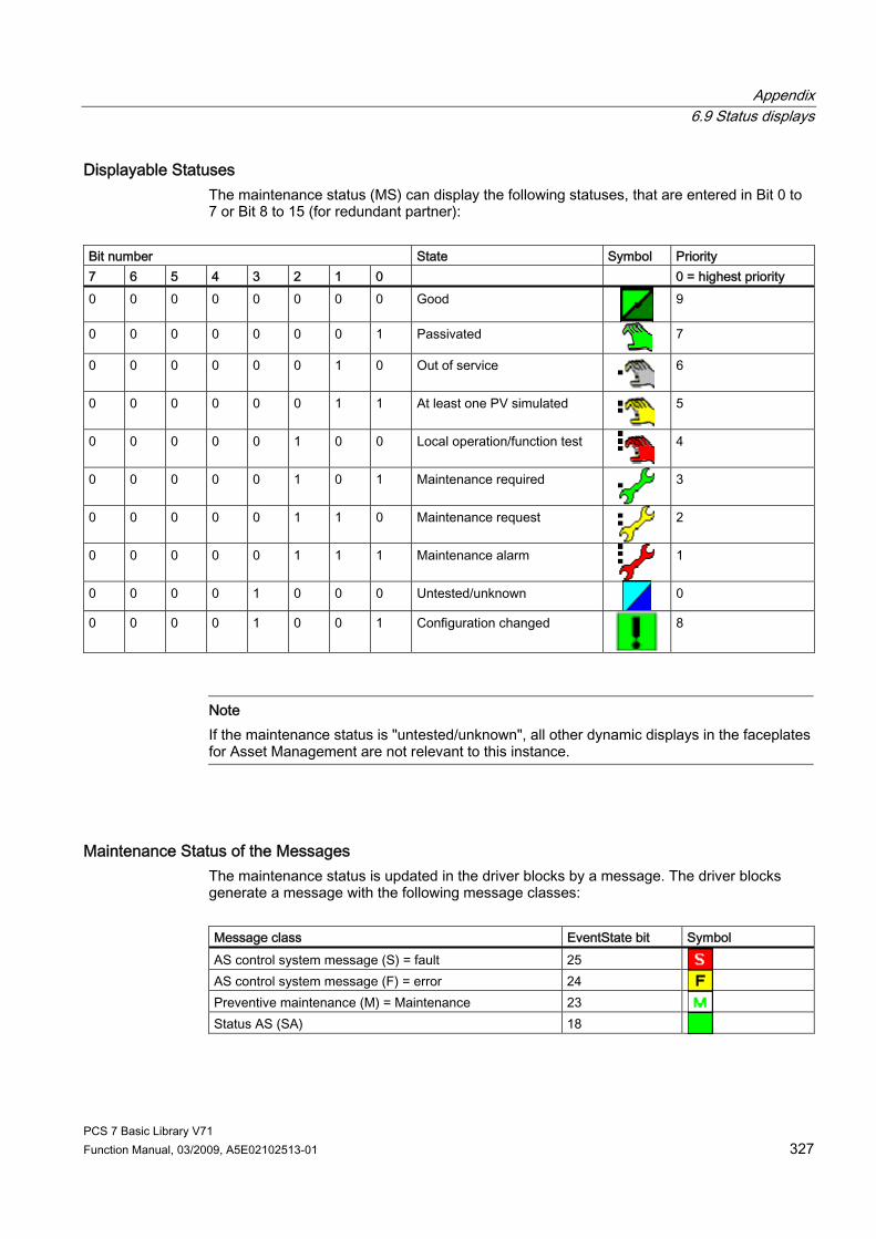
Appendix 6.9 Status displays
PCS 7 Basic Library V71 Function Manual, 03/2009, A5E02102513-01 327
Displayable Statuses The maintenance status (MS) can display the following statuses, that are entered in Bit 0 to 7 or Bit 8 to 15 (for redundant partner):
Bit number State Symbol Priority 7 6 5 4 3 2 1 0 0 = highest priority 0 0 0 0 0 0 0 0 Good
9
0 0 0 0 0 0 0 1 Passivated
7
0 0 0 0 0 0 1 0 Out of service
6
0 0 0 0 0 0 1 1 At least one PV simulated
5
0 0 0 0 0 1 0 0 Local operation/function test
4
0 0 0 0 0 1 0 1 Maintenance required
3
0 0 0 0 0 1 1 0 Maintenance request
2
0 0 0 0 0 1 1 1 Maintenance alarm
1
0 0 0 0 1 0 0 0 Untested/unknown
0
0 0 0 0 1 0 0 1 Configuration changed
8
Note If the maintenance status is "untested/unknown", all other dynamic displays in the faceplates for Asset Management are not relevant to this instance.
Maintenance Status of the Messages The maintenance status is updated in the driver blocks by a message. The driver blocks generate a message with the following message classes: Message class EventState bit Symbol AS control system message (S) = fault 25 AS control system message (F) = error 24 Preventive maintenance (M) = Maintenance 23 Status AS (SA) 18
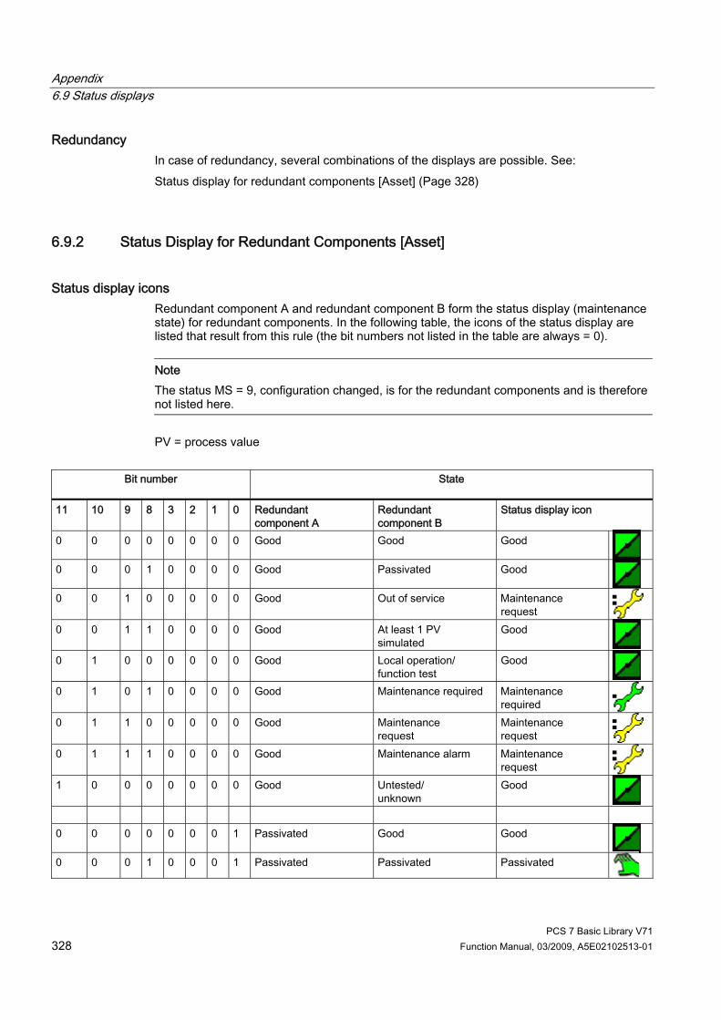
Appendix 6.9 Status displays
PCS 7 Basic Library V71 328 Function Manual, 03/2009, A5E02102513-01
Redundancy In case of redundancy, several combinations of the displays are possible. See: Status display for redundant components [Asset] (Page 328)
6.9.2 Status Display for Redundant Components [Asset]
Status display icons Redundant component A and redundant component B form the status display (maintenance state) for redundant components. In the following table, the icons of the status display are listed that result from this rule (the bit numbers not listed in the table are always = 0).
Note The status MS = 9, configuration changed, is for the redundant components and is therefore not listed here.
PV = process value
Bit number
State
11 10 9 8 3 2 1 0 Redundant component A
Redundant component B
Status display icon
0 0 0 0 0 0 0 0 Good Good Good
0 0 0 1 0 0 0 0 Good Passivated Good
0 0 1 0 0 0 0 0 Good Out of service Maintenance request
0 0 1 1 0 0 0 0 Good At least 1 PV simulated
Good
0 1 0 0 0 0 0 0 Good Local operation/ function test
Good
0 1 0 1 0 0 0 0 Good Maintenance required Maintenance required
0 1 1 0 0 0 0 0 Good Maintenance request
Maintenance request
0 1 1 1 0 0 0 0 Good Maintenance alarm Maintenance request
1 0 0 0 0 0 0 0 Good Untested/ unknown
Good
0 0 0 0 0 0 0 1 Passivated Good Good
0 0 0 1 0 0 0 1 Passivated Passivated Passivated

Appendix 6.9 Status displays
PCS 7 Basic Library V71 Function Manual, 03/2009, A5E02102513-01 329
Bit number
State
0 0 1 0 0 0 0 1 Passivated Out of service Out of service
0 0 1 1 0 0 0 1 Passivated At least 1 PV simulated
At least 1 PV simulated
0 1 0 0 0 0 0 1 Passivated Local operation/ function test
Local operation/ function test
0 1 0 1 0 0 0 1 Passivated Maintenance required Maintenance required
0 1 1 0 0 0 0 1 Passivated Maintenance request
Maintenance request
0 1 1 1 0 0 0 1 Passivated Maintenance alarm Maintenance alarm
1 0 0 0 0 0 0 1 Passivated Untested/ unknown
Passivated
0 0 0 0 0 0 1 0 Out of service Good Maintenance
request 0 0 0 1 0 0 1 0 Out of service Passivated Out of service
0 0 1 0 0 0 1 0 Out of service Out of service Out of service
0 0 1 1 0 0 1 0 Out of service At least 1 PV
simulated At least 1 PV simulated
0 1 0 0 0 0 1 0 Out of service Local operation/ function test
Local operation/ function test
0 1 0 1 0 0 1 0 Out of service Maintenance required Maintenance required
0 1 1 0 0 0 1 0 Out of service Maintenance request
Maintenance request
0 1 1 1 0 0 1 0 Out of service Maintenance alarm Maintenance alarm
1 0 0 0 0 0 1 0 Out of service Untested/ unknown
Out of service
0 0 0 0 0 0 1 1 At least 1 PV simulated Good Good
0 0 0 1 0 0 1 1 At least 1 PV simulated Passivated At least 1 PV
simulated 0 0 1 0 0 0 1 1 At least 1 PV simulated Out of service At least 1 PV
simulated 0 0 1 1 0 0 1 1 At least 1 PV simulated At least 1 PV
simulated At least 1 PV simulated
0 1 0 0 0 0 1 1 At least 1 PV simulated Local operation/ function test
Local operation/ function test
0 1 0 1 0 0 1 1 At least 1 PV simulated Maintenance required Maintenance required

Appendix 6.9 Status displays
PCS 7 Basic Library V71 330 Function Manual, 03/2009, A5E02102513-01
Bit number
State
0 1 1 0 0 0 1 1 At least 1 PV simulated Maintenance request
Maintenance request
0 1 1 1 0 0 1 1 At least 1 PV simulated Maintenance alarm Maintenance alarm
1 0 0 0 0 0 1 1 At least 1 PV simulated Untested/ unknown
At least 1 PV simulated
0 0 0 0 0 1 0 0 Local operation/
function test Good Good
0 0 0 1 0 1 0 0 Local operation/
function test Passivated Local operation/
function test 0 0 1 0 0 1 0 0 Local operation/
function test Out of service Local operation/
function test 0 0 1 1 0 1 0 0 Local operation/
function test At least 1 PV simulated
Local operation/ function test
0 1 0 0 0 1 0 0 Local operation/ function test
Local operation/ function test
Local operation/ function test
0 1 0 1 0 1 0 0 Local operation/ function test
Maintenance required Maintenance required
0 1 1 0 0 1 0 0 Local operation/ function test
Maintenance request
Maintenance request
0 1 1 1 0 1 0 0 Local operation/ function test
Maintenance alarm Maintenance alarm
1 0 0 0 0 1 0 0 Local operation/ function test
Untested/ unknown
Local operation/ function test
0 0 0 0 0 1 0 1 Maintenance required Good Maintenance
required 0 0 0 1 0 1 0 1 Maintenance required Passivated Maintenance
required 0 0 1 0 0 1 0 1 Maintenance required Out of service Maintenance
required 0 0 1 1 0 1 0 1 Maintenance required At least 1 PV
simulated Maintenance required
0 1 0 0 0 1 0 1 Maintenance required Local operation/ function test
Maintenance required
0 1 0 1 0 1 0 1 Maintenance required Maintenance required Maintenance required
0 1 1 0 0 1 0 1 Maintenance required Maintenance request
Maintenance request
0 1 1 1 0 1 0 1 Maintenance required Maintenance alarm Maintenance alarm
1 0 0 0 0 1 0 1 Maintenance required Untested/ unknown
Maintenance required

Appendix 6.9 Status displays
PCS 7 Basic Library V71 Function Manual, 03/2009, A5E02102513-01 331
Bit number
State
0 0 0 0 0 1 1 0 Maintenance request
Good Maintenance request
0 0 0 1 0 1 1 0 Maintenance request
Passivated Maintenance request
0 0 1 0 0 1 1 0 Maintenance request
Out of service Maintenance request
0 0 1 1 0 1 1 0 Maintenance request
At least 1 PV simulated
Maintenance request
0 1 0 0 0 1 1 0 Maintenance request
Local operation/ function test
Maintenance request
0 1 0 1 0 1 1 0 Maintenance request
Maintenance required Maintenance request
0 1 1 0 0 1 1 0 Maintenance request
Maintenance request
Maintenance request
0 1 1 1 0 1 1 0 Maintenance request
Maintenance request
Maintenance alarm
1 0 0 0 0 1 1 0 Maintenance request
Untested/ unknown
Maintenance request
0 0 0 0 0 1 1 1 Maintenance alarm Good Maintenance
request 0 0 0 1 0 1 1 1 Maintenance alarm Passivated Maintenance alarm
0 0 1 0 0 1 1 1 Maintenance alarm Out of service Maintenance alarm
0 0 1 1 0 1 1 1 Maintenance alarm At least 1 PV
simulated Maintenance alarm
0 1 0 0 0 1 1 1 Maintenance alarm Local operation/
function test Maintenance alarm
0 1 0 1 0 1 1 1 Maintenance alarm Maintenance required Maintenance alarm
0 1 1 0 0 1 1 1 Maintenance alarm Maintenance
request Maintenance alarm
0 1 1 1 0 1 1 1 Maintenance alarm Maintenance alarm Maintenance alarm
1 0 0 0 0 1 1 1 Maintenance alarm Untested/
unknown Maintenance alarm
1 0 0 0 1 0 0 0 Untested/
unknown Untested/ unknown
Untested/ unknown
0 0 0 0 1 0 0 0 Untested/ unknown
Good Good
0 0 0 1 1 0 0 0 Untested/ unknown
Passivated Passivated
0 0 1 0 1 0 0 0 Untested/ unknown
Out of service Out of service

Appendix 6.9 Status displays
PCS 7 Basic Library V71 332 Function Manual, 03/2009, A5E02102513-01
Bit number
State
0 0 1 1 1 0 0 0 Untested/ unknown
At least 1 PV simulated
At least 1 PV simulated
0 1 0 0 1 0 0 0 Untested/ unknown
Local operation/ function test
Local operation/ function test
0 1 0 1 1 0 0 0 Untested/ unknown
Maintenance required Maintenance required
0 1 1 0 1 0 0 0 Untested/ unknown
Maintenance request
Maintenance request
0 1 1 1 1 0 0 0 Untested/ unknown
Maintenance alarm Maintenance alarm

Appendix 6.9 Status displays
PCS 7 Basic Library V71 Function Manual, 03/2009, A5E02102513-01 333
6.9.3 PA-Field-Device Status and Diagnostic Information
PA-Field-Device Status PA Status Limits (Bit 1 + 0 irrelevant)
Meaning of PA Status Message Coding MS
Quality (bit 7 + 6)
Substatus (bits 5 – 2)
M = Message Q = Must be acknowledged
10 0000 Good 0 10 0001 Good, configuration change made M 0 10 0010 Good, active warning 0 10 0011 Good, active interrupt 0 10 0100 Good, unacknowledged configuration change 0 10 0101 Good, unacknowledged warning 0 10 0110 Good, unacknowledged interrupt 0 10 1000 Good, device switches to fail-safe position M 0 10 1001 Good, maintenance required
(more diagnostic data available) Q 5
10 1010 Good, maintenance request pending (more diagnostic data available)
Q 6
10 1111 Good, self-test completed 0 01 0000 Uncertain, not specified Q 6 01 0001 Uncertain, last valid value Q 7 01 0010 Uncertain, substitute value Q 7 01 0011 Uncertain, initial value 0 01 0100 Uncertain, measured value generation incorrect Q 6 01 0101 Uncertain, value outside defined range Q 6 01 0110 Uncertain, signal source uncertain Q 6 01 0111 Uncertain, configuration error Q 6 01 1000 Uncertain, measured value simulated Q 3 01 1001 Uncertain, sensor calibration Q 6 01 1010 Uncertain, maintenance request
(more diagnostic data available) Q 6
01 1100 Uncertain, simulation started M 3 01 1101 Uncertain, simulation ended M 0 01 1110 Uncertain, process-related, no maintenance M 0 00 0000 Bad, not specified Q 7 00 0001 Bad, configuration error Q 7 00 0010 Bad, not connected Q 7 00 0011 Bad, device error Q 7 00 0100 Bad, sensor error Q 7 00 0101 Bad, no connection - last valid value Q 7 00 0110 Bad, no connection - no valid value Q 7

Appendix 6.9 Status displays
PCS 7 Basic Library V71 334 Function Manual, 03/2009, A5E02102513-01
PA Status Limits (Bit 1 + 0 irrelevant)
Meaning of PA Status Message Coding MS
00 0111 Bad, device out of service Q 2 00 1000 Bad, device out of service
(no diagnostic data, passivated) M 1
00 1001 Bad, maintenance alarm (more diagnostic data available)
Q 7
00 1010 Bad, process-related, no maintenance M 0 00 1111 Bad, local operator control/function test M 4
You will find further information about status icons for the maintenance status (MS) in the "Maintenance status MS" section.
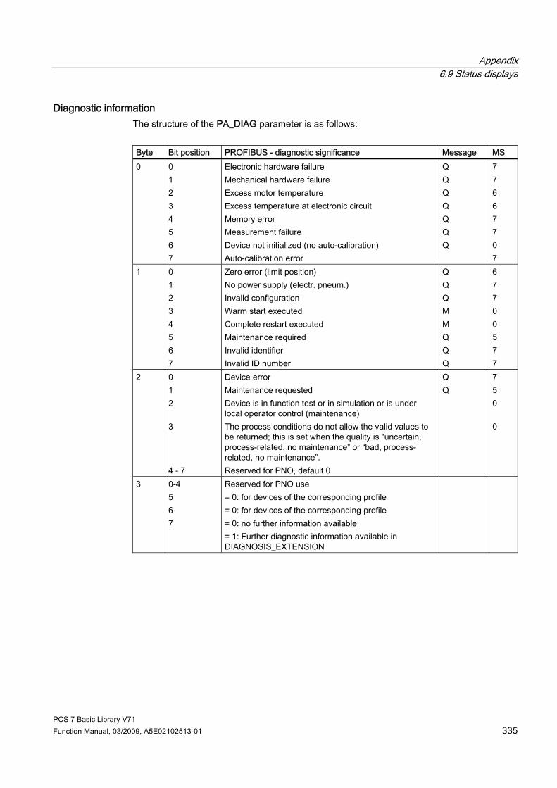
Appendix 6.9 Status displays
PCS 7 Basic Library V71 Function Manual, 03/2009, A5E02102513-01 335
Diagnostic information The structure of the PA_DIAG parameter is as follows: Byte Bit position PROFIBUS - diagnostic significance Message MS 0 0
1 2 3 4 5 6 7
Electronic hardware failure Mechanical hardware failure Excess motor temperature Excess temperature at electronic circuit Memory error Measurement failure Device not initialized (no auto-calibration) Auto-calibration error
Q Q Q Q Q Q Q
7 7 6 6 7 7 0 7
1 0 1 2 3 4 5 6 7
Zero error (limit position) No power supply (electr. pneum.) Invalid configuration Warm start executed Complete restart executed Maintenance required Invalid identifier Invalid ID number
Q Q Q M M Q Q Q
6 7 7 0 0 5 7 7
2 0 1 2 3 4 - 7
Device error Maintenance requested Device is in function test or in simulation or is under local operator control (maintenance) The process conditions do not allow the valid values to be returned; this is set when the quality is “uncertain, process-related, no maintenance” or “bad, process-related, no maintenance”. Reserved for PNO, default 0
Q Q
7 5 0 0
3 0-4 5 6 7
Reserved for PNO use = 0: for devices of the corresponding profile = 0: for devices of the corresponding profile = 0: no further information available = 1: Further diagnostic information available in DIAGNOSIS_EXTENSION

Appendix 6.10 Text libraries
PCS 7 Basic Library V71 336 Function Manual, 03/2009, A5E02102513-01
6.10 Text libraries
6.10.1 Text Library for MOD_PAL0, MOD_PAX0 The following table lists the text-library message texts and their numbers for the blocks MOD_PAL0 (FB99) and MOD_PAX0 (FB112): Text no. Message text 1 Warm restart 2 Cold restart 3 PA field device diagnostics 4 Memory error
6.10.2 Text Library for PADP_L00, PADP_L01, PADP_L02 The following table lists the text-library message texts and their numbers for the blocks PADP_L00 (FB 109), PADP_L01 (FB 110), PADP_L02 (FB 111): Text No. Message Text 1 Module error 2 Wrong module 3 Module missing
6.10.3 Text Library for DREP, DREP_L The following table lists the text-library message texts and their numbers for the blocks DREP (FB 113) and DREP_L (FB 125): Text No. Message Text 1 Failure 2 Diagnostics
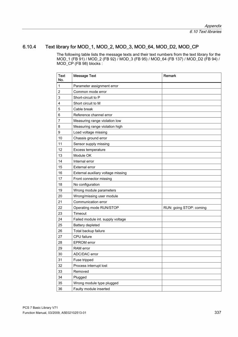
Appendix 6.10 Text libraries
PCS 7 Basic Library V71 Function Manual, 03/2009, A5E02102513-01 337
6.10.4 Text library for MOD_1, MOD_2, MOD_3, MOD_64, MOD_D2, MOD_CP The following table lists the message texts and their text numbers from the text library for the MOD_1 (FB 91) / MOD_2 (FB 92) / MOD_3 (FB 95) / MOD_64 (FB 137) / MOD_D2 (FB 94) / MOD_CP (FB 98) blocks : Text No.
Message Text Remark
1 Parameter assignment error 2 Common mode error 3 Short-circuit to P 4 Short circuit to M 5 Cable break 6 Reference channel error 7 Measuring range violation low 8 Measuring range violation high 9 Load voltage missing 10 Chassis ground error 11 Sensor supply missing 12 Excess temperature 13 Module OK 14 Internal error 15 External error 16 External auxiliary voltage missing 17 Front connector missing 18 No configuration 19 Wrong module parameters 20 Wrong/missing user module 21 Communication error 22 Operating mode RUN/STOP RUN: going STOP: coming 23 Timeout 24 Failed module int. supply voltage 25 Battery depleted 26 Total backup failure 27 CPU failure 28 EPROM error 29 RAM error 30 ADC/DAC error 31 Fuse tripped 32 Process interrupt lost 33 Removed 34 Plugged 35 Wrong module type plugged 36 Faulty module inserted

Appendix 6.10 Text libraries
PCS 7 Basic Library V71 338 Function Manual, 03/2009, A5E02102513-01
Text No.
Message Text Remark
37 Module inserted (parameter error) 38 Chatter error 39 Changeover contact diagnostics 40 CIR parameter assignment 41 CIR parameter assignment not successful

Appendix 6.10 Text libraries
PCS 7 Basic Library V71 Function Manual, 03/2009, A5E02102513-01 339
6.10.5 Text Library for MOD_D1 The following table lists the text-library message texts and their numbers for the block MOD_D1 (FB 93): Text No.
Message Text Remark
1 Parameter assignment error 2 Common mode error 3 Short-circuit to P 4 Short circuit to M 5 Cable break 6 Reference channel error 7 Measuring range violation low 8 Measuring range violation high 9 Load voltage missing 10 Chassis ground error 11 Sensor supply missing 12 Excess temperature 13 Module OK 14 Internal error 15 External error 16 External auxiliary voltage missing 17 Front connector missing 18 No configuration 19 Wrong module parameters 20 Wrong/missing user module 21 Communication error 22 Operating mode RUN/STOP RUN: going STOP: coming 23 Timeout 24 Failed module int. supply voltage 25 Battery depleted 26 Total backup failure 27 CPU failure 28 EPROM error 29 RAM error 30 ADC/DAC error 31 Fuse tripped 32 Process interrupt lost 33 Removed 34 Plugged 35 Wrong module type plugged 36 Faulty module inserted 37 Module inserted (parameter error)

Appendix 6.10 Text libraries
PCS 7 Basic Library V71 340 Function Manual, 03/2009, A5E02102513-01
Text No.
Message Text Remark
38 Chatter error 39 Changeover contact diagnostics 40 Sensor or load voltage loss 41 Faulty fuse 42 AI error hardware 43 AI wire break 44 AI below measuring range 45 AI above measuring range 46 AO wire break 47 AO short-circuit 48 CIR parameter assignment 49 CIR parameter assignment not successful 50 Signal A faulty 51 Signal B faulty 52 Signal N faulty 53 Faulty value supplied to the channels 54 Sensor supply 5.2 V/8.2 V faulty 55 Sensor supply 24 V faulty 56 Namur sensor signal line error 57 Readback error 58 Power supply 1: Error 59 Power supply 2: Error 60 Actuator OFF

Appendix 6.10 Text libraries
PCS 7 Basic Library V71 Function Manual, 03/2009, A5E02102513-01 341
6.10.6 Text library for MOD_D3 The following table lists the text library message texts and their numbers for the block MOD_D3 (FB134): Text no.
Message text Remark
1 Parameter assignment error 2 Common mode error 3 Short-circuit to P 4 Short circuit to M 5 Cable break 6 Reference channel error 7 Measuring range violation low 8 Measuring range violation high 9 Load voltage missing 10 Chassis ground error 11 Sensor supply missing 12 Excess temperature 13 Module OK 14 Internal error 15 External error 16 External auxiliary voltage missing 17 Front connector missing 18 No configuration 19 Wrong module parameters 20 Wrong/missing user module 21 Communication error 22 Operating mode RUN/STOP RUN: going STOP: coming 23 Timeout 24 Failed module int. supply voltage 25 Battery depleted 26 Total backup failure 27 CPU failure 28 EPROM error 29 RAM error 30 ADC/DAC error 31 Fuse tripped 32 Process interrupt lost 33 Removed 34 Plugged 35 Wrong module type plugged 36 Faulty module inserted 37 Module inserted (parameter assignment error)

Appendix 6.10 Text libraries
PCS 7 Basic Library V71 342 Function Manual, 03/2009, A5E02102513-01
Text no.
Message text Remark
38 Chatter error 39 Changeover contact diagnostics 40 Sensor or load voltage loss 41 Faulty fuse 42 AI error hardware 43 AI wire break 44 AI below measuring range 45 AI above measuring range 46 AO wire break 47 AO short-circuit 48 CIR parameter assignment 49 CIR parameter assignment not successful 50 Signal A faulty 51 Signal B faulty 52 Signal N faulty 53 Faulty value supplied to the channels 54 Sensor supply 5.2 V/8.2 V faulty 55 Sensor supply 24 V faulty 56 Namur sensor signal line error 57 Readback error 58 Power supply 1: Error 59 Power supply 2: Error 60 Actuator OFF 61 Undervoltage 62 Overvoltage 63 Overload 64 Reserve 65 Hardware interrupt 66 Actuator warning 67 Safety shutdown 68 Ambiguous error 69 Error 1 in actuator/sensor 70 Error 2 in actuator/sensor 71 Channel temporarily not available
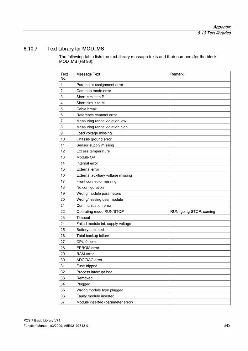
Appendix 6.10 Text libraries
PCS 7 Basic Library V71 Function Manual, 03/2009, A5E02102513-01 343
6.10.7 Text Library for MOD_MS The following table lists the text-library message texts and their numbers for the block MOD_MS (FB 96): Text No.
Message Text Remark
1 Parameter assignment error 2 Common mode error 3 Short-circuit to P 4 Short circuit to M 5 Cable break 6 Reference channel error 7 Measuring range violation low 8 Measuring range violation high 9 Load voltage missing 10 Chassis ground error 11 Sensor supply missing 12 Excess temperature 13 Module OK 14 Internal error 15 External error 16 External auxiliary voltage missing 17 Front connector missing 18 No configuration 19 Wrong module parameters 20 Wrong/missing user module 21 Communication error 22 Operating mode RUN/STOP RUN: going STOP: coming 23 Timeout 24 Failed module int. supply voltage 25 Battery depleted 26 Total backup failure 27 CPU failure 28 EPROM error 29 RAM error 30 ADC/DAC error 31 Fuse tripped 32 Process interrupt lost 33 Removed 34 Plugged 35 Wrong module type plugged 36 Faulty module inserted 37 Module inserted (parameter error)

Appendix 6.10 Text libraries
PCS 7 Basic Library V71 344 Function Manual, 03/2009, A5E02102513-01
Text No.
Message Text Remark
38 Chatter error 39 Changeover contact diagnostics 40 Sensor or load voltage loss 41 Faulty fuse 42 Undervoltage 43 Overvoltage 44 Actuator warning 45 Actuator OFF 46 Emergency OFF 47 Unknown error 48 Short-circuit 49 Error 50 CIR parameter assignment 51 CIR parameter assignment not successful
6.10.8 Text Library for OB_BEGIN The following table lists the text-library message texts and their numbers for the block OB_BEGIN (FB 100): Text No. Message Text Remark 1 Nested stack error Error code B#16#71: 2 Master control relay stack error Error code B#16#72: 3 Max. nesting depth for synchronous errors exceeded Error code B#16#73 4 U-stack nesting depth exceeded Error code B#16#74 5 B-stack nesting depth exceeded Error code B#16#75 6 Local data allocation error Error code B#16#76 7 Unknown opcode Error code B#16#78 8 Code length error Error code B#16#7A

PCS 7 Basic Library V71 Function Manual, 03/2009, A5E02102513-01 345
Index
A Addressing, 323
B Block icons, 284
Asset Management, 284 OB_BEGIN, 281
C ChkREAL, 279
Description, 279 CONEC, 19, 22
Description, 19 I/Os, 22
Coordination of FMCS_PID/FMT_PID, 15 CPU_RT, 25, 31
Description, 25 I/Os, 31
D Description
OR_32_TS, 203 Description of
OB_BEGIN, 183 Description of, 19, 25, 43, 47, 51, 59, 67, 80, 87, 94, 101, 107, 114, 119, 129, 150, 160, 169, 176
CONEC, 19 CPU_RT, 25 DIAG_AB, 33 DPAY_V0, 36 DPAY_V1, 43 DPDIAGV0, 47 DREP, 51 DREP_L, 59 FM_CNT, 67 FM_CO, 15 IMDRV_TS, 73 MOD_1, 80 MOD_2, 87 MOD_3, 94 MOD_4, 101
MOD_64, 107 MOD_CP, 114 MOD_D1, 119, 139 MOD_D2, 129 MOD_HA, 150 MOD_MS, 160 MOD_PAL0, 169 MOD_PAX0, 176
Description of, 194 Description of
OB_DIAG1, 194 Description of, 201 Description of
OB_END, 201 Description of
OR_HA16C, 207 Description of, 215 Description of
OR_M_16C, 215 Description of
OR_M_32C, 220 Description of, 227 Description of
OR_M_8C, 227 Description of
PADP_L00, 234 Description of, 234 Description of
PADP_L01, 240 Description of, 240 Description of
PADP_L02, 245 Description of, 245 Description of, 251 Description of
PADP_L10, 251 Description of, 258 Description of
PO_UPDAT, 258 Description of, 259 Description of
PS, 259 Description of, 264 Description of
RACK, 264 Description of
RED_F, 270 Description of, 273

Index
PCS 7 Basic Library V71 346 Function Manual, 03/2009, A5E02102513-01
Description of SUBNET, 273
Description of ChkREAL, 279
Description of QC_CHNG, 279
DIAG_AB Description, 33 I/Os, 35
DPAY V1, 46 I/Os, 46
DPAY_V0, 41 Description, 36 I/O, 41
DPAY_V1, 43 Description, 43
DPDIAGV0, 47, 50 Description, 47 I/Os, 50
DREP, 51, 56 Description, 51 I/Os, 56
DREP_L, 59, 64 Description, 59 I/Os, 64
E Error Information of Output Parameter MSG_STAT, 322
F Faceplate, 292
OB_BEGIN, 292 Faceplates, 286
Asset Management, 286 FM_CNT, 67, 71
Description, 67 I/Os, 71
FM_CO Description, 15 I/Os, 17
G General information about the block description, 9 Global representations and views of asset faceplates, 305
I I/Os of
IMDRV_TS, 78 I/Os of, 22, 31, 41, 46, 50, 56, 64, 71
CONEC, 22 CPU_RT, 31 DIAG_AB, 35 DPAY V1, 46 DPAY_V0, 41 DPDIAGV0, 50 DREP, 56 DREP_L, 64 FM_CNT, 71 FM_CO, 17
I/Os of MOD_2, 84
I/Os of MOD_1, 84
I/Os of, 84 I/Os of
MOD_2, 91 I/Os of
MOD_1, 91 I/Os of, 91 I/Os of, 98 I/Os of
MOD_3, 98 I/Os of
MOD_4, 105 I/Os of, 105 I/Os of, 111 I/Os of
MOD_64, 111 I/Os of, 117 I/Os of
MOD_CP, 117 I/Os of
MOD_D2, 125 I/Os of
MOD_D1, 125 I/Os of, 125 I/Os of
MOD_D2, 135 I/Os of
MOD_D1, 135 I/Os of, 135 I/Os of
MOD_D3, 146 I/Os of, 157 I/Os of
MOD_HA, 157 I/Os of, 165

Index
PCS 7 Basic Library V71 Function Manual, 03/2009, A5E02102513-01 347
I/Os of MOD_MS, 165
I/Os of, 172 I/Os of
MOD_PAL0, 172 I/Os of, 179 I/Os of
MOD_PAX0, 179 I/Os of
OB_BEGIN, 188 I/Os of, 188 I/Os of, 198 I/Os of
OB_DIAG1, 198 I/Os of
OB_END, 202 I/Os of, 202 I/Os of
OR_32_TS, 205 I/Os of
OR_M_16C, 210 I/Os of
OR_M_8C, 210 I/Os of
OR_HA16C, 210 I/Os of
OR_M_32C, 210 I/Os of
OR_M_16C, 216 I/Os of
OR_M_8C, 216 I/Os of
OR_HA16C, 216 I/Os of
OR_M_32C, 216 I/Os of
OR_M_16C, 221 I/Os of
OR_M_8C, 221 I/Os of
OR_HA16C, 221 I/Os of
OR_M_32C, 221 I/Os of
OR_M_16C, 230 I/Os of
OR_M_8C, 230 I/Os of
OR_HA16C, 230 I/Os of
OR_M_32C, 230 I/Os of
PADP_L00/L01/L02, 238 I/Os of, 238 I/Os of, 257 I/Os of
PADP_L10, 257 I/Os of, 262 I/Os of
PS, 262 I/Os of, 268 I/Os of
RACK, 268 I/Os of
RED_F, 272 I/Os of
SUBNET, 277 I/Os of, 277 Ident view [asset], 300 IMDRV_TS
Description, 73 I/Os, 78 Message texts, 79
Individual Views of the IPC Faceplate [Asset], 290 Individual Views of the PDM Faceplate [Asset], 287
M Maintenance Status of MS, 326 Maintenance View [Asset], 297 Message classes, 324 Message texts of
IMDRV_TS, 79 Message View [Asset], 299 MOD_1, 80, 84, 91, 337
Description, 80 I/Os, 84, 91 Text library, 337
MOD_2, 84, 87, 91, 337 Description, 87 I/Os, 84, 91 Text library, 337
MOD_3, 94, 98, 337 Description, 94 I/Os, 98 Text library, 337
MOD_4, 101, 105 Description, 101 I/Os, 105
MOD_64, 107, 111, 337 Description, 107 I/Os, 111 Text library, 337

Index
PCS 7 Basic Library V71 348 Function Manual, 03/2009, A5E02102513-01
MOD_CP, 114, 117, 337 Description, 114 I/Os, 117 Text library, 337
MOD_D1, 119, 125, 135, 339 Description, 119 I/Os, 125, 135 Text library, 339
MOD_D2, 125, 129, 135, 337 Description, 129 I/Os, 125, 135 Text library, 337
MOD_D3 Description, 139 I/Os, 146 Text library, 341
MOD_HA, 150, 157 Description, 150 I/O, 157
MOD_MS, 160, 165, 343 Description, 160 I/Os, 165 Text library, 343
MOD_PAL0, 169, 172, 336 Description, 169 I/Os, 172 Text library, 336
MOD_PAX0, 176, 179, 336 Description, 176 I/Os, 179 Text library, 336
MODE, 313 MODE settings for PA devices, 320 MODE Settings for SM Modules, 313 MS, 284 MSG_STAT, 322
O OB_BEGIN
Description, 183 OB_BEGIN, 188 OB_BEGIN
I/O, 188 OB_BEGIN, 193 OB_BEGIN
Operating and monitoring, 193 OB_BEGIN
Faceplate, 292 OB_BEGIN, 292 OB_BEGIN
Text library, 344
OB_BEGIN, 344 OB_DIAG1, 194, 198
Description, 194 I/Os, 198
OB_END, 201, 202 Description, 201 I/Os, 202
OMODE settings for SM modules, 312 Operating and monitoring, 193
OB_BEGIN, 193 OR_32_TS
Description, 203 I/Os, 205
OR_HA16C Description, 207 I/Os, 210, 216, 221, 230
OR_M_16C, 215 Description, 215 I/Os, 210, 216, 221, 230
OR_M_32C Description, 220 I/Os, 210, 216, 221, 230
OR_M_8C, 227 Description, 227 I/Os, 210, 216, 221, 230
P PA field device status and diagnostics information, 333 PA_MODE
Settings, 320 PADP_L00, 234, 336
Description, 234 Text library, 336
PADP_L00/L01/L02, 238 I/O, 238
PADP_L01, 240, 336 Description, 240 Text library, 336
PADP_L02, 245, 336 Description, 245 Text library, 336
PADP_L10, 251, 257 Description, 251 I/Os, 257
PO_UPDAT, 258 Description, 258
PS, 259, 262 Description, 259 I/Os, 262

Index
PCS 7 Basic Library V71 Function Manual, 03/2009, A5E02102513-01 349
Q QC_CHNG, 279
Description, 279
R RACK, 264, 268
Description, 264 I/Os, 268
RED_F Description, 270 I/Os, 272
S Status display for redundant components [asset], 328 SUBNET, 273, 277
Description, 273 I/Os, 277
T Technical specifications
Blocks in the basic library, 309 Text library for
MOD_D3, 341 MOD_PAX0, 336
Text library for, 336 Text library for
MOD_PAL0, 336 Text library for, 336 Text library for
PADP_L00, 336 Text library for
PADP_L01, 336 Text library for
PADP_L02, 336 Text library for
DREP, 336 Text library for
DREP_L, 336 Text library for, 336 Text library for
MOD_64, 337 Text library for, 337 Text library for
MOD_D2, 337 Text library for
MOD_CP, 337 Text library for
MOD_3, 337 Text library for
MOD_2, 337 Text library for
MOD_1, 337 Text library for
MOD_D1, 339 Text library for, 339 Text library for, 343 Text library for
MOD_MS, 343 Text library for
OB_BEGIN, 344 Text library for, 344

Index
PCS 7 Basic Library V71 350 Function Manual, 03/2009, A5E02102513-01