PCI overview - CISL · PCI intro • Peripheral component interface (PCI) bus developed by Intel...
33
PCI overview EECS E4340 Spring, 2004
Transcript of PCI overview - CISL · PCI intro • Peripheral component interface (PCI) bus developed by Intel...
PCI overview
EECS E4340Spring, 2004
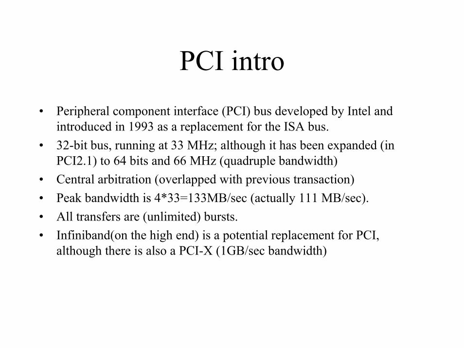
PCI intro• Peripheral component interface (PCI) bus developed by Intel and
introduced in 1993 as a replacement for the ISA bus.• 32-bit bus, running at 33 MHz; although it has been expanded (in
PCI2.1) to 64 bits and 66 MHz (quadruple bandwidth)• Central arbitration (overlapped with previous transaction)• Peak bandwidth is 4*33=133MB/sec (actually 111 MB/sec).• All transfers are (unlimited) bursts.• Infiniband(on the high end) is a potential replacement for PCI,
although there is also a PCI-X (1GB/sec bandwidth)
Intel system design
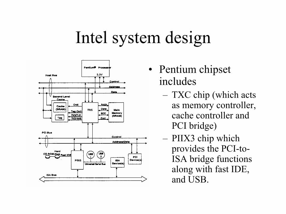
• Pentium chipset includes – TXC chip (which acts
as memory controller, cache controller and PCI bridge)
– PIIX3 chip which provides the PCI-to-ISA bridge functions along with fast IDE, and USB.
Giving commands to I/O devices• Two methods to address the device
– Special I/O instructions– Memory-mapped I/O
• x86 has both (the PDP/8 only has the former). x86 really has special I/O instructions as a legacy matter.
• Special I/O instructions specify both a device address and a command word
• Memory-mapped I/O:– Portions of the address space assigned to I/O device– Reads and writes to those addresses are interpreted as commands to the
I/O device– User programs are presed from issuing I/O operations directly by the OS.
I/O address space protected by address translation.

OS and I/O• OS needs to know when
– I/O device has completed an operation– I/O device has encountered an error
• This can be done in two ways– Polling
• Simple!• I/O device put information in status register• OS periodically checks the status register• Busy wait loop not an efficient way to use the CPU unless the device is really
fast.• I/O checks can be dispersed amount computation-intensive code
– I/O interrupt• Special hardware needed to cause an interrupt (I/O device) and detect an
interrupt (process) and save the proper states to resume after the interrupt (processor)
I/O interrupt
• I/O interrupt is like an exception except that it is asynchronous with respect to instruction execution– I/O interrupt not associated with any instruction– I/O interrupt does not prevent any instruction from
completing
• I/O interrupts more complicated than exceptions– Need to convey the identity of the device generating the
interrupts– Interrupt request can have different urgency/priority.
OS and I/O (more)
• The OS is the interface between the user program and the I/O hardware
• I/O shared by multiple programs using the processor
• Interrupts handled by OS => cause transfer to supervisor mode
• Low-level control of an I/O device is very complex => managing concurrent events
• Provide protection to shared I/O resources• Provide equitable access to shared I/O resources
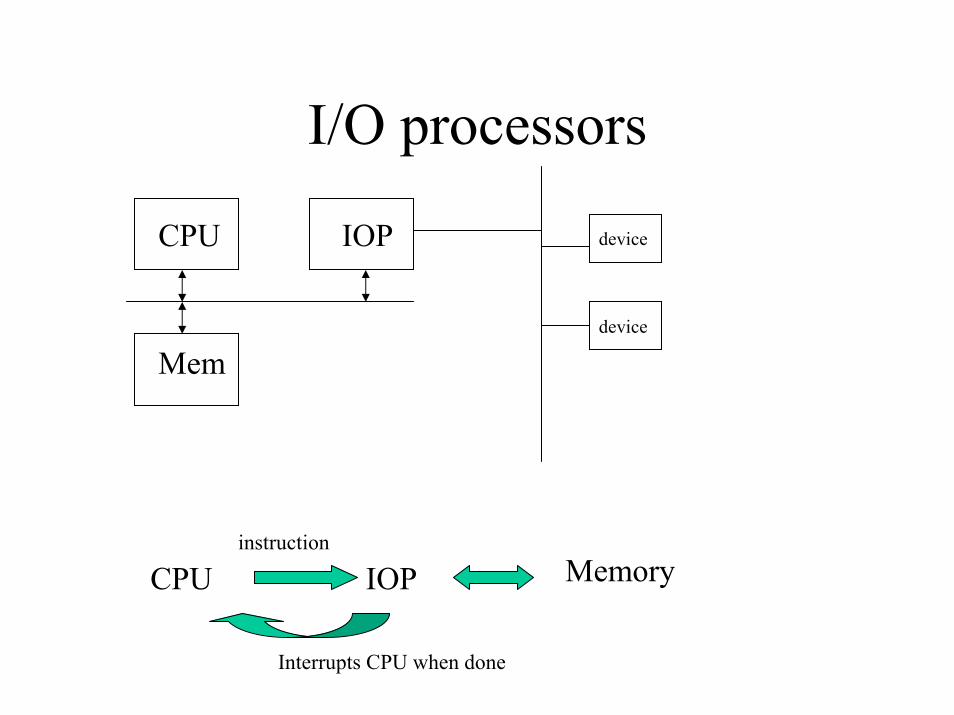
I/O processors
CPU IOP
Mem
device
device
instructionMemoryCPU IOP
Interrupts CPU when done
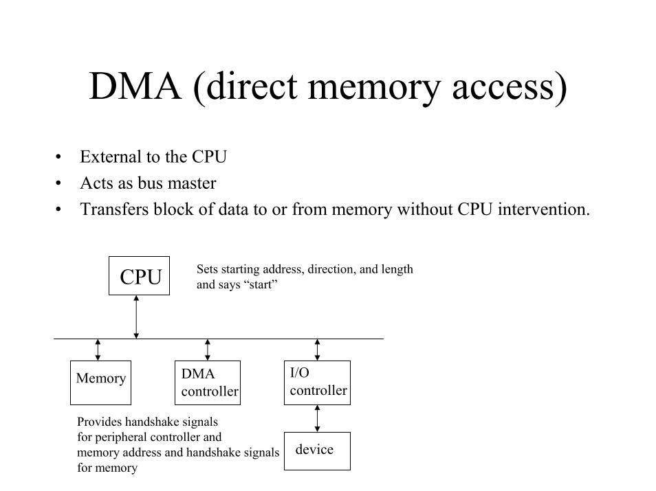
DMA (direct memory access)• External to the CPU• Acts as bus master• Transfers block of data to or from memory without CPU intervention.
CPU Sets starting address, direction, and lengthand says “start”
Memory DMAcontroller
I/O controller
Provides handshake signalsfor peripheral controller and memory address and handshake signalsfor memory
device
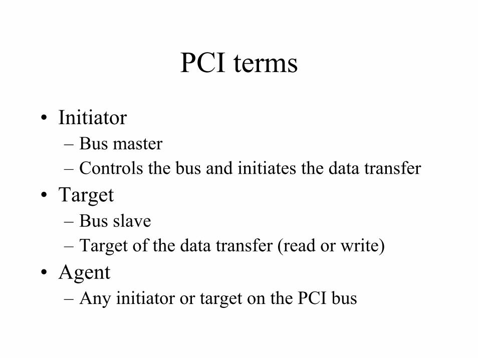
PCI terms
• Initiator– Bus master– Controls the bus and initiates the data transfer
• Target– Bus slave– Target of the data transfer (read or write)
• Agent– Any initiator or target on the PCI bus
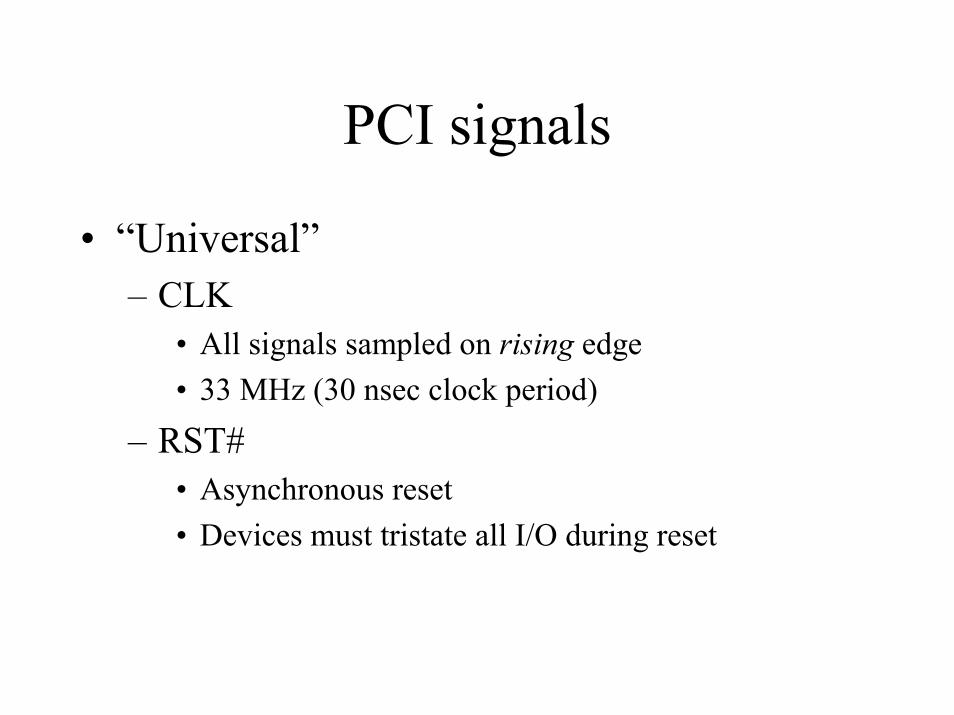
PCI signals
• “Universal”– CLK
• All signals sampled on rising edge• 33 MHz (30 nsec clock period)
– RST#• Asynchronous reset• Devices must tristate all I/O during reset
PCI signals
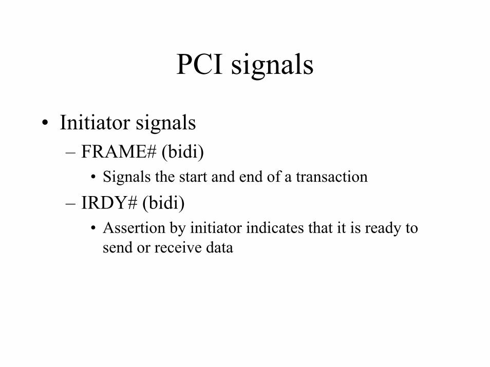
• Initiator signals– FRAME# (bidi)
• Signals the start and end of a transaction
– IRDY# (bidi)• Assertion by initiator indicates that it is ready to
send or receive data
PCI signals
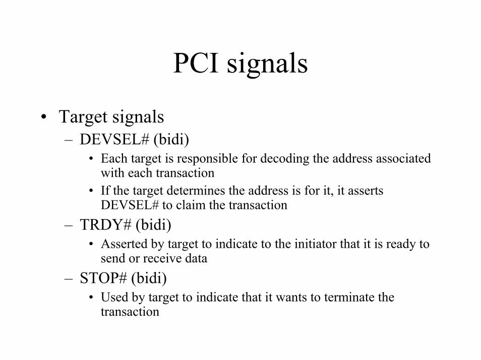
• Target signals– DEVSEL# (bidi)
• Each target is responsible for decoding the address associated with each transaction
• If the target determines the address is for it, it asserts DEVSEL# to claim the transaction
– TRDY# (bidi)• Asserted by target to indicate to the initiator that it is ready to
send or receive data– STOP# (bidi)
• Used by target to indicate that it wants to terminate the transaction
PCI signals
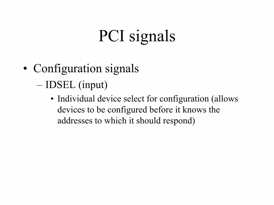
• Configuration signals– IDSEL (input)
• Individual device select for configuration (allows devices to be configured before it knows the addresses to which it should respond)
PCI signals
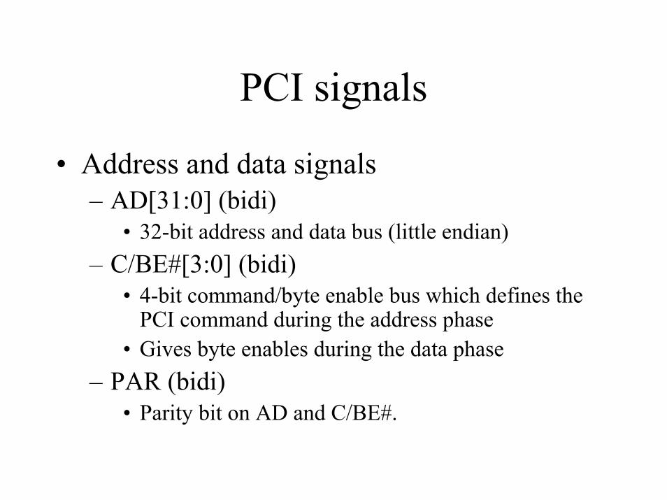
• Address and data signals– AD[31:0] (bidi)
• 32-bit address and data bus (little endian)– C/BE#[3:0] (bidi)
• 4-bit command/byte enable bus which defines the PCI command during the address phase
• Gives byte enables during the data phase– PAR (bidi)
• Parity bit on AD and C/BE#.
PCI signals
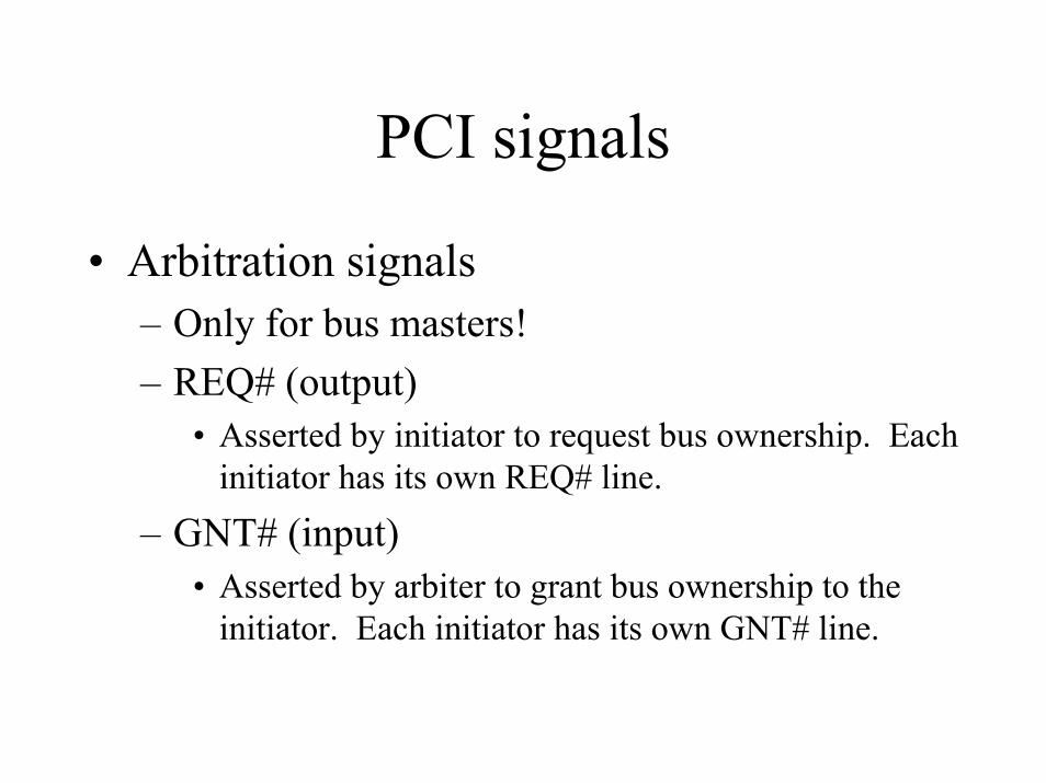
• Arbitration signals– Only for bus masters!– REQ# (output)
• Asserted by initiator to request bus ownership. Each initiator has its own REQ# line.
– GNT# (input)• Asserted by arbiter to grant bus ownership to the
initiator. Each initiator has its own GNT# line.
PCI signals
• Error signals– PERR# (bidi)
• Indicates data parity error
– SERR# (bidi)• Indicates a system error has occurred.
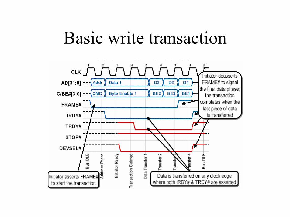
Basic write transaction
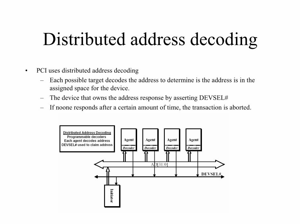
Distributed address decoding• PCI uses distributed address decoding
– Each possible target decodes the address to determine is the address is in the assigned space for the device.
– The device that owns the address response by asserting DEVSEL#– If noone responds after a certain amount of time, the transaction is aborted.
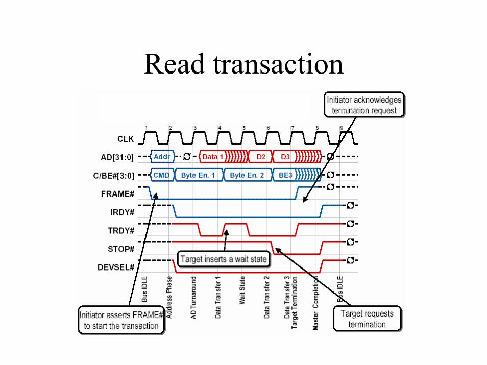
Read transaction
Read transaction comments
• Both the target (by deasserting TRDY#) or initiator (by deasserting IRDY#) can insert a wait state (a bus cycle in which no data transfer occurs)
• Either agent can also terminate the transaction– Target by asserting STOP#– Initiator by deasserting FRAME#
PCI Address Space
• Three types of address space– Configuration space
• Stores basic information about device• Allows OS or BIOS to program a device
– I/O space• Used with basic PC peripherals (legacy)
– Memory space• Everything else
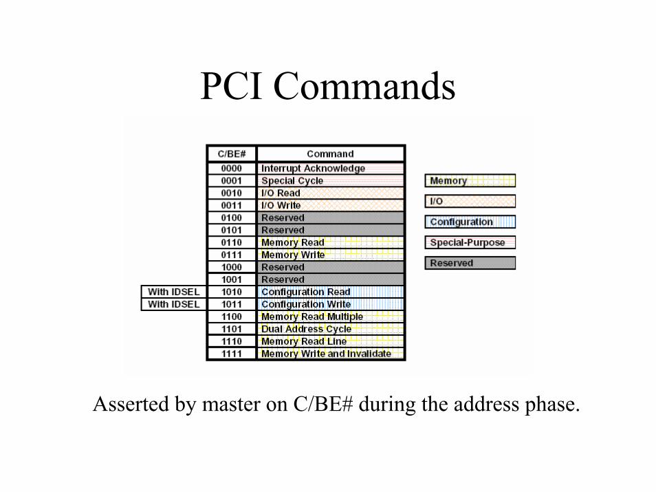
PCI Commands
Asserted by master on C/BE# during the address phase.
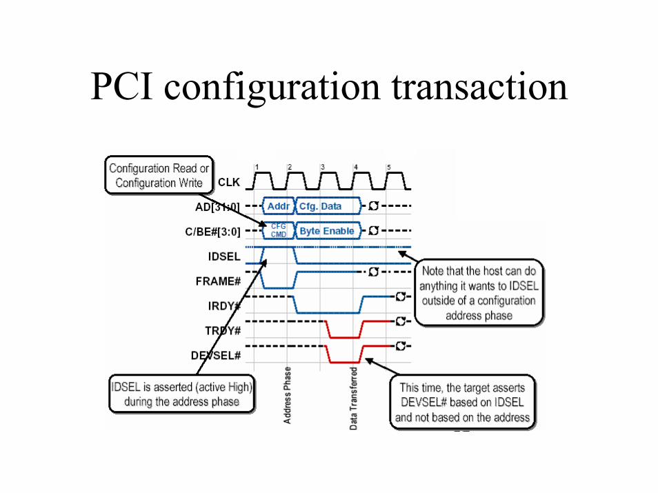
PCI configuration transaction
PCI configuration comments
• Generated by host or PCI-to-PCI bridge• Add-in cards contains basic information for
the BIOS or OS– Type of card and device– Interrupt requirements– Address-space requirements
• Use dedicated IDSEL to address device• For plug-and-play capability
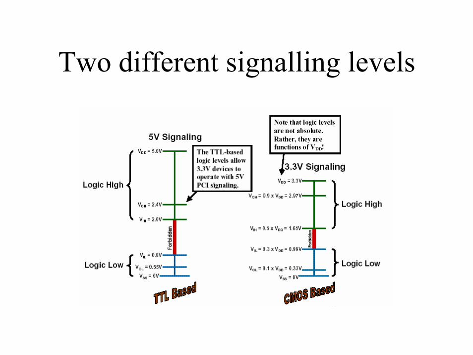
Two different signalling levels
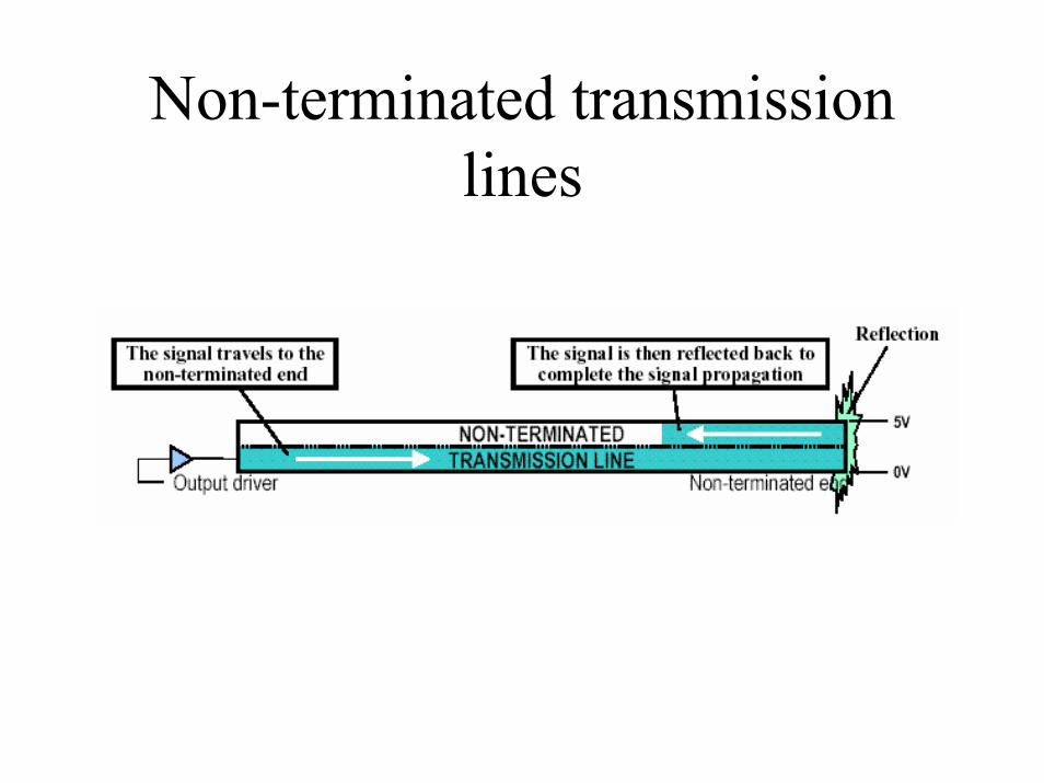
Non-terminated transmission lines

Diode clamps
• Prevent momentary short circuits due to tristatedelays.
• In 5-V environment, only diode clamp to ground is required.
• In 3.3-V environment, both clamps are required. 5 V must be used in a “mixed environment.
Strict electrical requirements for add-in cards
• Clock trace must be exactly 2.5”• One pin per signal with max input cap of 10 pF.• 32-bit PCI signals must be no more than 1.5”.• 64-bit PCI signals must be no more than 2.0”
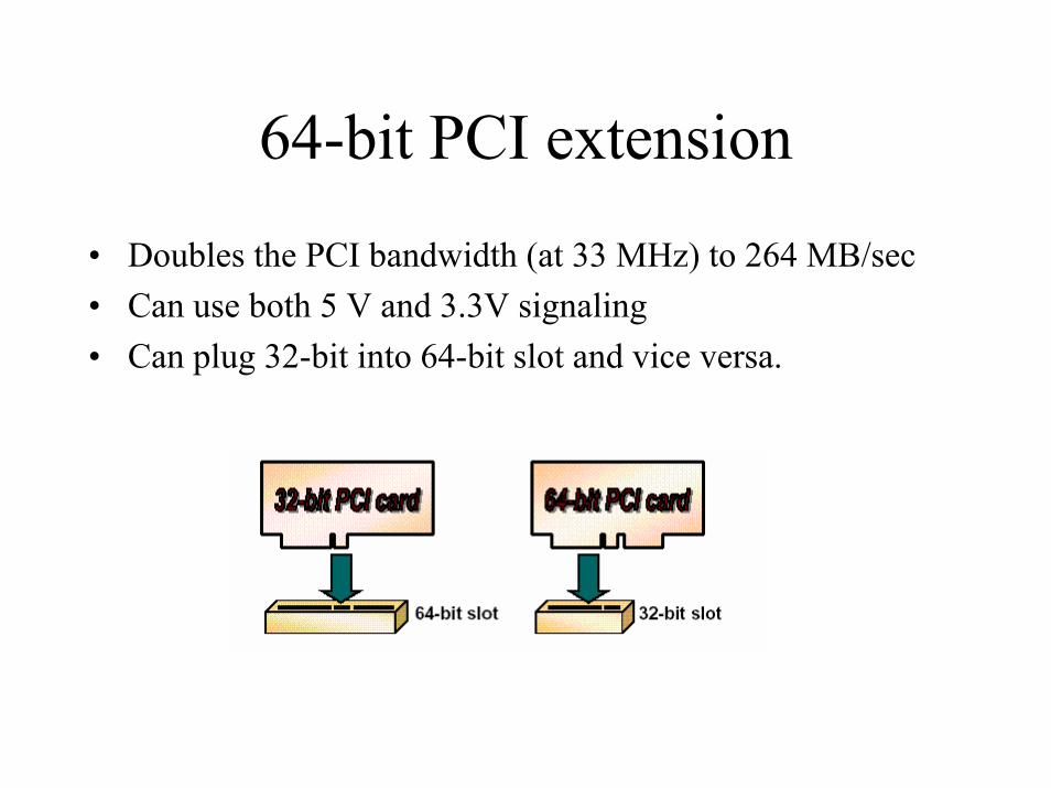
64-bit PCI extension
• Doubles the PCI bandwidth (at 33 MHz) to 264 MB/sec• Can use both 5 V and 3.3V signaling• Can plug 32-bit into 64-bit slot and vice versa.
Extra pins for 64-bit• AD[63:32]
– Additional data/address bits• C/BE#[7:4]
– Additional byte enables (not generally used for additional PCI commands)• PAR64
– Parity of the these additional bits• REQ64#
– Like FRAME#, but indicates that the initiator wants a 64-bit transaction• ACK64#
– Like DEVSEL#, but indicates that the target that it can do 64-bit
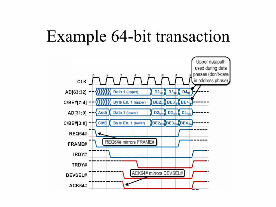
Example 64-bit transaction
66 MHz PCI
• PCI bandwidth can be pushed to 528 MB/sec
• Usually used with 64-bit extension, but can also have 32-bit 66-MHz PCI
• Signally protocol the same as 33 MHz PCI, but 66 MHz PCI only uses 3.3 V signalling
• Loading allowance cut in half