PCA-6653 Video Display Card for Flat Panel and...
34
PCA-6653 Video Display Card for Flat Panel and CRT
Transcript of PCA-6653 Video Display Card for Flat Panel and...

PCA-6653Video Display Card forFlat Panel and CRT

ii
Copyright Notice
This document is copyrighted by Advantech Co., Ltd. All rightsare reserved. Advantech Co., Ltd., reserves the right to makeimprovements to the products described in this manual at any timewithout notice.
No part of this manual may be reproduced, copied, translated, ortransmitted in any form or by any means without the prior writtenpermission of Advantech Co., Ltd. Information provided in thismanual is intended to be accurate and reliable. However, Advan-tech Co., Ltd., assumes no responsibility for its use, nor for anyinfringements upon the rights of third parties which may resultfrom its use.
All brand and product names mentioned herein are trademarks orregistered trademarks of their respective holders.
Part No. 2002665300, 1st EditionPrinted in Taiwan, September 1995

iii
Contents
Chapter 1 Introduction ..................................1Description .............................................................................. 2Specifications .......................................................................... 3Display Support ...................................................................... 4Video BIOS ............................................................................. 4Simultaneous Display Mode .................................................. 5
Chapter 2 Hardware Setup ...........................7Hardware Configuration ....................................................... 8Connectors ............................................................................ 10Jumper Setting ..................................................................... 11Pin Assignments ................................................................... 12Power Management ............................................................. 13
Chapter 3 Software Drivers and Utilities...15Simultaneous Display Mode ................................................ 16Sleep Mode............................................................................ 16Software Support ................................................................. 17Driver Installation................................................................ 18Windows Setup ............................................................................... 19AutoCAD R12 ................................................................................. 22Lotus 1-2-3 and Lotus Symphony ................................................. 24VESA ............................................................................................... 26Word ................................................................................................ 27WordPerfect .................................................................................... 28

iv

Chapter 1 Introduction 1
1Introduction
CH
AP
TE
R

2 PCA-6653 User's Manual
DescriptionThe PCA-6653 is based on the CHIPS VGA flat panel/CRT controllerand is fully IBM VGA compatible. This controller offers a large set ofextended functions and higher resolutions, and it supports simulta-neous functioning. Since the PCA-6653 VGA adapter is fully compat-ible, you do not require any special drivers to operate in standardmodes. The enclosed software drivers allow you to take advantage ofthe extended features of the PCA-6653:
High performance in Microsoft Windows
Resolutions up to 1024x768 in graphics modes with 256 colors
640x480 resolution in graphics modes with 32K, 64K, and 16Mcolors
132 column text mode
Warning! Be sure to turn off the power and unplug all compo-nents before attempting to install or adjust the PCA-6653. Make sure the jumpers are set correctly beforeconnecting the PCA-6653 to your flat panel display.Incorrect jumper settings could damage your display.

Chapter 1 Introduction 3
SpecificationsChipset: CHIPS 65545, integrated flat panel / CRT VGA controllerSlot: High performance 16-bit ISA-bus add-on cardBIOS: 27C010, supports 4 banks, 32KB for each bankMemory: 1MB DRAM on board
256Kx16 DRAM socket for frame buffer (Optional)Windows GUI (Graphic User Interface) Accelerator:
32-bit BitBLT EngineHardware Cursor
Wait State: 32-bit Memory read/write operationZero wait state (when CPU write to 66545)
Simultaneous CRT/LCD display: Available with TFT, STN, B/W, EL,CRT
Display support: CRT - 1024x768 Non-interlaced analog or multi-synch monitors with 256 colors640x480 CRT and Panel display with 64K colorsFlat panel - TFT LCD (Max resolution is 1024x768)
DSTN /STN LCD (Max resolution is 800x600)B/W LCDPLASMA LCDEL
Connector: DB-44 for Flat panel DisplayDB-15 for CRTBuilt-in 44-pin for general purpose connector (Pin Header)Built-in 5-pin for keyboard connection (Housing)
Power: On-board DC-DC converter supplies LCD bias voltage (VEE)Power Management: Chips 65545 power saving stand-by mode

4 PCA-6653 User's Manual
Driver SupportThe software driver provides:
Microsoft Windows 3.XX
MS DOS
AutoCAD Release 12
Lotus 1-2-3
Lotus Symphony
VESA
Microsoft Word
WordPerfect
132 Column Text Mode (only usable in WordPerfect and Wordstar)
The PCA-6653 provides 16.7M colors with a CRT output frequencyof 65 MHz.
Video BIOSThe standard BIOS chip supports four kinds of flat panel displays:
TFT LCD: Toshiba LTM09C016
DSTN LCD: Sharp LM64183P
MONO LCD: Sharp LM64C142
EL: Planar EL640.480AD4

Chapter 1 Introduction 5
Simultaneous Display ModeThe PCA-6653 supports simultaneous display to a CRT monitor and aflat panel display. The flat panel may be TFT, mono, DSTN, or EL.
If you use a DSTN LCD in this mode, the display must be under 16/256 colors or the CRT and flat panel screens will tremble. You mustadd a frame buffer with 512K RAM and update the BIOS setup. Callus for assistance.

6 PCA-6653 User's Manual

Chapter 2 Hardware Setup 7
2Hardware Setup
CH
AP
TE
R

8 PCA-6653 User's Manual
Hardware ConfigurationThe PCA-6653 is based on chipset 65545 and has high performance, asimple configuration, and fully supported LCD/EL/CRT.
Address
Data
Control
16
24
16-bitISA BUS
32 16
RGBH/V Sync
1MB VideoMemory
512KBFrame Buffer
24Panel Data
Panel Control
DC-DCConverter
/ENVEEPower-on
Sequencing
+VEE
-VEE
To CRT Display
To Flat Panel Display
+V -V
65540/45
PCA-6653 System block diagramAddress
Data BIOS
Figure 2-1 Block Diagram
Chapter 2 Hardware Setup 9
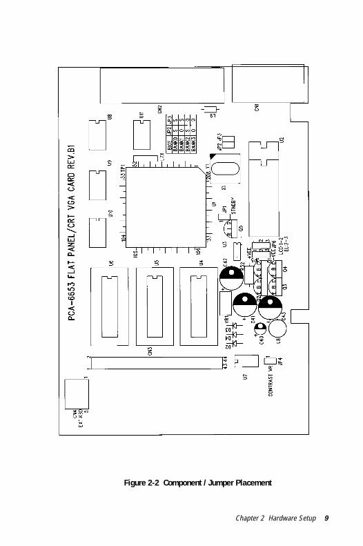
Figure 2-2 Component / Jumper Placement

10 PCA-6653 User's Manual
ConnectorsCN1 DB-15 Female for CRT monitor
CN2 DB-44 Female for flat panel display
CN3 pin-header 44-pin for flat panel display (pin to pincompatible with CN2)
CN4 housing 5-pin for keyboard connection

Chapter 2 Hardware Setup 11
Jumper SettingBe sure the jumper setting is correct before you install the card to thechassis. Refer to figure 2-2 for pin assignments.
JP1 2 PIN 1: standby mode to save power , 0: normal mode
JP4 2 PIN External Contrast Adjustment VR connector
JP5 3 PIN VEE for LCDs power source selection1-2 : +VEE (output is positive)2-3 : -VEE (output is negative)
JP6 3 PIN Panel Colock polarity select (SHFCLK)1-2 : +SHFCLK (for LCDs)2-3 : -SHFCLK (for EL)
JP2,JP3 2 PIN ROM BIOS Bank select
BANK JP2 JP3 LCD ModelBank 0 1 1 LTM09C016Bank 1 0 1 LM64C142Bank 2 1 0 LM64183PBank 3 0 0 EL640.480AD4
VR1: VEE adjustment for LCD/ELStep 1 - Short the JP4.Step 2 - Adjust the voltage for each LCD VEE. Voltage ranges from +12V to +40V
Note: The two jumper settings are 0 (open) and 1 (closed).
Warning! Turn off the system power, and disconnect thecables prior to adjusting the voltage!
Adjusting the VR1 may damage the LCD/ELdisplay module. Call if you need assistance.

12 PCA-6653 User's Manual
Pin AssignmentsCN1:
Pin No. Descriptions Pin No. Descriptions1 R 9 (Not used)2 G 10 Ground3 B 11 (Not used)4 (Not used) 12 (Not used)5 Ground 13 Horizontal sync6 Ground 14 Vertical sync7 Ground 15 (Not used)8 Ground
CN2 and CN3:Pin No. Descriptions Pin No. Descriptions1 +12V 23 P142 +12V 24 P153 Ground 25 P164 Ground 26 P175 +5V 27 P186 +5V 28 P197 VEESAFE 29 P208 Ground 30 P219 P0 31 P2210 P1 32 P2311 P2 33 Ground12 P3 34 Ground13 P4 35 ASHFCLK14 P5 36 FLM15 P6 37 M16 P7 38 LP17 P8 39 Ground18 P9 40 ENABKL19 P10 41 KB_DATA20 P11 42 KB_CLK21 P12 43 C_VR122 P13 44 C_VR2

Chapter 2 Hardware Setup 13
CN4:Pin No. Descriptions1 Clock2 Data3 (Not used)4 Ground5 +5V
Power ManagementTo save power, you can disable the Chips 65545 by setting the JP1jumper to 1 (closed). This clears the memory and interrupts input andoutput. You can use the included software if you only want to stopoutput. To disable the flat panel's backlight, set CN2-pin40 (EN-ABKL) to 0 (open).

14 PCA-6653 User's Manual

Chapter 3 Software Drivers and Utilities 15
3Software Drivers andUtilities
CH
AP
TE
R

16 PCA-6653 User's Manual
This chapter describes the installation and operation of the softwaredrivers on the included Display Driver diskette.
Simultaneous Display ModeThe 65545 VGA BIOS supports monochrome LCD, EL, color TFTand STN LCD flat panel displays. It also supports interlaced and non-interlaced analog monitors (VGA color and VGA monochrome) inhigh-resolution modes while maintaining complete IBM VGAcompatibility. Digital monitors (i.e. MDA, CGA, and EGA) are NOTsupported. Multiple frequency (multisync) monitors are supported asanalog monitors.
Both CRT and panel displays can be used simultaneously. The PCA-6653 can be set in one of three configurations: on a CRT, on a flatpanel display, or on both simultaneously. The system is initially set tosimultaneous display mode. In the utility diskette, there are three.COM files which can be used to select the display. Simply type thefilename at the DOS prompt:
CT.COM Enables CRT display only
FP.COM Enables panel display only
SM.COM Enables both displays at the same time.
Sleep ModeThe Display Driver diskette contains two files that support sleepmode. Simply type the filename at the DOS prompt:
ON.COM switches to normal display mode.
OFF.COM switches to sleep mode.

Chapter 3 Software Drivers and Utilities 17
Software SupportThe drivers support the following applications using the filenames andresolutions listed:
Application Filename Resolution ColorsWindows 3.1 LINEAR4.DRV 640x480 16
800x600 161024x768 16
LINEAR8.DRV 640x480 256800x600 2561024x768 256
LINEAR15.DRV 640x480 32KLINEAR16.DRV 640x480 64KLINEAR24.DRV 640x480 16M
AutoCAD R12 RCTURBOC.EXP 640x480 16800x600 161024x768 16640x480 256800x600 2561024x768 256640x480 32K640x480 64K640x480 16M
Lotus 1-2-3 2.0 and Lotus Symphony 1.0,1.1V132X25.DRV 132x25 (Text) 16V132X50.DRV 132x50 (Text) 16
VESA 1.2 VESA.COM 800x600 161024x768 16640x400 256640x480 256800x600 2561024x768 256640x480 32K640x480 64K
Word 5.0 VGA600.VID 800x600 16VGA768.VID 1024x768 16
Word 5.5 VGA55600.VID 800x600 16VGA55768.VID 1024x768 16

18 PCA-6653 User's Manual
WordPerfect 5.0 CHIPS600.WPD 800x600 16CHIPS768.WPD 1024x768 16
WordPerfect 5.1 VGA600.VRS 800x600 16VGA768.VRS 1024x768 16
Driver Installation
Necessary prerequisitesThe instructions in this manual assume that you understand elementa-ry concepts of MS-DOS and the IBM Personal Computer. Before youattempt to install any driver or utility you should: know how to copyfiles from a floppy disk to a directory on the hard disk, understand theMS-DOS directory structure, and know how to format a floppy disk.If you are uncertain about any of these concepts, please refer to theDOS or Windows user reference guides for more information beforeyou proceed with the installation.
Before you beginBefore you begin installing software drivers, you should make abackup copy of the Display Driver diskette, and store the original in asafe place. The Display Driver diskette contains drivers for severalversions of certain applications. You must install the correct versionin order for the driver to work properly so make sure you know whichversion of the application you have.

Chapter 3 Software Drivers and Utilities 19
Windows Setup
These drivers are designed to work with Microsoft Windows 3.1. Youmay install these drivers through Windows or in DOS.
Step 1: Install Windows as you normally would for a VGA display.Run Windows to make sure that it is working correctly.
Step 2: Place the Display Driver diskette in drive A. In WindowsProgram Manager, choose File from the Options Menu. Then fromthe pull-down menu, choose Run . . . . At the command line prompt,type A:\WINSETUP . Press the <ENTER> key or click OK to beginthe installation. At this point the setup program locates the directorywhere Windows is installed. For proper operation, the drivers must beinstalled in the Windows subdirectory. Press <ENTER> to completethe installation. Once completed, the Display Driver Control Panelappears on the screen. This Control Panel allows you to select andload the installed drivers.
Another method of installing these drivers is through the File Manag-er. Click on Drive A:. Then double-click on WINSETUP.EXE tobegin installation.
Changing Display Drivers in WindowsTo change display drivers in Windows, select the Windows Setup iconfrom the Main window. You will be shown the current setup configu-ration. Select Change System Settings from the Option menu. Clickon the arrow at the end of the Display line. You will be shown a list ofdisplay drivers. Click on the driver you want. Then click on the OKbutton. Follow the directions to complete the setup.
Changing Color SchemesAfter you change display drivers, you may notice that the colorscheme used by Windows looks strange. This is because differentdrivers have different default colors. To change the color scheme,select the Control Panel from the Main window. Select the Coloricon. You will be shown the current color scheme. Choose a newcolor scheme and click the OK button.

20 PCA-6653 User's Manual
DOS SetupStep 1: Install Windows as you normally would for a VGA display.Run Windows to make sure that it is working correctly. Then exitWindows.
Step 2: Place the Display Driver diskette in drive A. Type A: <EN-TER> to make this the default drive. Type SETUP <ENTER> to runthe driver SETUP program. Press any key to get to the applicationslist. Using the arrow keys, select Windows Version 3.1 and press the<ENTER> key. Press the <ENTER> key to select All Resolutions,and then press <END> to begin the installation. At this point you willbe asked for the path to your Windows System directory (defaultC:\WINDOWS). When the installation is complete, press any key tocontinue. Press <ESC> followed by Y to exit to DOS.
Step 3: Change to the directory where you installed Windows (usuallyC:\WINDOWS).
Step 4: Type SETUP <ENTER> to run the Windows Setup program.It will show the current Windows configuration. Use the up arrow keyto move to the Display line and press <ENTER>. A list of displaydrivers will be shown. Use the arrow keys to select one of the driversstarting with an asterisk (*) and press <ENTER>.
Step 5: Follow the directions on the screen to complete the setup. Inmost cases, you may press <ENTER> to accept the suggested option.When Setup is done, it will return to DOS. Type WIN <ENTER> tostart Windows with the new display driver.
Changing Display Drivers in DOSTo change display drivers from DOS, change to the Windowsdirectory and run Setup, repeating steps 4 and 5 from the previouspage. Besides the special display drivers marked by an asterisk (*),you should be able to use the following standard drivers:
VGA 640x480, 16 colors
Super VGA 800x600, 16 colors

Chapter 3 Software Drivers and Utilities 21
Panning DriversSpecial panning drivers are provided to allow high-resolution modesto be displayed on a flat panel or CRT. These drivers will show asection of a larger screen and will automatically pan, or scroll, thescreen horizontally and vertically when the mouse reaches the edge ofthe display.
Linear Acceleration Drivers A special high-performance linear acceleration driver is provided for256-color modes. This driver may require special hardware and maynot be supported on all systems. It is only available for Windows3.1.

22 PCA-6653 User's Manual
AutoCAD R12
These drivers are designed to work with Autodesk AutoCAD R12.They conform to the Autodesk Device Interface (ADI) for Renderingdrivers and Display drivers. These display list drivers accelerateredraw, pan, and zoom functions.
Driver installationStep 1: Place the Display Driver diskette in drive A. Type A: <EN-TER> to make this the default drive. Type SETUP <ENTER> to runthe SETUP program. Press any key to get to the applications list.Using the arrow keys, select AutoCAD Release 12 and press <EN-TER>. This will display a list of supported driver resolutions. Usingthe arrow keys and the <ENTER> key, select the resolutions that areappropriate for your monitor. When all of the desired resolutions havebeen selected, press <END> to begin the installation. At this point youwill be asked for a drive and directory to copy the driver files. Enterthe drive and directory that contains the installed AutoCAD R12. Ifthe destination directory does not exist you will be asked for confir-mation. When the installation is complete, press any key to continue.Press <ESC> followed by Y to exit to DOS.
Step 2: Go to the AutoCAD directory where the new drivers wereinstalled and run the driver installation program by typing ACAD12 -r <ENTER>. This program will configure your AutoCAD R12 to usethe new display drivers. Select TurboDLD Classic.
Configuring TurboDLDSelect Configure Video Display. In Display Device Configurationchoose Select Graphics Board/Resolution. Then choose SelectDisplay Graphics Board. After choosing a graphics board, go toSelect Display Resolution. After selecting the display resolution, savethe new configuration, and return to the main menu.
Basic Configuration MenuThis menu allows you to modify:
Number of AutoCAD Command Lines

Chapter 3 Software Drivers and Utilities 23
Font Size 6x8/8x8/8x14/8x16/12x20/12x24
Dual Screen Enable/Disable
User Interface Configuration
Double Click Interval Time
BP Button
BP Highlight Patt Line/Xor Rect/Both
BP Refresh Enable/Disable
BP Cache Enable/Disable
Expert Configuration MenuThis menu allows you to modify:
Display List Enable/Disable
Drawing Cache Enable/Disable
Use Acad 31 bit space? Yes/No
Internal Command Echo Enable/Disable
BP Zoom Mode Freeze/Float
Regen Mode Incremental/Fast
If your previously installed driver is not TurboDLD, you will have toreconfigure the RENDER command the first time you use it.

24 PCA-6653 User's Manual
Lotus 1-2-3 and Lotus Symphony
These drivers are designed to work with Lotus 1-2-3 versions 2.0,2.01 and 2.2, and with Lotus Symphony versions 1.0 and 1.1.
Driver installationStep 1: Place the Display Driver diskette into drive A. Make A thedefault drive by typing A: <ENTER>. Run the SETUP program bytyping SETUP <ENTER>. Press any key to display a list of supportedapplications. Use the arrow keys to select Lotus/Symphony, and press<ENTER>. A list of supported screen resolutions will be displayed.Use the arrow keys to select the desired screen resolution and press<ENTER>. (Make sure your monitor is able to display the resolutiondesired) Press <END> to begin the driver installation process. Adefault drive and directory path will be displayed. Use the backspacekey to erase this default and type in the 123 directory. At this pointyou may be asked to create the target directory if it does not alreadyexist. After the files have been installed, press any key to return to thelist of supported applications. Press <ESC> followed by Y to exit toDOS. Copy all the files that were just created in the temporarydirectory onto a formatted floppy diskette.
Step 2: Go to your 123 directory, and start the installation program.Type the following commands:
C: <ENTER>
INSTALL <ENTER>
Step 3: The Lotus installation program will load and present theinstallation menu. From this menu, select Advanced Options. Fromthe Advanced Options menu, select Add New Drivers To Library.From the Add New Drivers Menu, select Modify Current Driver Set.From the Modify Driver Set Menu, select Text Display. From the TextDisplay menu, select one of drivers.
Step 4: After the selection of the appropriate VGA display driver, youwill need to exit this menu and return to the Main Lotus InstallationMenu. Do this by selecting Return To Menu.
Step 5: At the Main Lotus Installation Menu, select Save Changes.

Chapter 3 Software Drivers and Utilities 25
Step 6: At this point the Installation Menu will prompt you for thename of your new Lotus configuration file. The Lotus system willprompt you with the default value — 123.SET, but you may want touse a filename that indicates the resolution of its driver. For example,if you installed the 132 column by 25 line driver, you could name thisdriver 132X25.SET, or if you installed the 80 by 50 driver, you maywant to call the file 80X50.SET.
Step 7: The installation of your Lotus 1-2-3 driver is now complete.You will need to exit the Lotus installation program at this point. Atthe main Lotus Installation Menu, select Exit.
NOTE: If your driver set is not 123.SET, you have to type thefilename of your driver set in the command line when you start Lotus1-2-3. For example, if you named your driver set 132X25.SET, typethe following to start Lotus 1-2-3:
123 132X25.SET <ENTER>

26 PCA-6653 User's Manual
VESA
The Video Electronics Standards Association (VESA) has created astandard for a Super VGA BIOS Extension (VBE). This defines astandard software interface to allow application programs to set andcontrol extended video modes, such as 800x600 graphics, on videoadapters from different manufacturers.
The VESA driver adds this Super VGA BIOS Extension to the VGABIOS. Any application program which supports the VESA standarddriver interface can be used with this driver. This VESA driverconforms to the VESA Super VGA Standard #VS891001.
Driver installationStep 1: Place the Display Driver diskette into drive A. Make A thedefault drive by typing A: <ENTER>. Run the SETUP program bytyping SETUP <ENTER>. Press any key to display a list of supportedapplications. Use the arrow keys to select VESA Driver Version 1.2and press <ENTER>. Press the <ENTER> key to select All Resolu-tions, and press <END> to begin the installation. A default drive anddirectory path will be displayed. Use the backspace key to erase thisand type in a directory that is in the directory path (such as C:\BIN orC:\UTILS). After the files have been installed, press any key to returnto the list of supported applications. Press <ESC> followed by Y toexit to DOS.
Step 2: To install the VESA driver, type either VESA <ENTER> orVESA + <ENTER> at the DOS prompt. The optional + command lineparameter enables all of the available modes. Make sure that yourmonitor is capable of displaying these high resolution modes beforeenabling them.
NOTE: If the video BIOS already supports VBE extended videomodes, DO NOT use this driver. Run the VTEST.EXE program to seeif the video BIOS supports the VBE modes.

Chapter 3 Software Drivers and Utilities 27
Word
These drivers are designed to work with Microsoft Word 5.0 and 5.5.
Driver installationIf you have already installed Word on your computer, go to Step 2 toinstall the new video driver.
Step 1: Install Word as normal.
Step 2: After you complete the Word installation, place the DisplayDriver diskette into drive A. Make A the default drive by typing A:<ENTER>. Run the SETUP program by typing SETUP <ENTER>.Press any key to display a list of supported applications. Use thearrow keys to select Word and press <ENTER>. Use the arrow keysto select the desired screen resolution and press <ENTER> (make sureyour monitor is able to display the resolution desired). Press <END>to begin the driver installation process. A default drive and directorypath will be displayed. Use the backspace key to erase this and type inyour Word directory. After the files have been installed, press any keyto return to the list of supported applications. Press <ESC> followedby Y to exit to DOS.
Step 3: Copy the driver file for the desired resolution that was justinstalled to SCREEN.VID. (The driver file names are listed on pages12-13.)

28 PCA-6653 User's Manual
WordPerfect
These drivers are designed to work with WordPerfect 5.0 or 5.1. Theysupport 132-column display in editing mode, and high-resolutiongraphics display in PreView mode.
Driver installationStep 1: Place the Display Driver Diskette into drive A. Make A thedefault drive by typing A: <ENTER>. Run the SETUP program bytyping SETUP <ENTER>. Press any key to display a list of supportedapplications. Use the arrow keys to select WordPerfect and press<ENTER>. A list of supported screen resolutions will be displayed.Use the arrow keys to select the desired screen resolution and press<ENTER> (make sure your monitor is able to display the resolutiondesired). Press <END> to begin the driver installation process. Adefault drive and directory path will be displayed. Use the backspacekey to erase this default and type in the WordPerfect directory. Atthis point you may be asked to create the target directory if it does notalready exist. After the files have been installed, press any key toreturn to the list of supported applications. Press <ESC> followed byY to exit to DOS.
Step 2: Start WordPerfect, and press <SHIFT>+<F1> to enter thesetup menu. Select D for Display and G for Graphics Screen Type,and then choose the desired Chips VGA resolution.
Configuring WordPerfect 5.0 for 132 columnsFollow these instructions to configure WordPerfect 5.0 for 132column text mode:
Step 1: To use the SETCOL program to set 132 columns and 25 rows,type the following command:
SETCOL 132, 25 <ENTER>
Step 2: Start WordPerfect. The program will detect the number ofrows and columns automatically. If for some reason WordPerfect isunable to adapt to 132 columns by 25 rows, start WordPerfect withthe following command:
WP /SS=25,132 <ENTER>

Chapter 3 Software Drivers and Utilities 29
Configuring WordPerfect 5.1 for 132 columnsStart WordPerfect and press <SHIFT>+<F1> to enter the setup menu.Select D for Display and T for Text Screen Type and then selectChips 132 Column Text.

30 PCA-6653 User's Manual