PC BASED MULTI-TOUCH INTERFACE SYSTEM3... · CERTIFICATE OF APPROVAL ... PC BASED MULTI-TOUCH...
63
PC BASED MULTI-TOUCH INTERFACE SYSTEM Project submitted in partial fulfillment of requirements For the Degree of Bachelor of Engineering By Prerak H. Desai Labhesh Hase Pallav Edwankar Mihir Joshi Under the guidance of Internal Guide Prof. K. T. Talele Department of Electronics Engineering Sardar Patel Institute of Technology University of Mumbai 2009-2010
-
Upload
hoangthuan -
Category
Documents
-
view
224 -
download
0
Transcript of PC BASED MULTI-TOUCH INTERFACE SYSTEM3... · CERTIFICATE OF APPROVAL ... PC BASED MULTI-TOUCH...
PC BASED MULTI-TOUCH INTERFACE SYSTEM
Project submitted in partial fulfillment of requirements
For the Degree of
Bachelor of Engineering
ByPrerak H. DesaiLabhesh Hase
Pallav EdwankarMihir Joshi
Under the guidance of
Internal Guide
Prof. K. T. Talele
Department of Electronics EngineeringSardar Patel Institute of Technology
University of Mumbai2009-2010
Bhartiya Vidya BhavansSardar Patel Institute of Technology
Munshi Nagar, Andheri (w),Mumbai - 400 058.
2009-10
PC BASED MULTI-TOUCH INTERFACE SYSTEM
Project submitted in partial fulfillment of requirements
For the Degree of
Bachelor of Engineering
ByPrerak H. DesaiLabhesh Hase
Pallav EdwankarMihir Joshi
Under the guidance of
Internal Guide
Prof. K. T. Talele
Department of Electronics Engineering
Bhartiya Vidya BhavansSardar Patel Institute of Technology
Munshi Nagar, Andheri (w),Mumbai - 400 058.
2009-10
CERTIFICATE OF APPROVAL
This is to certify that the following students
Prerak H. DesaiLabhesh Hase
Pallav EdwankarMihir Joshi
have successfully completed and submitted the project entitled
PC BASED MULTI-TOUCH INTERFACE SYSTEM
towards the fulfillment of Bachelor of Engineering course in Electronics of theMumbai University
. . . . . . . . . . . . . . . . . . . . . . . . . . . . . . . . . . . . . . . . . . . . . . . . . . . . . .
Internal Examiner External Examiner
. . . . . . . . . . . . . . . . . . . . . . . . . . . . . . . . . . . . . . . . . . . . . . . . . . . . . . . . . . . . . . . . . . . . . . . . . .
Internal Guide Head of Department Principal
Contents
Acknowledgement . . . . . . . . . . . . . . . . . . . . . . . . . . . . . . . . . 5Abstract . . . . . . . . . . . . . . . . . . . . . . . . . . . . . . . . . . . . . . 6
1 Introduction 71.1 Brief Introduction . . . . . . . . . . . . . . . . . . . . . . . . . . . . . . . . . 71.2 Need for the Project . . . . . . . . . . . . . . . . . . . . . . . . . . . . . . . 81.3 Scope of the Project . . . . . . . . . . . . . . . . . . . . . . . . . . . . . . . 91.4 Block Diagram . . . . . . . . . . . . . . . . . . . . . . . . . . . . . . . . . . 10
2 Literature Survey 12
3 FTIR Concepts 163.1 FTIR Layers . . . . . . . . . . . . . . . . . . . . . . . . . . . . . . . . . . . . 173.2 Strength and Weaknesses . . . . . . . . . . . . . . . . . . . . . . . . . . . . . 18
4 Hardware Description 194.1 Introduction . . . . . . . . . . . . . . . . . . . . . . . . . . . . . . . . . . . . 194.2 Touch Table . . . . . . . . . . . . . . . . . . . . . . . . . . . . . . . . . . . . 20
4.2.1 Touch Screen . . . . . . . . . . . . . . . . . . . . . . . . . . . . . . . 204.2.2 IR Led Array . . . . . . . . . . . . . . . . . . . . . . . . . . . . . . . 214.2.3 IR Detection Camera . . . . . . . . . . . . . . . . . . . . . . . . . . . 22
4.3 Microcontroller-Atmega328 . . . . . . . . . . . . . . . . . . . . . . . . . . . . 234.3.1 Programming Robot Board . . . . . . . . . . . . . . . . . . . . . . . 25
4.4 XBee Communication Modules . . . . . . . . . . . . . . . . . . . . . . . . . 264.4.1 ZigBee v/s Bluetooth . . . . . . . . . . . . . . . . . . . . . . . . . . . 27
5 Software Description 295.1 Community Core Vision(CCV) . . . . . . . . . . . . . . . . . . . . . . . . . 315.2 Processing . . . . . . . . . . . . . . . . . . . . . . . . . . . . . . . . . . . . . 325.3 TUIO Protocol . . . . . . . . . . . . . . . . . . . . . . . . . . . . . . . . . . 335.4 Ardunio IDE . . . . . . . . . . . . . . . . . . . . . . . . . . . . . . . . . . . 35
6 Hardware Implementation 376.1 Touch Table . . . . . . . . . . . . . . . . . . . . . . . . . . . . . . . . . . . . 37
1
6.1.1 Construction of Touch Sensor . . . . . . . . . . . . . . . . . . . . . . 376.1.2 Construction of I.R Circuitry . . . . . . . . . . . . . . . . . . . . . . 386.1.3 Modification of Visible Light Camera . . . . . . . . . . . . . . . . . . 38
6.2 Robot Hardware . . . . . . . . . . . . . . . . . . . . . . . . . . . . . . . . . 396.2.1 Designed board . . . . . . . . . . . . . . . . . . . . . . . . . . . . . . 406.2.2 ZigBee Modules . . . . . . . . . . . . . . . . . . . . . . . . . . . . . . 40
7 Software Implementation 417.1 Libraries . . . . . . . . . . . . . . . . . . . . . . . . . . . . . . . . . . . . . . 417.2 Algorithm . . . . . . . . . . . . . . . . . . . . . . . . . . . . . . . . . . . . . 437.3 Detection of robot . . . . . . . . . . . . . . . . . . . . . . . . . . . . . . . . 43
7.3.1 Camera Marker Relationship . . . . . . . . . . . . . . . . . . . . . . . 447.3.2 Marker Recognition- Basic Principle . . . . . . . . . . . . . . . . . . 457.3.3 Marker Recognition- Program Description . . . . . . . . . . . . . . . 46
7.4 D.C. Motor Calibration . . . . . . . . . . . . . . . . . . . . . . . . . . . . . . 467.4.1 Need for using DC Motors . . . . . . . . . . . . . . . . . . . . . . . . 467.4.2 Calibration Process . . . . . . . . . . . . . . . . . . . . . . . . . . . . 47
7.5 Program Description . . . . . . . . . . . . . . . . . . . . . . . . . . . . . . . 487.6 Embedded Programming . . . . . . . . . . . . . . . . . . . . . . . . . . . . . 49
7.6.1 Programming the Microcontroller . . . . . . . . . . . . . . . . . . . . 497.6.2 Robot Programming . . . . . . . . . . . . . . . . . . . . . . . . . . . 49
8 Results and Conclusion 51
A Additional Programs and Project Pictures 55
B Designed Atmega328 board 58
Bibliography 59
2

List of Figures
1.1 Block Diagram . . . . . . . . . . . . . . . . . . . . . . . . . . . . . . . . . . 10
3.1 FTIR concept . . . . . . . . . . . . . . . . . . . . . . . . . . . . . . . . . . . 163.2 Acrylic Sheet and Compliant Surface . . . . . . . . . . . . . . . . . . . . . . 17
4.1 Touch table . . . . . . . . . . . . . . . . . . . . . . . . . . . . . . . . . . . . 204.2 IR Array in working condition. The red points indicate that IR LED is work-
ing. They are not invisible to naked eyes. . . . . . . . . . . . . . . . . . . . . 214.3 PS3Eye camera converted to IR camera . . . . . . . . . . . . . . . . . . . . . 224.4 Atmega328 microcontroller chip . . . . . . . . . . . . . . . . . . . . . . . . . 234.5 USB board used to program the microcontroller . . . . . . . . . . . . . . . . 254.6 The Zigbee modules used for wireless communication . . . . . . . . . . . . . 26
5.1 Blob detection . . . . . . . . . . . . . . . . . . . . . . . . . . . . . . . . . . . 305.2 TUIO Protocol . . . . . . . . . . . . . . . . . . . . . . . . . . . . . . . . . . 34
6.1 IR circuitry for 8 IR leds . . . . . . . . . . . . . . . . . . . . . . . . . . . . . 386.2 Camera modification process . . . . . . . . . . . . . . . . . . . . . . . . . . . 396.3 Designed microcontroller board . . . . . . . . . . . . . . . . . . . . . . . . . 40
7.1 Camera Marker Relationship . . . . . . . . . . . . . . . . . . . . . . . . . . . 447.2 Marker Recognition . . . . . . . . . . . . . . . . . . . . . . . . . . . . . . . . 45
8.1 Different markers . . . . . . . . . . . . . . . . . . . . . . . . . . . . . . . . . 518.2 Marker detection in different orientations . . . . . . . . . . . . . . . . . . . . 528.3 Difference between traced and original path . . . . . . . . . . . . . . . . . . 53
A.1 Snapshot of two different sine wave related programs . . . . . . . . . . . . . 55A.2 Snapshot of the Presentation . . . . . . . . . . . . . . . . . . . . . . . . . . . 56A.3 Snapshot of program playing with box . . . . . . . . . . . . . . . . . . . . . 56A.4 Snapshot of photo application . . . . . . . . . . . . . . . . . . . . . . . . . . 56A.5 Snapshot of the Project . . . . . . . . . . . . . . . . . . . . . . . . . . . . . 57A.6 Snapshot of Arrangement of Touch Table . . . . . . . . . . . . . . . . . . . . 57
B.1 Designed Atmega328 board . . . . . . . . . . . . . . . . . . . . . . . . . . . 58
3

List of Tables
4.1 IR led Specifications . . . . . . . . . . . . . . . . . . . . . . . . . . . . . . . 214.2 Specifications . . . . . . . . . . . . . . . . . . . . . . . . . . . . . . . . . . . 26
6.1 Hardware Components . . . . . . . . . . . . . . . . . . . . . . . . . . . . . . 37
7.1 Angle readings . . . . . . . . . . . . . . . . . . . . . . . . . . . . . . . . . . 477.2 Distance readings . . . . . . . . . . . . . . . . . . . . . . . . . . . . . . . . . 48
4

Acknowledgement
We would like to thank our internal guide, Prof K. T. Talele, for his overwhelming supportduring the entire phase of our project. His able guidance was instrumental in us achievingour goal. We would also like to thank him for providing us with the pre requisite componentsfor the project.
We would also like to thank Prof Y.S.Rao for helping us make the PCBs and extending hisknowledge of hardware electronics to us. We would also like to thank Prof S.T. Gandhe forproviding us with the college projector whenever we needed it and the staff at the workshopfor providing us with assistance related to carpentry and metal working. The project wouldnot have shaped up the way it has without the support and constructive criticism of ourprofessors that enabled us to complete our project with a high degree of competence.
We would also like to thank all the non teaching staff of Electronics division for theirinvaluable support during the duration of the project.
5

Abstract
Technology has evolved to a great extent and it promises to evolve further in the yearsto come. For instance, we have faster processors that can execute thousands of instructionwithin a second. These developments haven’t stopped and scientist, developers and compa-nies around the globe are continuously working on ways to improve the technology in everypossible way.
Apart from speed, throughput and various other aspect of a computer there is one otherimportant factor that is to be taken into account when designing a system. This aspect isthe quality of interaction that takes place between user and computer. There are variousways in which quality of interaction can to improved.
The project aims at using one such low cost interaction method, a multi touch system,to show how the interaction between human and machine can be improved. This improvedinteraction is shown by controlling a microcontroller based robot according to the touchinput given by the user.
The touch screen is not capacitive based screens that are used in the mobile phone thesedays. But the touch screen is implemented using Infra red LED and an Infra red camera.The robot is made using DC motors and a microcontroller. The feedback includes imagescaptured by the over head camera. The communication is done using wireless module thatimplements IEEE 802.15.4 Zigbee protocol. The programming is done on a Java basedplatform and C language.
This project can be used in scenarios wherein the operator has to control multiple objectssimultaneously and the environment cannot be viewed directly by the operator.
6
Chapter 1
Introduction
1.1 Brief Introduction
The traditional way of interacting with a computer is by a mouse and/or a keyboard. Weprovide the computer with inputs more or less by the use of buttons. Regardless of the inputtype, the computer can only handle one input at the time which makes the input handlingand sorting very easy. However the way we use computers today will soon change. The toolswe use today to communicate with the computer will slowly be replaced by tools which aremore comfortable and natural for the human being to interact with. One such device is theTouch Screen. The touch screen can be single touch screen or multi touch screens. Thesingle touch screens are widely used in small embedded device like mobile phones and havelimited scope to which their implementation can extend. But with multi touch screen thisis not the case, as the number as inputs are more.
A touch screen is an electronic visual output that can detect the presence and locationof a touch within the display area. The term generally refers to touch or contact to thedisplay of the device by a finger or hand. The touch screen has two main attributes. First, itenables one to interact with what is displayed directly with the hand. Secondly, it lets one doso without requiring any intermediate device. Such displays can be attaches to computers,terminals, or networks.
Touch screens emerged from corporate research labs in the second half of the 1940s. Oneof the first places where they gained some visibility was in the terminal of a computer-assisted learning terminal that came out in 1975 as part of the PLATO project . They havesubsequently become familiar in kiosk systems, such as in retail and tourist settings, on pointof sale systems, on ATMs and on PDAs where a stylus is sometimes used to manipulate theGUI and to enter data. The popularity of smart phones, PDAs, portable game consolesand many types of information appliances is driving the demand for, and the acceptance of,touch screens. Today there are many types [12] of touch screen technology available in themarket:
1. Resistive: This type of screen uses the property of increased resistance when thetouch is detected.
7

2. Surface Acoustic wave: This type of screen uses absorption of ultrasonic wavestraveling over the touch surface to detect touch.
3. Capacitive: This type of screen uses the principle of change in capacitance to detectthe touch.
4. Strain Gauge: This uses the principle of change in strain to detect the location ofthe touch.
5. Optical Imaging: This uses the reflection of IR light to detect the location of touch.
6. Acoustic Pulse Recognition: This type of screen uses more than two piezoelectrictransducers located at some positions of the screen to turn the mechanical energy of atouch (vibration) into an electronic signal.
7. Coded LCD: In this method LCD display is turned into giant camera that providesgesture based control of objects on-screen.
1.2 Need for the Project
The primary reason of doing this project is to get to know and understand the touchtechnology, which is next innovation in consumer electronics. Though the reach of touchscreen handsets is large in India, there is still a large scope for introducing touch screens inindustrial and military applications. Our project aims to show one such application wherewe can remotely control multiple robots using a touch screen.
The touch screen has wide range of application and the project has helped us understandthese applications and its varied implementations. One of the concepts that are currentlyunder development is gesture recognition and their implementation using multi touch screen.The paper User-Defined Gestures for Surface Computing is one such example. Another appli-cation apart from controlling robot can be the use of this multi touch table in restaurants[8].
All robots, including those that do their tasks autonomously, do not work without aninstruction by users. We therefore need interfaces for giving instructions to them. Singlerobots are normally controlled with joysticks, keyboards, and other pointing devices. How-ever, with advances in robotics, variations of user interfaces for these purposes have becomewider. Handling tasks with multiple robots is desirable, because they can do various taskswith greater efficiency than a single robot.
However, multiple robots substantially increase amount of information exchange withtheir users who have to maintain situational awareness and continue operation. It oftenmakes the manner of operation complex and difficult. Users have a limitation in the capabil-ity of their attention, so they cannot see too much information displayed either at the sametime or time-multiplexed. Therefore, many user interfaces for operating single robots do notwork effectively.
Two factors are necessary for effective cooperation between people and robots. The firstfactor is that roles and responsibilities against tasks are clearly separated between users and
8

robots. It is generally said that users should have responsibility for global tactics, and robotsfor local tasks. When the distinction between global and local tasks is unclear, problemsoccur for both the robot and the user. The second factor is that users can command robotsas easily as possible. Here we need richness of user interfaces cultivated in the field of HumanComputer Interaction (HCI). In teams consisting of people, robots and their supervisor, theuse of graphical user interfaces (GUI) greatly affect the performance of their tasks.
In this project we shall demonstrate the efficiency and speed of the Frustrated TotalInternal Reflection based system which can accept multiple inputs and use these inputs tomove robots using wireless communication in an cost efficient way.
1.3 Scope of the Project
In this project, we have made an intuitive interface using a multi-touch display to controlmultiple mobile robots simultaneously. We shall be using FTIR technology to make thetouch screen which is a relatively-modern development in touch screen technology. Here IRLEDs are placed along the edges of the screen and an IR camera is placed directly beneaththe touch screen. A touch shows up as a shadow and camera is then used to locate theposition and size of the touch. This human touch can then used to control multiple robots.Users get a top-down view on the touch screen from a ceiling camera in real time, which isvirtually overlaid with a 2-dimensional vector field. The robots are denoted as icons on thetouch screen. Users can manipulate these icons by touching and passing their hands on thedisplay. As the icons are moved along the screen the new coordinates are sent to the robots byZigbee wireless communication modules. The robots are fitted with Atmega 168 controllerswhich then direct the robot to the new location. However as the number of devices increase,the cost increase exponentially as each device has to support its own controller board, wirelessmodules, motors and power supply. Hence in the interest of making the project viable weshall demonstrate the controlling of one robot using the multi touch interface. However todemonstrate the multi touch capability of the touch screen various application have alsobeen developed by the group. These include a program that generates a sine wave whoseamplitude and frequency is controlled by the touch points and finger movements, a gesturebased program that creates rectangular and circular objects, menu dragging similar to oneused in cellphones, playing with a 3D box, and many others. In short the scope of thisproject includes:
1. Creating an FTIR based touch table
2. Creating an IR webcam from a normal one
3. Detecting multiple touches and drag on the touch screen
4. Detecting robots on the field
5. Establishing communication between the robots and CPU using XBee
9
6. Ensuring the synchronization between the motion of drag on the touch screen and themotion of robot in the real world.
7. Running Java applications on the touch screen having multiple inputs.
1.4 Block Diagram
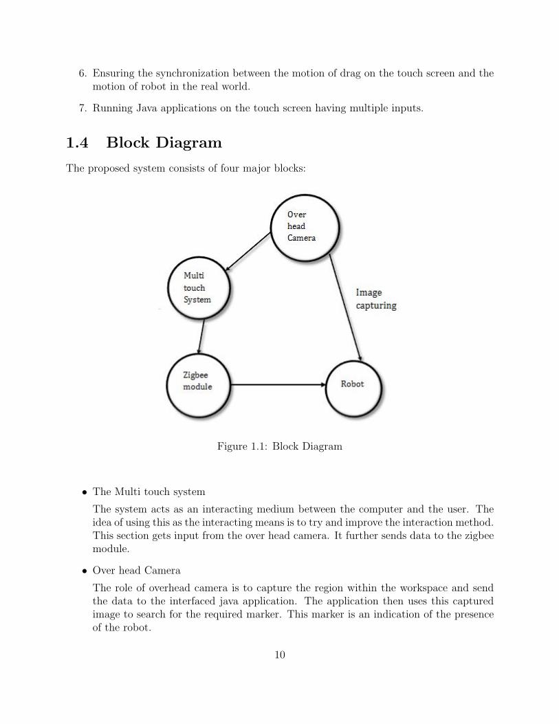
The proposed system consists of four major blocks:
Figure 1.1: Block Diagram
• The Multi touch system
The system acts as an interacting medium between the computer and the user. Theidea of using this as the interacting means is to try and improve the interaction method.This section gets input from the over head camera. It further sends data to the zigbeemodule.
• Over head Camera
The role of overhead camera is to capture the region within the workspace and sendthe data to the interfaced java application. The application then uses this capturedimage to search for the required marker. This marker is an indication of the presenceof the robot.
10

• Zigbee module
The zigbee module is the wireless module that communicates with robot. The com-munication involves transmission of the required parameters. The parameters involvethe amount of distance to be travel and the angle through which the robot needs tobe rotated.
• Robot
The robot is a four wheeled robot and which is controlled by an Atmega 328 chip. Therole of the microcontroller is to receive the data from the zigbee module and decodethe data in order to find the distance and angle to be covered.
11

Chapter 2
Literature Survey
1. Software driven Multi Touch input display as an improved, intuitive, and practicalinteraction device, Bradley Hayes, 2008 Boston college[9]
This thesis examines and investigates the substitution of the mouse for a more naturalmeans of human computer interaction, ranging from manipulating WIMP-based appli-cations to developing post-WIMP interfaces and exploring their usefulness. The WIMP(Window, Icon, Menu, and Pointer) interface has been the standard paradigm for thepersonal computing era. Their use is optimized for the keyboard and mouse input de-vice pair, tools that have remained fundamentally stagnant with regard to innovationfor decades. Accomplished through the construction of a touchscreen with variablelevels of contact detection, targeted demo applications not only show the effectivenessof such an input apparatus but introduce the potential for previously unexplored levelsof interaction.
2. A FTIR based Multit Touch Table Using Pulsed Illumination for noise Suppression,Uwe Hahne, Marc Alexa, Bjorn Bollensdorff, Ingo Bressler, Stefan Elstner,2008, TUBerlin[1]
Touch Sensing based on Frustrated Total Internal Reflection (FTIR) is capable ofsensing multiple touch points on a projection screen. Infrared light is totally reflectedwithin a screen, and on touch diffusely reflected from the finger tip. This diffusereflection is captured with a camera and fingertips are localized by blob detectingimage processing. This approach suffers from surrounding infrared light and a smallamount of light leaving the screen and illuminating the user so far it can only be used incontrolled lighting conditions. In our new approach, we obtain a dynamic backgroundsubtraction, which makes detection of fingertips possible even in the presence of non-constant, bright illumination conditions.
3. Multi Touch Interaction Wall, Jefferson Y. Han, 2006 Courant Institute of Mathemat-ical Sciences,New York University[7]
Touch is a very natural and intuitive way for people to interact. However, typicaltouchscreen technology, such as that commonly found in kiosks and interactive white-
12
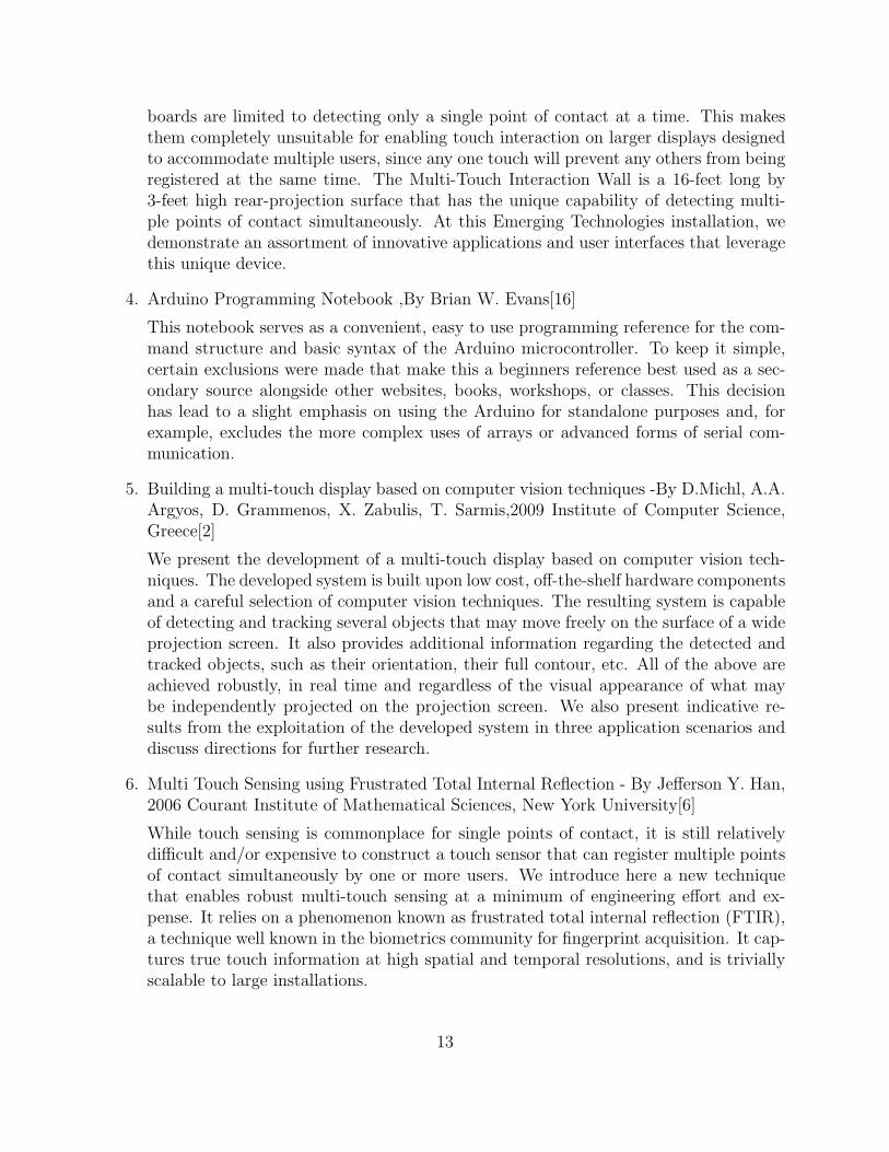
boards are limited to detecting only a single point of contact at a time. This makesthem completely unsuitable for enabling touch interaction on larger displays designedto accommodate multiple users, since any one touch will prevent any others from beingregistered at the same time. The Multi-Touch Interaction Wall is a 16-feet long by3-feet high rear-projection surface that has the unique capability of detecting multi-ple points of contact simultaneously. At this Emerging Technologies installation, wedemonstrate an assortment of innovative applications and user interfaces that leveragethis unique device.
4. Arduino Programming Notebook ,By Brian W. Evans[16]
This notebook serves as a convenient, easy to use programming reference for the com-mand structure and basic syntax of the Arduino microcontroller. To keep it simple,certain exclusions were made that make this a beginners reference best used as a sec-ondary source alongside other websites, books, workshops, or classes. This decisionhas lead to a slight emphasis on using the Arduino for standalone purposes and, forexample, excludes the more complex uses of arrays or advanced forms of serial com-munication.
5. Building a multi-touch display based on computer vision techniques -By D.Michl, A.A.Argyos, D. Grammenos, X. Zabulis, T. Sarmis,2009 Institute of Computer Science,Greece[2]
We present the development of a multi-touch display based on computer vision tech-niques. The developed system is built upon low cost, off-the-shelf hardware componentsand a careful selection of computer vision techniques. The resulting system is capableof detecting and tracking several objects that may move freely on the surface of a wideprojection screen. It also provides additional information regarding the detected andtracked objects, such as their orientation, their full contour, etc. All of the above areachieved robustly, in real time and regardless of the visual appearance of what maybe independently projected on the projection screen. We also present indicative re-sults from the exploitation of the developed system in three application scenarios anddiscuss directions for further research.
6. Multi Touch Sensing using Frustrated Total Internal Reflection - By Jefferson Y. Han,2006 Courant Institute of Mathematical Sciences, New York University[6]
While touch sensing is commonplace for single points of contact, it is still relativelydifficult and/or expensive to construct a touch sensor that can register multiple pointsof contact simultaneously by one or more users. We introduce here a new techniquethat enables robust multi-touch sensing at a minimum of engineering effort and ex-pense. It relies on a phenomenon known as frustrated total internal reflection (FTIR),a technique well known in the biometrics community for fingerprint acquisition. It cap-tures true touch information at high spatial and temporal resolutions, and is triviallyscalable to large installations.
13

7. A Low Cost Infrastructure for Table Top Games -By Christopher Wolfe, J. DavidSmith and T.C. Nicholas Graham School of Computing, Canada[3]
Tabletop games provide an intimate gaming experience where groups of friends caninteract in a shared space using shared physical props. Digital tabletop games showgreat promise in bringing this experience to video game players. However the cost ofdeveloping tabletop games is high due to the need for expensive hardware and complexsoftware. In this paper, we introduce EquisFTIR, a low-cost hardware and softwareinfrastructure for digital tabletop gaming.
8. Synthesis and Control on Large Scale Multi-Touch Sensing Displays -By Philip L.Davidson, Jefferson Y. Han, New York University[4]
In this paper, we describe our experience in musical interface design for a large scale,high-resolution, multi-touch display surface. We provide an overview of historical andpresent day context in multi-touch audio interaction, and describe our approach toanalysis of tracked multi-finger, multi-hand data for controlling live audio synthesis.The musicians need to manipulate many simultaneous degrees of freedom in audiosynthesis has long driven the development of novel interface devices. Touch sensorsintegrated with graphical display functionality can provide intuitively direct interac-tivity with richly dynamic context; however they are typically only able to respond toa single point of contact a time, making them quite limiting for musical input. Multi-touch sensors on the other hand permit the user fully bi-manual operation as well aschording gestures, offering the potential for great input expression. Such devices alsoinherently accommodate multiple users, which makes them especially useful for largerinteraction scenarios such as interactive tables.
9. Zigbee: Wireless Control that Simply Works -By William C. Crai, Program ManagerWireless Communications, ZMD America[13]
There are many wireless monitoring and control applications for industrial and homemarkets which require longer battery life, lower data rates and less complexity thanavailable from existing wireless standards. These standards provide higher data ratesat the expense of power consumption, application complexity and cost. What thesemarkets need, in many cases, is a standards-based wireless technology having the per-formance characteristics that closely meet the requirements for reliability, security, lowpower and low cost. This standards-based, interoperable wireless technology will ad-dress the unique needs of low data rate wireless control and sensor-based networks.For such wireless applications, a standard has been developed by the IEEE: ”TheIEEE 802.15 Task Group 4 is chartered to investigate a low data rate solution withmulti-month to multi-year battery life and very low complexity. It is intended to oper-ate in an unlicensed, international frequency band”. Potential applications are homeautomation, wireless sensors, interactive toys, smart badges and remote controls.
14
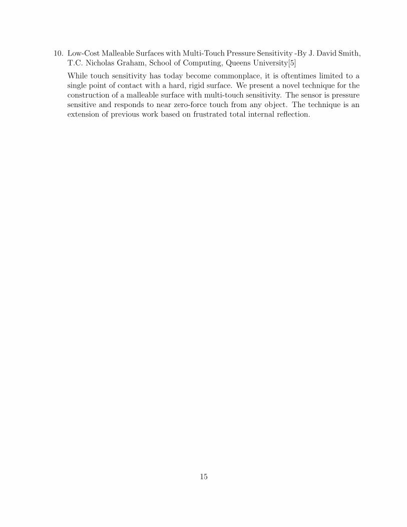
10. Low-Cost Malleable Surfaces with Multi-Touch Pressure Sensitivity -By J. David Smith,T.C. Nicholas Graham, School of Computing, Queens University[5]
While touch sensitivity has today become commonplace, it is oftentimes limited to asingle point of contact with a hard, rigid surface. We present a novel technique for theconstruction of a malleable surface with multi-touch sensitivity. The sensor is pressuresensitive and responds to near zero-force touch from any object. The technique is anextension of previous work based on frustrated total internal reflection.
15

Chapter 3
FTIR Concepts
There are various methods by which multi touch system can be made. Some of these arelisted below:
1. Frustrated Total Internal Reflection(FTIR)
2. Diffused Illumination (DI)
3. Using Capacitive or Resistive screen
4. And various others
The concept of FTIR is in existing for a long time but a successful implementation of thisconcept was demonstrated by Jeff Han[6] at the TED in the year 2005. The FTIR conceptuses a combination of optics and image processing in order to find out the touch points. Ascan be seen in the figure 1, the IR led are placed facing the edge of the acrylic sheet. Thisensures that the IR light rays experience Total Internal Reflection at the boundary of theacrylic sheet and air.
Figure 3.1: FTIR concept
16
As the IR light rays are experiencing total internal reflection the IR camera cannot detectthese single light rays.
But when the user places his/her finger on the screen the total internal reflection isdisturbed at that particular point. And thus at this point a lot IR light get concentrated.This along with the fact that the camera and light rays are almost parallel to each othermakes the detection of the IR blob easier. These blobs are the area where the user makescontact with the surface of the acrylic sheet. The blobs are detected using IR camera placedbelow the acrylic sheet.
3.1 FTIR Layers
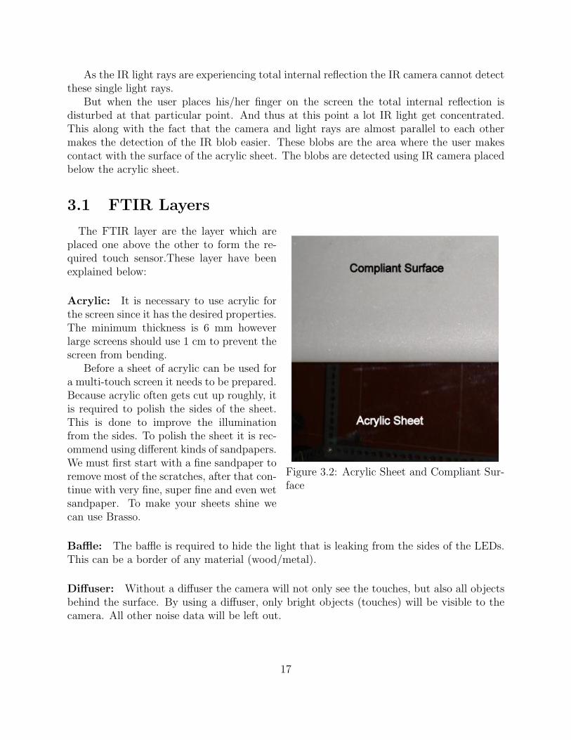
Figure 3.2: Acrylic Sheet and Compliant Sur-face
The FTIR layer are the layer which areplaced one above the other to form the re-quired touch sensor.These layer have beenexplained below:
Acrylic: It is necessary to use acrylic forthe screen since it has the desired properties.The minimum thickness is 6 mm howeverlarge screens should use 1 cm to prevent thescreen from bending.
Before a sheet of acrylic can be used fora multi-touch screen it needs to be prepared.Because acrylic often gets cut up roughly, itis required to polish the sides of the sheet.This is done to improve the illuminationfrom the sides. To polish the sheet it is rec-ommend using different kinds of sandpapers.We must first start with a fine sandpaper toremove most of the scratches, after that con-tinue with very fine, super fine and even wetsandpaper. To make your sheets shine wecan use Brasso.
Baffle: The baffle is required to hide the light that is leaking from the sides of the LEDs.This can be a border of any material (wood/metal).
Diffuser: Without a diffuser the camera will not only see the touches, but also all objectsbehind the surface. By using a diffuser, only bright objects (touches) will be visible to thecamera. All other noise data will be left out.
17

Compliant layer: With a basic FTIR setup, the performance mainly depends on howgreasy the fingertips of the user are. Wet fingers are able to make better contact with thesurface. Dry fingers and objects wont be able to frustrate the TIR. To overcome this problemit is recommended to add a compliant layer on top of the surface. Instead of frustrating thetotal internal reflection by touch, a compliant layer will act as a proxy. The complaint layercan be made out of a silicon material[15] such as ELASTOSIL M 4641. To protect andimprove the touch surface, rear projection material such as Rosco Gray can be used. Withthis setup it is no longer required to have a diffuser on the rear side.
3.2 Strength and Weaknesses
There are various method of making the touch sensor. These various methods have theirrespective advantages and disadvantages. The strength and weaknesses of Frustrated TotalInternal Reflection method of making a touch sensor are as follows:
The strength includes:
1. High contrasting blob. Blobs are the touch points where the user of the system ismaking contact with the acrylic sheet. High contrasting blobs enables high touchsensitivity and avoids applying large amount of pressure.
2. Varying amount of pressure can be sensed and thus a new dimension can be added tothe touch points.
3. With a compliant surface, it can be used with something as small as a pen tip
The weakness includes:
1. The inability of the system to recognize objects or markers which are also known asfiducials.
2. Requires a compliant surface (silicone rubber) for proper use - no glass surface
Even with these weaknesses FTIR method is simpler method to implement as comparedto the other methods like the Diffused Illumination[14]. The FTIR method cannot recognizeobjects or fiducials, but if the sensitivity of the screen in improved using powerful IR ledit is possible to recognize objects as well. The object that would be detected can resultin ambiguous detection. Thus to avoid ambiguous detection using FTIR method, variousobjects need to listed along with the pattern of blobs that appear. For example, if a cellphoneis placed on the acrylic sheet there is a possibility of obtain a rectangular blob. Or if a coinis placed there is a possibility of getting a circular blob.
In order to avoid this ambiguous decision making DI method should be used. The use ofmarker which has known definition for a particular object in that particular system makesthe detection of object easier.
18

Chapter 4
Hardware Description
4.1 Introduction
There are two sections in the project. One is the software and the other is the hardwaresection. The hardware section involves the making of the robot and the construction of thetouch table. This section of the report focuses on is the electronic hardware involved in themulti touch system and the hardware used to make the robot.
The hardware section is further segregated in the following sub-sections:
1. Multi touch table
2. XBee communication
3. Robot Movement
The hardware apparatus exists to transform the task of collecting and interpreting screencontact data into a binary blob tracking problem. The actual display presentation is accom-plished via rear projection, using a translucent material affixed to the screen. By utilizingrows of infrared LEDs attached to the periphery of the screen directed inwards toward thecenter of the glass, any object in direct contact will reflect the infrared light. This light isthen processed by the webcam behind the screen, isolated by an infrared-pass filter.
The hardware construction of the project can be mainly divided into 3 parts: constructionof the Touch Screen, construction of the Atmega boards atop the robots and communicationbetween the robot and the touch table.
19

4.2 Touch Table
4.2.1 Touch Screen
A projecting surface is needed as a screen to display the interface and to provide appro-priate transmission characteristics for the IR LED to pass through and to reflect to the IRcamera. The acrylic glass has the following characteristics making it the ideal one to use ina multi-touch interface system:
• Easy handling and processing
• High boiling and melting point.
• Has a density of 1,1501,190 kg/m3,hence it is light weight.
• Allows infrared light of up to 2800 nm wavelength to pass. IR of longer wavelengths,up to 25,000 nm, is essentially blocked.
• Transmits up to 92% of visible light (3 mm thickness), and gives a reflection of about4% from each of its surfaces on account of its refractive index of 1.4893 to 1.4899.
A diffuser is placed behind the screen so that only bright surfaces are visible to the camera.With a basic FTIR setup, the performance mainly depends on how greasy the fingertips ofthe user are. Wet fingers are able to make better contact with the surface. Dry fingers andobjects wont be able to frustrate the TIR. To overcome this problem it is recommended toadd a compliant layer on top of the surface. Instead of frustrating the total internal reflectionby touch, a compliant layer will act as a proxy. The complaint layer can be made out of asilicon material such as ELASTOSIL M 4641. To protect and improve the touch surface,rear projection material such as Rosco Gray can be used.
Figure 4.1: Touch table
The compliant surface or compliantlayer is simply an additional layer betweenthe projection surface and the acrylic. It en-hances the finger contact and gives you morerobust blobs, particularly when dragging asyour finger will have less adhesion to the sur-face. In the FTIR technique, the infraredlight is emitted into side the acrylic waveg-uide, the light travels inside the medium(due to total internal refection much like afiber optic cable), when you touch the sur-face of the acrylic (you frustrate this TIR ef-fect) causing the light to refract within themedium on points of contact and creatingthe blobs (bright luminescent objects).
20

4.2.2 IR Led Array
Figure 4.2: IR Array in working condition.The red points indicate that IR LED is work-ing. They are not invisible to naked eyes.
We prefer IR LEDs over normal LEDs asthere is a difference in their electrical prop-erties. Infrared LEDs have a lower forwardvoltage, and a higher rated current com-pared to visible LEDs. This is due to differ-ences in the material properties of the junc-tion. A typical drive current for an infraredLED can be as high as 50 milliamps. This isessential for the FTIR as the intensity on ev-ery point on the surface must be constant. Ifthere are distortions on the surface the cam-era may detect it as a touch and this maylead to an error.
Common infrared LED that emits in-frared rays has the same appearance withvisible light LED. Its appropriate operatingvoltage is around 1.4v and the current is gen-erally smaller than 20mA. Current limitingresistances are usually connected in series in the infrared LED circuits to adjust the voltages,helping the LEDs to be adapted to different operating voltages.
Table 4.1: IR led Specifications
Parameter Symbol Rating UnitsForward Current IF 50 mA
Pulse Forward Current IFP 1 AReverse Voltage VR 5 V
Power Dissipation PD 95 mWOperating Temperature TOPR -20→ +70 CHalf Power Beam Angle δ 10 degree
Peak Emission Wavelength λP 850 nmSpectral Bandwidth δλ 30 nm
Infrared LED chips with different wavelengths can be applied in extensive devices, forexample, Infrared LED chip with wavelength of
1. 940nm: suitable to be used in remote controller, such as remote controllers for house-hold appliances.
21
2. 808nm: suitable to be used in medical treatment appliances, space optical communi-cation, infrared illumination and the pumping sources of the solid-state lasers.
3. 830nm: suitable to be used in the automated card reader system in freeway.
4. 840nm: suitable to be used in colored zoom infrared waterproof video camera.
5. 850nm: suitable to be used in video cameras that are applied in digital photography,monitoring system, door phone, FTIR and so on.
6. 870nm: suitable to be used in video cameras in marketplace and crossroad.
For our project, we have used IR0510. Its datasheet and description is as follows:Infrared Emitting Diode: IR0510General Description: IR0510 is a high output power and high speed GaAlAs infrared
light emitting diode mounted in a clear epoxy looking package. It emits narrow band ofradiation peaking at 850nm. The general specifications of the LED IR0510 are:
4.2.3 IR Detection Camera
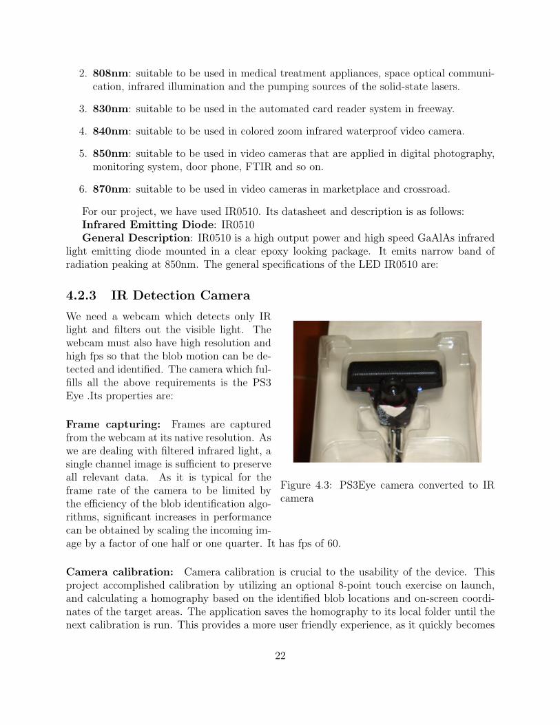
Figure 4.3: PS3Eye camera converted to IRcamera
We need a webcam which detects only IRlight and filters out the visible light. Thewebcam must also have high resolution andhigh fps so that the blob motion can be de-tected and identified. The camera which ful-fills all the above requirements is the PS3Eye .Its properties are:
Frame capturing: Frames are capturedfrom the webcam at its native resolution. Aswe are dealing with filtered infrared light, asingle channel image is sufficient to preserveall relevant data. As it is typical for theframe rate of the camera to be limited bythe efficiency of the blob identification algo-rithms, significant increases in performancecan be obtained by scaling the incoming im-age by a factor of one half or one quarter. It has fps of 60.
Camera calibration: Camera calibration is crucial to the usability of the device. Thisproject accomplished calibration by utilizing an optional 8-point touch exercise on launch,and calculating a homography based on the identified blob locations and on-screen coordi-nates of the target areas. The application saves the homography to its local folder until thenext calibration is run. This provides a more user friendly experience, as it quickly becomes
22
tedious to calibrate each time the application is launched. This step utilizes its own routinefor identifying blobs, as precision is of paramount importance.
4.3 Microcontroller-Atmega328
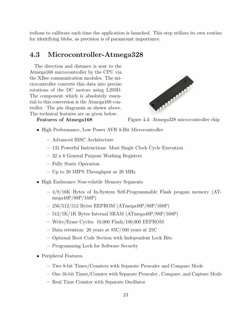
Figure 4.4: Atmega328 microcontroller chip
The direction and distance is sent to theAtmega168 microcontroller by the CPU viathe XBee communication modules. The mi-crocontroller converts this data into preciserotations of the DC motors using L293D.The component which is absolutely essen-tial to this conversion is the Atmega168 con-troller. The pin diagramis as shown above.The technical features are as given below:
Features of Atmega168
• High Performance, Low Power AVR 8-Bit Microcontroller
– Advanced RISC Architecture
– 131 Powerful Instructions Most Single Clock Cycle Execution
– 32 x 8 General Purpose Working Registers
– Fully Static Operation
– Up to 20 MIPS Throughput at 20 MHz
• High Endurance Non-volatile Memory Segments
– 4/8/16K Bytes of In-System Self-Programmable Flash progam memory (AT-mega48P/88P/168P)
– 256/512/512 Bytes EEPROM (ATmega48P/88P/168P)
– 512/1K/1K Bytes Internal SRAM (ATmega48P/88P/168P)
– Write/Erase Cycles: 10,000 Flash/100,000 EEPROM
– Data retention: 20 years at 85C/100 years at 25C
– Optional Boot Code Section with Independent Lock Bits
– Programming Lock for Software Security
• Peripheral Features
– Two 8-bit Timer/Counters with Separate Prescaler and Compare Mode
– One 16-bit Timer/Counter with Separate Prescaler , Compare, and Capture Mode
– Real Time Counter with Separate Oscillator
23
– Six PWM Channels
– 8-channel 10-bit ADC in TQFP and QFN/MLF package
– 6-channel 10-bit ADC in PDIP Package
– Programmable Serial USART
– Master/Slave SPI Serial Interface
– Byte-oriented 2-wire Serial Interface (Philips I2C compatible)
– On-chip Analog Comparator
– Interrupt and Wake-up on Pin Change
• Special Microcontroller Features
– Power-on Reset and Programmable Brown-out Detection
– Internal Calibrated Oscillator
– External and Internal Interrupt Sources
– Six Sleep Modes: Idle, ADC Noise Reduction, Power-save, Power-down, Standby,and Extended Standby
• I/O and Packages
– 23 Programmable I/O Lines
– 28-pin PDIP, 32-lead TQFP, 28-pad QFN/MLF and 32-pad QFN/MLF
• Operating Voltage:
– 1.8 - 5.5V for ATmega48P/88P/168PV
∗ 2.7 - 5.5V for ATmega48P/88P/168P
– Temperature Range:
– -40C to 85C
• Speed Grade:
– ATmega48P/88P/168PV: 0 - 4 MHz @ 1.8 - 5.5V, 0 - 10 MHz @ 2.7 - 5.5V
– ATmega48P/88P/168P: 0 - 10 MHz @ 2.7 - 5.5V, 0 - 20 MHz @ 4.5 - 5.5V
24

4.3.1 Programming Robot Board
The programming board that is used is called a Arduino. Arduino is an open-sourceelectronics prototyping platform based on flexible, easy-to-use hardware and software. It’sintended for artists, designers, hobbyists, and anyone interested in creating interactive ob-jects or environments.
Arduino can sense the environment by receiving input from a variety of sensors and canaffect its surroundings by controlling lights, motors, and other actuators. The microcontrolleron the board is programmed using the Arduino programming language (based on Wiring)and the Arduino development environment (based on Processing)[18]. Arduino projects canbe stand-alone or they can communicate with software on running on a computer (e.g. Flash,Processing, MaxMSP).
The boards can be built by hand or purchased preassembled; the software can be down-loaded for free. The hardware reference designs (CAD files) are available under an open-source license.
Figure 4.5: USB board used to program themicrocontroller
The robot specific board is designedby the group using the Eagle software. Theboard is single sided board.All the portsof the microcontroller has been pulled out.The Zigbee(Xbee modules) modules are in-terfaced to RXD and TXD pin of the mi-crocontroller. The supply to the board isa 12V supply. This supply is converted to5V using 7805 voltage regulater. 5V suplycan also be directly give to the board. Thesupply and and reset led indicate is micron-troller is properly powered or the microcontroller is properly reset. The board has provisonto interface four independent motors at time. The motor are interfaced to the PORTB andPORTC.
A motor driver daughter board was also designed which can be directly interface tothe programming board. Along with this a Xbee module based daughter board was alsodesigned, which is compatible to the Arduino programming board.
25

4.4 XBee Communication Modules
Figure 4.6: The Zigbee modules used for wire-less communication
The XBee modules are used to send dis-tance and angle from old position to thenew position to the robot. The transmit-ter is connected to the CPU whereas thereceiver is connected on the robot. TheXBee RF Modules were implement IEEE802.15.4 standards and support the uniqueneeds of low-cost, low-power wireless sen-sor networks. The modules require mini-mal power and provide reliable delivery ofdata between devices. The modules operatewithin the ISM 2.4 GHz frequency band and are pin-for-pin compatible with each other.The key features of XBee are:
Table 4.2: Specifications
SpecificationsIndoor Range Upto 100 ft
Outdoor RF line of sight range Upto 300 ftTransmit Power Output 1mW
RF Data Rate 250,000 bpsSerial Interface Data Rate 1200 bps-250 kbps
Receiver Sensitivity -92 dBmPower Requirement
Supply Voltage 2.8-3.4 VTransmit Current 45 mAReceive current 50 mA
Networking and SecuritySupported Network Topologies Point to point, point to multipoint, peer to peer
Number of Channels 16 Direct Sequence ChannelsAddressing Options PAN ID, Channels and Addresses
XBee RF Modules interface to a host device through a logic-level asynchronous serial port.Through its serial port, the module can communicate with any logic and voltage compatibleUART; or through a level translator to any serial device. Devices that have UART interfacecan directly to the pins of the RF module as shown in the figure:
Data enters the module UART through the DI pin as an asynchronous serial signal. Thesignal should idle high when no data is being transmitted. Each data byte consists of a startbit, 8 data bits and a stop bit. The following figure illustrates the serial bit pattern of datapassing through the module.
26

The module UART performs tasks, such as timing and parity checking, that are neededfor data communications. Serial communications depend on the two UARTs to be configuredwith compatible settings (baud rate, parity, start bits, stop bits, data bits). There are twomodes of operation are: Transparent Mode and API mode.
4.4.1 ZigBee v/s Bluetooth
ZigBee is broadly categorized as a low rate WPAN, and its closest technology is Bluetooth.They are two different technologies with very different areas of application and differentmeans of designing for those applications. While
• ZigBee is focused on control and automation, Bluetooth is focused on connectivitybetween laptops, PDAs, and the like, as well as more general cable replacement.
• ZigBee uses low data rate, low power consumption, and works with small packet de-vices; Bluetooth uses a higher data rate, higher power consumption, and works withlarge packet devices.
• ZigBee networks can support a larger number of devices and a longer range betweendevices than Bluetooth.
• ZigBee is designed to respond quickly, while Bluetooth takes much longer and couldbe detrimental to the application.
• Bluetooth must rely on fairly frequent battery recharging, while the whole goal ofZigBee is for a user to be able to put a couple of batteries in the devices and forgetabout them for long time.
Because of these differences, the technologies are not only geared toward different applica-tions, they don’t have the capability to extend out to other applications. Thus, a user couldeasily use both technologies as a wireless solution in a PAN to suit all types of applicationswithin that network. The technical details and differences between the two are listed below:
• Modulation technique:Bluetooth: Frequency Hopping Spread Spectrum (FHSS)ZigBee: Direct Sequence Spread Spectrum (DSSS)
• Protocol stack size:Bluetooth: 250 kbyteZigBee: 28 kbyte
• Battery:Bluetooth: Intended for frequent rechargingZigBee: Not rechargeable (one reason batteries will last for up to 10 years)
27

• Maximum network speed:Bluetooth: 1 Mbit/sZigBee:250 kbit/s
• Network range:Bluetooth: 1 or 100m, depending on radio classZigBee: Up to 70m
• Typical network join time:Bluetooth: 3 secondsZigBee: 30 milliseconds
28

Chapter 5
Software Description
The main tasks in the entire process are to detect robots lying on ground and the blobsof our fingertips. This requirement can be fulfilled by :
1. Object detection algorithm and
2. Blob detection algorithm
Object Detection Algorithm In edge detection we get only edge of the object. Solimitation of edge detection is that object of same edge might also get detected as robot.So to avoid it we go for template matching method. In this technique we go by followingalgorithm:
1. Capture images of objects to be detected.
2. Make its entry into the database
3. Now capture current image.
4. Perform edge detection
5. Check length and breadth of the successive edges
6. Compare length and breadth with database image parameters
7. Then find correlation coefficient of array elements of current and database image.
8. If correlation coefficient a threshold indicate the presence of the object using a cir-cle(say)
9. Display circle corresponding to our robot on the multi-touch screen.
29

Figure 5.1: Blob detection
Blob detection algorithm
For constructing and designing a inter-active tables mirrors commonly have to beused to allow a camera and projector con-figuration which results in a usable tableheight. Instead of showing detection of IRLight in GUI of our program we convert im-age obtained from our CAM into binary im-age. This binary image after inverting wedisplayed it on PC. Tracking touches on asurface involves setting up a pipeline of im-age processing operators that transform acamera image into user interface events.
Images captured by a camera are firstpre-processed to remove any unchanging parts using history subtraction. A connected com-ponents algorithm finds bright regions in the pre-processed image. These are the areas wheresomething is touching the surface. Post processing involves finding corresponding touches indifferent camera frames (temporal correlation) and transforming the camera coordinates toscreen coordinates.
When given the processed image, the blob detection module performs a sequential pixelcomparison to find edges of potential intentional contact points. Upon detection of a nonzerovalue, the algorithm begins a radial expansion about the coordinate. Each subsequentnonzero value has its coordinates added to a list as the expansion progresses, stopping onlyif a zero or value with a delta of greater than a constant,
δ = | current coordinate value−previous coordinate value|
As coordinates are evaluated, they are zeroed out to prevent overlapping points and infiniterecursion. Upon return from the expansion function, the centroid is calculated along with themean intensity. Blobs found with radii outside the specified acceptable range are discarded.
Once a list of all candidate points are computed and filtered, they are further pareddown through a process of small neighborhood elimination. If two centroids are found to bewithin a predetermined constant distance that with a weaker mean intensity is discarded.This neighborhood is optimally set to be a small region. The value used for this constant isprimarily affected by the delta used in the expansion function.
For touch programming, it is required that we identify different touch input. Along withidentifying different touch position it is required that the programming environment alsoupdates the position of the corresponding touch inputs. These requirements are required forall the multi touch system that uses TUIO protocol to communicate the touch data.
30

5.1 Community Core Vision(CCV)
Community Core Vision or CCV for short (also known as tbeta), is a open source/cross-platform solution for computer vision and machine sensing. It takes a video input streamand outputs tracking data (e.g. coordinates and blob size) and events (e.g. finger down,moved and released) that are used in building nui aware applications. CCV can interfacewith various web cameras and video devices as well as connect to various TUIO/OSC/XMLenabled applications and supports many multi-touch lighting techniques including: FTIR,DI, DSI, and LLP with expansion planned for the future vision applications (custom mod-ules/filters).CCV is released under the LGPL License. The main characteristics of CCV 1.2are:
• Cameras:
– Full PS3 camera support on windows
– Support for Firefly cameras on windows
• Fixes:
– Background Removal on startup
– GPU speed slightly faster than before
– New calibration technique - Can now calibrate even when there are false blobs
• Features:
– Simple GUI - The new interface is more intuitive and easier to understand anduse.
– Filters (dynamic background subtraction, high-pass, amplify/scaler, threshold) -This means it will work with all optical setups (FTIR, DI, LLP, DSI). More filterscan be added as modules.
– Camera Switcher - Have more than one camera on your computer? Now you canpress a button and switch to the next camera on your computer without havingto exit the application.
– Input Switcher- Want to use test videos instead of a live camera? Go ahead, pressa button and it will switch to video input.
– Dynamic Mesh Calibration - For people with small or large tables, now you canadd calibration points (for large displays) or create less points (smaller displays)while maintaining the same speed and performance.
– Image Reflection- Now you can flip the camera vertical or horizontal if it is thewrong way.
– Network Broadcasting - You can send OSC TUIO messages directly from theconfigapp for quick testing.
31

– Camera and application FPS details viewer - Now you can see the frame rate ofboth the tracker and camera that you are getting.
– GPU Mode - Utilize your GPU engine for accelerated tracking.
– Cross-platform - This works on windows, Mac, and Linux.
– Min/max blob tracking size sliders - Sets the minimum and maximum size blobsto look for
– Dynamic background subtraction ’learn speed’ slider - Sets the rate dynamicbackground subtraction occurs
– Movement threshold to eliminate jittery blobs - Sets the minimum amount a blobmust move to consider it as ’moving’. This helps with jitter
– Option to track dark or light blobs only (no more absolute background subtractionsince it causes inconsistencies)
– Startup in mini mode
– Logging system - In bin/logs you can find a text log file of what happened whenrunning the application. This should be useful in debugging errors
• Low Level features:
– Add-on support for openframeworks - Option to not use TUIO and use directlywith c++
– Classes rewritten to comply with openframeworks addon standards Communica-tion
– TUIO direct to Flash sending through TCP - Can now send TUIO to flash withoutFLOSC (currently doesn’t work on Windows Vista for unknown reason)
– Option to turn on/off width/height TUIO sending to comply with the TUIO 1.0protocol
– Now sending correct fseq, dX, dY, and maccel TUIO values.
5.2 Processing
Processing is an open project[19] initiated by Ben Fry and Casey Reas. It evolved fromideas explored in the Aesthetics and Computation Group at the MIT Media Lab. It isan open source programming language and environment for people who want to programimages, animation, and interactions. It is used by students, artists, designers, researchers,and hobbyists for learning, prototyping, and production. It is created to teach fundamentalsof computer programming within a visual context and to serve as a software sketchbook andprofessional production tool. Processing is free to download and available for GNU/Linux,Mac OS X, and Windows. Processing is a simple programming environment that was createdto make it easier to develop visually oriented applications with an emphasis on animation
32
and providing users with instant feedback through interaction. The developers wanted ameans to sketch ideas in code. As its capabilities have expanded over the past six years,Processing has come to be used for more advanced production-level work in addition toits sketching role. Originally built as a domain-specific extension to Java targeted towardsartists and designers, Processing has evolved into a full-blown design and prototyping toolused for large-scale installation work, motion graphics, and complex data visualization. Thelatest version of Processing can be downloaded at http://processing.org/download.
Processing consists of:
• The Processing Development Environment (PDE). This is the software that runs whenyou double-click the Processing icon. The PDE is an Integrated Development Envi-ronment (IDE) with a minimalist set of features designed as a simple introduction toprogramming or for testing one-off ideas.
• A collection of functions (also referred to as commands or methods) that make up thecore programming interface, or API, as well as several libraries that support more ad-vanced features such as drawing with OpenGL, reading XML files, and saving compleximagery in PDF format.
• A language syntax, identical to Java but with a few modifications.
• An active online community, hosted at http://processing.org. For this reason, refer-ences to Processing can be somewhat ambiguous. Are we talking about the API, thedevelopment environment, or the web site? We’ll be careful in this text when referringto each.
5.3 TUIO Protocol
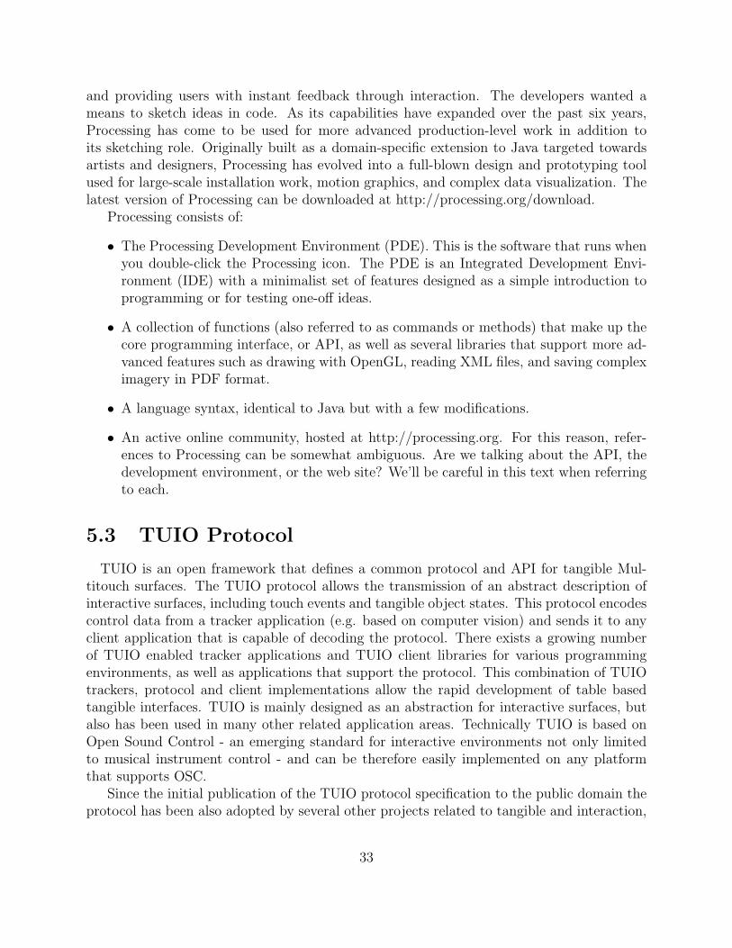
TUIO is an open framework that defines a common protocol and API for tangible Mul-titouch surfaces. The TUIO protocol allows the transmission of an abstract description ofinteractive surfaces, including touch events and tangible object states. This protocol encodescontrol data from a tracker application (e.g. based on computer vision) and sends it to anyclient application that is capable of decoding the protocol. There exists a growing numberof TUIO enabled tracker applications and TUIO client libraries for various programmingenvironments, as well as applications that support the protocol. This combination of TUIOtrackers, protocol and client implementations allow the rapid development of table basedtangible interfaces. TUIO is mainly designed as an abstraction for interactive surfaces, butalso has been used in many other related application areas. Technically TUIO is based onOpen Sound Control - an emerging standard for interactive environments not only limitedto musical instrument control - and can be therefore easily implemented on any platformthat supports OSC.
Since the initial publication of the TUIO protocol specification to the public domain theprotocol has been also adopted by several other projects related to tangible and interaction,
33
such as the NUI group and several other tangible interaction platforms. The TUIO protocolhas been widely adopted and used for multi touch interaction.
Figure 5.2: TUIO Protocol
TUIO protocol definition is used to pro-vide a general and versatile communica-tion interface between tangible tabletop con-troller interfaces and underlying applicationlayers. It was designed to meet the needsof tabletop interactive multi-touch surfaces,where the user is able to manipulate a setof objects and draw gestures onto the tablesurface with the finger tips. The objects aretracked by a sensor system and can be iden-tified and located in position and orientationon the table surface.
The programming language is requiredto understand the TUIO protocol. Thisis because the touch data from the TUIOtracker application is communicated to the client application. The client application is re-quired to understand this TUIO protocol. The data that is sent involves information likethe touch position, touch ID, session ID. The touch tracker also notifies the programmingenvironment when a new touch input is detected, a existing touch input is removed or anexisting touch input is updated.
Open Sound Control
The TUIO protocol is encoded using the Open Sound Control format, which provides anefficient binary encoding method for the transmission of arbitrary controller data. Thereforethe TUIO messages can be basically transmitted through any channel that is supported byan actual OSC implementation. The default transport method for the TUIO protocol is theencapsulation of the binary OSC bundle data within UDP packets sent to the default TUIOport number 3333. This default transport method is usually referred as TUIO/UDP, andmost implementations are based on this method due to its simplicity and speed when sentover a local or wide area network. Since OSC is not directly bound to a dedicated transportmethod, alternative transport channels such as TCP can be employed to transmit the OSCencoded TUIO data. As introduced with the TUIO 1.1 implementations, there are alreadyseveral alternative transport methods available, such as TUIO/TCP and TUIO/FLC (flashlocal connection via shared memory) to interface with Adobe Flash applications for example.
Efficiency and mode of Commnication In order to provide low latency communica-tion our implementation of the TUIO protocol uses UDP transport. When using UDP thepossibility exists that some packets will be lost. Therefore, our implementation of the TUIOprotocol includes redundant information to correct possible lost packets, while maintaining
34

an efficient usage of the channel. An alternative TCP connection would assure the securetransport but at the cost of higher latency. For efficiency reasons set messages are packedinto a bundle to completely use the space provided by a UDP packet. Each bundle also in-cludes a redundant alive message to allow for the possibility of packet loss. For larger objectsets, a bundle with a series of set messages, each including an alive message, are transmitted.When the surface is quiescent, alive messages are sent at a fixed rate dependent on the chan-nel quality, for example once every second, to ensure that the receiver eventually acquires aconsistent view of the set of alive objects. The state of each alive but unchanged object isperiodically resent with additional set messages. This redundant information is resent at alower rate, and includes only a subset of the unchanged objects at each update. The subsetis continuously cycled so that each object is periodically addressed.
Attributes The Session ID is a unique identifier for each individual TUIO object, cursoror blob, which is maintained during its individual presence during a session. This uniqueID allows to distinguish various markers with the same symbol ID or to identify individualunmarked blobs or cursors. The session ID usually is unique for all profiles, although usingthe same session ID within the cursor and blob profile for example indicates a reference tothe same individual instance. This allows the additional transmission of the cursor or objectgeometry using the blob profile if desired.
The attributes defined in this section reflect the object properties we considered importantfor an interactive surface interface. Some of these attributes (ID, position and angle) areretrieved directly by the sensor. Others (speed, acceleration) are derived from these primaryattributes using timing information. Computing these attributes on the low level side of atangible user interface system is more reliable, since the necessary timing information doesnot need to be available to clients.
5.4 Ardunio IDE
The Arduino IDE[18] is a cross-platform application written in Java which is derived fromthe IDE made for the Processing programming language and the Wiring project. It is de-signed to introduce programming to artists and other newcomers unfamiliar with softwaredevelopment. It includes a code editor with features such as syntax highlighting, bracematching, and automatic indentation, and is also capable of compiling and uploading pro-grams to the board with a single click. There is typically no need to edit Makefiles or runprograms on the command line. The Arduino IDE comes with a C/C++ library called”Wiring” (from the project of the same name), which makes many common input/outputoperations much easier. Arduino programs are written in C/C++, although users only needto define two functions in order to make a runnable program: setup() a function run onceat the start of a program which can be used for initializing settings, and loop() a functioncalled repeatedly until the board is powered off. A typical first program for a microcontrolleris to simply blink a LED (light-emitting diode) on and off. In the Arduino environment, theuser might write a program like this:
35

#define LED_PIN 13
void setup ()
pinMode (LED_PIN, OUTPUT); // enable pin 13 for digital output
void loop ()
digitalWrite (LED_PIN, HIGH); // turn on the LED
delay (1000); // wait one second (1000 milliseconds)
digitalWrite (LED_PIN, LOW); // turn off the LED
delay (1000); // wait one second
The above code would not be seen by a standard C++ compiler as a valid program, so whenthe user clicks the ”Upload to I/O board” button in the IDE, a copy of the code is written toa temporary file with an extra include header at the top and a very simple main() functionat the bottom, to make it a valid C++ program. The Arduino IDE uses the GNU toolchainand AVR Libc to compile programs, and uses avrdude to upload programs to the board.
36

Chapter 6
Hardware Implementation
There are two section of hardware implementation:
1. Touch table related hardware
2. Robot Hardware related hardware
This chapter on hardware implementation includes how the touch table is constructed, howthe led circuit is designed, the modification of the visible light camera and designing ofmicrocontroller compatiable motor controller daughter board.
6.1 Touch Table
The material required for the construction of the touch table and the material used aretabulated below:
Table 6.1: Hardware Components
Sr. no. Component Material used1. Screen Acrylic Glass2. Projector Epson EB-X63. Projection Surface Gateway Paper/ Tracing Paper4. IR Camera Modified PS3eye5. Frame Metal railings6. IR leds IR 05107. Adherents Screws, Nuts, Bolts
6.1.1 Construction of Touch Sensor
The touch sensor is the surface on which the user interacts with the system. The touchsensor is an acrylic sheet of 10mm thickness. The thick is so chose to ensure that all the
37
IR light emitted by the IR led enter into the acrylic sheet and experiances total internalreflection within it. The acrylic was first cleaned wih soap water in order to avoid the effectof any fingerprint or dust present on the surface of the acrylic sheet.
This acrylic sheet is surrounded by an array of IR leds. The leds are sepearted by adistance of 1 inch. The sensor was first test with an array of five leds of different types.After analysing the result of these leds, IR 0510 was selected.
6.1.2 Construction of I.R Circuitry
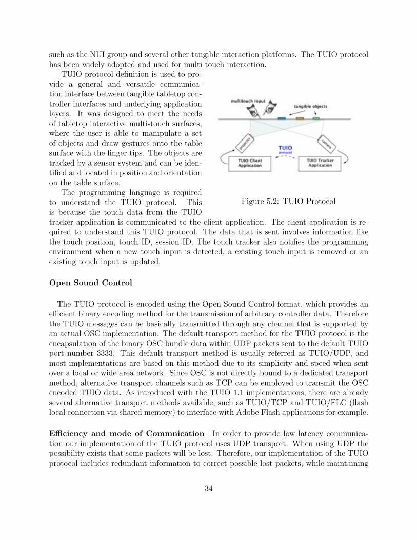
Figure 6.1: IR circuitry for 8 IR leds
The above circuit was designed for eight IR led with the following specification:Power supply voltage=15VPower supply voltage=1.5VLED current rating=50mANumber of LEDs: 8Each side of the acrylic glass has an accompanied IR LED circuitry so that the illuminationthroughout the screen is uniform. There are thus 4 strips of I.R LED, one for each side. Eachstrip has as many LEDs as the length of the strip, one for each inch of the strip. To keepthe required current to a minimum, the LEDs on each side were separated into three groupsof five. Now we had to give current and voltage to all LEDs using only one 15V supply.We calculated the current and voltage which each LED will get for different serial parallelcombinations and then we chose the best one which required resistance of about 24ohms.
These groups were wired in series, connected in parallel to the power source. One circuitis then completely soldered and the adjustments are evaluated so that the LEDs fit into theenclosure. We then repeat this process for all the remaining sides then. In order to provide aconvenient source of power and ground, cable is run up each side of the insides of the frameswith the plastic coating stripped at key locations.
Once the LED circuits are wired and fixed in place, the circuit is powered and examinedusing a cell phone camera or other I.R sensitive image capture device. Once is verified thatall the LEDs are working, the solder joints are double checked for stability. The webcam isthen attached orthogonally oriented with respect to the acrylic directly beneath the centrepoint of the acrylic.
6.1.3 Modification of Visible Light Camera
We followed the following steps to convert a very good working camera into an Infra redCamera.
38
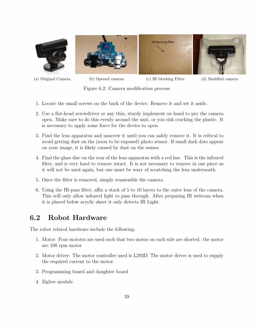
(a) Original Camera (b) Opened camera (c) IR blocking Filter (d) Modified camera
Figure 6.2: Camera modification process
1. Locate the small screws on the back of the device. Remove it and set it aside.
2. Use a flat-head screwdriver or any thin, sturdy implement on hand to pry the cameraopen. Make sure to do this evenly around the unit, or you risk cracking the plastic. Itis necessary to apply some force for the device to open.
3. Find the lens apparatus and unscrew it until you can safely remove it. It is critical toavoid getting dust on the (soon to be exposed) photo sensor. If small dark dots appearon your image, it is likely caused by dust on the sensor.
4. Find the glass disc on the rear of the lens apparatus with a red hue. This is the infraredfilter, and is very hard to remove intact. It is not necessary to remove in one piece asit will not be used again, but one must be wary of scratching the lens underneath.
5. Once the filter is removed, simply reassemble the camera.
6. Using the IR-pass filter, affix a stack of 5 to 10 layers to the outer lens of the camera.This will only allow infrared light to pass through. After preparing IR webcam whenit is placed below acrylic sheet it only detects IR Light.
6.2 Robot Hardware
The robot related hardware include the following:
1. Motor: Four mototrs are used such that two motor on each side are shorted. the motorare 100 rpm motor
2. Motor driver: The motor controller used is L293D. The motor driver is used to supplythe required current to the motor.
3. Programming board and daughter board
4. Zigbee module
39
6.2.1 Designed board
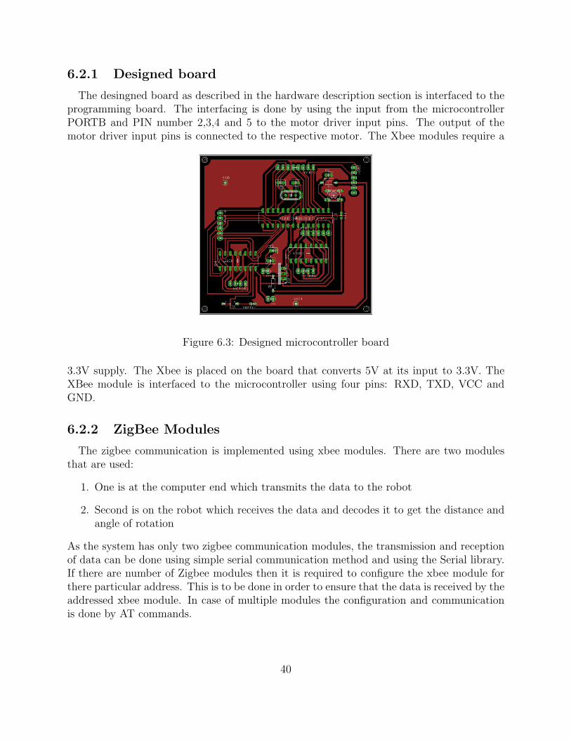
The desingned board as described in the hardware description section is interfaced to theprogramming board. The interfacing is done by using the input from the microcontrollerPORTB and PIN number 2,3,4 and 5 to the motor driver input pins. The output of themotor driver input pins is connected to the respective motor. The Xbee modules require a
Figure 6.3: Designed microcontroller board
3.3V supply. The Xbee is placed on the board that converts 5V at its input to 3.3V. TheXBee module is interfaced to the microcontroller using four pins: RXD, TXD, VCC andGND.
6.2.2 ZigBee Modules
The zigbee communication is implemented using xbee modules. There are two modulesthat are used:
1. One is at the computer end which transmits the data to the robot
2. Second is on the robot which receives the data and decodes it to get the distance andangle of rotation
As the system has only two zigbee communication modules, the transmission and receptionof data can be done using simple serial communication method and using the Serial library.If there are number of Zigbee modules then it is required to configure the xbee module forthere particular address. This is to be done in order to ensure that the data is received by theaddressed xbee module. In case of multiple modules the configuration and communicationis done by AT commands.
40
Chapter 7
Software Implementation
7.1 Libraries
The programming of the system is done in Java based processing environment and usinglibraries that use the pure java language. The libraries include the use of the following:
1. TUIOThis library is required so as to decode the touch points and the data related to it.The library is capable of decoding the data from many blob tracking environment. Thelibrary can identify touch points and fiducial objects. Whenever a touch point(Touchcursor) is added, removed or updated corresponding callback method is called by thesystem. The callback methods are listed below:
void addTuioObject(TuioObjecttobj)
void removeTuioObject(TuioObjecttobj)
void updateTuioObject (TuioObjecttobj)
void addTuioCursor(TuioCursortcur)
void updateTuioCursor (TuioCursortcur)
void removeTuioCursor(TuioCursortcur)
void refresh(TuioTimebundleTime)
2. Video libraryThe video library is used to capture the data from the over head camera. The videolibrary has a constructor that creates the object of this library. The construction is asfollows:
Capture(parent, width, height)
Capture(parent, width, height, fps)
Capture(parent, width, height, name)
Capture(parent, width, height, name, fps)
41
Parameters Width int: width of the frame
Height int: height of the frame
Fps int: number of frames to read per second
Name String: name of the camera
The video library allows Processing to display QuickTime video files, grab video datafrom a camera, and make QuickTime videos directly from a running program. Videocan be captured from USB Cameras, IEEE 1394 (Firewire) Cameras, or Video Cardswith composite or S-video input devices connected to the computer. Video can beloaded from QuickTime files located on your computer or anywhere on the Internet.For this library to work, it is necessary to have QuickTime installed on your computer.Download and install QuickTime (or iTunes, which includes QuickTime). If you areusing a Windows operating system, you will also need a video driver that translatesfrom your hardware to the video functions used by QuickTime. This software may beincluded in the software provided by the maker of your hardware, or you can downloadthe software. Search for ”vdig” using an online search engine to find the software.
3. Artoolkit libraryThis library is used to detect the robot in the workspace of the over head camera.As the programming language used is Java, it is required to create an object of theclass defined in the Artoolkit library. The Artoolkit library is derived from the originalArtoolkit library written in C language.
public Nyarboard (Processing.core.papplet parent, I_Widthint, intI_Htight,
I_Cparamjava.lang.String, java.lang.StringI_Patt, intI_Patt_Width)
This constructor is used to initialize the artoolkit. The various parameters involvedare:
Parameters:
parent- Specify processing instance.
i_width- Width of source image size for "detect ()".
i_htight- Height of source image size for "detect ()".
i_cparam- The file name of the parameter of ARToolKit format Camera.
i_patt- The file name of the file marker pattern of ARToolkit.
i_patt_width- The length of marker in Millimeter Square One Side of a unit.
These are the major libraries used to make the project work.
42
7.2 Algorithm
The software algorithm is divided into 6 major steps. These steps are as follows:
1. Interface the camera to the running program and obtain an image of the area withinits work space. This is done using the video library explained in the previous section.The image is processed to check and find the position of the marker, if it is present.Once the position is obtained, the center point of the marker is found out by takingthe average of all point vertices of the marker.
2. The next step is to create an robot. The robot is a class that has been created by us.The class has various parameters. These parameters include the actual coordinate ofthe robot in the workspace. The parameters also include the robot ID. With this classit is possible to add number of robot. The number of robot corresponds to the numberof different markers in the workspace.
3. Once the robot has been created, the path of the robot has been created; the path onwhich the robot has to be travelled is to be defined. This path is similar to the pathof the touch point or touch cursor. Thus it necessary to get the touch path. This pathis then stored so that it can be analyzed later.
4. The next step is to analyze the path, so as to obtain the direction in which the robothas to move and the distance it has to travel. This step is a bit complex as comparedto the other steps. The direction is obtained by dividing the workspace into fourquadrants and comparing the current angle to the previous angle.
5. Once angle and distance have been obtained, the next step is to send these data to therobot using the Zigbee modules.
6. Once the data has been sent the data is analyzed at the robot to obtain the actualdirection and distance.
7.3 Detection of robot
We are using ARToolKit software library to detect robot on ground. ArToolKit is a Cand C++ language software library that lets programmers easily develop Augmented Realityapplications. Augmented Reality (AR) is the overlay of virtual computer graphics imageson the real world, and has many potential applications in industrial and academic research.One of the most difficult parts of developing an Augmented Reality application is preciselycalculating the user’s viewpoint in real time so that the marker mounted on our robot candetected easily with fast and precise tracking. ARToolKit uses computer vision techniquesto calculate the real camera position and orientation relative to marked cards, allowing theprogrammer to overlay virtual objects (circle in our case) onto these cards.
43

7.3.1 Camera Marker Relationship
Figure 7.1: Camera Marker Relationship
The coordinates of the robot in the real world and the coordinates obtained by processingthe image taken by the camera are not same. The relation between them is called as cameramarker relationship. For this reason camera calibration has to take place. The softwarelibrary used in this project, ARToolkit, provides with certain function that help in findingthis relationship. This function makes use of the transformation matrix to get the actualcoordinates of the robot. The tranformation matrix gives the relationship between thecamera coordinate system and the marker or robot coordinate system.
ARToolKit defines different coordinate systems mainly used by the computer vision al-gorithm and the rendering. One needs to notice that arGetTransMat give the position ofthe marker in the camera coordinate system (not the reverse). If one want the position ofthe camera in the marker coordinate system you need to inverse this transformation (arMa-trixInverse()).
44

7.3.2 Marker Recognition- Basic Principle
Figure 7.2: Marker Recognition
ARToolKit applications allow virtual imagery to be superimposed over live video of thereal world. Although this appears magical it is not. The secret is in the black squares usedas tracking markers. The ARToolKit tracking works as follows:
1. The camera captures video of the real world and sends it to the computer.
2. Software on the computer searches through each video frame for any square shapes.
3. If a square is found, the software uses some mathematics to calculate the position ofthe camera relative to the black square.
4. Once the position of the camera is known a computer graphics model is drawn fromthat same position.
5. This model is drawn on top of the video of the real world and so appears stuck on thesquare marker.
6. The final output is shown back in the handheld display, so when the user looks throughthe display they see graphics overlaid on the real world.
The figure below summarizes these steps. ARToolKit is able to perform this camera trackingin real time, ensuring that the virtual objects always appear overlaid on the tracking markers.
45

7.3.3 Marker Recognition- Program Description
The algorithm is to detect the desired marker in the captured image and indicate thesame to the user when the marker has been detected. Once the marker has been detectedthe next step is to draw the virtual object on top of the marker. The object we chose hereis an ellipse. The center of the ellipse is calculated with the help of the four corner pointsthat are obtained. The coordinates of the vertices are averaged to obtain the center of themarker. With this center and ellipse is drawn which has the diameter equal to the width ofthe marker. This step helps in indicating the position of the marker on the screen. Once thecenter point of the marker has been found a robot object is created. The robot is created isof type class Robot. The advantage of creating a special class for the robot is that it enablesto create any number of robot objects. The number of robot class is equal to the numberof markers in the area that can be captured by the over head camera. The following codesnippet indicates how we have created a robot object:
r=new Robot(x,y,id);
where, r if of type Robot,
x and y are the current robot coordinates,
id is the id of the robot that has been created.
The id of the robot can be dependent on the current number robot in the workspace. In thiscase we have kept the id constant to 1, as there is only one robot involved.
7.4 D.C. Motor Calibration
7.4.1 Need for using DC Motors
In the maneuvering of the robot, it is imperative that robot moves a distance whichcorresponds to the dragged path on the touch screen. For this purpose, we may use eitherstepper motors or calibrate dc motors such that they move a specific distance when supplieda specific voltage for a given period of time. There are two reasons why stepper motorswhere not used in the project:
1. The high torque unipolar motors are usually costlier than the dc motors having thesame torque.
2. In bipolar motors, the internal resistance between two terminals of the motor is shortedwhen the data between the terminals changes from 0 to 1 and vice versa very quickly.If we add a resistor between the two terminals , the current greatly reduces. As anexample, for a 100Ω resistor that was connected between the terminals reduced thecurrent from 1A to a very low value. To supply a higher value of current, we wouldrequire a more powerful battery. This again increases the cost.
Thus, to make the project as cost effective as possible, we calibrate the dc motors so thatwe can control the distance that they traverse.
46
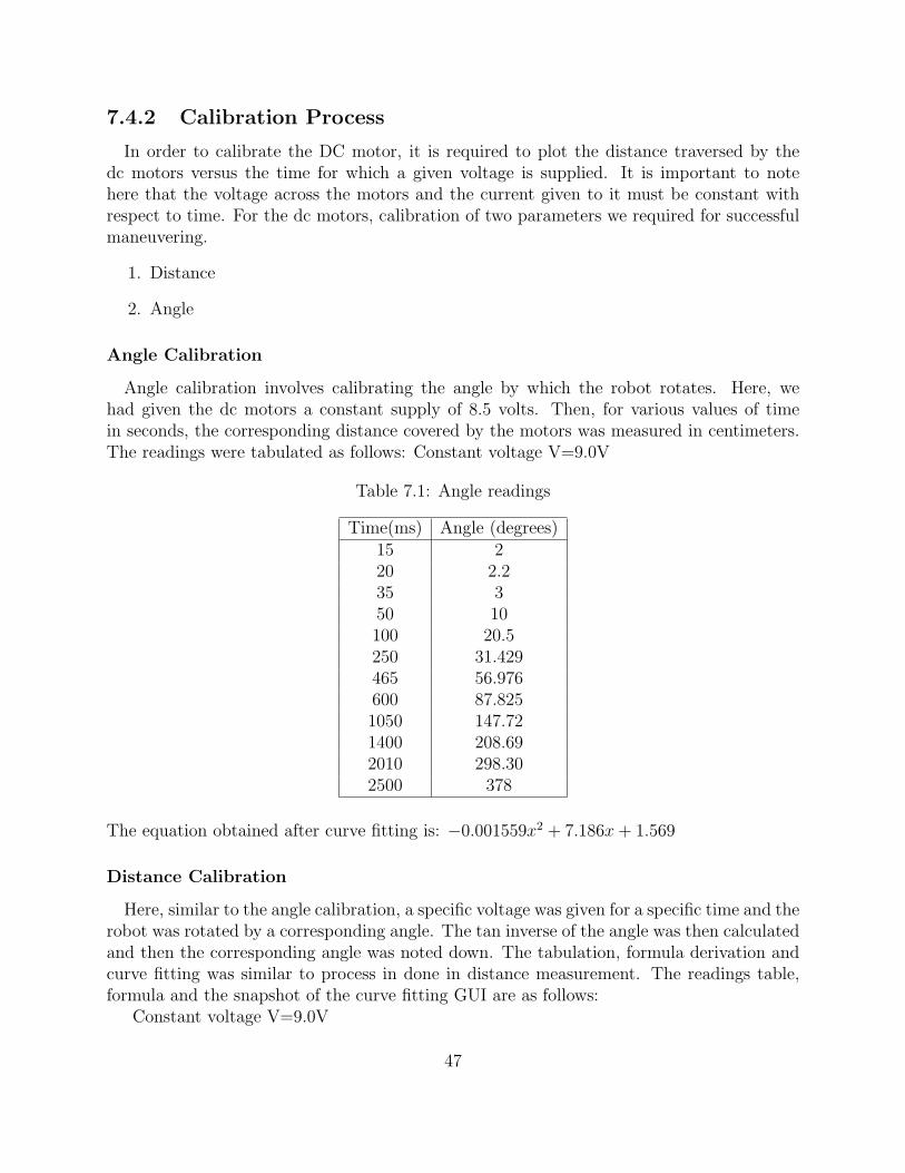
7.4.2 Calibration Process
In order to calibrate the DC motor, it is required to plot the distance traversed by thedc motors versus the time for which a given voltage is supplied. It is important to notehere that the voltage across the motors and the current given to it must be constant withrespect to time. For the dc motors, calibration of two parameters we required for successfulmaneuvering.
1. Distance
2. Angle
Angle Calibration
Angle calibration involves calibrating the angle by which the robot rotates. Here, wehad given the dc motors a constant supply of 8.5 volts. Then, for various values of timein seconds, the corresponding distance covered by the motors was measured in centimeters.The readings were tabulated as follows: Constant voltage V=9.0V
Table 7.1: Angle readings
Time(ms) Angle (degrees)15 220 2.235 350 10100 20.5250 31.429465 56.976600 87.8251050 147.721400 208.692010 298.302500 378
The equation obtained after curve fitting is: −0.001559x2 + 7.186x+ 1.569
Distance Calibration
Here, similar to the angle calibration, a specific voltage was given for a specific time and therobot was rotated by a corresponding angle. The tan inverse of the angle was then calculatedand then the corresponding angle was noted down. The tabulation, formula derivation andcurve fitting was similar to process in done in distance measurement. The readings table,formula and the snapshot of the curve fitting GUI are as follows:
Constant voltage V=9.0V
47
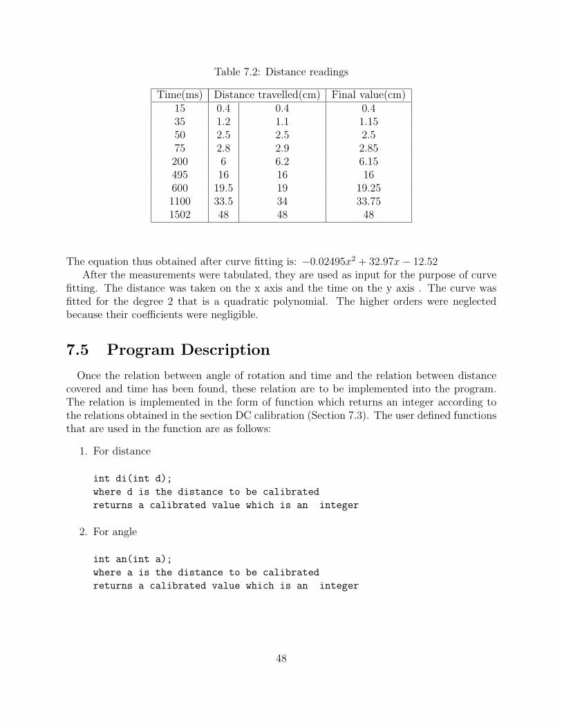
Table 7.2: Distance readings
Time(ms) Distance travelled(cm) Final value(cm)15 0.4 0.4 0.435 1.2 1.1 1.1550 2.5 2.5 2.575 2.8 2.9 2.85200 6 6.2 6.15495 16 16 16600 19.5 19 19.251100 33.5 34 33.751502 48 48 48
The equation thus obtained after curve fitting is: −0.02495x2 + 32.97x− 12.52After the measurements were tabulated, they are used as input for the purpose of curve
fitting. The distance was taken on the x axis and the time on the y axis . The curve wasfitted for the degree 2 that is a quadratic polynomial. The higher orders were neglectedbecause their coefficients were negligible.
7.5 Program Description
Once the relation between angle of rotation and time and the relation between distancecovered and time has been found, these relation are to be implemented into the program.The relation is implemented in the form of function which returns an integer according tothe relations obtained in the section DC calibration (Section 7.3). The user defined functionsthat are used in the function are as follows:
1. For distance
int di(int d);
where d is the distance to be calibrated
returns a calibrated value which is an integer
2. For angle
int an(int a);
where a is the distance to be calibrated
returns a calibrated value which is an integer
48
7.6 Embedded Programming
The robot is controled by the microcontroller, Atmega328. The programming of themicrocontroller is done in Arduino IDE(developed on Java). The programming of Arduinois similar to C language and is also similar to Codevision environment. The syntax is notthe same as many embedded programming environment. The syntax is explained in section5.4. The programming is then converted to C language by adding main() to the createdprogram. The IDE also allows to programming in the manners used by other EmbeddedProgramming Environment like CodeVision.
7.6.1 Programming the Microcontroller
The microntroller is programmed using USB interface. The programming board calledArduino USB board has a FTDI chip which assists in USB communication with the micro-controller. The FTDI chip helps to migrate to USB by combining USB-Serial communicationusing FT232 chip.
The facility of USB programming was one of the reason why Arduino board was chosenfor the project.
7.6.2 Robot Programming
The program of the microcontroller need to take care of the following major operationthat robot has to perform:
• Ensuring data sent by the touch system is received
• Decoding the data
• Turning the motor on or off
Data communication
As there is only a pair of Zigbee modules involved in the system, the communicationbetween them can be carried out using usual serial transmission and reception commands. Ifthe number of modules involved are more then it may become necessary to use AT commandsto ensure proper communication.
The data that is transmitted by the touch system is byte-by-byte communication. Forexample, if a string ”ab” is to be transmitted, first ’a’ will be received and the ’b’ will bereceived. The data that received can be stored as an integer or a char. In case of integer anASCII value is stored.
The data, distance and angle, was transmitted using the following format:
dDistance,aAngle.
where Distance is an integer value
Angle is an integer value
49

When the data is received is received following steps are taken:
1. The byte is checked for the type, that is, numder or alphabet or special character
2. If it is an alphabet, then number following it is stored as in respective variable toindicate angle or distance
3. A comma(,) indicates the current data, distance or angle, has been completely trans-mitted
4. A fullstop(.) indicates the a complete set, distance and angle, has been transmittedand the motor should run in that direction.
Motor control
Once data has been received the motor is turned on for a particular period of time. Thisvalue is same as the alue received by the microcontroller. After every forward, right or leftoperation the motor is stopped for a minimum of 100ms to nullify the effect of the momentumgained by the motor.
50

Chapter 8
Results and Conclusion
This chapter discusses the various results related to marker detection, wireless communi-cation, Multi touch table and its components. The final section draws a conclusion basedon the proposed system and the final outcome of the project.
Results
The result of the final year project are as follows:
1. Marker Detection:During the course of the project we have tried different markers. Some of them havebeen shown below: All these marker gave satisfactory result for the purpose of robot
(a) Original Camera (b) Opened camera
Figure 8.1: Different markers
detection. The problem in detection arises when the lighting condition are not good.The detection process is affected by very low intensities and very high light intensities.
The quality of camera also plays an important role in the marker detection process. Thecamera we tested includes Microsoft VX-3000, HP camera, Sony PS3Eye and LogitechQuickCam. Out of all these PS3Eye gave the best result. It was least affected bylighting condition and the calrity was superior as compared to other camera. The
51

result of marker detection with respect to various angle are shown below:As can be seen from the above list of snapshots that the marker is detection gives a
(a) (b) (c) (d) (e) (f) (g)
(h) (i) (j) (k) (l) (m) (n)
Figure 8.2: Marker detection in different orientations
satisfactory results.
2. Wireless Communication:The communication between Multi touch System and the robot involved continuoustransmission of data set, which contain distance to be covered and angle through whichthe robot is to be rotated.
The process of implementing(rotating the motor) the decoded data requires maximumof around 2 seconds. Thus, there is a possibility that the transmission or receptionbuffer will overflow. During the experimentation with different sets of data, we foundthat if number of data sets is greater than 10, then there is a possibility that the dataset and the consecutive data sets will not be implementated. This happens becausethe default buffer size in the serial library is 128 bytes. The format described insection 7.6.2 can lead to data set of maximum size 12 byte which inturn correspondsto maximum of 10 data set at a time.
The solution to this problem was to either increase the buffer size or involves handshaking signal between robot and multi touch system.
The Xbee communication was successfully tested to send and received data to andfrom about more than 10m.
3. Multi Touch System
(a) IR LedWe have tested led of wavelength 850nm and 940nm. The IR camera uses floppydisk as a visible light filter. During the testing process, the 940 nm led did notgive satisfactry result as the detection of blob was difficult and a lot of pressurehad to be applied in order to create a touch point. But as compared to 940nmled 840nm led requires less pressure to create a blob.
52

(b) Compliant surfaceIn order to reduce the presure required to reduce a touch point compliant surfaceis used. The compliant surface is a projection surface(tracing paper)coated withmixture of clear silicon sealent and thinner. As the number of coating of thismixture increases, the sensitivity of the touch surface improves.
(c) MirrorThe projection from the projector is first incident on the mirror. This step helpsin reducing the height of the touch table. But the thickness of the mirror playsan important role in the quality of image displayed on the projection surface.Because of reflection taking place from surface of the mirror the quality of theimage on the projection screen is distorted. Thus, greater the thickness better isthe visibility of two distinct images and thus weaker is the quality of image.
We tested the quality with a 5mm and 3mm thick mirror. The 3mm thick mirrorgave clear and best result among the two.
4. Robot movement
(a) To maintain the calibration of DC motors it is imperative to give constant DCsupply to the motors. If the DC supply is varied ±0.5V then the calibration isnot affected.
(b) During the testing, robot was moved through various angle and we found thatfor angle above 90 the robot did not obey the calibration equation. The errorin calibration increased as the angle increased toward 360. We found that thishappened due to the momentum gained by the DC motor during the on time.Thus, the movement of the robot was restricted to a maximum of 180.
Figure 8.3: Difference between traced and original path
53

(c) The smooth path of our fingers is broken into series of straight line motion foreasy dc motor control. Hence we do not get a smooth path. The path is createdby sampling the position of our fingers. If we take low sampling period we getmore points and hence better reconstruction, however the Atmega328 has limitedbuffer space and hence large number of points will result in data overflow andhence, data loss. Hence we use the maximum sampling points that shall notcause buffer overflow. The figure 8.3 illustrates the idea. This figure is a snapshotof the program that the group has created.
Conclusion
The proposed system for the final year project was to design a touch based system thatenables to control one or more robot using wireless communication.
We have succesfully implemented a PC based Multi Touch System and a Wireless robot.We have test and interfaced wirelessly one robot with the multi touch system. Though wehave not interfaced more than two robots to the Mult touch System but we have been ableto detect two distinct marker at the same time.
We have also created some basic and intermediate level touch applications and a touchpresentation in Java.
Though the proposed system is partially fulfilled but the PC based Multi Touch Systemhas been succefully implemented. The system is called as low cost because total cost involvedin the creating this system excluding the projector is around Rs. 6000. This is cheapcompared to the capacitive touch screens available in the market of the same dimension.
54

Appendix A
Additional Programs and ProjectPictures
1. Sine wave
(a) (b)
Figure A.1: Snapshot of two different sine wave related programs
This program was created with an intention to show how the touch interface canimprove the quality of interaction with a compute system. The program recognizesa straight line gesture and creates a sine wave whos amplitude and frequency can bechanged using touch gestures. The natural user gesture like moving the finger upwardson the screen increases the amplitude or moving it down decrease the amplitude. Sim-ilarlly, moving the finger toward right or left increases or decreases the frequency
2. Touch PresentationThis was the program created specifically for the project presntation. The presentationis controlled by single touch and multi touch gesture[11]. These geture are designed tohelp the user move from one slide to another. The presentation gives an idea of thevarious section of the project.
55

(a) (b) (c)
Figure A.2: Snapshot of the Presentation
3. 3DThis program can be used to control the orientation of a box. The box can be rotated
Figure A.3: Snapshot of program playing with box
in x,y or z direction using the touch points.
4. Photo applicationThe photo application perform the drag and drop operation. It also ha the ability to
Figure A.4: Snapshot of photo application
zoom in and zoom out of a particular photo using two fingers.
There are various possibilites and application possible with multi touch system[9].Developers have been developing games like pong which is a multi player game. pongis a flash game. Multi touch programming and game development can be done onvarious platforms and using verious textual and visual programming languages like C,C++, Java, vvvv and many more.
56

5. Some Project PicturesThese snapshot indicates the actual robot, the overhead camera and user drawing the
(a) (b) (c) (d)
Figure A.5: Snapshot of the Project
path for the robot to move on. These snapshots are the inside and the outside view of
(a) (b) (c)
(d) (e)
Figure A.6: Snapshot of Arrangement of Touch Table
the multi touch table. It also shows the arrangment of various componenets describedin the report like mirror, IR camera, XBee module and Touch sensor.
57
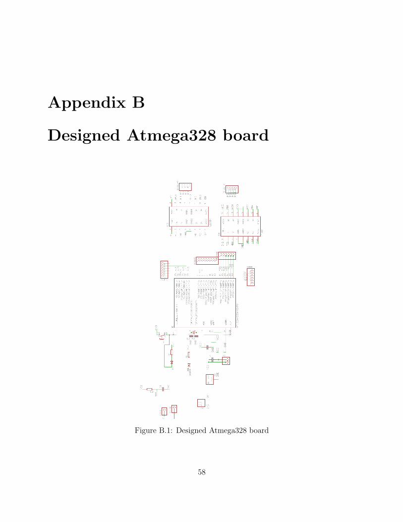
Appendix B
Designed Atmega328 board
Figure B.1: Designed Atmega328 board
58
Bibliography
[1] Uwe Hahne, Marc Alexa, Bjorn Bollensdorff, Ingo Bressler, Stefan Elstner,2008,A FTIRbased Multit Touch Table Using Pulsed Illumination for noise Suppression, TU Berlin
[2] D.Michl, A.A.Argyos, D. Grammenos, X. Zabulis, T. Sarmis, 2009, Building a multi-touch display based on computer vision techniques Institute of Computer Science,Greece
[3] Christopher Wolfe, J. David Smith and T.C. Nicholas, A Low Cost Infrastructure forTable Top Games Graham School of Computing, Canada
[4] Philip L.Davidson, Jefferson Y. Han,Synthesis and Control on Large Scale Multi-TouchSensing Displays , New York University
[5] J. David Smith,T.C. Nicholas Graham,Low-Cost Malleable Surfaces with Multi-TouchPressure Sensitivity , School of Computing, Queens University
[6] Jefferson Y. Han, 2005, Low-cost multi-touch sensing through frustrated total internalreflection, UIST ’05
[7] Jefferson Y. Han, 2006, Multi-touch interaction wall, ACM SIGGRAPH 2006 Emergingtechnologies, Boston, Massachusetts
[8] TODD BISHOP, May 2007,Microsoft Surface brings computing to the table,http : //www.seattlepi.com/business/317737msftdevice30.html
[9] Bradley H. Hayes, 2008, Software Driven Multi Touch Input Display as an Improved,Intuitive, and Practical Interaction Device, Undergraduate Honors Thesis ,ComputerScience Department, Boston College
[10] Microsoft Co., 2008, Microsoft Surface, http://www.surface.com
[11] Micheal Thornlund, 2007, Gesture Analysizing for Multi touch screen interface, LueaUniversity of Technology
[12] B. Buxton, Multi-Touch Systems that I Have Known and Loved,http://www.billbuxton.com/multitouchOverview.html
[13] William C. Crai, Spring 2008, Zigbee: Wireless Control that Simply Works, ProgramManager Wireless Communications, ZMD America
59

[14] NUI Group Authors,1st edition [Community Release]: May 2009, Multi-Touch Tech-nologies
[15] Sudhanshu, Rahulmotiyar, CHEAP AND EASY COMPLIANT SURFACE, TeamSparsh,www.sparsh-i.com,India
[16] Brian W. Evans, Arduino Programming Notebook
[17] OSRAM Opto Semiconductors, SFH 485P Datasheet, http://www.osram-os.com
[18] www.ardunio.cc, Official website for Open Source Arduino Hardware
[19] www.processing.org, Offical website Processing environment and language
60