PBS User’s Guide - University of California, Santa...
42
1 PBS User’s Guide Version 2.2 F. Brewer, A. Crews, A. Seawright
Transcript of PBS User’s Guide - University of California, Santa...
1
PBS User’s Guide
Version 2.2F. Brewer, A. Crews, A. Seawright

2 PBS User’s Guide
3
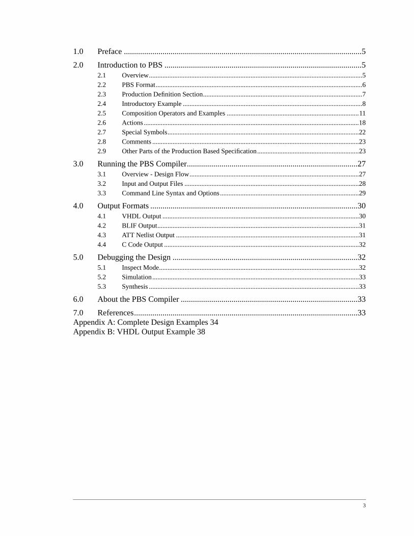
1.0 Preface .....................................................................................................................5
2.0 Introduction to PBS .................................................................................................52.1 Overview..............................................................................................................................5
2.2 PBS Format..........................................................................................................................6
2.3 Production Definition Section..............................................................................................7
2.4 Introductory Example ..........................................................................................................8
2.5 Composition Operators and Examples ..............................................................................11
2.6 Actions ...............................................................................................................................18
2.7 Special Symbols.................................................................................................................22
2.8 Comments ..........................................................................................................................23
2.9 Other Parts of the Production Based Specification............................................................23
3.0 Running the PBS Compiler....................................................................................273.1 Overview - Design Flow....................................................................................................27
3.2 Input and Output Files .......................................................................................................28
3.3 Command Line Syntax and Options..................................................................................29
4.0 Output Formats ......................................................................................................304.1 VHDL Output ....................................................................................................................30
4.2 BLIF Output.......................................................................................................................31
4.3 ATT Netlist Output ............................................................................................................31
4.4 C Code Output ...................................................................................................................32
5.0 Debugging the Design ...........................................................................................325.1 Inspect Mode......................................................................................................................32
5.2 Simulation..........................................................................................................................33
5.3 Synthesis ............................................................................................................................33
6.0 About the PBS Compiler .......................................................................................33
7.0 References..............................................................................................................33Appendix A: Complete Design Examples 34Appendix B: VHDL Output Example 38

4

Using the PBS Synthesis System 5
Using the PBS Synthesis System
Version 2.2 Guide & Reference
Andrew Seawright, Andrew Crews, Forrest BrewerDepartment of Electrical and Computer Engineering
University of California, Santa Barbara
1.0 Preface
PBS stands forproduction-based specification. This guide and reference describes thePBS format and a tool that compiles designs specified in this format.
This tool was developed at the University of California, Santa Barbara Department ofElectrical and Computer Engineering. The project that led to its development was madepossible through the generous support of Synopsys Inc., the California Micro Program,and the National Science Foundation. This documentation is Copyright 1997 by TheUniversity of California. It may be freely distributed as long as it is distributed in completeform with this copyright notice. Originating work was performed by Andrew Seawright,optimization algorithms and extensions were made by Andrew Crews, both under thedirection of Forrest Brewer.
2.0 Introduction to PBS
2.1 Overview
The use of high-level and hardware description languages is now widespread in the speci-fication, verification, and synthesis of digital hardware. These languages allow the abstrac-tion of circuit-level details in the design process and enable design specification at the“algorithm-level”. High-level language specification provides numerous advantagesincluding increased design productivity, technology independence, and greater reuse ofdesign specifications.
PBS addresses the specification, design, and optimization of certain types of complex con-trol-dominated designs. For the most part, conventional hardware description languages inuse today model behavior in a procedural fashion similar to a procedural programminglanguage. In a procedural style, the control flow of the design is specified explicitly.Description of control flows typically use branching constructs such asif-then-else andcase statements, which may be functions of explicitly specified control state variables.Design systems using this kind of specification have become commercially available andare successful tools. However, for a class of problems, the specification of the machine

6 Using the PBS Synthesis System
behavior in this format is unnecessarily lengthy and complex. This is especially true forproblems in which the time sequence behavior is complex, in that the control state space islarge or difficult to describe explicitly (e.g. protocol decoders, communication devices,computer interface subsystems).
An alternative to a procedural specification style is an applicative or declarative style inwhich the legal behaviors of the design are described through a hierarchical compositionof the legal sub-behaviors. The salient characteristic of thisProduction-Based Specifica-tion (PBS) is its implicit representation of the control flow of the design, in an applicativedesign style.
This applicative style of specification is intended to avoid some of the problems associatedwith explicit description of the control flow. An applicative style, for instance, does notnecessarily require encoding of control states and state transition in the high level descrip-tion, as may be required in procedural design style. Additionally, procedural specificationsof complex, control-dominated design can be error-prone since, in general, the resultingdescriptions are correspondingly complex, while applicative style descriptions often donot suffer from this problem. Finally, incremental modifications of a design described inan applicative style are much less likely to require large global changes of the design, asmay occur in procedural styles.
The essential idea behind PBS is to represent the control structure of the design using ahierarchical set ofproductions. These productions describe the desired “protocol” at thehigh-level, and “recognition” of these productions effect appropriate actions.
Designs specified in PBS are really design entities. These design entities are assumed tointeract with other design entities, which may or may not be specified using PBS, as com-ponents of a larger system. PBS format is compatible with the VHDL [1] design method-ology and is intended to be used by the designer as an alternative specification style usedin conjunction with other specification and design methods.
The compiler also supports other options for encoding the controller mechanism in a non-code generation mode. In this mode, the resulting controller is written out as a BLIF orATT format file with latches and an appropriate reset state. In this mode, actions have asymbolic meaning and are currently not-hot encoded. Extensions to allow output encodingin the language and moore-based persistent outputs will be available soon.
2.2 PBS Format
The PBS specification is a single file comprised of three parts. The first part is called the“environment and support” section. This section contains information about the interfaceof the design, supporting VHDL code, construction and compilation directives, and defini-tions and declarations to support action clauses in the productions. The second part of thePBS specification contains the declaration of the input signals, productions, markers, and

Using the PBS Synthesis System 7
declared actions used in the production section. These declarations simplify the task ofcorrect compilation analysis and eliminate the problems of predefined key-words. The lastpart of the specification consists of a collection of productions describing the behavior ofthe design entity. Since this third part is the most important part of the specification, wefocus on it first.
2.3 Production Definition Section
2.3.1 Overview - Productions, Operators, and Actions
A production is a named composition of symbols, operators, and action clauses. There aretwo kind of productions, those for building up sequential behaviors, and those construct-ing combinational Boolean functions. The symbols in asequential production are eithertokens or references to other sequential productions. A token is a reference to a Booleanproduction in a sequential production. The symbols in a Boolean production are either ref-erences to other Boolean productions or atomic symbols. Atomic symbols are Booleanfunctions of input interface signals and marker evaluations or are language defined sym-bols.
Several different types ofcomposition operators are used to compose the productions, andthey are used to build more abstract or complex productions from simpler productions. Forexample, they create productions of more complex behaviors from productions of simplerones. The composition operators are similarly grouped into sequential and combinationaltypes for use in the two kinds of productions.
environment and support
input signal declarations
productions
Figure 1.
PBS file

8 Using the PBS Synthesis System
A token is “accepted” or “recognized,” if its Boolean function is satisfied in the cycle thetoken is referenced through execution of the productions. A production is accepted whenthe time sequence of behaviors dictated by itscomposition is satisfied. Symbols, composi-tions, and productions are annotated withaction clauses, or actionsfor short. Basically, anaction is a specified data-flow behavior which is executed when its antecedent (symbol,composition, or production) is recognized.
2.4 Introductory Example
A set of productions are shown below. There are five productions in this description:
mouse, event , forward, reverse and rising . All are sequential productionswith forward andreverse events initialized simultaneously. The symbolsxc andxdare input signals from the interface to the external world. The first production in a set ofproductions, in this case themouse production, is called thetop-level production. Thetop-level production encompasses the behavior of the whole design. Other than the toplevel production, all production may occur in any order.
This set of productions implement a mouse position decoder machine, which continuouslyupdates the variablex with a current 1-dimensional position based on the quadratureencoding of the signalsxc andxd from external motion sensors. The position is updatedif the productionsforward or reverse are recognized. Due to the structure in this
<right> <left> <no move>
xc
xd
x = 42 x = 43 x = 42x
Figure 1.
mealy {}::#input xc xd#production mouse event forward reverse rising::mouse -> .*, event;event -> forward || reverse;forward -> (xd):rising; [ x <= x + 1; ]reverse -> (~xd):rising; [ x <= x - 1; ]rising -> ~xc+, xc;::

Using the PBS Synthesis System 9
example, these productions could be recognized, starting from any present state of themachine. In general, several productions may be recognized or be in the process of recog-nition simultaneously. The bottom portion of the figure shows an example of the timesequence behavior of this design.
PBS specifications describe synchronous designs where behavioral changes are synchro-nized to transitions on global clock signals. In the timing diagram in Figure 1, the clock isnot shown, however at least one clock is always assumed. Synchronous token recognitionprovides the atomic mechanism for the time sequence behavior of a design.
The syntax of a production is as follows:
<production identifier> -> <production composition>; [action]
This syntax is based on the Backus-Naur Form (BNF) [3] used to describe language gram-mars. Theproduction identifier is a unique name labeling the production. This name canbe used in other productions to refer to it. Theproduction composition contains the sym-bols, composition operators, and actions defining the meaning of the production. The pro-duction composition is terminated with a semicolon, however, it is possible to place anaction list after the semicolon, in which case the actions are referenced to the productionidentifier.
The symbols in the production composition mayreference other productions. When a pro-duction composition references another production, by its identifier name, it is just as ifthe referenced production’s composition was substituted in place of the identifier name.Production referencing has several advantages: it allows decomposition of design behav-ior into logical portions, it allows for more efficient descriptions through sharing and reuseof productions, and it provides more flexibility in the placement of actions.
When productions reference other productions among the collection of productions, thisreferencing may not be recursive. In a recursive set of productions, the production refer-encing contains at least one cycle. This means that the hierarchical composition of thedesign cannot be described using a directed-acyclic graph (DAG). Productions are notallowed to be recursive because one can’t guarantee, in general, that the specification is ofa finite machine1 (machines not requiring an arbitrary amount of memory storage [3]).Recursion in software specification is essential for the description of language grammars,which are typically push-down or LALR automata. However, PBS is oriented specificallyfor the hardware domain where we are interested in describing the behavior of finitemachines (FSM’s, controllers, protocols), and recursion is not essential, nor necessarilyefficient. One type of behavior commonly modeled by recursion is the use of non-localreferencing in which the recognition of a production might depend on the coincident rec-
1. Although tail recursion does not jeopardize the finite machine requirement, it is still not allowed. This isnot a problem, since tail recursive behavior can be concisely described using the Kleene Closure operator“* ”.

10 Using the PBS Synthesis System
ognition of an unrelated production. In PBS, this behavior is achieved using amarker,which is a special type of internal action that creates a Boolean signal. Since this signalcan be used to enable production recognition, this behavior is easy to achieve.
If a PBS specification contains recursion, an error will be generated at compile time indi-cating the line number of the first occurrence of the production recursed. For example, thefollowing set of productions is recursive:
a -> b || c, b;b -> ~x & z;c -> a, b;
If compiled, the error would indicate recursioninto the production on the first line.
In the mouse example, the sequential operators: “, ”, “ * ”, “ +”, and “|| ”, are extensions ofthe classical Regular Expression operators, and the operators: “: ” and “~” are Booleanoperators, (“:” allows a Boolean token to qualify a production). These operators and othersare tabulated on the next page in Table 1. Each of the operators will be described in detaillater.
As mentioned earlier, there are two types of productions: Boolean and sequential produc-tions. There are Boolean and sequential composition operators, as well. With the assump-tion of non-recursive productions, the following statements apply.
• A Boolean composition contains only Boolean composition operators and references toBoolean productions.
• A sequential composition must contain at least one sequential composition operator orat least one reference to a sequential production.
• Sequential productions can be referenced from sequential compositions.
• Boolean productions can be referenced from Boolean compositions.
• Boolean productions can be referenced from sequential compositions, and when donethis reference is areference to a token.
• Sequential productions cannot be referenced from Boolean compositions.

Using the PBS Synthesis System 11
2.5 Composition Operators and Examples
In this section, the various composition operators will be described. These composition
operators are tabulated in Table 1 above. In this table,<comp> refers to a sequential com-position or a sequential production reference or a token reference.<bool-comp> refers toa Boolean composition or a Boolean production reference. Finally,<int> refers to an inte-ger argument.
2.5.1 Sequential Operators
When a composition involves a sequential operator, the operator is recognized (accepted)if its composition operands satisfy some requirements based on the type of operator.
2.5.1.1 Concatenation “, ”
The concatenation operator concatenates the behavior of its two composition operandstogether in time sequence. It is helpful to view these composition operands as sub-machines. The acceptance or recognition of the concatenation of two sub-machines occursif the first sub-machine is started and is recognized immediately, followed by the initiationand acceptance of the second sub-machine. For example, in the production:
TABLE 1. Composition Operators
operator name type usage
, concatenation sequential <comp> , <comp>
^ multiple concatenation sequential <comp> ^ <int>
|| sequential or sequential <comp> || <comp>
&& sequential and sequential <comp> && <comp>
! sequential not sequential ! <comp>
* Kleene Closure sequential <comp> *
+ one-or-more sequential <comp> +
!! exception-handler sequential <comp> !! <comp>
!R exception-reset sequential <comp> !R
!E exception-excitation sequential <comp> !E
| Boolean or Boolean <bool-comp> | <bool-comp>
& Boolean and Boolean <bool-comp> & <bool-comp>
^ Boolean exclusive-or Boolean <boo1-comp> ^ <bool-comp>
~ Boolean complement Boolean ~ <bool-comp>
: qualification special <bool-comp> : <comp>
x(2) delay special <marker-identifier>( <int> )

12 Using the PBS Synthesis System
p -> a, b;
p is recognized if thea sub-machine is recognized, followed by the initiation and recogni-tion of b. Here,a andb are defined by other productions and compositions. The concate-nation operator is used to build behaviors responding to activities occurring in order.Three additional examples are:
frame -> start_bit, data_bits, stop_bit;
three_blocks -> start_block, middle_block, end_block;
instruction -> op_code, operands;
2.5.1.2 Multiple Concatenation “̂ ”
Multiple concatenations of the same composition a fixed number of times can be specifiedusing themultiple concatenationoperator. This operator concatenates the left hand sidecomposition operand an integral number of time specified by the right hand argument. Forexample in the production:
byte -> bit^8;
abyte is the recognition of eightbit ’s in a row. This operator is a convenient shorthanduseful for cases where using the previous concatenation operator would be tiresome. Forexample, the following production is the long way to write the same behavior as the pro-duction above.
byte -> bit, bit, bit, bit, bit, bit, bit, bit;
Since PBS specifies a chain of flip-flops for these kind of constructions, rather than usingencoded counters, for example., it can be very useful to perform factoring on multiple con-catenation constructions. Placing parenthesis around the integer indicates that the produc-tion should be considered for sequence factoring by the compiler. The implementation ofsequence factoring is not defined, only that the behavior is equivalent.
byte -> bit^(8);
2.5.1.3 Sequential Or Operator “|| ”
Thesequential oroperator is used to specify a choice of desired behaviors. The recogni-tion of the left hand composition operandor the right-hand composition operandor bothwill cause the acceptance of the two-wayor composition. For example:
word -> control_word || data_word;

Using the PBS Synthesis System 13
If active, recognition of the productionword will occur if control_word is recognizedor data_word is recognized. Some more example productions using “|| ” are:
event -> left || right; // from the mouse example
block -> a_block || b_block || c_block; // three-way or
message -> x^12 || y^8; // or used with other operators
foo -> (bar, baz) || q; // or used with other operators
The sequential or operator, as well as thesequential and operator, described next, buildconcurrence into the design.
2.5.1.4 Sequential And Operator “&&”
A composition containing thesequential and operator is recognized when its left handcomposition operandand its right hand composition operand are recognized at the sametime (in the same cycle). This operator can be used for synchronization. For example, inthe following production:
p -> event1 && event2;
p is recognized only ifevent1 andevent2 are recognized together in the same cycle.To expand on this example, replace theevent1 andevent2 references with the compo-sitions(~x+, x+) and(~y+, y+) :
p -> (~x+, x+) && (~y+, y+);
wherex andy are interface signals. The composition(~x+, x+) is recognized if a ris-ing edge is “seen” on the signalx (see descriptions of the operators “+” and “~”). Simi-larly, (~y+, y+) recognizes a rising edge on the signaly. The compositions replacingevent1 andevent2 were “built” to continuously accept after the rising edge on theirrespective signals, so long as the signals remain high. Thus, the productionp is recognizedonly if a rising edge occurs on bothx andy. These rising edges may arrive in either orderor in the same cycle. One final note, the productionp will continue to be recognized aslong as the signalsx andy remain high.
2.5.1.5 Kleene Closure Operator “* ”
The Kleene Closure operator is an operator for the specification of variable sequences.Specifically, zero or more concatenations of the operand composition will be recognized.For example in the production:
p -> a*, b;

14 Using the PBS Synthesis System
zero or morea’s followed byb will cause the recognition ofp. For example, the followingsequences will all be recognized: {b, ab, aab , aaab , ... }. Here,a andb could be tokensor behaviors based on other productions.
A common use of the Kleene Closure operator is with the special symbol “. ” (describedlater). For example, in the production:
p -> .*, x; // any sequence ending with x.
The behavioral idiom “.*, x ” means “anything followed byx” or “anything ending withx”, wherex could be a token, a composition, or another production. Note that, “anythingending inx” describes sequences that may contain embeddedx ’s, e.g. “abxbaxxx ”. Thisbehavioral idiom is used in the top-level production of the mouse example. The mouserecognizes “any previous encoder sequence followed by an event”. In general, composi-tions and productions using the “* ” operator and the “+” operator (described below) havethe property that they recognize repeatedly, or describe periods of continuous recognition.
2.5.1.6 One or More Operator “+”
The “+” operator is similar to the Kleene Closure operator, however, compositions involv-ing it recognizeone or more concatenations of the operand composition. The composition“x+ ” is equivalent to “x, x* ” and “x*, x ”. However, it is far more efficient to use “+”than the concatenation since “+” creates one control point in the worst case. For example:
p -> ~x+, x; // p recognizes a rising edge on the// interface signal x
p -> ~x+, x+; // p recognizes a rising edge on x,// and continuously recognizes if// x remains high
2.5.1.7 Sequential Not “! ”
Thesequential not operator is used to invert the state of recognition of its single composi-tion operand. The operator is in a state of recognition only if its composition operand isnot in a state of recognition. For example, recognition will occur if: the operand composi-tion has not yet been initiated, it was initiated but is not yet accepting, or was initiated andwill never accept. This operator is useful in certain special cases, such as in, the followingproduction:
p -> !(.*, a, a, .*); // accept any sequence without// two a’s in a row
This production recognizes any sequence not containing twoa’s in a row. Thea’s couldbe tokens or behaviors described by other productions.

Using the PBS Synthesis System 15
2.5.2 Overview - Exception Operators - “!! ”, “ !R ”, and “ !E ”
Exception operators are useful for specifying exception handling, recovery, and re-syn-chronization mechanisms as well as closing incomplete specifications. These operators areused to specify behaviors based on the conditions in which other behaviors, or sub-machines, enter states from which they cannever accept. In a sense, behaviors can be afunction of what is not described by a composition or production. This allows access tothe complement space of compositions or productions. These operators are similar to thesequential not operator, described above, however, the exception operators describebehavior solely in terms of the conditions in which other behaviors enter states fromwhich they cannever accept. Precisely, if the subject composition describes a set ofacceptable event sequences, an exception will accept on any event sequence which willleave the set on the next cycle.
2.5.2.1 Exception Operator with Handler “!! ”
If a composition of this operator is initiated, execution begins with the left-hand composi-tion sub-machine. If this sub-machine is about to enter a state from which it can neveraccept, in the next cycle, this operator will cause the initiation of another sub-machine,called thehandler, specified by the right-hand composition operand. If the handler sub-machine accepts, the machine behaves exactly as if the left hand machine accepted, andthe complete composition is recognized. For example, in the production:
data -> data_block!!handler_machine;
the data production will be recognized ifdata_block is recognized,or if the dat-a_block sub-machine enters a state from which it can never accept, followed by theacceptance of the initiatedhandler_machine sub-machine. The “!! ” operator, as wellas the other exception operators, can be nested. For example, the composition of thehan-dler_machine may contain imbedded exception handlers.
2.5.2.2 Exception Reset Operator “!R ”
Initiation of a composition containing the “!R” operator begins with the execution of themodified operand sub-machine. The exception reset operator, will re-initiate (reset) thesub-machine if, in the next cycle, it will enter a state from which it can never accept. Inother words, the operand sub-machine is constructed normally except that instead of enter-ing an end state from which it can never except, it resets, and behaves as if it had not yetbeen initiated. If the operand composition sub-machine does accept, the complete compo-sition accepts. This operator is useful for behaviors that “abort back to the beginning untilthey are satisfied.” For example, in the following production:
message -> preamble!R, body, tail;

16 Using the PBS Synthesis System
when themessage sub-machine is initiated, recognition of apreamble will beattempted. If thepreamble can’t be recognized for some reason, thepreamble sub-machine will be restarted.Once the composition “preamble!R ” recognizes the first validpreamble present in the input data stream, execution will continue with the initiation ofthebody sub-machine.
2.5.2.3 Exception Excitation Operator “!E ”
A composition with “!E” is accepted only when the sub-machine built from its composi-tion operand will go into a state from which the sub-machine will never accept in the nextcycle. This operator is similar to the sequential not operator except that the sequential notoperator does not distinguish between the cases of “not currently accepting” and “willnever accept”.
2.5.3 Boolean Operators “&”, “ | ”, “ ~”, and “ ^ ”
The Boolean operators:Boolean and “&’, Boolean or “|”, Boolean not “~”, andBooleanexclusive-or “^ ”, are used in Boolean compositions for specification of Boolean functions.Boolean functions are used astokens in sequential productions and used as the left-handoperand in the qualification operator described in the next section. Note, the operator “^ ”has two meanings, i.e. it is anoverloaded operator. The symbol “̂ ” is also used for thesequential multiple concatenation operator. The meaning is never ambiguous since theright-hand operand distinguishes between the two cases, e.g. if it is an integer it must bethe sequential concatenation operator. The following production is a Boolean productionfrom the mouse example:
A -> xc & ~xd;
2.5.4 Qualification Operator “: ”
A sequential production or composition may bequalified with a Boolean production orcomposition using the specialqualification operator. The qualification operator modifiesthe sequential behavior of the right-hand sub-machine operand with the Boolean functionrepresented by the left-hand Boolean composition operand. The behavior of the qualifiedsub-machine is the same as that of the unqualified sub-machine, except that, in order forthe qualified sub-machine to be recognized, the Boolean function qualifying the sub-machine must remain true throughout the sub-machine’s execution. In other words, thebehavior of the qualified sub-machine is the same as the unqualified sub-machine in whichall of its token functions have beenanded with the qualifying function.
The qualification operator is useful because it can modify or refine the behavior of a pro-duction for different contexts. For example, a “generic” sub-machine can be specified. Thesub-machine’s production identifier can be referenced from several other productions indifferent contexts, and its behavior can be refined through qualification. This allows con-

Using the PBS Synthesis System 17
cise specification for many cases. For example, consider the following excerpt of five pro-ductions:
...frame -> start_bits, data_bits, stop_bit;data_bits -> mode1:bit^7 || mode2:bit^8;mode1 -> x0 & ~x1;mode2 -> ~x1 & (x1 | x2);bit -> zero || one;...
These productions describe a portion of a serial asynchronous receiver protocol, definingthe makeup of a valid data frame. In this protocol, the number data bits in the frame maybe seven or eight depending on the receiver’s mode. Here, qualification is used to modifythe genericbit sub-machine for the two modes the receiver could be in:mode1 ormode2. The truth of the Boolean productionsmode1 and mode2 reflect the currentmode. They are functions of the signalsx0 , x1 ,andx2 , from, for example, an externalcontrol register. In order for a valid frame to be recognized, seven valid data bits must bereceived with the condition thatmode1 is true throughout,or eight valid data bits must bereceived with the condition thatmode2 is true throughout. The makeup of abit is deter-mined by thebit production elsewhere in the specification.
2.5.5 Delay (Marker) Operator
The delay operator facilitates expansion of the context of a production by allowingimplicit reference to current or past values ofmarkers. A delay is a Boolean operator(returns a Boolean value) whose value is a sample of the acceptance state of the produc-tion to which the marker is attached The sample is referenced from the execution of thecurrent production with a given delay. For example, foo(1) is a Boolean variable which istrue if and only if <foo> marked a production accepted in the previous cycle. Similarly,foo(3) is true iff the production <foo> marked, accepted three cycles ago. The value of adelayed production is defined to be zero if the production has not been in current context.i.e. 1 means accepted, zero means either did not accept or has not been in current context.
Delays can have a reference time ofzero, indicating that the sample is to be taken on theconclusion of thecurrent cycle. In effect, the named productions are retimed to the previ-ous cycle and the resulting mealy edge is made available for use in thecurrent productioncomposition. Clearly, there is a danger here of creating combinational loops and/or incon-sistent logic. However, the power of being able to directly access the current state is agreat convenience. Unfortunately, determining precisely when such an assignment mightlead to inconsistent machine behavior is quite difficult. In current PBS, a check is madewhich warns the user if the compiler suspects that a marker might be used inconsistently.
Delay operators have great utility in certain machine constructions and create a simplemethod for implementing conventional state tables as productions. This use does not alter

18 Using the PBS Synthesis System
the theoretical power of the language -- but can be very expressive in some contexts.Please note however, that sequential complement operations may produce valid but unex-pected behavior if delay operations are used on interior sub-machines. In particular, thereset exception can restart a submachine -- but won’t clear the delayed values of the pro-ductions.
2.5.6 Operator Precedence
Table 2, tabulates the precedences and associations of the various operators. Beginningwith the “|| ” and “!! ” operators, this table runs from lowest to highest precedence,where operators of equal precedence appear on the same line.
These precedences may be overridden by appropriate grouping of terms using parenthesis,as in this example:
mode2 -> ~x0 & (x1 || x2);
2.6 Actions
In PBS there is a partitioning of the design’s behavior between the control-flow, or “proto-col” of the design, and the data-flow computations that are performed in response to theflow-of-control. The control-flow in a PBS specified design is describedimplicitly by thestructure and composition of the production sub-machines. Mainly, it is this implicitdescription of the control-flow that makes this style of specification an attractive alterna-tive to the designer. In order for the designer to “hook-in” to the implicitly described con-trol-flow when specifying the data-flow, both a method and methodology are needed. Theaction clauses and the rules that govern their use serve this purpose.
TABLE 2. Operator Precedence
operators association
|| !! left
&& left
! right
, left
* + !R !E left
: left
| left
^ (both) left
& left
~ right
foo() left

Using the PBS Synthesis System 19
Action clauses annotate PBS compositions and productions. An action is a segment of thetarget code (usually VHDL) that describes some data flow behavior to be executed whenits antecedent is recognized. In PBS, the antecedent is comprised of conditions that governacceptance based on token, composition, and production recognition.
2.6.1 Types of Actions
There are two kinds of actions: actions whose execution ultimately occurs inside a combi-national VHDL process, and actions intended for sequential VHDL processes. The struc-ture of the output VHDL is described in a later section. The type of each action clause isexplicitly stated by the designer. This allows the designer more flexibility and control overhow the VHDL constructs are interpreted and implemented, but requires a certain level ofunderstanding of how the PBS specification is compiled and optimized.
A combinational VHDL process is one that describes behaviors that can be implementedas a combinational logic circuit. A sequential VHDL process is one that depends on a glo-bal clock and is likely to describe behaviors that require flip-flops or registers to save oper-ands (data-flow) state from cycle to cycle. These memory elements are not explicitlystated, but rather are inferred from the design when synthesized. For more information onhow VHDL processes are synthesized see [2].
Actions for a combinational process are enclosed in curly braces, “{...} ”. This kind ofaction assumes that the results of its computations are only needed for the duration of thecycle in which the action is executed. These actions do not require the storage of data-flowstate for use in another cycle, e.g. the state of action variables and signals need not besaved. Actions of this type, for example, assert combinational control signals.
Actions for a sequential process are enclosed in square brackets, “[...] ”. These actionsare used when action execution requires that results must be saved because they areneeded in another cycle. Likely, these results are used by other actions in other portions ofthe protocol. Thus, square bracket actions are used for actions that must save data-flowstate. For example, in the mouse example, the actions are of this type because the value ofthe position variablex must be saved and reused in subsequent cycles.
Any named action causes a symbolic output to be built in the BLIF or ATT format control-ler output. Currently, each such output is one-hot encoded and each named action creates aBLIF output signal. There is no distinction between combinational and sequential actionsin the output format.
2.6.2 What Can Go in an Action?
In general, any legal VHDL code that can appear inside a VHDL process may appear in aPBS action. The way in which the output VHDL generated by the PBS compiler is furtherprocessed, however, will influence the VHDL constructs used in the actions. Usually,

20 Using the PBS Synthesis System
VHDL synthesis will impose tighter constraints than simulation on the action clauses. Forinformation on these issues, see [2]. As described above, interpretation of the actiondepends on the kind of VHDL process which is generated.
2.6.3 Where Can Actions Go?
Action clauses may be placed: immediately following a token, immediately following areference to a sequential production, immediately following a parenthesized sequentialcomposition, or attached to an entire production (after the semicolon). The behavior of theplaced action is such that it is executed in the cycle that the respective annotated sub-machine accepts. For the four placement cases, the respective sub-machines are: the tokensub-machine, the sub-machine represented by the reference to the production, the sub-machine represented by the parenthesized composition, or the sub-machine represented bythe production. Actions should not be placed in Boolean compositions or attached to Bool-ean productions. The following are example action placements:
mmm -> (~x0 & x1) {z <=0;}, foo {z <= 0;};
foo -> x0 & x1 & x2 [z := z + 1;]|| bar; [w <= z;] [x <= ‘1’;] { y <= ‘0’;}
bar -> (event1 && event2) { z <= w;};
2.6.4 Behavior and Action Execution Model
The behavior of the PBS design entity, when viewed as a “black-box” component, isdefined by the execution of the implicit production control-flow, such that the actions areexecuted at their respective points in the protocol, and the execution of each action occursentirely within the accepting cycle. Thus, the behavior model assumes that the black-boxbehavior is equivalent to the design implementation in which each action is implementedas a combinational logic function. For sequential process actions, only the outputs of thecombinational functions implementing the action may feed into registers or latches to savedata-flow results.
The previous paragraph described how the behavior of the design is defined, not how thedesign is implemented. Compilation, synthesis, and optimization may transform thedesign, but these transformations will not change the “black-box” behavior defined above.The behavior model defines behavior, based on the fixed combinational execution of theactions. PBS synthesis and register transfer level (RTL) and logic optimization may: breakactions apart into smaller operations, spread actions across several cycles, share resourcesbetween actions, and re-schedule, re-time, or pipeline their execution. These optimizationwill change the architecture and implementation of the design to improve performance or

Using the PBS Synthesis System 21
to reduce cost, however, the design’s behavior will not change. For example, the sequen-tial terminal behavior of two different implementations of the same PBS specified designwould be indistinguishable.This is important to support PBS’s intended use in complex,multi-port system specification. These identical behaviors allow the system to specify pre-imposed constraints for any implementation
2.6.5 Action Precedence
Often, several actions will be required to execute in the same cycle due to the specifiedbehavior. When several actions are deemed to execute within a cycle, the conceptualordering of their execution within the cycleis important. For example, consider theactions “[ x := 0; ] ”, and “[ x := x + 1; ] ”. If these actions execute in thesame cycle, the order of execution matters. One case results inx being cleared, and in theother inx being set to 1. Thus, it is important that the PBS behavior model define multipleaction execution.
Action precedencedetermines the conceptual ordering of actions executing within thesame clock cycle. The execution of the ordered of actions occurs, conceptually, in a proce-dural step-by-step fashion, even though in the final circuit implementation, the action exe-cution is resolved by the data-path logic. The action precedence is determined from theproduction structure which enforces apartial ordering on the actions. The ordering of theactions therefore must satisfy this partial order. Thus, there are actions whose executionordering is not defined or important, and actions whose execution ordering is determinedby the production structure.
Action precedence stems from the refinement of simultaneously accepting productions.This concept is best illustrated with an example. Consider the following PBS fragment oftwo productions:
...block -> word^8; [ x := 0; ]word -> bit^32; [ x := x + 1; ]...
In this example, every time aword is recognized, the variablex is incremented. When ablock is recognized, however, both of the actions are executed in the accepting cycle,since the recognition of theblock occurs synchronously with the recognition of the lastword . In general, several productions may be recognized simultaneously.
The rules for action precedence state that actions associated with more primitive produc-tions and compositions execute before actions associated with more advanced productionsand compositions. A production is more advanced than the productions it references. Acomposition is more advanced than its sub-compositions. Since the productions are notrecursive, the transitivity of these statements determine the partial ordering. Actions thatare unordered do not have a defined execution order. Therefore, in the example., the net

22 Using the PBS Synthesis System
result is thatx is set to zero, since the increment action is more primitive and conceptuallyexecutes first. The designer can make use of the action ordering in design. For example,actions can supplant others.
Due to underlying assumptions and how the output VHDL is structured by the PBS com-piler, there is no action precedence defined between two actions of different types (combi-national process and sequential process). Action precedence enforces the partial orderingonly among the actions of the same type.
2.7 Special Symbols
In addition to the input interface signals, these special symbols are used as atomic terminalsymbols in the productions.
2.7.1 Always True Token “. ”
The special symbol “.” is used to represent the Boolean function that is always true. Thissymbol is used as a token that is always accepted. There are two other alternative symbolsfor the always true Boolean function: “‘TRUE’ ” and “‘1’ ”. These are equivalent to “. ”and may be used interchangeably.
2.7.2 Epsilon Symbol “@”
The epsilon symbol “@” represents “nothing”, the empty token. For example the follow-ing two productions are equivalent:
p -> a, @, b;p -> a, b;
This operator is useful in several ways. It can be used as an operand in asequential orcomposition to describe the case where a valid alternative may be the recognition of noth-ing. For example:
data_block -> part1, (part2 || @), part3;
This production states that a validdata_block is arranged in three parts where the sec-ond part,part2 , may be completely absent.
Actions can be attached to the “@” symbol, and this can be convenient. Consider the fol-lowing production:
r_packet -> @ { strobe<=‘0’}, packet { strobe<=‘1’;} ;
The r_packet production sets thestrobe signal high when apacket is recognized(received). The designer requires thatstrobe must be low before and during the trans-

Using the PBS Synthesis System 23
mission of the packet. Here, it is useful to attach the action to an “@” symbol prior to thepacket symbol. There may be many references to ther_packet production frommany different contexts of the protocol, and it would be inconvenient or difficult to spec-ify actions that set the strobe low for all the contexts that “lead” to ther_packet sub-machine. In this case, this is done automatically, as the action is effectively attached to theexcitation that initiates thepacket production and “@” takes effect immediately. Thus,the “@” symbol can be used to “setup” data-flow conditions prior to the initiation of sub-machines. The symbol “‘NIL’ ” may also be used for the epsilon symbol. The epsilonsymbol is only used as a token in sequential compositions, and cannot be used in Booleanproductions or Boolean compositions.
2.8 Comments
Comments may appear anywhere in the PBS specification. Text starting with “// ” (as inC++) or with “-- ” (as in VHDL) and running until the end of the line is considered acomment. The comment text is stripped out and ignored. Exceptions to this occur whencomments appear insidetext encapsulations which are action clauses (both “{...} ” and“ [...] ” types) and in drop-in segments. In these cases, the encapsulated text is extractedand used “as-is” and comments are not stripped. Comments that appear in encapsulatedtext segments remain until the text is eventually processed. For example, in VHDL actionclauses and VHDL drop-in encapsulations, correct VHDL style comments can appear.Examples:
p-> foo*, bar; // this is a comment
q -> baz^5; -- this is also a comment
prod1 -> grok [ z := z + 1; -- increment z--(VHDL comment passed)
]|| glop;
prod2 -> zap+; { w <= 0; // clear w// error later! - why?
}
2.9 Other Parts of the Production Based Specification
A goal for the PBS format is the specification of most, if not all, of the design informationin one file. This reduces the potential side effects that can occur when making changes tothe specification information.It also addresses “reproducibility of results” issues. This sec-tion describes the other portions of the PBS file which help to achieve this goal.

24 Using the PBS Synthesis System
2.9.1 Environment and Support Section
This section contains various information about the design interface, supporting VHDLcode, construction and compilation directives, and declaration that support action clauses.This supporting section consists of a collection of “drop-in”text encapsulations that maycome in any order. The format for each of these drop-in’s is as follows:
drop_in_identifier { ...text.. .}
The environment and support section terminates with a “:: ”. The different allowed drop-in’s are described next.
2.9.1.1 Linking VHDL packages:packages {...}
This drop-in is placed at the head of the VHDL output file and is intended to be a list ofVHDL libraries and packages that the compiled VHDL file will use. This drop-in isoptional in VHDL. For example:
packages {library ieee;use ieee.std_logic_1164.all;}
2.9.1.2 The Interface:port {...}
This specifies the interface port description of the design entity that will be used in thecompiled VHDL output. This drop-in is mandatory for VHDL, but the PBS compiler willwork with or without it. The following is an example port drop-in for the mouse example:
port {
xc, xd, clock, reset : in bit;xp : out integer 0 to 255
}
2.9.1.3 Clocking:clock { ... }
This drop-in specifies the clocking mechanism for the design and is used in all sequentialprocesses in the VHDL architecture describing the compiled design entity. This drop-in ismandatory in VHDL. For example, in the mouse example:
clock { wait until clock’event and clock=’1’; }
describes a positive edge triggered clock, and

Using the PBS Synthesis System 25
clock { wait until (phi1’event and phi1=’1’) or(phi2’event and phi2=’1’)}
describes two phase clocking
2.9.1.4 Action Declarations:action_decl {...}
This drop-in is used to declare variables and signals that support the sequential actions(“ [...] ”). These variable and signals are defined in the scope of the sequential actionprocess.
2.9.1.5 Combinational Action Defaults:combo_defaults {...}
This drop-in is used to set defaults for variables and signals which are used in the combi-nations actions (“{...}” ). These defaults are placed at the beginning of the combina-tional action process in the VHDL.
2.9.1.6 Architecture Declarations:architecture_decl {...}
This drop-in is used to declare signals and types that are global to the entire architecture.For example, in the mouse example:
architecture_decl {
signal x : integer range 0 to 255;}
2.9.1.7 Architecture Insert: architecture_front {...}
This drop-in is used to wire together signals, instantiate components, define additionalprocesses, etc. in the front of thepbs_behavior architecture body. For example, in themouse:
architecture_front {
xp <= x;pbs_reset <= reset;
}
See information about specifying reset conditions discussed later.
2.9.1.8 Architecture Insert: architecture_end {...}
This is similar to the previous drop-in, however, it is used to include information whichneeds to be placed at the end of the architecture body.

26 Using the PBS Synthesis System
2.9.1.9 VHDL Signal Type:bit_type {...}
All PBS generated signals default to a signal type:
bit or bit_vector(...)
Adding this drop-in will replace the wordbit with the text in the drop-in, ignoring allspaces, carriage returns, tabs, and semi-colons. A common replacement for the “bit ” sig-nal type is “std_logic ”.
2.9.1.10 Machine Model Flag:mealy{}
When a design is compiled, the PBS compiler, by default, builds a Moore architecture. Inthis architecture, the assertion of action register transfer data-flows is only a function ofthe state of the machine. Consider the recognition of a production with an associatedaction. In this Moore model, when the production is recognized, the machine transitions toa new state and then action is computed. The results of the action will not be latched intoregisters (and thus available) until thenext state. This type of design is fully systolic.
The mealy{} drop-in is not really a drop-in text segment but is simply a flag. If it ispresent, the PBS compiler symbolically converts the Moore architecture to a Mealy archi-tecture. In this converted Mealy architecture, the state transition and the computation ofthe actions occur in parallel. The assertion of action register transfer data-flows is a func-tion of both the state of the machine and the input interface signals. When the production,mentioned above, is recognized, the transition to a new state and the storage of the resultsof the action computation occur in parallel. The results of the action are available for thenext computation in the new cycle. Thus, in the Moore architecture, results of the actionlag by a cycle and because of this, the Mealy{} architecture model is more popular. Thistype of design is called semi-systolic. If a Moore machine is desired, the Moore {} drop-inis optional.
2.9.2 Describing the Reset Conditions
Specifying reset conditions is done by “hooking” the predefined architecture signal“pbs_reset ”. This signal is defined in the architecture declaration and is used to specifyspecific reset conditions. This signal is active high. Ifpbs_reset is set to ‘1’, the designis reset on the next clock transition. This reset behavior is synchronous1. Setting up thereset conditions can be done in thearchitecture_front drop-in. For example:
architecture_front {...pbs_reset <= not reset;...
1. In the future, the ability to specify asynchronous reset conditions will be added.

Using the PBS Synthesis System 27
}
Here,reset is active low.
2.9.3 Interface Signal Declaration Section
In this section, the input signals from the interface of the entity to be used in the produc-tions are listed. The signals must be of the type specified in the “bit_type ” drop-in, orif no “bit_type ” is specified, they must of the default typebit . The VHDL identifiernames for signals are listed in any order, as in this example:
data x0 m1 m2 m3 x1
The VHDL identifier names for the input signals, the identifier names for the same signalsin the declaration list, and their names when referenced by the productions must match.Note that, unlike VHDL, PBSis case sensitive. The declaration list and this PBS section isterminated with “:: ” symbol.
2.9.4 The Last Section
The production definition section, which was already described in detail, is the third andlast section of the PBS. It contains the collection of productions. The top production mustbe the top-level production representing the whole design. This collection of productionsis terminated by the “:: ” symbol as in the other two sections.
3.0 Running the PBS Compiler
3.1 Overview - Design Flow
The designer creates a PBS specification describing the design entity using a text editor.Alternatively, another tool could generate a PBS specification as its output. An example ofthis is a graphical entry system or front-end tool. Each PBS file describes the behavior ofone design entity. These design entities are likely components of a larger system, in accor-dance with the VHDL design methodology. The PBS compiler reads and processes onePBS file at a time. A hardware architecture for the design entity is synthesized by the PBScompiler during compilation and optimization stages. This architecture is reflected in theoutput of the tool which is a VHDL entity specification describing the architecture of thedesign entity at the procedural-behavioral level. This output can also be considered a RTLspecification of the design architecture. After this compilation and synthesis process, theVHDL output specifying the RTL behavior of the design entity can be simulated interact-ing with other components using a VHDL simulation package.

28 Using the PBS Synthesis System
The VHDL output describing the design entity is also tailored for direct hardware synthe-sis using the Synopsys VHDL and logic synthesis tools. These tools compile the VHDLdescription of the architecture and synthesize an optimized gate-level architecture usingRTL optimization and logic synthesis technology. Specific performance (timing) and areaconstraints and goals can be set to direct this gate-level synthesis. These detailed con-straints can be specified in the PBS and passed through, in the VHDL, to the Synopsystools. Figure 2 summarizes the design flow using the PBS compiler.
3.2 Input and Output Files
The input PBS file name ends with the extension “.pbs ”. The portion of the file namebefore the “.pbs ” is used as the name of the design entity.
The PBS compiler generates two standard files after compilation: a data file and a VHDLfile. The data file contains information about the compilation and the compiled architec-ture. The data file’s file name consists of the design entity name followed by “.data ”.The VHDL file contains the description of the RTL architecture for the compiled design.The VHDL file’s file name is the name of the design entity followed by “.vhd ”.
Production BasedSpecification
PBS Synthesis
VHDL entity
Synthesis
SimulateVHDL entity
User
Simulate
Tool
(RTL)
(gates)
Figure 2.

Using the PBS Synthesis System 29
There are also three optional output files which can be generated by the compiler (seeCommand Line Syntax and Optionsin the next section). Two formats, ATT netlist andBLIF can be generated for the controller alone. In these formats, the state machines areconstructed, but the actions (appearing in brackets, [...], or braces, {...}, in the PBS file)are ignored. The third format, which is currently experimental, is standard C code. In thiscase, the entire machine is constructed, like the VHDL output, but since the drop-ins andactions from the PBS are not parsed, they must be compatible with standard C code, ratherthan VHDL.
3.3 Command Line Syntax and Options
The PBS compiler is invoked from the command line with the following command syn-tax:
pbs { -L -r# -a -R -s -i -b -A -c -v -m -2 -d -G } pbs_file
Thepbs_file is the name of the PBS file and includes the extension “.pbs ”. The com-mand line options are described below:
-L don’t check design for problems (lint) -r# compute reachable states using # partitions (0 disables) -a don’t compute action relation -R don’t enable resource sharing for VHDL -s don’t use reachable states to simplify controller -i enter inspect mode after compiling -b generate BLIF (controller only) -A generate ATT netlist (controller only) -c generate C code (experimental) -v enable verbose info -m print memory stats -2 force all sequences to have length 2 (for debugging) -d enable debug info -G# garbage collect at # nodes (default 100K)
Running “pbs pbs_file ” with no options specified will perform a reachable stateanalysis on the machine (without partitioning the machine) and then use that analysis toattempt to simplify the controller logic, help compute an action conflict relation, and aid ina design check. Thus, the reachable state analysis is quite useful.
The default is to generate a single machine entity (one partition) for the reachable stateanalysis. Unfortunately very complex designs may make the analysis difficult to complete.In those cases, there are two possibilities. First, the reachable state analysis can be turnedoff completely with the “-r0 ” option. Second, it can be attempted with a partitionedmachine “-r# ” option, where # is the number of partitions to create. theoretically, if

30 Using the PBS Synthesis System
machine M2 contains 1/n as many control points (state bits) as machine M2, and machinem1 can complete the reachable state analysis in time T, then M2’s reachable state analysiswill only take time T1/n to complete. Thus rarely are more than a few partitions required.The partitioning algorithm a heuristic, and will always yield a reachable state set withatleast as many states as the exact solution. The controller will behave identically, but maybe more complicated than necessary.
3.3.1 Resource sharing
Unless the -R or -a option is specified, the PBS compiler will use anif-then-else structureto explicitly show (in the VHDL output file) what combinations of actions can occur at thesame time (are conflicting) or may be able to share resources, such as adders, comparators,etc. For example, with resource sharing enabled, the compiled VHDL forbetter_mouse.pbs (see Appendix A and B) shows that the adder and subtracter cannever be used at the same time, and could potentially share one adder/subtracter:
if pbs_action_1 = ’1’ thenx <= x - 1;
--(PBS line 31) else
if pbs_action_0 = ’1’ thenx <= x + 1;--(PBS line 30)
end if; end if;
Without resource sharing, each “if pbs_action_... ” statement appears at the toplevel, and though some actions may never conflict, synthesis with resource sharing ismuch more difficult to identify.
4.0 Output Formats
4.1 VHDL Output
The VHDL output description of the compiled architecture is a VHDL entity-architecturecontaining up to four VHDL processes. Combinational and sequential processes describethe behavior of the core of the machine, and potentially, two other processes describe theregister transfers required by the action data-flow. The VHDL architecture view for theentity is labeled “pbs_behavior ”. The core combinational process describes all of thelogic associated with computing the excitation of the next state of the machine from cur-rent state variables and inputs, as well as the logic controlling activation of actions. Acompanion core sequential VHDL process updates the machine state on clock transitions.The register transfer structure implementing the sequential process action data-flow (the

Using the PBS Synthesis System 31
“ [...] ” actions) is described in another sequential VHDL process. If there are no suchactions, this process is absent. Similarly, a combinational VHDL process implements theregister transfers required by the combinational process actions (the “{...} ” actions).This process may be absent, if there are no combinational process actions.
The VHDL output indicates line numbers where action register transfers originate in thePBS, and denotes where drop-in’s are used. This feedback of information is provided toaid the designer in inspecting the output VHDL code.
4.2 BLIF Output
The header of the BLIF file lists the inputs and outputs of the machine. Inputs are strictlylimited to signals specified in the second section of the PBS input file. One output existsfor every action in the final compiled machine. These actions appear as variables of theform “pbs.a.0”, “pbs.a.1” etc., for action zero and action one, and are ordered according tothe partial ordering discussed earlier in the sectionAction Precedence.
Following the header is a list of the sequential elements. One latch is allocated for everycontrol point (state bit) to separate the present and next state variables.
Next follows a list of logic functions for the intermediate variables. Conceptually, eachlogic function is a multiplexer, in which the first variable in the list selects between thenext two. Each logic equation is a function of intermediate variables, present state bits,and inputs. For example:
.names pbs.x.8 t0x16421c t0x71108 t0x7025411- 10-1 1
Finally, there is a list of assignments of next state variables and outputs to the intermediatevariables used in the list of logic functions.
The BLIF output format is intended to be used for logic minimization of the controller, notas a final, directly sythesizable machine.
4.3 ATT Netlist Output
The ATT netlist output file organization is quite similar to the BLIF output. The headerindicates the name of the entity, given by the name of the PBS input file, followed by a listof inputs and outputs of the circuit. The list of inputs include those specified in the secondsection of the PBS input file, and a clock, “CK”. The list of outputs consists of all of theoutputs of the state machine, one for each action, ordered according to the partial orderingdiscussed above.

32 Using the PBS Synthesis System
Next, the file has a list of memory elements used for the next state variables.
Finally there is a list of gates which describes the next state variables, output functions,and intermediate variables in terms of present state, inputs, and intermediate variables.Note that while there may be some optimization, including sharing, or fan-out of interme-diate variables, and simplification based on the reachable state analysis, the ATT netlistoutput is intended to be used for logic minimization of the controller, rather than a final,directly synthesizable machine description.
4.4 C Code Output
The C code output is currently experimental. Like the VHDL output, the C output file rep-resents the entire machine, including actions. However, as mentioned earlier, a PBS filethat generates VHDL output will need to be modified to generate correct C output. Drop-in’s and actions from the PBS file are not parsed, and so are assumed to be written in thetarget output language.
5.0 Debugging the Design
5.1 Inspect Mode
Inspect Mode works like a tiny simulator. The designer can stimulate and test the behaviorof the compiled design for inspection. Design characteristics can be checked and behaviorobserved. When actions are “fired,” they are not really executed or interpreted, but theyare displayed symbolically in order of their execution, along with their corresponding linenumbers in the original PBS. When inspect mode is entered, the design is reset and a com-mand prompt is displayed. The machine’s reset state is the following: the machine state isset to the start value, and all of the input interface signals are set low. At this point, com-mands can be entered to: change signal levels, print status, step the machine one cycle,reset the machine, and exit the simulator. The Inspect Mode commands are summarized inTable 3, below:
TABLE 3. Inspect Mode Commands
command meaning
s Step and run simulator for one cycle.
p Print status and state.
h <i1> <i2> .. <in> Set interface signals <i1> <i2> .. <in> high.
l <i1> <i2> .. <in> Set interface signals <i1> <i2> .. <in> low.
r Reset the machine to the start state.
q Quit the simulator.

Using the PBS Synthesis System 33
For large simulations, inspect mode simulation commands can be entered into a text fileand the input to the PBS compiler can be redirected from standard input to read this file.Inspect Mode is very useful for design debugging and inspection, however, it should notbe used as a substitute for complete simulation with a VHDL simulator.
5.2 Simulation
VHDL simulation of the design architecture interacting with other design entities is neces-sary to validate the design. It may also be more efficient in tracking down bugs than usinginspect mode. VHDL test benches may be more efficient in exercising specific portions ofthe protocol that would take a long time to set-up and simulate using Inspect Mode, espe-cially if the interaction is between other complex components. Gate level simulations ofthe synthesized design provide simulations that more closely reflect the switch-level timebehavior of the design.
5.3 Synthesis
Sometimes, synthesis of the design can provide clues that aid in debugging. For example,inspection of the circuit for structures present or absent, or feedback can give clues as tothe nature of some bugs. If there is confusion regarding how production constructs orcompositions work, it is sometimes helpful to isolate the appropriate portions in smallexamples. Inspection of VHDL output or the circuit after synthesis is also helpful.
6.0 About the PBS Compiler
Version 2.2 of the PBS compiler is coded in C++. The PBS specific code is comprised ofapproximately 11,400 total lines. In addition, there exists about 27,000 lines of genericcode for implementing reusable classes including a C++ BDD package.
7.0 References
1. IEEE Standard VHDL Language Reference Manual. IEEE Std. 1076-1987.
2. Steve Carlson.Introduction to HDL-Based Design Using VHDL, Synopsys: MountainView CA, 1990.
3. Aho, Sethi, and Ullman.Compilers Principles, Techniques, and ToolsAddison Wesley:Redding MA, 1988.
4. A. Seawright, F. Brewer, “Clairvoyant: A Synthesis System for Production Based Spec-ification”, IEEE Trans on VLSI Systems, Jan 1995.
5. A. Crews, F. Brewer, “Controller Optimization for Protocol Intensive Applications”,Proc. EDAC 96, Geniva, Switzerland.

34 Using the PBS Synthesis System
Appendix A: Complete Design Examples
--------------------- better_mouse.pbs ---------------------
port {xc, xd, clock, reset : in bit;xp : out integer range 0 to 255
}
clock { wait until clock’event and clock = ’1’; }
architecture_decl {signal x : integer range 0 to 255;
}
architecture_front {xp <= x;pbs_reset <= reset;
}
mealy {}
------------------------------------------------------------
:: xc xd ::
------------------------------------------------------------
mouse -> .*, event;event -> forward || reverse;forward -> (xd):rising; [ x <= x + 1; ]reverse -> (~xd):rising; [ x <= x - 1; ]rising -> ~xc+, xc;
::
------------------------------------------------------------

Using the PBS Synthesis System 35
------------------------------------------------------------
-- midi protocol machine by Egil Vassend-- and Andrew Seawright-- converted to pbs v2.0 format - A.S.--
------------------------------------------------------------
port {clock : in BIT;data : in BIT;reset : in BIT;strobe : out BIT;midi_cmd : out BIT_VECTOR (1 downto 0);data_R1 : out BIT_VECTOR (5 downto 0);data_R2 : out BIT_VECTOR (6 downto 0)
}
architecture_front { pbs_reset <= reset; }
clock { wait until clock’event and clock = ’1’; }
action_decl {
variable R1 : BIT_VECTOR (5 downto 0);variable R2 : BIT_VECTOR (6 downto 0);
}
combo_defaults { strobe <= ’0’; }
mealy {}------------------------------------------------------------::
data
::------------------------------------------------------------
top -> (event!R)*;
event -> action { strobe <= ’1’;}|| ignore;

36 Using the PBS Synthesis System
action -> note_off|| note_on|| program_change|| all_notes_off;
note_off -> note_off_cmd, data_freq_adr, data_ampl_off;[midi_cmd <= “01”;data_R1 <= R1;data_R2 <= “0000000”;]
note_off_cmd -> idle, startbit, ONE, ZERO^3, ANY^4, stopbit;
note_on -> note_on_cmd, data_freq_adr, data_ampl_on;[midi_cmd <= “01”;data_R1 <= R1;data_R2 <= R2;]
note_on_cmd -> idle, startbit,ONE, ZERO^2, ONE, ANY^4, stopbit;
data_freq_adr -> idle, startbit [ R1 := “000000”;],ZERO, ANY, databit_A^6, stopbit;
data_ampl_off -> idle, startbit, ZERO, ANY^7, stopbit;
data_ampl_on -> idle, startbit [ R2 := “0000000”;],ZERO, databit_B^7, stopbit;
program_change -> program_change_cmd, data_mod_ampl;[midi_cmd <= “10”;data_R2 <= R2;]
program_change_cmd -> idle, startbit,ONE^2, ZERO^2, ANY^4, stopbit;
data_mod_ampl -> idle, startbit [ R2 := “0000000”;],ZERO, databit_B^7, stopbit;
all_notes_off -> all_notes_off_cmd, data_byte1, data_byte1;

Using the PBS Synthesis System 37
[midi_cmd <= “11”;data_R1 <= “000000”;data_R2 <= “0000000”;]
all_notes_off_cmd -> idle, startbit,ONE, ZERO, ONE^2, ANY^4, stopbit;
data_byte1 -> idle, startbit, ZERO, ANY^7, stopbit;
ignore -> idle, startbit, ONE^4, ANY^4, stopbit|| idle, startbit, ONE^2, ZERO, ONE, ANY^4, stopbit|| idle, startbit, ONE, ANY, ONE, ZERO, ANY^4, stopbit;
databit_A -> data_one_A || data_zero_A;databit_B -> data_one_B || data_zero_B;
data_one_A -> ONE; [ R1 := R1(4 downto 0) & ’1’; ]data_zero_A -> ZERO; [ R1 := R1(4 downto 0) & ’0’; ]data_one_B -> ONE; [ R2 := R2(5 downto 0) & ’1’; ]data_zero_B -> ZERO; [ R2 := R2(5 downto 0) & ’0’; ]idle -> ONE*;
startbit -> ZERO;stopbit -> ONE;
ONE -> data;ZERO -> ~data;ANY -> ’TRUE’;
::

38 Using the PBS Synthesis System
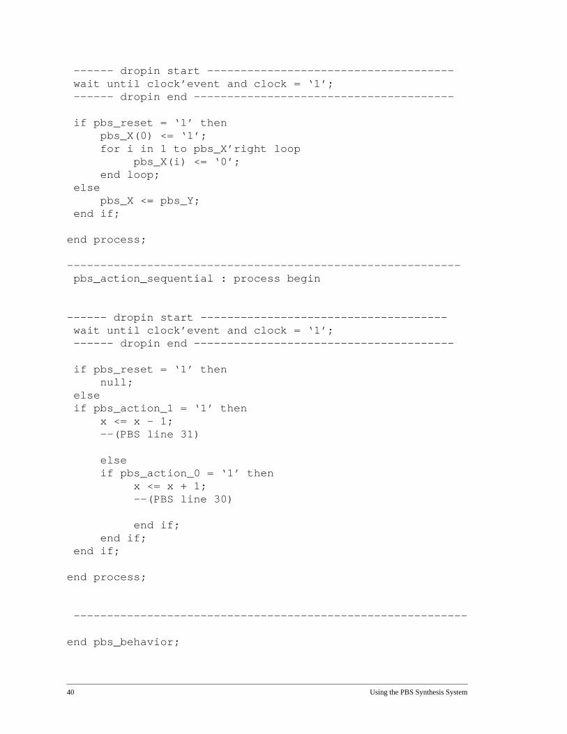
Appendix B: VHDL Output Example
-- File Generated Wed Aug 31 13:12:16 1994-- PBS Version v2.1 - Tue Aug 30 16:54:17 PDT 1994---- PBS Generated VHDL entity---- PBS Compiler Copyright (c) 1992,1993-- University of California.----
entity better_mouse isport (------ dropin start -------------------------------------
xc, xd, clock, reset : in bit;xp : out integer range 0 to 255
------ dropin end ---------------------------------------
);end;
architecture pbs_behavior of better_mouse is
signal pbs_X, pbs_Y : bit_vector (0 to 7);signal pbs_reset : bit;signal pbs_action_0 : bit;signal pbs_action_1 : bit;
------ dropin start -------------------------------------signal x : integer range 0 to 255;
------ dropin end ---------------------------------------
begin
------ dropin start -------------------------------------xp <= x;pbs_reset <= reset;
------ dropin end ---------------------------------------pbs_main_combo : process (pbs_X, xd, xc

Using the PBS Synthesis System 39
variable t0x53ffc, t0x53f24, t0x542b4, t0x5429c,t0x542e4, t0x146994, t0x14697c, t0x146964,t0x542cc, t0x54014, t0x53f0c, t0x5402c,t0x54044, t0x14694c : bit;
begin
t0x53f24 := not xc; t0x53ffc := xd and t0x53f24; t0x5429c := pbs_X(2) and t0x53ffc; t0x542b4 := (pbs_X(3) and t0x53ffc) or ((not pbs_X(3)) andt0x5429c); t0x53f0c := xc; t0x54014 := xd and t0x53f0c; t0x542cc := pbs_X(2) and t0x54014; t0x542e4 := (pbs_X(3) and t0x54014) or ((not pbs_X(3)) andt0x542cc); t0x5402c := (not xd) and t0x53f24; t0x14694c := pbs_X(5) and t0x5402c; t0x146964 := (pbs_X(6) and t0x5402c) or ((not pbs_X(6)) andt0x14694c);
t0x54044 := (not xd) and t0x53f0c; t0x14697c := pbs_X(5) and t0x54044; t0x146994 := (pbs_X(6) and t0x54044) or ((not pbs_X(6)) andt0x14697c);
pbs_Y(0) <= ‘0’; pbs_Y(1) <= ‘1’; pbs_Y(2) <= t0x53ffc; pbs_Y(3) <= t0x542b4; pbs_Y(4) <= t0x542e4; pbs_Y(5) <= t0x5402c; pbs_Y(6) <= t0x146964; pbs_Y(7) <= t0x146994; pbs_action_0 <= t0x542e4; pbs_action_1 <= t0x146994;
end process;
-----------------------------------------------------------
pbs_main_sequential : process begin
40 Using the PBS Synthesis System
------ dropin start ------------------------------------- wait until clock’event and clock = ‘1’; ------ dropin end ---------------------------------------
if pbs_reset = ‘1’ thenpbs_X(0) <= ‘1’;for i in 1 to pbs_X’right loop
pbs_X(i) <= ‘0’;end loop;
elsepbs_X <= pbs_Y;
end if;
end process;
----------------------------------------------------------- pbs_action_sequential : process begin
------ dropin start ------------------------------------- wait until clock’event and clock = ‘1’; ------ dropin end ---------------------------------------
if pbs_reset = ‘1’ thennull;
else if pbs_action_1 = ‘1’ then
x <= x - 1;--(PBS line 31)
elseif pbs_action_0 = ‘1’ then
x <= x + 1;--(PBS line 30)
end if;end if;
end if;
end process;
-----------------------------------------------------------
end pbs_behavior;

41
Symbols! sequential not operator 14!! exception operator 15!E excitation operator 16!R reset operator 15& Boolean AND 16&& sequential AND operator 13* Kleene Closure operator 13+ one or more operator 14, concatenation operator 11. always TRUE token 22: 16: qualification operator 16@ empty token 22^ Boolean XOR 16^ multiple concatenation operator 12| Boolean OR 16|| sequential OR operator 12~ Boolean NOT 16
Aaction clauses 19
acceptable placement 20action_decl 25actions 8, 18, 19
declarations 25defaults 25execution 21precedence 21, 22
architecturedeclarations 25
architecture_decl 25architecture_end 25architecture_front 25ATT netlist 29, 31
Bbehavior
PBS design entitiy 20time sequence 9
bit_type 26BLIF 29, 31Boolean AND 16Boolean EXCLUSIVE-OR 16Boolean NOT 16Boolean OR 16
CC code 32clock 24combo_defaults 25command line syntax 29comments
PBS 23VHDL 23
concatenation operator 11
Ddeclaration 6design interface 6, 24drop-ins 24, 32
Eenvironment and support section 24
exception operator 15exception operators 15excitation operator 16
Ffiles
input 28output
ATT netlist 29, 31
BLIF 29, 31
C code 29, 32
data 28
target language 32
VHDL 28, 30
Ggarbage collection 29
Hhandler 15hooking 26
Iinput signals 6Inspect Mode 32
commands 32interface
VHDL 24interface signal declaration section 27
KKleene Closure operator 13
Llogic synthesis 28
MMarker 17marker 6, 10, 17Mealy machine 26Moore machine 26mouse 8multiple concatenation operator 12
Oone or more operator 14operator
precedence 18Operator Precedence 18operators
Boolean 16composition 7, 11
combinational 7
sequential 7Regular Expression 10
Ppackages
VHDL 24PBS compiler 27

42
PBS declarations 6pbs_reset 26port declaration 24processes
combinational 19sequential 19
production definition section 27productions 6, 7, 10
advanced 21Boolean 7example 8, 10, 13primitive 21recursive 9referencing 9, 10sequential 7symbols 9syntax 9top-level 8
Qqualification operator 16
Rreachable state analysis 29
partitioning 30partitions 29time complexity 30
recovery 15reset conditions 26reset operator 15resource sharing 29resources
conflicts 30sharing 30
re-synchronization mechanism 15
Ssequence factoring 12sequential and operator 13sequential NOT operator 14sequential OR operator 12signal type
VHDL 26simulation
PBS 32VHDL 33
specificationapplicative 6declarative 6
symbols 9special 22terminal 22
synthesis 33
Ttokens 7
recognition 8
VVHDL 6, 29, 30
combinational process 19sequential process 19