PBCC40 CUTTING TOOL - stanleyinfrastructure.com
16
© 2017 STANLEY Black & Decker, Inc. New Britain, CT 06053 U.S.A. 81142 11/2019 Ver. 4 USER MANUAL Safety, Operation and Maintenance PBCC40 CUTTING TOOL
Transcript of PBCC40 CUTTING TOOL - stanleyinfrastructure.com

© 2017 STANLEY Black & Decker, Inc.New Britain, CT 06053
U.S.A.81142 11/2019 Ver. 4
USER MANUAL Safety, Operation and Maintenance
PBCC40CUTTING TOOL


PBCC40 User Manual ◄ 3
TABLE OF CONTENTS
SAFETY SYMBOLS ..............................................................................................................................................4SAFETY PRECAUTIONS ....................................................................................................................................5TOOL ANATOMY ..................................................................................................................................................6SPECIFICATIONS & ACCESSORIES ................................................................................................................7OPERATION .........................................................................................................................................................8REPLACING THE BLADES .................................................................................................................................9TROUBLESHOOTING .........................................................................................................................................10PBCC40 PARTS ILLUSTRATION ........................................................................................................................11PBCC40 PARTS LIST ...........................................................................................................................................12PBCC40 HYDRAULIC BODY ILLUSTRATION ..................................................................................................13PBCC40 RESERVOIR PARTS LIST ...................................................................................................................14PBCC40 CUTTING HEAD ....................................................................................................................................15
SERVICING: This manual contains safety, operation and routine maintenance instructions. STANLEY Infrastructure recommends that servicing of hydraulic tools, other than routine maintenance, must be performed by an authorized and certified dealer. Please read the following warning.
To fill out a product warranty validation form, and for information on your warranty, visit www.stanleyinfrastructure.com and select the Company tab > Warranty.
Note: The warranty validation record must be submitted to validate the warranty.
SERIOUS INJURY OR DEATH COULD RESULT FROM THE IMPROPER REPAIR OR SERVICE OF THIS TOOL.
REPAIRS AND / OR SERVICE TO THIS TOOL MUST ONLY BE DONE BY AN AUTHORIZED AND CERTIFIED DEALER.
For the nearest certified dealer, call STANLEY Infrastructure at (503) 659-5660 and ask for a Customer Service Representative.

4 ► PBCC40 User Manual
Always observe safety symbols. They are included for your safety and for the protection of the tool.
LOCAL SAFETY REGULATIONSEnter any local safety regulations here. Keep these instructions in an area accessible to the operator and maintenance personnel.
Safety symbols and signal words, as shown below, are used to emphasize all operator, maintenance and repair actions which, if not strictly followed, could result in a life-threatening situation, bodily injury or damage to equipment.
This is the safety alert symbol. It is used to alert you to potential personal injury hazards. Obey all safety messages that follow this symbol to avoid possible injury or death.
This safety alert and signal word indicates an imminently hazardous situation which, if not avoided, will result in death or serious injury.
This safety alert and signal word indicates a potentially hazardous situation which, if not avoided, could result in death or serious injury.
This safety alert and signal word indicates a potentially hazardous situation which, if not avoided, could result in death or serious injury.
This signal word indicates a potentially hazardous situation which, if not avoided, may result in property damage.
This signal word indicates a situation which, if not avoided, will result in damage to the equipment.
This signal word indicates a situation which, if not avoided, may result in damage to the equipment.
SAFETY SYMBOLS
PBCC40 User Manual ◄ 5
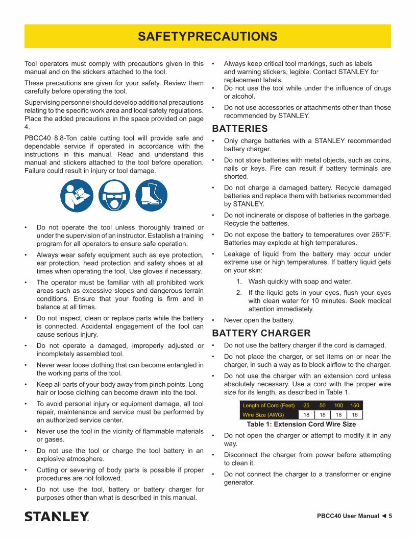
Tool operators must comply with precautions given in this manual and on the stickers attached to the tool.These precautions are given for your safety. Review them carefully before operating the tool.Supervising personnel should develop additional precautions relating to the specific work area and local safety regulations. Place the added precautions in the space provided on page 4.PBCC40 8.8-Ton cable cutting tool will provide safe and dependable service if operated in accordance with the instructions in this manual. Read and understand this manual and stickers attached to the tool before operation. Failure could result in injury or tool damage.
• Do not operate the tool unless thoroughly trained or under the supervision of an instructor. Establish a training program for all operators to ensure safe operation.
• Always wear safety equipment such as eye protection, ear protection, head protection and safety shoes at all times when operating the tool. Use gloves if necessary.
• The operator must be familiar with all prohibited work areas such as excessive slopes and dangerous terrain conditions. Ensure that your footing is firm and in balance at all times.
• Do not inspect, clean or replace parts while the battery is connected. Accidental engagement of the tool can cause serious injury.
• Do not operate a damaged, improperly adjusted or incompletely assembled tool.
• Never wear loose clothing that can become entangled in the working parts of the tool.
• Keep all parts of your body away from pinch points. Long hair or loose clothing can become drawn into the tool.
• To avoid personal injury or equipment damage, all tool repair, maintenance and service must be performed by an authorized service center.
• Never use the tool in the vicinity of flammable materials or gases.
• Do not use the tool or charge the tool battery in an explosive atmosphere.
• Cutting or severing of body parts is possible if proper procedures are not followed.
• Do not use the tool, battery or battery charger for purposes other than what is described in this manual.
• Always keep critical tool markings, such as labels and warning stickers, legible. Contact STANLEY for replacement labels.
• Do not use the tool while under the influence of drugs or alcohol.
• Do not use accessories or attachments other than those recommended by STANLEY.
BATTERIES• Only charge batteries with a STANLEY recommended
battery charger.• Do not store batteries with metal objects, such as coins,
nails or keys. Fire can result if battery terminals are shorted.
• Do not charge a damaged battery. Recycle damaged batteries and replace them with batteries recommended by STANLEY.
• Do not incinerate or dispose of batteries in the garbage. Recycle the batteries.
• Do not expose the battery to temperatures over 265°F. Batteries may explode at high temperatures.
• Leakage of liquid from the battery may occur under extreme use or high temperatures. If battery liquid gets on your skin:
1. Wash quickly with soap and water.2. If the liquid gets in your eyes, flush your eyes
with clean water for 10 minutes. Seek medical attention immediately.
• Never open the battery.
BATTERY CHARGER• Do not use the battery charger if the cord is damaged.• Do not place the charger, or set items on or near the
charger, in such a way as to block airflow to the charger.• Do not use the charger with an extension cord unless
absolutely necessary. Use a cord with the proper wire size for its length, as described in Table 1.
Length of Cord (Feet) 25 50 100 150
Wire Size (AWG) 18 18 18 16
Table 1: Extension Cord Wire Size• Do not open the charger or attempt to modify it in any
way.• Disconnect the charger from power before attempting
to clean it.• Do not connect the charger to a transformer or engine
generator.
SAFETY PRECAUTIONS

6 ► PBCC40 User Manual
TOOL ANATOMY
DO NOT put fingers, hands or other body parts between the cutting head. Serious injury will result!
WHAT IS THE PBCC40 CUTTING TOOL?The PBCC40 is a battery powered 8.8-ton cable cutting tool with a 1.57 inch guillotine style head. The PBCC40 is capable of cutting aluminum rod up to 1.5 inches in diameter, copper rod up to 1 inch in diameter and steel rod up to 3/4 inch in diameter.
Cutting Head
InteLED
Trigger Lock
Battery
Trigger
Pressure Release
Cutting Hazard Decal
Tool Identification & Warning Decal

PBCC40 User Manual ◄ 7
SPECIFICATIONSCutting Force ..................................................................................................................................8.8 Tons (86.3 kN)Cutting Capacity .................................................................................................. Copper & Aluminum to 2000 MCM
ACSR to 1590Steel Cable to .75”
Aluminum Rod to 1.5”Copper Rod to 1”Steel Rod to .75”
Jaw Type ............................................................................................................................................ 1.57” Guillotine
Estimated Cuts per Battery Charge .........................................................................................................................80Tool Cycle Time .......................................................................................................................................6.5 Seconds
Battery Type ..............................................................................................................DEWALT 20V Max, 5 amp/hour
Tool Weight ................................................................................................................................................... 16.7 Lbs.Tool Length ............................................................................................................................................... 18.5 Inches
Maintenance Interval ............................................................................................................................ 15,000 Cycles
ACCESSORIES5 Amp/hour Lithium Ion Battery ........................................................................................................................DC2055 Amp/hour Lithium Ion Battery 2-pack ...................................................................................................... DCB205-2
120V AC Charger ...........................................................................................................................................DCB11512V DC Charger .............................................................................................................................................DCB119Note: Only use battery chargers recommended by STANLEY.Bucket Bag ......................................................................................................................................................... BB01
SPECIFICATIONS & ACCESSORIES
8 ► PBCC40 User Manual
OPERATION
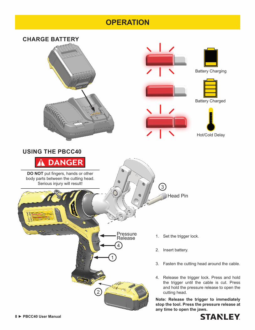
CHARGE BATTERY
Battery Charging
Battery Charged
Hot/Cold Delay
USING THE PBCC40
1. Set the trigger lock.
2. Insert battery.
3. Fasten the cutting head around the cable.
4. Release the trigger lock. Press and hold the trigger until the cable is cut. Press and hold the pressure release to open the cutting head.
Note: Release the trigger to immediately stop the tool. Press the pressure release at any time to open the jaws.
1
2
3
4
Head Pin
Pressure Release
DO NOT put fingers, hands or other body parts between the cutting head.
Serious injury will result!

PBCC40 User Manual ◄ 9
OPERATION
INTELED SYSTEMThe InteLED light ring shows the status of the cut in real-time.White - The tool is cutting. InteLED will stay lit for 30 seconds after the cut is complete.Green - The tool has developed full hydraulic pressure during the cut.Red - The tool did not develop full pressure during the cut. You may need to cycle the tool again.
CHECKING BATTERY CHARGE
75 - 100% Charged
51 - 74% Charged
Less than 50% Charged
Charge Battery
Battery Charge Button
REPLACING THE BLADES
DO NOT install or change blades while the battery is connected to the tool. Disconnect the battery BEFORE
installing or changing blades.

10 ► PBCC40 User Manual
Problem SolutionThe head pin won’t fit through the hole in the cutting head.
Press and hold the pressure release. Ensure the two halves of the cutting head are aligned. Close the cutting head and insert the head pin.
The tool won’t cut when I press the trigger. Ensure the battery is charged. Disengage the trigger lock.
The InteLED flashes yellow when I activate the tool. The maintenance interval is about to elapse. Have the tool serviced as soon as possible.
The tool repeatedly give me bad cuts / The InteLED flashes red after every crimp.
Ensure the battery is fully charged. Ensure the blades are in good condition. If problem persists, have the tool serviced as soon as possible.
The tool is leaking hydraulic oil. Have the tool serviced immediately.
TROUBLESHOOTING

PBCC40 User Manual ◄ 11
PBCC40 PARTS ILLUSTRATION
264
93
41
270
272
43
120
136
265
87
46
155
156
263
48
444742
50
49
135
31
99
115
16194
89
98
250
252
25125
3
37
38
37
102
105
104
101
105
43
103
106
12 ► PBCC40 User Manual
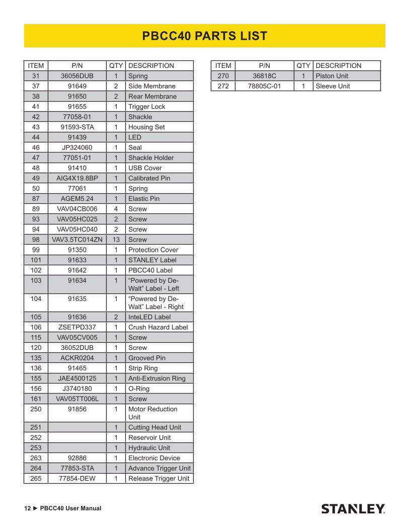
PBCC40 PARTS LIST
ITEM P/N QTY DESCRIPTION31 36056DUB 1 Spring37 91649 2 Side Membrane38 91650 2 Rear Membrane41 91655 1 Trigger Lock42 77058-01 1 Shackle43 91593-STA 1 Housing Set44 91439 1 LED46 JP324060 1 Seal47 77051-01 1 Shackle Holder48 91410 1 USB Cover49 AIG4X19.8BP 1 Calibrated Pin50 77061 1 Spring87 AGEM5.24 1 Elastic Pin89 VAV04CB006 4 Screw93 VAV05HC025 2 Screw94 VAV05HC040 2 Screw98 VAV3.5TC014ZN 13 Screw99 91350 1 Protection Cover101 91633 1 STANLEY Label102 91642 1 PBCC40 Label103 91634 1 “Powered by De-
Walt” Label - Left104 91635 1 “Powered by De-
Walt” Label - Right105 91636 2 InteLED Label106 ZSETPD337 1 Crush Hazard Label115 VAV05CV005 1 Screw120 36052DUB 1 Screw135 ACKR0204 1 Grooved Pin136 91465 1 Strip Ring155 JAE4500125 1 Anti-Extrusion Ring156 J3740180 1 O-Ring161 VAV05TT006L 1 Screw250 91856 1 Motor Reduction
Unit251 1 Cutting Head Unit252 1 Reservoir Unit253 1 Hydraulic Unit263 92886 1 Electronic Device264 77853-STA 1 Advance Trigger Unit265 77854-DEW 1 Release Trigger Unit
ITEM P/N QTY DESCRIPTION270 36818C 1 Piston Unit272 78805C-01 1 Sleeve Unit

PBCC40 User Manual ◄ 13
76
21
258256
256
259
267
119
118257
77
73
12
125
9571
4
11
95
96
63
69
28
82
83
65
258
PBCC40 HYDRAULIC BODY ILLUSTRATION
ITEM P/N QTY DESCRIPTION4 77504 1 Spring11 BILL06.35 1 Ball12 30189DUB 1 Spring21 91571 1 Hydraulic Body28 77026-04 1 Spring63 87213 1 Spring65 AAIN30 1 Circlip69 J0720190 1 O-Ring71 BILL04.76 1 Ball73 J0290178PU70 1 O-Ring76 J4300200 1 O-Ring77 JAE0500100 1 Anti-extrusion Ring82 JSR1927205 1 Wiper Ring83 R1B12.30.08Z 1 Ball Bearing
ITEM P/N QTY DESCRIPTION95 VIV08TT008 2 Screw96 VAV06TT008 1 Screw118 77030 1 Spring119 77016 1 Sliding Part125 BILL03.175 1 Ball256 77803 1 Release Device257 77805-01 2 Delivery Valve Unit258 77806-01 1 Succion Valve Unit259 77848C-02 1 Spring Collar Unit260 77849C 1 Cam Compartment
Unit267 77804C 1 Commutator
14 ► PBCC40 User Manual
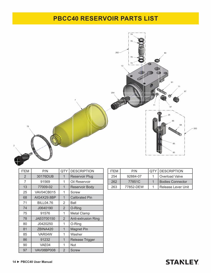
PBCC40 RESERVOIR PARTS LIST
ITEM P/N QTY DESCRIPTION2 30176DUB 1 Reservoir Plug7 91569 1 Oil Reservoir13 77009-02 1 Reservoir Body25 VAV04CB015 1 Screw68 AIG4X29.8BP 1 Calibrated Pin71 BILL04.76 2 Ball74 J0640190 2 O-Ring75 91576 1 Metal Clamp78 JAE0700150 2 Anti-extrusion Ring80 J0420250 1 O-Ring81 ZBINA420 1 Magnet Pin85 VAR04W 1 Washer86 91232 1 Release Trigger90 VAE04 1 Nut97 VAV08BP008 2 Screw
71
90
85
68
86
25
97
97
71
81
80
74
78
78
7413
7
75
2
263
262
254
ITEM P/N QTY DESCRIPTION254 92884-07 1 Overload Valve262 77851C 1 Bodies Connector263 77852-DEW 1 Release Lever Unit

PBCC40 User Manual ◄ 15
PBCC40 CUTTING HEAD
82
85
83
75
76
78
77
79
81
80
56
6285
81
55
ITEM P/N QTY DESCRIPTION55 77495 1 Double Fork Head56 36058DUB 1 Locking Pin62 VAV04PF 1 Ball Headed Dowel75 36051DUB 1 Counter Blade Base76 36052DUB 1 Blade77 36054DUB 1 Slide Way78 36055DUB 1 Slide Way79 36057DUB 1 Pin80 36059DUB 2 Pin81 AAEN12 2 Circlip82 TCA01.5 .13 Stainless Steel Cable
ITEM P/N QTY DESCRIPTION83 VAV10HC030 4 Screw85 VAV05TT010 2 Screw

STANLEY Infrastructure6430 SE Lake Road
Portland, Oregon 97222 USA(503) 659-5660 / Fax (503) 652-1780
www.stanleyinfrastructure.com