
Pb–Ag Alloy Anode Modified with Polyaniline Film and its ...6724 2.2 Cleaning of the working...
15
Int. J. Electrochem. Sci., 14 (2019) 6722 – 6736, doi: 10.20964/2019.07.46 International Journal of ELECTROCHEMICAL SCIENCE www.electrochemsci.org Pb–Ag Alloy Anode Modified with Polyaniline Film and its Electrochemical Performance in Sulfuric Acid Electrolyte PeiPei Li 1 , RenChun Fu *,1 , Du Jun 2 , Hui Huang 2,3 , ZhongCheng Guo 2,3 1 Department of science, Kunming University of Science and Technology, Kunming 650093, China; 2 Department of Metallurgy and Energy Engineering, Kunming University of Science and Technology, Kunming 650093, China; 3 Kun Ming Hendera of Science and Technology Co.,Ltd.,Kunming 650106, China. * E-mail: [email protected] Received: 28 January 2019 / Accepted: 29 March 2019 / Published: 10 June 2019 The nature of the electrode surface plays an important role in the electrode reaction. In this study, Pb– Ag alloy anodes modified with polyaniline films were prepared by galvanostatic polymerisation. Linear scanning voltammetry (LSV), cyclic voltammetry and potentiodynamic polarisation were measured and compared with those of unprepared Pb–Ag (0.3 wt%) alloy anodes. The oxygen evolution reaction potential of the modified anodes was lower than that of the unprepared Pb–Ag (0.3 wt%) anode at same anodic current density. The corrosion resistance of the modified anode was better than that of the unprepared Pb–Ag (0.3 wt%) anode. SEM images were obtained to characterise the morphology of the polyaniline film, and FTIR spectra confirmed that the film coating the Pb–Ag alloy was polyaniline. Keywords: polyaniline; cyclic voltammetry; linear scanning voltammetry; Pb–Ag alloy 1. INTRODUCTION Pb–Ag (0.3–1 wt%) alloy is widely used as anode material for electrowinning of nonferrous metals, such as Cu, Zn, Ni, Co and Mn, because of its excellent corrosion resistance in acidic sulfate solution. However, Pb–Ag alloy anodes have high over potential of the oxygen evolution reaction (OER) and cause contamination of the Pb ion in the cathodic products. In the last decade, various methods have been developed to reduce the over potential of OER and prevent the dissolution of the Pb–Ag anodes. For example, Ca, Sn, Sr, Co, Sb, In, and Mn ions were dispersed in Pb–Ag alloys to make binary and ternary alloys [1–3]; noble metal oxides (RuO2, IrO2 and ZrO2) [4,5] and base metal oxides (MnO2, PbO2, TiO2, Co3O4 and SnO2) [6–8] were used to coat Pb–Ag alloys to make dimensionally stable anode (DSA). Conductive polymer represents another approach to reduce the energy consumption of electrowinning and achieve pure cathodic products [9].
Transcript of Pb–Ag Alloy Anode Modified with Polyaniline Film and its ...6724 2.2 Cleaning of the working...

Int. J. Electrochem. Sci., 14 (2019) 6722 – 6736, doi: 10.20964/2019.07.46
International Journal of
ELECTROCHEMICAL SCIENCE
www.electrochemsci.org
Pb–Ag Alloy Anode Modified with Polyaniline Film and its
Electrochemical Performance in Sulfuric Acid Electrolyte
PeiPei Li1, RenChun Fu*,1, Du Jun2, Hui Huang2,3, ZhongCheng Guo 2,3
1 Department of science, Kunming University of Science and Technology, Kunming 650093, China; 2 Department of Metallurgy and Energy Engineering, Kunming University of Science and Technology,
Kunming 650093, China; 3 Kun Ming Hendera of Science and Technology Co.,Ltd.,Kunming 650106, China. *E-mail: [email protected]
Received: 28 January 2019 / Accepted: 29 March 2019 / Published: 10 June 2019
The nature of the electrode surface plays an important role in the electrode reaction. In this study, Pb–
Ag alloy anodes modified with polyaniline films were prepared by galvanostatic polymerisation. Linear
scanning voltammetry (LSV), cyclic voltammetry and potentiodynamic polarisation were measured and
compared with those of unprepared Pb–Ag (0.3 wt%) alloy anodes. The oxygen evolution reaction
potential of the modified anodes was lower than that of the unprepared Pb–Ag (0.3 wt%) anode at same
anodic current density. The corrosion resistance of the modified anode was better than that of the
unprepared Pb–Ag (0.3 wt%) anode. SEM images were obtained to characterise the morphology of the
polyaniline film, and FTIR spectra confirmed that the film coating the Pb–Ag alloy was polyaniline.
Keywords: polyaniline; cyclic voltammetry; linear scanning voltammetry; Pb–Ag alloy
1. INTRODUCTION
Pb–Ag (0.3–1 wt%) alloy is widely used as anode material for electrowinning of nonferrous
metals, such as Cu, Zn, Ni, Co and Mn, because of its excellent corrosion resistance in acidic sulfate
solution. However, Pb–Ag alloy anodes have high over potential of the oxygen evolution reaction (OER)
and cause contamination of the Pb ion in the cathodic products. In the last decade, various methods have
been developed to reduce the over potential of OER and prevent the dissolution of the Pb–Ag anodes.
For example, Ca, Sn, Sr, Co, Sb, In, and Mn ions were dispersed in Pb–Ag alloys to make binary and
ternary alloys [1–3]; noble metal oxides (RuO2, IrO2 and ZrO2) [4,5] and base metal oxides (MnO2,
PbO2, TiO2, Co3O4 and SnO2) [6–8] were used to coat Pb–Ag alloys to make dimensionally stable anode
(DSA). Conductive polymer represents another approach to reduce the energy consumption of
electrowinning and achieve pure cathodic products [9].

Int. J. Electrochem. Sci., Vol. 14, 2019
6723
As one of the most frequently investigated conductive polymers, polyaniline (PANI) has been
widely investigated, particularly its synthesis, structure and fundamental properties, such as
conductivity, optical nonlinearity and mechanical performance [10–12]. Previous works indicated that
conductive PANI is promising for many future practical applications. For example, conductive PANI
was used as an electrode component to improve the electrocatalytic performance of the anode [13–15];
PANI and its composites were also used for protection of substrate metals [16, 17]. Researchers
extensively studied the electrochemical syntheses of conductive PANI coatings on oxidisable metals for
protection purposes. For example, the stability of the PANI film was improved [18], the protection
mechanism was investigated [19, 20], and the electrocatalytic properties were improved [21]. Aniline
electropolymerisation proceeds according to the following Figure 1 [22, 23]:
N
H
.N
H
H
.+
H
N
H
H
+N
H
H
+-2H +
N
H
H
N
-e-
H+
N H 2
aniline
H
-2e-
-2H +polym er
Figure 1. Mechanism of aniline electropolymerisation
Liao [24] demonstrated that Figure 1 was the mechanism of not only electro synthesised PANI
film but also autocatalytic polymerized PANI film. The polymerisation process of electropolymerised
PANI film on the metal substrate surface includes three stages [25].
For the electrowinning of nonferrous metals, the anode should reduce the OER potential and
improve corrosion resistance. Therefore, this paper aims to prepare a PANI film on the surface of a Pb–
Ag alloy anode and investigate the potential of OER and corrosion resistance of the modified anode.
PANI films were prepared by galvanostatic polymerisation at different current densities.
Potentiodynamic polarisation curves, scanning electron microscopy (SEM) images, cyclic
voltammograms, X-ray photoelectron spectroscopy (XPS) spectra and LSV were employed to character
the properties of the new anode.
2. EXPERIMENTS AND DETAILS
2.1 Chemicals and equipment
The chemicals used in this experiment were of analytical grade. Sulfuric acid (H2SO4) and aniline
were purchased from Aladdin Chemistry Co., Ltd. The aniline was distilled under reduced pressure prior
to use. Pb–Ag (0.3 wt%) alloys were purchased from Kunming Hendera Science and Technology Co.,
Ltd., China. Deionised water was used in all experiments. The electrochemical workstation was model
CHI1760 made by Shanghai Chen Hua Co., Ltd.
Int. J. Electrochem. Sci., Vol. 14, 2019
6724
2.2 Cleaning of the working electrode
Pb–Ag (0.3 wt%) alloy was cut into a 1cm×1cm×0.2cm slide and polished by 400#, 800#, 1000#,
and 1200# sand paper to obtain a mirror-bright surface and reduce the influence of the surface roughness.
One side and four edges of the slide were cast with denture base resin (type II,Dental Materials Factory
of Shanghai Medical Instruments Co. Ltd., China) with a working area of 1.0cm2.The working electrode
was used immediately after it was sequentially rinsed with deionized water and acetone and dried at
50°C.
2.3 Electro polymerisation
The PANI film was electropolymerised in an aqueous solution containing aniline (0.2 mol L−1)
and H2SO4 (0.5 mol L−1). The PANI moded anode was obtained by galvanostatic polymerisation at
current densities of 0.5, 1.5, 2.5, 3.5 and 4.5 mA cm−2 and time of 1200s. Thus, five different PANI-
modified anode samples were prepared. Galvanostatic polymerisation was carried out at 0.5 mA cm−2
on Pb–Ag (0.3wt%) alloy named PFPbAg-0.5. The 1.5mA cm−2 sample was named PFPbAg-1.5. The
2.5mA cm−2 sample was named PFPbAg-2.5. The 3.5mA cm−2 sample was named PFPbAg-3.5. The
4.5mA cm−2 sample was named PFPbAg-4.5.
2.4 Characterisation tests
Characterization tests were carried out after the PANI film on the Pb–Ag (0.3 wt%) alloy was
rinsed with deionized water to remove any residual electrolyte and oligomers.
The electrochemical experiments (linear scanning voltammetry, cyclic voltammetry and
potentiodynamic polarisation) were carried out in a three-electrode system. A saturated calomel
electrode (SCE) was used as the reference electrode, and a platinum plate (2.5 cm2) was used as the
counter electrode. The working electrodes were the unprepared Pb–Ag (0.3 wt%) alloy or PANI-
modified anodes with geometric area of 1 cm2 and thickness of 2 mm. During electrochemical
experiments, the solution was not stirred, not deaerated or aerated, but simply exposed to air at room
temperature.
The linear scanning voltammetry measurements were done at a scanning rate of 1 mV/s in 0.5
mol L−1 H2SO4 aqueous solution.
The scan rate of cyclic voltammetry was 10 mV/s in 0.5 mol L−1 H2SO4 and 0.2 mol L−1 aniline.
At a constant scan rate of 1mV·s−1, potentiodynamic polarisation curves for the PANI-modified
anodes and unprepared Pb–Ag alloys were obtained in 0.5 mol L−1 H2SO4 electrolyte.
The morphology of the PANI samples was investigated by SEM. The PANI powder was scraped
from the substrate, dispersed in potassium bromide, and then compressed into pellets to measure its FTIR
spectrum. FTIR spectra were obtained in the KBr phase with a Perkin Elmer (RK-1310) FTIR
spectrometer. The surface composition of the PANI-modified anode was determined by XPS (PHI5500,
Perkin–Elmer) using Mg Kα X-rays (1253.6 eV) under a pressure of below 5×10⁻⁸ Pa.

Int. J. Electrochem. Sci., Vol. 14, 2019
6725
3. RESULTS AND DISCUSSION
3.1 Growth processes of PANI film on the Pb–Ag (0.3 wt%) alloy
The formation of a PANI film on the Pb–Ag (0.3 wt%) alloy in aqueous H2SO4 solution involves
two steps. In the first step, the surface Pb was oxidised [26] and the first nuclei of polyaniline were
formed at the same time. The XPS spectra (Figure 11) indicate the lead oxide film is PbO and PbSO4
film. The PANI film was formed on the PbO film or PbSO4 film in the second step. Figure 2 shows that
the potential of the anode changed during the first 500 s. When the current density was constant at 1.5,
2.5 and 4.5 mA cm−2, the anode potential increased to about 1.7 V and remained steady for about 140 s,
then decreased to the final steady potential of about 1.35 V. These changes in the anode potential reflect
the PANI growth process. Initially, a defined current density was forced to flow, but electro
polymerisation (oxidation) was not sufficient to produce that current. Thus, the potential was shifted to
higher values, and formation of PbO2 may occur. When the potential increased to 1.7 V, above the
potential of aniline polymerisation, the PANI granules grew on the Pb–Ag (0.3 wt%) alloy surface. After
about 180 s, PANI film covered the alloy surface. The PANI underwent an autocatalytic reaction
(mechanism of autocatalytic reaction shown in Figure 1), so the electro polymerisation rate increased.
This reaction became sufficiently fast to produce the required current flow, so the potential decreased.
Finally, the steady potential (about 1.35 V) was the potential needed to maintain the electro
polymerisation reaction at the rate needed to produce the imposed current density.
When the galvanostatic polymerisation current density was 0.5mA cm−2, the anode potential
increased more slowly to about 1.7 V and then decreased more slowly to the steady polymerisation
potential of about 1.35 V compared with the potential obtained at the other current densities. Thus, the
time needed for the PANI to cover the surface of the sample was longer for PFPbAg-0.5 than for the
other current densities.
After 600 s, the potential was stable for all the different polymerisation current densities. Figure
2 shows that a decrease in current density leads to a falling steady potential because it is partially caused
by anodic polarisation. The lower the current density is, the lower the polarisation potential is.
Figure 2. Anode E–t traces for galvanostatic polymerisation of PANI film on Pb–Ag (0.3 wt%) alloy
in an aqueous solution containing aniline (0.2 mol L−1) and H2SO4 (0.5 mol L−1) at room
temperature
Int. J. Electrochem. Sci., Vol. 14, 2019
6726
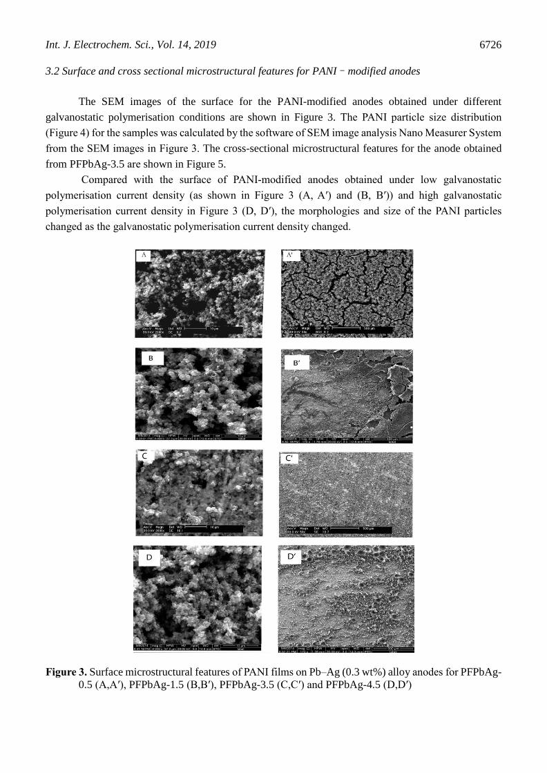
3.2 Surface and cross sectional microstructural features for PANI–modified anodes
The SEM images of the surface for the PANI-modified anodes obtained under different
galvanostatic polymerisation conditions are shown in Figure 3. The PANI particle size distribution
(Figure 4) for the samples was calculated by the software of SEM image analysis Nano Measurer System
from the SEM images in Figure 3. The cross-sectional microstructural features for the anode obtained
from PFPbAg-3.5 are shown in Figure 5.
Compared with the surface of PANI-modified anodes obtained under low galvanostatic
polymerisation current density (as shown in Figure 3 (A, A′) and (B, B′)) and high galvanostatic
polymerisation current density in Figure 3 (D, D′), the morphologies and size of the PANI particles
changed as the galvanostatic polymerisation current density changed.
Figure 3. Surface microstructural features of PANI films on Pb–Ag (0.3 wt%) alloy anodes for PFPbAg-
0.5 (A,A′), PFPbAg-1.5 (B,B′), PFPbAg-3.5 (C,C′) and PFPbAg-4.5 (D,D′)

Int. J. Electrochem. Sci., Vol. 14, 2019
6727
Figure 4. Distributions for PANI particle size of the samples (PFPbAg-0.5,PFPbAg-1.5,PFPbAg-3.5
and PFPbAg-4.5)
According to the results of Figure 4, the particle size distribution was centred at 0.5, 0.8, 2 and 1
µm for PFPbAg-0.5, PFPbAg-1.5, PFPbAg-3.5 and PFPbAg-4.5, respectively. Lower galvanostatic
polymerisation current densities (PFPbAg-0.5 and PFPbAg-1.5)) yielded smaller particles. Figure 3
shows cracks in the PANI film for lower current densities, whereas higher current densities (PFPbAg-
4.5) yielded structural porosity, and the surface of the PANI film was rough. When the galvanostatic
polymerisation current density was 3.5mA cm−2, the PANI film was densified.
Figure 5. Cross sectional microstructural features of the anode obtained under galvanostatic
polymerisation current density 3.5 mA cm−2.

Int. J. Electrochem. Sci., Vol. 14, 2019
6728
Figure 5 shows that the thickness of the PANI film was about 140 µm when galvanostatic
polymerisation lasted 1200 s, and the growth of the PANI particles expanded from the nuclei.
The growth of three-dimensional hemispherical nuclei was investigated carefully by Scharifker
[27], who assumed that the reaction was completely diffusion controlled and obtained the following
relationships between the current (I) and the time (t) for nucleation:
For instantaneous nucleation:
1
2
1 1
2 2
1 exp( ) (1)zFD C
I N KDt
t
For progressive nucleation 1
22
1 1
2 2
1 exp( ) / 2 (2)zFD C
I AN KDt
t
In Equations (1) and (2), zF is the molar charge of the electrodeposited species, D is the diffusion
coefficient, c is the bulk concentration, k is a constant, and N is the number of nuclei. The A is nucleation
rate per active site, and the N is the density of active sites.
Equations (1) and (2) show that the value of A and N are important parameters for PANI
nucleation on the metal surface during electrosynthesis. Under the same condition, the number of nuclei
(N) is equivalent to the same nucleation time (t). Within the same interval t , samples with high current
will have more charge quantity Q according to the relation Q I t . Therefore, lower galvanostatic
polymerisation current densities (0.5 and 1.5 mA cm−2) provide minimal charge quantity, the samples
yield smaller particles (Figure 3 (A,A′) and (B,B′)), and the galvanostatic polymerisation current
densities (3.5 mA cm−2) yield larger particles, as shown in Figure 3 (C,C′). When the galvanostatic
polymerisation current density increased to 4.5 mA cm−2, high current density resulting in
polymerisation of aniline grew rapidly. The structure of the PANI film was porous, as shown in Figure
3 (D, D′).
3.3 LSV analysis of different anodes
The electrode reaction of oxygen evolution reaction in anode polarisation is: +
2 22 4 4H O H O e (3)
The equilibrium potential (eE ) of oxygen evolution reaction can be calculated from the Nernst
equation according to the parameter of the test condition, and the over-potential of OER is: eE E .
Therefore, the over potential of the oxygen evolution reaction is determined by OER potential.
Int. J. Electrochem. Sci., Vol. 14, 2019
6729
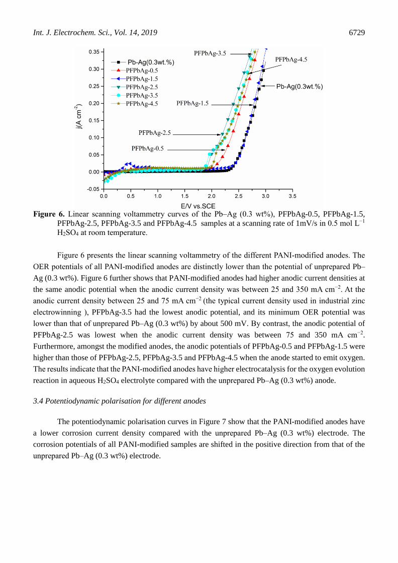
Figure 6. Linear scanning voltammetry curves of the Pb–Ag (0.3 wt%), PFPbAg-0.5, PFPbAg-1.5,
PFPbAg-2.5, PFPbAg-3.5 and PFPbAg-4.5 samples at a scanning rate of 1mV/s in 0.5 mol L−1
H2SO4 at room temperature.
Figure 6 presents the linear scanning voltammetry of the different PANI-modified anodes. The
OER potentials of all PANI-modified anodes are distinctly lower than the potential of unprepared Pb–
Ag (0.3 wt%). Figure 6 further shows that PANI-modified anodes had higher anodic current densities at
the same anodic potential when the anodic current density was between 25 and 350 mA cm−2. At the
anodic current density between 25 and 75 mA cm−2 (the typical current density used in industrial zinc
electrowinning ), PFPbAg-3.5 had the lowest anodic potential, and its minimum OER potential was
lower than that of unprepared Pb–Ag (0.3 wt%) by about 500 mV. By contrast, the anodic potential of
PFPbAg-2.5 was lowest when the anodic current density was between 75 and 350 mA cm−2.
Furthermore, amongst the modified anodes, the anodic potentials of PFPbAg-0.5 and PFPbAg-1.5 were
higher than those of PFPbAg-2.5, PFPbAg-3.5 and PFPbAg-4.5 when the anode started to emit oxygen.
The results indicate that the PANI-modified anodes have higher electrocatalysis for the oxygen evolution
reaction in aqueous H2SO4 electrolyte compared with the unprepared Pb–Ag (0.3 wt%) anode.
3.4 Potentiodynamic polarisation for different anodes
The potentiodynamic polarisation curves in Figure 7 show that the PANI-modified anodes have
a lower corrosion current density compared with the unprepared Pb–Ag (0.3 wt%) electrode. The
corrosion potentials of all PANI-modified samples are shifted in the positive direction from that of the
unprepared Pb–Ag (0.3 wt%) electrode.

Int. J. Electrochem. Sci., Vol. 14, 2019
6730
Figure 7. Potentiodynamic polarisation curves of unprepared Pb–Ag (0.3 wt%), PFPbAg-0.5, PFPbAg-
1.5, PFPbAg-2.5, PFPbAg-3.5 and PFPbAg-4.5 in 0.5 mol L−1 H2SO4 at room temperature
3.5 Cyclic voltammetry for the PANI-modified anodes
To evaluate the redox reaction of the PANI modified anodes, the cyclic voltammograms for two
typical samples (PFPbAg-0.5 and PFPbAg-3.5) are presented in Figure 8 and 9, respectively.
Figure 8. Cyclic voltammograms of PFPbAg-0.5 in 1mol L−1 H2SO4 and 0.2mol L−1 aniline, the scan
rate was 10mVs−1
Int. J. Electrochem. Sci., Vol. 14, 2019
6731
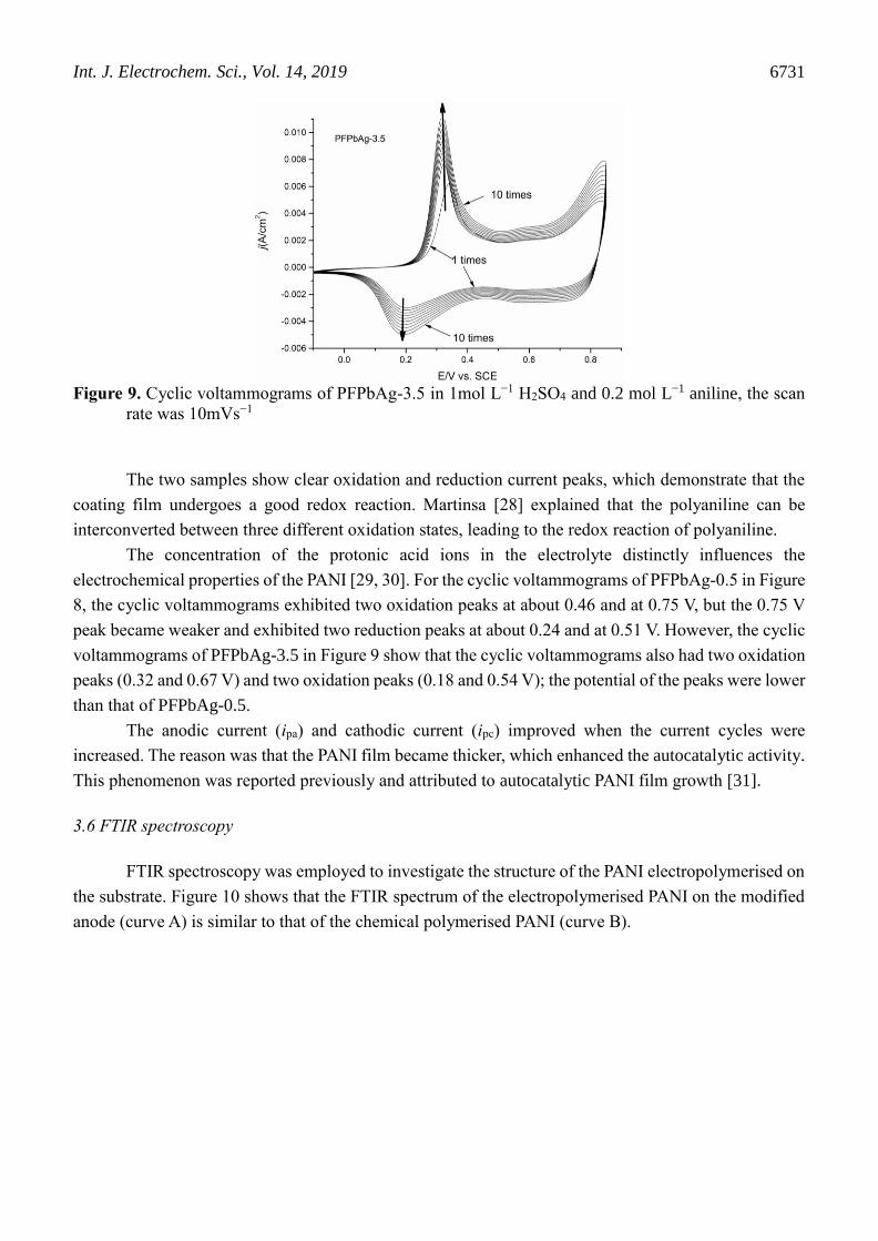
Figure 9. Cyclic voltammograms of PFPbAg-3.5 in 1mol L−1 H2SO4 and 0.2 mol L−1 aniline, the scan
rate was 10mVs−1
The two samples show clear oxidation and reduction current peaks, which demonstrate that the
coating film undergoes a good redox reaction. Martinsa [28] explained that the polyaniline can be
interconverted between three different oxidation states, leading to the redox reaction of polyaniline.
The concentration of the protonic acid ions in the electrolyte distinctly influences the
electrochemical properties of the PANI [29, 30]. For the cyclic voltammograms of PFPbAg-0.5 in Figure
8, the cyclic voltammograms exhibited two oxidation peaks at about 0.46 and at 0.75 V, but the 0.75 V
peak became weaker and exhibited two reduction peaks at about 0.24 and at 0.51 V. However, the cyclic
voltammograms of PFPbAg-3.5 in Figure 9 show that the cyclic voltammograms also had two oxidation
peaks (0.32 and 0.67 V) and two oxidation peaks (0.18 and 0.54 V); the potential of the peaks were lower
than that of PFPbAg-0.5.
The anodic current (ipa) and cathodic current (ipc) improved when the current cycles were
increased. The reason was that the PANI film became thicker, which enhanced the autocatalytic activity.
This phenomenon was reported previously and attributed to autocatalytic PANI film growth [31].
3.6 FTIR spectroscopy
FTIR spectroscopy was employed to investigate the structure of the PANI electropolymerised on
the substrate. Figure 10 shows that the FTIR spectrum of the electropolymerised PANI on the modified
anode (curve A) is similar to that of the chemical polymerised PANI (curve B).
Int. J. Electrochem. Sci., Vol. 14, 2019
6732
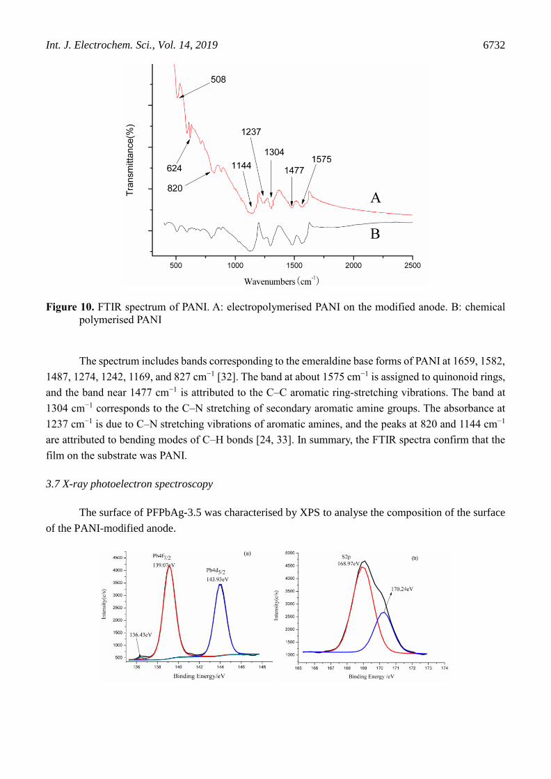
Figure 10. FTIR spectrum of PANI. A: electropolymerised PANI on the modified anode. B: chemical
polymerised PANI
The spectrum includes bands corresponding to the emeraldine base forms of PANI at 1659, 1582,
1487, 1274, 1242, 1169, and 827 cm−1 [32]. The band at about 1575 cm−1 is assigned to quinonoid rings,
and the band near 1477 cm−1 is attributed to the C–C aromatic ring-stretching vibrations. The band at
1304 cm−1 corresponds to the C–N stretching of secondary aromatic amine groups. The absorbance at
1237 cm−1 is due to C–N stretching vibrations of aromatic amines, and the peaks at 820 and 1144 cm−1
are attributed to bending modes of C–H bonds [24, 33]. In summary, the FTIR spectra confirm that the
film on the substrate was PANI.
3.7 X-ray photoelectron spectroscopy
The surface of PFPbAg-3.5 was characterised by XPS to analyse the composition of the surface
of the PANI-modified anode.

Int. J. Electrochem. Sci., Vol. 14, 2019
6733
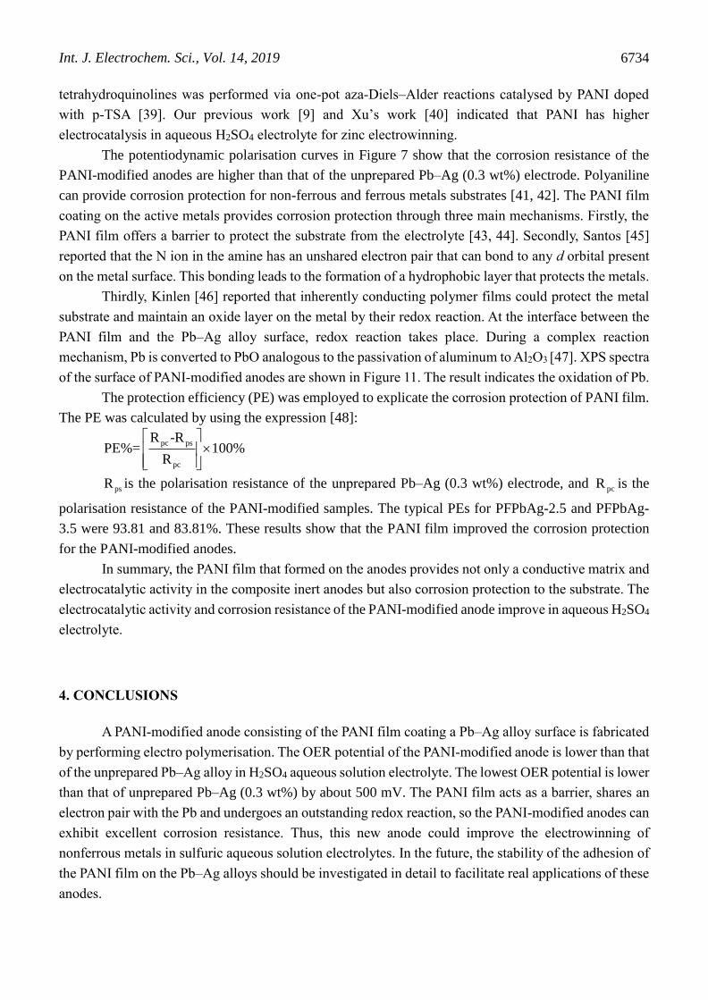
Figure 11. XPS spectra of Pb 4f7/2 and Pb 4f5/2, S2p and O 1s of the surface of the anode obtained
under galvanostatic polymerisation current density 3.5 mA cm−2.
The black line in Figure 11a shows the XPS spectra of Pb. The binding energies 136.43, 139.07
(red line in Figure 11a) and 143.93 eV (blue line in Figure 11a) belong to Pb 4f7/2 and Pb 4f5/2. The
binding energy values close to that of Pb2+ were reported in the literature [34]. The XPS spectra of S2p
shown in Figure 11b (black line) can be fitted well with two components. The peaks observed at 168.97
(red line in Figure 11a) and 170.24 eV (blue line in Figure 11a) correspond to SO42− reported in the
literature [35]. Furthermore, the O1s spectrum shows (Figure 11c) a peak contributed by two components
at 531.94 and 532.49 eV. The binding energies values close to SO42− are also reported in the literature
[35]. In addition, according to Pavlov’s work [36], when Pb electrodes are anodised in H2SO4 solution,
the PbOn (1<n<2), PbS04, tet-PbO and PbO2 species are created on the surface of the anode. Thus, PbSO4
and PbO films are generated on the surface of the Pb–Ag alloy.
3.8 Discussion
The above research results show that the optimal PANI-modified Pb–Ag alloy anode is the one
obtained from galvanostatic polymerisation under the current density of PFPbAg-3.5, and the original
electrolyte solution is aniline (0.2 mol L−1) and H2SO4 (0.5 mol L−1). It possesses higher electrocatalytic
activity and better corrosion resistance in aqueous H2SO4 electrolyte; this is related to the properties of
PANI film on the anode and the electrochemical active site amounts used for oxidation–reduction
transition on the anode surface.
Figure 6 shows that PANI has unique electrocatalysts characteristics in an acidic medium, and
the porous structures of PANI film on the substrate provide a larger activity surface than its geometric
surface (as shown in Figure 3, 4 and 5), which provides a large area for charge exchange and generates
more cation radicals. According to Figure 1, more cation radicals could facilitate the autocatalytic
polymerisation of aniline, thereby improving the electrocatalysis of the PANI-modified anodes. Thus,
PANI was used as an electrocatalyst or electrocatalyst support materials in the anode. For example, in
aqueous H2SO4 electrolyte, the polymeric electrodes modified with Pt particles electrodeposited by the
programmed potential variation had a better electrocatalytic activity for CO and methanol oxidation [37].
PANI-modified Pt anode provided higher catalysis for HQ/BQ and Fe 2+/3+ redox reaction compared with
that of Pt anode [38]. Controllable stereoselective synthesis of cis or trans pyrano- and furano-
Int. J. Electrochem. Sci., Vol. 14, 2019
6734
tetrahydroquinolines was performed via one-pot aza-Diels–Alder reactions catalysed by PANI doped
with p-TSA [39]. Our previous work [9] and Xu’s work [40] indicated that PANI has higher
electrocatalysis in aqueous H2SO4 electrolyte for zinc electrowinning.
The potentiodynamic polarisation curves in Figure 7 show that the corrosion resistance of the
PANI-modified anodes are higher than that of the unprepared Pb–Ag (0.3 wt%) electrode. Polyaniline
can provide corrosion protection for non-ferrous and ferrous metals substrates [41, 42]. The PANI film
coating on the active metals provides corrosion protection through three main mechanisms. Firstly, the
PANI film offers a barrier to protect the substrate from the electrolyte [43, 44]. Secondly, Santos [45]
reported that the N ion in the amine has an unshared electron pair that can bond to any d orbital present
on the metal surface. This bonding leads to the formation of a hydrophobic layer that protects the metals.
Thirdly, Kinlen [46] reported that inherently conducting polymer films could protect the metal
substrate and maintain an oxide layer on the metal by their redox reaction. At the interface between the
PANI film and the Pb–Ag alloy surface, redox reaction takes place. During a complex reaction
mechanism, Pb is converted to PbO analogous to the passivation of aluminum to Al2O3 [47]. XPS spectra
of the surface of PANI-modified anodes are shown in Figure 11. The result indicates the oxidation of Pb.
The protection efficiency (PE) was employed to explicate the corrosion protection of PANI film.
The PE was calculated by using the expression [48]:
psR is the polarisation resistance of the unprepared Pb–Ag (0.3 wt%) electrode, and pcR is the
polarisation resistance of the PANI-modified samples. The typical PEs for PFPbAg-2.5 and PFPbAg-
3.5 were 93.81 and 83.81%. These results show that the PANI film improved the corrosion protection
for the PANI-modified anodes.
In summary, the PANI film that formed on the anodes provides not only a conductive matrix and
electrocatalytic activity in the composite inert anodes but also corrosion protection to the substrate. The
electrocatalytic activity and corrosion resistance of the PANI-modified anode improve in aqueous H2SO4
electrolyte.
4. CONCLUSIONS
A PANI-modified anode consisting of the PANI film coating a Pb–Ag alloy surface is fabricated
by performing electro polymerisation. The OER potential of the PANI-modified anode is lower than that
of the unprepared Pb–Ag alloy in H2SO4 aqueous solution electrolyte. The lowest OER potential is lower
than that of unprepared Pb–Ag (0.3 wt%) by about 500 mV. The PANI film acts as a barrier, shares an
electron pair with the Pb and undergoes an outstanding redox reaction, so the PANI-modified anodes can
exhibit excellent corrosion resistance. Thus, this new anode could improve the electrowinning of
nonferrous metals in sulfuric aqueous solution electrolytes. In the future, the stability of the adhesion of
the PANI film on the Pb–Ag alloys should be investigated in detail to facilitate real applications of these
anodes.
pc ps
pc
R -RPE%= 100%
R
(6)

Int. J. Electrochem. Sci., Vol. 14, 2019
6735
ACKNOWLEDGMENTS
We express our appreciation for the support provided by National Natural Science Funds of China (Grant
No. 51004057).
References
1. T. Nguyen, A. Atrens, J. Appl. Electrochem., 38(2008)569.
2. A. Felder, R. Prengaman, JOM-US, 58(2006)28.
3. I. Valchanova, Y. Stefanov, K. Stefanov, N. Tabakova, T. Dobrev, Trans. Inst. Met. Finish.,
89(2011)210.
4. Z.G. Ye, H.M. Meng, D.B. Sun, J. Electroanal. Chem., 621(2008)49.
5. V.V. Panić, V.M. Jovanović, S.I. Terzić, M.W. Barsoum, V.D. Jović, A.B. Dekanski, Surf. Coat.
Technol., 202(2007)319.
6. Z.G. Ye, H.M. Meng, D.B. Sun, Electrochim. Acta, 53(2008)5639.
7. J. Aromaa, O. Forsén, Electrochim. Acta, 51(2006)6104.
8. Y. Li, X.L. Jiang, X.J. Lv, Y.Q. Lai, H.L. Zhang, J. Li, Y.X. Liu, Hydrometallurgy, 109(2011)252.
9. H. Huang, J.Y. Zhou, Z.C. Guo, T. Nonferr. Metal. Soc., 20(2010)S55.
10. X.F. Lu, W.J. Zhang, C. Wang, T.C. Wen, Y. Wei, Prog. Polym. Sci., 36(2011)671.
11. A.R. Elkais, M.M. Gvozdenovic, B.Z. Jugovic, J.S. Stevanovic, N.D Nikolic, B.N. Grgur, Prog.
Org. Coat., 71(2011)32.
12. C.G. Granqvist, Sol. Energy Mater. Sol. Cells, 91(2007)1529.
13. T.O. Poehler, H.E. Katz, P.C. Searson, J. Mater. Res., 25(2010)1561.
14. R. Silva, T. Asefa, Adv. Mater., 24(2012)1878.
15. Y.T. Shieh, J.J. Jung, R.H. Lin, C.H. Yang, T.L.Wang, Electrochim. Acta, 70(2012)331.
16. K.G. Shah, G.S. Akundy, J.O. Iroh, J. Appl. Polym. Sci., 85(2002)1669.
17. P. Zarras, N. Anderson, C. Webber, D.J. Irvin, J.A. Irvin, A. Guenthner, J.D. Stenger-Smith, Radiat.
Phys. Chem., 68(2003)387.
18. W.A. Marmisollé, M.I. Florit, D. Posadas, J. Electroanal. Chem., 669(2012)42.
19. A. Romeiro, C. Gouveia-Caridade, C.M.A. Brett, Corros. Sci., 53(2011)3970.
20. K.R. Prasad, N. Munichandraiah, Synth. Met., 130(2002)17.
21. G. Wu, K.L. More, C.M. Johnston, P. Zelenay, Science, 332(2011)443.
22. A. Zimmermann, U. Künzelmann, L. Dunsch, Synth. Met., 93(1998)17.
23. S.L. Mu, C.X. Chen, J.M. Wang, Synth. Met., 88(1997)249.
24. C.P. Liao, M.Y. Gu, Thin Solid Films, 408(2002)37.
25. S.Y. Cui, S.M. Park, Synth. Met., 105(1999) 91.
26. J.L. Camalet, J.C. Lacroix, S. Aeiyach, P.C. Lacaze, J. Electroanal. Chem., 445(1998)117.
27. B. Scharifker, G. Hills, Electrochim. Acta, 28(1983)879.
28. N.C.T. Martins, T.M.E. Silva, M.F. Montemor, J.C.S. Fernandes , M.G.S. Ferreira, Electrochim.
Acta, 55(2010)3580.
29. H.N. Dinh, J. Ding, S.J. Xia, V.I. Birss, J. Electroanal. Chem., 459(1998)45.
30. W.S. Huang, B.D. Humphrey, A.G. Macdiarmid, J. Chem. Soc., Faraday Trans. 1, 82(1986)2385.
31. R. Greef, M. Kalaji, L. Peter, Faraday. Discuss.Chem.Soc., 88(1989)277.
32. N.S. Sariciftci, M. Bartonek, H. Kuzmany, H. Neugebauer, A. Neckel, Synth. Met., 29(1989)193.
33. J. Stejskal, J. Prokeš, M. Trchová, React. Funct. Polym., 68(2008)1355.
34. W.E. Morgan, J.R. Vanwaze, J. Phys. Chem. Lett., 7(1973)964.
35. J.F. Moulder, W.F. Stickle, P.E. Sobol, K.D. Bomben, Handbook of X-ray Photoelectron
Spectroscopy, Physical Electronics, (1995), Flying Cloud Drive Eden Prairie, Minnersota, USA.
36. D. Pavlov, Electrochim. Acta, 23(1978)845.
37. A.M. Castro Luna, J. Appl. Electrochem., 30(2000)1137.

Int. J. Electrochem. Sci., Vol. 14, 2019
6736
38. Z. Mandić, L. Duić, J. Electroanal. Chem., 403(1996)133.
39. S. Palaniappan, B. Rajender, M. Umashankar, J. Mol. Catal. A: Chem., 352(2012)70.
40. R.D. Xu, L.P. Huang, J.F. Zhou, P. Zhan, Y.Y. Guan, Y. Kong, Hydrometallurgy, 22.7(2012)1693.
41. T. Schauer, A. Joos, L. Dulog, C.D. Eisenbach, Prog. Org. Coat., 33(1998)20.
42. M. Rohwerder, A. Michalik, Electrochim. Acta, 53(2007)1300.
43. K. Kamaraj, T. Siva, S. Sathiyanarayanan, S. Muthukrishnan, G. Venkatachari, J. Solid State
Electrochem., 16(2012)465.
44. T. Schauer, A. Joos, L. Dulog, Prog. Org. Coat., 33(1998)20.
45. J.R. Santos, L.H.C. Mattoso, A. Motheo A, Electrochim. Acta, 43(1998)309.
46. P.J. Kinlen, D.C. Silverman, C.R. Jefferys, Synth. Met., 85(1997)1327.
47. M.A.S. Oliveira, J.J. Moraes, R. Faez, Prog. Org. Coat., 65(2009)348.
48. P. Pritee, A.B. Gaikwad, P.P.Patil, Electrochim. Acta, 52(2007)5958.
© 2019 The Authors. Published by ESG (www.electrochemsci.org). This article is an open access
article distributed under the terms and conditions of the Creative Commons Attribution license
(http://creativecommons.org/licenses/by/4.0/).


![+1cm[width=30mm]logo.pdf +1cm On the Effectiveness of ... › static › uploads › 2020 › 12 › PhD-Thesis-Rafiullah-Khan.pdfDr. Kashif Nisar, Associate Professor University Malaysia](https://static.fdocuments.us/doc/165x107/60db671e117cc115c9331bd7/1cmwidth30mmlogopdf-1cm-on-the-effectiveness-of-a-static-a-uploads.jpg)


![Pb-Ca-Sn-Ba Grid Alloys for Valve-Regulated Lead …M. M. BURASHNIKOVA ET AL. 11 esses [6]. Figure 1 indicates that barium introduction into the Pb-Sn-Ca alloy leads to a shift of](https://static.fdocuments.us/doc/165x107/5e74d1a6b480d5292756b325/pb-ca-sn-ba-grid-alloys-for-valve-regulated-lead-m-m-burashnikova-et-al-11-esses.jpg)


![Towards a unified view of [.1cm] supervised learning and [.1cm] …rll.berkeley.edu/deeprlcourse/docs/mohammad_lecture.pdf · 2017-04-26 · RAML optimization Training with RAML is](https://static.fdocuments.us/doc/165x107/5ec9807d6ace79356a38ebc2/towards-a-unified-view-of-1cm-supervised-learning-and-1cm-rll-2017-04-26.jpg)


