Paulo M S T de Castro, Paulo F P de Matos, Pedro M G P ...meso2006/presentations/Meso_42.pdf ·...
68
Mesomechanics’2006 Conference, Porto, FEUP, July 19-22, 2006 1 FATIGUE ANALYSES OF AERONAUTICAL STRUCTURAL DETAILS OF DIFFERENT COMPLEXITY Paulo M S T de Castro, Paulo F P de Matos, Pedro M G P Moreira, Lucas F M da Silva IDMEC and Faculdade de Engenharia, Universidade do Porto, Portugal
-
Upload
vuongthuan -
Category
Documents
-
view
215 -
download
0
Transcript of Paulo M S T de Castro, Paulo F P de Matos, Pedro M G P ...meso2006/presentations/Meso_42.pdf ·...
Mesomechanics’2006 Conference, Porto, FEUP, July 19-22, 2006 1
FATIGUE ANALYSES OF AERONAUTICAL
STRUCTURAL DETAILSOF DIFFERENT COMPLEXITY
Paulo M S T de Castro, Paulo F P de Matos, Pedro M G P Moreira, Lucas F M da Silva
IDMEC and Faculdade de Engenharia,Universidade do Porto, Portugal
Mesomechanics’2006 Conference, Porto, FEUP, July 19-22, 2006 2
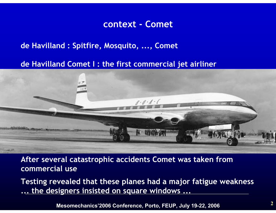
de Havilland : Spitfire, Mosquito, ..., Comet
de Havilland Comet I : the first commercial jet airliner
context - Comet
After several catastrophic accidents Comet was taken from commercial use
Testing revealed that these planes had a major fatigue weakness ... the designers insisted on square windows ...
Mesomechanics’2006 Conference, Porto, FEUP, July 19-22, 2006 3
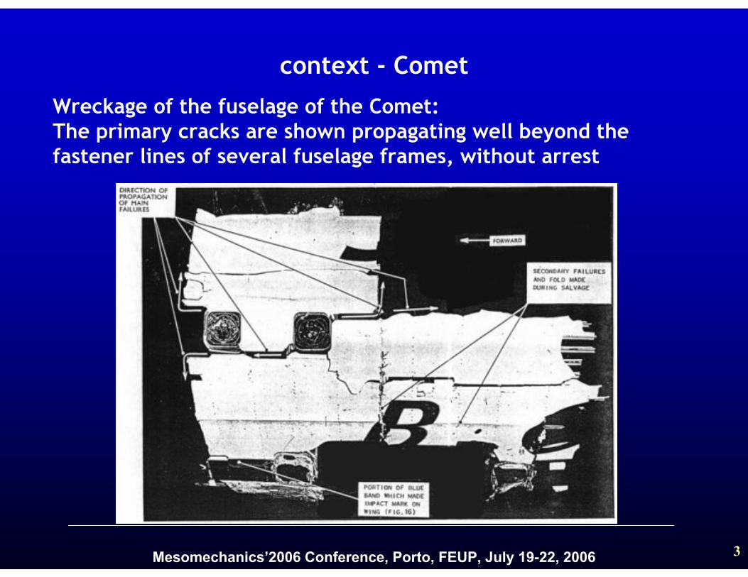
Wreckage of the fuselage of the Comet:The primary cracks are shown propagating well beyond the fastener lines of several fuselage frames, without arrest
context - Comet
Mesomechanics’2006 Conference, Porto, FEUP, July 19-22, 2006 4
……..in order to save costs, the same fuselage that had been tested until the ultimate design load, was later used for the fatigue test. Residual compressive stresses, arising from the ultimate loading, retarded the development of the fatigue cracks
As a result, there were no indications from the fatigue test that the fuselage design was inadequate ……
context - Comet
Abe Brot, ‘Innovation often leads to new problems’, priv. com. Feb 23, 2004
Mesomechanics’2006 Conference, Porto, FEUP, July 19-22, 2006 5
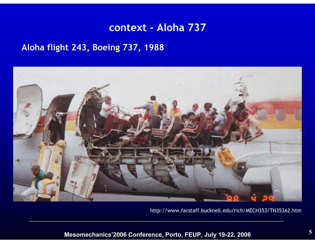
Aloha flight 243, Boeing 737, 1988
http://www.facstaff.bucknell.edu/rich/MECH353/TN353A2.htm
context - Aloha 737

Mesomechanics’2006 Conference, Porto, FEUP, July 19-22, 2006 6
http://www.aloha.net/~icarus/
context - Aloha 737
Mesomechanics’2006 Conference, Porto, FEUP, July 19-22, 2006 7
Presentation outline
1. Cold-worked hole specimens
2. Single rivet lap-joint
3. Lap-joint panel crack growth
modelling
4. Conclusions
Mesomechanics’2006 Conference, Porto, FEUP, July 19-22, 2006 8
Cold worked specimens - contents1.1 What are the questions?
1.2 Geometry and cold working process
1.3 Fatigue tests
1.4 Residual stresses: cold working technique
1.5 Fractography analysis
1.6 Conclusions

Mesomechanics’2006 Conference, Porto, FEUP, July 19-22, 2006 9
1.1 What are the questions?
What is the effect of the residual stress on fatiguecrack initiation?
1) SEM measurements2) Reconstitution of the fatigue life
How do experimental measurements and numericalmodelling of the residual stresses agree?
1) X-Ray measurements2) FEM modelling
Why do the specimens with residual stresses last longer?1) Later crack initiation? 2) Braking effect on crack propagation?
What is the effect of residual stress on the fatigue life?1) S-N

Mesomechanics’2006 Conference, Porto, FEUP, July 19-22, 2006 10
1.2 Geometry and cold working process
Specimen geometry
Cold working process:
Entrance face
Exit face
Material: 2024-T3 Alclad
Mesomechanics’2006 Conference, Porto, FEUP, July 19-22, 2006 11
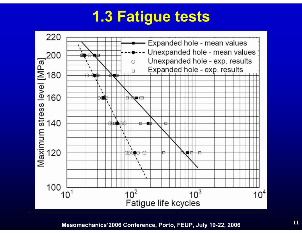
1.3 Fatigue tests
Mesomechanics’2006 Conference, Porto, FEUP, July 19-22, 2006 12
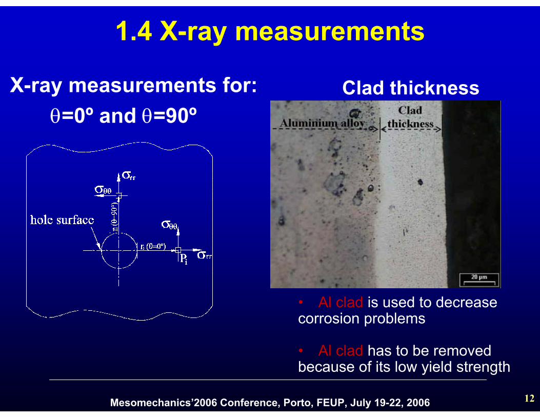
1.4 X-ray measurements
• Al clad is used to decreasecorrosion problems
• Al clad has to be removed because of its low yield strength
X-ray measurements for:θ=0º and θ=90º
Clad thickness
Mesomechanics’2006 Conference, Porto, FEUP, July 19-22, 2006 13
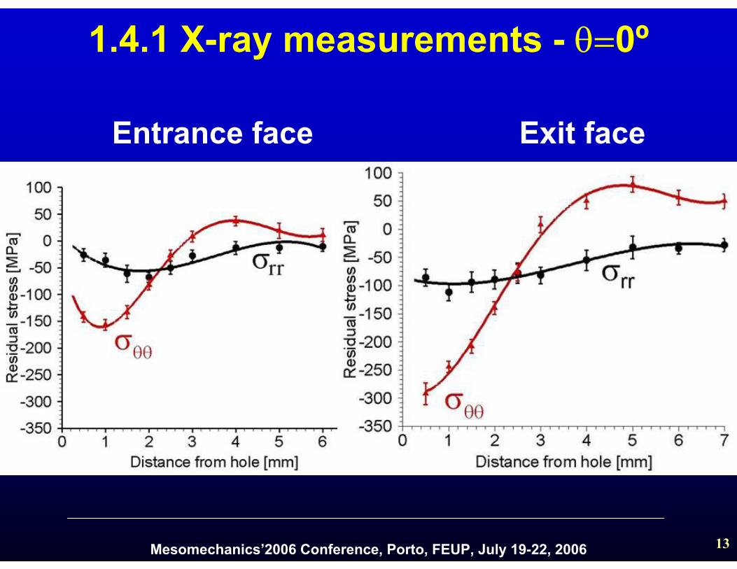
1.4.1 X-ray measurements - θ=0º
Entrance face Exit face
Mesomechanics’2006 Conference, Porto, FEUP, July 19-22, 2006 14
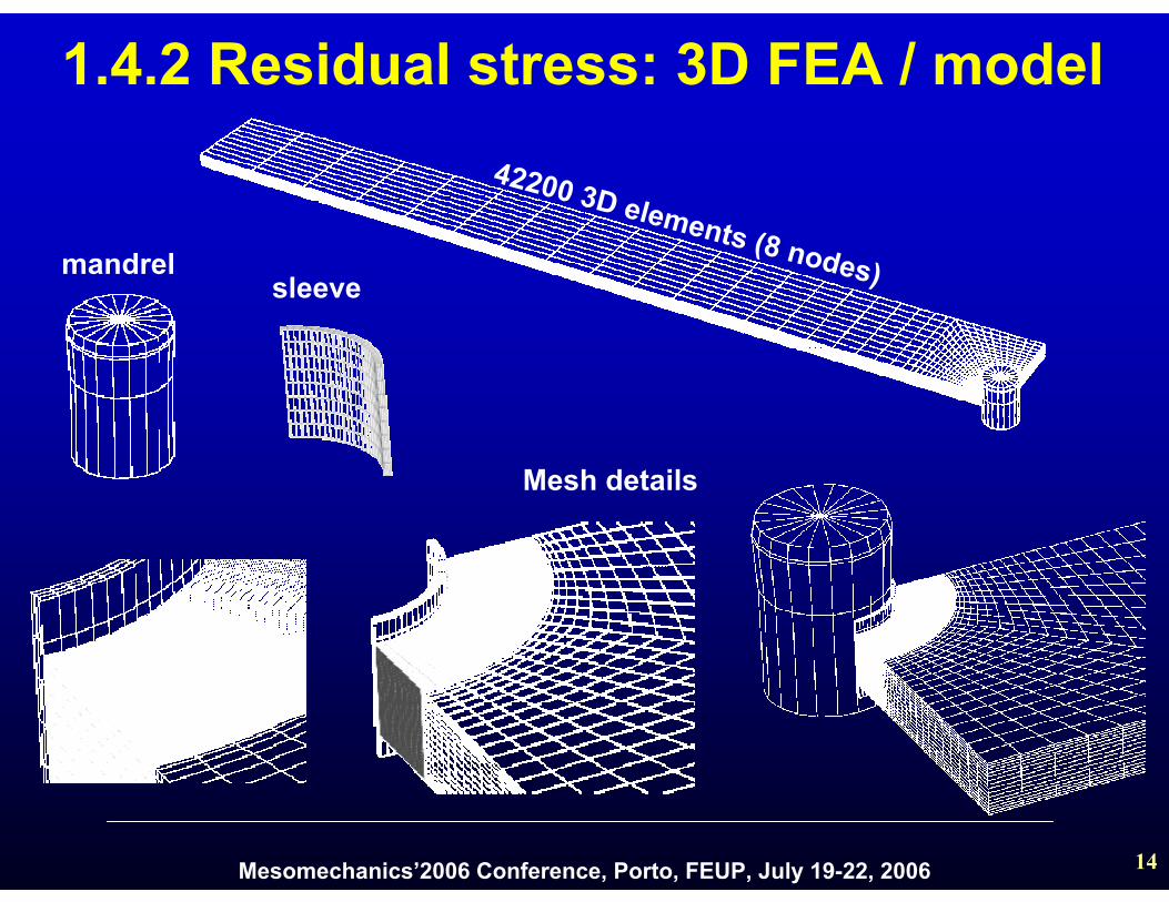
1.4.2 Residual stress: 3D FEA / model42200 3D elements (8 nodes)
Mesh details
mandrelsleeve
Mesomechanics’2006 Conference, Porto, FEUP, July 19-22, 2006 15
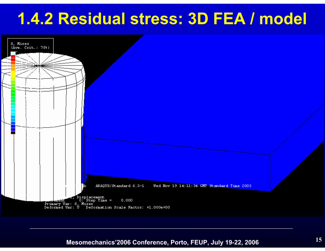
1.4.2 Residual stress: 3D FEA / model
Mesomechanics’2006 Conference, Porto, FEUP, July 19-22, 2006 16
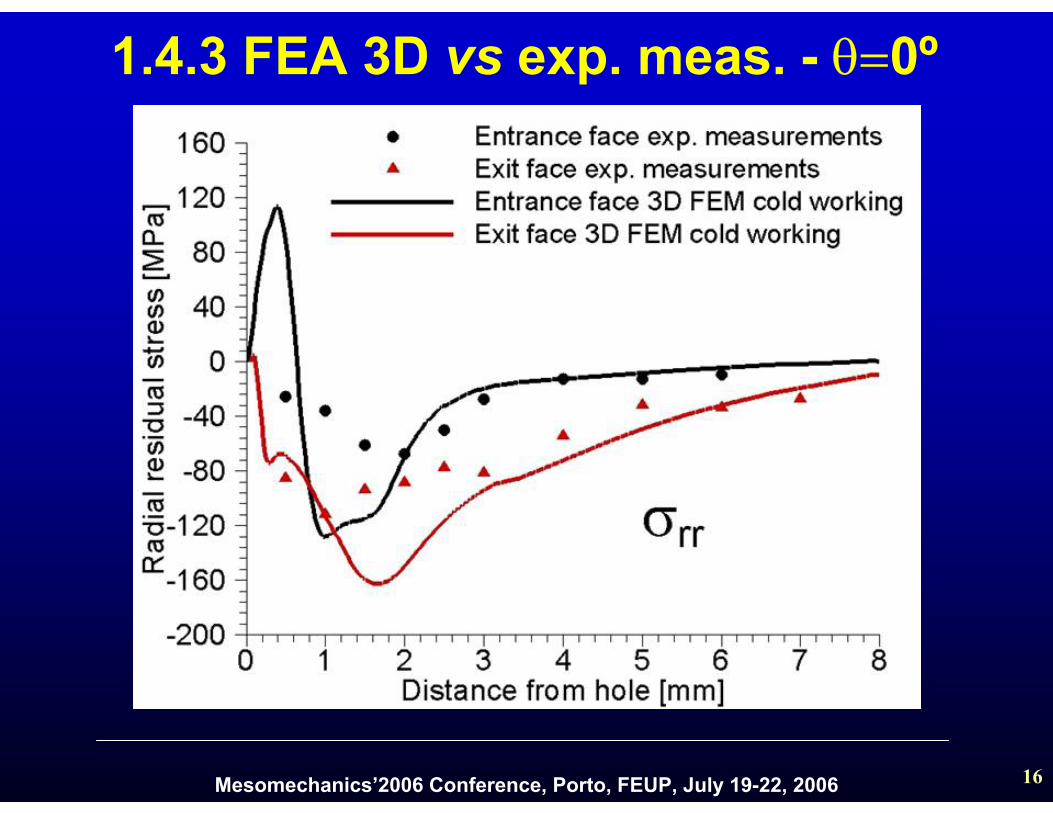
1.4.3 FEA 3D vs exp. meas. - θ=0º
Mesomechanics’2006 Conference, Porto, FEUP, July 19-22, 2006 17
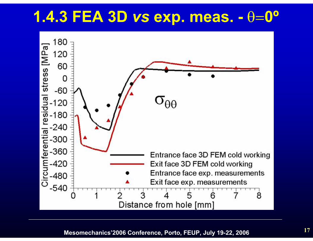
1.4.3 FEA 3D vs exp. meas. - θ=0º
Mesomechanics’2006 Conference, Porto, FEUP, July 19-22, 2006 18
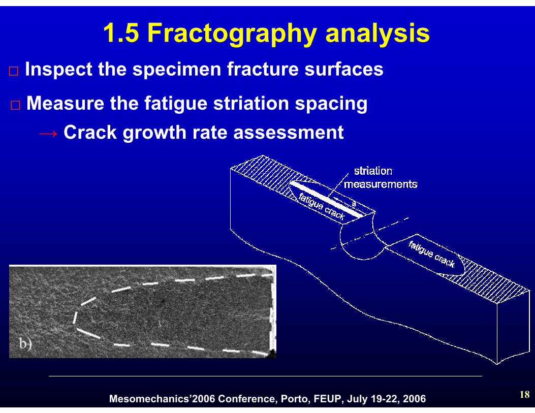
1.5 Fractography analysis □ Inspect the specimen fracture surfaces
→ Crack growth rate assessment□ Measure the fatigue striation spacing
Mesomechanics’2006 Conference, Porto, FEUP, July 19-22, 2006 19
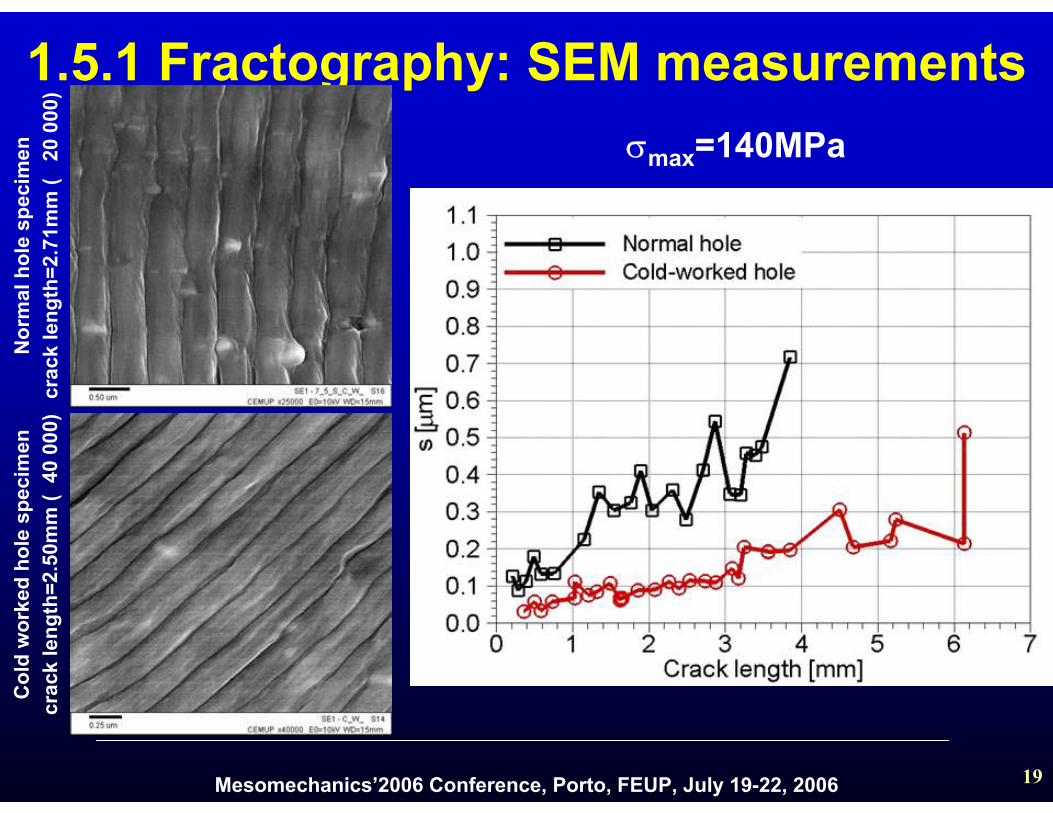
1.5.1 Fractography: SEM measurements σmax=140MPa
Nor
mal
hol
e sp
ecim
encr
ack
leng
th=2
.71m
m (
20
000)
Col
d w
orke
d ho
le s
peci
men
crac
k le
ngth
=2.5
0mm
( 4
0 00
0)
×
×

Mesomechanics’2006 Conference, Porto, FEUP, July 19-22, 2006 20
1.5.1 Fractographic analysis
σmax=120MPa σmax=160MPa
σmax=180MPa
σmax=200MPa
Mesomechanics’2006 Conference, Porto, FEUP, July 19-22, 2006 21
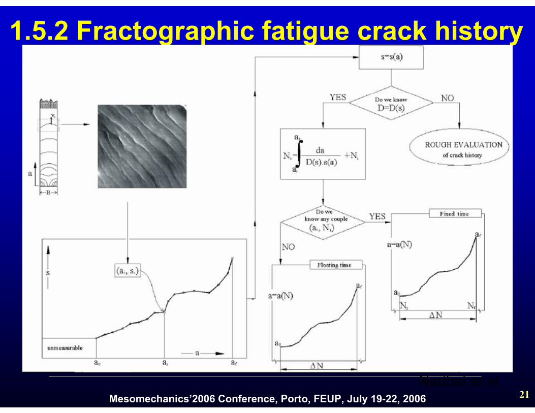
1.5.2 Fractographic fatigue crack history
Nedbal et al.

Mesomechanics’2006 Conference, Porto, FEUP, July 19-22, 2006 22
1.5.2 D-factor: fat. crack history recons.D reflects the interactions of different micromechanisms on the crack front linking micro and macro features of the fatigue process.
D-factor depends essentially on three simultaneously interaction factors:
□ the existence of idle cycles;
□ spatial dispersion of localdirections of crack growth;
□ influence of fatigue crack growthmechanisms other than the striating one.

Mesomechanics’2006 Conference, Porto, FEUP, July 19-22, 2006 23
1.5.3 Surface crack measurements
Mesomechanics’2006 Conference, Porto, FEUP, July 19-22, 2006 24
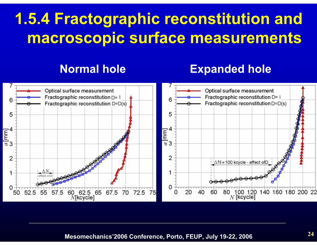
1.5.4 Fractographic reconstitution and macroscopic surface measurements
Normal hole Expanded hole
Mesomechanics’2006 Conference, Porto, FEUP, July 19-22, 2006 25
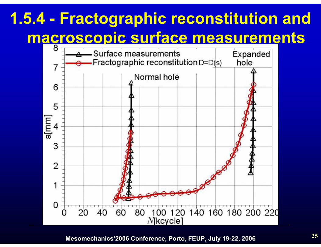
1.5.4 - Fractographic reconstitution and macroscopic surface measurements
Mesomechanics’2006 Conference, Porto, FEUP, July 19-22, 2006 26
1. X-ray technique measurements1.6 Conclusions
□ Inevitably the stresses are averaged over theirradiated volume of material
□ It is not possible to resolve the steep stress gradients in the vicinity of the hole
□ The peak values predicted by FEM are averagedout in the X-ray measurements
2. FEM simulations
□ FEM simulations are in general good agreement with experimental measurements
Mesomechanics’2006 Conference, Porto, FEUP, July 19-22, 2006 27
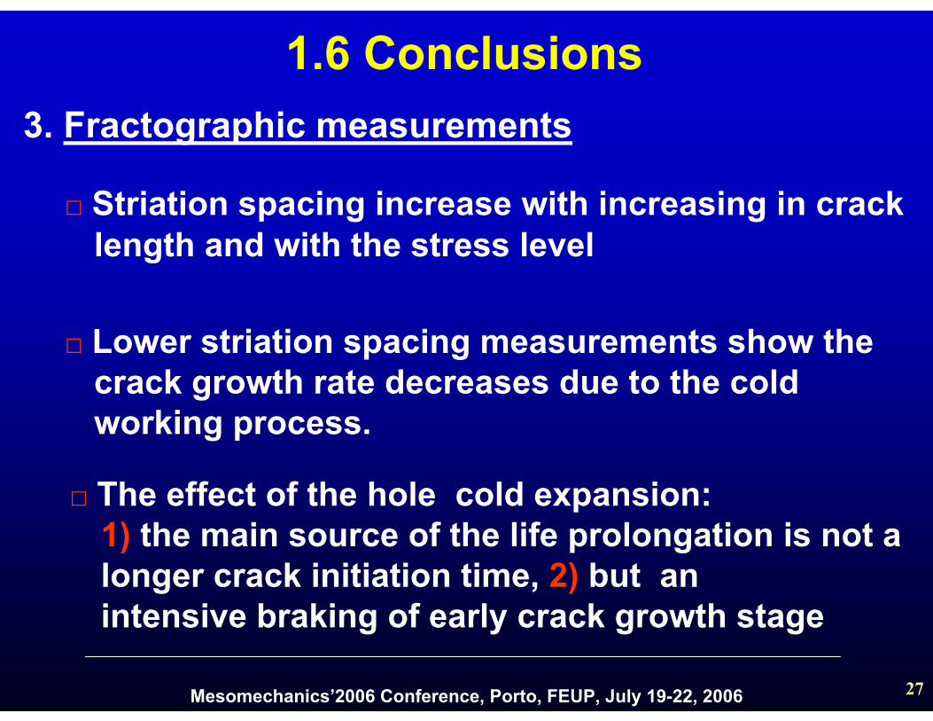
1.6 Conclusions
□ Striation spacing increase with increasing in cracklength and with the stress level
□ Lower striation spacing measurements show thecrack growth rate decreases due to the cold working process.
□ The effect of the hole cold expansion: 1) the main source of the life prolongation is not alonger crack initiation time, 2) but anintensive braking of early crack growth stage
3. Fractographic measurements
Mesomechanics’2006 Conference, Porto, FEUP, July 19-22, 2006 28
2. Single rivet lap-joint – contents
2.1 Geometry
2.2 SEM analysis
2.3 Stress intensity factor calibration
2.4 Load transfer
2.5 Conclusions

Mesomechanics’2006 Conference, Porto, FEUP, July 19-22, 2006 29
specimen type: lap splice with 3 rivet rows and 1 rivet columnmaterial: 2024-T3 Alclad sheetssheet thickness: 1.2 mmspecimen length: 260 mm, 60 mm overlapspecimen width: 20 mmrivets: 2117-T4, ∅ 3.2 x 6.4 mmriveting force: according to typical production standards
2.1 Specimens geometry
Mesomechanics’2006 Conference, Porto, FEUP, July 19-22, 2006 30
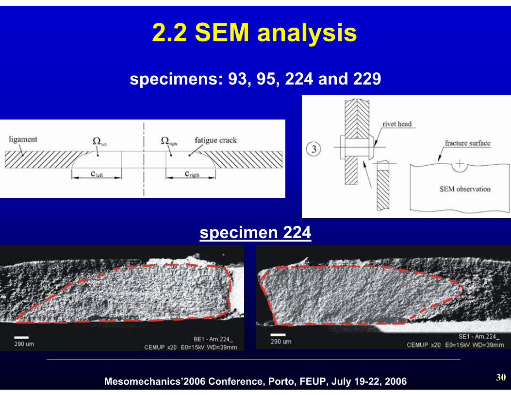
specimens: 93, 95, 224 and 229
specimen 224
2.2 SEM analysis
Mesomechanics’2006 Conference, Porto, FEUP, July 19-22, 2006 31
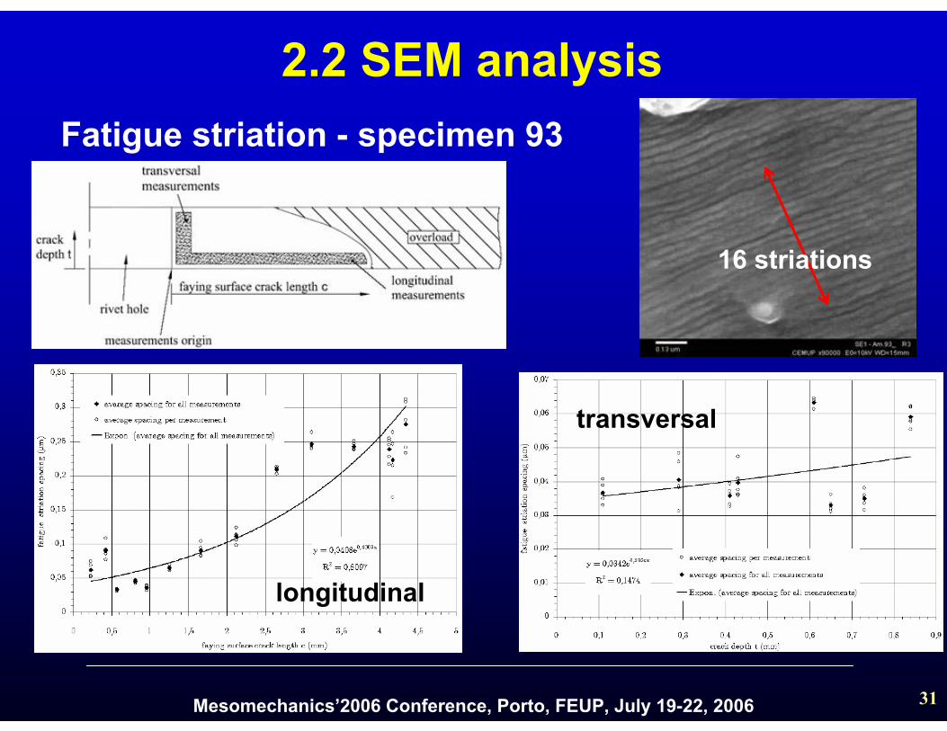
longitudinal
transversal
Fatigue striation - specimen 93
16 striations
2.2 SEM analysis
Mesomechanics’2006 Conference, Porto, FEUP, July 19-22, 2006 32
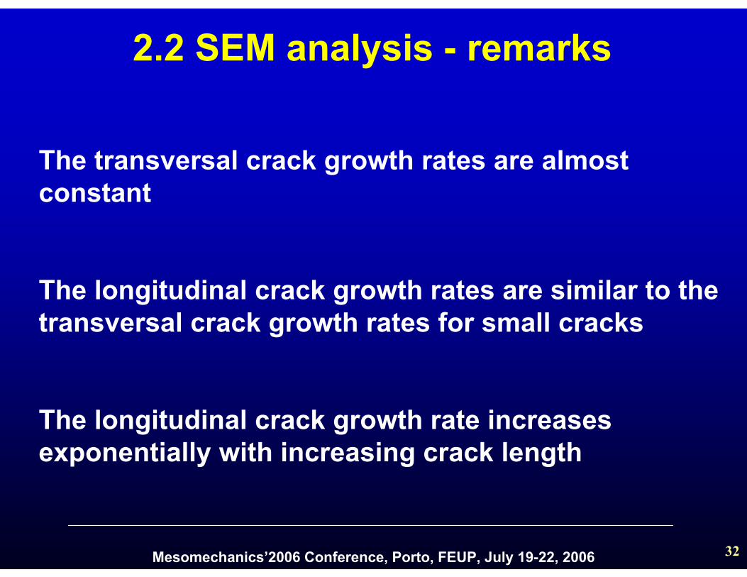
The transversal crack growth rates are almostconstant
The longitudinal crack growth rates are similar to thetransversal crack growth rates for small cracks
The longitudinal crack growth rate increasesexponentially with increasing crack length
2.2 SEM analysis - remarks
Mesomechanics’2006 Conference, Porto, FEUP, July 19-22, 2006 33
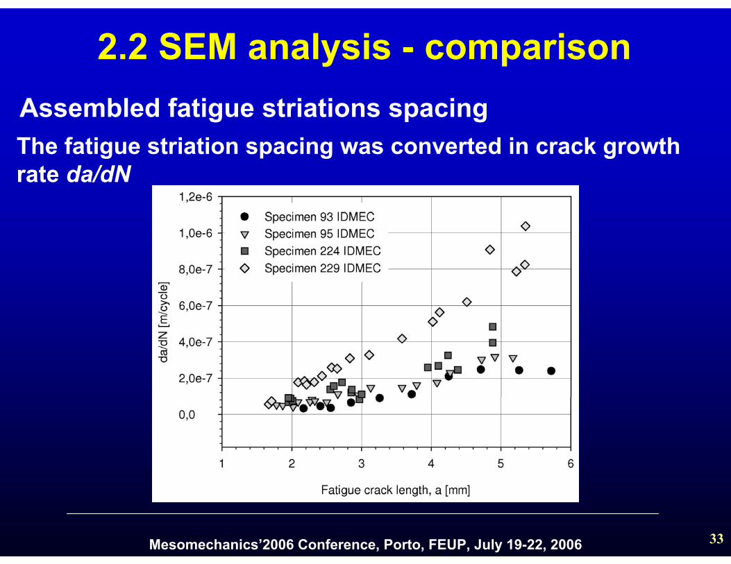
Assembled fatigue striations spacingThe fatigue striation spacing was converted in crack growth rate da/dN
2.2 SEM analysis - comparison

Mesomechanics’2006 Conference, Porto, FEUP, July 19-22, 2006 34
3D Mesh detail
Boundary constraints
Rivets8-node brick elements (C3D8)
7344 elements
Plates20-node brick isoparametric elements (C3D20)7296 elements
2.3 Stress intensity factor calibration using FEM
Mesomechanics’2006 Conference, Porto, FEUP, July 19-22, 2006 35
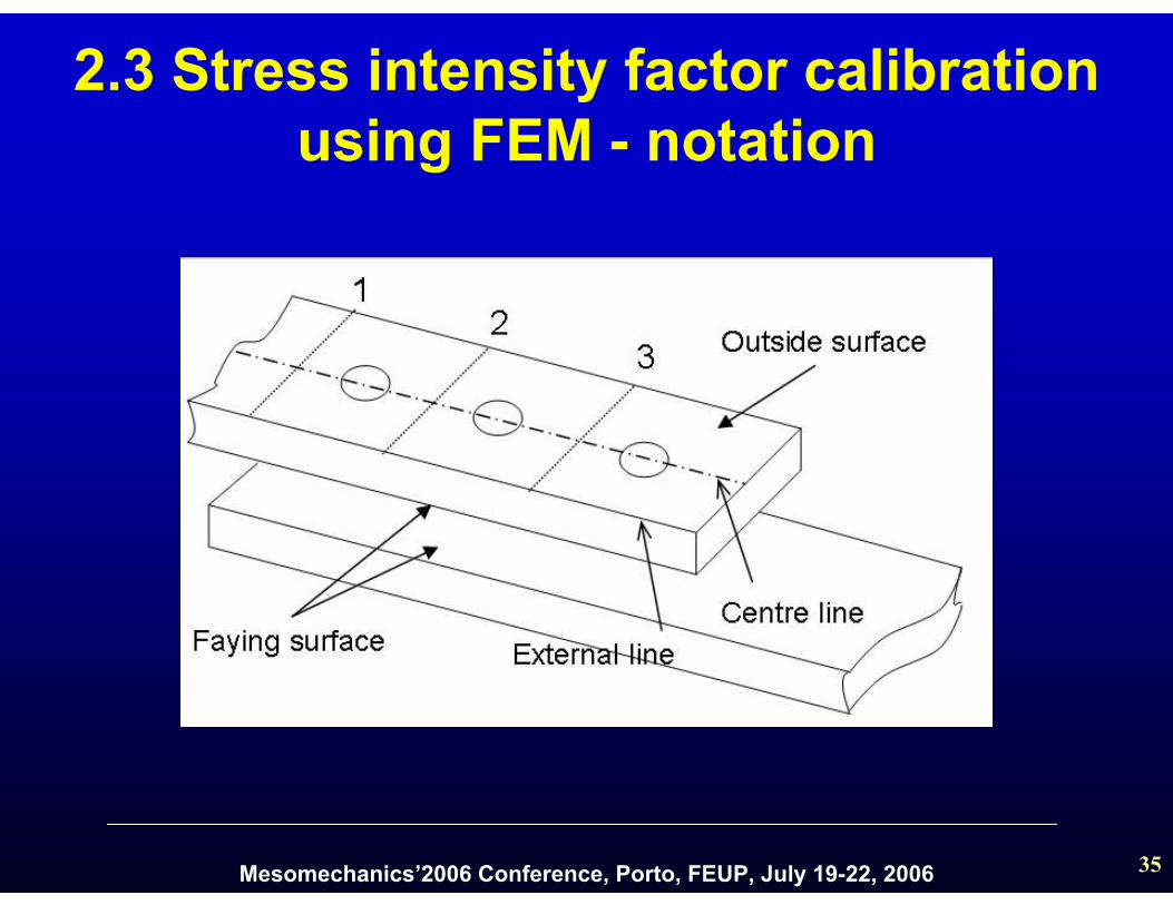
2.3 Stress intensity factor calibration using FEM - notation
Mesomechanics’2006 Conference, Porto, FEUP, July 19-22, 2006 36
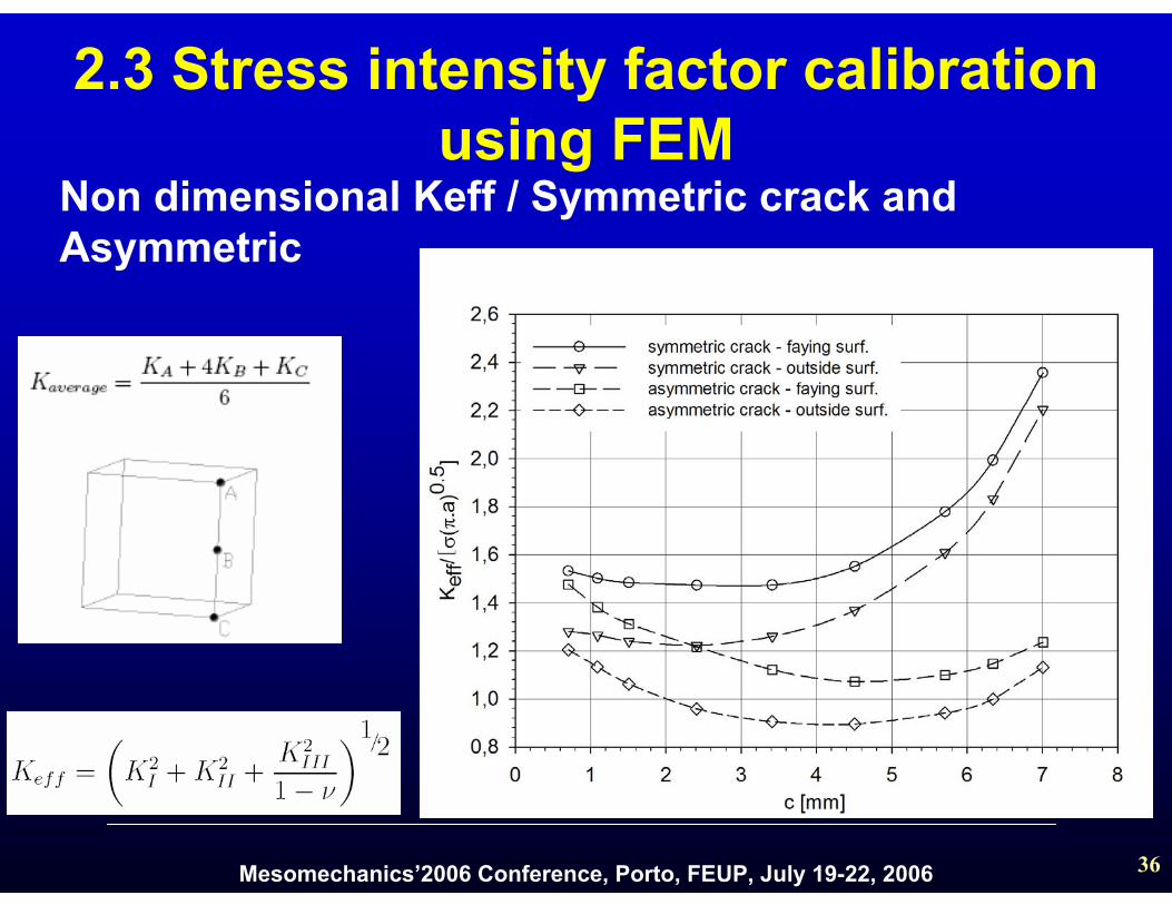
Non dimensional Keff / Symmetric crack and Asymmetric
2.3 Stress intensity factor calibration using FEM
Mesomechanics’2006 Conference, Porto, FEUP, July 19-22, 2006 37
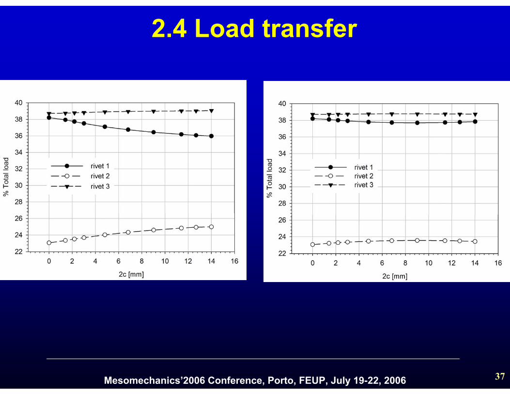
2.4 Load transfer
Mesomechanics’2006 Conference, Porto, FEUP, July 19-22, 2006 38
2.5 Conclusions
□ Striation spacing increase with increasing in cracklength and approximately constant along thethickness
□ the stress intensity factor calibration for a symmetric and asymmetric crack was presented
□ the load transfer behaviour for different crack lengths, for the case of a symmetric and asymmetric crack, was presented
Mesomechanics’2006 Conference, Porto, FEUP, July 19-22, 2006 39
3. Lap-joint crack growth simulationcontents
3.1 Geometry
3.2 Franc2D/L model
3.3 Crack growth
3.4 Crack growth results
3.5 Conclusions

Mesomechanics’2006 Conference, Porto, FEUP, July 19-22, 2006 40
3.1 Lap-joint - geometry
Cavallini, G. and R. Lazzeri, Report on experimental fatigue crack growth in medium and complexcomponents. ADMIRE project report: ADMIRE-TR-3.0-67-3.1/UP, 2003, Dipartimento di Ingegneria, Università diPisa
Mesomechanics’2006 Conference, Porto, FEUP, July 19-22, 2006 41
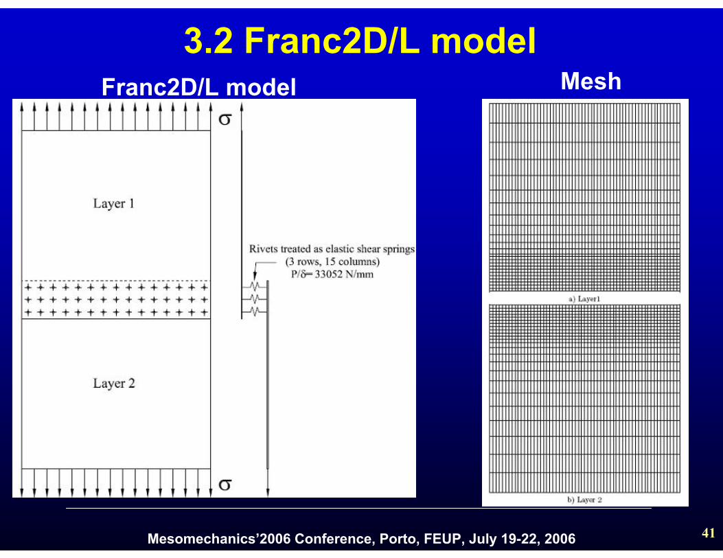
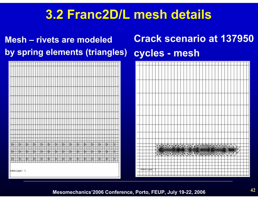
3.2 Franc2D/L modelMeshFranc2D/L model
Mesomechanics’2006 Conference, Porto, FEUP, July 19-22, 2006 42
Mesh – rivets are modeled by spring elements (triangles)
Crack scenario at 137950cycles - mesh
3.2 Franc2D/L mesh details

Mesomechanics’2006 Conference, Porto, FEUP, July 19-22, 2006 43
3.3 Crack growth inspected sites
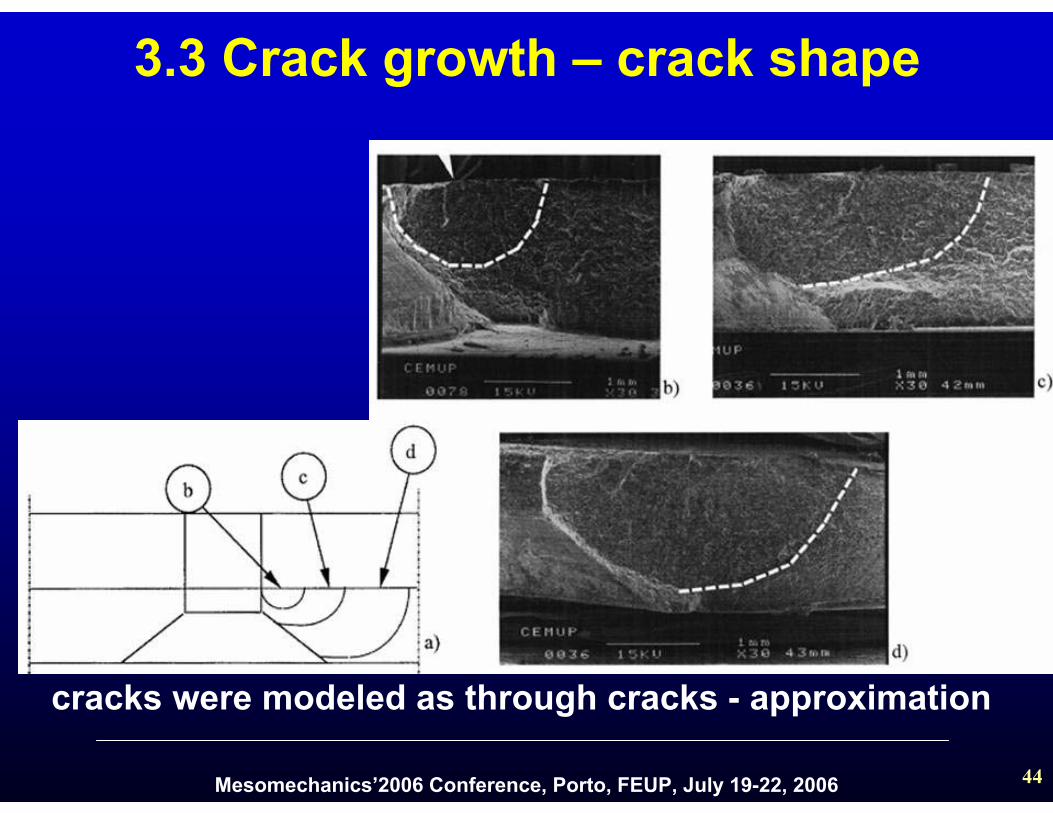
crack shape – experimentallyobserved
Mesomechanics’2006 Conference, Porto, FEUP, July 19-22, 2006 44
3.3 Crack growth – crack shape
cracks were modeled as through cracks - approximation
Mesomechanics’2006 Conference, Porto, FEUP, July 19-22, 2006 45
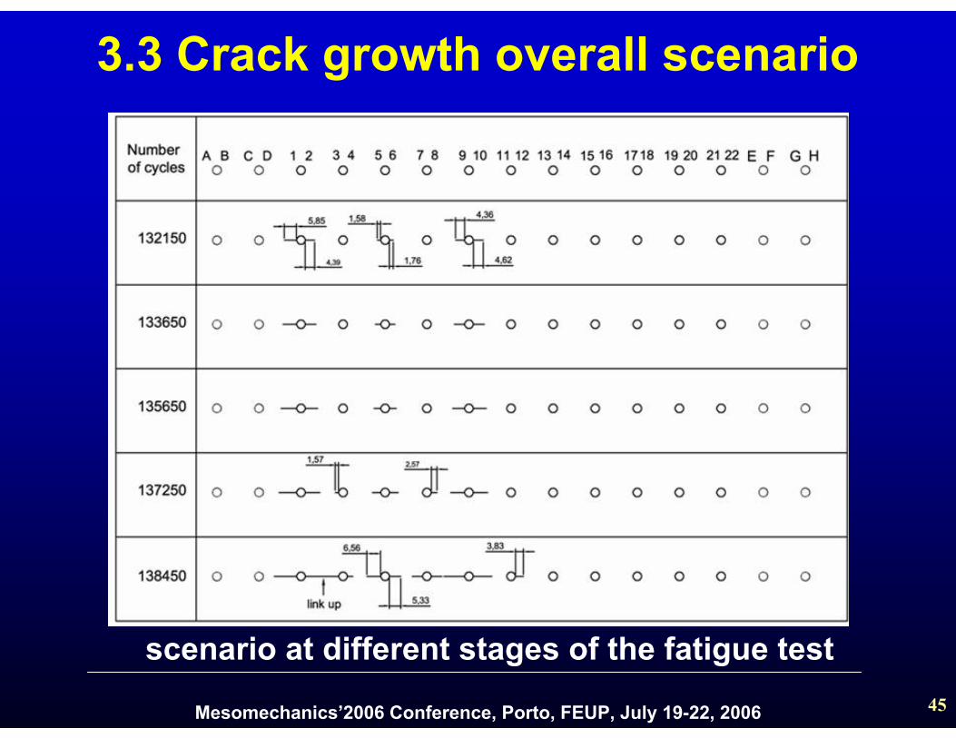
scenario at different stages of the fatigue test
3.3 Crack growth overall scenario
Mesomechanics’2006 Conference, Porto, FEUP, July 19-22, 2006 46
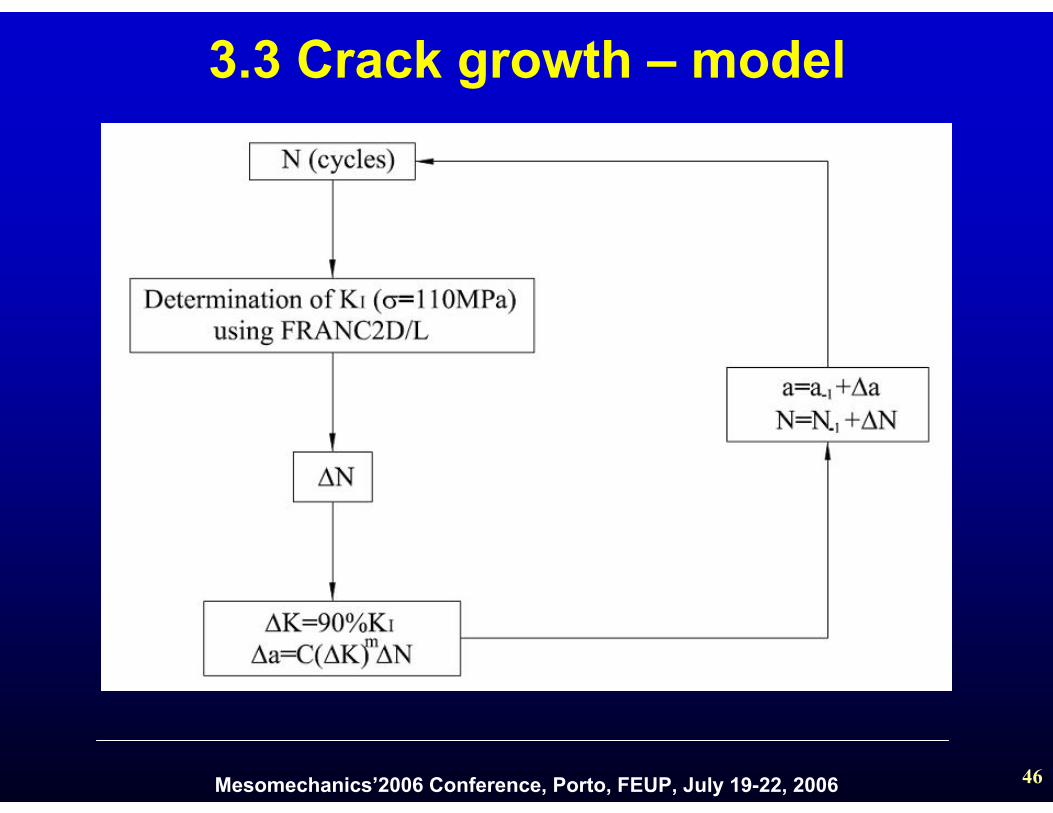
3.3 Crack growth – model
Mesomechanics’2006 Conference, Porto, FEUP, July 19-22, 2006 47
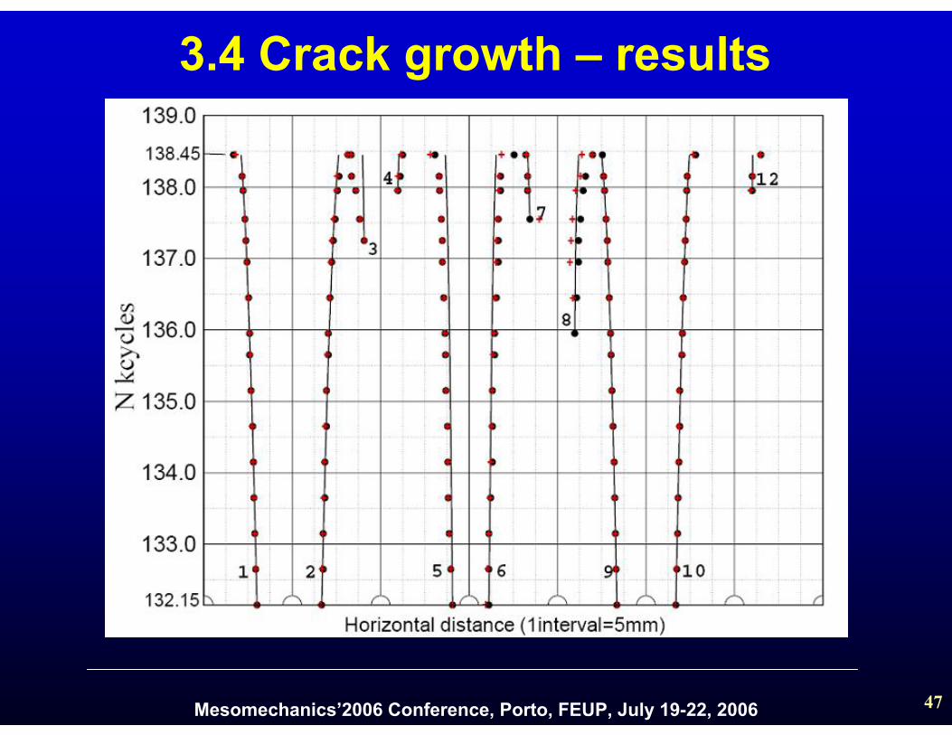
3.4 Crack growth – results
Mesomechanics’2006 Conference, Porto, FEUP, July 19-22, 2006 48
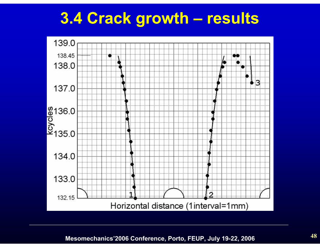
3.4 Crack growth – results
Mesomechanics’2006 Conference, Porto, FEUP, July 19-22, 2006 49
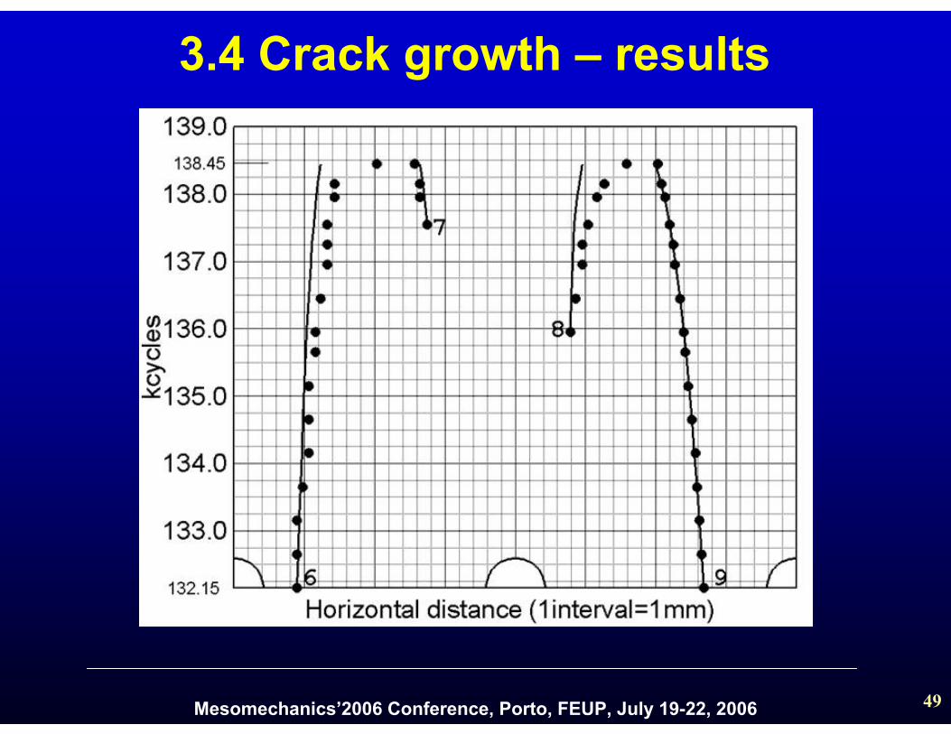
3.4 Crack growth – results
Mesomechanics’2006 Conference, Porto, FEUP, July 19-22, 2006 50
L1
L
L3
Lc
L2
p
sd
eb
ei
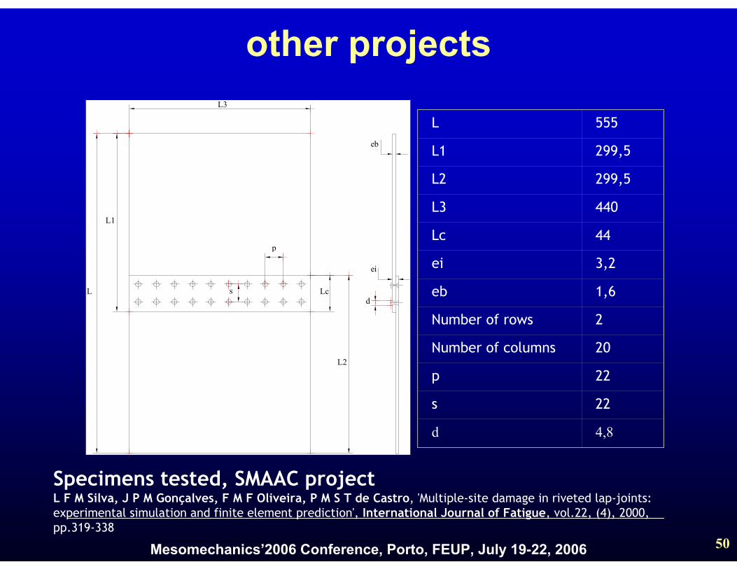
L 555
L1 299,5
L2 299,5
L3 440
Lc 44
ei 3,2
eb 1,6
Number of rows 2
Number of columns 20
p 22
s 22
d 4,8
other projects
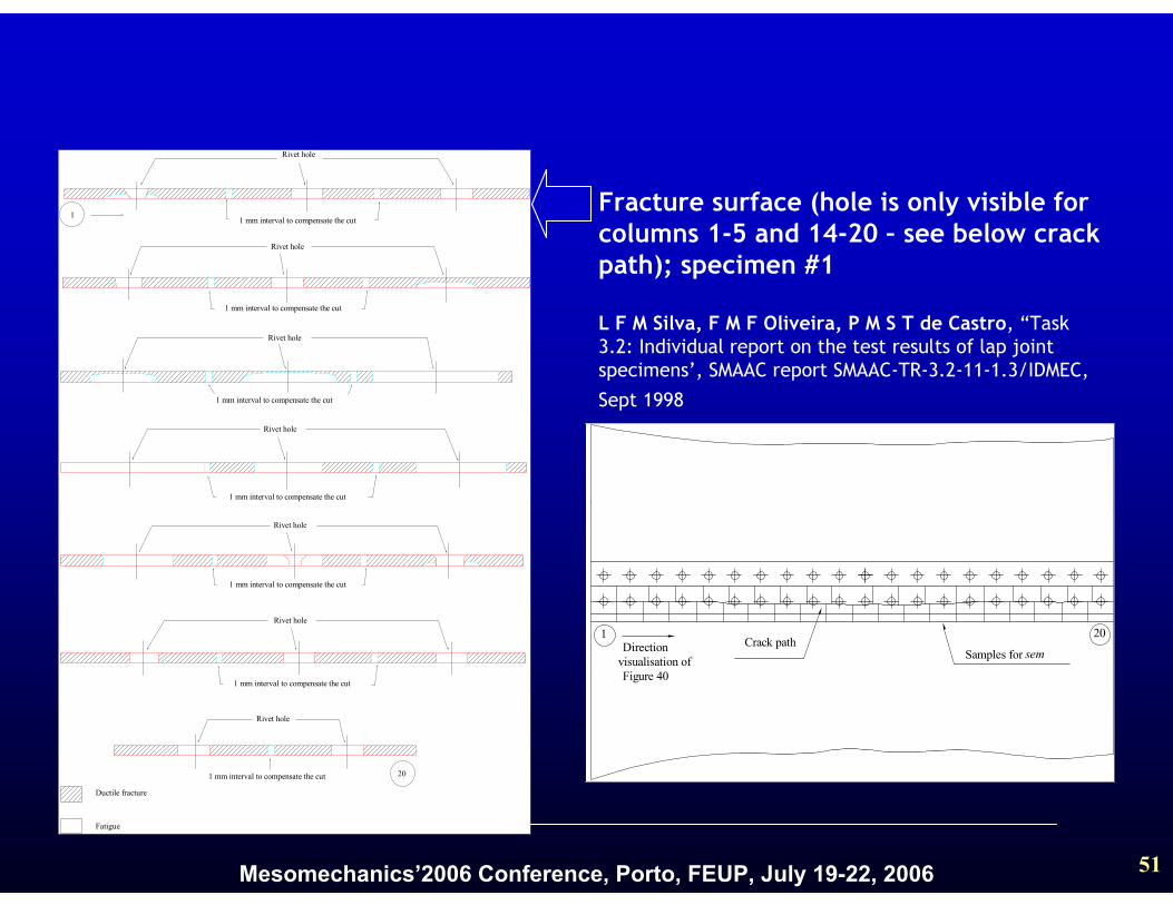
Specimens tested, SMAAC projectL F M Silva, J P M Gonçalves, F M F Oliveira, P M S T de Castro, 'Multiple-site damage in riveted lap-joints: experimental simulation and finite element prediction', International Journal of Fatigue, vol.22, (4), 2000, pp.319-338
Mesomechanics’2006 Conference, Porto, FEUP, July 19-22, 2006 51
Ductile fracture
Fatigue
1
20
Rivet hole
1 mm interval to compensate the cut
Rivet hole
1 mm interval to compensate the cut
Rivet hole
1 mm interval to compensate the cut
Rivet hole
1 mm interval to compensate the cut
Rivet hole
1 mm interval to compensate the cut
Rivet hole
1 mm interval to compensate the cut
Rivet hole
1 mm interval to compensate the cut
Crack pathSamples for sem
1 20Direction
visualisation ofFigure 40
Fracture surface (hole is only visible for columns 1-5 and 14-20 – see below crack path); specimen #1
L F M Silva, F M F Oliveira, P M S T de Castro, “Task3.2: Individual report on the test results of lap jointspecimens’, SMAAC report SMAAC-TR-3.2-11-1.3/IDMEC,
Sept 1998

Mesomechanics’2006 Conference, Porto, FEUP, July 19-22, 2006 52
L F M Silva, J P M Gonçalves, F M F Oliveira, P M S T de Castro, 'Multiple-site damage in riveted lap-joints: experimental simulation and finite element prediction', International Journal of Fatigue, vol.22, (4), 2000,
pp.319-338
Fracture surface; specimen #3
Mesomechanics’2006 Conference, Porto, FEUP, July 19-22, 2006 53
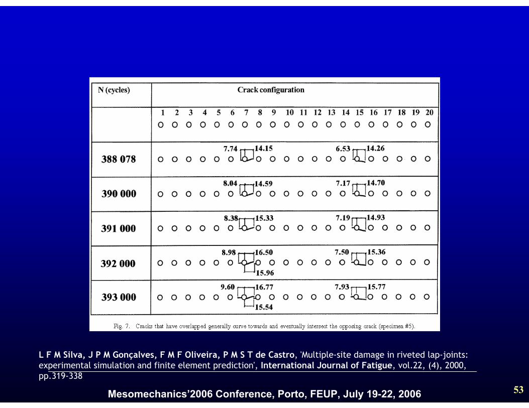
L F M Silva, J P M Gonçalves, F M F Oliveira, P M S T de Castro, 'Multiple-site damage in riveted lap-joints: experimental simulation and finite element prediction', International Journal of Fatigue, vol.22, (4), 2000, pp.319-338
Mesomechanics’2006 Conference, Porto, FEUP, July 19-22, 2006 54
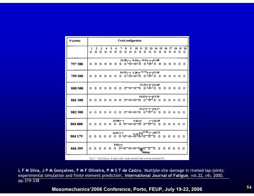
L F M Silva, J P M Gonçalves, F M F Oliveira, P M S T de Castro, 'Multiple-site damage in riveted lap-joints: experimental simulation and finite element prediction', International Journal of Fatigue, vol.22, (4), 2000, pp.319-338
Mesomechanics’2006 Conference, Porto, FEUP, July 19-22, 2006 55
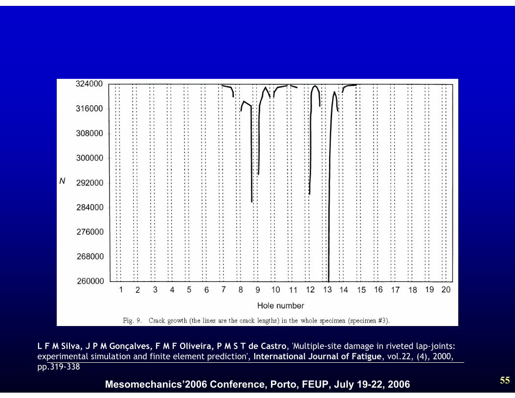
L F M Silva, J P M Gonçalves, F M F Oliveira, P M S T de Castro, 'Multiple-site damage in riveted lap-joints: experimental simulation and finite element prediction', International Journal of Fatigue, vol.22, (4), 2000, pp.319-338
Mesomechanics’2006 Conference, Porto, FEUP, July 19-22, 2006 56
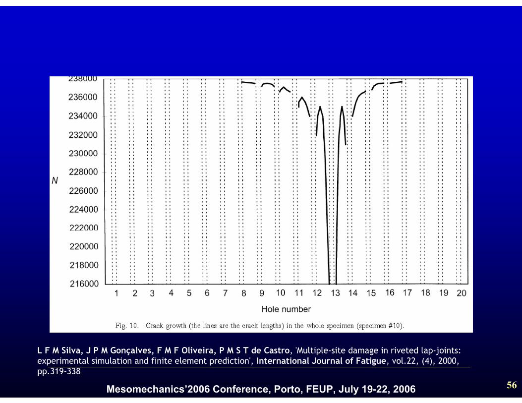
L F M Silva, J P M Gonçalves, F M F Oliveira, P M S T de Castro, 'Multiple-site damage in riveted lap-joints: experimental simulation and finite element prediction', International Journal of Fatigue, vol.22, (4), 2000, pp.319-338
Mesomechanics’2006 Conference, Porto, FEUP, July 19-22, 2006 57
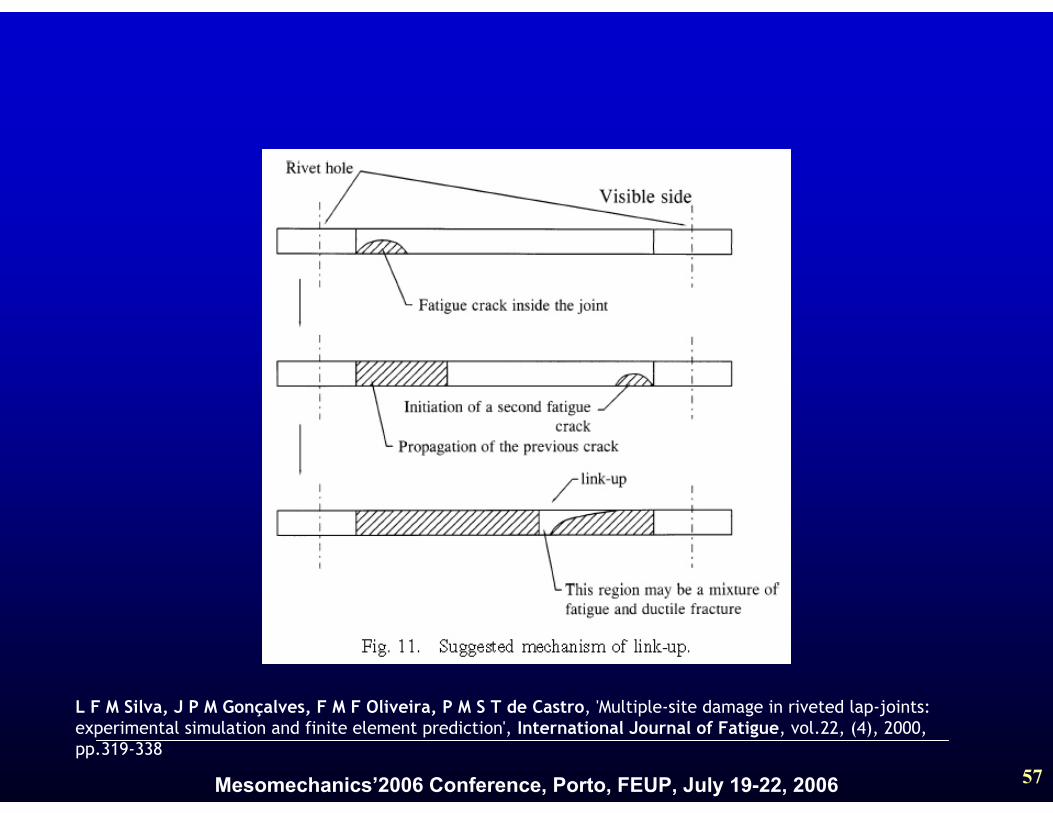
L F M Silva, J P M Gonçalves, F M F Oliveira, P M S T de Castro, 'Multiple-site damage in riveted lap-joints: experimental simulation and finite element prediction', International Journal of Fatigue, vol.22, (4), 2000, pp.319-338
Mesomechanics’2006 Conference, Porto, FEUP, July 19-22, 2006 58
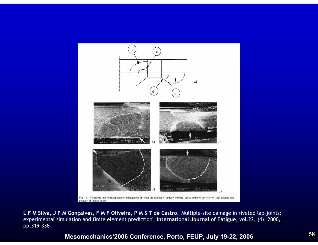
L F M Silva, J P M Gonçalves, F M F Oliveira, P M S T de Castro, 'Multiple-site damage in riveted lap-joints: experimental simulation and finite element prediction', International Journal of Fatigue, vol.22, (4), 2000, pp.319-338
Mesomechanics’2006 Conference, Porto, FEUP, July 19-22, 2006 59
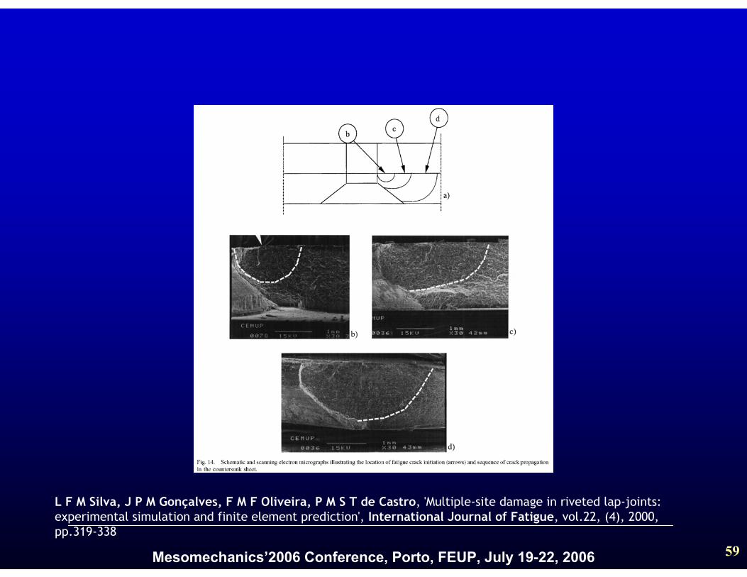
L F M Silva, J P M Gonçalves, F M F Oliveira, P M S T de Castro, 'Multiple-site damage in riveted lap-joints: experimental simulation and finite element prediction', International Journal of Fatigue, vol.22, (4), 2000, pp.319-338
Mesomechanics’2006 Conference, Porto, FEUP, July 19-22, 2006 60
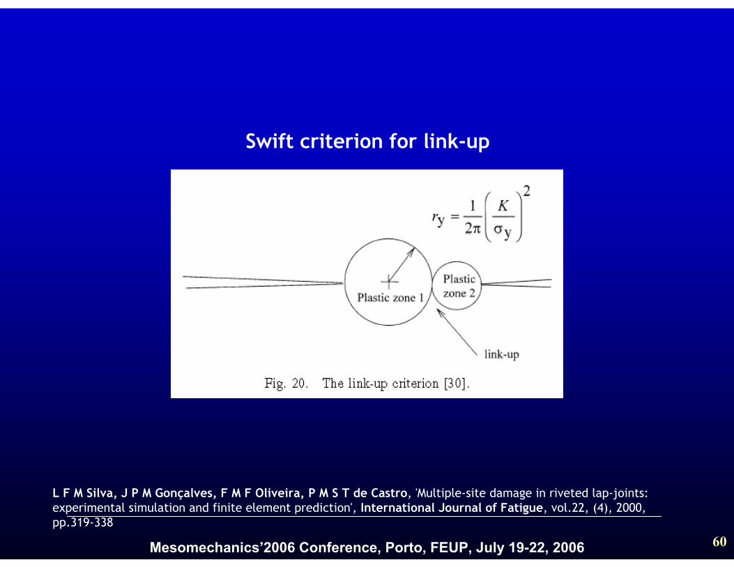
L F M Silva, J P M Gonçalves, F M F Oliveira, P M S T de Castro, 'Multiple-site damage in riveted lap-joints: experimental simulation and finite element prediction', International Journal of Fatigue, vol.22, (4), 2000, pp.319-338
Swift criterion for link-up
Mesomechanics’2006 Conference, Porto, FEUP, July 19-22, 2006 61
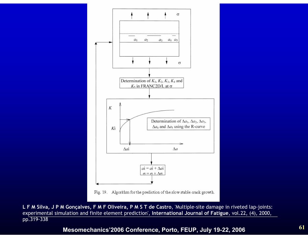
L F M Silva, J P M Gonçalves, F M F Oliveira, P M S T de Castro, 'Multiple-site damage in riveted lap-joints: experimental simulation and finite element prediction', International Journal of Fatigue, vol.22, (4), 2000, pp.319-338
Mesomechanics’2006 Conference, Porto, FEUP, July 19-22, 2006 62
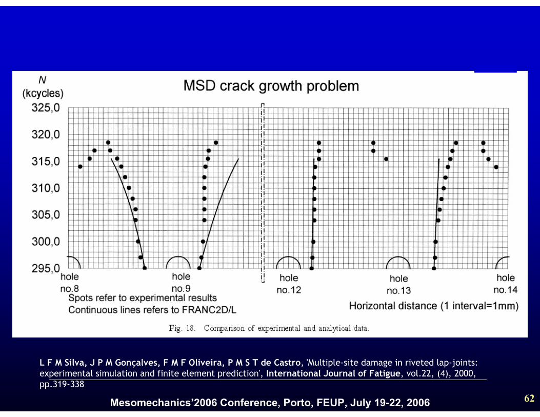
L F M Silva, J P M Gonçalves, F M F Oliveira, P M S T de Castro, 'Multiple-site damage in riveted lap-joints: experimental simulation and finite element prediction', International Journal of Fatigue, vol.22, (4), 2000, pp.319-338
Mesomechanics’2006 Conference, Porto, FEUP, July 19-22, 2006 63
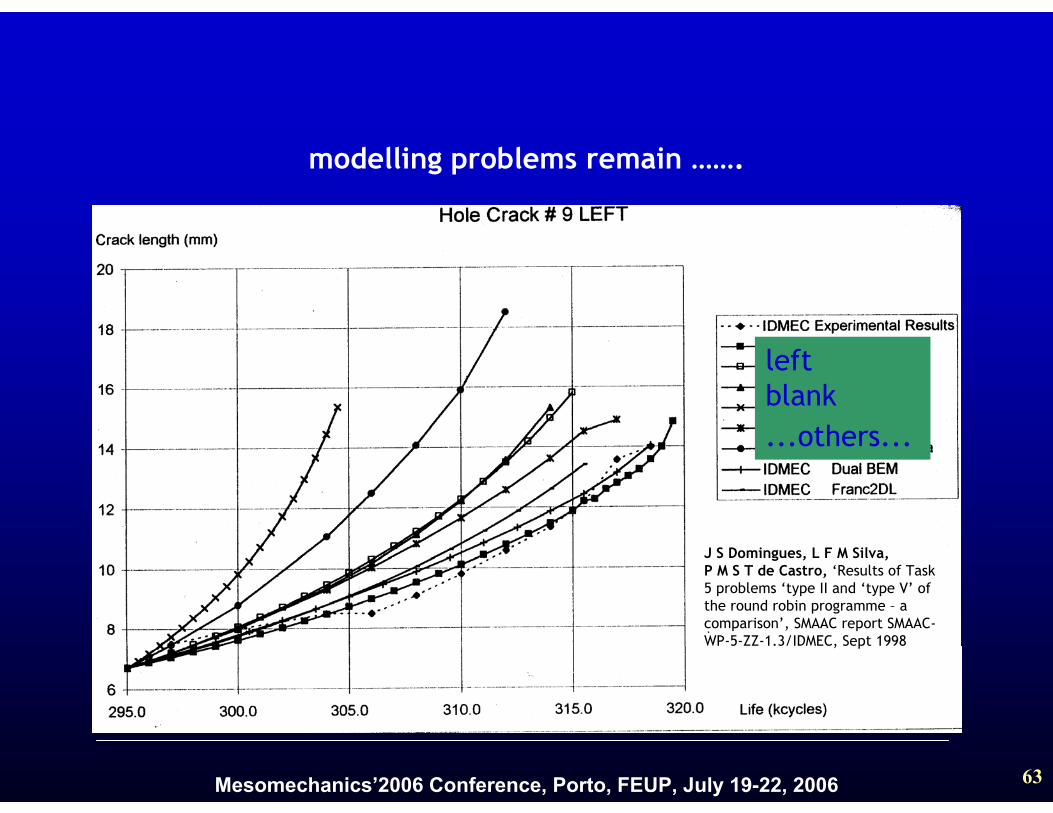
leftblank...others...
modelling problems remain …….
J S Domingues, L F M Silva,P M S T de Castro, ‘Results of Task5 problems ‘type II and ‘type V’ of the round robin programme – a comparison’, SMAAC report SMAAC-WP-5-ZZ-1.3/IDMEC, Sept 1998
Mesomechanics’2006 Conference, Porto, FEUP, July 19-22, 2006 64
3.5 Lap - joint conclusions
□ Crack growth modelling was done in a lap-joint panel from 132150 to 138450 cycles;
□ A good agreement was found between theexperimentation and the prediction of FRANC2D/Lbased on the Paris Law;
Limitations:□ Cracks grow with an elliptical shape and not as
through cracks;□ Rivets were treated as spring elements. It is only a
simplification that has some limitations
Mesomechanics’2006 Conference, Porto, FEUP, July 19-22, 2006 65
4. Conclusions – open hole□ The improvement of the fatigue live due to the cold
working process was quantified
□ The assessment of the residual stresses using the X-ray diffraction and FEM modelling are in general good agreement
□ Striation spacing increase with increasing incrack length and with the stress level
□ Lower striation spacing meas. show the crack growth rate decreases due to cold expansion
Mesomechanics’2006 Conference, Porto, FEUP, July 19-22, 2006 66
□ Striation spacing increase with increasing in cracklength and approximately constant along thethickness
□ the stress intensity factor calibration for a symmetric and asymmetric crack was presented
□ the load transfer behaviour for different crack lengths for the case of a symmetric and asymmetric crack was presented
4. Conclusions – single rivet lap-joint
Mesomechanics’2006 Conference, Porto, FEUP, July 19-22, 2006 67
□ Crack growth in a lap-joint panel was modeled
□ A good agreement was found between theexperimentation and the prediction of FRANC2D/Lbased on the Paris Law;
Limitations:
□ Cracks grow with an elliptical shape and not as through cracks;
□ Rivets were treated as spring elements. It is only a simplification that has some limitations
4. Conclusions – Lap-joint crack growth modelling
Mesomechanics’2006 Conference, Porto, FEUP, July 19-22, 2006 68
Acknowledgments:
The authors would like to acknowledge inparticular the European Union projects:
• SMAAC project BRITE BE95-1053, leader: Dr Peter Horst (then at DASA - Hamburg)
• ADMIRE project contract no. G4RD-CT-2000-00396, leader: Dr Alfonso Apicella, ALENIA