Patented, Compact, High Performance Medium Voltage … · Patented, Compact, High Performance...
16
Patented, Compact, High Performance Medium Voltage Drive 2.3 to 13.8 kV Class 1500 to 40,000 HP ®
Transcript of Patented, Compact, High Performance Medium Voltage … · Patented, Compact, High Performance...

Patented, Compact, High Performance Medium Voltage Drive
2.3 to 13.8 kV Class1500 to 40,000 HP
®

With over 100 years of experience in motor design and application, TECO-Westinghouse Motor Company is a premier supplier of AC and DC motors and generators. Ranging from fractional HP ratings to 100,000 HP, these high-quality machines are used in a variety of rugged applications across several industries throughout the world.
TECO-Westinghouse comprises the experience of Westinghouse, a leader in the motor industry since 1888, and TECO Electric & Machinery Co, Ltd., a multinational conglomerate with over 50 years of manufacturing experience. Together, TECO-Westinghouse embodies the capabilities and proud traditions of excellence from both companies and carries them forward.
In keeping with this idea, TECO-Westinghouse is pleased to now offer a complete package of Variable Speed Drive (VSD) systems that includes an Input/ Output Switchgear, Medium Voltage Drive (MVD), and motors.
VersaBridge® MVDs provide reliable motor control for a variety of industry specific and general purpose applications including Oil & Gas, Utility/ Power Generation, Metals and Mines. These patented MVDs are designed utilizing a multilevel H-Bridge topology that reduces the harmonic levels to extremely low levels. The modular design facilitates ease of installation, commissioning and maintenance. The VersaBridge® is an innovative product that combines reliable, simple, and compact solutions with the latest power electronics and cooling technologies.
MAIN CHARACTERISTICSModularity: Modular design with common building blocks (Cube, Slices, Mains) makes the VersaBridge® MVD scalable for different power ratings with fewer spare parts. Power Electronics Modules (Cubes) can be easily removed for maintenance.
Quick and Easy Installation: There are configurable power cable entries/exits on the top, bottom, or both. There are no field cabling requirements to connect the assembled Mains and Slice sections.
Serviceability: Modular design requires few spare parts. Additionally, the parts are universal and can be used in any configuration regardless of the voltage or power class.
Multilevel, Cascaded, H-Bridge Topology produces near sinusoidal wave output which reduces motor harmonics and torque pulsation, even at low speeds with virtually no cable length restriction.
Ultra Low Line-Side Harmonics are fully compatible with new or existing motor installations without the need for an external filter and exceed IEEE-519 standard requirements.
Bypass Manual/Automatic: The VersaBridge® MVD has isolating contactors within each Cube. In the event of a fault, contactors will isolate the faulty Slice and allow the MVD to restart, catching the spinning motor.
Flying Start into a Spinning Load: The VersaBridge® MVD offers the ability to catch a spinning load without any torque, voltage, or current having a negative impact on the equipment.
N+1 … N+N Redundancy: In addition to the Slice bypass option, the drive can be configured to have additional redundancy options for continued operation at full rated output power.
Power Dip Ride-Through: The VersaBridge® MVD design provides a five cycle power loss ride-through to keep the process running without the need for auxiliary UPS.
One Drive for Multiple Motors: The VersaBridge® MVD can start multiple motors and transfer them synchronously to utility lines and back to the drive.
Industry Standard Ethernet Modbus Communication: Standard protocol allows the VersaBridge® MVDs to easily communicate with various SCADA or DCS systems.

VersaBridge® Applications
Petrochemical, Oil & Gas Industries Pulp & PaperCompressors PumpsPumps FansFans RefinersMixers Vacuum pumpsAgitators ChipperMetals & Mining CementMills (SAG, Ball, Rolling) PumpsPumps FansFans ConveyorsConveyors KilnsWater/ Wastewater UtilitiesPumps PumpsFans Fans
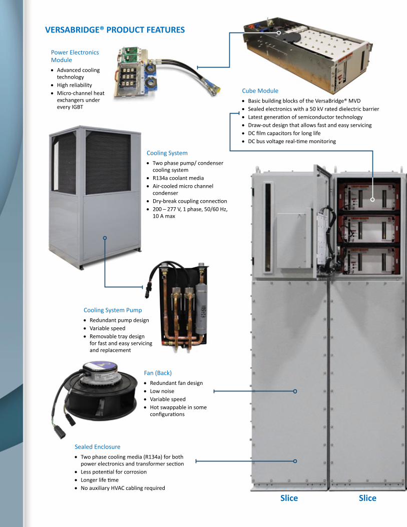
VERSABRIDGE® PRODUCT FEATURES
Cube Module• Basic building blocks of the VersaBridge® MVD• Sealed electronics with a 50 kV rated dielectric barrier• Latest generation of semiconductor technology• Draw-out design that allows fast and easy servicing• DC film capacitors for long life• DC bus voltage real-time monitoring
Fan (Back)• Redundant fan design• Low noise• Variable speed• Hot swappable in some
configurations
Power Electronics Module• Advanced cooling
technology• High reliability• Micro-channel heat
exchangers under every IGBT
Cooling System• Two phase pump/ condenser
cooling system• R134a coolant media• Air-cooled micro channel
condenser• Dry-break coupling connection• 200 – 277 V, 1 phase, 50/60 Hz,
10 A max
Sealed Enclosure• Two phase cooling media (R134a) for both
power electronics and transformer section• Less potential for corrosion• Longer life time• No auxiliary HVAC cabling required
Cooling System Pump• Redundant pump design• Variable speed• Removable tray design
for fast and easy servicing and replacement
SliceSlice
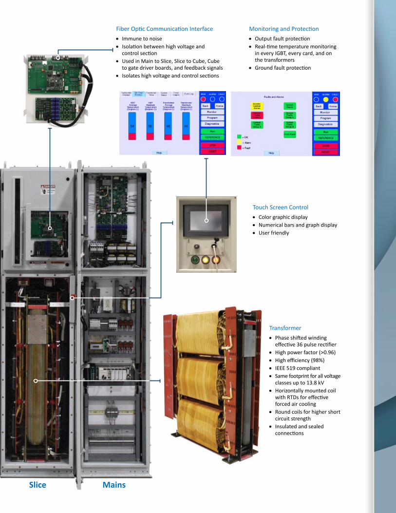
Fiber Optic Communication Interface• Immune to noise• Isolation between high voltage and
control section• Used in Main to Slice, Slice to Cube, Cube
to gate driver boards, and feedback signals• Isolates high voltage and control sections
Monitoring and Protection• Output fault protection• Real-time temperature monitoring
in every IGBT, every card, and on the transformers
• Ground fault protection
Transformer• Phase shifted winding
effective 36 pulse rectifier• High power factor (>0.96)• High efficiency (98%)• IEEE 519 compliant• Same footprint for all voltage
classes up to 13.8 kV• Horizontally mounted coil
with RTDs for effective forced air cooling
• Round coils for higher short circuit strength
• Insulated and sealed connections
Touch Screen Control• Color graphic display• Numerical bars and graph display• User friendly
MainsSlice

SLICE TOPOLOGY
SYSTEM TOPOLOGY
Each VersaBridge® MVD has at least one Mains section and a number of Slices depending on the system configuration. The Mains section includes a customer and motor connection. Each Slice is composed of three Cubes, one Cube for each output phase.
Medium voltage levels are obtained by combining the outputs of multiple low voltage Cubes. Each Slice can provide up to 1380 Vrms. When adding the Slices in series or parallel, different voltage and current levels can be achieved.
For example, a three-phase 4160 V output can be achieved by combining three slices in series as shown to the right. For higher output capabilities, the VersaBridge® topology can be extended to reach 13.8 kV.
Cube 1A1
Cube 2B1
Cube 3C1
M
Cube 1A2
Cube 2B2
Cube 3C2
Cube 1A3
Cube 2B3
Cube 3C3
Main Power Supply (2.3 – 13.8 kV)
Slice 1
Slice 2
Slice 3
0º
+20º
-20º
+5º
0º
-20º
+5º
0º
-20º
-5º
+20º
+20º
*Example: 3000 HP, 4160V Output
TX 1
TX 2
TX 3
A
B
C
TX 1 TX 2 TX 3
Main Power Supply (2.3 – 13.8 kV)
Cube 1
Cube 2
Cube 3
Slice A multilevel cascaded H-Bridge topology produces a near sinusoidal current and voltage waveform. This patented technology utilizes a modular transformer and power electronics cabinet section referred to as a Slice.
The transformer is an integral part of the Slice. Each 18-pulse transformer has either a +5⁰ or -5⁰ phase shift, producing an overall input waveform which is equivalent to a 36 pulse transformer.
The VersaBridge® MVD design meets the most stringent requirements for harmonic distortion as defined by IEEE-519. The topology does not require the installation of additional harmonic filters.
The Slice concept minimizes the installation and site requirements. The VersaBridge® modular design and direct connection to the line configuration can lower the investment and increase the reliability and lifetime of the installation.

CUBE TOPOLOGYEach Cube is a building block of the system. Each VersaBridge® Cube is exactly the same regardless of voltage or power classification. The power electronics module includes AC/DC diode rectifier, DC link film capacitors, and DC/AC H-Bridge inverter section.
From Transformer
Trip Contactor
Cube Power Output
L1
L2
L3
Pre-charge Resistors
Fiber optic control signals from/to Cube control
Fiber optic signals from/to Slice control
Fiber optic signals from/to Mains control
P1P2
Bypass Contactor
Incoming three phase AC voltage (L1, L2, and L3) is rectified by diode rectifier then H-Bridge converts the DC voltage to single phase voltage (P1, P2) using space vector pulse width modulation.
With connecting Cubes in series and phase shifting the output, the VersaBridge® drive can produce multilevel output very close to sinusoidal waveform with ultra-low THDs. Multi-level cascaded H-bridge topology creates high effective switching frequency in inverter output voltage with low IGBT switching frequency. This results in extremely low output current harmonics and increased efficiency from lower switching losses.
The standard pre-charge feature within the Cube utilizes an electronically controlled contactor to avoid high inrush currents at system startup.
Interchangeable Power CubeEvery power Cube is identical and interchangeable regardless of the system rating.
Cubes can be replaced and maintained individually. Straightforward installation and removal of the Cube reduces the downtime and facilitates training for maintenance and operations personnel.

TOUCHSCREEN CONTROLA user-friendly 7” touchscreen display comes as standard for easy configuration and monitoring of the drive. Numerous parameters can be displayed in either numerical or graphical format. Local/ remote connections are available for operations.
AUTOMATIC/ MANUAL BYPASSThe unique topology of the VersaBridge® drives allows for N+1, N+2, … N+N redundant configurations possible by adding more Slices to the system.
Each Cube includes input and output isolation contactors. The MVD can operate at full power even with a failed Slice. In the case of failure, the VersaBridge® control will determine which Slice failed, isolate it from the system by opening the contactors, and restart it into the spinning load as shown below.
In the unlikely event of a Cube failure, the redundancy provided by additional Slices allows the drive to keep running by bypassing the failed Slice(s) for critical applications. This provides higher reliability in the event of component fault or failure.
Slice 1
Slice 3
Slice 2
Redundant Slice (N+1)
M
Mai
n Po
wer
Sup
ply
(2.3
– 1
3.8
kV)
Power Electronics
Power Electronics
Power Electronics
Cube
2Cu
be 3
Cube
1
System Slice

CUSTOM ENGINEERING SOLUTIONSTECO-Westinghouse provides custom engineered systems designed to each customer’s unique specifications. The engineering design process starts with understanding the customer’s machine load during both start-up and steady state operation. TECO-Westinghouse can assist by providing system and arc-flash studies for optimized motor and MVD system configuration.

SERVICE, MAINTENANCE AND TRAINING• The VersaBridge® only has FIVE standard spare parts, including TWO optional spare parts:
1. Mains controls and power supply
2. Slice control panel
3. Slice power supply
4. Cube inverter module
5. Fan assembly
6. Power transformer (optional)
7. Remote cooling unit (optional)
• Service certification for family of VersaBridge® MVDs:
o Allows end user or third-party service providers to be certified to service VersaBridge® products J Reduced potential for downtime with local staff trained on VersaBridge® units
o Customizable VersaBridge® training sessions J Course technical content is tailored specifically to the expertise of attendees
o Classroom, laboratory, and/or field based curriculums with topics including: J VersaBridge® and general MVD basics J Field installation J Operation J Maintenance
o Hands-on training with VersaBridge® units: J HMI touchscreen and PC software J Alarm and fault diagnosis J Spare parts replacement J Portable field Cube tester
• Field technical assistance available from TECO-Westinghouse service group:
o VersaBridge® installation and commissioning
o TECO-Westinghouse Motor & Drive System installation and commissioning
• Field Service Troubleshooting Hotline (1-800-247-6989). The hotline is available 24 hours a day, 7 days a week.
1
2 3 4
6
5
7

COOLING SYSTEMThe patented MVD cooling system removes heat by moving refrigerant through heat exchangers mounted directly to the electronics in each Cube. The liquid refrigerant vaporizes as it moves through the heat exchangers, which collects heat from the electronics. Afterward, refrigerant is passed through an air-cooled condenser, which turns it back into a pure liquid. The refrigerant then gets pumped back to the electronics.
The R134a cooling medium has the following advantages:
• Readily available• Electrically non-conductive•Non-flammable•No liquid leaks•Non-corrosive•Non-toxic
Layout: The VersaBridge® drive can be located either indoors or outdoors with the Remote Cooling Units (RCU).
Advantages: The primary advantage of this cooling system is that the heat removal is based on latent heat instead of a temperature difference, which makes it much more effective than other cooling methods. This proprietary technology uses real-time power calculations to determine the amount of refrigerant the system needs.
Other advantages include:
• Easy to installo Dry lock connection: no special tool is required to make or break the connections.o System ships pre-loaded with refrigerant.
• Low operating pressureo A low pressure pump is used instead of a high pressure compressor to move the refrigerant.o Lower risk of leaks
• Isothermal processo No temperature gradient; all electronics are kept at the same temperature.
• Extremely power dense: reduced footprint• Remote Cooling Units can be located outdoors.
o Transferring system heat outdoors dramatically reduces capital, operating, and maintenance costs for HVAC.
ConfigurationElectronics Cooling: Refrigerant removes heat via cold-plates, heat exchangers mounted directly to the power electronics (shown above). This configuration allows for completely sealed power electronics.
Transformer Cooling: Two options available for transformer cooling
•NEMA 1 Air Cooled: Direct air flow through cabinet
•NEMA 3R Two Phase Cooled: Refrigerant carries heat away via a heat exchanger located in a sealed drive cabinet. This eliminates the need for a dedicated HVAC and E-House.
Cube 1
Cube 2
Cube 3
Air-cooledEvaporator
Condenser
Pump
Accumulator Tank
Redundant Pump
SliceCooling Unit
Tran
sfor
mer
El
ectr
onic
s
Cube cold plate assembly
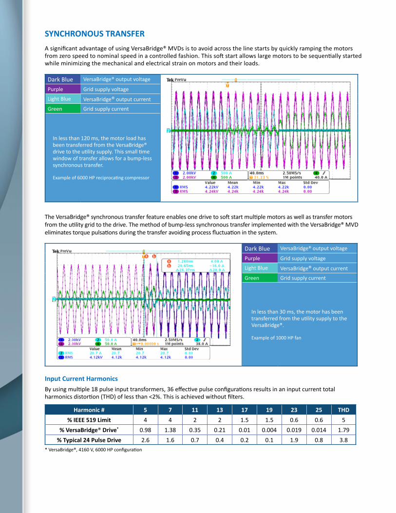
SYNCHRONOUS TRANSFERA significant advantage of using VersaBridge® MVDs is to avoid across the line starts by quickly ramping the motors from zero speed to nominal speed in a controlled fashion. This soft start allows large motors to be sequentially started while minimizing the mechanical and electrical strain on motors and their loads.
Dark Blue VersaBridge® output voltage
Purple Grid supply voltage
Light Blue VersaBridge® output current
Green Grid supply current
In less than 120 ms, the motor load has been transferred from the VersaBridge® drive to the utility supply. This small time window of transfer allows for a bump-less synchronous transfer.
Example of 6000 HP reciprocating compressor
The VersaBridge® synchronous transfer feature enables one drive to soft start multiple motors as well as transfer motors from the utility grid to the drive. The method of bump-less synchronous transfer implemented with the VersaBridge® MVD eliminates torque pulsations during the transfer avoiding process fluctuation in the system.
Dark Blue VersaBridge® output voltage
Purple Grid supply voltage
Light Blue VersaBridge® output current
Green Grid supply current
In less than 30 ms, the motor has been transferred from the utility supply to the VersaBridge®.
Example of 1000 HP fan
Input Current HarmonicsBy using multiple 18 pulse input transformers, 36 effective pulse configurations results in an input current total harmonics distortion (THD) of less than <2%. This is achieved without filters.
Harmonic # 5 7 11 13 17 19 23 25 THD% IEEE 519 Limit 4 4 2 2 1.5 1.5 0.6 0.6 5
% VersaBridge® Drive* 0.98 1.38 0.35 0.21 0.01 0.004 0.019 0.014 1.79% Typical 24 Pulse Drive 2.6 1.6 0.7 0.4 0.2 0.1 1.9 0.8 3.8
* VersaBridge®, 4160 V, 6000 HP configuration

LINE AND MOTOR CURRENT AND VOLTAGEThe VersaBridge® design provides near sinusoidal current and voltage. A combination of high PWM switching frequency and multi-level PWM output produces very low levels of electrically induced pulsating torques at the motor shaft.
Near sinusoidal input and output currents minimize site installation issues by allowing the VersaBridge® drive to be located further away from the motor installation.
Testing can be done at the TECO-Westinghouse facility in Texas with VersaBridge® MVD units. The motors and VersaBridge® MVDs shown in the image below were manufactured at this location and demonstrated that motor temperature rise at full load (measured by RTDs) is only 1°C higher when compared to across the line operation.

SPECIFICATIONS
ElectricalOutput Voltage 0 – 13.8 kVOutput Frequency (Min - Max) 0 – 120 Hz Auxiliary Supply 200 - 240 V, 1 φ std; optional configuration availableRated Supply Voltage 2.3 – 13.8 kV ± 10%Rated System Frequency 60 Hz ± 5%Voltage Variation -30% to +10% for 30 line cyclesInput Current Harmonics THD ≤ 2% Exceeds IEEE-519 requirementsInverter Topology H-BridgeCapacitors FilmRegulatory Compliance IEEE, ANSI, NEMA, UL, cULControls V/Hz, Sensorless vector Speed Regulation 0.1% with feedback, 0.5% without feedbackConnection Top, bottom or both cable entry/exitPower Ride Through Minimum 5 cyclesNominal Efficiency 97% Input Power Factor ≥ 96%Output Current Harmonics THD < 1%Power Transformer Topology ModularPower Transformer Rating 750 kVA/ SliceSpinning Load Catch a spinning loadAuto-Cube Bypass Automatic and manual Synchronous Transfer Automatically transfer the motor to/from the utility linePower Section Isolation Fiber optic cableService Duty CT: 150% , VT: 110% for 1 min every 10 minDisplay 7" TFT color LCD screen, LED backlightingCommunication Interface Modbus TCP/IP (Ethernet), RS-232 , and RS-485, PLC I/O,
others available upon request
MechanicalStandard Rating NEMA 1, NEMA 3RCabinet Dimension (Mains or Slice) H: 105 in (+1 in, lifting) x W: 25 in x D: 68.4 inMaterial ASTM A366Color WhiteTotal Weight Mains: 1289 lbs, Slice: 4852 lbs
Environmental ConditionAmbient Temperature -20 to +40°C (lower/ higher temperature*)Altitude 0 to 3300 ft (higher elevation*)Humidity 95%, non-condensingNoise Level ≤ 78 dB
Cooling SystemTransformer Choice of forced air-cooled or two phase cooling (R134a)Electronics Two phase cooling (R134a)
* Consult factory for additional options.
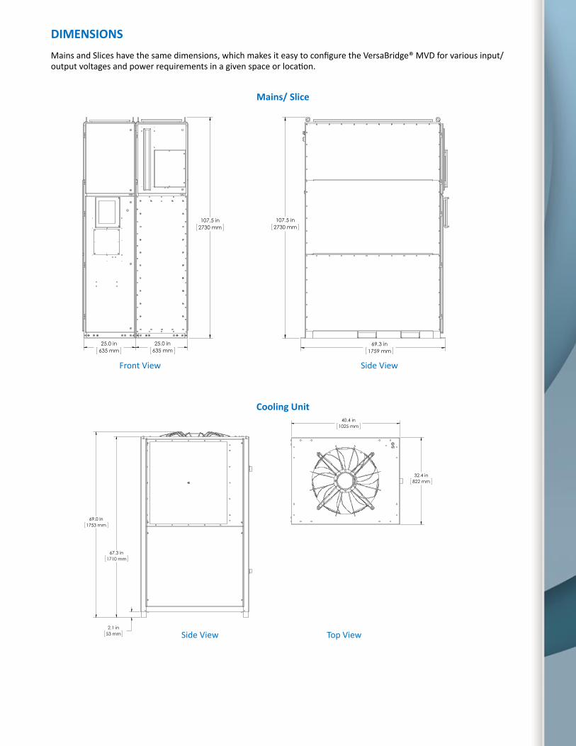
Mains/ Slice
Front View Side View
Cooling Unit
DIMENSIONSMains and Slices have the same dimensions, which makes it easy to configure the VersaBridge® MVD for various input/output voltages and power requirements in a given space or location.
25.0 in635 mm
25.0 in635 mm
107.5 in2730 mm
69.3 in1759 mm
107.5 in2730 mm
32.4 in822 mm
40.4 in1025 mm
69.0 in1753 mm
67.3 in1710 mm
2.1 in53 mm
32.4 in822 mm
40.4 in1025 mm
69.0 in1753 mm
67.3 in1710 mm
2.1 in53 mm
Side View Top View
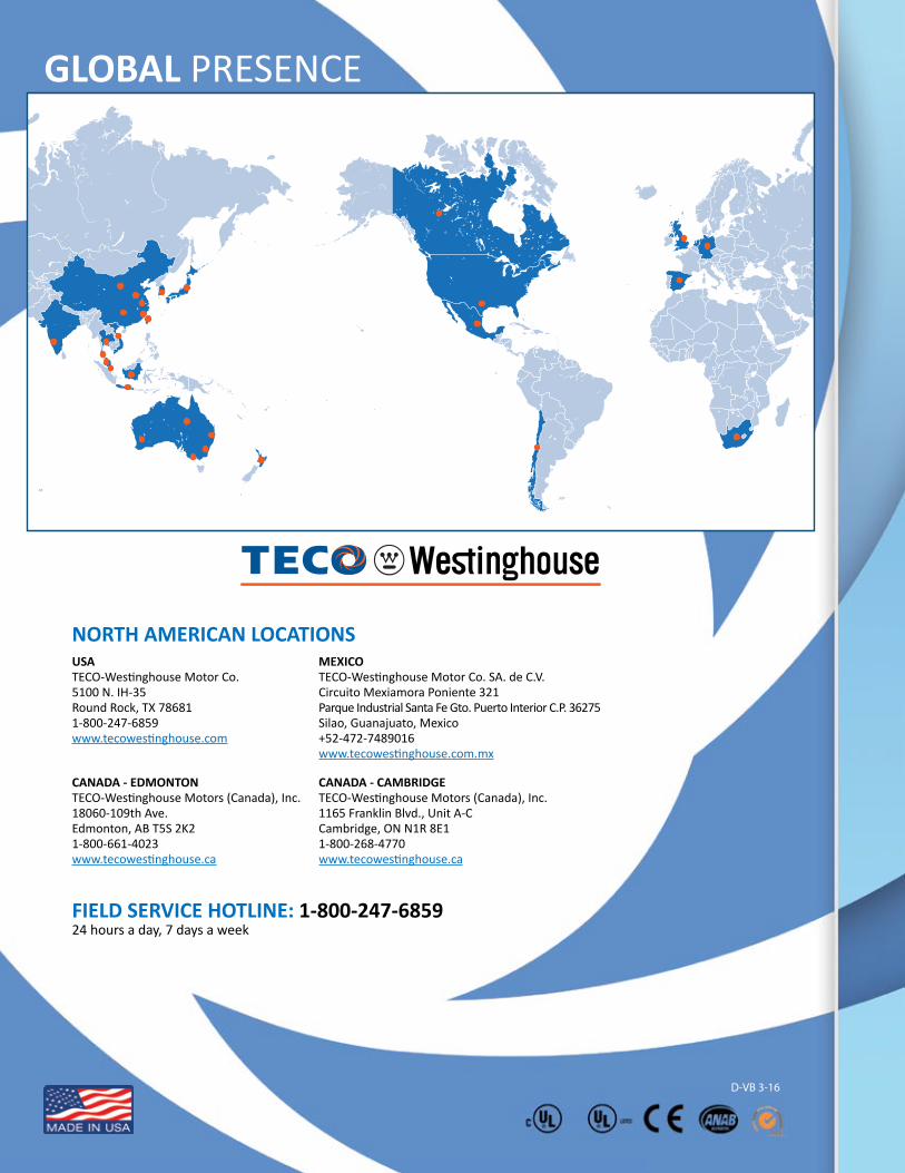
FIELD SERVICE HOTLINE: 1-800-247-685924 hours a day, 7 days a week
GLOBAL PRESENCE
USATECO-Westinghouse Motor Co.5100 N. IH-35Round Rock, TX 786811-800-247-6859www.tecowestinghouse.com
NORTH AMERICAN LOCATIONS
CANADA - EDMONTONTECO-Westinghouse Motors (Canada), Inc.18060-109th Ave.Edmonton, AB T5S 2K21-800-661-4023www.tecowestinghouse.ca
CANADA - CAMBRIDGETECO-Westinghouse Motors (Canada), Inc.1165 Franklin Blvd., Unit A-CCambridge, ON N1R 8E11-800-268-4770www.tecowestinghouse.ca
MEXICOTECO-Westinghouse Motor Co. SA. de C.V.Circuito Mexiamora Poniente 321Parque Industrial Santa Fe Gto. Puerto Interior C.P. 36275Silao, Guanajuato, Mexico+52-472-7489016www.tecowestinghouse.com.mx
D-VB 3-16