
Patent Application of Vitit Kantabutra for TITLE ...kantviti/Kantabutra-ILE-Patent.pdf · Patent...
22
Patent Application of Vitit Kantabutra for TITLE: INTENTIONALLY-LINKED ENTITIES: A GENERAL-PURPOSE DATABASE SYSTEM CROSS-REFERENCE TO RELATED APPLICATIONS This application claims the benefit of provisional patent application Ser. No. 61/075,189, filed 2008 June 24 by the present inventor. OTHER RELEVANT APPLICATIONS • Patent no. 7,483,920 Jan 27 2009 Mori, et al.: Database management system, database management method, and program • Patent no. 7,333,986 Feb 19 2008 Minamino, et al.: Hierarchical database manage- ment system, hierarchical database management method, and hierarchical database management program • Patent no. 6,633,886 October 14, 2003 Chong: Method of implementing an acyclic directed graph structure using a relational database 1
Transcript of Patent Application of Vitit Kantabutra for TITLE ...kantviti/Kantabutra-ILE-Patent.pdf · Patent...

Patent Application of Vitit Kantabutra for
TITLE: INTENTIONALLY-LINKED ENTITIES: A
GENERAL-PURPOSE DATABASE SYSTEM
CROSS-REFERENCE TO RELATED APPLICATIONS
This application claims the benefit of provisional patent application Ser. No. 61/075,189,
filed 2008 June 24 by the present inventor.
OTHER RELEVANT APPLICATIONS
• Patent no. 7,483,920 Jan 27 2009 Mori, et al.: Database management system, database
management method, and program
• Patent no. 7,333,986 Feb 19 2008 Minamino, et al.: Hierarchical database manage-
ment system, hierarchical database management method, and hierarchical database
management program
• Patent no. 6,633,886 October 14, 2003 Chong: Method of implementing an acyclic
directed graph structure using a relational database
1

OTHER REFERENCES
[1] C. J. Date and E. F. Codd, “The Relational and Network Approaches: Comparison of the
Application Programming Interfaces,” in ACM SIGFIDET (now SIGMOD) workshop
on Data description, access and control, 1974.
[2] J. D. Ullman, Principles of Database and Knowledge-Base Systems, Vol. 1, Computer
Science Press, 1988.
[3] H. F. Korth and A. Silberschatz, Database System Concepts, second edition, McGraw-
Hill, 1991.
[4] H. Garcia-Molina, J. D. Ullman, and J. Widom, Database Systems: The Complete Book,
second edition, Prentice-Hall, 2009.
[5] University of Illinois, Urbana-Champaign database tutorial found at
http://mias.uiuc.edu/files/tutorials/kcchang01.ppt
[6] Introductory information on database management systems at
http://www.scribd.com/doc/14355522/dbms
FEDERALLY SPONSORED RESEARCH
Not applicable.
BACKGROUND – FIELD OF THE INVENTION
This application relates to database systems, specifically to database systems in which there
are data entities that have relationships amongst one another.
2

BACKGROUND – PRIOR ART
All but the most trivial databases comprise data entities of various sorts and interrelation-
ships among them. For example, databases of social or political networks, technical sys-
tems, movie production networks, university information, and virtually all other non-trivial
database systems involve entities and their interrelationships. Naıve users might store in-
formation in text files or spreadsheets. More sophisticated users might turn to Relational
database systems. Heretofore the best known ways to store databases involving entities
and their interrelationships are, (1) Relational Databases, (2) Object-Oriented Databases,
including variations like Object-Relational Databases, (3) XML, and (4) Hierarchical and
Network Databases, these last types considered mostly obsolete. None of these is really sat-
isfactory for storing data about systems of any complexity in terms of the interrelationships
amongst data entities. Relational Databases have a high level of built-in data redundancy
that invites errors and inconsistencies. These shortcomings can make the design of a good
database schema difficult, and can even make the simple act of data entry very annoying.
Object-Oriented databases and the like only directly support simple relationships and can
be hard to use, accounting for their lack of popularity. XML imposes an hierarchy on the en-
tities, and only allows limited breakaway from the hierarchy with any degree of convenience.
Additionally, pointers indicating the non-hierarchical relationships are represented as text
rather than true pointers.
Like XML, Hierarchical databases are oriented towards hierarchical relationships amongst
data entities rather than more general relationships.
Network databases permit non-hierarchical relationships more natively, but are still hard
to use because it is oriented towards binary, many-to-one relationships, requiring more gen-
eral relationships to be available only by simulation. Additionally, querying a Network
database is an exercise in “manual” (programmed) physical navigation of the network, which
means that any update to the database requires code update as well. The query language is
procedural rather than declarative like SQL.
We need to spend more attention to Relational and Network databases in our discussion
3

of prior art. Relational databases need to be examined in more detail because it is still
the predominant type of database, and hence is so readily available that it is used even in
inappropriate circumstances. Network databases, on the other hand, needs to be examined
in detail because it is the closest to what we are proposing to patent here, though also
significantly different as we will point out.
The Relational database scheme certainly has the advantage of simplicity over all the
others except for the flat file database, which is not discussed here. As Codd, its inventor,
stated, the only concept the user really has to know to begin using Relational databases
is that of a two-dimensional table. Every data entity is represented merely by something
that can be written into one or more table entries, such as a character string (a name,
perhaps) or a number (I.D.), or a combination of a string and a number, for example. Often,
such simplicity works very well in practice. However, real-world databases get complex very
quickly, and often such simplicity doesn’t work any more, as we will now see through a real
example.
Our sample application is to store a database about a network of merchants and their
clients in Mediaeval Spain. The source of our data is a set of notarized documents or
contracts, each representing some kind of business transaction from the 1500’s. In each
business transaction, there was one or more merchants acting as servers or service providers
and zero or more clients. In case there is exactly one server and one client, the transaction
is easily represented as a row in a Relational database. However, even in this case there is a
potential for errors due to mistyping. For instance, if each person’s name (or an ID number)
is used as a key, and it is misspelled or mistyped. Such an act of misspelling or mistyping
amounts to the creation of a new person entity. This is an important flaw in Relational
databases - it is caused by the fact that something as important as an entity (a person, no
less!) is represented by a mere character string (or an ID number).
Another problem arises when we try to use a Relational database if the numbers of servers
and clients can vary, as they do in the actual application under consideration. Relational
database tables can’t have a variable number of columns. One solution is to have enough
4
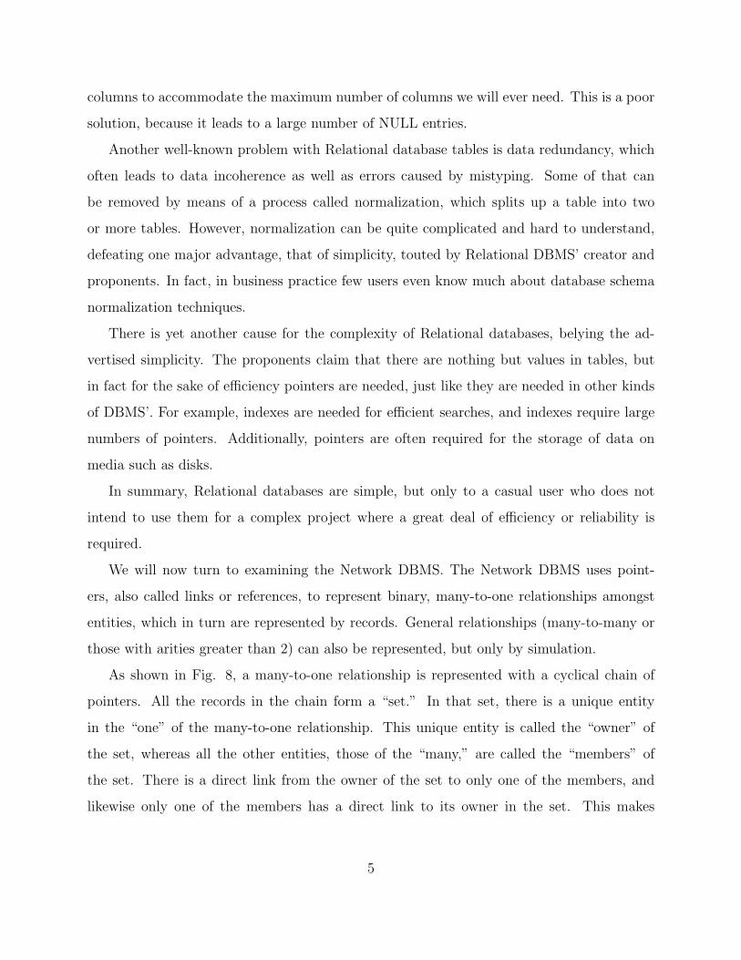
columns to accommodate the maximum number of columns we will ever need. This is a poor
solution, because it leads to a large number of NULL entries.
Another well-known problem with Relational database tables is data redundancy, which
often leads to data incoherence as well as errors caused by mistyping. Some of that can
be removed by means of a process called normalization, which splits up a table into two
or more tables. However, normalization can be quite complicated and hard to understand,
defeating one major advantage, that of simplicity, touted by Relational DBMS’ creator and
proponents. In fact, in business practice few users even know much about database schema
normalization techniques.
There is yet another cause for the complexity of Relational databases, belying the ad-
vertised simplicity. The proponents claim that there are nothing but values in tables, but
in fact for the sake of efficiency pointers are needed, just like they are needed in other kinds
of DBMS’. For example, indexes are needed for efficient searches, and indexes require large
numbers of pointers. Additionally, pointers are often required for the storage of data on
media such as disks.
In summary, Relational databases are simple, but only to a casual user who does not
intend to use them for a complex project where a great deal of efficiency or reliability is
required.
We will now turn to examining the Network DBMS. The Network DBMS uses point-
ers, also called links or references, to represent binary, many-to-one relationships amongst
entities, which in turn are represented by records. General relationships (many-to-many or
those with arities greater than 2) can also be represented, but only by simulation.
As shown in Fig. 8, a many-to-one relationship is represented with a cyclical chain of
pointers. All the records in the chain form a “set.” In that set, there is a unique entity
in the “one” of the many-to-one relationship. This unique entity is called the “owner” of
the set, whereas all the other entities, those of the “many,” are called the “members” of
the set. There is a direct link from the owner of the set to only one of the members, and
likewise only one of the members has a direct link to its owner in the set. This makes
5

for inefficient searches. Note, though, that proponents of Network databases thought that
Network databases are often more efficient than Relational databases because of the links
in the former. But the links in Networks DBMS’s can be quite indirect, which means that
searches in ILE, with its links being more direct, should be generally more efficient than in
either of the other two types of databases.
Searches in a Network database is done by means of pointer navigation or traversal. Such
navigation is done by procedural, not declarative, code, and must be explicitly programmed
by the application programmer. This is not only difficult because the application programmer
has to know the exact structure of the database, but it also means that any change in the
database could be bad news, because it frequently requires code change!
Additionally, even simple queries may require traversing practically the entire network of
records [6]. There is no automatic, easy-to-use search facility in Network databases.
DRAWINGS – Figures
• Fig. 1 shows an embodiment of an entire Intentionally-Linked Entities (ILE) Database
system.
• Fig. 2 shows a data structure or object representing an ILE database according to an
embodiment.
• Fig. 3 shows a data structure or object representing an entity set in an ILE database
according to an embodiment.
• Fig. 4 shows a data structure or object representing an entity in an ILE database
according to an embodiment.
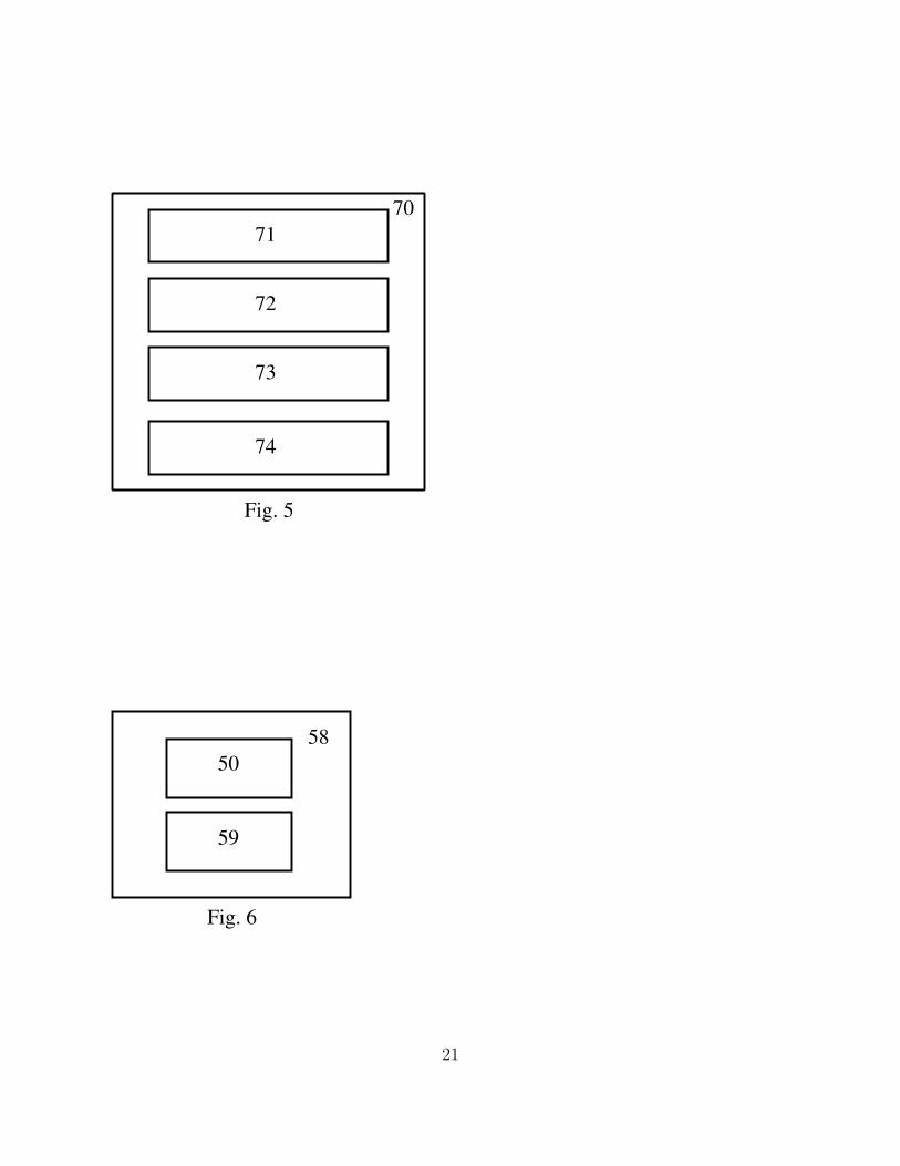
• Fig. 5 shows a data structure or object representing a relationship set in an ILE
database.
• Fig. 6 shows a data structure or object representing an “entity set plus” (ESP). An
ESP data structure or object comprises the entity set as well as the names and types
6

of per-relationship attributes of the entities in the entity set.
• Fig. 7 shows a relationship data structure or object, as represented in an embodiment
as an array of arrays of elements, where each element is a reference to an ESP object
shown in the previous figure.
• Fig. 8 (prior art) shows how a many-to-one relationship between entities is defined in a
Network database. In a Network database, only many-to-one, binary relationships are
implemented directly without simulation. Such a relationship is implemented with a
circular linked list as shown in this figure. There is no direct link from the “Harrison”
student record to the “MA235” enrollment record. Note that many real databases have
many-to-one and/or non-binary relationships, making Network databases hard to use.
Even this example here, which is similar to one from a written source, is unrealistic as
it stands because only one student can be enrolled in each course! (Note that in fact,
direct implementation of a relationship is only permitted if the “many” and the “one”
records are of different types. That is, even a many-to-one, binary relationship must
be simulated if the records of the “many” and the “one” are of the same type. This
helps to make Network databases difficult to program.)
DRAWINGS – Reference Numerals
• 10 Set of all database sets.
• 20, 20’ Database sets.
• 30, 30’ Databases.
• 31 Database name (or a reference thereto)
• 32 A data structure of entity sets or a reference thereto. In an embodiment, such a
structure is a hash of entity set references. The entity set name is used as the hash
key to aid searches.
7

• 33 A data structure of relationship sets or a reference thereto. In an embodiment,
such a structure is a hash of relationship set references. The relationship set name is
used as the hash key to aid searches.
• 34 An optional data structure that may be used to store any useful information
pertaining to the database.
• 40 Set of all the entity sets in the database.
• 50, 50’ Entity sets.
• 51 Entity set name or a reference thereto.
• 52 A reference to the database this entity set belongs to.
• 53 An ordered data structure (can be embodied as a dynamically-allocated array)
representing all the names (and optionally types) of key attributes. Note that in ILE,
there are no hidden key implied by the storage location of an object as there was in
Network databases. In this sense ILE is “value-oriented” rather than “object-oriented.”
• 54 An ordered data structure (can be embodied as a dynamically-allocated array)
representing all the names (and optionally types) of non-key attributes.
• 55 A data structure or object containing all the entities belonging to this entity set,
or a reference to such a data structure or object.
• 56 References to all the relationship sets containing the relationships in which the
entities belonging to this entity set are involved.
• 57 Optional data structure that may be used to store any useful information pertaining
to the entity set.
• 58 “Entity Set Plus,” comprising an entity set data structure object as well as a
data structure or object representing the names and types of attributes that pertain
8
to both the entity and the relationship, also called the ”per-relationship attributes” of
an entity.
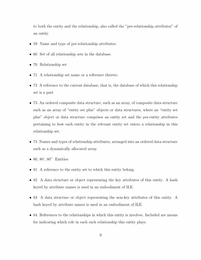
• 59 Name and type of per-relationship attributes.
• 60 Set of all relationship sets in the database.
• 70 Relationship set
• 71 A relationship set name or a reference thereto.
• 72 A reference to the current database, that is, the database of which this relationship
set is a part
• 73 An ordered composite data structure, such as an array, of composite data structure
such as an array of “entity set plus” objects or data structures, where an “entity set
plus” object or data structure comprises an entity set and the per-entity attributes
pertaining to how each entity in the relevant entity set enters a relationship in this
relationship set.
• 74 Names and types of relationship attributes, arranged into an ordered data structure
such as a dynamically allocated array.
• 80, 80’, 80” Entities
• 81 A reference to the entity set to which this entity belong.
• 82 A data structure or object representing the key attributes of this entity. A hash
keyed by attribute names is used in an embodiment of ILE.
• 83 A data structure or object representing the non-key attributes of this entity. A
hash keyed by attribute names is used in an embodiment of ILE.
• 84 References to the relationships in which this entity is involves. Included are means
for indicating which role in each such relationship this entity plays.
9

• 88 “entity plus,” comprising an entity data structure or object plus attributes per-
taining to this entity as it enters into a particular relationship. These attributes are
determined by both the particular entity and the particular relationship.
• 90, 90’ Relationships.
• 95 An element of an array of arrays in a relationship data structure or object according
to one embodiment. This element contains a reference to an “entity-set plus” (ESP)
object which is described above.
• 100 A student record in a Network database.
• 110, 110’ Enrollment records in a Network database.
• R0, R5, R0’ array elements containing pointers to entities playing roles 0 and 5,
respectively.
DETAILED DESCRIPTION
The subject of this patent is a new kind of database management system called Intentionally-
Linked Entities, or ILE. In ILE, relationships among entities will be represented directly as
true links among them. Thus general graphs (as in Graph Theory), and in fact more (to
be explained below), can be represented naturally. The data model will be similar to the
Entity/Relationship data model, which was never implemented very well in the prior art
partly due to the lack of good programming tools such as object-oriented languages and
simple-to-use dynamic memory allocation. (The most valiant attempt in the past was the
flopped Network Databases discussed earlier in this document.) However, at the present
time sufficient tools and programming languages have been developed so that complex linked
data structures are now in more widespread use. Complex linked data structures are used in
operating system kernels, for example. Interestingly enough, complex linked data structures
have not been used in the database field except in index structures. The main idea behind
the ILE database system is to use modern linked data structures, dynamically-allocated
10

arrays, hashes, and objects in general in the main arena of database storage to the fullest
extent possible.
What was meant above by saying that we can represent more than just general graphs
in ILE? In a graph, an edge represents a binary relationship, that is, a relationship between
two nodes, where the nodes commonly represent entities. In ILE, relationships with arities
greater than two are possible, and in fact are convenient to create and naturally represented.
Thus ILE data structures are more powerful than general graphs. In fact, in ILE, we can
also store a new kind of attribute that pertain not to entities in a static way, but that
pertain to the entities as they enter a specific relationship. These extra capabilities of ILE
are important in the application of ILE to complex networks such as the ones to be referred
to in the next paragraph.
We now turn to a more detailed description of ILE, as shown in Fig. 1. Reference 10
is an entire ILE system, which can contain an arbitrary number of databases. The idea is
that in ILE, we can enable the various databases in the system to communicate (share data)
with each other. The system is divided into database sets, references 20 and 20’, with the
idea that it is possible to permit databases in the same set to communicate with each other,
but that we could optionally disallow communications across different sets. In fact a more
complex tree of databases may prove useful, but that is off topic for this patent. In each
database set, say reference 20’, there can be an arbitrary number of databases. In Fig. 1,
references 30 and 30’ are two databases in the same database set 20’. From now on we will
just concentrate on one database, say reference 30’.
A database includes a data structure or object such as a hash that contains or holds
references to all the entity sets (reference 40), which are data structures or objects that
represents sets of data entities, such that all the entities in each such set are of the same
kind. For example, in a university database all entities representing students could be in a
single entity set.
A database also includes a data structure or object that contains or hold references to
all the relationship sets (reference 60), which are data structures or objects that represent
11

sets of relationships of like kind. For example, all the relationships between two people of
the form ”is the father of” form one relationship set.
Fig. 2 shows the contents of a database object in more detail. The data structures of
entity set and of relationship sets mentioned in the previous two paragraphs are shown as
references 32 and 33 in Fig. 2. Ref. 31 is the database name or a reference thereto. Ref. 34
is optional information (or a link thereto), such as notes about the database.
Now we look into an embodiment of a data structure or object that holds an entity set,
which is shown as references 50 and 50’ in Fig. 1. Referring to Fig. 3. Ref. 51 is the name
of the entity set, or a reference thereto. Ref. 52 is a reference to the database to which this
entity set belong. This is not necessary, but can make some operations more convenient.
Ref. 53 is an ordered data structure (such as an array, dynamically allocated) of the key
attribute names and types.
Much as ILE uses modern objects for its implementation, and is object-oriented in the
sense that it can be embodied to permit objects as data entities, it is not an object-oriented
database like Network databases, as in the sense used in Ullman [2] but is instead value-
oriented like Relational databases. That is, ILE does not use storage location as key, but
uses key attribute values as key instead.
Back to Fig. 1, Ref. 60 is a data structure that holds (a reference to) all the relationship
sets in the current ILE database. Ref. 70 and 70’ are sample relationship sets. Fig 5 shows
a relationship set as implemented in an embodiment. Ref. 71 is the relationship set name
or a reference thereto. Ref. 72 is a reference to the current database. Ref. 73 is an ordered
composite data structure, such as an array, of composite data structure such as an array
of “entity set plus” objects or data structures, where an “entity set plus” object or data
structure comprises an entity set and the per-entity attributes pertaining to how each entity
in the relevant entity set enters a relationship in this relationship set. Ref. 74 contains
names and types of relationship attributes, arranged into an ordered data structure such as
a dynamically allocated array.
Describing now samples of individual entities, we once again refer to Fig. 1. References 80,
12

80’, and 80” are entity objects or data structure. Fig. 4 shows the details of an embodiment
of an entity as a data structure or object. Ref, 81 is a reference to the entity set to which
this entity belongs. Ref. 82 is a data structure or object representing the key attributes of
this entity, whereas ref. 83 represents the non-key attributes. Ref. 84 are references to the
relationships in which this entity is involves. Included are means for indicating which role
in each such relationship this entity plays.
Ref. 90, 90’ in Fig. 1 are relationship objects or data structures. Fig 7 details a relation-
ship data structure or object. A relationship, in one embodiment, is represented by an array
of array (all arrays are dynamically allocated). Each element of this array is represented
as reference 95, and is actually called an “Entity-Plus” object, shown as references 88, 88’,
88”’ and 88”’ in Fig. 1. An Entity-Plus data structure or object comprises an entity data
structure or object plus attributes pertaining to this entity as it enters into a particular re-
lationship. These attributes are determined by both the particular entity and the particular
relationship.
A simpler embodiment of relationship objects is possible, wherein at most one entity
plays each role. Instead of having an entire array of “entity plus” objects representing each
role, we use only one such object. This simpler embodiment will be represented as a separate
set of claims.
Finally note that the database is value-oriented, as opposed to object-oriented, in the
sense that the address of an entity is not part of the key, thus permitting value-comparison-
based searches. To understand this last point it is important to note that there was a different
meaning to the phrase “object-oriented” than the one currently used. See Ullman [2] in the
“Other references” section. There, a database is object-oriented if the storage location
of an entity can be used as the entity’s key. The opposite of object-oriented is “value-
oriented.” A database is value-oriented if an entity is identified only by attribute values.
Relational databases are value-oriented, and its success relative to Network databases is
due in a significant part to that fact. Learning from that success, ILE is meant to be
value-oriented. It can be said that ILE has Relational DBMS’s advantage of being value-
13

orientedness, as well as Network DBMS’s advantage of having links, although ILE’s links are
more direct than those of Network DBMS’s.
14
CLAIMS
I claim:
1. A method for storing a database involving data entities and relationships of any finite
arity amongst said entities, comprising:
a. storing each said entity in a data structure, which could be an object, henceforth
referred to as an entity object,
b. storing each said relationship amongst entities in a data structure, which could be
an object, henceforth referred to as a relationship object,
c. for each said relationship, grouping zero, one, or more said entities that serve in each
role of said relationship into a composite data structure such as a dynamically-
allocated array,
d. linking with pointers or references each said relationship object with the appropriate
members of said composite of entities involved in the relationship represented by
said relationship object,
e. providing users or client programs with convenient and direct means of creating
said entity objects and relationship objects without having to simulate or create
said objects from other types of records.
2. The method of Claim 1 wherein said entities of like kind are grouped together into
entity sets, and said relationships of like kind are grouped together into relationship
sets.
3. The method of Claim 2 wherein, in each said entity, there exist links between the entity
and all the relationships in which said entity is involved, and associated with each said
link is a means by which the entity’s role in the relationship can be identified.
4. The method of Claim 3 wherein said means of role identification is implemented as
a hash of hashes of dynamically-allocated arrays, where each hash element at the
15

outer level represents links from said entity set to the relations in any one particular
relationship set whose name would be the hash key.
5. The method of Claim 4 wherein each hash element at the inner level represents a
particular role played by said entity, and the role index would serve as the hash key.
6. The method of Claim 5 wherein each array element represents one relationship, and in
one embodiment these relationships are not sorted in any particular order in the array.
7. The method of Claim 1 wherein a query language is provided as means for find (search)
operations taking attributes and entity sets as parameters, such that it is not necessary
to traverse the entire database or traverse entities in irrelevant entity sets to answer
queries.
8. A method for storing a database involving data entities and relationships of any finite
arity amongst said entities, comprising:
a. storing each said entity in a data structure or an object, henceforth referred to as
an entity object,
b. storing each said relationship amongst entities in a data structure or an object,
henceforth referred to as a relationship object,
c. linking with pointers or references in both directions each said relationship object
with the entities involved in the relationship represented by said relationship
object,
d. providing users or client programs with convenient and direct means of creating
said entity objects and relationship objects without having to simulate or create
said objects from other types of records.
9. The method of Claim 8 wherein said entities of like kind are grouped together into
entity sets, and said relationships of like kind are grouped together into relationship
sets.
16

10. The method of Claim 9 wherein, in each said entity, there exist links between the entity
and all the relationships in which said entity is involved, and associated with each said
link is a means by which the entity’s role in the relationship can be identified.
11. The method of Claim 8 wherein a query language is provided as means for find (search)
operations taking attributes and entity sets as parameters, such that it is not necessary
to traverse the entire database or traverse entities in irrelevant entity sets to answer
queries.
ABSTRACT
In accordance with one embodiment the subject of the patent is a method for storing a
database comprising entity objects or data structures representing the data entities, and
relationship objects or data structures representing the relationships amongst the entities.
Each relationship object or data structure possesses links to the entity objects or data struc-
tures that play the various roles in the relationship. Where there is a link from a relationship
to an entity, there is also a link from the entity to the relationship, facilitating queries and
updates to the database system. It is possible and often desirable for an embodiment to per-
mit not merely one, but possibly many (or zero) entities to play each role in a relationship.
The database is value-oriented in the sense that the address of an entity is not part of the
key, thus permitting value-comparison-based searches.
17

88’
R0
R5
90
90’
R0’
20 20’
30
4050
50’
7060
80
80’’
88
80’
30’
10
Fig. 1
70’
88’’’
88’’
18

Fig. 2
31
30
32
33
34
19

50
51
53
52
54
55
56
57
Fig. 3
80
82
81
83
84
Fig. 4
20
70
71
72
73
74
Fig. 5
59
50
58
Fig. 6
21

95
Fig. 7
Fig. 8
Harrison CS252
MA235
A
B+
110
110’
100
22