
PAT4E Appliance Tester - · PDF fileRepair and Warranty 55 Symbols used on the instrument....
57
M PAT4E Appliance Tester User Guide MEGGER ®
Transcript of PAT4E Appliance Tester - · PDF fileRepair and Warranty 55 Symbols used on the instrument....

M PAT4E Appliance Tester User Guide MEGGER ®

Contents
2
Safety Warnings 3 General Description 4 Features and Controls 5 Quick-start Guide 6 Settings 12
Contrast Adjustment 12 Reset to default Settings 12 Short cut to Comms Upload (from PC) 12 Language of operation 12 Test results printout 12 Function Setting adjustment 13 User name and Pin number 13 Setup Manual/Autopass testing 14 Setup Buzzer 14 Setup Test Times 15 Setup Clock 17 Setup Test Company Title 18
Client and Locations 19 Select an existing Client and Location 19 Select a new Client and Location 19 Edit Client/Location details 21 Erase Client details 21 Erase Location details 22 Add new Client, main address, site location 22 Add new site Location details 23 Asset Test Groups 25 Table of test group combinations 26 Add new Group 27 Edit a Group 27 Erase a Group 28
Assets 31 Add Asset 31 Edit Asset 33 Erase Asset 33 Locate an Asset 35
Testing Asset 37 Automated Testing 37 Quick-Check 39 Repair codes 40 Erase Memory 41
Communications 42 Print Report 42 Download / Upload data 44 Serial lead connections 44 Download to a computer 44 Upload from a computer 44
Description of tests 45 Visual Inspection Test 45 RISO Insulation Test 45 RPE Earth Continuity Test 45 Operation Test 46 IDIFF Differential Earth Leakage Test 46 IPE Substitute Discharge Leakage Test 46 IF Absence of Potential Leakage Test 46 Fuse Test 46 Extension Lead Testing 46
Three Phase Testing Typical Configurations 47 Demonstration Data 48 Specifications 52 Accessories 54 Repair and Warranty 55 Symbols used on the instrument. Caution: Refer to accompanying notes Risk of electric shock.
Equipment complies with relevant EU Directives

Safety.
3
SAFETY WARNINGS
• Safety Warnings and Precautions must be read and understood before the instrument is used. They must be
observed during use. • For safety, PAT4E must be properly earthed. Only use a supply socket that has a protective earth contact. • Test leads, probes and crocodile clips must be in good order, clean and with no broken or cracked insulation. • For safety, tests are performed in the correct order. If an asset (appliance) fails a test, PAT4E will fail the
asset and exit the test sequence. The fault causing the failure must be corrected before the appliance is re-tested.
• During testing, ensure that no hazard will exist if the asset operates as a result of normal running, or of a fault
condition.
• When performing an Insulation test the asset must not be touched. • Only perform an Operation test after an RPE Test (Class 1 only) and Insulation RISO Test (Class 1 or Class 2)
have been verified. • The instrument should not be used if any part of it is damaged. • Replacement fuses must be of the correct type and rating. See 'Specification' section.
NOTE: THE INSTRUMENT MUST ONLY BE USED BY SUITABLY TRAINED AND COMPETENT PERSON

General Description.
4
The PAT4E Portable Appliance Testers provide significant advances in the ease of use, with comprehensive features designed to speed up the testing of electrical equipment. The instruments meets the testing requirements of the UK Electricity at Work Regulations, IEE Code of Practice for In Service Inspection and Testing of Electrical Equipment, VDE 0701 and NEN 3140 specifications. The instruments may be used stand alone, or for maximum advantage, with PC based software, such as Form Filler T M for Windows T M (See Accessories). The integral real time clock “stamps” an accurate time and date on every test. PAT4E utilise a unique concept known as Test Groups. This permits very rapid addition and testing of equipment with a minimum of data entry. Once set up, the use of Test Groups will save a great deal of time. Additionally, Test Groups ensure that only the correct tests can be applied to the equipment under test and eliminate the need for complex test codes. PAT4E provides a professional system for the rapid testing of equipment while maintaining the essential traceability of asset test history. The on-board Asset (Appliance) database keeps a record of appliance details, re-test frequency, test and re-test dates, and allows the previous test results to be displayed at the time of test. As well as the easy to use QWERTY keyboard, each field is named, so there is less chance of entering the wrong information. Data entry via optional bar code scanners is also possible. The lithium backed ‘real time’ clock maintains the time and date accurately for over ten years and automatically date and time stamps every asset tested. Data is stored in battery backed, solid state memory that under normal circumstances will be protected for ten years. Such storage media is however susceptible to external influences such as transients and static discharge. These effects may cause data corruption or loss.
Megger Limited cannot accept responsibility for any such losses of data. When the PAT4E is used with PC software such as Form Filler T M, employing good working practices, such as the regular downloading of data will substantially reduce the risk. The following information can be stored and accessed directly on the PAT4E. • Assets (Appliances) - total number 1000 • Results (sets of) 1000 • Clients (names and addresses) 10 • Locations (Site details) 20 • Test Groups 50 • Users 10 The instruments can perform the following tests: • Visual Inspection list • Fuse Test • Circuit test (pre-test) • Earth Continuity test (RPE) • Insulation test (RISO) • Operation Test. • Extension Lead testing. • Differential Earth Leakage Test. (IDIFF) • Touch Current Test (IF) • Equivalent Earth Leakage Test (IPE)

Features and Controls.
5
Mains power Connection
12.5 A Protection
Fuses
3 Phase Test Connections
Appliance Test Connections
Fuse Test
Points
Lead and Accessory
Storage
Bar Code Scanner and PC
Connection
Parallel Printer
Connection
ESC / DEL key And Multi function
Soft key
OK key And Multi - function
Soft key
Space = Shift + 0
Extension Lead Test Connection
RPE Test Terminal
IF Test Terminal
Multi - function Soft keys
Display
FUSES - Due to the often harsh electrical environments in which Portable Appliance Testers are used and the likelihood of testing faulty equipment all Megger Portable Appliance Testers are protected by appropriate internal fuses. This ensures that the instrument is protected from serious damage. An unfortunate downside to using internal protection fuses is that the PAT4 can be rendered inoperative simply by the failure of such a fuse resulting in frustration and delay for the user. In order to ensure that the instrument can quickly be put back into service without downgrading its protection externally located fuses are now fitted to all new PAT4 models. These may be changed quickly and simply by the user in the event of a failure. For maximum convenience all fuses are of the same value. Additionally the PAT4 display will now indicate which fuse has failed, unless of course it is main supply fuse in which case the screen will be blank. Replacement of Fuses Always disconnect the PAT4 from the main supply before checking fuses. Use correct replacement fuses as printed adjacent to the fuse - Megger Part No. for replacement fuses 25950-014
FS2
FS1

Quick Start Guide.
6
This Quick Start guide is intended to show you how to select Clients and Locations and test appliances in the minimum of time. Other features may then be understood and investigated when convenient. In using this guide you will make use of the demonstration data that was loaded onto your instrument at the time of manufacture. Connecting to the Power supply Plug the PAT4E into a standard 230 V supply for testing. On connecting to the supply, the PAT4E performs a rapid self-test and calibration sequence. If the screen is dim, refer to “Contrast adjust”. Multi Function keys.
ESCape back to previous screen or used to DELete typed text. OK when there is no displayed function
Changing Languages. The PAT4E can be operated in one of four Languages. To select an alternative Language, the PAT4E must be powered up with the “L” key depressed until the language selection screen is displayed. Select from English, French, Dutch or German. Quick-Start demonstration In order to follow this Quick Start demonstration, you will need a 230V class 2 (Double insulated) asset (appliance) to test e.g. a hairdryer or a plastic cased power drill, but for the purpose of the Quick-start exercise it should be in a known, good condition. Logging in to the Unit PAT4E accepts up to ten User names / Pin numbers at any one time, allowing only authorised persons to use the unit, if required. To input User names and their respective pin numbers see ‘Settings’.
The Login screen is displayed, ready for the USER and PIN insertion.
User: PIN:
Login Screen
If you have not used the PAT4E before: 1. Type in the name AVO. Typing errors can be deleted using the
ESC/DEL key. Press the OK key. 2. Type in the Pin number 1234 and press the OK key. The
current Client will be briefly displayed followed by the “Client” screen.
Client SELECT
LOGOUT ACCEPT
Client Screen
Rather than ACCEPT the current client, we will demonstrate the different example Clients that have been loaded into your instrument. 3. Press the SELECT key. The Client Selection screen is
displayed.
NEXT Client MORE AVO INTERNATIONAL
Client Selection screen
This shows that the first client in the PAT4E database is called AVO INTERNATIONAL

Quick Start Guide (Continued).
7
4. Press the NEXT key repeatedly. Each time the key is pressed, the next Client is displayed. Three specimen clients are included in your demonstration data:
AVO International A.N. Other Client Yet Another Client
5. When the screen displays A.N. OTHER CLIENT, press the OK key . This selects A. N. Other Client as the one you are currently using. The Location‘ screen is now displayed.
Location SELECT
LOGOUT
Location screen
6. Press the SELECT key in order to view and choose the site
or building location. You will see that the first site location in the database for A. N. Other Client is called Ashford Site. PAT4E can hold up to twenty different Site locations.
7. Press the NEXT key repeatedly. Each time the key is pressed the next location within A. N. Other Client is displayed. Three such locations are included in your demonstration data:
Dover Site Folkestone Site Ashford Site
8. When the screen displays DOVER SITE, press the OK key. This selects Dover Site as the site location you are currently using. The Main screen is displayed.
TESTS QUICK-CHECK COMMS MENU Main screen
To summarise you have now selected
Client = A.N. Other Client Location = Dover Site
Auto Restart to Main screen The Client and Location need be selected only once for any particular site. PAT4E will assume the same settings until you deliberately logout from the Client. Even if mains power is removed e.g. when moving around a site, if you have not logged out, the PAT4E will automatically return to the Main screen. You are now ready to test appliances. Test appliances The use of test Groups, enables assets to be added to the PAT4E database, and select tests for the assets to be tested. PAT4E allows you to enter many details about the assets, or just an ID number and test Group. Once details are entered they remain with the appliance record, and never need to be re-entered, even when the appliance is re-tested at a later date. We recommend that full details of each appliance are entered the first time it is tested since this enhances traceability and gives full advantage of the features in Form Filler T M 9. With the Main screen displayed, press the TESTS key. The
Test screen is displayed.
ADD Test SEARCH SELECT
Test screen
Since your asset will not already exist in the PAT4E data you must first add it to the database. 10. Press the ADD key. Asset ID screen is displayed.

Quick Start Guide (Continued).
8
Asset ID �
Asset ID screen
You must now give the asset a unique reference number, which may be any combination of characters up to a maximum of ten. Since no appliances exist for the current location you may choose anything you like. e.g. 2468. 11. Type your chosen ID and press the OK key. The Group
screen is displayed.
LIST Group �
Group Screen
In order to test the asset (and other identical appliances) PAT4E needs to know what tests to apply and what Pass / Fail limits are acceptable. This is achieved by allocating a test Group to the asset (50 different test Groups may be created on your PAT4E each of which can be applied to any number of appliances). Ten examples are included in the demonstration data (see ‘Demonstration Data’). One such group created for typical Class 2 or double insulated equipment has been called TC2. 12. With the Group screen displayed, type TC2 and press the OK
key . The message “Group TC2 Accepted” is briefly displayed, followed by the display of:
Short cut to tests
TEST CONTINUE
You may press the CONTINUE key and enter full details for the asset. In this demonstration we will go straight to test the asset. 13. Press the TEST key. The Visual Inspection screen is shown
Visual Inspection FAIL PASS
Note: - Initially your PAT4E has been configured for Manual
operation. This means that whilst the tests applied to the appliance are governed by the chosen Group, PAT4E allows the user to decide whether each test result is a Pass or a Fail. This allows greater control over the testing, and for you to proceed one step at a time. It also provides display of the historic data stored on the PAT4E. Once familiar with the operation of the in PAT4E , you may choose to automate the test sequence to Pass or Fail each test according to the limits specified for the Group. This speeds up testing and is ideal where the operator may be unfamiliar with acceptable limits.
14. The first test specified for Group TC2 is the Visual inspection.
Carry out a full visual inspection of the asset and if acceptable press the PASS key. The next specified test is displayed. If unacceptable, press the FAIL key and PAT4E will pose a number of questions enabling you to specify the nature of the fault as follows:
Case OK? Plug OK? Mains Lead OK? On/Off Switch OK? Supply socket OK? Environment OK? e.g.operational hazards in the vicinity Suitability OK? e.g.used for correct purpose ? Everything Else OK?

Quick Start Guide (Continued).
9
Note: - If an asset fails a visual inspection, no further tests will be performed and a repair code may be entered (see “Repair Codes”). 15. Assuming that you have pressed PASS for the visual
inspection, PAT4E will prompt you to plug the asset into the tester. Press the YES key when this has been done.
PAT4E will conduct a pre-test to confirm that electrical continuity exists within the appliance i.e. that it has been switched On, and that any fuses are not ruptured. This is important otherwise the test results obtained will be meaningless. If the asset is very high resistance or very low resistance, PAT4E will warn you that the asset may accordingly be Open or Short circuit. You have the option to RETRY (forgotten to turn the asset on?) FAIL or IGNORE the warning. Note that some assets containing heating elements, filament lamps or very large motors may exhibit a very low resistance in their de-energised state, causing PAT4E to warn of a possible short circuit. In such cases, the warning can be ignored. Note: - If an Operation test is performed on a short circuit asset, PAT4E may be damaged. If in doubt DO NOT PROCEED. Press the FAIL key, suitably label, and remove the asset from service; investigate and rectify the fault, and re-test on completion. 16. PAT4E will proceed to the next test specified for group TC2
which is the Insulation test, and prompt you to connect the Insulation test lead (from the instrument IF terminal to any exposed metal or insulated part of the asset). Press the YES key when this has been done.
The insulation test will be applied for 5 seconds and the appropriate reading displayed. On completion of the test, PAT4E will display the result and allow you to PASS or FAIL the test.
Insulation Res.
FAIL >50MΩ *PASS
PAT4E automatically compares the result obtained with the limit specified in the group TC2 and places an asterisk * next to the appropriate PASS / FAIL key. In this case the lower limit specified in the group TC2 for an insulation test was 7 MΩ. Therefore a reading of >50 MΩ is a pass. Note: If the PAT4E had been setup in AUTOPASS mode it would have passed the test for you and proceeded to the next test in the sequence (see ‘Settings’). 17. Press the PASS key. PAT4E will proceed to the next test
(Leakage) specified for Group TC2. The following confirmation screen is displayed:
Asset will run SAFE?
For an Operation test or Differential Earth Leakage test, ensure that the asset is in a safe condition to run and that no hazards are present.
18. Confirm that it is safe for the asset to start and press the OK
key. To stop the test in emergency, press any key.
The asset will be operated for five seconds, during which time the differential earth leakage will be measured. (For test duration adjustment refer to “Settings”). On completion of the test, PAT4E perform a second differential leakage tests, as TC1 group contains

Quick Start Guide (Continued).
10
the reversible mains plug option enabled. The result will be displayed allowing you to PASS or FAIL the test.
Leakage test FAIL XX mA *PASS
19. Press the PASS key. PAT4E. The will perform an
operation test and show the test result
Operation test
FAIL XX VA *PASS
20. Press the *PASS key. This completes the test sequence
specified by the group TC2 so PAT4E will display whether the asset has passed or failed then prompt you for an optional repair code (see “Repair Codes”). In this instance, simply press the OK key.
21. Press the ESCape key to return to the Main screen. That
completes the testing of a single asset. The test results are now held against the asset record in the instrument and will be available for comparison next time you test the appliance.
Historical Data Demonstration. PAT4E incorporates a historic data facility that enables previous test results to be viewed at the time of testing. This powerful feature enables you to spot any dangerous degradation of the appliance since its last test. Whilst previous and current test results may each be considered acceptable in their own rights against the pre-defined limits, there are instances where two very different readings will indicate significant degradation of appliance safety. e.g.
Insulation test March 1998 = 50 MΩ Pass limit = 7 MΩ Insulation test March 1999 = 10 MΩ Pass limit = 7 MΩ Both readings are clearly a PASS, but if the degradation continued it would not be long before the asset insulation fell below the limit of 7 MΩ causing the appliance to fail the pre-set limits. To demonstrate the historical data facility we will simply re-test your Class 2 asset. Since the asset now exists in the PAT4E database you do not need to add it. From the Main screen, press the TESTS key to display the Test screen.
ADD Test SEARCH SELECT
Test screen
1. Press the SELECT key. The Asset ID screen is displayed.
Asset �
Asset ID screen 2. Now type your chosen asset ID (eg 2468) and press the OK
key. PAT4E will rapidly search its database, retrieve the appliance record, and display the update asset test screen. press the OK key.
Update Asset Data
NO YES

Quick Start Guide (Continued).
11
3. The date it was last tested will be displayed.
Last Tested
4. Press the OK key to continue and PAT4E will start the test sequence again. The Visual Inspection screen is displayed.
Visual Inspection
FAIL PASS
5. Press the PASS key for the visual inspection. PAT4E will
prompt you to plug the asset into the tester. 6. Press the YES key when this has been done to move on to
the Pre-test and Insulation tests. PAT4E will prompt you to connect the Insulation test lead (from the instrument to any exposed metal or insulated part of the asset).
7. Press the YES key when this has been done. Note that at
the end of the test an asterisk* is displayed in the test title.
* Insulation Test
FAIL >50MΩ *PASS 8. This means that historic information is available for this
appliance. To view the historic data, press the asterisk * key.
* Insulation Res. Memory >50MΩ ✔
This example shows that the last insulation test result stored in memory is > 50 MΩ and the ✔ indicates that this was designated as a PASS at the last test. If the asset had previously failed the test an ✖ would be displayed. 9. To revert to the current test result simply press the asterisk * key
again and PASS or FAIL the test. Now complete the test sequence for the appliance as before.
PAT4E stores both the current and the previous result for each test. When data is uploaded to PAT4E from Form Filler T M the historic data will also be transferred. Data will not be transferred if the previous test was not performed using a PAT4E. Quick Start Summary If you have followed this guide you should now have an understanding of the basic features of the PAT4E from the selection of Clients to the conducting of tests. Your next step should be to familiarise yourself with some of the more advanced features of the instrument such as searching for appliances, entering full appliance information and re-test frequencies, creating your own groups and printing reports and certificates. The inclusion of demonstration data on the PAT4E enables you to explore the available features without having to spend time entering lots of data. When you are ready to use the instrument for real you will need to create your own Clients and Locations ready to accept new assets. Once you are familiar with operation of the instrument you may if you wish delete the demonstration data (see ‘Erase Memory’).

Settings.
12
Contrast Adjustment PAT4E has been designed so that contrast adjustment will not normally be required unless working at extremes of temperature.
1. Press and hold the letter 'C' key during the full switch on sequence. The Contrast screen is displayed.
↑ Contrast ↓
2. Press the left hand keys repeatedly, to adjust the contrast as
required and press the OK key. Reset to default Settings If desired, the PAT4E can be reset to the factory default settings, and re-instate the demonstration data. All data and User configurations will be erased. 1. Press and hold the letter ‘R’ key during the full switch on
sequence. The following screen is displayed:
Reset to defaults
Confirm Y/N 1. Confirm the request using the “Y” key. On completion, you will
be returned to the Login screen. 2. Use ‘AVO’ and ‘1 2 3 4’ as the User / Pin to re-start. Shortcut to Comms Upload (from PC) If there is no useful data stored in PAT4E, and it is required to upload new data, this shortcut allows direct access to the “COMMS” “RECEIVE” mode.
1. Press and hold the letter 'U' keyboard key during the full switch on sequence The Erase Data Memory ? screen is displayed.
2. Press EXIT to cancel the erasure, or CONTINUE to proceed. The ‘Are you sure ?’ screen is displayed.
3. Press the YES key to confirm, or cancel by pressing the NO key. Language of operation PAT4E contains four language options. 1. Press and hold the letter 'L' key during the full switch on
sequence. The Language is displayed.
↑ Language ↓ German
2. Press the left hand keys repeatedly, to change to the required language.
Test Result printout. If a printer is attached to PAT4E ’s parallel output during the testing of assets, a simple listing of test results can be printed. To enable (or disable) this feature Press and hold the letter ‘P’ key during the full switch on sequence. Select Yes or No using the respective key
Print-out after Test
NO YES

Settings (Continued).
13
Function setting adjustment The parameters used by the PAT4E can be set up, deleted or amended as required. These include Time and Date, Authorised Users, Test Company details, Test Times, and Memory erasure User names and Pin numbers Names and Pin numbers for up to 10 authorised Users can be entered at any time. Test results are individually credited to the person logged in at the time of testing and downloaded to Form Filler T M if used. User name and Pin number 1. Refer to the Setup User Flowchart adjacent. 2. From the Main screen, press the MENU key. The Menu screen is
displayed. 3. From the Menu screen, press the SETTINGS key. The Settings
option screen is displayed. 4. Press the USERS key. The Users screen is displayed. Press the
OK key. 5. Type in the user name (≤10 characters) and press the OK key. Note: - If not recognised, the option to add as a new user is displayed. Press the NO key to list all users. Press the LIST key to step through the list and display the required user, then press the MORE key. 6. To check current Users, press the LIST key. The screen changes.
Use the left hand keys to scroll the current user list. The user who is currently logged in is displayed with an ‘*’ against the name
7. Press the MORE key. The screen changes. 8. Press the ADD key. The screen changes. 9. Type in the new User name, remember it, and press the OK key.
The Pin number screen is displayed. 10. Type in the desired Pin number (≤4 digits) press the OK key to
return to the Settings option screen. 11. On completion Escape back to the Menu screen.
12. Confirm the new User name and pin number by logging out of the current Client. To log out, press the LOGOUT key from the “Client” or “Location” screens. The Users screen is displayed.
13. Log back in again. The AVO / 1234 User / Pin number can be deleted using the ERASE key instead of the ADD key in step 8.

Settings (Continued).
14
Menu Screen ASSET
SETTINGS CLIENT
CLOCK
MISC USER
LIST Users
Scroll up ↑ Users MORE
Scroll Down ↓ JONES To select required user
Erase User ERASE Users
Edit User EDIT ADD
User
SMITH ←
Pin
1234 ←
User SMITH saved

Settings (Continued).
15
Setup Manual / Autopass Testing If ’AUTOPASS’ is selected, testing will proceed automatically with PAT4E determining the pass/fail status according to the pre-selected Group limits. If “MANUAL” is selected, PAT4E will pause after each test and display a “Pass” / “Fail” decision prompt.
1. Refer to the Setup Autopass / Manual Flowchart adjacent. 2. From the Main screen, press the MENU key.
The Menu screen is displayed. 3. From the Menu screen, press the SETTINGS key. The
Settings screen is displayed. 4. Press the MISC key. The Miscellaneous screen is displayed. 5. Press the TEST SETUP key. The Test Setup screen is
displayed. The current Manual / Autopass setting is shown. 6. Using the lower left key, toggle the Manual / Autopass setting
as required, and press the ESC key to return to the Miscellaneous screen.
7. On completion ESCape back to the Menu screen.
Setup Buzzer The buzzer can be set to sound when a test fails in Autopass mode. To mute the buzzer following a failure, press the OK key.
1. Refer to the Setup Buzzer Flowchart adjacent. 2. From the Main screen, press the MENU key. The Menu
screen is displayed . 3. From the Menu screen, press the SETTINGS key. The
Settings screen is displayed. 4. Press the MISC key. The Miscellaneous screen is displayed. 5. Press the TEST SETUP key. The Manual / Autopass screen
is displayed. 6. Press the BUZZER key. The Buzzer Control screen is
displayed. Using the lower right key, switch the buzzer On or Off as required. The Miscellaneous screen is displayed.
7. On completion ESCape back to the Menu screen.
START
ASSET
SETTINGS CLIENT
CLOCK MISC USERS
TEST SETUP
COMPANY MEMORY
TEST TIMES
AUTOPASS BUZZER Toggle to Select
Autopass or Manual
Fail buzzer OFF ON
Set Buzzer ON or OFF

Settings (Continued).
16
Setup Test Times Each test can be performed for a User definable time of between 1 and 99 seconds This enables specific tests to be set to appropriate lengths of time, perhaps to satisfy a particular standard. Once set, a test time will automatically be applied to all assets using such a test, regardless of the Group, Client or Location. 1. Refer to the Setup Test Times Flowchart adjacent. 2. From the Main screen, press the MENU key. The Menu screen is
displayed . 3. From the Menu screen, press the SETTINGS key. The Settings
screen is displayed. 4. Press the MISC key. The Misc screen is displayed. 5. Press the TEST SETUP key. TheTest set up screen is displayed. 6. Press the TEST TIMES key.The first test is displayed with its
current time setting. 7. Press the OK key to select the required Test. 8. Toggle the left hand keys to adjust the time for the selected test
and press the OK key. 8. Press the ESCape key twice to return back to the Menu screen.
Menu screen.
Menu Screen ASSET
SETTINGS CLIENT
CLOCK
MISC USER
TEST SETUP COMPANY MEMORY
TEST TIMES
AUTOPASS BUZZER
↑ Continuity Test
↓ 5s
↑ Insulation Test
↓ 5s
Repeat for all Tests.
↑ XXXX Test
↓ 5s
Scroll up or Down To select Test Time

Settings (Continued).
17
Setting the Clock 1. Refer to the Setup Clock Flowchart adjacent. 2. From the Main screen, press the MENU key. The Menu screen is
displayed . 3. From the Menu screen, press the SETTINGS key. The Settings
screen is displayed. 4. Press the CLOCK key. The Clock screen is displayed showing
the set date and time. 5. Press the SET key. The Clock adjustment screen is displayed,
with the cursor flashing on a character. 6. Using the lower keys, move the cursor as appropriate and type in
the required settings. 7. On completion of the setting, repeatedly press the OK key to
move the cursor to the extreme right until it disappears. 8. On completion, press the OK key again to return back to the
Settings screen. 9. Press the ESCape key to return back to the Menu screen.
START
Menu screen
ASSET
SETTINGS CLIENT
CLOCK
MISC USERS
Clock SET
14:12 18/2/99
Clock
← ←4:12 18/2/99 →
Adjust cursor Adjust cursor
Clock
← 4:12 18/2/99 →

Settings (Continued).
18
Setting up Test Company Title PAT4E offers the ability to enter your Test Company title. This setup should not be confused with Clients and Locations. The Test Company is the name of the organisation operating the PAT4E. eg. ’XYZ Testing Ltd.’ Once entered, the company title will be printed as the header on the reports available from PAT4E. 1. Refer to the Setup Company Flowchart adjacent. 2. From the Menu screen, press the SETTINGS key. The Settings
screen is displayed. 3. Press the MISC key. The Miscellaneous screen is displayed. 4. Press the COMPANY key. The Company screen is displayed. 5. Type in the title of the testing company (≤ 20 characters). Use the
DEL key to correct any typing errors. 6. On completion press the OK key to return back to the
Miscellaneous screen. 7. Press the ESCape key to return back to the Menu screen.
START
Menu screen
ASSET
SETTINGS CLIENT
CLOCK
MISC USERS
TEST TIMES
COMPANY MEMORY
Company name
XYZ Testing Ltd ←

Clients and Locations.
19
PAT4E maintains separate sets of assets (appliances) testing records by Client. Each Client may be allocated several Locations where different sets of assets may be found. Up to 10 Clients and a total of 20 locations may be stored at any time.
This structure enables PAT4E to separate the testing for each location, but maintains the overall traceability to the correct Client. It also permits the same numbering sequences or asset IDs to be used for different Clients. Where there is only one location, at least the first line of the address must be given; other address details can be omitted. Adding, editing or deleting of Clients and Locations can be performed either directly after Login, or from the Main screen.
Example of demonstration data loaded to your PAT4E.
Select an existing Client and Location 1. Refer to the Client and Location Flowchart. 2. From the Main screen, press the MENU key. The Menu screen is
displayed. 3. Press the CLIENT key. The current client name is briefly
displayed. The screen then changes to the Client screen. 4. You may ACCEPT the current Client and then ACCEPT the
current Location, to revert back to the Main screen.
Note: - If no location exists for the selected client, the program will divert to the Add location screen.
Select a new Client and Location 1. Refer to the Client and Location Flowchart. 2. From the Menu screen, press the CLIENT key. The current
client name is briefly displayed. The screen then changes to the Client screen.
3. Press the SELECT key. The screen changes. 4. Press the NEXT key to scroll through the name list until the
required client’s name is displayed. 5. Press the OK key. The current location is briefly displayed. The
screen then changes to the Location screen. 6. ACCEPT the current Location, in which case the display
changes to the Main screen, or press the SELECT key. The screen changes.
7. Press the NEXT key to scroll through the list and display the required location.
Note: - If no location exists for the selected client, the program will
divert to the Add location screen. 8. Press the OK key. The Main screen is displayed.
LOCATION 1
Asset records
LOCATION 1
LOCATION 2
Asset records
LOCATION 2
LOCATION 3
Asset records
LOCATION 3
CLIENT
Assets Listed
In Demo Data
UK Site
Archcliffe Road
DOVER Kent
CT17 9EN UK
Assets Listed
In Demo Data
Euro Site
Le Raincy
PARIS
FRANCE
AVO InternationalArchcliffe Road

Clients and Location Flow Chart.
20
START
Login Screen User
PIN
Client Screen Location Screen
Client SELECT Location SELECT
LOGOUT ACCEPT LOGOUT ACCEPT
Press until required Client displayed Press until required
NEXT Client SELECT Location is displayed NEXT Location MORE
LOGOUT ACCEPT Anytown
To Erase Client Routine To Erase Location
ERASE Client Routine ERASE Location
EDIT ADD EDIT ADD
Edit Client Add Client Edit Location Add Location
Enter Address Line 1 Enter Address Line 1 Main Screen
TESTS QUICKTEST
COMMS MENU
Enter Address Line 2 Enter Address Line 2 Menu Screen ASSET
Enter Address Line 3 SETTINGS CLIENT Enter Address Line 3

Clients and Locations (Continued).
21
Edit Client/Location details 1. Refer to the Client and Location Flowchart. 2. From the Main screen, press the MENU key. The Menu screen is
displayed. 3. From the Menu screen, press the CLIENT key. The current
client name is briefly displayed. The screen then changes to the Client screen.
4. You may ACCEPT the current Client, or press the SELECT key. The screen changes. Press the NEXT key to scroll through the name list and display the required client.
5. Press the MORE key. The screen changes. 6. Press the EDIT key. The screen changes. 7. Edit the client name / address as necessary, pressing the OK key
as each line is completed. The edited Client name is briefly displayed. The Client screen is displayed.
8. Press the ACCEPT key. The current Location is briefly displayed. The Location screen is displayed.
Note: - If no location exists for the selected client, the program will divert to the Add location screen. 9. You may ACCEPT the current Location, or press the SELECT
key. The screen changes. Press the NEXT key to scroll through the list and display the required Location.
10. Press the MORE key. The screen changes. 11. Press the EDIT key. The screen changes 12. Edit the Location / name / address as necessary, pressing the OK
key as each line is completed. The edited Location name is briefly displayed. The amended location now becomes the current location. The Location screen is displayed.
13. Press the ACCEPT key. The Main screen is displayed.
Erase Client details 1. Refer to the Client and Location Flowchart. 2. From the Main screen, press the MENU key. The Menu screen is
displayed . 3. From the Menu screen, press the CLIENT key. The current
Client name is briefly displayed. The screen then changes to the Client screen.
4. Press the SELECT key. The screen changes. 5. Press the NEXT key to scroll through the name list and display
the required client. 6. Press the MORE key. The screen changes. 7. Press the ERASE key. The screen changes 8. Press the OK key. The selected Client name along with all of
their assets are erased. The Client screen is displayed. Note: - To erase a specific Location for a Client, see ‘Erase Location details’ on the next page. 9. Press the SELECT key to change to another current client to
continue. 10. Press the NEXT key to scroll through the name list and display
the required client. 11. Press the OK key. The current location is briefly displayed. The
screen then changes to the Location screen. 12. ACCEPT the current Location, or press the SELECT key. The
screen changes. 13. Press the NEXT key to scroll through the list and display the
required location. Note: - If no location exists for the selected client, the program will divert to the Add location screen . 14. Press the ACCEPT key. The Main screen is displayed.

Clients and Locations (Continued).
22
Erase Location details 1. Refer to the Client and Location Flowchart. 2. From the Client screen, ACCEPT the current client name, or
press the SELECT key. The screen changes. 3. Press the NEXT key to scroll through the name list and display
the required client. 4. Press the OK key. The current location is briefly displayed. The
screen then changes to the Location screen. 5. Press the SELECT key. The screen changes. 6. Press the NEXT key to scroll through the list and display the
required location. 7. Press the MORE key. The screen changes. 8. Press the ERASE key. The screen changes. 9. Press the OK key. The selected location and all the assets are
erased. Note: - If no other location exists for the selected client, the program
will divert to the Add location screen. Add new location details to continue.
10. If other locations exist for the current Client, the Location
screen is displayed, enabling other locations to be selected if required. If not required, press the OK key to return to the Main screen.

Clients and Locations (Continued).
23
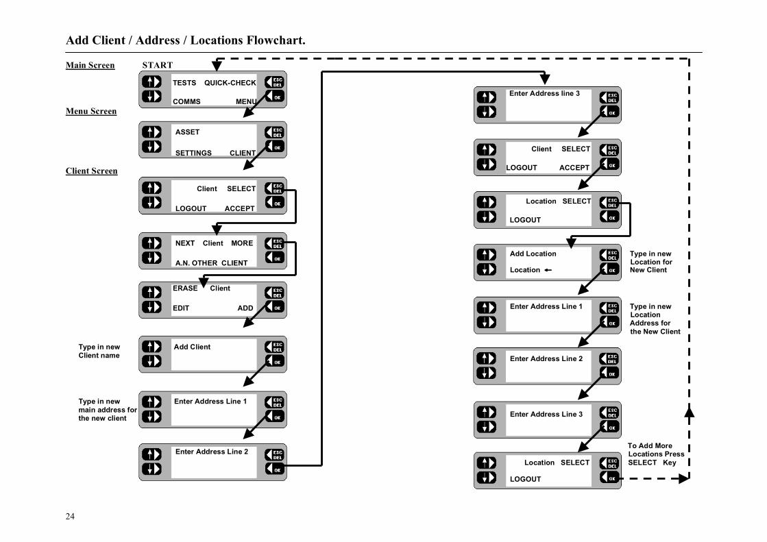
Add new Client, main Address and site Location 1. Refer to the Add Client / Address / Locations Flowchart. 2. From the Client screen, press the SELECT key. The screen
changes. 3. Press the MORE key. The screen changes. 4. Press the ADD key. The screen changes. 5. Type in the name of the new client and press the OK key. The
Address Line 1 screen is displayed. 6. Type in the first line of the Client address and press the OK key.
The Address Line 2 screen is displayed. 7. Type in the second line of the Client address and press the OK
key. The Address Line 3 screen is displayed. 8. Type in the third line of the Client address and press the OK key.
The new Client now becomes the current Client. The Client screen is displayed.
9. To accept the Client, press the ACCEPT key. The Location screen is displayed.
10. Press the SELECT key. The screen changes. 11. Add the name of the new Site Location and press the OK key.
The Address Line 1 screen is displayed. 12. Type in the first line of the Site address and press the OK key.
The Address Line 2 screen is displayed. 13. Type in the second line of the Site address and press the OK
key. The Address Line 3 screen is displayed. 14. Type in the third line of the Site address and press the OK key.
The Location screen is displayed. 15. Press the ACCEPT key The Main screen is displayed.
Add new site Location details
1. Refer to the Add Client / Address /Locations Flowchart. 2. From the Client screen press the SELECT key. The screen
changes. 3. ACCEPT the current client, or to add a location to a different
client, press the SELECT key. The screen changes. Press the NEXT key to scroll through the name list and display the required client.
4. Press the OK key. The current location is briefly displayed . The screen then changes to the Location screen .
5. Press the SELECT key. The screen changes. 6. Press the MORE key. The screen changes. 7. Press the ADD key. The screen changes. 8. Type in the name of the new site location and press the OK
key. The Address Line 1 screen is displayed. 9. Type in the details and press the OK key. The Address Line 2
screen is displayed. 10. Type in the details and press the OK key.
The Address Line 3 screen is displayed. 11. Type in the details and press the OK key. The new location
now becomes the current location. The Location screen is displayed.
12. Press the ACCEPT key. The Main screen is displayed.
Add Client / Address / Locations Flowchart.
24
Main Screen START
TESTS QUICK-CHECK
COMMS MENU
Menu Screen
ASSET
SETTINGS CLIENT Client Screen
Client SELECT
LOGOUT ACCEPT
NEXT Client MORE
A.N. OTHER CLIENT
ERASE Client
EDIT ADD
Type in new Add Client Client name
Type in new Enter Address Line 1 main address for the new client
Enter Address Line 2
Enter Address line 3
Client SELECT
LOGOUT ACCEPT
Location SELECT
LOGOUT
Add Location Type in new Location for
Location ← New Client
Enter Address Line 1 Type in new
Location Address for the New Client
Enter Address Line 2
Enter Address Line 3
To Add More Locations Press
Location SELECT SELECT Key LOGOUT

Asset Test Groups.
25
Appliances are referred to as “Assets”. For each asset a complete record is stored under the appropriate Client. Each asset record holds full details of the equipment, i.e. ID; Description; Serial number; Fuse rating; Test Group, VA Rating, Test frequency, Room, and Test results.
GROUP DETAILSe.g. DRL Drill Class 2
+ Test Setup
+ Test Limits
ASSET DETAILSDescription, Fuse Rating VA Rating,
Test requency, Last Test Date
Serial No. Group, Room
TEST RESULTSFOR
The
ASSET
ASSET
Recorde.g. DRILL
ASSET
ID
(Unique Reference)
Test Groups A Test Group is a set of pre-defined tests with associated pass / fail limits that are suitable for a specified type of asset (appliance). Up to 50 Test Groups may be configured, each of which is identified by a User designated 3-character code. Every asset record contains a Group PAT4E should use when the appliance is tested. Each Group contains the following information: - Group Code: e.g. DRL Group name: e.g. Drills Phase: Single or 3 Phase Insulation Class: Class 1 = Earthed
Class 2 = Double insulated. Reversible mains Plug: Allows repeat tests for both
orientations of reversible mains plugs. Tests to be applied: Continuity test e.g. Insulation test
Operation test etc.
When setting up a Group, any of the PAT4E tests may be specified by placing a √ next to the selected tests. For each selected test, PAT4E allows one of eight passband options to be selected. Continuity: Pass < 100mΩ, 300mΩ, 500mΩ, 750mΩ, 1.0Ω, 1.5Ω,
2.0Ω, 5.0Ω Insulation: Pass > 0.25 MΩ, 0.3 MΩ, 0.5 MΩ,1.0 MΩ, 2.0 MΩ,
7.0 MΩ, 10MΩ, 20MΩ
Operation: Pass < 50VA, 200VA, 500VA, 1000VA, 1500VA , 2000VA, 2500VA, 3000VA
Differential Earth Leakage: -
Pass < 0.25mA, 0.5mA, 0.75mA, 1.0mA, 3.5mA, 7.0mA, 10mA, and 15mA.
Substitute Discharge Earth Leakage: -
Pass < 0.25mA, 0.5mA, 0.75mA, 1.0mA, 3.5mA, 7.0mA, 10mA, and 15mA.
Absence of potential Earth Leakage: -
Pass < 0.1mA, 0.25mA, 0.5mA, 0.75mA, 1.0mA, 1.5mA, 2.0mA, and 2.5mA.
Extension lead:
Checks for correct polarity, open circuit and short circuit faults. Earth Continuity Test test: Insulation test.
Note 1: Once a Group is defined, every appliance with the same group name will have the same tests and limits applied Note 2: Groups for 3 Phase assets cannot include an Operation test.

Asset Test Groups (Continued).
26
Example:- Test Group for kettles as follows: Group Code: KET Group Description: Kettles Phase: Single Insulation Class: Class 1 RPE Continuity: Pass < 100 mΩ RISO Insulation: Pass > 2 MΩ Operation: Pass <2500 VA IPE Earth Leakage: Pass < 2 mA Mains Plug Type: Reversable Table of Test Group Combinations: -
Tests EARTH LEAKAGE METHOD
Configuration
Visual
Insulation T
est (RISO )
Run T
est
Continuity
(RPE )
Extension L
ead Polarity
Absence of
Potential (IF )
Differential
(IDIFF )
Substitute D
ischarge (IPE )
230V Appliance Class 1 ✔ ✔ ✔ ✔ ✖ ↔ ↔ ✔ 230V Appliance Class 2 ✔ ✔ ✔ ✖ ✖ ↔ ↔ ✔
230V Extension Lead Class 1 ✔ ✔ ✖ ✔ ↔ ✖ ✖ ✖ 230V Extension Lead Class 2 ✔ ✔ ✖ ✖ ↔ ✖ ✖ ✖
3 Phase Appliance Class 1 ✔ ✔ ✖ ✔ ✖ ✔ ✖ ✔ 3 Phase Appliance Class 2 ✔ ✔ ✖ ✖ ✖ ✔ ✖ ✔
✖ = Not Available. ✔ = Available. ↔ = Available with Mains lead reversal option. Note: - Only one type of Earth leakage test is permitted.

Asset Test Groups (Continued).
27
Add new Group 1. Refer to the Add Test Group Flowchart. 2. From the Menu screen, press the ASSET key. The screen
changes to the Asset, Groups, Reports screen. 3. From the Asset, Groups, Reports screen press the GROUPS
key. The screen changes. 4. Type in a 3-character code for the new group and press the OK
key. If the Group does not already exist, the option to ADD the new code is given.
Note: - If the Group code is already stored, the screen will change to offer the options to ERASE, EDIT or ADD. 5. Press the YES key. The screen changes. 6. Type in the description of the new group (10 characters max.) e.g.
Power Tools, and press the OK key. (N.B. This is the description used by AVO Form Filler T M ). The screen changes to the ‘Equipment Type selection screen.
7. The Equipment Type screen allows selection of 230Volt assets or 3 Phase Assets by using the and Keys. Complete the section using the OK key. The screen changes to the Insulation class selection screen which is initially set to Insulation Class 2.
8. Press the to change to Insulation Class 1.The screen changes to the Test selection screen.
9. Toggle the left hand keys to display optional tests for the group. To include a test for the group, insert a ✔ by pressing the OK key. Refer to Table of Test Group Combinations for available tests.
Note: - For Class 1 items, a Continuity test (RPE) can be included,
For Class 2 items a Continuity test (RPE) will not be offered. For 3 Phase options Refer to Table of Test Group Combinations.
10. When all required tests have been included, press the EXIT key.
You are now prompted with "Reversable plug?” if a reversible mains plug is in use select YES otherwise select NO.
11. For each test limit screen, toggle the left hand keys until the required setting is displayed, and press the OK key on completion of all the necessary passbands. The screen changes to the Save group to memory screen.
12. To save the new group to the memory, press the YES key. To abort the new group, press the NO key. The screen returns to the List Group screen.
Note: - If appropriate, only activate the Extension leads test with a ✔when creating a Group for Lead testing. When activated, you may also specify a polarity check, but will not be able to specify an Operation test. Edit a Group 1. Refer to the Edit/Erase Group Flowchart. 2. From the Menu screen, press the ASSET key. The screen
changes to the ‘Asset, Groups, Reports screen. 3. From the Asset, Groups, Reports screen press the GROUPS
key. The screen changes. 4. Scan in, or type in a 3-character code for the group and press the
OK key. The screen changes. 5. Press the EDIT key. The screen changes to the Group code
screen. 6. Edit the group code if necessary and press the OK key. The
screen changes to the Group name screen. 7. Edit the group name if necessary and press the OK key. The
screen changes to the Equipment Type screen. 8. Change the Equipment Type if necessary by pressing the left-
hand keys. The screen changes to the Insulation class selection screen.
9. Change the Insulation Class as necessary by pressing the left-hand keys. The screen changes to the Test selection screen.
10. Toggle the left-hand keys to select the required tests as necessary. To include a test for the group, insert a ✔by pressing the OK key. To remove a test for the group, erase the ✔ by pressing the OK key.

Asset Test Groups (Continued).
28
Note: - For Class 1 items the Earth Continuity test (RPE) can be included. If an expected Continuity test (RPE) is unavailable, it is likely that Class 2 has been inadvertently selected instead of Class 1. 11. When all required tests have been included, press the EXIT
key. Tests requiring a passband option will now be successively displayed for setting.
12. For each test limit screen, toggle the left-hand keys until the required setting is displayed. On completion, press the OK key. The screen changes to the Save group screen.
13. To save the new group to the memory, press the YES key. To abort the new group, press the NO key. The screen returns to the List Group screen.
14. Press the ESCape key to return to the Asset, Groups, Report screen.
Erase a Group A Group can be erased, provided that it does not have assets allocated to it. 1. Refer to the Edit/Erase Group Flowchart. 2. From the Menu screen, press the ASSET key. The screen
changes to the Asset, Groups, Reports screen. 3. From the Asset , Groups , Reports screen press the GROUPS
key. The screen changes. 4. Scan in, or type in a 3-character code for the group and press the
OK key. The screen changes. 5. Press the ERASE key. The screen changes. 6. Press the OK key. The selected group is erased. Note: - If the Group has assets allocated to it, it cannot be erased, and the message “The group is in use, it cannot be erased” displayed. 7. The screen returns to the Erase, Edit, Add screen.

Add Group Flowchart.
29
Menu Screen START
ASSET
SETTINGS CLIENT
ASSETS
GROUPS REPORTS
Type in a 3 Character code
LIST Group
__
Group ‘xxx’ not found
Add as a new Group ?
NO YES
Type in name ≤ 10 characters
Group name
_
Toggle Equipment Between 230 V and 3 Phase ↑ Equipment type
↓ 230 V
↑ Insulation class
↓ Class 2
Scroll UP ↑ Insulation class / DOWN To Change ↓ Class 1 CLASS
Scroll UP ↑ Tests EXIT / DOWN To
To Select all ↓ Insulation (RISO) ✔ Required Tests Selected test
= ✔
Select Required test limits for Group Scroll UP ↑ Insulation Limits / DOWN To Change ↓ > 0.5MΩ Limits
Repeat for all Tests
↑ xxxxx Limits
↓
Save group to memory
NO YES Save Group Abort
Group XXX saved

Edit / Erase Group Flowchart.
30
Menu Screen START
ASSET
SETTINGS CLIENT
ASSETS
GROUPS REPORTS
Type in a 3 Character code
LIST Group
__
Scroll UP/ ↑ Group MORE DOWN To select the ↓ TC1 required Group To ERASE Group ERASE Routine
EDIT ADD
Group code TC1_
Group name
TYP CLASS 1_
Toggle Equipment Between 230 V ↑ Equipment type and 3 Phase
↓ 230V
Scroll UP / ↑ Insulation class DOWN To Change ↓ Class 1 CLASS
Scroll UP / ↑ Tests EXIT DOWN To = ✔
To Select all ↓ Leakage (IF) ✔ Required Tests Selected test
Reversible Plug
NO YES Scroll UP/ ↑ Continuity Limits DOWN To Change ↓ < 100mΩ Limits
Repeat for all Tests
↑ xxxxx Limits
↓
Save group to memory
NO YES Save Group Abort
Group TC1 saved

Assets.
31
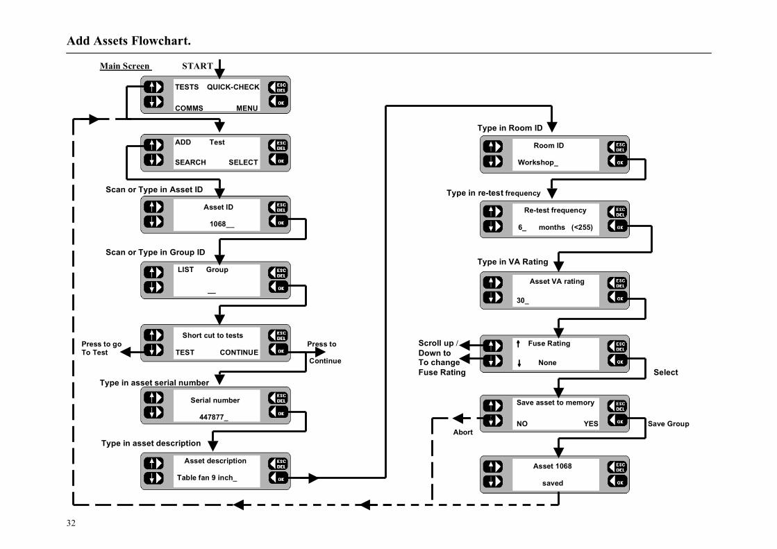
Up to 1000 assets may be stored at any one time in the PAT4E, each with their current and previous (Historic) test results. Appropriate asset details may be entered before or during testing. Once the asset record has been set and stored, it never needs to be re-entered. The next time the asset is tested, only the asset ID number needs be entered or scanned, and the PAT4E will recall the complete record with the correct Group code and all the asset details. Testing follows automatically. This approach ensures that once set up, there is no chance of the wrong tests being applied to the asset, as is possible with instruments that require a test code to be specified each time that an asset is tested. Add an Asset When entering asset details, prompts are displayed, eg, ‘Asset ID’, ‘Description’, ‘Serial no:’, ‘Fuse rating’ etc. An ‘Asset ID’ of up to 10 characters is typed in on the keyboard, or scanned in using the barcode scanner. (The PAT4E scanner will read all standard barcode formats). Other fields maybe left blank by pressing the OK key or by shortcutting to the TESTS facility. 1. Refer to the Add Asset Flowchart. 2. From the Main screen, press the TESTS key. The screen changes
to the Test screen. 3 . Press the ADD key. The screen changes. 4 . Scan in, or type in the asset ID (<10 characters) for the new asset
and press the OK key. The Group screen is displayed. 5. Scan in, or type in the Group ID (< 3 characters) and press the
OK key. The ‘Short cut to tests’ screen is displayed. 6 . Press the CONTINUE key. The screen changes to the Serial
number screen. 7. Type in the asset serial number and press the OK key. The screen
changes to the Asset description screen. 8. Scan in, or type in the asset make/model description and press the
OK key. The screen changes to the Room ID screen. The last room ID used for the selected Client is displayed.
9. Accept the displayed room ID, or type in the new room ID
name and / or number and press the OK key. The screen changes to the Re-test frequency screen.
10. Accept the default re-test frequency of 12 months, or type in the specified number of months between tests and press the OK key. The screen changes to the asset Power rating screen.
11. Type in the VA rating for the asset (often indicated as Watts) and press the OK key. The screen changes to the Fuse rating screen.
12. Toggle the left-hand keys to display the fuse rating for the asset and press the OK key (for assets without fuses, NONE may be selected). The screen changes to the Save asset screen.
13. To save the new asset to the memory, press the YES key. The option to Test asset now is given. Press the YES key to enter directly into the sequence for the selected Group.
14. To abort the new asset, press the NO key. The details are not saved and the screen returns to the Test screen.
15. Press the ESCape key to return to the Main screen. Note:-Instead of pressing the CONTINUE key (at step 6) you may
prefer to press the TEST key. This will by-pass the addition of all the remaining asset details and allows you to perform the test straight away. It is recommended that full details are entered, since these enable other features to operate such as the facility to locate an asset by Room ID.
Add Assets Flowchart.
32
Main Screen START
TESTS QUICK-CHECK
COMMS MENU
ADD Test
SEARCH SELECT
Scan or Type in Asset ID
Asset ID
1068__
Scan or Type in Group ID
LIST Group __ Short cut to tests Press to go Press to To Test TEST CONTINUE
Continue
Type in asset serial number
Serial number 447877_
Type in asset description Asset description
Table fan 9 inch_
Type in Room ID
Room ID
Workshop_
Type in re-test frequency
Re-test frequency
6_ months (<255)
Type in VA Rating
Asset VA rating
30_
Scroll up / ↑ Fuse Rating Down to To change ↓ None Fuse Rating Select
Save asset to memory
NO YES Save Group Abort
Asset 1068
saved

Assets (Continued).
33
Edit an Asset 1. Refer to the Edit or Erase an Asset Flowchart. 2. From the Menu screen, press the ASSET key. The screen
changes to the Asset, Groups, Reports screen. 3. From the Asset, Groups , Reports screen press the ASSETS
key. The screen changes. 4. Scan in, or type in the ID for the required asset and press the OK
key. The screen changes. 5. If the asset ID is recognised, the Asset screen with options to
ERASE, EDIT or ADD is displayed. Note: - If the asset ID is not recognised, the option to add as a new asset is displayed. Press the NO key to list all assets. Press the LIST key to step through the list and display the required asset, then press the MORE key. 6. Press the EDIT key. Each subsequent screen allows
amendments to be made for the selected asset. Press the OK key to sequentially step through the details.
7. To save the amended asset details to the memory, press the YES key. The screen returns to the Asset list screen. Press the ESCape key to return back to the Menu screen.
8. To abort the operation, press the NO key. The Asset screen is displayed.
Erase an Asset 1. Refer to the Edit or Erase an Asset Flowchart. 2. From the Menu screen, press the ASSET key. The screen
changes to the Asset, Groups, Reports screen. 3. From the Asset, Groups, Reports screen press the ASSETS key.
The screen changes. 4. Scan in, or type in the ID for the required asset and press the OK
key. The screen changes. 5. If the asset ID is recognised, the Asset screen with options to
ERASE, EDIT or ADD is displayed. Note: - If the asset ID is not recognised, the option to add as a new asset is displayed. Press the NO key to list all assets. Press the LIST key to step through the list and display the required asset, then press the MORE key. 6. Press the ERASE key. The screen changes. 7. Press the OK key. The selected asset is erased. The screen
returns to the Asset, Groups, Reports screen. 8. ESCape back to the Menu screen.

Edit or Erase Asset Flowchart.
34
From Menu Screen
ASSET
SETTINGS CLIENT
ASSETS
GROUPS REPORTS
LIST Asset
_
Scan or Type Asset ID
Select required Asset
NEXT Asset MORE
1068
ERASE Asset
EDIT ADD
Erase Asset
1068
Press to erase asset
Asset Erased
Asset ID
1068_
Amend if required
NEXT location ‘Anytown’ Amend if required
LIST Group
FAN_
Amend if required
Serial number
447877_
Amend if required
Asset description
Fan 9”_
Amend if required
Room ID
Workshop_
Amend if required
Re-test frequency
6_ months (<255)
Amend if required
Type in VA Rating
30_
Amend if required
↑ Fuse Rating ↓ None
Save asset to memory
NO YES
Abort Save
Asset
Asset 1068
saved

Assets (Continued).
35
Locate an Asset It may be necessary to locate and test an asset (for the current Client) for which only the Location, Test Group, or an approximate retest date is known. Search by Location 1. Refer to the Locate an Asset Flowchart. 2. From the Main screen, press the TESTS key. The Test screen is
displayed. 3. 3. From the Test screen, press the SEARCH key. The Search
Selection screen is displayed giving the option to search by DATE, LOCATION or by GROUP.
4. Press the LOCATION key. The screen changes. 5. Continue the search by selecting ROOM or LOCATION. The
screen changes. Note: - In order to search by ‘Room’, the room ID must be specified in the asset details. 6. If ROOM is selected, toggle the NEXT key to step through the
list of rooms and display the required room. Press the OK key. The screen changes.
7. If LOCATION is selected, toggle the NEXT key to step through the list of locations and display the required location. Press the OK key. The screen changes.
8. Toggle the NEXT key to step through the list of assets and display the required asset ID. Press the TEST key. The Test screen is displayed.
9. Follow the Test Asset routine. This facility is very useful if you have to test assets in a large organisation, with many different rooms. You may start in any room or location, and call up all the assets for testing before moving on to the next room or location
Search by Test Group 1. Refer to the Locate an Asset Flowchart. 2. From the Search Selection screen press the GROUP key. The
screen changes. 3. Type in the 3-character code for the Group and press the OK
key. The screen changes. Note:-If unsure of the Group code, you can use the left-hand keys to toggle the NEXT key to step through the list of Group codes. Then press the OK key. 4. Toggle the NEXT key to step through the list of assets and
display the required asset ID. 5. Press the TEST key. The Test screen is displayed. 6. Follow the Test Asset routine. Search by Test due date 1. Refer to the ‘Locate an Asset’ Flowchart. 2. From the Search screen press the DATE key. The Test due
after screen is displayed. 3. Type in the date after which the test becomes due and press the
OK key. The Test due before screen is displayed. 4. Type in the date before which the test is due and press the OK
key. The Search asset screen is displayed. 5. Toggle the NEXT key to step through the list of assets and
display the required asset ID. 6. Press the TEST key. The Test screen is displayed. 7. Follow the Test Asset routine.

Locate an Asset Flowchart.
36
Test due after
_ / /
Test due before
_ / /
Main Screen
TESTS QUICK-CHECK
COMMS MENU
ADD Test
SEARCH SELECT
DATE Search
LOCATION GROUP
Search
ROOM LOCATION
Select Required Room
NEXT Room ID Workshop NEXT Search ID:1068 TEST
Select Required Location
NEXT Location
Anytown
To Test Asset routine

Testing Assets.
37
Automated Testing PAT4E will apply each of the allocated tests for the appropriate Group, in the correct sequence. If AUTOPASS has been selected under the SETTINGS option, testing will proceed automatically with PAT4E determining the pass/fail status according to the pre selected Group limits. If MANUAL has been selected, PAT4E will pause after each test and display a Pass / Fail decision prompt. PAT4E will conduct a pre-test to confirm that electrical continuity exists within the appliance i.e. that it has been switched On, and that any fuses present are not ruptured. If the asset is very high or very low resistance, PAT4E will warn that the asset may accordingly be Open or Short Circuit. You have the option of RETRY (asset turned On?) FAIL, or IGNORE the warning. Some assets containing heating elements, filament lamps or large motors may offer very low resistance in their de-energised state, causing PAT4E to warn of a possible short circuit. In such cases, the warning can be ignored. When all required tests have been completed the results may be stored in PAT4E memory. If a printer is attached to PAT4E ’s parallel output, a simple listing of test results can be printed. If a printer is not attached or this feature has been disabled (See Settings section), PAT4E will automatically skip the printing process. Test an Asset
For an Operation test, ensure that the asset is in a safe condition to run and that no hazards are present.
1. Refer to the Test an Asset Flowchart. 2. From the Main screen, press the TESTS key. The Test screen is
displayed. 3. Press the SELECT key. The screen changes. 4. Scan in, or type in the code for the required asset and press the
OK key. The screen changes.
5. If the asset is recognised, the option to update the asset data is offered. Press the YES key to enter the ‘Edit Asset’ routine or the NO key to test the asset now.
6. Previous test results are stored, the date Last tested is displayed. Press the OK key.
Note: - If not recognised, the option to add as a new asset is displayed. Press the YES key to follow the ‘Add new asset’ routine, or press the NO key to return to the Asset ID screen. 7. If Visual inspection has been included in the Group tests, carry
out the inspection and press the PASS or FAIL key. 8. If you FAIL the asset, a list of individual visual inspection
points are progressively displayed as the respective keys are pressed. Follow the checks and press ‘YES’ for all pass conditions or ‘NO’ for any failure the failure.
Ensure that the correct leads and configurations are used for each test. Refer to diagrams located inside the lid of the PAT4E.
9. If continuing in AUTOPASS mode, the test sequence now
progresses automatically, with PAT4E deciding PASS or FAIL according to the pre-set limits for the Group. Press the OK key to step to the next test.
10. If continuing in MANUAL mode, PASS or FAIL each test result to progress to the next test in the sequence.
11. The overall Pass or Fail result is displayed. 12. If Fail is displayed, suitably label, and remove the asset from
service; investigate and rectify the fault, and re-test on completion.
Note: - A long power supply lead on an asset may cause an RPE (Protective Earth resistance) test failure, due to the high resistance of the lead. PAT4E can include lead length compensation during the test, see ‘Description of Tests’.

Test an Asset Flowchart.
38
To locate an asset routine
Asset ID not recognised
Asset 1068
not found
Add as new asset ?
NO YES
To Add an asset routine
To individual tests
Main Screen
TESTS QUICK-CHECK
COMMS MENU
ADD Test
SEARCH SELECT
Asset ID
1068_
Update asset data?
NO YES
Last tested 17/02/99 Visual inspection
FAIL PASS
Asset plugged in?
YES

Test an Asset Flowchart.
39
Type in or scan asset ID number
To edit asset routine
Test modes ‘AUTOPASS mode’ - The test sequence progresses automatically, with PAT4 E deciding ‘Pass or ‘Fail according to the pre-set limits for the ‘Group’.
‘MANUAL mode’ - Each test must be ‘Passed’ or ‘Failed’ to continue the test sequence.
Pre-testing asset
. . . . . . . .

Testing Assets (Continued).
40
Quick-Check It is often useful to perform a particular test on an asset in isolation. If for instance an asset had previously failed a particular test and had subsequently been repaired it may be useful to verify the repair before commencing with a full test sequence. Alternatively the test could be used during repair in order to highlight the area at fault. Quick-check enables the selective application of any of the tests that would normally be applied to the asset. The asset ID is entered in the normal way, recalling the asset record. The individual tests specified for the asset group will then be displayed, allowing any one to be run independently. In Quick-check mode no results are stored and the asset history in not changed. Run Quick-Check 1. Refer to the Quick-Check Flow chart adjacent. 2. From the main screen, press the Quick-Check key. The
screen changes. 3. Scan or Type in the Asset ID and press the OK key. The
Quick-Check selection screen is displayed. 4. Toggle the left-hand keys to display the required test from
the list pre-set for the group.
Ensure that the correct leads and configurations are used for each test. Refer to diagrams located inside the lid of the PAT4E. For an Operation test, ensure that the asset is in a safe condition to run and that no hazards are present.
5. Appropriate on-screen warnings are displayed for the
selected test. Comply with all instructions and press the OK key to continue.
6. Quick-Check results are displayed. Press the OK key. The option to re-test the asset is displayed.
7. Press the YES key to repeat the same test or press the NO key to return back to the Quick-Check selection screen.
8. When all Quick-Checks are completed, ESCape back to the Main screen.
9. Carry out a full test on the asset.
Main screen Start
TESTS QUICK-CHECK
COMMS MENU
Asset ID
1068_
Scroll Up / Down to select ↑ Quick Checks Required Test
↓ Insulation test RISO
Pre-testing asset
. . . . . . . .
Insulation test
Lead connected? YES
Insulation test
> 50MΩ
Insulation Res. > 50MΩ
Retest asset
NO YES

Repair Codes.
41
Form Filler T M for Windows T M has 99 built in codes which you can use when appliance testing to record repair details against tests. With your PAT4E at the end of the test, you can enter one of these codes and Form Filler T M will automatically update the repair information in the unassigned or assigned data maintenance programs. Within Form Filler T M you can modify the descriptions and add any charge for the repair. The charges will automatically be used on job costing and invoicing. A full list of repair codes currently included is shown opposite. This list may be copied and fixed inside the lid of the test instrument for easy reference if this feature is to be used. If a repair codes are not required simply press the ESCape key when the code is requested at the end of the test.
Code Description 1. Replace internal fuse. 2. Refit plug. 3. Refit socket. 4. Replace cable 5. Renew 415V 5 pin 16A 6. Renew 415V 4 pin 32A 7. Renew 415V 5 pin 32A 8. Renew IEC connector 6A 9. Renew IEC connector 10A 10. Renew IEC connector 16A 11. Replace Main Switch. 12. Replace Fuse Holder. 13. Replace Missing Screws 14. Replace Warning Labels 15. Renew 2core 1.00mm2 flex 16. Renew 2core 1.50mm2 flex 17. Renew 2core 2.50mm2 flex 18. Renew 3core 0.75mm2 flex 19. Renew 3core 1.00mm2 flex 20. Renew 3core 1.50mm2 flex 21. Renew 3core 2.50mm2 flex 22. Tighten Cord Restraints. 23. Replace Control Knobs. 24. Tighten Case fixings. 25. Replace Indicator Lamps. 26. Replace case parts

Erase Memory.
42
Scroll UP/ Down To select item to
Be erased
From time to time you may wish to permanently erase all or part of the memory on your PAT4E. Options are as follows-:
• Erase Groups • Erase Clients • Erase Locations • Erase Assets • Erase Results • Erase Setup • Erase ALL
Erase Memory 1. Refer to the Erase Memory Flowchart. 2. From the Main screen, press the MENU
key. The Menu screen is displayed. 3. From the Menu screen, press the
SETTINGS key. The Settings screen is displayed. 4. Press the MISC key. The Miscellaneous screen is displayed. 5. Press the MEMORY key. The Erase screen is displayed with
the option to select the items to be erased. 6. Toggle the left-hand keys to display the item to be erased. 7. Press the OK key. The selected items are erased. Note 1: - Once erased, the data cannot be un-erased. 8. On completion press the ESCape key to return back to the
Menu screen. Note 2: - *Erasure of Clients or Locations will include all related
assets, and is pre-empted by a check. Confirm (OK key) or cancel (ESC key) to continue.
Note 3: - *On completion of the erasure routine, PAT4E returns
to the Login screen for ‘Erase All’ and to the Client screen for ‘Erase Locations’ and ‘Erase Client’.
Note 4: - *Prior to erasing assets or results, PAT4E perform a check on the number of assets or results to be erased. Confirm OK or cancel (ESCape key)
ASSET
SETTINGS CLIENT
CLOCK
MISC USER
TEST SETUP Are you Sure?
COMPANY MEMORY NO YES
↑ Erase
↓ All Groups
↑ Erase * See Note 3
↓ All ↑ Erase
↓ Setup
↑ Erase
* See Note 4 ↓ Results
↑ Erase
* See Note 4 ↓ All Assets
↑ Erase
* See Note 2 ↓ Locations
↑ Erase * See Note 2
↓ Clients

Communications.
43
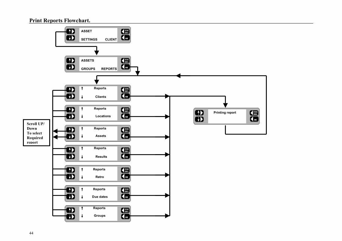
PAT4E can communicate with a printer via the parallel port or with a PC running Download Manager T M or Form Filler T M for Windows T M software via the serial port. A variety of reports are available for printing directly from the PAT4E providing the advantages of hard copy output on site. PAT4E is designed to be used in conjunction with Download Manager T M or Form Filler T M for Windows T M software which can send and receive fields within its database to form a highly integrated portable appliance testing system. PAT4E may be controlled from Download Manager T M or Form Filler T M, providing a centrally administered testing regime. In this way the manipulation of large quantities of data is handled on a PC, each PAT4E acting as a slave to receive information on Clients, Locations and assets to be tested. The data and test results can then be downloaded to the PC as convenient. Printing Reports and Test Results PAT4E enables the printing of the following range of reports: • Client List • Location List • Plain Asset List † • Assets with Current Results (Certificate of Test) • Retro report • Assets with Due dates for testing † • Groups All reports may be printed directly from the PAT4E using the parallel printer connector on the front panel. † The asset and results reports indicated list the assets and results that relate to the current Client and location. The ‘Retro’ report produces a report which is compatible with the data which may be downloaded into “Shire’s”TM ‘Safety First’, ‘Safety First+’ packages. However it must be remembered that the
output for this report selection will appear on the parallel output of the PAT4E. The above software packages can only receive data via a PC serial port. It will therefore be necessary to pass the data through a parallel to serial converter, if you wish to download from the PAT4E to any of these packages. These are readily available at low cost from many sources. Print Report 1. Refer to the Print Reports Flowchart. 2. From the Menu screen press the ASSET key. The screen
changes. 3. Press the REPORTS key. The Reports screen is displayed with
the option to select the specific report to be printed. 4. Toggle the left-hand keys to display the report to be printed. 5. Press the OK key. The selected report is printed.
6. On completion ESCape back to the Menu screen. If a printer is attached to PAT4E ’s parallel output during the testing of assets, a simple listing of test results will be printed. If a printer is not attached or this PAT4E feature has been disabled PAT4E will skip the printing process. Note:- This feature is disabled on new PAT4E ’s See Settings section),
Connect the Printer to the 25 way female ‘D’ connector using a suitable lead.
(Available as an accessory)
Print Reports Flowchart.
44
Scroll UP/ Down To select Required report
ASSET
SETTINGS CLIENT
ASSETS
GROUPS REPORTS
↑ Reports
↓ Clients
↑ Reports
Printing report ↓ Locations
↑ Reports
↓ Assets
↑ Reports
↓ Results
↑ Reports
↓ Retro
↑ Reports
↓ Due dates
↑ Reports
↓ Groups

Download / Upload Data.
45
To download and to upload data, the PAT4E needs to be connected to a PC running suitable download software. ie Download Manager T M or Form Filler T M for Windows T M. Form Filler T M for Windows T M This Windows package produces certificates for Portable Appliance Testing. The database stores a wide variety of appliance and customer information, together with a full test history. Test data may be edited, repairs added and power searches and sorts performed. Serial Lead Connections A 9 way lead is supplied with the PAT4E. The following table indicates the lead format required. Some PCs require a 25 way connector.
Personal Computer port Signal Name
PAT4E Serial Port 9 way ‘D’ 25 way ‘D’
DCD 1 7 4
RXD 2 3 2
TXD 3 2 3
DTR 4 6/8 5/6
GND 5 5 7
DSR 6 4 20
RTS 7 1 8
CTS 8 4 20
+ 5V 9 9 22 Download to a Computer 1. Connect the PAT4E to the PC, and prepare the PC software to
receive the data. 2. From the Main screen, press the COMMS key. The Comms
screen is displayed. 3. Press the SEND key. The data is downloaded. 4. On completion, ESCape back to the Main screen.
Upload from a Computer 1. Connect the PAT4E to the PC and prepare the PC software to
send the data. 2. From the Main screen, press the COMMS key. The Comms
screen is displayed. 3. Press the RECEIVE key. The Erase all current data message is
displayed, and offers the option to CONTINUE or EXIT. 4. Press the CONTINUE key. The "Are you sure" message is
displayed, and offers the option of "YES or NO"
Note: - This will erase all data. Only proceed if this data has been downloaded first, or is of no further use. The display advises that PAT4E is clearing the database, and Connecting... to the PC. 5. On completion, ESCape back to the Main screen
TESTS QUICK-CHECK
COMMS MENU
SEND Comms RECEIVE
Erase all data EXIT CONTINUE
Are you sure ?
NO YES
Clearing database
Connecting . . . .

Description of tests.
46
Note: - Refer to page 26 Table of Test Group Combinations for valid test combinations Visual Inspection List. Check the physical condition of:
Case damage; tears; cracks Mains Plug Mains Lead On/Off Switch Supply socket Environment e.g. operational hazards in the vicinity Suitability i.e. Used for correct purpose? Everything Else
Note: - If an asset fails a visual inspection, no further tests will be performed and a repair code may be entered (see ‘Repair Codes‘). Circuit Test. (Pre-Test) Prior to performing any of the main tests an initial check is performed to indicate an approximate value of appliance loop impedance. Abnormal results from this test displays a message indicating the conditions that may affect the validity of the tests to be performed, or where possible damage to the PAT4E may result. When everything is in order, no message is given. Other results obtained from this test may be: • “Appliance may be o/c” (Open circuit) - Check Asset On/Off
switch and /or fuse. • “Appliance may be s/c” (Short circuit) - Check asset before
continuing. The test is energised from a low potential / low energy a.c. supply. The open circuit voltage is typically 12 Volts (peak) with a short circuit current of 100 mA.
Insulation Test (RISO) A 500 Volt D.C. source is used to provide the Insulation test function. Class 1 appliances, are tested by applying 500V between Earth and the two-phase conductors joined together. Class 2 appliances should be tested using the IF probe as a return connection. The insulation test voltage is applied to the appliance phase conductors as for Class 1, but any current flow will return to Earth via the IF probe which should be connected to the appliance insulation or to any exposed metal parts. The insulation test has been designed to supply 500 V at 1 mA. This test is also available for three phase assets via the two front panel sockets. In this case the Red and Black leads supplied should be used to connect to the asset. Earth Continuity Test (RPE ) This test provides a measurement of protective conductor resistance and is therefore applicable to Class 1 assets only. A low current (D.C.) is passed between the Continuity terminal and the appliance test socket Earth pin. The test current is limited to 200 mA with a maximum open circuit voltage of 4 V. To use this test the RPE terminal and the black lead should be connected to the appliance exposed metalwork.. If a long appliance supply lead is used it is possible that the test may fail due to the high resistance of the lead. In this case, the COMP key on the ‘Fail or retest‘ screen can be used to include compensation for the lead length and cross sectional area. Follow the prompt to enter the lead length and press the OK key. Then use the left-hand keys to toggle and select the lead cross sectional area (and current rating) and press the OK key. PAT4E re calculates the resistance measurement and subtracts it from the original value. Only one opportunity to COMPensate the test result is offered during this sequence. This test is also available for three phase assets. In this case the Red and Black leads supplied should be used to connect to the asset using the RPE terminal and the three phase earth socket.

Description of tests.
47
Operation Test Operation tests allow the power consumed by the equipment to be checked against the manufacturers rating. The measurement is displayed in Volt Amps (VA) often specified on assets as Watts. During the Operation test the appliance is powered directly from the incoming 230 V mains supply. During the test the PAT4E also measures the mains voltage at the time of test. If this is found to vary from the nominal mains value (230 V) PAT4E will make a correction and display the consumed power as if the mains voltage had been exactly 230V. This enables a more accurate comparison with the manufacturers figure. Differential Earth Leakage Test( IDIFF). The differential earth leakage test determines whether any current is flowing to earth. Normally appliances should have no or very little earth leakage current. The PAT4E can also detect earth leakage in Class 2 (Double insulated) assets. This enables account to be taken of all leakage paths to earth rather than just that flowing in the earth wire if applicable. e.g. a Class 2 (Double insulated appliance) could exhibit earth leakage through its mountings or by operator contact. During the test the actual mains voltage is also measured at the appliance socket. In order to ensure that the equipment is safe even when the mains supply rises to its maximum permitted value (253V) the PAT4E calculates and displays the leakage current that would flow at this value. Substitute Discharge Earth Leakage Test. (IPE). This alternative Earth Leakage test is performed at 40Volts ac 50Hz. For this test the Appliance under test has its phase conductors joined together within PAT4E and a 40Volt supply is applied between both phase conductors and the Protective conductor connection of the equipment under test in the case of Class 1 equipment. In the case of
Class 2 appliances the black lead and probe is connected to the PAT4E IF terminal. This probe is applied to any conductive parts on the appliance under test. The actual voltage is measured at the appliance socket. From these readings the earth leakage current of the appliance is calculated. This calculated current is automatically scaled to the equivalent figure relevant to operation at exactly 253V. “Absence of potential” Earth Leakage Test (IF). This alternative Earth Leakage test (also known as “Touch current test”) is commonly performed on computer equipment. During this test the appliance under test is powered from its normal mains supply and the black lead and probe is connected to the PAT4E IF terminal. This probe is applied to any conductive parts on the appliance under test. This probe performs a current measurement with respect to earth. This test can also be performed on three phase appliances powered from their own supply. Fuse Test During appliance testing it is often necessary to check the integrity of a fuse. PAT4E incorporates an integral fuse tester on the front panel. To test a fuse hold the fuse to be tested onto the two pads, the PAT4E will bleep if the fuse is intact. Extension Lead Testing Most types of extension leads can be tested. Leads are tested for correct polarity (see Note1) , Insulation resistance, and Earth conductor resistance. A simple visual inspection option is also included. All leads are tested by connecting between the 230 V socket and the Lead test socket on the front panel. Where the lead to be tested is not compatible with the lead test socket a short adapter lead should be used to make the connection. See ‘Accessories’. Note 1: - Where reversible mains plugs are used the polarity check has no meaning.
On completion of the RPE test, ensure that the black lead is disconnected from the appliance under test.

Three phase Testing:- Typical configurations.
48
RPE Testing
RISO Testing
IPE Testing
Not
IF Testing
3 Phase Supply
Probe exposed metalwork

Demonstration Data.
49
To familiarise you with the features of PAT4E, sample data has been included on your instrument. In conjunction with the Quick Start Guide you will be able to become proficient with the basic features very quickly. This demonstration data can be restored to your PAT4E at any time
by powering up with the ‘R’ key depressed (see settings section). The following data has been loaded onto your instrument:
Note:- In this example, the 3 locations are on the same site, and at the same address.
Location 1: UK Site
Archcliffe Road
DOVER Kent
CT17 9EN UK
Location 2: Euro Site
Le Raincy
PARIS
FRANCE
Client 1
AVO International
Archcliffe Road
Dover UK
Location 1:
Building 1
Some Road
Some Town
Location 2:
Building 2
Some Road
Some Town
Location 3:
Building 3
Some Road
Some Town
Client 3:
Yet Another Client
Any Road
Any Town
Location 1:
Dover Site
York Street
Dover, Kent
Location 2:
Folkstone Site
Shornecliffe Road
Folkstone, Kent
Location 3:
Ashford Site
Elwick Road
Ashford, Kent
Client 2:
A. N. Other Client
Some Road
Some Town

Demonstration Data (Continued).
50
Demonstration Test Groups To enable you to get started Ten test Groups have been included to cover a variety of equipment types. They may be used, deleted or modified at any time.
Code
Usage Tests Applied Reversible Mains Lead
Pass Limits
TC1 Typical Class 1 Earthed Equipment
Visual Inspection RPE RISO Operation Test IDIFF
✔ < 0.1Ω > 2.0MΩ < 3kVA < 3.5mA
TC2 Typical Class 2 Earthed Equipment
Visual Inspection RISO Operation Test IDIFF
✔ > 7.0MΩ < 3kVA < 0.5mA
3P1 Typical Class 1 Earthed 3 Phase Equipment
Visual Inspection RPE RISO IF
✖ < 0.1Ω > 2.0MΩ < 3.5mA
3P2
Alternative Class 2 Earthed 3 Phase Equipment
Visual Inspection RISO IPE
✖ > 2.0MΩ < 3.5mA
EL1 Extension Leads 3 Wire
Visual Inspection RPE RISO Polarity
✔
< 0.1Ω > 2.0MΩ OK
EL2 Extension Leads 2 Wire
Visual Inspection RISO Polarity
✔
> 2.0MΩ OK
Code
Usage Tests Applied Reversible Mains Lead
Pass Limits
FAN
Desk Fan
Visual Inspection RISO Operation Test IDIFF
✔ > 7.0MΩ < 200VA < 0.5mA
PC Personal Computer IT Equipment
Visual Inspection RPE Operation Test IF
✔ < 0.1Ω < 200VA < 0.5mA
DRY
Hair Dryers
Visual Inspection RISO Operation Test IDIFF
✔ > 7.0MΩ < 1.5KVA < 0.5mA
KET Kettles
Visual Inspection RPE RISO Operation Test IPE
✔ < 0.1Ω >2.0MΩ < 2500VA < 3.5mA

Demonstration Data (Continued).
51
The following assets have been added for the AVO International Client at the UK Site.
Appliance ID Test Group Serial Number Description Room Re-test frequency VA Fuse F131 FAN CANA12 Canarm 3 speed Office 24 Months 60 None
F132 FAN CANA134 Canarm 3 speed Office 24 Months 60 None
T1234 TC1 None Soldering Iron Workshop 6 Months 75 None
1292-282 TC1 XER-667 Xerox Copier Sales 12 Months 900 None
T2985 PC DP-7274594 DELL Pentium Lab 1 24 Months 500 None
CFR2453 TC2 KP329 Krupps Coffee Office 12 Months 2000 None
354713 TC2 None Avery Scales Stores 12 Months 140 None
LP2345 TC2 None Desk Lamp Lab 1 12 Months 60 None
The following assets have been added for the AVO International Client at the EURO Site.
Appliance ID Test Group Serial Number Description Room Re-test frequency VA Fuse PC1 PC 1237919 DELL P560-L Support 24 Months 460 None
PC2 PC 029337 SPIRE Pentium 133 Support 24 Months 650 None
PC3 PC 13093029 DAN Pentium 200 Shop 24 Months 975 None
PC4 PC 0939287 DEL Notebook Sales 12 Months 300 None
PC5 PC 1237183 Network Server Design 24 Months 890 None
COP1 TC1 SH100-29 SHARP 2000 Shop 12 Months 800 None
KET1 KET 823-368 SWAN Slimline Old Office 12 Months 2000 None
FAN1 FAN None COOLBOY 30 Design 12 Months 75 None
FAN2 FAN None VANE 130 Design 12 Months 100 None

Demonstration Data (Continued).
52
The following assets have been added for the A. N. Other Client at the Dover Location. NB:- No other appliances exist for the other sites.
Appliance ID Test Group Serial Number Description Room Re-test frequency VA Fuse PT736 3P1 H637-27 Grinder Loan Store 3 Months None
PT874 TC1 H/23EW Flood Lights Loan Store 3 Months 1500 None
PT9805 3P2 YT/45 Power Saw Loan Store 3 Months None
PT14 TC1 FFR736 0.5” Drill Loan Store 6 Months 900 None
PT46 TC1 2763737 Sander Loan Store 6 Months 800 None
ST3880 FAN None Desk Fan Reception 12 Months 90 None
T423 TC1 None Compressor Loan Store 6 Months 2500 None
T35 TC2 None Table Light Reception 12 Months 60 None
DR36 TC2 None Table Light Reception 12 Months 60 None
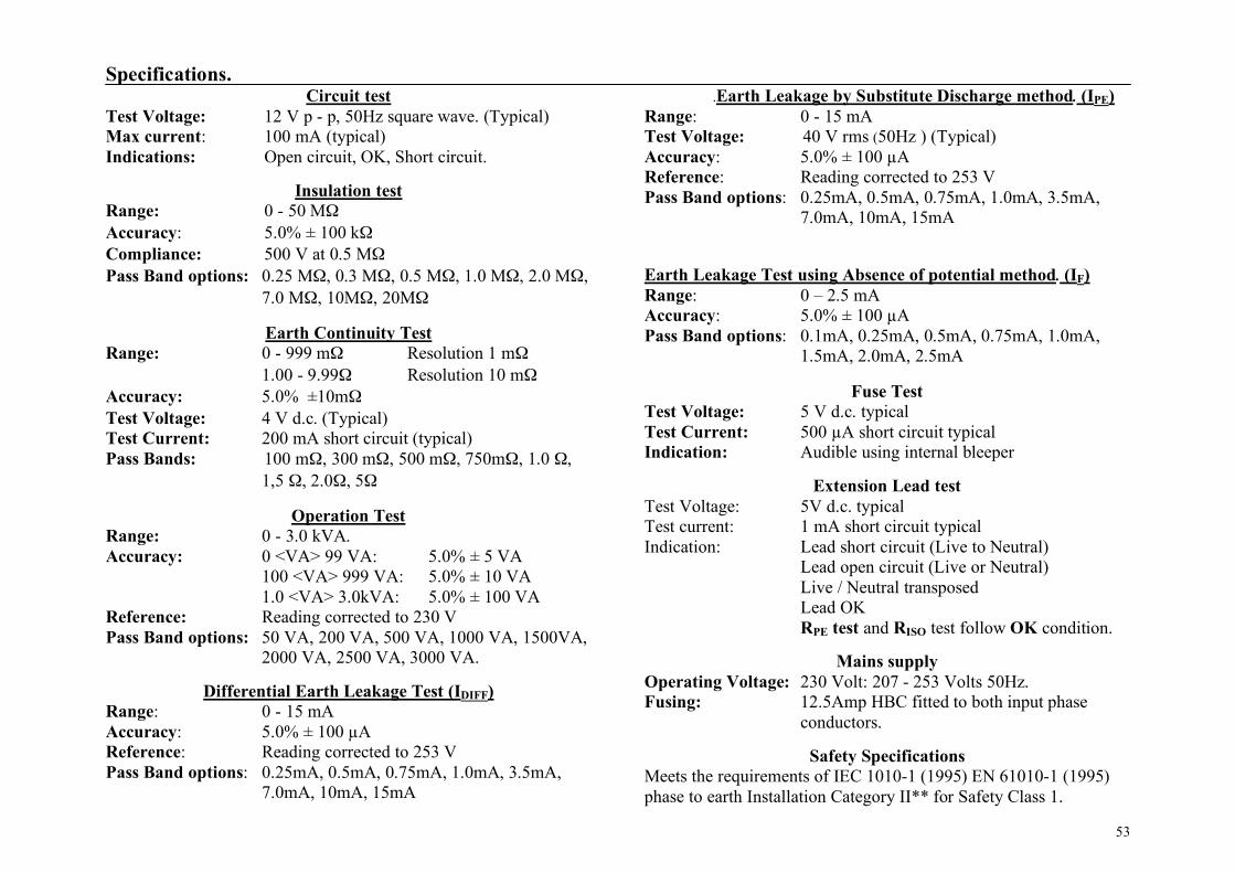
Specifications.
53
Circuit test Test Voltage: 12 V p - p, 50Hz square wave. (Typical) Max current: 100 mA (typical) Indications: Open circuit, OK, Short circuit.
Insulation test Range: 0 - 50 MΩ Accuracy: 5.0% ± 100 kΩ Compliance: 500 V at 0.5 MΩ Pass Band options: 0.25 MΩ, 0.3 MΩ, 0.5 MΩ, 1.0 MΩ, 2.0 MΩ,
7.0 MΩ, 10MΩ, 20MΩ
Earth Continuity Test Range: 0 - 999 mΩ Resolution 1 mΩ 1.00 - 9.99Ω Resolution 10 mΩ Accuracy: 5.0% ±10mΩ Test Voltage: 4 V d.c. (Typical) Test Current: 200 mA short circuit (typical) Pass Bands: 100 mΩ, 300 mΩ, 500 mΩ, 750mΩ, 1.0 Ω,
1,5 Ω, 2.0Ω, 5Ω
Operation Test Range: 0 - 3.0 kVA. Accuracy: 0 <VA> 99 VA: 5.0% ± 5 VA 100 <VA> 999 VA: 5.0% ± 10 VA 1.0 <VA> 3.0kVA: 5.0% ± 100 VA Reference: Reading corrected to 230 V Pass Band options: 50 VA, 200 VA, 500 VA, 1000 VA, 1500VA,
2000 VA, 2500 VA, 3000 VA.
Differential Earth Leakage Test (IDIFF) Range: 0 - 15 mA Accuracy: 5.0% ± 100 µA Reference: Reading corrected to 253 V Pass Band options: 0.25mA, 0.5mA, 0.75mA, 1.0mA, 3.5mA,
7.0mA, 10mA, 15mA
.Earth Leakage by Substitute Discharge method. (IPE) Range: 0 - 15 mA Test Voltage: 40 V rms (50Hz ) (Typical) Accuracy: 5.0% ± 100 µA Reference: Reading corrected to 253 V Pass Band options: 0.25mA, 0.5mA, 0.75mA, 1.0mA, 3.5mA,
7.0mA, 10mA, 15mA
Earth Leakage Test using Absence of potential method. (IF) Range: 0 – 2.5 mA Accuracy: 5.0% ± 100 µA Pass Band options: 0.1mA, 0.25mA, 0.5mA, 0.75mA, 1.0mA,
1.5mA, 2.0mA, 2.5mA
Fuse Test Test Voltage: 5 V d.c. typical Test Current: 500 µA short circuit typical Indication: Audible using internal bleeper
Extension Lead test Test Voltage: 5V d.c. typical Test current: 1 mA short circuit typical Indication: Lead short circuit (Live to Neutral) Lead open circuit (Live or Neutral) Live / Neutral transposed Lead OK RPE test and RISO test follow OK condition.
Mains supply Operating Voltage: 230 Volt: 207 - 253 Volts 50Hz. Fusing: 12.5Amp HBC fitted to both input phase
conductors.
Safety Specifications Meets the requirements of IEC 1010-1 (1995) EN 61010-1 (1995) phase to earth Installation Category II** for Safety Class 1.

Specifications (Continued).
54
EMC: Complies with Electromagnetic Compatibility Specifications (Light Industrial Category): BS/EN50081-1-1992 BS/EN50082-1-1992 Environmental Specifications Designed for indoor use or protected outdoor use. Operational Temp Range: 0° - 40° C at 90% Relative Humidity Storage Temp Range: -20° C to 60°C Temperature co-efficient: 0,2% per °C (Ref temp. 20°C) General features
Hard copy of results formatted as a pass / fail list On board real time clock module On board AVO Form Filler T M compatible asset database On board storage for 1000 test results (max) Alphanumeric key pad Auto / Manual modes Two line LCD text display
Communication Connectors 9 way male ‘D’ RS232: Interface to PC / bar code scanner 8 bits, no parity, 1 stop bit. PC: 9600 baud Scanner: 2400 baud. 25 way female ‘D’: Parallel printer for results. Cleaning Disconnect instrument from mains supply. Wipe with a clean cloth dampened with soapy water or Isopropyl Alcohol (IPA).
Mechanical Specifications. Weight: 5 kg Dimensions:
Width - 375 mm (inc handle and lid) Depth - 330 mm (inc hinges) Height - 200 mm (approx).

Accessories.
55
Included Accessories
Item Cat.No. Appliance Tester PAT4E User Guide 6172-442 Mains Lead Schuko / 16A 6121-282 Crocodile Clip (red) 6280-283 Crocodile Clip (Black) 6280-284 Test Probe (Red) 6220-529 Test Probe (Black) 6220-530 Test Lead (Red) 6220-569 Test Lead (Black) 6220-570 Test Probe Hook (Red) 6220-582 Test Probe Hook (Black) 6220-573 Serial PC Download Lead 25955-025 Download Manager Software 6111-442
Optional Accessories Item Cat.No. Bar Code Scanner 72mm 6231-623 PAT Testing Labels 6171-418 Results Printer (please refer to our Megger Applications Department for recommended alternative result printers)
6220-665
Self Adhesive Label roll for 6220-665 25995-016 Plain Paper rolls for 6220-665 10005-265 Parallel Printer Lead 25970-024 Certification software 6111-443

Repair and Warranty.
56
The instrument circuit contains static sensitive devices, and care must be taken in handling the printed circuit board. If the protection of an instrument has been impaired it should not be used, and be sent for repair by suitably trained and qualified personnel. The protection is likely to be impaired if, for example, the instrument shows visible damage, fails to perform the intended measurements, has been subjected to prolonged storage under unfavourable conditions, or has been exposed to severe transport stresses. New instruments are guaranteed for 1 Year from the Date of Purchase by the User. Note: Any unauthorised prior repair or adjustment will automatically invalidate the Warranty. Instrument Repair and Spare Parts For service requirements for MEGGER® Instruments contact:
Or an approved repair company. Approved Repair Companies A number of independent instrument repair companies have been approved for repair work on most MEGGER® instruments, using genuine MEGGER® spare parts. Consult the Appointed Distributor / Agent regarding spare parts, repair facilities and advice on the best course of action to take.
Returning an Instrument for Repair If returning an instrument to the manufacturer for repair, it should be sent freight pre-paid to the appropriate address. A copy of the Invoice and of the packing note should be sent simultaneously by airmail to expedite clearance through Customs. A repair estimate showing freight return and other charges will be submitted to the sender, if required, before work on the instrument commences.
Megger Limited Archcliffe Road Dover Kent, CT17 9EN England. Tel: +44 (0) 1304 502243 Fax: +44 (0) 1304 207342
Megger Valley Forge Corporate Center 2621 Van Buren Avenue Norristown, PA 19403 USA Tel: +1 (610) 676-8579 Fax: +1 (610) 676-8625

57
M
Megger Limited Archcliffe Road Dover Kent, CT17 9EN England Tel: +44 (0) 1304 502100 Fax: +44 (0) 1304 207342
Megger 4271 Bronze Way Dallas TX 75237-1019 U.S.A. Tel: +1 (800) 723-2861 (U.S.A. only) Tel: +1 (214) 333-3201 (International) Fax: +1 (214) 331-7399
Megger Pty Limited Unit 26 9 Hudson Avenue Castle Hill Sydney NSW 2125 Australia T +61 (0)2 9659 2005 F +61 (0)2 9659 2201 E [email protected]
Megger SARL Z.A. Du Buisson de la Couldre 23 rue Eugène Henaff 78190 TRAPPES France T +33 (0)1 30.16.08.90 F +33 (0)1 34.61.23.77 E [email protected]
This instrument is manufactured in the United Kingdom. The company reserves the right to change the specification or design without prior notice. Megger is a registered trademark. Part Number 6172- 442 V04 Printed in England 0906 www.megger.com