Passivity based control applied to power converters Marco Liserre [email protected] Passivity based...
76
Marco Liserre [email protected] Passivity based control applied to power converters Passivity based control applied to power converters Marco Liserre [email protected]
-
Upload
julian-newman -
Category
Documents
-
view
219 -
download
1
Transcript of Passivity based control applied to power converters Marco Liserre [email protected] Passivity based...
Marco Liserre [email protected]
Passivity based control applied to power converters
Passivity based control applied to power converters
Marco Liserre
Marco Liserre [email protected]
Passivity based control applied to power converters
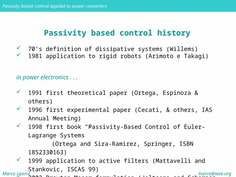
Passivity based control history
70’s definition of dissipative systems (Willems) 1981 application to rigid robots (Arimoto e Takagi)
in power electronics . . .
1991 first theoretical paper (Ortega, Espinoza & others) 1996 first experimental paper (Cecati, & others, IAS Annual
Meeting) 1998 first book “Passivity-Based Control of Euler-Lagrange
Systems” (Ortega and Sira-Ramirez, Springer, ISBN 1852330163)
1999 application to active filters (Mattavelli and Stankovic, ISCAS 99)
2002 Brayton-Moser formulation (Jeltsema and Scherpen, Am. Control Conf.)
2002 application to multilevel converters (Cecati, Dell’Aquila, Liserre, Monopoli, IECON 2002)

Marco Liserre [email protected]
Passivity based control applied to power converters
Contribution of my research group on the topic
collaborations with:
University of L’Aquila (Prof. Cecati)University of Delft (Prof. Scherpen)
main papers:
C. Cecati, A. Dell’Aquila, M. Liserre, V. G. Monopoli “A passivity-based multilevel active rectifier with adaptive compensation for traction applications” IEEE Transactions on Industry Applications, Sep./Oct. 2003, vol. 39, no. 5.
A. Dell’Aquila, M. Liserre, V. G. Monopoli, P. Rotondo “An Energy-Based Control for an n-H-Bridges Multilevel Active Rectifier” IEEE Transactions on Industrial Electronics, June 2005, vol. 52, no. 3.
Marco Liserre [email protected]
Passivity based control applied to power converters
Basic idea of the Passivity-based approach
The basic idea of the PBC is to use the energy to describe the state of the system
Since the main goal of any controller is to feed a dynamic system through a desired evolution as well as to guarantee its steady state behavior, an energy-based controller shapes the energy of the system and its variations according to the desired state trajectory
If the controller is designed aiming at obtaining the minimum energy transformation, optimum control is achieved
The PBC offers a method to design controllers that make the system Lyapunov-stable
The “energy approach” is particularly suitable when dealing with:
electromechanical systems as electrical machinesgrid connected converters (non-linear model)
Marco Liserre [email protected]
Passivity based control applied to power converters
The introduction of damping
The control objective is usually achieved through an energy reshaping process and by injecting damping to modify the dissipation structure of the system
From a circuit theoretic perspective, a PBC forces the closed-loop dynamics to behave as if there are artificial resistors — the control parameters — connected in series or in parallel to the real circuit elements
When the PBC is applied to grid connected converters, harmonic rejection is one of the main task, hence the passive damping can be substituted by a dynamic damping (i.e. virtual inductive and capacitive elements should be added)
The point of view is always the energy reshaping (i.e. the energy associated to the harmonics)
Marco Liserre [email protected]
Passivity based control applied to power converters
The Eulero-Lagrange formulation
Passivity-based control has been firstly developed on the basis of Eulero-Lagrange formulation
One of the major advantages of using the EL approach is that the physical structure (e.g., energy, dissipation, and interconnection), including the nonlinear phenomena and features, is explicitly incorporated in the model, and thus in the corresponding PBC
This in contrast to conventional techniques that are mainly based on linearized dynamics and corresponding proportional-integral–derivative (PID) or lead–lag control
Marco Liserre [email protected]
Passivity based control applied to power converters
The Passivity Based Controller design
In the context of EL-based PBC designs for power converters, two fundamental questions arise:
which variables have to be stabilized to a certain value in order to regulate the output(s) of interest toward a desired equilibrium value? In other words, are the zero-dynamics of the output(s) to be controlled stable with respect to the available control input(s), and if not, for which state variables are they stable?
where to inject the damping and how to tune the various parameters associated to the energy modification and to the damping assignment stage?
Marco Liserre [email protected]
Passivity based control applied to power converters
Dissipativity definition
dissipativity definition

Marco Liserre [email protected]
Passivity based control applied to power converters
Passivity definition

Marco Liserre [email protected]
Passivity based control applied to power converters
Definitions
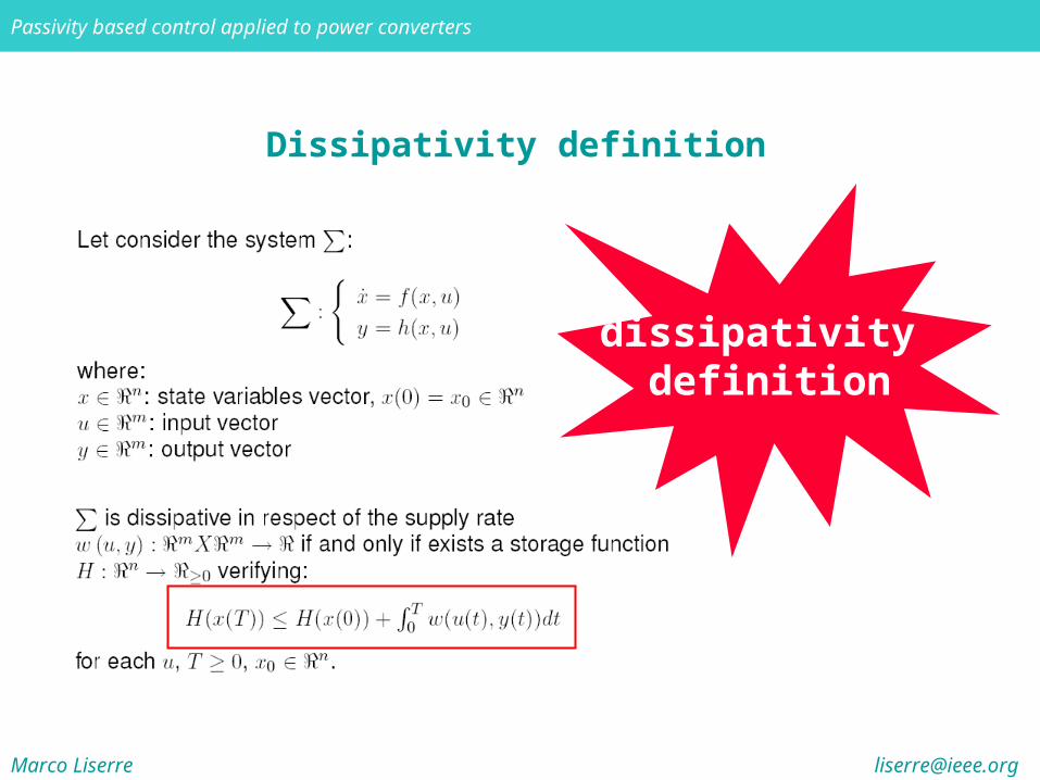
Supply Rate: speed of the energy flow from a source to the system Storage function: energy accumulated in a system Dissipative systems: systems verifying dissipation inequality:
“Along time trajectories of dissipative systems the following relationship holds:energy flow ≥ storage function”
(In other words, dissipative systems can accumulate less energy than that supplied by external sources)
The basic idea of PBC is to shape the energy of the system according to a desired state trajectory, leaving uncontrolled those parts of the system not involved in energy transformations, this result can be obtained only working on “strictly passive” systems
Marco Liserre [email protected]
Passivity based control applied to power converters
Feedback systems decomposition
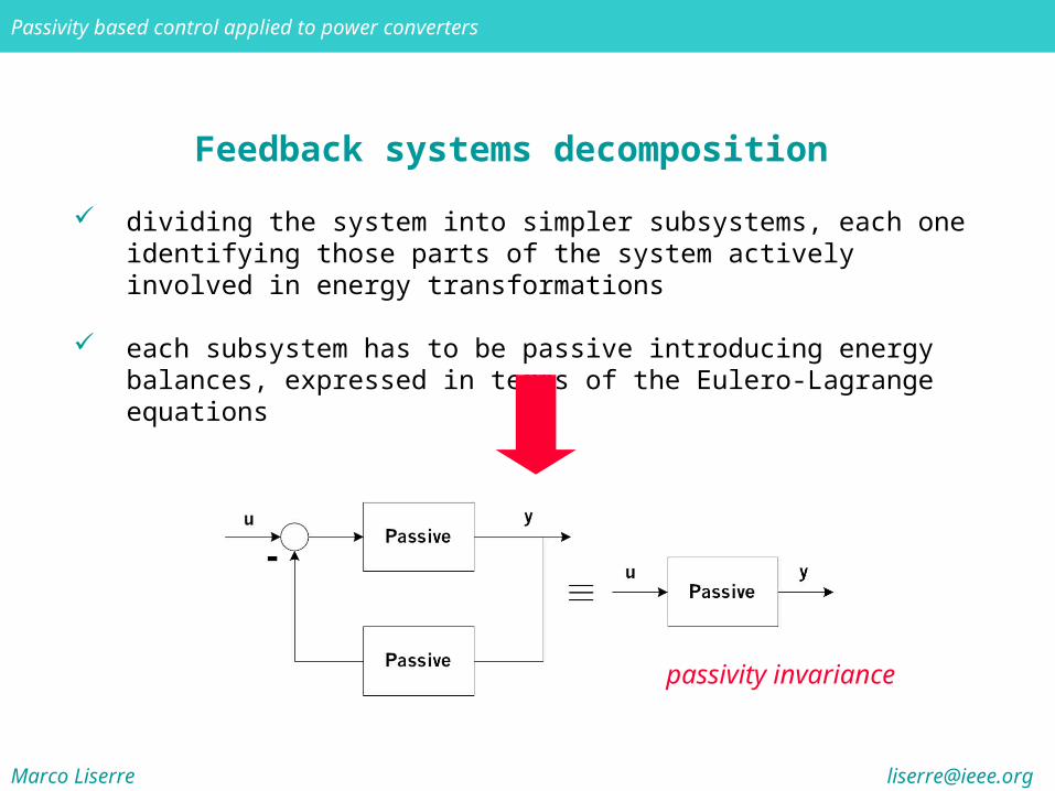
dividing the system into simpler subsystems, each one identifying those parts of the system actively involved in energy transformations
each subsystem has to be passive introducing energy balances, expressed in terms of the Eulero-Lagrange equations
passivity invariance
Marco Liserre [email protected]
Passivity based control applied to power converters
Feedback systems decomposition
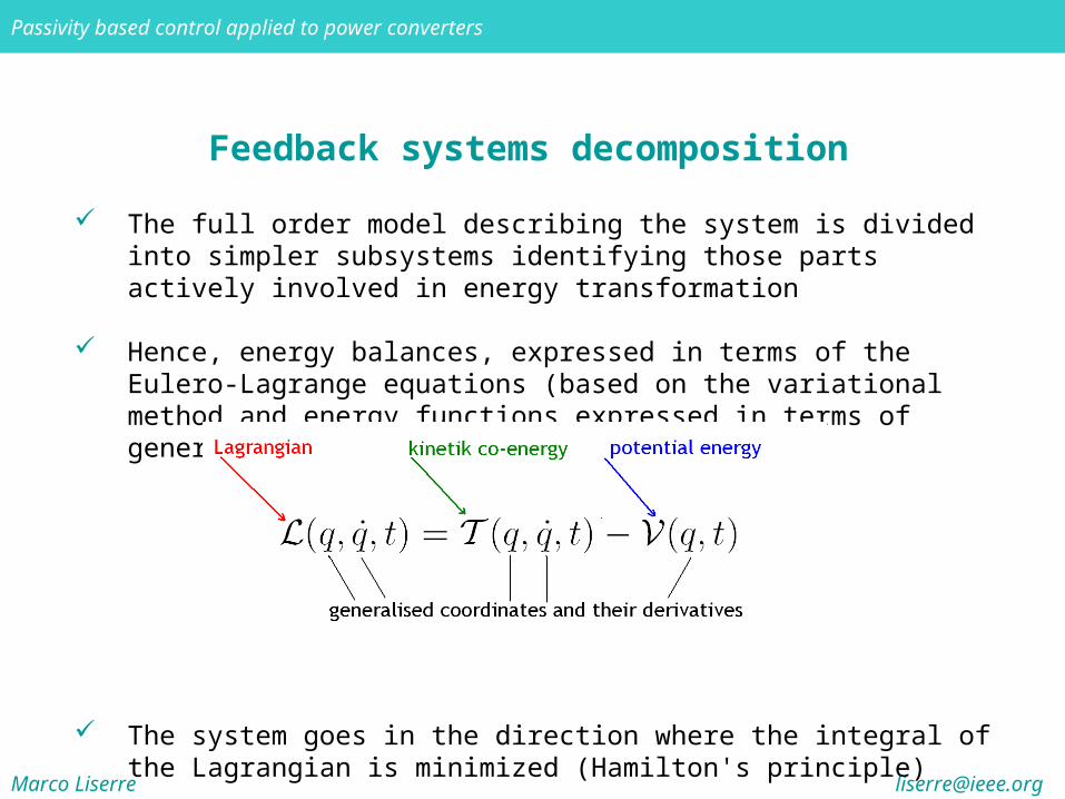
The full order model describing the system is divided into simpler subsystems identifying those parts actively involved in energy transformation
Hence, energy balances, expressed in terms of the Eulero-Lagrange equations (based on the variational method and energy functions expressed in terms of generalised coordinates), are introduced
The system goes in the direction where the integral of the Lagrangian is minimized (Hamilton's principle)
Marco Liserre [email protected]
Passivity based control applied to power converters
Feedback systems decomposition
This formulation highlights active, dissipative and workless forces i.e. the active parts of the system (those which energy can be modified by external forces), those passive (i.e. dissipating energy, e.g. thermal energy), and those parts which do not contribute in any form to control actions and can be neglected during controller design
Because of the energy approach, it is quite straightforward to obtain fast response under condition that the control "moves" the minimum amount of energy inside the system
Moreover, because global stability is ensured by passivity properties, a simple a effective controller can be designed
Marco Liserre [email protected]
Passivity based control applied to power converters
Eulero-Lagrange formulation
The eulero-lagrange formulation is particularly suited for the control of electromechanical systems as electrical motors
In fact different subsystems are related by their ability to transform energy, therefore it is a good thing to define energy functions for each one, expressed in terms of generalised coordinates qi.
In electric motor case:qm mechanical position (for mechanical subsystems)qe electric charge (for electrical subsystems)
Using variational approch we can introduce Lagrangian equations of the system and apply Hamilton's principle. This method highlights subsystems interconnections and their various energies: dissipated, stored and supplied

Marco Liserre [email protected]
Passivity based control applied to power converters
Eulero-Lagrange formulation
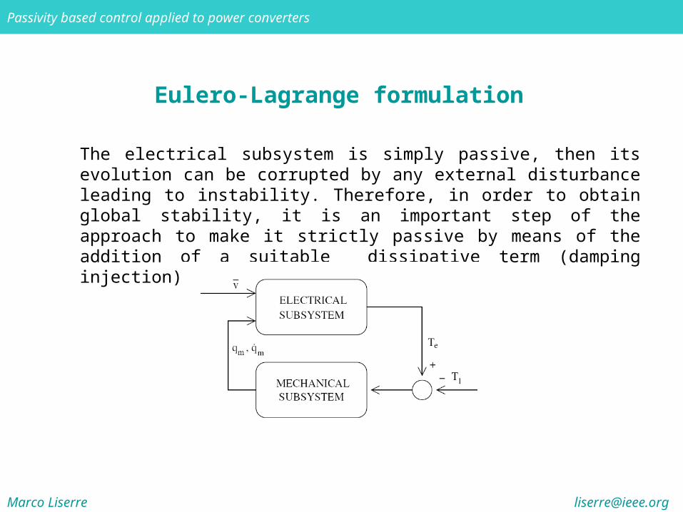
The mechanical subsystem does not take an active part in control actions, i.e. it doesn't produce energy but only transforms and dissipates the input energy, for design purposes its contribution can be considered as an external disturbance for the electrical subsystem and the controller has to compensate for this disturbance, in order to maintain electrical equation balance. In “passivity terms”, it defines a passive mapping around the electrical subsystem, it can be neglected during controller design and the attention can be focused on the electrical subsystem.
induction motor formulation
Marco Liserre [email protected]
Passivity based control applied to power converters
Eulero-Lagrange formulation
The electrical subsystem is simply passive, then its evolution can be corrupted by any external disturbance leading to instability. Therefore, in order to obtain global stability, it is an important step of the approach to make it strictly passive by means of the addition of a suitable dissipative term (damping injection)
Marco Liserre [email protected]
Passivity based control applied to power converters
Passivity-based control of the H-bridge converter
PBC has been successfully applied to d.c./d.c. converters, active rectifiers and multilevel topologies
Particularly the single-phase Voltage Source Converter (VSC) also called H-bridge or full bridge can be used as universal converter due to the possibility to perform dc/dc, dc/ac or ac/dc conversion
Moreover it can be used as basic cell of the cascade multilevel converters
In the following it will be reviewed the application of the PBC to H-bridge single phase inverters (one-stage and multilevel) using the Brayton-Moser formulation which is the most suitable for the converter control
Marco Liserre [email protected]
Passivity based control applied to power converters
Passivity-based control of the H-bridge converter
Control of one H-bridge-based active rectifierG. Escobar, D. Chevreau, R. Ortega, E. Mendes, “An adaptive passivity-based controller for a unity power factor rectifier”, IEEE Trans. on Cont. Syst. Techn., vol. 9, no. 4, July 2001, pp. 637 –644
Control of two (multilevel) H-bridge-based active rectifierC. Cecati, A. Dell'Aquila, M. Liserre and V. G. Monopoli, "A passivity-based multilevel active rectifier with adaptive compensation for traction applications", IEEE Trans. on Ind. Applicat., vol. 39, Sept./Oct. 2003 pp. 1404-1413the two dc-links are not independent !
Control of n (multilevel) H-bridge-based active rectifierA. Dell’Aquila, M. Liserre, V. G. Monopoli, P. Rotondo “An Energy-Based Control for an n-H-Bridges Multilevel Active Rectifier” IEEE Transactions on Industrial Electronics, June 2005, vol. 52, no. 3.the n dc-links are independent !
Marco Liserre [email protected]
Passivity based control applied to power converters
Brayton-Moser Equations
Brayton and Moser, introduced in 1964 a scalar function of the voltages across capacitors and the currents through inductors in order to characterize a given network
This function was called the Mixed-Potential Function P(iL, vC) and it allows to analyze the dynamics and the stability of a broad class of RLC networks
These equations can be considered an effective alternative to Euler-Lagrange formulation
This formulation has a main advantage over the counterpart in case of power converter control: it allows the controllers to be implemented using measurable quantities such as voltages and currents.

Marco Liserre [email protected]
Passivity based control applied to power converters
Topologically Complete Networks = networks which state variables form a complete set of variables
Complete Set of Variables = set of variables that can be chosen independently without violating Kirchhoff’s laws and determining either the current or voltage (or both) in every branch of the network
Additionally for Topologically Complete Networks it is possible to define two subnetworks
One subnetwork has to contain all inductors and current-controlled resistors
The other has to contain all capacitors and voltage controlled resistors
Brayton-Moser Equations
Marco Liserre [email protected]
Passivity based control applied to power converters
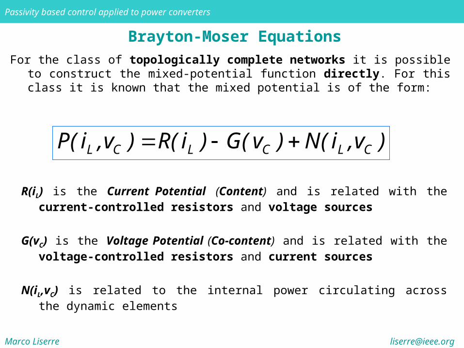
R(iL) is the Current Potential (Content) and is related with the current-controlled resistors and voltage sources
G(vC) is the Voltage Potential (Co-content) and is related with the voltage-controlled resistors and current sources
N(iL,vC) is related to the internal power circulating across the dynamic elements
Brayton-Moser Equations
For the class of topologically complete networks it is possible to construct the mixed-potential function directly. For this class it is known that the mixed potential is of the form:
L C L C L CP( i ,v ) R( i ) G( v ) N( i ,v )
Marco Liserre [email protected]
Passivity based control applied to power converters
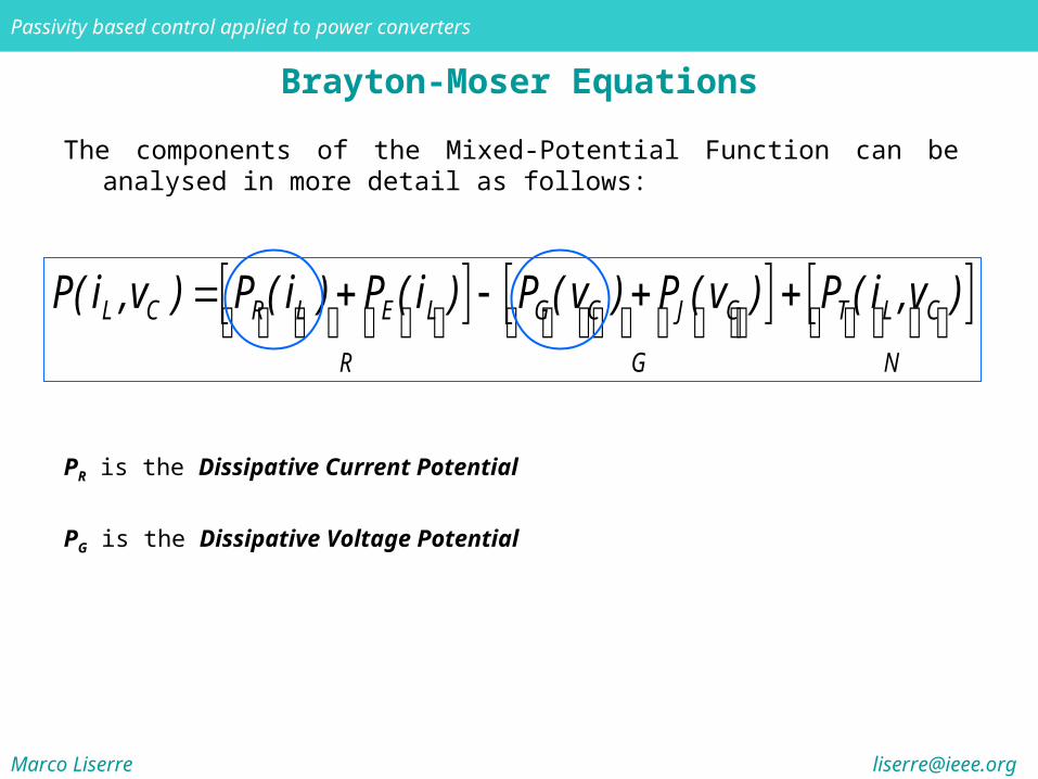
PR is the Dissipative Current Potential
PG is the Dissipative Voltage Potential
Brayton-Moser Equations
The components of the Mixed-Potential Function can be analysed in more detail as follows:
L C R L E L G C J C T L C
R G N
P( i ,v ) P ( i ) P ( i ) P ( v ) P ( v ) P ( i ,v )

Marco Liserre [email protected]
Passivity based control applied to power converters
Brayton-Moser Equations
The dissipative current and voltage potentials can be calculated as follows:
Li
R L R L L0P ( i ) v ( i' )di'
Cv
G C G C C0P ( v ) i ( v' )dv'
In case of linear resistor PR is half the dissipated power expressed in terms of inductor current, and PG is half the dissipated power expressed in terms of capacitor voltages.
PE is the total supplied power to the voltage sources E
PJ is the total supplied power to the current sources J
L C R L E L G C J C T L C
R G N
P( i ,v ) P ( i ) P ( i ) P ( v ) P ( v ) P ( i ,v )
Marco Liserre [email protected]
Passivity based control applied to power converters
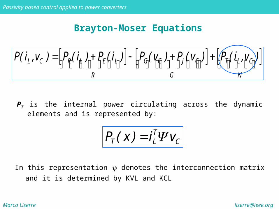
Brayton-Moser Equations
PT is the internal power circulating across the dynamic elements and is represented by:
L C R L E L G C J C T L C
R G N
P( i ,v ) P ( i ) P ( i ) P ( v ) P ( v ) P ( i ,v )
In this representation denotes the interconnection matrix and it is determined by KVL
and KCL
TT L CP ( x ) i v
Marco Liserre [email protected]
Passivity based control applied to power converters
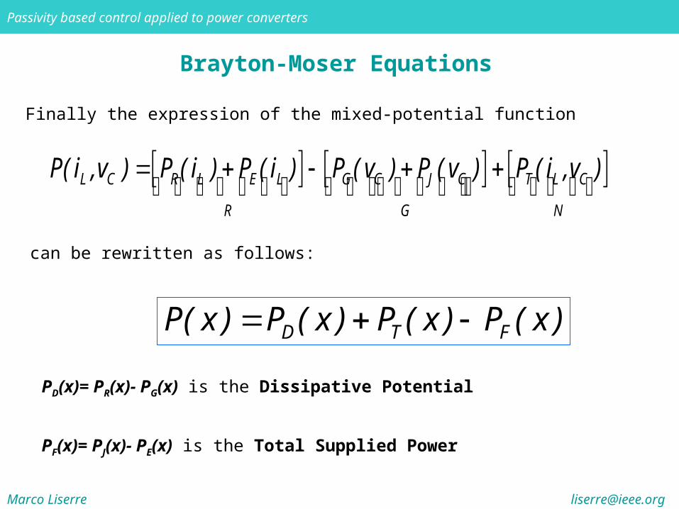
Finally the expression of the mixed-potential function
Brayton-Moser Equations
L C R L E L G C J C T L C
R G N
P( i ,v ) P ( i ) P ( i ) P ( v ) P ( v ) P ( i ,v )
can be rewritten as follows:
D T FP( x ) P ( x ) P ( x ) P ( x )
PD(x)= PR(x)- PG(x) is the Dissipative Potential
PF(x)= PJ(x)- PE(x) is the Total Supplied Power
Marco Liserre [email protected]
Passivity based control applied to power converters
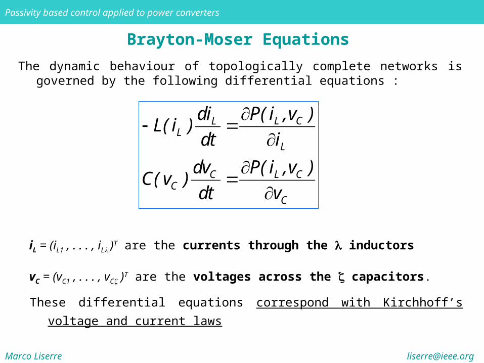
iL = (iL1 , . . . , iL )T are the currents through the inductors
vC = (vC1 , . . . , vC )T are the voltages across the capacitors.
Brayton-Moser Equations
L CLL
L
C L CC
C
P( i ,v )diL( i )
dt i
dv P( i ,v )C( v )
dt v
These differential equations correspond with Kirchhoff’s voltage and current laws
The dynamic behaviour of topologically complete networks is governed by the following differential equations :
Marco Liserre [email protected]
Passivity based control applied to power converters
Brayton-Moser Equations
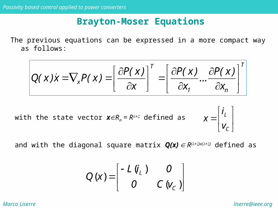
and with the diagonal square matrix Q(x) R(+)x(+) defined as
The previous equations can be expressed in a more compact way as follows:
TT
x1 n
P( x ) P( x ) P( x )Q( x )x P( x ) ...
x x x
with the state vector xRn = R+ defined as
L
C
ix
v
( )( )
( )
L
C
L i 0Q x
0 C v
Marco Liserre [email protected]
Passivity based control applied to power converters
Brayton-Moser Equations
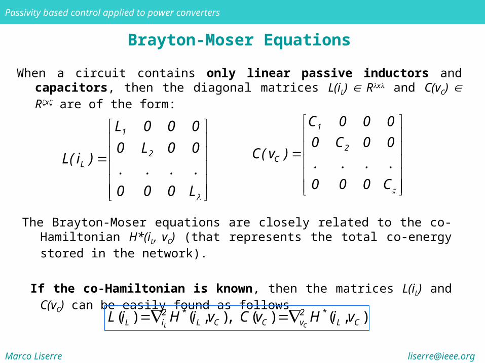
When a circuit contains only linear passive inductors and capacitors, then the diagonal matrices L(iL) Rx and C(vC) Rx are of the form:
1
2L
L 0 0 0
0 L 0 0L( i )
. . . .
0 0 0 L
1
2C
C 0 0 0
0 C 0 0C( v )
. . . .
0 0 0 C
The Brayton-Moser equations are closely related to the co-Hamiltonian H*(iL, vC) (that represents the total co-energy stored in the network).
If the co-Hamiltonian is known, then the matrices L(iL) and C(vC) can be easily found as follows
* *( ) ( , ), ( ) ( , ) L C
2 2L i L C C v L CL i H i v C v H i v
Marco Liserre [email protected]
Passivity based control applied to power converters
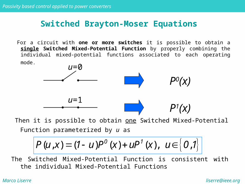
Switched Brayton-Moser Equations
For a circuit with one or more switches it is possible to obtain a single Switched Mixed-Potential Function by properly combining the individual mixed-potential
functions associated to each operating mode. u=0
P0(x)
u=1P1(x)
Then it is possible to obtain one Switched Mixed-Potential Function parameterized by
u as
( , ) ( ) ( ) ( ), , 0 1P u x 1 u P x uP x u 0 1The Switched Mixed-Potential Function is consistent with the individual Mixed-
Potential Functions

Marco Liserre [email protected]
Passivity based control applied to power converters
Switched Brayton-Moser Equations
It is worth to notice that the only difference between each individual Mixed-Potential
Function and the Switched Mixed-Potential Function will be in the term
and in particular in the interconnection matrix which becomes a function of u, (u)
TT L CP ( x ) i v

Marco Liserre [email protected]
Passivity based control applied to power converters
Average State Model
When the switching frequency is sufficiently high, it is possible to prove that the average state model of a circuit with a single switch can be derived from the discrete model by only replacing the discrete variable u{0,1} with the continuously varying duty-cycle variable μ[0,1] . Additionally, to show that the model is a state average model, the state vector x is replaced by the state average vector z
Discrete
Model
Average
State
Model
uμ
xz

Marco Liserre [email protected]
Passivity based control applied to power converters
Average State Model
The former result can be extended to circuits with multiple switches. In this case the matrix (u) assumes as many configurations as the possible combinations of the status of the switches are (e. g. for an H-bridge converter is a mono-dimensional matrix and may assume three distinct values {-1,0,1})
Discrete
Model
Average
State
Model
uiμi
xizi
Marco Liserre [email protected]
Passivity based control applied to power converters
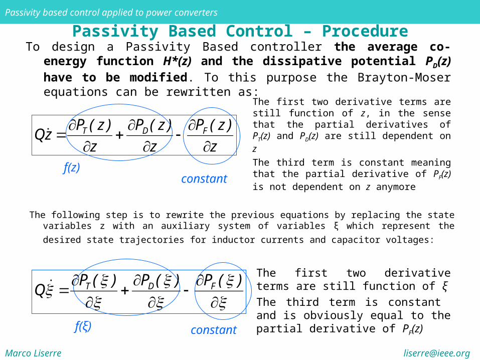
Passivity Based Control – ProcedureTo design a Passivity Based controller the average co-energy function H*(z) and the
dissipative potential PD(z) have to be modified. To this purpose the Brayton-Moser equations can be rewritten as:
The first two derivative terms are still function of z, in the sense that the partial derivatives of PT(z) and PD(z) are still dependent on z
The third term is constant meaning that the partial derivative of PF(z) is not dependent on z anymore
T D FP ( z ) P ( z ) P ( z )
Qzz z z
f(z)constant
The following step is to rewrite the previous equations by replacing the state variables z with an auxiliary system of variables ξ which represent the desired state trajectories for
inductor currents and capacitor voltages:
f(ξ) constant
T D FP ( ) P ( ) P ( )
QThe first two derivative terms are still function of ξ
The third term is constant and is obviously equal to the partial derivative of PF(z)
Marco Liserre [email protected]
Passivity based control applied to power converters
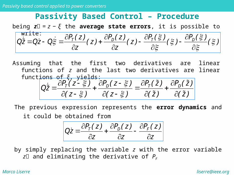
Passivity Based Control – Procedurebeing z = z − ξ the average state errors, it is possible to write:
Assuming that the first two derivatives are linear functions of z and the last two derivatives are linear functions of ξ, yields:
T D T DP ( z ) P ( z ) P ( ) P ( )
Qz Qz Q ( z ) ( z ) ( ) ( )z z
T D T DP ( z ) P ( z ) P ( z ) P ( z )
Qz( z ) ( z ) ( z ) ( z )
The previous expression represents the error dynamics and it could be obtained from
T D FP ( z ) P ( z ) P ( z )
Qzz z z
by simply replacing the variable z with the error variable z and eliminating the derivative of PF
Marco Liserre [email protected]
Passivity based control applied to power converters
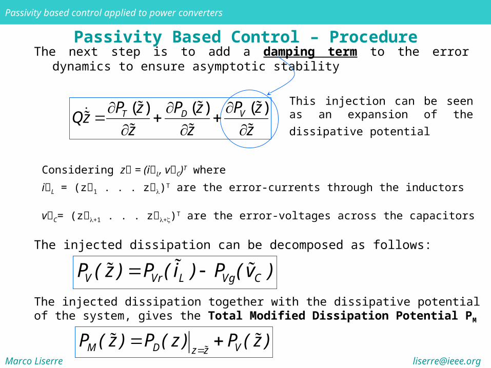
Passivity Based Control – ProcedureThe next step is to add a damping term to the error dynamics to ensure asymptotic
stability
This injection can be seen as an
expansion of the dissipative potential ( )( ) ( )
VT D P zP z P zQz
z z z
Considering z = (iL, vC)T where
iL = (z1 . . . z)T are the error-currents through the inductors
vC= (z+1 . . . z+)T are the error-voltages across the capacitors The injected dissipation can be decomposed as follows:
V Vr L Vg CP ( z ) P ( i ) P ( v )
The injected dissipation together with the dissipative potential of the system, gives the Total Modified Dissipation Potential PM
M D Vz z
P ( z ) P ( z ) P ( z )
Marco Liserre [email protected]
Passivity based control applied to power converters
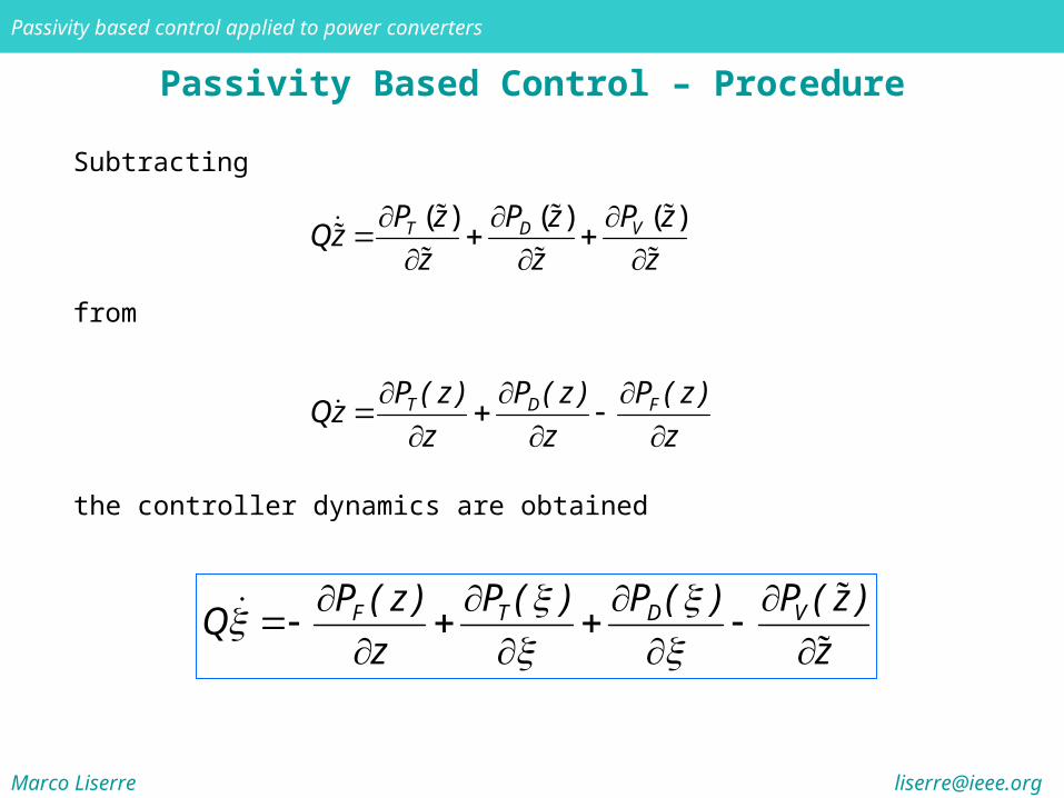
Passivity Based Control – Procedure
the controller dynamics are obtained
VF T D P ( z )P ( z ) P ( ) P ( )
Qz z
Subtracting
( )( ) ( )
VT D P zP z P z
Qzz z z
from
T D FP ( z ) P ( z ) P ( z )
Qzz z z
Marco Liserre [email protected]
Passivity based control applied to power converters
Passivity Based Control – Procedure
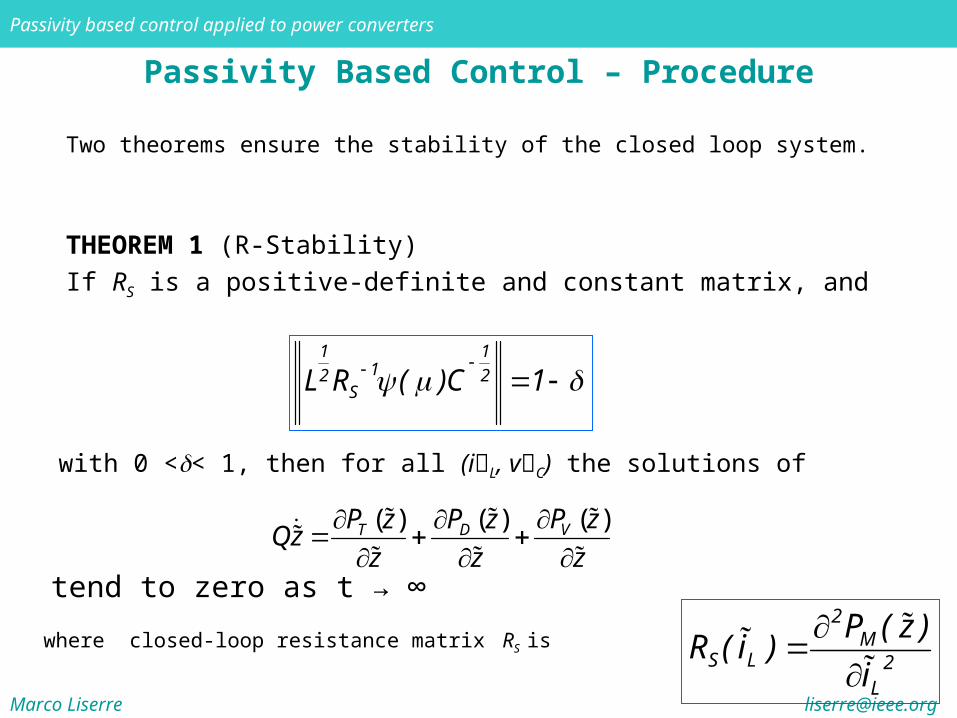
THEOREM 1 (R-Stability)
If RS is a positive-definite and constant matrix, and
Two theorems ensure the stability of the closed loop system.
1 112 2
SL R ( )C 1
with 0 << 1, then for all (iL, vC) the solutions of
tend to zero as t → ∞
( )( ) ( )
VT D P zP z P z
Qzz z z
where closed-loop resistance matrix RS is
2M
S L 2L
P ( z )R ( i )
i
Marco Liserre [email protected]
Passivity based control applied to power converters
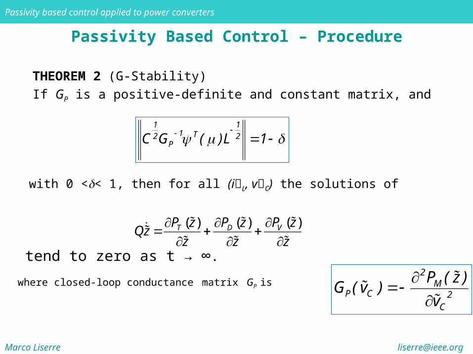
Passivity Based Control – Procedure
THEOREM 2 (G-Stability)
If GP is a positive-definite and constant matrix, and
with 0 << 1, then for all (iL, vC) the solutions of
tend to zero as t → ∞.
( )( ) ( )
VT D P zP z P z
Qzz z z
1 11 T2 2
PC G ( )L 1
where closed-loop conductance matrix GP is
2M
P C 2C
P ( z )G ( v )
v
Marco Liserre [email protected]
Passivity based control applied to power converters
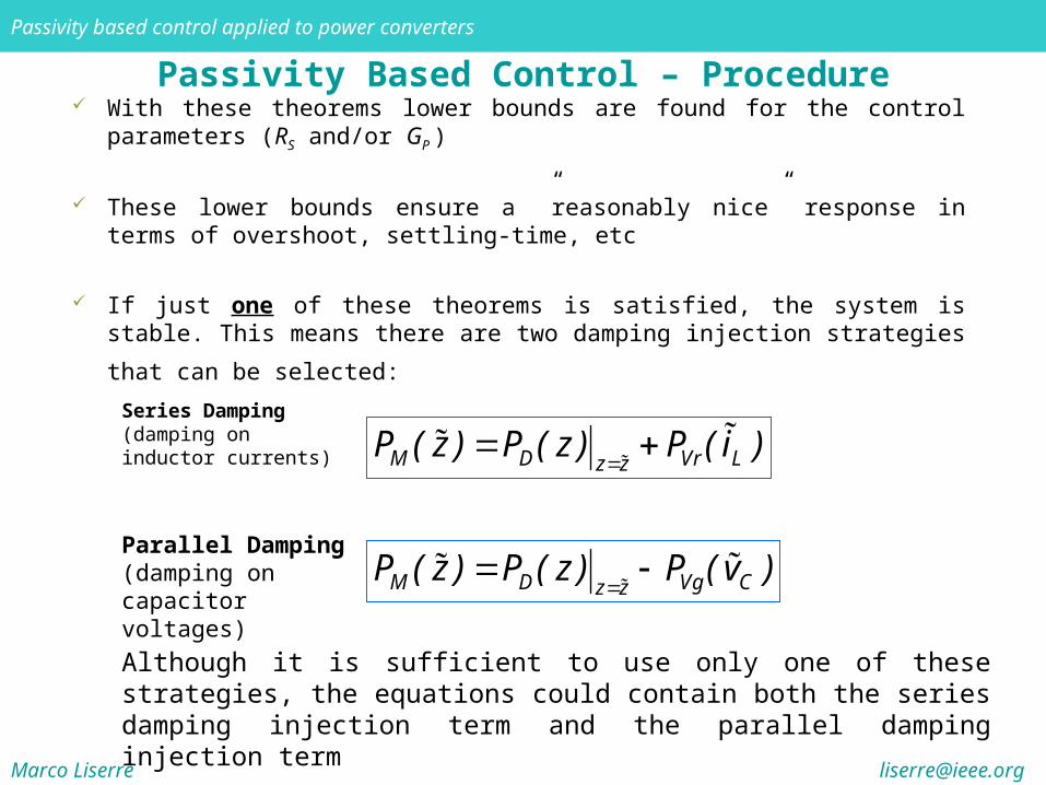
Passivity Based Control – Procedure With these theorems lower bounds are found for the control parameters (RS
and/or GP )
These lower bounds ensure a ”reasonably nice” response in terms of overshoot, settling-time, etc
If just one of these theorems is satisfied, the system is stable. This means there
are two damping injection strategies that can be selected:
Although it is sufficient to use only one of these strategies, the equations could contain both the series damping injection term and the parallel damping injection term
Series Damping (damping on inductor currents)
M D Vr Lz z
P ( z ) P ( z ) P ( i )
Parallel Damping (damping on capacitor voltages)
M D Vg Cz z
P ( z ) P ( z ) P ( v )
Marco Liserre [email protected]
Passivity based control applied to power converters
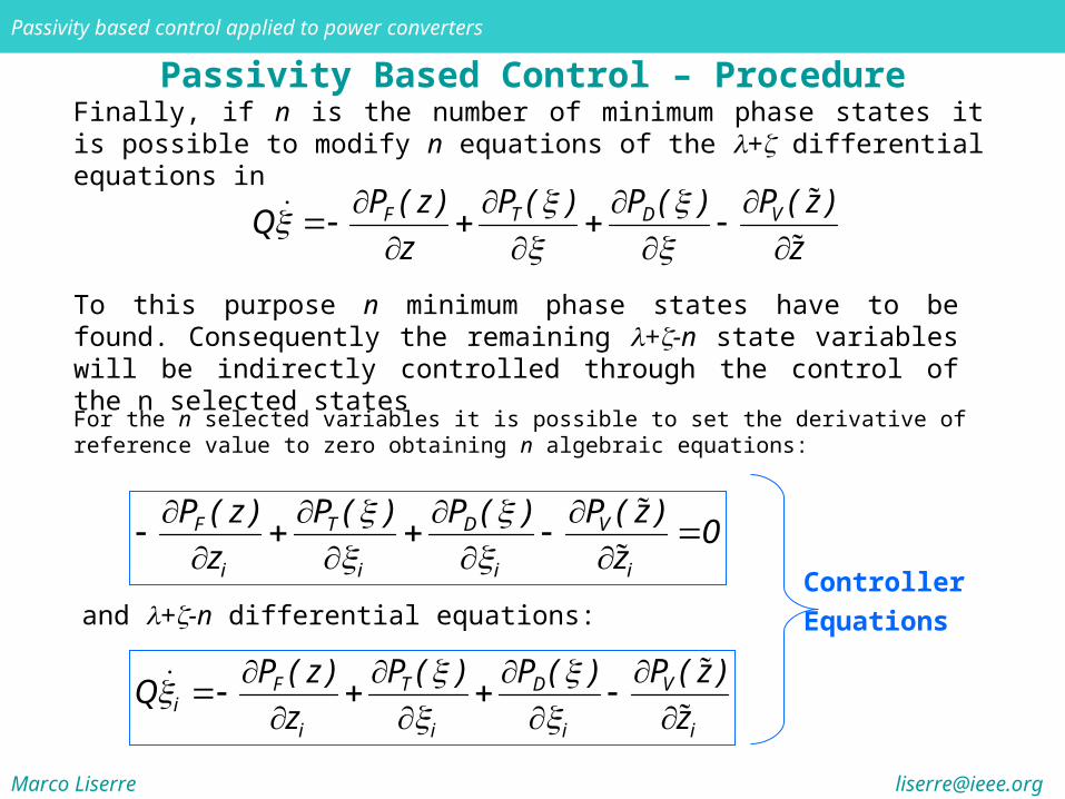
Passivity Based Control – ProcedureFinally, if n is the number of minimum phase states it is possible to modify n equations of the + differential equations in
To this purpose n minimum phase states have to be found. Consequently the remaining +-n state variables will be indirectly controlled through the control of the n selected states
VF T D P ( z )P ( z ) P ( ) P ( )
Qz z
For the n selected variables it is possible to set the derivative of reference value to zero obtaining n algebraic equations:
and +-n differential equations:
VF T D
i i i i
P ( z )P ( z ) P ( ) P ( )0
z z
VF T D
ii i i i
P ( z )P ( z ) P ( ) P ( )Q
z z
Controller
Equations
Marco Liserre [email protected]
Passivity based control applied to power converters
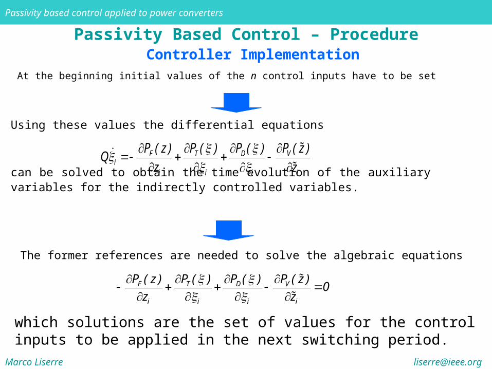
Passivity Based Control – Procedure
At the beginning initial values of the n control inputs have to be set
Controller Implementation
Using these values the differential equations
can be solved to obtain the time evolution of the auxiliary variables for the indirectly controlled variables.
VF T D
ii i i i
P ( z )P ( z ) P ( ) P ( )Q
z z
The former references are needed to solve the algebraic equations
VF T D
i i i i
P ( z )P ( z ) P ( ) P ( )0
z z
which solutions are the set of values for the control inputs to be applied in the next switching period.
Marco Liserre [email protected]
Passivity based control applied to power converters
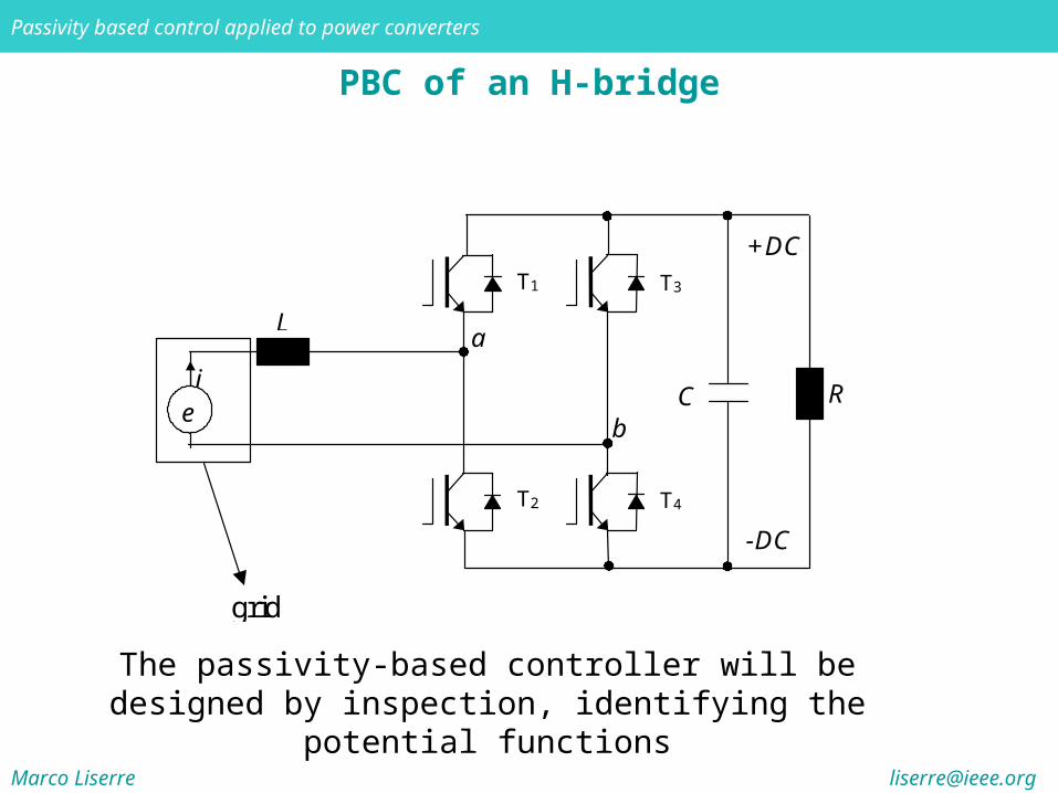
PBC of an H-bridge
a
C Ri
e
L
b
+DC
-DC
grid
T1
T2
T3
T4
The passivity-based controller will be designed by inspection, identifying the potential functions
Marco Liserre [email protected]
Passivity based control applied to power converters
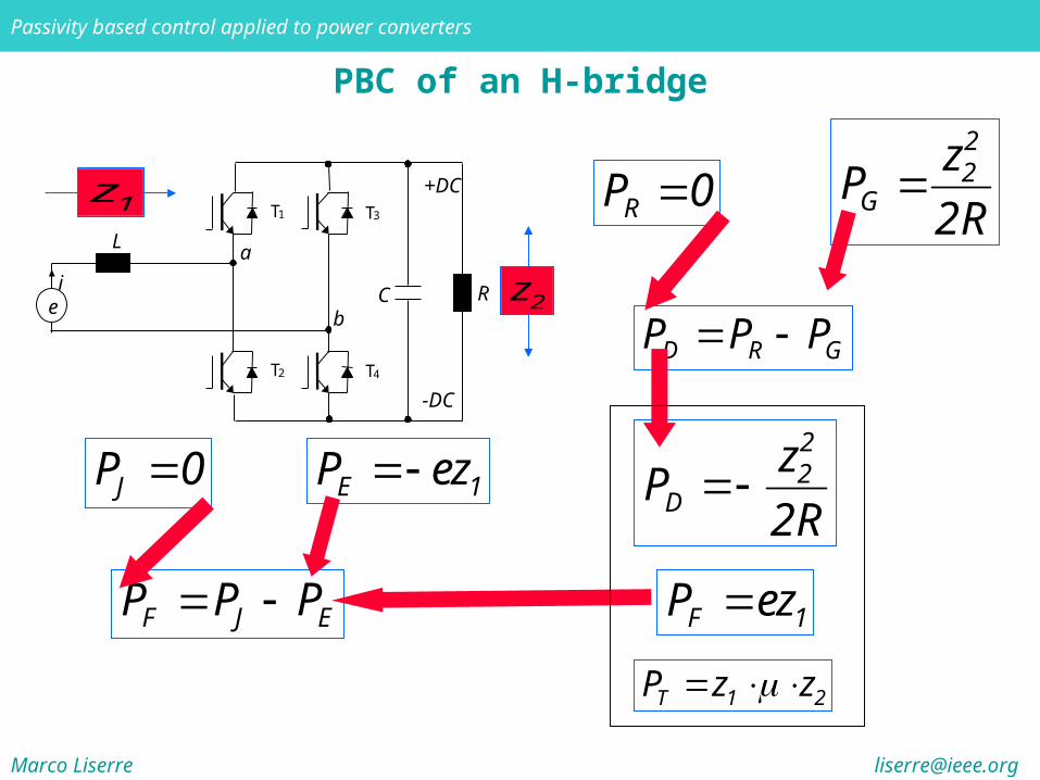
PBC of an H-bridge
D R GP P P
a
C Rie
L
b
+DC
-DC
T1
T2
T3
T4
RP 022
G
zP
2R
22
D
zP
2R
1z
2z
F J EP P P
JP 0 E 1P ez
F 1P ez
T 1 2P z z
Marco Liserre [email protected]
Passivity based control applied to power converters
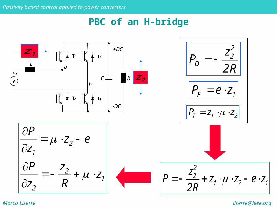
PBC of an H-bridge
a
C Rie
L
b
+DC
-DC
T1
T2
T3
T4
1z
2z
22
D
zP
2R
F 1P e z
T 1 2P z z
22
1 2 1
zP z z e z
2R
21
21
2
Pz e
z
P zz
z R
Marco Liserre [email protected]
Passivity based control applied to power converters
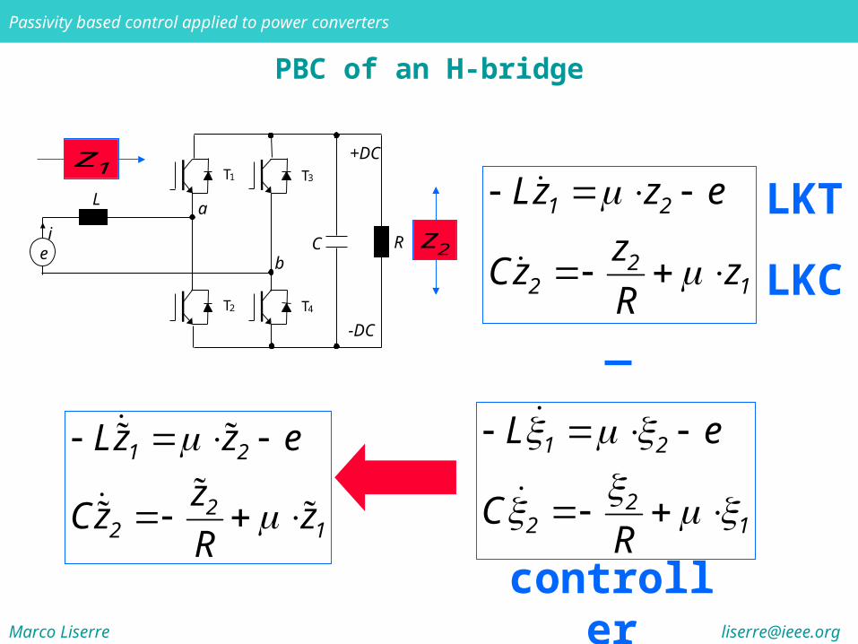
PBC of an H-bridge
a
C Rie
L
b
+DC
-DC
T1
T2
T3
T4
1z
2z1 2
22 1
Lz z e
zCz z
R
LKT
LKC
1 2
22 1
L e
CR
controller
1 2
22 1
Lz z e
zCz z
R
Marco Liserre [email protected]
Passivity based control applied to power converters
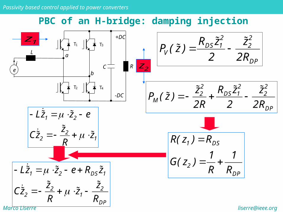
PBC of an H-bridge: damping injection
a
C Rie
L
b
+DC
-DC
T1
T2
T3
T4
1z
2z
2 2DS 1 2
VDP
R z zP ( z )
2 2R
22 2DS 12 2
MDP
R zz zP ( z )
2R 2 2R
1 DS
2DP
R( z ) R
1 1G( z )
R R
1 2
22 1
Lz z e
zCz z
R
1 2 DS 1
2 22 1
DP
Lz z e R z
z zCz z
R R
Marco Liserre [email protected]
Passivity based control applied to power converters
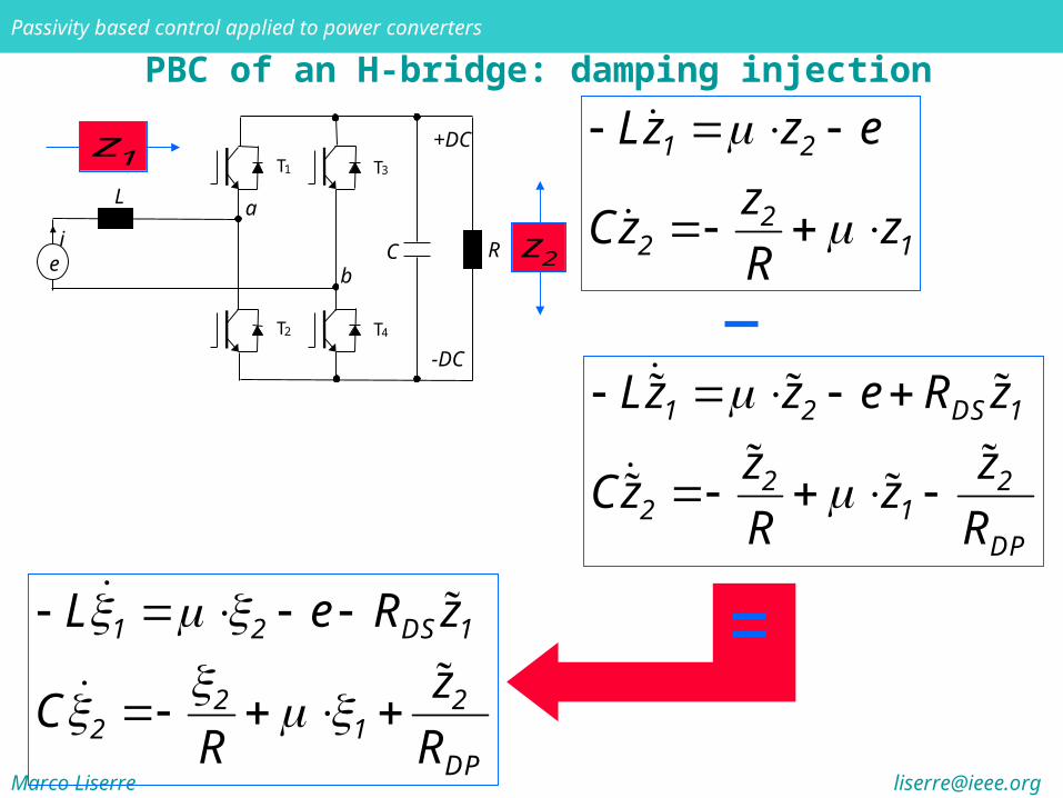
PBC of an H-bridge: damping injection
a
C Rie
L
b
+DC
-DC
T1
T2
T3
T4
1z
2z
1 2 DS 1
2 22 1
DP
Lz z e R z
z zCz z
R R
1 2
22 1
Lz z e
zCz z
R
1 2 DS 1
2 22 1
DP
L e R z
zC
R R

Marco Liserre [email protected]
Passivity based control applied to power converters
PBC of an H-bridge: control variables
a
C Rie
L
b
+DC
-DC
T1
T2
T3
T4
1z
2z
1 2 DS 1
2 22 1
DP
L e R z
zC
R R
which variables have to be stabilized to a certain value in order to regulate the output(s) of interest toward a desired equilibrium value?
in other words, are the zero-dynamics of the output(s) to be controlled stable with respect to the available control input(s), and if not, for which state variables are they stable?
Marco Liserre [email protected]
Passivity based control applied to power converters
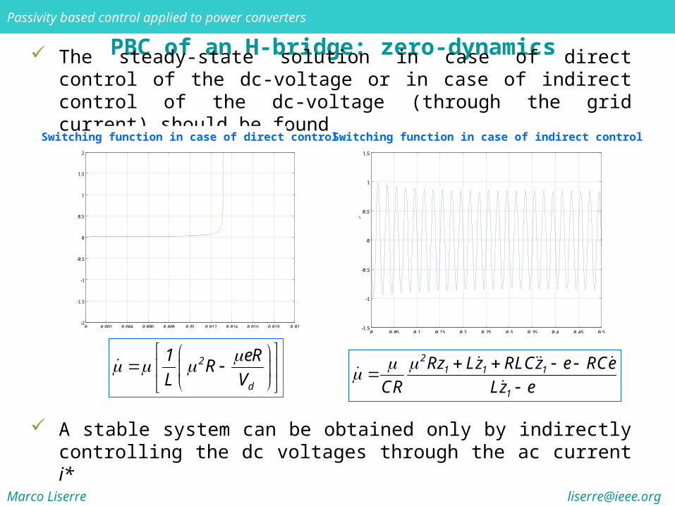
PBC of an H-bridge: zero-dynamics The steady-state solution in case of direct control of the dc-voltage or in
case of indirect control of the dc-voltage (through the grid current) should be found
Switching function in case of direct control
0 0.002 0.004 0.006 0.008 0.01 0.012 0.014 0.016 0.018 0.02-2
-1.5
-1
-0.5
0
0.5
1
1.5
2
Funz
ione
di s
witc
hing
s
Tempo [s] 0 0.05 0.1 0.15 0.2 0.25 0.3 0.35 0.4 0.45 0.5-1.5
-1
-0.5
0
0.5
1
1.5
Fu
nzi
on
e d
i sw
itch
ing
s
Tempo [s]
Switching function in case of indirect control
21 1 1
1
Rz Lz RLCz e RCe
CR Lz e
2
d
1 eRR
L V
A stable system can be obtained only by indirectly controlling the dc voltages through the ac current i*

Marco Liserre [email protected]
Passivity based control applied to power converters
as i i*, vc ξ2 Vd
PBC of an H-bridge
reference voltage Vd
and load conductance θ
power balancereference current i*
internally generated ξ2
ODEswitching function µ
algebraic
A stable system can be obtained only by indirectly controlling the dc voltages through the ac current i*
This means that
E
VI d
d
22
and *di I sin t
1
1
*2 DS 1
*2 2 DP 2
Lz e R z
C z G z
load conductancedc voltage reference
grid voltage amplitudecontroller
R
1
From the power balance it results that
Marco Liserre [email protected]
Passivity based control applied to power converters
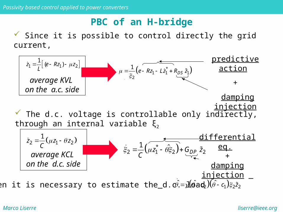
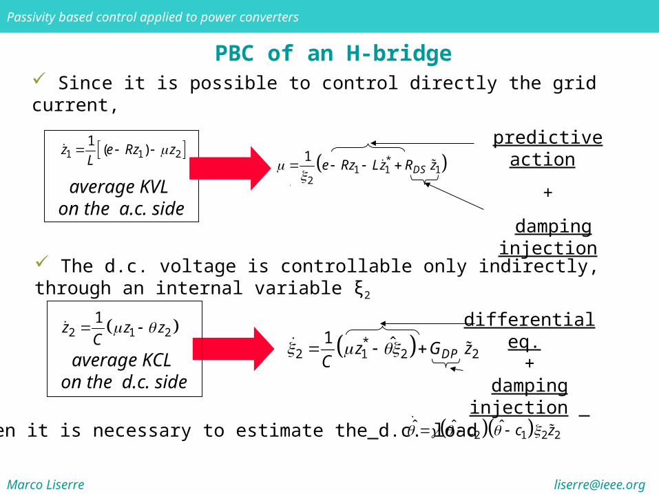
PBC of an H-bridge Since it is possible to control directly the grid current,
The d.c. voltage is controllable only indirectly, through an internal variable ξ2
1 1 21
( )z e Rz zL
average KVL on the a.c. side
*1 1 1
2
1DSe Rz Lz R z
predictive action
+
damping injection
average KCL on the d.c. side
differential eq. +
damping injection
Then it is necessary to estimate the d.c. load
2 1 21 z z zC *
2 1 2 21 ˆ
DPz G zC
2 1 2 2ˆ ˆ ˆ c c z
Marco Liserre [email protected]
Passivity based control applied to power converters
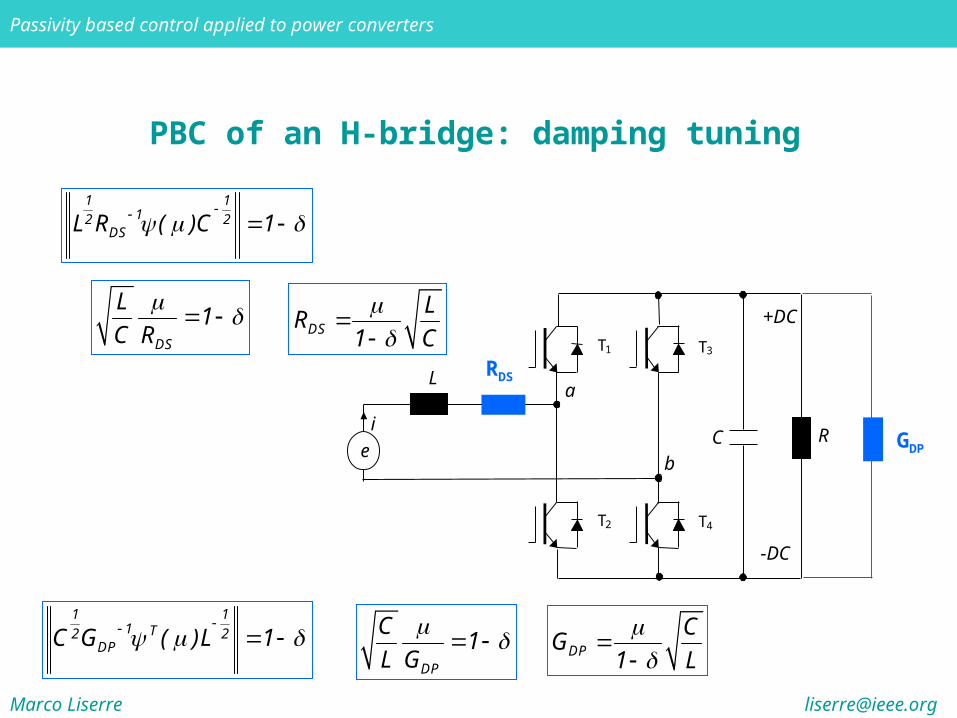
PBC of an H-bridge: damping tuning
1 112 2
DSL R ( )C 1
1 11 T2 2
DPC G ( )L 1
DS
L1
C R
DP
C1
L G
a
C Ri
e
L
b
+DC
-DC
T1
T2
T3
T4
DS
LR
1 C
DP
CG
1 L
RDS
GDP
Marco Liserre [email protected]
Passivity based control applied to power converters
Passivity Control of the Multilevel Converter
The use of the passivity-based control (PBC) properly fits stability problems related to this type of converter
Two approaches for the PBC design have been considered
the first is developed considering the overall multilevel converter
the second is developed by splitting the system into n subsystems and controlling them independently
As regards the second, the partition of the multilevel converter is done on the basis of energy considerations
The main advantage of the second approach is the separate control of the different DC-links and a flexible loading capability
Marco Liserre [email protected]
Passivity based control applied to power converters
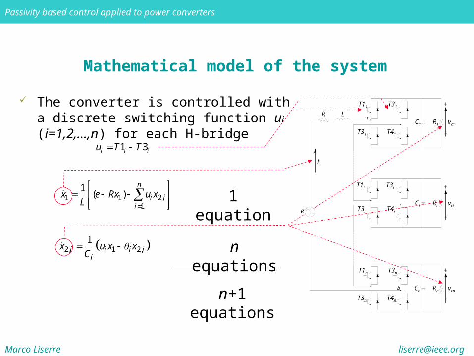
Mathematical model of the system
The converter is controlled with a discrete switching function ui (i=1,2,...,n) for each H-bridge
1 3i i iu T T
1 1 2,1
1( )
n
i ii
x e Rx u xL
2, 1 2,1
i i i ii
x u x xC
1 equation
n equations
n+1 equations
e
R L
+
_
T11 T31
T31 T41
R1
C1
vc1
+
_
T1i T3i
T3i T4i
Ri
Ci
vci
+
_
T1n T3n
T3n T4n
Rn
Cn
vcn
a
b
i
Marco Liserre [email protected]
Passivity based control applied to power converters
PBC of an H-bridge Since it is possible to control directly the grid current,
The d.c. voltage is controllable only indirectly, through an internal variable ξ2
1 1 21
( )z e Rz zL
average KVL on the a.c. side
*1 1 1
2
1DSe Rz Lz R z
predictive action
+
damping injection
average KCL on the d.c. side
differential eq. +
damping injection
Then it is necessary to estimate the d.c. load
2 1 21 z z zC *
2 1 2 21 ˆ
DPz G zC
2 1 2 2ˆ ˆ ˆ c c z
Marco Liserre [email protected]
Passivity based control applied to power converters
PBC of an n-H-bridge converter
It is not possible a simple extension of the PBC of one H-bridge active rectifier to n-bridge active rectifier
In fact the PBC of an H-bridge active rectifier needs one algebraic equation and one differential equation
Marco Liserre [email protected]
Passivity based control applied to power converters
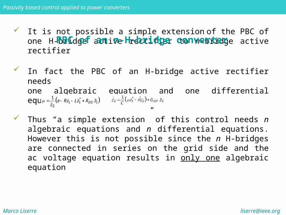
It is not possible a simple extension of the PBC of one H-bridge active rectifier to n-bridge active rectifier
In fact the PBC of an H-bridge active rectifier needs one algebraic equation and one differential equation
Thus “a simple extension” of this control needs n algebraic equations and n differential equations. However this is not possible since the n H-bridges are connected in series on the grid side and the ac voltage equation results in only one algebraic equation
PBC of an n-H-bridge converter
*1 1 1
2
1DSe Rz Lz R z
Marco Liserre [email protected]
Passivity based control applied to power converters
PBC of an n-H-bridge converter
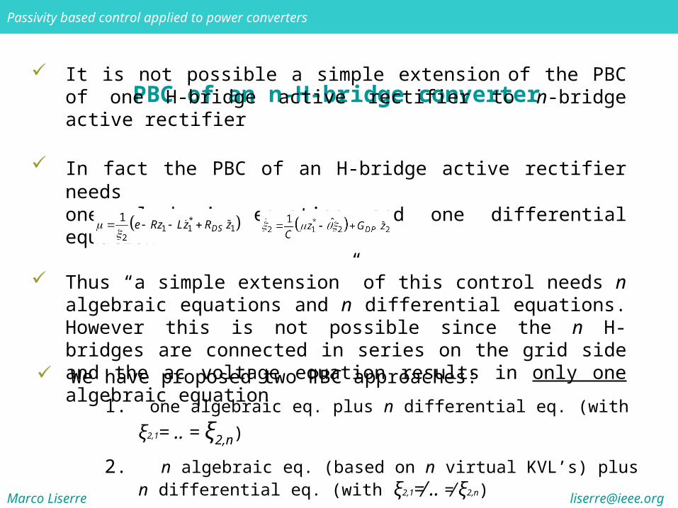
It is not possible a simple extension of the PBC of one H-bridge active rectifier to n-bridge active rectifier
In fact the PBC of an H-bridge active rectifier needs one algebraic equation and one differential equation
Thus “a simple extension” of this control needs n algebraic equations and n differential equations. However this is not possible since the n H-bridges are connected in series on the grid side and the ac voltage equation results in only one algebraic equation
We have proposed two PBC approaches:
1. one algebraic eq. plus n differential eq. (with ξ2,1= .. = ξ2,n)
2. n algebraic eq. (based on n virtual KVL’s) plus n differential eq. (with ξ2,1≠ .. ≠ ξ2,n)
*1 1 1
2
1DSe Rz Lz R z
Marco Liserre [email protected]
Passivity based control applied to power converters
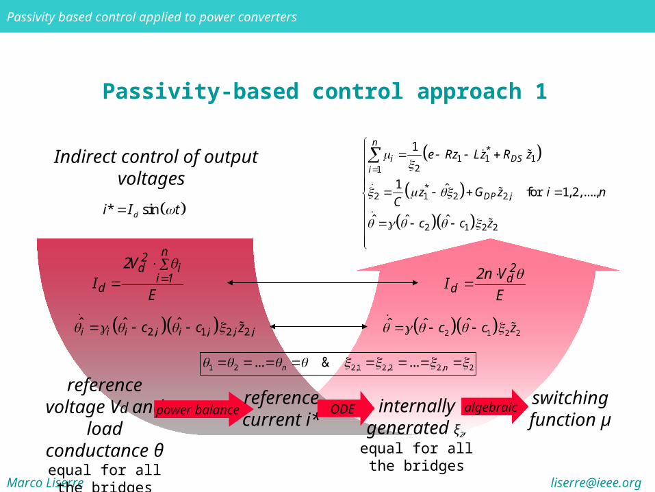
Passivity-based control approach 1
* sindi I t
E
V2I
n
1ii
2d
d
Indirect control of output voltages
E
Vn2I
2d
d
2 1 2 2ˆ ˆ ˆc c z
1 2 2,1 2,2 2, 2... & ...n n
reference voltage Vd and load
conductance θequal for all the bridges
power balancereference current i*
internally generated ξ2, equal
for all the bridges
ODEswitching function µ
algebraic
2, 1, 2, 2,ˆ ˆ ˆ i i i i i i i ic c z
*1 1 1
21
*2 1 2 2,
2 1 2 2
1
1 ˆ for 1, 2,....,
ˆ ˆ ˆ
n
i DSi
DP i
e Rz Lz R z
z G z i nC
c c z

Marco Liserre [email protected]
Passivity based control applied to power converters
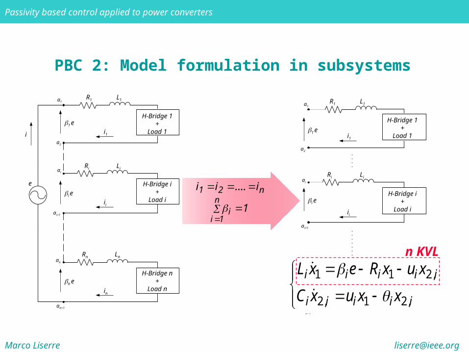
PBC 2: Model formulation in subsystems
n21 i....ii
1n
1ii
i1
e
H-Bridge 1+
Load 1 1 e
a2
n e
i
in
H-Bridge i+
Load i
H-Bridge n+
Load n
an
an+1
Rn Ln
ii
Ri
i e
ai+1
ai
Li
R1 a1 L1
i1
R1
1 e
a2
ai
i e
n e
ii
in
a1
ai+1
an
an+1
L1
Ri Li
Rn Ln
H-Bridge 1 +
Load 1
H-Bridge i +
Load i
H-Bridge n +
Load n
Marco Liserre [email protected]
Passivity based control applied to power converters
i1
R1
1 e
a2
ai
i e
n e
ii
in
a1
ai+1
an
an+1
L1
Ri Li
Rn Ln
H-Bridge 1 +
Load 1
H-Bridge i +
Load i
H-Bridge n +
Load n
PBC 2: Model formulation in subsystems
n21 i....ii
1n
1ii
i1
e
H-Bridge 1+
Load 1 1 e
a2
n e
i
in
H-Bridge i+
Load i
H-Bridge n+
Load n
an
an+1
Rn Ln
ii
Ri
i e
ai+1
ai
Li
R1 a1 L1
1 1 2,
2, 1 2,
i i i i i
i i i i i
L x e R x u x
C x u x x
n KVL
Marco Liserre [email protected]
Passivity based control applied to power converters
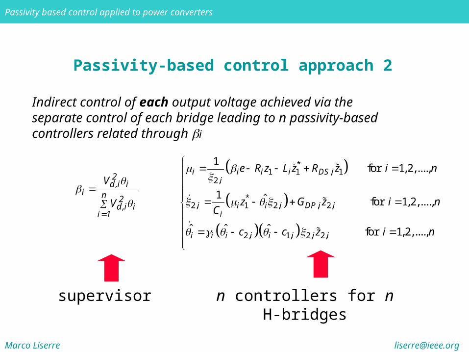
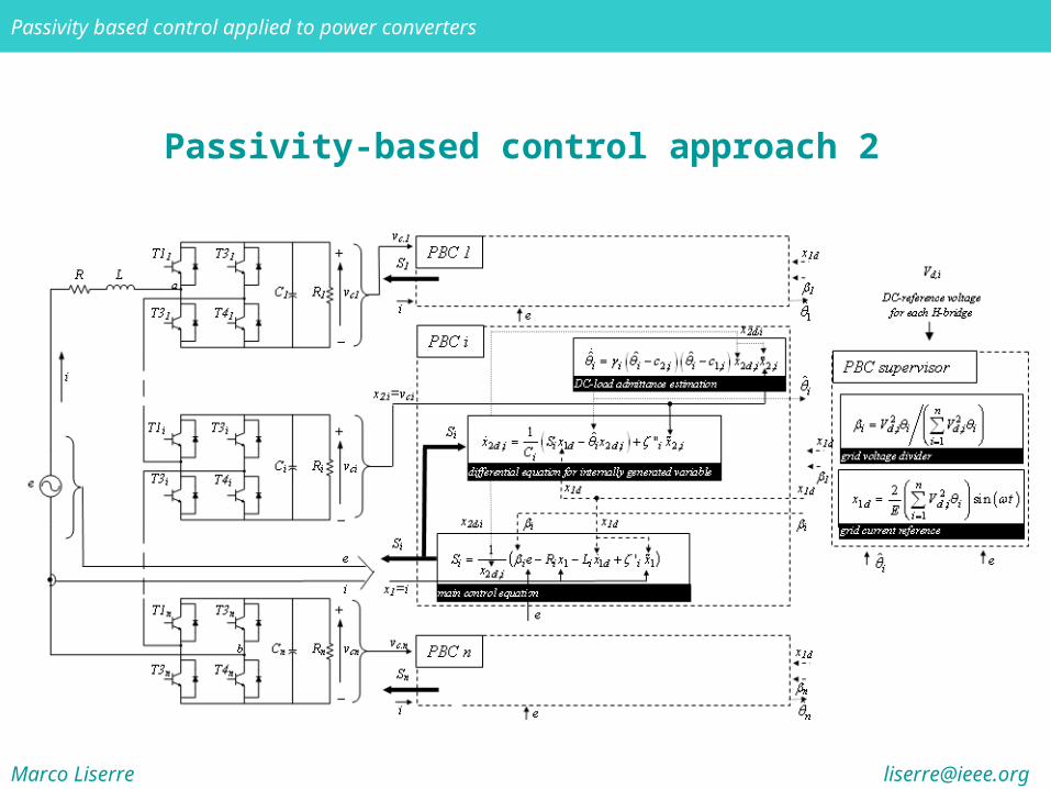
Passivity-based control approach 2
Indirect control of each output voltage achieved via the separate control of each bridge leading to n passivity-based controllers related through i
n
1ii
2i,d
i2
i,di
V
V
supervisor n controllers for n H-bridges
*1 1 , 1
2,
*2, 1 2, , 2,
2, 1, 2, 2,
1 for 1,2,....,
1 ˆ for 1, 2,....,
ˆ ˆ ˆ for 1, 2,....,
i i i i DS ii
i i i i DP i ii
i i i i i i i i
e R z L z R z i n
z G z i nC
c c z i n
Marco Liserre [email protected]
Passivity based control applied to power converters
Passivity-based control approach 2
only changing the parameters of the controllers
only changing the parameters of the controllers
Marco Liserre [email protected]
Passivity based control applied to power converters
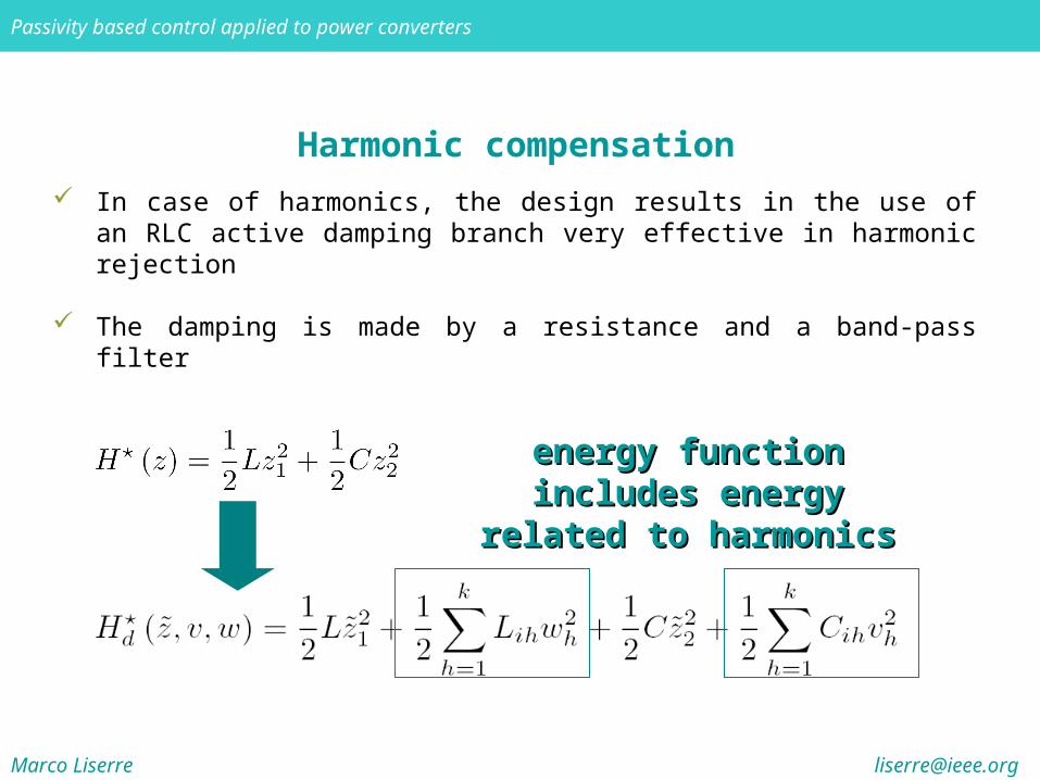
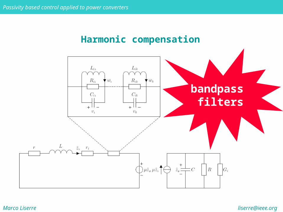
Harmonic compensation
energy function includes energy function includes energy related to harmonicsenergy related to harmonics
In case of harmonics, the design results in the use of an RLC active damping branch very effective in harmonic rejection
The damping is made by a resistance and a band-pass filter
Marco Liserre [email protected]
Passivity based control applied to power converters
Harmonic compensation
bandpass filters
Marco Liserre [email protected]
Passivity based control applied to power converters
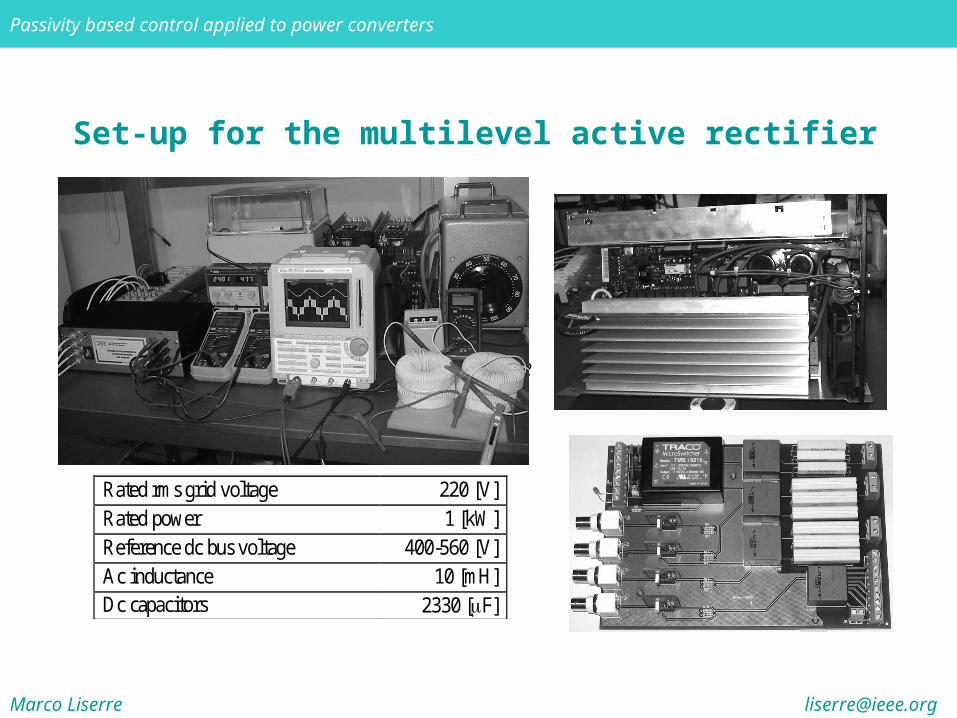
Set-up for the multilevel active rectifier
Rated rms grid voltage 220 [V] Rated power 1 [kW] Reference dc bus voltage 400-560 [V] Ac inductance 10 [mH] Dc capacitors 2330 [F]
CONTROLLER (Dspace card)
driving signal
& enable
GRID
VLT 5006
vc1
VLT 5006
vc2ie
Marco Liserre [email protected]
Passivity based control applied to power converters
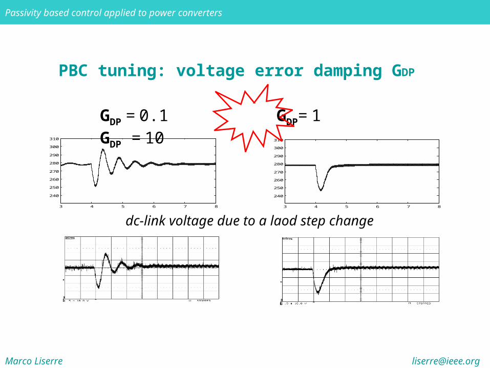
PBC tuning: voltage error damping GDP
3 4 5 6 7 8
240
250
260
270
280
290
300
310
3 4 5 6 7 8
240
250
260
270
280
290
300
310
GDP = 0.1 GDP= 1 GDP = 10
dc-link voltage due to a laod step change
Marco Liserre [email protected]
Passivity based control applied to power converters
0 2 4 6220
240
260
280
300
Time [s ]
Ca
pa
cito
r v
olt
ag
es
[V
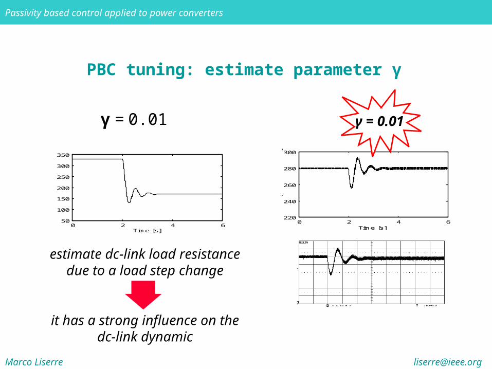
] γ = 0.01
PBC tuning: estimate parameter γ
γ = 0.01
0 2 4 650
100
150
200
250
300
350
Time [s ]
Esti
ma
te R
1=
R2
[O
hm
]
estimate dc-link load resistance due to a load step change
it has a strong influence on the dc-link dynamic
Marco Liserre [email protected]
Passivity based control applied to power converters
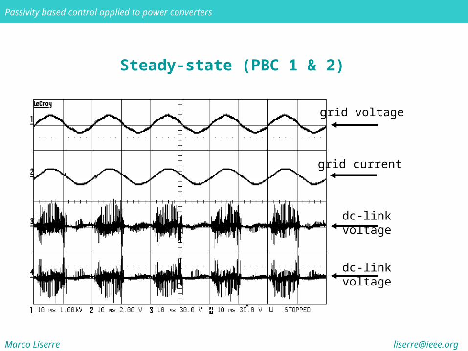
Steady-state (PBC 1 & 2)
grid voltage
grid current
dc-link voltage
dc-link voltage
Marco Liserre [email protected]
Passivity based control applied to power converters
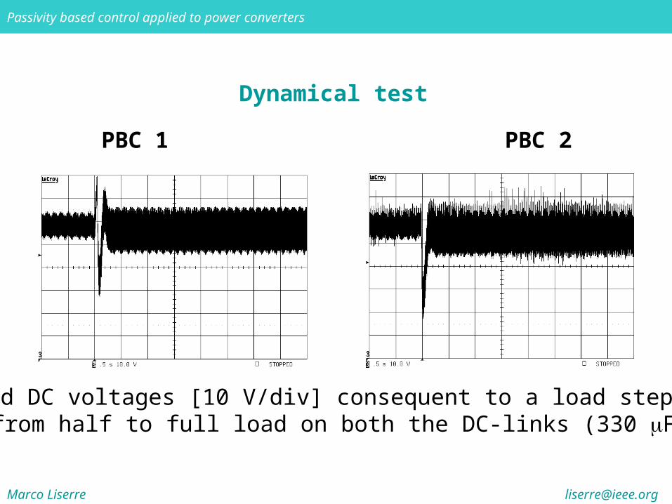
Dynamical test
Measured DC voltages [10 V/div] consequent to a load step change from half to full load on both the DC-links (330 F)
PBC 1 PBC 2
Marco Liserre [email protected]
Passivity based control applied to power converters
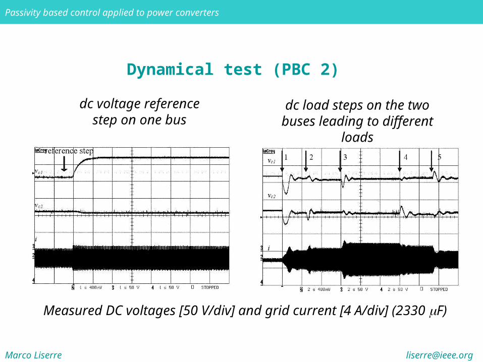
Dynamical test (PBC 2)
Measured DC voltages [50 V/div] and grid current [4 A/div] (2330 F)
dc voltage reference step on one bus
dc load steps on the two buses leading to different loads
Marco Liserre [email protected]
Passivity based control applied to power converters
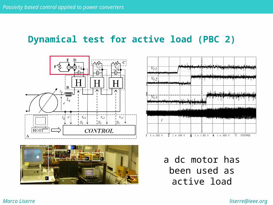
Dynamical test for active load (PBC 2)
a dc motor has been used as active load
Marco Liserre [email protected]
Passivity based control applied to power converters
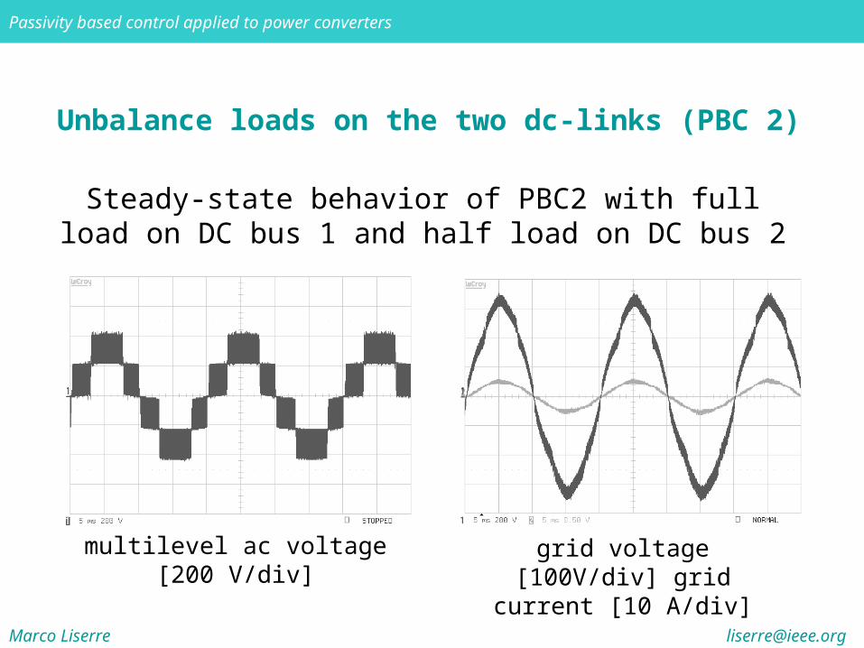
Unbalance loads on the two dc-links (PBC 2)
Steady-state behavior of PBC2 with full load on DC bus 1 and half load on DC bus 2
multilevel ac voltage [200 V/div] grid voltage [100V/div] grid current [10 A/div]
Marco Liserre [email protected]
Passivity based control applied to power converters
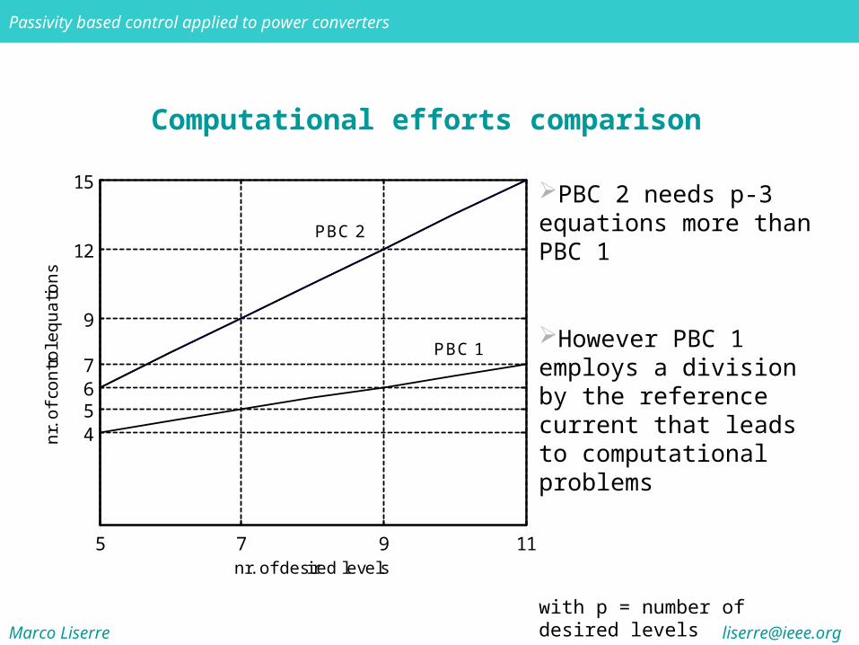
Computational efforts comparison
5 7 9 11
4567
9
12
15
nr. of de sire d le ve ls
nr.
of
con
tro
l eq
ua
tion
s
P BC 2
P BC 1
PBC 2 needs p-3 equations more than PBC 1
However PBC 1 employs a division by the reference current that leads to computational problems
with p = number of desired levels

Marco Liserre [email protected]
Passivity based control applied to power converters
Harmonic compensation
R-dampingR-damping
RLC-dampingRLC-damping
Marco Liserre [email protected]
Passivity based control applied to power converters
Conclusions
Passivity-based theory offers a straightforward approach to design controllers without linearazing the system: physical and intuitive representation of the control problem design method to make the system Lyapunov-stable feedback decomposition useful for electromechanical systems
Eulero-Lagrange formulation more suitable for electrical motors
Brayton-Moser formulation more suitable for power converters (tuning procedure)
Optimal results can be obtained with RLC damping of harmonics (similar to those obtained with generalized integrators – resonant controllers – linear approach)