PASSENGER ELEVATORS - MITSUBISHI ELECTRIC...
15
PASSENGER ELEVATORS
Transcript of PASSENGER ELEVATORS - MITSUBISHI ELECTRIC...

C-CL1-3-C9113-B INA-1310 Printed in Japan (MDOC)
Eco Changes is the Mitsubishi Electric Group’s environmental statement,and expresses the Group’s stance on environmental management. Through a wide range of businesses, we are helping contribute to the realization of a sustainable society.
Visit our website at:http://www.mitsubishielectric.com/elevator/
PASSENGER ELEVATORS
Revised publication effective Oct. 2013.Superseding publication of C-CL1-3-C9113-A Mar. 2013.
Specifications are subject to change without notice.
2013
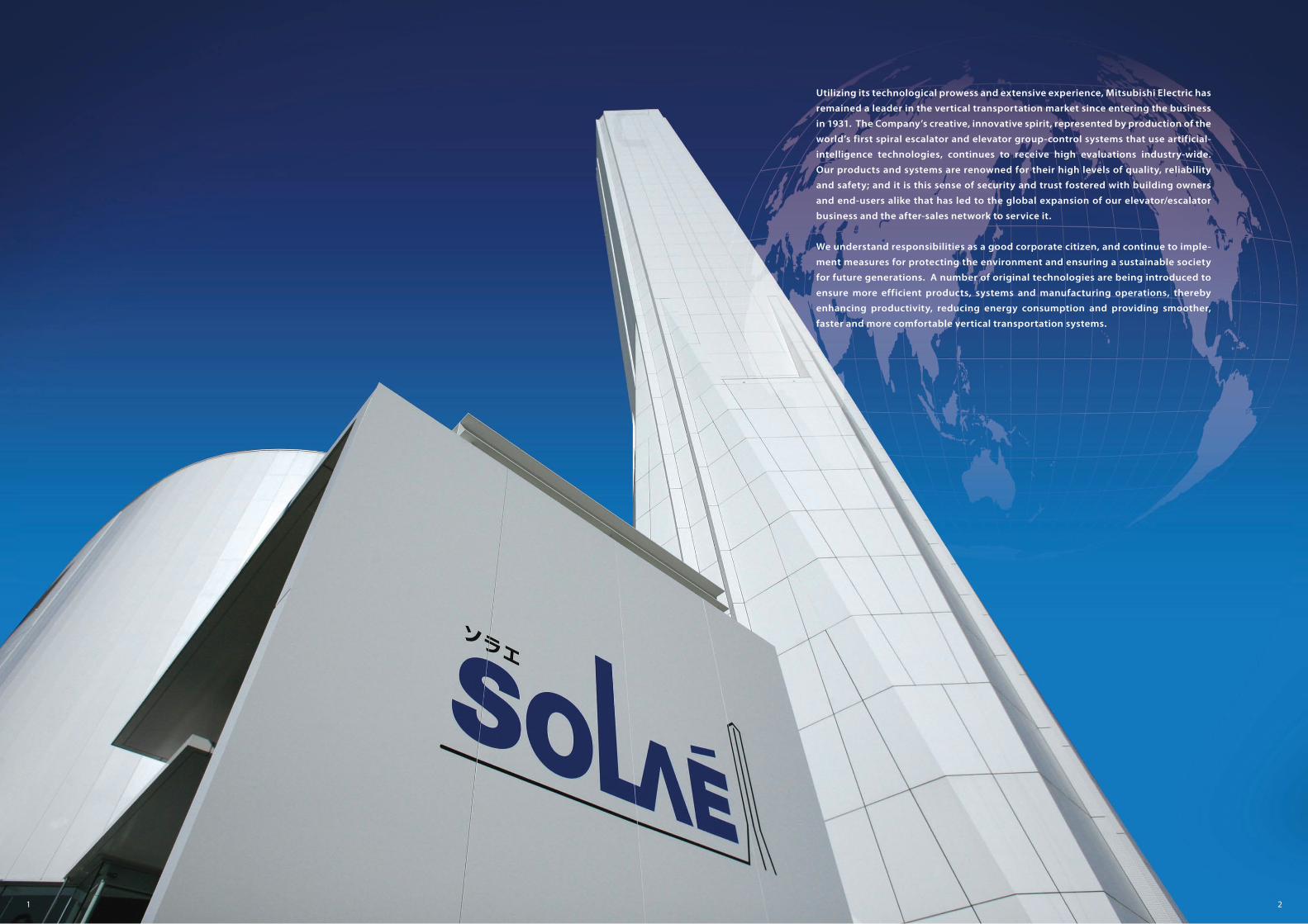
Utilizing its technological prowess and extensive experience, Mitsubishi Electric has
remained a leader in the vertical transportation market since entering the business
in 1931. The Company’s creative, innovative spirit, represented by production of the
world’s first spiral escalator and elevator group-control systems that use artificial-
intelligence technologies, continues to receive high evaluations industry-wide.
Our products and systems are renowned for their high levels of quality, reliability
and safety; and it is this sense of security and trust fostered with building owners
and end-users alike that has led to the global expansion of our elevator/escalator
business and the after-sales network to service it.
We understand responsibilities as a good corporate citizen, and continue to imple-
ment measures for protecting the environment and ensuring a sustainable society
for future generations. A number of original technologies are being introduced to
ensure more efficient products, systems and manufacturing operations, thereby
enhancing productivity, reducing energy consumption and providing smoother,
faster and more comfortable vertical transportation systems.
21
Mitsubishi Electric elevators, escalators and building management systems are always evolving, helping achieve our goal of being the No.1 brand in quality.In order to satisfy customers in all aspects of comfort, efficiency and safety while realizing a sustainable society, quality must be of the highest level in all products and business activities, while priority is place on consideration for the environment. As the times change, Mitsubishi Electric promises to utilize the collective strengths of its advanced and environmental technologies to offer its customers safe and reliable products while contributing to society.
Application
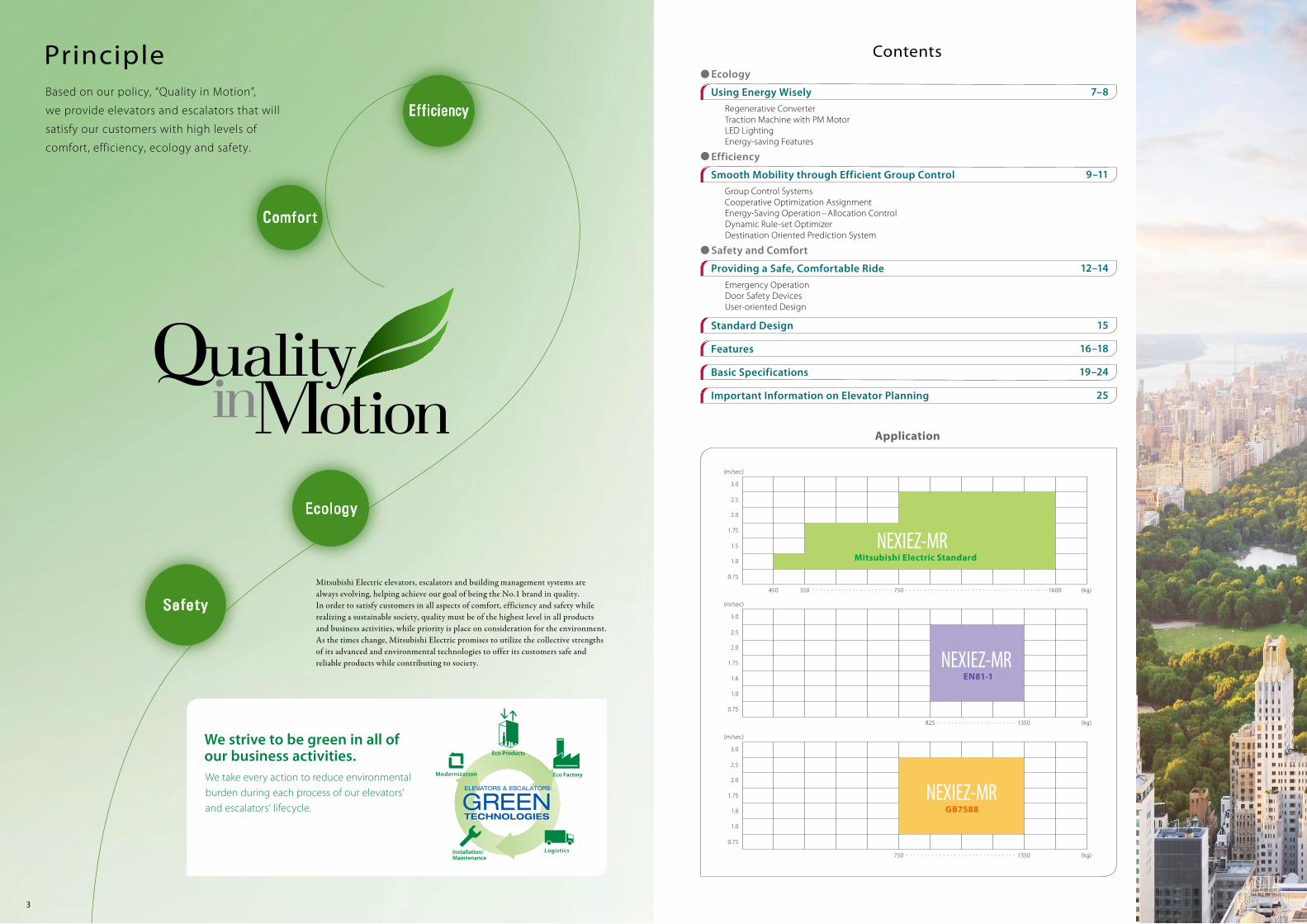
Based on our policy, “Quality in Motion”,
we provide elevators and escalators that will
satisfy our customers with high levels of
comfort, efficiency, ecology and safety.
Principle Contents
3
We strive to be green in all of our business activities.We take every action to reduce environmental burden during each process of our elevators’ and escalators’ lifecycle.
Ecology
Regenerative ConverterTraction Machine with PM MotorLED LightingEnergy-saving Features
Efficiency
Group Control SystemsCooperative Optimization AssignmentEnergy-Saving Operation–Allocation ControlDynamic Rule-set OptimizerDestination Oriented Prediction System
Safety and Comfort
Emergency OperationDoor Safety DevicesUser-oriented Design
750 . . . . . . . . . . . . . . . . . . . . . . . . . . . . . . 1350 (kg)
(m/sec)
2.0
2.5
3.0
1.75
1.6
1.0
0.75
GB7588
825 . . . . . . . . . . . . . . . . . . . . . . 1350 (kg)
(m/sec)
2.0
2.5
3.0
1.75
1.6
1.0
0.75
EN81-1
450 550 750 . . . . . . . . . . . . . . . . . . . . . . . . . . . . . . . . . . . . . . .. . . . . . . . . . . . . . . . . . . . . . 1600 (kg)
(m/sec)
2.0
2.5
3.0
1.75
1.5
1.0
0.75
Mitsubishi Electric Standard
Using Energy Wisely 7–8
Smooth Mobility through Efficient Group Control 9–11
Providing a Safe, Comfortable Ride 12–14
Standard Design 15
Features 16–18
Basic Specifications 19–24
Important Information on Elevator Planning 25
4
5
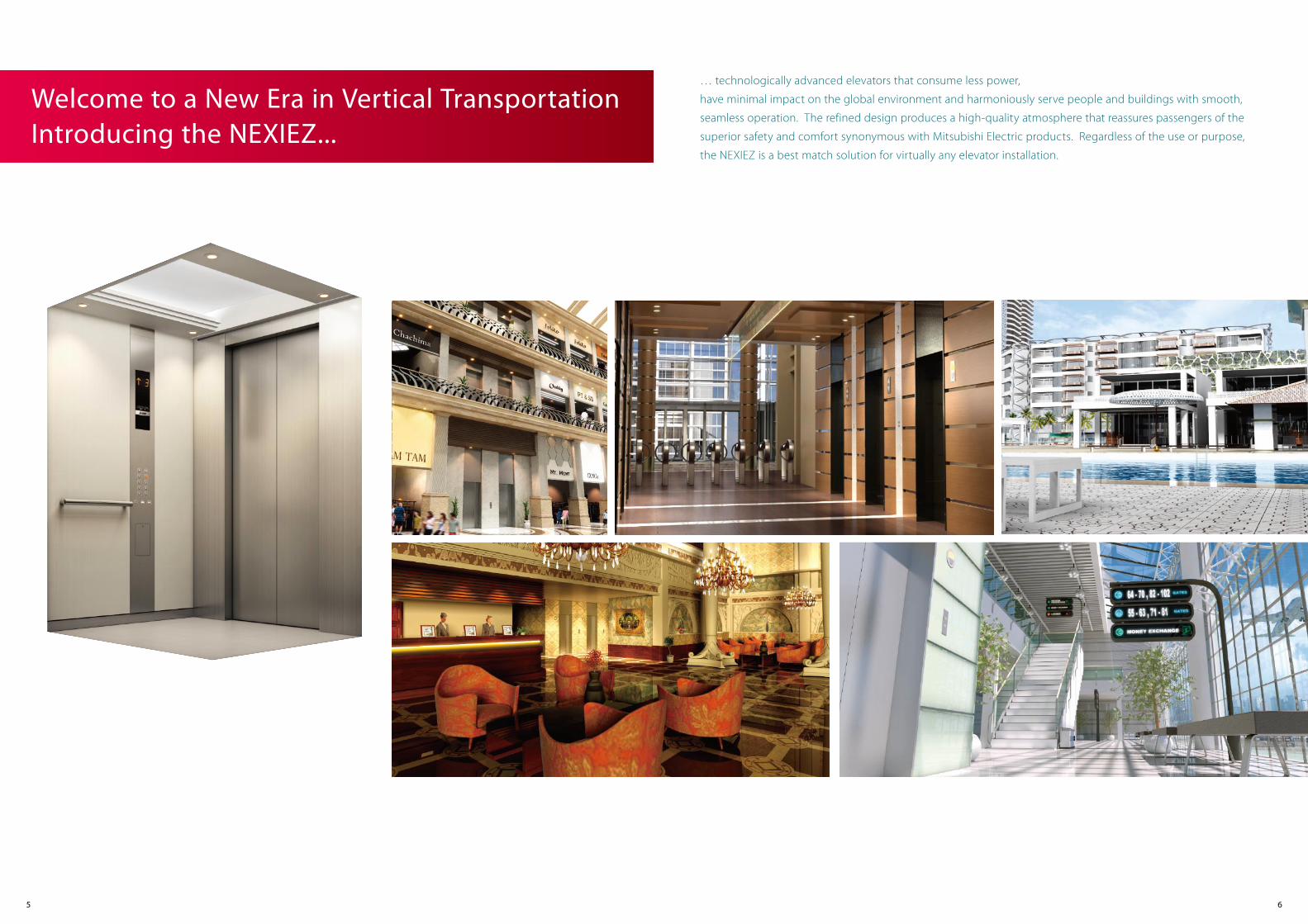
… technologically advanced elevators that consume less power,
have minimal impact on the global environment and harmoniously serve people and buildings with smooth,
seamless operation. The refined design produces a high-quality atmosphere that reassures passengers of the
superior safety and comfort synonymous with Mitsubishi Electric products. Regardless of the use or purpose,
the NEXIEZ is a best match solution for virtually any elevator installation.
Welcome to a New Era in Vertical TransportationIntroducing the NEXIEZ...
6
7
Ecology
Regenerative Converter (PCNV) (Optional)Elevators usually travel using power from a power supply (powered operation); however, when they travel down with a heavy car load or up with a light car load (regenerative operation), the traction machine functions as a power generator. Although the power generated during traction machine operation is usually dissipated as heat, the regenerative converter transmits the power back to the distribution transformer and feeds into the electrical network in the building along with electricity from the power supply. Compared to the same type of elevator without a regenerative converter, this system provides an energy-saving effect of up to 35%. (Reduction in CO2 emissions: 1400 kg/year) In addition, the Regenerative Converter has the effect of decreasing harmonic currents.
Powered operation
Distributiontransformer Power supply
Motor
Regenerativeconverter
Control panel
Distributiontransformer
Regenerative operation
Power supply
Motor
RegenerativeconverterControl panel
The joint-lapped core built in the PM motor of the traction machine features flexible joints. The iron core can be like a hinge, which allows coils to be wound around the core more densely, resulting in improved motor efficiency and compactness. High-density magnetic field is produced, enabling lower use of energy and resources and reduced CO2 emissions.In addition, we have adopted a 2:1 (single-wrap) roping system, which lessens load on the traction machine, and allows further reductions in traction machine size.
Ceiling: L210S LED downlights (yellow-orange)
Gearless tractionmachine with PM motor
Traction Machine with PM Motor(PM motor: Permanent magnet motor)
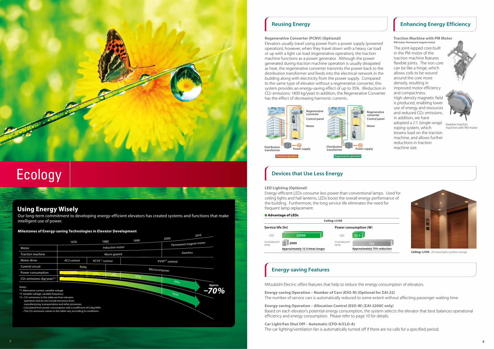
Our long-term commitment to developing energy-efficient elevators has created systems and functions that make intelligent use of power.
Milestones of Energy-saving Technologies in Elevator Development
Traction machine
Motor drive
Control circuit
Power consumption
CO2 emissions (kg/year)*3
Motor Permanent magnet motor
Gearless
20102000
199019801970
VVVF controlACVV *1 controlAC2 control
MicrocomputerRelay
30%
37%74%93% 100%
1610
*2
Worm geared
Induction motor
Notes:*1: Alternative current, variable voltage*2: Variable voltage, variable frequency*3: • CO2 emissions in this table are from elevator operation and do not include emissions from manufacturing, transportation and other processes. • Calculated from power consumption with a coefficient of 0.6kg/kWh. • The CO2 emissions values in this table vary according to conditions.
–70%Approx.
Using Energy Wisely
LED Lighting (Optional)Energy-efficient LEDs consume less power than conventional lamps. Used for ceiling lights and hall lanterns, LEDs boost the overall energy performance of the building. Furthermore, the long service life eliminates the need for frequent lamp replacement.
Mitsubishi Electric offers features that help to reduce the energy consumption of elevators.
Energy-saving Operation – Number of Cars (ESO-N) (Optional for ΣAI-22)The number of service cars is automatically reduced to some extent without affecting passenger waiting time.
Energy-saving Operation – Allocation Control (ESO-W) (ΣAI-2200C only)Based on each elevator’s potential energy consumption, the system selects the elevator that best balances operational efficiency and energy consumption. Please refer to page 10 for details.
Car Light/Fan Shut Off – Automatic (CFO-A/CLO-A)The car lighting/ventilation fan is automatically turned off if there are no calls for a specified period.
8
Ceiling: L210S
● Advantage of LEDs
Service life (hr) Power consumption (W)
Approximately 12.5 times longer Approximately 75% reduction
Reusing Energy
Devices that Use Less Energy
Energy-saving Features
Enhancing Energy Efficiency
LED
Incandescentlamp
25000
2000
LED
Incandescentlamp
32.5
132
9 10
Efficiency
Group Control Systems: ΣAI-22 and ΣAI-2200CΣAI-22 and ΣAI-2200C control multiple elevators optimally according to the building size.
makes a big difference in preventing congestion at a lobby floor and reducing long waits.
Smooth Mobility through Efficient Group ControlWhen a building is expected to have heavy traffic, optimum car allocation suited for every condition
Improving of traffic efficiency can alleviate thepassengers’ irritation. Applying the new allocationalgorithm, the average waiting time and long waitsare reduced.
Performance
0
5
10
15
20
25
30
Morning uppeak
Lunchtime Eveningdown peak
Daytime0
2
4
6
8
10
Morning uppeak
Lunchtime Eveningdown peak
Daytime
Average waiting time Long-wait rate (60 seconds or longer)
ΣAI-2200C (New)AI-2100N (Conventional system)
(sec) (%)
Improved: Max. 30% Improved: Max. 60%
Initial conditions: non-peak periodCar A: Parked at the 3rd floor
Car B: About to leave the 9th floor with several passengers
Car C: Parked at the 9th floor.
Car D: Parked at the 1st floorUnder the conditions above, when a hall call is registered at the 6th floor to go to the 1st floor, waiting time and traveling distance will be the same regardless of whether car A, B or C responds to the call.
In response to the call, the cars will operate in the following ways:Car A will travel up with no passengers and then down with only one passenger (requires more energy than car B).Car B will travel down with more passengers than car A (requires the least energy).Car C will travel down with no passengers and then down with only one passenger (requires the most energy).
Car selectionDuring non-peak hours when energy efficiency is prioritized, car B is selected.
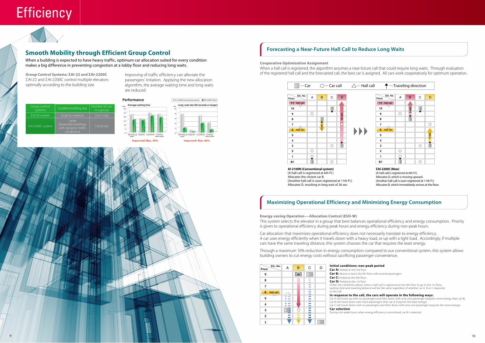
Forecasting a Near-Future Hall Call to Reduce Long Waits
Cooperative Optimization AssignmentWhen a hall call is registered, the algorithm assumes a near-future call that could require long waits. Through evaluation of the registered hall call and the forecasted call, the best car is assigned. All cars work cooperatively for optimum operation.
AI-2100N (Conventional system)[A hall call is registered at 6th Fl.]Allocates the closest car B.[Another hall call is soon registered at 11th Fl.]Allocates D, resulting in long wait of 26 sec.
ΣAI-2200C (New)[A hall call is registered at 6th Fl.]Allocates D, which is moving upward.[Another hall call is soon registered at 11th Fl.]Allocates B, which immediately arrives at the floor.
Ele. No.
Maximizing Operational Efficiency and Minimizing Energy Consumption
Energy-saving Operation — Allocation Control (ESO-W)This system selects the elevator in a group that best balances operational efficiency and energy consumption. Priority is given to operational efficiency during peak hours and energy efficiency during non-peak hours.
Car allocation that maximizes operational efficiency does not necessarily translate to energy efficiency. A car uses energy efficiently when it travels down with a heavy load, or up with a light load. Accordingly, if multiple cars have the same traveling distance, this system chooses the car that requires the least energy.
Through a maximum 10% reduction in energy consumption compared to our conventional system, this system allows building owners to cut energy costs without sacrificing passenger convenience.
9
1
2
3
4
5
7
8
Group controlsystems
ΣAI-22 system
ΣAI-2200C system
Suitable building size
Small to medium
Large(Especially buildingswith dynamic traffic
conditions)
Number of carsin a group
3 to 4 cars
3 to 8 cars
Hall call Traveling directionCar callCar
Ele. No.
Ele. No.
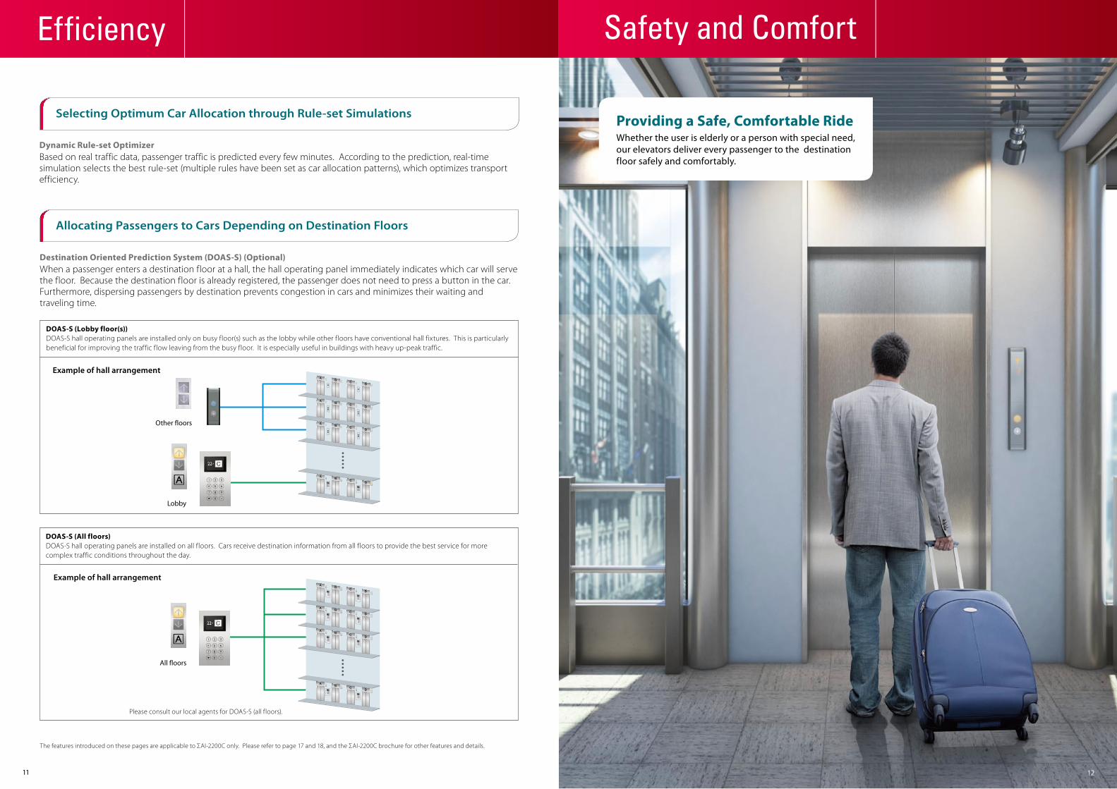
Dynamic Rule-set OptimizerBased on real traffic data, passenger traffic is predicted every few minutes. According to the prediction, real-time simulation selects the best rule-set (multiple rules have been set as car allocation patterns), which optimizes transport efficiency.
Destination Oriented Prediction System (DOAS-S) (Optional)When a passenger enters a destination floor at a hall, the hall operating panel immediately indicates which car will serve the floor. Because the destination floor is already registered, the passenger does not need to press a button in the car. Furthermore, dispersing passengers by destination prevents congestion in cars and minimizes their waiting and traveling time.
DOAS-S (Lobby floor(s))DOAS-S hall operating panels are installed only on busy floor(s) such as the lobby while other floors have conventional hall fixtures. This is particularly beneficial for improving the traffic flow leaving from the busy floor. It is especially useful in buildings with heavy up-peak traffic.
DOAS-S (All floors)DOAS-S hall operating panels are installed on all floors. Cars receive destination information from all floors to provide the best service for more complex traffic conditions throughout the day.
The features introduced on these pages are applicable to ΣAI-2200C only. Please refer to page 17 and 18, and the ΣAI-2200C brochure for other features and details.
11
Other floors
Lobby
Example of hall arrangement
All floors
Example of hall arrangement
Please consult our local agents for DOAS-S (all floors).
Selecting Optimum Car Allocation through Rule-set Simulations
Allocating Passengers to Cars Depending on Destination Floors
12
Efficiency Safety and Comfort
Whether the user is elderly or a person with special need, our elevators deliver every passenger to the destination floor safely and comfortably.
Providing a Safe, Comfortable Ride
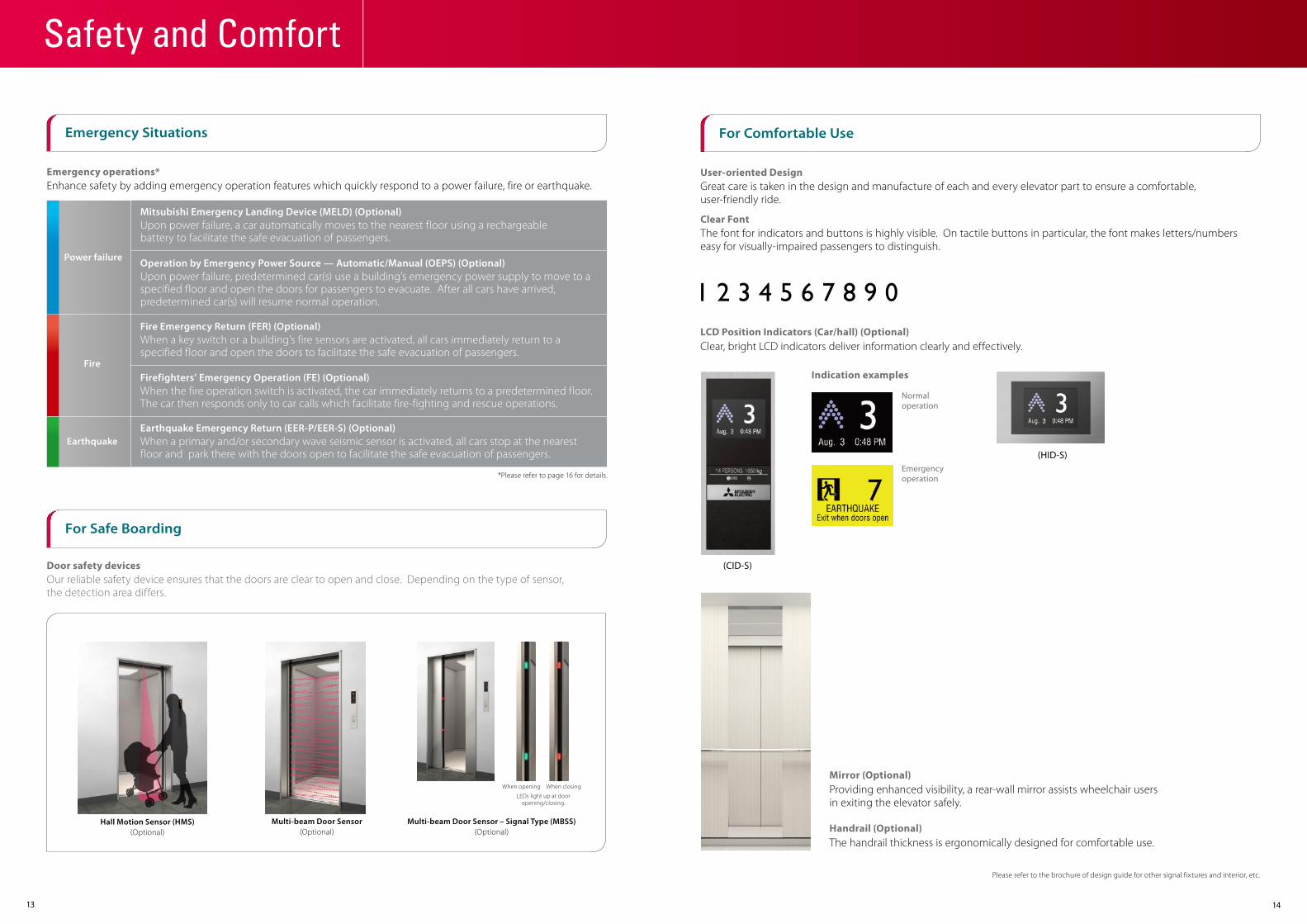
Emergency operations*Enhance safety by adding emergency operation features which quickly respond to a power failure, fire or earthquake.
Door safety devicesOur reliable safety device ensures that the doors are clear to open and close. Depending on the type of sensor, the detection area differs.
Hall Motion Sensor (HMS)(Optional)
13
Multi-beam Door Sensor – Signal Type (MBSS)(Optional)
Multi-beam Door Sensor(Optional)
LEDs light up at dooropening/closing.
When opening When closing
For Safe Boarding
Emergency Situations
14
Power failure
Mitsubishi Emergency Landing Device (MELD) (Optional)Upon power failure, a car automatically moves to the nearest floor using a rechargeable battery to facilitate the safe evacuation of passengers.
Operation by Emergency Power Source — Automatic/Manual (OEPS) (Optional)Upon power failure, predetermined car(s) use a building’s emergency power supply to move to aspecified floor and open the doors for passengers to evacuate. After all cars have arrived, predetermined car(s) will resume normal operation.
Fire
Fire Emergency Return (FER) (Optional)When a key switch or a building’s fire sensors are activated, all cars immediately return to a specified floor and open the doors to facilitate the safe evacuation of passengers.
Firefighters’ Emergency Operation (FE) (Optional)When the fire operation switch is activated, the car immediately returns to a predetermined floor.The car then responds only to car calls which facilitate fire-fighting and rescue operations.
EarthquakeEarthquake Emergency Return (EER-P/EER-S) (Optional)When a primary and/or secondary wave seismic sensor is activated, all cars stop at the nearestfloor and park there with the doors open to facilitate the safe evacuation of passengers.
*Please refer to page 16 for details.
Safety and Comfort
User-oriented DesignGreat care is taken in the design and manufacture of each and every elevator part to ensure a comfortable, user-friendly ride.
Clear FontThe font for indicators and buttons is highly visible. On tactile buttons in particular, the font makes letters/numbers easy for visually-impaired passengers to distinguish.
LCD Position Indicators (Car/hall) (Optional)Clear, bright LCD indicators deliver information clearly and effectively.
Normal operation
Indication examples
Emergency operation
Mirror (Optional)Providing enhanced visibility, a rear-wall mirror assists wheelchair users in exiting the elevator safely.
Handrail (Optional)The handrail thickness is ergonomically designed for comfortable use.
For Comfortable Use
Please refer to the brochure of design guide for other signal fixtures and interior, etc.
(CID-S)
(HID-S)

1615
Features (1/2)Standard Design
Notes:*1: Maximum number of floors: 22 floors*2: Some letters of the alphabets are not available. Please consult our local agents for details.
Actual colors may differ slightly from those shown.Please refer to the design guide for details and other designs.
SUS-HLSUS-HLSUS-HLSUS-HLAluminumPR803CBV1-C760 Ceiling: Painted steel sheet (Y033)
with a milky white resin lighting coverLighting: Central lighting
WallsTransom panelDoorsFront return panelsKickplateFlooringCar operating panel
Car Design Example
Hall Design Example
Car
Hall
Segment LED indicatorsTactile button with yellow-orange lighting
Car operating panel
Hall position indicators and buttons
CBV1-C760*1
*2
*2
JambDoorsHall position indicatorand button
SUS-HLSUS-HL
PIV1-A710N
Narrow Jamb: E-102
Ceiling: S00
Boxless
Segment LED indicatorsTactile button with yellow-orange lighting
PIV1-A710N PIV1-A720N
Metal-like resin faceplates
For front return panel
Yellow-orange lighting
Tactile button
Boxless Boxless
Feature Description 3C to 8CΣAI-2200C
3C to 4CΣAI-22
1C-2BC
2C-2BC
■ EMERGENCY OPERATIONS AND FEATURESUpon power failure, a car equipped with this function automatically moves and stops at the nearest floor using a rechargeable battery, and the doors open to facilitate the safe evacuation of passengers. (Maximum allowable floor-to-floor distance is 10 meters.)
Mitsubishi Emergency LandingDevice (MELD)
Upon power failure, predetermined car(s) use a building’s emergency power supply to move to a specified floor, where the doors then open to facilitate the safe evacuation of passengers. After all cars have arrived, predetermined car(s) will resume normal operation.
Operation by Emergency Power Source — Automatic/Manual (OEPS)
Upon activation of a key switch or a building’s fire sensors, all calls are canceled, all cars immediately return to a specified evacuation floor and the doors open to facilitate the safe evacuation of passengers.
Fire Emergency Return (FER)
During a fire, when the fire operation switch is activated, the car calls of a specified car and all hall calls are canceled and the car immediately returns to a predetermined floor. The car then responds only to car calls which facilitate fire-fighting and rescue operations.
Firefighters’ Emergency Operation (FE)
Upon activation of primary and/or secondary wave seismic sensors, all cars stop at the nearest floor, and park there with the doors open to facilitate the safe evacuation of passengers.
Earthquake Emergency Return(EER-P/EER-S)
Each elevator’s status and operation can be remotely monitored and controlled through a panel installed in a building’s supervisory room, etc.
Supervisory Panel (WP)
MelEye (WP-W)Mitsubishi Elevators & Escalators Monitoring and Control System
Each elevator’s status and operation can be monitored and controlled using an advanced Web-based technology which provides an interface through personal computers. Special optional features such as preparation of traffic statistics and analysis are also available.
Car lighting which turns on immediately when power fails, providing a minimum level of lighting within the car. (Choice of dry-cell battery or trickle-charge battery.)
Emergency Car Lighting (ECL)
#1#1
■ DOOR OPERATION FEATURESFailure of non-contact door sensors is checked automatically, and if a problem is diagnosed, the door-close timing is delayed and the closing speed is reduced to maintain elevator service and ensure passenger safety.
Door Sensor Self-diagnosis (DODA)
Door load on each floor, which can depend on the type of hall door, is monitored to adjust the door speed, thereby making the door speed consistent throughout all floors.
Automatic Door Speed Control(DSAC)
The time doors are open will automatically be adjusted, depending on whether the stop was called from the hall or the car, to allow smooth boarding of passengers or loading of baggage.
Automatic Door-open TimeAdjustment (DOT)
Closing doors can be reopened by pressing the hall button corresponding to the traveling direction of the car.
Reopen with Hall Button (ROHB)
Should an obstacle prevent the doors from closing, the doors will repeatedly open and close until the obstacle is cleared from the doorway.
Repeated Door-close (RDC)
When the button inside a car is pressed, the doors will remain open longer to allow loading and unloading of baggage, a stretcher, etc.
Extended Door-open Button(DKO-TB)
When excessive door load has been detected while opening or closing, the doors immediately reverse.
Door Load Detector (DLD)
Safety Door Edge (SDE)
Safety Ray (SR) 1-Beam
2-Beam
Electronic Doorman (EDM) Door open time is minimized using safety ray(s) or multi-beam door sensors that detect passengers boarding or exiting.
Door Nudging Feature— With Buzzer (NDG)
A buzzer sounds and the doors slowly close when they have remained open for longer than the preset period. With AAN-B or AAN-G, a beep and voice guidance sound instead of the buzzer.
One side
Both sides(CO doors only)
Sensitive door edge(s) detect passengers or objects during door closing.(Cannot be combined with the MBSS feature.)
One or two infrared-light beams cover the full width of the doors as they close to detect passengers or objects. (Cannot be combined with the multi-beam door sensor or MBSS feature.)
Multi-beam Door Sensor Multiple infrared-light beams cover a door height of approximately 1800mm to detect passengers or objects as the doors close. (Cannot be combined with the SR or MBSS feature.) Please refer to page 13.
Hall Motion Sensor (HMS) Infrared-light is used to scan a 3D area near the open doors to detect passengers or objects. Please refer to page 13.
Multi-beam Door Sensor— Signal Type (MBSS)
Multiple infrared-light beams cover a door height of approximately 1800mm to detect passengers or objects as the doors close. Additionally, LED lights on the door edge will indicate the door opening/closing and the presence of an obstacle between the doors. (Cannot be combined with any of the following features: SDE, SR or multi-beam door sensor.) Please refer to page 13.
Notes: • 1C-2BC (1-car selective collective) - Standard, 2C-2BC (2-car group control system) - Optional, ΣAI-22 (3- and 4-car group control system) - Optional, ΣAI-2200C (3- to 8-car group control system) - Optional • = Standard = Optional = Not applicable • #1: Please consult our local agents for the production terms, etc.

A hall lantern, which corresponds to a car’s service direction, flashes to indicate that the car will soon arrive.
Flashing Hall Lantern (FHL)
Forced Floor Stop (FFS) All cars in a bank automatically make a stop at a predetermined floor on every trip without being called.
Main Floor Parking (MFP) An available car always parks on the main (lobby) floor with the doors open/closed (China only).
Energy-saving Operation— Number of Cars (ESO-N)
To save energy, the number of service cars is automatically reduced to some extent, but not so much that it adversely affects passenger waiting time. Please refer to page 8.
The timing of car allocation and the number of cars to be allocated to floors where meeting rooms or ballrooms exist and the traffic intensifies for short periods of time are controlled according to the detected traffic density data for those floors.
Congested-floor Service (CFS)
Hall buttons and the cars called by each button can be divided into several groups for independent group control operation to serve special needs or different floors.
Bank-separation Operation (BSO)
A specified car is withdrawn from group control operation for VIP service operation. When activated, the car responds only to existing car calls, moves to a specified floor and parks there with the doors open. The car will then respond only to car calls.
VIP Operation (VIP-S)
During the first half of lunchtime, calls for a restaurant floor are served with higher priority, and during the latter half, the number of cars allocated to the restaurant floor, the allocation timing for each car and the door opening and closing timing are all controlled based on predicted data.
Lunchtime Service (LTS)
This feature is effective for buildings with two main (lobby) floors. The floor designated as the “main floor” in a group control operation can be changed as necessary using a manual switch.
Main Floor Changeover Operation (TFS)
When traffic is light, empty or lightly-loaded cars are given higher priority to respond to hall calls in order to minimize passenger travel time. (Cannot be combined with hall position indicators.)
Light-load Car Priority Service (UCPS)
Special cars, such as observation elevators and elevators with basement service, are given higher priority to respond to hall calls. (Cannot be combined with hall position indicators.)
Special Car Priority Service (SCPS)
#1
#1
#1
#1
Feature Description 3C to 8CΣAI-2200C
3C to 4CΣAI-22
1C-2BC
2C-2BC Feature Description 3C to 8C
ΣAI-2200C3C to 4CΣAI-22
1C-2BC
2C-2BC
1817
■ OPERATIONAL AND SERVICE FEATURES
An operation by car controllers which automatically maintains elevator operation in the event that a microprocessor or transmission line in the group controller has failed.
Backup Operation for Group Control Microprocessor (GCBK)
With a key switch on the supervisory panel, etc., a car can be called to a specified floor after responding to all car calls, and then automatically be taken out of service.
Out-of-service-remote (RCS)
To enhance security, car calls for desired floors can be registered only by entering secret codes using the car buttons on the car operating panel. This function is automatically deactivated during emergency operation.
Secret Call Service (SCS-B)
To enhance security, car calls for desired floors can be registered only by placing a card over a card reader. This function is automatically deactivated during emergency operation.
Non-service TemporaryRelease for Car Call— Card Reader Type (NSCR-C)
To enhance security, service to specific floors can be disabled using the car operating panel. This function is automatically deactivated during emergency operation.
Non-service to Specific Floors— Car Button Type (NS-CB)
To enhance security, service to specific floors can be disabled using a manual or timer switch. This function is automatically deactivated during emergency operation.
Non-service to Specific Floors— Switch/Timer Type (NS/NS-T)
For maintenance or energy-saving measures, a car can be taken out of service temporarily with a key switch (with or without a timer) mounted in a specified hall.
Using a key switch on the supervisory panel, a car can be withdrawn from group control operation and called to a specified floor. The car will park on that floor with the doors open, and not accept any calls until independent operations begin.
Return Operation (RET)
Exclusive operation where an elevator can be operated using the buttons and switches located in the car operating panel, allowing smooth boarding of passengers or loading of baggage.
Attendant Service (AS)
Exclusive operation where a car is withdrawn from group control operation for independent use, such as maintenance or repair, and responds only to car calls.
Independent Service (IND)
If a car has stopped between floors due to some equipment malfunction, the controller checks the cause, and if it is considered safe to move the car, the car will move to the nearest floor at a low speed and the doors will open.
Safe Landing (SFL)
If the elevator doors do not open fully at a destination floor, the doors close, and the car automatically moves to the next or nearest floor where the doors will open.
Next Landing (NXL)
A car which is experiencing trouble is automatically withdrawn from group control operation to maintain overall group performance.Continuity of Service (COS)
A fully-loaded car bypasses hall calls in order to maintain maximum operational efficiency.Automatic Bypass (ABP)
Overload Holding Stop (OLH)
If one car cannot carry all waiting passengers because it is full, another car will automatically be assigned for the remaining passengers.
Automatic Hall Call Registration (FSAT)
Car Call Canceling (CCC)
If there are no calls for a specified period, the car ventilation fan will automatically turn off to conserve energy. Please refer to page 8.
Car Fan Shut Off — Automatic (CFO-A)
If there are no calls for a specified period, the car lighting will automatically turn off to conserve energy. Please refer to page 8.
Car Light Shut Off — Automatic (CLO-A)
If the number of registered car calls does not correspond to the car load, all calls are canceled to avoid unnecessary stops.
False Call Canceling — Automatic (FCC-A)
When a car has responded to the final car call in one direction, the system regards remaining calls in the other direction as mistakes and clears them from the memory.
A buzzer sounds to alert the passengers that the car is overloaded. The doors remain open and the car will not leave that floor until enough passengers exit the car.
If the wrong car button is pressed, it can be canceled by quickly pressing the same button again twice.
False Call Canceling— Car Button Type (FCC-P)
For energy conservation, power regenerated by a traction machine can be used by other electrical systems in the building. Please refer to page 8.
Regenerative Converter (PCNV)
#1
Special Floor Priority Service (SFPS) Special floors, such as floors with VIP rooms or executive rooms, are given higher priority for car allocation when a call is made on those floors. (Cannot be combined with hall position indicators.)
A function to give priority allocation to the car closest to the floor where a hall call button has been pressed, or to reverse the closing doors of the car closest to the pressed hall call button on that floor. (Cannot be combined with hall position indicators.)
Closest-car Priority Service (CNPS) #1
#1
Notes: • 1C-2BC (1-car selective collective) - Standard, 2C-2BC (2-car group control system) - Optional, ΣAI-22 (3- and 4-car group control system) - Optional, ΣAI-2200C (3- to 8-car group control system) - Optional • = Standard = Optional = Not applicable • #1: Please consult our local agents for the production terms, etc. • #2: When DOAS-S is applied, SR or multi-beam door sensor should be installed.
■ SIGNAL AND DISPLAY FEATURES
A click-type car button which emits electronic beep sounds when pressed to indicate that the call has been registered.
Sonic Car Button — Click Type (ACB)
Electronic chimes sound to indicate that a car will soon arrive. (The chimes are mounted either on the top and bottom of the car, or in each hall.)
Car Arrival Chime Car (AECC)
Hall (AECH)
When a passenger has registered a hall call, the best car to respond to that call is immediately selected, the corresponding hall lantern lights up and a chime sounds once to indicate which doors will open.
Immediate Prediction Indication (AIL)
When a hall is crowded to the extent that one car cannot accommodate all waiting passengers, the hall lantern will light up to indicate the next car to serve the hall.
Second Car Prediction (TCP)
A synthetic voice (and/or buzzer) alerts passengers inside a car that elevator operation has been temporarily interrupted by overloading or a similar cause. (Voice only available in English.)
Basic Announcement (AAN-B)
This LCD (10.4- or 15-inch) for elevator halls shows the date and time, car position, travel direction and elevator status messages.
Hall Information Display (HID)
Information on elevator service such as the current floor or service direction is given to the passengers inside a car. (Voice guidance only available in English.)
Voice Guidance System (AAN-G)
An additional car control panel which can be installed for large-capacity elevators, heavy-traffic elevators, etc.
Auxiliary Car Operating Panel (ACS)
A system which allows communication between passengers inside a car and the building personnel.
Inter-communication System (ITP)
This 5.7-inch LCD for car operating panels shows the date and time, car position, travel direction and elevator status messages.
Car LCD Position Indicator (CID-S)
This LCD (10.4- or 15-inch) for car front return panels shows the date and time, car position, travel direction and elevator status messages.
Car Information Display (CID)
This 5.7-inch LCD for elevator halls shows the date and time, car position, travel direction and elevator status messages.
Hall LCD Position Indicator (HID-S)
Features (2/2)
■ GROUP CONTROL FEATURES
To maximize transport efficiency, an elevator bank is divided into two groups of cars to serve upper and lower floors separately during up peak. In addition, the number of cars to be allocated, the timing of car allocation to the lobby floor, the timing of door closing, etc. are controlled based on predicted traffic data.
Intense Up Peak (IUP)
Controls the number of cars to be allocated to the lobby floor, as well as the car allocation timing, in order to meet increased demands for upward travel from the lobby floor during office starting time, hotel check-in time, etc., and minimize passenger waiting time.
Up Peak Service (UPS)
Controls the number of cars to be allocated and the timing of car allocation in order to meet increased demands for downward travel during office leaving time, hotel check-out time, etc. to minimize passenger waiting time.
Down Peak Service (DPS)
When a passenger enters a destination floor at a hall, the hall operating panel indicates which car will serve the floor. The passenger does not need to press a button in the car. Dispersing passengers by destination prevents congestion in the cars and minimizes their waiting and traveling time. (Cannot be combined with some features. Please consult our local agents for details.) Please refer to page 11.
Destination Oriented Prediction System (DOAS-S) #2
Out-of-service by Hall Key Switch (HOS/HOS-T)
2019
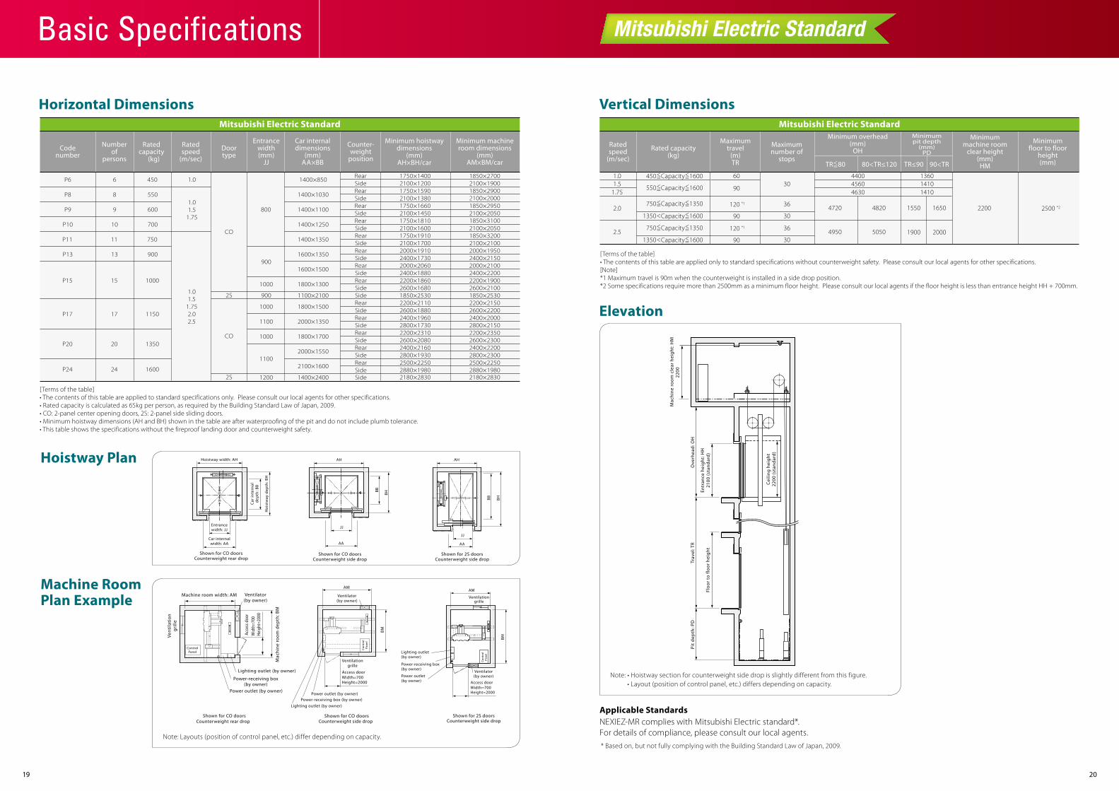
Horizontal Dimensions
Ratedcapacity
(kg)
Ratedspeed
(m/sec)
Numberof
persons
Codenumber
Doortype
Counter-weight
position
Car internaldimensions
(mm)AA×BB
Minimum hoistwaydimensions
(mm)AH×BH/car
Minimum machineroom dimensions
(mm)AM×BM/car
Entrancewidth(mm)
JJ
P6 6 450 1400×850
1400×1030P8 8 550
1400×1100P9 9 600
1400×1250P10 10 700
1400×1350P11 11 750
1600×1350P13 13 900
1600×1500
P15 15 1000
P17 17 1150
P20 20 1350
P24 24 1600
1800×1300
1100×2100
1800×1500
2000×1350
1800×1700
2000×1550
Rear
Rear
Rear
RearSide
Side1750×14002100×12001750×1590
1850×27001.0
2100×19001850×2900
Side 2100×1380 2100×20001750×1660 1850×29501.0
1.5 8001.75
2100×1450 2100×20501750×18102100×1600
CO
2S
CO
2S
SideRear
Rear
Rear
Rear
Rear
Rear
Rear
Rear
Side
Side
Side
SideSide
Side
Side
Side
SideRearSideSide
2100×20501850×3100
1750×1910 1850×32002100×1700 2100×21002000×1910 2000×19502400×1730
900
900
1000
1100
1000
1000
2100×16001100
1400×24001200
2400×21502000×2060 2000×21002400×1880 2400×22002200×1860 2200×19002600×16801850×2530
2600×21001850×2530
2200×2110 2200×2150
1.01.5
1.752.02.5
2600×1880 2600×22002400×1960 2400×20002800×1730 2800×21502200×2310 2200×23502600×2080 2600×23002400×2160 2400×22002800×1930 2800×23002500×2250 2500×22502880×1980 2880×19802180×2830 2180×2830
Mitsubishi Electric Standard
Mitsubishi Electric Standard
Vertical Dimensions
Elevation
[Terms of the table]• The contents of this table are applied only to standard specifications without counterweight safety. Please consult our local agents for other specifications.[Note]*1 Maximum travel is 90m when the counterweight is installed in a side drop position.*2 Some specifications require more than 2500mm as a minimum floor height. Please consult our local agents if the floor height is less than entrance height HH + 700mm.
1.0 601.5 30
90
36120 *1
3090
3090
36120 *1
1.75
2500 *2
4400 13604560 1410
2200
4630 1410
1550
1900
1650
2000
Ratedspeed
(m/sec)
Rated capacity(kg)
Maximumtravel
(m)TR
Maximumnumber of
stops
Minimum overhead(mm)
OH
Minimumpit depth
(mm)PD
Minimummachine room
clear height(mm)HM
Minimumfloor to floor
height(mm)
2.0
2.5
* Based on, but not fully complying with the Building Standard Law of Japan, 2009.
Note: • Hoistway section for counterweight side drop is slightly different from this figure. • Layout (position of control panel, etc.) differs depending on capacity.
Note: Layouts (position of control panel, etc.) differ depending on capacity.
Mac
hine
roo
m c
lear
hei
ght:
HM
2200
Ove
rhea
d: O
H
Entr
ance
hei
ght:
HH
2100
(sta
ndar
d)
Cei
ling
heig
ht22
00 (s
tand
ard
)
Trav
el: T
R
Floo
r to
floo
r he
ight
Pit
dep
th: P
D
Applicable StandardsNEXIEZ-MR complies with Mitsubishi Electric standard*.For details of compliance, please consult our local agents.
TR 80<= TR≤90 90<TR
4720
4950
4820
5050
550 Capacity 1600<= <=
450 Capacity 1600<= <=
750 Capacity 1350<= <=
<1350 Capacity 1600<=
750 Capacity 1350<= <=
1350 Capacity 1600< <=
Mitsubishi Electric Standard
Basic Specifications
80<TR≤120
Hoistway Plan Hoistway width: AH
Entrancewidth: JJ
JJ
Car internalwidth: AA AA
Car
inte
rnal
dep
th: B
B
Hoi
stw
ay d
epth
: BH
Shown for CO doorsCounterweight rear drop
AH
JJ
AA
Shown for CO doorsCounterweight side drop
Shown for 2S doorsCounterweight side drop
BB
BH
Machine RoomPlan Example
[Terms of the table]• The contents of this table are applied to standard specifications only. Please consult our local agents for other specifications.• Rated capacity is calculated as 65kg per person, as required by the Building Standard Law of Japan, 2009.• CO: 2-panel center opening doors, 2S: 2-panel side sliding doors.• Minimum hoistway dimensions (AH and BH) shown in the table are after waterproofing of the pit and do not include plumb tolerance.• This table shows the specifications without the fireproof landing door and counterweight safety.
AH
BHBB
Shown for 2S doorsCounterweight side drop
Ventilationgrille
Ventilator(by owner)
Access doorWidth=700Height=2000
Con
trol
Pane
l
AM
BM
Lighting outlet (by owner)
Power outlet (by owner)
Power-receiving box (by owner)
Shown for CO doorsCounterweight side drop
Access door
Ventilationgrille
Width=700Height=2000
AM
BM
Lighting outlet (by owner)
Power outlet (by owner)
Ventilator(by owner)
Power-receiving box (by owner)
Con
trol
Pane
l
Ventilator(by owner)
Machine room width: AM
Vent
ilati
ongr
ille
Mac
hine
roo
m d
epth
: BM
Acce
ss d
oor
Wid
th=7
00He
ight
=200
0
ControlPanel
Power-receiving box(by owner)
Lighting outlet (by owner)
Power outlet (by owner)
Shown for CO doorsCounterweight rear drop
2221
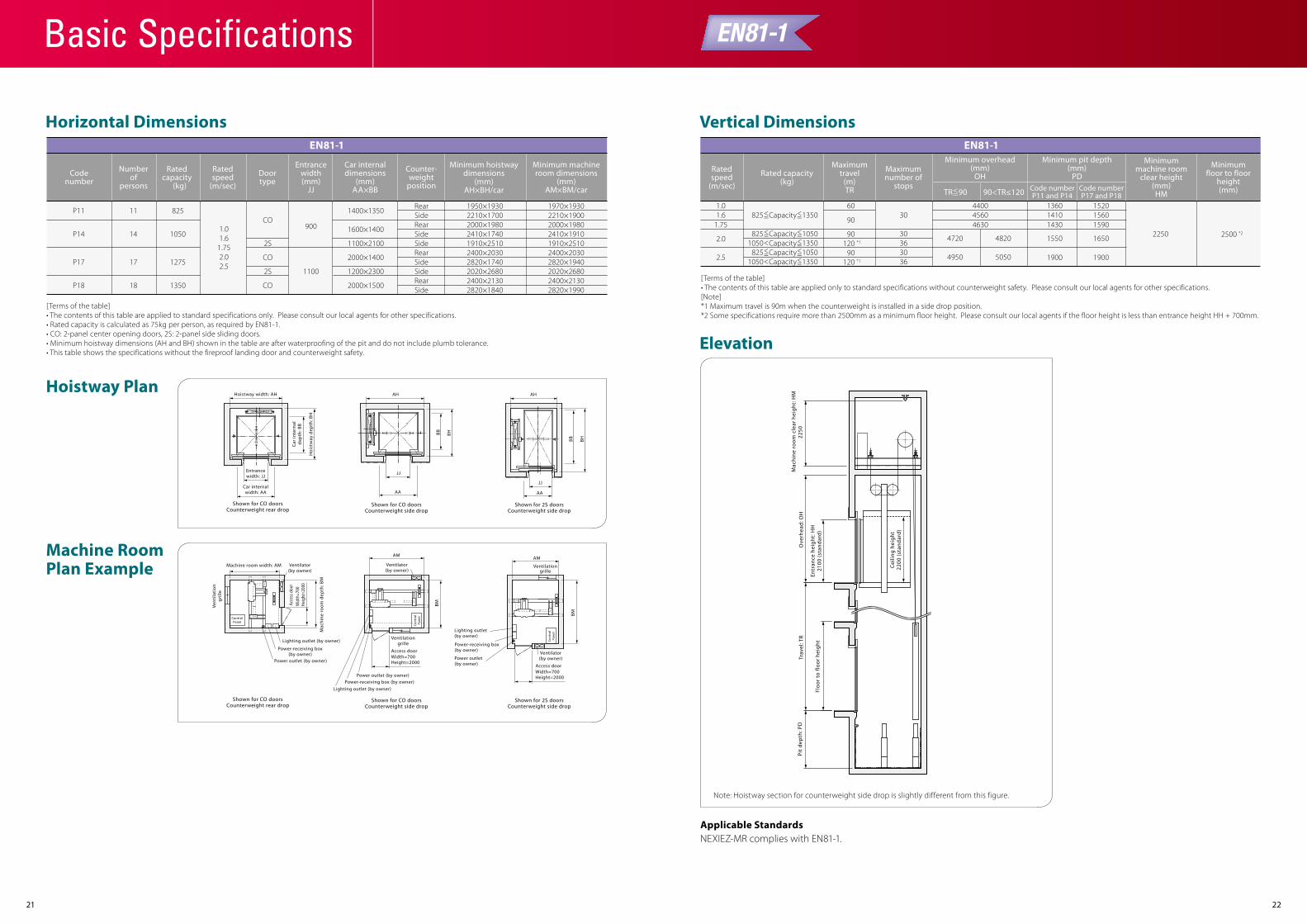
Horizontal Dimensions
EN81-1
Ratedcapacity
(kg)
Ratedspeed
(m/sec)
Numberof
persons
Codenumber
Doortype
Counter-weight
position
Car internaldimensions
(mm)AA×BB
Minimum hoistwaydimensions
(mm)AH×BH/car
Minimum machineroom dimensions
(mm)AM×BM/car
Entrancewidth(mm)
JJ
1400×1350P11 11 825
P14 14 1050
P17 17 1275
P18 18 1350
1600×1400
1100×2100
2000×1400
1200×2300
2000×1500
Rear
Rear
Side
Side
Rear
Side
Side
Rear
Side
Side
1950×1930 1970×19302210×1700 2210×19002000×1980 2000×19802410×1740
900
11002S
CO
2S
CO
CO
2410×19101910×25102400×20302820×19402020×26802400×21302820×1990
1910×25102400×20302820×17402020×26802400×2130
1.01.6
1.752.02.5
2820×1840
[Terms of the table]• The contents of this table are applied to standard specifications only. Please consult our local agents for other specifications.• Rated capacity is calculated as 75kg per person, as required by EN81-1.• CO: 2-panel center opening doors, 2S: 2-panel side sliding doors.• Minimum hoistway dimensions (AH and BH) shown in the table are after waterproofing of the pit and do not include plumb tolerance.• This table shows the specifications without the fireproof landing door and counterweight safety.
EN81-1
Hoistway PlanHoistway width: AH
Entrancewidth: JJ
JJ
Car internalwidth: AA AA
Car
inte
rnal
dep
th: B
B
Hoi
stw
ay d
epth
: BH
Shown for CO doorsCounterweight rear drop
AH
Shown for CO doorsCounterweight side drop
Shown for CO doorsCounterweight rear drop
Shown for CO doorsCounterweight side drop
Shown for 2S doorsCounterweight side drop
Shown for 2S doorsCounterweight side drop
BB BH
Machine RoomPlan Example
JJ
AA
AH
BHBB
Con
trol
Pane
l
Access door
Ventilationgrille
Ventilationgrille
Ventilator(by owner)Width=700
Height=2000Access doorWidth=700Height=2000
Con
trol
Pane
lAM
BM
Lighting outlet (by owner)
Power outlet (by owner)
AM
BMVentilator(by owner)
Machine room width: AM
Vent
ilati
ongr
ille
Mac
hine
roo
m d
epth
: BM
Acce
ss d
oor
Wid
th=7
00He
ight
=200
0
ControlPanel
Power-receiving box(by owner)
Lighting outlet (by owner)
Power outlet (by owner)
Ventilator(by owner)
Power-receiving box (by owner)
Lighting outlet (by owner)
Power outlet (by owner)
Power-receiving box (by owner)
Vertical Dimensions
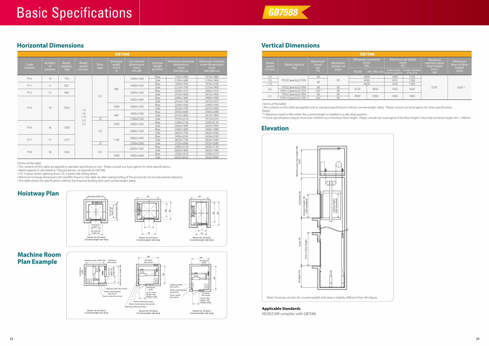
Elevation
[Terms of the table]• The contents of this table are applied only to standard specifications without counterweight safety. Please consult our local agents for other specifications.[Note]*1 Maximum travel is 90m when the counterweight is installed in a side drop position.*2 Some specifications require more than 2500mm as a minimum floor height. Please consult our local agents if the floor height is less than entrance height HH + 700mm.
1.0 601.6 30
30
90
9036120 *1
309036120 *1
1.752500 *2
4400 13604560 1410
22504630 1430
1550
1900
152015601590
1650
1900
Ratedspeed
(m/sec)
Rated capacity(kg)
Maximumtravel
(m)TR
Maximumnumber of
stops
Minimum overhead(mm)
OH
Minimum pit depth(mm)
PDCode numberP11 and P14
Code numberP17 and P18
Minimummachine room
clear height(mm)HM
Minimumfloor to floor
height(mm)
2.0
2.5
Applicable StandardsNEXIEZ-MR complies with EN81-1.
TR 90<=
4720
4950
4820
5050
90<TR≤120
825 Capacity 1350<= <=
825 Capacity 1050<= <=1050 Capacity 1350< <=
825 Capacity 1050<= <=1050 Capacity 1350< <=
EN81-1
Note: Hoistway section for counterweight side drop is slightly different from this figure.
Cei
ling
heig
ht22
00 (s
tand
ard
)
Ove
rhea
d: O
HTr
avel
: TR
Pit
dep
th: P
D
Floo
r to
floo
r he
ight
Mac
hine
roo
m c
lear
hei
ght:
HM
2250
Entr
ance
hei
ght:
HH
2100
(sta
ndar
d)
Basic Specifications
2423
Horizontal Dimensions
Ratedcapacity
(kg)
Ratedspeed
(m/sec)
Numberof
persons
Codenumber
Doortype
Counter-weight
position
Car internaldimensions
(mm)AA×BB
Minimum hoistwaydimensions
(mm)AH×BH/car
Minimum machineroom dimensions
(mm)AM×BM/car
Entrancewidth(mm)
JJ
1400×1300P10 10 750
1400×1350
1600×1330
1600×1400
RearSide
1950×1880 1970×18802190×16801950×19302210×17002000×19102410×16902000×19802410×17402200×19302610×17002000×20802410×18401910×25102200×21302620×18402400×19802820×17002400×20302820×17402020×26802400×21302820×18402200×23102620×2020
RearSideRearSideRearSideRearSideRearSide
RearSideRearSideRearSide
RearSideRearSide
Side
Side
2190×19001970×19302210×19002000×19102410×19002000×19802410×19102200×19302610×19002000×20802410×19601910×25102200×21302620×19902400×19802820×19302400×20302820×19402020×26802400×21302820×19902200×23102620×2080
P11 11 825
P12 12 900
P14 14 1050
P16 16 1200
P17 17 1275
P18 18 1350
900
1000
900
1000
1100
1000
2S
CO
CO
2S
CO
1800×1350
1600×1500
1100×2100
1800×1500
2000×1350
2000×1400
1200×2300
2000×1500
1800×1680
1.01.6
1.752.02.5
[Terms of the table]• The contents of this table are applied to standard specifications only. Please consult our local agents for other specifications.• Rated capacity is calculated as 75kg per person, as required by GB7588.• CO: 2-panel center opening doors, 2S: 2-panel side sliding doors.• Minimum hoistway dimensions (AH and BH) shown in the table are after waterproofing of the pit and do not include plumb tolerance.• This table shows the specifications without the fireproof landing door and counterweight safety.
GB7588
Hoistway PlanHoistway width: AH
Entrancewidth: JJ
JJ
Car internalwidth: AA AA
Car
inte
rnal
dep
th: B
B
Hoi
stw
ay d
epth
: BH
Shown for CO doorsCounterweight rear drop
AH
Shown for CO doorsCounterweight side drop
BB BH
Machine RoomPlan Example
Shown for CO doorsCounterweight rear drop
Shown for CO doorsCounterweight side drop
Shown for 2S doorsCounterweight side drop
Shown for 2S doorsCounterweight side drop
JJ
AA
AH
BHBB
Con
trol
Pane
l
Access door
Ventilationgrille
Ventilationgrille
Ventilator(by owner)Width=700
Height=2000Access doorWidth=700Height=2000
Con
trol
Pane
l
AM
BM
Lighting outlet (by owner)
Power outlet (by owner)
AM
BM
Ventilator(by owner)
Machine room width: AM
Vent
ilati
ongr
ille
Mac
hine
roo
m d
epth
: BM
Acce
ss d
oor
Wid
th=7
00He
ight
=200
0
ControlPanel
Power-receiving box(by owner)
Lighting outlet (by owner)
Power outlet (by owner)
Ventilator(by owner)
Power-receiving box (by owner)
Lighting outlet (by owner)
Power outlet (by owner)
Power-receiving box (by owner)
GB7588
Vertical Dimensions
Elevation
[Terms of the table]• The contents of this table are applied only to standard specifications without counterweight safety. Please consult our local agents for other specifications.[Note]*1 Maximum travel is 90m when the counterweight is installed in a side drop position.*2 Some specifications require more than 2500mm as a minimum floor height. Please consult our local agents if the floor height is less than entrance height HH + 700mm.
1.0 601.6 30
30
90
9036120 *1
309036120 *1
1.752500 *2
4400 13604560 1410
22504630 1430
1550
1900
152015601590
1650
1900
Ratedspeed
(m/sec)
Rated capacity(kg)
Maximumtravel
(m)TR
Maximumnumber of
stops
Minimum overhead(mm)
OH
Minimum pit depth(mm)
PDCode number
P10-P12 and P14Code number
P16-P18
Minimummachine room
clear height(mm)HM
Minimumfloor to floor
height(mm)
2.0
2.5
Applicable StandardsNEXIEZ-MR complies with GB7588.
TR 90<=
4720
4950
4820
5050
90<TR≤120
750 Capacity 1350<= <=
750 Capacity 1050<= <=1050 Capacity 1350< <=
750 Capacity 1050<= <=1050 Capacity 1350< <=
GB7588
Note: Hoistway section for counterweight side drop is slightly different from this figure.
Cei
ling
heig
ht22
00 (s
tand
ard
)
Ove
rhea
d: O
HTr
avel
: TR
Pit
dep
th: P
D
Floo
r to
floo
r he
ight
Mac
hine
roo
m c
lear
hei
ght:
HM
2250
Entr
ance
hei
ght:
HH
2100
(sta
ndar
d)
Basic Specifications
2625
Work Not Included in Elevator Contract
Elevator Site Requirements
Ordering Information
The following items are excluded from Mitsubishi Electric’s elevator installation work, and are therefore the responsibility of the building owner or general contractor:
• Construction of the elevator machine room with proper beams and slabs, equipped with a lock, complete with illumination, ventilation and waterproofing.
• Access to the elevator machine room sufficient to allow passage of the control panel and traction machine.
• Architectural finishing of the machine room floor, and the walls and floors in the vicinity of the entrance hall after installation has been completed.
• Construction of an illuminated, ventilated and waterproofed elevator hoistway.
• A ladder to the elevator pit.
• The provision of cutting the necessary openings and joists.
• Separate beams, when the hoistway dimensions markedly exceed the specifications, and intermediate beams when two or more elevators are installed.
• All other work related to building construction.
• The machine room power-receiving panel and the electrical wiring for illumination, plus the electrical wiring from the electrical room to the power-receiving panel.
• The laying of conduits and wiring between the elevator pit and the terminating point for the devices installed outside the hoistway, such as the emergency bell, intercom, monitoring and security devices, etc.
• The power consumed in installation work and test operations.
• All the necessary building materials for grouting in of brackets, bolts, etc.
• The test provision and subsequent alteration as required, and eventual removal of the scaffolding as required by the elevator contractor, and any other protection of the work as may be required during the process.
• The provision of a suitable, locked space for the storage of elevator equipment and tools during elevator installation.
• The security system, such as a card reader, connected to Mitsubishi Electric’s elevator controller, when supplied by the building owner or general contractor.
* Work responsibilities in installation and construction shall be determined according to local laws. Please consult our local agents for details.
• The temperature of the machine room and elevator hoistway shall be below 40˚C.
• The following conditions are required for maintaining elevator performance.
a. The relative humidity shall be below 90% on a monthly average and below 95% on a daily average.
b. Prevention shall be provided against icing and condensation occurring due to a rapid drop in the temperature in the machine room and elevator hoistway.
c. The machine room and the elevator hoistway shall be finished with mortar or other materials so as to prevent concrete dust.
• Voltage fluctuation shall be within a range of +5% to -10%.
Please include the following information when ordering or requesting estimates:
• The desired number of units, speed and loading capacity.
• The number of stops or number of floors to be served.
• The total elevator travel and each floor-to-floor height.
• Operation system.
• Selected design and size of car.
• Entrance design.
• Signal equipment.
• A sketch of the part of the building where the elevators are to be installed.
• The voltage, number of phases, and frequency of the power source for the motor and lighting.
Mitsubishi Elevator Asia Co., Ltd. has acquired ISO 9001 certification by the International Standards Organization (ISO) based on a review of quality management.The company has also acquired environmental management system standard ISO 14001 certification.
Important Information on Elevator Planning

C-CL1-3-C9113-B INA-1310 Printed in Japan (MDOC)
Eco Changes is the Mitsubishi Electric Group’s environmental statement,and expresses the Group’s stance on environmental management. Through a wide range of businesses, we are helping contribute to the realization of a sustainable society.
Visit our website at:http://www.mitsubishielectric.com/elevator/
PASSENGER ELEVATORS
Revised publication effective Oct. 2013.Superseding publication of C-CL1-3-C9113-A Mar. 2013.
Specifications are subject to change without notice.
2013