
Excellent Clamping Hydraulic Clamping Devices - Guima-mh.com
www.pascaleng.co.jp
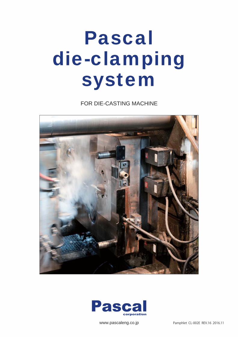
Pascaldie-clamping
system
Pamphlet CL-002E REV.16 2016.11
FOR DIE-CASTING MACHINE
- 1 -
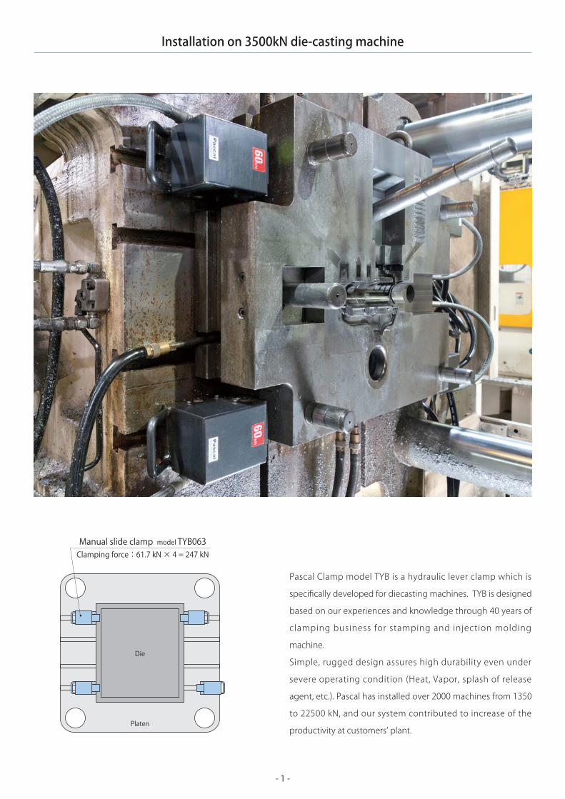
Installation on 3500kN die-casting machine
Pascal Clamp model TYB is a hydraulic lever clamp which is
specifically developed for diecasting machines. TYB is designed
based on our experiences and knowledge through 40 years of
clamping business for stamping and injection molding
machine.
Simple, rugged design assures high durability even under
severe operating condition (Heat, Vapor, splash of release
agent, etc.). Pascal has installed over 2000 machines from 1350
to 22500 kN, and our system contributed to increase of the
productivity at customers’ plant.
Clamping force:61.7 kN × 4 = 247 kNManual slide clamp model TYB063
Platen
Die

- 2 -
Pascal auto slide type of TYB is also available. It is provided
being equipped with a pneumatic cylinder to have clamp slid
in the T-slot.
By depressing the button on the operation panel, the clamps
automatically slide and clamp or unclamp in a matter of
seconds, therefore, clamping operation is much easier than
the one without a pneumatic cylinder.
In addition, die detection sensor and backward end detection
sensor provided with clamp enable the system to build up
safety interlocking with the machine control, which allows
the die change operation safer and more sophisticated.
Installation on 6500kN die-casting machine
Air cylinder
Die detection sensor
Backward enddetection sensor
Clamping force:98 kN × 4 = 392 kNAuto-slide clamp
Platen
Die

- 3 -
Advantage of Pascal die clamping system
Advantage 1
Operator can just press a button and fix the die to the
machine without dangerous and hard work.
● Tightening heavy bolts in narrow and slippery spaces
● Hazardous working condition (Vapor, High temperature, etc.)
● Low back pain
Advantage 2
Clamp
Die
As a typical example, introduction of Pascal die clamping system could reduce the die change time from 60 minutes to
30 minutes.
It is a must for the die casters that their plant operation be
capable o f compromis ing the needs of decreas ing
production lot and increasing variation of products, and at
the same time shortening of delivery and lowering the
production cost.
Pascal offers its reliable, durable, unique and cost efficient
die clamping system in accordance with individual system
requirements and customer specific conditions.
Introduction of Pascal die clamping system
Small lot, short delivery Easy die change
Efficient operation and Comfortable working circumstances
Stockless Reduction of die changing time
Operator’s safety
Just-in-Time production Man-hour saving
Conventional die change Introduction of Pascal die clamping system
Conventional die change
Pascal die clamping system
Operator Die change timeMachine working time
Saved time
90 min.
12 hours
model TYB250
- 4 -
A A
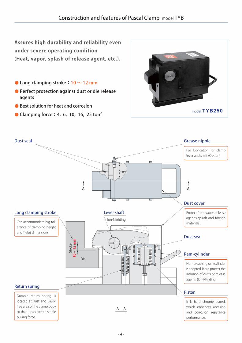
Construction and features of Pascal Clamp model TYB
Long clamping stroke:10 ~ 12 mm
Perfect protection against dust or die release agents
Best solution for heat and corrosion
Clamping force:4, 6, 10, 16, 25 tonf
A - A
Return springPiston
Ram-cylinder
It is hard chrome plated, which enhances abrasion and corrosion resistance performance.
Dust seal
Dust seal
Dust cover
Protect from vapor, release agent’s splash and foreign materials
Long clamping stroke Lever shaftIon-Nitriding
Grease nipple
For lubrication for clamp lever and shaft (Option)
Non-breathing ram cylinder is adopted. It can protect the intrusion of dusts or release agents. (Ion-Nitriding)
Can accommodate big tol- erance of clamping height and T-slot dimensions
Durable return spring is located at dust and vapor free area of the clamp body so that it can exert a stable pulling force.
Die
Stroke
10 ~ 12 mm
Assures high durability and reliability evenunder severe operating condition(Heat, vapor, splash of release agent, etc.).
51
P
Q
N
F
YZX
h
K
ML
V
DJ
ET
GC
SR
B
A
(mm)
- 5 -
~ 2000 kN~ 3500 kN~ 5500 kN~ 8500 kN~13000 kN~20000 kN~26000 kN
156 kN246 kN392 kN624 kN980 kN1470 kN1960 kN
HCSD-HG2SSSHCLD-HG2SSS
HCLD-HG22SSS
888881216
TYB040 ×TYB063 ×TYB100 ×TYB160 ×TYB250 ×TYB250 ×TYB250 ×
G MIN. h ~ MAX. h※4
MIN. J※3VTSRMAX. Q
※2PNMK L MIN. E
27.5 (43≦h)32.5 (38≦h<43)37.5 (33≦h<38)
TYB040
TYB063
TYB100
TYB160
TYB250
13
13
14
15
20
145
168
200
235
285
23
30
30
30
35
122
138
170
205
250
16
20
20
20
20
32.5
38
62
80
95
32
36
45
55
65
83
103
113
133
168
39.6
49.6
54.6
59.6
72
64.5
71.5
94.5
110
156
-
58
76
96
118
74.5
81.5
105
122
168
33 ~ 50
28 ~ 60
36 ~ 70
38 ~ 80
38 ~ 88
(TYB160 × 12)(TYB160 × 16)
(936 kN)(1248 kN)
29.5 (48≦h)39.5 (38≦h<48)49.5 (28≦h<38)45 (56≦h)55 (46≦h<56)65 (36≦h<46)60 (58≦h)70 (48≦h<58)80 (38≦h<48)106 (58≦h)116 (48≦h<58)126 (38≦h<48)
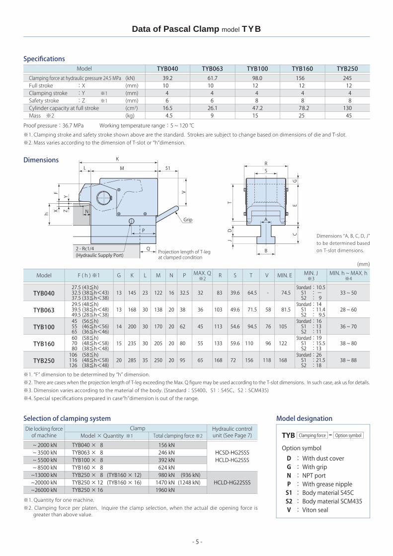
39.210 4 616.5 4.5
TYB06361.710 4 626.1 9
(kN)(mm)(mm)(mm)(cm3)(kg)
TYB10098.012 4 847.215
156 12 4 8 78.2 25
245 12 4 8130 45
TYB160 TYB250TYB040Model
Specifications
Dimensions
Clamping force at hydraulic pressure 24.5 MPaFull stroke :XClamping stroke :Y ※1Safety stroke :Z ※1Cylinder capacity at full strokeMass ※2
Proof pressure:36.7 MPa Working temperature range:5 ~ 120 ℃
※1. Clamping stroke and safety stroke shown above are the standard. Strokes are subject to change based on dimensions of die and T-slot.※2. Mass varies according to the dimension of T-slot or “h”dimension.
2 - Rc1/4(Hydraulic Supply Port)
Grip
Projection length of T-legat clamped condition
Dimensions “A, B, C, D, J”to be determined basedon T-slot dimensions.
Model F ( h ) ※1
Standard:10.5 S1 : - S2 : 9Standard:14 S1 :11.4 S2 : 9.5
Standard:19 S1 :15.5 S2 :13Standard:26 S1 :21.5 S2 :18
Standard:16 S1 :13 S2 :11
※1. “F” dimension to be determined by “h” dimension.※2. There are cases when the projection length of T-leg exceeding the Max. Q figure may be used according to the T-slot dimensions. In such case, ask us for details.※3. Dimension varies according to the material of the body. (Standard:SS400、S1:S45C、S2:SCM435)※4. Special specifications prepared in case“h”dimension is out of the range.
Selection of clamping system Model designationHydraulic controlunit (See Page 7)
Die locking forceof machine
ClampModel × Quantity ※1 Total clamping force ※2
※1. Quantity for one machine.※2. Clamping force per platen. Inquire the clamp selection, when the actual die opening force is
greater than above value.
Data of Pascal Clamp model TYB
TYB Clamping force Option symbol
Option symbol
: With dust cover: With grip: NPT port: With grease nipple: Body material S45C: Body material SCM435: Viton seal
DGNPS1S2V

H
L AA
h
- 6 -
a
b
h
cd
j
(mm)
a b d j a d j
2228283236
+0.5 0+0.5 0+0.5 0+0.5 0+0.5 0
3746465356
+3 0+4 0+4 0+4 0+4 0
1620202430
1519232732
1416182129
11.515172027
+2 0+2 0+2 0+2 0+2 0
2228282832
± 0.2
± 0.2
± 0.2
± 0.2
± 0.2
(mm)
20≦h<25 25≦h<30 30≦h<35 35≦h<40 40≦h<45 45≦h<50 50≦hMIN. L AA
20----
252535--
253035--
253035--
-304040-
---40-
---4550
(30)(30) (30) (35)
1520202530(20)
1012.512.51010(12.5)
TYB040TYB063TYB100TYB160TYB250
TYB040TYB063TYB100TYB160TYB250
MIN. H
Specify T-slot dimensions “a, b, d, j” and clamping height (sub-plate thickness) “h”.
Regarding “d” dimension
Retrofit :Specify to 0.1 mm.
New machine :Machining tolerance shall be ±0.2 mm or better.
Recommended T-slot dimensions are shown in the following table.
Minimum T-slot dimensions are also shown. Contact Pascal if your T-slot dimensions
are less than these figures.
T-slot dimensions and clamping height
●
●
●
●
Clamp area details (Groove)
Model
Model
Recommended T-slot dimensions Minimum T-slot dimensions
To accommodate the clamp to the die as shown on the
right, Pascal can provide special designed clamp lever
with the clamp.
Specify the dimension H, L and h of the die when ordering.
The figures shown in the column L and H in the table are a
minimum dimension to make.
Data of Pascal Clamp model TYB
Die
● Auto slide type
Option (The following models are available as the options. Contact Pascal for more information.)
Model TYB with air cylinder for sl iding function. The clamp can go forward or backward by a switch on operation panel so that die change operation time can be shortened further.
● With die detection limit switch
PA
PHRA A
XPA
PHR
S
- 7 -
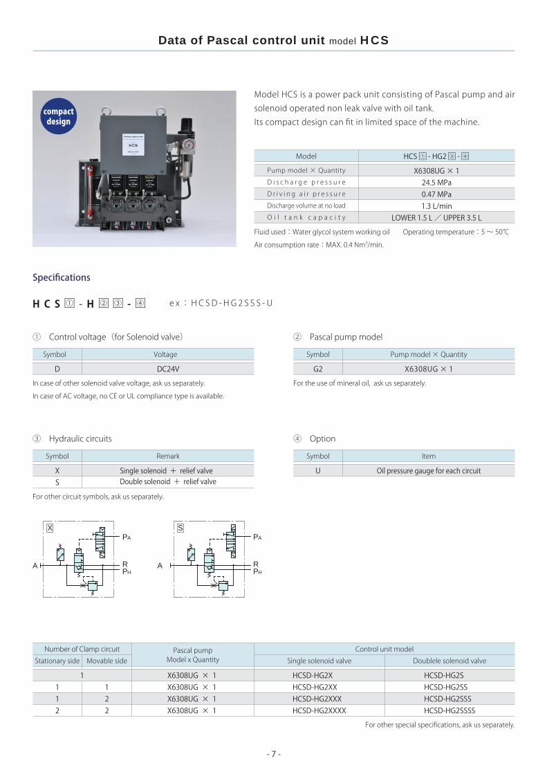
HCS - HG2 - ① ④③□ □ □
24.5 MPa0.47 MPa1.3 L/min
LOWER 1.5 L / UPPER 3.5 L
112
1122
HCSD-HG2XHCSD-HG2XXHCSD-HG2XXXHCSD-HG2XXXX
HCSD-HG2SHCSD-HG2SSHCSD-HG2SSSHCSD-HG2SSSS
H C S - H - □ □□ □① ④② ③
D DC24V G2
UXS
For the use of mineral oil, ask us separately.In case of other solenoid valve voltage, ask us separately.
In case of AC voltage, no CE or UL compliance type is available.
Model HCS is a power pack unit consisting of Pascal pump and air
solenoid operated non leak valve with oil tank.
Its compact design can fit in limited space of the machine.
X6308UG × 1Pump model × Quantity
D i s c h a r g e p r e s s u r e
D r i v i n g a i r p r e s s u r e
Discharge volume at no load
O i l t a n k c a p a c i t y
Specifications
① Control voltage(for Solenoid valve) ② Pascal pump model
Model
④ Option③ Hydraulic circuits
For other circuit symbols, ask us separately.
Fluid used:Water glycol system working oil Operating temperature:5 ~ 50℃
Air consumption rate:MAX. 0.4 Nm3/min.
Symbol Pump model × QuantitySymbol Voltage
SymbolSymbol Remark
Single solenoid + relief valveDouble solenoid + relief valve
Oil pressure gauge for each circuit
Control unit modelNumber of Clamp circuit
Stationary side Movable side Single solenoid valve Doublele solenoid valvePascal pumpModel x Quantity
X6308UG × 1X6308UG × 1X6308UG × 1X6308UG × 1
For other special specifications, ask us separately.
e x:HC S D - H G 2 S S S - U
Item
compactdesign
Data of Pascal control unit model HCS
X6308UG × 1

A2
A1 PA
S
S
S
A3
378.3
89 192 94
345
150
27.5
15B (49) (49) 116
15
23.5A
83
205
315
1532015
23.5
60109.5
202.6
200
545
214
134.7
109.5
260
6.8
10 10320
370350
27 30 27.5
150
M10
310
350
680
↑A
100 30
160
3012
20
100
- 8 -
HCS□-HG2SSS①
234185136137
350350350400
1234
18212427
B (mm)A (mm)
modelZPS-B5
modelZPS-S0
Dimensions
Circuit diagrams
Diagrams shown in this page are for 1 to 3 hydraulic circuits.For 4 circuits application, ask us for details.
Oil inlet Pascal Pump
Air solenoid valve for clamp control
Pressure switch
Terminal board
Eyebolt (M8)
Filter regulator
Oil gauge
4-ø11 M10Mounting bolt hole
Air bleeding valve
Pascal Relief valve Pascal non leak valve
Drain port Rc1/4
Air supply port "PA"Rc1/4
Return portwith check valve
Pump dismantleinterference area
Conduit connection port position
154.7
View A
Data of Pascal control unit model HCS
Conduitconnection port ø28
Hydraulic port "A" Rc1/4
Number of Hydraulic circuit
Accessories for model HCS Unit (Option)
Antivibration rubber Stand
Mass (kg)
Anti vibrationrubber:ZPS-B5
Model HCL should be chosen in case of the following cases.1. Double pump type is required.2. The signal of Abnormal high pressure is required for interlocking.3. More than five circuits of hydraulic valve are required.

- 9 -
1 .3L/min 2.6L/min
□□ □HCL - HG22 - ① ④③□ □HCL - HG2 - ① ④③ □
24.5 MPa0.47 MPa
LOWER 2.2 L / UPPER 5.4 L
H C L - H - □ □ □ □
D DC24V G2G22
XS
L
T2
T3
A
A
B
A
A
BB
1212
2222
HCLD-HG2XXXHCLD-HG2XXXXHCLD-HG22XXXHCLD-HG22XXXX
HCLD-HG2SSSHCLD-HG2SSSSHCLD-HG22SSSHCLD-HG22SSSS
DC24V only available.
Model HCL is a power pack unit consisting of Pascal pump, non
leak valve and large oil tank, which is ideal power source for mid
and large size of machine. Double pump type is also available on
this model to shorten the cylinder actuation time.
X6308UG × 1 X6308UG × 2
e x:HC L D - H G 2 2 S S S - L
For the use of mineral oil, ask us separately.
X6308UG × 1X6308UG × 1X6308UG × 2X6308UG × 2
Data of Pascal control unit model HCL
compactdesign
Specifications
Pump model × Quantity
D i s c h a r g e p r e s s u r e
D r i v i n g a i r p r e s s u r e
Discharge volume at no load
O i l t a n k c a p a c i t y
Model
Fluid used:Water glycol system working oil Operating temperature:5 ~ 50℃
Air consumption rate:MAX. 0.4 Nm3/min. (Single pump) MAX. 0.8 Nm3/min. (Double pump)
X6308UG × 1X6308UG × 2
① Control voltage(for Solenoid valve) ② Pascal pump model
Symbol Pump model × QuantitySymbol Voltage
④ Option③ Hydraulic circuits
SymbolSymbol Remark Item
Single solenoid + relief valveDouble solenoid + relief valve
Low oil level detection switch
For other circuit symbols, ask us separately.
Control unit modelNumber of Clamp circuit
Stationary side Movable side Single solenoid valve Doublele solenoid valvePascal pumpModel x Quantity
For other special specifications, ask us separately.
2 position double solenoid air valve × 2(for vertical clamp slider and mold positioning pin)
3 position exhaust center double solenoid air valve × 2(for horizontal clamp slider)

290
45
49 49 49 L
84
83
430
412
429.9
160
27.5
215
15460
15
3365
1540015
119.5
242
200
555
167.5
283.5
224.5
10.5
237.1
119.5
1515 ※460
※430
160
27.530 35
ø60
M12
※410
※410
140 30
※460
※460
200
200
2525
204.5
140
34.5
15
- 10 -
204179.5155155
1234
26293234
L (mm)
100
260
45.595
25 25
30200 15
260
modelZPS-B6
modelZPS-S4
modelZPS-PZXA7320
Diagrams shown in this page are 1 to 4 hydraulic circuits. For 5 or more circuits application, ask us for details.
Digital pressure gauge outputs the signal of pressure build-up and excessive high pressure.
Rc1/4 is for 1 pump type.Rc3/8 for 2 pumps.
※2.
※3.
Mass (kg) ※1
Anti vibrationrubber:ZPS-B6
Data of Pascal control unit model HCL
DimensionsNumber of Hydraulic circuit
※1. 1 unit of pump is included. 3 kg to be added when 2 pumps applied.M12 Mounting bolt hole
Pascal pump
4-ø14
Conduit connection
port position 200.5
Oil inletAir pressuregauge
Stop valve
Air solenoid valvefor clamp control
Terminalboard
Eyebolt(M8)
Digital pressuregauge ※2
Conduit connection port ø28
Conduit connection port ø22
M12 Mountingbolt hole
Filter regulator
Oil gauge
Drain portRc1/4
4-ø14
Air supply port "PA"Rc3/8 ※3
Return portwith check valve
Pump dismantle interference area
Accessories for model HCL Unit (Option)
Antivibration rubber
Stand Stand
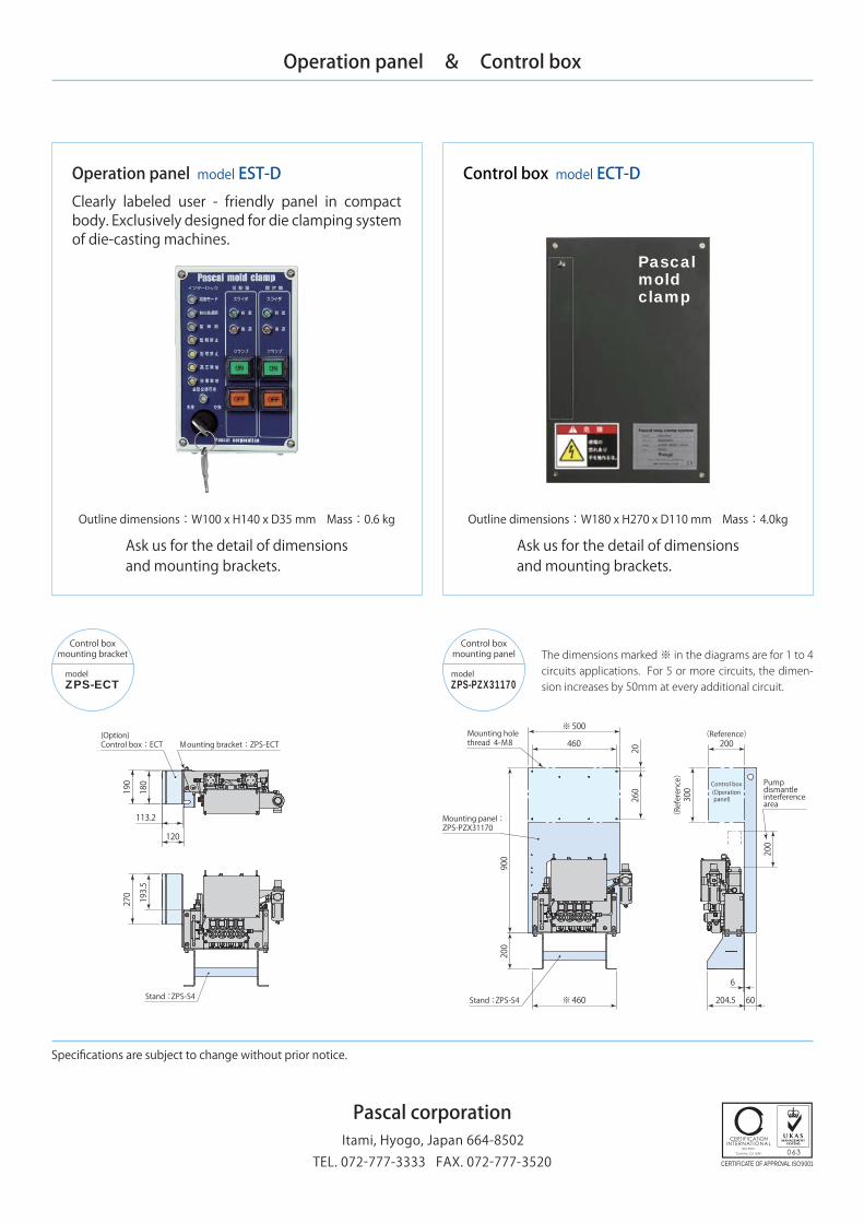
The dimensions marked ※ in the diagrams are for 1 to 4 circuits applications. For 5 or more circuits, the dimension increases by 50mm at every additional circuit.
Stand:ZPS-PZXA7320
Stand:ZPS-S4
Pascalmoldclamp
270 193.5
190
180
113.2
120
modelZPS-ECT
200
900
※500
460
※460
20260
200
200
300
60
6
204.5
modelZPS-PZX31170
Operation panel & Control box
Control box model ECT-DOperation panel model EST-D
Outline dimensions:W100 x H140 x D35 mm Mass:0.6 kg
Ask us for the detail of dimensionsand mounting brackets.
Ask us for the detail of dimensionsand mounting brackets.
Outline dimensions:W180 x H270 x D110 mm Mass:4.0kg
Specifications are subject to change without prior notice.
Clearly labeled user - friendly panel in compact body. Exclusively designed for die clamping system of die-casting machines.
Itami, Hyogo, Japan 664-8502TEL. 072-777-3333 FAX. 072-777-3520 CERTIFICATE OF APPROVAL ISO9001
Pascal corporation
Stand:ZPS-S4
Mounting bracket:ZPS-ECT
Stand:ZPS-S4
(Reference)
(Reference)
Control boxmounting bracket
Control boxmounting panel
(Option)Control box:ECT
Mounting holethread 4-M8
Mounting panel:ZPS-PZX31170
Pumpdismantleinterferencearea
Control box(Operation panel)
The dimensions marked ※ in the diagrams are for 1 to 4 circuits applications. For 5 or more circuits, the dimen-sion increases by 50mm at every additional circuit.