PAS Static Test Plan - Alpha Magnetic Spectrometer · JSC 29964 LMSEAT 34105 Test Plan for the...
61
JSC 29964 LMSEAT 34105 Alpha Magnetic Spectrometer 02 (AMS-02) Test Plan for the Static Test of the Passive Payload Attach System (PAS) Prepared by Lockheed Martin Space Operations Houston, Texas For Space and Life Sciences Directorate Flight Projects Division National Aeronautics and Space Administration Lyndon B. Johnson Space Center Houston, Texas January 2003 Revision: Baseline
Transcript of PAS Static Test Plan - Alpha Magnetic Spectrometer · JSC 29964 LMSEAT 34105 Test Plan for the...
JSC 29964
LMSEAT 34105
Alpha Magnetic Spectrometer 02 (AMS-02) Test Plan for the Static Test of the Passive Payload Attach System (PAS)
Prepared by
Lockheed Martin Space Operations Houston, Texas For
Space and Life Sciences Directorate Flight Projects Division National Aeronautics and Space Administration Lyndon B. Johnson Space Center Houston, Texas January 2003 Revision: Baseline

JSC 29964 LMSEAT 34105
Test Plan for the AMS-02 PAS Static Test
Prepared by:
Original signed by Hsing Ju on 27 Jan 2003 Hsing Ju, Test Engineer Lockheed Martin Space Operations
Reviewed by:
Original signed by C. Balasubramanian on 29 Jan 2003 Chittur Balasubramanian, Stress Analysis Lead Lockheed Martin Space Operations
Original signed by Phil Mott on 27 Jan 2003 Phil Mott, Certification & Test Lead Lockheed Martin Space Operations
Original signed by Kornel Nagy on 28 Jan 2003 Kornel Nagy, PhD, ES2 – ISS System Manager (Structures)
NASA/JSC
Original signed by Trent Martin on 27 Jan 2003
Trent Martin, Structural Analysis Lead Lockheed Martin Space Operations
ii

JSC 29964 LMSEAT 34105
Test Plan for the AMS-02 PAS Static Test
Approved by:
Original signed by Mike Trznadel on 29 Jan 2003 Mike Trznadel, Manager - Structural Analysis Section Lockheed Martin Space Operations
Original signed by Kenneth Bollweg on 30 Jan 2003 Kenneth Bollweg, AMS-02 Project Manager Lockheed Martin Space Operations
Original signed by Rick Sanchez for James Bates on 30 Jan 2003
James R. Bates, AMS-02 Program Manager NASA/JSC
iii

JSC 29964 LMSEAT 34105
CONTENTS Section...............................................................................................................Page
1.0 Test Objectives .........................................................................................1
2.0 Overview...................................................................................................1
3.0 Test Hardware ..........................................................................................2
4.0 Test Setup.................................................................................................4
5.0 Test Instrumentation ...............................................................................24
6.0 Data Requirements .................................................................................35
7.0 Test Procedure .......................................................................................36
8.0 Pass/Fail Criteria.....................................................................................41
9.0 Test Support ...........................................................................................42
Appendix A Boeing Stiffness Analysis ............................................................ A-1
Appendix B Lower USS Simulator Assembly Lift Plan .................................... B-1
Appendix C AMS-02 Passive PAS Assembly Lift Plan ................................... C-1
Appendix D AMS-02 Passive PAS Assembly Capture Bar Removal Procedure...
.......................................................................................................................... D-1
Appendix E AMS-02 Passive PAS Assembly Capture Bar Installation Procedure
.......................................................................................................................... E-1
Appendix F AMS-02 Passive PAS Assembly Capture Bar Reset Procedure........ ........................................................................................................F-1
iv

JSC 29964 LMSEAT 34105
TABLES Page
4.15-1 Required Distance Between Mounting Surface and USS Simulator Assembly ................................................................................................. 13
4.35-1 Gap Distance Between Guide Vanes and Scuff Plates............................ 21
5.1-1 Summary of Strain and Deflection Gages................................................ 24
5.2-1 Material Properties for Strain Gage Setup ............................................... 25
5.3-1 Deflection Gage Summary....................................................................... 25
9-1 Test Personnel......................................................................................... 42
v

JSC 29964 LMSEAT 34105
FIGURES Page
Figure 2-1: AMS-02 Passive PAS Assembly .......................................................... 1
Figure 3-1: Test Hardware ...................................................................................... 2
Figure 3-2: Active PAS Simulator Assembly ........................................................... 3
Figure 3-3: Test Setup ............................................................................................ 3
Figure 4.1-1: Test Fixture Assembly ....................................................................... 4
Figure 4.6-1: Lower USS Simulator Orientation...................................................... 5
Figure 4.7-1: USS Simulator Bracket Assembly Shim and Isolator......................... 6
Figure 4.9-1: Lifting Plate Installation...................................................................... 6
Figure 4.10-1: Pin hole Identification....................................................................... 7
Figure 4.11-1: AMS-02 Passive PAS Assembly Rotation (Start Position)............... 9
Figure 4.11-2: AMS-02 Passive PAS Assembly Rotation (Midpoint Position)......... 9
Figure 4.11-3: AMS-02 Passive PAS Assembly Rotation (End Position)................ 9
Figure 4.12-1: Bracket Hole Identification ............................................................... 10
Figure 4.13-1: AMS-02 Passive PAS Assembly Mating Surface............................. 11
Figure 4.13-2: Lower USS Simulator Assembly Mating Surface............................. 11
Figure 4.14-1: Assembly of AMS-02 Passive PAS Assembly to Lower USS Simulator Assembly ......................................................................... 12
Figure 4.16-1: Mounting Plate Installation............................................................... 13
Figure 4.21-1: Load Rod Installation ....................................................................... 14
Figure 4.23-1: Top Box Beam Installation............................................................... 15
Figure 4.24-1: Bottom Box Beam Installation.......................................................... 16
Figure 4.25-1: Latch Simulator Installation.............................................................. 17
Figure 4.26-1: APAS Simulator Assembly .............................................................. 18
Figure 4.30-1: Lifting Hoist Attachment Point.......................................................... 19
Figure 4.32-1: Lifting ............................................................................................... 20
Figure 4.36-1: Retaining Plate Installation .............................................................. 21
Figure 4.37-1: Sensor Frame.................................................................................. 22
Figure 4.37-2: Sensor Frame Interface ................................................................... 22
vi Figure 4.39-1: Bridge and Sensor Channel Installation........................................... 23

JSC 29964 LMSEAT 34105
FIGURES (Con’t) Page
Figure 4.39-2: PAS Static Test Assembly ............................................................... 23
Figure 5.4-1: Strain Gage 1, 4, and 5 Location ....................................................... 26
Figure 5.4-2: Strain Gage 2, 4, and 5 Location ....................................................... 27
Figure 5.4-3: Strain Gage 3 and 6 Location ............................................................ 28
Figure 5.4-4: Strain Gage 7 and 8 Location ............................................................ 29
Figure 5.4-5: Strain Gage 7 and 8 Location Detail .................................................. 30
Figure 5.4-6: Deflection Gage A, B, C, D, and E Location ...................................... 31
Figure 5.4-7: Deflection Gage B, C, D, and E Location........................................... 32
Figure 5.4-8: Deflection Gage F, G, H, and J Location ........................................... 33
Figure 5.4-9: Deflection Gage K Location ............................................................... 34
Figure 7.1.2-1: Lifting Plate Fasteners .................................................................... 36
Figure 7.1.7-1: Pin Set Location.............................................................................. 37
Figure 7.1.7-2: Bracket Set Location....................................................................... 38
Figure 7.1.7-3: Stiffness Set Location ..................................................................... 38
Figure 7.2.4-1: Bracket Adjustment......................................................................... 40
vii

JSC 29964 LMSEAT 34105
ACRONYMS AND ABBREVIATIONS
AMS Alpha Magnetic Spectrometer
APAS Active Payload Attach System
CAS Common Attach Site
EVA Extravehicular Activity
FEM Finite Element Model
ISS International Space Station
JSC Johnson Space Center
KSC Kennedy Space Center
LMSO Lockheed Martin Space Operations
MFL Maximum Flight Load
PAS Payload Attach System
P/N Part Number
QA Quality Assurance
SSP Space Station Program
STL Structural Testing Laboratory
TPS Task Performance Sheet
TRR Test Readiness Review
USS Unique Support Structure
viii

JSC 29964 LMSEAT 34105
1.0 Test Objectives
1.1. Measure the stiffness of the passive PAS system to correlate the FEM.
1.2. Demonstrate the function of the EVA-unloadable/releasable capture bar.
1.3. Verify procedures that will be used for an Interface Verification Test with the S3 zenith inboard CAS at KSC.
2.0 Overview The AMS-02 Passive PAS Assembly is a passive structure that will allow the AMS-02 payload to interface with the S3 zenith inboard CAS on the ISS. It consists of three guide pins and an EVA releasable capture bar that is mounted to a frame structure and is shown in Figure 2-1. The active half composed of guide vanes and capture latch is attached to the ISS. Calculation based on Boeing provided analysis and data shows the overall system is in series and should result in a combined maximum stiffness of 24864 lbf/in, combined nominal stiffness of 22,955 lbf/in, and a combined minimum stiffness of 20,988 lbf/in. The Boeing analysis is in appendix A. The stiffness of the active half based on Boeing data is 46,858 lbf/in and the stiffness of the capture latch based on Boeing data is 45,000 lbf/in.
Figure 2-1: AMS-02 Passive PAS Assembly
1

JSC 29964 LMSEAT 34105
3.0 Test Hardware The test hardware is shown in Figure 3-1 and 3-2. The hardware will be provided by the AMS-02 project, except where noted. It will simulate all mechanical interface locations of the active PAS on the ISS. The test article is the Flight AMS-02 Passive PAS Assembly shown in Figure 2-1. The active PAS simulator is shown in Figure 3-2. This simulator will be tested during the static PAS test in order to determine its stiffness. If necessary, the simulator stiffness can be adjusted to match the Flight active PAS. In order to determine the stiffness of the AMS-02 Passive PAS Assembly, a Lower USS Simulator Assembly is required. The simulator is attached to the AMS-02 Passive PAS Assembly. The Lower USS Simulator Assembly is shown in Figure 3-3 attached to the AMS-02 Passive PAS Assembly.
Test FixtureAssembly
APAS SimulatorAssembly
Test FixtureAssembly
APAS SimulatorAssembly
Figure 3-1: Test Hardware
2

JSC 29964 LMSEAT 34105
Load Rod
Nut (Custom Made1.25-12UNF)
MountingPlate
30° Thrust Bearing(NTN P/N 5310)
Load Cell(Interface Model 1220)
.375-24UNFPivot Pins
PivotPlate
Capture LatchSimulator
BoxBeams
1.25-12UNFPivot Pins
Load Rod
Nut (Custom Made1.25-12UNF)
MountingPlate
30° Thrust Bearing(NTN P/N 5310)
Load Cell(Interface Model 1220)
.375-24UNFPivot Pins
PivotPlate
Capture LatchSimulator
BoxBeams
1.25-12UNFPivot Pins
Figure 3-2: Active PAS Simulator Assembly
Lifting Hoist
AMS-02 PassivePAS Assembly
Lower USS SimulatorAssembly
Test FixtureAssembly
APAS SimulatorAssembly
Sensor Frame
Lifting Hoist
AMS-02 PassivePAS Assembly
Lower USS SimulatorAssembly
Test FixtureAssembly
APAS SimulatorAssembly
Sensor Frame Figure 3-3: Test Setup
3

JSC 29964 LMSEAT 34105
4.0 Test Setup
4.1. Position the Test Fixture Assembly, P/N SEG36144426-301 in the upright position as shown in Figure 4.1-1.
APAS SupportArm (Shown inPerpendicularPosition)
Test FixtureAssembly
Guide VaneSimulator
APAS SupportArm (Shown inPerpendicularPosition)
Test FixtureAssembly
Guide VaneSimulator
Figure 4.1-1: Test Fixture Assembly
4.2. Rotate the APAS Support Arm, P/N SDG36144439-001, so it is parallel to the tube that the arm is fastened to. Torque the fastener that secures the APAS Support Arm to the Test Fixture, P/N SEG36144426-301, hand tight. See Figure 4.1-1 to identify the APAS Support Arm.
4.3. Measure the Test Fixture Assembly, P/N SEG36144426-301, with a 24-inch level. If the level indicates that the Test Fixture Assembly is uneven, use Caster Shim, P/N SDG36144438-005, to adjust the Test Fixture Assembly by peeling the required number of layers and placing the remaining shim under each caster. Label the shim and the caster with a black sharpie to prevent misplacement of shims if the Test Fixture Assembly has to be moved. Re-level the Test Fixture Assembly if moved.
4.4. Lock the brakes for the wheels and the swivel on the Caster, P/N 2432T74+2432T99, to prevent any movement.
4
JSC 29964 LMSEAT 34105
4.5. Lift the Lower USS Simulator Assembly, P/N SEG36144421-301, from the shipping crate per lift plan for Lower USS Simulator Assembly, P/N SEG36144421-301, in appendix B.
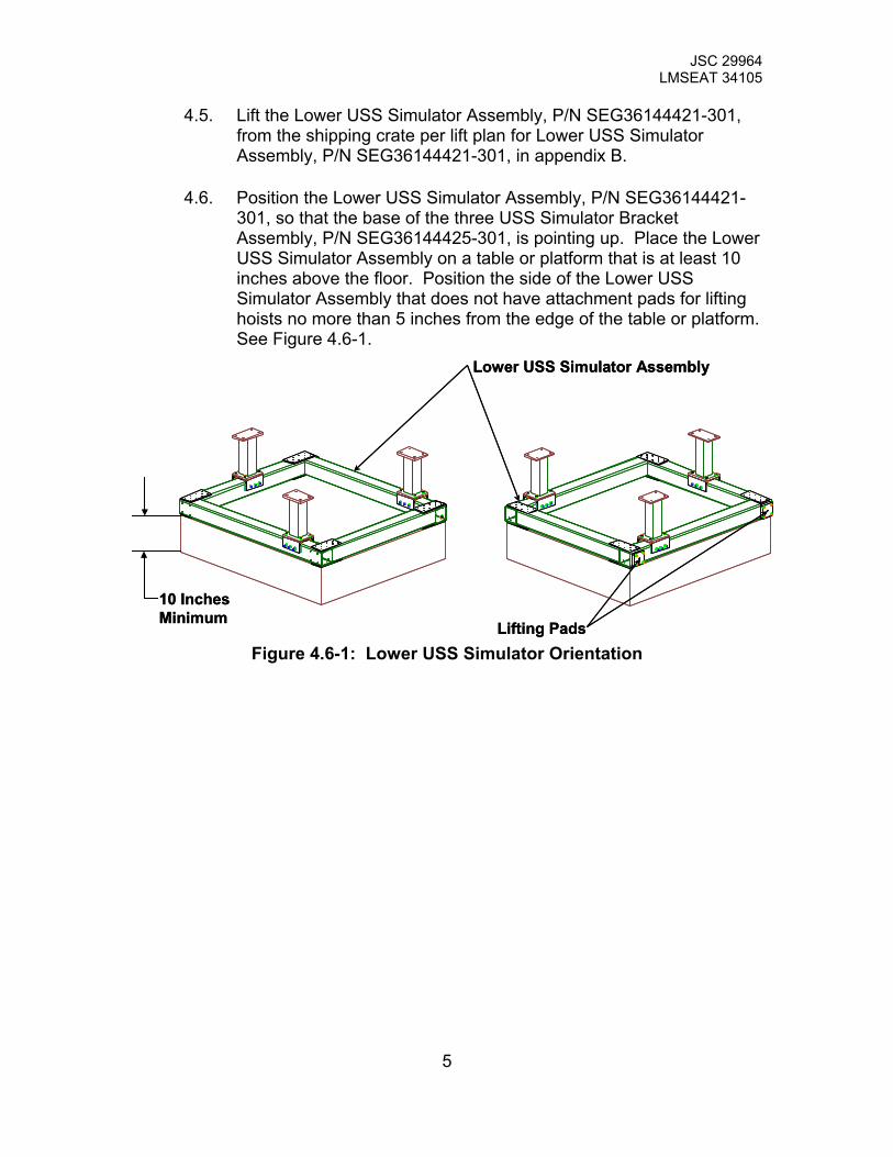
4.6. Position the Lower USS Simulator Assembly, P/N SEG36144421-301, so that the base of the three USS Simulator Bracket Assembly, P/N SEG36144425-301, is pointing up. Place the Lower USS Simulator Assembly on a table or platform that is at least 10 inches above the floor. Position the side of the Lower USS Simulator Assembly that does not have attachment pads for lifting hoists no more than 5 inches from the edge of the table or platform. See Figure 4.6-1.
Lifting Pads
10 InchesMinimum
Lower USS Simulator Assembly
Lifting Pads
10 InchesMinimum
Lower USS Simulator Assembly
Figure 4.6-1: Lower USS Simulator Orientation
5

JSC 29964 LMSEAT 34105
4.7. Place a Shim, P/N SDG36144438-007 and -009, on top of each of the USS Simulator Bracket Assembly, P/N SEG36144425-301 and –303. Match the hole patterns on each of the shims to each of the brackets. Use Kapton tape to secure the shims to the brackets. Mark on the surface of the brackets and the shims with a black sharpie to avoid mismatch at a later point in time. See Figure 4.7-1
Shim
Isolator
Shim
Isolator
Figure 4.7-1: USS Simulator Bracket Assembly Shims and Isolators
4.8. Place an Isolator, P/N SDG36144438-011 and –013, on top of each of the Shim, P/N SDG36144438-007 and –009. Match the hole patterns on each of the isolators to each of the shims. See Figure 4.7-1
4.9. Install the Lifting Plate, P/N SDG36144432-001, to the AMS-02 Passive PAS Assembly, P/N SEG39135815-301. The boss on the Lifting Plate fits in the through hole on the sidewall of the AMS-02 Passive PAS Assembly. Secure the Lifting Plate with 2 NAS1003-9 .190-32UNJF-3A X 1.043 long hex head bolt and 2 .190-32UNJF-3B hex nut. The torque values are 34 to 41 in-lbs. Running/locking torque is 2-18 in-lbs. See Figure 4.9-1.
Lifting PlateFasteners
Lifting Plate
Lifting PlateFasteners
Lifting Plate
Figure 4.9-1: Lifting Plate Installation
6

JSC 29964 LMSEAT 34105
4.10. Label the pin hole identification on the Vertex and Rear Bridge Assembly of the AMS-02 Passive PAS Assembly, P/N SEG39135815-301. Place a piece of Kapton Tape on the Bridge Assembly near the holes. Using a sharpie label the pin hole ID per figure 4.10-1. Repeat for all four hole sets. The distance between each hole location is ¼ of an inch.
Detail APin Locations
Detail A
Detail APin Locations
Detail A
Figure 4.10-1 Pin Hole Identification
7

JSC 29964 LMSEAT 34105
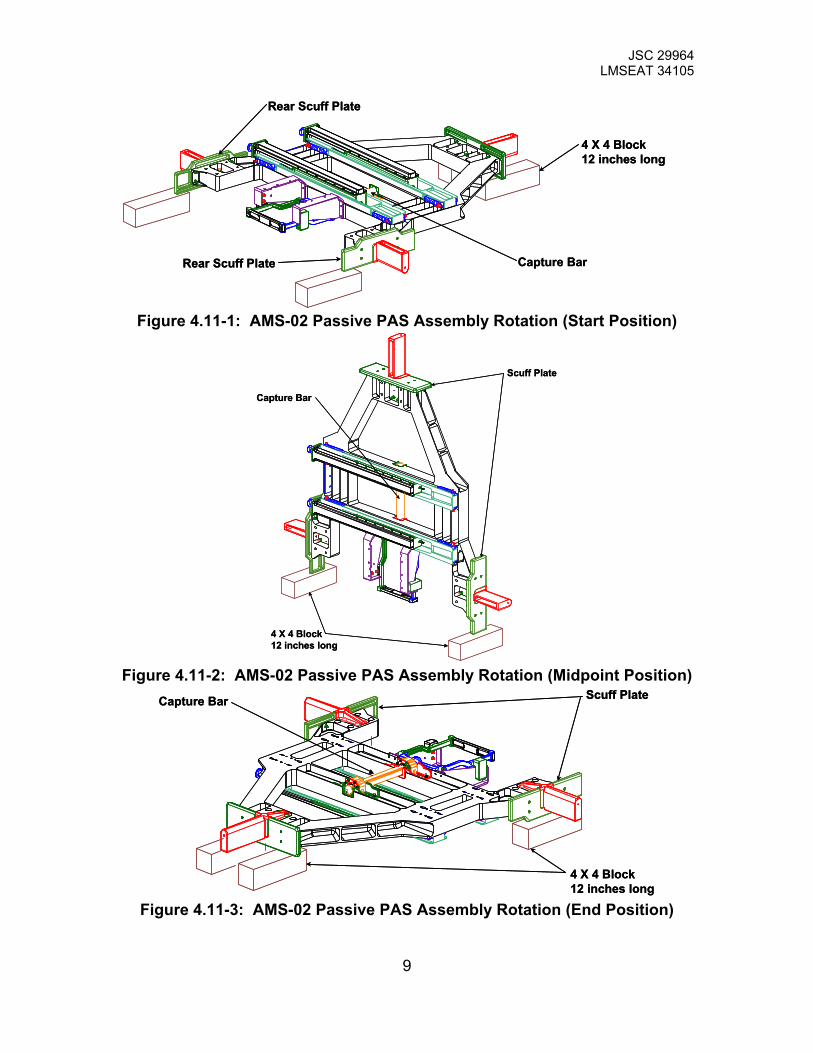
4.11. If the AMS-02 Passive PAS Assembly, P/N SEG39135815-301, arrives in the container with the Capture Bar facing up (Figure 4.11-3), skip to the next step. Remove the AMS-02 Passive PAS Assembly from the shipping crate per lifting plan in Appendix C Lift Plan. The AMS-02 Passive PAS Assembly weighs approximately 170 lbs and will require 4 people to lift the assembly. Place the assembly on wooden 4x4 blocks that are about one foot in length and surrounded by rubber padding. The rubber padding will prevent the blocks from slipping. The 4x4 blocks need to be placed underneath the Scuff Plates. The 4x4 blocks placed under the rear scuff plates needs to be positioned to allow the top surface of the rear scuff plates to come to rest when the AMS-02 Passive PAS Assembly is rotated 180 degrees. Rotate the AMS-02 Passive PAS Assembly until the Capture Bar faces up. See Figure 4.11-1,2, and 3 for the rotation sequence. During rotation of the AMS-02 Passive PAS Assembly, always maintain physical contact and do not allow the AMS-02 Passive PAS Assembly to fall or touch the ground.
8
JSC 29964 LMSEAT 34105
4 X 4 Block12 inches long
Rear Scuff Plate Capture Bar
Rear Scuff Plate
4 X 4 Block12 inches long
Rear Scuff Plate Capture Bar
Rear Scuff Plate
Figure 4.11-1: AMS-02 Passive PAS Assembly Rotation (Start Position)
4 X 4 Block12 inches long
Scuff Plate
Capture Bar
4 X 4 Block12 inches long
Scuff Plate
Capture Bar
Figure 4.11-2: AMS-02 Passive PAS Assembly Rotation (Midpoint Position)
4 X 4 Block12 inches long
Scuff PlateCapture Bar
4 X 4 Block12 inches long
Scuff PlateCapture Bar
Figure 4.11-3: AMS-02 Passive PAS Assembly Rotation (End Position)
9
JSC 29964 LMSEAT 34105
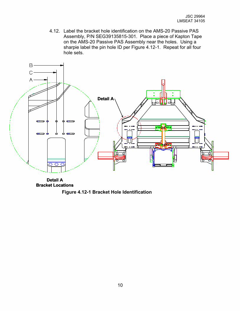
4.12. Label the bracket hole identification on the AMS-20 Passive PAS Assembly, P/N SEG39135815-301. Place a piece of Kapton Tape on the AMS-20 Passive PAS Assembly near the holes. Using a sharpie label the pin hole ID per Figure 4.12-1. Repeat for all four hole sets.
Detail ABracket Locations
Detail A
Detail ABracket Locations
Detail A
Figure 4.12-1 Bracket Hole Identification
10

JSC 29964 LMSEAT 34105
4.13. Check to insure that an Isolator, P/N SDG36144438-011 and –013, has been placed on top of the Shims, P/N SDG36144438-007 and –009. Lift the AMS-02 Passive PAS Assembly, P/N SEG39135815-301, per lift plan in appendix C. Place the mating surfaces of the AMS-02 Passive PAS Assembly, which is facing the ground, on top of the mating surfaces of the Lower USS Simulator Assembly, P/N SEG36144421-301. The AMS-02 Passive PAS weighs about 170 lbs and requires four people for lifting. Match the mounting surface on the AMS-02 Passive PAS Assembly to the mounting surface on the USS Bracket Simulator Assembly, P/N SEG36144425-301 and –303. See Figure 4.13-1 and 4.13-2. Do not allow the AMS-02 Passive PAS to contact the Lower USS Simulator Assembly.
Mating Surface Mating Surface
Mating Surface
Mating Surface Mating Surface
Mating Surface Figure 4.13-1: AMS-02 Passive PAS Assembly Mating Surface
Mating Surface
Mating Surface
Mating Surface Mating Surface
Mating Surface
Mating Surface
Figure 4.13-2: Lower USS Simulator Assembly Mating Surface
11
JSC 29964 LMSEAT 34105
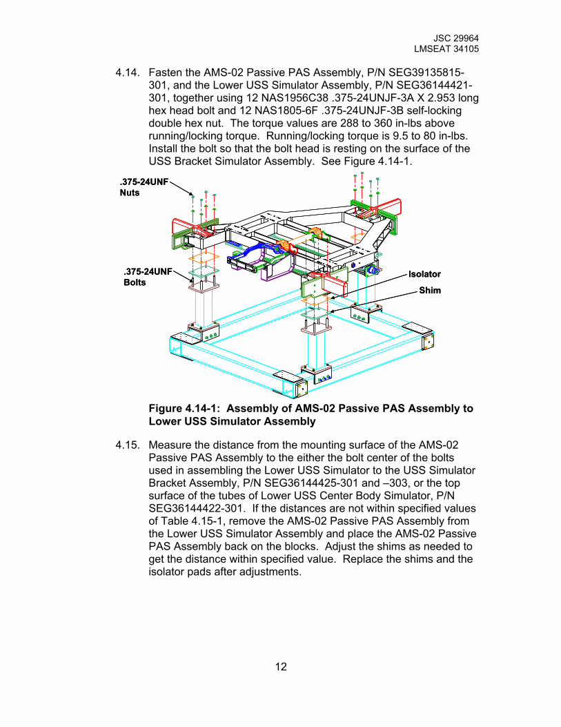
4.14. Fasten the AMS-02 Passive PAS Assembly, P/N SEG39135815-301, and the Lower USS Simulator Assembly, P/N SEG36144421-301, together using 12 NAS1956C38 .375-24UNJF-3A X 2.953 long hex head bolt and 12 NAS1805-6F .375-24UNJF-3B self-locking double hex nut. The torque values are 288 to 360 in-lbs above running/locking torque. Running/locking torque is 9.5 to 80 in-lbs. Install the bolt so that the bolt head is resting on the surface of the USS Bracket Simulator Assembly. See Figure 4.14-1.
Shim
.375-24UNFBolts
Isolator
.375-24UNFNuts
Shim
.375-24UNFBolts
Isolator
.375-24UNFNuts
Figure 4.14-1: Assembly of AMS-02 Passive PAS Assembly to Lower USS Simulator Assembly
4.15. Measure the distance from the mounting surface of the AMS-02 Passive PAS Assembly to the either the bolt center of the bolts used in assembling the Lower USS Simulator to the USS Simulator Bracket Assembly, P/N SEG36144425-301 and –303, or the top surface of the tubes of Lower USS Center Body Simulator, P/N SEG36144422-301. If the distances are not within specified values of Table 4.15-1, remove the AMS-02 Passive PAS Assembly from the Lower USS Simulator Assembly and place the AMS-02 Passive PAS Assembly back on the blocks. Adjust the shims as needed to get the distance within specified value. Replace the shims and the isolator pads after adjustments.
12

JSC 29964 LMSEAT 34105
Table 4.15-1: Required Distance Between Mounting Surface and USS Simulator Assembly
Rear Bracket Assembly SEG36144425-301
Vertex Bracket Assembly SEG36144425-303
Bolt Center 13.22 inches +/- .01 inches 13.22 inches +/- .01 inches
Tube Top Surface 15.97 inches +/- .01 inches 15.97 inches +/- .01 inches
4.16. Install the Mounting Plate on the underside of bridge of the Test Frame Assembly, P/N SEG36144427-301. Secure the Mounting Plate with 4 NAS1008-9 .500-20UNJF-3A X1.404 long bolts. Use oversized washer 1.5 inch OD, P/N 90313A117, with the .500 inch fasteners. Apply SBT-8 Anti Seize Lubricant to the fastener and torque the fasteners between 387 and 455 in-lbs above running/locking torque. See Figure 4.16-1
.500-20UNFFastener
MountingPlate
.500-20UNFFastener
MountingPlate
Figure 4.16-1: Mounting Plate Installation
4.17. Inspect the Load Rod, P/N SDG36144418-001, and the hex nuts, P/N SDG36144420-001 and –003, for nicks, cuts, scratch, and debris. Clean the debris and chase the threads if the engineer determines that the nicks, cuts, and scratches will gall the threads of the mating part.
13
JSC 29964 LMSEAT 34105
4.18. Install the Interface model 1220 25K Load Cell onto the Load Rod, P/N SDG36144418-001. Apply SBT-8 Anti Seize Lubricant to the Load Rod and torque Load Rod to hand tight plus 1/6th of a turn. .
4.19. Inspect the threads on the Clevis, P/N SDG36144417-001, for nicks, cuts, scratch, and debris. Clean the debris and the threads if the engineer determines that the nicks, cuts, and scratches will gall threads of the mating part.
4.20. Install the Clevis, P/N SDG36144417-001, to the Interface model 1220 25K Load Cell. Apply SBT-8 Anti Seize Lubricant to the Clevis and torque Clevis to hand tight plus 1/6th of a turn.
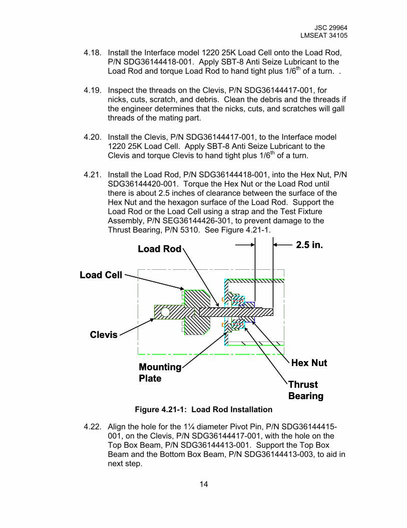
4.21. Install the Load Rod, P/N SDG36144418-001, into the Hex Nut, P/N SDG36144420-001. Torque the Hex Nut or the Load Rod until there is about 2.5 inches of clearance between the surface of the Hex Nut and the hexagon surface of the Load Rod. Support the Load Rod or the Load Cell using a strap and the Test Fixture Assembly, P/N SEG36144426-301, to prevent damage to the Thrust Bearing, P/N 5310. See Figure 4.21-1.
MountingPlate Thrust
Bearing
Hex Nut
Load Rod
Load Cell
Clevis
2.5 in.
MountingPlate Thrust
Bearing
Hex Nut
Load Rod
Load Cell
Clevis
2.5 in.
Figure 4.21-1: Load Rod Installation
4.22. Align the hole for the 1¼ diameter Pivot Pin, P/N SDG36144415-001, on the Clevis, P/N SDG36144417-001, with the hole on the Top Box Beam, P/N SDG36144413-001. Support the Top Box Beam and the Bottom Box Beam, P/N SDG36144413-003, to aid in next step.
14
JSC 29964 LMSEAT 34105
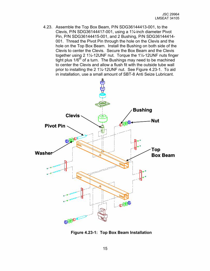
4.23. Assemble the Top Box Beam, P/N SDG36144413-001, to the Clevis, P/N SDG36144417-001, using a 1¼-inch diameter Pivot Pin, P/N SDG36144415-001, and 2 Bushing, P/N SDG36144414-001. Thread the Pivot Pin through the hole on the Clevis and the hole on the Top Box Beam. Install the Bushing on both side of the Clevis to center the Clevis. Secure the Box Beam and the Clevis together using 2 1¼-12UNF nut. Torque the 1¼-12UNF nuts finger tight plus 1/6th of a turn. The Bushings may need to be machined to center the Clevis and allow a flush fit with the outside tube wall prior to installing the 2 1¼-12UNF nut. See Figure 4.23-1. To aid in installation, use a small amount of SBT-8 Anti Seize Lubricant.
Washer
Nut
Bushing
Pivot Pin
Clevis
TopBox BeamWasher
Nut
Bushing
Pivot Pin
Clevis
TopBox Beam
Figure 4.23-1: Top Box Beam Installation
15

JSC 29964 LMSEAT 34105
4.24. If the Top and Bottom Box Beam, P/N SDG36144413-001 and –003, are assembled skip to next step. Assemble Bottom Box Beam, P/N SDG36144413-003, to Top Box Beam, P/N SDG36144413-001, using 4 Pivot Plates, P/N SDG36144416-001; 4 Pivot Pin, P/N SDG36144415-003; and 8 .375-24UNF nuts. Torque the .375-24UNF nuts finger tight plus 1/6th of a turn. See Figure 4.24-1. To aid in installation, use a small amount of SBT-8 Anti Seize Lubricant.
TopBox Beam
BottomBox Beam
Pivot Pin
Pivot Plate
.375-24UNF NUTS
TopBox Beam
BottomBox Beam
Pivot Pin
Pivot Plate
.375-24UNF NUTS
Figure 4.24-1: Bottom Box Beam Installation
16
JSC 29964 LMSEAT 34105
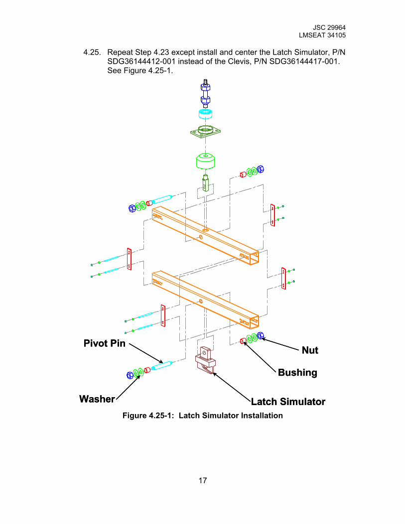
4.25. Repeat Step 4.23 except install and center the Latch Simulator, P/N SDG36144412-001 instead of the Clevis, P/N SDG36144417-001. See Figure 4.25-1.
Washer
Nut
Bushing
Pivot Pin
Latch SimulatorWasher
Nut
Bushing
Pivot Pin
Latch Simulator
Figure 4.25-1: Latch Simulator Installation
17
JSC 29964 LMSEAT 34105
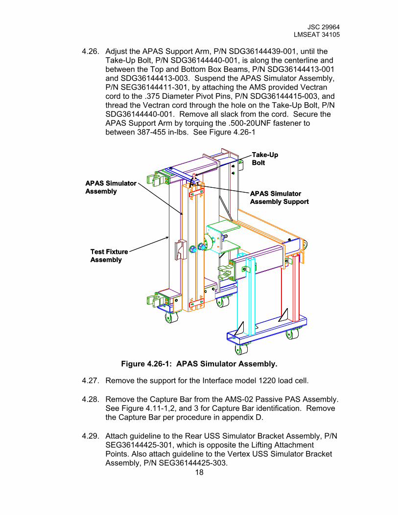
4.26. Adjust the APAS Support Arm, P/N SDG36144439-001, until the Take-Up Bolt, P/N SDG36144440-001, is along the centerline and between the Top and Bottom Box Beams, P/N SDG36144413-001 and SDG36144413-003. Suspend the APAS Simulator Assembly, P/N SEG36144411-301, by attaching the AMS provided Vectran cord to the .375 Diameter Pivot Pins, P/N SDG36144415-003, and thread the Vectran cord through the hole on the Take-Up Bolt, P/N SDG36144440-001. Remove all slack from the cord. Secure the APAS Support Arm by torquing the .500-20UNF fastener to between 387-455 in-lbs. See Figure 4.26-1
APAS SimulatorAssembly
Test FixtureAssembly
APAS SimulatorAssembly Support
Take-UpBolt
APAS SimulatorAssembly
Test FixtureAssembly
APAS SimulatorAssembly Support
Take-UpBolt
Figure 4.26-1: APAS Simulator Assembly.
4.27. Remove the support for the Interface model 1220 load cell.
4.28. Remove the Capture Bar from the AMS-02 Passive PAS Assembly. See Figure 4.11-1,2, and 3 for Capture Bar identification. Remove the Capture Bar per procedure in appendix D.
18
4.29. Attach guideline to the Rear USS Simulator Bracket Assembly, P/N SEG36144425-301, which is opposite the Lifting Attachment Points. Also attach guideline to the Vertex USS Simulator Bracket Assembly, P/N SEG36144425-303.
JSC 29964 LMSEAT 34105
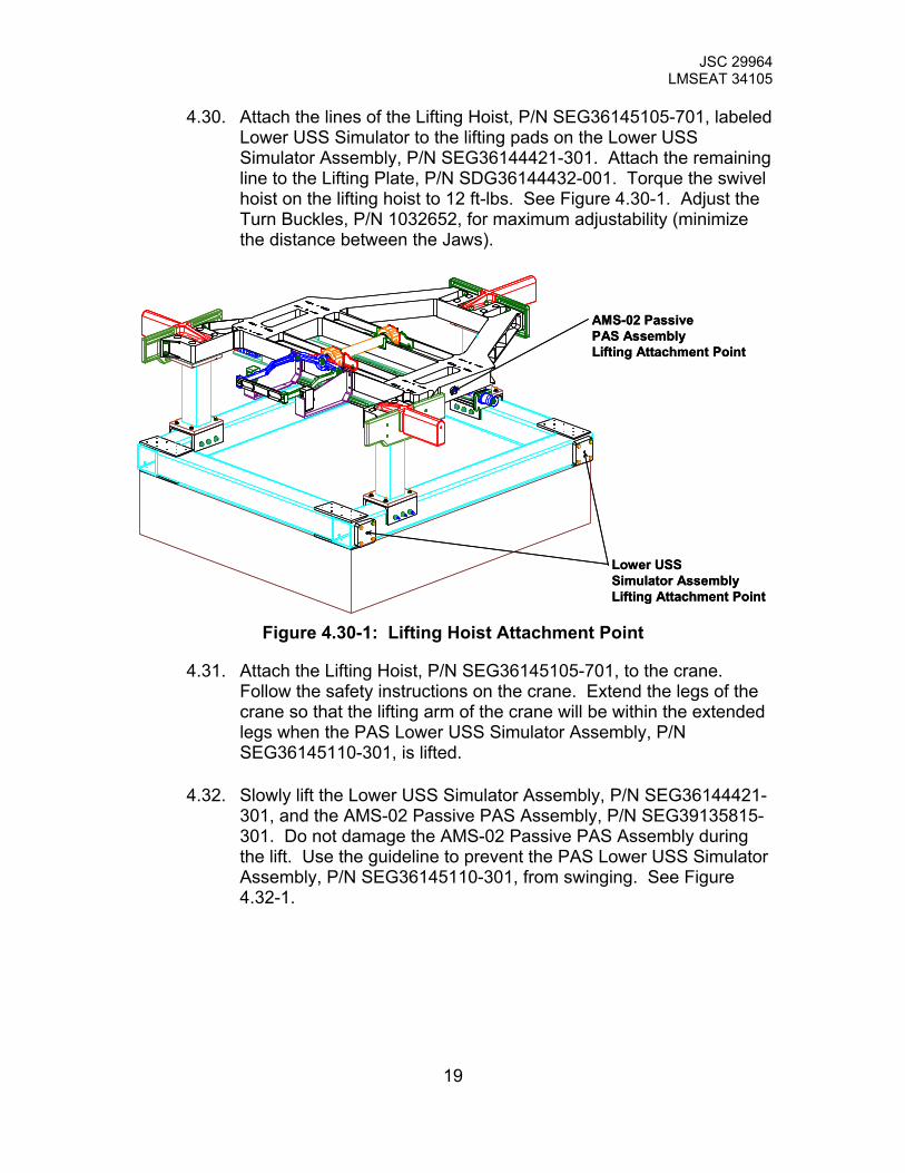
4.30. Attach the lines of the Lifting Hoist, P/N SEG36145105-701, labeled Lower USS Simulator to the lifting pads on the Lower USS Simulator Assembly, P/N SEG36144421-301. Attach the remaining line to the Lifting Plate, P/N SDG36144432-001. Torque the swivel hoist on the lifting hoist to 12 ft-lbs. See Figure 4.30-1. Adjust the Turn Buckles, P/N 1032652, for maximum adjustability (minimize the distance between the Jaws).
Lower USSSimulator AssemblyLifting Attachment Point
AMS-02 PassivePAS AssemblyLifting Attachment Point
Lower USSSimulator AssemblyLifting Attachment Point
AMS-02 PassivePAS AssemblyLifting Attachment Point
Figure 4.30-1: Lifting Hoist Attachment Point
4.31. Attach the Lifting Hoist, P/N SEG36145105-701, to the crane. Follow the safety instructions on the crane. Extend the legs of the crane so that the lifting arm of the crane will be within the extended legs when the PAS Lower USS Simulator Assembly, P/N SEG36145110-301, is lifted.
4.32. Slowly lift the Lower USS Simulator Assembly, P/N SEG36144421-301, and the AMS-02 Passive PAS Assembly, P/N SEG39135815-301. Do not damage the AMS-02 Passive PAS Assembly during the lift. Use the guideline to prevent the PAS Lower USS Simulator Assembly, P/N SEG36145110-301, from swinging. See Figure 4.32-1.
19

JSC 29964 LMSEAT 34105
Lower USSSimulatorAssembly
AMS-02 PassivePAS Assembly
Lifting Hoist
Guide Rope
Guide Rope
Lower USSSimulatorAssembly
AMS-02 PassivePAS Assembly
Lifting Hoist
Guide Rope
Guide Rope
Figure 4.32-1: Lifting
4.33. Use a 24-inch level to measure the AMS-02 Passive PAS Assembly, P/N SEG39135815-301. Adjust the Turn Buckles, P/N 1032652, to level the assembly in the X, Y, and Z.
4.34. Move the table that the AMS-02 Passive PAS Assembly was sitting on. Move the Test Fixture Assembly, P/N SEG36144426-301, to the suspended AMS-02 Passive PAS Assembly. Lock the Casters on the Test Fixture Assembly when the engineers have determined that the AMS-02 Passive PAS Assembly is close enough to the Test Fixture Assembly.
4.35. Position the AMS-02 Passive PAS so that the Guide Pins will sit in the Guide Vane Simulators, P/N SDG36144434-30X. Slowly move the AMS-02 PAS into the Guide Vane Simulators, P/N SDG36144434-30X. The gap between the Scuff Plates and the Guide Vane Simulator Assemblies are in Table 4.35-1. See Figure 4.1-1 for Guide Vane Simulator Designation.
20
JSC 29964 LMSEAT 34105
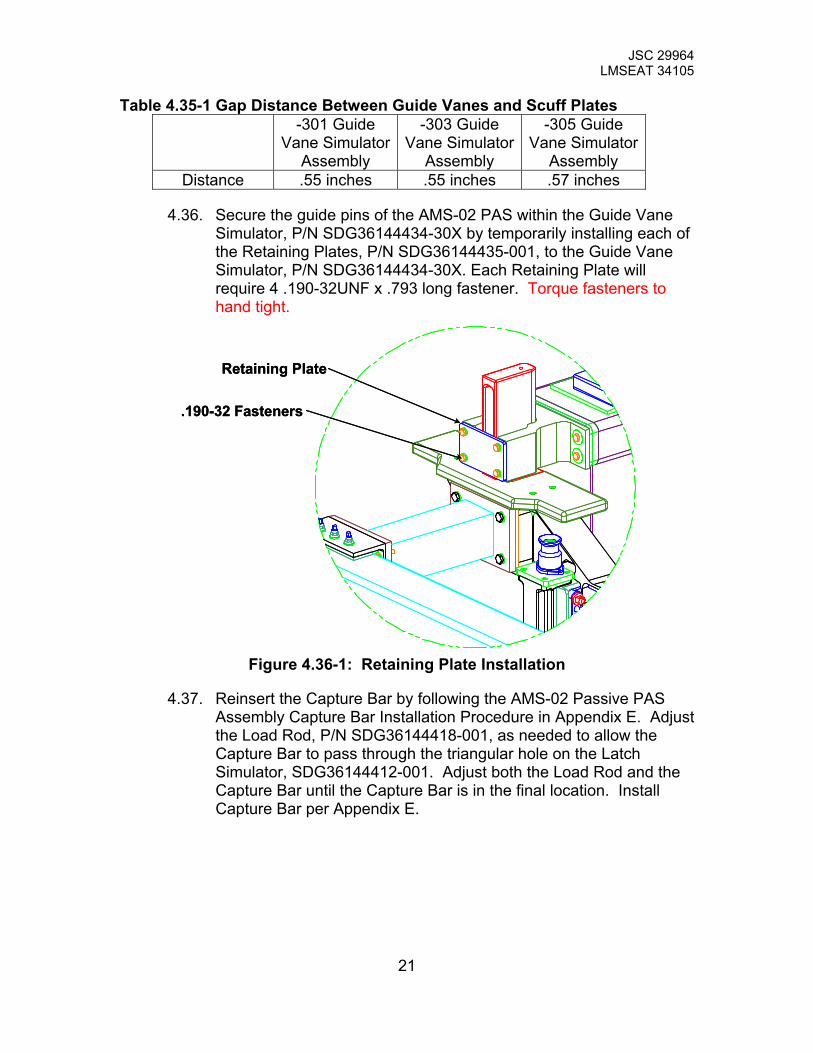
Table 4.35-1 Gap Distance Between Guide Vanes and Scuff Plates -301 Guide
Vane Simulator Assembly
-303 Guide Vane Simulator
Assembly
-305 Guide Vane Simulator
Assembly Distance .55 inches .55 inches .57 inches
4.36. Secure the guide pins of the AMS-02 PAS within the Guide Vane Simulator, P/N SDG36144434-30X by temporarily installing each of the Retaining Plates, P/N SDG36144435-001, to the Guide Vane Simulator, P/N SDG36144434-30X. Each Retaining Plate will require 4 .190-32UNF x .793 long fastener. Torque fasteners to hand tight.
Retaining Plate
.190-32 Fasteners
Retaining Plate
.190-32 Fasteners
Figure 4.36-1: Retaining Plate Installation
4.37. Reinsert the Capture Bar by following the AMS-02 Passive PAS Assembly Capture Bar Installation Procedure in Appendix E. Adjust the Load Rod, P/N SDG36144418-001, as needed to allow the Capture Bar to pass through the triangular hole on the Latch Simulator, SDG36144412-001. Adjust both the Load Rod and the Capture Bar until the Capture Bar is in the final location. Install Capture Bar per Appendix E.
21

JSC 29964 LMSEAT 34105
4.38. Install the Sensor Frame, P/N SEG36145111-301, to the Test Fixture Assembly, P/N SEG36144426-301. Install the 3 sides of the Sensor Frame first. See Figure 4.37-1. Attach the sides to the Guide Vane Simulator, P/N SDG36144434-30X, using .190-32UNF X 1.0 long socket head cap screws. See Figure 4.37-2. DO NOT damage the AMS-02 Passive PAS Assembly, P/N SEG39135815-301, during installation of the Sensor Frame.
Side 1
Side 2
Side 3
Side 1
Side 2
Side 3
Figure 4.37-1: Sensor Frame
Guide VaneSimulator
Sensor FrameSide 1
FastenerThru Hole
Guide VaneSimulator
Sensor FrameSide 1
FastenerThru Hole
Figure 4.37-2: Sensor Frame Interface
22

JSC 29964 LMSEAT 34105
4.39. Install the remaining Bridge Channels, P/N SDG36145111-003, and Sensor Channels, P/N SDG36145111-007, to complete the Sensor Frame, P/N SEG36145111-301 per drawing SEG36145111-301. See Figure 4.39-1. DO NOT damage the AMS-02 Passive PAS Assembly, P/N SEG39135815-301, during installation. Adjust the Sensor Channels as needed to meet the sensor requirements of section 5.0. See Figure 4.39-2 for a completed PAS Static Test Assembly
SensorChannel
BridgeChannel
SensorChannel
BridgeChannel
Figure 4.39-1: Bridge and Sensor Channel Installation
Lifting Hoist
AMS-02 PassivePAS Assembly
Lower USS SimulatorAssembly
Test FixtureAssembly
APAS SimulatorAssembly
Sensor Frame
Lifting Hoist
AMS-02 PassivePAS Assembly
Lower USS SimulatorAssembly
Test FixtureAssembly
APAS SimulatorAssembly
Sensor Frame
23 Figure 4.39-2: PAS Static Test Assembly

JSC 29964 LMSEAT 34105
5.0 Test Instrumentation
5.1. The PAS will require the following instrumentation (see Table 5.1-1 for a list of gages): • 8 Deflection gages
o Accuracy of +/- 1.0% of expected deflection. o Resolution of +/- 0.005 inches.
• 8 Triaxial Strain gages • 1 Load Cell
Table 5.1-1 Summary of Strain and Deflection Gages Location Descirption Sensor Type QTY Sensor ID Channel
PAS Base Assembly See Figure 5.4-1 Rosette 1 1 3
PAS Base Assembly See Figure 5.4-2 Rosette 1 2 3
PAS Base Assembly See Figure 5.4-3 Rosette 1 3 3
PAS Base Assembly See Figure 5.4-1, 2 Rosette 1 4 3
PAS Base Assembly See Figure 5.4-1, 2 Rosette 1 5 3
PAS Base Assembly See Figure 5.4-3 Rosette 1 6 3
Vertex Bridge Assembly See Figure 5.4-4 and 5 Rosette 1 7* 3
Rear Bridge Assembly See Figure 5.4-4 and 5 Rosette 1 8* 3
Sub-Total 8 24
Capture Bar Center of Capture Bar Deflection Gage 1 A 1
Capture Bar Rear end of Capture Bar Deflection Gage 1 B 1
Capture Bar Vertex end of Capture Bar Deflection Gage 1 C 1
PAS Platform Assembly See Figure 5.4-6 Deflection Gage 1 D 1
PAS Platform Assembly See Figure 5.4-6 Deflection Gage 1 E 1
Bridge Pin Rear end of Vertex +Y Bridge Pin Deflection Gage 1 F 1
Bridge Pin Rear end of Vertex -Y Bridge Pin Deflection Gage 1 G 1
Bridge Pin Vertex end of Rear -Y Bridge Pin Deflection Gage 1 H 1
Bridge Pin Vertex end of Rear +Y Bridge Pin Deflection Gage 1 J 1
Load Cell Mounting Surface of Load Cell Deflection Gage 1 K 1
Sub-Total 10 10 APAS Simulator Assembly
Connection between Load Rod and Clevis Load Cell 1 L1 1
Sub-Total 1 1
Total 19 35
*This gage will be bonded to a nickel plated surface
24
JSC 29964 LMSEAT 34105
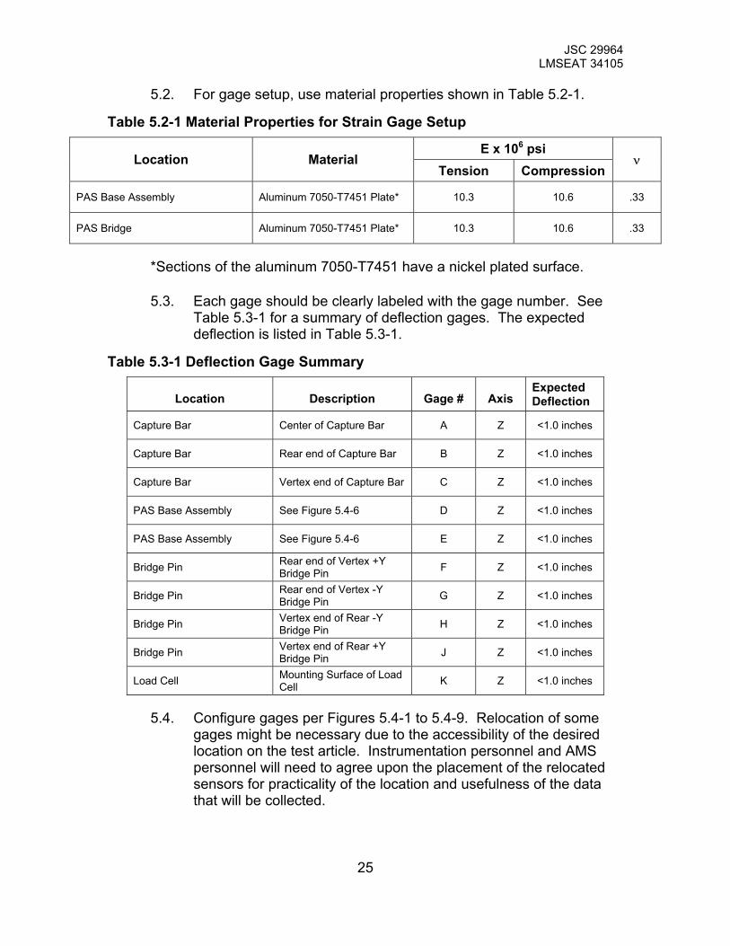
5.2. For gage setup, use material properties shown in Table 5.2-1.
Table 5.2-1 Material Properties for Strain Gage Setup
E x 106 psi Location Material
Tension Compressionν
PAS Base Assembly Aluminum 7050-T7451 Plate* 10.3 10.6 .33
PAS Bridge Aluminum 7050-T7451 Plate* 10.3 10.6 .33
*Sections of the aluminum 7050-T7451 have a nickel plated surface.
5.3. Each gage should be clearly labeled with the gage number. See Table 5.3-1 for a summary of deflection gages. The expected deflection is listed in Table 5.3-1.
Table 5.3-1 Deflection Gage Summary
Location
Description
Gage #
Axis Expected Deflection
Capture Bar Center of Capture Bar A Z <1.0 inches
Capture Bar Rear end of Capture Bar B Z <1.0 inches
Capture Bar Vertex end of Capture Bar C Z <1.0 inches
PAS Base Assembly See Figure 5.4-6 D Z <1.0 inches
PAS Base Assembly See Figure 5.4-6 E Z <1.0 inches
Bridge Pin Rear end of Vertex +Y Bridge Pin F Z <1.0 inches
Bridge Pin Rear end of Vertex -Y Bridge Pin G Z <1.0 inches
Bridge Pin Vertex end of Rear -Y Bridge Pin H Z <1.0 inches
Bridge Pin Vertex end of Rear +Y Bridge Pin J Z <1.0 inches
Load Cell Mounting Surface of Load Cell K Z <1.0 inches
5.4. Configure gages per Figures 5.4-1 to 5.4-9. Relocation of some gages might be necessary due to the accessibility of the desired location on the test article. Instrumentation personnel and AMS personnel will need to agree upon the placement of the relocated sensors for practicality of the location and usefulness of the data that will be collected.
25

JSC 29964 LMSEAT 34105
26 Figure 5.4-1: Strain Gage 1, 4, and 5 Location
Detail B
Detail BStrain Gage 4 and 5
Gage 5 located along center line of pockets inPAS Platform and flush against bottom surface
Detail A
Detail AStrain Gage 1
Gage 4Flush against bottom surface
Gage 1Flush againsttop surface
Detail B
Detail BStrain Gage 4 and 5
Gage 5 located along center line of pockets inPAS Platform and flush against bottom surface
Detail A
Detail AStrain Gage 1
Gage 4Flush against bottom surface
Gage 1Flush againsttop surface

JSC 29964 LMSEAT 34105
27 Figure 5.4-2: Strain Gage 2, 4, and 5 Location
Detail CStrain Gage 2, 4, and 5
Gage 5See Detail Bof Figure 5.4-1
Gage 4See Detail Bof Figure 5.4-1
Detail C
Gage 2Flush againstbottom surface
Detail CStrain Gage 2, 4, and 5
Gage 5See Detail Bof Figure 5.4-1
Gage 4See Detail Bof Figure 5.4-1
Detail C
Gage 2Flush againstbottom surface

JSC 29964 LMSEAT 34105
28 Figure 5.4-3: Strain Gage 3 and 6 Location
Detail EStrain Gage 6
Detail D
Detail DStrain Gage 3
Detail E
Gage 3Flush against bottom surface
Gage 6Flush againstbottom surface
Detail EStrain Gage 6
Detail D
Detail DStrain Gage 3
Detail E
Gage 3Flush against bottom surface
Gage 6Flush againstbottom surface

JSC 29964 LMSEAT 34105
29 Figure 5.4-4: Strain Gage 7 and 8 Location
Gage 8
Detail FDetail G
Detail FStrain Gage 7
Detail GStrain Gage 8
Gage 7

JSC 29964 LMSEAT 34105
30 Figure 5.4-5: Strain Gage 7 and 8 Location Detail
Detail H
Gage 7 and 8 located along X axis of through hole forBearing Housing. Place gage as close to the edge ofthrough hole for Bearing Housing as possible
Detail HStrain Gage 7 and 8
Detail H
Gage 7 and 8 located along X axis of through hole forBearing Housing. Place gage as close to the edge ofthrough hole for Bearing Housing as possible
Detail HStrain Gage 7 and 8

JSC 29964 LMSEAT 34105
31 Figure 5.4-6: Deflection Gage A, B, C, D, and E Location
Gage A
Gage B
Gage C
Gage D
Gage E
Note: All Deflection Gages measure displacement in the+Z direction
Gage A
Gage B
Gage C
Gage D
Gage E
Note: All Deflection Gages measure displacement in the+Z direction

JSC 29964 LMSEAT 34105
32 Figure 5.4-7: Deflection Gage B, C, D, and E Location
Detail IDeflection Gage B
Detail JDeflection Gage C
Gage B
Gage C
Detail I
Detail JDeflection Gage ERemoved for Clarity
Deflection Gage EDeflection Gage D
Note: All Deflection Gages measure displacement in the+Z direction
Detail IDeflection Gage B
Detail JDeflection Gage C
Gage B
Gage C
Detail I
Detail JDeflection Gage ERemoved for Clarity
Deflection Gage EDeflection Gage D
Note: All Deflection Gages measure displacement in the+Z direction
JSC 29964 LMSEAT 34105
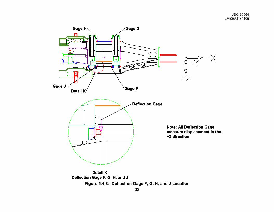
33 Figure 5.4-8: Deflection Gage F, G, H, and J Location
Detail KDeflection Gage F, G, H, and J
Deflection Gage
Detail K Gage F
Gage G
Gage J
Gage H
Note: All Deflection Gagemeasure displacement in the+Z direction
Detail KDeflection Gage F, G, H, and J
Deflection Gage
Detail K Gage F
Gage G
Gage J
Gage H
Note: All Deflection Gagemeasure displacement in the+Z direction

JSC 29964 LMSEAT 34105
34 Figure 5.4-9: Deflection Gage K Location
DeflectionGage K
DeflectionGage K
DeflectionGage K
Note: All Deflection Gagemeasure displacement in the+Z direction
DeflectionGage K
DeflectionGage K
DeflectionGage K
Note: All Deflection Gagemeasure displacement in the+Z direction

JSC 29964 LMSEAT 34105
6.0 Data Requirements Test lab personnel shall coordinate and deliver the following data:
6.1. Photographic documentation (digital and conventional still camera) of the test set-up and gage location is required. These photos should show the gages orientation and the gage number labels.
6.2. Strain versus percent load for each strain gage.
6.3. Deflection versus load for each deflection gage.
6.4. Real time readouts of gages 1, 7, 8, A, B and C data channel on a display monitor for the Test Engineer and Stress Analyst. If possible, real time readouts of all gages for Stress Analyst.
6.5. Real time graphical plots of gages 1, 7, 8, A, B and C data channel on a separate display monitor for the Test Engineer and Stress Analyst.
6.6. Numerical data should be delivered in hard copy and in electronic (ASCII or EXCEL file) format.
6.7. Test Data Package including test notes, control documentation, instrumentation, test data and other applicable data.
35
JSC 29964 LMSEAT 34105
7.0 Test Procedure
7.1. Stiffness Calibration Test Procedure
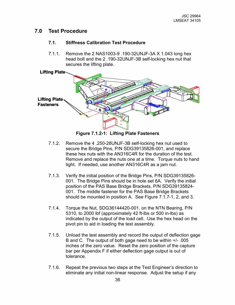
7.1.1. Remove the 2 NAS1003-9 .190-32UNJF-3A X 1.043 long hex head bolt and the 2 .190-32UNJF-3B self-locking hex nut that secures the lifting plate.
Lifting PlateFasteners
Lifting Plate
Lifting PlateFasteners
Lifting Plate
Figure 7.1.2-1: Lifting Plate Fasteners
7.1.2. Remove the 4 .250-28UNJF-3B self-locking hex nut used to secure the Bridge Pins, P/N SDG39135826-001, and replace these hex nuts with the AN316C4R for the duration of the test. Remove and replace the nuts one at a time. Torque nuts to hand tight. If needed, use another AN316C4R as a jam nut.
7.1.3. Verify the initial position of the Bridge Pins, P/N SDG39135826-001. The Bridge Pins should be in hole set 6A. Verify the initial position of the PAS Base Bridge Brackets, P/N SDG39135824-001. The middle fastener for the PAS Base Bridge Brackets should be mounted in position A. See Figure 7.1.7-1, 2, and 3.
7.1.4. Torque the Nut, SDG36144420-001, on the NTN Bearing, P/N 5310, to 2000 lbf (approximately 42 ft-lbs or 500 in-lbs) as indicated by the output of the load cell. Use the hex head on the pivot pin to aid in loading the test assembly.
7.1.5. Unload the test assembly and record the output of deflection gage B and C. The output of both gage need to be within +/- .005 inches of the zero value. Reset the zero position of the capture bar per Appendix F if either deflection gage output is out of tolerance.
7.1.6. Repeat the previous two steps at the Test Engineer’s direction to eliminate any initial non-linear response. Adjust the setup if any
36

JSC 29964 LMSEAT 34105
problems arise during the loadings. Reset the zero position of the capture bar per Appendix F as required.
7.1.7. Repeat the previous 4 steps with the Bridge Pin, P/N SDG39135826-001, in hole set 1A of the vertex and the rear PAS Base Bridge Bracket, P/N SDG39135824-001. See Figure 7.1.7-1, 2, and 3 for pin location. When adjusting the location of the Bridge Pins, remove one Bridge Pin at one time. The Bridge Assembly, P/N SEG39135836-301, will need to be supported by hand during the relocation of the Bridge Pin. Secure the Bridge Pins with AN316C4R hex nut. If needed, use another AN316C4R hex nut as a jam nut to secure the Bridge Pins.
Vertex Bridge Beam
Rear Bridge Beam
Vertex Bridge Beam
Rear Bridge Beam
Figure 7.1.7-1: Pin Set Locations
37

JSC 29964 LMSEAT 34105
Detail ABracket Locations
Detail A
Detail ABracket Locations
Detail A
Figure 7.1.7-2: Bracket Set Locations
Detail BPin Locations
Detail B
Detail BPin Locations
Detail B
Figure 7.1.7-3: Stiffness Set Locations
38

JSC 29964 LMSEAT 34105
7.2. Stiffness Set Procedure
7.2.1. Set the Bridge Pins, SDG39135826-001, on the PAS Base Bridge Bracket, P/N SDG39135824-001, in the hole location that sets the stiffness of the AMS-02 Passive PAS Assembly, P/N SEG39135815-301, near the required stiffness. Torque the nuts to hand tight.
7.2.2. Torque the Nut, P/N SDG36144420-001, on the Bearing, P/N 5310, to 2000 lbf (approximately 42 ft-lbs or 500 in-lbs) as indicated by the output of the load cell.
7.2.3. Record the value of deflection gage A at a load cell output of 2000 lbf. Determine the stiffness of the AMS-02 Passive PAS Assembly, P/N SEG39135815-301, based on the collected information.
7.2.4. If the stiffness of the AMS-02 Passive PAS Assembly, P/N SEG39135815-301 is above the upper limit of 14850 lbf/in, move the Bridge Pins, SDG39135826-001, to a numerically lower hole location. If the stiffness of the AMS-02 Passive PAS Assembly is below the lower limit of 12150 lbf/in, move the Bridge Pins to a numerically higher hole location. Adjust Bridge Pins until the stiffness of the AMS-02 Passive PAS Assembly is within the specified values. If necessary, the PAS Base Bridge Bracket, P/N SDG39135824-001, can also be adjusted individually to get the required stiffness. Adjust the PAS Base Bridge Bracket by loosening the fasteners that secure the base of the bracket to the AMS-02 Passive PAS Assembly. Remove only the middle fasteners. Shift the PAS Base Bridge Bracket inward or outward as required. Tighten the fasteners between 83 to 97 in-lbs. The running/locking torque shall be between 3.0 to 40 in-lbs.
39

JSC 29964 LMSEAT 34105
Detail ABracket Locations
Detail A
Detail ABracket Locations
Detail A
Figure 7.2.4-1: Bracket Adjustment
7.2.5. Once the AMS-02 Passive PAS Assembly, P/N SEG39135815-301, is within the specified stiffness values. Check the output of deflection gage B and C while the system is still loaded with 2000 lbf. The difference between output of B and C need to be less than .036 inches. If the difference between the gage B and C is greater than .036 inches, adjust the PAS Base Bridge Bracket, P/N SDG39135824-001 per previous step.
7.2.6. Recheck the stiffness of the AMS-02 Passive PAS Assembly, P/N SEG39135815-301, if the PAS Base Bridge Bracket, P/N SDG39135824-001, were adjusted in the previous step. Repeat the previous 2 steps to get the stiffness and the deflection within specified values.
7.2.7. Check the values of deflection gage B and C. Repeat step 7.2.5 if the values are out off tolerance.
7.2.8. When the stiffness and deflections are within the specified values, load the AMS-02 Passive PAS Assembly, P/N SEG39135815-301, to 2000 lbf (approximately 42 ft-lbs or 500 in-lbs) as indicated by the output of the load cell.
40

JSC 29964 LMSEAT 34105
7.2.9. Record the output of deflection gage A and the load cell. Determine the stiffness of APAS Simulator Assembly, P/N SEG36144410-301, based of the output.
7.2.10. If the stiffness of the APAS Simulator Assembly, P/N SEG36144410-301, is above 24864 lbf/in move the Pivot Pins, P/N SDG36144415-001, outward. If the stiffness of the APAS Simulator Assembly is below 20989 lbf/in move the Pivot Pins inward.
7.2.11. Torque the Nut, P/N SDG36144420-001, on the Bearing, P/N 5310, to 6430 lbf (approximately 134 ft-lbs or 1608 in-lbs) as indicated by the output of the load cell
7.2.12. Lock the configuration in place by jamming the Hex Nut, P/N SDG36144427-003, if needed. Torque the top nut to 48 in-lbs above running/locking torque to lock the configuration.
7.2.13. Remove the capture bar per AMS-02 Passive PAS Assembly Capture Bar Removal procedure in appendix D.
7.2.14. Reinstall the capture bar per AMS-02 Passive PAS Assembly Capture Bar Installation procedure in appendix E.
7.2.15. Repeat Previous 3 Steps at the Test Engineer’s direction.
7.2.16. Unload the test setup.
7.2.17. Disassemble the test hardware per Test Engineer’s direction.
8.0 Pass/Fail Criteria The criterion for a successful test is no permanent deformation of the Flight hardware and the successful unloading and removal of the capture bar.
41

JSC 29964 LMSEAT 34105
9.0 Test Support Personnel from the test facility will assist the Lockheed Martin personnel in test setup and test operations. This test will involve Flight hardware and therefore, support from Quality Assurance personnel is required. A Test Readiness Review will be conducted prior to the test to review procedures and provide approval to proceed. The test review board, as a minimum, will consist of the following personnel. Other personnel may be added as needed. Table 9-1. Test Personnel
Responsibility Representative Contact
Test Engineer Hsing Ju / LMSO 281-333-7494
Test Lead Engineer Phil Mott / LMSO 281-333-6451
Project Manager Kenneth Bollweg / LMSO 281-335-2714
Structural Lead Trent Martin / LMSO 281-335-2139
Stress Lead Chittur Balasubramanian / LMSO 281-333-7518
Stress Analyst Howard Carter / LMSO 281-333-7339
PAS Design Engineer Joe Kastelic / LMSO 281-333-7352
Dynamics Analyst Chris Tutt / LMSO 281-333-7634
Safety Facility Representative -
Q.E. Facility Representative -
Instrumentation Facility Representative -
Chairperson Facility Representative -
42
JSC 29964 LMSEAT 34105
Appendix A: Boeing Stiffness Analysis FYI - here's the analysis THANKS, jjs John Scheerer Mechanical Systems Design International Space Station, Boeing-HB phone: (714) 896-3311 x71834 pager: (714) 691-3189 fax: (714) 896-5034 e-mail: [email protected] > -----Original Message----- > From: Simecka, Jay B > Sent: Tuesday, November 20, 2001 2:59 PM > To: Scheerer, John J > Subject: CAS Interface > > <<CAS Interface.doc>> > Jay Simecka > Mechanical Strength > X60699 >
A-1

JSC 29964 LMSEAT 34105
A-2
CAS Interface Analysis:Requirement of FEM analysis is that the interfaces could gap no more than .25 inches at ultimate loads andno gapping at 1.25 X limit loads.
Results of FEM analysis:
Nominal Preload: F preload 5650 lbfActive Half Stiffness: K a 46858lbfin
(+/- 12%)
Minimum preload reqmt (from FEA):
Passive Half Stiffness: K p 13500lbfin
(+/- 12%) F min 4900 lbf
Capture Latch Siffness: K cla 45000lbfin
(+/- 5%)
Capture Latch Mounting Face to Capture Bar under 4700 lbf load Distance:(per acceptance test)
l clapreload 4.00 in Tolerance: t cla4700 .018 in total
Active platform tolerance due to final shimming: t platform .005 in total
Guide Vane Mounting Face to Guide Vane/pin interface Distance: l gv 3.397 in
Tolerance: t gv .010 in totalPin Distance: R pin 0.688 in
Nominal Distance Between Capture Bar Centerline and Pin Centerline on Passive Half
Active Half Loaded Distance: l apreload l clapreloadF preload
K al gv R pin l apreload 0.036 in=
Passive Half Unloaded Distance:l punloaded
F preloadK p
l apreload l punloaded 0.454 in=
Tolerance on Passive Half: t passive .010 in total
Stiffness Range (includes thermal effects)
Nominal Stiffness: K nomK cla K a
. K p.
K a K p. K cla K p
. K cla K a.
K nom 8500.7lbfin
=
Max Stiffness: K max1.05 K cla
. 1.12. K a. 1.12. K p
.
1.12 K a. 1.12. K p
. 1.05 K cla. 1.12. K p
. 1.05 K cla. 1.12. K a
.K max 9402.374
lbfin
=
JSC 29964 LMSEAT 34105
CAS Interface Analysis:
Min Stiffness: K min0.95 K cla
. 0.88. K a. 0.88. K p
.
0.88 K a. 0.88. K p
. 0.95 K cla. 0.88. K p
. 0.95 K cla. 0.88 K a
.K min 7586.211
lbfin
=
Tolerances and Thermal Ranges:
Total Tolerance Range: t tol t passive2 t cla4700
2 t gv2 t platform
2 t tol 0.023 in=
Thermal Range: ∆ th 320 deg α .000013in
in deg.
Thermal warping: ∆κ .008 in
t thpreload ∆ th α. l punloadedF preload
K al apreload
. ∆κ
t thpreload 0.0102 in=
Nominal total deflection: def nomF preload
K nomdef nom 0.665 in=
Maximum deflection: def max def nomt tol t thpreload
2def max 0.681 in=
Minimum deflection: def min def nomt tol t thpreload
2def min 0.648 in=
Preload range:
Maximum Preload: F maxp K max def max. F maxp 6407.604 lbf=
Minimum Preload: F minp K min def min. F minp 4914.457 lbf=
A-3

JSC 29964 LMSEAT 34105
Appendix B: Lift Plan for Lower USS Simulator Assembly
1. The Lower USS Simulator Assembly, P/N SEG36144421-301, weighs about 100 lbs. The lift will require three people.
2. Two people should stand at the corners of the Lower USS Simulator Assembly, P/N SEG36144421-301, near the Rear Bracket Simulators, P/N SEG36144425-301. The remaining person should stand where the Vertex Bracket Simulator, P/N SEG36144425-303, is located. See Figure B-1.
3. Lift the Lower USS Simulator Assembly, P/N SEG36144421-301, out of its shipping container. The lift should be coordinate among the people involved. The lift should be performed per lifting training provided by Lockheed Martin.
Rear BracketSimulator
Rear BracketSimulator
Vertex BracketSimulator
Rear BracketSimulator
Rear BracketSimulator
Vertex BracketSimulator
Figure B-1: Lower USS Simulator Assembly
B-1

JSC 29964 LMSEAT 34105
Appendix C: Lift Plan for AMS-02 Passive PAS Assembly
1. The AMS-02 Passive PAS Assembly, P/N SEG39135815-301, weighs about 170 lbs. The lift will require at least four people.
2. One person should stand at each of the rear guide pins of the AMS-02 Passive PAS Assembly, P/N SEG39135815-301. The remaining two people should stand at the legs of the AMS-02 Passive PAS Assembly, P/N SEG39135815-301. See Figure C-1.
3. Lift the Lower USS Simulator Assembly, P/N SEG36144421-301, out of its shipping container. The lift should be coordinated among the people involved. The lift should be performed per lifting training provided by Lockheed Martin.
Person 1
Person 2
Person 3
Person 4
Person 1
Person 2
Person 3
Person 4
Figure C-1: Lower USS Simulator Assembly
C-1

JSC 29964 LMSEAT 34105
Appendix D: AMS-02 Passive PAS Assembly Capture Bar Removal Procedure
DO NOT use POWER TOOLS for this procedure
1. Insert a 7/16 internal hex drive into the EVA Extension Locking
Mechanism, P/N SEG39136828. The EVA Extension Locking Mechanism
is a part of the Load Release Screw 1 and 2. See Figure D-1. Depress
the locking mechanism retractor a minimum of .375 inches or until
bottomed out.
2. The Load Release Screws are turned in stages. Turn the Load Release
Screw with the 7/16 internal hex drive CLOCKWISE. The amount of
turns for Load Release Screw 1 and 2 shall be the same. Turn Load
Release Screw 1 no more than 20 turns then alternate and turn Load
Release Screw 2 no more than 20 turns. Alternate back and forth
between the screws in increments not greater than 20 turns. Stop turning
the Load Release Screws when there is a significant rise in the
running/locking torque from both EVA nuts. Estimated number of turns for
each screw is 80 to 100 full revolutions.
3. Pull on the capture bar axially until the retainer mechanism restricts further
movement.
D-1

JSC 29964 LMSEAT 34105
Detail A
Locking MechanismRetractor
Load ReleaseScrew 2
Detail A
Load ReleaseScrew 1
Detail A
Locking MechanismRetractor
Load ReleaseScrew 2
Detail A
Load ReleaseScrew 1
Figure D-1: Load Release Screw
D-2

JSC 29964 LMSEAT 34105
Appendix E: AMS-02 Passive PAS Assembly Capture Bar Installation Procedure
DO NOT use POWER TOOLS for this procedure
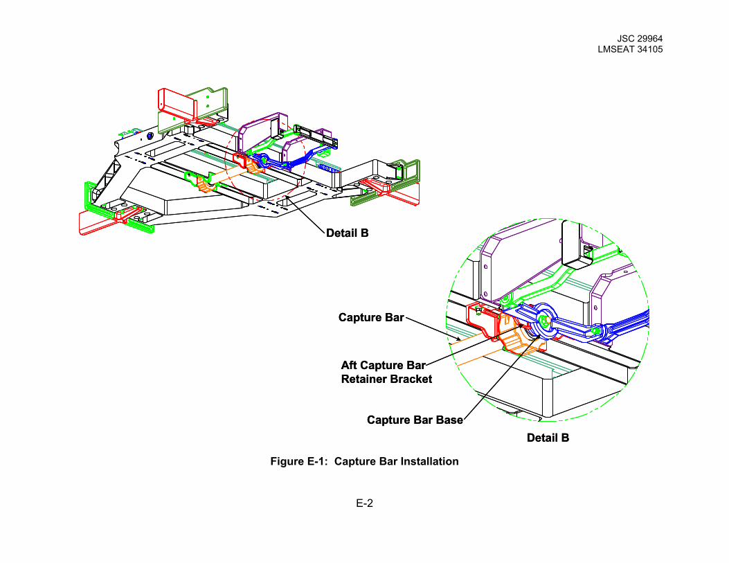
1. Prior to turning the Load Release Screws, the capture bar shall be fully
mated and supported by both bearing assemblies. The Capture Bar Base,
the end with the handle, shall have surface contact with the Aft Capture
Bar Retainer Bracket. See Figure E-1.
2. Insert a 7/16 internal hex drive into the EVA Extension Locking
Mechanism, P/N SEG39136828. The EVA Extension Locking Mechanism
is a part of the Load Release Screw 1 and 2. See Figure E-2. Depress
the locking mechanism retractor a minimum of .375 inches or until
bottomed out.
3. The Load Release Screws are turned in stages. Turn the Load Release
Screw with the 7/16 internal hex drive COUNTER CLOCKWISE. The
amount of turns for Load Release Screw 1 and 2 shall be the same. Turn
Load Release Screw 1 no more than 20 turns then alternate and turn Load
Release Screw 2 no more than 20 turns. Alternate back and forth
between the screws in increments not greater than 20 turns. Stop turning
the Load Release Screws when there is a significant rise in the
running/locking torque from both EVA nuts. Estimated number of turns for
each screw is 80 to 100 full revolutions. See Figure E-2
E-1
JSC 29964 LMSEAT 34105
Detail B
Detail B
Capture Bar
Aft Capture Bar Retainer Bracket
Capture Bar Base
Detail B
Detail B
Capture Bar
Aft Capture Bar Retainer Bracket
Capture Bar Base
Figure E-1: Capture Bar Installation
E-2

JSC 29964 LMSEAT 34105
Detail B
Locking MechanismRetractor
Load ReleaseScrew 2
Detail B
Load ReleaseScrew 1
Detail B
Locking MechanismRetractor
Load ReleaseScrew 2
Detail B
Load ReleaseScrew 1
Figure E-2: Load Release Screw
E-3

JSC 29964 LMSEAT 34105
Appendix F: AMS-02 Passive PAS Assembly Capture Bar Reset Procedure
DO NOT use POWER TOOLS for this procedure
Engage the EVA Release Mechanism screw using a 7/16 internal hex socket.
The EVA extension Locking Mechanism shall be depressed a minimum of .375.
Proper engagement shall deflect the locking mechanism to the solid or “bottomed
out” condition. Advance the EVA screw until the deflection gage reads zero. A
noticeable and sharp increase in torque should be expected.
Detail B
Locking MechanismRetractor
Load ReleaseScrew 2
Detail B
Load ReleaseScrew 1
Detail B
Locking MechanismRetractor
Load ReleaseScrew 2
Detail B
Load ReleaseScrew 1
Figure F-2: Load Release Screw
F-1