PARTS LIST FOR JCW-3504-0MHB/0MVB
12
1 ©Copyright 2000, Mi-T-M Corporation EX-9122-040700R0 Issue Date: 022399 HONDA ENGINE OIL GRADE: SAE 10W/30 HONDA ENGINE OIL CAPACITY: 37.1 oz. VANGUARD ENGINE OIL GRADE: Above 40°F=SAE30 Below 40°F=SAE10W-30 VANGUARD ENGINE OIL CAPACITY: 51 oz. PUMP OIL GRADE: Mi-T-M #AW-4085-0016 PUMP OIL CAPACITY: 16 oz. PRESSURE NOZZLE: 4.0 PARTS LIST FOR JCW-3504-0MHB/0MVB 8650 Enterprise Drive, Peosta IA 52068 319-556-7484 / Fax 319-556-1235
Transcript of PARTS LIST FOR JCW-3504-0MHB/0MVB

1©Copyright 2000, Mi-T-M Corporation EX-9122-040700R0Issue Date: 022399
HONDA ENGINE OIL GRADE: SAE 10W/30HONDA ENGINE OIL CAPACITY: 37.1 oz.VANGUARD ENGINE OIL GRADE: Above 40°F=SAE30
Below 40°F=SAE10W-30VANGUARD ENGINE OIL CAPACITY: 51 oz.PUMP OIL GRADE: Mi-T-M #AW-4085-0016PUMP OIL CAPACITY: 16 oz.PRESSURE NOZZLE: 4.0
PARTS LIST FOR
JCW-3504-0MHB/0MVB
8650 Enterprise Drive, Peosta IA 52068319-556-7484 / Fax 319-556-1235

2©Copyright 2000, Mi-T-M Corporation EX-9122-040700R0Issue Date: 022399
This Parts Listing has been compiled for your benefit. You can be assured your Mi-T-M pressure washer was constructed and designed with quality andperformance in mind using over 25 years experience in the pressure washer business. Each component has been rigorously tested to insure the highest levelof acceptance.
The contents of this Parts Listing are based on the latest product information available at the time of publication. Mi-T-M reserves the right to make changes inprice, color, materials, equipment, specifications or models at any time without notice.
WARNINGTHIS IS A PROFESSIONAL HIGH PRESSURE, PRESSURE WASHER. CAUTION SHOULD BE OBSERVED WHEN USINGOR REPAIRING THIS UNIT! READ AND FOLLOW THE SAFETY WARNINGS LISTED BELOW BEFORE ATTEMPTING ANY REPAIRS ONTHIS PRESSURE WASHER!
SAFETY WARNINGS1. NEVER alter or modify the equipment. Be sure any accessory items and system components being used will withstand the pressure developed. Use
only genuine Mi-T-M parts for repair of your pressure washer. Failure to do so can cause hazardous operating conditions and will VOID warranty.
2. NEVER make adjustments on machinery while the unit is connected to the engine without first removing the ignition cables from the spark plugs.Turning over the machinery by hand during adjustment or cleaning might start the engine and machinery with it, causing serious injury to the operator.
3. Know how to stop and bleed pressures quickly. Be thoroughly familiar with controls.
4. Before servicing the unit, turn unit off, relieve the water pressure and allow the unit to cool down. Do not make repairs while the unit is running.Service in a clean, dry, flat area. Block the wheels to prevent the unit from moving. Be especially careful to properly dispose of any flammablematerials.
5. After testing the machine, DO NOT leave the pressurized unit unattended. Shut off the unit and release trapped pressure before leaving.
Table of Contents
SPECIFICATIONS .........................................................................................................................................................................................................3FRAME ASSEMBLY .....................................................................................................................................................................................................4PUMP ASSEMBLY (3-0189) .........................................................................................................................................................................................6PUMP SERVICE GUIDE ...............................................................................................................................................................................................8GUN ASSEMBLY (16-0001) .........................................................................................................................................................................................10
3©Copyright 2000, Mi-T-M Corporation EX-9122-040700R0Issue Date: 022399
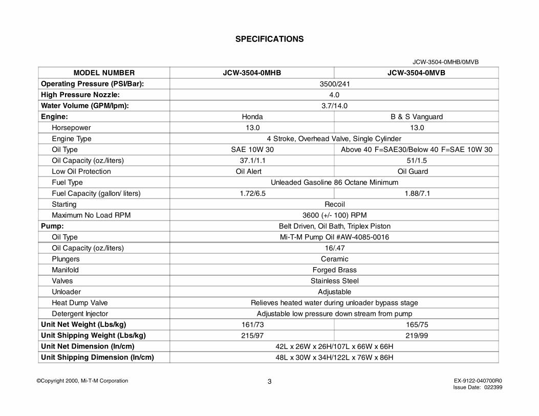
SPECIFICATIONS
JCW-3504-0MHB/0MVB
MODEL NUMBER JCW-3504-0MHB JCW-3504-0MVB
Operating Pressure (PSI/Bar): 3500/241
High Pressure Nozzle: 4.0
Water Volume (GPM/lpm): 3.7/14.0
Engine: Honda B & S Vanguard
Horsepower 13.0 13.0
Engine Type 4 Stroke, Overhead Valve, Single Cylinder
Oil Type SAE 10W 30 Above 40 F=SAE30/Below 40 F=SAE 10W 30
Oil Capacity (oz./liters) 37.1/1.1 51/1.5
Low Oil Protection Oil Alert Oil Guard
Fuel Type Unleaded Gasoline 86 Octane Minimum
Fuel Capacity (gallon/ liters) 1.72/6.5 1.88/7.1
Starting Recoil
Maximum No Load RPM 3600 (+/- 100) RPM
Pump: Belt Driven, Oil Bath, Triplex Piston
Oil Type Mi-T-M Pump Oil #AW-4085-0016
Oil Capacity (oz./liters) 16/.47
Plungers Ceramic
Manifold Forged Brass
Valves Stainless Steel
Unloader Adjustable
Heat Dump Valve Relieves heated water during unloader bypass stage
Detergent Injector Adjustable low pressure down stream from pump
Unit Net Weight (Lbs/kg) 161/73 165/75
Unit Shipping Weight (Lbs/kg) 215/97 219/99
Unit Net Dimension (In/cm) 42L x 26W x 26H/107L x 66W x 66H
Unit Shipping Dimension (In/cm) 48L x 30W x 34H/122L x 76W x 86H
4©Copyright 2000, Mi-T-M Corporation EX-9122-040700R0Issue Date: 022399
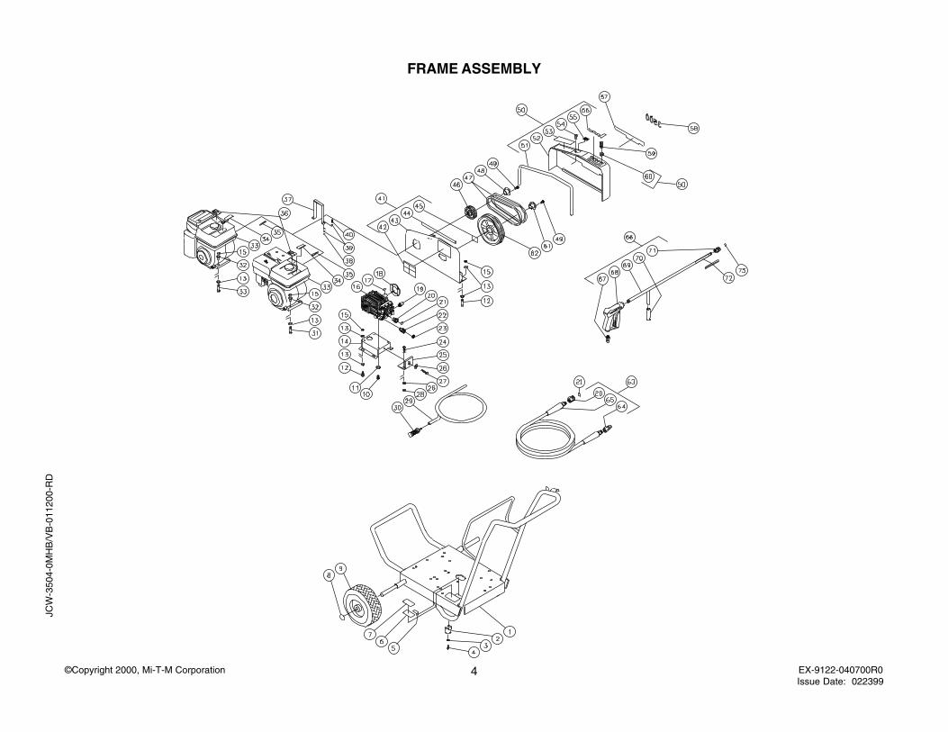
FRAME ASSEMBLY
JCW
-350
4-0M
HB
/VB
-011
200-
RD
5©Copyright 2000, Mi-T-M Corporation EX-9122-040700R0Issue Date: 022399
JCW-3504-0MHB/VB-011200-RD
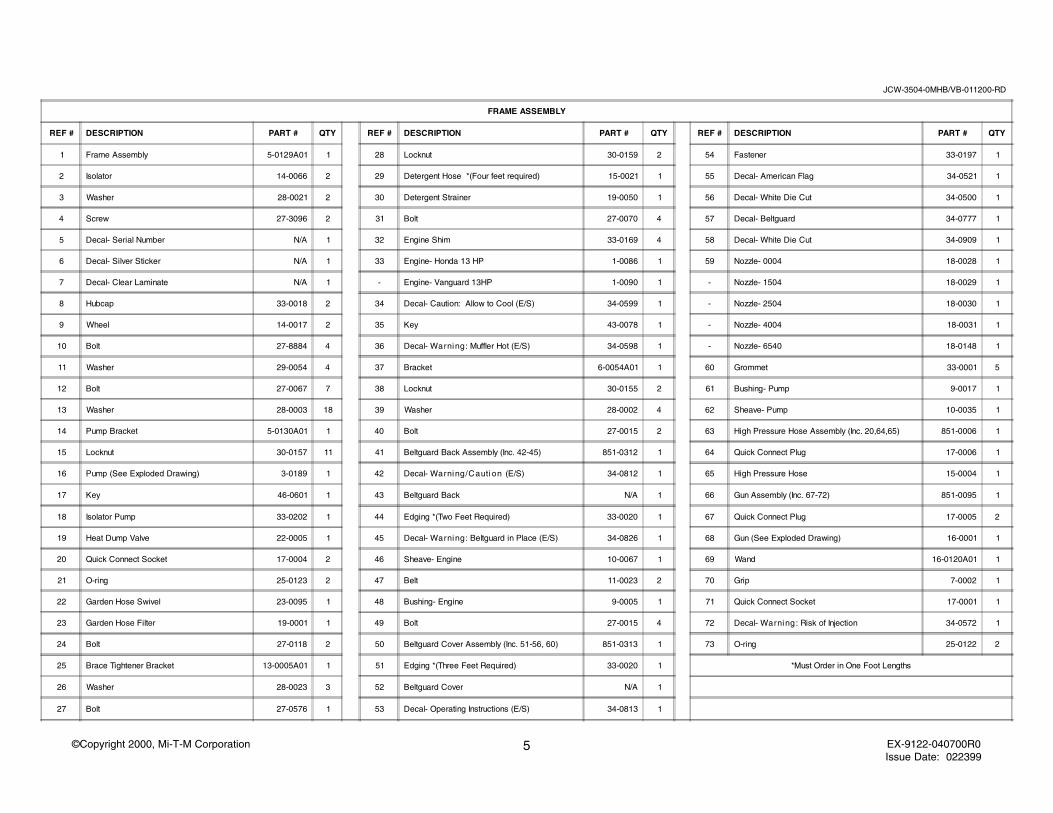
FRAME ASSEMBLY
REF # DESCRIPTION PART # QTY REF # DESCRIPTION PART # QTY REF # DESCRIPTION PART # QTY
1 Frame Assembly 5-0129A01 1 28 Locknut 30-0159 2 54 Fastener 33-0197 1
2 Isolator 14-0066 2 29 Detergent Hose *(Four feet required) 15-0021 1 55 Decal- American Flag 34-0521 1
3 Washer 28-0021 2 30 Detergent Strainer 19-0050 1 56 Decal- White Die Cut 34-0500 1
4 Screw 27-3096 2 31 Bolt 27-0070 4 57 Decal- Beltguard 34-0777 1
5 Decal- Serial Number N/A 1 32 Engine Shim 33-0169 4 58 Decal- White Die Cut 34-0909 1
6 Decal- Silver Sticker N/A 1 33 Engine- Honda 13 HP 1-0086 1 59 Nozzle- 0004 18-0028 1
7 Decal- Clear Laminate N/A 1 - Engine- Vanguard 13HP 1-0090 1 - Nozzle- 1504 18-0029 1
8 Hubcap 33-0018 2 34 Decal- Caution: Allow to Cool (E/S) 34-0599 1 - Nozzle- 2504 18-0030 1
9 Wheel 14-0017 2 35 Key 43-0078 1 - Nozzle- 4004 18-0031 1
10 Bolt 27-8884 4 36 Decal- Warning: Muffler Hot (E/S) 34-0598 1 - Nozzle- 6540 18-0148 1
11 Washer 29-0054 4 37 Bracket 6-0054A01 1 60 Grommet 33-0001 5
12 Bolt 27-0067 7 38 Locknut 30-0155 2 61 Bushing- Pump 9-0017 1
13 Washer 28-0003 18 39 Washer 28-0002 4 62 Sheave- Pump 10-0035 1
14 Pump Bracket 5-0130A01 1 40 Bolt 27-0015 2 63 High Pressure Hose Assembly (Inc. 20,64,65) 851-0006 1
15 Locknut 30-0157 11 41 Beltguard Back Assembly (Inc. 42-45) 851-0312 1 64 Quick Connect Plug 17-0006 1
16 Pump (See Exploded Drawing) 3-0189 1 42 Decal- Warning/Cauti on (E/S) 34-0812 1 65 High Pressure Hose 15-0004 1
17 Key 46-0601 1 43 Beltguard Back N/A 1 66 Gun Assembly (Inc. 67-72) 851-0095 1
18 Isolator Pump 33-0202 1 44 Edging *(Two Feet Required) 33-0020 1 67 Quick Connect Plug 17-0005 2
19 Heat Dump Valve 22-0005 1 45 Decal- Warning: Beltguard in Place (E/S) 34-0826 1 68 Gun (See Exploded Drawing) 16-0001 1
20 Quick Connect Socket 17-0004 2 46 Sheave- Engine 10-0067 1 69 Wand 16-0120A01 1
21 O-ring 25-0123 2 47 Belt 11-0023 2 70 Grip 7-0002 1
22 Garden Hose Swivel 23-0095 1 48 Bushing- Engine 9-0005 1 71 Quick Connect Socket 17-0001 1
23 Garden Hose Filter 19-0001 1 49 Bolt 27-0015 4 72 Decal- Warning: Risk of Injection 34-0572 1
24 Bolt 27-0118 2 50 Beltguard Cover Assembly (Inc. 51-56, 60) 851-0313 1 73 O-ring 25-0122 2
25 Brace Tightener Bracket 13-0005A01 1 51 Edging *(Three Feet Required) 33-0020 1 *Must Order in One Foot Lengths
26 Washer 28-0023 3 52 Beltguard Cover N/A 1
27 Bolt 27-0576 1 53 Decal- Operating Instructions (E/S) 34-0813 1
6©Copyright 2000, Mi-T-M Corporation EX-9122-040700R0Issue Date: 022399
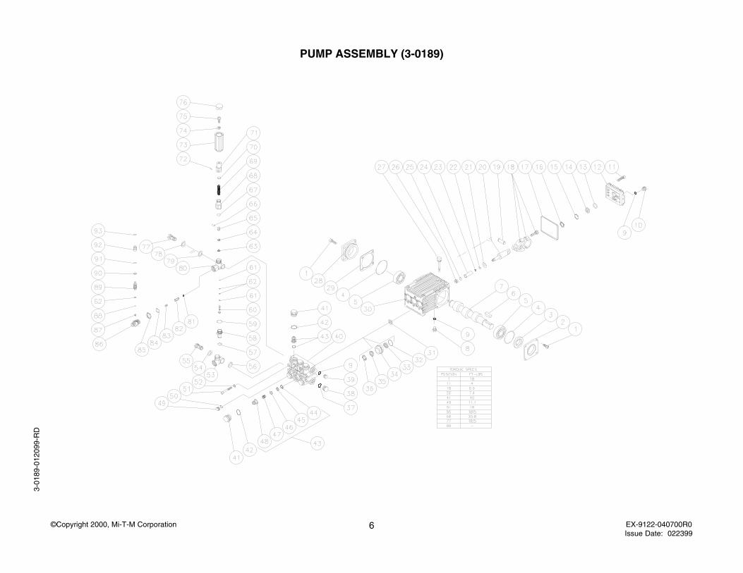
PUMP ASSEMBLY (3-0189)
3-01
89-0
1209
9-R
D
7©Copyright 2000, Mi-T-M Corporation EX-9122-040700R0Issue Date: 022399
3-0189-012099-RD
PUMP ASSEMBLY (3-0189)
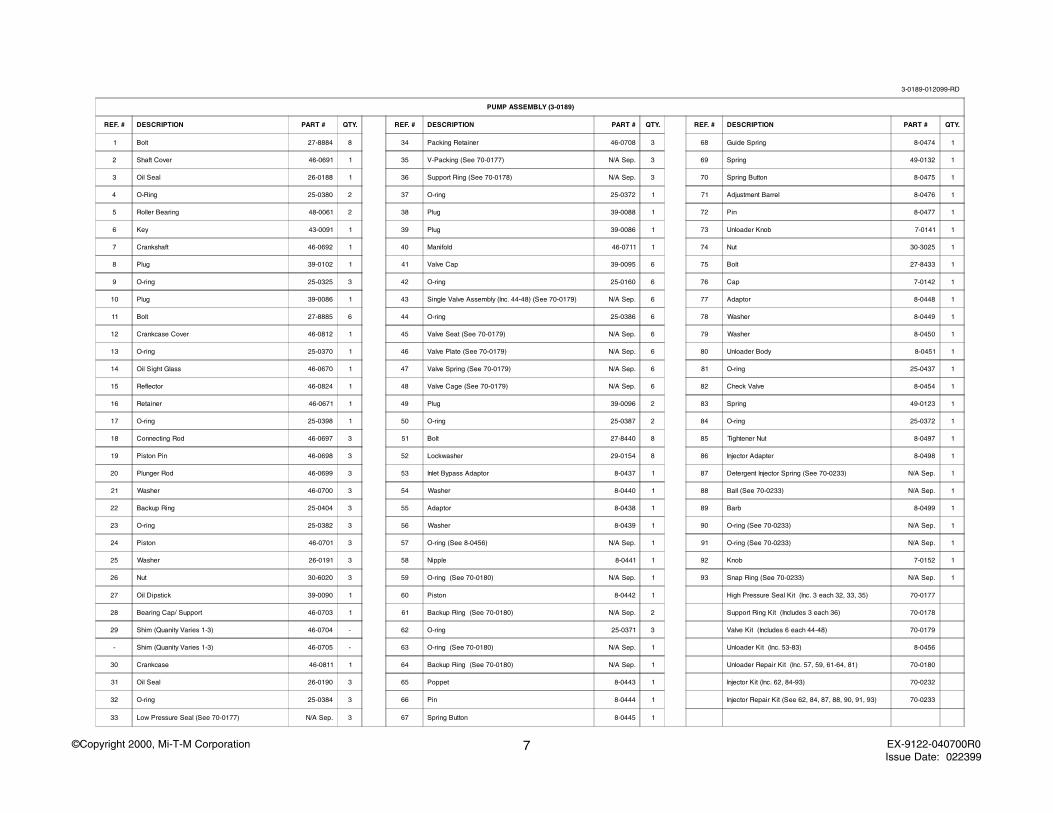
REF. # DESCRIPTION PART # QTY. REF. # DESCRIPTION PART # QTY. REF. # DESCRIPTION PART # QTY.
1 Bolt 27-8884 8 34 Packing Retainer 46-0708 3 68 Guide Spring 8-0474 1
2 Shaft Cover 46-0691 1 35 V-Packing (See 70-0177) N/A Sep. 3 69 Spring 49-0132 1
3 Oil Seal 26-0188 1 36 Support Ring (See 70-0178) N/A Sep. 3 70 Spring Button 8-0475 1
4 O-Ring 25-0380 2 37 O-ring 25-0372 1 71 Adjustment Barrel 8-0476 1
5 Roller Bearing 48-0061 2 38 Plug 39-0088 1 72 Pin 8-0477 1
6 Key 43-0091 1 39 Plug 39-0086 1 73 Unloader Knob 7-0141 1
7 Crankshaft 46-0692 1 40 Manifold 46-0711 1 74 Nut 30-3025 1
8 Plug 39-0102 1 41 Valve Cap 39-0095 6 75 Bolt 27-8433 1
9 O-ring 25-0325 3 42 O-ring 25-0160 6 76 Cap 7-0142 1
10 Plug 39-0086 1 43 Single Valve Assembly (Inc. 44-48) (See 70-0179) N/A Sep. 6 77 Adaptor 8-0448 1
11 Bolt 27-8885 6 44 O-ring 25-0386 6 78 Washer 8-0449 1
12 Crankcase Cover 46-0812 1 45 Valve Seat (See 70-0179) N/A Sep. 6 79 Washer 8-0450 1
13 O-ring 25-0370 1 46 Valve Plate (See 70-0179) N/A Sep. 6 80 Unloader Body 8-0451 1
14 Oil Sight Glass 46-0670 1 47 Valve Spring (See 70-0179) N/A Sep. 6 81 O-ring 25-0437 1
15 Reflector 46-0824 1 48 Valve Cage (See 70-0179) N/A Sep. 6 82 Check Valve 8-0454 1
16 Retainer 46-0671 1 49 Plug 39-0096 2 83 Spring 49-0123 1
17 O-ring 25-0398 1 50 O-ring 25-0387 2 84 O-ring 25-0372 1
18 Connecting Rod 46-0697 3 51 Bolt 27-8440 8 85 Tightener Nut 8-0497 1
19 Piston Pin 46-0698 3 52 Lockwasher 29-0154 8 86 Injector Adapter 8-0498 1
20 Plunger Rod 46-0699 3 53 Inlet Bypass Adaptor 8-0437 1 87 Detergent Injector Spring (See 70-0233) N/A Sep. 1
21 Washer 46-0700 3 54 Washer 8-0440 1 88 Ball (See 70-0233) N/A Sep. 1
22 Backup Ring 25-0404 3 55 Adaptor 8-0438 1 89 Barb 8-0499 1
23 O-ring 25-0382 3 56 Washer 8-0439 1 90 O-ring (See 70-0233) N/A Sep. 1
24 Piston 46-0701 3 57 O-ring (See 8-0456) N/A Sep. 1 91 O-ring (See 70-0233) N/A Sep. 1
25 Washer 26-0191 3 58 Nipple 8-0441 1 92 Knob 7-0152 1
26 Nut 30-6020 3 59 O-ring (See 70-0180) N/A Sep. 1 93 Snap Ring (See 70-0233) N/A Sep. 1
27 Oil Dipstick 39-0090 1 60 Piston 8-0442 1 High Pressure Seal Kit (Inc. 3 each 32, 33, 35) 70-0177
28 Bearing Cap/ Support 46-0703 1 61 Backup Ring (See 70-0180) N/A Sep. 2 Support Ring Kit (Includes 3 each 36) 70-0178
29 Shim (Quanity Varies 1-3) 46-0704 - 62 O-ring 25-0371 3 Valve Kit (Includes 6 each 44-48) 70-0179
- Shim (Quanity Varies 1-3) 46-0705 - 63 O-ring (See 70-0180) N/A Sep. 1 Unloader Kit (Inc. 53-83) 8-0456
30 Crankcase 46-0811 1 64 Backup Ring (See 70-0180) N/A Sep. 1 Unloader Repair Kit (Inc. 57, 59, 61-64, 81) 70-0180
31 Oil Seal 26-0190 3 65 Poppet 8-0443 1 Injector Kit (Inc. 62, 84-93) 70-0232
32 O-ring 25-0384 3 66 Pin 8-0444 1 Injector Repair Kit (See 62, 84, 87, 88, 90, 91, 93) 70-0233
33 Low Pressure Seal (See 70-0177) N/A Sep. 3 67 Spring Button 8-0445 1
8©Copyright 2000, Mi-T-M Corporation EX-9122-040700R0Issue Date: 022399
PUMP SERVICE GUIDE
USE THE PARTS LIST ON THE PREVIOUS PAGE TO REORDER PARTS NEEDED TO SERVICE YOUR PUMP.
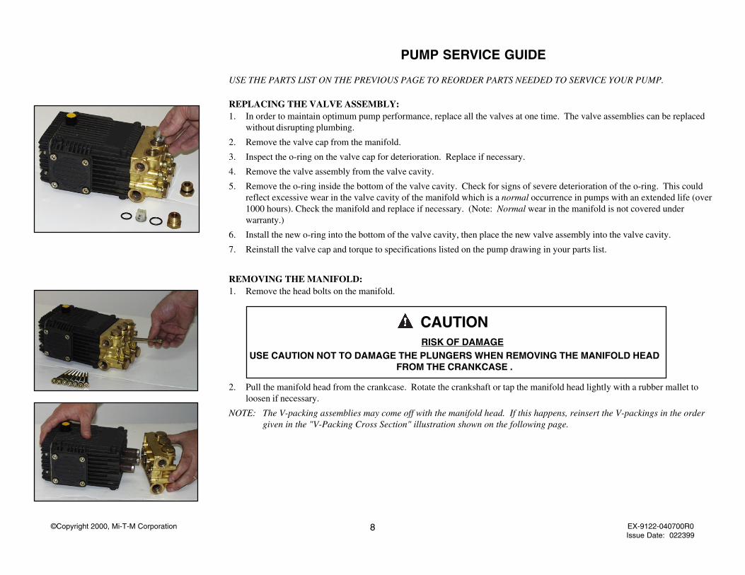
REPLACING THE VALVE ASSEMBLY:1. In order to maintain optimum pump performance, replace all the valves at one time. The valve assemblies can be replaced
without disrupting plumbing.
2. Remove the valve cap from the manifold.
3. Inspect the o-ring on the valve cap for deterioration. Replace if necessary.
4. Remove the valve assembly from the valve cavity.
5. Remove the o-ring inside the bottom of the valve cavity. Check for signs of severe deterioration of the o-ring. This couldreflect excessive wear in the valve cavity of the manifold which is a normal occurrence in pumps with an extended life (over1000 hours). Check the manifold and replace if necessary. (Note: Normal wear in the manifold is not covered underwarranty.)
6. Install the new o-ring into the bottom of the valve cavity, then place the new valve assembly into the valve cavity.
7. Reinstall the valve cap and torque to specifications listed on the pump drawing in your parts list.
REMOVING THE MANIFOLD:1. Remove the head bolts on the manifold.
2. Pull the manifold head from the crankcase. Rotate the crankshaft or tap the manifold head lightly with a rubber mallet toloosen if necessary.
NOTE: The V-packing assemblies may come off with the manifold head. If this happens, reinsert the V-packings in the ordergiven in the "V-Packing Cross Section" illustration shown on the following page.
CAUTION RISK OF DAMAGE
USE CAUTION NOT TO DAMAGE THE PLUNGERS WHEN REMOVING THE MANIFOLD HEADFROM THE CRANKCASE .
9©Copyright 2000, Mi-T-M Corporation EX-9122-040700R0Issue Date: 022399
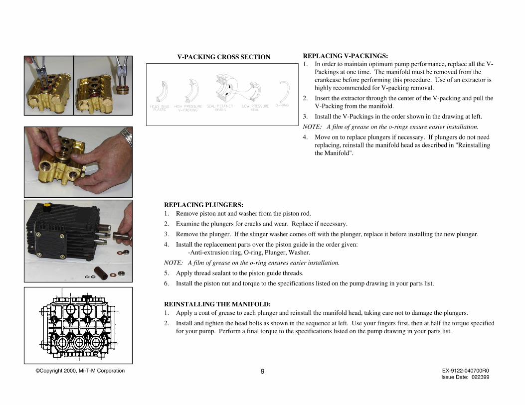
REPLACING PLUNGERS:1. Remove piston nut and washer from the piston rod.
2. Examine the plungers for cracks and wear. Replace if necessary.
3. Remove the plunger. If the slinger washer comes off with the plunger, replace it before installing the new plunger.
4. Install the replacement parts over the piston guide in the order given:-Anti-extrusion ring, O-ring, Plunger, Washer.
NOTE: A film of grease on the o-ring ensures easier installation.
5. Apply thread sealant to the piston guide threads.
6. Install the piston nut and torque to the specifications listed on the pump drawing in your parts list.
REINSTALLING THE MANIFOLD:1. Apply a coat of grease to each plunger and reinstall the manifold head, taking care not to damage the plungers.
2. Install and tighten the head bolts as shown in the sequence at left. Use your fingers first, then at half the torque specifiedfor your pump. Perform a final torque to the specifications listed on the pump drawing in your parts list.
V-PACKING CROSS SECTION REPLACING V-PACKINGS:1. In order to maintain optimum pump performance, replace all the V-
Packings at one time. The manifold must be removed from thecrankcase before performing this procedure. Use of an extractor ishighly recommended for V-packing removal.
2. Insert the extractor through the center of the V-packing and pull theV-Packing from the manifold.
3. Install the V-Packings in the order shown in the drawing at left.
NOTE: A film of grease on the o-rings ensure easier installation.
4. Move on to replace plungers if necessary. If plungers do not needreplacing, reinstall the manifold head as described in "Reinstallingthe Manifold".
10©Copyright 2000, Mi-T-M Corporation EX-9122-040700R0Issue Date: 022399
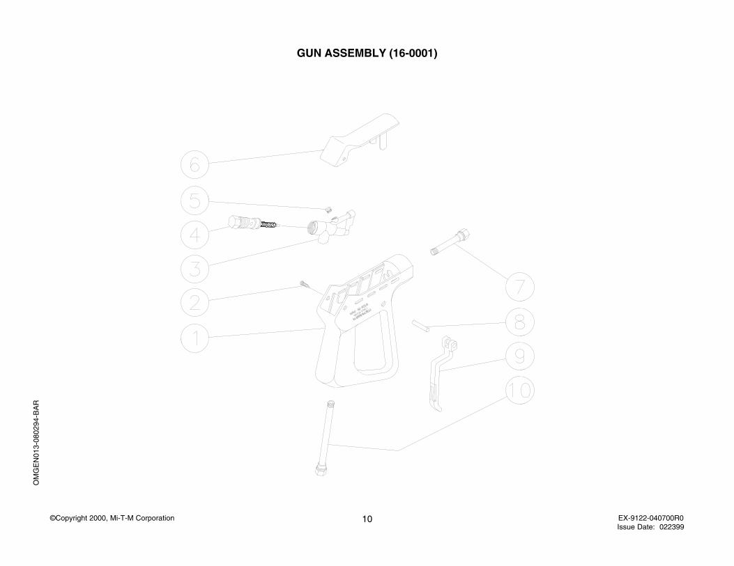
GUN ASSEMBLY (16-0001)
OM
GE
N01
3-08
0294
-BA
R
11©Copyright 2000, Mi-T-M Corporation EX-9122-040700R0Issue Date: 022399
OMGEN013-080294-BAR
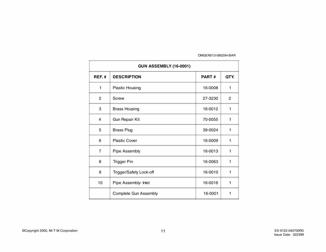
GUN ASSEMBLY (16-0001)
REF. # DESCRIPTION PART # QTY.
1 Plastic Housing 16-0008 1
2 Screw 27-3230 2
3 Brass Housing 16-0012 1
4 Gun Repair Kit 70-0055 1
5 Brass Plug 39-0024 1
6 Plastic Cover 16-0009 1
7 Pipe Assembly 16-0013 1
8 Trigger Pin 16-0063 1
9 Trigger/Safety Lock-off 16-0010 1
10 Pipe Assembly- Inlet 16-0016 1
Complete Gun Assembly 16-0001 1
12©Copyright 2000, Mi-T-M Corporation EX-9122-040700R0Issue Date: 022399