
Parts bearings gearing
52
-
Upload
rebel-munna -
Category
Documents
-
view
1.803 -
download
0
Transcript of Parts bearings gearing

Engine Parts, Description, Function, Construction
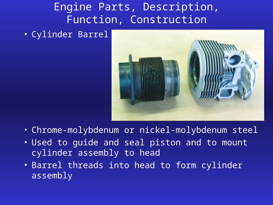
• Cylinder Barrel
• Chrome-molybdenum or nickel-molybdenum steel• Used to guide and seal piston and to mount cylinder
assembly to head• Barrel threads into head to form cylinder assembly

Engine Parts, Description, Function, Construction
Cylinder interior wall
Cylinder Walls

Engine Parts, Description, Function, Construction
• Cylinder Walls• Inside surface of cylinder barrel is honed to a
controlled amount of roughness• Rough enough to hold oil film but smooth enough to
minimize friction and wear• Plain steel cylinder walls are not treated to prevent
wear or corrosion• Nitrided cylinder walls are hardened to reduce wear
but still rust as easily as plain steel walls. Nitriding is exposing the cylinder wall to ammonia at high temperatures and it hardens the wall to a thickness of approximately .005”

Engine Parts, Description, Function, Construction
• Chrome cylinder walls use chromium plating to resist wear and provide a corrosion resistant surface.
• Cylinders may be chromed back to standard inside dimensions if they become worn
• Chrome is too smooth to hold oil without etching or channeling during the overhaul process
Engine Parts, Description, Function, Construction
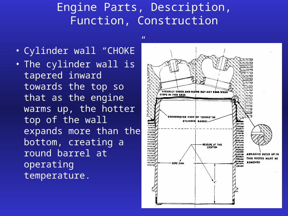
• Cylinder wall “CHOKE”• The cylinder wall is
tapered inward towards the top so that as the engine warms up, the hotter top of the wall expands more than the bottom, creating a round barrel at operating temperature.
Engine Parts, Description, Function, Construction
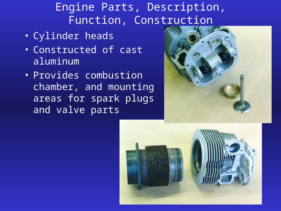
• Cylinder heads• Constructed of cast
aluminum• Provides combustion
chamber, and mounting areas for spark plugs and valve parts

Engine Parts, Description, Function, Construction
• The cylinder head is designed to transfer heat by conduction to the fins and then from the fins to the air by convection
• The exhaust side of the head has the most fins as it runs the hottest
• The head also may incorporate a drain line fitting to allow excess oil to return to the crankcase
(intercylinder drain lines on radials)
Engine Parts, Description, Function, Construction
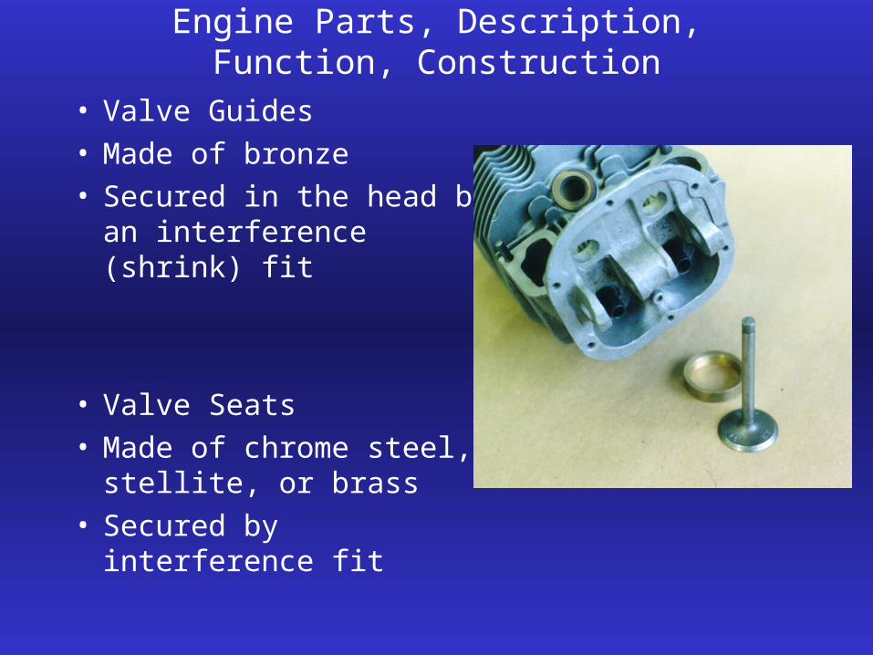
• Valve Guides• Made of bronze• Secured in the head by an
interference (shrink) fit
• Valve Seats• Made of chrome steel,
stellite, or brass• Secured by interference fit

• Crankcase• The crankcase holds all of the engine parts in
alignment and supports the cylinders and crankshaft
• It provides a place to mount the engine to the aircraft
• Constructed of aluminum alloy• Divided into sections (radial)
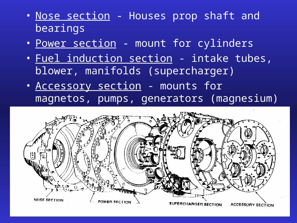
• Nose section - Houses prop shaft and bearings• Power section - mount for cylinders• Fuel induction section - intake tubes, blower,
manifolds (supercharger)• Accessory section - mounts for magnetos, pumps,
generators (magnesium)

• Opposed crankcase• Sections are not as distinct as in the radial and the
crankcase splits from front to rear instead of in radial sections

• Pistons• Constructed of aluminum alloy• Parts include top, ring grooves, ring lands, skirt, and piston pin boss• Cooling fins on the bottom help the oil carry heat away from the
piston top
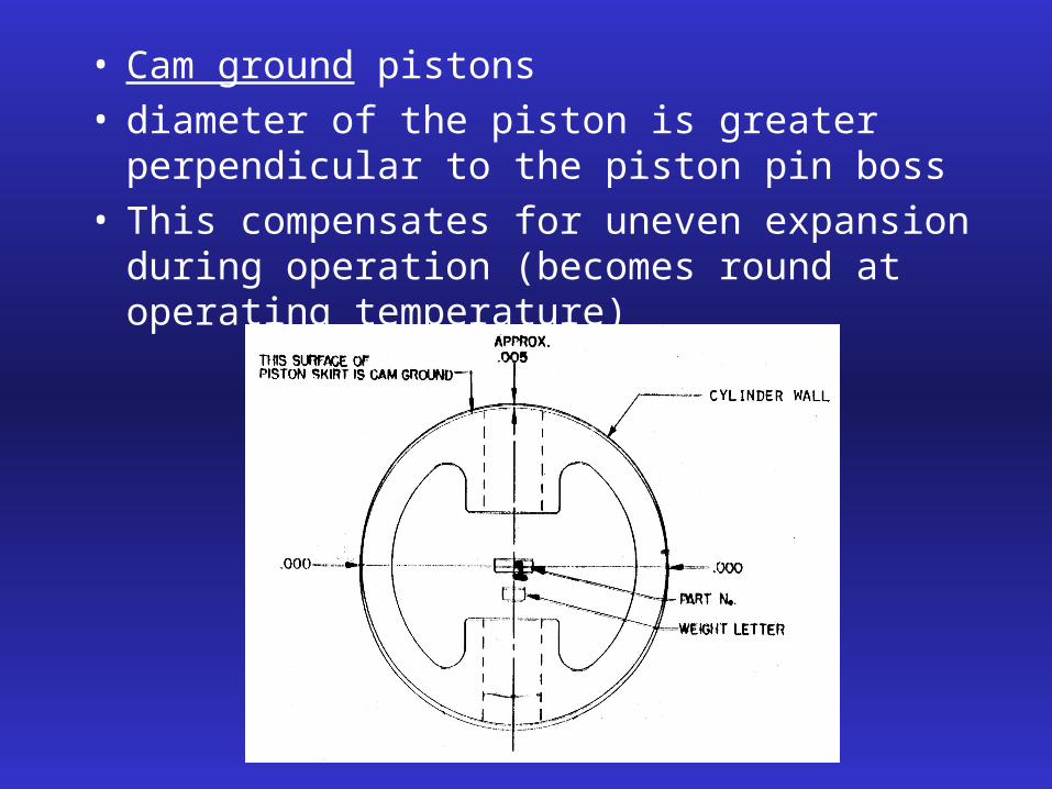
• Cam ground pistons• diameter of the piston is greater perpendicular to
the piston pin boss• This compensates for uneven expansion during
operation (becomes round at operating temperature)

• Piston head designs
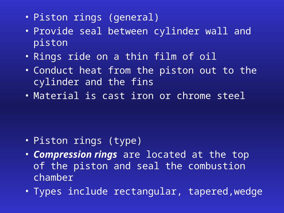
• Piston rings (general)• Provide seal between cylinder wall and piston• Rings ride on a thin film of oil• Conduct heat from the piston out to the cylinder
and the fins• Material is cast iron or chrome steel
• Piston rings (type)• Compression rings are located at the top of the
piston and seal the combustion chamber• Types include rectangular, tapered,wedge

• Compression rings

• Oil control rings• On bottom of piston below compression rings • Regulates oil film thickness on cylinder wall• Holes in ring and piston allow excess oil to drain
back to crankcase• Too much oil film and the engine will use
excessive oil and too little oil causes heat and insufficient lubrication
• Oil scraper rings• Directs the oil away from or towards the oil control
rings depending upon the requirements of the engine

• Piston ring end gap• The gap at the end of the rings allows for expansion
and contraction and unevenness in the cylinder wall• Butt, step and angle types • Always stagger the end gaps during ring
installation to prevent losing compression
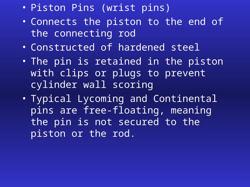
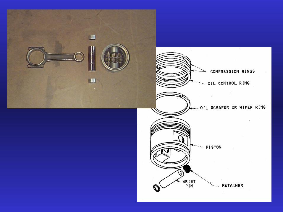
• Piston Pins (wrist pins)• Connects the piston to the end of the connecting
rod• Constructed of hardened steel• The pin is retained in the piston with clips or plugs
to prevent cylinder wall scoring• Typical Lycoming and Continental pins are free-
floating, meaning the pin is not secured to the piston or the rod.

• Connecting Rod Assembly
• The link between the crankshaft and the piston• Normally steel but some low powered engines use aluminum to
save weight• Cross section is an “H” or “I”• Types include : Plain Rod Fork and blade
rod Master and articulated

• Plain Type Rods
• Used on inline and opposed engines• Small bushing at piston pin end is pressed in place
and reamed to final dimensions• Large end of rod includes a cap, bolts, nuts, and
plain bearing inserts• Rods are numbered as to cylinder and for cap-to-
rod alignment

• Fork and Blade Connecting Rod
• Used on “V” type engines• One rod inside another allows cylinders to be
aligned and to share a common location on the crankshaft
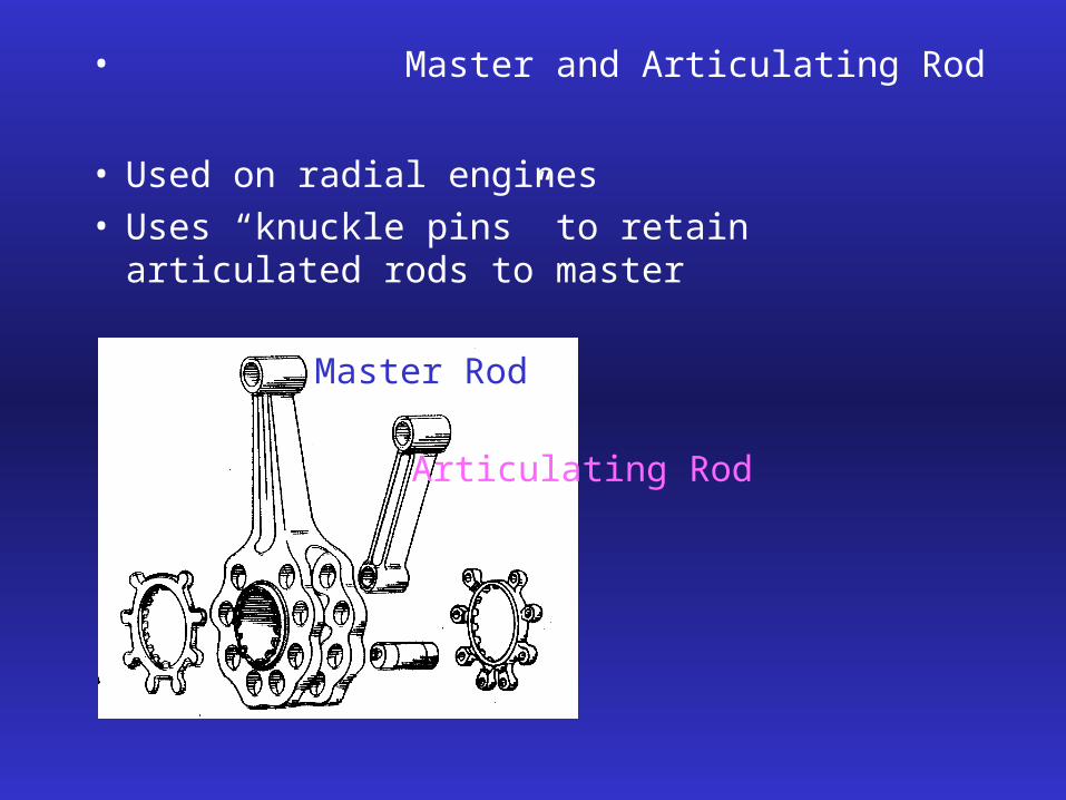
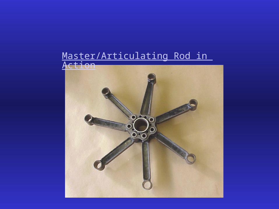
• Master and Articulating Rod
• Used on radial engines• Uses “knuckle pins” to retain articulated rods to
master
Master Rod
Articulating Rod

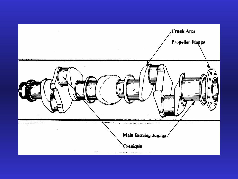
• Crankshaft
• Changes reciprocating motion of pistons into rotating motion to drive propeller
• Constructed of chrome-nickel-molybdenum-steel• May be one piece or as many as three separate
pieces• The propeller mounts to the front of the crankshaft
using a spline, taper, or flange• The crankshaft rotates within the crankcase and is
supported by main bearing journals• Crankshaft throws or crankpins are off center and
account for the reciprocating motion of the pistons

Crankshaft Main Bearing Journal, Pin, Arm
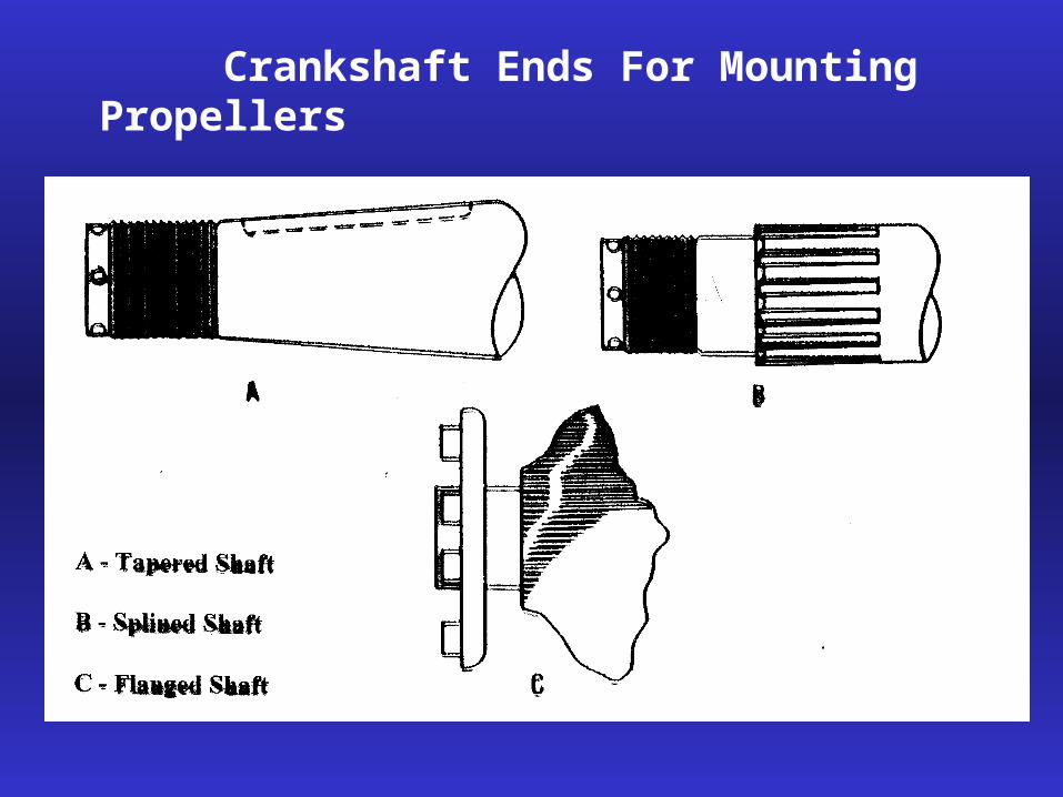
Crankshaft Ends For Mounting Propellers

• Dynamic Dampers can be mounted to the crankshaft to reduce vibration (floating)
• Counterweights are also used to reduce vibration but they are rigid and do not float
• Counterweights and dampers are used in piston engines because the power pulses and movement of the pistons create large amounts of vibration
• Vibration shortens airframe and engine life and can lead to premature component failure
• The engine is also mounted in rubber bushings to absorb vibration

• 2 Piece Crankshaft With Counterweights (Single Throw, Single Cylinder)

• Valves and the Valve System• Valves control the flow of gases inside the engine• Poppet valves are the most common and get their
name from the popping open and closed during operation
• Intake valves are chrome steel and are cooled by the incoming air and fuel mixture
• Exhaust valves are also alloy steel but are often filled with metallic sodium for cooling. Valve faces may be coated with Stellite to reduce wear and corrosion
• Valve faces are ground to 30 degrees for intake (airflow) and 45 degrees (cooling) for exhaust


1290 degrees F (typical)
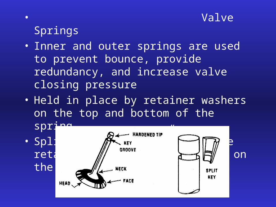
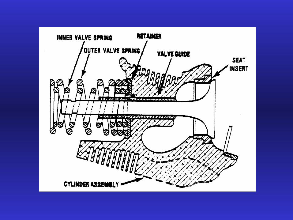
• Valve Springs• Inner and outer springs are used to prevent bounce,
provide redundancy, and increase valve closing pressure
• Held in place by retainer washers on the top and bottom of the spring
• Split key or “keeper” holds the retainers and springs in place on the valve stem
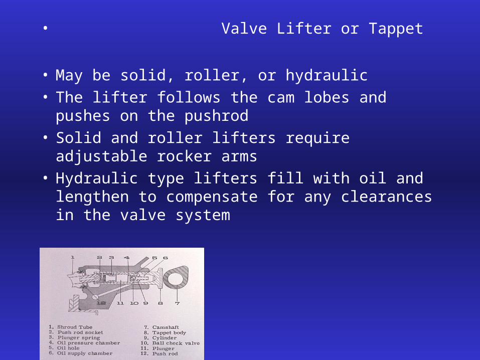
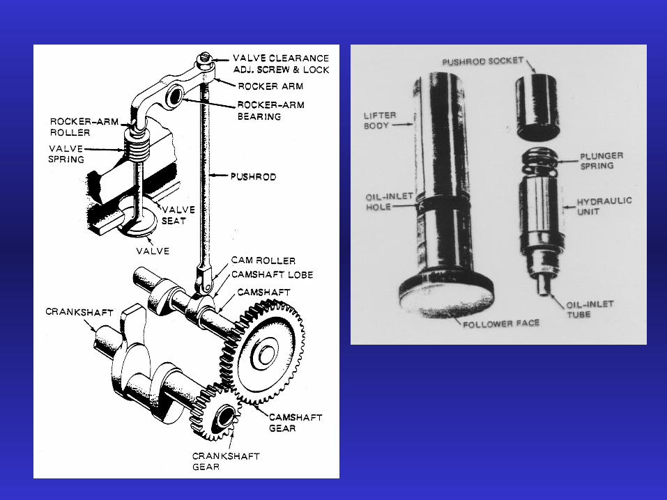
• Valve Lifter or Tappet
• May be solid, roller, or hydraulic• The lifter follows the cam lobes and pushes on the
pushrod• Solid and roller lifters require adjustable rocker arms• Hydraulic type lifters fill with oil and lengthen to
compensate for any clearances in the valve system
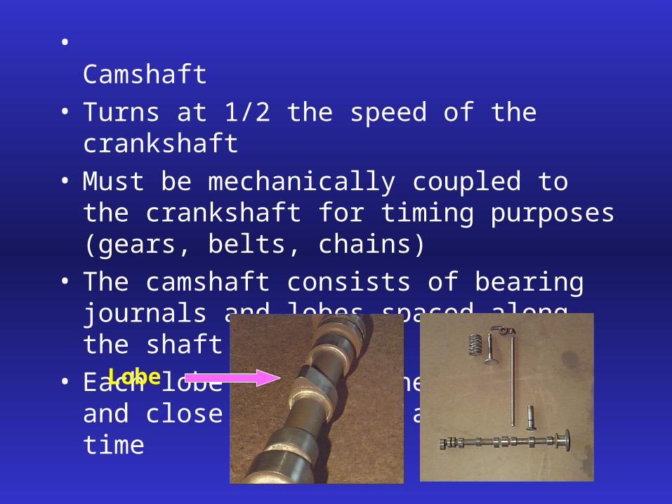
• Camshaft• Turns at 1/2 the speed of the crankshaft• Must be mechanically coupled to the crankshaft for
timing purposes (gears, belts, chains)• The camshaft consists of bearing journals and lobes
spaced along the shaft• Each lobe is positioned to open and close a valve at
a specific time
Lobe

• Pushrod• transmits push of lifter up to rocker arm• Hollow to allow oil to flow to the top of the
cylinder for valve part lubrication• Length can be varied to adjust valve clearance• Valve clearance is the space between the top of the
valve stem and the rocker arm. This clearance is to prevent a valve from being held open with the resulting heat build-up and loss of compression
• valve clearance increases as the engine operates due to cylinder expansion (solid lifters)
• Hydraulic lifters have a “0” clearance in operation

Valve clearance adjustment
Valve clearance measurement

• Rocker Arm• Adjustable in solid lifter engines and fixed in
engines with hydraulic lifters• One end rests on the valve stem and the other on
the pushrod• Rocking motion opens and closes the valves• Roller rocker arms incorporate a roller that reduces
friction and are used in some radials and experimental engines
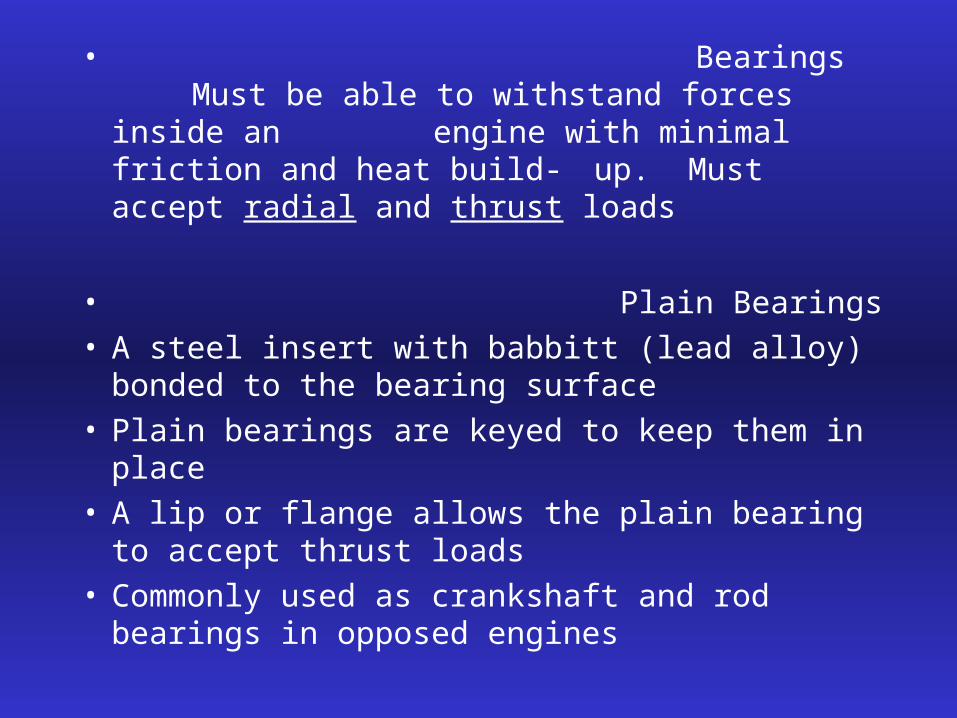
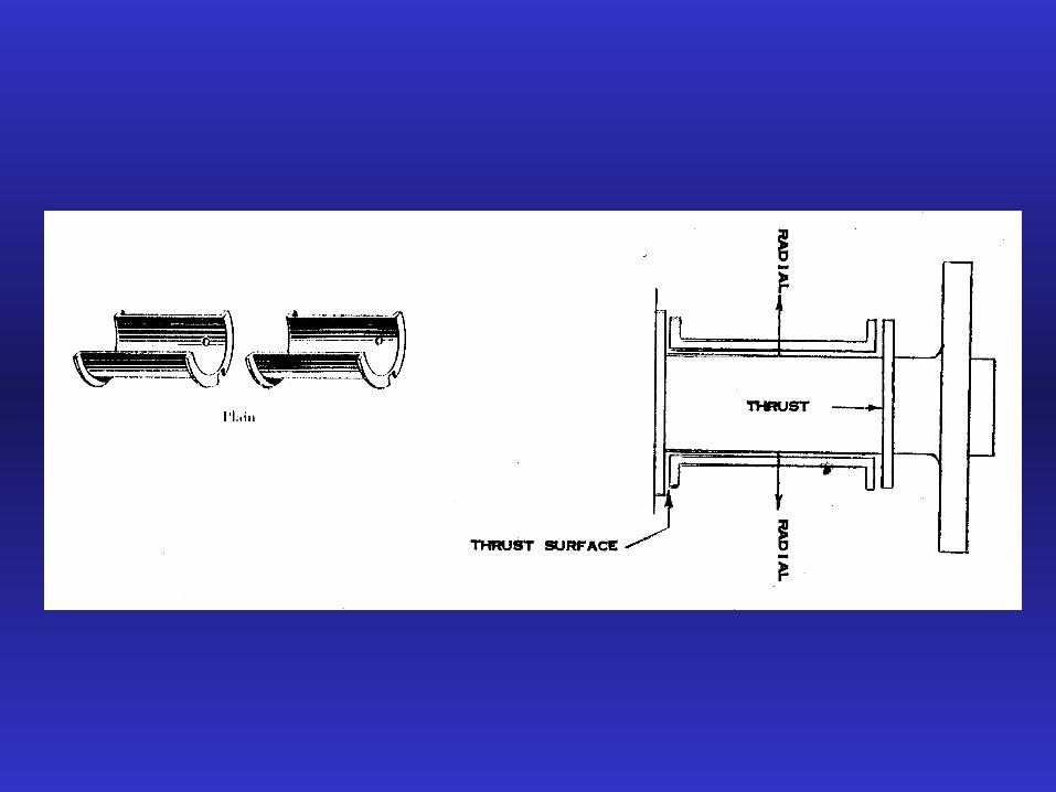
• BearingsMust be able to withstand forces inside an engine with minimal friction and heat build- up. Must accept radial and thrust loads
• Plain Bearings• A steel insert with babbitt (lead alloy) bonded to
the bearing surface• Plain bearings are keyed to keep them in place • A lip or flange allows the plain bearing to accept
thrust loads• Commonly used as crankshaft and rod bearings in
opposed engines
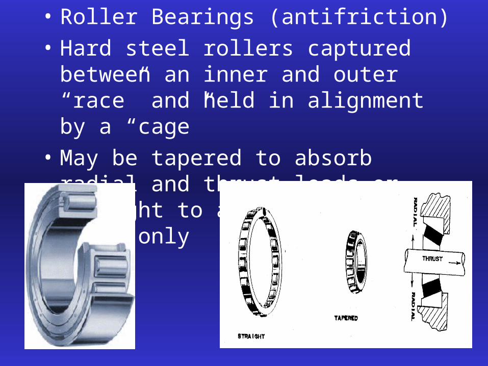
• Roller Bearings (antifriction)
• Hard steel rollers captured between an inner and outer “race” and held in alignment by a “cage”
• May be tapered to absorb radial and thrust loads or straight to absorb radial loads only
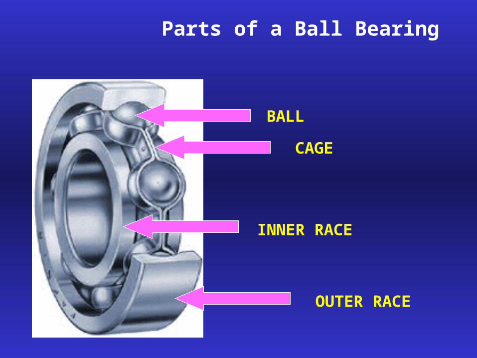
Parts of a Ball Bearing
OUTER RACE
INNER RACE
CAGE
BALL

• Ball Bearings (antifriction)
• Used for both radial and thrust loads
• Deep grooves in races allow thrust loads

Bearing cleaning and safety
• Wash old grease and debris with solvent• Blow dry with shop air but do not spin the bearing
with the air blast• Reapply grease or oil immediately to prevent
corrosion• Protect skin and eyes from solvent contact

Propeller Reduction Gearing
• Purpose is to reduce propeller rpm to its optimal speed and to increase engine rpm to its optimal speed
• Propeller always turns slower than the engine
• Gear Ratios:• Expressed as 2:1, .64:1, 300:1• At what speed will the propeller be turning if the
engine rpm is 2000 and the gear ratio is 2:1?• 1000 rpm
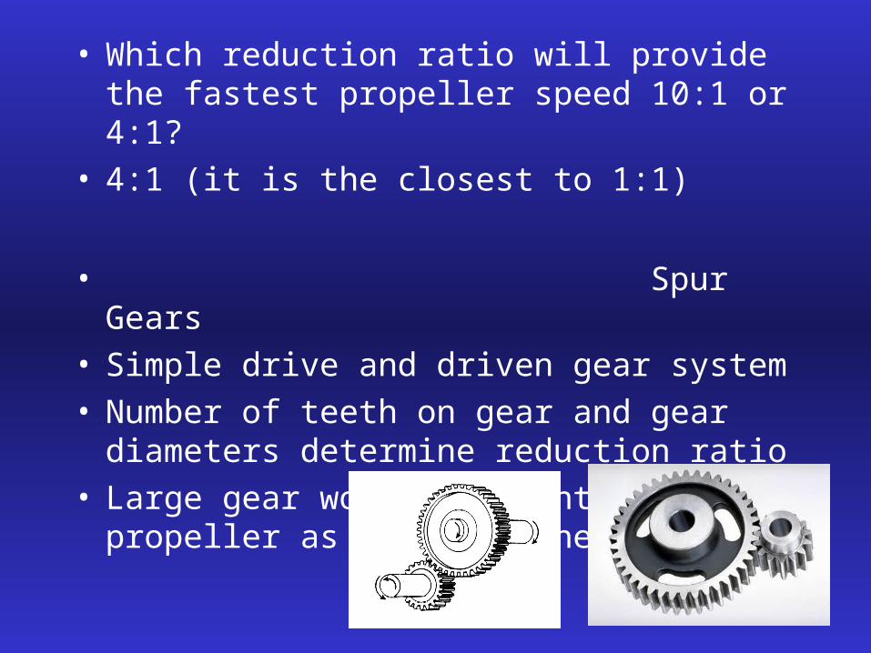
• Which reduction ratio will provide the fastest propeller speed 10:1 or 4:1?
• 4:1 (it is the closest to 1:1)
• Spur Gears• Simple drive and driven gear system• Number of teeth on gear and gear diameters
determine reduction ratio• Large gear would be mounted to propeller as it
turns the slowest

• Planetary Gears
• Ring gear, Planet gear, Sun gear• Large gear reductions possible• Compact and versatile• Common in large radials and turbine engines


![[47] Strain wave gearing design system wave gearing...167 AMTEC [47] Strain wave gearing design system Fig.47.1 Strain wave gearing design system 47.1 Overview Strain wave gearing](https://static.fdocuments.us/doc/165x107/5e356487029e073cbd586fdc/47-strain-wave-gearing-design-wave-gearing-167-amtec-47-strain-wave-gearing.jpg)