
PARTS & OPERATION MANUAL MODEL MT-300 / MT600
23
PARTS & OPERATION MANUAL MODEL MT-300 / MT600 MT300 803-M-T3-GP-Y—2803 to Current MT600 816-M-T6-GK-Y-*02816 to Current SOLD & SERVICED BY
Transcript of PARTS & OPERATION MANUAL MODEL MT-300 / MT600

PARTS & OPERATION MANUAL
MODEL MT-300 / MT600
MT300 803-M-T3-GP-Y—2803 to Current
MT600 816-M-T6-GK-Y-*02816 to Current
SOLD & SERVICED BY

Calder BrothModel: MT-
13
1. Hose R2. Asphal3. Motor, 4. Hydrau
Cou5. Asphal6. Asphal7. Valve 3
3 Wa8. Valve 29. Valve, 10. Hands
Nozz Vav
11. Spray Nozz Valv
12. Load Cap
13. Tank, Tank
hers Corporatio300 & MT-600
3
Reel...........t Hose (ReHydraulic .
ulic motor mpler, Motor t Pump .....t Hose ......3-way, 1.5” ay valve ac2-way 1.5” Ball Small spray Wandzle ............le, Handle .
y Bar Assy…zle (X6).....
ve, Ball (x6)attachment................. Cleanout .k cap.........
on 0
8
7
7
6
.................el) .............................
mount ........to Pump ....................................NPT (2x) .
ctuator rod.NPT..........(2x) .........d Assy .........................................…………….................
) ................t ..................................................................
Serial N803-M-T3-GP
816-M-T6-GK-
1
8
..................
.................................................................................................................................................................................................................................……………........................................................................................................
Number RangeP-Y—2803 to C-Y-*02816 to C
10
48
5
..................
.......................................................................................................................................................................................................................................
………………........................................................................................................
CurrentCurrent
1
9
3
12
11
..................
........................................................................................................................................................................................................................................
………………..........................................................................................................
Operati
2
..................
..................
..................
..................
..................
..................
..................
..................
..................
..................
..................
.....................................................
……………...........................................................................................................
Paion & Parts Ma
050-0723.050-0723-1..013-12440.123-13004.011-0252-011-0252
.123564
.017-13031
.121-21205
.019-0120
.122463
.123250
..123484 .123058 .122-21252..123-12348.017-0043..123-1301..123-1301..122-21208..050-0522
age 1anual
04 42 13
2 56
22 84
13 12 80
2

Calder BrothModel: MT-
1. Engine Dies
2. Pump, Cou Cha Cou
3. Propan Reg Stra
4. Hydrau Filte
5. Valve e6. Tank, H Cap
7. Valve, 8. Battery Cab Cab
9. Diesel Ro The
hers Corporatio300 & MT-600
e, Kohler Gasel Kohler .Drive Hydr
upling, Pumain, Couplinupling, Engine Tank (nogulator .......ap, Tank ....ulic Filter/heer ..............electric, SpHydraulic ..p, Tank ......Selector ...
y (not showble (Negativble (PositiveBurner Con
ocker switchermostat ....
on 0
8
asoline .......................raulic ........
mp ..............ng ..............ine ............ot shown) ....................................ead assemb.................ray ...............................................................n) .................ve) ............e) ..............ntrol Box h ................................
9
Serial N803-M-T3-GP
816-M-T6-GK-
.................
.................
.................
.................
.................
.................
.................
.................
.................bly ........................................................................................................................................................
.................
.................
Number RangeP-Y—2803 to C-Y-*02816 to C
4
6
2
5
7
.................
.................
.................
.................
.................
.................
.................
.................
.................
.................
.................
.............................................................................................................................
.................
.................
CurrentCurrent
1
.................
.................
.................
.................
.................
.................
.................
.................
.................
.................
.................
.................
.................
.................
.................
.......................................................
.................
.................
Operati
................ 0
................ 0
................ 0
................ 0
................ 0
................ 0
................
................ 0
................ 0
................ 0
................ 0
................ 0
................ 1
................ 0
................ 0
.................... 0
................ 0
................
................ 0
................ 1
Paion & Parts Ma
010-0541 010-0535 013-0055 015-0119 015-0044 015-0033 050-0049
050-0049 010-0649 021-0001 021-0169017-0233 122-212070060-0069 017-0210 020-0045 020-0248 020-0247
020-0236B123715
age 2anual
0

Calder Brothers Corporation Model: MT-300 & MT-600
Serial Number Range 803-M-T3-GP-Y—2803 to Current
816-M-T6-GK-Y-*02816 to Current
Page 3Operation & Parts Manual
IMPORTANT SAFETY INFORMATION Most accidents involving construction maintenance are caused by failure to observe basic safety rules
or precautions. An accident can often be avoided by recognizing potentially hazardous situations
before an accident occurs.
Read and understand all safety precautions and warnings, before operating or performing lubrication
and maintenance on this machine.
WARNING: IMPROPER OPERATION, LUBRICATION OR MAINTENANCE OF THIS MACHINE
CAN BE DANGEROUS AND COULD RESULT IN INJURY OR DEATH.
WARNING: DO NOT OPERATE THIS MACHINE UNTIL YOU READ AND UNDERSTAND THE
INSTRUCTIONS IN THE OPERATION SECTION OF THIS MANUAL.
WARNING: DO NOT PERFORM ANY LUBRICATION AND MAINTENANCE ON THIS MACHINE
UNTIL YOU READ AND UNDERSTAND THE INSTRUCTIONS IN THE MAINTENANCE
SECTION OF THIS MANUAL.
SERVICE WARNING
General Machine Safety
a. Have first aid kit ready and available.
b. Proper clothing should be worn at all times. Long sleeved shirts and pants are recommended.
Always use safety glasses and proper gloves when performing functions on the machine.
c. A clean work station is a safe work station. This also aids in proper visual inspection of the
machine daily, and ensures proper daily maintenance.
d. Operator shall bear the responsibility that when maintenance is complete proper safety guards,
and decals have been returned to the machine.
e. Operating personnel must perform service checks regularly to be sure systems are in good
operating condition. If abnormal conditions are detected, inform maintenance personnel
immediately
f. Operator shall obey all laws.
Hot Material Safety
a. Operator shall always wear protective gear for face, hands, feet, eyes, and body while working
with hot bituminous products
b. Operator shall always have proper knowledge and carry in truck proper MSDS of material on
board.

Calder Brothers Corporation Model: MT-300 & MT-600
Serial Number Range 803-M-T3-GP-Y—2803 to Current
816-M-T6-GK-Y-*02816 to Current
Page 4Operation & Parts Manual
c. When hot asphalt touches the skin, flush area completely according to MSDS. Remember if you
are not using emulsions, cool water may not be the best solution. Get medical attention.
Fire and Burst Explosion Safety
a. Operator shall keep machine clear of sparks, open flames and incandescent material. Some
bitumen fumes are flammable and can explode.
b. Operator shall never load machine when water is present in the bottom of the tank. Hot material
can cause the water to steam and burst the tank.
c. Operator shall never mix material in the tank of the distributor. Not all asphalt products mix and
problems will occur. Always contact material handler before changing tank products to ensure
compatibility or arrange for offload of material first.
d. DO NOT SMOKE
Burner Safety
a. Operator shall never operate the burner assemblies while truck is in motion or being loaded.
b. Operator shall be present during entire heating cycle.
c. Operator shall be sure burner tubes are covered by a minimum of 8" of material before burner
operation. Uncovered tubes can cause explosion in tank.
d. Operator is responsible for safe heating temperatures of the material and not exceeding the
“flash point”.
e. Operator shall begin tank circulation of material as soon as possible for safe heating of product.
Refueling Safety
a. Operator is responsible to keep the hose, or nozzle in contact with the tank fill tube to prevent
spark.
b. Do not overfill.
c. DO NOT SMOKE

Calder Brothers Corporation Model: MT-300 & MT-600
Serial Number Range 803-M-T3-GP-Y—2803 to Current
816-M-T6-GK-Y-*02816 to Current
Page 5Operation & Parts Manual
OPERATION INSTRUCTIONS
MT300/ MT600 **WARNING**
To avoid possibly injury or death do NOT load tank with hot material when condensation or water is present in tank. Hot material and water will have a violent reaction producing steam and pressure resulting product damage and potential injury or death may occur. Never exceed the recommended temperature for the specific material being used. If the required temperature is not known, please contact the material manufacturer.
Heating instruction MT300/ MT600
Propane
Open propane tank and set regulator to @5 PSI. Open valve at propane burner(s) on rear of tank while using a striker to light gas. After the burner is going return the front of the tank and turn the regulator up to 8-
12 PSI. Burners shall not be left un-attended! You are responsible to turn them off
when desired temperature is achieved. (This is usually 120 –140 degrees F.) Diesel
Flip the burner blower controls to the on position. Turn the Thermostat dial to the desired spray temperature. Flip the burner fuel switches to the on position and the burners will light. After burners start to warm, the material must be circulated. When set temperature is reached the burners will turn off, and the material is
ready to spray
Burner Safety Operator shall never operate the burner assemblies while truck is in motion or
being loaded. Operator shall be present during entire heating cycle. Operator shall be sure burner tubes are covered by a minimum of 8" of material
before burner operation. Uncovered tubes can cause explosion in tank. Operator is responsible for safe heating temperatures of the material and not
exceeding the “flash point”. Operator shall begin tank circulation of material as soon as possible for safe
heating of product.

Calder Brothers Corporation Model: MT-300 & MT-600
Serial Number Range 803-M-T3-GP-Y—2803 to Current
816-M-T6-GK-Y-*02816 to Current
Page 6Operation & Parts Manual
Hand Spray Instruction MT300/ MT600
Partially open the recirculating tank valve to feather to minimize hydraulic system going over relief. You may use the tank valve to regulate spray wand spray pattern.
At the front of the unit move the pump direction lever into the “Forward.” At the back of machine open hand spray wand valve and use your hand spray
wand. When finished spraying close the recirculating tank valve and switch the pump
direction to “Reverse” this will return the unused material from the spray wand and lines to the material tank.
o Close and open the hand spray “wand valve” a few times to ensure as much material is removed as possible.
After the material has been returned and you can hear “sucking” noises from the wand move the pump direction lever to “Neutral” and close Spray wand valves.
Spray bar Instructions MT300/ MT600
On units equipped with spray bar
At the front of the machine (with the engine @ idle) pull the pump direction lever to “Forward” position.
At the rear of the machine open the spray bar valve. To spray – Position the trailer to t he area you wish to spray, turn your headlight
switch to on and the spray bar will began to spray. (you should try to maintain a vehicle speed of 2-3 MPH while spraying.) to end the spray shut headlights off.
o If you desire to test or manually turn the spray bar on, there is a switch located on the front of the trailer mounted to the engine.
o Please note that any vehicle equipped with daytime running lights you need to check that taillights are not on until the headlight switch is on. (Standard daytime running lights equipped on most new vehicles turns only the headlights only. The taillight on wire controls the spray bar.)

Calder Brothers Corporation Model: MT-300 & MT-600
Serial Number Range 803-M-T3-GP-Y—2803 to Current
816-M-T6-GK-Y-*02816 to Current
Page 7Operation & Parts Manual
Clean Out Instruction MT300/ MT600
At the front of the machine pull the pump valve lever to “Reverse” (speed up
engine to high idle) At rear of machine close your hand spray “tank valve”, then open your hand spray
“wand valve” until you hear air sucking through the end. Close and open the hand spray “wand valve” a few times to ensure as much material is removed as possible.
Close the hand spray valve. With the selector valve still in reverse, (high idle) at the front of the machine turn
the spray switch to “On.” This will do the same as sucking air in your hand spray wand only it will suck air in the spray bar. Do this a few times also to ensure as much material is removed as possible.
At the front of the machine pull the pump direction lever to “Neutral.” (RETURN ENGINE TO IDLE)
If desired, you can introduce clean out material into the lines for storage. To do this at the rear of the machine at the inlet of the asphalt pump turn that lever to “Clean Out.”
At the front of the machine pull the pump direction lever to “Forward.” You will now be introducing clean out solvent to the bar switch on the spray switch until the clean out solvent gets to the nozzles, then shut the switch off.
Next open hand spray valve and open wand until clean out solvent spays through nozzle, close wand, return hand spray valve to closed position.
Leave the “Clean Out” lever in the clean out direction, to assure tack does not gravity feed into the pump.
Turn the pump direction valve to “Neutral” and your machine is ready for overnight or long term storage.
Note: be sure to stop the engine whenever the machine is not in use. This will increase the life of the hydraulic components.
For any further questions please contact your Dealer or Mauldin representative

Calder Brothers Corporation Model: MT-300 & MT-600
Serial Number Range 803-M-T3-GP-Y—2803 to Current
816-M-T6-GK-Y-*02816 to Current
Page 8Operation & Parts Manual
ADDENDUM “A”
Guideline Temperatures for common liquid Asphalts Type & Grade Spraying Temperature Type & Grade Spraying Temperature
Asphalt Cements Deg. C Deg. F Cutback Asphalts Deg. C Deg. FAC-2.5 130 270 MC-30 30 80AC-5 140 280 MC-70 50 120AC-10 140 280 MC-250 75 165AC-20 145 295 MC-800 95 200AC-40 150 300 MC-3000 110 230AR-1000 135 275 RC-70 50 120AR-2000 140 285 RC-250 75 195AR-4000 145 290 RC-800 95 200AR-8000 145 290 RC-3000 110 230 SC-70 50 120PEN 40-50 150 300 SC-250 75 160PEN 60-70 145 295 SC-800 95 200PEN 85-100 140 280 SC-3000 110 230PEN 120-150 130 270
PEN 200-300 130 270
Emulsified Asphalts RS-1
20-60
70-140
RS-2 50-85 125-185
HFRS-2 50-85 125-185
MS-1 20-70 70-160
MS-2 20-70 70-160
MS-2h 20-70 70-160
HFMS-1 20-70 70-160
HFMS-2 20-70 70-160
HFMS-2h 20-70 70-160
HFMS-2s 20-70 70-160
SS-1 20-70 70-160
SS-1h 20-70 70-160
CRS-1 50-85 125-185
CRS-2 50-85 125-185
CMS-2 20-70 70-160
CMS-2h 20-70 70-160
CSS-1 CSS-1h
20-70 20-70
70-16070-160
These recommendations are provided by “The Asphalt Institute” and advise the minimum spray temperatures for safety.

Calder BrotheModel: MT-3
V
VAL
ers Corporation300 & MT-600
TAC
TANK VACLOS
VALVE OR
TANK VALVOPEN
LVE ORIE
n 0
CK TANK
ALVE ED
RIENTATI
VE
NTATION
Seria803-M-T3-G
816-M-T6-G
PUMP ST
ON FOR O
FOR REC
al Number RanGP-Y—2803 t
GK-Y-*02816 t
TATION V
SPRAY
C
LOA
OFF DUTY
SPRAY BACLO
LOA
CIRCULAT
nge to Currentto Current
VALVE OP
Y BAR VALVECLOSED
HAND
AD LINE VALVCLOSED
Y OR TRAV
AR VALVE OSED
HAND
AD LINE VALVCLOSED
TION - HEA
PERATIO
E
D WAND VALCLOSED
VE
VEL MODE
D WAND VALCLOSED
VE
ATING OP
Operati
ON
LVE
E
LVE
ERATION
Paion & Parts Ma
age 9anual

Calder BrotheModel: MT-3
TANK VALVPARTLY OPE
ers Corporation300 & MT-600
TAC
TANK VALVCLOSED
VALVE O
VE EN
VA
n 0
CK TANK
VE
ORIENTAT
ALVE ORI
Seria803-M-T3-G
816-M-T6-G
PUMP ST
TION FOR
SPRAY BARCLOS
LOAD LCL
ENTATION
al Number RanGP-Y—2803 t
GK-Y-*02816 t
TATION V
SPRAY
LOADC
SPRAY B
R VALVE ED
HAND WO
LINE VALVE LOSED
N FOR HA
nge to Currentto Current
VALVE OP
Y BAR VALVEOPEN
HAND WC
LINE VALVECLOSED
AR OPER
WAND VALVE OPEN
NOTES: 1. TO MIN
OVER ROPEN PWAND OPTIMU
AND WAND
PERATIO
E
WAND VALVECLOSED
E
RATION
NIMIZE HYDURELIEF, THE PART WAY. FAN SPRAY
UM SPRAY P
D SPRAYI
Operati
ON
E
ALIC SYSTETANK VALV
USE THE SPTO DETERM
PATTERN.
ING
Pagion & Parts Ma
EM GOING E MAY BE
PRAY MINE
ge 10anual

Calder BrotheModel: MT-3
TANK VOP
TANK VALCLOSE
ers Corporation300 & MT-600
TAC
VALVE PEN
VALV
LVE D
VALV
n 0
CK TANK
S
VE ORIEN
SP
VE ORIENT(IF FUR
Seria803-M-T3-G
816-M-T6-G
PUMP ST
SPRAY BAR VOPEN
LOAD
TATION F
PRAY BAR VACLOSED
H
LOAD LIO
TATION FRNISHED
al Number RanGP-Y—2803 t
GK-Y-*02816 t
TATION V
VALVE
HAND WANOPE
LINE VALVEOPEN
FOR CLEA
ALVE
HAND WANDCLOSE
INE VALVE PEN
OR LOADWITH THIS
nge to Currentto Current
VALVE OP
ND VALVE EN
NOTES
E
1. SHUT2. BE S
PLUG3. SPRA
THE4. CYC
TO PSUIT
AN-OUT OP
VALVE ED
NOTES: 1. BEFORE
POSITIONSURE TO
2. REMOVELINE AND
3. MOUNT TTO THE I
4. OPEN THTHE PUMOUT OF TRANSFE
LINE OPS OPTION
PERATIO
: T OFF ALL S
SURE THAT TG IS SECUREAY HOSE WACLEAN-OUTLE NOZZLE
PURGE MATETABLE CONT
PERATION
CHANGING NS FROM CLO TURN OFF E THE PLUG D MOUNT THTHE OTHER INTENDED THE LOAD LINMP; FORWARTHE TANK, OER INTO THE
ERATION N)
Operati
ON
SPRAY NOZZTHE LOAD LIE. AND INTO FI TANK. VALVES ONE
ERIAL OUT INTAINER.
N
ANY OF THELOSED POSIASPHALT PFROM THE L
HE TRANSFEEND OF THE
TRANSFER TAE VALVE AN
RD TO TRANSOR REVERSEE TANK.
Pagion & Parts Ma
LE VALVES.NE HOSE
LL NECK OF
E AT A TIME NTO A
E VALVE TION, BE UMP. LOAD R HOSE. E HOSE ANK.
ND RUN SFER
E TO
ge 11anual
F

NOTE:REFER TO OPERATIONS MANUALFOR DETAILED INSTRUCTIONS IN OPERATING MACHINERY FOR THE DIFFERENT FUNCTIONS.
HAND WANDVALVE
SPRAY BARVALVE
RECIRCULATIONVALVE
LOAD LINEVALVE
3-WAY PAIR VALVES:HANDLES IN HORIZONTAL POSITIONCONNECTS PUMP TO ASPHALT TANK.HANDLES IN VERTICAL POSTION CONNECTS PUMP TO SOLVENT TANK.
VALVE PARKED TRAVEL
RECIRC. HEATING
SPRAY BAR OPERATION
HAND WAND OPERATION
REVERSE SUCTION CLEAN OUT LOAD LINE
TRANSFERRECIRCULATION CLOSED OPEN CLOSED HALF OPEN OPEN OPEN CLOSED
SPRAY BAR CLOSED CLOSED OPEN CLOSED OPEN OPEN CLOSED
HAND WAND CLOSED CLOSED CLOSED OPEN OPEN OPEN CLOSED
LOAD LINE CLOSED CLOSED CLOSED CLOSED CLOSED CLOSED OPEN

CALDER BROTHERS CORPORATION
(LIMITED) PRODUCT WARRANTY
Calder Brothers Corporation warrants that the Paver, Roller, Tank or Grader under this program will be free from defects in material and workmanship for a period of(12) twelve months from the date of installation. Written notice of any claimed defect must be given to Calder Brothers Corporation within the warranty period and within (30) thirty days after such defect is discovered. Liability under this warranty is limited to replacing or repairing at Calder Brothers Corporation election, any part or parts deemed defective after examination by Calder Brothers Corporation or an Authorized Service Representative via prepaid transportation for which is found to be defective, will be repaired or replaced and returned to the customer via prepaid surface transportation within the United States. Should any part be found not defective, inspection and handling may be charged to the customer by Mauldin or an Authorized Service Representative.
EXCLUSIONS:This warranty does not apply to routine wearable parts of the Mauldin machine such as seals, points, plugs, hoses or similar items. This warranty does not extend to any machine or part replaced or repaired under this warranty. This warranty does not cover any repair or replacement labor or any part of parts found defective after examination by Mauldin or an Authorized Service Representative. This warranty does not apply to defects caused by casualty or unreasonable use, including faulty repairs by others and failure to provide reasonable and necessary maintenance.
THIS WARRANTY SET FORTH HEREIN IS IN LIEU OF AND EXCLUDES ANY AND ALL OTHER WARRANTIES, EXPRESSED OR IMPLIED, ARISING BY OPERATION OF LAW OR OTHERWISE, INCLUDING, BUT NOT LIMITED TO, ANY IMPLIED WARRANTY OF MERCHANTABILITY OR FITNESS FOR A PARTICULAR PURPOSE, AND CUSTOMER WAIVES ANY OBLIGATION OF LIABILTY OF MAULDIN ARISING IN TORT OR STRICT LIABILITY IN TORT, OR FOR LOSS OR USE, REVENUE OR PROFIT WITH RESPECT TO MAULDIN MACHINE AND/OR PARTS FOR ANY LIABILTY OF CUSTOMER TO ANY THIRD PARTY, OR FOR OTHER DIRECT, INCIDENTAL OR CONSEQUENTIAL DAMAGES.
I have read and fully understand the warranty policy above.
Customer Witness CALDER BROTHERS CORPORATION

Calder Brothers Corporation 250 E Warehouse Ct.
Taylors SC, 29687
4amauldin.com 864-244-4800 Fax 864-244-5007

G12-207
2/2/04 AM, AP & AL SERIES PUMPS OWNERS MANUAL
SAFETY INSTRUCTIONS This is an industrial component. Only a qualified systems integrator should be allowed to design it into a system. The integrator must determine proper plumbing, mounting, driveline and guard components. Improper installation or use could lead to a serious, even fatal, accident. The system integrator must communicate all safe operation procedures to the end user(s). Before operation, fully understand and follow the instructions shown in this manual and any instructions communicated by the system integrator. No one should be allowed to operate or maintain this pump who has not been fully trained to work safely according to the configuration of the pump system and in accordance with all applicable government and industry regulations.
Roper Pump Company P.O. Box 269
Commerce, GA 30529 USA
Telephone: (706) 335-5551 TeleFAX: (706) 335-5490
Email: [email protected] www.roperpumps.com

INSTALLATION
Check Ports Versus Rotation: Make sure the inlet and outlet ports have been correctly plumbed corresponding to the direction of rotation. See figure below for various configurations.
2

Good Practice NOTE: These are general guidelines and do not cover all possible situations. It is the responsibility of the system integrator to apply this product properly.
Over-pressure may burst pump or system components. Always include a relief valve in installation. Do not over pressurize pump or block discharge line while running.
Plumbing 1. The inlet pipe should be as short and straight as possible to minimize
suction pressure losses. Excessive restrictions at the inlet can cause cavitation resulting in poor performance, noise, vibration, or pump damage.
2. Slope the inlet plumbing appropriately to avoid air pockets. 3. Plumbing weight, misalignment with the ports or thermal expansion can
exert excessive force on the pump. Plumbing must be properly supported and aligned with expansion joints, if required, to minimize these forces.
4. To prevent over pressure situations, install a relief valve as close to the pump outlet as possible. Install the relief valve before any shut-off valves.
____________________________________________________________
Separate Pump and Drive Assemblies Driveline Guards 1. Assure adequate guards have been installed to prevent personnel
contacting moving components. 2. Follow all OSHA, Federal, state and local codes. Check Alignment of Pump to Driveline
Excessive misalignment can overload the pump input shaft and cause premature failure. The figures below show parallel and angular misalignments.
Parallel Angular
Operating without guards could result in serious injury or death. Machinery in operation can grab, crush, cut, mangle and dismember. Do not operate without adequate guards in place.
Mounting Base 1. Mount the unit on a rigid, heavy base to provide support and absorb
shock. Bases should be designed for high rigidity, not just strength. 2. The pump feet were not designed for mounting to concrete and do not
have enough contact area to prevent concrete from failing. When mounting to cement or concrete, use a steel base plate (supplied by others) to distribute the mounting stress over an area large enough to prevent the cement from failing. The base plate should be at least as thick as the pump feet. Grout it in place.
___________________________________________________________
Roper Pumps’ Close Coupled Drives Units where the drive mounts directly to the pump • Exposed drivelines require guards. • Alignment between pump and drive line is maintained by the assembly. • Because the assembly absorbs reaction forces of the driveline, the
mounting base does not need to be as robust. The level of rigidity and strength is determined by the piping stresses from the system.
3

PUMP RATINGS
Maximum Ratings Pump Size
Flow Rate GPM
Pressure PSI
Temperature 0F
Input Speed RPM
005 1.8 300 212 3600 01 3.6 300 212 3600 02 7.6 300 212 3600 03 11.6 300 212 3600 06 11.2 150 212 1800 08 16.3 150 212 1800 12 23.5 150 212 1800 16 30.8 150 212 1800 21 40.2 150 212 1800 27 49.8 150 212 1800 32 59.1 150 212 1800 40 75.6 150 212 1800
RELIEF VALVE
SIZES 005 thru 03 SIZES 06 thru 40
The relief valve must be positioned as shown in instructions for direction of rotation – otherwise the valve is inoperable, discharge pressure will not be working against the relief valve. If the built-in relief valve is used, it is mandatory that the relief valve be set BY THE USER, since maximum relief valve pressure depends upon the viscosity and specific gravity of the liquid, the flow rate (pump RPM), and also the initial relief valve setting. NOTE: The fact that the pump has the correct rotation and discharges liquid thru the desired port does NOT insure that the relief valve is installed in the correct position, or that it has the correct setting for the application.
4

TO ADJUST RELIEF VALVE
Warning: Take precautions necessary to prevent personal injury or physical damage that could be caused by any loss of the product being pumped while adjusting relief valve. DO NOT adjust relief valve without all guards in place.
Relief valve must be adjusted under conditions identical to the operating conditions (Viscosity, RPM, etc.)
1. Connect a pressure gauge near the pump in the discharge line between the pump and the point where the discharge line will be closed. (Some pumps have tapped and plugged holes in the case near the outlet which may be used for this connection.)
2. Loosen the sealing nut on the adjusting screw.
3. Back the adjusting screw out to the point where the end of the adjusting screw will be as shown on the Relief
Valve drawing.
4. Start pump and close discharge line slowly. Do not exceed pressure rating of pump or other equipment between pump and discharge line valve. If this pressure is reached while closing the discharge valve, do not close any further. (This might occur with very high viscosity liquids.) It would then be necessary to install a separate relief valve in the system for protection. Do not run pump with closed discharge line for more than two minutes at a time.
5. With discharge valve closed, turn adjusting screw clockwise in ½ turn increments until the pressure gauge shows
the desired pressure setting.
6. Tighten sealing nut.
7. Open discharge line, and turn pump off. Relief valve is now set. To replace spring and/or poppet, shut pump off, decrease the pressure on the spring and remove the plug cap by unscrewing it from the faceplate. After inspecting parts and replacing those required, reassemble the parts in reverse order to which they were removed, making sure the spring is centered on poppet and guide. Replace gasket and screw the plug cap into position and adjust pressure to desired setting. Tighten sealing nut. A built-in relief valve should not be used on applications where the discharge must be closed for more than a few minutes. Prolonged operation with the relief valve fully by-passing will cause heating of the liquid circulating thru the valve, thus resulting in possible damage.
5
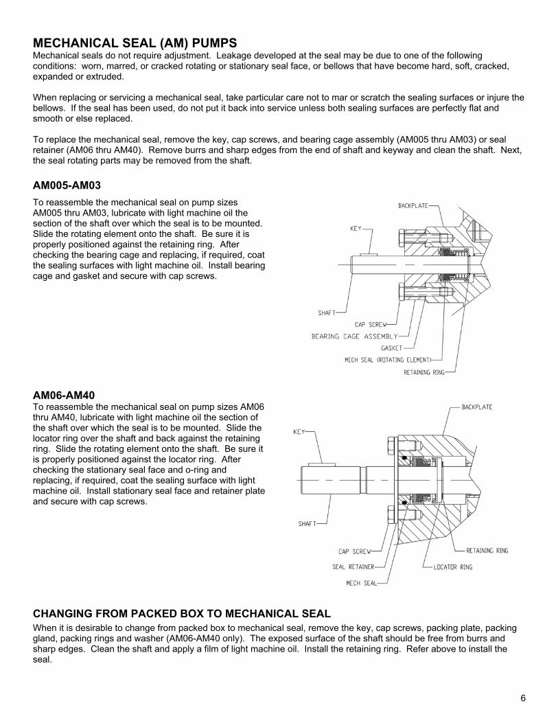
MECHANICAL SEAL (AM) PUMPS Mechanical seals do not require adjustment. Leakage developed at the seal may be due to one of the following conditions: worn, marred, or cracked rotating or stationary seal face, or bellows that have become hard, soft, cracked, expanded or extruded. When replacing or servicing a mechanical seal, take particular care not to mar or scratch the sealing surfaces or injure the bellows. If the seal has been used, do not put it back into service unless both sealing surfaces are perfectly flat and smooth or else replaced. To replace the mechanical seal, remove the key, cap screws, and bearing cage assembly (AM005 thru AM03) or seal retainer (AM06 thru AM40). Remove burrs and sharp edges from the end of shaft and keyway and clean the shaft. Next, the seal rotating parts may be removed from the shaft. AM005-AM03 To reassemble the mechanical seal on pump sizes AM005 thru AM03, lubricate with light machine oil the section of the shaft over which the seal is to be mounted. Slide the rotating element onto the shaft. Be sure it is properly positioned against the retaining ring. After checking the bearing cage and replacing, if required, coat the sealing surfaces with light machine oil. Install bearing cage and gasket and secure with cap screws.
AM06-AM40 To reassemble the mechanical seal on pump sizes AM06 thru AM40, lubricate with light machine oil the section of the shaft over which the seal is to be mounted. Slide the locator ring over the shaft and back against the retaining ring. Slide the rotating element onto the shaft. Be sure it is properly positioned against the locator ring. After checking the stationary seal face and o-ring and replacing, if required, coat the sealing surface with light machine oil. Install stationary seal face and retainer plate and secure with cap screws.
CHANGING FROM PACKED BOX TO MECHANICAL SEAL
When it is desirable to change from packed box to mechanical seal, remove the key, cap screws, packing plate, packing gland, packing rings and washer (AM06-AM40 only). The exposed surface of the shaft should be free from burrs and sharp edges. Clean the shaft and apply a film of light machine oil. Install the retaining ring. Refer above to install the seal.
6

LIP SEAL (AL) PUMPS AL pumps with lip seals must be run in the clockwise direction of rotation only. Maximum discharge pressure is 100 PSIG (6.9 BAR) and maximum inlet pressure is 5 PSIG (3 BAR). For a pump equipped with a lip seal, follow these instructions. Leaking lip seals should be replaced. Note the direction of the lip on the old seal. Carefully pry the defective seal from the bore, making certain that the bore is not scored or damaged. Clean the shaft and bore. Inspect the shaft for wear. If worn or scored, replace. The exposed surface of the shaft should be free from burrs and sharp edges. Lightly oil shaft and bore into which the lip seal is to be fitted. Be careful not to damage the sealing lip and be certain that the lip on the new seal is turned the same direction as the old seal. Slide the seal onto the shaft and press into the bore.
PACKED BOX (AP) PUMPS Operate the pump under normal conditions and, after a short run-in period, examine the packing for leakage. If leakage is excessive, stop the pump and follow the procedure described below. A slight leakage is a necessary and normal condition for packing and allows for expansion and proper seating. SIZES 005 THRU 03 SIZES 06 THRU 40
To replace packing, remove the key, cap screws or nuts, packing plate, packing gland, and packing rings. (Packing hooks are commercially available to assist in removing the packing rings.) Clean the shaft and adjacent parts. Examine the shaft. If it is excessively worn or scored, replace shaft and gear assembly. It is generally not recommended to reuse old packing rings. When installing packing, use formed packing rings. DO NOT use a one-piece spiral wrap of packing. Before installing packing, carefully clean the stuffing box and shaft. Packing rings should be installed one ring at a time, with the joints of adjacent rings staggered approximately 180°. Each ring should be seated firmly before the next ring is installed. The packing gland cap screws or nuts should first be evenly tightened with a wrench to seat the packing firmly in the stuffing box and against the shaft. DO NOT over-tighten the packing. The gland cap screws or nuts should then be backed off until finger-tight. After the pump is started, visually examine the stuffing box for excessive leakage. If the packing leakage exceeds ten drops per minute, stop the pump and adjust the gland nuts. The gland cap screws or nuts should be adjusted evenly in 1/6 to 1/3 turn (1 to 2 flats on the nut) increments. Start the pump and allow it to operate for several minutes. Again, visually examine the stuffing box for excessive leakage. Repeat the above procedure until the stuffing box leakage is between five to ten drops per minute. DO NOT over-tighten the packing. Slight leakage is a necessary requirement for proper packing operation. Leakage of five to ten drops per minute when the pump is operating is desirable, as it will preserve the packing and avoid scoring of the shaft. Over-tight packing may score shafts, increase torque requirements of the pump, damage couplings and drives, and generate excessive heat. The packing gland should be adjusted whenever leakage exceeds ten drops per minute. The condition of the packing should be checked at regular intervals, the frequency depending on the type of service. Experience will dictate how frequently the inspections should be made.
7

THIS PAGE INTENTIONALLY
LEFT BLANK


![[XLS]obcindia.co.in Dividend... · Web view300 300 300 300 300 300 300 300 300 300 300 300 300 300 300 300 300 300 300 300 300 300 300 300 300 300 300 300 300 300 300 300 300 300](https://static.fdocuments.us/doc/165x107/5aa6e5047f8b9ac5648b5d08/xls-dividendweb-view300-300-300-300-300-300-300-300-300-300-300-300-300-300.jpg)