Parts - 3DR Site Scan: The Complete Commercial Drone … · 1 Parts Tarot gimbal GoPro HERO3...
4
1 Parts Tarot gimbal GoPro HERO3 stabilization system IRIS+ mounting screws (2) Configuration cable Gimbals arrive preconfigured and ready to fly. For information on changing configuration and updating the firmware, visit 3dr.com/learn. Extra parts servo cable split-wire servo cable rail mounting hooks (2) X8/Y6/QUAD mounting hardware (instructions included) Remove the two screws securing the blue face plate, and remove the plate. 1 face plate remove Slide camera into housing with the lens nearest the top-right corner. 2 ! Important note: Make sure that the WiFi on your GoPro is turned OFF at all times when in use with IRIS+. remove 1 Attach Camera Place the blue face plate over the camera, and secure from the back with the two original screws. 3 Add face plate. tighten Thread cables here. Locate the black and white two-wire cable protruding from the bottom of IRIS. 1 Thread the cables through the interface plate. Locate the pins on the Tarot board. Connect the black wire to a - (ground) pin and the white wire to the T (tilt) pin. 2 Follow these instructions to connect the gimbal to IRIS. This will allow you to adjust the tilt of the camera in flight using the controller. To enable automatic camera stabilization without remote control, skip to the step 3: power. Attach black wire to ground (-). ground (black) tilt (white) Attach white wire to tilt (T). 2 Connect GoPro not included User Guide
Transcript of Parts - 3DR Site Scan: The Complete Commercial Drone … · 1 Parts Tarot gimbal GoPro HERO3...
1
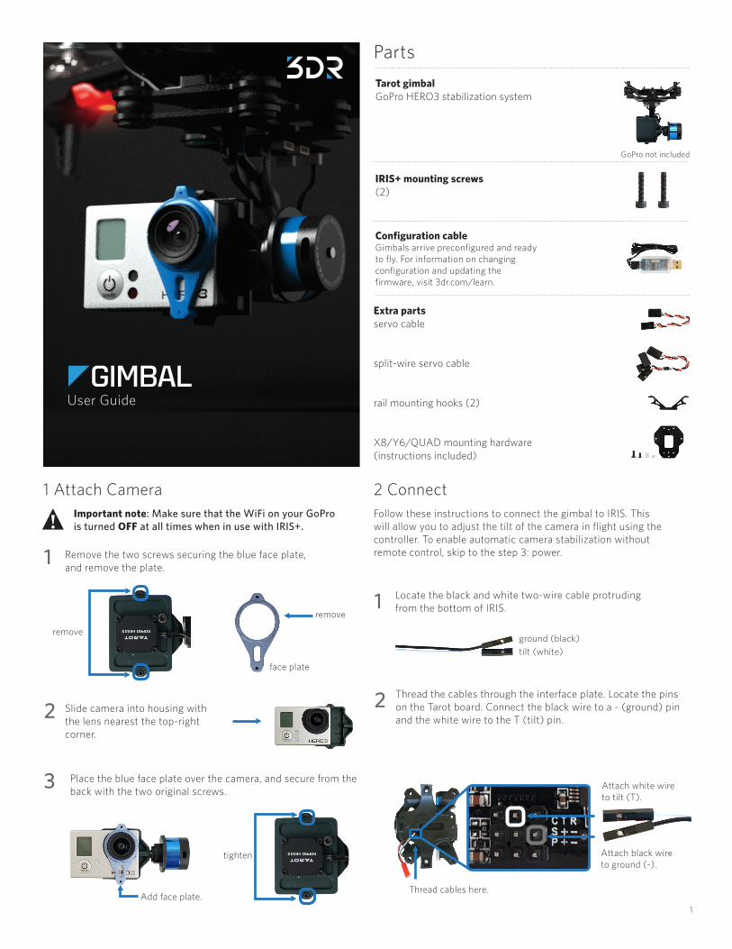
PartsTarot gimbalGoPro HERO3 stabilization system
IRIS+ mounting screws(2)
Configuration cableGimbals arrive preconfigured and ready to fly. For information on changing configuration and updating the firmware, visit 3dr.com/learn.
Extra parts servo cable
split-wire servo cable
rail mounting hooks (2)
X8/Y6/QUAD mounting hardware(instructions included)
Remove the two screws securing the blue face plate, and remove the plate.1
face plate
remove
Slide camera into housing with the lens nearest the top-right corner.
2
! Important note: Make sure that the WiFi on your GoPro is turned OFF at all times when in use with IRIS+.
remove
1 Attach Camera
Place the blue face plate over the camera, and secure from the back with the two original screws.3
Add face plate.
tighten
Thread cables here.
Locate the black and white two-wire cable protruding from the bottom of IRIS.1
Thread the cables through the interface plate. Locate the pins on the Tarot board. Connect the black wire to a - (ground) pin and the white wire to the T (tilt) pin.
2
Follow these instructions to connect the gimbal to IRIS. This will allow you to adjust the tilt of the camera in flight using the controller. To enable automatic camera stabilization without remote control, skip to the step 3: power.
Attach black wireto ground (-).
ground (black)tilt (white)
Attach white wire to tilt (T).
2 Connect
GoPro not included
User Guide

2
Connect the gimbal power cable with the red connector to the matching cable protruding from the bottom of IRIS.
3 Power
Using the mounting screws, attach the gimbal to IRIS through the two holes in the interface plate and the two holes in the bottom shell shown below.
Mount the gimbal with the camera facing forward.
4 Connect to IRIS
Operating the Gimbal
Upon powering IRIS, the gimbal will display a solid yellow light while it is starting and calibrating. Do not touch the gimbal while it is starting up. When the gimbal displays a blinking blue light, it is ready to fly.
If the gimbal is not connected to the autopilot, it will perform automatic stabilization without remote control, indicated by a solid blue light.
Calibrating, do not touch gimbal
Ready, connected to autopilot
Ready, not connected to autopilot
In flight, use the TILT knob on the controller to adjust the angle of the camera.
! Important note: Flying with a gimbal will reduce your flight time by as much as five minutes. Please plan your flights accordingly.
Connect gimbal to bottom shell here.
complete assembly
Specs• Supports GoPro HERO3 video auxiliary
output cable (sold separately)• Support for remote devices : PPM/
PCM/2.4G• Working voltage : DC 7.4V ~ 14.8V
(Recommended 12V)• Working current : 200 mA-500 mA • Working environment temperature:
-15°C ~ 65°C (5°F ~ 149°F)• Dual 32-bit high-speed ARM core
processors• Three axis MEMS gyroscope and MEMS
accelerometers• Maximum angular rate : 2000 °/sec• Control frequency: 2000 Hz
• Motor drive frequency: 20 kHz• Control accuracy : 0.1 ° (Pixel Grade)• Control angle range : -45 ° ~45 ° (roll),
-135 ° ~ 90 ° (tilt)• Pose solver algorithms : PTZ dedicated
brushless motor decoupled EKF algorithm• Weight without camera : 200 g• The Tarot gimbal should be powered by
a 2S or 3S LiPo battery only. If you plan to use 4S, please use a voltage regulator to ensure the voltage stays within safe operating limits.
• Firmware version 1.5
Rotate clockwise to level the camera.
Rotate counterclockwise to tilt the camera down.
3
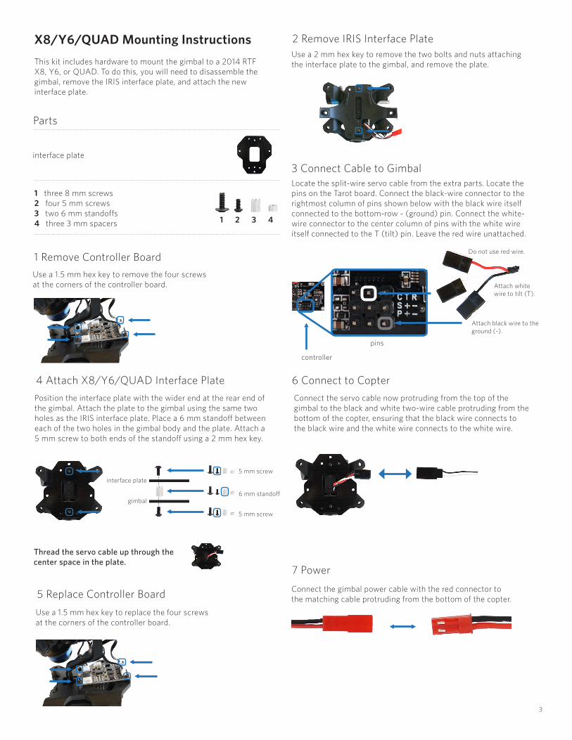
X8/Y6/QUAD Mounting InstructionsThis kit includes hardware to mount the gimbal to a 2014 RTF X8, Y6, or QUAD. To do this, you will need to disassemble the gimbal, remove the IRIS interface plate, and attach the new interface plate.
Use a 1.5 mm hex key to remove the four screws at the corners of the controller board.
1 Remove Controller Board
Use a 2 mm hex key to remove the two bolts and nuts attaching the interface plate to the gimbal, and remove the plate.
2 Remove IRIS Interface Plate
Use a 1.5 mm hex key to replace the four screws at the corners of the controller board.
5 Replace Controller Board
Position the interface plate with the wider end at the rear end of the gimbal. Attach the plate to the gimbal using the same two holes as the IRIS interface plate. Place a 6 mm standoff between each of the two holes in the gimbal body and the plate. Attach a 5 mm screw to both ends of the standoff using a 2 mm hex key.
4 Attach X8/Y6/QUAD Interface Plate
gimbal
interface plate5 mm screw
5 mm screw
6 mm standoff
Parts
1 2 3 4
interface plate
1 three 8 mm screws 2 four 5 mm screws3 two 6 mm standoffs4 three 3 mm spacers
controller
Attach black wire to the ground (-).
Attach white wire to tilt (T).
Do not use red wire.
Connect the servo cable now protruding from the top of the gimbal to the black and white two-wire cable protruding from the bottom of the copter, ensuring that the black wire connects to the black wire and the white wire connects to the white wire.
6 Connect to Copter
Locate the split-wire servo cable from the extra parts. Locate the pins on the Tarot board. Connect the black-wire connector to the rightmost column of pins shown below with the black wire itself connected to the bottom-row - (ground) pin. Connect the white-wire connector to the center column of pins with the white wire itself connected to the T (tilt) pin. Leave the red wire unattached.
3 Connect Cable to Gimbal
Thread the servo cable up through the center space in the plate.
7 Power
Connect the gimbal power cable with the red connector to the matching cable protruding from the bottom of the copter.
pins

4
Rotate clockwise to level the camera.
Rotate counterclockwise to tilt the camera down.
For Non-3DR Transmitters
To calibrate a non-3DR transmitter to control the gimbal, you will need to enable channel six for a knob on your transmitter during RC calibration in Mission Planner or APM Planner. Once channel six is enabled, the preconfigured Pixhawk settings will automatically assign gimbal control to the selected control knob on the transmitter.
If you are using a PPM encoder to connect to Pixhawk, you will need to connect channel six from your RC receiver to the encoder before calibration.
gimbal interface plate
copter base plate
8 mm screw
3 mm spacer
Y6 base plateconnect to
Quad/X8 base plate
To mount the gimbal to your copter, add an 8 mm screw to each of the three holes in the interface plate from below so that the threads protrude from the top of the interface plate. Add a 3 mm spacer to each screw above the interface plate, and attach the screws to the three holes in the base plate of the copter indicated below. The spacers should be between the gimbal interface plate and the base plate.
8 Mount to X8, Y6, or QUAD
interface plate
Operating the Gimbal
Upon powering the copter, the gimbal will display a solid yellow light while it is starting and calibrating. Do not touch the gimbal while it is starting up. When the gimbal displays a blinking blue light, it is ready to fly.
If the gimbal is not connected to the autopilot, it will perform automatic stabilization without remote control, indicated by a solid blue light.
Calibrating, do not touch gimbal
Ready, connected to autopilot
Ready, not connected to autopilot
For 3DR controllers, use the channel 6 knob to adjust the angle of the camera.
! Important note: Flying with a gimbal will reduce your flight time by as much as five minutes. Please plan your flights accordingly.
SpektrumFlySky
Remove the two screws securing the blue face plate, and remove the plate.1
face plate
remove
Slide camera into housing with the lens nearest the top-right corner.
2
! Important note: Make sure that the WiFi on your GoPro is turned OFF at all times when in use with a copter.
remove
9 Attach Camera
Place the blue face plate over the camera, and secure from the back with the two original screws.3
Add face plate.
tighten
Tarot Gimbal User Manual vA | ©3D Robotics, Inc. | 2 September 2014