Reinstein, “Asbestos: From Magic Mineral to Killer Dust" Izmir, Turkey

Nationel Bureau of Standards
Library, N. W. BIdg.
AUG 1 9 19524
Fire Tests of Wood-Framed Walls and
Partitions With Asbestos-Cement Facings
United States Department of CommerceNational Bureau of Standards
Building Materials and Structures Report 123

BUILDING MATERIALS AND STRUCTURES REPORTS
On request, the Superintendent of Documents, U. S. Government Printing Office, Wash-ington 25, D. C, will place your name on a special mailing list to receive notices of newreports in this series as soon as they are issued. There will be no charge for receiving suchnotices.
An alternative method is to deposit with the Superintendent of Documents the sum of $5,with the request that the reports be sent to you as soon as issued, and that the cost there-of be charged against your deposit. This will provide for the mailing of the publicationswithout delay. You will be notified when the amount of your deposit has become exhausted.
If 100 copies or more of any report are ordered at one time, a discount of 25 percent is
allowed. Send all orders and remittances to the Superintendent of Documents, U. S.
Government Printing Office, Washington 25, D. C.
The following publications in this series are available by purchase from the
Superintendent of Documents at the prices indicated:
BMSl Research on Building Materials and Structures for Use in Low-Cost Housing *
BMS2 Methods of Determining the Structural Properties of Low-Cost House Constructions. _ 100BMS3 Suitability of Fiber Insulating Lath as a Plaster Base 15jt
BMS4 Accelerated Aging of Fiber Building Boards 10(4
BMS5 Structural Properties of Six Masonry Wall Constructions 15^BMS6 Survey of Roofing Materials in the Southeastern States 15(§
BMS7 Water Permeability of Masonry Walls *
BMS8 Methods of Investigation of Surface Treatment for Corrosion Protection of Steel 150BMS9 Structural Properties of the Insulated Steel Construction Co.'s "Frameless-Steel"
Constructions for Walls, Partitions, Floors, and Roofs 100BMSlO Structural Properties of One of the "Keystone Beam Steel Floor" Constructions
Sponsored by the H. H. Robertson Co 100BMSll Structural Properties of the Curren Fabrihome Corporation's "Fabrihome" Con-
structions for Walls and Partitions 100BMS12 Structural Properties of "Steelox" Constructions for Walls, Partitions, Floors, and
Roofs Sponsored by Steel Buildings, Inc 150BMS13 Properties of Some Fiber Building Boards of Current Manufacture 100BMS14 Indentation and Recovery of Low-Cost Floor Coverings 100BMS15 Structural Properties of "Wheeling Long-Span Steel Floor" Construction Sponsored
by the Wheeling Corrugating Co 100BMS16 Structural Properties of a "Tilecrete" Floor Construction Sponsored by Tilecrete
Floors, Inc 100BMS17 Sound Insulation of Wall and Floor Constructions 200Supplement to BMS17, Sound Insulation of Wall and Floor Constructions 50Supplement No. 2 to BMS17, Sound Insulation of Wall and Floor Constructions 100BMS18 Structural Properties of "Pre-fab" Constructions for Walls, Partitions, and Floors
Sponsored by the Harnischfeger Corporation 100BMS19 Preparation and Revision of Building Codes tBMS20 Structural Properties of "Twachtman" Constructions for Walls and Floors Sponsored
by Connecticut Pre-Cast Buildings Corporation 100BMS21 Structural Properties of a Concrete-Block Cavity-Wall Construction Sponsored by
the National Concrete Masonry Association 100BMS22 Structural Properties of "Dun-Ti-Stone" Wall Construction Sponsored by the W. E.
Dunn Manufacturing Co 100BMS23 Structural Properties of a Brick Cavity-Wall Construction Sponsored by the Brick
Manufacturers Association of New York, Inc 100BMS24 Structural Properties of a Reinforced-Brick WaU Construction and a Brick-Tile
Cavity-Wall Construction Sponsored by the Structural Clay Products Institute. _ 150BMS25 Structural Properties of Conventional Wood-Frame Constructions for Walls, Parti-
tions, Floors, and Roofs 200BMS26 Structural Properties of "Nelson Pre-Cast Concrete Foundation" Wall Construction
Sponsored by the Nelson Cement Stone Co., Inc 100BMS27 Structural Properties of "Bender Steel Home" WaU Construction Sponsored by the
Bender Body Co 100BMS28 Backflow Prevention in Over-Rim Water Supplies 150BMS29 Survey of Roofing Materials in the Northeastern States 200BMS30 Structural Properties of a Wood-Frame Wall Construction Sponsored by the Douglas
Fir Plywood Association 150BMS31 Structural Properties of "Insulite" Wall and "Insulite" Partition Constructions
Sponsored by The Insulite Co 250
•Out of print.tSuperseded by BMS116 iT,
[List continued on cover page III]

UNITED STATES DEPARTMENT OF COMMERCE • Charles Sawyer, Secretary
NATIONAL BUREAU OF STANDARDS • E. U. Condon, Director
Fire Tests of Wood-Framed Walls and
Partitions With Asbestos-Cement
Facings
Nolan D. Mitchell
Building Materials and Structures Report 123
Issued May 10, 1951
For sale by the Superintendent of Documents, U.S. Government Printing Office, Washington 25, D. C.
Price 15 cents


ForewordWalls and partitions that retard the spread of fii'e contribute to the safety
of nonfire-resistive buildings.
The performance of wood-framed walls and partitions with facings of
asbestos-cement shingles or sheets, when subjected to fire tests under standard
procedures, is given in this paper. The information presented is intended to
aid building authorities and regulatory agencies in evaluating the fii'e-resistance
characteristics of constructions of these types and give the prospective builder
a basis for the selection of constructions that will meet given requirements
with respect to fire resistance.
E. U. Condon, Director.

CONTENTSPage
Foreword iii
I. Introduction 1
II. Materials. _.. 1
1. Lumber 1
2. Metal trim 1
3. Facing sheets 1
4. Shingles 1
5. Gypsum boards and strips 2
6. Asbestos felt 2
7. NaUs 2
8. Mineral wool 2
9. Asbestos paper 2
III. Construction 2
1. Framework 2
2. Wood sheathing 2
3. Gypsum sheathings 2
4. Nailing J 3
5. Painting 3
6. Trim 3
IV. Equipment and method of testing 3
V. Results of tests ' 6
1. Partition with asbestos-cement sheet facing, no insulation 6
2. Partitions sheathed with gypsum boards and faced with asbestos-
cement sheets, no fill between studs 8
3. Partitions with asbestos-cement sheet facing, mineral-wool fill 8
4. Partitions Avitli asbestos-cement sheet facing, mineral-wool fill,
and edges of studs sheathed with gypsum-board strips 9
5. Walls faced with asbestos-cement shingles 10
VI. Summary and discussion 13
TV

Fire Tests of Wood-Framed Walls and Partitions
With Asbestos-Cement Facings
Nolan D. Mitchell
Three walls and four partitions with asbestos-cement facings on wood frames weresubjected to fire-endurance tests and one wall and three partitions to fire and hose-streamtests. The partitions had asbestos-cement sheet facings on both sides over differing in-
ternal constructions. The edges of the studs of some of the partitions were lined withasbestos paper or gj'psum-board strips. One partition had no insulation, four had mineral-wool batt fill between the studs; two had gypsum-board sheathing underlying the asbestos-cement sheet facings. The walls had matched diagonal sheathing, asphalt-saturatedasbestos felt, and asbestos-cement shingles as the exterior facings. The interior facingswere of asbestos-cement sheets or asbestos-cement insulated sheathing. Three walls hadmineral-wool batt insulation between the studs. Fire-endurance limits for the partitions
ranged from 9 to 90 minutes. Failure by a limiting rise of temperature was not a determi-nant in any of the tests of the walls. The fire exposures ranged from 38 to 8.5 minutes.Limits by failure under load for the walls ranged from 32 to 79 minutes. Failure from im-pact of the hose stream occurred in one of three tests of the partitions and in the single hose-stream test of a wall.
I. Introduction
The use of asbestos-cement shingles as the ex-
terior coverings of wood-frame houses and build-
ings is of common occurrence in rural and semi-rural areas, and in urban locations where buUdingregulations permit. Asbestos-cement sheets havebeen used recently in housing projects as the inte-
rior facings of walls and on both sides of partitions.
Because no data on the fire resistance of such con-structions were available, tests were conductedat the National Bureau of Standards to establish
the fire-endiu'ance limits and the fu'e-resistance
characteristics of asbestos-cement materials suit-
able for low- or moderate-cost types of construc-tion.
With the purpose of securing data on both in-
terior and exterior constructions, seven partitions
and four walls, all with asbestos-cement facings
on wood frames, were tested. Interior facings
were of asbestos-cement sheets. The exterior fac-
ings of the walls were of asbestos-cement shingles
over wood sheathing. Several kinds of mineral-woolinsulating materials were used in the tests. Fom*partitions and three walls were subjected to fire-
endurance tests, and three partitions and onewall to fire and hose-stream tests. With the ex-
ception of the partitions subjected to the hose-stream test, all of the walls and partitions weretested under load.
II. Materials
1. Lumber
The framing of both the walls and the partitions
was made of 2- by 4-in. nominal size No. 1 commonDouglas fir. The dressed and matched sheathing
was No. 2 common North Carolina or Vu-ginia
pine, in. thick by SK-in. face width. Thetrim, for the most part, was "B or better" gradeWestern pine.
2. Metal Trim
The vertical joints of each section of three par-titions and of the interior facings of three walls
had cover strips of chromiiun- plated aluminumalloy.
3. Facing Sheets
The asbestos-cement facing sheets were of com-mon commercial quality. The full-sized pieces
were 4 ft wide by 8 ft long by in. thick. Oneface of the sheets was smooth, the other had asomewhat rough texture. Included were sheets
from four manufacturers. The insidated sheath-ing boards Avere 4 ft wide by 8 ft long by /i6 in.
thick, made up of /le-in. cane fiberboard faced onone side with %-'m. thick asbestos-cement sheet.
The asbestos-cement sheets used in these tests
were similar to those described as Type I in Fed-eral Specification SS-S-283, entitled Sheets; flat,
asbestos-cement.^
4. Shingles
The wood-grained asbestos-cement siding shin-
gles, having rough siu'faces simidating the grain of
split cypress, were supplied by two manufacturersin dimensions 24 in. by 12 in. by ?32-in. nominalthickness.
The shingles used in these tests complied withFederal Specification SS-S-346a, Siding (shingles
' Federal Specifications mentioned in this paper are obtainable from theSuperintendent of Documents, Government Printing Office, Washington26, D. C, for 5 cents each.
1

and clapboards);asbestos-cement, and had )^-in.-
diameter holes punched for nailing.
5. Gypsum Boards and Strips
The gypsum-board strips used for lining the
edges of the studs, facing the joints between the
frame and test frame of the furnace, were cutfrom %-in.-thick gypsum lath and from K-in.-thick
gypsum wallboard. The gypsum boards used as
sheathing under the asbestos-cerAent sheet facings
of the partitions in two tests were /s-in. and K-in.-
thick gypsum wallboards and ^2-in.-thick gypsumsheathing boards.
6. Asbestos Felt
Asphalt-satiu"ated asbestos felt applied betweenthe diagonal sheathing and shingles of the exterior
sides of the walls weighed 14 to 15 lb/100 ft^
Weather strips, 4 and 3 in. wide by 12 in. long cut
from smooth-surfaced roll roofing weighing ap-proximately 30 lb/100 ft^, were laid under thevertical joints between shingles of the same course.
7. Nails
Several types and sizes of nails were used in the
application of the facmg sheets. Joints to becovered by trim had, for the most part, flat-head
nails. The heads of naUs used in locations notcovered by trim were countersunk or driven flush.
Most of the sheets were nailed with l}2-in. nickel-
plated nails having 0.06-in. square wire shankstwisted one tm'n in a length of eight or nine timestheir thickness. The number of nails per poundwas about 715. Common wire nails for edgenailing and finish nails for intermediate nail-
ing used on some sheets were 6d. The shingles
were naUed with 4d galvanized nails in thecovered portions, and with the l/4-in.-long 13/2-
gage cadmium-plated, serrated-shank nails, fur-
nished with the shingles, in locations exposedto view.
8. Mineral Wool
The mineral wool employed, all in batt form,was supplied by local dealers. Thicknesses weredesignated as "semithick" and "full-thick", or by^similar terms, to difi^erentiate between the batts
of 2 in. and 3/2 in. nominal thickness. Most of the
batts were covered on one face with a waterproofpaper having edges extending about 1% in. beyondthe long edges of the batts. The weight of thebatts as received ranged from % Ib/ft^ to 1.2 Ib/ft^.
9. Asbestos Paper
The asbestos paper used as lining of the edgesof the studs of some partitions was cut in 4-in.-
wide strips from }^-m.-thick roll material.
III. Construction
For the purposes of these tests, the partitions
were divided into two sections, each being 8 ft longand 10/3 ft high except those for the fire and
hose-stream test which were only 8 ft high.Although the facmgs were alike on both sides of
each section, in some of the tests minor details
of the internal constructions of the sections
differed. The walls, which were of the samedimensions as the partitions for the fire-endurancetests, were also divided into two sections, so
placed as to expose the shingled side of onesection and the interior facing of the other to
the fire.
1. Framework
All structural framework was made of 2- by4-in. scantlings. The studs were spaced 16 in. oncenters, and toe-nailed to top and bottom plates.
The four walls and fom* of the partitions hadblocks set between the studs at 2% ft above thebottom to form supports for naUing the edges of
the boards along a horizontal joint. Blocks wereomitted from the walls that were only 8 ft high(see fig. 1).
All the wood frames were bolted to the test
frames with K-in.-diameter bolts through the top
SECTION ELEVATION
Figure 1. Details of a -partition faced with asbestos-
cement sheets.
and bottom plates. The bottom plates of the
partitions for fire-endurance tests and the plates
of the four walls were bolted to beams resting onrocker plates on top of the pistons of four hydraulicjacks. The partitions for fire and hose-streamtests 3, 5, and 7 were buUt into a frame giving
restraint against expansion in the plane of the wall.
2. Wood Sheathing
The wood sheathing boards were applied
diagonally to the walls with one or two nails at
each intermediate bearing and two naUs at each
end bearing.
3. Gypsum Sheathings
The end studs of sections of walls and partitions
that were to be tested under load were lined onthe side facing the open joint through the framingwith 3%- by %-in. gypsum-board strips, as shownin figure 1.
2

To afford some degree of protection against
early ignition, strips of gypsum board were ap-
plied along the edges of the wood studs of twopartitions (tests 6 and 7) and three walls (tests 9,
10, and 11). These strips were 4 in. wide. Forthe partitions they were of % in. thickness and for
the Ulterior facmgs of the walls of tests 10 and 11
of K in. thickness. The wall in test 8 had in-
sulated sheathing board for the interior facing.
The partitions in tests 2 and 3 had sheathing of
gypsum board over which the asbestos-cementsheets were applied, the gypsum board on section
A being % in. thick and on section B, % in. thick.
4. Nailing
The nailmg of the facing sheets varied in minordetails as experience was gained in the work. Thesheets were drilled with holes usually of suitable
size to receive the various naUs used. Thedrills were 0.087, 0.10, 0.12, 0.125, and 0.138 m.in diameter. The facing of the partition for test
1 was nailed along the edges with 6d commonwii'c nails, which were countersunk. Interme-diate nailing was done with 6d finish nails, also
countersunk.Most of the asbestos-cement sheets were naUed
with twisted square-wire nails with flat heads,countersunk. These naUs usually were driveninto holes without being countersimk, but as theholes were only slightly smaller than the nail-
head diameter, a cone of material was not drivenfrom the back of the sheet when the head was set
flush with the sheet surface.
5. Painting
The sheets of six specimens of this series werefinished with two coats of either clear varnish orrubbing varnish, or one coat of wax applied in
the form of a water emulsion. The wax waspolished when dry. The varnishes were rubbedbetween coats with sandpaper and steel wool.
6. Trim
The wood trim was nailed in place and givennatural wood finish with clear varnish. Thechromium-plated metal strips had been fabricatedwith nails spaced about 6 in. apart. The nail-
heads were fastened into dovetailed grooves alongthe center of the back of the strip. These wereapplied by driving the nails through the crackbetween the edges of the sheets into the studs.
IV. Equipment and Method ofTesting
The tests were made with a furnace that ac-commodates walls 16 ft long and 8 or lO^'s ft
high. The fom walls and foiu- of the parti-tions, those of lOK-ft height made with blocksbetween the studs, were subjected to load duringthe tests. The three partitions not subjected to
load (tests 3, 5, and 7) were subjected to tlio
hose stream after fire exposure. One; of tlu; walls
(test 11) was also subjected to the hose-streamtest while under the same load applied duringthe fire exposure. The load was applied bymeans of the hydraulic jacks set in the lower partof the test frame, (see fig. 2). The full loadapplied was 30,500 lb, or 360 Ib/in.^ of each stud.
The furnace was heated by 92 gas burners, all
controlled by one large valve, with a separate /4-in.
stopcock for each bm-ner. Nine thermocouplesof chromel-alumel wires were distributed through-out the furnace chamber to indicate temperatures.Measurements for controlling temperatm-es to
conform to a standard reference curve were madeat 5-min intervals during the first hour and at
10-min intervals thereafter. The required tem-peratm-es were 1,000° at 5 min, 1,300° at 10 min,1,550° at 30 mm, 1,700° at 1 hr, and 1,850°F at
2 hr, corresponding to temperatures of 538°, 704°,
843°, 927°, and 1,010° C, respectively.
Deflections of a wall or partition from a planesm-face were determined at nine points by measm-ing from the wall surface to vertical wnes stretched
opposite the center line and 4 feet each side of the
center line of the waU or partition.
Hose-stream tests were made by first exposingthe walls to fire and then projecting successively
against all parts of the heated surface the streamfrom a l)s-in. Under^TOters' pattern playpipeand fire-hose nozzle supplied with water at '30-
lb/in2. pressm'e through a 2}2-ui- rubber-lined
cotton fii'e hose. The water pressine was measur-ed at the base of the playpipe with a gage connect-
ed through a /s-in. diameter opening normal to
the direction of flow.
The tests were conducted in accordance with the
Standard Specifications for Fire Tests of BuildingConstruction and Materials of the AmericanStandards Association No. A2-1934, except that
load was not applied to the three partitions sub-
jected to the hose-stream test, and that each wall
and partition was divided into two panels, eachsmaller than the minimum size prescribed.
Temperatures were measured at five locations
on the unexposed surface of each panel (pomts P,
fig. 3), at either two or tkree points on the edges
of the studs toward the fire (points 1), and at the
same nmnber of points in the spaces between the
studs (points 2), as indicated in the construction
sketches in figures 3, 9, and 10. The thermo-couples on the unexposed surface were covered by6- by 6-m. asbestos felt pads 0.4 in. thick. Thosetoward the fire Avere laid in shallow grooves in the
edges of the studs before the facing materials wereapplied. Air temperature in the testing room wasmeasm'ed with a mercmy-m-glass thermometerat a point 12 ft from the center of the specimen.
Each partition with its test frame was placed to
form one wall of the combustion chamber of the
furnace. Previous to starting the fire, stress wasapplied to the wall or partition to be tested miderload, such load remaining constant thi'oughout
3

SECTION LONGITUDINAL SECTION HALF ELEVATIONI'" 0 1 ^ 3 4. s ip 15'
SCALE
Figure 2. Details of wall-testing furnace.
[A, furnace chamber; B, burners; C, thermocouple protection tubes; D, pit for debris; E, observation windows; F, air inlets; G, flue outlets and dampers,H, firebrick furnace lining; I, reinforced concrete furnace-shell; K, gas cocks; L, control valve; M, ladders and platforms to observation windows; N, movablefireproofed test frame; O, loading beam; P, hydraulic jacks; Q, test wall; R, asbestos felted pads covering thermocouples on unexposed surface of test wall.]
the fire-endurance test, or until failure occurred.When the wall or partition began to fail underload, the pressure in the jacks was reduced to pre-vent collapse. Usually the test fires were con-tinued beyond the time when the first criterion of
failure had been observed in order to determinethe subsequent behavior of the construction.At the end of the fire-exposure period for the
fire and hose-stream tests, the test frame was
withdrawn from the furnace and the hose streamapplied to the hot surface of the specimen. Thetip of the hose nozzle was held approximately 20ft away from the center of the specimen, and the
direction of the hose stream was changed slowlyand continuously to sweep the entire surface re-
peatedly. The period of application of the hosestream was VA min/100 ft^ of area of the wall.
In addition to determining the fire resistance of

EOOO
1900
y_ 1800
1700X2 1600IxJ
^ 1500
g 1400
1300LlI
LlI 1200tr(S> MOOUJQ 1000
2 900
LlI 800cr
^ 700
< 600
S 500
2 400
300
200
100
0
TEST NO I
A'aSBESTOS-CEMeiVT H
M>
-
'
\
\
Pa
A B
/i
Iav f1^
/1?;
R 1
30 60
TIME IN MINUTES
Figure 3. Furnace and -partition temperatures for partitions with no insulation between studs.
Tests 1, i, and 3.
the walls and partitions in accordance with the
test procedure, the limits, as surface finish of theasbestos-cement sheet facings or the shingled ex-
terior facings over combustible framing, wereascertained from the rise of temperature on theedges of the studs toward the fire. These limits
are indicated on the graphs of figures 3, 9, and 10.
The criteria of failure of bearing walls andpartitions are listed in paragraphs 13 (a), 13 (b),
and 13 (d) of the Standard Fire Test Specification.
Criteria for nonbearing walls are given in para-graphs 15 (a), 15 (b), and 15 (d). Failure
criteria for incombustible facings, or surface
finishes, over combustible members are given in
paragraphs 24 (a), 24 (b), and 24 (c), but are notcriteria of failure of a wall or partition. Para-graph 4 (d), defining the maximum limiting
temperature rise at one thermocouple, and para-graphs 9 (a) and 9 (b) relating to hose-streamtests, are applicable to the tests of this report.
Excerpts from the Standard Fire Test Specifica-
tion, including the pertinent sections, are as
follows:
4 (d) Where the Conditions of Acceptance place alimitation on the rise of temperature of the unexposedsurface, the temperature end point of the fire endur-ance period shall be determined by the average of themeasurements taken at individual points; exceptingthat, if a temperature rise 30 percent in excess of thespecified limit occurs at any one of these points, theremainder shall be ignored and the fire enduranceIDeriod judged as ended.
9 (a) Where required by the Conditions of Accept-ance, a duplicate sample shall be subjected to a fire-
exposure test for a period equal to one-half of thatindicated as the resistance period in the fire-endurancetest, but not for more than one hour, immediately afterwhich the sample shall be subjected to the impact,erosion and cooling effects of a hose stream directedfirst at the middle and then at all parts of the exposedface, changes in direction being made slowly.
9 (b) The hose-stream test shall not be required in
the case of constructions having a resistance period,indicated in the fire-endurance test, of one-half hour orless.
13 (a) The wall or partition shall have sustained theapplied load during the fire-endurance test withoutpassage of flame or gases hot enough to ignite cottonwaste, for a period equal to that for which classification
is desired.
13 (b) The wall or partition shall have sustained theapplied load during the fire and hose-stream test asspecified in Section 9, without passage of flame, ofgases hot enough to ignite cotton waste, or of the hosestream, and after cooling but within 72 hours after its
completion shall sustain a total load ecjual to the deadload plus twice the superimposed load specified above.
13 (d) Transmission of heat through the wall orpartition during the fire-endurance test shall not havebeen such as to raise the temperature on its unexposedsurface more than 250 degrees F (139 degrees C) aboveits initial temperature.
15 (a) The wall or partition shall have withstoodthe fire-endurance test without passage of flame orgases hot enough to ignite cotton waste for a periodequal to that for which classification is desired.
15 (b) The wall or partition shall have withstoodthe fire and hose-stream test as specified in Section 9,
without passage of flame, of gases hot enough to ignitecotton waste, or of the hose stream.
924041—51 2 5

15 (d) Transmission of heat through the wall orpartition during the fire-endurance test shall not havebeen such as to raise the temperature on its unexposedsurface more than 250 degrees F (139 degrees C) aboveits initial temperature.
24 (a) The finish shall have withstood the fire-
endurance test, without passage of flame, or of gaseshot enough to ignite the materials protected, for aperiod equal to that for which classification is desired.
24 (b) The finish shall have withstood the fire andhose-stream test as prescribed respectively for floors,
walls, and partitions as specified in Section 9, withoutpassage of flame, of gases hot enough to ignite thematerials protected, or of the hose stream.
24 (c) Transmission of heat through the finish dur-ing the fire-endurance test shall not have been such asto raise the temperature at its contact with the struc-tural members of the test panel or elsewhere on its
unexposed surface more than 250 degrees F (139 de-grees C) above the initial temperatures at thesepoints.
V. Results of Tests
In the sketches of specimens, figiu-es 3, 9, and10, F shows the location of a furnace thermocoupleand indicates the fire-exposed surface of the test
structure. Locations 1 and 2 P indicate thermo-couples in the wall or partition. Thermocouplesat location 1 are on the edge of the studs immed-iately beneath the fire-exposed face of the speci-
men and so are in position to indicate when thefacing has allowed sufficient transmission of heatto cause the limiting rise of temperature on thestud, which is one of the criteria of failure of a sur-
face finish over combustible framing members, para-graph 24 (c) of the standard fire test specification.
Thermocouples at location 2 are in the spaces
A
6
Figure 4. Designs of partiiions A to D, table 1, and walls
E to G, table 2.
between the studs or next to any insulating ma-terials applied in these spaces. Temperature rise
at this location has no bearing on the criteria of
failure. Thermocouples at location P are on theunexposed face of the specimen wall or partition,
and are protected from external atmosphericeffects by asbestos covering pads. These thermo-couples indicate the criterion of failure by rise of
temperature on the unexposed surface.
The principal characteristics of the partitionsand the results of the tests are given in table 1 andfigures 3, 4, and 9, and those for the walls in table
2 and figures 4 and 10.
In figures 3, 9, and 10, F is the furnace tem-perature, the adjacent broken lines indicate themaximum and minimum furnace temperatures,and the reference curve is the standard for furnacetemperatures. The subscripts A and B on thetemperature curves for the walls or partitions
indicate the location of the thermocouples bysection. Broken-line temperature curves, suf-
fixed MAX, are the maximum observed tempera-tures at any one thermocouple in a section, notnecessarily from the same thermocouple at all
times. Solid-line specimen temperatme curvesshow the average temperatures in a section at
1, 2, or P. Wliere AV follows the symbol for thethermocouple location, the values used were theaverages for the thermocouples of both sections.
The legends pertain to the criteria of failure de-fined in the standard fire-test specification in-
cluded in the foregoing section of this report.
1 . Partition With Asbestos-Cement Sheet Fac-ing, No Insulation
The limiting temperature rise of 250 deg F(139 deg C) on the unexposed face of this partition,
test 1, was reached at 9 min for section B, and at
10 min for section A. The limiting rise of 325deg F (181 deg C) at one point on the surface wasreached at 10 min for both sections A and B. Ata joint on the unexposed surface, where one sheet
had bulged away from the stud, flames appearedat 27 min after the start of the fire. Glow, whichwas observed on the chair rail of section A at 36min, developed into fiame at 39 min. Other datafor tests 1,2, and 3 are shown in figure 3. Loadfailures of sections A and B occurred at 35 and38 min, respectively.
Although buckling of the sheets on the fire-
exposed side pulled them loose from the nail headsfor lengths up to 30 in. along a few studs, onlytwo sheets broke up to the time that failure underload occurred (see fig. 5). Buckling of sheets onthe unexposed side also pulled nail heads throughin a few locations, but no breaks were observedin this test before the load failures. The deflec-
tions of the midpoints of the two sections A andB were 2.2 in. and 1.8 in., respectively, at 30 minafter the start of the test.
6

Table 1. Sumtnary of fire tests of wood-stud partitions with asbestos-cement sheet facings.
All studs were 2- by 4-in. Douglas fir spaced 16 in. on centers.
Testand
sectionNo.
lA-
IB.
2A.
2B.
3A-
3B.
4A.
4B.
5A.
SB.6A-
6B.
7A.
7B.
Construction
Thick,ness
4
4
4
4W
4%
De-sign:
Facings
Kind
Asbestos-cement .sheet.
.dot
Asbestos-cement sheetplus H'in. gypsumboard.
Asbestos-cement sheetplus yi-in. gypsumboard.
Same as 2A
Same as 2B
.
Asbestos-cemont sheet.
_do-
_d0-
.do.Asbestos-cement sheet;
gypsum-board strios
on edges of studs.
-dO-
_do.
.do.
Thickness
Insulation
Kind
None-
.do.
None between studs.
.do.
.do.
.do.
Full-thick mineral-wool batts.
.do.
.do.
.do-
1 full-thick, 1 semi-thick mineral-woolbatt.
2 full-thick mineral-wool batts.
1 full-thick, 1 semi-thick mineral-woolbatt.
2 full-thick mineral-wool batts.
Weight
1.0
1.0
1.0
1.97
2. 26
2. 10
2.10
Test data
Kind of
test
Fire andload.
.do.
.do.
-do.
Fire andhose.
.do.
Fire andload.
do
Fire andhose.
....do
Fire andload.
-...do
Fire andhose.
...-do....-
Limits
Kind
Temp., avg.i.
Temp., max.iLoad ,
(Temp., avg...-<Temp., max...iLoadITemp., avg...<Temp., ma.x...[LoadITemp., avg...•^Temp., max...[LoadfFire exposure.iHose.. -.
fFire exposure.IHose
(Temp., avg-.<Temp., max-.[Load
iTemp.,avg..
Temp., max..LoadHole through.
do
fTemp., avg. .
.
Temp., max...Load(Temp., avg.-.^Temp., max...[Load/Fire exposure.\Hose
/Fire e-xposure.IHose
Time
103864
6462NoneNone7945
2H
452^
Notes
30
30IVio
Partition failed by rise of
temperature on unex-posedsurfacc. Flame onunexposed surface ap-peared at 27 min.
1 Temperature limits notJ reached in 1 hr 30 min.
IMet requirements for rat-
/ ing 1 hr, combustible.Met requirements for rat-
ing as load-bearing I'Ahr, combustible. Metrequirements for ratingas nonload bearing I'/i
hr, combustible.Failed under load beforelimiting rise of surfacetemperature.
30-min. fire exposure; hoseapplied.Do.
Loading equipment failed.
Load applied after fire
test, 332 lb/in. 2 of studs.
)Loading equipment failed.
Load applied after fire
test, 344 lb/in2 of studs,
iMet requirements for 1 hr
fire resistance. (1 hr.combustible).
Do.
' Temperaturolaverat'cs and iiia.xiiiiuni^, rcsprct ivrly, on the unexposed surface.-; mca.sinrd at points P, figures 3 and 9. • See figure 4.
FinuRE 5. Exposed side of nsbestos-ceinent sheet-faced pailition, no insulation, after failure under fire and load. Test 1.
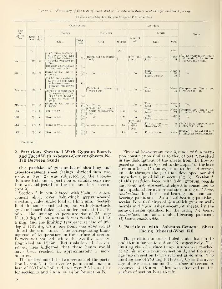
Table 2. Summary of fire tests of uwod-stitd walls with ashcstos-cemcnt shingle and sheet facings
All studs were 2- by 4-in. Douglas fir spaced 16 in. on centers.
Construction
Thick-ness
5H
5ji
5%
De-sign '
Facings
Kind
D&M pine sheathing,as bestos-felt andasbestos-cementshingles (e.xposed to
fire).
Insulated sheathing(unexposed side).
fSame as 8A, but re-
1 versed.
D&M pine sheathing,asbestos-felt andasbestos-cementshingles (exposed tofire).
Asbestos-cement sheet(unexposed side).G y p s um - b 0 a r dstrips on edge oi
. studs.[Same as 9A, but re-
[ versed.
Same as 9A
Same as 9B
Same as 9A
Same as 9B
Thick-ness
Vie11/8
1%
Insulation
Kind
[insulated sheathing
[only.
.do_
Full-thick mineral-wool batts.
_do^
1 Full-thick. 1 semi-thick mineral-woolbatt.
_do)-
}....do_
}_...do_
Weight
1. 05
1.73
1. 73
1.7
1.9
Test data
Kind of
test
Fire andload.
_do_
-do_
.._.do
_.-.do
...-do
Fire andhose,withload.
--.-do
Limits
Kind
/Temp.-- -
ILoad
(Temp<Load(.Flame through
ITemp-\Load
fTempILoad
(TempiLoad--
ITempILoad
iFire exposure
.
[Hole through-
.
Fire exposure -
.
Time
None34
None32
33
None51
None42
None74
None79
38
None
Notes
Surface temperature limitsat points P, fig. 1(J, notreached in 38 min.
Do.
ITemporature limits not/ reached in 1 hr.
Do.
ITemperaturc limits not/ reached in 1 hr. 25 min.
Do.
(Failed from impact of hose/ stream in ?3 min.
(Section B did not fail in 2
1 min 24 sec hose-stream test.
1 See figure 4.
2. Partitions Sheathed With Gypsum Boardsand Faced With Asbestos-Cement Sheets, NoFill Between Studs
One partition of gypsum-board sheathing andasbestos-cement sheet facings, divided into twosections (test 2) was subjected to the fire-en-
durance test, and a partition of similar construc-
tion was subjected to the fire and hose stream(test 3)
.
Section A in test 2 faced with %6-in. asbestos-
cement sheet over %-in. -thick gypsum-boardsheathing failed under load at 1 hr 2 min. Section
B of the same construction, but with Js-in.-thick
gypsum board failed, also under load, at 1 hr 19
min. The limiting temperature rise of 250 degF (139 deg C) on section A was reached at 1 hr4 min, and the limiting temperature rise of 325deg F (181 deg C) at one point was observed at
almost the same time. The corresponding limit-
ing rises of temperature on the surface of section
B were not reached before the gas fire was ex-
tinguished at IK hr. Extrapolation of the ob-
served rises indicated that these limits wouldhave been reached in approximately 5 moreminutes.The deflections of the two sections of the parti-
tion in test 2 at their center points and under a
load of 360 lb/in. ^ of stud area were 2.5 in. at 1 hr
for section A and 2.6 in. at \){ hr for section B.
Fire and hose-stream test 3, made with a parti-
tion construction similar to that of test 2, resultedin the dislodgment of the sheets from the fire-ex-
posed side when subjected to the impact of the hosestream after a 45-min exposure to fire. However,no hole through the partition developed nor didany other type of failure occur (fig. 6). Section Aof this partition faced with /g-in. gypsum boardsand %6-in. asbestos-cement sheets is considered to
have qualified for a fire-resist%hce rating of 1 hour,
combustible for both load-bearing and nonload-bearing partitions. As a load-bearing partition,
section B, with facings of /2-in.-thick gypsum wall-
boards and /{e-in. asbestos-cement sheets, by thesame criterion qualified for the rating l)i hours,
combustible, and as a nonload-bearing partition,
1)2 hours, combustible.
3. Partitions with Asbestos-Cement SheetFacing, Mineral-Wool Fill
The partition in test 4 failed under load at 40and 46 min for sections A and B, respectively. Thelimiting rise of surface temperatures was reachedat 42 min at one point on section A, and the aver-
age rise on section B was reached at 46 min. Thelimiting rise of 250 deg F (139 deg C) as the aver-
age of five locations on the surface of section Aoccurred at 48 min. Glow was observed on the
surface of section B at 46 min.
8

FiouRE G. Exposed si(le oj partition with gypsum sheathing under asbestos-cement sheets after 4-5 minexposure to fire followed by hose stream,. Test 3.
At 30 min after the start of the test, the mid-point of section A had deflected 2.2 in. away fromthe fire. The corresponding deflection of section Bwas 2.0 in. Each had deflected 1.4 in. farther at36 min and another inch at 40 min.
A partition of similar construction except for
asbestos-paper Uning on the edges of the studs ofone section (test 5) failed in 1 min from impact ofthe hose stream following a 30-mm exposure to
fire. The impact of the stream forced the sheetsoff the countersunk nail heads of the unexposedsurface, the sheets having been broken and dis-
lodged very quickly from the fire-exposed surfaceon application of the stream. The depth of charobserved on the edges of the studs toward the fire
varied from ^2 to % in., and was estimated toaverage about % in. This resulted from a 30-minexposure of the wall to fire. No noticeable efl^ect
was observed in the asbestos paper on the edges ofthe studs, probably because the fire exposure wasterminated before any limiting criterion of fire
resistance was attained (see fig. 7).
4. Partitions With Asbestos-Cement SheetFacing, Mineral-Wool Fill, and Edges ofStuds Sheathed with Gypsum-Board Strips
The partitions for tests 6 and 7 had 4-in.-widestrips of %-in.-thick gypsum board tacked alongboth edges of the wood studs before the asbestos-cement sheet facing was applied. The spacesbetween the studs of section A were filled withtwo thicknesses of mineral-wool batts, one plybeing of full-thick batts and the other of semi-thick batts. Section B had two plies of full-
thick batts.
FigUKE 7. Unexposed side of partition with mineral-woolfill after failure under load. Test A.
9

After the first 13 min of test 6, only section Aof the partition was subjected to load and that to
the extent of 210 lb/in. ^ of the wood studs. After
the fire exposure of 1-hr 32-min duration had beenterminated, and the pump that had failed wasrepahed, section A was subjected to a load of
13,750 lb, or 332 lb/in. ^ of the studs, and section
B to 14,200 lb, or 344 Ib/in.^ of the studs, before
failiu-e occm-red.
Failure hy a temperature rise of 325 deg F (181
deg C) at one point of section A of the partition
of test 6 occurred at 1 hr 19 min and on section
B at 1 lir 22 min. The limiting rise of 250 deg F(139 deg C) as the average of five locations wasreached at 1 hx 23 min on section A and at 1 hr 31
min on section B. Deflections of the midpoints of
sections A and B toward the fire at 1 hr 25 minwere 0.6 and 0.7 in., respectively. There was onlyminor cracking of the facing sheets on the unex-posed surface. Figure 8 shows the face' of thepartition after 1-hr 32-min exposure to fire.
The fire and hose-stream test of a similar
partition (test 7) resulted in dislodgment of the
facing sheets and gypsum-board strips from the
exposed side and of the mineral-wool batts frombetween the studs, but no holes were brokenthrough the sheets on the unexposed face. Exceptfor size of panel, this partition met the require-
ments for the fire-resistance rating, 1 hour, com-bustible.
Data for the partitions with mineral-wool fill
between the studs, tests 4, 5, 6, and 7, are shownin figure 9.
5. Walls Faced With Asbestos-Cement Shingles
Three walls with asbestos-cement shingles onone side and asbestos-cement sheets on the otherwere subjected to fire-endm-ance tests, and onewall to a fire and hose-stream test. Each wallwas divided into two equal sections, section Ahaving the shingled face exposed to the fire, andsection B with the sheet-faced side so exposed.All three walls subjected to the fire-endurancetest failed by buckling of the studs under load.
The limiting rise of temperature as measured bythermocouples under asbestos pads on the unex-posed sm'face was not attained during the fire
exposure in any of the three tests, the fires of
which were continued for periods of 38 min, 1 hr,
and 1 hr 25 min for tests 8, 9, and 10, respectively.
Data for the walls (tests 8, 9, 10, and 11) are
shown in figure 10.
The wall having the interior facing of a com-posite insulated sheathing board and with nomineral-wool fill between studs, nor strips of
gypsum-board lining the edges of the studs (test
8), failed in section B after a 32-min exposure to
fii'e and in section A after a 34-mm exposure (see
fig. 11).
The wall having the edges of the studs lined
with 4-in. by %-in.-thick gypsiun-board strips be-
fore the asbestos-cement sheets were applied, andwith a single-layer fill of full-thick batts of mineralwool weighing 1.05 Ib/ft^ (test 9) failed underload in section B after a 42-min exposure and in
•section A after a 51-min exposure to fire. Fullytwo-thirds of the cross-sectional area of the studs
10

TIME IN MINUTES
Figure 10. Furnace and wall temperatures for walls with asbestos-cement shmgles. Tests 8, 9, 10,
and 11.
was charred in the 1-hr fire-exposure period. Thedeflection away from the fire of the midpoint of
section B was 1.9 in. at 36 min, and of section A,2.9 in. at 45 min (see fig. 12).
The wall in test 10, similar to that in test 9 butwith Jo-in.-thick gypsum-board strips on the edges
of the studs, and insulated between studs withtwo layers of mineral-wool batts weighing a total
11


of 1.73 Ib/ft^, failed under load in section A at 1
hr 14 mill, and in section B at 1 hr 19 min. At 1
hr 10 min, the deflections of sections A and Bwere 2.8 and 2.7 in., respectively.
The wall in test 11 was similar to the wall in
test 10, except that the semithick mineral-woolbatts in the second of the two layers of batts wej-e
different, one fill having a total weight of 1.7 andthe other a weight of 1.9 lb/ft". This wall was ex-
posed to the test fire for 38 min, and then sub-jected to the impact of a fire-hose stream for 2
min 24 sec. A part of one of the asbestos-cementfacing sheets was torn away from the studs of
section A after a 40-sec application of the hosestream. Other pieces of asbestos-cement sheet
were broken away in rapid succession until little
except the piece applied horizontally below the
chair rail remained. It can be assumed that this
sheet, too, would have been torn away had it not
been held at both edges by wooden trim in addi-
tion to the regular nailing to the studs.
None of the asbestos-cement shingle coveringof section B was dislodged by tlie hose stream.
It was discovered after the hose-stream test thatthe holes for nailing the asbestos-cement sheets
had been made with a 0.1 18-in.-diameter drill.
When the casing nails, having heads 0.143 to 0.146in. in diameter, were driven flush, cones werebroken out from the back of the sheet around thenails, thus leaving the sheets with little supportfrom the nail heads. A drill 0.130. in. in diameterwas used on other sheets nailed in place the sameas those for the test panel. No wood trim wasapplied over the nail heads. These did not breakcones from the back of the sheets. The panelswithstood a hose-stream test at 30- and 40-lb/in.^
pressures, but the sheets were broken away whenthe pressure was raised to 50 lb/in.-
VI. Summary and Discussion
The framework of the partitions and walls wasthe common type wood-stud partition frame.
Eight frames had blocks fltted between the studs
to form supports for the edges of the sheets at
horizontal jomts.
The asbestos-cement sheets were of the commoncommercial grades produced by four manufac-turers. No distinction was made among them as
to use, nor were any consistent differences in
results noticeable in the tests. The attachmentof the sheets to the studs in a manner that wouldleave the nail heads flush with the surface wasdifficult. It is believed that a different type of
j
attachment, or at least holes made with a com-
I
bined drill and countersink of a size suitable for
the nail used, would be advantageous.The low resistance to fire of a partition faced
I with /i6-in.-thick asbestos-cement sheets only, and!with no insulation between studs or on the edge of
the studs, was due to heat transmission throughthe sheets, and warpage of the sheets to allowflames to issue on the unexposed face.
The varnishes and waxes used as surface finishes
on the specimens had no noticeable effect on theresults.
Mineral-wool fills made decided improvementin fire resistance of walls and partitions, particu-
larly with reference to heat transmission. Theuse of two thicknesses of mineral-wool batts andstrips of gypsum board to protect the edges of thestuds gave 1-hr resistance to fire before the limit-
ing temperatures were observed on the unexposedsurface. This type of construction failed in thefire and hose-stream test.
The tests of partitions sheathed with gypsumboards over which Ke-in- asbestos-cement sheetswere applied gave the best results in this series.
Such construction with /g-in.-thick gypsum boardgave a performance indicating a fire-resistance
rating of 1 hour, combustible and withstood thehose-stream test after a 45-min fire exposure.
Similarly, the partition with /o-in. gypsum-boardsheathing and faced with /le-in. asbestos-cementsheets gave a performance to indicate a rating of
Iji hours, combustible as a load-bearing wall, or
1/i hours, combustible as a n onload-bearing wall.
The partitions with facings of asbestos-cementsheets over gypsum-board sheathing had somewhatgreater fire resistance, as determined from limiting
rise of temperature on the unexposed face, thanpartitions with gypsum lath and plaster facings of
approximately the same thickness.^ In test 2 of
this series, a section of a partition made with/16-in. asbestos-cement sheets over %-m. gypsumboard did not reach a limiting rise of temperaturein a fire exposure of 1 lir 30 min. Partitions withplaster facings over several types of gypsum lath
and having a total lath and plaster thicloiess of
% in. on each side, attained limiting rises of temper-ature in times ranging from 47 min to 1 hr 29 min.The wood-stud walls covered with asbestos-
cement shmgles over asbestos felt, applied ondressed and matched wood sheathing and facedon the interior side with asbestos-cement sheets,
failed under load at 32, 42, and 74 min for those
with cane fiberboard, single fidl-thick batt, andone full-thick plus one semithick batt insulations,
respectively. The latter type, after being sub-
jected to fire for 38 min, failed in the hose-streamtest. This failure, as was similarly noted for the
partitions, could be attributed in part to improperor unsuitable iiaUmg of the boards.
It was difficult to secure the asbestos-cement
sheets to the studs in a manner that would leave
their smooth surfaces mibleniished without at
the same time inipairmg the strength of the
attachment. The method of nailing was a con-
tributing factor to the failure in fire tests and also
in the fire and hose-stream tests. Careful nailing
in countersunk holes would obviate this difficult}'
.
2 Fire Tests of Wood- and Metal-Framed Partitions, BMS71, NationalBureau of Standards (1941).
13

The adoption of a more suitable method of attach-
ing the sheets would also allow their use in manytypes of construction, especially as outer protec-
tive covering for gypsum board. The good per-
formance of this combination, as shown herein,
arises from the high structural and fire-resistant
characteristics of the asbestos-cement sheets andthe insulating properties of the gypsum boards.
Such construction may be expected to demonstratefire resistance superior to that of gypsum lath
and plaster of equal or even somewhat greater
thickness.
Acknowledgment is made to those manufac-turers of asbestos-cement sheets and shingles whosupplied the materials used for facings of thespecimens, and to S. H. Ingberg, former Chief of
the Fire Resistance Section of the NationalBureau of Standards, who planned and super-vised the tests. The author expresses apprecia-tion for the assistance given by other membersof the present Fire Protection Section.
Washington, September 29, 1950.
U S. GOVERNMENT PRINTING OFFICE: 1951

li
i

BUILDING MATERIALS AND STRUCTURES REPORTS[Continued from cover page ii]
BMS32 Structural Properties of Two Brick-Concrete-Block Wall Constructions and a Con-crete-Block Wall Construction Sponsored by the National Concrete MasonryAssociation 15(4
BMS33 Plastic Calking Materials 15^BMS34 Performance Test of Floor Coverings for Use in Low-Cost Housing: Part 1 15^BMS35 Stability of Sheathing Papers as Determined by Accelerated Aging *
BMS36 Structural Properties of Wood-Frame Wall, Partition, Floor, and Roof Construc-tions With "Red Stripe" Lath Sponsored by The Weston Paper and Manufac-turing Co 10^
BMS37 Structural Properties of "Palisade Homes" Constructions for Walls, Partitions, andFloors, Sponsored by Pahsade Homes *
BMS38 Structural Properties of Two "Dunstone" Wall Constructions Sponsored by theW. E. Dunn Manufacturing Co 10j5
BMS39 Structural Properties of a Wall Construction of "Pfeifer Units" Sponsored by theWisconsin Units Co 10{5
BMS40 Structural Properties of a Wall Construction of "Knap Concrete Wall Units" Spon-sored by Knap America, Inc 15j5
BMS41 Effect of Heating and Cooling on the Permeability of Masonry Walls *
BMS42 Structural Properties of Wood-Frame Wall and Partition Constructions with "Celo-tex" Insulating Boards Sponsored by The Celotex Corporation 15(5
BMS43 Performance Test of Floor Coverings for Use in Low-Cost Housing: Part 2 15j5
BMS44 Surface Treatment of Steel Prior to Painting 10^5
BMS45 Air Infiltration Through Windows 15«5
BMS46 Structural Properties of "Scot-Bilt" Prefabricated Sheet-Steel Constructions for
Walls, Floors, and Roofs Sponsored by The Globe-Wernicke Co *
BMS47 Structural Properties of Prefabricated Wood-Frame Constructions for Walls, Par-titions, and Floors Sponsored by American Houses, Inc 20(i
BMS48 Structural Properties of "Precision-Built" Frame Wall and Partition ConstructionsSponsored by the Homasote Co 15(5
BMS49 Metallic Roofing for Low-Cost House Construction 20^BMS50 Stability of Fiber Building Boards as Determined by Accelerated Aging 10(4
BMS51 Structural Properties of "Tilecrete Type A" Floor Construction Sponsored by theTilecrete Co 10^
BMS52 Effect of Ceiling Insulation Upon Summer Comfort 15(5
BMS53 Structural Properties of a Masonry Wall Construction of "Munlock Dry Wall Brick"Sponsored by the Munlock Engineering Co 10(5
BMS54 Effect of Soot on the Rating of an Oil-Fired Heating Boiler 10^5
BMS55 Effects of Wetting and Drying on the Permeability of Masonry Walls 10(5
BMS56 A Survey of Humidities in Residences 10(5
BMS57 Roofing in the United States—Results of a Questionnaire *
BMS58 Strength of Soft-Soldered Joints in Copper Tubing 10(5
BMS59 Properties of Adhesives for Floor Coverings 15^BMS60 Strength, Absorption, and Resistance to Laboratory Freezing and Thawing of Build-
ing Bricks Produced in the United States 30(5
BMS61 Structural Properties of Two Nonreinforced Monolithic Concrete Wall Constructions. 10(5
BMS62 Structural Properties of a Precast Joist Concrete Floor Construction Sponsored bythe Portland Cement Association 10^
BMS63 Moisture Condensation in Building Walls 150BMS64 Solar Heating of Various Surfaces 10(5
BMS65 Methods of Estimating Loads in Plumbing Systems 15j5
BMS66 Plumbing Manual 35^BMS67 Structural Properties of "Mu-Steel" Prefabricated Sheet-Steel Constructions for
Walls, Partitions, Floor, and Roofs, Sponsored by Herman A. Mugler 15(5
BMS68 Performance Test for Floor Coverings for Use in Low-Cost Housing: Part 3 20(5
BMS69 Stability of Fiber Sheathing Boards as Determined by Accelerated Aging 10(5
BMS70 Asphalt-Prepared Roll Roofings and Shingles 200BMS71 Fire Tests of Wood- and Metal-Framed Partitions 200BMS72 Structural Properties of "Precision-Built, Jr." Prefabricated Wood-Frame Wall
Construction Sponsored by the Homasote Co 100BMS73 Indentation Characteristics of Floor Coverings 100BMS74 Structural and Heat-Transfer Properties of "U. S. S. Panelbilt" Prefabricated Sheet-
Steel Constructions for Walls, Partitions, and Roofs Sponsored by the TennesseeCoal, Iron & Railroad Co 200
BMS75 Survey of Roofing Materials in the North Central States 150BMS76 Effect of Outdoor Exposure on the Water Permeability of Masonry Walls 150BMS77 Properties and Performance of Fiber Tile Boards 100BMS78 Structural Heat-Transfer, and Water-Permeability Properties of Five Earth-Wall
Constructions 250BMS79 Water-Distributing Systems for Buildings 200BMS80 Performance Test of Floor Coverings for Use in Low-Cost Housing: Part 4 150BMS81 Field Inspectors' Check List for Building Constructions (cloth cover, 5 x 754 inches).. 300
•Out of print.
[List continued on cover page iv]

BUILDING MATERIALS AND STRUCTURES REPORTS[Continued from cover page iii]
BMS82 Water Permeability of Walls Built of Masonry Units . 25^BMS83 Strength of Sleeve Joints in Copper Tubing Made With Various Lead-Base Solders 15^BMS84 Survey of Roofing Materials in the South Central States 15^BMS85 Dimensional Changes of Floor Coverings With Changes in Relative Humidity and Tem-
perature 10j5
BMS86 Structural, Heat-Transfer, and Water-Permeability Properties of "Speedbrik" WallConstruction Sponsored by the General Shale Products Corporation 15j5
BMS87 A Method for Developing Specifications for Building Construction—Report of Sub-committee on Specifications of the Central Housing Committee on Research,Design, and Construction 15jJ
BMS88 Recommended Building Code Requirements for New Dwelling Construction WithSpecial Reference to War Housing *
BMS89 Structural Properties of "Precision-Built, Jr." (Second Construction) PrefabricatedWood-Frame Wall Construction Sponsored by the Homasote Co 15j5
BMS90 Structural Properties of "PHC" Prefabricated Wood-Frame Construction for Walls,Floors, and Roofs Sponsored by the PHC Housing Corporation 150
BMS91 A Glossary of Housing Terms 15^BMS92 Fire-Resistance Classifications of Building Constructions 30^BMS93 Accumulation of Moisture in Walls of Frame Construction During Winter Exposure 10^BMS94 Water Permeability and Weathering Resistance of Stucco-Faced, Gunite-Faced, and
"Knap Concrete-Unit" Walls 15j5
BMS95 Tests of Cement-Water Paints and Other Waterproofings for Unit-Masonry Walls 25^BMS96 Properties of a Porous Concrete of Cement and Uniform-Sized Gravel 10^BMS97 Experimental Dry. Wall Construction With Fiber Insulating Board 10^BMS98 Physical Properties of Terrazzo Aggregates 15^BMS99 Structural and Heat-Transfer Properties of "Multiple Box-Girder Plywood Panels"
for Walls, Floors, and Roofs 15^BMSlOO Relative Slipperiness of Floor and Deck Surfaces 10^BMSlOl Strength and Resistance to Corrosion of Ties for Cavity Walls 10^BMS102 Painting Steel 10(4
BMS103 Measurements of Heat Losses From Slab Floors 15^BMS104: Structural Properties of Prefabricated Plywood Lightweight Constructions for Walls,
Partitions, Floors, and Roofs Sponsored by the Douglas Fir Plywood Association. _ 300BMS105 Paint Manual With Particular Reference to Federal Specifications $L25BMS106 Laboratory Observations of Condensation in Wall Specimens 150BMS107 Building Code Requirements for New Dwelling Construction *
BMS108 Temperature Distribution in a Test Bungalow With Various Heating Devices 100BMS109 Strength of Houses: Application of Engineering Principles to Structural Design $1.50BMSllO Paints for Exterior Masonry Walls 150BMSlll Performance of a Coal-Fired Boiler Converted to Oil
, 150BMS112 Properties of Some Lightweight-Aggregate Concretes With and Without an Air-Entrain-
ing Admixture 100BMS113 Fire Resistance of Structural Clay Tile Partitions 150BMS114 Temperature in a Test Bungalow With Some Radiant and Jacketed Space Heaters 250BMS115 A Study of a Baseboard Convector Heating System in a Test Bungalow 150BMS116 Preparation and Revision of Building Codes , 150BMS117 Fire Resistance of Walls of Lightweight-Aggregate Concrete Masonry Units 200BMS118 The Stack Venting of Plumbing Fixtures 15(4
BMS119 Wet Venting of Plumbing Fixtures 200BMS120 Fire Resistance of Walls of Gravel-Aggregate Concrete Masonry Units 150BMS121 Investigation of Failures of White-Coat Plasters 250BMS123 Fire Tests of Wood-Framed Walls and Partitions with Asbestos-Cement Facings 150
•Out of print