PARTICULATE MEASUREMENT MIX ASPHALT · PARTICULATE MEASUREMENT AND CONTROL. DEVICES FOR HOT ......
30
PARTICULATE MEASUREMENT AND CONTROL DEVICES FOR HOT MIX ASPHALT PLANTS M. A. Ritz Graduate Ass istant Virginia Highway Research Council (A Cooperative Organization Sponsored Jointly by the Virginia Department of Highways and the University of Virginia) Charlottesville, Virginia January 1973 VHRC 72-R23
Transcript of PARTICULATE MEASUREMENT MIX ASPHALT · PARTICULATE MEASUREMENT AND CONTROL. DEVICES FOR HOT ......
PARTICULATE MEASUREMENT AND CONTROL DEVICES FOR HOT MIX ASPHALT PLANTS
M. A. Ritz Graduate Ass istant
Virginia Highway Research Council (A Cooperative Organization Sponsored Jointly by the Virginia
Department of Highways and the University of Virginia)
Charlottesville, Virginia
January 1973 VHRC 72-R23

SUMMARY
The emission of particulates is the main form of air pollution from hot mix asphalt plants. The measurement of these emissions in the ambient air may be used by the state and the plant personnel to monitor the quality of air in the area
of a plant. Source sampling can be used to determine the amount of pollution created by a given source. If the amount of emissions is not in compliance with state standards, control devices must be selected and deployed.
The collection of particulates is based on one or more physical laws relating a solid particle to the air stream. The recommended colleztors for ambient air measurements are: (1) •he high volume sampler, which filters the air; and (2) the dust collector, which collects only the large particles that fall out of the atmosphere due to gravity. Source sampling is done with a "train," which vacuums the air out o• the stack into a collection device. These collection devices normally comprise a combination of impingers and filters.
Collection •or control is normally accomplished by use of a series of devices o• successively increasing efficiency so arranged to minimize the load on each device. The primary collectors (cyclones, mechanical collectors, and settling chambers) remove up to 90% of the particles, including all of the large ones, so that the secondary collectors (bag filters, scrubbers, and electrostatic precipitators) may operate at peak efficiency to remove the submicron particles. The degree of efficiency required of •he secondary collectors is determined primarily by the stringency of the control standards and costs

PARTICULATE MEASUREMENT AND CONTROL. DEVICES FOR HOT MIX ASPHALT PLANTS
M. A. Ritz Graduate Assistant
PURPOSE
Th•s report presents the findings of a search of the literature on methods of measuring and controlling particulate air pollutants emitted by hot mix asphalt plants. It has been prepared for the use of the Virginia Department of Highways and for bituminous paving contractors.
BACKGROUND
Virginia, like all other states, is required to establish air quality standards which must be met by industry. In the case of..the bituminous paving industry, hot mix plants are the main source of air pollution; and, though the plants do give off gases and vapor.s, the major concern of their operators is the emission of particulates, mainly from the aggregate dryers.
In establishing their air quality standards, many states, Virginia included, use measurements of the ambient air. When these measurements detect pollution in excess of the quality standards, sampling techniques are employed to determine the source or sources. With the information obtained with the source sampling techniques, control devices can be selected.
From the above remarks it can be seen that the main points of interest concerning air pollutants from hot mix plants are: (•) The measurement of particulates in the ambient air, (2) source sampling techniques, and (3) particulate control devices. These three topics form the major headings of this report.
DEVICES FOR MEASURING PARTICULATE IN AMBIENT
Except for light attenuation methods, all methods for measuring particulates tn the ambient ai.r separate, the particles from the air, and the methods are catagor[zed
according to the physical principles used for separation. Where appropriate well-known examples of the devices are, listed under the mechanism.
4•
1. Sedimentation (a) U. S. type open-top collectors (b) British standard deposit gauge
2. Inertial Separation (a) Smith-Greenburg impinger (b) Midget impinger (c) Cascade impactor (Anderson sampler) (d) Centrifugal or cyclone impactors (e) Static adhesive impacto• (f) Flag sampler (g) Multistage rotary impactor
3. precipitation (a) Electrostatic precipitator (b) Thermal precipitator
Filtration (a) High volume sampler (b) Filter tape sample• (c) Sequential sample•
5. Light and Energy Transmission
Each of these classifications is discussed briefly in the following subsections.
Sedimentation
One of the .oldest and crudest methods of air sampling• the sedimentation technique• is based on the-ability of particles to fall out of the air due to the drag force-created by theirweight. This method may be used only for particles of approximately 1 micron diameter or
greater.* Although it is crude and results may be 50% off• it may be used with good success around asphalt plants due to the high concentration of la, rge particles there.
ASTM and APCA have developed standard methods for use of the U. So dust collector and the British standard deposit gauge, two of the most popular sedimentation collectors. (ASTM Test D 1739-70 is given in the-Appendix. Both devices are
cylindrical jars on a stand with other devices included as aids to collection. The jars normally contain water or benzene to prevent loss of the deposited particles. The test period is normally 30 days.
* The particle size ranges for hot mix plants vary depending on aggregate gradation and gas velocity.• but the overall range is from 01 to 300 microns.
-2-
The results of sedimentation tests will vary greatly due to meteorological effects such as rainfall and wind direction. Therefore• because dust fall is of interest for asphalt plants the method can be effective for approximations but it must be applied properly.
Inertial Separation
All inertial separation devices rely on the inertia of the particle to provide the force required for separation. Collection efficiencies are proportional to the density and speed of the particle and inversely proportional to the viscosity of the air or resistance to flow. The devices may be either wet or dry collectors.
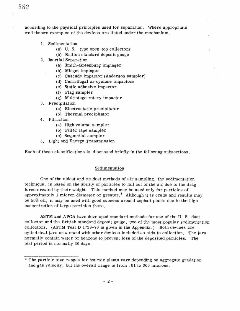
The standard wet impingers, such as the Smith-Greenburg and the: Midget (Figure 1) have efficiencies of virtually 100% down to one micron when operated at the proper gas flow rate of 1o 0 CFM for the Smith-Greenbu-rg and 10 CFM for the Midget. A vacuum pump is used to bubble the a•r through the liquid,-normally water or alcohol, contained in the impingero The suspended particles are required to make sharp direction change in order for the gas to exit which catches the particles and suspends them in the liquid. Analysis is sometimes difficult due to the dissolution of some particles in the liquid° These devices are the main instrument used for the measurement of gaseous concentrations and are not normally used to measure particulates as large as those found in the area of an asphalt plant.
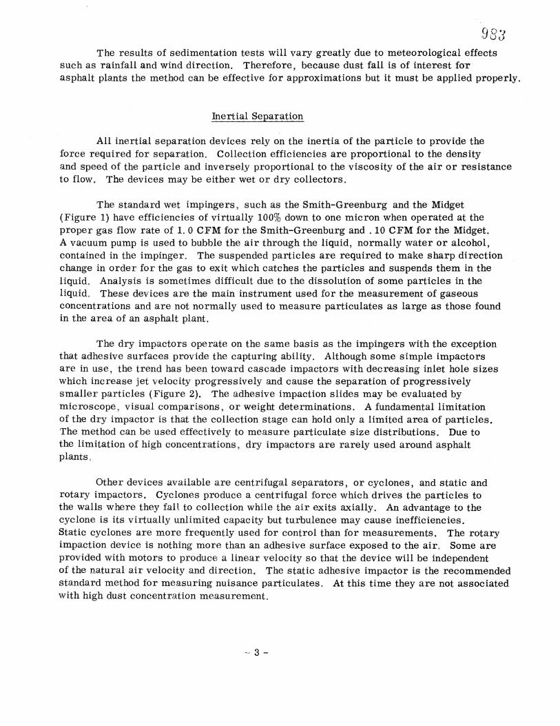
The dry impactors operate on the same basis as the impingers with the. exception that adhesive surfaces provide the capturing abilityo Although some simple impactors are in use, the trend has been toward cascade impactors with decreasing inlet hole sizes which increase jet velocity progressively and cause the separation of progressively smaller particles (Figure 2). The adhesive impaction slides may be evaluated by microscope• visual compar[sons• or weight determinations. A fundamental limitation of the dry impactor is that the collection stage can hold only a limited area of particles. The method can be used effectively to measure particulate size distributions. Due to the limitation of high concentrations• dry impactors are rarely used around asphalt plants°
Other devices available are centrifugal separators, or cyclones, and static and rotary impactors. Cyclones produce a centrifugal force which drives the particles to the. walls where they fair to collection while the air exits axially. An advantage to the cyclone is its virtually unlimited capacity but turbulence: may cause inefficiencies. Static cyclones are more frequently used for control than for measurements. The rotary impaction device is nothing more than an adhesive surface exposed to the air. Some are provided with-motors to produce a linear velocity so that the device will be independent of the natural air velocity and direction. The static adhesive impactor is the recommended standard method formeasuring nuisance particulates. At this time they are not associated with high dust concentration measurement°
Smith- Greenburg Midget
Figure 1. Two types of wet impingers.
Inlet
M=cr
•es -• Out et !
Figure 2. A common type of cascade impactor.
-4-
Precipitation.
Two types of precipitation devices are available: electrostatic and thermal. The electrostatic precipitator, well-known as a control device, removes particles from the gas stream by transferring a charge to the particles, which causes them to be collected on an oppositely charged surface. The efficiency is 100% for 01- 10 micron particles Until the precipitator reaches capacity. Disadvantages are its high cost, a possible explosion hazard in the presence of some gases, and the sophistication of the equipment that may cause problems when maintenance is required. Analysis can be done chemically, by weight, visually, or in advanced precipitators by microscopic examination.
Thermal precipitators, although not completely, understood, operate on the principle that in the presence of a .temperature gradient small particles will migrate to a region of lower temperature whe re they a•:e collected on an adhesive surface. Although the efficiency is nearly 100% over the particlesize range of. 001-100 microns a restricted flow rate of 5 to 10 cubic centimeters per minute is necessary and this requirement has restricted their use.
Filtration
Filtration has become the most widely used measurement technique in ambient air. Any particle size desired can be obtained. The different mechanisms of i°iltration are complex, and volumes have been written on the subject. Let it•suffice to say that the efficiency lor a particular distribution will increase with an increased retention size (smaller opening) of the filter, but the pressure drop required to maintain a given flow rate will also increase. Therefore, the filter materiat may be used at high flow rates for short periods of time or at low flow rates fo{• longer. times, depending on the desired results. It should be stressed that for any filtration technique, the composition, retention capability, and strength of the material must be carefully chosen in order for results to be representative. Depending on the media used, evaluation can be made visually,microscpp__tp_al•ly, or by light scattering, but most filters lend themselves easily to weight evaluations.
The high volume sampler is the m ost widely used measurement device for routine field sampling. It is used by the state of Virginia for community and industrial ambient air quality studies andis the recommended device for checking compliance with ambient air standards. It uses relatively large volumes of air, 30-60 cabic feet per minute. It has a short sample period, 24 hrs., and results can easily be obtained by we ighing.
The sampler is relatively compact, rugged, and durable. It includes a filter, a vacuum pump, and a brace equipped with a weather shield. The shield is also designed to minimize variations in air flow due to fluctuating wind velocities. A disadvantage of the shield is that large particles cannot reach the filter due to the tortuous path and no particle above about 50 microns can be-expected to be filtered.
The automatic filter tape sampler includes a mechanism which allows a section of filter to be exposed for only a certain .period of time, after which a new section is exposed. This is a good method for determining time-related fluctuations in particulate emissions. Analysis is strictly visual or by light transmission and quantitative results are difficult to obtain.
Light and Energy Transmission.
Use of the light scattering principle is the major research objective in particulate concentration determination. The advantage of the light energy transmission method is that the time required is short and for some devices analysis may be continuous.
Although some devices have been manufactured for field use (aerosol photometers, sun photometers, integrating nephelometers), the concept is not generally accepted as an accurate method of analysis. The devices manufactured are basically cumbersome, delicate, and expensive, but advances are expected that will permit continuous read-outs for measuring ambient air. A few devices of this type are used in stack sampling.
SAMPLING FREQUENCY
Although this paper does not deal with sampling locations and schedules, a few words must be said on these subjects since they are very important considerations for meaningful results. The determination of the sampling locations and number of sampling stations is a complex problem, but by using common sense and by being aware of the factors-which may influence the results, one can arrive at fairly good answers to these questions. In order for the sample to be representative of the air in the area, the meteorology, topography, and location of the outside sources must be considered.
Two main factors influence the frequency and time of sampling. Individual sampling periods should be short enough to define the cyclic emission levels while long enough to obtain a valid sample. The expected concentrations must be considered with the measurement method capacity and the analysis procedure. The time should be of sufficient duration that the sample will be measurable without s ignificant error.
-6-
SOURCE SAMPLING
Source sampling refers to the methods of sampling a particular source of a•r pollution. The purpose of source sampling is to determine the need. for control, the degree of compliance with existing codes, or the acceptance and efficiency of new equipment. The two source sampling methods best suited for use at hot mix plants are the visual smoke chart (R[nglemann chart) and stack sampling. They are-not similar and w•ll be discussed separately.
R inglemann C hart and Equivalent Op.a.c ity
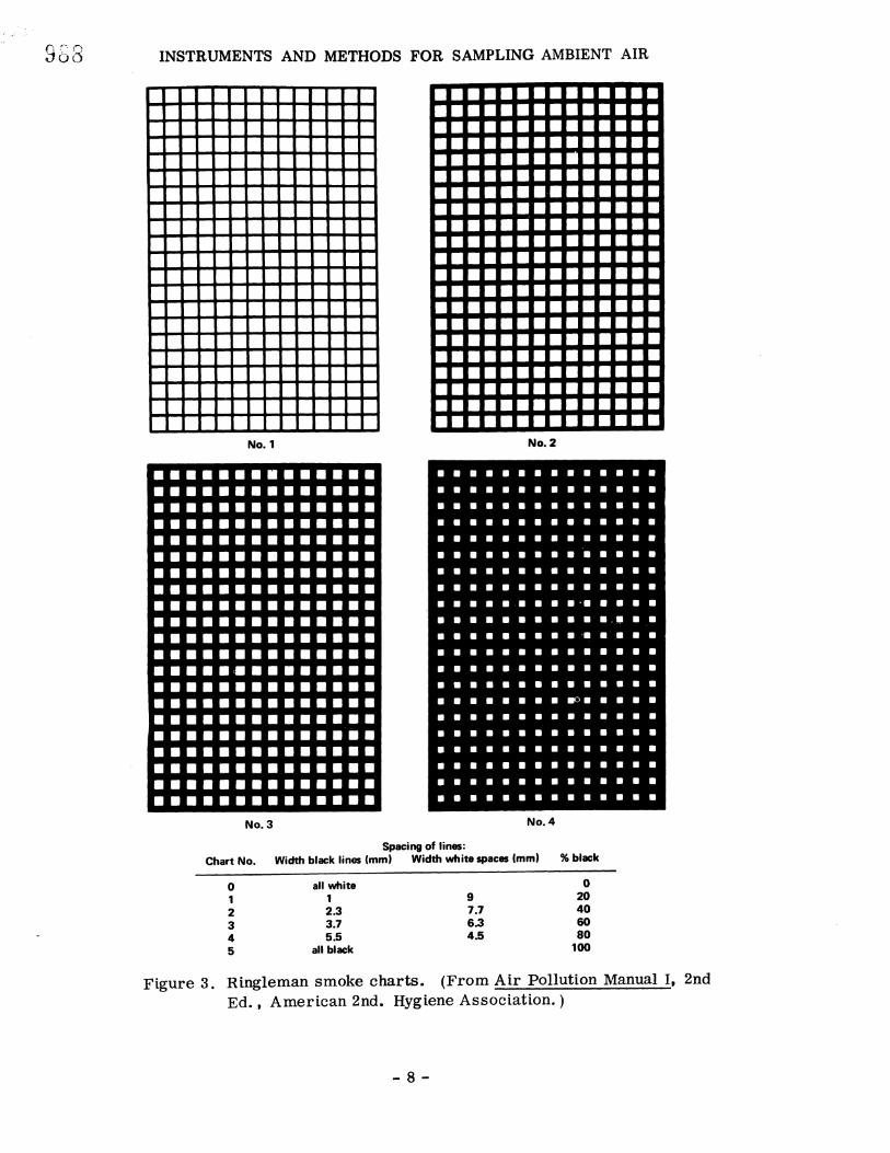
The R[nglemann chart dates back to 1898 and was devised for the evaluation of black smoke plumes. The method is based on a visual comparison of the plume with four cross-hatched charts. The charts, numbered 1-4, have progressively wider black lines so that each chart is supposed to be equivalent to a percentage .of blackness (see Figure 3). Equivalent opacity charts have been developed for white plt•mes using transparent plastic blocks containing industrial diamond particles of different light transmittance, but their application has been restricted to the California area.
Both these visual techniques have been severely cr[t[z[zed. The controversy concerning the methods •s whether or not allowances are necessary for the many variables involved. Many experts •eel that the results of a visual evaluation depend not only on the concentration of particulates; but on their size and surface properties, the diameter of the stack, plume velocity, many meteorological variables, plume illumination with the background, and the position of the observer with respect to the sun and plume. Despite all these variables, evaluations by trained observers have been held legally binding. The method is used almost everywhere in the country, mainly because of its simplicity.
Stack Sampl
In contrast to the simple visual method, stack sampling is very complex. Basically the method involves the use of a probe and vacuum pump to sample a gas stream as •t moves thro•gh the exhaust stack. This •techn[que normally involves minor modification of the stack to get the probe into the gas stream. Stack sampling is used in sampling for gaseous as well as particulate emissions. A collection device is included somewhere in the train. There may be more than one kind of collection device because a wide range of p a r t c 1 e sizes are expected, and there may be more than one of a particular type of collector, normally used to increase efficiency. The collecti.on devices used are the same type that are used for ambient collection, and their selection is based on desired results. There can be many combinations and the results will vary, not only with the types of collectors used but with their order in the sampling train. Two of the sampling trains accepted by the State of Virginia Air Pollution Control Board will be mentioned and discussed.
-7-
INSTRUMENTS AND METHODS FOR SAMPLING AMBIENT AIR
No. No. 2
No. 3 No. 4
Spacing of lines: Chart No. Width black lines (mm) Width white spaces (mm) % black
0 all white 0 9 20
2 2.3 7.7 40 3 3.7 6.3 60 4 5.5 4.5 80 5 all black 100
Figure 3. Ringleman smoke charts. (From Air Pollution Manual I, 2nd
Ed., American 2nd. Hygiene Association.
-8-
E PA Train
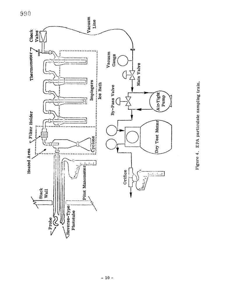
A diagram of the Environmental Protection Agency's sampling train is shown in Figure 4. The d[sttngu[shing characteristics are the heated area for particulate collection which encompasses cyclone and a filter and the iced area with [mpingers for the collection of condensible materials, including water vapor. The heated area is used to sample the gas at approximately the same temperature as the stack and is the main point of controversy concerning this method. Other methods allow the gas to cool before sampling. The main difference will be the measurement of condensible vapors that are considered particulates. Because of this difference, results obtained with one method may not be compared with results from another.
The relative positions of the cyclone, filter, and [mpingers tn the EPA train differ from the ASME train, yet to be discussed. The main collection device in the E:PA method is a filter that restricts flow by increasing the pressure drop across the train. Vartat[ons tn flow must be accounted for tn the analysis.
ASME Train
The American Society of Mechanical Engineers has a recommended train and procedure for the collection of dust in a gas stream. The ASME method ts quite s im[lar to the EPA method with the followtng exceptions. As previously mentioned, the gas stream [s allowed to cool before particulate collection. The main collection devices are impingers followed by a thimble filter. Because the [mp[ngers collect up to 95% of the part[culates, and the pressure drop across an
tmptnger rematns relattvely constant, the gas flow through the trai•n will not vary with the weight of the particulates collected. Normally a cyclone is not used as a
prtmary collector and no condenser is included.
General Sampltn• Method
once the sample train has been selected, definite ground rules for sampltng are used to account for the other variables. The sequence of the method is:
lo Locate pos[t•on in stack for sampling and determine number of samples needed.
2. Obtain velocity profile for stack at point of measurement.
3. Determine • stack velocities are continuous or cyclic.
4. If cycl[c, determine sampling schedule.
10-
5. Determine average molecular weight of gas using Orsat analyzer(C2, CO2, N)o
6. Proceed with sampling.
7. Analyze samples.
Locating the positi.on for stack sampling is of utmost importance. Although rigid guidelines exist, the position selected is usually a compromise due to the convenience or unavailability of an ideal location. The ideal location should be in a vertical section with at least 8 stack diameters in. length between the sampling point and any restriction, bend, or baffles. Verticle flow is advantageous over horizontal flow because it minimizes gravitational effects that may cause dust stratification. The straight section i.s needed to minimize turbulence• but if it can be assured that complete mixing is attai.ned because of extreme turbulence, this condition is desi.rable and can be used.
The number of sampling points across the duct depend on the cross sectional area and the expected velocity proi°•le. If the profile is relatively constant• then relati.vely i•ew sampling points are necessary. For round ducts, points are normally located on perpendicular diameters at equal areas from the center of the duct. The velocity profile is then obtained at these points by using a Pitot tube and an inclined manometer. If the veloci.ty profile changes drastically with time the procedure for sampling becomes complex and will not be covered here.
If the profi.le •s constant• then a calculati,on for veloc•t• needed through the train •s made in order to reach an •.sok•net•c cond[t[ono The [sok•net[c condition, parti•cularly •mportant in parti•culate measurement• is a condition in wh[eh the velocity [.n the nozzle •s equal to the velocity outside the nozzle in the stack, Although there are devices to ensure an [sok[neti•c state to assure the [sok[net[c condition within the 20% allowed by EPA, a calculation may be made after the velocity in the stack is known. If this parameter i•s disregarded in sampl[ng• the results may be off by 50% or more°
Once the desired flow rate at each sample point •s known• a manual value •s used to maintai•n the proper flow rate for each sample po[nto Each point is sampled for a gi•ven ti•me and the accumulati•on i°rom all points is grossed together as one result. Results normally reported are emission rate i•n pounds per standard cubic i•eet of gas• emi•ss•on mass rate i.n pounds per hour, and emission process rate •n pounds emission per ton processed.
STATE STANDARDS
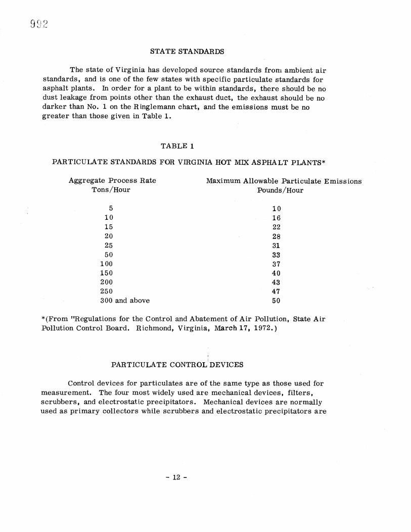
The state of Virginia has developed source standards from ambient air standards, and is one of the few states with specific particulate standards for asphalt plants. In order for a plant to be within standards, there should be no dust leakage from points other than the exhaust duct, the exhaust should be no darker than No. i on the Ringlemann chart, -and the emissions must be no greater than those given tn Table 1.
TABLE 1
PARTICULATE STANDARDS FOR VIRGINIA HOT MIX ASPHALT PLANTS*
Aggregate Process Rate Tons/Hour
Maximum Allowable Particulate Emissions Pounds/Hour
5 10 10 16 15 22 20 28 25 31 50 33
100 37 150 40 200 43 250 47 300 and above 50
*(From."Regulat[ons for the Control and Abatement of Air Pollution, State Air Pollution Control Board. Richmond, Virginia, March. 17, 1972.)
PARTICULATE CONTROL DEVICES
Control devices for particulates are of the same type as those used for measurement. The four most widely used are mechanical devices, filters, scrubbers, and electrostatic precipitators. Mechanical devices are normally used as primary collectors while scrubbers and electrostatic precipitators are
12-
primarily used as secondary or backup collecticin•devices. Due to the flexibility
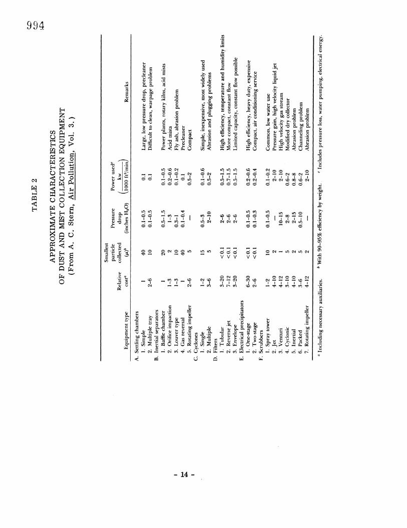
they allow in the size of the particulates retained, filtei•s may be used as either primary devices or as secondary collectors. The s.eleetton of collectors or series of eolleetors ts based upon cost and desired results. As a rule the pressure drop through two devices in series is much greater than for just one device, but the primary device will reduce the load of particulates to one which the secondary collector can handle easily. Table 2 summarizes the characteristics of particulate control devices.
Mechanical Collectors
Except for the multistage cyclone apparatus, mechanical collectors are of low efficiency and are used as precleaners or primarly collector.s. Examples of mechanical devices which are based on gravitional sedimentation are the baffle chamber, settling chamber, skimming chamber, and the louver-type collector. These devices are used where large particles are an extreme problem':" The smallest particle that will normally be removed is about 40 microns.
The most widely used mechanical collectors are the cyclone and multiple cyclone devices The cyclone is a widely used primary collector that collects 95% of the particles above 40 microns and 80% of the particles between 15-50 microns. In general, for a random distribution of particles, an efficiency of 75-80% may be expected. The efficiency of particulate removal increases with an increase in particle diameter or tangential velocity, or a decrease in cyclone diameter or gas velocity.•. For this reason small multiple cyclones (cyclones in parallel) have much greater efficiencies with high pressure drops.
Because the cyclones have no moving parts they are trouble free.. They are low in cost and can be built from materials to withstand chemical deterioration associated with some exhaust gases. The pressure drops resulting from their use
are considered medium compared to those encountered with other devices.
About the only problems with a cyclone device are erosion and fouling. Erosion is a problem with hard particles, high dust loadings, and high velocities. The areas most subject to erosion damage are those at welds, so these should be kept to a minimum. Fouling is a term that includes pluggage of the dust outlets or a buildup of material on the cyclone wall. Although this condition does not cause damage to the cyclone, it doe•decrease efficiency and increase the pressure drop. The main causes of fouling are condensation and fine dust particles. Routine clean outs can prevent the problem from becoming serious. It should be noted that fouling is a much more severe problem with the multiple cyclone due to its smaller diameters• clean out is also much more difficult.
13-
VVV VV
/ / / /
:1.4-
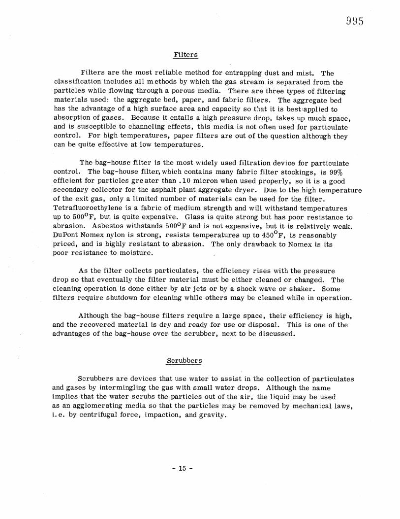
Filters
Filters are the most reliable method for entrapping dust and mist. The classification includes all methods by which the gas stream is separated from the particles while flowing through a porous media. There are three types of filtering materials used: the aggregate bed, paper, and fabric filters. The aggregate bed has the advantage of a h•gh surface area and capacity so .t:•at it is best•appl[ed to absorption of gases. Because it entails a high pressure drop, takes up much space, and is susceptible to channeling effects, this media is not often used for particulate control. For high temperatures, paper filters are out of the question although they can be quite effective at low temperatures.
The bag-house filter is the most widely used filtration device for particulate control. The bag-house filter, which contains many fabric filter stockings, is 99% efficient for particles greater than .10 micron when used properly, so it is a good secondary collector for the:asphalt plant aggregate dryer. Due to the high temperature of the exit gas, only a limited number of materials can be used for the filter. Tetrafluoroethylene is a fabric of medium strength and will withstand temperatures up to 500°F, but is quite expensive. Glass is quite strong but has poor resistance to abrasion. Asbestos w•thstands 500°F and is not expensive, but it is relatively weak. DuPont Nomex nylon is strong, resists temperatures up to 450°F, is reasonably priced, and is highly resistant to abrasion. The only drawback to Nomex is its poor resistance to moisture.
As the filter collects particulates, the efficiency rises with the pressure drop so that eventually the filter material must be either cleaned or changed. The cleaning operation is done either by air jets or by a shock wave or shaker. Some filters require shutdown for cleaning while others may be cleaned while in operation.
Although the bag-house filters require a large space, their efficiency is high, and the recovered material is dry and ready for use or disposal. This is one of the advantages of the bag-house over the scrubber, next to be discussed.
Scrubbers
Scrubbers are devices tha•t use water to assist in the collection of particulates and gases by intermingling the gas with small water drops. Although the name implies that the water scrubs the particles out of the air, the liquid may be used as an agglomerating media so that the particles may be removed by mechanical laws, [. e. by centrifugal force, impact•on, and gravity.
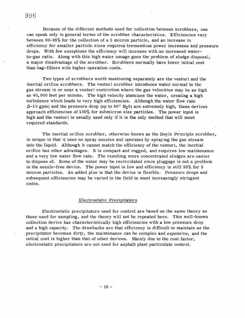
Because of the different methods used for collection between scrubbers, one
can speak only in general terms of the scrubber characteristics. Eff[cienc[es vary between 90-95% for the collection of a 5 micron particle, and an increase in efficiency for smaller particle s[ze.s requires tremendous power increases and pressure drops. With few exceptions the efficiency will increase with an increased water- to-gas ratio. Along with this high water usuage goes the problem of sludge disposal, a major disadvantage of the scrubber. Scrubbers normally have lower initial cost than bag-filters with higher operation costs.
Two types of scrubbers worth mentioning separately are the ventur[ and the inertial or[rice scrubbers. The ventur[ scrubber introduces water normal to the gas stream in or near a ventur[ restriction where the gas velocities may be as high as 40,000 feet per minute. The high velocity atomizes the water, creating • high turbulence which leads to very high effic[enc[es. Although the water flow rate (•5-i0 gpm) and the pressure drop (up to 80" H20) are extremely high, these devices approach eff[c[enc[es of 100% for subm[cron size particles. The power input is high and the ventur[ is usually used only if it is the only method that will meet required standards.
The inertial orifice scrubber, otherwise known as the Doyle Principle scrubber, is unique in that it uses no spray nozzles and operates by spraying the gas stream into the liquid. Although it cannot match the efficiency of the ventur[, the inertial or[rice has other advantages. It is compact and rugged., and r.equ[res low maintenance and a very low water flow rate. The resulting more concentrated sludges are easier to dispose of. Some of the water may be recirculated since pluggage is not a problem in the nozzle-free device. The power input is low and efficiency is still 95% for 5 micron part[cl-es. An added plus is that-the device is flexible Pressure drops and subsequent effic[enc[es may be varied in the field to meet increasingly stringent codes.
Electrostatic Precipitators
Electrostatic precipitators used for control are based on the same theory as
those used for sampling, and the theory will not be repeated here. This well-known collection device has characteristically high ef•[cienc[es with a low pressure drop and a high capacity. The drawbacks are that efficiency is difficult to maintain as the precipitator becomes dirty, the mai_ntenance can be complex and expensive, and the initial cost is higher than that of other devices. Mainly due to the cost factor, electrostatic precipitators are not used for asphalt plant particulate control.
16-
BIB LIOGR,A PHY
American Industrial Hygiene Association, Air Pollution Manual, 2 Volumes, Detroit, Michigan, 1970.
ASME ATC 27-57, American Society of Mechanical Engineers, "Determining Dust Concentrations in a Gas Stream, Power Test Code, " 1957.
" Louisiana Burt, W T and B J. Gueho "Air Pollution from Hot Mix Plants, Department of Highways, October 1970.
Epps, J. A., B. M. Galloway, and R. L. Terrel, "Pollution--Sources and Solutions tn Bttuminous Construction, " paper presented at 1972 meeting of Highway Research Board.
5. How Bag Collectors Work, Roads and Streets, November 1971, p. 74.
Morrow, No L., R. S. Brief, and R. R. Bertrand, "Sampling and Analyzing Air Pollution Sources," Chemical Engineering• January 24• 1972•pp. 84-98.
National Asphalt Pavement Association, Environmental Pollution Control at Hot Mix Asphalt Plants, Information Series 27.
National Asphalt Pavement Association, Guide for Air Pollution Control of Hot Mix Asphalt Plants, Information Series 17.
Nothing Clear on the Air Pollution Control Front, Roads and Streets, November 1972, pp. 103-105.
Sargent, Go D., "Gas/Solids Separations," Chemical Engineering, February 15, 1972, pp. 11-22.
11. Stern, A. Co, Air Pollution, 3 Volumes, New York, 1968.
U. S. Department of Health, Education and Welfare, Air Quality Criteria for Particulate Matter, Washington, D. C., 1969.
Wallings, J. C.• "Pollution Control Systems for Asphalt Plants, " Roads and Streets, May 1971, pp. i14•i18o

APPENDICES

American National Standard 2116.1 1970 American National Standards Institute
Standard Method for COLLECTION AND ANALYSIS OF DUSTFALL (Settleable Particulates);
This Standard is issued under the fixed designation D 1739; the number immediately following the designation indicates the year of original adoption or, in the case of revision, the year of last revision. A number in parentheses indicates the year of last reapproval.
1.1 This method covers a procedure for the field collection of particulates settling from atmosphere, and for preliminary characteriza- tion of the sample matter. As further analyti- cal methods are developed for components these will be added to this method.
2. Sammary of Method 2.1 Open-top collectors of a specified size
and shape are located carefully outdoors to provide particulate samples that are represen- tative of the area being studied. Collected material is taken to the laboratory in a closed container for weighing and analysis. Proce- dures are described for the determination of pH, total weight of settleable particulates, total water and benzene solubles, and total combustible and noncombustible matter.
3. Definitims 3.1 settleable particulates--for this method,
any particles, liquid or solid, small enough to pass through a l-mm screen and large enough to settle in the collector.
3.2 For definitions of other terms used in this method, refer to ASTM Definitions D 1356, Terms Relating to Atmospheric Sam- pling and Analysis? 4. Interferences
4.1 Care must be taken to avoid matter from trees, bird droppings, and other such deposits. Loss of material from the collector by action of wind must be prevented. If a glass collector is used, protection against breakage by freezing of liquid sample should be provided when necessary. The sample
collector should be protected from vandalism. The criteria for selecting the sampling site (see 6.5) must be adhered to.
5. Apparatus and Materials 5.1 Collector--The collector shall be an
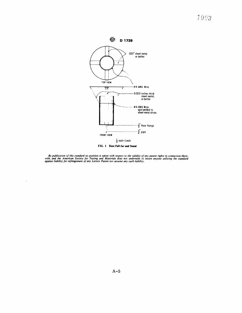
open-topped cylinder with vertical sides and flat bottom. Cylinders shall be not less than 6 in. in diameter. Height of the cylinder shall be from two to three times the diameter dimen- sion. Collectors may be made of glass, plastic, or stainless steel. (Glass, although permitted, is not preferable because of its fragility.) A holder shall be provided to secure and ensure safe positioning of the collector. The top of the collector should be at least 3 in. above any part of the holder. The holder should not in- terfere with operation of the collector in any way. A bird ring shall be provided on the holder (see Fig. 1).
No•'•. l--No definitive aerodynamic studies have been. made of collector design, so the above specifi- cations cannot assure optimum collection. Pending such studies, any network of stations within which comparisons are to be made should use identical collectors. If especially high winds characterize the study area, frequent inspection will reveal obvious reentrainment of dust.
5.2 Sieue, No. 18 (1 mm) (chemically inert), conforming to the requirements of ASTM Specification El 1, for Wire-Cloth Sieves for Testing Purposes.
5.3 Ouen, thermostatically controlled.
This method is under the iurisdiction of ASTM Com- mittee D-22 on Sampling and Analysis of Atmospheres. A list of members may be found in the ASTM Yearbook.
Current edition effective Oct. 15, 1970. Originally is- sued 1960. Replaces D 1739 62 (1967).
Annual Book of ASTM Standards, Part 23. Annual Book of ASTM Standards, Part 10.
5.4 Filter Paper, soft, open, rapid filtering. 5.5 Soxhlet Extraction Apparatus or other
efficient extractor. 5.6 Water, conforming to ASTM Specifica-
tions D 1193, for Reagent Water. 5.7 Antifreeze--lsopropyl alcohol reagent
grade. NOTE 2nEthyl alcohol may be used, provided
that the collector is policed with efficient frequency to ensure that it is not permitted to dry out and that the correct concentration of antifreeze is .main- tained during the sampling period. In areas where organic matter is not being studied ethylene glycol may be used.
6. Sampling 6.1 General Sampling PrinciplesNAppli
cation of this method shall be guided by ASTM Recommended Practice D 1357, for Planning the Sampling of the Atmosphere.
6.2 Preparation of the Collector: 6.2.1 Thoroughly rinse the collector. Place
distilled water in the collector so that the level stands at one half the .collector depth when the test is started. In cold weather mix a suffi- cient volume of antifreeze to prevent freezing with the water. In warm weather add suffi- cient copper sulfate as an algicide to give 15 rag/liter if the collector fills. Under the latter condition copper cannot be determined.
6.2.2 Collector liquid should be kept at a reasonable level during the testing period (at least in. of water at all times).
6.3 Sampling TimemA sampling period shall be calendar month corrected to 30 days. Allowance of =i= 2 days is permissible for setting out or collecting sampling jars, or both.
6.4 Handling Collected SamplemNo at- tempt shall be made to remove collected par- ticulate sample from the collector at the field site. Collectors shall be covered and taken to the laboratory for analysis of the contents.
6.5 Selection of Sampling Site (2,3)4--The following specific recommendations shall be used as a guide in the selection of a site. If conditions do not permit application of these recommendations, note shall be made of this.
6.5.1 The sampling station shall have a free exposure so that the sample is collected by gravity settling only. It must be free from undue local sources of pollution and free from interference from buildings or other higher objects or structures. Accessibility and secu-
D 1739
rity (freedom from tampering) are major con- siderations in the selection of a site.
6.5.2 The top of the settleable particulates container shall be a minimum of 8 ft and a maximum of 50 ft above the ground. It shall be 4 ft above any other surface, such as a roof. Higher objects, such as parapets, signs, pent- houses, and the like, shall not be more than 30 deg from the horizontal, as measured in 6.5.4.
NOTE 3--Available evidence suggests, but does not prove, that the measured particulates will vary markedly over the height limits of 8 to 50 ft. It is recommended, therefore that every attempt be made to keep collector heights as constant a• possi- ble within a given network.
6.5.3 Public buildings such as schools, fire stations, and libraries, are most favorable to public agencies because of their accessibility and security.
6.5.4 Take care to avoid undue influence from one chimney, (for example, the chimney on the building of the sampling station). Whenever possible, the sampling container shall be set more than ten stack lengths from an operating stack and upwind from the pre- vailing wind.
6.5.5 When higher buildings in the imme- diate vicinity cannot be avoided, the top of any building shall 'be not more than 30 deg above a sampling point. That is, a line drawn from the sampling jar to the nearest edge of the highest point on any building shall form not more than 30 deg angle with the horizon- tal.
6.5.6 Sampling shall not be done where there is a possibility of contamination by motor traffic.
6.6 Number of Sampling Stations (l)--For each area or zone to be tested, a minimum of four sampling stations shall be provided. An orderly spacing of the stations shall be made so that they are approximately equally distant from each other and from boundaries of the area. Record vertical distance from collector to ground for each sampling station.
6.7 Auxiliary information--Weather data, including wind velocity and direction, rainfall, snowfall and barometric readings, air pollu- tion information, and other information of interest and value should be recorded during
The boldface numbers in parentheses refer to a list of references at the end of this method.
the sampling period.
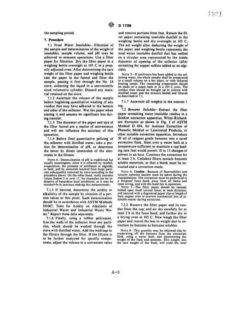
7. Procedure
7.1 Total Water Insolubles--Filtration of the sample and determination of the weight of insolubles, sample volume, and pH may be achieved in common operations. Use a filter paper for filtration. Dry the filter paper in a weighing bottle overnight at 105 C in a prop- erly adjusted oven. After determining the tare weight of the filter paper and weighing bottle seat the paper in the funnel and filter the sample, passing it first through the No. 18 sieve, collecting the liquid in a conveniently sized volumetric cylinder. Discard any mate- rial retained on the sieve.
7.1.2 Ascertain the volume of the sample before beginning quantitative washing of any residue that may have adhered to the bottom and sides of the collector. Wet the paper when seating it and assume no significant loss dur- ing transfer.
7.1.3 The diameter of the paper and size of the filter funnel are a matter of convenience and will not influence the accuracy of this operation.
7.1.4 Before final quantitative policing of the collector with distilled water, take a por- tion for determination of pH, or determine the latter by direct immersion of the elec- trodes in the filtrate.
NOTE 4--Determination of pH is traditional but usually meaningless, since it is affected by rainfall, evaporation, the _presence of antifreeze or algicide., or both, and by materials leached from large pam- cles subsequeltly removed by sieve according to the procedure above. On the other hand, really extreme values (below 3 or over 11, for example) can be in- dicative of hazardous local conditions, so it may be worthwhile to continue making this measurement.
7.1.5 If desired, determine the acidity or alkalinity of the sample by titration of a por- tion taken at this point. Such determination should be in accordance with ASTM Methods D1067, Tests for Acidity on Alkalinity of Industrial Water and Industrial Waste Wa- ter? Report these data separately.
7.1.6 Finally, using a rubber policeman, free the walls of the collector from any parti- cles, which should be washed through the sieve with distilled water. Add the washings to the filtrate through the filter. If the filtrate is to be further analyzed for specific compo- nents, adjust the volume to a convenient value
D 1739
and remove portions from that. Return the fil- ter paper containing insoluble dustfall to the weighing bottle and dry overnight at 10:5 C. The net weight after deducting the weight of the paper and weighing bottle represents the total water insoluble dustfall that has settled on a circular area represented by the inside diameter of opening of the collector (after correcting for copper sulfate added as an algi- cide).
NOTE 5--1f antifreeze has been added to the col- lecting water, the whole sample shall be evaporated to a small volume on a hot plate, or with infrared heating lamps. The remaining evaporation should be made on a steam bath or in a 105 C oven. The residue then should be brought up to volume with distilled water and the mixture boiled and filtered as described in 7.1.
7.1.7 Ascertain all weights to the nearest mg.
7.2 Benzene Solubles--Extract the filter paper containing water insoluble residue in a Soxhlet extraction apparatus, Wiley-Richard- son Extractor as shown in Fig. 2 of ASTM Method D 494, for Acetone Extraction of Phenolic Molded or Laminated Products, or other suitable extraction apparatus. Introduce 50 ml of reagent grade benzene into a tared extraction flask. Heat over a water bath at a temperature sufficient to maintain a cup load- ing rate that would permit 10 to. 15 changes of solvent in an hour. Continue the extraction for at least 2 h. Cellulose filters contain benzene soluble materials, so that a blank must be ex- tracted and a correction made.
NOTE 6: Caution--Because of flammability and toxicity extreme caution must be taken during the manipulations. The extraction must be performed in a fireproof fume hood, away from all flame and open wiring, and with the hood fan in operation.
NOTE 7--The filter paper should be opened, folded upon itself several times in each direction, and secured with a degreased paper clip or length of bare copper wire to prevent mechanical loss of in- soluble matter during extraction.
7.2.2 Remove the filter paper and its resi- due from the cup, and air dry carefully for at least 2 h in the fume hood, and further dry in a drying oven at 105 C. Now weigh the filter paper and record the loss in weight due to ex- traction by benzene as benzene solubles.
NOTE 8mThis quantity may be obtained also by evaporating off the benzene from the extraction flask, using a water bath, and determining the weight of the flask and contents. This weight, less the tare weight of the flask, will yield the total
weight of benzene solubles. The eluted matter is• the flask may be analyzed further after evaporation of the benzene.
7.3 Combustibles and Volatile Particulates Other than Benzene Solubles--Ash the filter paper in a tared crucible and report the loss in weight as: "Combustibles and volatile particu. lates other than benzene soluble."
7.3.1 If further analyses for specific materi- als are desired, ignite an aliquot of the filter paper and determine "combustibles and vola- tile particulates other than benzene solubles" from this as in 7.3.1. Use the remaining por- tion for further analyses.
7.3.2 Take the aliquot as follows: Open and cut the filter paper into eight equal radial segments. Use four alternate segments in this determination, and reserve the other four for the further analyses.
7.4 Insoluble Matter--Report the net resi- due after deducting the weight of the crucible in the above step as "inorganic insoluble par- ticulates." Retain this for further analysis.
7.5 Total Water Soluble--Make up the water soluble filtrate to a convenient definite volume in a volumetric flask. Take a suitable aliquot to determine soluble salts. Transfer by means of a pipet to a weighed borosilicate evaporation dish as described in ASTM Method D 381, Existent Gum in Fuels by Jet Evaporation? If fluorides or caustic materials are suspected to be present, conduct the evap- oration, in a platinum dish of convenient size. Conduct the evaporation slowly on a hot plate, or under an infrared heat lamp, until the vol- ume is about 25 mi. Complete the evaporation on a steam bath or a thermoregulated hot plate set at a temperature not greater than 99 C. When dry, heat the dish in a 105 C oven
D 1739
for a period of 2 h, cool in a desiccator, and weigh. Continue the drying procedure to con- stant weight.
7.5.1 Report the gain in weight of the evap- orating dish, adjusted for aliquot portion, and correct for any solids present in a distilled water blank as total water solubles.
7.6 Total lnorfanic Particulates--Report the combined weight of water insolubles and soluble matter corrected for any solids present in a distilled water blank as total inorganic matter.
7.7 Unit for Dam--Express settleable par- ticulates as "grams per square meter per month."
8. Caleulatlo. 8.1 Calculate the settleable particulates, D,
in grams per square meter per month as fol- lows:
D-
where: D settleable particulates, g/m month, W,• total weight of settleable particulates
(sum of total insolubles and water solubles) (7.1 and 7.5), and
A• sampling area, m
Nm'e 9--Settleable particulates may be con- verted to tons per square mile per months by means of the following conversion units:
g- 1.1023 × 10 -e tons, and
m -.3.8608 × 10 -7 miles? 8.2 Express all other data in appropriate units, or as percentage of settleable particu- lates, D.
Annual Book of ASTM StandardJ, Part 17.
REFERENCES
(I) Meetham, A. R., Atmospheric Pollution: its Origin and Prevention, The Pergamon Press, London 3rd edition, 1964, Chapter I1: Meas- urements of Air Pollution.
(2) Nader J. S., "Dust Retention Efficiencies of Dustfall Collectors," Journal of the Air Poilu-
tion Central Association, JPCAA, Vol 8, 1958, pp. 35 to 38.
(3) Recommended Standard Methods for Continu- ing Dustfall Survey (APM-I, Revision 1), Jour- nal of Air Pollution Control Association, JPCAA, Voi 16, No. 7, 1966, pp. 372 to 377.
i•i•) D1739 "••• 4••
.020" sheet metaJ or better
TOP VIEW
\ • ,/ #4 AWG Wire '• 0.020 inches thick sheet metal, or better
•"•--- #4 AWG Wire
spot welded to sheet metal strips
-¼" floor flange ¼' pipe
FRONT VIEW
4 A- inch: inch
FIG. Dust Fall Jar and Stand
By publication of this standard no position is taken with respect to the validity of any patent rights in connection there. with, and the American Society for Testing and Materials does not undertake to insure anyone utilizing the standard against liability for infringement of any Letters Patent nor assume any such liability.