
Particle Adhesion Fundamentals and Bulk Powder Consolidation+
13
Particle Adhesion Fundamentals and Bulk Powder Consolidation+ Jiirgen Tomas The Otto-von-Guericke-University Magdeburg, Mechanical Process Engineering* Abstract The fundamentals of particulate solids consolidation and flow behaviour using a reasonable com- bination of particle and continuum mechanics are explained. By means of the model "stiff particles with soft contacts" the combined influence of elastic, plastic and viscoplastic repulsion in particle contacts is derived. Consequently, contact normal force displacement FN(hK) and adhesion force models FH(FN) are presented to describe the stationary, instantaneous and time consolidation behav- iour in particle contacts as well as in the bulk. On this particle mechanical basis, the stationary, instantaneous and time yield loci as well as uniaxial compressive strength O"c ( 0" 1 ), effective angle of internal friction tf>e( 0" 1 ), bulk density pb( 0"1) are derived and shown for a very cohesive sub-micron titania powder. Finally, these models in combination with accurate shear cell test results are used as constitutive functions for computer aided silo design for reliable flow and pressure calculations. 1. Introduction The well-known flow problems of cohesive particu- late solids in storage and transportation containers, conveyors or process apparatuses leads to bridging, channelling, oscillating mass flow rates and particle characteristics with feeding and dosing problems as well as undesired effects like widely spread residence time distribution, fertiliser time consolidation process or caking, chemical conversions, food deterioration and finally insufficient element and system reliability of solid processing plants. Taking into account this list of selected technical problems and hazards, it is really necessary to deal with the fundamentals of par- ticulate solids consolidation and flow behaviour, name- ly from using a reasonable combination of particle and continuum mechanics. 2. Particle Contact Constitutive Model The well-known failure hypotheses of Tresca, Cou- lomb-Mohr (3) and the yield locus concept of Jenike (1, 2) and Schwedes (4, 5) as well as the Warren- Spring-Equations (6) to (10) were specified from Molerus (11 to 14) by the cohesive steady-state flow criterion. The consolidation and non-rapid flow of fine and cohesive particulate solids (size d < 100 j.tm, flow * Universitatsplatz 2, D-39106 Magdeburg, Germany, Phone: ++49 391 67 18783, Fax: ++49 391 67 11160, e-mail: juergen. tomas@vst. uni-magde burg.de t Received: November 9, 2000 KONA No.18 (2000) or deformation rate v< 1 m/s, therefore shear stress Tv<p·v 2 /2""' 1 kPa, pressure cr""'0.1-100 kPa) was ex- plained by acting adhesion forces in particle contacts, Molerus (11). On principle, there are four essential mechanical deformation effects in particle surface contacts and their physical behaviour- influenced namely by me- chanical, optical and electromagnetic material charac- teristics of bulk phase- can be distinguished as follows: (1) reversible elastic (Hertz (15), Huber (16), Mindlin (17), Dahneke (19), DMT theory from Derjagin et al. (20) and JKR theory from Johnson et al. (21, 22), Thornton (27)) without deformation rate and consolidation time effects, valid for all particulate solids; (2) irreversible plastic (Krupp (18), Schubert (23), Molerus theory (11, 12), Maugis (26) and Thorn- ton (28) ), deformation rate and consolidation time invariant, e.g. mineral powders; (3) reversible viscoelastic (Hsuin (24) and Rumpf et al. (25) ), deformation rate and consolidation time variable, e.g. cut post-consumer waste particles; (4) irreversible viscoplastic (Rumpf et al. (25) ), defor- mation rate and consolidation time variable, e.g. fine particle fusion. If an external compressive normal force F N is acting on a soft contact of two isotropic, stiff. linear elastic, mono-disperse spherical particles the previous con- tact point is deformed to a contact area and the adhe- sion force between these two partners is increasing, see Fig. 1. 157
Transcript of Particle Adhesion Fundamentals and Bulk Powder Consolidation+
Particle Adhesion Fundamentals and Bulk Powder Consolidation+
Jiirgen Tomas The Otto-von-Guericke-University Magdeburg, Mechanical Process Engineering*
Abstract
The fundamentals of particulate solids consolidation and flow behaviour using a reasonable com
bination of particle and continuum mechanics are explained. By means of the model "stiff particles
with soft contacts" the combined influence of elastic, plastic and viscoplastic repulsion in particle contacts is derived. Consequently, contact normal force displacement FN(hK) and adhesion force models FH(FN) are presented to describe the stationary, instantaneous and time consolidation behav
iour in particle contacts as well as in the bulk. On this particle mechanical basis, the stationary, instantaneous and time yield loci as well as uniaxial compressive strength O"c ( 0"1), effective angle of
internal friction tf>e( 0"1), bulk density pb( 0"1) are derived and shown for a very cohesive sub-micron
titania powder. Finally, these models in combination with accurate shear cell test results are used as constitutive functions for computer aided silo design for reliable flow and pressure calculations.
1. Introduction
The well-known flow problems of cohesive particulate solids in storage and transportation containers, conveyors or process apparatuses leads to bridging, channelling, oscillating mass flow rates and particle characteristics with feeding and dosing problems as well as undesired effects like widely spread residence time distribution, fertiliser time consolidation process or caking, chemical conversions, food deterioration and finally insufficient element and system reliability of solid processing plants. Taking into account this list of selected technical problems and hazards, it is really necessary to deal with the fundamentals of particulate solids consolidation and flow behaviour, namely from using a reasonable combination of particle and continuum mechanics.
2. Particle Contact Constitutive Model
The well-known failure hypotheses of Tresca, Coulomb-Mohr (3) and the yield locus concept of Jenike (1, 2) and Schwedes (4, 5) as well as the WarrenSpring-Equations (6) to (10) were specified from Molerus (11 to 14) by the cohesive steady-state flow criterion. The consolidation and non-rapid flow of fine and cohesive particulate solids (size d < 100 j.tm, flow
* Universitatsplatz 2, D-39106 Magdeburg, Germany, Phone: ++49 391 67 18783, Fax: ++49 391 67 11160, e-mail: juergen. tomas@vst. uni-magde burg.de
t Received: November 9, 2000
KONA No.18 (2000)
or deformation rate v< 1 m/s, therefore shear stress Tv<p·v2/2""' 1 kPa, pressure cr""'0.1-100 kPa) was explained by acting adhesion forces in particle contacts, Molerus (11).
On principle, there are four essential mechanical deformation effects in particle surface contacts and their physical behaviour- influenced namely by mechanical, optical and electromagnetic material characteristics of bulk phase- can be distinguished as follows: (1) reversible elastic (Hertz (15), Huber (16), Mindlin
(17), Dahneke (19), DMT theory from Derjagin et al. (20) and JKR theory from Johnson et al. (21, 22), Thornton (27)) without deformation rate and consolidation time effects, valid for all particulate solids;
(2) irreversible plastic (Krupp (18), Schubert (23), Molerus theory (11, 12), Maugis (26) and Thornton (28) ), deformation rate and consolidation time invariant, e.g. mineral powders;
(3) reversible viscoelastic (Hsuin (24) and Rumpf et al. (25) ), deformation rate and consolidation time variable, e.g. cut post-consumer waste particles;
(4) irreversible viscoplastic (Rumpf et al. (25) ), deformation rate and consolidation time variable, e.g. fine particle fusion.
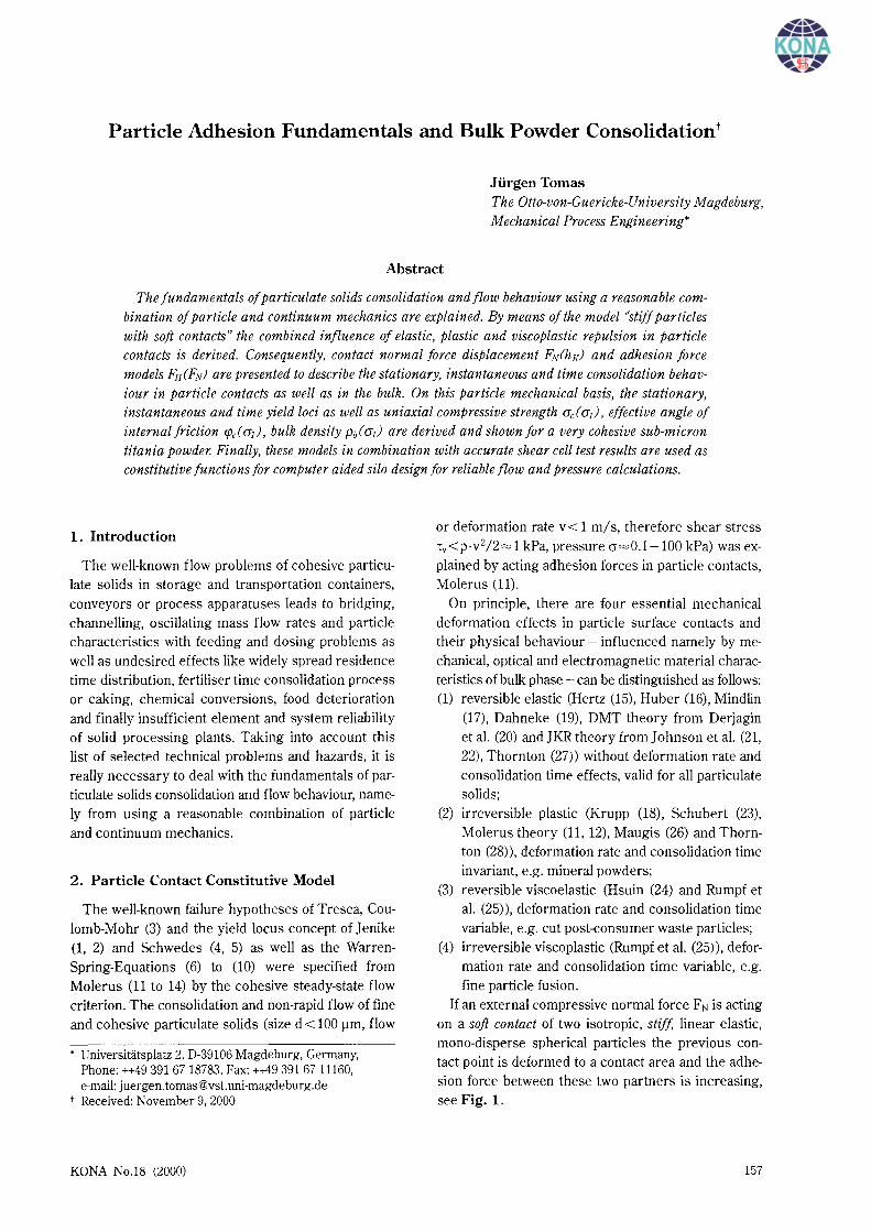
If an external compressive normal force F N is acting on a soft contact of two isotropic, stiff. linear elastic, mono-disperse spherical particles the previous contact point is deformed to a contact area and the adhesion force between these two partners is increasing, see Fig. 1.
157
a) contact approaching to a sphere-sphere-contact b) elastic contact deformation to a plate-plate-contact
____ _, __ Pmax<Pr
c) elastic-plastic contact deformation to a plate-plate-contact d) plate-plate-contact removing
;
,-
pressure distribution ..... _:- " with plastic yielding rK.pl rK.el.f
at Pmax=p,
Fig. 1 Particle contact approaching, elastic, elastic-plastic deformation and removing
First of all, Rumpf et al. (25) have developed a constitutive model approach for describing the linear increasing of adhesion force F H, mainly for plastic contact deformation:
( PVdW) PVdW FH= 1+-- ·FHo+--·FN
Pt Pt (1)
With another prerequisite and derivation Molerus (12) obtained an equivalent formula:
Pvdw F F FH = FHo+--· N = FHo+Kp· N PI
(2)
The adhesion force FHo without additional consolidation (FN=O) can be approached as a single spheresphere-contact, see Fig. la). This soft particle contact is flattening by the external normal force FN to a plateplate-contact, Fig. lc). The coefficient Kp describes a dimensionless ratio of attractive Van Der Waals pressure Pvdw for a plate-plate model to repulsive particle micro-hardness p1 (resistance against plastic deformation)
Kp = PVdW = CH,sls PI 6·n·a~=o·PI
(3)
158
and is to be called here as a plastic repulsion coefficient. The characteristic adhesion separation distance lies in a molecular scale (atomic centre to centre distance) and amounts to about a=aF=o=0.3-0.4 nm. It depends mainly on the properties of liquid-equivalent packed adsorbed layers and can be estimated for a molecular force equilibrium or interaction potential minimum -dU/da=F=O=Fattraction+Frepuision· The Hamaker constant solid-liquid-solid CH,sls ace. to Lifschitz theory is related to continuous media, dependent on their permittivities (dielectric constants) and refractive indices, see Israelachvili (29).
If the contact radius r is small compared with the particle size d, an elliptic pressure distribution Pe1(r) is found, see Hertz (15). Schubert (23) has combined the elastic and plastic contact strain expressed with the annular elastic Ae1 and circular plastic Ap1 contact area:
F PVdW H = FHo+ ·FN
pr(1 +2·Aei/(3·Ap0) (4)
Taking into account these Eqs.(l), (2), (4) as well as the model from Thornton (28) and superposition pro-
KONA No.18 (2000)
vided, the particle contact force equilibrium between attraction (-) and elastic as we11 as plastic repulsion or force response ( +)
~)=0= -FHo-Pvctw·1t·d-FN+Pt·1t·r~l rc
+2·1tJ Pel(r)·r dr (5)
delivers a very useful linear force displacement model for KA =con st. with the particle centre approach of both partners hK (32), Fig. 2:
(6)
Thus, the contact stiffness decreases with sma11er size especia11y for cohesive fine powders and nanoparticles, predominant plastic yielding behaviour provided (32):
(7)
25
But if we consider Eq.(9) a slightly nonlinear (progressively increasing) curve is obtained.
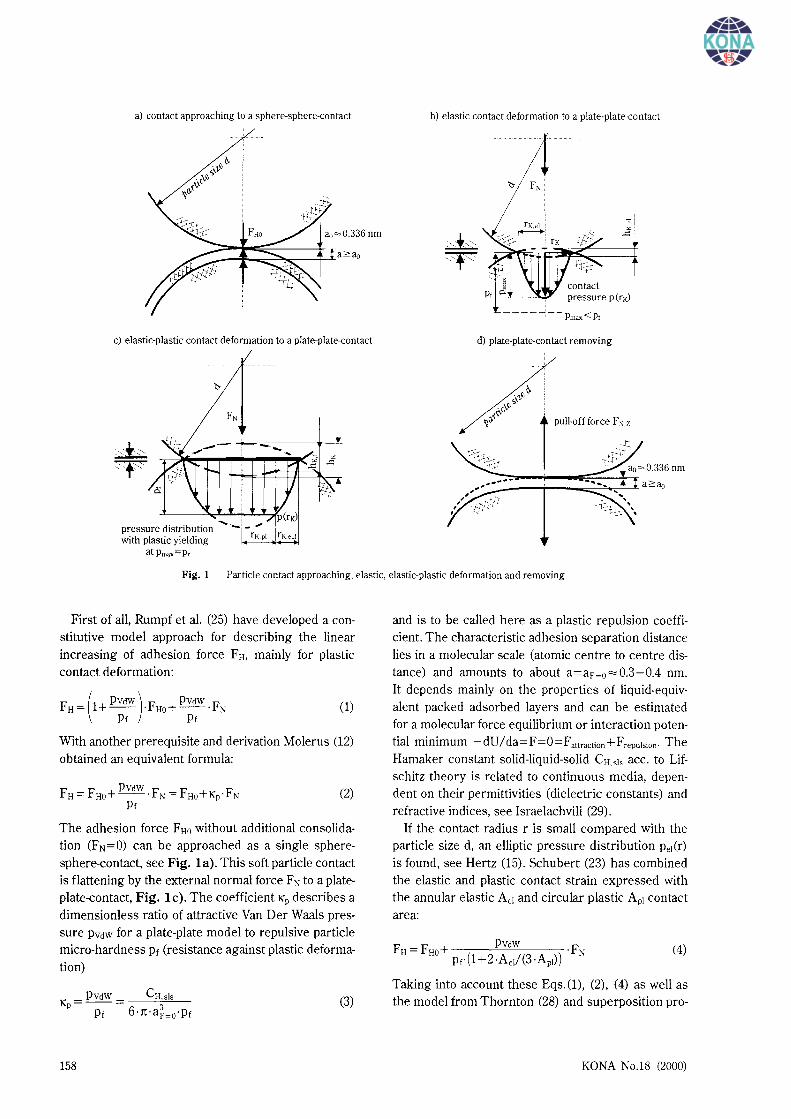
The dominant linear elastic-plastic deformation range between rea11y tested yield loci levels YLl to YL 4 is to be demonstrated in Fig. 2. The origin of this diagram hK=O is equivalent to the characteristic adhesion separation for a direct contact (atomic centre to centre distance) and can be estimated for a molecular force equilibrium a=ao=aF=O· Provided that these molecular contacts are stiff enough compared with the soft mesoscopic particle contact behaviour influenced by mobile adsorption layers due to molecular rearrangement, this separation aF~o is assumed to be constant during loading and unloading in the interesting macroscopic pressure range of cr=O.l-100 kPa. After loading 0-Y the contact is elastica1ly compacted with an approximated circular contact area, see Fig. lb) and starts at the yield pointY at Pmax=p1
macroscopic stress level ~ for yield locus YL4 with cr1 =33 kPa
20 elastic-plastic yield boundary
z <::
-; 15 ;...
5
elastic
KONA No.18 (2000)
Fig.2
~
0.15 0.2 0.25 0.3 force F
particle center approach h Kin nm 0 + compression
+press
I
strain h contact radius rK in nm 6 0 -pull -tension
material data:
E=50 kN/mm2 modulus of elasticity p1=400 N/mm2 plastic micro-yield strength v=0.28 Poisson number CH.sls= 12.6 10-zo] HAMAKER constant, solid-liquid-solid ao=0.336 nm molecular center distance for dipoles KA=5/6 contact area ratio Kp=0.44 plastic repulsion coefficient
Recalculated characteristic contact deformation ace. to Fig. 1 of very cohesive titania particles, median particle size d50.3=610 nm, moisture Xw=0.4%.
159
with plastic yielding, see Fig. 1c). Now, the combined elastic-plastic yield boundary of the plate-plate contact is achieved, see Eq.(6). This displacement is to be expressed with the annular elastic Ae1 (thickness rK.ei) and circular plastic Apl (radius rK.pi) contact area, see Fig. 1c). For comparison, a dashed line for the flowability limit ffc=2 (very cohesive ace. to Jenike (2)) is plotted additionally (32), see Fig. 2. After unloading U- E the contact recovers elastically in the compression mode and remains with an perfect plastic displacement hK.E· Below point E left the tension mode begins. Between U-E-A the contact recovers probably elastically along a supplemented Hertzian parabolic curvature up to a displacement hK.A· Along A-U the contact could be reloaded. If we apply a certain pull-off force F N.z=- F H. A. here negative, the adhesion (failure) boundary at point A is reached and the contact plates are failing and removing with the increasing distance a=aF=o+ hK.A- hK. This actual particle separation is to be considered for the calculation by means of a hyperbolic adhesion force curve FN.z=-FH.A oca-3 with the plate-plate model, see Eq.(3). These new models in Fig. 2 follow Molerus' (11), Schubert's (23), Maugis' (26) and especially Thornton's (28) example.
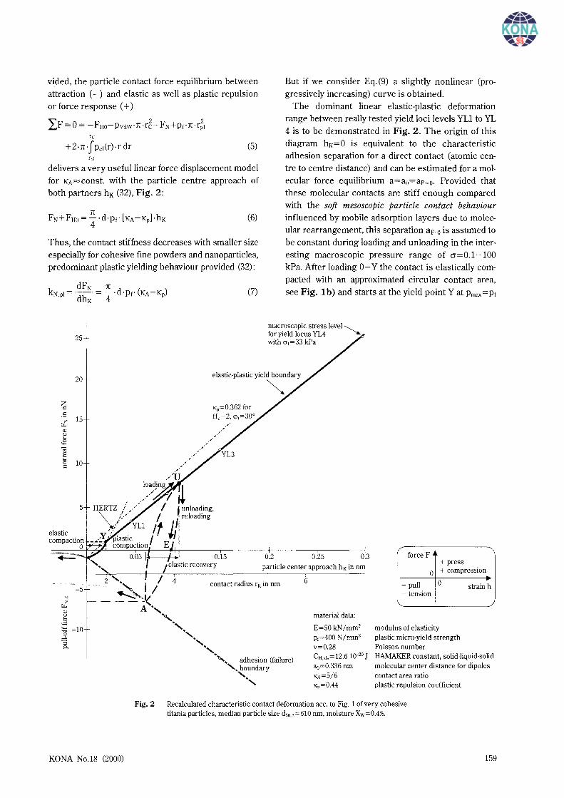
The slopes of plastic curves are a measure of irreversible particle contact stiffness or softness, resp. Thus the dimensionless contact consolidation coefficient (strain characteristic) K is read here as the slope of adhesion force, Fig. 3, influenced by predominant plastic contact failure.
(8)
The elastic-plastic contact area coefficient KA represents the ratio of plastic particle contact deformation area Ap1 to total contact deformation area AK=Ap1 + Ae1
40.----.----1-~o~.--~FH/(~F,\)~t=~O~hlr-------.r-~
z ::: 30 .s
Fig.3
160
--- FH,(F,) t=24 h
normal force F N in nN
Recalculated variable particle adhesion force of titania ace. to, median particle size d.';0=0.61 ~m, moisture Xw=0.4% accurately analysed with Karl Fischer titration
including a certain elastic displacement (32)
2 1 Apl 1 3 /hK.t KA= 3+3· AK = 1-3'\h;' (9)
with the centre approach hK.t for incipient yielding at Pel (r= 0) = Pmax =PI:
hKt=d· --( :n:·p1 )
2
. 2·E* (10)
The pure elastic contact deformation Ap1=0, KA=2/3, has no relevance for fine cohesive particles and should be excluded here. Commonly, for pure plastic contact deformation Ae1=0 or AK=Ap!. KA=1 is obtained. From Eq.(5), a linear model for the adhesion force FH as function of normal force F N is obtained again (32):
The contact consolidation coefficient K is a measure of irreversible particle contact stiffness or softness as well, see Fig. 3. A small slope stands for low adhesion level FH""FHo because of stiff particle contacts, but a large inclination means soft contacts or consequently, a cohesive powder flow behaviour, see Fig. 6 as well.
This model considers additionally the flattening of soft particle contacts caused by acting an adhesion force K · F HO· Herewith, the adhesion force F Ho for Ft-;=0 considers an essential characteristic micro roughness heighthr<d particle size (Schubert (30)):
FHo= CH,sls·(2·hr) ·l1+ d/hr ]= CH,sls'hr (12) 24 · a~=O 2 · (1 +hr/aF=o)2 12 · a~=O
The intersection of function (11) with abscissa (FH=O) in the negative extension range of consolidation force F N. Fig. 3, is surprisingly independent of the Hamaker constant CH,sls:
:n: ""--·aF-o·hr·Pt (13) 2 -
Considering the model prerequisites for cohesive powders, this minimum normal (tensile) force limit FN,z combines the influences of a particle contact hardness or micro-yield strength p1=3·cr1 (cr1 yield strength in tension) and particle separation distance distribution characterised by a particle roughness height hr as well as molecular centre separation distance aF=O· Obviously, this value characterises the contact softness with respect to a small asperity height hr as well, compare Eq.(7). It corresponds to an
KONA No.18 (2000)
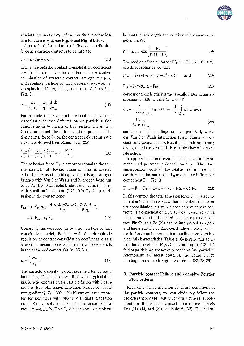
abscissa intersection O\z of the constitutive consolidation function crc(cr1), see Fig. 6 and Fig. 8 below.
A term for deformation rate influence on adhesion force in a particle contact is to be inserted
(14)
with a viscoplastic contact consolidation coefficient K1=attraction/repulsion force ratio as a dimensionless combination of attractive contact strength cra = Pvdw and repulsive particle contact viscosity llv/t = p1, i.e. viscoplastic stiffness, analogous to plastic deformation, Fig. 3.
Ga Ga d·dt Kt=--.-=-·--
llv · Ev r)v dr vis (15)
For example, the driving potential in the main case of viscoplastic contact deformation or particle fusion resp., is given by means of free surface energy <J55 •
On the one hand, the influence of the pre-consolidation normal force F :--; on the contact circle radius ratio rvis/d was derived from Rumpf et al. (25):
(16)
The adhesion force F Ht is set proportional to the tensile strength of flowing material. This is created either by means of liquid-equivalent adsorption layer bridges with Van Der Waals and hydrogen bondings
or by Van Der Waals solid bridges <Jzs = Ga and lls = r)v, with small melting point (0.75-0.9) ·Tm for particle fusion in the contact zone:
(17)
Generally, this corresponds to linear particle contact constitutive model, Eq.(14), with the viscoplastic repulsion or contact consolidation coefficient K1 as a slope of adhesion force when a normal force F :--; acts in the deformed contact (33, 34, 35, 36):
2·<Jzs Kt=--·t
5·r)s (18)
The particle viscosity lls decreases with temperature increasing. This is to be described with a typical thermal kinetic expression for particle fusion with 3 parameters (Ey molar fusion activation energy for shear rate gradient y, Tr= (200 .. .400) K temperature parameter for polymers with OK<Tr<TG glass transition point, R universal gas constant). The viscosity parameterr]s=lls.min forT>>Tm depends here on molecu-
KONA No.18 (2000)
Jar mass, chain length and number of cross-links for polymers (31).
lls = lls.min · exp [ R· (~~ Tr) l (19)
The median adhesion forces F~o and FHo. see Eq.(12), of a direct spherical contact
FHo,t = 2·rc·d·crss·K1(t) = F~o·K1 (t) and (20)
(21)
correspond each other if the so-called Derjaguin approximation (29) is valid (aF=o <<d)
1 X 1 X
Gss=-2
.A · J FHo(a)da=-z· J Pvdw(a)da C aF-o aF~o
CH,svs 24·rc·a}=o
(22)
and the particle bondings are comparatively weak, e.g. Van Der Waals interaction (CH.svs Hamaker constant solid-vacuum-solid). But, these bonds are strong enough to disturb essentially reliable flow of particu-late solids.
In opposition to time invariable plastic contact deformation, all parameters depend on time. Therefore superposition provided, the total adhesion force F Htot consists of a instantaneous FH and a time influenced component FHt, Fig. 3:
(23)
In this context, the total adhesion force F Htot is a function of adhesion force F Ho without any deformation or pre-consolidation in a very closed sphere-sphere contact plus a consolidation term (K+KJ · (F:--;+ FHo) with a normal force in the flattened plate-plate particle contact. Finally, this Eq. (23) can be interpreted as a general linear particle contact constitutive model, i.e. linear in forces and stresses, but non-linear concerning material characteristics, Table 1. Generally, this adhesion force level, see Fig. 3, amounts up to 105-106
fold of particle weight for very cohesive fine particles. Additionally, for moist powders, the liquid bridge bonding forces are strength determined (33, 38, 39).
3. Particle contact Failure and cohesive Powder Flow criteria
Regarding the formulation of failure conditions at the particle contacts, we can obviously follow the Molerus theory (14), but here with a general supplement for the particle contact constitutive models Eqs. (11), (14) and (23), see in detail (32). The inclina-
161
tion of radius and centre contact force components FR, FM and normal vectors are described with an angle a, see contact failure conditions in Table 1. It should be noted that the stressing pre-history of a cohesive powder flow is stationary (steady-state) and delivers significantly a cohesive stationary yield locus in radius- centre-stress coordinates,
(24)
with the isostatic tensile strength 0 0 obtained from the adhesion force FHo, see Eq.(12).
l-Eo FHo 0o=--·-
Eo d2 (25)
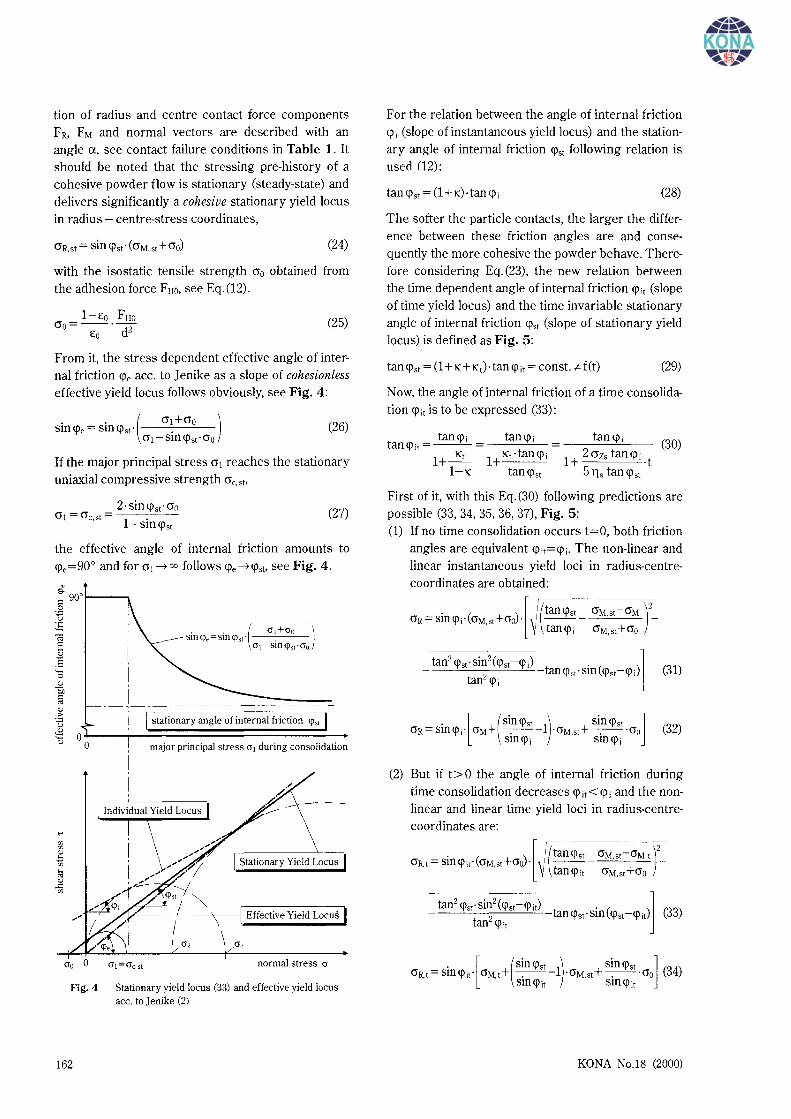
From it, the stress dependent effective angle of internal friction <!le ace. to Jenike as a slope of cohesionless effective yield locus follows obviously, see Fig. 4:
(26)
If the major principal stress 0 1 reaches the stationary uniaxial compressive strength 0c.st.
2 ·sin <!lst · 0o 01 = 0c,st = .
1-Sin<flst (27)
the effective angle of internal friction amounts to <fle=90o and for 0 1 ~ 00 follows <fle~<!lst. see Fig. 4.
cro 0
Fig.4
162
I
I
I
I --.,-------------------
1 stationary angle of internal friction <p"
major principal stress cr 1 during consolidation
normal stress cr
Stationary yield locus (33) and effective yield locus ace. to ] enike (2)
For the relation between the angle of internal friction <pi (slope of instantaneous yield locus) and the stationary angle of internal friction <!lst following relation is used (12):
tan <!lst = (1 + K) ·tan <pi (28)
The softer the particle contacts, the larger the difference between these friction angles are and consequently the more cohesive the powder behave. Therefore considering Eq.(23), the new relation between the time dependent angle of internal friction <!lit (slope of time yield locus) and the time invariable stationary angle of internal friction <!lst (slope of stationary yield locus) is defined as Fig. 5:
(29)
Now, the angle of internal friction of a time consolidation <flit is to be expressed (33):
(30)
1 2 crzs tan <fli + ·t 5 lls tan <!lst
First of it, with this Eq.(30) following predictions are possible (33, 34, 35, 36, 37), Fig. 5: (1) If no time consolidation occurs t=O, both friction
angles are equivalent <flit=<fli· The non-linear and linear instantaneous yield loci in radius-centrecoordinates are obtained:
. [ l(tan<pst 0M,st-0M )2
0R=smcpi·(0M,st+0o)· \I--- -~ tan 'Pi crM,st+0o
(31)
(32)
(2) But if t> 0 the angle of internal friction during time consolidation decreases <p;t<<p; and the nonlinear and linear time yield loci in radius-centrecoordinates are:
. [ (sin 'Pst ) sin 'Pst ] (3 ) 0R,t=smcp;t· 0M,t+ -.---l·0M,st+-.--·0o 4 smcp;t smcp;t
KONA No.l8 (2000)
i+s
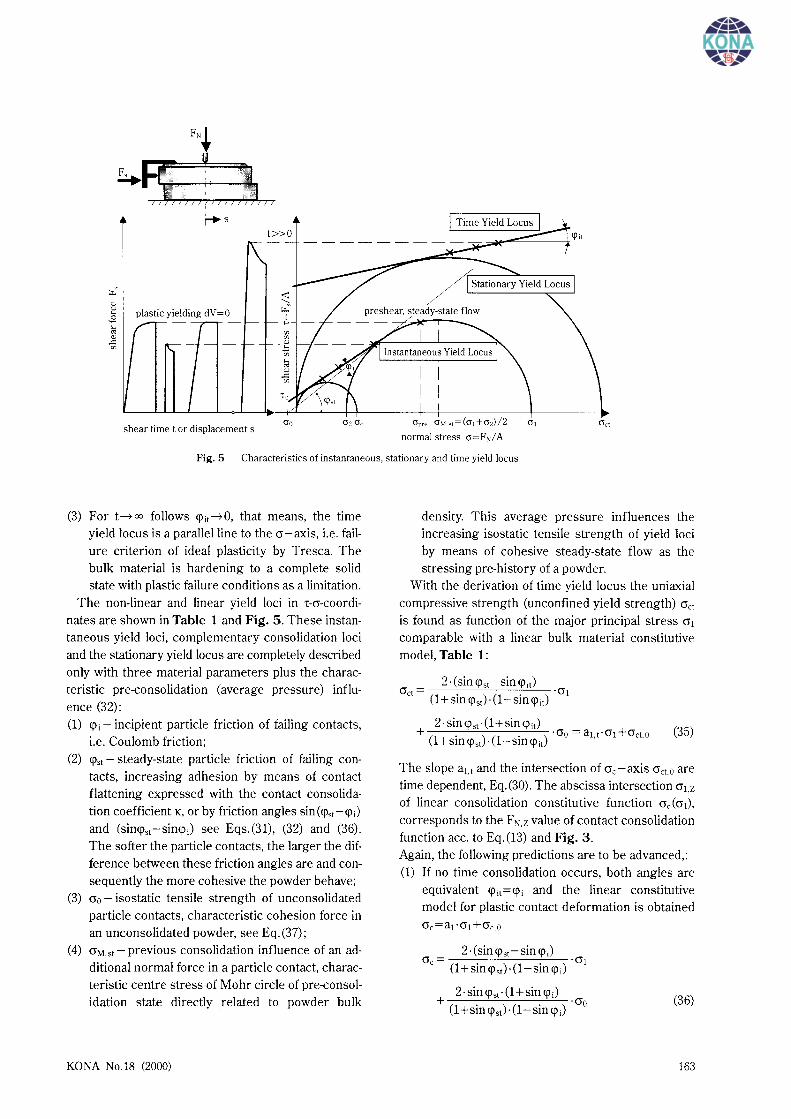
r..: "' 2 plastic yielding dV =0 ..;:: ... "' "" ..c: if)
shear time tor displacements Opce O~t>t=(o,+oz)/2 cr,
normal stress cr=F~/ A
Fig. 5 Characteristics of instantaneous, stationary and time yield locus
(3) For t~ oo follows <rit~o, that means, the time yield locus is a parallel line to the cr-axis, i.e. failure criterion of ideal plasticity by Tresca. The bulk material is hardening to a complete solid state with plastic failure conditions as a limitation.
The non-linear and linear yield loci in T-cr-coordinates are shown in Table 1 and Fig. 5. These instantaneous yield loci, complementary consolidation loci and the stationary yield locus are completely described only with three material parameters plus the characteristic pre-consolidation (average pressure) influence (32): (1) <pi- incipient particle friction of failing contacts,
i.e. Coulomb friction; (2) <rst - steady-state particle friction of failing con
tacts, increasing adhesion by means of contact flattening expressed with the contact consolidation coefficient K, or by friction angles sin(<p8t-<pi) and (sin<pst-sin<pi) see Eqs.(31), (32) and (36). The softer the particle contacts, the larger the difference between these friction angles are and consequently the more cohesive the powder behave;
(3) cr0 - isostatic tensile strength of unconsolidated particle contacts, characteristic cohesion force in an unconsolidated powder, see Eq.(37);
(4) crM,st- previous consolidation influence of an additional normal force in a particle contact, characteristic centre stress of Mohr circle of pre-consolidation state directly related to powder bulk
KONA No.18 (2000)
density. This average pressure influences the increasing isostatic tensile strength of yield loci by means of cohesive steady-state flow as the stressing pre-history of a powder.
With the derivation of time yield locus the uniaxial compressive strength (unconfined yield strength) cret is found as function of the major principal stress cr1 comparable with a linear bulk material constitutive model, Table 1:
2 ·(sin <rst- sin <rit) <Jet= . . ·(jl
(1 +Sill <rst) · (1- Sill <pit)
2 ·sin <rst· (1 +sin <rit) + (1 . ) (1 . ) ·cro = au·cr1 +cret.o (35)
+slll<pst · -Sill<pit
The slope au and the intersection of cre-axis cret,o are time dependent, Eq.(30). The abscissa intersection cr1,2 of linear consolidation constitutive function cre(cr1), corresponds to the FN,z value of contact consolidation function ace. to Eq.(13) and Fig. 3. Again, the following predictions are to be advanced,: (1) If no time consolidation occurs, both angles are
equivalent <rit=<pi and the linear constitutive model for plastic contact deformation is obtained
<Je=a1·<J1 +cre,O
2 ·(sin <rst- sin <pi) cre= ·(jl
(1 +sin <rstH1- sin <pi)
2· sin <rst" (1 +sin <pi) + ·cro
(1 +sin <rst) · (1- sin <pi) (36)
163
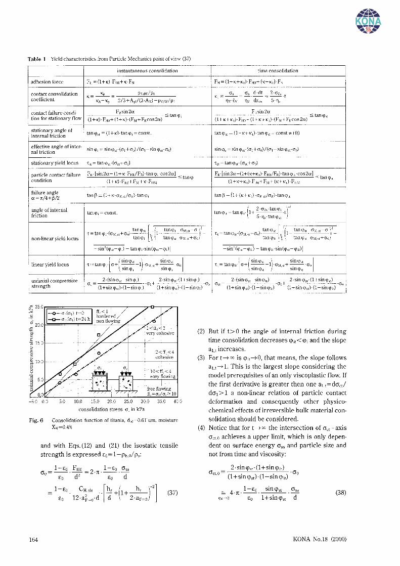
Table 1 Yield characteristics from Particle Mechanics point of view (37)
instantaneous consolidation time consolidation
adhesion force FH = (l+K)·FHo+K·FN FH = (l+K+K,)·FHo+ (K+K,)-F,
contact consolidation Kp Pvdw/Pr O'a O'a d·dt 2·0'zs coefficient
K=--= Kt X--=-·--= --·t KA-Kp 2/3+A,r/(3·AJ -PvctwiPr llv·Ev llv dr,;, S·lls
contact failure condi- FRsin2a FRsin 2a <:: tan<p, tion for stationary flow
<::tan <p; (1 +K)· FHo+ (1 +K)·(F ~1 + FRcos2a) (1 + K+K,)· F Ho+ (1 +K+K,)·(F ~1 + FRcos2a)
stationary angle of tan <p" = (1 + K) ·tan <p; = con st. tan<p" = (1 +K+K,) ·tan <p;, =canst* f(t)
internal friction
effective angle of inter- sin<p, =sin <p" ·(0'1 +cr0)/(cri-sin<p"·cro) sin<p, = sin<p"·(O't +cro)/(crt-Sin<p"·cro) nal friction
stationary yield locus '" = tan<p"·(cr"+cro) '" = tan<pst·Ccrst+O'o)
particle contact failure FR· [sin2a- (l+K·FHRIF0·tan<p.-cos2a] FR ·[sin 2a -(1+(K+K ,) · FHRIFR)· tan <p;, ·cos 2a] < tan<p; <::tan <p,,
condition (1 +K)·FHo+ FM+K·FHM (1 +K+K,)· FHo+ F,r+ (K+K,)· F mt
failure angle tanp = (l+K·O'R.stiO'R)·tan<p; tan P = (1 + (K+K,) ·O'Il.st/O'R)·tan <p;,
a=rr/4+P/2
angle of internal ( 2·0'z ·tan<p r tan <p; = con st. tan<p;,=tan<p;· 1+ ·' '·t friction S·lls·tan<pst
l ' l ( r tan<p" tan<p; O'~t.st-cr'· tan<p" tan <p;, O';t_st-0' -I T=tantj);-(O';t.st+O'o)·--· (1---·-_--)- 't,=tantj);,·(O'vt.st+O'o)·--· \ 1------- -
non-linear yield locus tan<p, \ tantj)" cr;u+O'o tan<pi1 tan<ps1 O\t.s1+ao
-sin2 (<p,, -<p;) -tan <p; ·sin (<p"-<p;)] -sin2 (<p" -<p,) -tan <p ,, ·sin (<p" -<p ;,)]
linear yield locus [ ( sin <p" ) sin <p" ] [ ( sin<p" ) sin<p" ] T=tantj);· cr+ _-. --1 ·O'~t.st+-. -·O'o T,=tantj);,· cr+ -.---1 ·O'vt.st+-.--·O'o Sin<p; Sin<p; sm <p;, sm <p;,
uniaxial compressive 2-(sin <p"-sin tj);) 2 ·sin tj),,. (1 +sin <p,) Gc = ·<J1 + ·(J(J
2 ·(sin <p"- sin <p;,) 2 ·sin <Jlst · (1 +sin <p;,) Get= ·crt+ ·all strength (1 +sin tj)")· (1-sin tj);) (1 +sin<p,,)·(l-sin tj);) (1 +sin<p")-(1-sin<p;,) (1 +sin<p")· (1-sin <p;,)
-5.0 0.0 5.0 10.0 15.0 20.0 25.0 30.0 35.0 40.0
consolidation stress cr 1 in kPa
Fig. 6 Consolidation function of titania. ds0 =0.6l!lm. moisture
Xw=0.4%
164
and with Eqs. (12) and (21) the isostatic tensile
strength is expressed Eo= 1-Pb.o/ Ps:
(37)
(2) But if t>O the angle of internal friction during
time consolidation decreases <l>it<<t>i and the slope au increases.
(3) Fort~ x is <l>it~o. that means, the slope follows au~ 1. This is the largest slope considering the model prerequisites of an only viscoplastic flow. If the first derivative is greater then one au=dO'ctl da1 > 1 a non-linear relation of particle contact deformation and consequently other physicochemical effects of irreversible bulk material consolidation should be considered.
(4) Notice that for t~x the intersection of O'ct-axis O'ct.o achieves a upper limit, which is only dependent on surface en~rgy 0 55 and particle size and not from time and viscosity:
2 ·sin <i>st · (1 +sin <pit) O'ct.o= ·O'o
(1 +sin <i>st) · (1- sin <pit)
= 4·1t·1-£o. sin<pst O'ss <p;, -->O £o 1 +sin <i>st d
(38)
KONA No.l8 (2000)
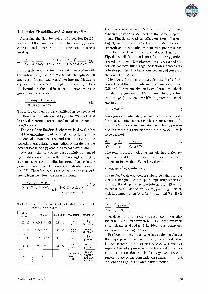
4. Powder Flowability and Compressibility
Assessing the flow behaviour of a powder, Eq.(35) shows that the flow function ace. to Jenike (2) is not constant and depends on the consolidation stress level cr1:
cr1 1 (1+sinq\tH1-sin<pit) ffct = - = - · (39)
O"ct 2 sin <jlst -sin <!'it+sin <!'st · (l+sin <!'it) ·cro/ 0"1
But roughly we can write for a smaii intersection with the ordinate Gc.o, i.e. isostatic tensile strength cr0~0 near zero, the stationary angle of internal friction is equivalent to the effective angle <pst "-"' <!'e and J enike's (2) formula is obtained in order to demonstrate the general model validity:
ff """' (1 +sin <pe)-(1- sin <p J c 2· (sin <re-sin<pi)
(40)
Thus, the semi-empirical classification by means of the flow function introduced by Jenike (2) is adopted here with a certain particle mechanical sense completion, Table 2:
The class "non flowing" is characterised by the fact that the unconfined yield strength O"ct is higher than the consolidation stress cr1 and thus in case of time consolidation, caking, cementation or hardening the powder has been agglomerated to solid state (38).
Obviously, the flow behaviour is mainly influenced by the difference between the friction angles, Eq.(40), as a measure for the adhesion force slope K in the general linear particle contact constitutive model, Eq.(23). Therefore we can recalculate these coefficients from flow function measurements:
1 1 (41)
1_ (1 +(2 · ffc-1)· sin <pi )2
. 2·ffc-1 +sin <pi
Table 2 Flowability assessment and elastic-plastic contact consolidation coefficient K(<(l;=30°)
flow K-values 'll« in deg evaluation examples function ff,
100-10 0.01006-0.1068 30.3-33 free dry flowing fine sand
4-10 0.1068-0.3 33-37 easy moist flowing fine sand
2-4 0.3-0.77 37-46 cohesive dry powder
1-2 0.77-co 46-90 very moist cohesive powder
non-flowing, moist
<1 00 - hardened powder,
(ffn) hydrated cement
KONA No.18 (2000)
A characteristic value K=0.77 for <pi=30o of a very cohesive powder is included in the force displacement, Fig. 2, as well as adhesion force diagram, Fig. 3, and shows directly the correlation between strength and force enhancement with pre-consolidation, Table 2. Due to the consolidation function in Fig. 6, a small slope stands for a free flowing particulate solid with very low adhesion level because of stiff particle contacts, but a large inclination means a very cohesive powder flow behaviour because of soft particle contacts, Fig. 3.
Obviously, the finer the particles the "softer" the contacts and the more cohesive the powder (33, 42). Kohler (43) has experimentaily confirmed this thesis for alumina powders (a-A]z03) down to the submicron range (crc,o""'Const.=2 kPa, d50 median particle size in 11m):
(42)
Analogously to adiabatic gas law p·Vl(ad=const., a differential equation for isentropic compressibility of a powder dS=O, i.e. remaining stochastic homogeneous packing without a regular order in the continuum, is to be derived:
dpb dp dcr:-.l.st -=n·-=n· Pb P 0":-.f,st+Go
(43)
The total pressure including particle interaction p= 0":.1,st+cr0 should be equivalent to a pressure term with molecular interaction CVm molar volume)
(44)
in Van Der Waals equation of state to be valid near gas condensation point. A loose powder packing is obtained Pb=Pb.o, if only particles are interacting without an external consolidation stress cr:.f.st=O, e.g. particle weight compensation by a fluid drag, and Eq.(43) is solved:
~ = (cro+crM,st )n Pb.o Go
(45)
Therefore, this physicaily based compressibility index n = 1/Kad lies between n=O, i.e. incompressible stiff bulk material and n = 1, i.e. ideal (gas) compressibility index, see Fig. 7 above.
For hopper design purposes in powder mechanics the major principle stress cr1 during preconsolidation is used instead of the centre stress crM.st· Hence we replace the total pressure p=cr1 +crl.Z with the new abscissa intersection O"tz in the negative tensile or puii-off range of the consolidation function crc=f(cr1),
Eq.(36) and Fig. 7, and obtain this function:
165
isostatic 0 tensile strength O"o
n= 1 ideal gas compressibility index
O<n<1
center stress during consolidation or steady-state flow crM.$1
Fig. 7 Compr<ossibility index n of powders
(46)
Considering the predominant plastic and viscoplastic particle contact deformation and rearrangement in
the stochastic homogeneous packing of a cohesive powder, following values of compressibility index are to be suggested, Table 3:
Table 3 Compressibility index of powders, semi-empirical estimation for cr 1 = 1-100 kPa
index n evaluation examples flowability
0-0.01 incompressible gravel free flowing
0.01-0.05 low compressibility fine sand
0.05-0.1 compressible dry powder cohesive
0.1-1 very compressible moist powder very cohesive
5. Design Consequences for Reliable Flow
Mainly for functional silo design purposes in
Mechanical Process Engineering, these fundamental models can be applied by means of a characteristic apparatus dimension function, here a minimum hop
per opening width bmin.t avoiding cohesive bulk material arches (g gravitational acceleration, ff flow factor ace. to Jenike, m=1 conical hopper, m=O wedge hop
per, <j)w angle of wall friction, 8 hopper angle versus vertical, Ph bulk density): (1) If no time consolidation occurs t=O, both friction
angles are equivalent <pi1=<pi and the linear bulk material constitutive model for plastic contact
deformation is obtained. Consequently it is:
b . = 2· (m+ 1)·sin2(qlw+8)·(1 +sinqJJsinqlst·O"o (47
) mm Ph· g · [1-sinqJ 51 ·sinqJi- (sin ql,t-sinqJJ·(2 ·ff-1)]
(2) For the general case t>O the angle of internal
friction during time consolidation decreases
<j)i1<<pi. the slope al,t and bmin.t increase:
b . 2· (m+ l)·sin2(qlw+8)·(1 tsinqlit)·sinqlst·O"o (4
S) mm.t Pb·g · [1-sin ql 51 ·sinqli1- (sin ql 51-sinqlit)·(2 ·ff-1)]
166
(3) Often a technological unreasonable time independent limit bmin, 1(t-7 oo) follows for an extreme
hardening or agglomerating particle material:
1. b . __ 4 _·Jt_· ('-m_+_1"-) ·_s_in_2_-'-( <pw'-'--+_8....;_)_· s_in_<p=st . O'ss (49
) lffi mmt--P:-
~--'" · p,·£o·g·[l-sin<p51 ·(2·ff-1)] d
This approach should express the enormous problems concerning reliable flow of powders which are
tending to time consolidation, hardening and caking. Consequently, discharging aids should be applied in handling practice (33).
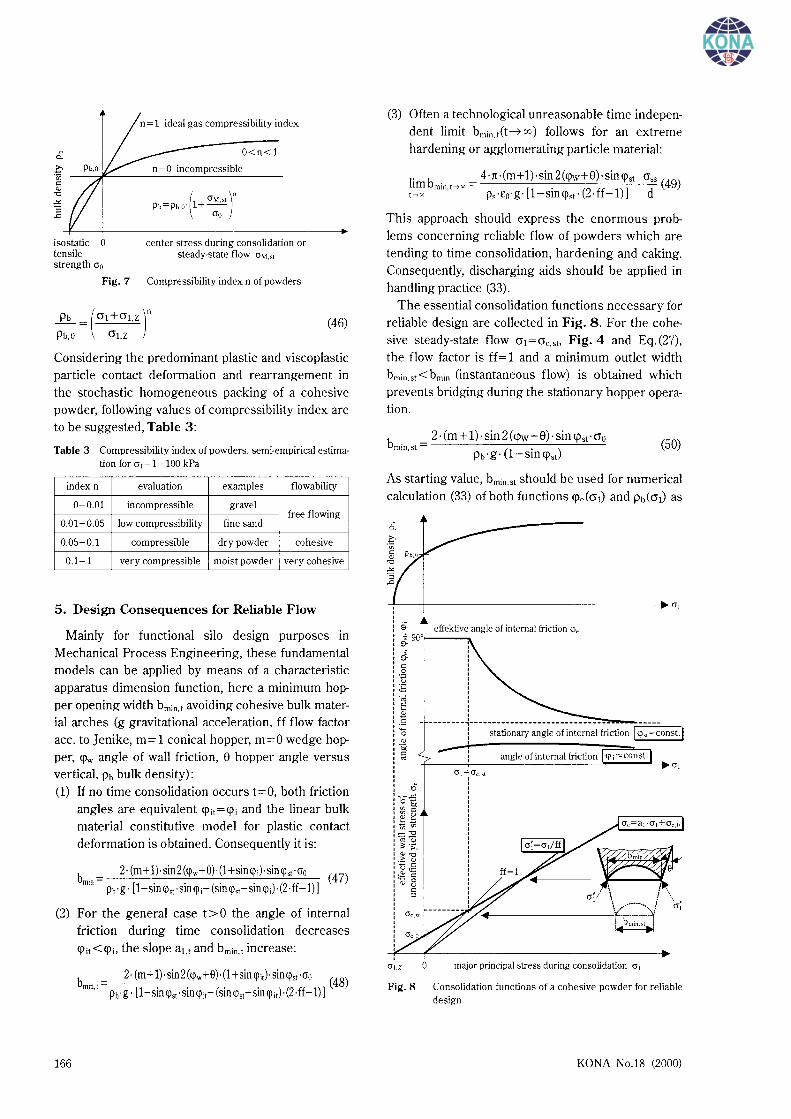
The essential consolidation functions necessary for reliable design are collected in Fig. 8. For the cohe
sive steady-state flow cr1 =crc,st. Fig. 4 and Eq. (27), the flow factor is ff= 1 and a minimum outlet width
bmin.st<bmin (instantaneous flow) is obtained which prevents bridging during the stationary hopper operation.
b . _ 2·(m+1)·sin2(<pw+8)·sin<p51 ·cr0
mm,st- (1 . ) (50) Pb·g· -Slll<j)st
As starting value, bmin,st should be used for numerical calculation (33) of both functions <j)e(cr1) and Pb(cr1) as
-----I•~ a,
9- effektive angle of internal friction cp, ~ goof------,.
~ c .g u
:E -;;:; E "' .S 0 "' '& c "'
- --------, ________________________ ;::: ___ ~--~---r==-=---. ! stationary angle of internal friction I cp,1=const.j I
~;: angle of internal friction I <p; = const.j +---~--~~~~~~~~~~~~~cr,
\ I
~~~---------r~~~~::r crl.Z 0 major principal stress during consolidation cr 1
Fig. 8 Consolidation functions of a cohesive powder for reliable design
KONA No.18 (2000)
well as the flow factor (1, 2) ff (<pe(cr1), <pw). Before that the hopper angle e(<pe(O"j), <pw) has properly to be selected (1, 2, 4, 5, 13).
For the sub-micron titania powder (d50,3=610 nm, cr0 =0.327 kPa, Pb""'800 kg/m3, friction angles <j)i=33°, <j)st=54°, <pw=31 °, 8=11 °, ff""'L3) practically reasonable bmin,st=0.7 m for steady-state flow, but bmin=L52 m for incipient yield and incredible bmin,t=8.4 m for gravitational flow (without flow promotion) after time consolidation at rest (t=24 h, <pit=31 °) are determined for a conical hopper.
Both, shear test results - accurate measurements provided - evaluated with these combined particle and continuum mechanical approach, are used as constitutive functions for computer aided silo design for reliable flow (37) on the one hand. On the other hand a supplemented slice-element standard method (41, 42) is used for pressure calculations. Considering the reliable physical basis of the Pb(cr1) and <pe(cr1) functions for example, these can be suitably extrapolated using pressure calculations for large silos with more than 1000 m3 storage capacity (44).
6. Conclusions
Taking into consideration all the different properties of cohesive to very cohesive powders tested (particle size distribution, moisture content, material properties etc.), the model fit can be characterised as satisfactory to good. Thus, the model has proved its effectiveness and can be accordingly applied in reliable silo design for flow and pressure calculation.
Obviously, recommendations are to be elaborated with respect to the powder product design for processing, logistics, transportation, distribution and consumption, see Borho et al. ( 45) as well.
7. Acknowledgements
The author would like to acknowledge his co-workers Dr. S. Arnan, Dr. T. Groger, S. Schubert, B. Reichmann and Th. Kollmann for their experimental contributions, relevant information and theoretical tips.
Symbols
a : separation a1 : slope of crc(cr1) consolidation function A : area, particle contact area b : outlet width CH : Hamaker constant d : particle size
KONA No.18 (2000)
[m] [-]
[m2]
[m]
Ul [~-tml
E : modulus of elasticity F : force ff : flow factor ace. to J enike ffc : flow function ace. to J enike g : gravity acceleration m : mass, hopper shape factor p :pressure
[kN/mm2]
[N] [-]
[-]
[m/s2]
[kg,-] [kPa]
Pt : plastic yield strength of particle contact [MPa]
[~-tml [deg] [deg]
r : contact radius a : failure angle ~ : auxiliary failure angle function y : shear deformation rate gradient
:porosity £
£ : deformation rate gradient 11 : viscosity TJv : viscoplastic yield strength of particle
contact K : contact consolidation coefficient e : hopper angle <p : angle of friction p : density a : normal stress O"a : adhesion strength cr1 : major principal stress a0 : isostatic tensile strength 1: : shear stress
Indices
ad :adiabatic b :bulk c : compressive e :effective el : elastic H : adhesion (Haft-)
:internal K : total contact 1 : liquid m :molar M : centre of Mohr circle min :minimum N :normal p :pressure pl : plastic pre :pre-shear R : radius of Mohr circle s : solid st : stationary t : time dependent T : tangential v :volume VdW :Van DerWaals
[s-I]
[-] [s-I]
[Pa·s]
[Pa-s] [-]
[deg] [deg]
[kg/m3]
[kPa] [kPa] [kPa] [kPa] [kPa]
167
vis : viscoplastic W :wall Z : tensile (Zug-) 0 : initial, zero point
References
1) A. W. Jenike, "Gravity flow of solids", Engng. Exp. Station Bull. No. 108, Univ. Utah, (1961)
2) A. W. Jenike, "Storage and flow of solids", Engng. Exp. Station Bull. No. 123, Univ. Utah, (1964)
3) F. Ziegler, "Techn. Mechanik der festen und f!i.issigen Korper", Springer Verlag Wien (1985)
4) }. Schwedes, "FlieEverhalten von Schi.ittgi.itern in Bunkern", Verlag Chemie Weinheim (1970)
5) }. Schwedes and H. Wilms, "FlieEeigenschaften von Schi.ittgi.itern", pp. 39-58, edited by P Martens, "Silo -Handbuch", Ernst & Sohn Berlin (1988)
6) Ashton, M. D., Cheng, D. C. D., Farley, R. and Valentin, F. H. H., Some investigations into the strength and flow of powders, Rheolog. Acta 4 206-218 (1965)
7) Cheng, D. C. H., The tensile strength of powders, Chem. Engng. Sci. 23 1405-1420 (1968)
8) Stainforth, P T., Ashley, R. C., and Morley, ]. N. B, Computer analysis of powder flow characteristics, Powder Technology 4 250-256 (1971)
9) Stainforth, P T. and Ashley, R. C., An analytical hopper design method for cohesive powders, Powder Technology 7 215-243 (1973)
10) Stainforth, PT. and Berry, R. E. R., A general flowability index for powders, Powder Technology 8 243-251 (1973)
11) 0. Molerus, "Theory of yield of cohesive powders", Powder Technology 12 259-275 (1975)
12) 0. Molerus, "Effect of interparticle cohesive forces on the flow behaviour of powders", Powder Technology 20 161-175 (1978)
13) 0. Molerus, "Schi.ittgutmechanik- Grundlagen und Anwendungen in der Verfahrenstechnik", Springer Verlag Berlin (1985)
14) 0. Molerus, "Principles of Flow in Disperse Systems", Chapman & Hall London (1993)
15) H. Hertz, "Uber die Beri.ihrung fester elastischer Korper", ]. reine u. angew. Math. 92 156-171 (1882)
16) M. T. Huber, "Zur Theorie der Beri.ihrung fester elastischer Korper",Annal. Physik 14153-163 (1904)
17) Mindlin, R. D. and Deresiewicz, H., Elastic spheres in contact under varying oblique forces, ]. Appl. Meek., Trans. ASME 20 327-344 (1953)
18) Krupp, H., Particle Adhesion - Theorie and Experiment, Advanced Colloid Interface Sci. 1111-239 (1967), in (11)
19) Dahneke, B., The influence of flattening on the adhesion of particles,]. Colloid and Interface Sci. 40 1-13 (1972)
20) Derjagin, B. V., Muller, V. M., Toporov, U. P, Effect of contact deformations on the adhesion of particles, ]. Colloid and Interface Sci., 53 314-326 (1975)
21) Johnson, K. L., Kendall, K. and Roberts A. D., Surface
168
energy and the contact of elastic solids, Proc. Roy. Soc. Lond. A 324 301-313 (1971), in (22)
22) K. L. Johnson, "Contact Mechanics", Cambridge University Press (1985)
23) H. Schubert, K. Sommer and H. Rumpf, "Plastisches Verformen des Kontaktbereiches bei der Partikelhaftung", Chemie Ingenieur Technik 48 716 (1976)
24) Wei Hsuin Yang, The contact problem for viscoelastic bodies,]. Appl. Meek., Trans. ASME 33 395-401 (1966)
25) H. Rumpf, K. Sommer and K. Steier, "Mechanismen der Haftkraftverstarkung bei der Partikelhaftung durch plastisches Verformen, Sintern und viskoelastisches FlieEen", Chemie Ingenieur Technik 48 300-307 (1976)
26) Maugis, D. and Pollock, H. M., Surface forces, deformation and adherence at metal microcontacts, Acta Metal!. 32 1323-1334 (1984)
27) Thornton, C. and Yin, K. K., Impact of elastic spheres with and without adhesion, Powder Technology 65 153-166 (1991)
28) Thornton, C. and Ning, Z., A theoretical model for the stick/bounce behaviour of adhesive, elastic-plastic spheres, Powder Technology 99 154-162 (1998)
29) ]. N. Israelachvili, "Intermolecular and surface forces", Academic Press London (1992)
30) H. Schubert, "Kapillaritiit in porosen Feststoffsystemen", Springer Verlag Berlin (1982)
31) H. Domininghaus, "Die Kunststoffe und ihre Eigenschaften", VDI Verlag DUsseldorf (1992)
32) ]. Tomas, Particle Adhesion and Powder Flow Properties- Part I: Instantaneous Elastic-Plastic Particle Contact Consolidation and Yield Loci, Powder Technology (2001), (submitted)
33) }. Tomas, "Modellierung des FlieEverhaltens von Schi.ittgi.itern auf der Grundlage der Wechselwirkungskrafte zwischen den Partikeln und Anwendung bei der Auslegung von Bunkeranlagen", Habilitation, Bergakademie Freiberg (1991)
34) ]. Tomas, "Modelling the Time Consolidation Processes of Bulk Materials - Problems and Preliminary Solutions", International Symposium "Reliable Flow of Particulate Solids II" Oslo, Proceedings, 335-372 (1993)
35) ]. Tomas, "Zum VerfestigungsprozeE von Schi.ittgi.itern - Mikroprozesse, Kinetikmodelle und Anwendungen", Schiittguttechnik 2 31-51 (1996)
36) ]. Tomas, "Zur Verfestigung von Schi.ittgi.itern- Mikroprozesse und Kinetikmodelle" Chemie Ingenieur Technik 69 455-467 (1997)
37) }. Tomas, Particle adhesion fundamentals and bulk powder consolidation, International Symposium "Reliable Flow of Particulate Solids III", Porsgrunn, 641-656, 1999
38) ]. Tomas and H. Schubert, "Modelling of the strength and flow properties of moist soluble bulk materials", International Symposium on Powder Technology Kyoto, Proceedings (1982)
39) ]. Tomas and H. Schubert, "Modelling of the strength and the flow properties of moist soluble bulk materials", Aufbereitungs-Technik 23 507-515 (1982)
40) }. Tomas and H. Schubert, "Flow behaviour of moist
KONA No.18 (2000)
bulk materials", Au/bereitungs-Technik: 26 399-404 (1985) Part. Part. Syst. Charact. 8 101-104 (1990) 41) TGL 32 274/09, "Lasten aus Schiittgiitern in Bunkern,
Flachsilos und Silos", (1987) 42) Tomas, ]., Graichen, K. and Schubert, H., Influence of
Flow Properties of Particulate Solids on Silo Pressure Calculation, Aujbereitungs-Technik 31 4 75-481 (1990)
44) Fliigel, R., 6400 t potato starch in a "first in - first out" mode mammoth silo, powder handling & processing 11 37 4-375 (1999)
43) Kohler, Th. and Schubert, H., Influence of particle size distribution on the flow behaviour of fine powders,
45) Borho, K., Polke, R., Wintermantel, K., Schubert, H. and Sommer, K., Produkteigenschaften und Verfahrenstechnik, Chem.-Ing.-Techn. 63 792-808 (1991)
Author's short biography I
KONA No.18 (2000)
Jiirgen Tomas
]. Tomas studied process engineering, special field system engineering, at the Institute of Technology (TH) Merseburg from 1971 to 1975. He finished his studies with Diploma-theses concerning crystallization and particle agglomeration in a liquid fluidized bed reactor. After his research work at the department of Mechanical Process Engineering and Mineral Processing of the Institute of Mining Technology (Bergakademie) Freiberg, he wrote his PhD-theses "Investigations on Flow Behaviour of Moist Soluble Bulk Materials" in 1982. RID-activities followed this work, e.g. design of silo plants for power stations, cement mills, process industries as well as port installations for ores, consultant for trouble shouting in chemical plants. From 1988 to 1989, he teached as Assistant Professor at the Addis Abeba University (Ethiopia). In 1991 he wrote the SeD-theses (Habilitation) "Modelling the Flow Behavior of Bulk Materials on Particle Interaction Forces Basis and Application in Bunker Plant Design" at the Bergakademie Freiberg. After substituting a professorship in Mechanical Process Engineering at the Bergakademie Freiberg from 1992 to 1993, he was appointed professor at the School of Technology (HTWS) Zittau/Gorlitz and, in 1994, full professor at the Otto-von-GuerickeUniversity Magdeburg. From 1995 to 1997, he was chairman of the joint research field 385 (DFG Sonderforschungsbereich) "Building Material Recycling". His principal research activities are in particle characterization, particle and powder mechanics, comminution, solid-solid separation, press filtration, bulk solids storage and handling.
169


![SHOCK CONSOLIDATION OF POWDERS - THEORY AND ......140 ume of the solid. A shock consolidation map for AISI 9310 steel powder has been previously reported [1]. The present shock recovery](https://static.fdocuments.us/doc/165x107/6030afbfb623c163b86e6a35/shock-consolidation-of-powders-theory-and-140-ume-of-the-solid-a-shock.jpg)
