PARTIAL OXIDATION GAS-TURBINE BASED TURBO …members.igu.org/old/IGU...
14
International Gas Union Research Conference 2014 PARTIAL OXIDATION GAS-TURBINE BASED TURBO-POx SYNGAS GENERATION TECHNOLOGY FOR GTL APPLICATIONS Arun Basu ([email protected]) Howard Meyer ([email protected]) Jim Aderhold ([email protected]) Bruce Bryan ([email protected]) Andrew Kramer ([email protected]) Vann Bush ([email protected]) Gas Technology Institute 1700 S. Mount Prospect Rd. Des Plaines, Illinois 60018 www.gastechnology.org
-
Upload
hoangduong -
Category
Documents
-
view
222 -
download
3
Transcript of PARTIAL OXIDATION GAS-TURBINE BASED TURBO …members.igu.org/old/IGU...

International Gas Union Research Conference 2014
PARTIAL OXIDATION GAS-TURBINE BASED TURBO-POx SYNGAS
GENERATION TECHNOLOGY FOR GTL APPLICATIONS
Arun Basu
Howard Meyer
Jim Aderhold
Bruce Bryan
Andrew Kramer
Vann Bush
Gas Technology Institute 1700 S. Mount Prospect Rd. Des Plaines, Illinois 60018 www.gastechnology.org

POGT Turbo-POx Syngas Page ii
ABSTRACT
With financial assistance from the Advanced Research Projects Agency – Energy (ARPA-E) -
U.S. Department of Energy, Aerojet Rocketdyne Energy Systems Inc. (AR) and Gas Technology
Institute (GTI) are collaborating in developing a novel non-catalytic, partial-oxidation based,
syngas generation technology called Turbo-POx for Gas-to-Liquids (GTL) and other industrial
applications. AR is a leader in high energy density propulsion and power systems with over five
decades of combustion and high-pressure turbine development experience. GTI is a not-for-profit
R&D organization with over seven decades of experience in energy conversion and monetization
of natural resources including natural gas, biomass and coal. The Turbo-POx technology is based
on GTI’s patented Partial Oxidation Gas Turbine (POGT) concept in which hot synthesis gas
from AR’s non-catalytic POx gasifier is rapidly cooled in a close-coupled turbo-expander instead
of in a conventional waste-heat boiler (WHB). Thus, a considerable portion of the sensible waste
heat in the hot synthesis gas is recovered as electrical power and high-pressure steam, thereby
resulting in significant capital cost savings compared to a conventional WHB-based synthesis
gas cooling process. The AR-POx unit is capable of operating at about 1,500 psia and 2,400 °F
outlet conditions using a relatively low steam/carbon molar ratio (typically, ~0.2). The AR turbo-
expander would be cooled by the POx gasifier’s reactants via a patented regenerative (regen)
cooling concept for improved thermal efficiency and for enhanced service life of expander
blades. For the integrated AR-POx/expander commercial operation for a nominal 1,000
barrels/day GTL plant, a typical AR turbo-expander system is projected to deliver an electrical
power output of about 6 MWe. Key applications of the POGT/Turbo-POx technology would
include GTL and polygeneration of electricity and chemicals.
POGT Turbo-POx Syngas Page
Table of Contents
ABSTRACT ................................................................................................................................. ii
Table of Contents .........................................................................................................................
Table of Figures ...........................................................................................................................
Table of Tables ............................................................................................................................ i
INTRODUCTION ....................................................................................................................... 1
TYPICAL PROCESS CONFIGURATIONS FOR FT AND MTG-TYPE GTL PROCESSES......... 1
FT GTL Process for the Production of Diesel/Naphtha .............................................................. 1
STG+ GTL Gasoline Production Process ................................................................................... 2 KEY SYNGAS GENERATION PROCESSES ............................................................................ 3
Non-catalytic Partial Oxidation (POx) ........................................................................................ 3 Conventional Steam Methane Reforming (SMR)....................................................................... 4
Conventional Catalytic ATR (Autothermal Reformer) .............................................................. 5 Haldor Topsoe ATR/GHR Integration to Reduce Cost for Syngas Production ......................... 5
GTI’s PATENTED POGT CONCEPT FOR CO-PRODUCING SYNGAS PLUS ELECTRICTY FROM NATURAL GAS .............................................................................................................. 6
AR Gas-based POx Development Reactor at GTI ...................................................................... 7 AR Expander Development ........................................................................................................ 7
Specific Details on the AR Reducing Gas Expander .................................................................. 8 KEY POTENTIAL ADVANTAGES FOR TURBO-POx vs. CATALYTIC ATR .............................. 8
Estimates on Capital Costs (CAPEX) for Steam-based Systems in an ATR-based FT Plant .... 8 Key Potential Advantages for Turbo-POx over Conventional Catalytic ATR ........................... 9
SUMMARY AND CONCLUSIONS ............................................................................................. 9
ACKNOWLEDEMENT ..............................................................................................................10
REFERENCES .........................................................................................................................10
Table of Figures
Page Figure 1 Typical Process Flow Diagram for a FT GTL Process .................................................. 2
Figure 2 (a): Experimental data for C5+ and CO2 Selectivity, and (b): Improvements in C5+ selectivity with decreasing H2/CO molar ratio around 2.0 ........................................................... 2
Figure 3 Typical Process Flow Diagram for Primus’ Syngas-to-Gasoline (STG+) Process ......... 3
Figure 4 Schematic of the Shell Non-Catalytic POx Process for FT ........................................... 3
POGT Turbo-POx Syngas Page i
Figure 5 Typical Process Flow Diagram for Conventional Steam Methane Reforming ............... 4
Figure 6 Potential Use of CO2-rich Feed Gas for Syngas Production in a Methanol Plant .......... 4
Figure 7 Typical Process Flow Diagram for a Conventional Catalytic ATR Process for FT ......... 5
Figure 8 A Schematic of the HTAS ATR Reactor ....................................................................... 5
Figure 9 Typical Flow Diagram for Haldor Topsoe ATR + GHR (Haldor Topsoe Gas Heated Reformer) ................................................................................................................................... 6
Figure 10 GTI’s Patented POGT Syngas Generation Concept using AR’s Turbo-POx for GTL Applications ............................................................................................................................... 7
Figure 11 AR POx Development Combustor at GTI ................................................................... 7
Figure 12 Schematic of a Specific Design for AR’s Reducing Gas Expander ............................. 8
Figure 13 Specific Details on the AR Reducing Gas Expander .................................................. 8
Table of Tables
Table 1 Impact of Reduced S/C ratio on ATR and ATR/GHR Performance – Haldor Topsoe Study ......................................................................................................................................... 6
Table 2 Specific Details on the AR Reducing Gas Expander ...................................................... 9

POGT Turbo-POx Syngas Page 1
INTRODUCTION
With the ongoing shale gas revolution in the U.S., extensive global exploration for
shale/conventional natural gas reserves, and concerns with climate change linked to gas flaring,
the interest in Gas-to-Liquids (GTL) processes as a way of monetizing low cost natural gas
(associated, flared and remote) is growing rapidly. Although key GTL technologies (namely,
Sasol/Shell Fischer Tropsch (FT) processes for the production of diesel and ExxonMobil’s MTG
(Methanol to Gasoline) option for the production of gasoline) have been commercialized, there
has been strong ongoing R&D focus on further reductions of total capital cost which is the
primary component of the overall production costs for gas-based transportation fuels. Syngas
(primarily, a mixture of hydrogen and carbon monoxide) generation from feed gas is a key step
in current commercially proven GTL technologies. In this context, the Syngas Generation
Process (SGP) step itself accounts for about 40-60% of the total plant investment. The manner in
which syngas is produced can be greatly influenced by various aspects of the overall GTL
process design, such as:
Plant capacity and location;
The need for an oxygen (or enriched air) plant and associated safety issues (e.g., offshore
locations);
Syngas composition (primarily, H2/CO ratio and level of CO2) and how it impacts
optimum product yields and selectivities;
Need for gas recycle and its impact on GTL production costs;
Configuration and optimization of power/steam generation facilities;
Potential for modular construction and shop fabrication to reduce plant CAPEX; and
Economics for CO2 capture, and utilization of low-cost CO2, if available at the plant site.
In this paper, we briefly outline the R&D status and economic potential of GTI’s patented POGT
(Partial Oxidation Gas Turbine) technology for syngas generation and its integration with the
Turbo-POx concept currently being developed by Aerojet-Rocketdyne (AR) under the financial
assistance from ARPA-E (Advanced Research Projects Agency- Energy, U.S.-DOE).
TYPICAL PROCESS CONFIGURATIONS FOR FT AND MTG-TYPE GTL PROCESSES
FT GTL Process for the Production of Diesel/Naphtha
A schematic of a typical FT process is shown in Figure 1. The basic FT process consists of two
fundamental steps:
1. The production of syngas from natural gas in the SGP plant. Typically, the H2/CO molar ratio
in the syngas feed to the FT section should be about 1.7-2.0. Depending on the type of SGP, a
specific amount of CO2-rich tail gas is recycled from the FT section to the SGP unit to control
the H2/CO ratio of the syngas feed to the FT section.
2. The production of diesel from the syngas. This involves catalytic (FT) synthesis in special
reactors of various designs producing a wide range of paraffinic hydrocarbons (synthetic

POGT Turbo-POx Syngas Page 2
crude), specifically those with long-chain molecules (e.g., typically with 100 carbons in the
molecule). The syncrude is then refined to specific products (e.g. diesel and naphtha) using
catalytic-hydrocracking processes available commercially. A typical product slate could be
about 76% diesel and 24% naphtha1.
Figure 1 Typical Process Flow Diagram for a FT GTL Process
Figure 2 illustrate the selectivity of C5+ liquid components for the FT synthesis as a function of
syngas H2/CO ratio and CO conversion (per pass). As shown in Figure 2a2, the liquid product
selectivity increases with increasing CO conversion up to a specific level based on the reactor
operating conditions and then drops off rather sharply with a significant increase in the CO2
selectivity. These changes in selectivities are also dependent on the H2/CO ratio of feed syngas
(Figure 2-b)2.
Figure 2 (a): Experimental data for C5+ and CO2 Selectivity, and (b): Improvements in C5+ selectivity with
decreasing H2/CO molar ratio around 2.0
STG+ GTL Gasoline Production Process
A schematic of a typical STG+ (Syngas-to-Gasoline technology3, being developed by
Green Energy Inc.) process is shown in
Figure 3. The ExxonMobil gas-based MTG (Methanol to Gasoline) process4 was commercialized
in New Zealand; the coal-based MTG technology has been commercialized recently in China. In
the STG+ process, the syngas is converted to methanol, DME, and raw gasoline in three close-
coupled fixed-bed catalytic reactors; the gasoline product from reactor R-3 is then further treated
in a fourth close-couple reactor (R-4) to produce saleable gasoline. A part of the unconverted

POGT Turbo-POx Syngas Page 3
syngas and other gaseous components are recycled to the methanol synthesis reactor (R-1).
Haldor Topsoe also has developed a similar technology (known as: TIGAS -- Topsoe Improved
Gasoline Synthesis process5).
Figure 3 Typical Process Flow Diagram for Primus’ Syngas-to-Gasoline (STG+) Process
In STG+/MTG/TIGAS type GTL processes, the syngas feed composition to the methanol reactor
is adjusted so that the “Module Factor M” (defined as: (H2-CO2)/(CO + CO2)) is about 2.0-2.5.
KEY SYNGAS GENERATION PROCESSES
Non-catalytic Partial Oxidation (POx)
In non-catalytic POx type SGP processes, the key reaction is the partial oxidation of methane with
oxygen: CH4 + 0.5 O2 = 2 H2 + CO.
A schematic of the Shell POx
technology (SGP: Shell Gasification
Process) 6 is shown in Figure 4. The
SGP reactor is operated at about 1300 -
1400 °C. Following partial heat
recovery to generate high-pressure
steam, the syngas is further cooled in a
water scrubber to remove soot from the
syngas. In the Shell process, the
steam/carbon (S/C) molar ratio of the
feed gas to the POx reactor is typically
less than ~ 0.2 and the H2/CO molar
ratio of the product syngas is about 1.7-2.0
The use of water scrubbing step results in a significant loss of overall thermal efficiency in the
process.
Figure 4 Schematic of the Shell Non-Catalytic POx Process for FT
POGT Turbo-POx Syngas Page 4
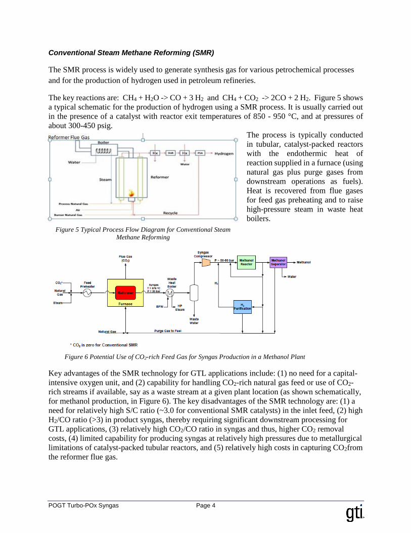
Conventional Steam Methane Reforming (SMR)
The SMR process is widely used to generate synthesis gas for various petrochemical processes
and for the production of hydrogen used in petroleum refineries.
The key reactions are: CH4 + H2O -> CO + 3 H2 and CH4 + CO2 -> 2CO + 2 H2. Figure 5 shows
a typical schematic for the production of hydrogen using a SMR process. It is usually carried out
in the presence of a catalyst with reactor exit temperatures of 850 - 950 °C, and at pressures of
about 300-450 psig.
The process is typically conducted
in tubular, catalyst-packed reactors
with the endothermic heat of
reaction supplied in a furnace (using
natural gas plus purge gases from
downstream operations as fuels).
Heat is recovered from flue gases
for feed gas preheating and to raise
high-pressure steam in waste heat
boilers.
Key advantages of the SMR technology for GTL applications include: (1) no need for a capital-
intensive oxygen unit, and (2) capability for handling CO2-rich natural gas feed or use of CO2-
rich streams if available, say as a waste stream at a given plant location (as shown schematically,
for methanol production, in Figure 6). The key disadvantages of the SMR technology are: (1) a
need for relatively high S/C ratio (~3.0 for conventional SMR catalysts) in the inlet feed, (2) high
H2/CO ratio (>3) in product syngas, thereby requiring significant downstream processing for
GTL applications, (3) relatively high CO2/CO ratio in syngas and thus, higher CO2 removal
costs, (4) limited capability for producing syngas at relatively high pressures due to metallurgical
limitations of catalyst-packed tubular reactors, and (5) relatively high costs in capturing CO2from
the reformer flue gas.
Figure 5 Typical Process Flow Diagram for Conventional Steam
Methane Reforming
Figure 6 Potential Use of CO2-rich Feed Gas for Syngas Production in a Methanol Plant

POGT Turbo-POx Syngas Page 5
Conventional Catalytic ATR (Autothermal Reformer)
Unlike non-catalytic partial oxidation reforming, “autothermal reforming” uses a catalyst to
reform the natural gas to syngas in the presence of oxygen plus steam. Due to the use of milder
operating conditions (exit temperatures of ~1,000 - 1,100 °C) and the use of relatively high S/C
molar ratio, the syngas is soot free. As shown in Figure 7, for a FT-GTL process, Haldor-Topsoe
(HTAS) has demonstrated commercially the production of syngas with a H2/CO ratio of ~2.0 by
using an S/C ratio of ~0.6 and by recycling a part of the CO2-rich Tail-gas from the FT section7,8.
Figure 7 Typical Process Flow Diagram for a Conventional Catalytic ATR Process for FT
A schematic of the HTAS ATR reactor and
key chemical reactions that occur in the
reactor are shown in Figure 88.
Haldor Topsoe ATR/GHR Integration to Reduce Cost for Syngas Production
One of the primary cost components in the
front-end of a POx or ATR-based GTL
plant is the air-separation unit (ASU).
Specific engineering improvements in
reducing oxygen usage will significantly reduce net costs for a GTL plant. According to HTAS,
use of a lower S/C ratio improves the syngas composition and reduces the extent of tail gas
recycle7. However, the use of a lower S/C ratio also reduces the margin to carbon formation in
the pre-reformer and to soot formation in the ATR reactor. HTAS is collaborating with Sasol Inc.
in demonstrating novel integrated ATR and HTER (Haldor Topsoe Exchange Reformer; also
referred to as GHR : Gas Heated Reformer) process options in reducing overall costs for syngas
generation in a FT process9. As shown in Figure 9, two different design options (namely, a
parallel arrangement and a series arrangement) are being evaluated for an optimum ATR/GHR
configuration.
Figure 8 A Schematic of the HTAS ATR Reactor

POGT Turbo-POx Syngas Page 6
Figure 9 Typical Flow Diagram for Haldor Topsoe ATR + GHR (Haldor Topsoe Gas Heated Reformer)
As shown in Table 1, according to HTAS7, the ATR/GHR options provide substantial cost
reductions compared to their stand-alone commercial ATR technology,
Table 1 Impact of Reduced S/C ratio on ATR and ATR/GHR Performance
Design Case ATR (Base) ATR (Advanced) @
Lower S/C
ATR with
Series GHR
S/C ratio 0.6 0.4 0.4/0.55
O2 Usage, Tonnes/bbl Produced
Index
100 92 81
Total LHV Efficiency Index 100 105 109
ASU CAPEX, $/bbl/day Index 100 83 74
SGP CAPEX, $/bbl/day Index 100 69 76
ASU + SGP CAPEX, $/bbl/day
Index
100 76 75
GTI’s PATENTED POGT CONCEPT FOR CO-PRODUCING SYNGAS PLUS ELECTRICTY FROM NATURAL GAS
With financial assistance from ARPA-E, GTI is currently collaborating with AR to further
develop GTI’s patented (US # 7,421,835-B2 and 8,268,896-B2) POGT (Partial Oxidation Gas
Turbine) concept for low-cost gas-based syngas generation using AR’s Turbo-POx10 technology
for various GTL and GTP (Gas-to-Products) processes. In a conventional POx/ATR or a SMR
technology, the hot syngas product from the SGP step is cooled to 35 - 40 °C in a typical WHB.
In the POGT concept, the hot syngas at ~1,090 - 1,320 °C and at ~500 - 1,500 psia from a partial
oxidation reactor would be cooled rapidly in less than ~ 6 milliseconds to about 1,100 °F (~593
°C) and ~150 - 200 psia using a turbo-expander to co-produce electricity and steam. In the AR’s
Turbo-POx option, where the AR non-catalytic POx technology is integrated with AR’s
“Reducing Turbo-Expander”, a patented (US # 6,565,312) “regenerative” cooling design for the
expander blades10, would be implemented. The S/C molar ratio in the AR POx reactor would
typically be ~0.2 - 0.3.

POGT Turbo-POx Syngas Page 7
Figure 10 GTI’s Patented POGT Syngas Generation Concept using AR’s Turbo-POx for GTL Applications
As shown in Figure 10, the syngas effluent from the expander will be further cooled to ~ 35 -
40 °C in a relatively small WHB to raise additional HP steam and to remove a major fraction of
the water in the syngas. The syngas would then be re-compressed to a higher pressure, depending
on the back-end GTL process. In Figure 10, the HTAS TIGAS technology5 is shown as the back-
end GTL option. A typical product slate in the ExxonMobil MTG type GTL process would be
~ 86 volume% zero-sulfur high-octane gasoline and ~14% LPG. The POGT concept can be
integrated with a variety of back-end process options including ExxonMobil MTG, Primus
STG+, and Velocys micro-channel FT process11.
AR Gas-based POx Development Reactor at GTI
As shown in Figure 11, under the ARPA-E program, AR and GTI
have been testing an AR POx combustor and the associated
injector at ~10 tonnes/day natural gas feed at GTI. A similar AR
reactor was used at GTI for AR’s dry-coal feed gasification
process using oxygen plus steam. It is anticipated that for a
commercial 1,000 barrels/day POGT capacity, there would be 12
closely coupled such POx combustor cans per expander. The GTI
testing involves a chamber pressure of 400 psia. This ARPA-E
project also includes: (1) design studies by AR for their turbo-
expander and (2) techno-economic assessment by GTI for two
GTL design cases, namely for a 1,000 bbl/day of FT
diesel/naphtha case, and the other for a 10,000 bbl/day MTG plant
producing gasoline plus LPG.
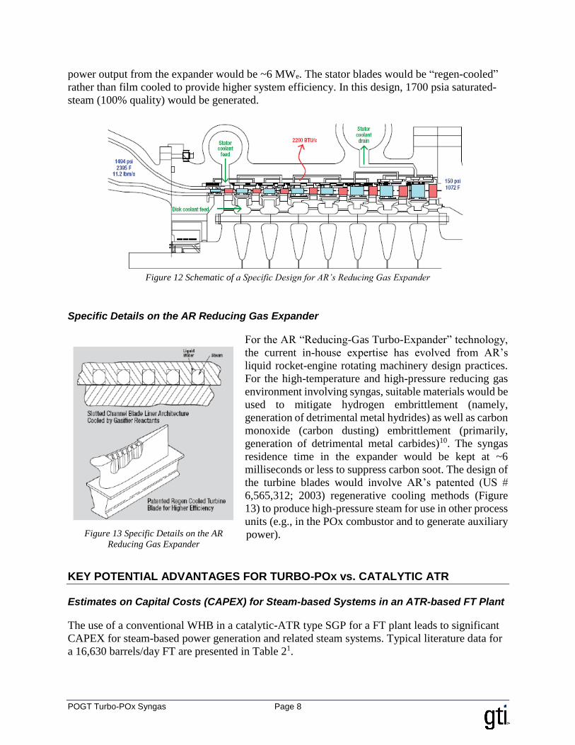
AR Expander Development
Under the ARPA-E program, AR is evaluating specific options for
the optimum design of a “Reducing Gas Expander” that can be
used in a 1,000 barrels/day GTL plant; the schematic of a generic
example for such an expander is shown in Figure 1210. As shown, this design refers to an inlet
syngas pressure of ~1500 psia with a temperature of ~2,395 °F (~1,313 °C); the outlet pressure
would be ~150 psia with a temperature of ~ 1,072 °F (~578 °C). For such a plant, the nominal
Figure 11 AR POx
Development Combustor at
GTI
POGT Turbo-POx Syngas Page 8
power output from the expander would be ~6 MWe. The stator blades would be “regen-cooled”
rather than film cooled to provide higher system efficiency. In this design, 1700 psia saturated-
steam (100% quality) would be generated.
Figure 12 Schematic of a Specific Design for AR’s Reducing Gas Expander
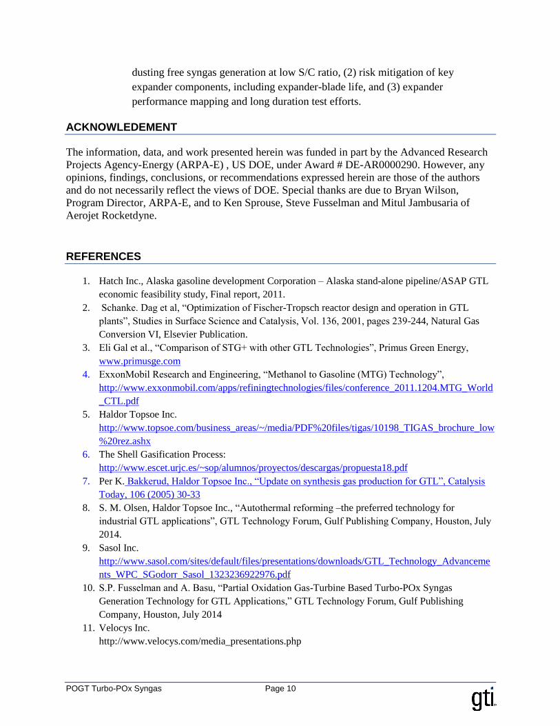
Specific Details on the AR Reducing Gas Expander
For the AR “Reducing-Gas Turbo-Expander” technology,
the current in-house expertise has evolved from AR’s
liquid rocket-engine rotating machinery design practices.
For the high-temperature and high-pressure reducing gas
environment involving syngas, suitable materials would be
used to mitigate hydrogen embrittlement (namely,
generation of detrimental metal hydrides) as well as carbon
monoxide (carbon dusting) embrittlement (primarily,
generation of detrimental metal carbides)10. The syngas
residence time in the expander would be kept at ~6
milliseconds or less to suppress carbon soot. The design of
the turbine blades would involve AR’s patented (US #
6,565,312; 2003) regenerative cooling methods (Figure
13) to produce high-pressure steam for use in other process
units (e.g., in the POx combustor and to generate auxiliary
power).
KEY POTENTIAL ADVANTAGES FOR TURBO-POx vs. CATALYTIC ATR
Estimates on Capital Costs (CAPEX) for Steam-based Systems in an ATR-based FT Plant
The use of a conventional WHB in a catalytic-ATR type SGP for a FT plant leads to significant
CAPEX for steam-based power generation and related steam systems. Typical literature data for
a 16,630 barrels/day FT are presented in Table 21.
Figure 13 Specific Details on the AR
Reducing Gas Expander

POGT Turbo-POx Syngas Page 9
Table 2 Specific Details on the AR Reducing Gas Expander
Comment
Gross power generation, MWe 140 Estimate by GTI
CAPEX, $Million
Catalytic ATR 162 Ref. 1
Steam-based power generation
systems
181 Ref. 1
Boiler feed water & steam systems 91 Ref 1
As shown in Table 2 Specific Details on the AR Reducing Gas Expander, the CAPEX for steam-
based power generation units plus the steam systems was estimated (by Hatch Inc.) at about $272
Million compared to $162 MM for the ATR itself. In the Turbo-POx case, about 60-70% of the
electricity would be generated by the expander itself; in addition, some high-pressure steam
would also be generated in the expander.
Key Potential Advantages for Turbo-POx over Conventional Catalytic ATR
For syngas generation in GTL applications, key potential advantages of the Turbo-POx concept
over conventional catalytic ATR processes would be:
The close-coupled compact design of the non-catalytic AR POx reactor and the expander
would be very suitable for shop fabrication and for small-scale modular GTL plants.
Unlike in a catalytic-ATR design, there is no need for a catalytic pre-reformer; this would
help reduce overall capital cost as well as operating costs (OPEX) savings related to the
pre-reformer catalyst. In addition, there would be significant reduction in OPEX as no
catalyst would be required for the AR POx reactor.
The usage of significantly lower S/C ratio (e.g., 0.2 vs. 0.6 for ATR) in a Turbo-POx
design would significantly reduce oxygen requirement as well as the extent of Tail-gas
recycle in a FT process which would lead to significant reductions in: (1) total volumes
for POx as well as for FT reactor units, (2) compression costs for Tail-gas recycle and (3)
total electric power need due to reduction in oxygen usage.
Significantly reduced capacities and lower CAPEX/OPEX costs for waste-heat boiler,
steam turbine power-generation unit and steam systems.
SUMMARY AND CONCLUSIONS
The AR/GTI Turbo-POx based GTL plants offer potential economic advantages in
relation to conventional POx and ATR GTL processes
The regen-cooled expander design needs further maturity to meet expander life
requirements in reducing syngas environment
o A 1,000 barrels/day integrated POx reactor/expander system needs to be
demonstrated at a brown-field site. Testing should include: (1) soot-free, metal-
POGT Turbo-POx Syngas Page 10
dusting free syngas generation at low S/C ratio, (2) risk mitigation of key
expander components, including expander-blade life, and (3) expander
performance mapping and long duration test efforts.
ACKNOWLEDEMENT
The information, data, and work presented herein was funded in part by the Advanced Research
Projects Agency-Energy (ARPA-E) , US DOE, under Award # DE-AR0000290. However, any
opinions, findings, conclusions, or recommendations expressed herein are those of the authors
and do not necessarily reflect the views of DOE. Special thanks are due to Bryan Wilson,
Program Director, ARPA-E, and to Ken Sprouse, Steve Fusselman and Mitul Jambusaria of
Aerojet Rocketdyne.
REFERENCES
1. Hatch Inc., Alaska gasoline development Corporation – Alaska stand-alone pipeline/ASAP GTL
economic feasibility study, Final report, 2011.
2. Schanke. Dag et al, “Optimization of Fischer-Tropsch reactor design and operation in GTL
plants”, Studies in Surface Science and Catalysis, Vol. 136, 2001, pages 239-244, Natural Gas
Conversion VI, Elsevier Publication.
3. Eli Gal et al., “Comparison of STG+ with other GTL Technologies”, Primus Green Energy,
www.primusge.com
4. ExxonMobil Research and Engineering, “Methanol to Gasoline (MTG) Technology”,
http://www.exxonmobil.com/apps/refiningtechnologies/files/conference_2011.1204.MTG_World
_CTL.pdf
5. Haldor Topsoe Inc.
http://www.topsoe.com/business_areas/~/media/PDF%20files/tigas/10198_TIGAS_brochure_low
%20rez.ashx
6. The Shell Gasification Process:
http://www.escet.urjc.es/~sop/alumnos/proyectos/descargas/propuesta18.pdf
7. Per K. Bakkerud, Haldor Topsoe Inc., “Update on synthesis gas production for GTL”, Catalysis
Today, 106 (2005) 30-33
8. S. M. Olsen, Haldor Topsoe Inc., “Autothermal reforming –the preferred technology for
industrial GTL applications”, GTL Technology Forum, Gulf Publishing Company, Houston, July
2014.
9. Sasol Inc.
http://www.sasol.com/sites/default/files/presentations/downloads/GTL_Technology_Advanceme
nts_WPC_SGodorr_Sasol_1323236922976.pdf
10. S.P. Fusselman and A. Basu, “Partial Oxidation Gas-Turbine Based Turbo-POx Syngas
Generation Technology for GTL Applications,” GTL Technology Forum, Gulf Publishing
Company, Houston, July 2014
11. Velocys Inc.
http://www.velocys.com/media_presentations.php