Part2: Cavities and Structures Modes in resonant cavity From a cavity to an accelerator Examples of...
32
Part2: Cavities and Structures • Modes in resonant cavity • From a cavity to an accelerator • Examples of structures JUAS 201 Linacs-JB.Lallement - JUAS 2015 1
-
Upload
bethanie-franklin -
Category
Documents
-
view
220 -
download
0
Transcript of Part2: Cavities and Structures Modes in resonant cavity From a cavity to an accelerator Examples of...
1
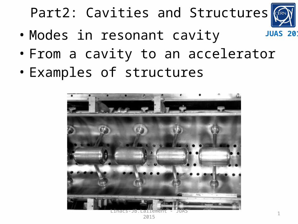
Part2: Cavities and Structures
• Modes in resonant cavity• From a cavity to an accelerator• Examples of structures
JUAS 2015
Linacs-JB.Lallement - JUAS 2015

2
Wave equationCavity modes
Maxwell equation for electromagnetics waves
• In free space the electromagnetic fieds are of the transverse electromagnetic, TEM type: Electric and magnetic field vectors are to each oher and to the direction of propagation !
• In a bounded medium (cavity) the solution of the equation must satisfy the boundary conditions:
Linacs-JB.Lallement - JUAS 2015
3
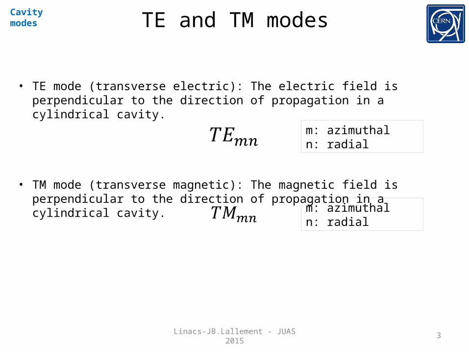
TE and TM modesCavity modes
• TE mode (transverse electric): The electric field is perpendicular to the direction of propagation in a cylindrical cavity.
• TM mode (transverse magnetic): The magnetic field is perpendicular to the direction of propagation in a cylindrical cavity.
m: azimuthaln: radial
m: azimuthaln: radial
Linacs-JB.Lallement - JUAS 2015
4
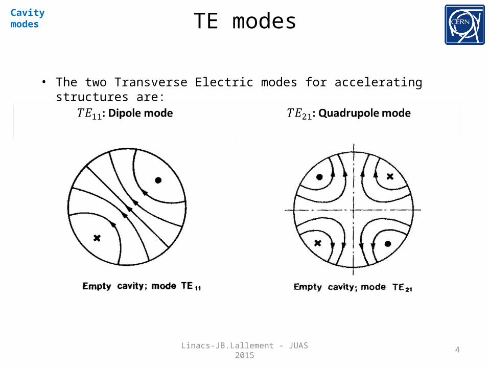
TE modesCavity modes
• The two Transverse Electric modes for accelerating structures are:
Linacs-JB.Lallement - JUAS 2015

5
TM modesCavity modes
• The most commonly used Transverse Magnetic mode for accelerating structures is:
Linacs-JB.Lallement - JUAS 2015

6
TM modesCavity modes
• The most commonly used for accelerating structures are the TM modes:
TM010 : f=352.2 MHz TM011 : f=548 MHz TM020 : f=952 MHzLinacs-JB.Lallement - JUAS 2015
7
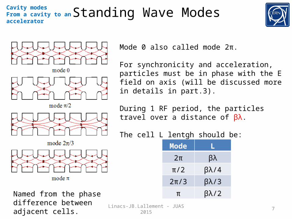
Standing Wave ModesCavity modesFrom a cavity to an accelerator
Mode 0 also called mode 2π.
For synchronicity and acceleration, particles must be in phase with the E field on axis (will be discussed more in details in part.3).
During 1 RF period, the particles travel over a distance of βλ.
The cell L lentgh should be:
Mode L
2π βλ
π/2 βλ/4
2π/3 βλ/3
π βλ/2Named from the phase difference between adjacent cells.
Linacs-JB.Lallement - JUAS 2015

8
Basic accelerating structuresBasic structures
• TE mode:• Radio Frequency Quadrupole: RFQ• Interdigital-H structure: IH
• TM mode:• Drift Tube Linac: DTL• Cavity Coupled DTL: CCDTL• PI Mode Structure: PIMS• Superconducting cavities
Linacs-JB.Lallement - JUAS 2015
9
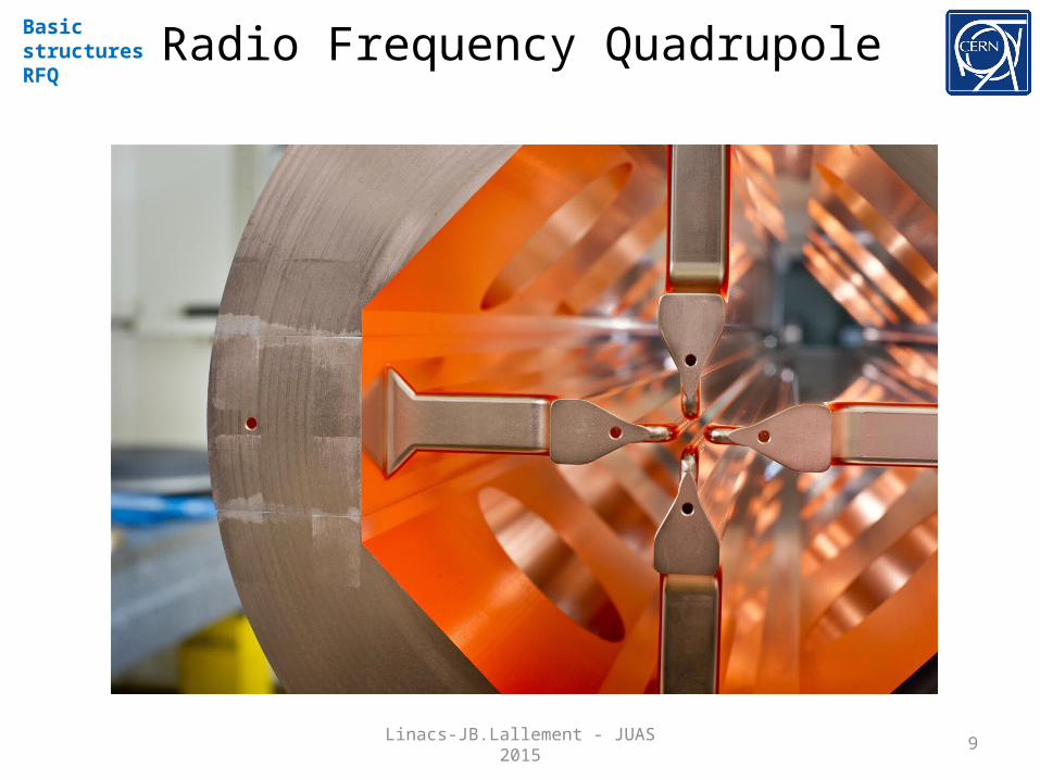
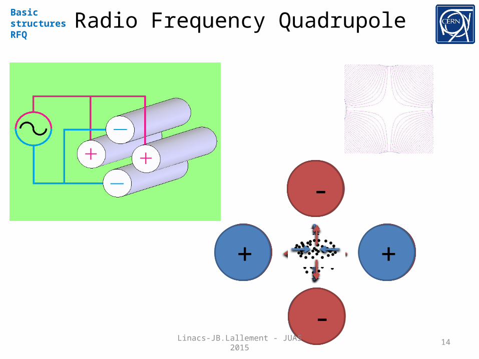
Radio Frequency QuadrupoleBasic structuresRFQ
Linacs-JB.Lallement - JUAS 2015

10
Radio Frequency QuadrupoleBasic structuresRFQ
Linacs-JB.Lallement - JUAS 2015

11
Radio Frequency QuadrupoleBasic structuresRFQ
Linacs-JB.Lallement - JUAS 2015
12
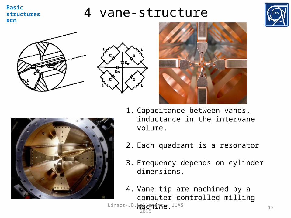
4 vane-structureBasic structuresRFQ
1. Capacitance between vanes, inductance in the intervane volume.
2. Each quadrant is a resonator
3. Frequency depends on cylinder dimensions.
4. Vane tip are machined by a computer controlled milling machine.
5. Need stabilization (problem of mixing with dipole mode TE11).Linacs-JB.Lallement - JUAS 2015
13
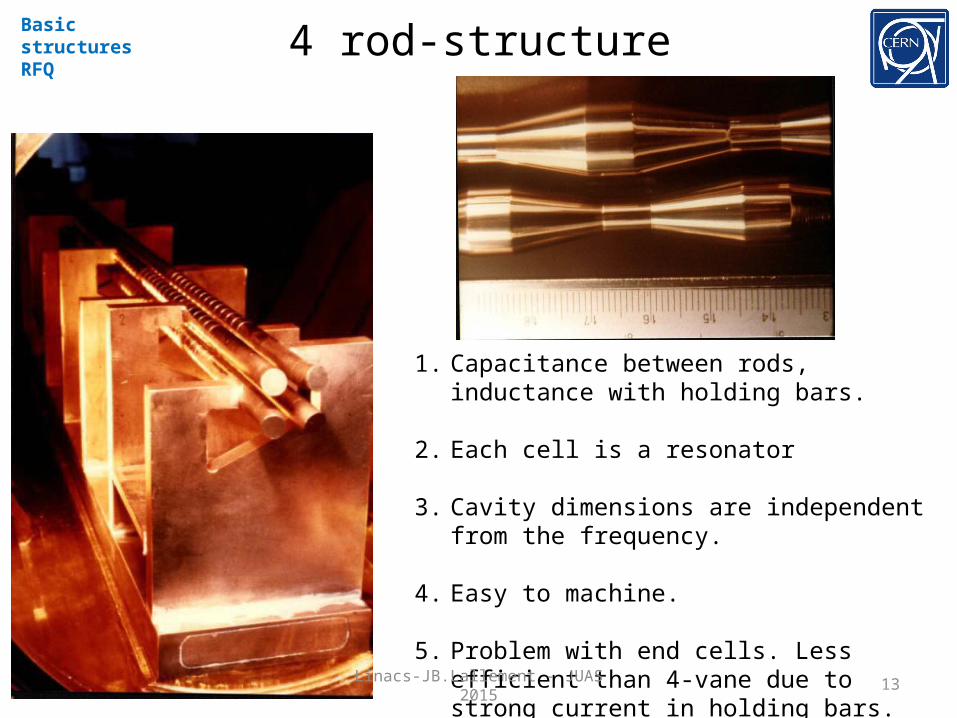
4 rod-structureBasic structuresRFQ
1. Capacitance between rods, inductance with holding bars.
2. Each cell is a resonator
3. Cavity dimensions are independent from the frequency.
4. Easy to machine.
5. Problem with end cells. Less efficient than 4-vane due to strong current in holding bars.Linacs-JB.Lallement - JUAS 2015
14
Radio Frequency QuadrupoleBasic structuresRFQ
-
+
-
+-
+ +
-
-
+
-
+-
+ +
-
-
+
-
+-
+ +
-Linacs-JB.Lallement - JUAS 2015
15
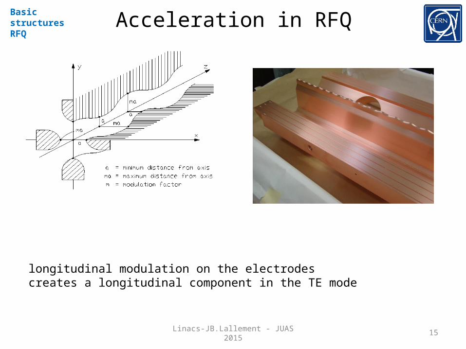
Acceleration in RFQBasic structuresRFQ
longitudinal modulation on the electrodes creates a longitudinal component in the TE mode
Linacs-JB.Lallement - JUAS 2015
16
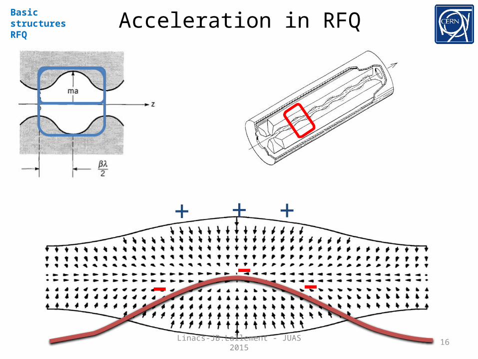
Acceleration in RFQBasic structuresRFQ
-
+ ++
- -Linacs-JB.Lallement - JUAS 2015
17
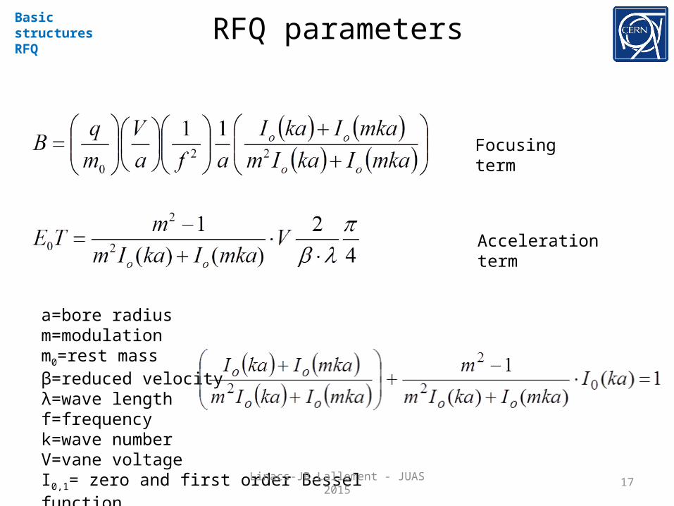
RFQ parametersBasic structuresRFQ
Focusing term
Acceleration term
a=bore radiusm=modulationm0=rest massβ=reduced velocityλ=wave lengthf=frequencyk=wave numberV=vane voltageI0,1= zero and first order Bessel functionLinacs-JB.Lallement - JUAS 2015

18
RFQBasic structuresRFQ
• The resonating mode of the cavity is a focusing mode• Alternating the voltage on the electrodes produces an alternating
focusing channel• A longitudinal modulation of the electrodes produces a field in the
direction of propagation of the beam which bunches and accelerates the beam
• Both the focusing as well as the bunching and acceleration are performed by the RF field
• The RFQ is the only linear accelerator that can accept a low energy CONTINOUS beam of particles
• 1970 Kapchinskij and Teplyakov propose the idea of the radiofrequency quadrupole ( I. M. Kapchinskii and V. A. Teplvakov, Prib.Tekh. Eksp. No. 2, 19 (1970))
AccelerationBunchingTransverse focusing
Linacs-JB.Lallement - JUAS 2015
19
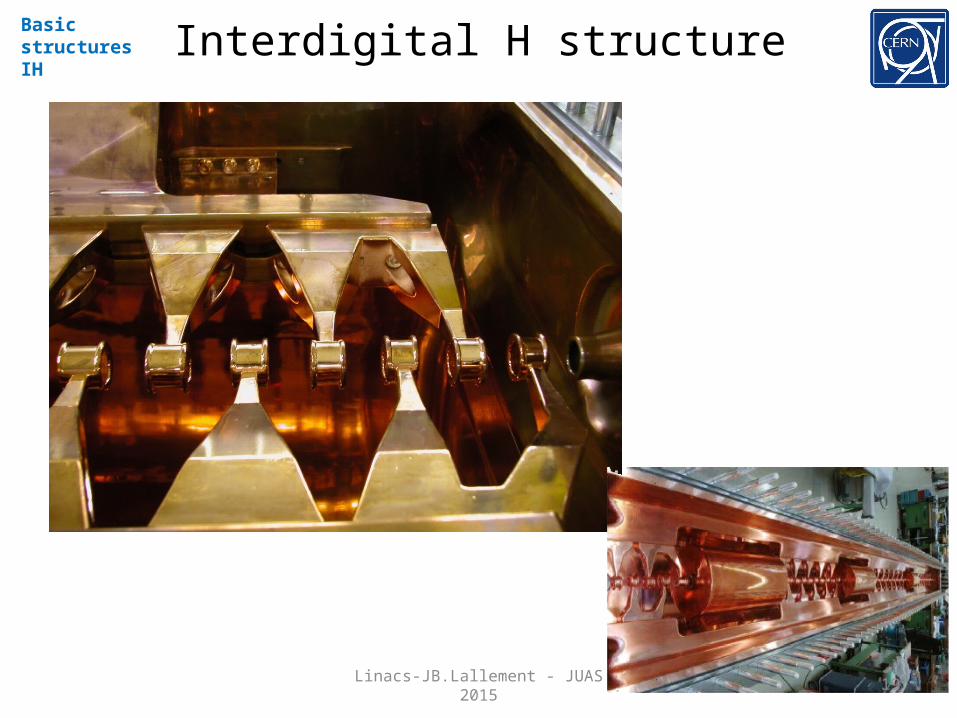
Interdigital H structureBasic structuresIH
Linacs-JB.Lallement - JUAS 2015
20
Interdigital H structureBasic structuresIH
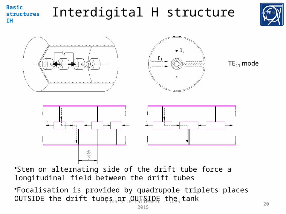
•Stem on alternating side of the drift tube force a longitudinal field between the drift tubes
•Focalisation is provided by quadrupole triplets places OUTSIDE the drift tubes or OUTSIDE the tank
Linacs-JB.Lallement - JUAS 2015

21
Interdigital H structureBasic structuresIH
• very good shunt impedance in the low beta region (( 0.02 to 0.08 ) and low frequency (up to 200MHz)
• not for high intensity beam due to long focusing period
• ideal for low beta heavy ion acceleration
Linacs-JB.Lallement - JUAS 2015
22
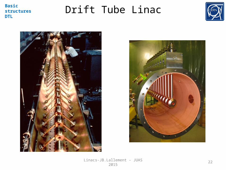
Drift Tube LinacBasic structuresDTL
Linacs-JB.Lallement - JUAS 2015

23
Drift Tube LinacBasic structuresDTL
Linacs-JB.Lallement - JUAS 2015
Tutorial !
24
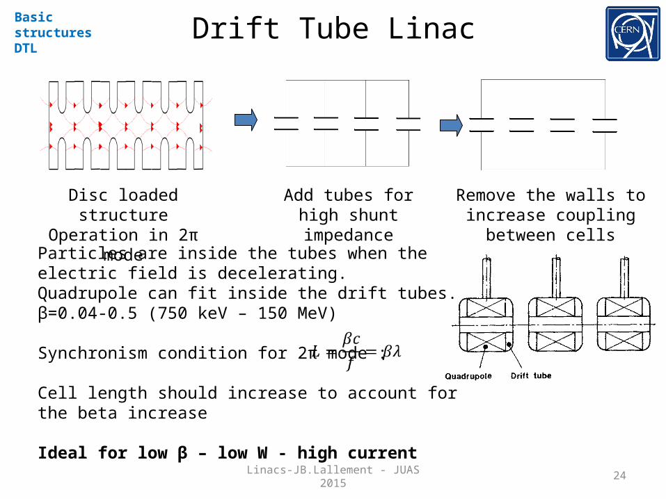
Drift Tube LinacBasic structuresDTL
Disc loaded structureOperation in 2π mode
Add tubes for high shunt impedance
Remove the walls to increase coupling between cells
Particles are inside the tubes when the electric field is decelerating.Quadrupole can fit inside the drift tubes.β=0.04-0.5 (750 keV – 150 MeV)
Synchronism condition for 2π mode :
Cell length should increase to account for the beta increase
Ideal for low β – low W - high current
Linacs-JB.Lallement - JUAS 2015

25
Drift Tube LinacBasic structuresDTL
CERN Linac2 DTL
CERN Linac4 DTL
Linacs-JB.Lallement - JUAS 2015

26
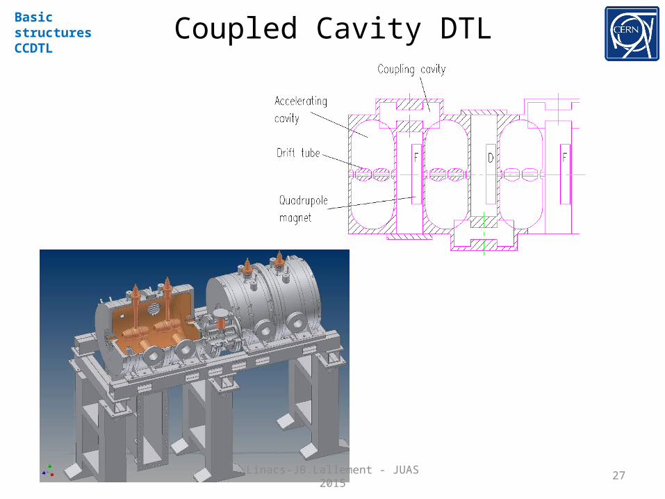
Coupled Cavity DTLBasic structuresCCDTL
Linacs-JB.Lallement - JUAS 2015
27
Coupled Cavity DTLBasic structuresCCDTL
Linacs-JB.Lallement - JUAS 2015
28
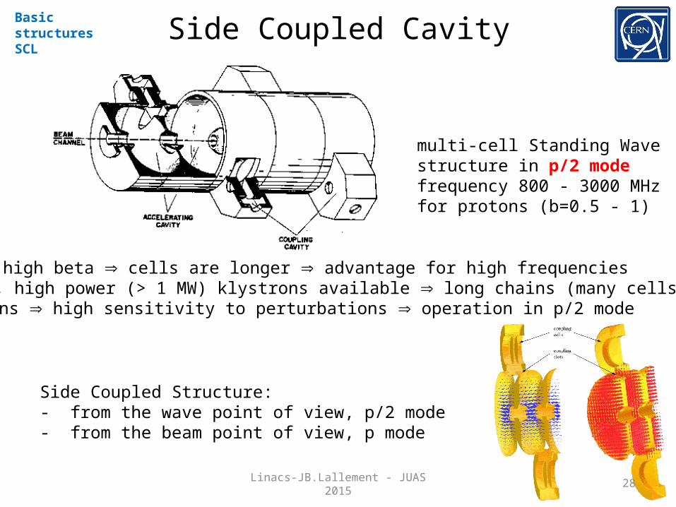
Side Coupled CavityBasic structuresSCL
multi-cell Standing Wave structure in p/2 modefrequency 800 - 3000 MHzfor protons (b=0.5 - 1)
Rationale: high beta cells are longer advantage for high frequencies• at high f, high power (> 1 MW) klystrons available long chains (many cells)• long chains high sensitivity to perturbations operation in p/2 mode
Side Coupled Structure:- from the wave point of view, p/2 mode- from the beam point of view, p mode
Linacs-JB.Lallement - JUAS 2015
29
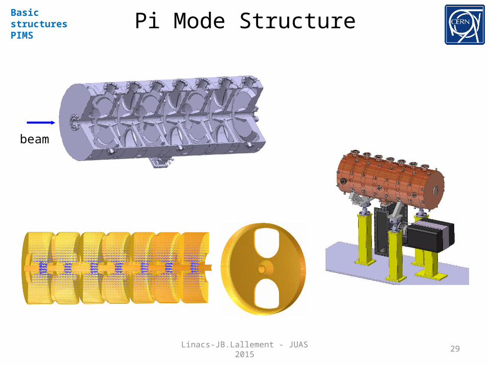
Pi Mode StructureBasic structuresPIMS
beam
Linacs-JB.Lallement - JUAS 2015

30
Superconducting cavitiesSome examples
Basic structuresSC cavities
Multi gap cavities (elliptical)Operate in π modeβ>0.5-0.7350-700 MHz (protons)0.35-3 GHz (electrons)
Other SC cavities (spoke, HWR, QWR)β>0.1From 1 to 4 gaps.Can be individually phased.Space for transverse focusing in betweenIdeal for low β - CW proton linacs.
Linacs-JB.Lallement - JUAS 2015
31
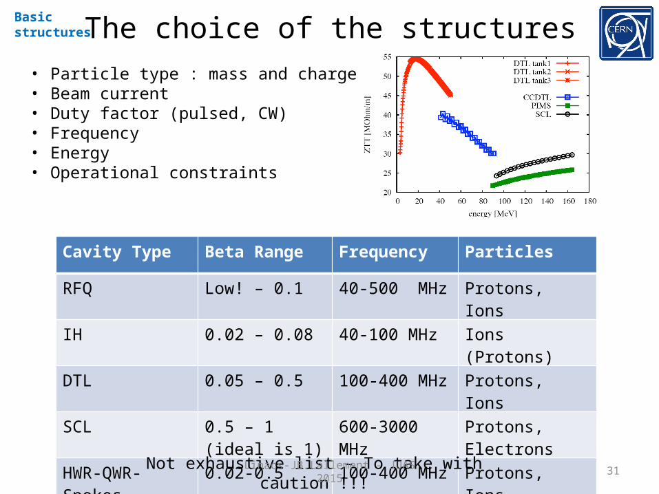
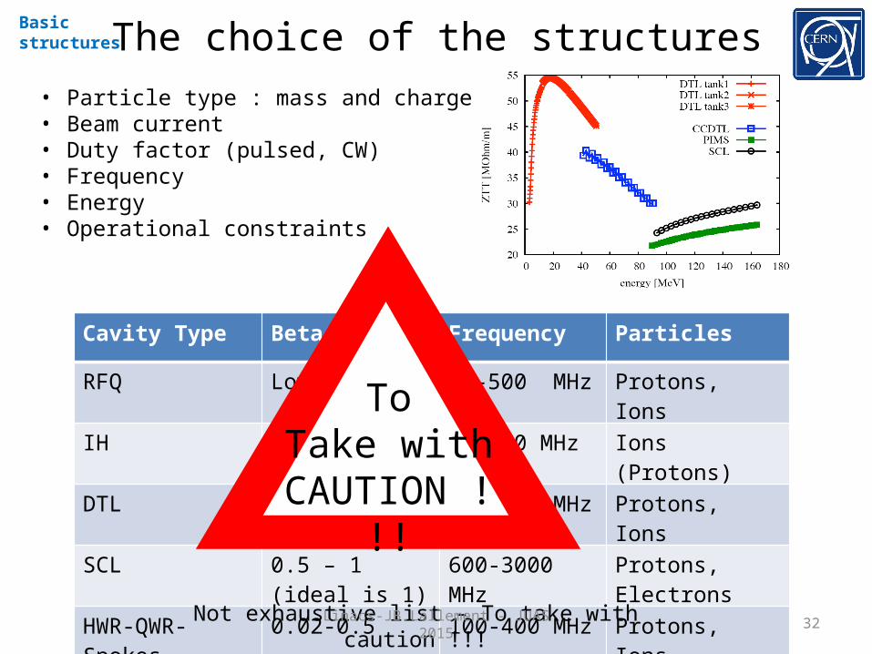
The choice of the structuresBasic structures
• Particle type : mass and charge• Beam current• Duty factor (pulsed, CW)• Frequency• Energy• Operational constraints
Cavity Type Beta Range Frequency Particles
RFQ Low! – 0.1 40-500 MHz Protons, Ions
IH 0.02 – 0.08 40-100 MHz Ions (Protons)
DTL 0.05 – 0.5 100-400 MHz Protons, Ions
SCL 0.5 – 1 (ideal is 1) 600-3000 MHz Protons, Electrons
HWR-QWR-Spokes 0.02-0.5 100-400 MHz Protons, Ions
Elliptical > 0.5-0.7 350 – 3000 MHz Protons, Electrons
Not exhaustive list – To take with caution !!!Linacs-JB.Lallement - JUAS 2015
32
The choice of the structuresBasic structures
• Particle type : mass and charge• Beam current• Duty factor (pulsed, CW)• Frequency• Energy• Operational constraints
Cavity Type Beta Range Frequency Particles
RFQ Low! – 0.1 40-500 MHz Protons, Ions
IH 0.02 – 0.08 40-100 MHz Ions (Protons)
DTL 0.05 – 0.5 100-400 MHz Protons, Ions
SCL 0.5 – 1 (ideal is 1) 600-3000 MHz Protons, Electrons
HWR-QWR-Spokes 0.02-0.5 100-400 MHz Protons, Ions
Elliptical > 0.5-0.7 350 – 3000 MHz Protons, Electrons
Not exhaustive list – To take with caution !!!
ToTake with
CAUTION !!!
Linacs-JB.Lallement - JUAS 2015