Part V: Stylization of Line Drawings - Graphics...
55
1 Part V: Stylization of Line Drawings Adam Finkelstein Line Drawings from 3D Models SIGGRAPH 2005 Course Notes Part V: Stylization of Line Drawings Adam Finkelstein Line Drawings from 3D Models SIGGRAPH 2005 Course Notes
Transcript of Part V: Stylization of Line Drawings - Graphics...

1
Part V:Stylization of Line Drawings
Adam Finkelstein
Line Drawings from 3D ModelsSIGGRAPH 2005 Course Notes
Part V:Stylization of Line Drawings
Adam Finkelstein
Line Drawings from 3D ModelsSIGGRAPH 2005 Course Notes
2
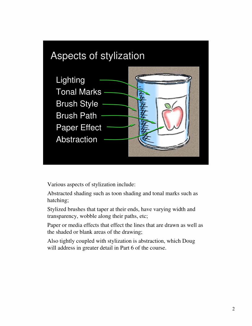
Aspects of stylization
Lighting
Tonal Marks
Brush Style
Brush Path
Paper Effect
Abstraction
Various aspects of stylization include:
Abstracted shading such as toon shading and tonal marks such as
hatching;
Stylized brushes that taper at their ends, have varying width and
transparency, wobble along their paths, etc;
Paper or media effects that effect the lines that are drawn as well as
the shaded or blank areas of the drawing;
Also tightly coupled with stylization is abstraction, which Doug
will address in greater detail in Part 6 of the course.

3
1. Stylized lines
2. Visibility of lines in 3D
3. How to specify stylization
4. Temporal coherence for stylized lines
Overview of this section
Here is an overview of this section.

4
1. Stylized lines
2. Visibility of lines in 3D
3. How to specify stylization
4. Temporal coherence for stylized lines
Overview of this section
We’ll start by talking about stylized lines.

5
Stylized strokes
[Hsu 94] [Curtis 98][Curtis 98]
Strokes are the fundamental primitive of a line drawing. Each
individual stroke has many qualities in addition to its path -- it can
have varying thickness, wiggliness, opacity, and texture, not to
mention its time-dependent nature. These qualities give line
drawings much of their character or charm, and can convey feeling
as well.

6
Many Forms of Stylization
[Kalnins 02]
Here are a few more examples of the range of effects possible,
showing up close what the brush might look like.
Lines can be made to wiggled with offsets, textured with watercolor
strokes, broken into dashes for mechanical drawings, and even
geometric effects can even be suggested, such as the thorny
stylization used on silhouettes of this cactus.

7
Skeletal strokes [Hsu 94]
In 1994, Hsu presented a system called Skeletal Strokes that
described how such qualities could be applied to CG lines. Indeed
many of these features are now standard fare in commercial
programs such as Adobe Illustrator.
8
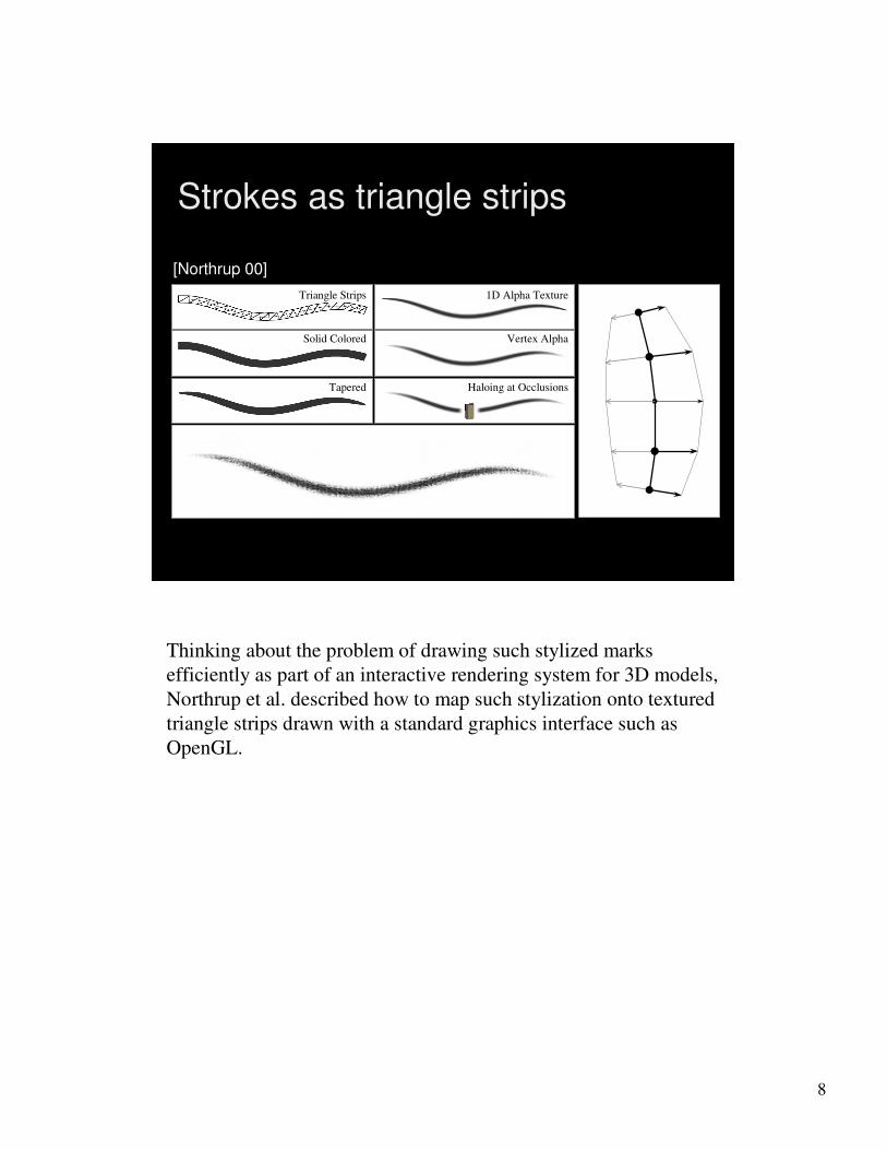
Strokes as triangle strips
1D Alpha Texture1D Alpha Texture
Vertex AlphaVertex Alpha
Haloing at OcclusionsHaloing at Occlusions
Solid ColoredSolid Colored
TaperedTapered
TriangleTriangle StripsStrips
[Northrup 00]
Thinking about the problem of drawing such stylized marks
efficiently as part of an interactive rendering system for 3D models,
Northrup et al. described how to map such stylization onto textured
triangle strips drawn with a standard graphics interface such as
OpenGL.
9
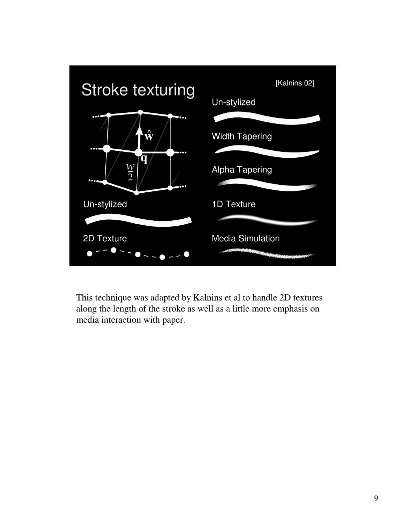
Stroke texturingUn-stylized
Width Tapering
Alpha Tapering
1D Texture
Media Simulation
Un-stylized
2D Texture
[Kalnins 02]
This technique was adapted by Kalnins et al to handle 2D textures
along the length of the stroke as well as a little more emphasis on
media interaction with paper.

10
Brush Style
Per stroke:
• Color
• Width profile
• Alpha profile
• Paper
• etc.
[Kalnins 02]
The lines can thus be drawn with very stylized brushes that
simulate the look of real media, at interactive frame rates.

11
1. Stylized lines
2. Visibility of lines in 3D
3. How to specify stylization
4. Temporal coherence for stylized lines
Overview of this section
The next question to address is how do we know which lines
extracted from a 3D model are visible?

12
• Interactivity (ray casting is expensive)
• Thick, wobbly lines (z-buffer won’t work)
• Silhouettes are at the visibility threshold
Visibility challenges
[Kalnins 02]
There are a number of challenges for computing visibility. Of
course it is possible to fire a ray from many points each line to the
viewer and see if it intersects anything along the way. However,
that strategy is expensive, meaning it won’t support interactive
applications for even moderately complex scenes. For interactivity,
why not just use the z-buffer? Well it turns out that if you draw the
model and also thick, wobbly lines in 3D, then the z-buffer
algorithm will chop the lines in ugly ways where they happen to
penetrate the model. Finally, a particular challenge for silhouette
lines is that by definition they exist right at the boundary between
visible and invisible parts of the model, making many visibility
algorithms naturally unstable at such points.

13
Visibility strategies
Hardware methods: minimal stylistic control
[Rossignac 92, Gooch 99, Raskar 01]
Ray casting may be accelerated by 3D/2D
analysis [Appel 67, Markosian 97]
Item buffer gives image-space precision
[Northrup00, Kalnins03]
Three general strategies have been used for visibility of lines. First,
there are hardware-based methods that cause visible -- or invisible -
- silhouette lines to appear without explicitly searching for them on
the model. Such methods are fast, but admit only minimal control
over the stylization of the lines they reveal. Second, while ray
casting can be slow, analysis of the shapes involved can reduce the
number of rays cast. Third, a hybrid method based on an item
buffer can compute visibility with image space precision. I’ll go
into a little more detail on these last two strategies.
14
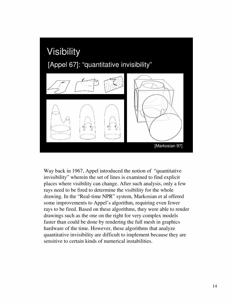
Visibility
[Markosian 97][Markosian 97]
[Appel 67]: “quantitative invisibility”
Way back in 1967, Appel introduced the notion of “quantitative
invisibility” wherein the set of lines is examined to find explicit
places where visibility can change. After such analysis, only a few
rays need to be fired to determine the visibility for the whole
drawing. In the “Real-time NPR” system, Markosian et al offered
some improvements to Appel’s algorithm, requiring even fewer
rays to be fired. Based on these algorithms, they were able to render
drawings such as the one on the right for very complex models
faster than could be done by rendering the full mesh in graphics
hardware of the time. However, these algorithms that analyze
quantitative invisibility are difficult to implement because they are
sensitive to certain kinds of numerical instabilities.
15
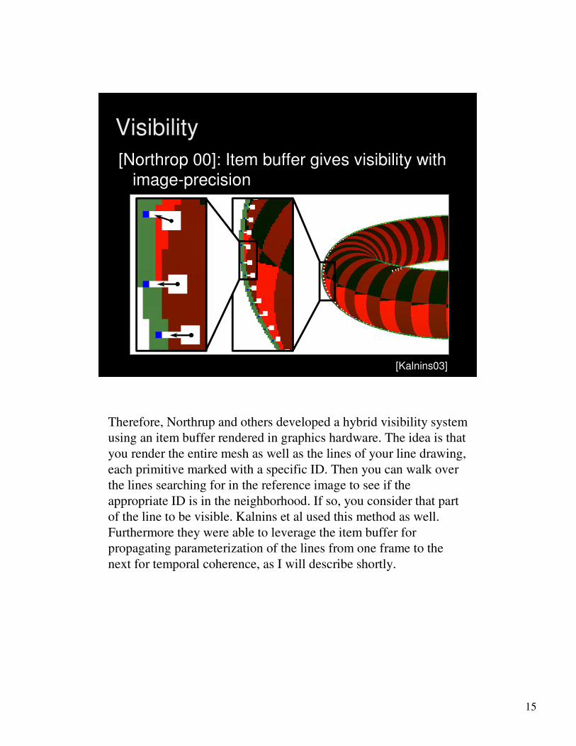
Visibility
[Kalnins03][Kalnins03]
[Northrop 00]: Item buffer gives visibility with
image-precision
Therefore, Northrup and others developed a hybrid visibility system
using an item buffer rendered in graphics hardware. The idea is that
you render the entire mesh as well as the lines of your line drawing,
each primitive marked with a specific ID. Then you can walk over
the lines searching for in the reference image to see if the
appropriate ID is in the neighborhood. If so, you consider that part
of the line to be visible. Kalnins et al used this method as well.
Furthermore they were able to leverage the item buffer for
propagating parameterization of the lines from one frame to the
next for temporal coherence, as I will describe shortly.
16
1. Stylized lines
2. Visibility of lines in 3D
3. How to specify stylization
4. Temporal coherence for stylized lines
Overview of this section
But first, let me discuss the question, how can an artist specify what
kind of stylization he would like for a model?

17
WYSIWYG NPR:Drawing Strokes Directly on 3D Models
WYSIWYG NPR:Drawing Strokes Directly on 3D Models
[Kalnins 02]
In 2002 my student Rob Kalnins and others presented a system
called WYSIWYG NPR, which stands for “What you see is what
you get … non-photorealistic rendering.”
The basic idea is that an artist should be able to draw right onto the
3D scene how he would like it to looks.
18
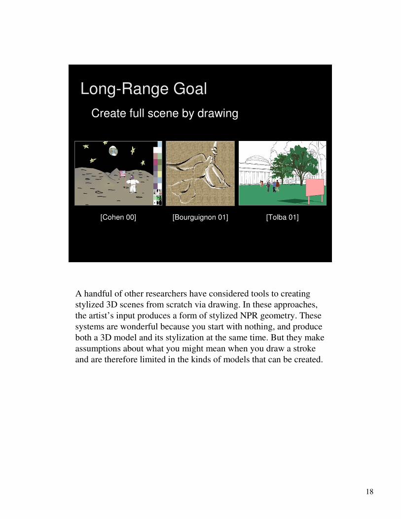
Long-Range Goal
[Tolba 01][Cohen 00] [Bourguignon 01]
Create full scene by drawing
A handful of other researchers have considered tools to creating
stylized 3D scenes from scratch via drawing. In these approaches,
the artist’s input produces a form of stylized NPR geometry. These
systems are wonderful because you start with nothing, and produce
both a 3D model and its stylization at the same time. But they make
assumptions about what you might mean when you draw a stroke
and are therefore limited in the kinds of models that can be created.

19
Annotating geometry
WYSIWYG Painting [Hanrahan 90]
In this sense the WYSIWYG NPR system more like that of
Hanrahan and Haeberli in which you start with a model and draw
directly on it. However, in Hanrahan’s system they were making
textures for the model, rather than thinking about annotating a
model with an NPR rendering style.

20
WYSIWYG NPR
• Ensure coherent animation
• Retain style in new views
• Draw into 3D scene
Here’s how the WYSIWYG NPR system works. The designer
begins by importing some existing 3D geometry like this tea cup
mesh. He then describes its stylized appearance annotating the
objects with stylized strokes drawn directly into the scene. When
the user moves to new camera positions, the system automatically
retains these stylizations. Furthermore, under animation, the system
also ensures that the stylizations *evolve* in a coherent fashion.

21
Aesthetic Flexibility
We have found that the payoff in aesthetic flexibility is immediate.
Even with a relatively small toolbox of effects that describe shortly
by simply permitting the designer to express the stylization via
hands-on means…

22
Aesthetic Flexibility
…a wide range of diverse aesthetics can be achieved. All of these
results were produced by annotating the same 3D tea cup mesh
from the previous slide.

23
WYSIWYG NPR (video)
The following video clip shows the kind of interface presented to
the artist.

24
Overview of Components
Base Coat
Brush Style
Paper Effect
Detail Marks
Tonal Marks
Outlines
The WYSIWYG NPR system provides a bunch of different tools to
produce a combined effect.
25
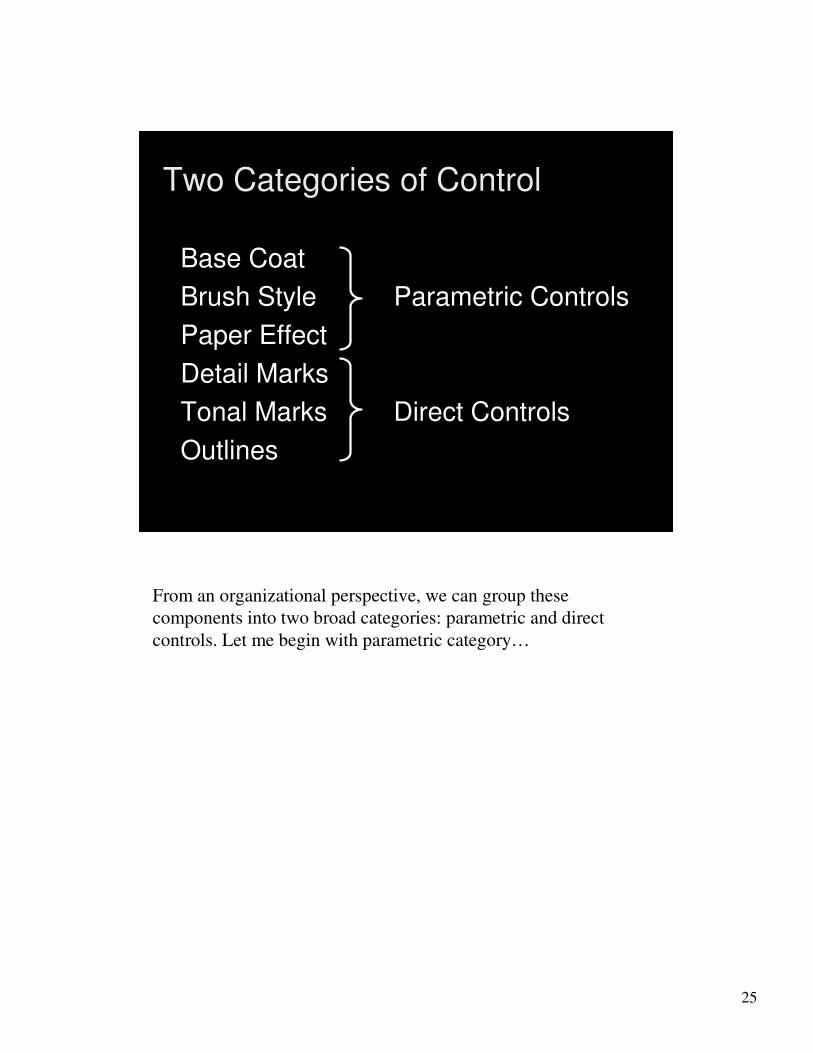
Two Categories of Control
Base Coat
Brush Style Parametric Controls
Paper Effect
Detail Marks
Tonal Marks Direct Controls
Outlines
From an organizational perspective, we can group these
components into two broad categories: parametric and direct
controls. Let me begin with parametric category…

26
Parametric Controls
Base Coat
Brush Style
Paper Effect
Detail Marks
Tonal Marks
Outlines
Parametric controls are rendering options tuned by sliders, or
checkboxes, for instance to adjust parameters like colors for
shaders, widths for brush styles, and textures for paper and media
simulations. Controls like these are common to much of the
previous work in NPR, and indeed our system also employed these
sorts of components.
Though necessary, I won’t really focus on these tools today.

27
Direct Controls
Base Coat
Brush Style
Paper Effect
Detail Marks
Tonal Marks
Outlines
Instead, I’ll focus on the second category -- direct controls – which
take their input via a more natural means, such as a tablet. These
controls allow the artist to influence the look of the scene by
sketching strokes directly into it.
28
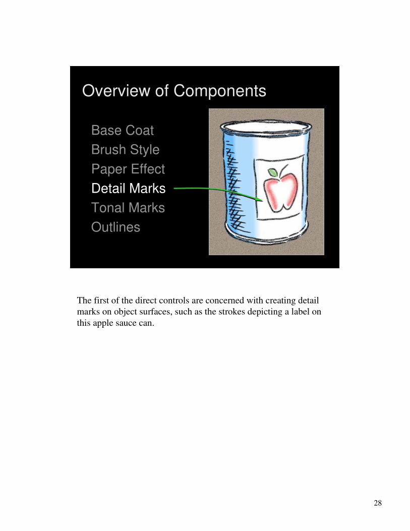
Overview of Components
Base Coat
Brush Style
Paper Effect
Detail Marks
Tonal Marks
Outlines
The first of the direct controls are concerned with creating detail
marks on object surfaces, such as the strokes depicting a label on
this apple sauce can.

29
Detail Marks
Direct control:Direct control:
•• Draw on surfaceDraw on surface
•• Generate strokes Generate strokes
For magnified or oblique views:For magnified or oblique views:
•• No blurring or aliasingNo blurring or aliasing
•• Explicit control of stroke widthExplicit control of stroke width
… unlike texture maps… unlike texture maps
To create detail marks, the user simply selects a brush style, and
sketches features onto the mesh. This has the effect of defining
stroke paths embedded in the 3D surface. As described earlier, each
path is rendered using a stroke primitive based on triangle strips.
Note that under magnified or oblique views, this approach differs
from texture maps into two ways. First, there are no blurring or
aliasing artifacts, because we render these paths using a stroke
primitive, and second, we have explicit control over stroke width.
30
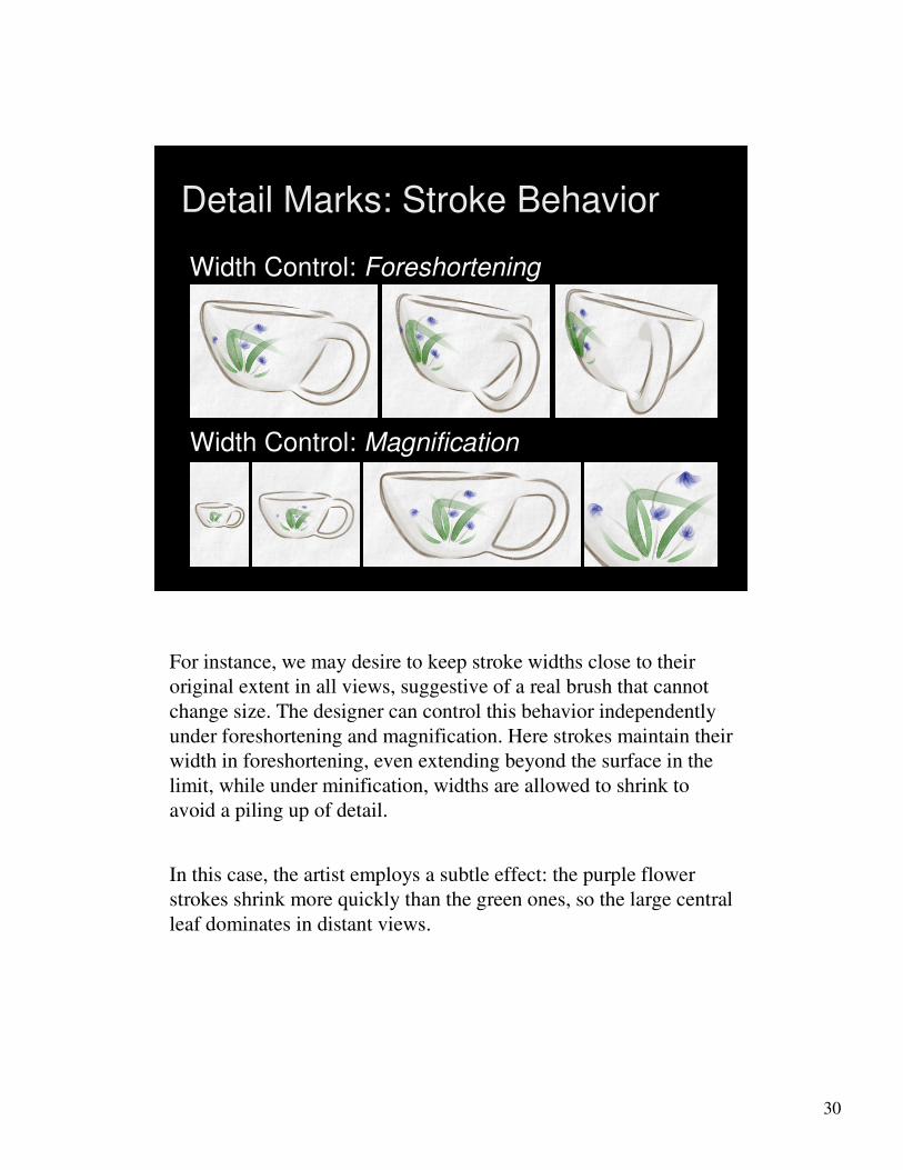
Detail Marks: Stroke Behavior
Width Control: Foreshortening
Width Control: Magnification
For instance, we may desire to keep stroke widths close to their
original extent in all views, suggestive of a real brush that cannot
change size. The designer can control this behavior independently
under foreshortening and magnification. Here strokes maintain their
width in foreshortening, even extending beyond the surface in the
limit, while under minification, widths are allowed to shrink to
avoid a piling up of detail.
In this case, the artist employs a subtle effect: the purple flower
strokes shrink more quickly than the green ones, so the large central
leaf dominates in distant views.

31
Detail Marks: Flexibility
Labels
Decals
Line DrawingsPainterly Effects
The designer can achieve a wide range of effect with this straight
forward tool. A few strokes can depict labels and decals as in the
upper images, while many wide stroke can create rich painterly
effects … and many narrow strokes can lead to detailed line
drawings. I’ll show several of these scenes in animation in a little
while.

32
Overview of Components
Base Coat
Brush Style
Paper Effect
Detail Marks
Tonal Marks
Outlines
The next direct effect is hatching. Much like decals, hatching is
drawn directly on the surface in the location and style desired by
the artist. Because these elements are not necessary for sparse line
drawings and because of time limitations…

33
Overview of Components
Base Coat
Brush Style
Paper Effect
Detail Marks
Tonal Marks
Outlines
…I’m going to push on to talk about outlines.
34
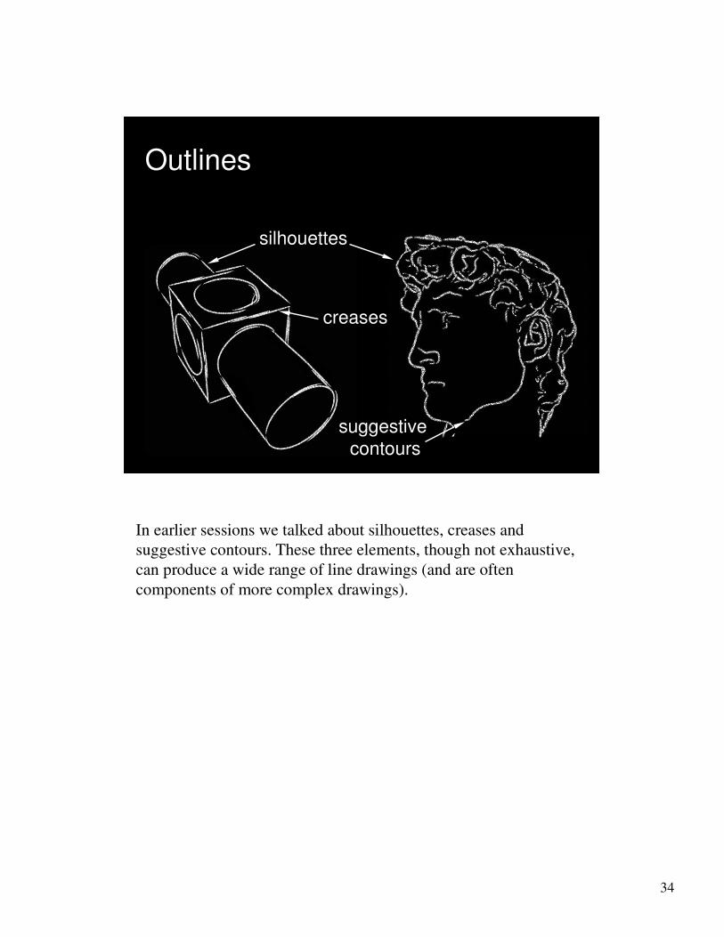
Outlines
suggestive
contours
creases
silhouettes
In earlier sessions we talked about silhouettes, creases and
suggestive contours. These three elements, though not exhaustive,
can produce a wide range of line drawings (and are often
components of more complex drawings).
35
(VIDEO)
Outlines
Let me show you a video of outline stylization in action.
36
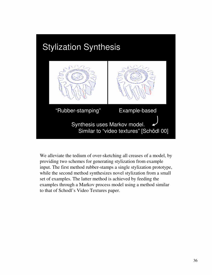
Stylization Synthesis
“Rubber“Rubber--stamping”stamping” ExampleExample--basedbased
Synthesis uses Markov model.Synthesis uses Markov model.
Similar to “video textures” [Similar to “video textures” [SchSchöödl dl 00]00]
We alleviate the tedium of over-sketching all creases of a model, by
providing two schemes for generating stylization from example
input. The first method rubber-stamps a single stylization prototype,
while the second method synthesizes novel stylization from a small
set of examples. The latter method is achieved by feeding the
examples through a Markov process model using a method similar
to that of Schodl’s Video Textures paper.

37
Outlines: Stylization
Non-Stylized
• Simple (GL_LINE)
• Easy to animate
Stylized
• Rich, flexible styles
• Challenge to animate
Stylizing the outlines of a model presents a particular challenge for
temporal coherence.
On the left, we show the mechanical part with no stylization yet
applied to its lines this rendering scheme can be easily implemented
in graphics hardware, but it also has the added advantage of being
easy to animate because there are no stylized features to keep track
of over time.
On the right, we show the same mesh rendered with stylized lines.
Such stylization can lead to a wide range of rich aesthetics, but this
comes at the cost of additional challenges during animation, since
we’ll have to keep track of the salient features of the stylization
over time.
38
1. Stylized lines
2. Visibility of lines in 3D
3. How to specify stylization
4. Temporal coherence for stylized lines
Overview of this section
So the last part of this section addresses the challenge of providing
temporal coherence for such lines.

39
Many Forms of Stylization
Just as a reminder, we’re dealing with a variety of styles of lines,
and we’d like their fine-scale detail to be coherent from one frame
to the next.
40
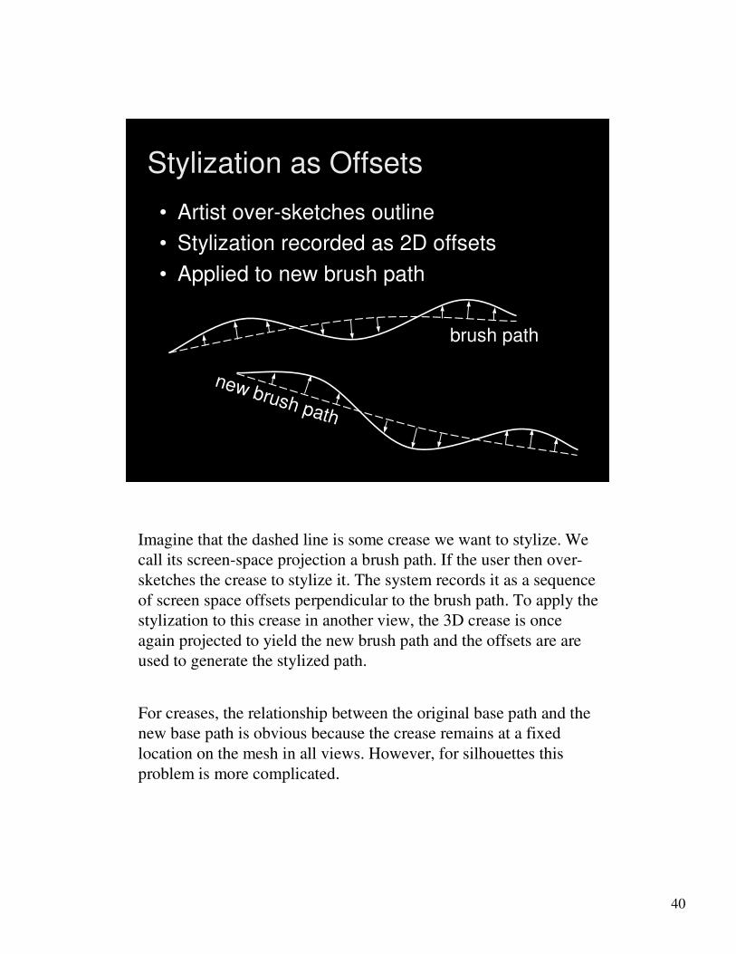
Stylization as Offsets
•• Artist overArtist over--sketches outlinesketches outline
•• Stylization recorded as 2D offsetsStylization recorded as 2D offsets
•• Applied to new brush pathApplied to new brush path
brush pathbrush path
new brush path
new brush path
Imagine that the dashed line is some crease we want to stylize. We
call its screen-space projection a brush path. If the user then over-
sketches the crease to stylize it. The system records it as a sequence
of screen space offsets perpendicular to the brush path. To apply the
stylization to this crease in another view, the 3D crease is once
again projected to yield the new brush path and the offsets are are
used to generate the stylized path.
For creases, the relationship between the original base path and the
new base path is obvious because the crease remains at a fixed
location on the mesh in all views. However, for silhouettes this
problem is more complicated.

41
mesh
visible paths
silhouettes
strokes3. Rendering
1. Extraction
2. Visibility
Stylized Silhouette Pipeline
To see why, we must consider the silhouette rendering pipeline.
Beginning with the triangle mesh…

42
mesh
visible paths
silhouettes
strokes3. Rendering
1. Extraction
2. Visibility
Stylized Silhouette Pipeline
The first step is to extract the silhouette contours from the
underlying geometry. Szymon discussed this problem in an earlier
session.

43
mesh
visible paths
silhouettes
strokes3. Rendering
1. Extraction
2. Visibility
Stylized Silhouette Pipeline
The second stage is to compute visibility, as I discussed moments
ago.

44
mesh
visible paths
silhouettes
strokes3. Rendering
• Re-mapping artist’s stylization
1. Extraction
2. Visibility
Stylized Silhouette Pipeline
And the final stage is to render these visible paths using the
stylization provided by the artist.

45
Coherence?
Maintaining temporal coherence of these effect is challenging. To
illustrate this I’ll show you an animation of this octopus -- first
without and then with -- explicit attention to the coherence of the
stylization from frame to frame
-Initially, we assign the stylization using the natural arc-length
parameterization of the silhouettes. This intrinsic parameterization
leads to coherence artifacts, such as ‘popping’ and ‘swimming’.
-To solve this problem we propagate parameterization information
from frame to frame. This allows us to explicitly assign stylization
with the goal of coherence. Notice how the artifacts have been
vastly reduced.

46
Coherence?
mesh
strokes3. Rendering
silhouettes1. Extraction
visible paths2. Visibility
So, which part of the silhouette stylization pipeline, described
earlier, is responsible for producing coherence?
47
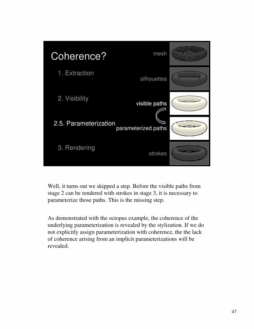
mesh
silhouettes1. Extraction
visible paths2. Visibility
strokes3. Rendering
parameterized paths2.5. Parameterization
visible paths
Coherence?
Well, it turns out we skipped a step. Before the visible paths from
stage 2 can be rendered with strokes in stage 3, it is necessary to
parameterize those paths. This is the missing step.
As demonstrated with the octopus example, the coherence of the
underlying parameterization is revealed by the stylization. If we do
not explicitly assign parameterization with coherence, the the lack
of coherence arising from an implicit parameterizations will be
revealed.
48
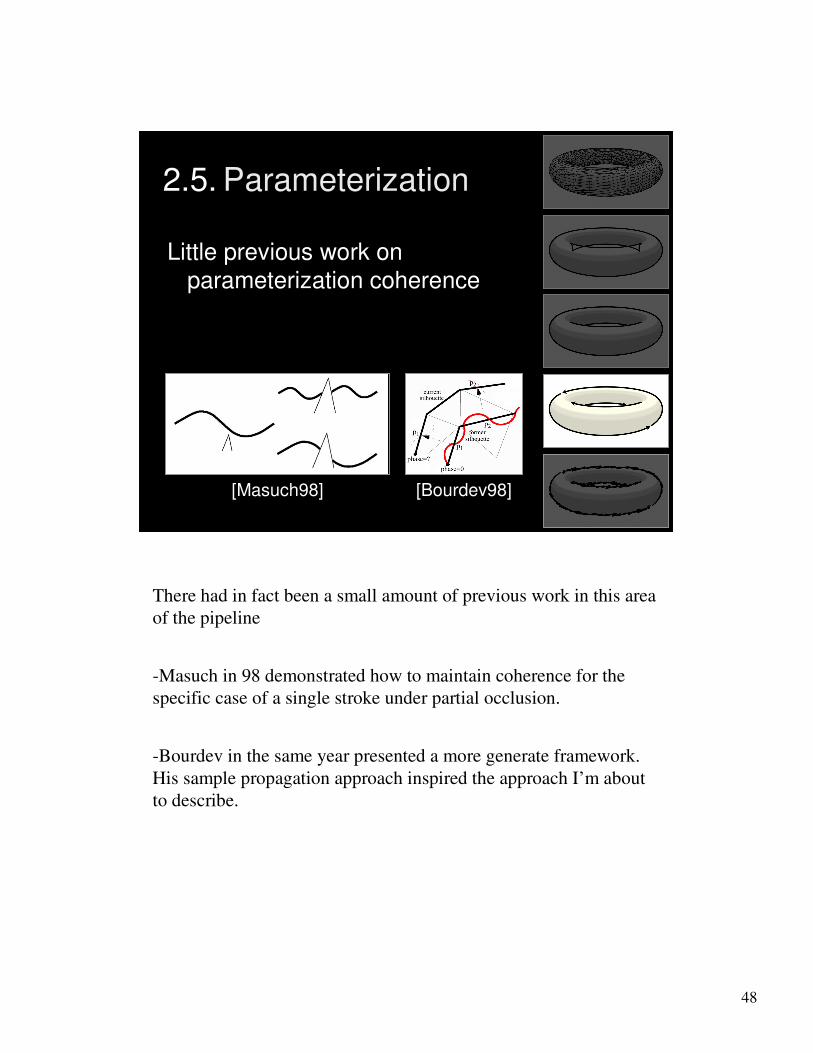
2.5. Parameterization
[Masuch98] [Bourdev98]
Little previous work on
parameterization coherence
There had in fact been a small amount of previous work in this area
of the pipeline
-Masuch in 98 demonstrated how to maintain coherence for the
specific case of a single stroke under partial occlusion.
-Bourdev in the same year presented a more generate framework.
His sample propagation approach inspired the approach I’m about
to describe.

49
Coherent Stylized Silhouettes
frame i frame i+1???
Applications: both offline and interactive animation
Let me concisely state the problem we’ll address here.
Given some stylization of the silhouettes of an animated scene at
time i, how can we achieve a coherent stylization in the next frame,
i+1?
Note that our motivation for considering consecutive frames --
rather than the entire animation as a whole -- is that we want to
achieve coherence in interactive in addition to offline settings.

50
Each sample contains:
• Parameterized path ID
• Parameterization value
• Location on mesh triangle
Propagation: Samples
stroke paths parameterized paths samples
Recall that the stylized strokes are generated on top of a set of
continuously parameterized paths.
To sample this parameterization state for some given frame, we
record a set of discrete samples along each parameterized path.
Within each sample we store the unique ‘id’ of the path it came
from (as denoted by the color coding in the figures), as well as the
value of the parameterization at it’s position along on the path and
its location on a triangle of the mesh (so the sample can be located
in the next frame, even if the mesh deforms).
51
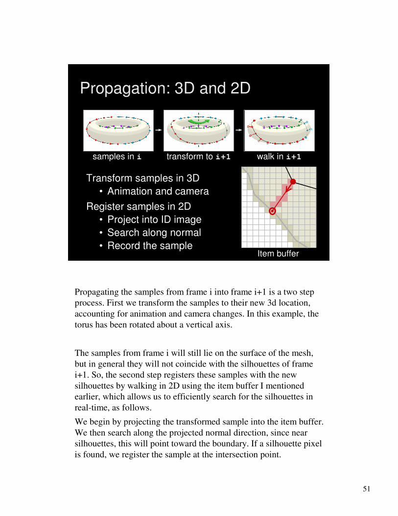
• Record the sample
Propagation: 3D and 2D
Transform samples in 3D
• Animation and camera
Register samples in 2D
• Project into ID image
• Search along normal
samples in i transform to i+1 walk in i+1
Item buffer
Propagating the samples from frame i into frame i+1 is a two step
process. First we transform the samples to their new 3d location,
accounting for animation and camera changes. In this example, the
torus has been rotated about a vertical axis.
The samples from frame i will still lie on the surface of the mesh,
but in general they will not coincide with the silhouettes of frame
i+1. So, the second step registers these samples with the new
silhouettes by walking in 2D using the item buffer I mentioned
earlier, which allows us to efficiently search for the silhouettes in
real-time, as follows.
We begin by projecting the transformed sample into the item buffer.
We then search along the projected normal direction, since near
silhouettes, this will point toward the boundary. If a silhouette pixel
is found, we register the sample at the intersection point.
52
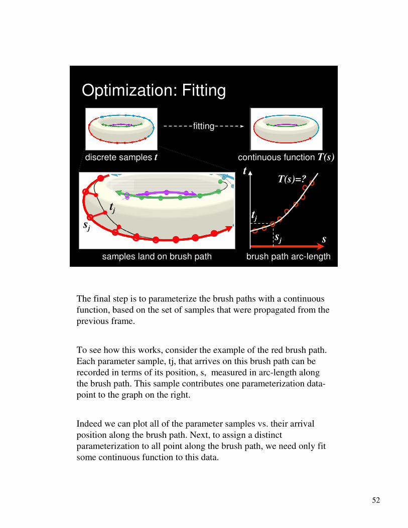
samples land on brush path brush path arc-length
t
s
Optimization: Fitting
discrete samples t continuous function T(s)
fitting
tj
sjtj
sj
T(s)=?
The final step is to parameterize the brush paths with a continuous
function, based on the set of samples that were propagated from the
previous frame.
To see how this works, consider the example of the red brush path.
Each parameter sample, tj, that arrives on this brush path can be
recorded in terms of its position, s, measured in arc-length along
the brush path. This sample contributes one parameterization data-
point to the graph on the right.
Indeed we can plot all of the parameter samples vs. their arrival
position along the brush path. Next, to assign a distinct
parameterization to all point along the brush path, we need only fit
some continuous function to this data.

53
Optimization: Competing Goals
image-spacefeatures
object-spacefeatures
image-spacecoherence
object-spacecoherence
Fitting requires that we identify an objective function for coherence.
However, one of the results of this work was the observation that there is
no single coherence goal suitable for all situations.
First, consider the dotted lines used to stylize this mechanic part. Dotted
lines are image-space features. We want the dot spacing to remain
constant in image-space. Notice how the dots maintain their spacing even
when the object is foreshortened.
On the other end hand, consider thorny features on this cactus. These are
object-spaced features. We expect them to appear stuck to the object like
geometry. However, if we employ the image-space coherence goal.
Notice that in order to maintain image-space density the thorns slide over
the surface as the cactus foreshortens. So image space coherence is not
suitable for object-space features.
Instead, object-space coherence would have features appear stuck on the
silhouette. Notice how the thorns remain in place under foreshortening,
allowing density to change. Finally, if we apply the object-space
coherence goal to image-space features the density of the dots distorts in
an inappropriate way.
In short, our goal for how to fit those samples depends on the nature of
the stylization, and typically, one would choose to strike some balance
between the two forms of coherence.

54
Outline Coherence Results
(VIDEO)
Let me show some video that reveals these effects in action.

55
1. Stylized lines
2. Visibility of lines in 3D
3. How to specify stylization
4. Temporal coherence for stylized lines
Summary
Summary