Part-turn actuators SGC 04.1 SGC 12.1 SGCR 04.1 SGCR 12
60
Control → Parallel Profibus DP Modbus RTU Part-turn actuators SGC 04.1 – SGC 12.1 SGCR 04.1 – SGCR 12.1 with integral actuator controls Assembly, operation, commissioning Operation instructions
Transcript of Part-turn actuators SGC 04.1 SGC 12.1 SGCR 04.1 SGCR 12
Control
→ Parallel
Profibus DP
Modbus RTU
Part-turn actuators
SGC 04.1 – SGC 12.1
SGCR 04.1 – SGCR 12.1
with integral actuator controls
Assembly, operation, commissioningOperation instructions

Read operation instructions first.● Observe safety instructions.● These operation instructions are part of the product.● Retain operation instructions during product life.● Pass on instructions to any subsequent user or owner of the product.
Purpose of the document:
This document contains information for installation, commissioning, operation and maintenance staff. It is intendedto support device installation and commissioning.
Reference documents:
Reference documents can be downloaded from the Internet (www.auma.com) or ordered directly from AUMA(refer to <Addresses>).
Table of contents Page
51. Safety instructions.................................................................................................................51.1. Basic information on safety51.2. Range of application61.3. Applications in Ex zone 22 (option)61.4. Warnings and notes71.5. References and symbols
82. Identification...........................................................................................................................82.1. Name plate92.2. Short description
113. Transport, storage and packaging........................................................................................113.1. Transport113.2. Storage113.3. Packaging
124. Assembly................................................................................................................................124.1. Mounting position124.2. Ball handle to handwheel: fit124.3. Actuator: mount to valve124.3.1. Actuator for assembly: prepare124.3.2. Output drive for coupling134.3.2.1. Mounting with coupling
155. Electrical connection.............................................................................................................155.1. Basic information165.2. Connection via screw-type connector175.2.1. Cable connection185.3. Connection via bayonet connector185.3.1. Cable connection195.4. Connection with AUMA plug/socket connector195.4.1. Terminal compartment: open205.4.2. Cable connection215.4.3. Terminal compartment: close 215.5. Earth connection, external225.6. Accessories for electrical connection
2
SGC 04.1 – SGC 12.1 / SGCR 04.1 – SGCR 12.1Table of contents

225.6.1. Local controls mounted on wall bracket
236. Indications..............................................................................................................................236.1. Mechanical position indicator/running indication236.2. Indication lights
257. Signals.....................................................................................................................................257.1. Output contacts (binary)257.2. Analogue signals
268. Operation................................................................................................................................268.1. Manual operation268.2. Motor operation268.2.1. Local actuator operation278.2.2. Actuator operation from remote
299. Commissioning (basic settings of controls).......................................................................299.1. Cover to controls: open299.2. Setting via hardware (switches) or via software309.3. Type of seating: set319.4. Torque switching: set329.5. Operating time: set349.6. Cover to controls: close
3510. Commissioning (basic settings at actuator)........................................................................3510.1. End stops in part-turn actuator3610.1.1. End stop CLOSED: set3610.1.2. End stop OPEN: set3710.2. End position detection: verify setting3710.3. End position detection: set again via local controls3810.3.1. End position CLOSED: set again3910.3.2. End position OPEN: set again3910.4. Switch compartment: open4010.5. Mechanical position indicator: set4010.6. Switch compartment: close
4111. AUMA CDT software (accessories).......................................................................................
4212. Corrective action....................................................................................................................4212.1. Fault indications and warning indications4312.2. Fuses4312.2.1. Fuses within the actuator controls4312.2.2. Motor protection (thermal monitoring)
4413. Servicing and maintenance...................................................................................................4413.1. Preventive measures for servicing and safe operation4413.2. Maintenance 4413.3. Disposal and recycling
4514. Technical data Part-turn actuator.........................................................................................
4915. Spare parts.............................................................................................................................4915.1. Part-turn actuator SGC 04.1 – SGC 10.1/SGCR 04.1 – SGCR 10.15115.2. Part-turn actuator SGC/SGCR 12.1
5416. Certificates..............................................................................................................................5416.1. Declaration of Incorporation and EC Declaration of Conformity
3
SGC 04.1 – SGC 12.1 / SGCR 04.1 – SGCR 12.1 Table of contents

55Index........................................................................................................................................
57Addresses...............................................................................................................................
4
SGC 04.1 – SGC 12.1 / SGCR 04.1 – SGCR 12.1Table of contents

1. Safety instructions
1.1. Basic information on safety
Standards/directives AUMA products are designed and manufactured in compliance with recognisedstandards and directives. This is certified in a Declaration of Incorporation and anEC Declaration of Conformity.
The end user or the contractor must ensure that all legal requirements, directives,guidelines, national regulations and recommendations with respect to assembly,electrical connection, commissioning and operation are met at the place of installation.
Safety instructions/warn-ings
All personnel working with this device must be familiar with the safety and warninginstructions in this manual and observe the instructions given. Safety instructionsand warning signs on the device must be observed to avoid personal injury or propertydamage.
Qualification of staff Assembly, electrical connection, commissioning, operation, and maintenance mustbe carried out exclusively by suitably qualified personnel having been authorised bythe end user or contractor of the plant only.
Prior to working on this product, the staff must have thoroughly read and understoodthese instructions and, furthermore, know and observe officially recognised rulesregarding occupational health and safety.
Commissioning Prior to commissioning, it is important to check that all settings meet the requirementsof the application. Incorrect settings might present a danger to the application, e.g.cause damage to the valve or the installation. The manufacturer will not be heldliable for any consequential damage. Such risk lies entirely with the user.
Operation Prerequisites for safe and smooth operation:
● Correct transport, proper storage, mounting and installation, as well as carefulcommissioning.
● Only operate the device if it is in perfect condition while observing these instruc-tions.
● Immediately report any faults and damage and allow for corrective measures.● Observe recognised rules for occupational health and safety.● Observe the national regulations.● During operation, the housing warms up and surface temperatures > 60 °C may
occur.To prevent possible burns, we recommend checking the surface temper-ature using an appropriate thermometer and wearing protective gloves, if re-quired, prior to working on the device.
Protective measures The end user or the contractor are responsible for implementing required protectivemeasures on site, such as enclosures, barriers, or personal protective equipmentfor the staff.
Maintenance To ensure safe device operation, the maintenance instructions included in this manualmust be observed.
Any device modification requires prior consent of the manufacturer.
1.2. Range of application
AUMA part-turn actuators are designed for the operation of valves, e.g. butterflyvalves and ball valves.
Other applications require explicit (written) confirmation by the manufacturer.
The following applications are not permitted, e.g.:
● Industrial trucks according to EN ISO 3691● Lifting appliances according to EN 14502● Passenger lifts according to DIN 15306 and 15309● Service lifts according to EN 81-1/A1
5
SGC 04.1 – SGC 12.1 / SGCR 04.1 – SGCR 12.1 Safety instructions

● Escalators● Buried service● Continuous submersion (observe enclosure protection)● Potentially explosive atmospheres● Radiation exposed areas in nuclear power plantsNo liability can be assumed for inappropriate or unintended use.
Observance of these operation instructions is considered as part of the device'sdesignated use.
Information These operation instructions are only valid for the "clockwise closing" standardversion, i.e. driven shaft turns clockwise to close the valve.
1.3. Applications in Ex zone 22 (option)
Actuators of category Ex II3D basically meet the requirements for applications indust hazardous locations of ZONE 22 in compliance with the ATEX directive 94/9/EC.
Actuators for zone 22 are at least designed in enclosure protection IP65 and complywith the provisions of IEC 60079-0 - Explosive atmospheres - Part 0: Equipment -General requirements.
To comply with all requirements of IEC 60079-0, it is imperative that the followingpoints are observed:
● In compliance with the ATEX directive 94/9/EC, the actuators must be equippedwith an additional identification – II3D IP6X T150 °C.
● The maximum surface temperature of the actuators, based on an ambienttemperature of +70 °C in accordance with IEC 60079-0 section 5.3, is +150 °C.In accordance with section 5.3.2, an increased dust deposit on the equipmentwas not considered for the determination of the maximum surface temperature.
● Fulfilling the requirements of the duty type and the technical data are prerequis-ites for compliance with the maximum surface temperature of devices.
● The connectors may only be connected or disconnected when not live.● The cable glands used also have to meet the requirements of category II3 D
and must at least comply with enclosure protection IP67.● The actuators must be connected by means of an external earth connection to
the equipotential earth bonding or integrated into an earthed piping system.● As a general rule, the requirements of IEC 60079-0 and EN 13463-1 must be
respected in dust hazardous locations. During commissioning, service, andmaintenance, special care as well as qualified and trained personnel are requiredfor the safe operation of actuators.
● Connectors and components remaining live when not connected to a socketare not permissible.
1.4. Warnings and notes
The following warnings draw special attention to safety-relevant procedures in theseoperation instructions, each marked by the appropriate signal word (DANGER,WARNING, CAUTION, NOTICE).
Indicates an imminently hazardous situation with a high level of risk. Failureto observe this warning could result in death or serious injury.
Indicates a potentially hazardous situation with a medium level of risk. Failureto observe this warning could result in death or serious injury.
Indicates a potentially hazardous situation with a low level of risk. Failure toobserve this warning may result in minor or moderate injury. May also be usedwith property damage.
6
SGC 04.1 – SGC 12.1 / SGCR 04.1 – SGCR 12.1Safety instructions

Potentially hazardous situation. Failure to observe this warning may result inproperty damage. Is not used for personal injury.
Arrangement and typographic structure of the warnings
Type of hazard and respective source!
Potential consequence(s) in case of non-observance (option)
→ Measures to avoid the danger→ Further measure(s)
Safety alert symbol warns of a potential personal injury hazard.
The signal word (here: DANGER) indicates the level of hazard.
1.5. References and symbols
The following references and symbols are used in these instructions:
Information The term Information preceding the text indicates important notes and information.
Symbol for CLOSED (valve closed)
Symbol for OPEN (valve open)
Important information before the next step. This symbol indicates what is requiredfor the next step or what has to be prepared or observed.
< > Reference to other sections
Terms in brackets shown above refer to other sections of the document which providefurther information on this topic.These terms are either listed in the index, a headingor in the table of contents and may quickly be found.
7
SGC 04.1 – SGC 12.1 / SGCR 04.1 – SGCR 12.1 Safety instructions

2. Identification
2.1. Name plate
Figure 1: Arrangement of name plates
[1] Actuator name plate[2] Additional plate, e.g. KKS plate (Power Plant Classification System)
Description of actuator name plate
Figure 2: Actuator name plate (example)
[1] Name of manufacturer[2] Address of manufacturer[3] Type designation[4] Order number[5] Actuator serial number[6] Operating time[7] Torque range[8] Current type, mains voltage, mains frequency[9] Electric power (motor)[10] Wiring diagram number[11] Control[12] Can be assigned as an option upon customer request[13] Enclosure protection[14] Type of lubricant[15] Setting range of swing angle[16] Permissible ambient temperature[17] Rated current[18] Type of duty[19] Data Matrix code
8
SGC 04.1 – SGC 12.1 / SGCR 04.1 – SGCR 12.1Identification

Type designation Figure 3: Type designation (example)
1. Type and size of actuator2. Flange size
Type and size These instructions apply to the following devices types and sizes:
Part-turn actuators for open-close duty: SGC 04.1, 05.1, 07.1, 10.1, 12.1
Part-turn actuators for modulating duty: SGCR 04.1, 05.1, 07.1, 10.1, 12.1
Order number The product can be identified using this number and the technical data as well asorder-related data pertaining to the device can be compiled.
Please always state this number for any product inquiries.
On the Internet at http://www.auma.com, we offer a service allowing authorisedusers to download order-related documents such as wiring diagrams and technicaldata (both in German and English), inspection certificates and the operationinstructions when entering the order number.
Actuator serial number Table 1: Description of serial number (with example)
NS1234514051st + 2nd position: Assembly in week
Week 0505
3rd + 4th position:Year of manufacture
Year of manufacture: 201414
All other positionsInternal number for unambiguous product identificationNS12345
Control 24 V DC = Control via parallel interface at 24 V DC control voltage.
0/4 – 20 mA = Control via parallel interface via analogue input 0/4 – 20 mA.
Data Matrix code When registered as authorised user, you may use the AUMA Support App to scanthe Data Matrix code and directly access the order-related product documents withouthaving to enter order number of serial number.
Figure 4: Link to the App store:
2.2. Short description
Part-turn actuator Definition in compliance with EN ISO 5211:
A part-turn actuator is an actuator which transmits a torque to the valve for less thanone full revolution. It need not be capable of withstanding thrust.
AUMA part-turn actuators are driven by an electric motor. For control in motoroperation and for processing the actuator signals, controls are integrated within thehousing. The actuator can be operated easily on site via the local controls. Ahandwheel or crank is provided for manual operation. Manual operation is possiblewithout change-over.
The swing angle is limited by internal end stops. Switching off in end positions maybe either by limit or torque seating.
AUMA CDT The AUMA CDT software (accessories) can be used to establish a connection to acomputer (PC, laptop or PDA). Among others, the software can be used to read inand out data and to save and modify settings.
9
SGC 04.1 – SGC 12.1 / SGCR 04.1 – SGCR 12.1 Identification

The connection between computer and the integral actuator controls is made usinga service cable.
10
SGC 04.1 – SGC 12.1 / SGCR 04.1 – SGCR 12.1Identification

3. Transport, storage and packaging
3.1. Transport
For transport to place of installation, use sturdy packaging.
Hovering load!
Risk of death or serious injury.
→ Do NOT stand below hovering load.→ Attach ropes or hooks for the purpose of lifting by hoist only to housing and NOT
to handwheel.→ Actuators mounted on valves: Attach ropes or hooks for the purpose of lifting
by hoist to valve and NOT to actuator.
3.2. Storage
Danger of corrosion due to inappropriate storage!
→ Store in a well-ventilated, dry room.→ Protect against floor dampness by storage on a shelf or on a wooden pallet.→ Cover to protect against dust and dirt.→ Apply suitable corrosion protection agent to uncoated surfaces.
Long-term storage If the device must be stored for a long period (more than 6 months) the followingpoints must be observed in addition:
1. Prior to storage:Protect uncoated surfaces, in particular the output drive parts and mountingsurface, with long-term corrosion protection agent.
2. At an interval of approx. 6 months:Check for corrosion. If first signs of corrosion show, apply new corrosion protec-tion.
Plastic protective caps supplied when leaving the factory are for transport protectiononly.They have to be replaced for long-term storage. (Heed protection type indicatedon name plate.)
3.3. Packaging
Our products are protected by special packaging for transport when leaving thefactory.The packaging consists of environmentally friendly materials which can easilybe separated and recycled. We use the following packaging materials: wood,cardboard, paper, and PE foil. For the disposal of the packaging material, werecommend recycling and collection centres.
11
SGC 04.1 – SGC 12.1 / SGCR 04.1 – SGCR 12.1 Transport, storage and packaging

4. Assembly
4.1. Mounting position
AUMA actuators can be operated without restriction in any mounting position.
4.2. Ball handle to handwheel: fit
To avoid damage during transport, the ball handle is fitted at the rear of thehandwheel.
Prior to commissioning, mount the ball handle into correct position:
1. Remove cap nut [1] and pull out ball handle [2].2. Insert ball handle [2] in correct position and fasten with cap nut [1].
4.3. Actuator: mount to valve
4.3.1. Actuator for assembly: prepare
Prior to mounting, both valve and actuator must be in the same end position!
● For butterfly valves, the recommended mounting position is end positionCLOSED.
● For ball valves, the recommended mounting position is end position OPEN.In compliance with the order, the actuator is supplied either in position CLOSED orposition OPEN. The mechanical position indicator supplies information on the setposition.
If the actuator position was not modified and agrees with the valve position, theactuator can be mounted in the supplied position.
In case the actuator is in an incorrect position:
1. Operate the actuator into the same position as the valve via push buttons OPEN,STOP, CLOSE while in motor operation. For motor operation, please refer to<Actuator operation at the local controls> chapter.
2. Should the electrical connection not be available at the time of assembly, theactuator can be operated into the required end position using the handwheel.
2.1 Turn the handwheel or the crank handle until reaching the internal endstop of part-turn actuator (same end position OPEN or CLOSED as valve).
2.2 Turn handwheel by approximately two turns (overrun) in the opposite dir-ection.
After this procedure, the actuator can be mounted to the valve.
4.3.2. Output drive for coupling
Application ● For valves with output drive types according to EN ISO 5211● Capable of withstanding thrust
Assembly ● The actuator is mounted to the valve using a coupling placed onto the valveshaft.
● Unbored couplings must be adapted and machined to match the valve shaftprior to mounting (e.g. with bore and keyway, two-flat or square bore)
12
SGC 04.1 – SGC 12.1 / SGCR 04.1 – SGCR 12.1Assembly

Figure 5: Coupling variants
[1] Bore with keyway[2] Square bore[3] Bore with two-flats[4] Valve shaft[5] Output drive flange (size 12.1)
4.3.2.1. Mounting with coupling
Condition: Valve and actuator are in the same end position.
Figure 6: Coupling fitting dimensions
[1] Coupling[2] Valve shaft[3] Grub screw[4] Screw
Table 2: Coupling fitting dimensions
Z max [mm]Y max [mm]X max [mm]Type, size - output mounting flange4062.5SGC/SGCR 04.1-F07
4062.5SGC/SGCR 05.1-F07
5062.5SGC/SGCR 07.1-F07
60103.5SGC/SGCR 10.1-F10
62105SGC/SGCR 12.1-F12
1. Thoroughly degrease mounting faces of output mounting flanges.2. Apply a small quantity of grease to the valve shaft [2].3. Place coupling [1] onto valve shaft [2] and secure against axial slipping by using
a grub screw [3], a circlip or a screw [4]. Thereby, ensure that dimensions X, Yor Z are observed (refer to figure and table <Coupling fitting dimensions>).
4. Apply non-acidic grease at splines of coupling.5. Fit actuator.
Information: Ensure that the spigot (if provided) fits uniformly in the recessand that the flanges are in complete contact.
13
SGC 04.1 – SGC 12.1 / SGCR 04.1 – SGCR 12.1 Assembly

6. If flange bores do not match thread:
6.1 Slightly rotate handwheel until bores line up.
6.2 If required, shift actuator position by one tooth on the coupling.7. Fasten actuator with screws [4].
Information: We recommend applying liquid thread sealing material to thescrews to avoid contact corrosion.
→ Fasten screws [4] crosswise with a torque according to table.
Table 3: Tightening torques for screws
Tightening torque TA [Nm]ScrewsThreads Strength class 8.8
24M8
48M10
14
SGC 04.1 – SGC 12.1 / SGCR 04.1 – SGCR 12.1Assembly
5. Electrical connection
5.1. Basic information
Danger due to incorrect electrical connection
Failure to observe this warning can result in death, serious injury, or property damage.
→ The electrical connection must be carried out exclusively by suitably qualifiedpersonnel.
→ Prior to connection, observe basic information contained in this chapter.→ After connection but prior to applying the voltage, observe the <Commissioning>
and <Test run> chapters.
Wiring diagram/terminalplan
The pertaining wiring diagram/terminal plan (both in German and English) is attachedto the device in a weather-proof bag, together with these operation instructions. Itcan also be requested from AUMA (state order number, refer to name plate) ordownloaded directly from the Internet (http://www.auma.com).
Permissible networks(supply networks)
The actuators are suitable for use in TN and TT networks with directly earthed starpoint. Use in IT networks is permitted while observing the respective <Protection onsite>.
Protection on site For short-circuit protection and for disconnecting the actuator from the mains, fusesand disconnect switches have to be provided by the customer.
The current value for respective sizing is derived from the current consumption ofthe actuator (refer to electrical data sheet).
The actuators are suitable for use in current circuits with a maximum short-circuit1-phase AC current value of 5,000 A root-mean-square (R.M.S). The output data ofthe fuses to be provided on site must not exceed the following values: 15 A/250 Vat a maximum mains current of 5,000 A AC.
Use appropriate insulation monitors when working in power installations, for examplean insulation monitor measuring the pulse code.
We recommend refraining from using residual current devices (RCD). However, ifan RCD is used within the mains, the residual current device must be of type B.
Power supply for thecontrols (electronics)
In case of external supply of the controls (electronics): The external power supplymust have a reinforced insulation against the mains voltage in accordance with IEC61800-5-1 and may only be supplied by a circuit limited to 150 VA in accordancewith IEC 61800-5-1.
Potential of customerconnections
All input signals (control) must be supplied with the same potential.
All output signals (status signals) must be supplied with the same potential.
Safety standards All externally connected devices shall comply with the relevant safety standards.
All connected electric circuits shall comply with the requirements for protectiveseparation.
Cable installation in ac-cordance with EMC
Signal and bus cables are susceptible to interference.
Motor cables are interference sources.
● Lay cables being susceptible to interference or sources of interference at thehighest possible distance from each other.
● The interference immunity of signal and bus cables increases if the cables arelaid close to the earth potential.
● If possible, avoid laying long cables and make sure that they are installed inareas being subject to low interference.
● Avoid long parallel paths with cables being either susceptible to interference orinterference sources.
15
SGC 04.1 – SGC 12.1 / SGCR 04.1 – SGCR 12.1 Electrical connection

● For the connection of remote position transmitters, screened cables must beused.
Type of current, mainsvoltage and mains fre-
quency
Type of current, mains voltage and mains frequency must match the data on themotor name plate.
Figure 7: Name plate (example)
[1] Type of current[2] Mains voltage[3] Mains frequency (for 1-ph AC motors)
Connecting cables ● For device insulation, appropriate (voltage-proof) cables must be used. Specifycables for the highest occurring rated voltage.
● Use connecting cable with appropriate minimum rated temperature.● For connecting cables exposed to UV radiation (outdoor installation), use UV
resistant cables.● The cross-sectional area of every protective earthing conductor which does not
form not part of the supply cable or the cable enclosure, shall, in any case, notbe less than:- With mechanical protection: minimum 2.5 mm²- Without mechanical protection: minimum 4 mm²
5.2. Connection via screw-type connector
Figure 8: Arrangement of connections
[XK1] Power terminals (mains cables)[XK2] Control contacts
Cross sections:
● Power terminals: 1.0 – 1.5 mm² flexible● Control contacts: 0.75 – 1.0 mm² flexible
Hazardous voltage at open connector (capacitor discharge)!
Risk of electric shock.
→ After disconnecting the power supply (removing connector for power terminals),wait at least 5 seconds before touching the pins/sockets.
16
SGC 04.1 – SGC 12.1 / SGCR 04.1 – SGCR 12.1Electrical connection
For version with local controls on wall bracket (option):
Risk of damage to actuator electronics or DCS due to inadvertent exchangingof connectors!
→ Do NOT connect 19-pin signal plug (from DCS) for control contacts [XK2] tosocket for local controls on wall bracket.
5.2.1. Cable connection
Observe prior to connec-tion
● Observe permissible cross sections of connectors used.● Use suitable crimping tools to connect wires:
- For screw-type connectors:e.g. Phoenix 4-arbor crimping pliers
- For bayonet connectors:e.g. Cannon four indent crimping tool
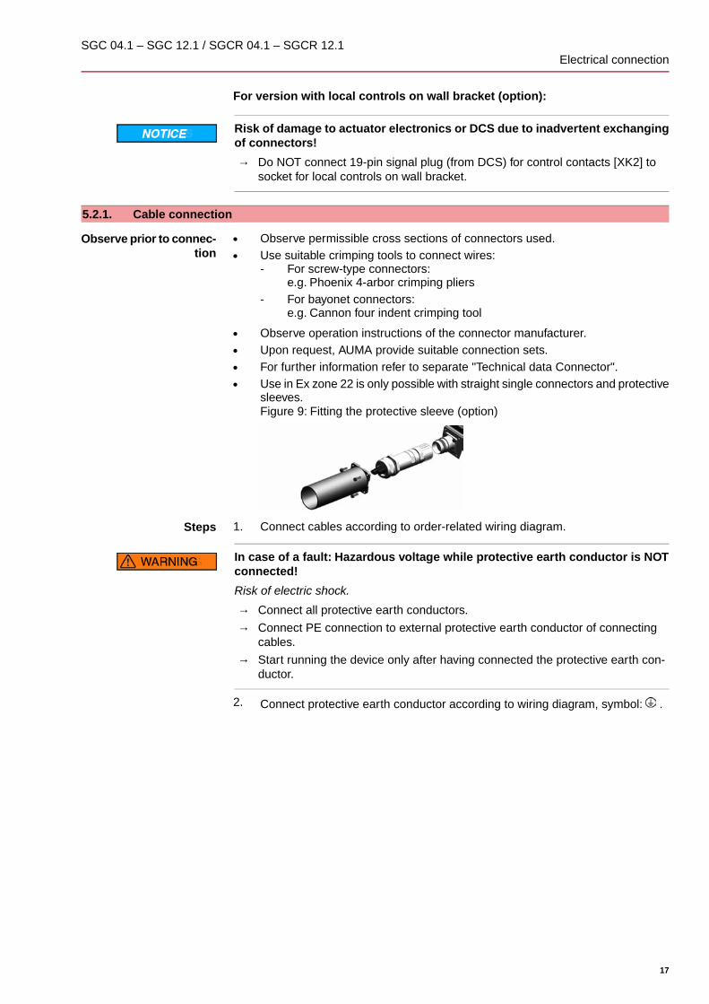
● Observe operation instructions of the connector manufacturer.● Upon request, AUMA provide suitable connection sets.● For further information refer to separate "Technical data Connector".● Use in Ex zone 22 is only possible with straight single connectors and protective
sleeves.Figure 9: Fitting the protective sleeve (option)
Steps 1. Connect cables according to order-related wiring diagram.
In case of a fault: Hazardous voltage while protective earth conductor is NOTconnected!
Risk of electric shock.
→ Connect all protective earth conductors.→ Connect PE connection to external protective earth conductor of connecting
cables.→ Start running the device only after having connected the protective earth con-
ductor.
2. Connect protective earth conductor according to wiring diagram, symbol: .
17
SGC 04.1 – SGC 12.1 / SGCR 04.1 – SGCR 12.1 Electrical connection

5.3. Connection via bayonet connector
Figure 10: Arrangement of connections
[XK1] Power terminals (mains cables)[XK2] Control contacts
Cross sections:
● Power terminals: max. 1.5 mm² flexible● Control contacts: max. 1.5 mm² flexible
Hazardous voltage at open connector (capacitor discharge)!
Risk of electric shock.
→ After disconnecting the power supply (removing connector for power terminals),wait at least 5 seconds before touching the pins/sockets.
5.3.1. Cable connection
Observe prior to connec-tion
● Observe permissible cross sections of connectors used.● Use suitable crimping tools to connect wires:
- For screw-type connectors:e.g. Phoenix 4-arbor crimping pliers
- For bayonet connectors:e.g. Cannon four indent crimping tool
● Observe operation instructions of the connector manufacturer.● Upon request, AUMA provide suitable connection sets.● For further information refer to separate "Technical data Connector".● Use in Ex zone 22 is only possible with straight single connectors and protective
sleeves.Figure 11: Fitting the protective sleeve (option)
Steps 1. Connect cables according to order-related wiring diagram.
18
SGC 04.1 – SGC 12.1 / SGCR 04.1 – SGCR 12.1Electrical connection

In case of a fault: Hazardous voltage while protective earth conductor is NOTconnected!
Risk of electric shock.
→ Connect all protective earth conductors.→ Connect PE connection to external protective earth conductor of connecting
cables.→ Start running the device only after having connected the protective earth con-
ductor.
2. Connect protective earth conductor according to wiring diagram, symbol: .
5.4. Connection with AUMA plug/socket connector
Figure 12: Connection with AUMA plug/socket connector
Cross sections AUMA plug/socket connector:
● Power terminals (U1, V1, W1, U2, V2, W2): max. 6 mm² flexible/10 mm² solid● PE connection : max. 6 mm² flexible/10 mm² solid● Control contacts (1 to 50): max. 2.5 mm²
5.4.1. Terminal compartment: open
Figure 13: Connection AUMA plug/socket connector, version S
[1] Cover[2] Screws for cover[3] O-ring[4] Screws for socket carrier[5] Socket carrier[6] Cable entry[7] Blanking plugs[8] Cable gland (not included in delivery)
19
SGC 04.1 – SGC 12.1 / SGCR 04.1 – SGCR 12.1 Electrical connection

Hazardous voltage!
Risk of electric shock.
→ Disconnect device from the mains before opening.
1. Loosen screws [2] and remove cover [1].2. Loosen screws [4] and remove socket carrier [5] from cover [1].3. Insert cable glands [8] suitable for connecting cables.
➥ The enclosure protection IP… stated on the name plate is only ensured if suit-able cable glands are used.
4. Seal unused cable entries [6] with suitable blanking plugs [7].5. Insert the cables into the cable glands [8].
5.4.2. Cable connection
✔ Observe permissible cross sections.
1. Remove cable sheathing.2. Strip wires.3. For flexible cables: Use end sleeves according to DIN 46228.4. Connect cables according to order-related wiring diagram.
In case of a fault: Hazardous voltage while protective earth conductor is NOTconnected!
Risk of electric shock.
→ Connect all protective earth conductors.→ Connect PE connection to external protective earth conductor of connecting
cables.→ Start running the device only after having connected the protective earth con-
ductor.
5. Tighten PE conductors firmly to PE connection using ring lugs (flexible cables)or loops (rigid cables).
Figure 14: PE connection
[1] Socket carrier[2] Screw[3] Washer[4] Lock washer[5] Protective earth with ring lugs/loops[6] PE connection, symbol:
20
SGC 04.1 – SGC 12.1 / SGCR 04.1 – SGCR 12.1Electrical connection

5.4.3. Terminal compartment: close
Figure 15: Example: Version S
[1] Cover[2] Screws for cover[3] O-ring[4] Screws for socket carrier[5] Socket carrier[6] Cable entry[7] Blanking plugs[8] Cable gland (not included in delivery)
Short-circuit due to pinching of cables!
Risk of electric shock and functional failures.
→ Carefully fit socket carrier to avoid pinching the cables.
1. Insert the socket carrier [5] into the cover [1] and fasten with screws [4].2. Clean sealing faces of cover [1] and housing.3. Check whether O-ring [3] is in good condition, replace if damaged.4. Apply a thin film of non-acidic grease (e.g. petroleum jelly) to the O-ring and
insert it correctly.5. Fit cover [1] and fasten screws [2] evenly crosswise.6. Fasten cable glands [8] applying the specified torque to ensure the required
enclosure protection.
5.5. Earth connection, external
The housing is equipped with an external earth connection (U-bracket) to integratethe device in equipotential earth bonding.
21
SGC 04.1 – SGC 12.1 / SGCR 04.1 – SGCR 12.1 Electrical connection

Figure 16: Earth connection
Earth connection (U-bracket), external
5.6. Accessories for electrical connection
5.6.1. Local controls mounted on wall bracket
— Option —
The wall bracket allows separate mounting of local controls and actuator.
Application If the actuator cannot be accessed safely.
Figure 17: Actuator with local controls on wall bracket
[1] Wall bracket[2] Local controls[3] Phoenix connector with connecting cable
Observe prior to connec-tion
● Permissible length of connecting cables: max. 30 m.● We recommend: AUMA cable set K008.218 (5 m).● A retrofit kit is available for actuators without wall bracket.● Local controls on wall bracket are not approved for use in Ex zone 22.● Establish cable connection via plug/socket connector as illustrated.
Information Do NOT connect 19-pin signal plug (from DCS) to socket for local controls on wallbracket.
22
SGC 04.1 – SGC 12.1 / SGCR 04.1 – SGCR 12.1Electrical connection

6. Indications
6.1. Mechanical position indicator/running indication
Mechanical position indicator:
● Continuously indicates the valve position(For a swing angle of 90°, the indicator disc [2] rotates by approximately 90°.)
● Indicates whether the actuator is running (running indication)● Indicates that the end positions are reached (via indicator mark [3])
Figure 18: Mechanical position indicator
[1] Cover[2] Indicator disc[3] Mark[4] Symbol for position OPEN[5] Symbol for position CLOSED
6.2. Indication lights
Figure 19: Indication lights on local controls
[1] Indication light OPEN/warning/fault (green/yellow/red)[2] Indication light CLOSE/LOCAL/set end position (yellow/blue)
Table 4: Indication light [1] (default setting)
DescriptionSignificationColour/stateActuator is in end position OPEN.OPENilluminated in
green
Stroke between selected end positions (OPEN/CLOSED)is below the preset minimum stroke (factory setting 60 %of maximum rotation). Refer to <Corrective action>chapter.
Warningblinking in yellow
The number of blinking signals indicates the number offault signal. Refer to <Corrective action> chapter.
Faultblinking in red
Table 5: Indication light [2] (default setting)
DescriptionSignificationColour/stateActuator is in end position CLOSED.CLOSEilluminated in yel-
low
23
SGC 04.1 – SGC 12.1 / SGCR 04.1 – SGCR 12.1 Indications

DescriptionSignificationColour/stateOperation mode LOCAL is active. The actuator can beoperated via push buttons.
LOCALblinking in blue(1 Hz)
Setting mode for end position setting is active.Set end positionblinking in blue(5 Hz)
24
SGC 04.1 – SGC 12.1 / SGCR 04.1 – SGCR 12.1Indications

7. Signals
7.1. Output contacts (binary)
The integral controls are equipped with 4 semiconductor output contacts.
Rated power: 24 V DC, 1A
Switches: 1 NO (standard)
Default values:
Designation of output contact in AUMA CDT soft-ware
Designation of output contacts inwiring diagram
Signal DOUT 1 = End position CLOSEDK 1 = End position CLOSED
Signal DOUT 2 = End position OPENK 2 = End position OPEN
Signal DOUT 3 = FaultK 3 = Fault
Signal DOUT 4 = Selector sw. REMOTEK 4 = (Selector switch) REMOTE
7.2. Analogue signals
— Option —
Valve position Signal: E2 = 0/4 – 20 mA (galvanically isolated)
Designation in the wiring diagram:
ANOUT1 (position)
25
SGC 04.1 – SGC 12.1 / SGCR 04.1 – SGCR 12.1 Signals

8. Operation
8.1. Manual operation
For purposes of setting and commissioning, in case of motor failure or power failure,the actuator may be operated manually.
The handwheel does not rotate during motor operation. Change-over from motoroperation to manual operation is not required.
1. Close valve: Turn crank handle/handwheel clockwise.
➥ Drive shaft (valve) turns clockwise in direction CLOSE.
2. Open valve: Turn crank handle/handwheel counterclockwise.
➥ Drive shaft (valve) turns counterclockwise in direction OPEN.
Information Turning the handwheel during motor operation extends or reduces the operatingtime, depending on the direction of rotation.
8.2. Motor operation
✔ Perform all commissioning settings and the test run prior to motor operation.
8.2.1. Local actuator operation
The actuator can be locally operated by means of push buttons.
Figure 20: Local controls
[1] Push button OPEN[2] Push button STOP - operation mode LOCAL/REMOTE[3] Push button CLOSE[4] Indication light for operation mode LOCAL (blue)
26
SGC 04.1 – SGC 12.1 / SGCR 04.1 – SGCR 12.1Operation

Hot surfaces, e.g. possibly caused by high ambient temperatures or strongdirect sunlight!
Danger of burns
→ Check surface temperature and wear protective gloves, if required.
Activate operation mode LOCAL:
→ Hold down push button [2] for approx. 3 seconds until the indication light [4] isblinking in blue.
➥ If the right indication light is blinking in blue, the actuator can be operated viapush buttons [1 – 3]:
- Run actuator in direction OPEN: Press push button OPEN [1].- Stop actuator: Press push button STOP [2].- Run actuator in direction CLOSE: Press push button CLOSE [3].
Information OPEN - CLOSE operation commands can be given either in push-to-run or in self-retaining operation mode. In self-retaining mode, the actuator runs to the definedend position after pressing the button, unless another command has been receivedbeforehand.
Push-to-run operation or self-retaining is set via the controls software. Refer to<AUMA CDT software (accessories)> chapter. It is possible to temporarily (for oneoperation command) activate self-retaining by means of the push buttons:
→ Press and hold down push buttons OPEN [1] or CLOSE [3] for more than 3seconds.
During this procedure, self-retaining is not saved. The setting programmed withinthe software is taken over for the subsequent operation command.
8.2.2. Actuator operation from remote
Operation mode Remote can be activated via local controls.
Figure 21: Local controls
[2] Operation mode LOCAL/REMOTE[4] Indication light for operation mode LOCAL (blue)
Activate operation mode Remote by means of local controls:
→ If indication light [4] is blinking in blue: Hold down push button [2] for approx. 3seconds until the blue indication light goes out.
➥ Now, it is possible to operate the actuator via remote control, via operationcommands (OPEN, STOP, CLOSE) or analogue setpoints (e.g. 0/4 – 20 mA).
Change-over between OPEN - CLOSE control and setpoint control:
For actuators equipped with a positioner, it is possible to select between OPEN -CLOSE control (REMOTE OPEN-CLOSE) and setpoint control (REMOTESETPOINT).
27
SGC 04.1 – SGC 12.1 / SGCR 04.1 – SGCR 12.1 Operation

● MODE input: + 24 V DC = REMOTE OPEN-CLOSEControl is made via digital operation commands OPEN, STOP, CLOSE.
● MODE input: 0 V (or input open-circuit) = REMOTE SETPOINTControl takes place via an analogue signal (e.g. 0/4 – 20 mA).
EMERGENCY operation:
● An EMERGENCY operation is initiated by a signal at the EMERGENCY input.● The actuator moves to a predefined EMERGENCY position (i.e. end position
OPEN or end position CLOSED).● During EMERGENCY operation, the actuator does not react on other operation
commands such as Fieldbus/OPEN/Fieldbus/CLOSE or Fieldbus SETPOINT.
28
SGC 04.1 – SGC 12.1 / SGCR 04.1 – SGCR 12.1Operation

9. Commissioning (basic settings of controls)To prevent valve damage and disturbances during commissioning, the basic settingsof controls must be verified prior to electrical actuator operation (motor operation)and adapted in compliance with the requirements of both valve and application.
Basic settings of controls comprise:
● Setting the type of seating● Setting the torque switches● Setting the operating timeTo perform basic settings, proceed as follows:
1. via switches (directly at the device);For switch setting, open controls cover.
2. via AUMA CDT software (accessories);By connecting a PC, laptop or PDA.Also refer to <AUMA CDT software (accessories)> chapter.
Please also refer to <AUMA CDT software (accessories)> chapter for further settings.
9.1. Cover to controls: open
The cover to the integral controls must be opened to perform the following settings(options).
Hazardous voltage!
Risk of electric shock.
→ Disconnect device from the mains before opening.
→ Loosen 4 screws and remove cover [1] to controls.
9.2. Setting via hardware (switches) or via software
The switch [S5] position determines whether the hardware settings (switches) or thesoftware settings (via AUMA CDT software) are currently active.
Figure 22: Switch [S5] = Hardware/software mode
29
SGC 04.1 – SGC 12.1 / SGCR 04.1 – SGCR 12.1 Commissioning (basic settings of controls)

Table 6: Switch [S5] functions
Hardware mode (factory setting on delivery)Settings of switches [S2] through [S4] and [S6] through [S10] are valid.The values cannot be changed via AUMA CDT software.
OFF
Software mode (sliding switch at white dot)Settings of switches [S2] through [S4] and [S6] through [S10] are NOTrelevant. Settings are defined via software parameters.
ON
9.3. Type of seating: set
Valve damage due to incorrect setting!
→ The type of seating must suit the valve.→ Only change the setting with the consent of the valve manufacturer.
Setting via switches
Condition: Switch [S5] in position OFF (hardware mode).
Figure 23: Switches for type of seating
[S9] End position OPEN[S10] End position CLOSED
Table 7: Function of switches [S9], [S10]
Limit seating, sliding switch at white dotON
Torque seatingOFF
Setting via software parameters (AUMA CDT)
Condition: Switch [S5] is in position ON (software mode).
Setting parameters
Customer settingsType of seatingEnd position CLOSEDEnd position OPEN
Default value: Limit
Setting values:
Limit Limit seating in end positions.
Torque Torque seating in end positions.
30
SGC 04.1 – SGC 12.1 / SGCR 04.1 – SGCR 12.1Commissioning (basic settings of controls)
9.4. Torque switching: set
Valve damage due to excessive tripping torque limit setting!
→ The tripping torque must suit the valve.→ Only change the setting with the consent of the valve manufacturer.
Once the set tripping torque is reached, the controls automatically switch off theactuator (overload protection of the valve).
Setting via switches
Condition: Switch [S5] is in position OFF (hardware mode).
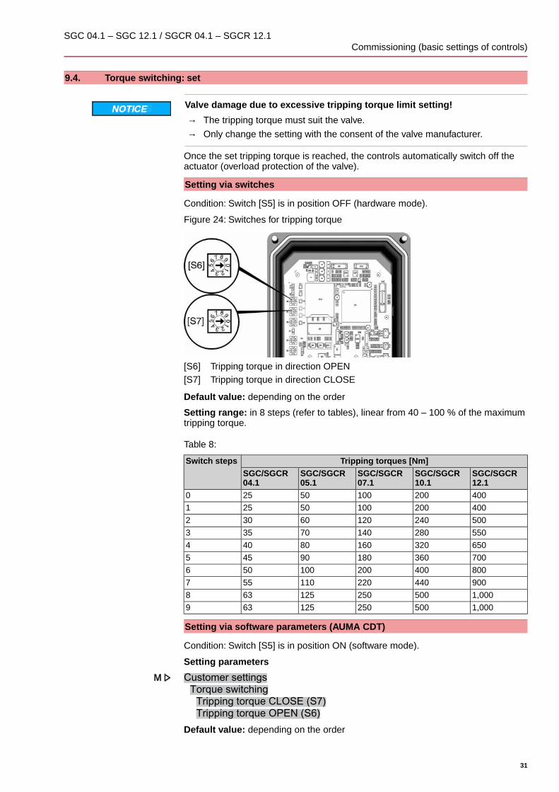
Figure 24: Switches for tripping torque
[S6] Tripping torque in direction OPEN[S7] Tripping torque in direction CLOSE
Default value: depending on the order
Setting range: in 8 steps (refer to tables), linear from 40 – 100 % of the maximumtripping torque.
Table 8:
Tripping torques [Nm]Switch stepsSGC/SGCR12.1
SGC/SGCR10.1
SGC/SGCR07.1
SGC/SGCR05.1
SGC/SGCR04.1
40020010050250
40020010050251
50024012060302
55028014070353
65032016080404
70036018090455
800400200100506
900440220110557
1,000500250125638
1,000500250125639
Setting via software parameters (AUMA CDT)
Condition: Switch [S5] is in position ON (software mode).
Setting parameters
Customer settingsTorque switchingTripping torque CLOSE (S7)Tripping torque OPEN (S6)
Default value: depending on the order
31
SGC 04.1 – SGC 12.1 / SGCR 04.1 – SGCR 12.1 Commissioning (basic settings of controls)

Setting ranges: adjustable between 40 – 100 % of the maximum tripping torque
9.5. Operating time: set
Operating time is defined by the motor speed.
Setting via switches
Switch [S8] is used to change the motor speed and thus the actuator operating time.The preset operating time is valid for both operation modes (Local and Remote).
Condition: Switch [S5] is in position OFF (hardware mode).
Figure 25: Switch for operating time
[S8] Operating time
Default value: depending on the order
Setting range: 9 steps (refer to table)
Table 9:
Operating times for 90° in [s]Switch [S8]Step SGC/SGCR 12.1SGC/SGCR 10.1SGC/SGCR
04.1/05.1/07.1
275901)631)1
206631)451)2
150451)321)3
10332224
7522165
5216116
411187
3085.68
205.649
impermissible switch position0
Motor is operating in stepping mode1)
Setting via software parameters (AUMA CDT)
Motor speed and thus actuator operating time can be modified by means of thesoftware parameters described below. Contrary to operating time setting using switch[S8], setting via software parameter offers the following additional possibilities:
● Different motor speeds for operation modes Local and Remote● Adjustable motor speed setting (operating times)● Motor speed setting (target speed) for operation mode Remote by an external
signal (0/4 – 20 mA) via analogue input AIN 1
Setting parameters
Condition: Switch [S5] is in position ON (software mode).
Device configuration
32
SGC 04.1 – SGC 12.1 / SGCR 04.1 – SGCR 12.1Commissioning (basic settings of controls)

Motor speedSpeed LOCALSpeed REMOTESpeed I/O interface
Description of parameters:
Speed LOCAL Output speed for operation via local controls (operation mode Local); Setting range:linear between 0 – 100 % of max. motor speed; Default value = 50.0 %
Speed REMOTE Output speed in operation mode Remote for setting the Speed I/O interface = Internalparameter; Setting range: linear between 0 – 100 % (0 % = min. motor speed, 100% = max. motor speed); Default value = 50.0 %
Speed I/O interface = ExternalIn operation mode Remote, the output speed is defined via analogue input AIN (0/4– 20 mA).
= InternalIn operation mode Remote, the output speed is not defined via analogue input AIN1 but via the Speed REMOTE software parameter.
Table 10: Example values of type range settings SGC/SGCR 04.1/05.1/07.1
Operating timeOutput drive
[s]
SpeedMotor[rpm]
Output speed via AIN1(Speed I/O interface = External)
Output speed via parameter:Speed LOCALSpeed REMOTE 4 – 20 mA0 – 20 mA
521334.00.00.0 %
223145.41.79.0 %
164316.32.814.0 %
116277.74.723.0 %
88639.56.934.0 %
5.61,23212.310.452.0 %
41,72516.015.075.0 %
3.12,25020.020.0100.0 %
Table 11: Example values of type range settings SGC/SGCR 10.1
Operating timeOutput drive
[s]
SpeedMotor[rpm]
Output speed via AIN1(Speed I/O interface = External)
Output speed via parameter:Speed LOCALSpeed REMOTE 4 – 20 mA0 – 20 mA
811334.00.00.0 %
323385.51.910.0 %
224916.73.417.0 %
166758.15.126.0 %
1192810.48.040.0 %
81,35013.211.557.0 %
5.61,92917.617.085.0 %
4.82,25020.020.0100.0 %
Table 12: Example values of type range settings SGC/SGCR 12.1
Operating timeOutput drive
[s]
SpeedMotor[rpm]
Output speed via AIN1(Speed I/O interface = External)
Output speed via parameter:Speed LOCALSpeed REMOTE 4 – 20 mA0 – 20 mA
2751334.00.00.0 %
2061864.40.52.0 %
1502554.91.26.0 %
1033715.82.311.0 %
755106.93.618.0 %
527428.65.829.0 %
33
SGC 04.1 – SGC 12.1 / SGCR 04.1 – SGCR 12.1 Commissioning (basic settings of controls)
Operating timeOutput drive
[s]
SpeedMotor[rpm]
Output speed via AIN1(Speed I/O interface = External)
Output speed via parameter:Speed LOCALSpeed REMOTE 4 – 20 mA0 – 20 mA
4192810.07.538.0 %
301,29912.811.055.0 %
201,85617.016.381.0 %
172,25020.020.0100.0 %
9.6. Cover to controls: close
1. Clean sealing faces of housing and cover.2. Apply a thin film of non-acidic grease (e.g. petroleum jelly) to the sealing faces.3. Check whether seal is in good condition, replace seal if damaged.4. Apply a thin film of non-acidic grease (e.g. petroleum jelly) to the seal and insert
it correctly.
5. Place cover [1].6. Fasten screws evenly crosswise.
34
SGC 04.1 – SGC 12.1 / SGCR 04.1 – SGCR 12.1Commissioning (basic settings of controls)

10. Commissioning (basic settings at actuator)
10.1. End stops in part-turn actuator
The internal end stops limit the swing angle. They protect the valve in the event oflimit switching failure.
End stop setting is generally performed by the valve manufacturer prior to installingthe valve into the pipework.
Exposed, rotating parts (discs/balls) at the valve!
Pinching and damage by valve or actuator.
→ End stops may be set by suitably qualified personnel only.→ Never completely remove the setting screws [2] and [4] to avoid oil leakage.→ Observe dimension Tmin.
Information ● The swing angle set in the factory is indicated on the name plate:
● The setting sequence depends on the valve:- Recommendations for butterfly valves: Set end stop CLOSED first.- Recommendations for ball valves: Set end stop OPEN first.
Figure 26: End stop, sizes SGC 04.1 – 10.1
[1] Screw plug for end stop OPEN[2] Setting screw for end stop OPEN[3] Screw plug for end stop CLOSED[4] Setting screw for end stop CLOSED
35
SGC 04.1 – SGC 12.1 / SGCR 04.1 – SGCR 12.1 Commissioning (basic settings at actuator)

Figure 27: End stop, size SGC 12.1
[1] Screw plug for end stop OPEN[2] Setting screw for end stop OPEN[3] Screw plug for end stop CLOSED[4] Setting screw for end stop CLOSED
12.110.107.105.104.1Dimen-sions/sizes
2319161313T (for 90°)[mm]
139999Tmin. [mm]
10.1.1. End stop CLOSED: set
1. Remove screw plug [3].2. Move valve to end position CLOSED with handwheel.3. If the valve end position is not reached:
→ Slightly turn setting screw [4] counterclockwise until valve end positionCLOSED can be safely set.
➥ Turning the setting screw [4] clockwise results in a smaller swing angle.
➥ Turning the setting screw [4] counterclockwise results in a larger swingangle.
4. Turn setting screw [4] clockwise to the stop.
➥ This completes the setting of end stop CLOSED.
5. Check O-ring in screw plug [3] and replace if damaged.6. Fasten and tighten screw plug [3].Having completed this procedure, the end position detection CLOSED can be setimmediately.
10.1.2. End stop OPEN: set
Information In general, the end stop OPEN does not have to be set.
1. Remove screw plug [1].2. Move valve to end position OPEN with handwheel.
36
SGC 04.1 – SGC 12.1 / SGCR 04.1 – SGCR 12.1Commissioning (basic settings at actuator)
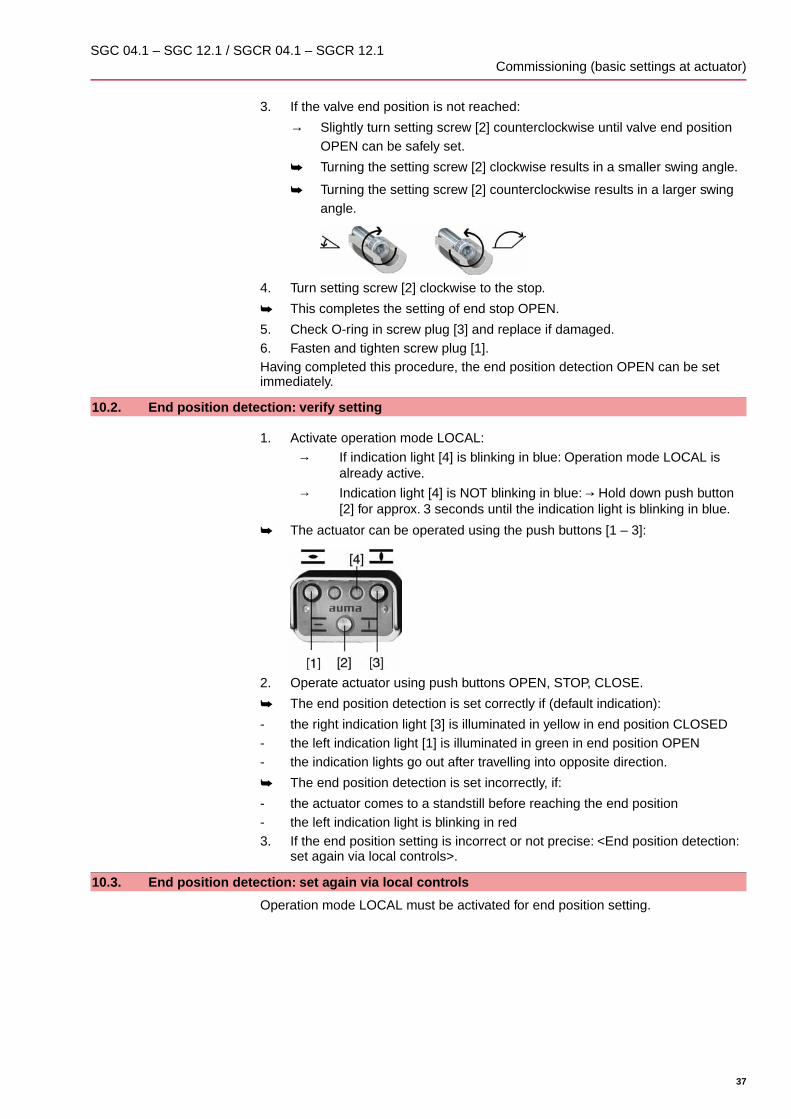
3. If the valve end position is not reached:
→ Slightly turn setting screw [2] counterclockwise until valve end positionOPEN can be safely set.
➥ Turning the setting screw [2] clockwise results in a smaller swing angle.
➥ Turning the setting screw [2] counterclockwise results in a larger swingangle.
4. Turn setting screw [2] clockwise to the stop.
➥ This completes the setting of end stop OPEN.
5. Check O-ring in screw plug [3] and replace if damaged.6. Fasten and tighten screw plug [1].Having completed this procedure, the end position detection OPEN can be setimmediately.
10.2. End position detection: verify setting
1. Activate operation mode LOCAL:→ If indication light [4] is blinking in blue: Operation mode LOCAL is
already active.→ Indication light [4] is NOT blinking in blue: → Hold down push button
[2] for approx. 3 seconds until the indication light is blinking in blue.
➥ The actuator can be operated using the push buttons [1 – 3]:
2. Operate actuator using push buttons OPEN, STOP, CLOSE.
➥ The end position detection is set correctly if (default indication):
- the right indication light [3] is illuminated in yellow in end position CLOSED- the left indication light [1] is illuminated in green in end position OPEN- the indication lights go out after travelling into opposite direction.
➥ The end position detection is set incorrectly, if:
- the actuator comes to a standstill before reaching the end position- the left indication light is blinking in red3. If the end position setting is incorrect or not precise: <End position detection:
set again via local controls>.
10.3. End position detection: set again via local controls
Operation mode LOCAL must be activated for end position setting.
37
SGC 04.1 – SGC 12.1 / SGCR 04.1 – SGCR 12.1 Commissioning (basic settings at actuator)

Activate operation mode LOCAL:
→ Hold down push button [2] for approx. 3 seconds until right indication light isblinking in blue.
Information If the local controls are not provided on site, it is possible to connect an externalcontrol module. The setting is then performed in the same way as described below.
10.3.1. End position CLOSED: set again
Activate setting mode "end position setting":
1. Press push button [2] – hold down and press push buttons [1] and [3] at thesame time.
➥ Now, the right indication light is blinking faster (5 Hz).
Set end position CLOSED:
2. Use crank handle/handwheel or push button [3] for running the actuator to endposition CLOSED. (Actuator runs at reduced output speed in setting mode.)
3. Press push button [2] – hold it down and press push button [3]. Hold both pushbuttons down until the right indication light is blinking alternately in yellow andblue (default).
➥ If the right indication light is blinking in yellow/blue, end position CLOSED settingis complete.
38
SGC 04.1 – SGC 12.1 / SGCR 04.1 – SGCR 12.1Commissioning (basic settings at actuator)

10.3.2. End position OPEN: set again
Activate setting mode "end position setting":
1. Press push button [2] – hold down and press push buttons [1] and [3] at thesame time.
➥ Now, the right indication light is blinking faster (5 Hz).
Set end position OPEN:
2. Use crank handle/handwheel or push button [1] for running actuator to endposition OPEN. (Actuator runs at reduced output speed in setting mode.)
3. Press push button [2] – hold it down and press push button [1]. Hold both pushbuttons down until the left indication light is blinking in green (default).
➥ Once the left indication light is illuminated in green (default), end position OPENsetting is complete.
4. Once both end positions are set, perform a reference operation, i.e. both endpositions must be approached again – either via push buttons [1]/[3] (in operationmode Local) or from Remote (deactivate operation mode Local).
Deactivate operation mode Local:
5. Hold down push button [2] for approx. 3 seconds until blue indication light goesout.
➥ Now, the actuator can be controlled from Remote:
- via operation commands (OPEN - STOP - CLOSE) in positions OPEN orCLOSED.
- as an option via setpoint indication (e.g. 0/4 – 20 mA) in defined positionsbetween 0 % and 100 % of setting range.
10.4. Switch compartment: open
The switch compartment must be opened to perform the following settings (options).
→ Loosen screws [2] and remove cover [1] from the switch compartment.
Figure 28:
39
SGC 04.1 – SGC 12.1 / SGCR 04.1 – SGCR 12.1 Commissioning (basic settings at actuator)

10.5. Mechanical position indicator: set
1. Move valve to end position CLOSED.2. Turn lower indicator disc until symbol (CLOSED) is in alignment with the
mark on the cover.
3. Move actuator to end position OPEN.4. Hold lower indicator disc in position and turn upper disc with symbol (OPEN)
until it is in alignment with the mark on the cover.
5. Move valve to end position CLOSED again.6. Check settings:
If the symbol (CLOSED) s no longer in alignment with mark on the cover:→ Repeat setting procedure.
10.6. Switch compartment: close
1. Clean sealing faces of housing and cover.2. Apply a thin film of non-acidic grease (e.g. petroleum jelly) to the sealing faces.3. Check whether O-ring [3] is in good condition, replace if damaged.4. Apply a thin film of non-acidic grease (e.g. petroleum jelly) to the O-ring and
insert it correctly.
➥
5. Place cover [1] on switch compartment.6. Fasten screws [2] evenly crosswise.
40
SGC 04.1 – SGC 12.1 / SGCR 04.1 – SGCR 12.1Commissioning (basic settings at actuator)
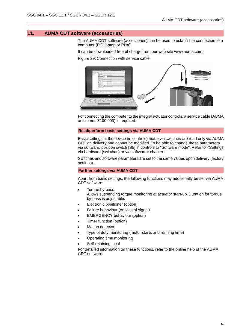
11. AUMA CDT software (accessories)The AUMA CDT software (accessories) can be used to establish a connection to acomputer (PC, laptop or PDA).
It can be downloaded free of charge from our web site www.auma.com.
Figure 29: Connection with service cable
For connecting the computer to the integral actuator controls, a service cable (AUMAarticle no.: Z100.999) is required.
Read/perform basic settings via AUMA CDT
Basic settings at the device (in controls) made via switches are read only via AUMACDT on delivery and cannot be modified. To be able to change these parametersvia software, position switch [S5] in controls to "Software mode". Refer to <Settingsvia hardware (switches) or via software> chapter.
Switches and software parameters are set to the same values upon delivery (factorysettings).
Further settings via AUMA CDT
Apart from basic settings, the following functions may additionally be set via AUMACDT software:
● Torque by-passAllows suspending torque monitoring at actuator start-up. Duration for torqueby-pass is adjustable.
● Electronic positioner (option)● Failure behaviour (on loss of signal)● EMERGENCY behaviour (option)● Timer function (option)● Motion detector● Type of duty monitoring (motor starts and running time)● Operating time monitoring● Self-retaining localFor detailed information on these functions, refer to the online help of the AUMACDT software.
41
SGC 04.1 – SGC 12.1 / SGCR 04.1 – SGCR 12.1 AUMA CDT software (accessories)

12. Corrective action
12.1. Fault indications and warning indications
Faults interrupt or prevent the electrical actuator operation.
Faults and warnings can be signalled via the two output contacts and/or via the localcontrols.
Should local controls be available, the fault and warning signals are indicated by theleft indication light [1].
Figure 30: Fault indications and RESET
[1] Red indication light: Fault, yellow: Warning[2] Push button RESET
In operation mode LOCAL (right indication light is blinking in blue), stored faults(cause does no longer exist), may be reset using the push button RESET [2] (holdit down for more than 1 second).
The tables below show the fault signalling via the indication lights of the local controls.
Table 13: Fault signalling via the red indication light
Signification (default)SignalIndicationTorque fault→ Press push buttons OPEN or CLOSE to re-set the fault (indication light) by operating thedevice in the opposite direction.
Fault indication 11 blink
Thermal fault (motor protection tripped)→ Cool down, wait.
Fault indication 22 blinks
Signal loss of analogue input (4 – 20 mA)Fault indication 33 blinks
Operation mode DISABLED: Operation via thelocal controls is disabled (Enable local controlsfunction).
Fault indication 44 blinks
Fault E2 (actual value of positioner)→ Check wiring (for possible loss of signal) ofE2.→ Read detailed fault indication via AUMACDT software (accessories).
Fault indication 55 blinks
Actuator is outside the permissible position(potentiometer signal).→ Set potentiometer again.
Fault indication 66 blinks
Fault of controls temperatureFault indication 77 blinks
Collective signal: Internal error has occurred.→ Read detailed fault indication via AUMACDT software (accessories) and contactAUMA service.
Fault indication 88 blinks
Collective signal for all other faultsFault indication 99 blinks
In case several faults have occurred, only the fault with the highest priority will besignalled. Fault indication 1 has the highest, fault indication 9 the lowest priority.
42
SGC 04.1 – SGC 12.1 / SGCR 04.1 – SGCR 12.1Corrective action

Table 14: Warning signalling via yellow indication light
Signification (default)SignalIndicationFor reasons of accuracy, we recommend se-lection of the stroke higher than 60 % of themaximum turn range.→ Abort warning: Set again Low limit Uspanparameter via AUMA CDT software within thePosition transmitter potentiometer sub-menu.
WarningBlinking
12.2. Fuses
12.2.1. Fuses within the actuator controls
The primary fuse F1 is located on the power board (device protection fuse). Itbecomes visible when removing the cover to the controls. The fuse cannot bereplaced. Only by replacing the entire power board can the fuse be exchanged.
Hazardous voltage!
Risk of electric shock.
→ Disconnect device from the mains before opening.
Figure 31: Primary fuse on power board
12.2.2. Motor protection (thermal monitoring)
In order to protect against overheating and impermissible high surface temperaturesat the actuator, a PTC thermistor is embedded in the motor winding. Motor protectiontrips as soon as the max. permissible winding temperature has been reached.
The actuator is stopped and controls signals a fault. The left indication light of thelocal controls is blinking in red.
The motor has to cool down before operation can be resumed.
43
SGC 04.1 – SGC 12.1 / SGCR 04.1 – SGCR 12.1 Corrective action

13. Servicing and maintenance
Damage caused by inappropriate maintenance!
→ Servicing and maintenance must be carried out exclusively by suitably qualifiedpersonnel having been authorised by the end user or the contractor of the plant.Therefore, we recommend contacting our service.
→ Only perform servicing and maintenance tasks when the device is switched off.
AUMAService & Support
AUMA offer extensive service such as servicing and maintenance as well as customerproduct training. For the relevant contact addresses, please refer to <Addresses>in this document or to the Internet (www.auma.com).
13.1. Preventive measures for servicing and safe operation
The following measures are required to ensure safe device operation:
6 months after commissioning and then every year
● Check fastening screws between actuator and gearbox/valve for tightness. Ifrequired, fasten screws while applying the tightening torques as indicated inchapter <Assembly>.
● When rarely operated: Perform test run.
For enclosure protection IP68
After continuous immersion:
● Check actuator.● In case of ingress of water, locate leaks and repair, dry device correctly and
check for proper function.
13.2. Maintenance
Maintenance intervals The maintenance intervals depend on load and application conditions having a majorinfluence on the lubricating characteristics of the oil. Maintenance (incl. oil change/sealreplacement) may only be carried out by the AUMA service.
Recommendations for maintenance:● Generally after 4 to 6 years for modulating duty.● Generally after 6 to 8 years if operated frequently (open-close duty).● Generally after 10 to 12 years if operated rarely (open-close duty).No additional lubrication of the gear housing is required during operation.
13.3. Disposal and recycling
Our devices have a long lifetime. However, they have to be replaced at one point intime. The devices have a modular design and may, therefore, easily be separatedand sorted according to materials used, i.e.:
● electronic scrap● various metals● plastics● greases and oilsThe following generally applies:
● Greases and oils are hazardous to water and must not be released into theenvironment.
● Arrange for controlled waste disposal of the disassembled material or for sep-arate recycling according to materials.
● Observe the national regulations for waste disposal.
44
SGC 04.1 – SGC 12.1 / SGCR 04.1 – SGCR 12.1Servicing and maintenance

14. Technical data Part-turn actuator
Weight3)HandwheelValve shaftValve attach-ment
Run torque1)/modulating
torque2)
Torque rangeOperatingtime for 90° in
seconds(adjustable in
9 steps)
Type
approx.[kg]
Turnsfor 90°
∅[mm]
Two-flat
[mm]
Square[mm]
Cyl.[mm]Standard
EN ISO 5211Max.[Nm]
Max.[Nm]50 Hz/60 Hz
SGC/SGCR
7.013.5100171720F05/F073225 – 634 – 6304.17.013.5100171720F05/F076350 – 1254 – 6305.11013.5125222225.4F07125100 – 2504 – 6307.11513.5160273038F10250200 – 5005.6 – 9010.12535125413650F12500400 – 1 00020 – 27512.1
Permissible average torque in open-close duty S2 - 15 min1)Torque in modulating duty S4 - 40 %2)Indicated weight includes part-turn actuator with controls, electrical connection in standard version, unbored coupling and handwheel3)
Features and functions of actuatorShort-time duty S2 - 15 min, classes A and B according to EN 15714-2Open-close duty
SGC:Type of duty
Intermittent duty S4 - 40 % class C in compliance with EN 15714-2 withmaximum number of starts of 1,800 cycles per hour (option)
Modulating dutySGCR:
For nominal voltage and 40 °C ambient temperature and at average running or modulatingtorque load The type of duty must not be exceeded.
Variable speed, brushless motorMotor
F, tropicalizedInsulation class
PTC thermistors (according to DIN 44081)Motor protection
YesSelf-locking
SGC/SGCR 04.1 – 10.1: 82° – 98° adjustable between min. and max.valuesSGC/SGCR 12.1: 75° – 105°
Standard:Swing angle
Available swing angles on requestOptions:
Via position transmitter potentiometer status signals for directions OPEN and CLOSELimit switching
Via electronic current measurement status signals for directions OPEN and CLOSE, adjustablein 8 steps
Torque switching
Continuous indication, adjustable indicator disc with symbols OPEN and CLOSEDMechanical position indicator
Manual drive for setting and emergency operation, handwheel does not rotate during elec-trical operation
Manual operation
Coupling unboredStandard:Coupling● Coupling unbored extended
● Finish machining of coupling (standard or extended)- Bore according to EN ISO 5211 with 1 keyway according to DIN
6885-1- Square bore according to EN ISO 5211- Two-flat according to EN ISO 5211
Options:
Dimensions according to EN ISO 5211Valve attachment
45
SGC 04.1 – SGC 12.1 / SGCR 04.1 – SGCR 12.1 Technical data Part-turn actuator

Features and functions of actuator controlsStandard voltages:
1-phase AC current (voltages/frequencies)230115Volt50/6050/60Hz
Permissible variation of mains voltage: ±10 %Permissible variation of mains frequency: ±5 %For current consumption, current type, mains voltage and frequency, refer to the name plate
Power supply
24 V DC +20 %/–15 %Current consumption: With options up to 200 mAThe external power supply must have a reinforced insulation against mains voltage in accord-ance with IEC 61800-5-1 and may only be supplied by a circuit limited to 150 VA in accordancewith IEC 61800-5-1.
External supply of the electron-ics (option)
Category III according to IEC 60364-4-443Overvoltage category
Power electronics with integral motor controllerPower electronics
The controls are designed for the rated motor power, refer to name plateRated power● 4 digital inputs (via opto-isolator, with one common)
- Control voltage 24 V DC, current consumption: approx. 15 mA per input- Minimum pulse duration for shortest operation pulse: 100 ms.- All digital inputs must be supplied with the same potential.Assignment for open-close actuators:- OPEN, STOP, CLOSE (standard)- OPEN, STOP, CLOSE, EMERGENCY (option)- OPEN, STOP, CLOSE, MODE in combination with positioner (option)- OPEN, EMERGENCY, CLOSE, MODE in combination with positioner (option)Assignment for modulating actuators:- OPEN, STOP, CLOSE, MODE (standard)- OPEN, EMERGENCY, CLOSE, MODE
● Analogue input 0/4 – 20 mA (galvanically isolated)Used as input signal for position setpoint E1 (in combination with positioner) or as inputsignal for motor speed E3.
Control(input signals)
● Output contacts:4 programmable semi-conductor output contacts, per contact max. 24 V DC, 1 A (resistiveload)- 2 NO contacts with one common
Default configuration: End position OPEN, end position CLOSED- 1 potential-free NO contact for collective fault signal
Default configuration: Torque fault, motor protection tripped- 1 potential-free change-over contact
Default configuration: Push button REMOTE
● Analogue output:Galvanically isolated position feedback 0/4 – 20 mA (load max. 500 Ω).
Status signals(output signals)
Auxiliary voltage 24 V DC, max. 40 mA for supply of control inputs, galvanically isolated frominternal voltage supplyNot available for option "external electronics supply".
Voltage output
● Push buttons OPEN, STOP (LOCAL - REMOTE), CLOSE
● 2 multi-colour programmable indication lights:- End position CLOSED (yellow), fault/failure (red), end position
OPEN (green), operation mode LOCAL (blue)
Standard:Local controls
Local controls mounted separately on wall bracketOption:
46
SGC 04.1 – SGC 12.1 / SGCR 04.1 – SGCR 12.1Technical data Part-turn actuator
Features and functions of actuator controls● Switch-off mode adjustable:
- Limit or torque seating for end position OPEN and end position CLOSED
● Torque monitoring across the whole travel
● Torque by-pass
● Programmable EMERGENCY behaviour- Digital input low active- Reaction can be selected: Stop, run to end position CLOSED, run to end position
OPEN
● Positioner (for modulating actuators):- Position setpoint via analogue input E1 = 0/4 – 20 mA- Programmable behaviour on loss of signal- Automatic adaptation of the dead band (adaptive behaviour selectable)- Switch-over between OPEN - CLOSE control (REMOTE OPEN-CLOSE) and setpoint
control (REMOTE SETPOINT) via digital MODE input
Functions
Plug/socket connector with crimp connectionStandard:Electrical connection
AUMA plug/socket connector with screw-type connectionOption:
Refer to name plateWiring diagram
Service conditionsAny positionMounting position
≤ 2 000 m above sea level> 2,000 m above sea level on request
Installation altitude
Refer to name plateStandard: –25 °C to +70 °C
Ambient temperature
Up to 100 % relative humidity across the entire permissible temperature rangeHumidity
Refer to name plateIP68According to AUMA definition, enclosure protection IP68 meets the following requirements:● Depth of water: maximum 8 m head of water
● Duration of continuous immersion in water: Max. 96 hours
● Up to 10 operations during continuous immersion
● Modulating duty is not possible during continuous immersion
Enclosure protection accordingto EN 60529
Pollution degree 4 (when closed) according to IEC 61800-5-1Pollution degree
2 g, from 10 to 200 HzResistant to vibration during start-up or for failures of the plant. However, a fatigue strengthmay not be derived from this.
Vibration resistanceaccording to EN 60068-2-6
Environmental categories D, G, EMC2GL approval (option)
Suitable for use in areas with high salinity, almost permanent con-densation, and high pollution.
KS:Standard:Corrosion protection
Suitable for use in areas with extremely high salinity, permanentcondensation, and high pollution.
KX:Option:
Two-component iron-mica combinationFinish coating
AUMA silver-grey (similar to RAL 7037)Standard:Colour
Available colours on requestOption
20,000 operating cycles OPEN - CLOSE - OPENAn operating cycle is based on an operation from CLOSED to OPEN andback to CLOSED, at a respective rotary movement of 90°.
Open-close duty:Lifetime
5 million modulating stepsModulating duty:
The lifetime depends on the load and the number of starts. A high starting frequency willrarely improve the modulating accuracy. To reach the longest possible maintenance andfault-free operating time, the number of starts per hour chosen should be as low as permissiblefor the process.
47
SGC 04.1 – SGC 12.1 / SGCR 04.1 – SGCR 12.1 Technical data Part-turn actuator

Further informationElectromagnetic Compatibility (EMC): (2004/108/EC)Low Voltage Directive: (2006/95/EC)Machinery Directive: (2006/42/EC)
EU Directives
48
SGC 04.1 – SGC 12.1 / SGCR 04.1 – SGCR 12.1Technical data Part-turn actuator

15. Spare parts
15.1. Part-turn actuator SGC 04.1 – SGC 10.1/SGCR 04.1 – SGCR 10.1
49
SGC 04.1 – SGC 12.1 / SGCR 04.1 – SGCR 12.1 Spare parts

Information: Please state device type and our order number (see name plate) when ordering spare parts. Onlyoriginal AUMA spare parts should be used. Failure to use original spare parts voids the warranty and exemptsAUMA from any liability. Delivered spare parts may slightly vary from the representation in these instructions.
TypeDesignationRef.no.
Sub-as-sembly
Local controls002.0-1
Sub-as-sembly
Cover (for version without local controls)002.0-2
Sub-as-sembly
Cover with socket for connecting separately mounted local controls002.0-3
Sub-as-sembly
Board for local controls 002.0-1002.3-1
Sub-as-sembly
Board in connecting cover 002.0-3002.3-2
Sub-as-sembly
Power supply unit/switchgear006.0
Sub-as-sembly
Logic board009.0
Wire for protective earth058.0
Sub-as-sembly
Cover500.0
Sub-as-sembly
Socket carrier (complete with sockets)501.0
Sub-as-sembly
Pin carrier without pins502.0
Sub-as-sembly
Socket for control503.0
Sub-as-sembly
Socket for motor504.0
Sub-as-sembly
Pin for controls505.0
Sub-as-sembly
Pin for motor506.0
Sub-as-sembly
Cover for electrical connection507.0
Sub-as-sembly
Coupling525.0
Screw plug539.0
Sub-as-sembly
Protective earth connection541.0
Sub-as-sembly
Handwheel542.0
Sub-as-sembly
Ball handle542.1
Sub-as-sembly
Protective cap with cord545.0-1
Sub-as-sembly
Protective cap without cord545.0-2
Sub-as-sembly
Mating plug545.0-3
Wall bracket587.0
Sub-as-sembly
Cover611.0
SetSeal kit, smallS1
50
SGC 04.1 – SGC 12.1 / SGCR 04.1 – SGCR 12.1Spare parts
15.2. Part-turn actuator SGC/SGCR 12.1
51
SGC 04.1 – SGC 12.1 / SGCR 04.1 – SGCR 12.1 Spare parts

Information: Please state device type and our order number (see name plate) when ordering spare parts. Onlyoriginal AUMA spare parts should be used. Failure to use original spare parts voids the warranty and exemptsAUMA from any liability. Delivered spare parts may slightly vary from the representation in these instructions.
TypeDesignationRef.no.
Sub-as-sembly
Local controls002.0-1
Sub-as-sembly
Cover (for version without local controls)002.0-2
Sub-as-sembly
Cover with socket for connecting separately mounted local controls002.0-3
Sub-as-sembly
Local controls board for 022.0-1002.3-1
Sub-as-sembly
Board in connecting cover for 022.0-3002.3-2
Power supply unit/switchgear006.0
Sub-as-sembly
Logic board009.0
Sub-as-sembly
Coupling010.0
Sub-as-sembly
Wire for protective earth058.0
Sub-as-sembly
Cover500.0
Sub-as-sembly
Socket carrier (complete with sockets)501.0
Sub-as-sembly
Pin carrier without pins502.0
Sub-as-sembly
Socket for control503.0
Sub-as-sembly
Socket for motor504.0
Sub-as-sembly
Pin for controls505.0
Sub-as-sembly
Pin for motor506.0
Sub-as-sembly
Cover for electrical connection507.0
Sub-as-sembly
Flange522.0
Sub-as-sembly
Coupling525.0
Screw plug539.0
Sub-as-sembly
Protective earthing541.0
Sub-as-sembly
Handwheel542.0
Sub-as-sembly
Ball handle542.1
Sub-as-sembly
Protective cap with cord545.0-1
Sub-as-sembly
Protective cap without cord545.0-2
Sub-as-sembly
Mating plug545.0-3
Spigot ring548.0
Wall bracket587.0
Sub-as-sembly
Output drive flange596.0
52
SGC 04.1 – SGC 12.1 / SGCR 04.1 – SGCR 12.1Spare parts
TypeDesignationRef.no.
Sub-as-sembly
Angle adapter for mains cables609.1
Sub-as-sembly
Angle adapter for control contacts610.1
Sub-as-sembly
Cover611.0
Screw plug for end stop612.0
SetSeal kit, smallS1
53
SGC 04.1 – SGC 12.1 / SGCR 04.1 – SGCR 12.1 Spare parts

16. Certificates
16.1. Declaration of Incorporation and EC Declaration of Conformity
54
SGC 04.1 – SGC 12.1 / SGCR 04.1 – SGCR 12.1Certificates
Index
AAccessories (electrical con-nection)
22
Actuator: mount to valve 12Ambient temperature 8 , 47Analogue signals 25Applications 5Assembly 12AUMA CDT (accessories) 9 , 41
BBasic setting 35 , 41Basic settings for controls 29
CCDT (accessories) 9 , 41Certificates 54Change-over between OPEN- CLOSE control and setpointcontrol
27
Colour 47Commissioning 5Commissioning (basic set-tings)
35
Commissioning (controls) 29Control 9Corrective action 42Corrosion protection 11 , 47Coupling 45Cross sections 19Current consumption 15
DData Matrix code 9Declaration of Incorporation 54Device type 9Directives 5Disposal 44
EEC Declaration of Conformity 54Electrical connection 15Electric power (motor) 8EMC 15EMERGENCY behaviour 41EMERGENCY operation 28Enclosure protection 8 , 47End position detection setting 37End position detection verific-ation
37
End stops 35
FFailure behaviour 41Fault indications 42Finish coating 47Flange size 9Fuses 43
GGL approval 47Ground connection 21
HHandwheel 12Humidity 47
IIdentification 8Indication lights 23Indications 23Indicator disc 23 , 40Inspection record 9Installation altitude 47Insulation class 45
LLEDs (indication lights) 23Lifetime 47Limit switching 45Local controls 22 , 26Loss of signal 41Lubrication 44
MMains frequency 8 , 16Mains voltage 8 , 16Maintenance 5 , 44 , 44Maintenance intervals 44Manual operation 26 , 45Mechanical position indicator 23 , 40 , 45Modulating duty (REMOTESETPOINT)
27
Monitoring 41Motion detector 41Motor 45Motor operation 26Motor power 8Motor protection 45Mounting position 47
NName plate 8 , 16Network types 15
OOPEN - CLOSE control (Re-mote OPEN - CLOSE)
27
Open-close duty (REMOTEOPEN-CLOSE)
27
Operating time 8Operating time monitoring 41Operating time setting 32Operation 5 , 26Order number 8 , 8 , 9
55
SGC 04.1 – SGC 12.1 / SGCR 04.1 – SGCR 12.1 Index

PPackaging 11Paint 47Pollution degree 47Positioner 41Position indicator 40Power (motor) 8Power supply 15 , 16Programming mode 41Protection on site 15Protective measures 5Push-to-run operation local 27 , 41
QQualification of staff 5
RRange of application 5Rated current 8Recycling 44Remote actuator operation 27Running indication 23
SSafety instructions 5Safety instructions/warnings 5Self-locking 45Self-retaining local 27 , 41Serial number 8 , 9Service 44Servicing 44Setpoint control (RemoteSETPOINT)
27
Setting range of swing angle 8Settings for controls 29Short-circuit protection 15Signals 25Signals (analogue) 25Size 9Software 29 , 41Spare parts 49Standards 5Storage 11Supply networks 15Support 44Support App 9 , 9Swing angle 45Switch [S5] = MODE 41
TTerminal cross sections 16 , 18Terminal plan 15Torque by-pass 41Torque range 8Torque switching 31 , 45Transport 11Type (device type) 9Type designation 8Type of current 8 , 16Type of duty 8 , 45Type of lubricant 8Type of seating 30
VValve attachment 45Vibration resistance 47
WWall bracket 22Wiring diagram 9 , 15Wiring diagram number 8Works number 9
YYear of manufacture 9Year of production 9
56
SGC 04.1 – SGC 12.1 / SGCR 04.1 – SGCR 12.1Index

Europe
AUMA Riester GmbH & Co. KG
Plant MüllheimDE 79373 MüllheimTel +49 7631 809 - [email protected]
Plant Ostfildern-NellingenDE 73747 OstfildernTel +49 711 34803 - [email protected]
Service-Center BayernDE 85386 EchingTel +49 81 65 9017- [email protected]
Service-Center KölnDE 50858 KölnTel +49 2234 2037 - [email protected]
Service-Center MagdeburgDE 39167 NiederndodelebenTel +49 39204 759 - [email protected]
AUMA-Armaturenantriebe Ges.m.b.H.AT 2512 TribuswinkelTel +43 2252 [email protected]
AUMA BENELUX B.V. B. A.BE 8800 RoeselareTel +32 51 24 24 [email protected]
ProStream Group Ltd.BG 1632 SofiaTel +359 2 [email protected]
OOO “Dunkan-Privod”BY 220004 MinskTel +375 29 [email protected]
AUMA (Schweiz) AGCH 8965 BerikonTel +41 566 [email protected]
AUMA Servopohony spol. s.r.o.CZ 250 01 Brandýs n.L.-St.BoleslavTel +420 326 396 [email protected]
GRØNBECH & SØNNER A/SDK 2450 København SVTel +45 33 26 63 [email protected]
IBEROPLAN S.A.ES 28027 MadridTel +34 91 [email protected]
AUMA Finland OyFI 02230 EspooTel +358 9 5840 [email protected]
AUMA France S.A.R.L.FR 95157 Taverny CedexTel +33 1 [email protected]
AUMA ACTUATORS Ltd.GB Clevedon, North Somerset BS21 6THTel +44 1275 [email protected]
D. G. Bellos & Co. O.E.GR 13673 Acharnai, AthensTel +30 210 [email protected]
APIS CENTAR d. o. o.HR 10437 BestovjeTel +385 1 6531 [email protected]
Fabo Kereskedelmi és Szolgáltató Kft.HU 8800 NagykanizsaTel +36 93/[email protected]
Falkinn HFIS 108 ReykjavikTel +00354 540 [email protected]
AUMA ITALIANA S.r.l. a socio unicoIT 20023 Cerro Maggiore (MI)Tel +39 0331 [email protected]
AUMA BENELUX B.V.LU Leiden (NL)Tel +31 71 581 40 [email protected]
NB Engineering ServicesMT ZBR 08 ZabbarTel + 356 2169 [email protected]
AUMA BENELUX B.V.NL 2314 XT LeidenTel +31 71 581 40 [email protected]
SIGUM A. S.NO 1338 SandvikaTel +47 [email protected]
AUMA Polska Sp. z o.o.PL 41-219 SosnowiecTel +48 32 783 52 [email protected]
AUMA-LUSA Representative Office, Lda.PT 2730-033 BarcarenaTel +351 211 307 [email protected]
SAUTECHRO 011783 BucurestiTel +40 372 [email protected]
OOO PRIWODY AUMARU 141402 Khimki, Moscow regionTel +7 495 221 64 [email protected]
OOO PRIWODY AUMARU 125362 MoscowTel +7 495 787 78 [email protected]
ERICHS ARMATUR ABSE 20039 MalmöTel +46 40 [email protected]
ELSO-b, s.r.o.SK 94901 NitraTel +421 905/[email protected]
Auma Endüstri Kontrol Sistemleri LimitedSirketiTR 06810 AnkaraTel +90 312 217 32 [email protected]
AUMA Technology Automations LtdUA 02099 KievTel +38 044 [email protected]
Africa
Solution Technique Contrôle CommandeDZ Bir Mourad Rais, AlgiersTel +213 21 56 42 09/[email protected]
A.T.E.C.EG CairoTel +20 2 23599680 - [email protected]
SAMIREGMA 203000 CasablancaTel +212 5 22 40 09 [email protected]
MANZ INCORPORATED LTD.NG Port HarcourtTel [email protected]
57
AUMA worldwide
AUMA South Africa (Pty) Ltd.ZA 1560 SpringsTel +27 11 [email protected]
America
AUMA Argentina Rep.OfficeAR Buenos AiresTel +54 11 4737 [email protected]
AUMA Automação do Brazil ltda.BR Sao PauloTel +55 11 [email protected]
TROY-ONTOR Inc.CA L4N 8X1 Barrie, OntarioTel +1 705 [email protected]
AUMA Chile Representative OfficeCL 9500414 BuinTel +56 2 821 [email protected]
Ferrostaal de Colombia Ltda.CO Bogotá D.C.Tel +57 1 401 [email protected]
Transcontinental Trading Overseas SA.CU Ciudad HabanaTel +53 7 208 9603 / 208 [email protected]
AUMA Región Andina & CentroaméricaEC QuitoTel +593 2 245 [email protected]
Corsusa International S.A.C.PE Miraflores - LimaTel +511444-1200 / 0044 / [email protected]
Control Technologies LimitedTT Marabella,Trinidad, W.I.Tel + 1 868 658 1744/5011www.ctltech.com
AUMA ACTUATORS INC.US PA 15317 CanonsburgTel +1 724-743-AUMA (2862)[email protected]
SuplibarcaVE Maracaibo, Estado, ZuliaTel +58 261 7 555 [email protected]
Asia
AUMA Actuators UAE Support OfficeAE 287 Abu DhabiTel +971 [email protected]
AUMA Actuators Middle EastBH 152 68 SalmabadTel +97 3 [email protected]
Mikuni (B) Sdn. Bhd.BN KA1189 Kuala BelaitTel + 673 3331269 / [email protected]
AUMA Actuators (China) Co., LtdCN 215499 TaicangTel +86 512 3302 [email protected]
PERFECT CONTROLS Ltd.HK Tsuen Wan, KowloonTel +852 2493 [email protected]
PT. Carakamas Inti AlamID 11460 JakartaTel +62 [email protected]
AUMA INDIA PRIVATE LIMITED.IN 560 058 BangaloreTel +91 80 2839 [email protected]
ITG - Iranians Torque GeneratorIR 13998-34411 [email protected]
Trans-Jordan Electro Mechanical SuppliesJO 11133 AmmanTel +962 - 6 - [email protected]
AUMA JAPAN Co., Ltd.JP 211-0016 Kawasaki-shi, KanagawaTel +81-(0)[email protected]
DW Controls Co., Ltd.KR 153-702 Gasan-dong, GeumChun-Gu,,SeoulTel +82 2 2624 [email protected]
Al-Arfaj Engineering Co WLLKW 22004 SalmiyahTel [email protected]
TOO “Armaturny Center”KZ 060005 AtyrauTel +7 7122 454 [email protected]
Network EngineeringLB 4501 7401 JBEIL, BeirutTel +961 9 [email protected]
AUMA Malaysia OfficeMY 70300 Seremban, Negeri SembilanTel +606 633 [email protected]
Mustafa Sultan Science & Industry Co LLCOM RuwiTel +968 24 [email protected]
FLOWTORK TECHNOLOGIESCORPORATIONPH 1550 Mandaluyong CityTel +63 2 532 [email protected]
M & C Group of CompaniesPK 54000 Cavalry Ground, Lahore CanttTel +92 42 3665 0542, +92 42 3668 [email protected]
Petrogulf W.L.LQA DohaTel +974 [email protected]
AUMA Saudi Arabia Support OfficeSA 31952 Al KhobarTel + 966 5 5359 [email protected]
AUMA ACTUATORS (Singapore) Pte Ltd.SG 569551 SingaporeTel +65 6 [email protected]
NETWORK ENGINEERINGSY Homs+963 31 231 [email protected]
Sunny Valves and Intertrade Corp. Ltd.TH 10120 Yannawa, BangkokTel +66 2 [email protected]
Top Advance Enterprises Ltd.TW Jhonghe City,Taipei Hsien (235)Tel +886 2 2225 [email protected]
AUMA Vietnam Hanoi ROVN Hanoi+84 4 [email protected]
Australia
BARRON GJM Pty. Ltd.AU NSW 1570 ArtarmonTel +61 2 8437 [email protected]
58
AUMA worldwide

59
AUMA worldwide

AUMA Riester GmbH & Co. KG
P.O.Box 1362DE 79373 MuellheimTel +49 7631 809 - 0Fax +49 7631 809 - [email protected]
Y005.017/003/en/1.15
For detailed information on AUMA products, refer to the Internet: www.auma.com


![04.1 Inflation[1]](https://static.fdocuments.us/doc/165x107/577d209d1a28ab4e1e934f11/041-inflation1.jpg)