Part Number: 8600 - Kason Industries...P= _____ (F- 5 1/4”) Trolley in closed door position using...
17
INSTALLATION INSTRUCTIONS © 2019 Kason Industries, Inc. IS-8600EZ-200 Rev 6 03/19 kasonind.com | 1.800.935.2766 | PAGE 1 8600EZ Power Drive Single Doors and Bi-Parting Doors Part Number: 8600* Prefabrication Instructions 1. Begin door prefabrication by following Sections I through V in the 8600EZ SINGLE DOORWARE SYSTEM PREFABRICATION INSTRUCTIONS (IS-8600EZ-14A), except do not install Door Stop (38) at door open end of header as instructed in Section III-D. The open end Door Stop will be installed in a later step. 2. Mounting Motor and Idler. Using Fig. 1 determine where motor and idler are to be mounted and mark their positions. Place motor mounting bracket on header in marked position,center-punch holes, drill for 3/8” bolts. Carriage bolts inserted from the back of header with nuts are recommended. Attach motor onto bracket using supplied bolts (40 in. lbs. MAX), washers and fasten securely. Install sprocket onto shaft. DO NOT HAMMER ON SHAFT! Attach motor bracket(with motor) to header. Place idler mount on opposite end of header from motor and above rail as shown in Fig. 1, center-punch holes, drill for 1/4” bolts and fasten securely. 3. Single Door. Mount door stops (2 required). Using Fig. 1 determine stop locations and mark positions as shown. S = 2 x door opening plus 14”. Install with 3/8” fasteners. (Additional stops may be mounted near bottom of door is desired). 7 1/4 9 1/4 RIGHT HAND OPENING DOOR LEFT HAND OPENING DOOR RAIL IDLER MOUNT MOTOR WITH MOUNT 9 1/4 1/4 7 7 7 1 5/8 1 5/8 4 ½ 4 ½ "S" "S" 6-1/2 DOOR OPENING 6 ½ DOOR OPENING 80 37 Fig. 1 This Booklet Includes: Prefabrication Instructions 1 Job Site Installation 11 Password Protected Drive Programming 16 Parts List 17
Transcript of Part Number: 8600 - Kason Industries...P= _____ (F- 5 1/4”) Trolley in closed door position using...

INSTALLATION INSTRUCTIONS
© 2019 Kason Industries, Inc. IS-8600EZ-200 Rev 6 03/19 kasonind.com | 1.800.935.2766 | PAGE 1
8600EZ Power DriveSingle Doors and Bi-Parting Doors
Part Number: 8600*
Prefabrication Instructions1. Begin door prefabrication by following Sections I through V in the 8600EZ SINGLE DOORWARE SYSTEM PREFABRICATION
INSTRUCTIONS (IS-8600EZ-14A), except do not install Door Stop (38) at door open end of header as instructed in Section III-D. The open end Door Stop will be installed in a later step.
2. Mounting Motor and Idler. Using Fig. 1 determine where motor and idler are to be mounted and mark their positions. Place motor mounting bracket on header in marked position,center-punch holes, drill for 3/8” bolts. Carriage bolts inserted from the back of header with nuts are recommended. Attach motor onto bracket using supplied bolts (40 in. lbs. MAX), washers and fasten securely. Install sprocket onto shaft. DO NOT HAMMER ON SHAFT! Attach motor bracket(with motor) to header. Place idler mount on opposite end of header from motor and above rail as shown in Fig. 1, center-punch holes, drill for 1/4” bolts and fasten securely.
3. Single Door. Mount door stops (2 required). Using Fig. 1 determine stop locations and mark positions as shown. S = 2 x door opening plus 14”. Install with 3/8” fasteners. (Additional stops may be mounted near bottom of door is desired).
7
1/49 1/4
RIGHT HAND OPENING DOOR
LEFT HAND OPENING DOOR
RAIL
IDLERMOUNT
MOTORWITH MOUNT
9 1/41/4
77
7
1 5/8
1 5/8
4 ½
4 ½
"S"
"S"
6-1/2
DOOR OPENING
6 ½
DOOR OPENING
80
37
Fig. 1
This Booklet Includes:Prefabrication Instructions 1Job Site Installation 11Password Protected Drive Programming 16Parts List 17

INSTALLATION INSTRUCTIONS
© 2019 Kason Industries, Inc. IS-8600EZ-200 Rev 6 03/19 kasonind.com | 1.800.935.2766 | PAGE 2
8600EZ Power DriveSingle Doors and Bi-Parting Doors
Part Number: 8600*
Bi-Parting Doors. Mounting door stops. Refer to Fig. 2 and locate trolley and door nearest motor to their intended open position. Trolley must not be closer than 3 1/2” to the end of the rail while in the open position. Locate door stop 3” from the open door edge as shown in Fig. 2 and install with 3/8” fasteners. If trolley does not have 3 1/2” of extra travel on rail with door in the open positions, the door open position must be reset in the closed direction by the necessary distance to give 3 1/2” spacing. Measure distance from motor side door stop to center of opening. Mark same distance from center of opening to opposite end of header and mount remaining door stop.
4. Locate all idler components shown in Fig. 4. Remove hex nut, washer and spring from carriage bolt. Insert carriage bolt through idler mount as shown in Fig. 3 and Fig. 4. Note: Washers and cotter pin securing roller should face outward. Slide spring onto carriage bolt. Add flat washer and start elastic hex locknut onto thread, but do not tighten at this time.
33
3 ½” MIN 3 ½” MINTROLLEYS
RAIL
35
DOOR STOP
35
DOOR STOP
DOORS IN FULLYOPEN POSITIONS
80
MOTOR WITHMOUNT
Fig. 2
Fig. 3 Fig. 4

INSTALLATION INSTRUCTIONS
© 2019 Kason Industries, Inc. IS-8600EZ-200 Rev 6 03/19 kasonind.com | 1.800.935.2766 | PAGE 3
8600EZ Power DriveSingle Doors and Bi-Parting Doors
Part Number: 8600*
5. Single Door. Bolt the upper chain disconnect (Fig. 5) to the trolley using 1/2” bolts as shown in Fig. 7and Fig. 9. Insert bolts with one flat washer through trolley and upper disconnect from bottom. Place flat washer, lock washer and nut on each bolt to complete. Fully tighten the left nut, but only hand-tighten the right side nut at this time.
Bi-Parting Doors. Bolt the upper and lower chain disconnects (Fig. 5 & 6) to the trolley using 1/2” bolts as shown in Fig. 8-A, Fig. 8-B and Fig 9. NOTE: Upper chain disconnect(46) must be mounted to the trolley nearest the EZ power drive unit. Insert bolts with one flat washer through trolley from bottom. Place flat washer, lock washer and nut on each bolt to complete. Fully tighten both nuts on the lower disconnect and the left nut on the upper disconnect. Only hand-tighten the right side nut on the upper disconnect at this time.
Fig. 5 - Upper Disconnect Fig. 6 - Lower Disconnect
See page 4 for reference Drawing with safety switch
Sold in 18600EZ0010 EZ Power Hardware Kit, single door and 18600EZ0011 EZ Power Hardware Kit, Bi-Parting doors
Fig. 7
Fig. 8-A
Fig. 8-B

SAFETY SWITCH INSTALLATION
© 2019 Kason Industries, Inc. IS-8600EZ-200 Rev 6 03/19 kasonind.com | 1.800.935.2766 | PAGE 4
8600EZ Power DriveSingle Doors and Bi-Parting Doors
Part Number: 8600*Attach safety switch to plate using screws and locknuts as shown in Fig. 9. Do not overtighten screws or switch damage can result. Slide plate under flat washer and against upper body until it just touches upper blade, then attach using #8 screw (87). Tighten right side nut to secure upper body and plate to trolley.
Fig. 9
Fig. 10 shows how to remove safety switch electrical cover for wiring. See wiring diagram on page 14. Wire N/C and common contacts of switch in series with safety stop button, using NEC rated control wire. Secure wire to door and wall as needed, and include slack loop for door.
Fig. 10

INSTALLATION INSTRUCTIONS
© 2019 Kason Industries, Inc. IS-8600EZ-200 Rev 6 03/19 kasonind.com | 1.800.935.2766 | PAGE 5
8600EZ Power DriveSingle Doors and Bi-Parting Doors
Part Number: 8600*
8. Installing Inside Release Knob Assembly
a. Place recessed housing in large hole on interior side of door, aligning center hole with a/2” through holes as shown in Fig. 13, (STEP 1). Do not fasten in place at this time.
b. Insert knob/rod into center hole in recessed housing. Push until rod end comes through exterior door face and then place flange over rod ash shown in Fig. 13, (STEP 2).
c. Position parts to rotate freely, then fasten recessed housing and flange to door faces with no. 10 pan head screws as shown in Fig. 13, (STEP 3).
d. Place exterior knob onto rod as shown in Fig. 14, (STEP 4). While holding inside nob, drill 3/16” hole through small hole in knob.
e. Insert cable stud through hole so that square of stud can be held with a wrench, ad tighten lock nut so stud just protrudes as shown in Fig. 14, (STEP 5).
6. Mounting Recessed Inside Release Housing. From the exterior side of the door, drill a 1/2” hole completely through door. Be certain to drill square to the door face as shown in Fig. 11, (STEP No. 1). From the interior side of door, cut a 6” diameter hole located on center of the 1/2” through hole, cutting only to a depth of 1-5/8” as shown in Fig. 11, (STEP No. 2).
NOTE: Inside Release knob should be positioned so that it can be turned with one hand while grasping the door handle with the other. Check interior of door for proper placement.
7. Hollow out the insulation within the cut-out area to the 1-5/8” depth. Hole should accept recessed housing as shown in Fig. 12. Check fit by placing recessed housing in large hole on interior side of door, aligning center hole with 1/2” through hole.
Fig. 11 Fig. 12
Fig. 13 Fig. 14

INSTALLATION INSTRUCTIONS
© 2019 Kason Industries, Inc. IS-8600EZ-200 Rev 6 03/19 kasonind.com | 1.800.935.2766 | PAGE 6
8600EZ Power DriveSingle Doors and Bi-Parting Doors
Part Number: 8600*
9. Mounting Shoes. Locate shoes as shown in Fig. 15, and using shoe as a template, drill 11/64 holes. Stack two shoes together at each location and fasten to rail with No. 10 flat head screws provided.
NOTE: Shoes prevent chain from making incidental contact with rail.
10. Adjusting length of chain for single doors. Measure DIM Q as shown in Fig. 16. Calculate formula below to find chain length for single door systems.
Fig. 15
Fig. 16

INSTALLATION INSTRUCTIONS
© 2019 Kason Industries, Inc. IS-8600EZ-200 Rev 6 03/19 kasonind.com | 1.800.935.2766 | PAGE 7
8600EZ Power DriveSingle Doors and Bi-Parting Doors
Part Number: 8600*
Bi-Parting Doors. Determining chain length for Bi-Parting doors. Locate centerline of rail and make a mark DIM P on either side of center. Locate trolleys at these marks. Measure DIM Q_________; DIM R ______; DIM S ______ and DIM T _____as shown in Fig. 17. Calculate formula below to find chain length.
P= __________ (F- 5 1/4”) Trolley in closed door position using KASON Safety Edge.**
_________ (F- 5 1/2”) Trolley in closed door position using KASON Bulb Gasket. **
FIRST CHAIN LENGTH = R + Q + 2 1/4’ = ___________
SECOND CHAIN LENGTH = T + S + 6 7/8” = _____________
Fig. 17
INSTALLATION INSTRUCTIONS
© 2019 Kason Industries, Inc. IS-8600EZ-200 Rev 6 03/19 kasonind.com | 1.800.935.2766 | PAGE 8
8600EZ Power DriveSingle Doors and Bi-Parting Doors
Part Number: 8600*
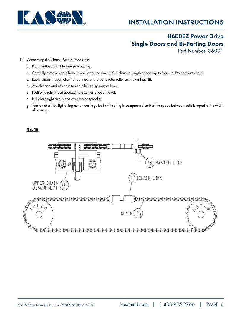
11. Connecting the Chain - Single Door Units
a. Place trolley on rail before proceeding.
b. Carefully remove chain from its package and uncoil. Cut chain to length according to formula. Do not twist chain.
c. Route chain through chain disconnect and around idler roller as shown Fig. 18.
d. Attach each end of chain to chain link using master links.
e. Position chain link at approximate center of door travel.
f. Pull chain tight and place over motor sprocket.
g. Tension chain by tightening nut on carriage bolt until spring is compressed so that the space between coils is equal to the width of a penny.
Fig. 18

INSTALLATION INSTRUCTIONS
© 2019 Kason Industries, Inc. IS-8600EZ-200 Rev 6 03/19 kasonind.com | 1.800.935.2766 | PAGE 9
8600EZ Power DriveSingle Doors and Bi-Parting Doors
Part Number: 8600*
Connecting the Chain - Bi-parting Door Units
a. Place trolleys on rail before proceeding.
b. Carefully remove chain from its package and uncoil. Cut first and second chains to length according to formulas. Do not twist chain.
c. Using master links, attach one chain link to each end of first chain oriented as shown in Fig. 19.
d. Route lower chain link through lower disconnect and attach second chain using master link.
e. Route upper chain link through upper disconnect pulling second chain around idler.
f. Fasten remaining chain end to chain link on upper disconnect using master link.
g. Pull chain tight and place over motor sprocket.
h. Tension chain by tightening nut on carriage bolt until spring is compressed so that the space between coils is equal to the width of a penny.
i. The trolley’s travel limits will be adjusted later in Section III of the instructions during Drive Programming and Setup.
j. When in closed position, all wheels of both trolleys should be on lower position of ramp.
Fig. 19

INSTALLATION INSTRUCTIONS
© 2019 Kason Industries, Inc. IS-8600EZ-200 Rev 6 03/19 kasonind.com | 1.800.935.2766 | PAGE 10
8600EZ Power DriveSingle Doors and Bi-Parting Doors
Part Number: 8600*
12. Single Door. - Install chain disconnect cable as shown in Fig. 20 before proceeding to Electrical installation. Engage upper chain disconnect (Fig. 7) with door approximately centered in travel.
WARNING! Door must be engaged with chain prior to power drive operation. Install all safety stickers shown in Fig. 20 and Fig. 22. Failure to engage chain could result in damage to the power system.
Bi-Parting Doors. - Install chain disconnect cables as shown in Fig. 21 before proceeding to Electrical installation. Engage chain disconnects (Fig. 7) with doors approximately centered in travel.
WARNING! Doors must be engaged with chains prior to power drive operation. Install all safety stickers shown in Fig. 21 and Fig. 22. Failure to engage chain could result in damage to the power system.
Fig. 20
Fig. 21

INSTALLATION INSTRUCTIONS
© 2019 Kason Industries, Inc. IS-8600EZ-200 Rev 6 03/19 kasonind.com | 1.800.935.2766 | PAGE 11
8600EZ Power DriveSingle Doors and Bi-Parting Doors
Part Number: 8600*
Job Site InstallationStep 1. Begin job site installation by following instruction sheet “Installation Instructions - 8600EZ Single Door System” (IS-8600EZ-14B).
! CAUTION!
Only qualified personnel should wire the motor unit and its remote accessories. Adhere to all local electrical codes when installing this unit.
Mount control box as shown below in Fig. 22 using appropriate fasteners and in the desired locations . Control boxes may be mounted up high and out of reach if desired. NOTE: If control box requires mounting further than 9’ from motor, an intermediate junction box is re-quired. It is NOT recommended to replace or alter the supplied wire inside the motor housing.
Mount photo eye at this time, if used. May be mounted on wall or floor as shown in Fig. 22.
STOP!Assure chain is locked in the chain disconnect or connected to the door. See Fig. 7. WARNING! Door must be engaged with chain prior to power drive operation. Install all safety stickers shown in Fig. 21 and 22. Failure to engage chain could result in damage to the power system.
Fig. 22

INSTALLATION INSTRUCTIONS
© 2019 Kason Industries, Inc. IS-8600EZ-200 Rev 6 03/19 kasonind.com | 1.800.935.2766 | PAGE 12
8600EZ Power DriveSingle Doors and Bi-Parting Doors
Part Number: 8600*
WARNING ! FAILURE TO SELECTPROPER VOLTAGE MAY RESULTIN ELECTRICAL DAMAGE !Step 2.Select AC input voltage. Move the black wire to the
applicable AC voltage matching worksite voltage supply.
Unit is factory wired to 115VAC.
Wiring connections. Open control box and locate/identify the connection points for incoming power AC Inputs (L1, L2 & Ground), motor power and low voltage connection for motor communications and user defined inputs. See Fig. 23. All connections with the exception of AC Input connections, are color coded
Fig. 23
Step 3.Wire AC Input. Ground.
Step 4.Wire AC Input. Line 1 (L1) andLine 2 (L2).

INSTALLATION INSTRUCTIONS
© 2019 Kason Industries, Inc. IS-8600EZ-200 Rev 6 03/19 kasonind.com | 1.800.935.2766 | PAGE 13
8600EZ Power DriveSingle Doors and Bi-Parting Doors
Part Number: 8600*
Step 5. Select fuse for desired voltage: Refer to fuse chart Fig. 24. Kason fuses may be ordered at the same time as the 8600EZ Power Drive, as long as the voltage is known.
Fig. 23
ApplicationAC
Supply DIN Rail Fuse
Fuse Rating
TypeSuggested Model # KASON P/NAmps Volts
Primary
115 L1 and L2 10 600 Slow Blow KLKR 10 8600EZ0928
208 L1 and L2 6 600 Slow Blow KLKR 6 8600EZ0929
230 L1 and L2 6 600 Slow Blow KLKR 6 8600EZ0930
460 L1 and L2 3 600 Slow Blow KLKR 3 8600EZ0931
575 L1 and L2 2 600 Slow Blow KLKR 2
Secondary S1 10 600 Slow Blow KLKR 10
Accessories (AC) UT1 1 250 Fast Blow ABC-1-R
Accessories (DC) UT3 1 250 Fast Blow ABC-1-R
Battery Backup BB 10 600 Slow Blow KLKR 10
Note: Model # refers to BUSSMAN for ABC series
Model # refers to LITTLEFUSE for KLKR and KLDR series
Fuse Installation: Fuses will install correctly into fuse blocks only with the raised “button” end outward as fuse is inserted into holder.
FROM GEARMOTOR
Step 6. Wire gear motor power inside panel. Wire color matches color of connector terminals. See Fig. 23 (Step 1) for location of connectors.
Step 7. Wire gear motor control. Wire color matches color of connector terminals. See Fig. 23 (Step 1) for location of connectors.

INSTALLATION INSTRUCTIONS
© 2019 Kason Industries, Inc. IS-8600EZ-200 Rev 6 03/19 kasonind.com | 1.800.935.2766 | PAGE 14
8600EZ Power DriveSingle Doors and Bi-Parting Doors
Part Number: 8600*
Step 8. Connect Accessories. Kason has provided a 3 button station with the controller cover. Refer to Fig. 26 for control hookup of additional accessories that may be required.
See page 4

INSTALLATION INSTRUCTIONS
© 2019 Kason Industries, Inc. IS-8600EZ-200 Rev 6 03/19 kasonind.com | 1.800.935.2766 | PAGE 15
8600EZ Power DriveSingle Doors and Bi-Parting Doors
Part Number: 8600*
The Controller Navigation Buttons are: Escape, Enter, Up, Down
Step 9. Turn on the AC Power
If upon power up, the display reads: 1st Line Company Name 2nd Line Cycle Count
Step 10. Door Size Calibration
A. Press the “Up” or “Down” button until the display reads “AutoCal Now”
i. Press the “Enter” button.
ii. Display should read “ENTER to Calibr”
NOTE: To exit “AutoCal Now” mode, press the “Down” button once for the display to show “Return to Main” then press “Enter” to return to the main menu.
B. Press the “Enter” button. (The door will cycle to open, then close.)
i. The door should move toward the open position at a slow speed.
NOTE: If the door moves toward the close position, jump to Step 11.
• During opening, the display will show “Status, Calibrate Open”.
• At the open position, the door will press against the open stop retainer.
ii. Upon completing B(i), the door will auto-reverse direction
• During closing, the display will show “Status, Calibrate Close”.
• At the close position, the door will press against the close stop retainer (or the two leaves press together with a bi-parting door) and stop.
• The display should read “Door Size Stored”, “Cycle to complt”.
C. Cycle the door as follows to complete calibration
• Open the door using the “Open” button switch connected to Input 1. (See Step 8, Connector D, pins 1 and 2). The door should open faster than during calibration.
• Close the door using the “Close” button switch connected to Input 1. (See Step 8, Connector D, pins 3 and 4). The door should close faster than during calibration.
SYSTEM IS NOW READY TO USE
Step 11. Direction Reverse
A. Power down the system until the screen goes blank, then power back on.
B. Press the “Up” or “Down” button until screen displays “Ent Pswd”.
C. Press the “Enter” button, then the following sequence of buttons to change direction: ENTER, DOWN, DOWN, ENTER, ESC, ESC, ESC, ESC.
D. Press the “Up” or “Down” button until display reads “Dir Flip”.
E. Press the “Enter” button.
F. Press the “Up” button to change value from 0 to 1 or the “Down” button to change value from 1 to 0.
G. Press the “Enter” button to save this value.
i. Power down the system and repeat Step 10.
INSTALLATION INSTRUCTIONS
© 2019 Kason Industries, Inc. IS-8600EZ-200 Rev 6 03/19 kasonind.com | 1.800.935.2766 | PAGE 16
8600EZ Power DriveSingle Doors and Bi-Parting Doors
Part Number: 8600*
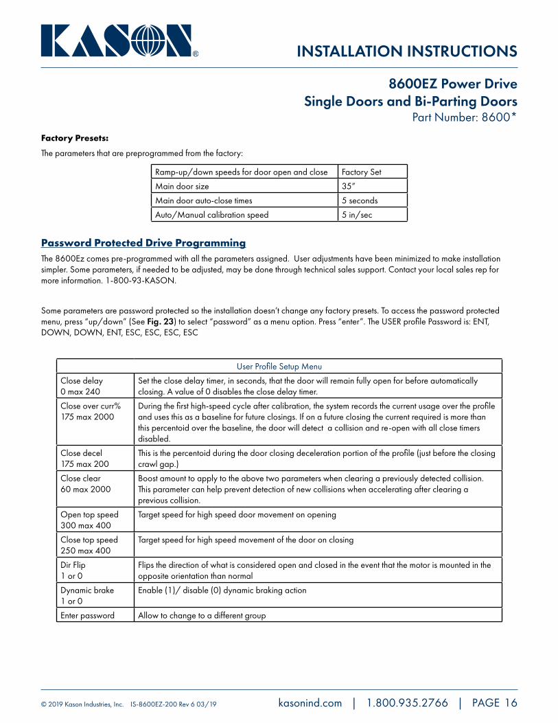
Factory Presets:
The parameters that are preprogrammed from the factory:
Ramp-up/down speeds for door open and close Factory Set
Main door size 35”
Main door auto-close times 5 seconds
Auto/Manual calibration speed 5 in/sec
Password Protected Drive ProgrammingThe 8600Ez comes pre-programmed with all the parameters assigned. User adjustments have been minimized to make installation simpler. Some parameters, if needed to be adjusted, may be done through technical sales support. Contact your local sales rep for more information. 1-800-93-KASON.
Some parameters are password protected so the installation doesn’t change any factory presets. To access the password protected menu, press “up/down” (See Fig. 23) to select “password” as a menu option. Press “enter”. The USER profile Password is: ENT, DOWN, DOWN, ENT, ESC, ESC, ESC, ESC
User Profile Setup Menu
Close delay 0 max 240
Set the close delay timer, in seconds, that the door will remain fully open for before automatically closing. A value of 0 disables the close delay timer.
Close over curr% 175 max 2000
During the first high-speed cycle after calibration, the system records the current usage over the profile and uses this as a baseline for future closings. If on a future closing the current required is more than this percentoid over the baseline, the door will detect a collision and re-open with all close timers disabled.
Close decel 175 max 200
This is the percentoid during the door closing deceleration portion of the profile (just before the closing crawl gap.)
Close clear 60 max 2000
Boost amount to apply to the above two parameters when clearing a previously detected collision. This parameter can help prevent detection of new collisions when accelerating after clearing a previous collision.
Open top speed 300 max 400
Target speed for high speed door movement on opening
Close top speed 250 max 400
Target speed for high speed movement of the door on closing
Dir Flip 1 or 0
Flips the direction of what is considered open and closed in the event that the motor is mounted in the opposite orientation than normal
Dynamic brake 1 or 0
Enable (1)/ disable (0) dynamic braking action
Enter password Allow to change to a different group

INSTALLATION INSTRUCTIONS
© 2019 Kason Industries, Inc. IS-8600EZ-200 Rev 6 03/19 kasonind.com | 1.800.935.2766 | PAGE 17
8600EZ Power DriveSingle Doors and Bi-Parting Doors
Part Number: 8600*Parts List
35. Door Stop37. Idler Mount38. Roller (Idler)39. Holder40(A). Clevis Pin40(B). Cotter Pin41. Deleted Item42. Spring43. Flat Washer44. Carriage Bolt45. Elastic Lock Hex Nut46. Upper Chain Disconnect47. Hex Bolt 1/2”-13 X 1-1/2”48. Flat Washer 1/2”49. Lock Washer 1/2”50. Hex Nut 1/2”-1351. Upper Body52. Upper Blade53. Round Head Screw No. 10x3/8”54. Torsion Spring55. Clevis Pin 3/8”56. Cotter Pin57. Lower Chain Disconnect58. Lower Body59. Lever60. Link61. Chain Guide62. Lower Blade63. Roller Pin64. Push Nut65. Headed Pin 3/16”66. Recessed Housing67. Knob/Rod68. Flange69. Knob70. Cable/Stud71. Lock Nut72. Ring Terminal73. Type “A” Screw No. 10x3/4”74. Flat Head Screw No. 10x5/8”75. Shoe76. Chain No.41x44Ft 6in.77. Chain Link78. Master Link No.41 Chain80. Motor with Mounting Bracket81. Switch Lever82. Groove Pin 1/8x183. Switch Mounting Plate84. Safety Switch85. Screw No.8-32x1/1-1/286. Lock Nut No.887. Screw No.8-32x1/2 Self Tapping88. Chain Label89. Single Button-’Man Door’90. Control Box91. Photo Eye
9850000311 98600004550035K986000009898600004760035K9010750011175090103120111000
986000016001679013850030006298600005540037K9008850011000098600003459000550C11150090138531110062901525001100009008850C1100009860000230986000051000379000319F1103759860000162012790107370112120901031201110009860000346986000022998600005860037986000020600359860000925011798600005400037901021253010009020118012020290533001460093R9048600331985000013190048001830035K9860000493011798500003222008819C110000901702509100009002119F1107509002619F1106259860000240011798600001510010986000093700379860000939CONSULT FACTORY98600002250035K12010812011100098600002270035K98600002202001316C1115002008816C1100002002716F11050018600EZ932011718600000278CONSULT FACTORY18600000510