Part number 12100 - PS Engineering :home
14
9800 Martel Road Lenoir City, TN 37772 Tactical Radio Adapter Document P/N 200-002-0002 Revision 6, October 2018 Part number 12100 Installation and Operation Manual PS Engineering, Inc. 2018 © Copyright Notice Any reproduction or retransmittal of this publication, or any portion thereof, without the expressed written permission of PS En- gineering, Inc. is strictly prohibited. For further information contact the Publications Manager at PS Engineering, Inc., 9800 Mar- tel Road, Lenoir City, TN 37772. Phone (865) 988-9800. In certified aircraft, warranty is not valid unless this product is installed by an Authorized PS Engineering dealer.
Transcript of Part number 12100 - PS Engineering :home
9800 Martel Road
Lenoir City, TN 37772
Tactical Radio Adapter
Document P/N 200-002-0002
Revision 6, October 2018
Part number 12100
Installation and Operation Manual
PS Engineering, Inc. 2018 © Copyright Notice
Any reproduction or retransmittal of this publication, or any portion thereof, without the expressed written permission of PS En-gineering, Inc. is strictly prohibited. For further information contact the Publications Manager at PS Engineering, Inc., 9800 Mar-tel Road, Lenoir City, TN 37772. Phone (865) 988-9800.
In certified aircraft, warranty is not valid unless this product is installed by an
Authorized PS Engineering dealer.
PS Engineering Radio Adapter (12100) Series Interface
Installation Manual
200-002-0002 Page ii Rev. 6, Oct. 2-18
Table of Contents
Section I GENERAL INFORMATION ....................................................................... 1-1
1.1 INTRODUCTION............................................................................................ 1-1
1.2 SCOPE ............................................................................................................. 1-1
1.3 EQUIPMENT DESCRIPTION ........................................................................ 1-1
1.4 APPROVAL BASIS – FAA- None ................................................................. 1-1
1.5 SPECIFICATIONS .......................................................................................... 1-2
1.6 EQUIPMENT SUPPLIED ............................................................................... 1-2
1.7 EQUIPMENT REQUIRED BUT NOT SUPPLIED ........................................ 1-2
1.8 LICENSE REQUIREMENTS ......................................................................... 1-2
Section II - Installation .................................................................................................. 2-1
2.1 GENERAL INFORMATION .......................................................................... 2-1
2.1.1 SCOPE ......................................................................................................... 2-1
2.2 Unpacking and Preliminary Inspection ............................................................ 2-1
2.3 Equipment Installation Procedures .................................................................. 2-1
2.3.1 Cooling Requirements ................................................................................. 2-1
2.3.2 Mounting Requirements ............................................................................... 2-1
2.3.3 Mounting Hole configuration....................................................................... 2-1
2.3.4 Connector Assembly .................................................................................... 2-2
2.3.5 Physical Installation ..................................................................................... 2-2
2.4 Cable Harness Wiring ...................................................................................... 2-2
2.4.1 Noise ............................................................................................................ 2-3
2.4.2 Power ........................................................................................................... 2-3
2.4.3 Interface to aircraft audio system ................................................................. 2-3
2.4.4 Interface to non-aviation transceiver ............................................................ 2-3
2.5 Adjustments ..................................................................................................... 2-4
2.6 Operational Checkout ...................................................................................... 2-7
2.7 Final Inspection. ............................................................................................... 2-7
Section III- Operation.................................................................................................... 3-8
Section IV- Warranty and Service ............................................................................... 4-8
4.1 Warranty ........................................................................................................... 4-8
4.2 Factory Service................................................................................................. 4-8
Appendix A- Installation Information and Connector Layout .................................... A
Appendix B Unit Wiring .................................................................................................. A
Appendix C -Instructions for Continuing Airworthiness ............................................. B

PS Engineering Radio Adapter (12100) Series Interface
Installation Manual
200-002-0002 Page 1-1 Rev. 6, Oct. 2-18
Section I GENERAL INFORMATION
1.1 INTRODUCTION
The Radio Adapter (12100) Radio Adapter Interface is a solution for the interface re-
quirements of general aviation avionics and non-aviation communications radios. Before
installing and/or using this product, please read this manual completely.
1.2 SCOPE
This manual provides detailed installation and operation instructions for the PS Engineer-
ing Radio Adapter Interface unit. This includes the following part number:
Model Description Part Number
Radio Adapter Interface Tactical Radio adapter 12100
1.3 EQUIPMENT DESCRIPTION
The Radio Adapter (12100) is designed to interface general aviation aircraft audio sys-
tems to either a commercial 2-way business transceiver or a public service communica-
tion transceiver.
NOTE:
Because of the variety and inconsistency between different equipment manufacturers,
models and configurations, PS Engineering makes no expressed or implied guarantee that
the Radio Adapter will work satisfactorily in all cases. If the equipment fails to perform,
you may return the unit to PS Engineering for a refund without a restocking charge within
30 days of the invoice date. PS Engineering is not responsible for any engineering or re-
moval costs.
1.4 APPROVAL BASIS – FAA- None
The Radio Adapter (12100) is designed and manufactured to exacting quality standards.
However it is designed as a specialty unit for specific applications outside of the existing
Technical Standard Orders.
It is the installers’ responsibility to ascertain and procure the necessary approvals. PS En-
gineering makes no assertions that the Radio Adapter (12100) is approved for installation
in certified aircraft.
Operation is subject to the following conditions:
1. This device may not cause harmful interference.
2. This device must accept any interference received, including interference that may
cause undesired operation.
PS Engineering Radio Adapter (12100) Series Interface
Installation Manual
200-002-0002 Page 1-2 Rev. 6, Oct. 2-18
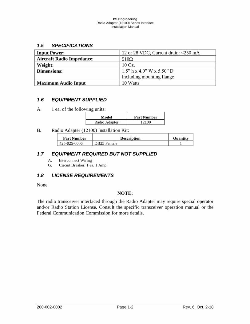
1.5 SPECIFICATIONS
Input Power: 12 or 28 VDC, Current drain: <250 mA
Aircraft Radio Impedance: 510
Weight: 10 Oz.
Dimensions: 1.5” h x 4.0” W x 5.50” D
Including mounting flange
Maximum Audio Input 10 Watts
1.6 EQUIPMENT SUPPLIED
A. 1 ea. of the following units:
Model Part Number
Radio Adapter 12100
B. Radio Adapter (12100) Installation Kit:
Part Number Description Quantity
425-025-0006 DB25 Female 1
1.7 EQUIPMENT REQUIRED BUT NOT SUPPLIED
A. Interconnect Wiring
G. Circuit Breaker: 1 ea. 1 Amp.
1.8 LICENSE REQUIREMENTS
None
NOTE:
The radio transceiver interfaced through the Radio Adapter may require special operator
and/or Radio Station License. Consult the specific transceiver operation manual or the
Federal Communication Commission for more details.
PS Engineering Radio Adapter (12100) Series Interface
Installation Manual
200-002-0002 2-1 Rev. 6, Oct. 2-18
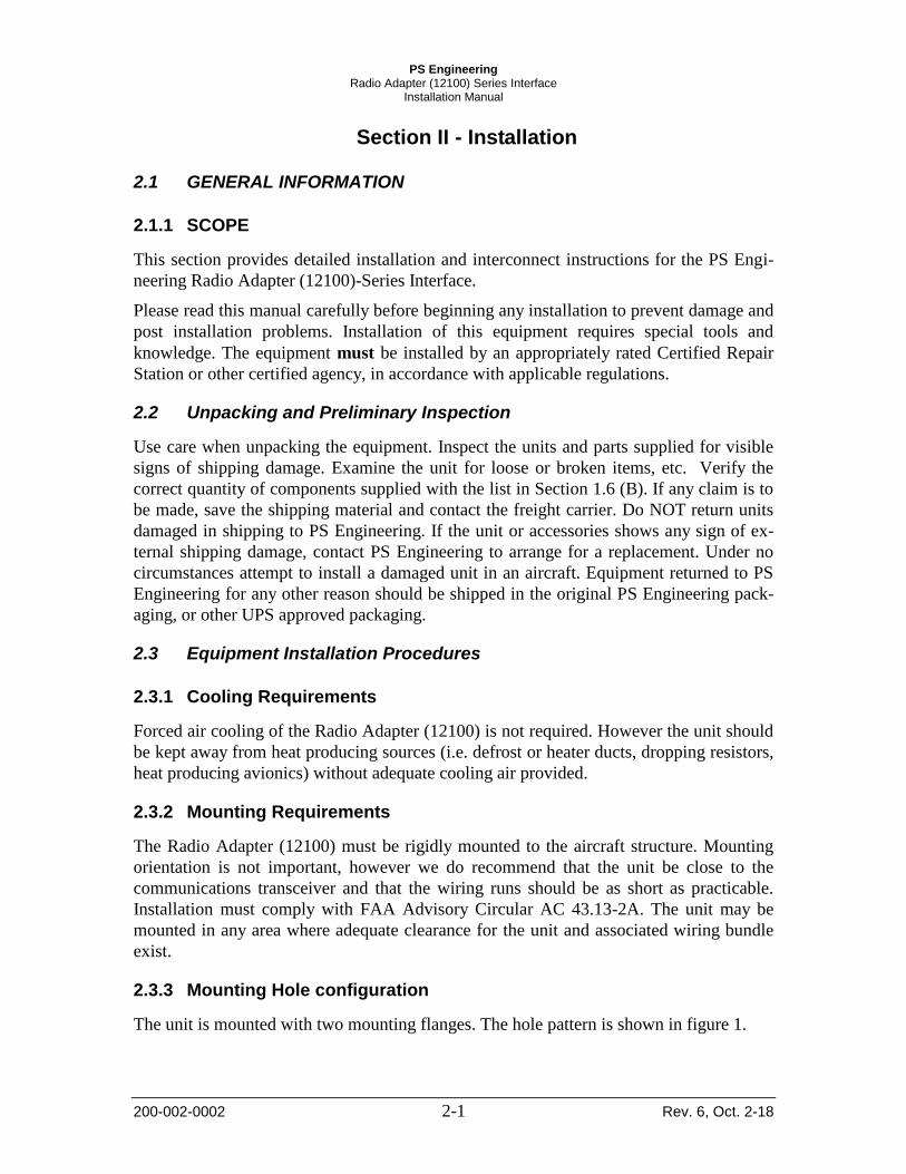
Section II - Installation
2.1 GENERAL INFORMATION
2.1.1 SCOPE
This section provides detailed installation and interconnect instructions for the PS Engi-
neering Radio Adapter (12100)-Series Interface.
Please read this manual carefully before beginning any installation to prevent damage and
post installation problems. Installation of this equipment requires special tools and
knowledge. The equipment must be installed by an appropriately rated Certified Repair
Station or other certified agency, in accordance with applicable regulations.
2.2 Unpacking and Preliminary Inspection
Use care when unpacking the equipment. Inspect the units and parts supplied for visible
signs of shipping damage. Examine the unit for loose or broken items, etc. Verify the
correct quantity of components supplied with the list in Section 1.6 (B). If any claim is to
be made, save the shipping material and contact the freight carrier. Do NOT return units
damaged in shipping to PS Engineering. If the unit or accessories shows any sign of ex-
ternal shipping damage, contact PS Engineering to arrange for a replacement. Under no
circumstances attempt to install a damaged unit in an aircraft. Equipment returned to PS
Engineering for any other reason should be shipped in the original PS Engineering pack-
aging, or other UPS approved packaging.
2.3 Equipment Installation Procedures
2.3.1 Cooling Requirements
Forced air cooling of the Radio Adapter (12100) is not required. However the unit should
be kept away from heat producing sources (i.e. defrost or heater ducts, dropping resistors,
heat producing avionics) without adequate cooling air provided.
2.3.2 Mounting Requirements
The Radio Adapter (12100) must be rigidly mounted to the aircraft structure. Mounting
orientation is not important, however we do recommend that the unit be close to the
communications transceiver and that the wiring runs should be as short as practicable.
Installation must comply with FAA Advisory Circular AC 43.13-2A. The unit may be
mounted in any area where adequate clearance for the unit and associated wiring bundle
exist.
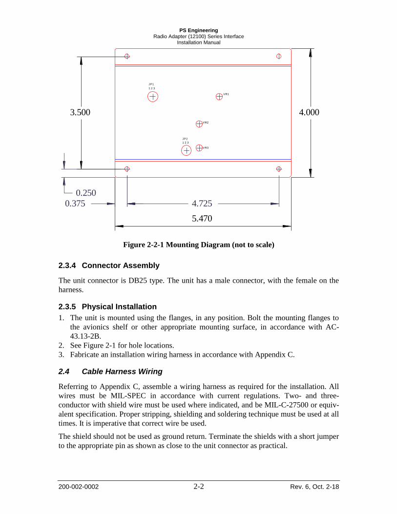
2.3.3 Mounting Hole configuration
The unit is mounted with two mounting flanges. The hole pattern is shown in figure 1.
PS Engineering Radio Adapter (12100) Series Interface
Installation Manual
200-002-0002 2-2 Rev. 6, Oct. 2-18
0.375 4.725
0.250
3.500 4.000
5.470
JP1
1 2 3
JP2
1 2 3
VR3
VR2
VR1
Figure 2-2-1 Mounting Diagram (not to scale)
2.3.4 Connector Assembly
The unit connector is DB25 type. The unit has a male connector, with the female on the
harness.
2.3.5 Physical Installation
1. The unit is mounted using the flanges, in any position. Bolt the mounting flanges to
the avionics shelf or other appropriate mounting surface, in accordance with AC-
43.13-2B.
2. See Figure 2-1 for hole locations.
3. Fabricate an installation wiring harness in accordance with Appendix C.
2.4 Cable Harness Wiring
Referring to Appendix C, assemble a wiring harness as required for the installation. All
wires must be MIL-SPEC in accordance with current regulations. Two- and three-
conductor with shield wire must be used where indicated, and be MIL-C-27500 or equiv-
alent specification. Proper stripping, shielding and soldering technique must be used at all
times. It is imperative that correct wire be used.
The shield should not be used as ground return. Terminate the shields with a short jumper
to the appropriate pin as shown as close to the unit connector as practical.
PS Engineering Radio Adapter (12100) Series Interface
Installation Manual
200-002-0002 2-3 Rev. 6, Oct. 2-18
Refer to FAA Advisory Circular 43.13-2A for more information. Failure to use correct
techniques may result in improper operation, electrical noise or unit failure. Damage
caused by improper installation will void the PS Engineering warranty.
2.4.1 Noise
Due to the variety and the high power of radio equipment often found in today's general
aviation aircraft, there is a potential for both radiated and conducted noise interference.
Ground loop noise occurs when there are two or more ground paths for the same signal
(i.e., airframe and ground return wire). Large cyclic loads such as strobes, inverters, etc.,
can inject noise signals onto the airframe that are detected by the audio system. Follow
the wiring diagram very carefully to help ensure a minimum of ground loop potential. Use
only Mil Spec shielded wires (MIL-C-27500, or better).
Do not run microphone audio and headphone audio in the same, shielded jacket, use sepa-
rate shielded pair. Do not use the shield as a conductor, (audio low, etc) as this will create
potential noise sources.
Radiated signals can be a factor when low level microphone signals are "bundled" with
current carrying power wires. Keep these cables physically separated.
2.4.2 Power
The Radio Adapter (12100) is compatible with both 13.8 and 28 Volt DC systems. A one
(1) Amp circuit breaker is required. Fourteen-volt aircraft supply power through Pin 2,
28VDC aircraft through pin 1. Pins 14 and 15 are aircraft ground. Keep ground wires as
short as possible.
2.4.3 Interface to aircraft audio system
The aircraft-audio output from the Radio Adapter is pin 4 with respect to (WRT) pin 17.
This is a standard 500 audio output, similar to a VHF Communications transceiver.
The microphone audio input is pin 3, WRT 16. This is an aviation-standard dynamic mic
input, similar to a VHF Communications transceiver input. The PTT input on pin 7 is
ground-seeking, like an aviation microphone.
2.4.4 Interface to non-aviation transceiver
The Radio Adapter audio input is transformer-coupled, pin 6, WRT pin 19. This can be
configured for either a 150 or 8 speaker output from the transceiver.
The Microphone output from the Radio Adapter to the transceiver mic input is pin 5
WRT 18. This can be configured for either an 8 or 150 mic, which is amplified or
non-amplified, or 150 , passed directly to the radio. The ground can be either audio low,
or airframe ground referenced.
Many transceivers with hand microphones do not have a mic bias source, necessary for an
aviation headset. Install the jumper at JP1 across pins 1 and 2 to generate a mic bias

PS Engineering Radio Adapter (12100) Series Interface
Installation Manual
200-002-0002 2-4 Rev. 6, Oct. 2-18
source, which will be connected to the aircraft microphone when the transceiver is select-
ed for transmit.
Transceivers with built-in speakers also do not provide sidetone, so VR2 can be adjusted
to cause sidetone to be present during transmission.
The audio input to the radio adapter (pin 6 hi, pin 19 low) is transformer isolated. In some
installations, it may be required to have a common ground to prevent loss of signal or dis-
tortion. In this case, connect pin 19 to pin 15.
2.4.4.1 Push to talk interface
The Radio Adapter is configurable for hi-seeking, low-seeking, or 2-pin contact push-to-
talk (PTT) systems.
Pin 7 is the key-line input from the aircraft audio system. Grounding this line in PTT
causes a 2-pole relay to change states.
For instance, if the tactical radio has a ground seeking PTT line, you ground the common
#1of the relay, Pin 10, and connect the normally open connection, Pin 9 to the unit PTT
input. Keying the aircraft PTT then grounds Pin 9.
Connecting Pin 10 to logic high will pull Pin 9 high in PTT, and so on. If there are two
PTT contacts, one can be connected to common, and the other to NO.
10
22
24
9
12
11 +V
+
Pin 7
Connector Pin
Figure 2 Mic Keying Relay Detail
2.5 Adjustments
The unit can be configured for several different interface combinations. Remove the
unit from its mounting bracket by removing the four screws at corners near the upper
edge.

PS Engineering Radio Adapter (12100) Series Interface
Installation Manual
200-002-0002 2-5 Rev. 6, Oct. 2-18
The following adjustments are available, and marked on the silkscreen:
VR1 Mic Amplitude Control
VR2 Sidetone Adjust
VR3 Audio Output Adjust
The following switch positions are available to configure the unit for specific trans-
ceiver types.
S 1
Switch 1 ON if 8 microphone
Switch 2 ON if microphone
direct connect
Switch 3 ON if amplified mic
Switch 4 ON if Mic output
ground referenced (or
8)
S2
Switch 1 Not Used
Switch 2 ON for 150 mic
Switch 3 ON for 8 mic
Switch 4 ON for 150 mic
S 3
Switch 1 Not Used
Switch 2 ON for 150 speaker
Switch 3 ON for 8 speaker
Switch 4 ON for 150 speaker
The JP 1 header is connected to provide internal mic bias. These are the pins closest
to the unit connector.
The JP2 header connect pins 1 and 2 if higher audio output gain is desired.

PS Engineering Radio Adapter (12100) Series Interface
Installation Manual
200-002-0002 2-6 Rev. 6, Oct. 2-18
Move jumper to 2 pins closest to connector to provide mic bias
Move jumper to pins 1 & 2 to provide more audio gain
Rx Audio Output
Sidetone Level
1 2 3 4
Speaker Select S3
ON if : 1-Blank
2-150Ω SPKR 3- 8Ω SPKR
4-150Ω SPKR
MIC Select S2
ON if : 1-Blank
2-150Ω MIC 3- 8Ω MIC
4-150Ω MIC
1 2 3 4
MIC Select S1
ON if : 1-8Ω MIC
2-DIRECT 3- AMPLIFIED
4-MIC GND REF
1 2 3 4
MIC GAIN
Figure 2-3 Internal Adjustments and settings
12100 Unit Top 12100 Bottom
S1
S2
S3
Speaker Select S3 ON if: 1-Blank 2-150Ω SPKR 3- 8Ω SPKR 4-150Ω SPKR
MIC Select S2 ON if : 1-Blank 2-150Ω MIC 3- 8Ω MIC 4-150Ω MIC
MIC Select S1 ON if : 1-8Ω MIC 2-DIRECT 3- AMPLIFIED 4-MIC GND REF
MIC Gain
Sidetone Level
Rx Audio Level
PS Engineering Radio Adapter (12100) Series Interface
Installation Manual
200-002-0002 2-7 Rev. 6, Oct. 2-18
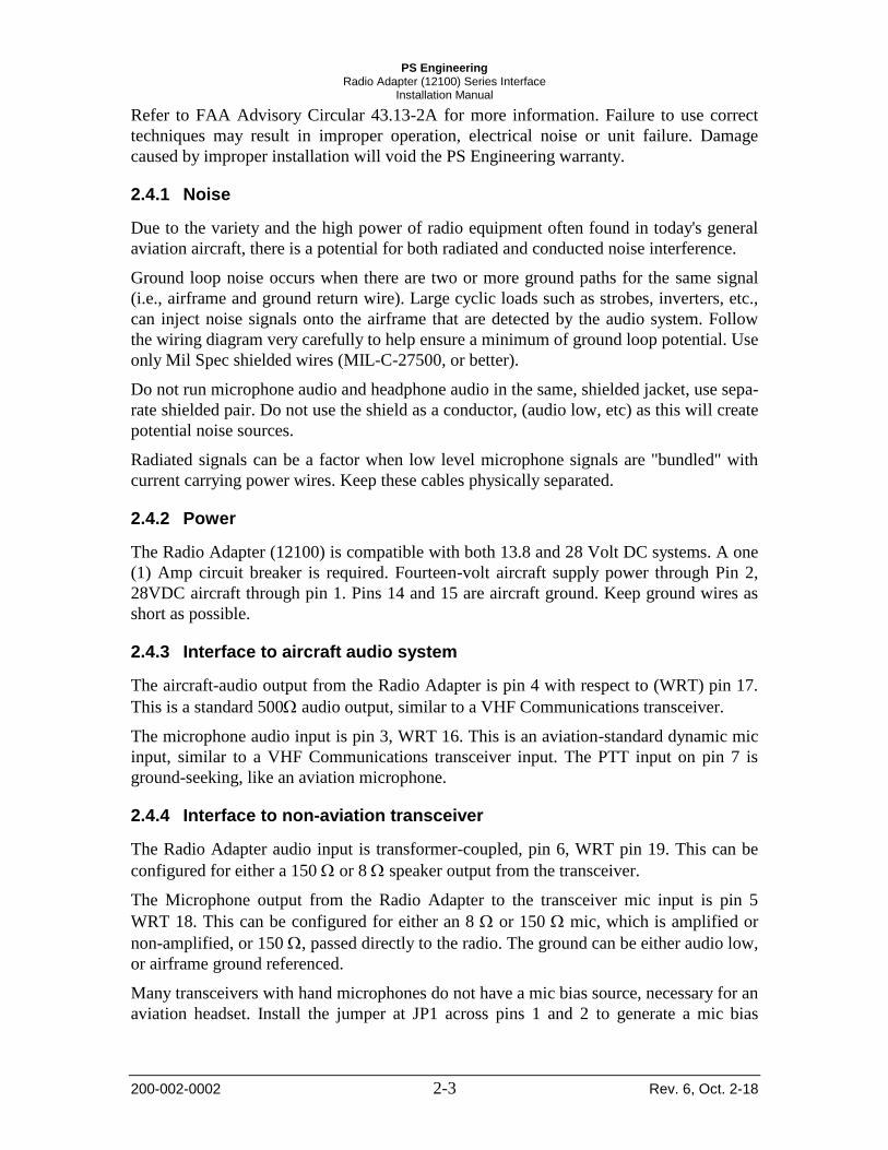
Table of previously used switch combinations:
Midland LMR
70-1340B
Icom ICF121
VHF
YAESU FTM-
400-DR
Kenwood LMR
Switch Condition Condition Condition Condition
S1 - 1 OFF OFF OFF OFF
S1 - 2 ON OFF ON ON
S1 – 3 OFF ON OFF OFF
S1 – 4 OFF ON OFF ON
S2 –1 OFF OFF OFF OFF
S2 – 2 OFF OFF OFF ON
S2 – 3 ON ON OFF OFF
S2 – 4 OFF OFF ON ON
S3 – 1 OFF OFF OFF OFF
S3 – 2 OFF ON OFF ON
S3 – 3 ON OFF ON OFF
S3 – 4 OFF ON OFF ON
JP1 Pins 1 & 2 (Mic bias enabled)
Pins 1 & 2 (Mic bias ena-
bled)
Pins 1 & 2 (Mic bias ena-
bled
JP2 Pins 1 & 2 (Higher gain)
Pins 1 & 2 (Higher gain)
Pins 1 & 2 (Higher gain)
Use the table above as a worksheet. If you will send us your successful combination,
we can add to the list. Fax to: (865) 988-6619.
2.6 Operational Checkout
NOTE: Because the Radio Adapter is designed to interface with commercial or public service/safety transceivers,
your testing may affect other radio services. Verify frequencies and operating procedures before attempting
to transmit on unknown radios.
1. Verify that aircraft power is present only on Pin 1 (28 VDC) or pin 2 (14 VDC).
2. Apply power to the avionics and tactical transceiver.
3. Verify that the receive audio from the tactical radio is present in the aircraft audio sys-
tem when selected.
4. With the transceiver connected to a dummy load, or to an antenna, and operated by
properly rated personnel, press the aircraft PTT, and verify that the transceiver
switches to transmit mode.
5. Verify that there is microphone audio through the system by making a radio check
with an appropriate facility.
2.7 Final Inspection.
Verify that the wiring is bundled away from all controls and no part of the installation in-
terferes with aircraft control operation. Move all controls through their full range while
examining the installation to see that no mechanical interference exists. Verify that the
cables are secured to the aircraft structure in accordance with good practices, with ade-
quate strain relief. Ensure that there are no kinks or sharp bends in the cables. Verify that
HELP US
HELP YOU
AND OTH-
ERS!
PLEASE
FAX OR
MAIL OTH-
ER SUC-
CESSFUL
SWITCH
COMBINA-
TIONS FOR
INCLUSION
IN OUR DA-
TABASE!
THANK YOU
NOTE: USE
SPEAKER OUTPUT
OF ICF121 AS
AUDIO INPUT TO
ADAPTER, AND TIE
PIN 19 TO 15
(AUDIO LOW TO AF
GROUND)

PS Engineering Radio Adapter (12100) Series Interface
Installation Manual
200-002-0002 4-8 Rev. 6, Oct. 2-18
the cables are not exposed to any sharp edges or rough surfaces, and that all contact
points are protected from abrasion. Complete log book entry, FAA Form 337, weight and
balance computation and other documentation if required. Return completed warranty
registration application to PS Engineering.
Section III- Operation
There are no operational controls in this unit.
Section IV- Warranty and Service
4.1 Warranty
In order for the factory warranty to be valid, the installations in a certified aircraft must be
accomplished by an FAA- certified avionics shop and authorized PS Engineering dealer.
If the unit is being installed by in an experimental aircraft by the owner/builder, a factory-
made harness must be installed for the warranty to be valid.
PS Engineering, Inc. warrants this product to be free from defect in material and work-
manship for a period of one (1) year from the date of sale. PS Engineering, Inc., at its op-
tion, will send a replacement unit at our expense if the unit should be determined to be
defective after consultation with a factory technician.
This warranty is not transferable. Any implied warranties expire at the expiration date of
this warranty. PS Engineering SHALL NOT BE LIABLE FOR INCIDENTAL OR CON-
SEQUENTIAL DAMAGES. This warranty does not cover a defect that has resulted from
improper or unreasonable use or maintenance as determined by us. This warranty is void
if there is any attempt to dissemble this product without factory authorization. This war-
ranty gives you specific legal rights, and you may also have other rights which may vary
from state to state. Some states do not allow the exclusion of limitation of incidental or
consequential damages, so the above limitation or exclusions may not apply to you.
4.2 Factory Service
The unit is covered by a one-year limited warranty. See warranty information. Call PS Engineer-
ing, Inc. at (865) 988-9800 before you return the unit. This will allow the service technician to
provide any other suggestions for identifying the problem and recommend possible solutions.
After discussing the problem with the technician and you obtain a Return Authorization Number,
ship product to:
Service Department
PS Engineering, Inc.
9800 Martel Rd
Lenoir City, TN 37772
Phone (865) 988-9800
FAX (865) 988-6619
Email: [email protected]
PS Engineering Radio Adapter (12100) Series Interface
Installation Manual
200-002-0002 A Rev. 6, Oct. 2-18
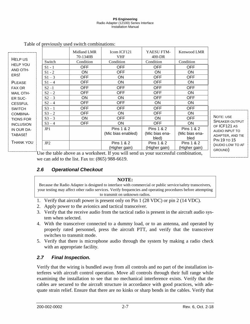
Appendix A- Installation Information and Connector Layout
The Radio Adapter can be installed in any orientation in a convenient location. Mount the
unit using the flanges to a permanent aircraft structure, in accordance with AC 43.13-2B,
Acceptable Methods and Practices, Aircraft Alterations, Chapter 2, Radio Installations.
Rela
y 1 N
CR
ela
y 1 N
O
Gro
un
dA
ud
io G
rou
nd
Aud
io G
rou
nd
Rela
y 2 N
O
Aud
io In
Lo
Mic
A
udio
O
ut
Hi
Aud
io O
ut
Lo
Aud
io O
ut
Hi
No C
onn
ec
t
Rela
y 2 co
mm
on
Rela
y 1 C
om
mo
nG
roun
d
Mic
A
udio
In
Lo
Airc
raft
G
rou
nd
Mic
A
udio
In
H
i
14 V
DC
Rela
y 2 N
C
Key
In
pu
t
Aud
io In
Hi
Mic
A
udio
O
ut
Lo
Airc
raft
G
rou
nd
28V
DC
No C
onn
ec
t
13
25
1211
2423
10
22212019
9876
1817161514
54321
Femal e Harness Connector
Figure 5-1 Connector Layout
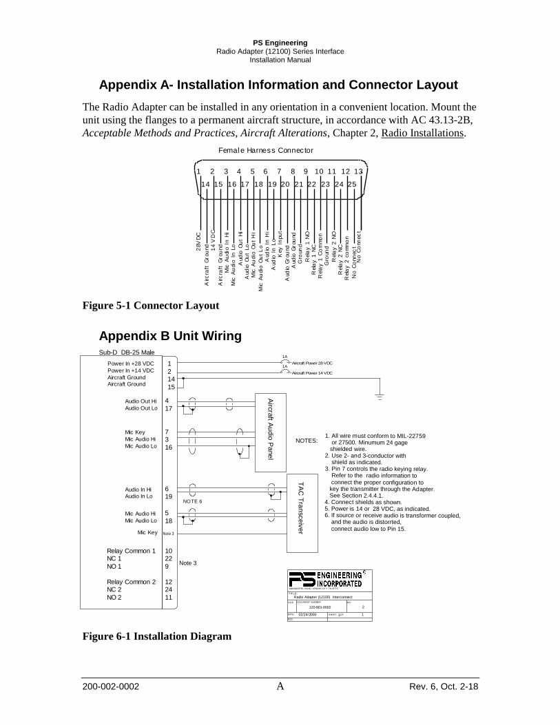
Appendix B Unit Wiring
1A
Aircraft Power 28 VDC1
214
15
Sub-D DB-25 Male
Power In +28 VDC
Power In +14 VDC
Aircraft Ground
Aircraft Ground
Audio Out Hi
Audio Out Lo
4
17
REV
DATE:
ECO
SHEET OF
TITLE:
DOCUMENT NUMBER:SIZE
Radio Adapter (12100) Interconnect
120-801-0002 2
02/24/2000 1 1
9800 MARTEL ROAD, LENOIR CITY TN 37772
1A
Aircraft Power 14 VDC
NOTES:
Mic Key
Mic Audio Hi
Mic Audio Lo
73
16
Airc
raft A
ud
io P
ane
l
Mic Audio Hi
Mic Audio Lo
5
18
Audio In Hi
Audio In Lo
619
TA
C T
ran
sce
ive
rMic Key
1022
9
1224
11
Relay Common 1NC 1
NO 1
Relay Common 2NC 2
NO 2
1. All wire must conform to MIL-22759 or 27500. Minumum 24 gage shielded wire.2. Use 2- and 3-conductor with shield as indicated.3. Pin 7 controls the radio keying relay. Refer to the radio information to connect the proper configuration to key the transmitter through the Adapter. See Section 2.4.4.1.4. Connect shields as shown.5. Power is 14 or 28 VDC, as indicated.6. If source or receive audio is transformer coupled, and the audio is distorrted, connect audio low to Pin 15.
Note 3
Note 3
NOTE 6
Figure 6-1 Installation Diagram

PS Engineering Radio Adapter (12100) Series Interface
Installation Manual
200-002-0002 B Rev. 6, Oct. 2-18
Appendix C -Instructions for Continuing Airworthiness
The Radio Adapter (12100) is considered an “on-condition” maintenance item. It
should be checked prior to each flight during normal operation. There are no additional
considerations for continuing airworthiness other than the practices detailed in AC 43.13-
1B, Chapter 11. This includes inspecting the unit to be sure it is securely fastened in its
location, and that the wiring harness is not chafed or pinched, and remains secure. All
connections should be checked at each periodic inspection to ensure that they are tight
and not in contact with other items in the aircraft.