Part No: FXUB63.07 - Taoglas - Antenna Solutions - 2G, … Page 1 of 15 SPECIFICATION PATENT PENDING...
15
SPE-14-8-054/B/RC Page 1 of 15 SPECIFICATION PATENT PENDING Part No: FXUB63.07.0150C Product Name: LTE Wide Band Flex Antenna 698MHz -3000 MHz Features: Patent Pending Ground Plane Independent 698-3000 MHz >45% Efficiency on All bands 5 dBi Peak Gain 96*21*0.2 mm size IPEX MHFI (U.FL Compatible) RoHS Compliant
Transcript of Part No: FXUB63.07 - Taoglas - Antenna Solutions - 2G, … Page 1 of 15 SPECIFICATION PATENT PENDING...

SPE-14-8-054/B/RC Page 1 of 15
SPECIFICATION
PATENT PENDING
Part No: FXUB63.07.0150C
Product Name: LTE Wide Band Flex Antenna 698MHz -3000 MHz
Features: Patent Pending
Ground Plane Independent
698-3000 MHz
>45% Efficiency on All bands
5 dBi Peak Gain
96*21*0.2 mm size
IPEX MHFI (U.FL Compatible)
RoHS Compliant
SPE-14-8-054/B/RC Page 2 of 15
1. INTRODUCTION
The patent pending FXUB63 flexible ultra wideband antenna has been designed to cover all
working frequencies in the 698-3000 MHz spectrum, covering all Cellular, 2.4GHz Wi-Fi, ISM and
AGPS. The antenna is delivered with a flexible body with excellent efficiencies on all bands,
ground independent, with cable and connector for easy installation.
The FXUB63 flexible polymer antenna, at 96*21*0.2mm, is ultra thin and truly ultra wideband
with high efficiencies across the bands. It is assembled by a simple “peel and stick” process,
attaching securely to non-metal surfaces via 3M adhesive. It enables designers to use only one
antenna that covers all common LTE frequencies.
The FXUB63 antenna is a durable flexible polymer antenna that has a peak gain of 5dBi, an
efficiency of more than 45% across the bands and is designed to be mounted directly onto a
plastic or glass cover. It is an ideal choice for any device maker that needs to keep
manufacturing costs down over the lifetime of a product. It is ground plane independent and
delivered with a cable and connector for easy connecting to the wireless module or customer
PCB.
Cables and Connectors are customizable. Like all such antennas, care should be taken to mount
the antenna at least 10mm from metal components or surfaces, and ideally 20mm for best
Radiation efficiency.

SPE-14-8-054/B/RC Page 3 of 15
2. SPECIFICATION
Band 700/850/
900 1575
1700/1800/
1900 2100 2400 2600
Standard CELL GPS CELL CELL ISM CELL
Frequency (MHz) 698-960 1575.42 1710-1990 1755-2170
2400-2500 2500-2690
Max VSWR 2:1 2:1 1.8:1 1.7:1 1.7:1 2.3:1
Max Return Loss (dB) -10 -10 -11 -12 -12 -8
Peak Gain (dBi) 1 2.5 3.5 5 5 4.5
Efficiency (%) 50 75 78 65 75 75
Average Gain (dB) -3 -2 -2 -2.5 -2 -2
Radiation Properties Omni-directional
Max Input Power (Watts)
5
Polarization Linear
Impedance (Ohms) 50 Ohms
*Antenna measured on plastic plate of 3 mm thickness.
MECHANICAL
Dimensions (mm) 96*21*0.2 mm
Material Flexible Polymer
Connector and Cable U.FL and 1.37 mm mini coax
Cable Length 150 mm
ENVIRONMENTAL
Operation Temperature -40°C to 85°C
Storage Temperature -40°C to 85°C
Relative Humidity 40% to 95%
RoHs Compliant Yes
SPE-14-8-054/B/RC Page 4 of 15
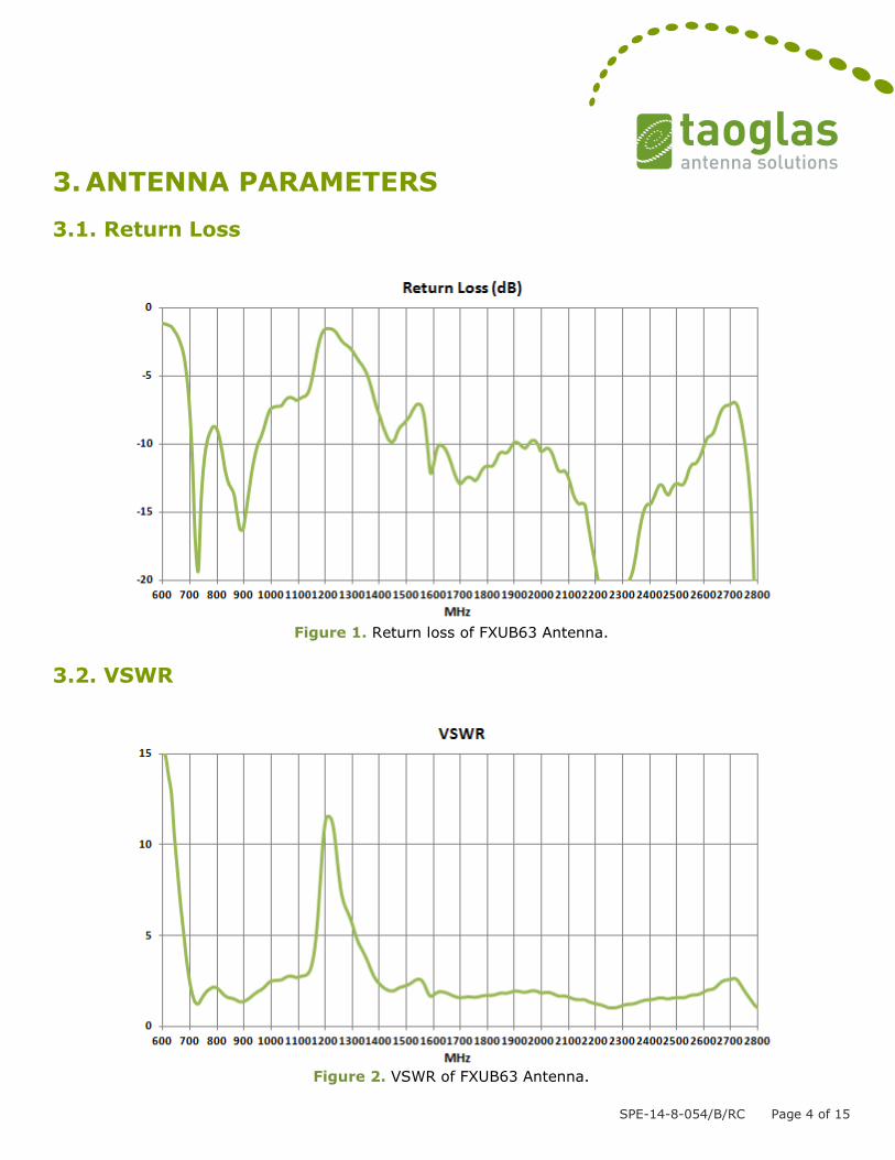
3. ANTENNA PARAMETERS
3.1. Return Loss
Figure 1. Return loss of FXUB63 Antenna.
3.2. VSWR
Figure 2. VSWR of FXUB63 Antenna.

SPE-14-8-054/B/RC Page 5 of 15
3.3. Peak Gain
Figure 3. Peak Gain of FXUB63 Antenna.
3.4. Efficiency
Figure 4. Efficiency of FXUB63 Antenna.

SPE-14-8-054/B/RC Page 6 of 15
3.5. Average Gain
Figure 5. Average Gain of FXUB63 Antenna.
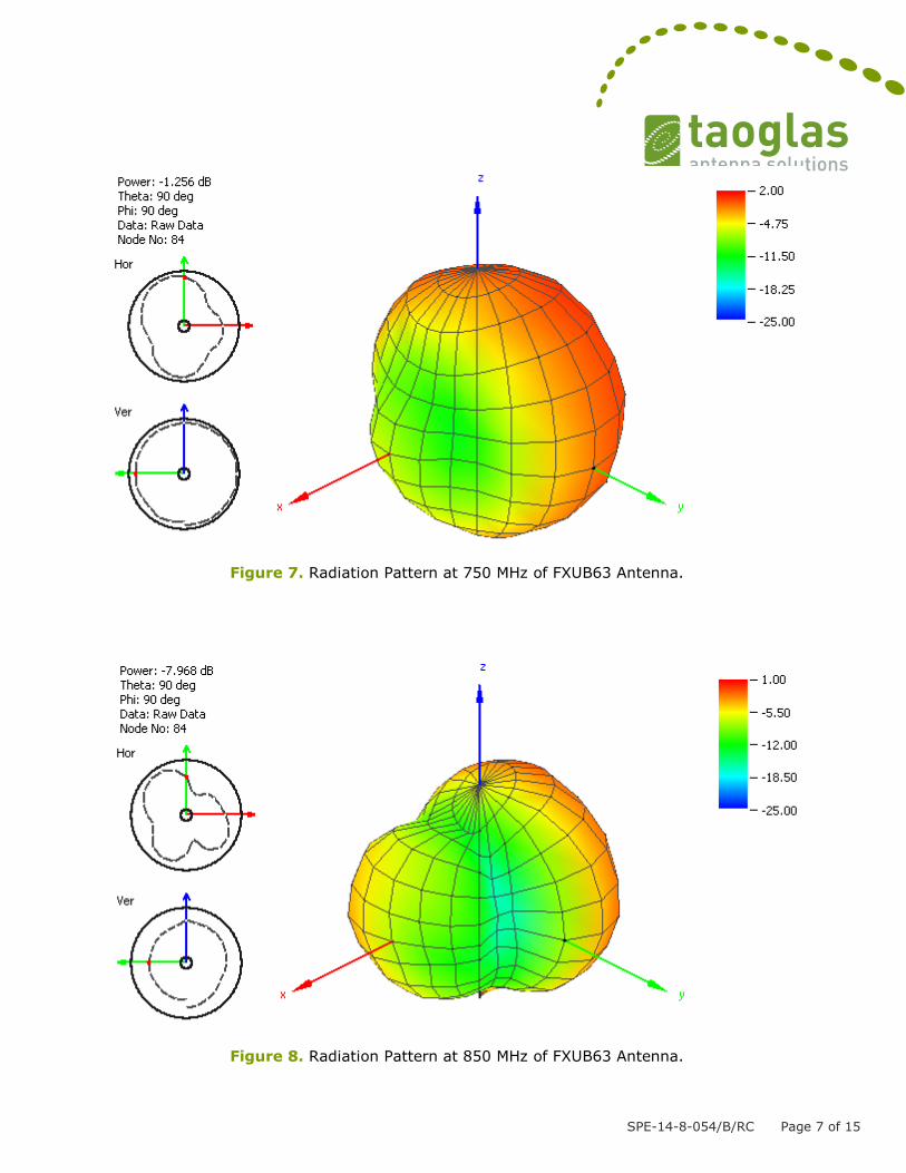
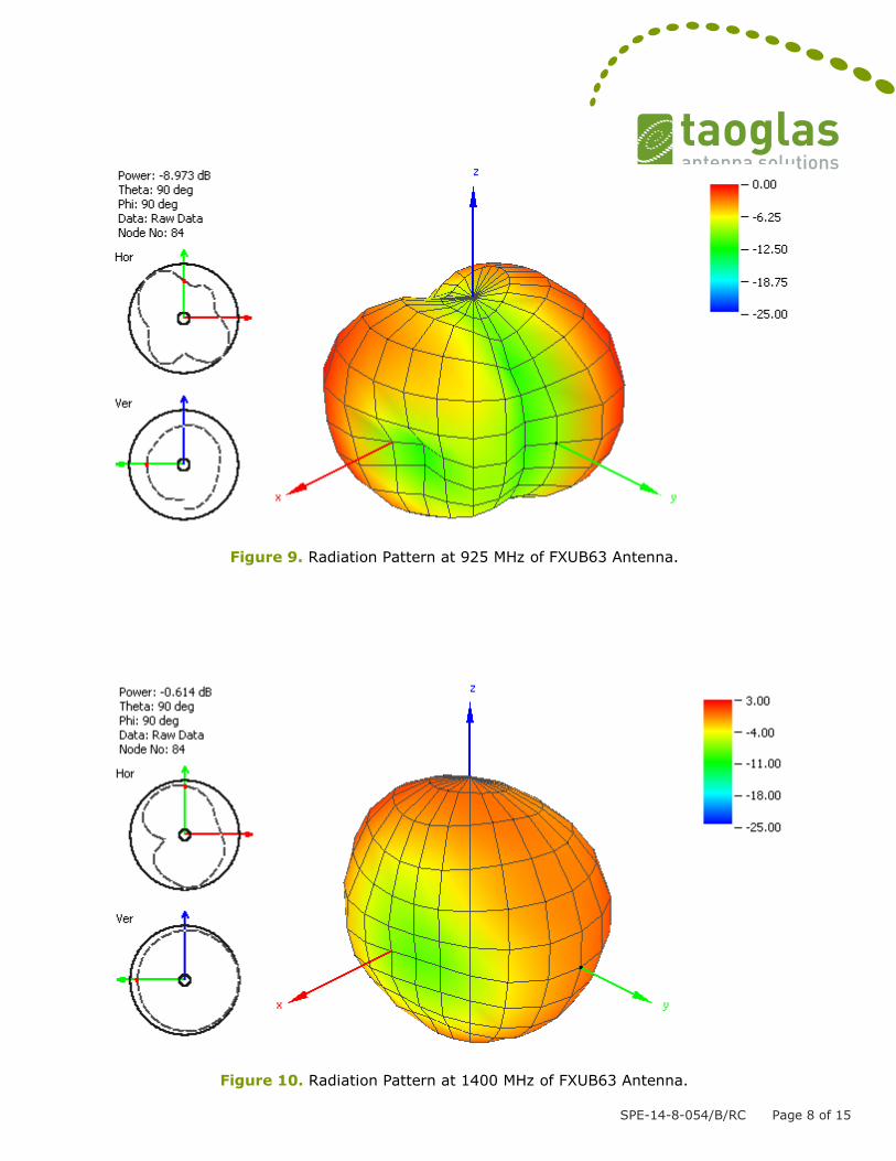
3.6. Radiation Pattern
Figure 6. Radiation Pattern Reference of FXUB63 Antenna.
X
Z
Y
SPE-14-8-054/B/RC Page 7 of 15
Figure 7. Radiation Pattern at 750 MHz of FXUB63 Antenna.
Figure 8. Radiation Pattern at 850 MHz of FXUB63 Antenna.
SPE-14-8-054/B/RC Page 8 of 15
Figure 9. Radiation Pattern at 925 MHz of FXUB63 Antenna.
Figure 10. Radiation Pattern at 1400 MHz of FXUB63 Antenna.
SPE-14-8-054/B/RC Page 9 of 15
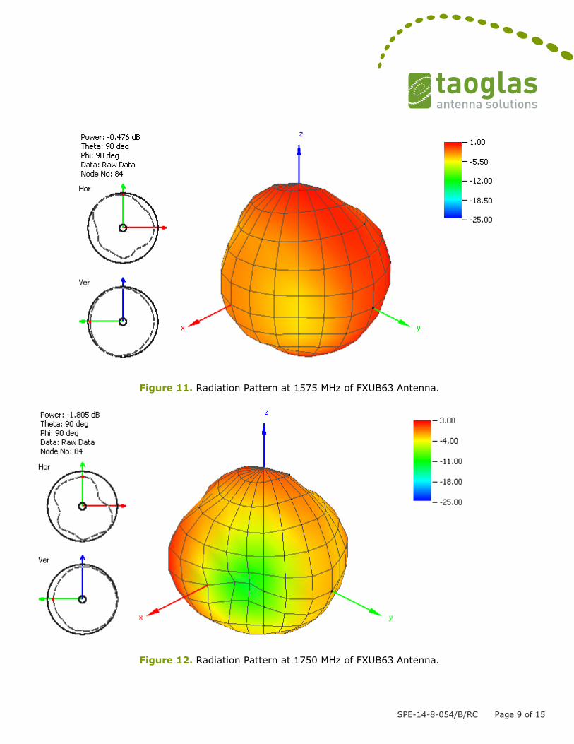
Figure 11. Radiation Pattern at 1575 MHz of FXUB63 Antenna.
Figure 12. Radiation Pattern at 1750 MHz of FXUB63 Antenna.

SPE-14-8-054/B/RC Page 10 of 15
Figure 13. Radiation Pattern at 1850 MHz of FXUB63 Antenna.
Figure 14. Radiation Pattern at 1950 MHz of FXUB63 Antenna.
SPE-14-8-054/B/RC Page 11 of 15
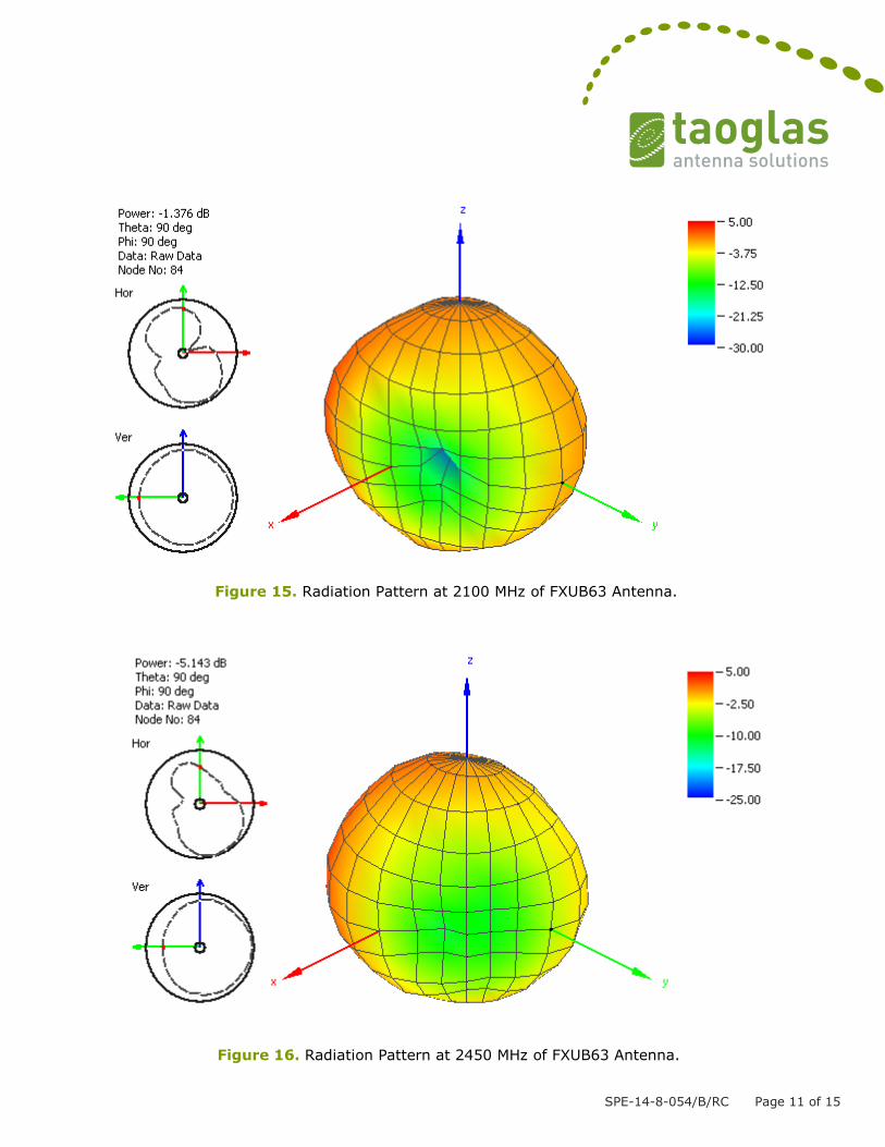
Figure 15. Radiation Pattern at 2100 MHz of FXUB63 Antenna.
Figure 16. Radiation Pattern at 2450 MHz of FXUB63 Antenna.

SPE-14-8-054/B/RC Page 12 of 15
Figure 17. Radiation Pattern at 2600 MHz of FXUB63 Antenna.

SPE-14-8-054/B/RC Page 13 of 15
4. MECHANICAL DRAWING
Figure 18. Mechanical drawing of FXUB63 Antenna.

SPE-14-8-054/B/RC Page 14 of 15
5. Packaging

SPE-14-8-054/B/RC Page 15 of 15
Taoglas makes no warranties based on the accuracy or completeness of the contents of this document and reserves
the right to make changes to specifications and product descriptions at any time without notice.
Taoglas reserves all rights to this document and the information contained herein. Reproduction, use or disclosure to
third parties without express permission is strictly prohibited.
Copyright © Taoglas Ltd.