Part No. : FXR.05 - Taoglas - Antenna Solutions - 2G, 3G ... Page 1 of 10 SPECIFICATION Part No. :...
10
SPE-14-8-073/E/CM Page 1 of 10 SPECIFICATION Part No. : FXR.05.A Product Name : Small Form Factor Circular Flexible Near-Field Communications Antenna Features : 13.56 MHz Flexible Low Profile Embedded Dimensions: • Diameter: 26.4 mm • Thickness: 0.24 mm Peel and stick 3M adhesive on back RoHS Compliant
Transcript of Part No. : FXR.05 - Taoglas - Antenna Solutions - 2G, 3G ... Page 1 of 10 SPECIFICATION Part No. :...

SPE-14-8-073/E/CMPage1of10
SPECIFICATION
Part No. : FXR.05.A
Product Name : Small Form Factor Circular Flexible Near-Field
Communications Antenna
Features : 13.56 MHz
Flexible Low Profile Embedded
Dimensions:
• Diameter: 26.4 mm
• Thickness: 0.24 mm
Peel and stick 3M adhesive on back
RoHS Compliant

SPE-14-8-073/E/CMPage2of10
1. Introduction
The FXR.05.A is a rectangular, flexible, NFC (Near Field Communications) antenna
for use in mobile devices and other applications. The antenna can be directly adhered
to the plastic enclosure of the device for ease of installation.
With NFC antennas being commonly attached to the battery of mobile devices, they
can be customized with a ferrite flux director to provide isolation from the battery or
other components within the device. Using the antenna on a conductive surface
without a ferrite layer will result in extremely short range or complete failure to
communicate.
Customized antennas for specific applications for shape and for impedance match can
also be provided for an NRE and subject to MOQ. Contact your regional Taoglas sales
office for more information and support on our NFC antenna range.
SPE-14-8-073/E/CMPage3of10
2. Specifications
Flexible PCB Near-Field Communications Antenna Frequency 13.56 MHz
Inductance @ 13.56 MHz 15.9 µH
Mechanical Antenna Dimensions Diameter: 26.4 mm; Thickness: 0.24 mm
RoHS Compliant Yes Adhesive 3M 467 Weight 201.7mg
Environmental
Operation Temperature -40°C to 85°C Storage Temperature -40°C to 85°C
Humidity Non-condensing 65°C 95% RH
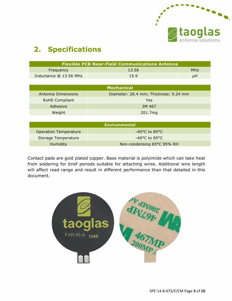
Contact pads are gold plated copper. Base material is polyimide which can take heat from soldering for brief periods suitable for attaching wires. Additional wire length will affect read range and result in different performance than that detailed in this document.

SPE-14-8-073/E/CMPage4of10
3. Antenna Application
3.1. Test setup
A test fixture is used to measure the maximum interrogation distance. The FXR.05.A antenna is connected to different NFC evaluation boards and then placed on the fixed part of the fixture.
The test sample is placed on a thin sheet of plastic connected to the movable part of the fixture. Then the distance is carefully adjusted until the reader can no longer read the sample, thus the maximum interrogation distance is displayed in the ruler.
Testsample
Antenna
Evaluation board
Ruler
Test fixture

SPE-14-8-073/E/CMPage5of10
3.2. RFID tags used for test
A total of 10 RFID tags were used to measure the interrogation distances. The next picture shows type 1, type 2 and type 4 tags, respectively.
Type 1 tag is based on ISO/IEC 14443A standard and has 512 bytes of memory. Type 2 tag is based on ISO/IEC 14443A standard and has 192 bytes of memory. Type 4 is based on ISO / IEC 14443A 1-4 compliant and has 2K of memory. The next picture shows the Tag-it HF-I RFID tags from Texas Instruments: RI-102-112, RI-I11-112, RI-I03-112, RI-I16-112, Button and RI-I17-112.
The Tag-it HF-I Plus Transponder Inlay family of Texas Instruments RFID is based on the ISO/IEC 15693 standard for contactless integrated circuit cards (vicinity cards) and ISO/IEC 18000-3 standard for item management.

SPE-14-8-073/E/CMPage6of10
3.3. Matching
The interrogation distances presented here were taken with the antenna connected directly to the evaluation boards with the default matching circuit. This is not necessarily the optimal matching circuit that could be designed for a particular antenna. We kept the default matching of each evaluation board to minimize the number of variables in testing and keep integration as simple as possible.
As with any matching network the exact circuit and values for an optimal network depend on the combination of antenna, NFC circuit, any intervening transmission line, and the environment presented to the antenna. These factors are specific to the particular end product.
As a starting point, to achieve the read range results presented here, use the matching network detailed in the schematic of the evaluation board for your particular NFC chip and keep the antenna free of any obstruction. Once you can demonstrate successful reads you can then optimize performance as desired.

SPE-14-8-073/E/CMPage7of10
3.4. Test results
A total of 11 sample devices were used to measure the interrogation distances. The results are in the next tables:
• Using Texas Instruments TRF7970AEVM:
Device Dimensions (mm.)
Interrogation Distance (mm.)
Mifare Ultralight C 80 x 50 10 Topaz512 (Type 1) 43 x 43 16 NTAG203 (Type 2) F 42 21 Mifare DESFire (Type 4) 80 x 50 15 Tag-it HFI Plus RI-I11-112 45 x 45 27 Tag-it HFI Plus RI-I02-112 76 x 48 35 Tag-it HFI Plus RI-I03-112 38 x 22.5 26 Tag-it HFI Plus RI-I16-112 F 24.2 24 Button type F 22 23 Tag-it HFI Plus RI-I17-112 F 32.5 25 LG G2 cell phone -- 22
• Using NXP MFEV700:
Device Dimensions (mm.)
Interrogation Distance (mm.)
Mifare Ultralight C 80 x 50 -- Mifare DESFire (Type 4) 80 x 50 -- LG G2 cell phone -- 7
SPE-14-8-073/E/CMPage8of10
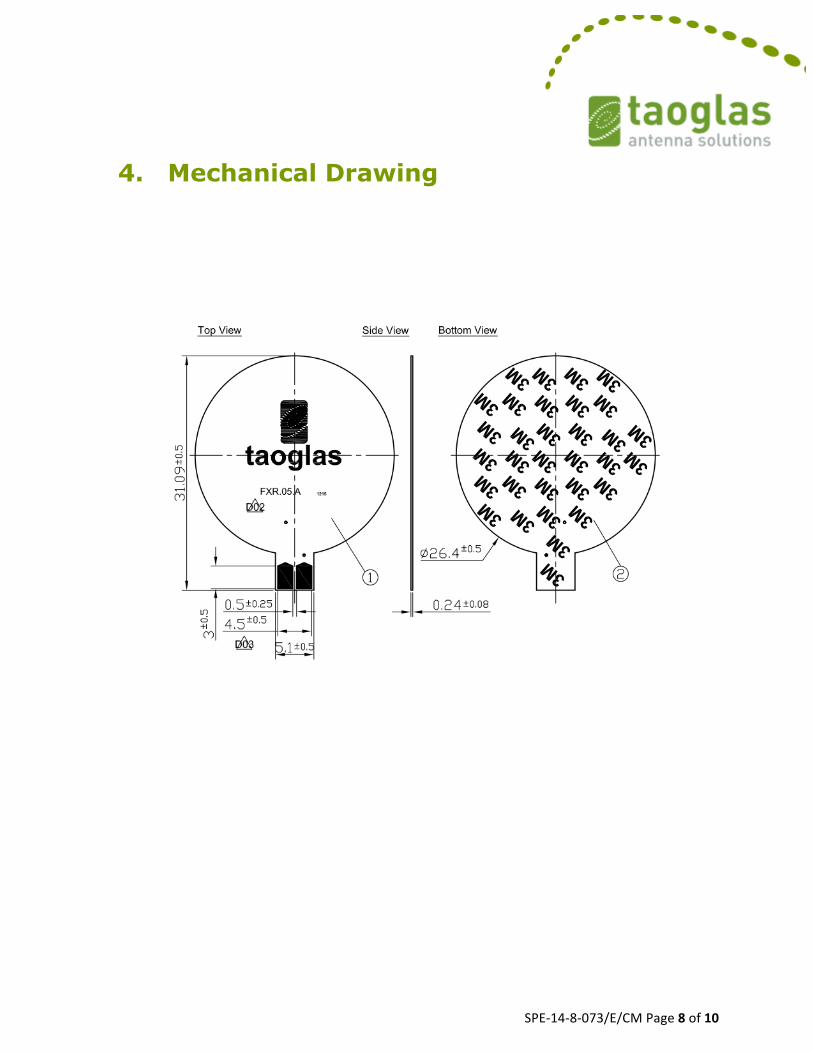
4. Mechanical Drawing

SPE-14-8-073/E/CMPage9of10
5. Packaging

SPE-14-8-073/E/CMPage10of10
Taoglasmakesnowarrantiesbasedontheaccuracyorcompletenessofthecontentsofthisdocumentandreservestherighttomakechangestospecificationsandproductdescriptionsatanytimewithoutnotice.Taoglasreservesallrightstothisdocumentandtheinformationcontainedherein.
Reproduction,useordisclosuretothirdpartieswithoutexpresspermissionisstrictlyprohibited.
Copyright©TaoglasLtd.