
PART I EMC Theory - John Wiley & Sons€¦ · EMC engineering can be approached in either of two...
43
PART I EMC Theory COPYRIGHTED MATERIAL
Transcript of PART I EMC Theory - John Wiley & Sons€¦ · EMC engineering can be approached in either of two...
PART I
EMC Theory
COPYRIG
HTED M
ATERIAL

1 Electromagnetic Compatibility
1.1 INTRODUCTION
The widespread use of electronic circuits for communication, computation,automation, and other purposes makes it necessary for diverse circuits tooperate in close proximity to each other. All too often, these circuits affect eachother adversely. Electromagnetic interference (EMI) has become a majorproblem for circuit designers, and it is likely to become even more severe inthe future. The large number of electronic devices in common use is partlyresponsible for this trend. In addition, the use of integrated circuits and large-scale integration has reduced the size of electronic equipment. As circuitry hasbecome smaller and more sophisticated, more circuits are being crowded intoless space, which increases the probability of interference. In addition, clockfrequencies have increased dramatically over the years—in many cases to overa gigahertz. It is not uncommon today for personal computers used in the hometo have clock speeds in excess of 1 GHz.
Today’s equipment designers need to do more than just make their systemsoperate under ideal conditions in the laboratory. Besides that obvious task,products must be designed to work in the ‘‘real world,’’ with other equipmentnearby, and to comply with government electromagnetic compatibility (EMC)regulations. This means that the equipment should not be affected by externalelectromagnetic sources and should not itself be a source of electromagneticnoise that can pollute the environment. Electromagnetic compatibility shouldbe a major design objective.
1.2 NOISE AND INTERFERENCE
Noise is any electrical signal present in a circuit other than the desired signal. Thisdefinition excludes the distortion products produced in a circuit due tononlinearities. Although these distortion products may be undesirable, theyare not considered noise unless they are coupled into another part of the circuit.It follows that a desired signal in one part of a circuit can be considered to benoise when coupled to some other part of the circuit.
Electromagnetic Compatibility Engineering, by Henry W. OttCopyright r 2009 John Wiley & Sons, Inc.

Noise sources can be grouped into the following three categories: (1) intrinsicnoise sources that arise from random fluctuations within physical systems, suchas thermal and shot noise; (2) man-made noise sources, such as motors,switches, computers, digital electronics, and radio transmitters; and (3) noisecaused by natural disturbances, such as lightning and sunspots.
Interference is the undesirable effect of noise. If a noise voltage causesimproper operation of a circuit, it is interference. Noise cannot be eliminated,but interference can. Noise can only be reduced in magnitude, until it no longercauses interference.
1.3 DESIGNING FOR ELECTROMAGNETIC COMPATIBILITY
Electromagnetic compatibility (EMC) is the ability of an electronic system to(1) function properly in its intended electromagnetic environment and (2) not bea source of pollution to that electromagnetic environment. The electromagneticenvironment is composed of both radiated and conducted energy. EMCtherefore has two aspects, emission and susceptibility.
Susceptibility is the capability of a device or circuit to respond to unwantedelectromagnetic energy (i.e., noise). The opposite of susceptibility is immunity.The immunity level of a circuit or device is the electromagnetic environment inwhich the equipment can operate satisfactorily, without degradation, and witha defined margin of safety. One difficulty in determining immunity (orsusceptibility) levels is defining what constitutes performance degradation.
Emission pertains to the interference-causing potential of a product. Thepurpose of controlling emissions is to limit the electromagnetic energy emittedand thereby to control the electromagnetic environment in which otherproducts must operate. Controlling the emission from one product mayeliminate an interference problem for many other products. Therefore, it isdesirable to control emission in an attempt to produce an electromagneticallycompatible environment.
To some extent, susceptibility is self-regulating. If a product is susceptible tothe electromagnetic environment, the user will become aware of it and may notcontinue to purchase that product. Emission, however, tends not to be self-regulating. A product that is the source of emission may not itself be affected bythat emission. To guarantee that EMC is a consideration in the design of allelectronic products, various government agencies and regulatory bodies haveimposed EMC regulations that a product must meet before it can be marketed.These regulations control allowable emissions and in some cases define thedegree of immunity required.
EMC engineering can be approached in either of two ways: one is the crisisapproach, and the other is the systems approach. In the crisis approach, thedesigner proceeds with a total disregard of EMC until the functional design isfinished, and testing—or worse yet—field experience suggests that a problem
4 ELECTROMAGNETIC COMPATIBILITY
exists. Solutions implemented at this late stage are usually expensive and consistof undesirable ‘‘add ons.’’ This is often referred to as the ‘‘Band Aid’’ approach.
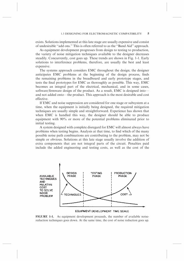
As equipment development progresses from design to testing to production,the variety of noise mitigation techniques available to the designer decreasessteadily. Concurrently, cost goes up. These trends are shown in Fig. 1-1. Earlysolutions to interference problems, therefore, are usually the best and leastexpensive.
The systems approach considers EMC throughout the design; the designeranticipates EMC problems at the beginning of the design process, findsthe remaining problems in the breadboard and early prototype stages, andtests the final prototypes for EMC as thoroughly as possible. This way, EMCbecomes an integral part of the electrical, mechanical, and in some cases,software/firmware design of the product. As a result, EMC is designed into—and not added onto—the product. This approach is the most desirable and costeffective.
If EMC and noise suppression are considered for one stage or subsystem at atime, when the equipment is initially being designed, the required mitigationtechniques are usually simple and straightforward. Experience has shown thatwhen EMC is handled this way, the designer should be able to produceequipment with 90% or more of the potential problems eliminated prior toinitial testing.
A system designed with complete disregard for EMC will almost always haveproblems when testing begins. Analysis at that time, to find which of the manypossible noise path combinations are contributing to the problem, may not besimple or obvious. Solutions at this late stage usually involve the addition ofextra components that are not integral parts of the circuit. Penalties paidinclude the added engineering and testing costs, as well as the cost of the
FIGURE 1-1. As equipment development proceeds, the number of available noise-
reduction techniques goes down. At the same time, the cost of noise reduction goes up.
1.3 DESIGNING FOR ELECTROMAGNETIC COMPATIBILITY 5
mitigation components and their installation. There also may be size, weight,and power dissipation penalties.
1.4 ENGINEERING DOCUMENTATION AND EMC
As the reader will discover, much of the information that is important forelectromagnetic compatibility is not conveyed conveniently by the standardmethods of engineering documentation, such as schematics, and so on. Forexample, a ground symbol on a schematic is far from adequate to describewhere and how that point should be connected. Many EMC problems involveparasitics, which are not shown on our drawings. Also, the components shownon our engineering drawings have remarkably ideal characteristics.
The transmission of the standard engineering documentation alone istherefore insufficient. Good EMC design requires cooperation and discussionamong the complete design team, the systems engineer, the electrical engineer,the mechanical engineer, the EMC engineer, the software/firmware designer,and the printed circuit board designer.
In addition, many computer-assisted design (CAD) tools do not includesufficient, if any, EMC considerations. EMC considerations therefore mustoften be applied manually by overriding the CAD system. Also, you and yourprinted circuit designer often have different objectives. Your objective is, orshould be, to design a system that works properly and meets EMC require-ments. Your printed circuit board (PCB) designer has the objective of doingwhat ever has to be done to fit all the components and traces on the boardregardless of the EMC implications.
1.5 UNITED STATES’ EMC REGULATIONS
Added insight into the problem of interference, as well as the obligations ofequipment designers, manufacturers, and users of electronic products, can begained from a review of some of the more important commercial and militaryEMC regulations and specifications.
The most important fact to remember about EMC regulations is that theyare ‘‘living documents’’ and are constantly being changed. Therefore, a 1-year-old version of a standard or regulation may no longer be applicable. Whenworking on a new design project, always be sure to have copies of the mostrecent versions of the applicable regulations. These standards may actuallyeven change during the time it takes to design the product.
1.5.1 FCC Regulations
In the United States, the Federal Communications Commission (FCC)regulates the use of radio and wire communications. Part of its responsibility
6 ELECTROMAGNETIC COMPATIBILITY
concerns the control of interference. Three sections of the FCC Rules andRegulations* have requirements that are applicable to nonlicensed electronicequipment. These requirements are contained in Part 15 for radio frequencydevices; Part 18 for industrial, scientific, and medical (ISM) equipment; andPart 68 for terminal equipment connected to the telephone network.
Part 15 of the FCC Rules and Regulations sets forth technical standards andoperational requirements for radio frequency devices. A radio-frequency deviceis any device that in its operation is capable of emitting radio-frequency energy byradiation, conduction, or other means (y 2.801). The radio-frequency energymay be emitted intentionally or unintentionally. Radio-frequency (rf) energy isdefined by the FCC as any electromagnetic energy in the frequency range of 9kHz to 3000 GHz (y15.3(u)). The Part 15 regulations have a twofold purpose:(1) to provide for the operation of low-power transmitters without a radiostation license and (2) to control interference to authorized radio communica-tions services that may be caused by equipment that emits radio-frequencyenergy or noise as a by-product to its operation. Digital electronics fall into thelatter category.
Part 15 is organized into six parts. Subpart A—General, Subpart B—Unintentional Radiators, Subpart C—Intentional Radiators, Subpart D—Unlicensed Personal Communications Devices, Subpart E—UnlicensedNational Information Infrastructure Devices, and Subpart F—Ultra-Wide-band Operation. Subpart B contains the EMC Regulations for electronicdevices that are not intentional radiators.
Part 18 of the FCC Rules and Regulations sets forth technical standards andoperational conditions for ISM equipment. ISM equipment is defined as anydevice that uses radio waves for industrial, scientific, medical, or other purposes(including the transfer of energy by radio) and that is neither used nor intendedto be used for radio communications. Included are medical diathermy equip-ment, industrial heating equipment, rf welders, rf lighting devices, devices thatuse radio waves to produce physical changes in matter, and other similar non-communications devices.
Part 68 of the FCC Rules and Regulations provides uniform standards forthe protection of the telephone network from harm caused by connection ofterminal equipment [including private branch exchange (PBX) systems] and itswiring, and for the compatibility of hearing aids and telephones to ensure thatpersons with hearing aids have reasonable access to the telephone network.Harm to the telephone network includes electrical hazards to telephonecompany workers, damage to telephone company equipment, malfunction oftelephone company billing equipment, and degradation of service to personsother than the user of the terminal equipment, his calling or called party.
In December 2002, the FCC released a Report and Order (Docket 99-216)privatizing most of Part 68, with the exception of the requirements on hearing
*Code of Federal Regulations, Title 47, Telecommunications.
1.5 UNITED STATES’ EMC REGULATIONS 7

aid compatibility. Section 68.602 of the FCC rules authorized the Telecommu-nications Industry Association (TIA) to establish the Administrative Councilfor Terminal Attachments (ACTA) with the responsibility of defining andpublishing technical criteria for terminal equipment connected to the U.S.public telephone network. These requirements are now defined in TIA-968. Thelegal requirement for all terminal equipment to comply with the technicalstandards, however, remains within Part 68 of the FCC rules. Part 68 requiresthat terminal equipment connected directly to the public switched telephonenetwork meet both the criteria of Part 68 and the technical criteria published byACTA.
Two approval processes are available to the manufacturer of telecommunica-tions terminal equipment, as follows: (1) The manufacturer can provide aDeclaration of Conformity (y68.320) and submit it to ACTA, or (2) themanufacturer can have the equipment certified by a Telecommunications Certify-ing Body (TCB) designated by the Commission (y68.160). The TCB must beaccredited by the National Institute of Standards and Technology (NIST).
1.5.2 FCC Part 15, Subpart B
The FCC rule with the most general applicability is Part 15, Subpart B becauseit applies to virtually all digital electronics. In September 1979, the FCCadopted regulations to control the interference potential of digital electronics(at that time called ‘‘computing devices’’). These regulations, ‘‘TechnicalStandards for Computing Equipment’’ (Docket 20780); amended Part 15 ofthe FCC rules relating to restricted radiation devices. The regulations are nowcontained in Part 15, Subpart B of Title 47 of the Code of Federal Regulations.Under these rules, limits were placed on the maximum allowable radiatedemission and on the maximum allowable conducted emission on the alternatingcurrent (ac) power line. These regulations were the result of increasingcomplaints to the FCC about interference to radio and television receptionwhere digital electronics were identified as the source of the interference. In thisruling the FCC stated the following:
Computers have been reported to cause interference to almost all radio services,
particularly those services below 200MHz,* including police, aeronautical, and
broadcast services. Several factors contributing to this include: (1) digital equip-
ment has become more prolific throughout our society and are now being sold for
use in the home; (2) technology has increased the speed of computers to the point
where the computer designer is now working with radio frequency and electro-
magnetic interference (EMI) problems—something he didn’t have to contend with
15 years ago; (3) modern production economics has replaced the steel cabinets
which shield or reduce radiated emanations with plastic cabinets which provide
little or no shielding.
*Remember this was 1979.
8 ELECTROMAGNETIC COMPATIBILITY

In the ruling, the FCC defined a digital device (previously called a computingdevice) as follows:
An unintentional radiator (device or system) that generates and uses timing signals
or pulses at a rate in excess of 9000 pulses (cycles) per second and uses digital
techniques; inclusive of telephone equipment that uses digital techniques or any
device or system that generates and uses radio frequency energy for the purpose of
performing data processing functions, such as electronic computations, operations,
transformations, recording, filing, sorting, storage, retrieval or transfer (y 15.3(k)).
Computer terminals and peripherals, which are intended to be connected toa computer, are also considered to be digital devices.
This definition was intentionally broad to include as many products aspossible. Thus, if a product uses digital circuitry and has a clock greater than 9kHz, then it is a digital device under the FCC definition. This definition coversmost digital electronics in existence today.
Digital devices covered by this definition are divided into the following twoclasses:
Class A: A digital device that is marketed for use in a commercial, industrial,or business environment (y 15.3(h)).
Class B: A digital device that is marketed for use in a residential environ-ment, notwithstanding use in commercial, business, and industrial en-vironments (y 15.3(i)).
Because Class B digital devices are more likely to be located in closerproximity to radio and television receivers, the emission limits for these devicesare about 10 dB more restrictive than those for Class A devices.
Meeting the technical standards contained in the regulations is the obligationof the manufacturer or importer of a product. To guarantee compliance, theFCC requires the manufacturer to test the product for compliance beforethe product can be marketed in the United States. The FCC defines marketingas shipping, selling, leasing, offering for sale, importing, and so on (y 15.803(a)).Until a product complies with the rules, it cannot legally be advertised ordisplayed at a trade show, because this would be considered an offer for sale.To advertise or display a product legally prior to compliance, the advertisementor display must contain a statement worded as follows:
This device has not been authorized as required by the rules of the Federal
Communications Commission. This device is not, and may not be, offered for sale
or lease, or sold or leased, until authorization is obtained (y 2.803(c)).
For personal computers and their peripherals (a subcategory of Class B), themanufacturer can demonstrate compliance with the rules by a Declaration ofConformity. A Declaration of Conformity is a procedure where the manufac-turer makes measurements or takes other steps to ensure that the equipment
1.5 UNITED STATES’ EMC REGULATIONS 9

complies with the applicable technical standards (y 2.1071 to 2.1077). Submis-sion of a sample unit or representative test data to the FCC is not requiredunless specifically requested.
For all other products (Class A and Class B—other than personal computersand their peripherals), the manufacturer must verify compliance by testingthe product before marketing. Verification is a self-certification procedurewhere nothing is submitted to the FCC unless specifically requested by theCommission, which is similar to a declaration of conformity (y 2.951 to 2.956).Compliance is by random sampling of products by the FCC. The time requiredto do the compliance tests (and to fix the product, and redo the test if the productfails) should be scheduled into the product’s development timetable. Precom-pliance EMC measurements (see Chapter 18) can help shorten this timeconsiderably.
Testing must be performed on a sample that is representative of productionunits. This usually means an early production or preproduction model. Finalcompliance testing must therefore be one of the last items in the productdevelopment timetable. This is no time for unexpected surprises! If a productfails the compliance test, then changes at this point are difficult, time consuming,and expensive. Therefore, it is desirable to approach the final compliance test witha high degree of confidence that the product will pass. This can be done if (1)proper EMC design principles (as described in this book) have been usedthroughout the design and (2) preliminary pre-compliance EMC testing asdescribed in Chapter 18 was performed on early models and subassemblies.
It should be noted that the limits and the measurement procedures are inter-related. The derived limits were based on specified test procedures. Therefore,compliance measurements must be made following the procedure outlined bythe regulations (y 15.31). The FCC specifies that for digital devices, measure-ments to show compliance with Part 15, must be performed following theprocedures described in measurement standard ANSI C63.4–1992 titled‘‘Methods of Measurement of Radio-Noise Emissions from Low-VoltageElectrical and Electronic Equipment in the Range of 9 kHz to 40 GHz,’’excluding Section 5.7, Section 9, and Section 14 (y 15.31(a)(6)).*
The test must be made on a complete system, with all cables connected andconfigured in a reasonable way that tends to maximize the emission (y 15.31(i)).Special authorization procedures are provided in the case of central processorunit (CPU) boards and power supplies that are used in personal computers andsold separately (y 15.32).
* Section 5.7 pertains to the use of an artificial hand to support handheld devices during testing.
Section 9 pertains to measuring radio-noise power using an absorbing clamp in lieu of radiated
emission measurements for certain restricted frequency ranges and certain types of equipment.
Section 14 pertains to relaxing the radiated and/or conducted emission limits for short duration
(r200 ms) transients.
10 ELECTROMAGNETIC COMPATIBILITY

1.5.3 Emissions
The FCC Part 15 EMC Regulations limit the maximum allowable conductedemission, on the ac power line in the range of 0.150 to 30 MHz, and themaximum radiated emission in the frequency range of 30 MHz to 40 GHz.
1.5.3.1 Radiated Emissions. For radiated emissions, the measurement pro-cedure specifies an open area test site (OATS) or equivalent measurement madeover a ground plane with a tuned dipole or other correlatable, linearly polarizedantenna. This setup is shown in Fig. 1-2. ANSI C63.4 allows for the use of analternative test site, such as an absorber-lined room, provided it meets specifiedsite attenuation requirements. However, a shielded enclosure without absorberlining may not be used for radiated emission measurements.
The specified receive antenna in the 30- to- 1000-MHz range is a tuneddipole, although other linearly polarized broadband antennas may also beused. However, in case of a dispute, data taken with the tuned dipole will takeprecedence. Above 1000 MHz, a linearly polarized horn antenna shall be used.
Table 1-1 lists the FCC radiated emission limits (y 15.109) for a ClassA product when measured at a distance of 10 m. Table 1-2 lists the limits for aClass B product when measured at a distance of 3 m.
FIGURE 1-2. Open area test site (OATS) for FCC radiated emission test. The
equipment under test (EUT) is on the turntable.
1.5 UNITED STATES’ EMC REGULATIONS 11
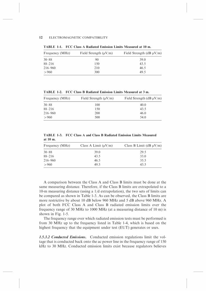
A comparison between the Class A and Class B limits must be done at thesame measuring distance. Therefore, if the Class B limits are extrapolated to a10-m measuring distance (using a 1/d extrapolation), the two sets of limits canbe compared as shown in Table 1-3. As can be observed, the Class B limits aremore restrictive by about 10 dB below 960 MHz and 5 dB above 960 MHz. Aplot of both FCC Class A and Class B radiated emission limits over thefrequency range of 30 MHz to 1000 MHz (at a measuring distance of 10 m) isshown in Fig. 1-5.
The frequency range over which radiated emission tests must be performed isfrom 30 MHz up to the frequency listed in Table 1-4, which is based on thehighest frequency that the equipment under test (EUT) generates or uses.
1.5.3.2 Conducted Emissions. Conducted emission regulations limit the vol-tage that is conducted back onto the ac power line in the frequency range of 150kHz to 30 MHz. Conducted emission limits exist because regulators believes
TABLE 1-2. FCC Class B Radiated Emission Limits Measured at 3 m.
Frequency (MHz) Field Strength (mV/m) Field Strength (dB mV/m)
30–88 100 40.0
88–216 150 43.5
216–960 200 46.0
W960 500 54.0
TABLE 1-3. FCC Class A and Class B Radiated Emission Limits Measured
at 10 m.
Frequency (MHz) Class A Limit (mV/m) Class B Limit (dB mV/m)
30–88 39.0 29.5
88–216 43.5 33.0
216–960 46.5 35.5
W960 49.5 43.5
TABLE 1-1. FCC Class A Radiated Emission Limits Measured at 10 m.
Frequency (MHz) Field Strength (mV/m) Field Strength (dB mV/m)
30–88 90 39.0
88–216 150 43.5
216–960 210 46.5
W960 300 49.5
12 ELECTROMAGNETIC COMPATIBILITY
that at frequencies below 30 MHz, the primary cause of interference with radiocommunications occurs by conducting radio-frequency energy onto the acpower line and subsequently radiating it from the power line. Therefore,conducted emission limits are really radiated emission limits in disguise.
The FCC conducted emission limits (y 15.107) are now the same asthe International Special Committee on Radio Interference (CISPR, from itstitle in French) limits, used by the European Union. This is the result of theCommission amending its conducted emission rules in July 2002 to make themconsistent with the international CISPR requirements.
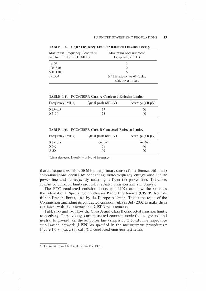
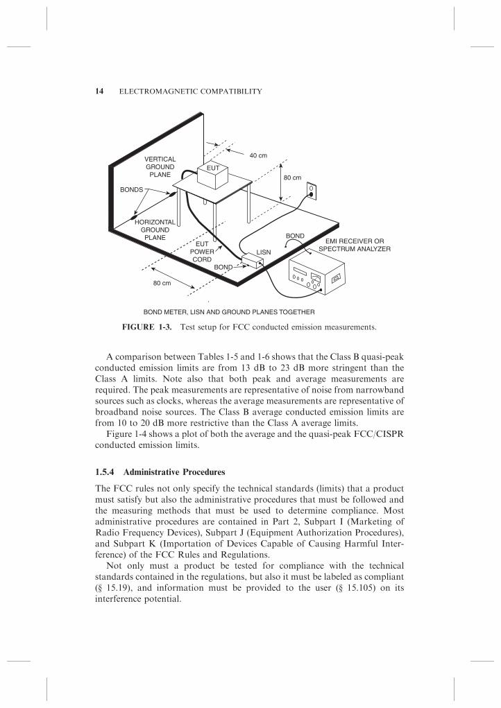
Tables 1-5 and 1-6 show the Class A and Class B conducted emission limits,respectively. These voltages are measured common-mode (hot to ground andneutral to ground) on the ac power line using a 50-O/50-mH line impedancestabilization network (LISN) as specified in the measurement procedures.*Figure 1-3 shows a typical FCC conducted emission test setup.
TABLE 1-6. FCC/CISPR Class B Conducted Emission Limits.
Frequency (MHz) Quasi-peak (dB mV) Average (dB mV)
0.15–0.5 66–56a 56–46a
0.5–5 56 46
5–30 60 50
aLimit decreases linearly with log of frequency.
TABLE 1-5. FCC/CISPR Class A Conducted Emission Limits.
Frequency (MHz) Quasi-peak (dB mV) Average (dB mV)
0.15–0.5 79 66
0.5–30 73 60
TABLE 1-4. Upper Frequency Limit for Radiated Emission Testing.
Maximum Frequency Generated
or Used in the EUT (MHz)
Maximum Measurement
Frequency (GHz)
o108 1
108–500 2
500–1000 5
W1000 5th Harmonic or 40 GHz,
whichever is less
*The circuit of an LISN is shown in Fig. 13-2.
1.5 UNITED STATES’ EMC REGULATIONS 13
A comparison between Tables 1-5 and 1-6 shows that the Class B quasi-peakconducted emission limits are from 13 dB to 23 dB more stringent than theClass A limits. Note also that both peak and average measurements arerequired. The peak measurements are representative of noise from narrowbandsources such as clocks, whereas the average measurements are representative ofbroadband noise sources. The Class B average conducted emission limits arefrom 10 to 20 dB more restrictive than the Class A average limits.
Figure 1-4 shows a plot of both the average and the quasi-peak FCC/CISPRconducted emission limits.
1.5.4 Administrative Procedures
The FCC rules not only specify the technical standards (limits) that a productmust satisfy but also the administrative procedures that must be followed andthe measuring methods that must be used to determine compliance. Mostadministrative procedures are contained in Part 2, Subpart I (Marketing ofRadio Frequency Devices), Subpart J (Equipment Authorization Procedures),and Subpart K (Importation of Devices Capable of Causing Harmful Inter-ference) of the FCC Rules and Regulations.
Not only must a product be tested for compliance with the technicalstandards contained in the regulations, but also it must be labeled as compliant(y 15.19), and information must be provided to the user (y 15.105) on itsinterference potential.
EUT
LISN
HORIZONTALGROUND
PLANE
40 cm
80 cm
EMI RECEIVER ORSPECTRUM ANALYZER
BOND
BOND
80 cm
VERTICALGROUND
PLANE
BOND METER, LISN AND GROUND PLANES TOGETHER
BONDS
EUTPOWERCORD
FIGURE 1-3. Test setup for FCC conducted emission measurements.
14 ELECTROMAGNETIC COMPATIBILITY

In addition to the technical standards mentioned above, the rules alsocontain a noninterference requirement, which states that if use of the productcauses harmful interference, the user may be required to cease operation of thedevice (y 15.5). Note the difference in responsibility between the technicalstandards and the noninterference requirement. Although meeting the technicalstandards (limits) is the responsibility of the manufacturer or importer of theproduct, satisfying the noninterference requirement is the responsibility of theuser of the product.
In addition to the initial testing to determine compliance of a product,the rules also specify that the manufacturer or importer is responsible for thecontinued, or ongoing, compliance of subsequently manufactured units (y 2.953,2.955, 2.1073, 2.1075).
If a change is made to a compliant product, the manufacturer has theresponsibility to determine whether that change has an effect on the complianceof the product. The FCC has cautioned manufacturers (Public Notice 3281,April 7, 1982) to note that:
Many changes, which on their face seem insignificant, are in fact very significant.
Thus a change in the layout of a circuit board, or the addition or removal or even
rerouting of a wire, or even a change in the logic will almost surely change the
emission characteristics of the device. Whether this change in characteristics is
enough to throw the product out of compliance can best be determined by
retesting.
90
80
70
60
50
40
30
VO
LTA
GE
(dB
µV
)
0.1 1 10 100
FREQUENCY (MHz)
CLASS B QUASI-PEAK LIMIT
CLASS A AVERAGE LIMIT
CLASS A QUASI-PEAK LIMIT
CLASS B AVERAGE LIMIT
FIGURE 1-4. FCC/CISPR conducted emission limits.
1.5 UNITED STATES’ EMC REGULATIONS 15

As of this writing (September 2008), the FCC has exempted eight subclassesof digital devices (y 15.103) from meeting the technical standards of the rules.These are as follows:
1. Digital devices used exclusively in a transportation vehicle such as a car,plane, or boat.
2. Industrial control systems used in an industrial plant, factory, or publicutility.
3. Industrial, commercial, or medical test equipment.
4. Digital devices exclusively used in an appliance such as a microwaveoven, dishwasher, clothes dryer, air conditioner, and so on.
5. Specialized medical devices generally used at the direction or under thesupervision of a licensed health care practitioner, whether used in apatient’s home or a health care facility. Note, medical devices marketedthrough retail channels for use by the general public, are not exempted.
6. Devices with power consumption not exceeding 6 nW, for example, adigital watch.
7. Joystick controllers or similar devices (such as a mouse) that contain nodigital circuitry. Note, a simple analog to digital converter integratedcircuit (IC) is allowed in the device.
8. Devices in which the highest frequency is below 1.705 MHz and that doesnot operate from the ac power line, or contain provisions for operationwhile connected to the ac power line.
Each of the above exempted devices is, however, still subject to thenoninterference requirement of the rules. If any of these devices actually causeharmful interference in use, the user must stop operating the device or insome way remedy the interference problem. The FCC also states, although notmandatory, it is strongly recommended that the manufacturer of an exempteddevice endeavor to have that device meet the applicable technical standards ofPart 15 of the rules.
Because the FCC has purview over many types of electronic products,including digital electronics, design and development organizations shouldhave a complete and current set of the FCC rules applicable to the types ofproducts they produce. These rules should be referenced during the design toavoid subsequent embarrassment when compliance demonstration is required.
The complete set of the FCC rules is contained in the Code of FederalRegulations, Title 47 (Telecommunications)—Parts 0 to 300. They consist offive volumes and are available from the Superintendent of Documents, U.S.Government Printing Office. The FCC rules are in the first volume thatcontains Parts 0 to 19 of the Code of Federal Regulations. A new edition ispublished in the spring of each year and contains all current regulationscodified as of October 1 of the previous year. The Regulations are alsoavailable online at the FCC’s website, www.fcc.gov.
16 ELECTROMAGNETIC COMPATIBILITY
When changes are made to the FCC regulations, there is a transition periodbefore they become official. This transition period is usually stated as x-numberof days after the regulation is published in the Federal Register.
1.5.5 Susceptibility
In August 1982, the U.S. Congress amended the Communications Act of 1934(House Bill #3239) to give the FCC authority to regulate the susceptibility ofhome electronics equipment and systems. Examples of home electronicsequipment are radio and television sets, home burglar alarm and securitysystems, automatic garage door openers, electronic organs, and stereo/high-fidelity systems. Although this legislation is aimed primarily at home entertain-ment equipment and systems, it is not intended to prevent the FCC fromadopting susceptibility standards for devices that are also used outside thehome. To date, however, the FCC has not acted on this authority. Although itpublished an inquiry into the problem of Radio Frequency Interference toElectronic Equipment in 1978 (General Docket No. 78-369), the FCC relies onself-regulation by industry. Should industry become lax in this respect, the FCCmay move to exercise its jurisdiction.
Surveys of the electromagnetic environment (Heirman 1976, Janes 1977) haveshown that a field strength greater than 2 V/m occurs about 1% of the time.Because no legal susceptibility requirements exist for commercial equipment inthe United States, a reasonable minimum immunity level objective might be 2 to3 V/m. Clearly products with susceptibility levels of less than 1 V/m are not welldesigned and are very likely to experience interference from rf fields during theirlife span.
In 1982, the government of Canada released an Electromagnetic Compat-ibility Advisory Bulletin (EMCAB-1) that defined three levels, or grades, ofimmunity for electronic equipment, and stated the following:
1. Products that meet GRADE 1 (1 V/m) are likely to experience perfor-mance degradation.
2. Products that meet GRADE 2 (3 V/m) are unlikely to experiencedegradation.
3. Products that meet GRADE 3 (10 V/m) should experience performancedegradation only under very arduous circumstances.
In June 1990, an updated version of EMCAB-1 was issued by IndustryCanada. This updated version concludes that products located in populatedareas can be exposed to field strengths that range from 1 V/m to 20 V/m overmost of the frequency band.
1.5.6 Medical Equipment
Most medical equipment (other than what comes under the Part 18 Rules) isexempt from the FCC Rules. The Food and Drug Administration (FDA), not
1.5 UNITED STATES’ EMC REGULATIONS 17

the FCC, regulates medical equipment. Although the FDA developed EMCstandards, as early as 1979 (MDS-201-0004, 1979), they have never officiallyadopted them as mandatory. Rather, they depend on their inspectors’ guidelinedocument to assure that medical devices are properly designed to be immune toelectromagnetic interference (EMI). This document, Guide to Inspections ofElectromagnetic Compatibility Aspects of Medical Devices Quality Systems,states the following:
At this time the FDA does not require conformance to any EMC standards.
However, EMC should be addressed during the design of new devices, or redesign
of existing devices.
However, the FDA is becoming increasingly concerned about the EMCaspects of medical devices. Inspectors are now requiring assurance frommanufacturers that they have addressed EMC concerns during the designprocess, and that the device will operate properly in its intended electromag-netic environment. The above-mentioned Guide encourages manufacturersto use IEC 60601-1-2 Medical Equipment, Electromagnetic CompatibilityRequirements and Tests as their EMC standard. IEC 60601-1-2 provides limitsfor both emission and immunity, including transient immunity such aselectrostatic discharge (ESD).
As a result, in most cases, IEC 60601-1-2 has effectively become theunofficial, de facto, EMC standard that has to be met for medical equipmentin the United States.
1.5.7 Telecom
In the United States, telecommunications central office (network) equipment isexempt from the FCC Part 15 Rules and Regulations as long as it is installed ina dedicated building or large room owned or leased by the telephone company.If it is installed in a subscriber’s facility, such as an office or commercialbuilding, the exemption does not apply and the FCC Part 15 Rules areapplicable.
Telecordia’s (previously Bellcore’s) GR-1089 is the standard that usuallyapplies to telecommunications network equipment in the United States.GR-1089 covers both emission and susceptibility, and it is somewhat similarto the European Union’s EMC requirements. The standard is often referred toas the NEBS requirements. NEBS stands for New Equipment BuildingStandard. The standard is derived from the original AT&T Bell System internalNEBS standard.
These standards are not mandatory legal requirements but are contractualbetween the buyer and the seller. As such, the requirements can be waived ornot applied in some cases.
18 ELECTROMAGNETIC COMPATIBILITY
1.5.8 Automotive
As stated, much (although not all) of the electronics built into transportationvehicles are exempt from EMC regulation, such as the FCC Part 15 Rules, inthe United States (y 15.103). This does not mean that vehicle systems do nothave legal EMC requirements. In many regions of the world, there are legislatedrequirements for vehicle electromagnetic emissions and immunity. The legis-lated requirements are typically based on many internationally recognizedstandards, including CISPR, International Organization for Standardization(ISO), and the Society of Automotive Engineers (SAE). Each of these organiza-tions has published several EMC standards applicable to the automotiveindustry. Although these standards are voluntary, the automotive manufac-turers either rigorously apply them or use these standards as a reference inthe development of their own corporate requirements. These developedcorporate requirements may include both component and vehicle level itemsand are often based upon the customer satisfaction goals of the manufacturer—therefore, they almost have the effect of mandatory standards.
For example, SAE J551 is a vehicle-level EMC standard, and SAE J1113 is acomponent-level EMC standard applicable to individual electronic modules.Both standards cover emissions and immunity and are somewhat similar to themilitary EMC standards.
The resulting vehicle EMC standards cover both emissions and immunityand are some of the toughest EMC standards in the world, partly because of thecombination of types of systems on vehicles and their proximity to each other.These systems include high-voltage discharges (such as spark ignition systems)located near sensitive entertainment radio receiver systems, wiring for inductivedevices such as motors and solenoids in the same wiring harness as datacommunication lines, and with the newer ‘‘hybrid vehicles’’ high-current motordrive systems that operate at fast switching speeds. The radiated emissionstandards are typically 40 dB more stringent than the FCC Class B limits.Radiated immunity tests are specified up to an electric field strength of 200 V/m(or in some cases higher) as compared with 3 or 10 V/m for most non-automotive commercial immunity standards.
In the European Union, vehicles and electronic equipment intended for usein these vehicles are exempt from the EMC Directive (204/108/EC), but they dofall within the scope of the automotive directive (95/54/EC) that contains EMCrequirements.
1.6 CANADIAN EMC REQUIREMENTS
The Canadian EMC regulations are similar to those of the United States. TheCanadian regulations are controlled by Industry Canada. Table 1-7 liststhe Canadian EMC standards applicable to various types of products. Thesestandards can be accessed from the Industry Canada web page (www.ic.gc.ca).
1.6 CANADIAN EMC REQUIREMENTS 19
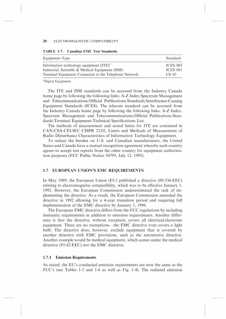
The ITE and ISM standards can be accessed from the Industry Canadahome page by following the following links: A-Z Index/Spectrum Managementand Telecommunications/Official Publications/Standards/Interference-CausingEquipment Standards (ICES). The telecom standard can be accessed fromthe Industry Canada home page by following the following links: A-Z Index/Spectrum Management and Telecommunications/Official Publications/Stan-dards/Terminal Equipment-Technical Specifications List.
The methods of measurement and actual limits for ITE are contained inCAN/CSA-CEI/IEC CISPR 22:02, Limits and Methods of Measurement ofRadio Disturbance Characteristics of Information Technology Equipment.
To reduce the burden on U.S. and Canadian manufacturers, the UnitedStates and Canada have a mutual recognition agreement whereby each countryagrees to accept test reports from the other country for equipment authoriza-tion purposes (FCC Public Notice 54795, July 12, 1995).
1.7 EUROPEAN UNION’S EMC REQUIREMENTS
In May 1989, the European Union (EU) published a directive (89/336/EEC)relating to electromagnetic compatibility, which was to be effective January 1,1992. However, the European Commission underestimated the task of im-plementing the directive. As a result, the European Commission amended thedirective in 1992 allowing for a 4-year transition period and requiring fullimplementation of the EMC directive by January 1, 1996.
The European EMC directive differs from the FCC regulations by includingimmunity requirements in addition to emission requirements. Another differ-ence is that the directive, without exception, covers all electrical/electronicequipment. There are no exemptions—the EMC directive even covers a lightbulb. The directive does, however, exclude equipment that is covered byanother directive with EMC provisions, such as the automotive directive.Another example would be medical equipment, which comes under the medicaldirective (93/42/EEC) not the EMC directive.
1.7.1 Emission Requirements
As stated, the EU’s conducted emission requirements are now the same as theFCC’s (see Tables 1-5 and 1-6 as well as Fig. 1-4). The radiated emission
TABLE 1-7. Canadian EMC Test Standards.
Equipment Type Standard
Information technology equipment (ITE)a ICES–003
Industrial, Scientific & Medical Equipment (ISM) ICES–001
Terminal Equipment Connected to the Telephone Network CS–03
aDigital Equipment.
20 ELECTROMAGNETIC COMPATIBILITY

standards are similar but not exactly the same. Table 1-8 shows the EuropeanUnion’s Class A and Class B radiated emission limits when measured at 10 m.
Figure 1-5 compares the EU’s radiated emission standard with the currentFCC standard over the frequency range of 30 MHz to 1000 MHz. The FCCClass B limits have been extrapolated to a 10-m measuring distance for thiscomparison. As can be observed the European (CISPR) limits are morerestrictive in the frequency range from 88 to 230 MHz. Below 88 MHz andabove 230 MHz the CISPR and FCC limits are virtually the same (within 0.5dB of each other). However, the EU has no radiated emission limit above 1GHz, whereas the FCC limits, under some circumstances (see Table 1-4), go upto 40 GHz.
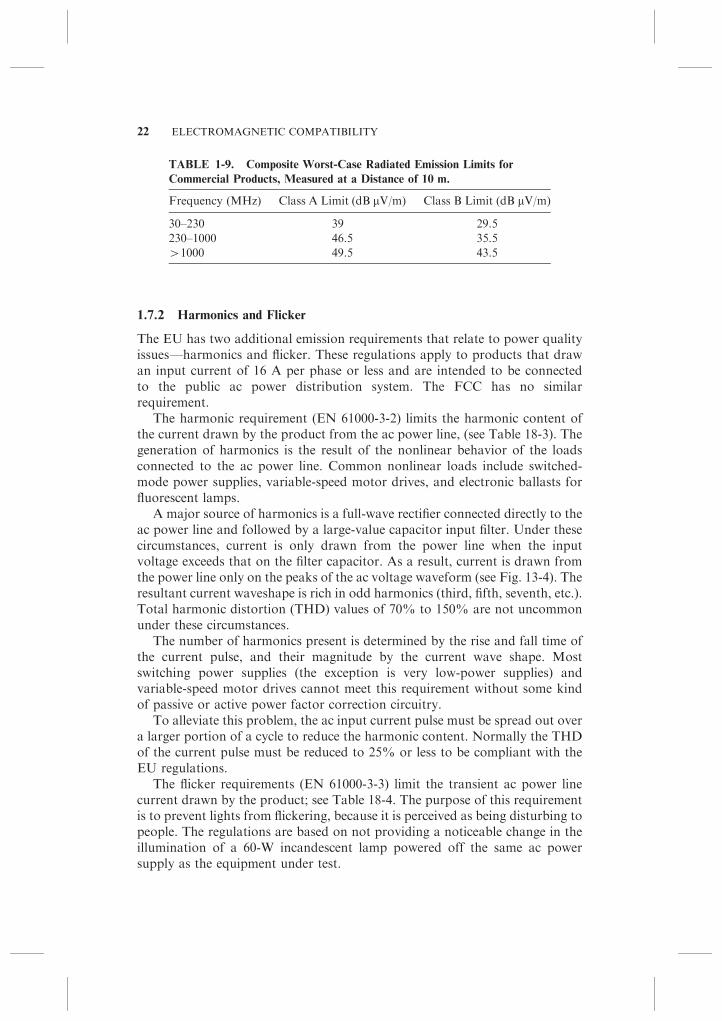
Table 1-9 is a composite worst-case combination of the FCC and CISPRradiated emission limits when measured at 10 m.
TABLE 1-8. CISPR Radiated Emission Limits at 10 m.
Frequency (MHz) Class A Limit (dB mV/m) Class B Limit (dB mV/m)
30–230 40 30
230–1000 47 37
70
60
50
40
30
20
10
FIE
LD S
TR
EN
GT
H (
dB µ
V/m
)
10 100
FREQUENCY (MHz)
1000
88 MHz
230 MHz
216 MHz
CISPR A
CISPR B
960 MHz
FCC A
FCC B
FIGURE 1-5. Comparison of FCC and CISPR radiated emission limits, measured at
a distance of 10 m.
1.7 EUROPEAN UNION’S EMC REQUIREMENTS 21
1.7.2 Harmonics and Flicker
The EU has two additional emission requirements that relate to power qualityissues—harmonics and flicker. These regulations apply to products that drawan input current of 16 A per phase or less and are intended to be connectedto the public ac power distribution system. The FCC has no similarrequirement.
The harmonic requirement (EN 61000-3-2) limits the harmonic content ofthe current drawn by the product from the ac power line, (see Table 18-3). Thegeneration of harmonics is the result of the nonlinear behavior of the loadsconnected to the ac power line. Common nonlinear loads include switched-mode power supplies, variable-speed motor drives, and electronic ballasts forfluorescent lamps.
A major source of harmonics is a full-wave rectifier connected directly to theac power line and followed by a large-value capacitor input filter. Under thesecircumstances, current is only drawn from the power line when the inputvoltage exceeds that on the filter capacitor. As a result, current is drawn fromthe power line only on the peaks of the ac voltage waveform (see Fig. 13-4). Theresultant current waveshape is rich in odd harmonics (third, fifth, seventh, etc.).Total harmonic distortion (THD) values of 70% to 150% are not uncommonunder these circumstances.
The number of harmonics present is determined by the rise and fall time ofthe current pulse, and their magnitude by the current wave shape. Mostswitching power supplies (the exception is very low-power supplies) andvariable-speed motor drives cannot meet this requirement without some kindof passive or active power factor correction circuitry.
To alleviate this problem, the ac input current pulse must be spread out overa larger portion of a cycle to reduce the harmonic content. Normally the THDof the current pulse must be reduced to 25% or less to be compliant with theEU regulations.
The flicker requirements (EN 61000-3-3) limit the transient ac power linecurrent drawn by the product; see Table 18-4. The purpose of this requirementis to prevent lights from flickering, because it is perceived as being disturbing topeople. The regulations are based on not providing a noticeable change in theillumination of a 60-W incandescent lamp powered off the same ac powersupply as the equipment under test.
TABLE 1-9. Composite Worst-Case Radiated Emission Limits for
Commercial Products, Measured at a Distance of 10 m.
Frequency (MHz) Class A Limit (dB mV/m) Class B Limit (dB mV/m)
30–230 39 29.5
230–1000 46.5 35.5
W1000 49.5 43.5
22 ELECTROMAGNETIC COMPATIBILITY
Because of the finite source impedance of the power line, the changingcurrent requirements of equipment connected to the line produces correspond-ing voltage fluctuations on the ac power line. If the voltage variation is largeenough, it will produce a perceptible change in lighting illumination. If the loadchanges are of sufficient magnitude and repetition rate, the resulting flickeringof lights can be irritating and disturbing.
To determine an applicable limit, many people were subjected to light flickerto determine the irritability threshold. When the flicker rate is low (o1 perminute), the threshold of irritability is when the ac line voltage changes by 3%.People are most sensitive to light flicker when the rate is around 1000 times perminute. At a rate of 1000 times per minute, a 0.3% voltage change is just asirritating as a 3% change at less than one change per minute. Above about 1800changes per minute, light flicker is no longer perceived.
Most EMC emission requirements are based on the magnitude of ameasured parameter not exceeding a specified amount (the limit). However,flicker tests are different in that they require many measurements to be madeand then a statistical analysis to be performed on the measured data todetermine whether the limit is exceeded.
For most equipment, this requirement is not a problem because theynaturally do not draw large transient currents off the ac power line. However,the requirement can be a problem for products that suddenly switch on heatersthat draw large currents, or motors under a heavy load. An example would bewhen an air conditioner compressor or a large heater in a copy machine issuddenly switched on.
1.7.3 Immunity Requirements
The EU’s immunity requirements cover radiated and conducted immunity, aswell as transient immunity that include ESD, electrical fast transient (EFT),and surge.
The EFT requirement simulates noise generated by inductively switchedloads on the ac power line. As a contactor is opened to an inductive load, an arcis formed that extinguishes and restarts many times. The surge requirement isintended to simulate the effect of a nearby lightning pulse.
In addition, the EU has susceptibility requirements that cover ac voltagedips, sags, and interruptions.
For additional information on these transient immunity and power linedisturbance requirements, see Sections 14.3 and 14.4.
1.7.4 Directives and Standards
The European regulations consist of directives and standards. The directivesare very general and are the legal requirements. The standards provide one way,but not the only way, to comply with the directive.
1.7 EUROPEAN UNION’S EMC REQUIREMENTS 23
The EMC Directive 2004/108/EC (which superceded the original EMCDirective 89/336/EEC) defines the essential requirements for a product to bemarketed in the EU. They are as follows:
1. The equipment must be constructed to ensure that any electromagneticdisturbance it generates allows radio and telecommunication equipmentand other apparatus to function as intended.
2. The equipment must be constructed with an inherent level of immunity toexternally generated electromagnetic disturbances.
These are the only legal requirements with respect to EMC and the require-ments are vague. The directive provides for two methods of demonstratingcompliance with its requirements. The most commonly used is by a declarationof conformity; the other option is the use of a technical construction file.
If a product is tested to and complies with the applicable EMC standards it ispresumed to meet the requirements of the directive, and the manufacturer canproduce a declaration of conformity attesting to that fact.
A declaration of conformity is a self-certification process in which theresponsible party, manufacturer or importer, must first determine the applic-able standards for the product, test the product to the standards, and issue adeclaration declaring compliance with those standards and the EMC directive.The declaration of conformity can be a single-page document but must containthe following:
� Application of which council directives (all applicable directives)
� Standards used (including date of standard) to determine conformity
� Product name and model number, also serial numbers if applicable
� Manufacturer’s name and address
� A dated declaration that the product conforms to the directives
� A signature by a person empowered to legally bind the manufacturer
The technical construction file approach to demonstrating conformity isunique to the European Union. The technical construction file is often usedwhere no harmonized standards exist for the product and the manufacturerdoes not think that the generic standards are appropriate. In this case, themanufacturer produces a technical file to describe the procedures and tests usedto ensure compliance with the EMC directive. The manufacturer can developits own EMC specifications and test procedures. The manufacturer can decidehow, where, when, or if, the product is tested for EMC. An independentcompetent body, however, must approve the technical construction file. Thecompetent bodies are appointed by the individual states of the EuropeanUnion, and the European Commission publishes a list of them in the OfficialJournal of the European Union. The competent body must agree that, using themanufacturer’s procedures and tests, the product satisfies the essential
24 ELECTROMAGNETIC COMPATIBILITY

requirements of the EMC directive. This approach is acceptable, because in theEuropean Union, the EMC directive is the legal document that must besatisfied, not the standards. In most other jurisdictions, the standards are thelegal documents that must be complied with.
Products whose compliance with the EMC directive has been demonstratedby one of the above procedures shall be labeled with the CE mark. The CEmark consists of the lower case letters ‘‘ce’’ in a specified, distinctive font.Affixing the CE mark to a product indicates conformity to all applicabledirectives, not just the EMC directive. Other applicable directives might be, thesafety directive, the toy directive, the machinery directive, and so on.
Two types of standards exist in the European Union: product specific andgeneric.* Product-specific standards always take precedence over genericstandards. However, if no applicable product-specific standard exists for aproduct, the generic standards are then applicable. Emission and immunityrequirements for a product are usually covered by different standards.Currently, over 50 different standards are associated with the EMC directive.Table 1-10 lists some of the more commonly applicable product-specificstandards, as well as the four generic EMC standards. If a product-specificstandard does not exist in a category, then the requirement defaults to theappropriate generic standard.
The EU’s standards writing organization CENELEC (the European Com-mittee for Electro-Technical Standardization) has been given the task ofdrawing up the corresponding technical specifications meeting the essentialrequirements of the EMC directive, compliance with which will provide apresumption of conformity with the essential requirements of the EMC
TABLE 1-10. European Union’s EMC Test Standards.
Equipment Type Emission Immunity
Product Specific Standards
Information Technology Equipment (ITE) EN 55022 EN 55024
Industrial, Scientific & Medical Equipment (ISM) EN 55011 –
Radio & Television Receivers EN 55013 EN 55020
Household Appliances/Electric Tools EN 55014-1 EN 55014-2
Lamps & Luminaries EN 55015 EN 61547
Adjustable Speed Motor Drives EN 61800-3 EN 61800-3
Medical Equipmenta EN 60601-1-2 EN 60601-1-2
Generic Standards
Residential, Commercial, Light Industrial Environment EN 61000-6-3 EN 61000-6-1
Heavy Industrial Environment EN 61000-6-4 EN 61000-6-2aCovered by the Medical Directive (93/42/EEC), not the EMC Directive
*A third type of standard also exists, which is a basic standard. Basic standards are usually test or
measurement procedures and are referenced by the product-specific or generic standards.
1.7 EUROPEAN UNION’S EMC REQUIREMENTS 25

directive. Such specifications are referred to as harmonized standards. MostCENELEC standards are derived from International Electro-Technical Com-mittee (ITC) or CISPR standards—ITC for immunity standards and CISPRfor emission standards. The CENELEC standards, or European Norms (EN),are not official until a reference to them is published in the ‘‘Official Journal ofthe European Union.’’
As new standards come into existence and existing standards are modified,as regularly happens, a transition period, usually of 2 years is specified inthe standard. During the transition period, either the old standard or the newstandard can be used to demonstrate compliance with the EMC directive.
The latest information on the EMC Directive 2004/108/EC and the harmo-nized standards can be obtained on the following website: http://europa.eu.int/comm/enterprise/newapproach/standardization/harmstds/reflist/emc.html.
In light of the large breadth and scope of the EMC Directive and the varietyof products covered, the European Commission in 1997 felt it necessary topublish a 124-page guideline to the interpretation of the EMC directive to beused by manufacturers, test laboratories, and other parties affected by thedirective (European Commission, 1997). This guideline was intended to clarifymatters and procedures relating to the interpretation of the EMC Directive. Italso clarified the application of the Directive to components, subassemblies,apparatus, systems, and installations, as well as the application of the Directiveto spare parts, used, and repaired apparatus.
1.8 INTERNATIONAL HARMONIZATION
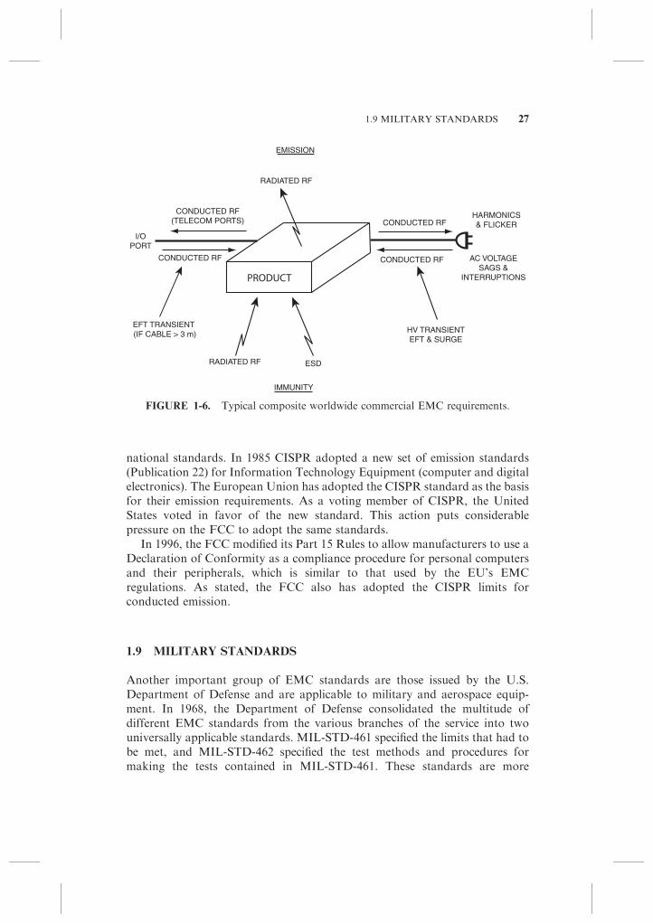
It would be desirable to have one international EMC standard for allowableemission and immunity of electronic products, instead of many differentnational standards. This would allow a manufacturer to design and test aproduct to one standard that would be acceptable worldwide. Figure 1-6depicts a typical commercial product and shows the different types of EMCrequirements, both emission and immunity, that it might have to meet in aharmonized world market.
Even more important than a single uniform EMC standard is a singleuniform EMC test procedure. If the test procedure is the same, then an EMCtest could be performed once and the results compared against many differentstandards (limits) to determine compliance with each regulation. When the testprocedures are different, however, the product must be retested for eachstandard, which is a costly and time-consuming task.
The most likely vehicle for accomplishing harmonization is the EuropeanUnion’s EMC standards, which are based on the CISPR standards. CISPR wasformed in 1934 to determine measurement methods and limits for radio-frequency interference to facilitate international trade. CISPR has no regula-tory authority, but its standards, when adopted by governments, become
26 ELECTROMAGNETIC COMPATIBILITY
national standards. In 1985 CISPR adopted a new set of emission standards(Publication 22) for Information Technology Equipment (computer and digitalelectronics). The European Union has adopted the CISPR standard as the basisfor their emission requirements. As a voting member of CISPR, the UnitedStates voted in favor of the new standard. This action puts considerablepressure on the FCC to adopt the same standards.
In 1996, the FCC modified its Part 15 Rules to allow manufacturers to use aDeclaration of Conformity as a compliance procedure for personal computersand their peripherals, which is similar to that used by the EU’s EMCregulations. As stated, the FCC also has adopted the CISPR limits forconducted emission.
1.9 MILITARY STANDARDS
Another important group of EMC standards are those issued by the U.S.Department of Defense and are applicable to military and aerospace equip-ment. In 1968, the Department of Defense consolidated the multitude ofdifferent EMC standards from the various branches of the service into twouniversally applicable standards. MIL-STD-461 specified the limits that had tobe met, and MIL-STD-462 specified the test methods and procedures formaking the tests contained in MIL-STD-461. These standards are more
PRODUCT
EMISSION
IMMUNITY
HARMONICS& FLICKERCONDUCTED RF
RADIATED RF
I/OPORT
CONDUCTED RF
RADIATED RF ESD
HV TRANSIENTEFT & SURGE
CONDUCTED RF(TELECOM PORTS)
CONDUCTED RF AC VOLTAGESAGS &
INTERRUPTIONS
EFT TRANSIENT (IF CABLE > 3 m)
FIGURE 1-6. Typical composite worldwide commercial EMC requirements.
1.9 MILITARY STANDARDS 27

stringent than the FCC regulations, and they cover immunity as well asemissions in the frequency range of 30 Hz to 40 GHz.
Over the years, these standards have gone through revisions that rangedfrom MIL-STD-461A in 1968 to MIL-STD-461E in 1999. In 1999, MIL-STD-461D (Limits) and MIL-STD-462D (Test Procedures) were merged into onestandard MIL-STD-461E that covered both limits and test procedures.*
Unlike commercial standards, MIL-STDs are not legal requirements; rather,they are contractual requirements. As such, test limits can be negotiated andwaivers are possible. Earlier versions are still applicable to current productsbecause the requirements are contractual, not legal. Normally whatever versionthe original procurement contract specified is still applicable.w
The test procedures specified in the military standards are often differentthan those specified by commercial EMC standards, which makes a directcomparison of the limits difficult. For radiated emissions the military standardspecifies enclosed chamber (shielded room) testing, whereas the FCC and theEU rules require open-area testing. For conducted emission testing, the militarystandards originally measured current, whereas the commercial standardsmeasure voltage.
As more was learned about EMC testing and its accuracy, the military hascome under some criticism for some of its test procedures. As a result, themilitary has adopted some of the commercial test procedures. For example,MIL-STD-461E specifies the use of a LISN and the measurement of voltagerather than current for conducted emission testing. Also MIL-STD-461Erequires that some absorber material must be used on the walls of chambersused for emission and immunity testing to make the chamber at least partiallyanechoic.
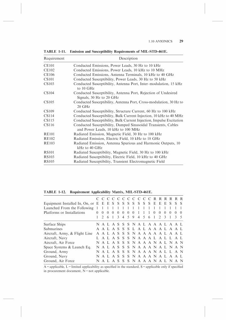
Table 1-11 is a list of the emission and immunity requirements established byMIL-STD-461E. Tests are required for both radiated and conducted emissionsas well as for radiated, conducted, and high-voltage transient susceptibility.
The military standards are application specific, often with different limits fordifferent environments (such as Army, Navy, aerospace, etc.). Some require-ments listed in Table 1-11 are applicable to only certain environments and notto others. Table 1-12 lists the applicability of the requirements to the variousenvironments.
1.10 AVIONICS
The commercial avionics industry has its own set of EMC standards, which aresimilar to those of the military. These standards apply to the entire spectrum ofcommercial aircraft, which includes light general aviation aircraft, helicopters,
*On December 10, 2007, MIL-STD 461F was released.wBy contrast, when a commercial standard is revised or modified, all newly manufactured products
must comply with the new limits by the end of the specified transition period.
28 ELECTROMAGNETIC COMPATIBILITY
1.10 AVIONICS 29
TABLE 1-11. Emission and Susceptibility Requirements of MIL-STD-461E.
Requirement Description
CE101 Conducted Emissions, Power Leads, 30 Hz to 10 kHz
CE102 Conducted Emissions, Power Leads, 10 kHz to 10 MHz
CE106 Conducted Emissions, Antenna Terminals, 10 kHz to 40 GHz
CS101 Conducted Susceptibility, Power Leads, 30 Hz to 50 kHz
CS103 Conducted Susceptibility, Antenna Port, Inter–modulation, 15 kHz
to 10 GHz
CS104 Conducted Susceptibility, Antenna Port, Rejection of Undesired
Signals, 30 Hz to 20 GHz
CS105 Conducted Susceptibility, Antenna Port, Cross-modulation, 30 Hz to
20 GHz
CS109 Conducted Susceptibility, Structure Current, 60 Hz to 100 kHz
CS114 Conducted Susceptibility, Bulk Current Injection, 10 kHz to 40 MHz
CS115 Conducted Susceptibility, Bulk Current Injection, Impulse Excitation
CS116 Conducted Susceptibility, Damped Sinusoidal Transients, Cables
and Power Leads, 10 kHz to 100 MHz
RE101 Radiated Emission, Magnetic Field, 30 Hz to 100 kHz
RE102 Radiated Emission, Electric Field, 10 kHz to 18 GHz
RE103 Radiated Emission, Antenna Spurious and Harmonic Outputs, 10
kHz to 40 GHz
RS101 Radiated Susceptibility, Magnetic Field, 30 Hz to 100 kHz
RS103 Radiated Susceptibility, Electric Field, 10 kHz to 40 GHz
RS105 Radiated Susceptibility, Transient Electromagnetic Field
TABLE 1-12. Requirement Applicability Matrix, MIL-STD-461E.
C C C C C C C C C C C R R R R R R
Equipment Installed In, On, or E E E S S S S S S S S E E E S S S
Launched From the Following 1 1 1 1 1 1 1 1 1 1 1 1 1 1 1 1 1
Platforms or Installations 0 0 0 0 0 0 0 0 1 1 1 0 0 0 0 0 0
1 2 6 1 3 4 5 9 4 5 6 1 2 3 1 3 5
Surface Ships N A L A S S S N A L A A A L A A L
Submarines A A L A S S S L A L A A A L A A L
Aircraft, Army, & Flight Line A A L A S S S N A A A A A L A A L
Aircraft, Navy L A L A S S S N A A A L A L L A L
Aircraft, Air Force N A L A S S S N A A A N A L N A N
Space Systems & Launch Eq. N A L A S S S N A A A N A L N A N
Ground, Army N A L A S S S N A A A N A L L A N
Ground, Navy N A L A S S S N A A A N A L A A L
Ground, Air Force N A L A S S S N A A A N A L N A N
A=applicable, L=limited applicability as specified in the standard, S=applicable only if specified
in procurement document, N=not applicable.

and jumbo jets. The Radio Technical Commission for Aeronautics (RTCA)produces these standards for the avionics industry. The current version isRTCA/DO-160E Environmental Conditions and Test Procedures For AirborneEquipment and was issued in December 2004. Sections 15 through 23 andSection 25 cover EMC issues.
Like the military standard, DO-160E is a contractual, not legal, requirement,so its terms may be negotiable.
1.11 THE REGULATORY PROCESS
We are all probably familiar with the phrase ignorance of the law is no defense.How then do governments make their commercial EMC regulations public, sothat we all presumably know of their existence? In most countries, regulationsare made public by publication, or being referenced, in the ‘‘Official Journal’’ ofthat country. In the United States, the official journal is the Federal Register; inCanada, it is the Canada Gazette; and in the European Union, it is the OfficialJournal of the European Union.
Once a regulation is published, or referenced, in the official journal, itsofficial, and everyone is presumed to know of its existence.
1.12 TYPICAL NOISE PATH
A block diagram of a typical noise path is shown in Fig. 1-7. As shown, threeelements are necessary to produce an interference problem. First, there must be anoise source. Second, there must be a receptor circuit that is susceptible to thenoise. Third, there must be a coupling channel to transmit the noise from the sourceto the receptor. In addition, the characteristics of the noise must be such that it isemitted at a frequency that the receptor is susceptible, an amplitude sufficient toaffect the receptor, and a time the receptor is susceptible to the noise. A good wayto remember the important noise characteristics is with the acronym FAT.
The first step in analyzing a noise problem is to define the problem. This isdone by determining what is the noise source, what is the receptor, what isthe coupling channel, and what are the FAT characteristics of the noise. Itfollows that there are three ways to break the noise path: (1) the characteristicsof the noise can be changed at the source, (2) the receptor can be madeinsensitive to the noise, or (3) the transmission through the coupling channel
FIGURE 1-7. Before noise can be a problem, there must be a noise source, a receptor,
and a coupling channel.
30 ELECTROMAGNETIC COMPATIBILITY
can be eliminated or minimized. In some cases, the noise suppression techni-ques must be applied to two or to all three parts of the noise path.
In the case of an emission problem, we are most likely to attack the source ofthe emissions by changing its characteristics—its frequency, amplitude, or time.For a susceptibility problem, we are most likely to direct our attention tomodifying the receptor to increase its immunity to the noise. In many cases,modifying the source or receptor is not practical, which then leaves us with onlythe option of controlling the coupling channel.
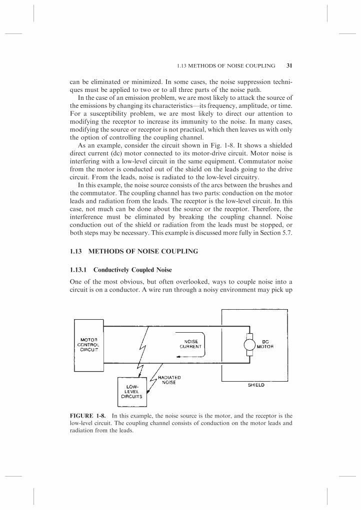
As an example, consider the circuit shown in Fig. 1-8. It shows a shieldeddirect current (dc) motor connected to its motor-drive circuit. Motor noise isinterfering with a low-level circuit in the same equipment. Commutator noisefrom the motor is conducted out of the shield on the leads going to the drivecircuit. From the leads, noise is radiated to the low-level circuitry.
In this example, the noise source consists of the arcs between the brushes andthe commutator. The coupling channel has two parts: conduction on the motorleads and radiation from the leads. The receptor is the low-level circuit. In thiscase, not much can be done about the source or the receptor. Therefore, theinterference must be eliminated by breaking the coupling channel. Noiseconduction out of the shield or radiation from the leads must be stopped, orboth steps may be necessary. This example is discussed more fully in Section 5.7.
1.13 METHODS OF NOISE COUPLING
1.13.1 Conductively Coupled Noise
One of the most obvious, but often overlooked, ways to couple noise into acircuit is on a conductor. A wire run through a noisy environment may pick up
FIGURE 1-8. In this example, the noise source is the motor, and the receptor is the
low-level circuit. The coupling channel consists of conduction on the motor leads and
radiation from the leads.
1.13 METHODS OF NOISE COUPLING 31
noise and then conduct it to another circuit. There it causes interference. Thesolution is to prevent the wire from picking up the noise or to remove the noisefrom it by filtering before it interferes with the susceptible circuit.
The major example in this category is noise conducted into a circuit on thepower supply leads. If the designer of the circuit has no control over the powersupply, or if other equipment is connected to the power supply, it becomesnecessary to decouple or filter the noise from the wires before they enter thecircuit. A second example is noise coupled into or out of a shielded enclosure bythe wires that pass through the shield.
1.13.2 Common Impedance Coupling
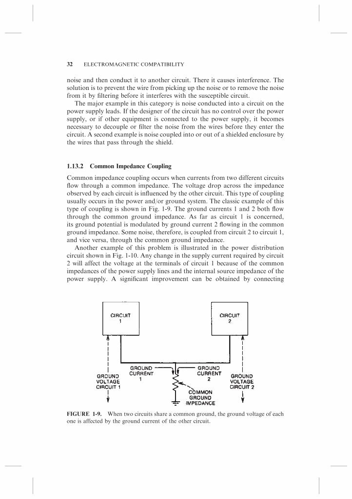
Common impedance coupling occurs when currents from two different circuitsflow through a common impedance. The voltage drop across the impedanceobserved by each circuit is influenced by the other circuit. This type of couplingusually occurs in the power and/or ground system. The classic example of thistype of coupling is shown in Fig. 1-9. The ground currents 1 and 2 both flowthrough the common ground impedance. As far as circuit 1 is concerned,its ground potential is modulated by ground current 2 flowing in the commonground impedance. Some noise, therefore, is coupled from circuit 2 to circuit 1,and vice versa, through the common ground impedance.
Another example of this problem is illustrated in the power distributioncircuit shown in Fig. 1-10. Any change in the supply current required by circuit2 will affect the voltage at the terminals of circuit 1 because of the commonimpedances of the power supply lines and the internal source impedance of thepower supply. A significant improvement can be obtained by connecting
FIGURE 1-9. When two circuits share a common ground, the ground voltage of each
one is affected by the ground current of the other circuit.
32 ELECTROMAGNETIC COMPATIBILITY
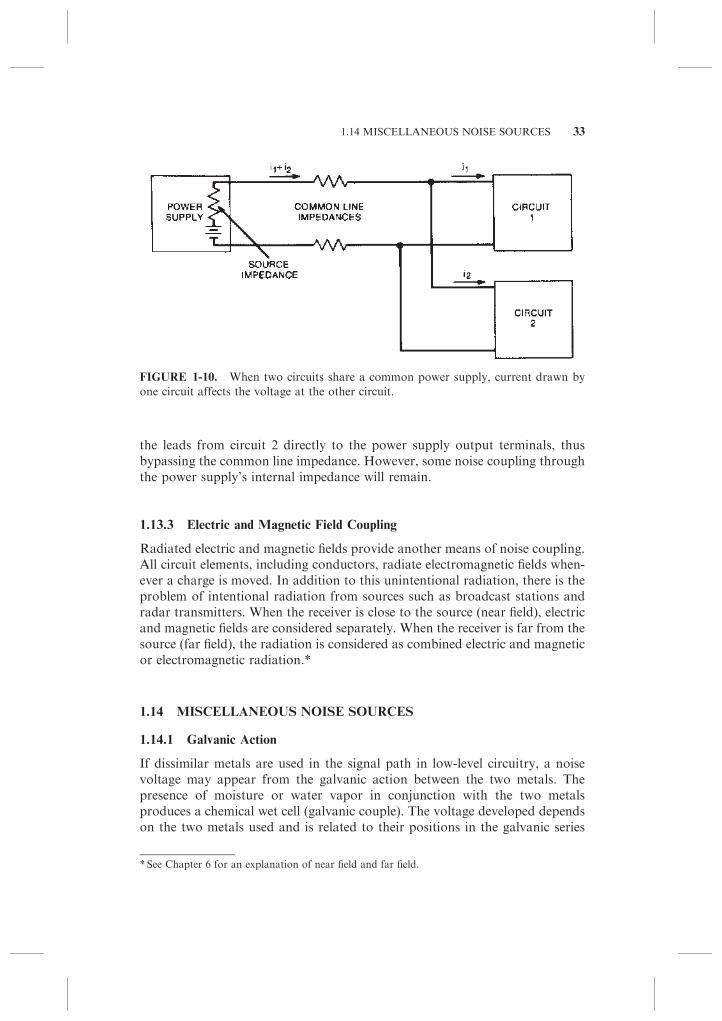
the leads from circuit 2 directly to the power supply output terminals, thusbypassing the common line impedance. However, some noise coupling throughthe power supply’s internal impedance will remain.
1.13.3 Electric and Magnetic Field Coupling
Radiated electric and magnetic fields provide another means of noise coupling.All circuit elements, including conductors, radiate electromagnetic fields when-ever a charge is moved. In addition to this unintentional radiation, there is theproblem of intentional radiation from sources such as broadcast stations andradar transmitters. When the receiver is close to the source (near field), electricand magnetic fields are considered separately. When the receiver is far from thesource (far field), the radiation is considered as combined electric and magneticor electromagnetic radiation.*
1.14 MISCELLANEOUS NOISE SOURCES
1.14.1 Galvanic Action
If dissimilar metals are used in the signal path in low-level circuitry, a noisevoltage may appear from the galvanic action between the two metals. Thepresence of moisture or water vapor in conjunction with the two metalsproduces a chemical wet cell (galvanic couple). The voltage developed dependson the two metals used and is related to their positions in the galvanic series
FIGURE 1-10. When two circuits share a common power supply, current drawn by
one circuit affects the voltage at the other circuit.
* See Chapter 6 for an explanation of near field and far field.
1.14 MISCELLANEOUS NOISE SOURCES 33

shown in Table 1-13. The farther apart the metals are on this table, the largerthe developed voltage. If the metals are the same, no potential difference candevelop.
In addition to producing a noise voltage, the use of dissimilar metals canproduce a corrosion problem. Galvanic corrosion causes positive ions fromone metal to be transferred to the other one. This action gradually causesthe anode material to be destroyed. The rate of corrosion depends on themoisture content of the environment and how far apart the metals are inthe galvanic series. The farther apart the metals are in the galvanic series, thefaster the ion transfer. An undesirable, but common, combination of metals isaluminum and copper. With this combination, the aluminum is eventuallyeaten away. The reaction slows down considerably, however, if the copper iscoated with lead-tin solder because aluminum and lead-tin solder are closer inthe galvanic series.
The following four elements are needed before galvanic action can occur:
1. Anode material (higher rank in Table 1-13)
2. Electrolyte (usually present as moisture)
3. Cathode material (lower rank in Table 1-13)
4. Conducting electrical connection between anode and cathode (usuallypresent as a leakage path)
TABLE 1-13. Galvanic Series.
ANODIC END
(Most susceptible to corrosion)
Group I 1. Magnesium 13. Nickel (active)
14. Brass
2. Zinc 15. Copper
3. Galvanized steel 16. Bronze
Group II 4. Aluminum 2S Group IV 17. Copper-nickel alloy
5. Cadmium 18. Monel
6. Aluminum 17ST 19. Silver solder
20. Nickel (passive)a
7. Steel 21. Stainless steel
8. Iron (passive)a
9. Stainless steel
Group III (active) 22. Silver
10. Lead-tin solder Group V 23. Graphite
11. Lead 24. Gold
12. Tin 25 Platinum
CATHODIC END
(Least susceptibility to corrosion)
aPassivation by immersion in a strongly acidic solution.
34 ELECTROMAGNETIC COMPATIBILITY
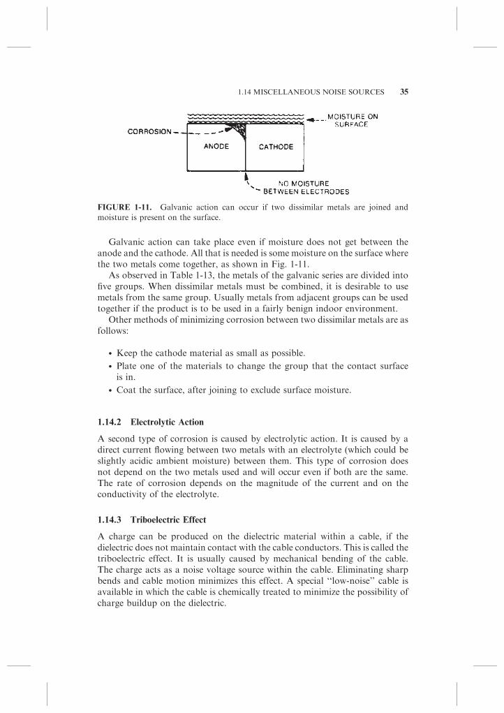
Galvanic action can take place even if moisture does not get between theanode and the cathode. All that is needed is some moisture on the surface wherethe two metals come together, as shown in Fig. 1-11.
As observed in Table 1-13, the metals of the galvanic series are divided intofive groups. When dissimilar metals must be combined, it is desirable to usemetals from the same group. Usually metals from adjacent groups can be usedtogether if the product is to be used in a fairly benign indoor environment.
Other methods of minimizing corrosion between two dissimilar metals are asfollows:
� Keep the cathode material as small as possible.
� Plate one of the materials to change the group that the contact surfaceis in.
� Coat the surface, after joining to exclude surface moisture.
1.14.2 Electrolytic Action
A second type of corrosion is caused by electrolytic action. It is caused by adirect current flowing between two metals with an electrolyte (which could beslightly acidic ambient moisture) between them. This type of corrosion doesnot depend on the two metals used and will occur even if both are the same.The rate of corrosion depends on the magnitude of the current and on theconductivity of the electrolyte.
1.14.3 Triboelectric Effect
A charge can be produced on the dielectric material within a cable, if thedielectric does not maintain contact with the cable conductors. This is called thetriboelectric effect. It is usually caused by mechanical bending of the cable.The charge acts as a noise voltage source within the cable. Eliminating sharpbends and cable motion minimizes this effect. A special ‘‘low-noise’’ cable isavailable in which the cable is chemically treated to minimize the possibility ofcharge buildup on the dielectric.
FIGURE 1-11. Galvanic action can occur if two dissimilar metals are joined and
moisture is present on the surface.
1.14 MISCELLANEOUS NOISE SOURCES 35
1.14.4 Conductor Motion
If a conductor is moved through a magnetic field, a voltage is induced betweenthe ends of the wire. Because of power wiring and other circuits with high-current flow, stray magnetic fields exist in most environments. If a wire with alow-level signal is allowed to move through this field, then a noise voltage willbe induced in the wire. This problem can be especially troublesome in avibrational environment. The solution is simple: prevent wire motion with cableclamps and other tie-down devices.
1.15 USE OF NETWORK THEORY
For the exact answer to the question of how any electric circuit behaves,Maxwell’s equations must be solved. These equations are functions of threespace variables (x, y, z) and of time (t)—a four-dimensional problem. Solutionsfor any but the simplest problems are usually complex. To avoid this complex-ity, an approximate analysis technique called ‘‘electric circuit analysis’’ is usedduring most design procedures.
Circuit analysis eliminates the spatial variables and provides approximatesolutions as a function of time (or frequency) only. Circuit analysis assumes thefollowing:
1. All electric fields are confined to the interiors of capacitors.
2. All magnetic fields are confined to the interiors of inductors.
3. Dimensions of the circuits are small compared with the wavelength(s)under consideration.
What is really implied is that external fields, even though actually present,can be neglected in the solution of the network. Yet these external fieldsmay not necessarily be neglected where their effect on other circuits isconcerned.
For example, a 100-W power amplifier may radiate 100mW of power. These100 mW are completely negligible as far as the analysis and operation of thepower amplifier is concerned. However, if only a small percentage of thisradiated power is picked up on the input of a sensitive circuit, it may causeinterference.
Even though the 100mW of radiated emission is completely negligible to the100-W power amplifier, a sensitive radio receiver, under the right conditions,may be capable of picking up the signal thousands of miles away.
Whenever possible, noise-coupling channels are represented as equivalentlumped component networks. For instance, a time-varying electric field thatexists between two conductors can be represented by a capacitor connecting thetwo conductors as shown in Fig. 1-12. A time-varying magnetic field that
36 ELECTROMAGNETIC COMPATIBILITY

couples two conductors can be represented by a mutual inductance between thetwo circuits as shown in Fig. 1-13.
For this approach to be valid, the physical dimensions of the circuits must besmall compared with the wavelengths of the signals involved. Whereverappropriate, this assumption is made throughout this book.
Even when this assumption is not truly valid, the lumped componentrepresentation is still useful for the following reasons:
1. The solution of Maxwell’s equations is not practical for most ‘‘real-world’’ noise problems because of the complicated boundary conditions.
2. Although lumped component representation will not produce the mostaccurate numerical answer, it does clearly show how noise depends onthe parameters of the system. On the other hand, the solution ofMaxwell’s equations, even if possible, does not clearly show suchparameter dependence.
3. To solve a noise problem, a parameter of the system must be changed,and lumped circuit analysis clearly points out the parameter dependence.
In general, the numerical values of the lumped components are extremelydifficult to calculate with any precision, except for certain special geometries.One can conclude, however, that these components exist, and as will be shown,the results can be very useful even when the components are only defined ina qualitative sense.
FIGURE 1-12. When two circuits are coupled by an electric field, the coupling can be
represented by a capacitor.
1.15 USE OF NETWORK THEORY 37
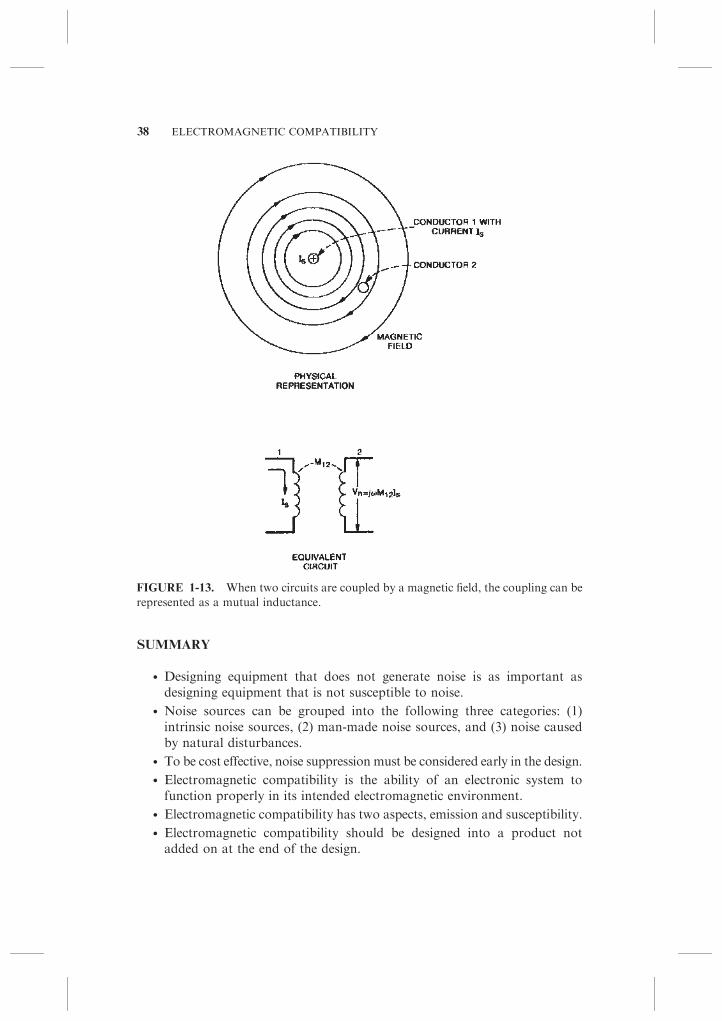
SUMMARY
� Designing equipment that does not generate noise is as important asdesigning equipment that is not susceptible to noise.
� Noise sources can be grouped into the following three categories: (1)intrinsic noise sources, (2) man-made noise sources, and (3) noise causedby natural disturbances.
� To be cost effective, noise suppression must be considered early in the design.
� Electromagnetic compatibility is the ability of an electronic system tofunction properly in its intended electromagnetic environment.
� Electromagnetic compatibility has two aspects, emission and susceptibility.
� Electromagnetic compatibility should be designed into a product notadded on at the end of the design.
FIGURE 1-13. When two circuits are coupled by a magnetic field, the coupling can be
represented as a mutual inductance.
38 ELECTROMAGNETIC COMPATIBILITY
� Most electronic equipment must comply with EMC regulations beforebeing marketed.
� EMC regulations are not static but are continually changing.
� The three major EMC regulations are the FCC rules, the EuropeanUnion’s regulations, and the military standards.
� The following products are temporarily exempt from the FCC requirements:
� Digital electronics in transportation vehicles
� Industrial control systems
� Test equipment
� Home appliances
� Specialized medical devices
� Devices with power consumption not exceeding 6 nW
� Joystick controllers or similar devices
� Devices with clock frequencies less than 1.705 kHz, and which do notoperate from the AC power line
� Virtually no products are exempt from the European Union’s EMCrequirements.
� Electromagnetic compatibility should be a major design objective.
� The following three items are necessary to produce an interference problem:
� A noise source
� A coupling channel
� A susceptible receptor
� Three important characteristics of noise are as follows:
� Frequency
� Amplitude
� Time (when does it occur)
� Metals in contact with each other must be galvanically compatible.
� Noise can be reduced in an electronic system using many techniques; asingle unique solution to most noise reduction problems does not exist.
PROBLEMS
1.1 What is the difference between noise and interference?
1.2 a. Does a digital watch satisfy the FCC’s definition of a digital device?
b. Does a digital watch have to meet the FCC’s EMC requirements?
1.3 a. Does test equipment have to meet the technical standards of the FCC’sPart 15 EMC regulations?
b. Does test equipment have to meet the non-interference requirement ofthe FCC’s Part 15 EMC regulations?
PROBLEMS 39

1.4 a. Who is responsible for meeting the technical standards of the FCC’sEMC regulations?
b. Who is responsible for meeting the non-interference requirement of theFCC’s EMC regulations?
1.5 Are the FCC’s or the European Union’s Class B radiated emission limitsmore restrictive:
a. In the frequency range of 30 to 88 MHz?b. In the frequency range of 88 to 230 MHz?c. In the frequency range of 230 to 960 MHz?d. In the frequency range of 960 to 1000 MHz?
1.6 a. Over what frequency range, below 500 MHz, does the maximumdifference exist between the FCC’s and the European Union’s ClassB radiated emission limits?
b. What is the magnitude of the maximum difference over this frequencyrange?
1.7 a. Over what frequency range does the FCC specify conducted emissionlimits?
b. Over what frequency range does the FCC specify radiated emissionlimits?
1.8 a. What are the essential requirements for a product to be marketed in theEuropean Union?
b. Where are the essential requirements defined?
1.9 By what process are commercial EMC regulations made public?
1.10 What is the major difference between the FCC’s EMC requirement andthe European Union’s EMC requirements?
1.11 What additional emission requirements does the European Union havethat the FCC does not?
1.12 Your company is in the process of designing a new electronic widget to bemarketed in the European Union. The widget will be used in bothresidential and commercial environments. You review the most currentlist of harmonized product specific EMC standards, and none of themapply to widgets. What EMC standards (specifically) should you use todemonstrate EMC compliance?
1.13 To be legally marketed in the European Union, must an electronicproduct be compliant with the harmonized EMC standards?
1.14 In the European Union, what are the two methods of demonstratingcompliance with the EMC directive?
1.15 Which of the following EMC standards are legal requirements and whichare contractual?
� FCC Part 15 B
� MIL-STD-461E
40 ELECTROMAGNETIC COMPATIBILITY

� 2004/108/EC EMC Directive
� RTCA/DO-160E for avionics
� GR-1089 for telephone network equipment
� TIA-968 for telecom terminal equipment
� SAE J551 for automobiles
1.16 What are the official journals of the following countries: the UnitedStates, Canada, and the European Union?
1.17 In the United States, does medical equipment have to meet the FCC’sEMC requirements?
1.18 What are the three necessary elements to produce an interference problem?
1.19 When analyzing the characteristics of a noise source, what does theacronym FAT stand for?
1.20 a. Which of the following metals is the most susceptible to corrosion:cadmium, nickel (passive), magnesium, copper, or steel?
b. Which is the least susceptible to corrosion?
1.21 If a tin plate is bolted to a zinc casting, because of galvanic action, whichmetal will be corroded or eaten away?
REFERENCES
2004/108/EEC. Council Directive 2004/108/EEC Relating to Electromagnetic Compat-
ibility and Repealing Directive 89/336/EEC, Official Journal of the European Union,
No. L 390 December 31, 2004, pp. 24–37.
ANSI C63.4-1992.Methods of Measurement of Radio-Noise Emissions from Low-Voltage
Electrical and Electronic Equipment in the Range of 9 kHz to 40 GHz, IEEE, July 17,
1992.
CAN/CSA-CEI/IEC CISPR 22:02. Limits an Methods of Measurement of Radio
Disturbance Characteristics of Information Technology Equipment, Canadian Stan-
dards Association, 2002.
CISPR, Publication 22. ‘‘Limits and Methods of Measurement of Radio Interference
Characteristics of Information Technology Equipment,’’ 1997.
Code of Federal Regulations, Title 47, Telecommunications (47CFR). Parts 1, 2, 15, 18,
and 68, U.S. Government Printing Office, Washington, DC.
EMCAB-1, Issue 2. Electromagnetic Compatibility Bulletin, ‘‘Immunity of Electrical/
Electronic Equipment Intended to Operate in the Canadian Radio Environment
(0.014–10,000 MHz).’’ Government of Canada, Department of Communications,
August 1, 1982.
EN 61000-3-2. Electromagnetic Compatibility (EMC)—Part 3-2: Limits—Limits for
Harmonic Current Emissions (Equipment Input Current r 16 A Per Phase),
CENELEC, 2006.
EN 61000-3-3. Electromagnetic Compatibility (EMC)—Part 3-3: Limits—Limitation of
Voltage Changes, Voltage Fluctuations and Flicker in Public Low-Voltage Supply
REFERENCES 41
Systems, for Equipment with Rated Current r 16 A Per Phase and Not Subject to
Conditional Connection, CENELEC, 2006.
European Commission. Guidelines on the Application of Council Directive 89/336/EEC
on the Approximation of the Laws of the Member States Relating to Electromagnetic
Compatibility, European Commission, 1997.
FCC. ‘‘Commission Cautions Against Changes in Verified Computing Equipment.’’
Public Notice No. 3281, April 7, 1982.
FCC. ‘‘United States and Canada Agree on Acceptance of Measurement Reports for
Equipment Authorization,’’ Public Notice No. 54795, July 12, 1995.
FDA. Guide to Inspections of Electromagnetic Compatibility Aspects of Medical Device
Quality Systems, US Food and Drug Administration, Available at http://www.fda.
gov/ora/inspect_ref/igs/elec_med_dev/emc1.html. Accessed September 2008.
GR-1089-CORE. Electromagnetic Compatibility and Electrical Safety—Generic Criteria
for Network Telecommunications Equipment, Telcordia, November 2002.
Heirman, D. N. ‘‘Broadcast Electromagnetic Environment Near Telephone Equip-
ment.’’ IEEE National Telecommunications Conference, 1976.
Janes, D. E. et al. ‘‘Nonionizing Radiation Exposure in Urban Areas of the United
States.’’ Proceedings of the 5th International Radiation Protection Association. April
1977.
MDS-201-0004. Electromagnetic Compatibility Standards for Medical Devices, U.S.
Department of Health Education and Welfare, Food and Drug Administration,
October 1, 1979.
MIL-STD-461E. Requirements For The Control of Electromagnetic Interference Char-
acteristics of Subsystems and Equipment, August 20, 1999.
MIL-STD-889B. Dissimilar Metals, Notice 3, May 1993.
RTCA/DO-160E. Environmental Conditions and Test Procedures for Airborne Equip-
ment, Radio Technical Commission for Aeronautics (RTCA), December 7, 2004.
SAE J551. Performance Levels and Methods of Measurement of Electromagnetic
Compatibility of Vehicles and Devices (60 Hz to 18 GHz), Society of Automotive
Engineers, June 1996.
SAE J1113. Electromagnetic Compatibility Measurement Procedure for Vehicle Compo-
nents (Except Aircraft) (60 Hz to 18 GHz), Society of Automotive Engineers, July
1995.
TIA-968-A. Telecommunications Telephone Terminal Equipment Technical Requirements
for Connection of Terminal Equipment to the Telephone Network, Telecommunica-
tions Industry Association, October 1, 2002.
FURTHER READING
Cohen, T. J., and McCoy, L. G. ‘‘RFI–A New Look at an Old Problem.’’ QST, March
1975.
42 ELECTROMAGNETIC COMPATIBILITY

Gruber, M. ed. The ARRL RFI Book, Newington, CT, American Radio Relay League,
2007.
Marshman, C. The Guide to the EMC Directive 89/336/EEC, IEEE Press, New York,
1992.
Wall, A. ‘‘ Historical Perspective of the FCC Rules For Digital Devices and a Look to
the Future,’’ 2004 IEEE International Symposium on Electromagnetic Compatibility,
August 9–13, 2004.
FURTHER READING 43


![Crisis of Secularism and Loalty Towards the Dominant Group [EMC]](https://static.fdocuments.us/doc/165x107/55cf9a5d550346d033a165a9/crisis-of-secularism-and-loalty-towards-the-dominant-group-emc-5659d35ceb57c.jpg)