Part 61 Instrument Training Digest -...
40
Part 61 Instrument Training Digest Student Name: ____________________ Scott O’Brien, CFII & MEI 3551 Lakeshore Dr. Tallahassee, FL 32312 Phone: 850-386-4698 Mobile: 850-284-9310 E-Mail: [email protected] The essence of this Part 61 Instrument Training Digest is to enhance the ability to tailor a flight training program to fit the varying requirements of a particular student, training environment and training aircraft. Additionally it is recognized that flight instructors of Part 61 flight schools many times have differing teaching techniques and different approaches to various aviation subjects that work best for their style of instruction and training location. This Part 61 Instrument Training Digest is intended to be modified and supplemented to fit particular and different sets of needs in order to produce a satisfying student experience and a high student success rate.
Transcript of Part 61 Instrument Training Digest -...

Part 61 Instrument Training Digest
Student Name: ____________________
Scott O’Brien, CFII & MEI 3551 Lakeshore Dr. Tallahassee, FL 32312 Phone: 850-386-4698 Mobile: 850-284-9310 E-Mail: [email protected]
The essence of this Part 61 Instrument Training Digest is to enhance the ability to tailor a flight training program to fit the varying requirements of a particular student, training environment and training aircraft. Additionally it is recognized that flight instructors of Part 61 flight schools many times have differing teaching techniques and different approaches to various aviation subjects that work best for their style of instruction and training location. This Part 61 Instrument Training Digest is intended to be modified and supplemented to fit particular and different sets of needs in order to produce a satisfying student experience and a high student success rate.

Page 2 of 40
Instrument Training
Name: _________________________ Birth Date: _______________
Address: _________________________ Phone-H: _______________
_________________________ Phone-W: _______________
_________________________ Phone-M: _______________
E-Mail: ___________________________________________________ Grade of Certificate: ____________ Certificate #: ___________________
Class of Medical: ______________ Date of Medical: ____________
Total Flight Time: _______ Date Last Flight Review: __________
Total PIC X-Country Time: _______ Date Instrument Training Started: __________
Projected Date to Take Instrument Knowledge Test: _____________
Flight Training Number (FTN):_____________
Knowledge Test ID: ______________ Date passed: _______ Score: ____ Passport #_____________ Country_____________ or
Birth Certificate #________ Country_______ City/ST/County___________
I certify that [student's name] has presented a [insert type of document or documents presented, such as current US passport, including the identifying number on the document, if any] establishing US citizenship or nationality in accordance with 49 CFR 1552.3(h).
_____________________________________ __________________ CFII # _________________ Exp __________ Date

Page 3 of 40
Contents Curriculum ........................................................................................4 FAR 61.65 (d) Instrument Rating Aeronautical Experience ............5 Aircraft Power Sheet ........................................................................6 Check List / iPad / Panel-Mount GPS ..............................................7 Electronic Helpers ............................................................................8 IFR Re-Check ............................................................................... 10 GUMPS Checklist ......................................................................... 11 Heading Indicator Right Hold Hints ............................................... 12 Heading Indicator Left Hold Hints ................................................. 13 WAYPOINT Intercepts .................................................................. 14 Timed Turns & Weather Minimums .............................................. 15 Pattern A ....................................................................................... 16 Pattern B ....................................................................................... 17 Climb Gradient Table .................................................................... 18 WAAS Approaches ....................................................................... 19 Instrument Pilot Practical Test Review ......................................... 20 Sayings ......................................................................................... 21 Regulations ................................................................................... 22 IFR Compliance Entries ................................................................ 38 Weather ........................................................................................ 39 IFR Flight Planning ....................................................................... 40
Copyright © 1998 – 2013 Scott O’Brien, MCFI, Gold Seal, FAASTeam Tampa FSDO
The use, including the copying of the materials herein, by individual FAA Certified Flight Instructors is authorized and encouraged for use by such instructors in the training and education of their flight students. Any other commercial copying and/or distribution of these materials is strictly prohibited. To facilitate use in the cockpit, this Digest is intended to be spiral bound at the top and printed on 4 ¼ inch by 5 ½ inch paper (½ of a 8 ½ inch by 11 inch sheet).
Page 4 of 40
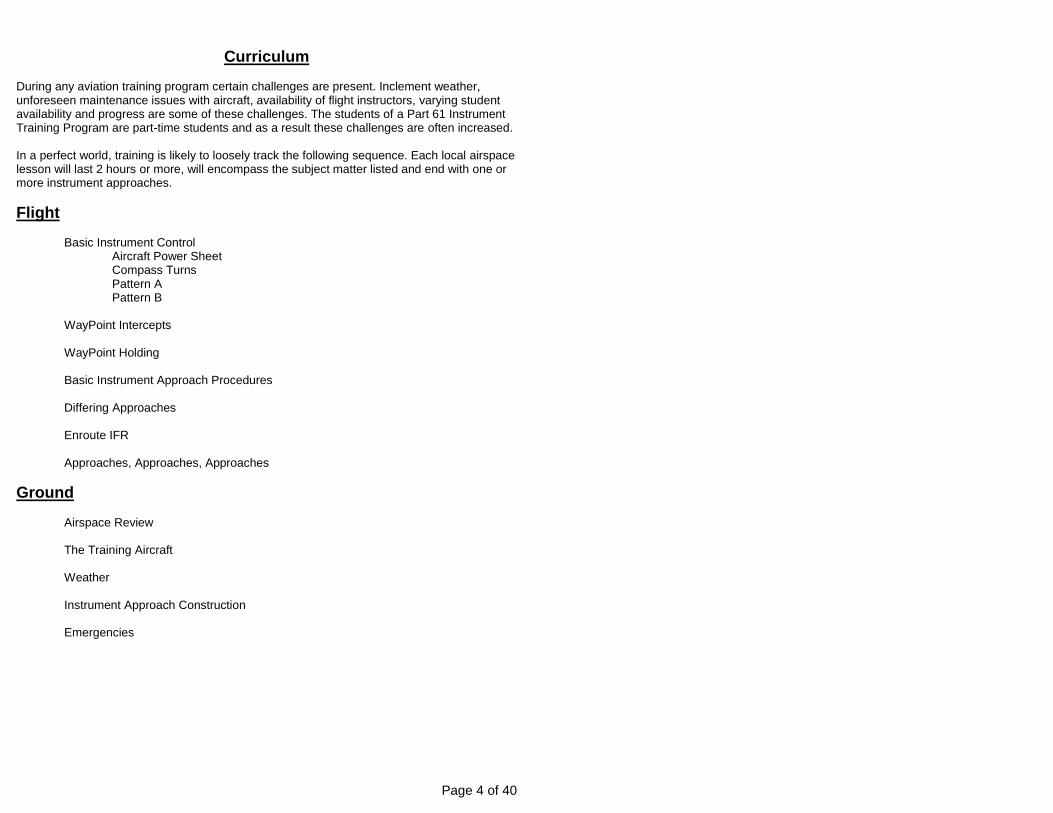
Curriculum During any aviation training program certain challenges are present. Inclement weather, unforeseen maintenance issues with aircraft, availability of flight instructors, varying student availability and progress are some of these challenges. The students of a Part 61 Instrument Training Program are part-time students and as a result these challenges are often increased. In a perfect world, training is likely to loosely track the following sequence. Each local airspace lesson will last 2 hours or more, will encompass the subject matter listed and end with one or more instrument approaches.
Flight
Basic Instrument Control Aircraft Power Sheet
Compass Turns Pattern A Pattern B WayPoint Intercepts WayPoint Holding Basic Instrument Approach Procedures Differing Approaches Enroute IFR Approaches, Approaches, Approaches
Ground
Airspace Review The Training Aircraft Weather Instrument Approach Construction Emergencies
Page 5 of 40
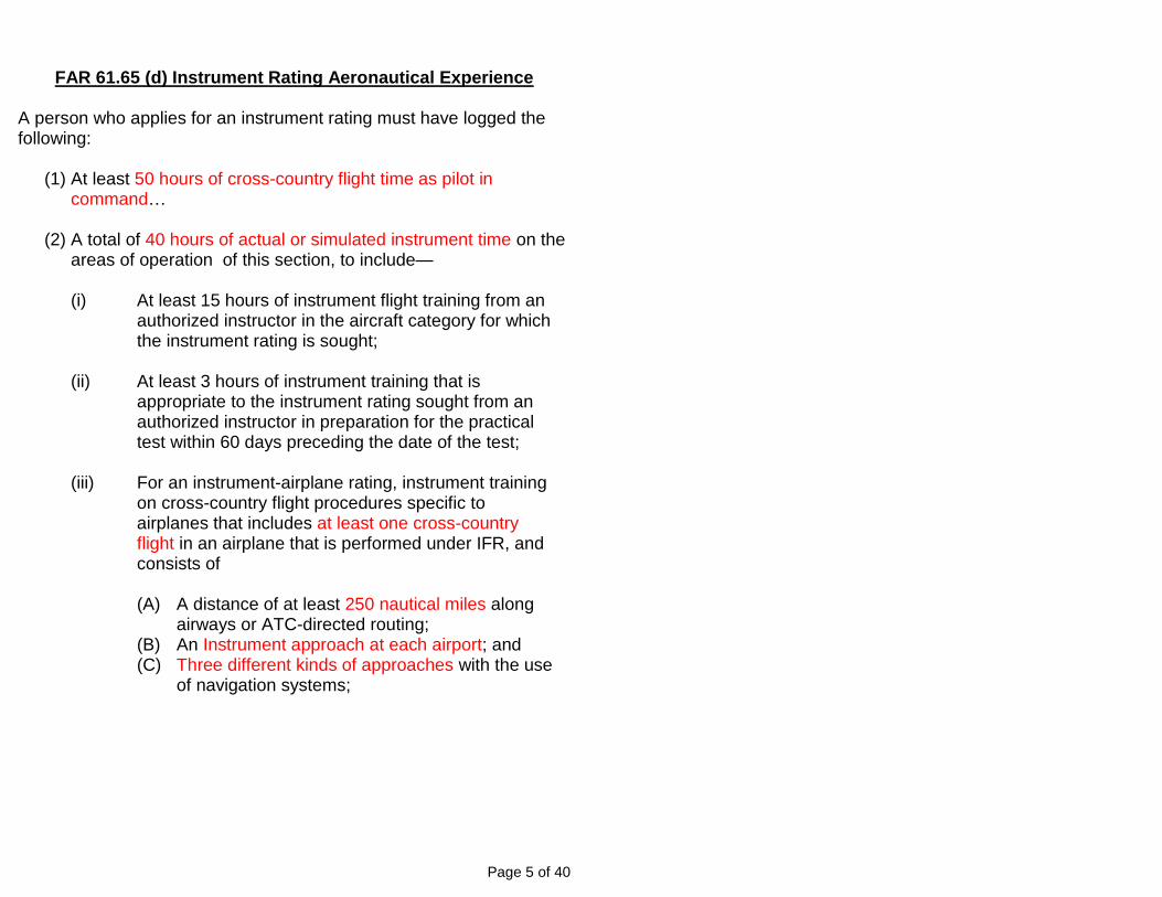
FAR 61.65 (d) Instrument Rating Aeronautical Experience
A person who applies for an instrument rating must have logged the following:
(1) At least 50 hours of cross-country flight time as pilot in command…
(2) A total of 40 hours of actual or simulated instrument time on the
areas of operation of this section, to include—
(i) At least 15 hours of instrument flight training from an authorized instructor in the aircraft category for which the instrument rating is sought;
(ii) At least 3 hours of instrument training that is
appropriate to the instrument rating sought from an authorized instructor in preparation for the practical test within 60 days preceding the date of the test;
(iii) For an instrument-airplane rating, instrument training
on cross-country flight procedures specific to airplanes that includes at least one cross-country flight in an airplane that is performed under IFR, and consists of (A) A distance of at least 250 nautical miles along
airways or ATC-directed routing; (B) An Instrument approach at each airport; and (C) Three different kinds of approaches with the use
of navigation systems;
Page 6 of 40
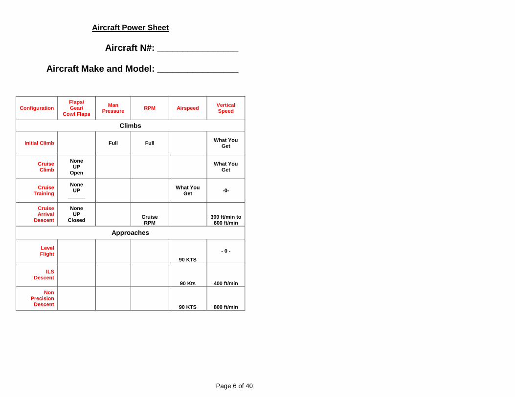
Aircraft Power Sheet
Aircraft N#: ________________
Aircraft Make and Model: ________________
Configuration Flaps/ Gear/
Cowl Flaps
Man Pressure
RPM Airspeed Vertical Speed
Climbs
Initial Climb Full Full What You
Get
Cruise Climb
None UP
Open
What You
Get
Cruise Training
None UP
______
What You
Get -0-
Cruise Arrival
Descent
None UP
Closed
Cruise RPM
300 ft/min to 600 ft/min
Approaches
Level Flight
90 KTS
- 0 -
ILS Descent
90 Kts 400 ft/min
Non Precision
Descent 90 KTS 800 ft/min
Page 7 of 40
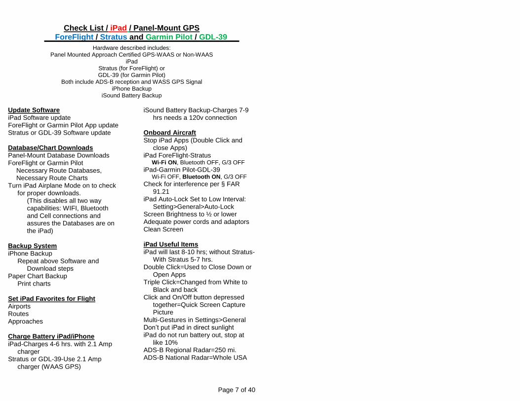
Check List / iPad / Panel-Mount GPS ForeFlight / Stratus and Garmin Pilot / GDL-39
Hardware described includes: Panel Mounted Approach Certified GPS-WAAS or Non-WAAS
iPad Stratus (for ForeFlight) or GDL-39 (for Garmin Pilot)
Both include ADS-B reception and WASS GPS Signal iPhone Backup
iSound Battery Backup
Update Software iPad Software update ForeFlight or Garmin Pilot App update Stratus or GDL-39 Software update Database/Chart Downloads Panel-Mount Database Downloads ForeFlight or Garmin Pilot
Necessary Route Databases, Necessary Route Charts
Turn iPad Airplane Mode on to check for proper downloads.
(This disables all two way capabilities: WIFI, Bluetooth and Cell connections and assures the Databases are on the iPad)
Backup System iPhone Backup
Repeat above Software and Download steps
Paper Chart Backup Print charts
Set iPad Favorites for Flight Airports Routes Approaches Charge Battery iPad/iPhone iPad-Charges 4-6 hrs. with 2.1 Amp
charger Stratus or GDL-39-Use 2.1 Amp
charger (WAAS GPS)
iSound Battery Backup-Charges 7-9 hrs needs a 120v connection
Onboard Aircraft Stop iPad Apps (Double Click and
close Apps) iPad ForeFlight-Stratus
Wi-Fi ON, Bluetooth OFF, G/3 OFF
iPad-Garmin Pilot-GDL-39 Wi-Fi OFF, Bluetooth ON, G/3 OFF
Check for interference per § FAR 91.21
iPad Auto-Lock Set to Low Interval: Setting>General>Auto-Lock
Screen Brightness to ½ or lower Adequate power cords and adaptors Clean Screen iPad Useful Items iPad will last 8-10 hrs; without Stratus-
With Stratus 5-7 hrs. Double Click=Used to Close Down or
Open Apps Triple Click=Changed from White to
Black and back Click and On/Off button depressed
together=Quick Screen Capture Picture
Multi-Gestures in Settings>General Don’t put iPad in direct sunlight iPad do not run battery out, stop at
like 10% ADS-B Regional Radar=250 mi. ADS-B National Radar=Whole USA
Page 8 of 40
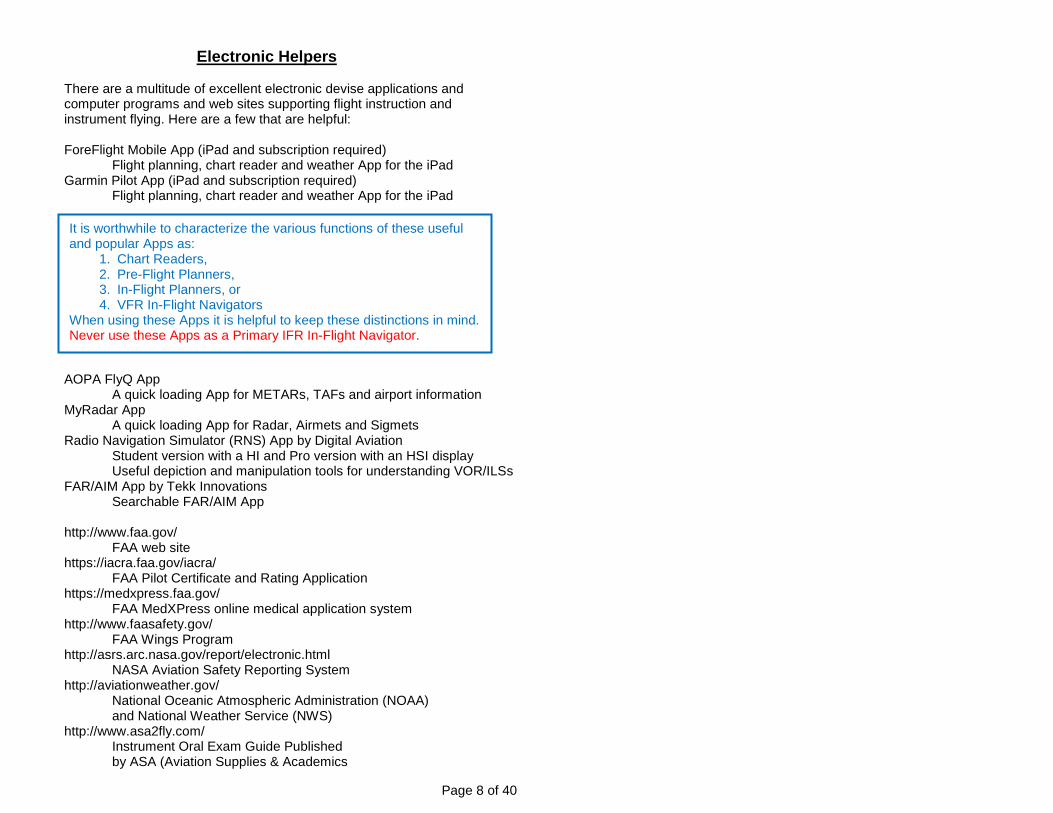
Electronic Helpers There are a multitude of excellent electronic devise applications and computer programs and web sites supporting flight instruction and instrument flying. Here are a few that are helpful: ForeFlight Mobile App (iPad and subscription required) Flight planning, chart reader and weather App for the iPad Garmin Pilot App (iPad and subscription required) Flight planning, chart reader and weather App for the iPad AOPA FlyQ App A quick loading App for METARs, TAFs and airport information MyRadar App A quick loading App for Radar, Airmets and Sigmets Radio Navigation Simulator (RNS) App by Digital Aviation Student version with a HI and Pro version with an HSI display Useful depiction and manipulation tools for understanding VOR/ILSs FAR/AIM App by Tekk Innovations Searchable FAR/AIM App http://www.faa.gov/ FAA web site https://iacra.faa.gov/iacra/ FAA Pilot Certificate and Rating Application https://medxpress.faa.gov/ FAA MedXPress online medical application system http://www.faasafety.gov/ FAA Wings Program http://asrs.arc.nasa.gov/report/electronic.html NASA Aviation Safety Reporting System http://aviationweather.gov/ National Oceanic Atmospheric Administration (NOAA) and National Weather Service (NWS) http://www.asa2fly.com/ Instrument Oral Exam Guide Published by ASA (Aviation Supplies & Academics
It is worthwhile to characterize the various functions of these useful and popular Apps as:
1. Chart Readers, 2. Pre-Flight Planners, 3. In-Flight Planners, or 4. VFR In-Flight Navigators
When using these Apps it is helpful to keep these distinctions in mind. Never use these Apps as a Primary IFR In-Flight Navigator.
Page 9 of 40
http://www.duats.com/ CSC DUATS FAA Weather, Flight Planning and Flight Plan Filing http://www.FLTPlan.com An excellent on-line full featured flight planning tool http://www.wunderground.com/ndfdimage/viewimage Long term (7 day) weather forecasting http://www.IFR-Magazine.com A bit advanced, but a great way to stay in the IFR game http://www.aopa.org/ Airplane Owners and Pilots Association http://www.eaa.org/ Experimental Aircraft Association There are several FAA test prep Apps and Web Sites available. Most have a subscription fee but some are free. If you are going to use one you must be careful to get an app that is up-to-date and is being supported. The only way to do this is to search the current FAA Test Preps available. CAUTION: New Apps and other Web Sites and programs are being developed continually and ones that have been relied upon are sometimes disturbingly discontinued or left unsupported. Keep well informed about what is available and what may be have been abandoned.

Page 10 of 40
IFR Re-Check
Before you Power Up Have You Checked?
1) Charts and Approach Plates 2) GPS Up-to-date & Operable 3) VOR Tolerance Checks 4) Alternate Static Check 5) Lights/Beacon/Strobe Check 6) Pitot Tube Hot 7) Pitot Static System Check 8) Circuit Breakers Checked 9) Attitude Indicator Works 10) Turn Coordinator Works 11) Heading Indicator Works 12) VSI to –0– Check 13) Set Radios for IFR Route 14) Set Radios for Departure Airport Return 15) Lights/Beacon//Strobe On 16) Camera-Transponder On 17) Re-set Altimeter 18) Heading to Compass 19) Correct Runway Check 20) Time Off 21) Spin Up Gyros

Page 11 of 40
GUMPS Checklist
Gas
Fuel Tanks Boost Pump
Undercarriage
Landing Gear Flaps Cowl Flaps
Mixture
Richen Fuel Mixture
Prop
Prop Forward
Safety
Seat Belts Lights
Emergency- 1-Control Pitch 2-Start to Best Glide 3-Fuel Selector & Pump 4-Mags Switch 5-Fuses 6-Landing Area-Wind 7-Communications 8-121.5 7700 9-Flaps when Made
Scott O’Brien CFII & MEI 3551 Lakeshore Dr. Tallahassee, FL 32312 850-284-9310

Page 12 of 40
Heading Indicator Right Hold Hints

Page 13 of 40
Heading Indicator Left Hold Hints

Page 14 of 40
WAYPOINT Intercepts
OBS
Dial OBS (VOR or GPS-OBS) to: Desired Heading Going to Waypoint, or
Desired Radial Going From Waypoint
CDI
45°
To/From Indicator
Fly This Heading to Intercept Course at 45°
Page 15 of 40
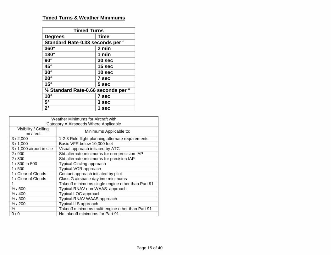
Timed Turns & Weather Minimums
Timed Turns
Degrees Time
Standard Rate-0.33 seconds per °
360° 2 min
180° 1 min
90° 30 sec
45° 15 sec
30° 10 sec
20° 7 sec
15° 5 sec
½ Standard Rate-0.66 seconds per °
10° 7 sec
5° 3 sec
2° 1 sec
Weather Minimums for Aircraft with Category A Airspeeds Where Applicable
Visibility / Ceiling mi / feet
Minimums Applicable to:
3 / 2,000 1-2-3 Rule flight planning alternate requirements
3 / 1,000 Basic VFR below 10,000 feet
3 / 1,000 airport in site Visual approach initiated by ATC
2 / 900 Std alternate minimums for non-precision IAP
2 / 800 Std alternate minimums for precision IAP
1 / 800 to 500 Typical Circling approach
1 / 500 Typical VOR approach
1 / Clear of Clouds Contact approach initiated by pilot
1 / Clear of Clouds Class G airspace daytime minimums
1 Takeoff minimums single engine other than Part 91
½ / 500 Typical RNAV non-WAAS approach
½ / 400 Typical LOC approach
½ / 300 Typical RNAV WAAS approach
½ / 200 Typical ILS approach
½ Takeoff minimums multi-engine other than Part 91
0 / 0 No takeoff minimums for Part 91

Page 16 of 40
Pattern A
Start at Normal Cruise
30 Sec
1 Min
1 Min
60 Sec
15 Sec
2 Min
Change To Low Cruise
45 Sec
15 Sec
1 Min 15 Sec
2 Min
60 Sec
Change To Low Cruise
Go to Normal Cruise
Go to Normal Cruise
END
60 Sec
2 Min 1 Min
Page 17 of 40
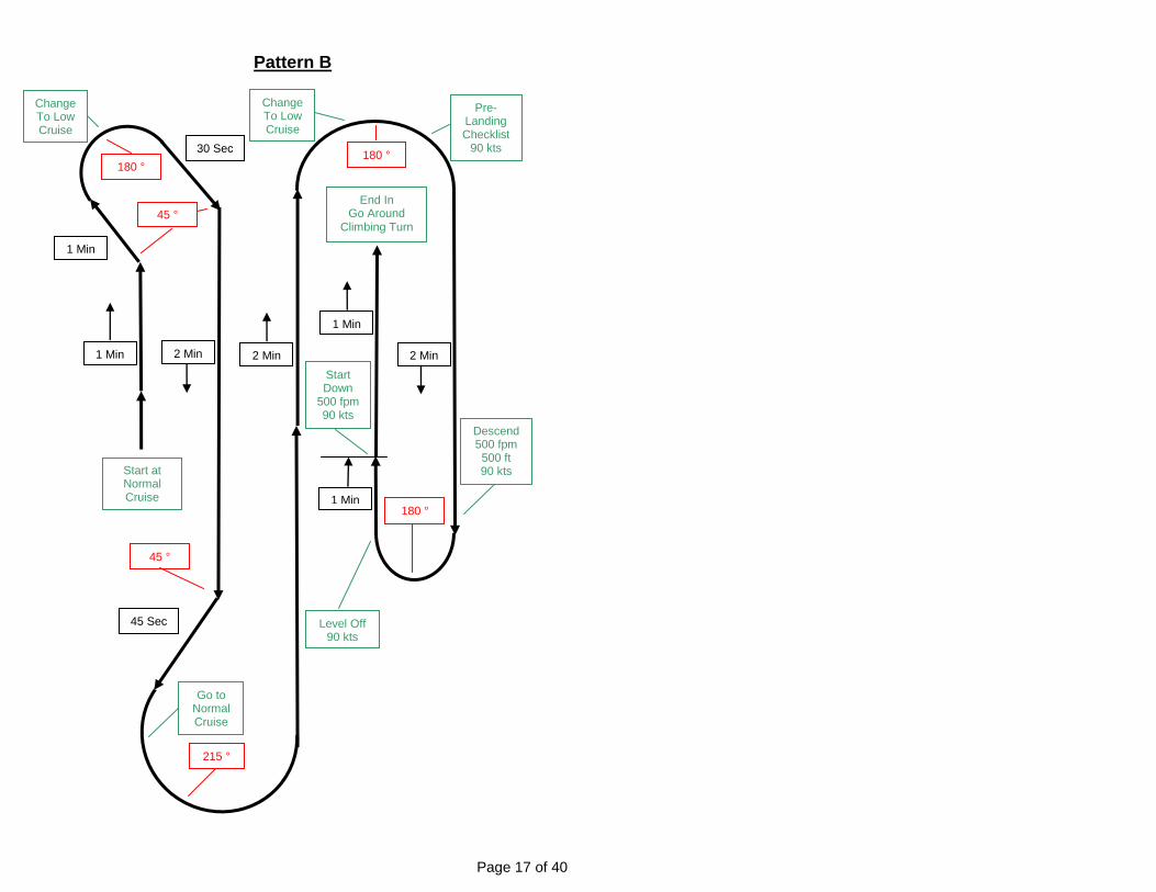
Pattern B
Start at Normal Cruise
30 Sec
1 Min
1 Min
180 °
45 °
2 Min
Change To Low Cruise
45 Sec
45 °
215 °
2 Min
180 °
Start Down
500 fpm 90 kts
End In Go Around
Climbing Turn
180 °
2 Min
1 Min
Change To Low Cruise
Go to Normal Cruise
Pre- Landing Checklist
90 kts
Descend 500 fpm 500 ft 90 kts
Level Off 90 kts
1 Min

Page 18 of 40
Climb Gradient Table

Page 19 of 40
WAAS Approaches
Description Approach Type
System Sensitivity Glidepath Std Min
LPV Localizer Performance with Vertical Guidance
APV-Precision GPS-WAAS L&V Angular GPS Derived 250’
LP Localizer Performance Non-Precision GPS WAAS L Angular None 300’
LNAV / VNAV Lateral & Vertical Navigation
APV-Precision GPS-WAAS L&V or Barometric V
Parallel GPS Derived 350’
LNAV + V Adversary Glide Path Non-Precision GPS-WAAS V Parallel Math Calculation 400’
LNAV Lateral Navigation (Basic GPS)
Non-Precision Basic GPS Non-WAAS
Parallel None 400’
Applicable terrain, obstacle and missed approach criteria surrounding the airport determine if a WAAS approach is enabled as an LPV, LP, LVAV / VNAV or LNAV approach.
Non-Precision = No Vertical Guidance / has an MDA-Minimum Descent Altitude (Dive and Fly Approach)
APV-Precision = Vertical Guidance / has a DA-Descent Altitude (Stabilized Approach)
APV Approaches (Approach with Vertical Guidance) are the RNAV equivalent of ILS Approaches.
APVs have Glide Paths - ILS systems have Glide Slopes
ILS Glide Slopes are depicted with Green Diamonds on Electronic Flight Information System (EFIS) displays
APV Glide Paths are depicted with Magenta Diamonds on Electronic Flight Information System (EFIS) displays
LNAV and LNAV / VNAV approaches have the same terrain clearance specifications, thus you can fly the Glide Path of an LNAV / VNAV to LNAV minimums if the LNAV minimums are lower.
LNAV Approaches that display an Advisory Glide Path are LNAV + V Approaches. LNAV + V Approaches are simply LNAV Approaches that facilitate a Stabilized Approach rather than a Dive and Fly Approach. LNAV + V Approaches are not delineated as such on Approach Plates as they are simply LNAV Approaches with LNAV minimums. But below published MDA the Advisory Glide Path does not always guarantee terrain clearance from the MDA to the Missed Approach Point. LNAV + V Approaches have mathematically calculated Glide Paths created by chart vendors and not the FAA.
LNAV + V Approaches require WAAS and generally are included in vendor data bases only when RNAV Approach Plates 1) have LNAV minimums, 2) do not provide for LNAV / VNAV minimums or LP minimums, and 3) have a non “zero” VDA (Vertical Descent Angle) provided by the FAA to data base vendors. When flying an LNAV Approach with a WAAS capable unit and the unit displays LNAV + V as the approach and a Glide Path needle comes alive, you know you are flying a LNAV + V Approach. Be Careful Below MDA, you are on your own for terrain clearance.
Parallel Sensitivity Angular Sensitivity

Page 20 of 40
Instrument Pilot Practical Test Review Practice Flight Test Ground Training Taxi Instrument Check Holding Pattern Discussion Hood Climb out Turns GPS Discussion
Constant Airspeed Weather Discussion Constant Rate Clearance Discussion
Hood Straight and Level DME Arcs Discussion Hood Slow Flight Navaid Identification Hood Steep Turns Minimum Equipment Discussion Hood Turns Review PTS/Task Failure
Compass Turns Circling Approach Discussion Timed Turns Hood Unusual Attitudes Hood Partial Panel Hood Holding Hood DME Arc Approaches - Three
Non-precision VOR Non-precision Localizer Non-precision GPS if Equipped Precision ILS Partial Panel Approach Missed Approach Circling Approach
Page 21 of 40
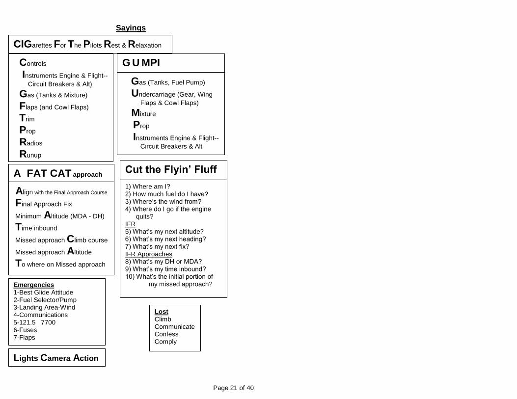
Sayings
G U MPI
Gas (Tanks, Fuel Pump)
Undercarriage (Gear, Wing
Flaps & Cowl Flaps)
Mixture
Prop
Instruments Engine & Flight--
Circuit Breakers & Alt
Emergencies 1-Best Glide Attitude 2-Fuel Selector/Pump 3-Landing Area-Wind 4-Communications 5-121.5 7700 6-Fuses 7-Flaps
Lights Camera Action
CIGarettes For The Pilots Rest & Relaxation
Controls
Instruments Engine & Flight--
Circuit Breakers & Alt)
Gas (Tanks & Mixture)
Flaps (and Cowl Flaps)
Trim
Prop
Radios
Runup
A FAT CAT approach
Align with the Final Approach Course
Final Approach Fix
Minimum Altitude (MDA - DH)
Time inbound
Missed approach Climb course
Missed approach Altitude
To where on Missed approach
Cut the Flyin’ Fluff
1) Where am I? 2) How much fuel do I have? 3) Where’s the wind from? 4) Where do I go if the engine quits? IFR 5) What’s my next altitude? 6) What’s my next heading? 7) What’s my next fix? IFR Approaches 8) What’s my DH or MDA? 9) What’s my time inbound? 10) What’s the initial portion of
my missed approach?
Lost Climb Communicate Confess Comply
Page 22 of 40
Regulations The reality of operating an aircraft under Instrument Flight Rules (IFR) necessitates a pilot joining a partnership of many people including pilots, controllers, aircraft operators, manufacturers, educators and regulators. The goal of this partnership is the most efficient sequencing of air traffic so as to maximize the needs of all partners, considering all reasonable weather conditions, while maintaining the highest level of safety possible. Acquiring the necessary skills in order to become an effective member of this IFR partnership requires one to master an understanding of a multitude of rules. These rules by necessity are complicated and defy a coherent sequence of categorization. Nevertheless these rules must be mastered. Follows is a sequence of rules pertaining specifically to private pilot/instrument operating privileges for “light” aircraft operated at altitudes generally associated with this type of flying. No attempt has been made to include regulations pertaining to IFR flight planning or Commercial or ATP privileges. Various Federal Aviation Regulations (FARs) are cited along with excerpts from the Aeronautical Information Manual (AIM). Caution must be advised. Rules change and paraphrasing and literary license have been extensively used in order to simplify as much as possible the various rules for the edification of the target audience. Should a comprehensive view of these rules be sought, then one must look to the full and inclusive text and many other rules not cited. Red Text is particularly important, Black Text is from the AIM or FARs, Green Text is added for clarity and further clarification. Definition of ATC Clearance FAR § 1.1 Air traffic clearance means an authorization by air traffic control, for the purpose of preventing collision between known aircraft, for an aircraft to precede under specified traffic conditions within controlled airspace. Controlled Airspace AIM Part 3-2-1 a. Controlled Airspace. A generic term that covers the different classifications of airspace (Class A, Class B, Class C, Class D, and Class E airspace) [Class G airspace is not Controlled Airspace] and defined dimensions within which air traffic control service is provided to IFR flights and to VFR flights… c. IFR Separation. Standard IFR separation is provided to all aircraft operating under IFR in controlled airspace.

Page 23 of 40
Clearance and flight plan required FAR § 91.173 No person may operate an aircraft in controlled airspace under IFR unless that person has—
(a) Filed an IFR flight plan [or has been issued a “pop-up” clearance by an ATC sector to operate within that sector]; and (b) Received an appropriate ATC clearance.
[“Cleared to …..” carries with it the legal significance that one may operate below VFR weather minimums] Clearance Items AIM 4-4-3 a. Clearance Limit. The traffic clearance issued prior to departure will normally authorize flight to the airport of intended landing. Many airports and associated NAVAIDs [have] the same name and/or identifier, so care should be exercised to ensure a clear understanding of the clearance limit. When the clearance limit is the airport of intended landing, the clearance should contain the airport name followed by the word “airport.” Under certain conditions, a clearance limit may be a NAVAID or other fix. …. Under certain conditions, at some locations a short-range clearance procedure is utilized whereby a clearance is issued to a fix within or just outside of the terminal area and pilots are advised of the frequency on which they will receive the long-range clearance direct from the center controller. Emergency Authority AIM section 6-1-1 a. The pilot-in-command of an aircraft is directly responsible for and is the final authority as to the operation of that aircraft. In an emergency requiring immediate action, the pilot-in-command may deviate from any rule …, to the extent required to meet that emergency. b. If the emergency ... is used to deviate from the provisions of an ATC clearance, the pilot-in-command must notify ATC as soon as possible and obtain an amended clearance. c. Unless deviation is necessary under the emergency authority …, pilots of IFR flights experiencing two‐way radio communications failure are expected to adhere to the procedures prescribed under [FAR § 91.185]. Two-way radio communication failure FAR § 91.185 (a) General. Unless otherwise authorized by ATC, each pilot who has two-way radio communications failure when operating under IFR shall comply with the rules of this section.

Page 24 of 40
(b) VFR conditions. If the failure occurs in VFR conditions [VMC], or if VFR conditions are encountered after the failure, each pilot shall continue the flight under VFR and land as soon as practicable. (c) IFR conditions. If the failure occurs in IFR conditions [IMC], or if [VMC conditions are not encountered] each pilot shall continue the flight according to the following:
(1) Route.
(i) By the route assigned in the last ATC clearance received; (ii) If being radar vectored, by the direct route from the point of radio failure to the fix, route, or airway specified in the vector clearance; (iii) In the absence of an assigned route, by the route that ATC has advised may be expected in a further clearance; or (iv) In the absence of an assigned route or a route that ATC has advised may be expected in a further clearance, by the route filed in the flight plan.
(2) Altitude. At the highest of the following altitudes or flight levels for the route segment being flown:
(i) The altitude or flight level assigned in the last ATC clearance received; (ii) The minimum altitude … for IFR operations; or (iii) The altitude or flight level ATC has advised may be expected in a further clearance.
(3) Leave clearance limit.
(i) When the clearance limit is a fix from which an approach begins, commence descent or descent and approach as close as possible to the expect-further-clearance time if one has been received, or if one has not been received, as close as possible to the estimated time of arrival as calculated from the filed or amended (with ATC) estimated time en route. (ii) If the clearance limit is not a fix from which an approach begins, leave the clearance limit at the expect-further-clearance time if one has been received, or if none has been received, upon arrival over the clearance limit, and proceed to a fix from which an approach begins and commence descent or descent and approach as close as possible to the estimated time of arrival as calculated from the filed or amended (with ATC) estimated time en route.
Page 25 of 40
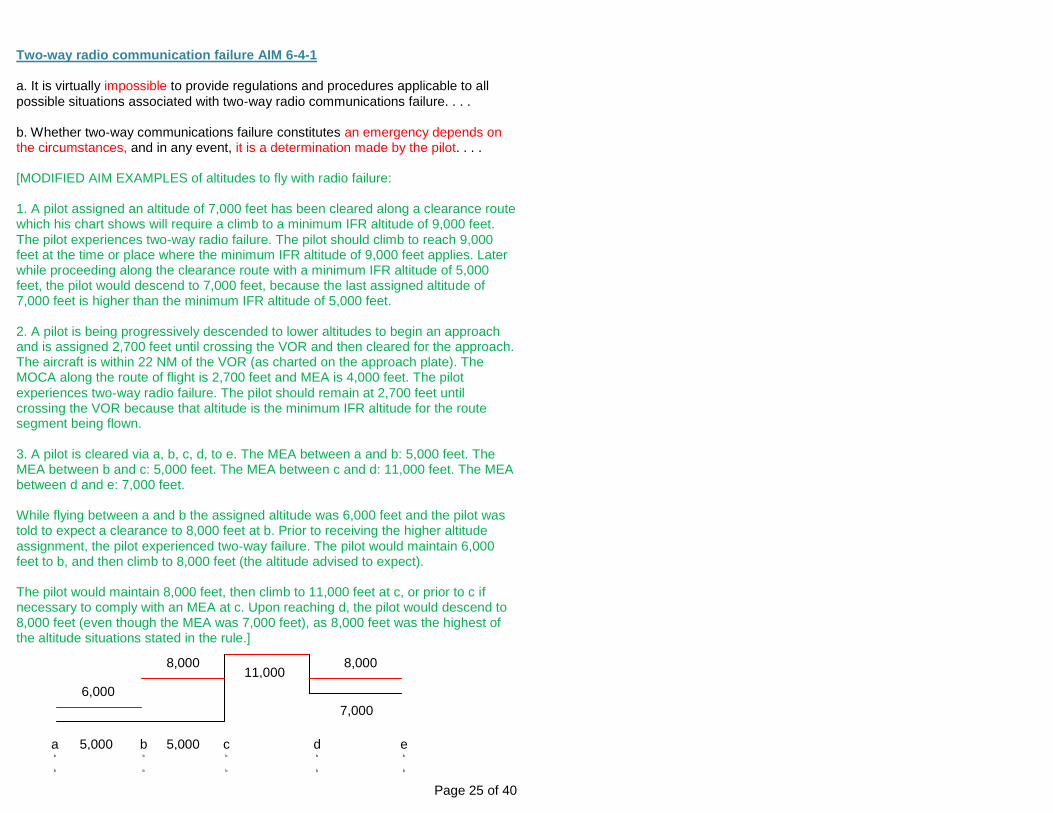
Two-way radio communication failure AIM 6-4-1 a. It is virtually impossible to provide regulations and procedures applicable to all
possible situations associated with two‐way radio communications failure. . . .
b. Whether two‐way communications failure constitutes an emergency depends on the circumstances, and in any event, it is a determination made by the pilot. . . . [MODIFIED AIM EXAMPLES of altitudes to fly with radio failure: 1. A pilot assigned an altitude of 7,000 feet has been cleared along a clearance route which his chart shows will require a climb to a minimum IFR altitude of 9,000 feet.
The pilot experiences two‐way radio failure. The pilot should climb to reach 9,000 feet at the time or place where the minimum IFR altitude of 9,000 feet applies. Later while proceeding along the clearance route with a minimum IFR altitude of 5,000 feet, the pilot would descend to 7,000 feet, because the last assigned altitude of 7,000 feet is higher than the minimum IFR altitude of 5,000 feet. 2. A pilot is being progressively descended to lower altitudes to begin an approach and is assigned 2,700 feet until crossing the VOR and then cleared for the approach. The aircraft is within 22 NM of the VOR (as charted on the approach plate). The MOCA along the route of flight is 2,700 feet and MEA is 4,000 feet. The pilot
experiences two‐way radio failure. The pilot should remain at 2,700 feet until crossing the VOR because that altitude is the minimum IFR altitude for the route segment being flown. 3. A pilot is cleared via a, b, c, d, to e. The MEA between a and b: 5,000 feet. The MEA between b and c: 5,000 feet. The MEA between c and d: 11,000 feet. The MEA between d and e: 7,000 feet. While flying between a and b the assigned altitude was 6,000 feet and the pilot was told to expect a clearance to 8,000 feet at b. Prior to receiving the higher altitude
assignment, the pilot experienced two‐way failure. The pilot would maintain 6,000 feet to b, and then climb to 8,000 feet (the altitude advised to expect). The pilot would maintain 8,000 feet, then climb to 11,000 feet at c, or prior to c if necessary to comply with an MEA at c. Upon reaching d, the pilot would descend to 8,000 feet (even though the MEA was 7,000 feet), as 8,000 feet was the highest of the altitude situations stated in the rule.]
ab
b
eb
b
bb
b
cb
b
db
b
5,000 5,000
11,000
7,000
8,000 8,000
6,000

Page 26 of 40
Takeoff …. under IFR FAR 91.175 (f) Civil airport takeoff minimums. [Takeoff minimums are not prescribed for operations under Part 91. Be Careful!] … Instrument Departure Procedures (DP) - Obstacle Departure Procedures (ODP) and Standard Instrument Departures (SID) AIM Part 5-2-8
[Terminal Procedures Publication (TPP) booklets are becoming a thing of the past due to the increasing use of electronic tablet devices. But an understanding of a TPP booklet remains essential because important airport information can easily be overlooked with the reliance on electronic tablet devices. Each TPP booklet covers IFR airport information for airports located in a specific region of one or more states in the US. Airport information contained in the TPP booklets includes: Instrument Approach Procedures (IAPs or “approach plates”), Departure Procedures (DPs) including Obstacle Departure Procedures (ODPs) and Standard Instrument Departures (SIDs), Standard Terminal Arrival Routes (STARs), legend information concerning the interpretation of IAPs, indexes, and other important general information about instrument flying. Electronic tablet devices are superb for the viewing of approach plates, but without a clear understanding of TPP booklets, electronic tablet devices can be a hindrance when accessing other important information in TPPs. With this in mind, so goes the dialog. There is a separate section in each TPP booklet titled “Take-off Minimums and (OBSTACLE) Departure Procedures”. This section of the TPPs will be referred to as the TAKEOFF MINIMUMS section because this is the designation adopted by both ForeFlight and Garmin Pilot Apps. This TAKEOFF MINIMUMS section is a listing of important information for many airports within the specific region covered by the particular TPP. This TAKEOFF MINIMUMS section is generally not made searchable in Apps like ForeFlight and Garmin Pilot. Rather the whole TAKEOFF MINIMUMS section of the TPP is made available by the App and the pilot needs to scroll the TAKEOFF MINIMUMS section to find any relevant information pertaining to a particular airport. This is a rather simple operation, but it is an inconvenience that must be recognized and dealt with. If a “Triangle ‘T’” symbol is located in the upper left corner on an approach plate (IAP) for an airport, this indicates that there is important information in the TAKEOFF MINIMUMS section. This important information may include the following: 1) That some NOTES are made of the proximity of trees or the like around runway ends (see Apalachicola, FL KAAF) 2) That there is some written but uncharted ODB procedure for one or more of the runways (see Bonifay, FL 1J0), or
Page 27 of 40
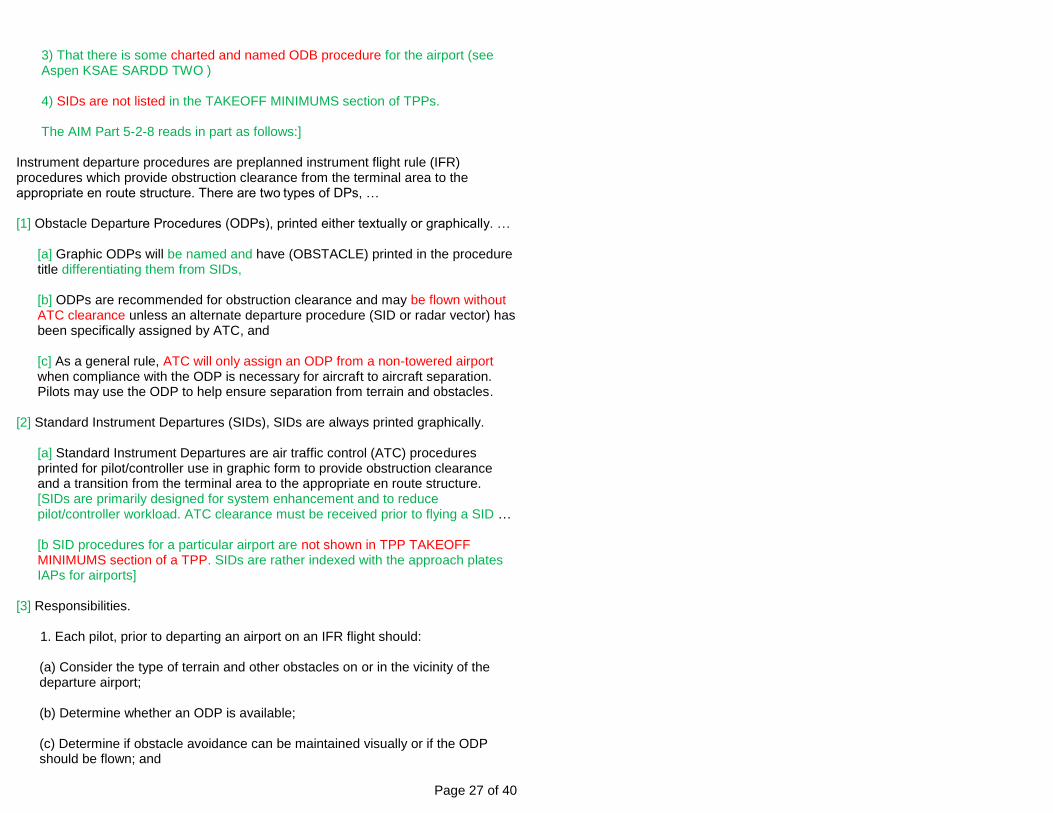
3) That there is some charted and named ODB procedure for the airport (see Aspen KSAE SARDD TWO ) 4) SIDs are not listed in the TAKEOFF MINIMUMS section of TPPs. The AIM Part 5-2-8 reads in part as follows:]
Instrument departure procedures are preplanned instrument flight rule (IFR) procedures which provide obstruction clearance from the terminal area to the appropriate en route structure. There are two types of DPs, … [1] Obstacle Departure Procedures (ODPs), printed either textually or graphically. …
[a] Graphic ODPs will be named and have (OBSTACLE) printed in the procedure title differentiating them from SIDs, [b] ODPs are recommended for obstruction clearance and may be flown without ATC clearance unless an alternate departure procedure (SID or radar vector) has been specifically assigned by ATC, and [c] As a general rule, ATC will only assign an ODP from a non-towered airport when compliance with the ODP is necessary for aircraft to aircraft separation. Pilots may use the ODP to help ensure separation from terrain and obstacles.
[2] Standard Instrument Departures (SIDs), SIDs are always printed graphically.
[a] Standard Instrument Departures are air traffic control (ATC) procedures printed for pilot/controller use in graphic form to provide obstruction clearance and a transition from the terminal area to the appropriate en route structure. [SIDs are primarily designed for system enhancement and to reduce pilot/controller workload. ATC clearance must be received prior to flying a SID … [b SID procedures for a particular airport are not shown in TPP TAKEOFF MINIMUMS section of a TPP. SIDs are rather indexed with the approach plates IAPs for airports]
[3] Responsibilities.
1. Each pilot, prior to departing an airport on an IFR flight should:
(a) Consider the type of terrain and other obstacles on or in the vicinity of the departure airport; (b) Determine whether an ODP is available; (c) Determine if obstacle avoidance can be maintained visually or if the ODP should be flown; and
Page 28 of 40
(d) Consider the effect of degraded climb performance and the actions to take in the event of an engine loss during the departure. Pilots should notify ATC as soon as possible of reduced climb capability in that circumstance…
[2.] Pilots operating under 14 CFR Part 91 are strongly encouraged to file and fly a DP at night, during marginal Visual Meteorological Conditions (VMC) and Instrument Meteorological Conditions (IMC), when one is available. … [3.] When used by the controller during departure, the term “radar contact” should not be interpreted as relieving pilots of their responsibility to maintain appropriate terrain and obstruction clearance which may include flying the obstacle DP.
VFR-on-top Clearance AIM 4-4-8 (Useful for Weather and Radar Coverage Issues) a. A pilot on an IFR flight plan operating in VFR weather conditions, may request VFR-on-top in lieu of an assigned altitude. This permits a pilot to select an altitude or flight level of their choice. b. Pilots desiring to climb through a cloud, haze, smoke, or other meteorological formation and then either cancel their IFR flight plan or operate VFR-on-top may request a “Climb to VFR-on-Top”. The ATC authorization must contain either a top report or a statement that no top report is available, and a request to report reaching VFR-on-top. Additionally, the ATC authorization may contain a clearance limit, routing and an alternative clearance if VFR-on-top is not reached by a specified altitude. c. A pilot on an IFR flight plan, operating in VFR conditions, may request to climb/descend in VFR conditions. d. ATC may not authorize VFR-on-top operations unless the pilot requests the operation or (such) a clearance to operate in VFR conditions will result in noise abatement benefits where part of the IFR departure route does not conform to an FAA approved noise abatement route or altitude. e. When operating in VFR conditions with an ATC authorization to “maintain VFR-on-top/maintain VFR conditions” pilots on IFR flight plans must:
1. Fly at the appropriate VFR altitude [that is: East=odd+500 feet; West=even+500]… 2. Comply with the VFR visibility and distance from cloud criteria [Basic VFR Weather Minimums]. 3. Comply with (other) instrument flight rules that are applicable to this flight; i.e., minimum IFR altitudes, position reporting, radio communications, course to be flown, adherence to ATC clearance, etc.

Page 29 of 40
NOTE-Pilots should advise ATC prior to any altitude change [VFR-on-Top Clearance] to ensure the exchange of accurate traffic information. f. ATC authorization to “maintain VFR-on-top” is not intended to restrict pilots so that they must operate only above an obscuring meteorological formation (layer). Instead, it permits operation above, below, between layers, or in areas where there is no meteorological obscuration. It is imperative, however, that pilots understand that clearance to operate “VFR-on-top/VFR conditions” does not imply cancellation of the IFR flight plan. g. Pilots operating VFR-on-top/VFR conditions may receive traffic information from ATC on other pertinent IFR or VFR aircraft. However, aircraft operating in Class B airspace/TRSAs must be separated as required by …, Air Traffic Control. h. ATC will not authorize VFR or VFR-on-top operations in Class A airspace. Cruise Clearance AIM 4-4-3 (Useful for Weather issues)
d. Altitude Data…
3. The term “CRUISE” may be used instead of “MAINTAIN” to assign a block of airspace to a pilot from the minimum IFR altitude up to and including the altitude specified in the cruise clearance. The pilot may level off at any intermediate altitude within this block of airspace. Climb/descent within the block is to be made at the discretion of the pilot. However, once the pilot starts descent and verbally reports leaving an altitude in the block, the pilot may not return to that altitude without additional ATC clearance.
[No need to advise ATC prior of altitude changes (Cruise Clearance) until advising the leaving of the block]
Examples of Clearances Cessna 1234, maintain block 10000 through 8000 Piper 1234, descend via the SUNST Three Arrival Beechcraft 1234, cross WXYZ at and maintain 8000 Cirrus 1234, cross WXYZ at or above 5000 descend and maintain 3000 Maule 1234, maintain 8000 until WXYZ then descend and maintain 6000 Experimental 1234 Cleared contact approach (and, if required) at or below (altitude)
(routing) if not possible (alternative procedures) and advise.
Page 30 of 40
Visual Approach AIM 5-4-23 (need to see airport) a. A visual approach is conducted on an IFR flight plan and authorizes a pilot to proceed visually and clear of clouds to the airport. The pilot must have either the airport or the preceding identified aircraft in sight. This approach must be authorized and controlled by the appropriate air traffic control facility. Reported weather at the airport must have a ceiling at or above 1,000 feet and visibility 3 miles or greater. ATC may authorize this type approach [ATC may and often does initiate this approach] when it will be operationally beneficial. Visual approaches are an IFR procedure conducted under IFR in visual meteorological conditions. Contact Approach AIM 5-4-25 (don’t need to see airport-be careful) a. Pilots operating in accordance with an IFR flight plan, provided they are clear of clouds and have at least 1 mile flight visibility [not necessary to have airport in sight] and can reasonably expect to continue to the destination airport in those conditions, may request ATC authorization for a contact approach. b. Controllers may authorize a contact approach provided:
1. The contact approach is specifically requested by the pilot. ATC cannot initiate this approach. 2. The reported ground visibility at the destination airport is at least 1 statute mile. 3. The contact approach will be made to an airport having a standard or special instrument approach procedure.
c. A contact approach is … [a DANGERIOUS] approach procedure that may be used by a pilot (with prior authorization from ATC) in lieu of conducting an … IAP to an airport. It is not intended for use by a pilot on an IFR flight clearance to operate to an airport not having a published and functioning IAP. Nor is it intended for an aircraft to conduct an instrument approach to one airport and then, when “in the clear,” discontinue that approach and proceed to another airport. In the execution of a contact approach, the pilot assumes the responsibility for obstruction clearance. If radar service is being received, it will automatically terminate when the pilot is instructed to change to advisory frequency. Standard Terminal Arrival (STAR), …. for Arrivals AIM Part 5-4-1 a. A STAR is an ATC coded IFR arrival route established for application to arriving IFR aircraft destined for certain airports. …The purpose … is to simplify clearance delivery procedures and facilitate transition between en route and instrument approach procedures.
1. STAR… procedures may have mandatory speeds and/or crossing altitudes published. Other STARs may have planning information depicted to inform pilots

Page 31 of 40
what clearances or restrictions to “expect.” “Expect” altitudes/speeds are not considered STAR … procedures crossing restrictions unless verbally issued by ATC. NOTE-The “expect” [terminology used on STAR charts including] altitudes/speeds are published so that pilots may have the information for planning purposes. These altitudes/speeds must not be used in the event of lost communications unless ATC has specifically advised the pilot to expect these altitudes/speeds as part of a further clearance. 2. Pilots navigating on STAR … procedures must maintain last assigned altitude until receiving authorization to descend so as to comply with all published/issued restrictions. This authorization will contain the phraseology “DESCEND VIA.” …
b. Pilots of IFR aircraft destined to locations for which STARs have been published may be issued a clearance containing a STAR whenever ATC deems it appropriate. c. Use of STARs requires pilot possession of at least the approved chart. …. As with any ATC clearance or portion thereof, it is the responsibility of each pilot to accept or refuse an issued STAR. Pilots should notify ATC if they do not wish to use a STAR by placing “NO STAR” in the remarks section of the flight plan or by the less desirable method of verbally stating the same to ATC… AIM 5-4-9 Procedure Turn a. A procedure turn is the maneuver prescribed when it is necessary to perform a course reversal to establish the aircraft inbound on an intermediate or final approach course. The procedure turn or hold in lieu of a procedure turn is a required maneuver. [Unless authorized by ATC, the procedure turn or hold in lieu of a procedure turn is not permitted when:]
[1] When the symbol ”NoPT” is shown, [2] When RADAR VECTOR[ING] is provided ….. [3] When conducting timed approaches [4] [When the procedure turn is otherwise not authorized]
1. On U.S. Government charts, a barbed arrow indicates the direction of the outbound course on which the turn is made … 3. When the approach procedure involves a procedure turn, a maximum speed of not greater than 200 knots (IAS) should be observed … Pilots should begin the outbound turn immediately after passing the procedure turn fix. The procedure turn maneuver must be executed within the distance specified in the profile view.

Page 32 of 40
4. A teardrop procedure or penetration turn may be specified in some procedures for a required course reversal … 5. A holding pattern in lieu of a procedure turn may be specified for course reversal in some procedures. … The holding pattern distance or time specified in the profile view must be observed. … The holding pattern maneuver is completed when the aircraft is established on the inbound course after executing the appropriate entry. If cleared for the approach prior to returning to the holding fix, and the aircraft is at the prescribed altitude, additional circuits of the holding pattern are not necessary nor expected by ATC. If pilots elect to make additional circuits to lose excessive altitude or to become better established on course, it is their responsibility to so advise ATC … 6. A procedure turn is not required when an approach can be made directly from a specified intermediate fix [Waypoint Transition] to the final approach fix. …
b. Limitations on Procedure Turns….
2. When a teardrop procedure turn is depicted and a course reversal is required, this type turn must be executed. 3. When a holding pattern replaces a procedure turn, the holding pattern must be followed, except when radar is provided or when NoPT is shown on the approach chart….
[Procedure Turn Options or better stated Course Reversal Options: (YOU MUST COMPLY WITH ONE OF THESE)
1. “Traditional” Procedure Turn (as charted) 2. Hold (In Lieu of a Traditional Procedure Turn as charted) 3. Teardrop or Penetration Turn (as charted) 4. DME Arc (as charted) 5. Waypoint Transition (as charted) 6. GPS “T” Approach (as charted) 7. Radar Vectors (to the Final Approach Course), or 8. Another ATC Approved procedure
(IF THERE IS ANY DOUBT ABOUT A COURSE REVERSAL-REQUEST A CLEARANCE)]
…Landing under IFR § FAR 91.175 (a) Instrument approaches to civil airports. …when it is necessary to use an instrument approach to a civil airport, [and the pilot cannot fly or chooses not to fly a visual or contact approach] each person operating an aircraft [must use a standard instrument approach procedure (IAP)] … (c) Operation below Decision Height (DH-precision approach) or Minimum Descent Altitude (MDA-precision approach). … no pilot may operate an aircraft ... at an

Page 33 of 40
airport below the authorized MDA or continue an approach below the authorized DH unless ---
(1) The aircraft is continuously in a position from which a descent to a landing on the intended runway can be made at a normal rate of descent using normal maneuvers, … (2) The flight visibility is not less than the visibility prescribed in the standard instrument approach being used: and (3)… at least one of the following visible references for the intended runway is distinctly visible and identified by the pilot: [THE RUNWAY ENVIROMENT]
(i) The approach light system, except that the pilot may not descend below 100 above the touchdown zone elevation using the approach lights as a reference unless the red terminating bars or the red side row bars are also distinctly visible and identifiable.
(ii) The threshold. (iii) The Threshold markings. (iv) The threshold light. (v) The runway identifier lights. (vi) The visual approach slope indicator. (vii) The touchdown zone or touchdown zone markings. (viii) The touchdown zone lights. (ix) The runway or runway markings. (x) The runway lights.
(d) Landing. No pilot operating an aircraft… may land that aircraft when --
(2) … the flight visibility is less than the visibility prescribed in the standard instrument approach procedure [IAP] being used.
[Flight visibility will be identical to ASOS reported visibility unless you can prove different. Good luck. Thus, if the reported visibility is below the IAP minimums don’t even attempt the approach because you can’t land anyway. The same does not apply to a ceiling below minimums. You are not prohibited from “taking a look”] (e) Missed Approach procedures. Each pilot operating an aircraft … shall immediately execute an appropriate missed approach procedure when either of the following conditions exist:
(1) Whenever operating an aircraft pursuant to paragraph (c) … of this section and the requirements of that paragraph are not met at either of the following times:
(i) When the aircraft is being operated below MDA; or
Page 34 of 40
(ii) Upon arrival at the missed approach point … and at any time after that until touchdown.
(2) Whenever an identifiable part of the airport is not distinctly visible to the pilot during a circling maneuver at or above MDA, unless the inability to see an identifiable part of the airport results only from a normal bank of the aircraft during the circling approach.
(i) … use of radar in instrument approach procedures. When radar is approved at certain locations for ATC purposes, it may be used not only for surveillance and precision radar approaches … but also may be used in conjunction with instrument approach procedures predicated on other types of navigational aids. Radar vectors [to the final approach course] may be authorized to provide course guidance through the segments of an approach to the final course or fix. … the pilot, … shall, ... maintain the last altitude assigned to that pilot until the aircraft is established on a segment of a published … instrument approach procedure unless a different altitude is assigned by ATC. After the aircraft is so established, published altitudes apply to the descent within each succeeding ... approach segment unless a different altitude is assigned by ATC. Upon reaching the final approach course or fix, the pilot may either complete the instrument approach in accordance with the procedure approved for the facility or continue a surveillance or precision radar approach to a landing…. Maintenance required FAR § 91.405 Each owner or operator of an aircraft—
(a) Shall have that aircraft inspected …. and shall between required inspections…, have discrepancies repaired … (b) Shall ensure that … appropriate entries [are made] in the aircraft maintenance records indicating the aircraft has been approved for return to service;… (d) When listed discrepancies include inoperative instruments or equipment, shall ensure that a placard has been installed [indicating the non-essential instrument is inoperative].
FAR § 43.9 Content, form, and disposition of maintenance, preventive maintenance, rebuilding, and alteration records (a) Maintenance record entries. …, each person who maintains, performs preventive maintenance, rebuilds, or alters an aircraft, airframe, aircraft engine, propeller, appliance, or component part shall make an entry in the maintenance record of that equipment containing the following information:
(1) A description … of work performed.
Page 35 of 40
(2) The date of completion of the work performed. (3) The name of the person performing the work … (4) If the work performed on the aircraft, airframe, aircraft engine, propeller, appliance, or component part has been performed satisfactorily, the signature, certificate number, and kind of certificate held by the person approving the work. The signature constitutes the approval for return to service only for the work performed….
Persons authorized to perform maintenance, preventive maintenance, rebuilding, and alterations FAR § 43.3 (a) Except as provided in this section … no person may maintain, rebuild, alter, or perform preventive maintenance on an aircraft, airframe, aircraft engine, propeller, appliance, or component part to which this part applies… (g) …the holder of a pilot certificate issued under part 61 may perform preventive maintenance on any aircraft owned or operated by that pilot which is not used under part 121, 129, or 135 of this chapter…. (k) Updates of databases (GPS Data Bases) in installed avionics meeting the conditions of this paragraph are not considered maintenance and may be performed by pilots provided:
(1) The database upload is:
(i) Initiated from the flight deck; (ii) Performed without disassembling the avionics unit; and (iii) Performed without the use of tools and/or special equipment.
(2) The pilot must comply with the certificate holder's procedures or the manufacturer's instructions.
VOR equipment check for IFR operations FAR § 91.171 (a) No person may operate a civil aircraft under IFR using the VOR system of radio navigation unless the VOR equipment of that aircraft—….
(2) Has been operationally checked within the preceding 30 days, and was found to be within the limits of the permissible indicated bearing error set [below].
(b) Except as provided in paragraph (c) of this section, each person conducting a VOR check under paragraph (a)(2) of this section shall—
(1) Use, at the airport of intended departure, an FAA-operated or approved test signal [VOT]…(the maximum permissible indicated bearing error is plus or minus 4 degrees); or
Page 36 of 40
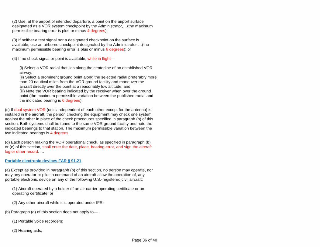
(2) Use, at the airport of intended departure, a point on the airport surface designated as a VOR system checkpoint by the Administrator,…(the maximum permissible bearing error is plus or minus 4 degrees); (3) If neither a test signal nor a designated checkpoint on the surface is available, use an airborne checkpoint designated by the Administrator …(the maximum permissible bearing error is plus or minus 6 degrees); or (4) If no check signal or point is available, while in flight—
(i) Select a VOR radial that lies along the centerline of an established VOR airway; (ii) Select a prominent ground point along the selected radial preferably more than 20 nautical miles from the VOR ground facility and maneuver the aircraft directly over the point at a reasonably low altitude; and (iii) Note the VOR bearing indicated by the receiver when over the ground point (the maximum permissible variation between the published radial and the indicated bearing is 6 degrees).
(c) If dual system VOR (units independent of each other except for the antenna) is installed in the aircraft, the person checking the equipment may check one system against the other in place of the check procedures specified in paragraph (b) of this section. Both systems shall be tuned to the same VOR ground facility and note the indicated bearings to that station. The maximum permissible variation between the two indicated bearings is 4 degrees. (d) Each person making the VOR operational check, as specified in paragraph (b) or (c) of this section, shall enter the date, place, bearing error, and sign the aircraft log or other record. … Portable electronic devices FAR § 91.21 (a) Except as provided in paragraph (b) of this section, no person may operate, nor may any operator or pilot in command of an aircraft allow the operation of, any portable electronic device on any of the following U.S.-registered civil aircraft:
(1) Aircraft operated by a holder of an air carrier operating certificate or an operating certificate; or (2) Any other aircraft while it is operated under IFR.
(b) Paragraph (a) of this section does not apply to—
(1) Portable voice recorders; (2) Hearing aids;

Page 37 of 40
(3) Heart pacemakers; (4) Electric shavers; or (5) Any other portable electronic device that the operator of the aircraft has determined will not cause interference with the navigation or communication system of the aircraft on which it is to be used.
(c) In the case of an aircraft operated by [an Airline or other Air Carrier], the determination required by paragraph (b)(5) of this section shall be made by [the Airline or other Air Carrier]. In the case of other aircraft, the determination may be made by the pilot in command …
Page 38 of 40
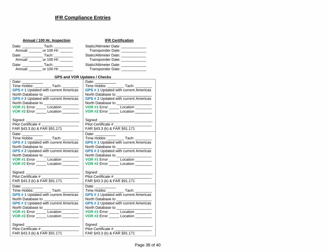
IFR Compliance Entries
Annual / 100 Hr. Inspection IFR Certification
Date: __________ Tach: _________ Annual: ______ or 100 Hr: ______
Static/Altimeter Date: ____________ Transponder Date: ____________
Date: __________ Tach: _________ Annual: ______ or 100 Hr: ______
Static/Altimeter Date: ____________ Transponder Date: ____________
Date: __________ Tach: _________ Annual: ______ or 100 Hr: ______
Static/Altimeter Date: ____________ Transponder Date: ____________
GPS and VOR Updates / Checks
Date: __________ Time Hobbs: ________ Tach: ________ GPS # 1 Updated with current Americas
North Database to _________________ GPS # 2 Updated with current Americas
North Database to _________________ VOR #1 Error _____ Location ________ VOR #2 Error _____ Location ________
Signed: __________________________ Pilot Certificate # __________________ FAR §43.3 (k) & FAR §91.171
Page 39 of 40
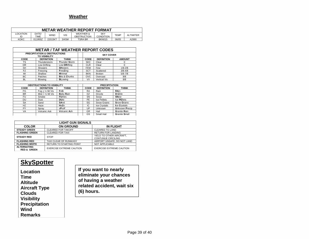
Weather
METAR WEATHER REPORT FORMAT LOCATION
ID DATE/ TIME
WIND VIS WEATHER &
OBSTRUCTION SKY
CONDITION TEMP ALTIMITER
KOKC 011955Z 22015KT 3/4SM TSRA BR BKN015 06/05 A2990
METAR / TAF WEATHER REPORT CODES PRECIPITATION & OBSTRUCTIONS
TO VISIBILITY
SKY COVER
CODE DEFINITION THINK CODE DEFINITION AMOUNT
TS Thunderstorm Thunder Storm SKC Clear 0
DR Low Drifting Low DRifting CLR Clear 0
SH Showers SHowers FEW Few 1/8-2/8
FZ Freezing FreeZing SCT Scattered 3/8-4/8
MI Shallow Minimal BKN Broken 5/8-7/8
BC Patches Bits & Chunks OVC Overcast 8/8
BL Blowing BLowing VV Vertical Vis 8/8
OBSTRUCTIONS TO VISIBILITY PRECIPITATION
CODE DEFINITION THINK CODE DEFINITION THINK
FG Fog < ½ Mi Vis FoG RA Rain RAin
BR Mist > ½ Mi Vis Baby Rain DZ Drizzle DriZzle
FU Smoke FUmes SN Snow SNow
DU Dust DUst PE Ice Pellets Ice PEllets
SA Sand SAnd SG Snow Grains Snow Grains
HZ Haze HaZe IC Ice Crystals Ice Crystals
PY Spray sPraY UP Unknown Unknown Precip
VA Volcanic Ask Volcanic Ash GR Hail Granite Rain
GS Small Hail Granite Small
LIGHT GUN SIGNALS
COLOR ON GROUND IN FLIGHT STEADY GREEN CLEARED FOR TAKOFF CLEARED TO LAND
FLASHING GREEN CLEARED FOR TAXI RETURN FOR LANDING
STEADY RED STOP YIELD TO OTHER AIRCRAFT, CONTUNUE CIRCILING
FLASHING RED TAXI CLEAR OF RUNWASY AIRPORT UNSAFE, DO NOT LAND
FLASHING WHITE RETURN TO STARTING POINT NOT APPLICABLE
ALTERNATING RED & GREEN
EXERCISE EXTREME CAUTION EXERCISE EXTREME CAUTION
SkySpotter
Location Time Altitude Aircraft Type Clouds Visibility Precipitation Wind Remarks
If you want to nearly eliminate your chances of having a weather related accident, wait six
(6) hours.
Page 40 of 40
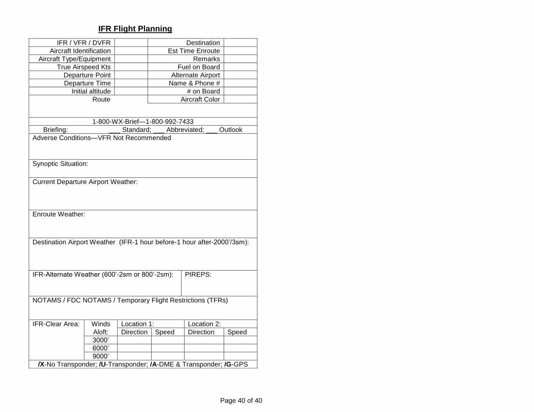
IFR Flight Planning
IFR / VFR / DVFR Destination
Aircraft Identification Est Time Enroute
Aircraft Type/Equipment Remarks
True Airspeed Kts Fuel on Board
Departure Point Alternate Airport
Departure Time Name & Phone #
Initial altitude # on Board
Route Aircraft Color
1-800-WX-Brief—1-800-992-7433
Briefing: ___ Standard; ___ Abbreviated; ___ Outlook
Adverse Conditions—VFR Not Recommended
Synoptic Situation:
Current Departure Airport Weather:
Enroute Weather:
Destination Airport Weather (IFR-1 hour before-1 hour after-2000’/3sm):
IFR-Alternate Weather (600’-2sm or 800’-2sm): PIREPS:
NOTAMS / FDC NOTAMS / Temporary Flight Restrictions (TFRs)
IFR-Clear Area: Winds Location 1: Location 2:
Aloft: Direction Speed Direction Speed
3000’
6000’
9000’
/X-No Transponder; /U-Transponder; /A-DME & Transponder; /G-GPS