PART 3 - Texas A&M University€¦ · Web viewPART 3. Markings. TABLE ... Section 3B.22...
49
PART 3. MARKINGS TABLE OF CONTENTS Page CHAPTER 3A. GENERAL Section 3A.01 Functions and Limitations...............................3A-1 Section 3A.02 Standardization of Application..........................3A-1 Section 3A.03 Materials...............................................3A-1 Section 3A.04 Colors..................................................3A-1 Section 3A.05 Widths and Patterns of Longitudinal Pavement Markings...3A-2 CHAPTER 3B. PAVEMENT AND CURB MARKINGS Section 3B.01 Yellow Centerline Pavement Markings and Warrants........3B-1 Section 3B.02 No-Passing Zone Pavement Markings and Warrants..........3B-1 Section 3B.03 Other Yellow Longitudinal Pavement Markings.............3B-5 Section 3B.04 White Lane Line Pavement Markings and Warrants..........3B-7 Section 3B.05 Other White Longitudinal Pavement Markings.............3B-11 Section 3B.06 Edge Line Pavement Markings............................3B-16 Section 3B.07 Warrants for Use of Edge Lines.........................3B-16 Section 3B.08 Extensions Through Intersections or Interchanges.......3B-16 Section 3B.09 Lane Reduction Transition Markings.....................3B-19 Section 3B.10 Approach Markings for Obstructions.....................3B-19 Section 3B.11 Raised Pavement Markers................................3B-23 Section 3B.12 Raised Pavement Markers as Vehicle Positioning Guides with Other Longitudinal Markings..................................................3B-24 Section 3B.13 Raised Pavement Markers Supplementing Other Markings...3B-24 Section 3B.14 Raised Pavement Markers Substituting for Pavement Markings3B-24 Section 3B.15 Transverse Markings....................................3B-25 Section 3B.16 Stop and Yield Lines...................................3B-25 Section 3B.17 Crosswalk Markings.....................................3B-27 Section 3B.18 Parking Space Markings.................................3B-28 Section 3B.19 Pavement Word and Symbol Markings......................3B-28 Section 3B.20 Speed Measurement Markings.............................3B-38 Section 3B.21 Curb Markings..........................................3B-38 Section 3B.22 Preferential Lane Word and Symbol Markings.............3B-39 Section 3B.23 Preferential Lane Longitudinal Markings for Motor Vehicles3B-40 Section 3B.24 Markings for Roundabout Intersections..................3B-44 Section 3B.25 Markings for Other Circular Intersections..............3B-44 Section 3B.26 Speed Hump Markings....................................3B-44 Section 3B.27 Advance Speed Hump Markings............................3B-44 CHAPTER 3C. OBJECT MARKERS Section 3C.01 Object Marker Design and Placement Height...............3C-1 Section 3C.02 Markings for Objects in the Roadway.....................3C-1 Section 3C.03 Markings for Objects Adjacent to the Roadway............3C-3 Section 3C.04 End-of-Roadway Markers..................................3C-3
Transcript of PART 3 - Texas A&M University€¦ · Web viewPART 3. Markings. TABLE ... Section 3B.22...
PART 3. MARKINGS
TABLE OF CONTENTS
Page
CHAPTER 3A. GENERAL
Section 3A.01 Functions and Limitations.............................................................................................3A-1Section 3A.02 Standardization of Application......................................................................................3A-1Section 3A.03 Materials........................................................................................................................3A-1Section 3A.04 Colors.............................................................................................................................3A-1Section 3A.05 Widths and Patterns of Longitudinal Pavement Markings............................................3A-2
CHAPTER 3B. PAVEMENT AND CURB MARKINGS
Section 3B.01 Yellow Centerline Pavement Markings and Warrants...................................................3B-1Section 3B.02 No-Passing Zone Pavement Markings and Warrants....................................................3B-1Section 3B.03 Other Yellow Longitudinal Pavement Markings...........................................................3B-5Section 3B.04 White Lane Line Pavement Markings and Warrants.....................................................3B-7Section 3B.05 Other White Longitudinal Pavement Markings...........................................................3B-11Section 3B.06 Edge Line Pavement Markings....................................................................................3B-16Section 3B.07 Warrants for Use of Edge Lines...................................................................................3B-16Section 3B.08 Extensions Through Intersections or Interchanges......................................................3B-16Section 3B.09 Lane Reduction Transition Markings..........................................................................3B-19Section 3B.10 Approach Markings for Obstructions..........................................................................3B-19Section 3B.11 Raised Pavement Markers............................................................................................3B-23Section 3B.12 Raised Pavement Markers as Vehicle Positioning Guides with Other Longitudinal Markings
3B-24Section 3B.13 Raised Pavement Markers Supplementing Other Markings........................................3B-24Section 3B.14 Raised Pavement Markers Substituting for Pavement Markings................................3B-24Section 3B.15 Transverse Markings....................................................................................................3B-25Section 3B.16 Stop and Yield Lines....................................................................................................3B-25Section 3B.17 Crosswalk Markings....................................................................................................3B-27Section 3B.18 Parking Space Markings..............................................................................................3B-28Section 3B.19 Pavement Word and Symbol Markings.......................................................................3B-28Section 3B.20 Speed Measurement Markings.....................................................................................3B-38Section 3B.21 Curb Markings.............................................................................................................3B-38Section 3B.22 Preferential Lane Word and Symbol Markings...........................................................3B-39Section 3B.23 Preferential Lane Longitudinal Markings for Motor Vehicles....................................3B-40Section 3B.24 Markings for Roundabout Intersections.......................................................................3B-44Section 3B.25 Markings for Other Circular Intersections...................................................................3B-44Section 3B.26 Speed Hump Markings................................................................................................3B-44Section 3B.27 Advance Speed Hump Markings.................................................................................3B-44
CHAPTER 3C. OBJECT MARKERS
Section 3C.01 Object Marker Design and Placement Height...............................................................3C-1Section 3C.02 Markings for Objects in the Roadway...........................................................................3C-1Section 3C.03 Markings for Objects Adjacent to the Roadway............................................................3C-3Section 3C.04 End-of-Roadway Markers..............................................................................................3C-3
CHAPTER 3D. DELINEATORS
Section 3D.01 Delineators.....................................................................................................................3D-1Section 3D.02 Delineator Design..........................................................................................................3D-1Section 3D.03 Delineator Application...................................................................................................3D-1Section 3D.04 Delineator Placement and Spacing................................................................................3D-2
CHAPTER 3E. COLORED PAVEMENTS
Section 3E.01 General...........................................................................................................................3E-1
CHAPTER 3F. BARRICADES AND CHANNELIZING DEVICES
Section 3F.01 Barricades.......................................................................................................................3F-1Section 3F.02 Channelizing Devices.....................................................................................................3F-1
CHAPTER 3G. ISLANDS
Section 3G.01 General...........................................................................................................................3G-1Section 3G.02 Approach-End Treatment..............................................................................................3G-1Section 3G.03 Island Marking Application...........................................................................................3G-1Section 3G.04 Island Marking Colors...................................................................................................3G-1Section 3G.05 Island Object Markers....................................................................................................3G-2Section 3G.06 Island Delineators..........................................................................................................3G-2
FIGURES
CHAPTER 3B. PAVEMENT AND CURB MARKINGSFigure 3B-1 Examples of Two-Lane, Two-Way Marking Applications...........................................3B-2Figure 3B-2 Examples of Four-or-More Lane, Two-Way Marking Applications.............................3B-3Figure 3B-3 Examples of Three-Lane, Two-Way Marking Applications.........................................3B-4Figure 3B-4 Example of Three-Lane, Two-Way Marking for Changing Direction of the Center Lane3B-6Figure 3B-5 Method of Locating and Determining the Limits of No-Passing Zones at Curves.......3B-8Figure 3B-6 Example of Reversible Lane Marking Application.......................................................3B-9Figure 3B-7 Example of Two-Way Left-Turn Lane Marking Applications....................................3B-10Figure 3B-8 Examples of Channelizing Line Applications for Exit Ramp Markings.....................3B-12Figure 3B-9 Examples of Channelizing Line Applications for Entrance Ramp Markings..............3B-14Figure 3B-10 Example of Lane Drop Markings at Exit Ramps.........................................................3B-15Figure 3B-11 Examples of Extensions through Intersections............................................................3B-17Figure 3B-12 Examples of Lane Reduction Markings.......................................................................3B-20Figure 3B-13 Examples of Markings for Obstructions in the Roadway............................................3B-21Figure 3B-14 Examples of Yield Line Layouts.................................................................................3B-26Figure 3B-15 Examples of Yield Lines at Unsignalized Midblock Crosswalks................................3B-27Figure 3B-16 Examples of Crosswalk Markings...............................................................................3B-29Figure 3B-17 Example of Crosswalk Markings for Exclusive Pedestrian Phase That Permits
Diagonal Crossing........................................................................................................3B-29Figure 3B-18 Examples of Parking Space Markings.........................................................................3B-30Figure 3B-19 International Symbol of Accessibility Parking Space Marking with Blue Background
and White Border Options...........................................................................................3B-31Figure 3B-20 Example of Elongated Letters for Word Pavement Markings.....................................3B-31Figure 3B-21 Examples of Standard Arrows for Pavement Markings..............................................3B-32Figure 3B-22 Examples of Lane Use Control Word and Symbol Markings.....................................3B-34Figure 3B-23 Examples of Arrow Markings at Exit Ramp Terminals..............................................3B-35Figure 3B-24 Examples of Arrow Markings at Entrance Ramp Terminals.......................................3B-36Figure 3B-25 Yield Ahead Triangle Symbols....................................................................................3B-37Figure 3B-26 Examples of Markings for Preferential Lanes.............................................................3B-42Figure 3B-27 Examples of Markings for Roundabout Intersections with One-Lane Approaches....3B-45Figure 3B-28 Examples of Markings for Roundabout Intersections with Two-Lane Approaches....3B-46Figure 3B-29 Examples of Pavement Markings for Speed Humps Without Crosswalks..................3B-47Figure 3B-30 Examples of Pavement Markings for Speed Tables or Speed Humps with Crosswalks3B-48Figure 3B-31 Examples of Advance Warning Markings for Speed Humps......................................3B-49
CHAPTER 3C OBJECT MARKERS
Figure 3C-1 Object Markers and End-of-Roadway Markers.............................................................3C-2
CHAPTER 3D. DELINEATORS
Figure 3D-1 Example of Delineator Installation................................................................................3D-3
TABLES
CHAPTER 3B. PAVEMENT AND CURB MARKINGS
Table 3B-1 Minimum Passing Sight Distances................................................................................3B-7Table 3B-2 Standard Edge Line Lane Markings for Preferential Lanes.........................................3B-41
CHAPTER 3D. DELINEATORS
Table 3D-1 Approximate Spacing for Delineators on Horizontal Curves........................................3D-4
CHAPTER 3A. GENERAL
Section 3A.01 Functions and LimitationsSupport:
Markings on highways have important functions in providing guidance and information for the road user. Major marking types include pavement and curb markings, object markers, delineators, colored pavements, barricades, channelizing devices and islands. In some cases, markings are used to supplement other traffic control devices such as signs, signals and other markings. In other instances, markings are used alone to effectively convey regulations, guidance, or warnings in ways not obtainable by the use of other devices.
Markings have limitations. Visibility of the markings can be limited by snow, debris, and water on or adjacent to the markings. Marking durability is affected by material characteristics, traffic volumes, weather, and location. However, under most highway conditions, markings provide important information while allowing minimal diversion of attention from the roadway.
Pavement markings can enhance roadway delineation with the addition of audible and tactile features such as bars, differential surface profiles, raised pavement markers, or other devices intended to alert the road user that a delineation on the roadway is being traversed.
The general functions of longitudinal lines are:A. A double line indicates maximum or special restrictions,B. A solid line discourages or prohibits crossing (depending on the specific application),C. A broken line indicates a permissive condition, andD. A dotted line provides guidance.
Section 3A.02 Standardization of ApplicationStandard:
Each standard marking shall be used only to convey the meaning prescribed for that marking in this Manual. When used for applications not described herein, markings shall conform in all respects to the principles and standards set forth herein.Guidance:
Before any new highway, paved detour, or temporary route is opened to traffic, all necessary markings should be in place.Standard:
Markings that are no longer applicable for roadway conditions or restrictions and that might cause confusion for the road user shall be removed or obliterated to be unidentifiable as a marking as soon as practical. Markings that must be visible at night shall be retroreflective unless ambient illumination assures that the markings are adequately visible. All markings on Interstate highways shall be retroreflective.Option:
Markings may be temporarily masked with tape until they can be removed or obliterated.
Section 3A.03 MaterialsSupport:
Pavement and curb markings are commonly placed by using paints or thermoplastics; however, other suitable marking materials, including raised pavement markers and colored pavements, are also used. Delineators, object markers, barricades, and channelizing devices are visibly placed in a vertical position similar to signs above the roadway.Guidance:
The materials used for markings should provide the specified color throughout their useful life.
Consideration should be given to selecting pavement marking materials that will minimize tripping or loss of traction for pedestrians and bicyclists.
Object markers and delineators should not present a vertical or horizontal clearance obstacle for pedestrians.
Section 3A.04 ColorsStandard:
Markings shall be yellow, white, red, or blue. The colors for markings shall conform to the standard highway colors. Black in conjunction with one of the above colors shall be a usable color.
When used, white markings for longitudinal lines shall delineate:A. The separation of traffic flows in the same direction.B. The right edge of the roadway.
When used, yellow markings for longitudinal lines shall delineate:A. The separation of traffic traveling in opposite directions.B. The left edge of the roadways of divided and one-way highways and ramps.C. The separation of two-way left turn lanes and reversible lanes from other lanes.
When used, red raised pavement markers shall delineate roadways that shall not be entered or used.
When used, blue markings shall supplement white markings for parking spaces for persons with disabilities. When used, blue raised pavement markers shall indicate locations of fire hydrants along a roadway.Option:
Black may be used in combination with the above colors where a light-colored pavement does not provide sufficient contrast with the markings.Support:
When used in combination with other colors, black is not considered a marking color, but only a contrast-enhancing system for the markings.
Section 3A.05 Widths and Patterns of Longitudinal Pavement MarkingsStandard:
The widths and patterns of longitudinal lines shall be as follows:A. A normal line is 100 to 150 mm (4 to 6 in) wide.B. A wide line is at least twice the width of a normal line. The width of the line indicates the
degree of emphasis.C. A double line consists of two parallel lines separated by a discernible space.D. A broken line consists of normal line segments separated by gaps.E. A dotted line shall consist of noticeably shorter line segments separated by shorter gaps
than used for a broken line. The width of a dotted line shall be at least the same as the width of the line it extends.
Guidance:Broken lines should consist of 3 m (10 ft) line segments and 9 m (30 ft) gaps, or dimensions in a
similar ratio of line segments to gaps as appropriate for traffic speeds and need for delineation.Option:
A dotted line for line extensions may consist of 0.6 m (2 ft) line segments and 0.6 m (2 ft) to 1.8 m (6 ft) gaps. A dotted line for lane drop/add markings may consist of 0.9 m (3 ft) line segments and 2.7 m (9 ft) gaps.
CHAPTER 3B. PAVEMENT AND CURB MARKINGS
Section 3B.01 Yellow Centerline Pavement Markings and WarrantsStandard:
Centerline pavement markings, when used, shall be the pavement markings used to delineate the separation of traffic lanes that have opposite directions of travel on a roadway and shall be yellow.Option:
Centerline pavement markings may be placed at a location that is not the geometric center of the roadway.
On roadways without continuous centerline pavement markings, short sections may be marked with centerline pavement markings to control the position of traffic at specific locations, such as around curves, over hills, on approaches to highway-railroad grade crossings, at highway-railroad grade crossings, and at bridges.Standard:
The centerline markings on two-lane, two-way roadways shall be one of the following as shown in Figure 3B-1:
A. Two-direction passing zone markings consisting of a normal broken yellow line where crossing the centerline markings for passing with care is permitted for traffic traveling in either direction;
B. One-direction no-passing zone markings consisting of a normal broken yellow line and a normal solid yellow line where crossing the centerline markings for passing with care is permitted for the traffic traveling adjacent to the broken line, but is prohibited for traffic traveling adjacent to the solid line; and
C. Two-direction no-passing zone markings consisting of two normal solid yellow lines where crossing the centerline markings for passing is prohibited for traffic traveling in either direction.
The centerline markings on undivided two-way roadways with four or more lanes for moving motor vehicle traffic always available shall be the two-direction no-passing zone markings consisting of two normal solid yellow lines as shown in Figure 3B-2.Guidance:
On two-way roadways with three through lanes for moving motor vehicle traffic, two lanes should be designated for traffic in one direction by using one- or two-direction no-passing zone markings as shown in Figure 3B-3.Standard:
Centerline markings shall be placed on all paved urban arterials and collectors that have a traveled way of 6.1 m (20 ft) or more in width and an ADT of 6,000 vehicles per day or greater. Centerline markings shall also be placed on all paved two-way streets or highways that have three or more lanes for moving motor vehicle traffic.Guidance:
Centerline markings should be placed on paved urban arterials and collectors that have a traveled way of 6.1 m (20 ft) or more in width and an ADT of 4,000 vehicles per day or greater. Centerline markings should also be placed on all rural arterials and collectors that have a traveled way of 5.5 m (18 ft) or more in width and an ADT of 3,000 vehicles per day or greater. Centerline markings should also be placed on other traveled ways where an engineering study indicates such a need.
Engineering judgment should be used in determining whether to place centerline markings on traveled ways that are less than 4.9 m (16 ft) wide because of the potential for traffic encroaching on the
pavement edges, traffic being affected by parked vehicles, and traffic encroaching into the opposing traffic lane.Option:
Centerline markings may be placed on other paved two-way traveled ways that are 4.9 m (16 ft) or more in width.
If a traffic count is not available, the ADTs described in this Section may be estimates that are based on engineering judgment.
Section 3B.02 No-Passing Zone Pavement Markings and WarrantsStandard:
No-passing zones shall be marked by either the one direction no-passing zone pavement markings or the two-direction no-passing zone pavement markings described previously and shown in Figures 3B-1 and 3B-3.
When centerline markings are used, no-passing zone markings shall be used on two-way roadways at lane reduction transitions (see Section 3B.09) and on approaches to obstructions that must be passed on the right (see Section 3B.10).Guidance:
Where the distance between successive no-passing zones is less than 120 m (400 ft), no-passing markings should connect the zones.Standard:
Where centerline markings are used, no-passing zone markings shall be used on approaches to highway-rail grade crossings in conformance with Section 8B.20.Option:
In addition to pavement markings, no-passing zone signs (see Sections 2B.29, 2B.30, and 2C.35) may be used to emphasize the existence and extent of a no-passing zone.Support:
Section 11-307 of the “Uniform Vehicle Code (UVC) Revised” contains further information regarding no-passing zones. The “UVC” can be obtained from the National Committee on Uniform Traffic Laws and Ordinances at the address shown on Page i.Standard:
On two-way, two- or three-lane roadways where centerline markings are installed, no-passing zones shall be established at vertical and horizontal curves and other locations where an engineering study indicates that passing must be prohibited because of inadequate sight distances or other special conditions.
On three-lane roadways where the direction of travel in the center lane transitions from one direction to the other, a no-passing buffer zone shall be provided in the center lane as shown in Figure 3B-4. A lane transition shall be provided at each end of the buffer zone.
The buffer zone shall be a median island that is at least 15 m (50 ft) in length.Guidance:
For three-lane roadways having a posted or statutory speed limit of 70 km/h (45 mph) or greater, the lane transition taper length should be computed by the formula L = 0.62 WS for speeds in km/h (L = WS for speeds in mph). For roadways where the posted or statutory speed limit is less than 70 km/h (45 mph), the formula L = WS2/155 for speeds in km/h (L = WS2/60 for speeds in mph) should be used to compute taper length. Under both formulas, L equals the taper length in meters (feet), W equals the width of the center lane or
offset distance in meters (feet), and S equals the 85th-percentile speed or the posted or statutory speed limit, whichever is higher.Standard:
The minimum lane transition taper length shall be 30 m (100 ft) in urban areas and 60 m (200 ft) in rural areas.
On roadways with centerline markings, no-passing zone markings shall be used at horizontal or vertical curves where the passing sight distance is less than the minimum necessary for reasonably safe passing at the 85th-percentile speed or the posted or statutory speed limit as shown in Table 3B-1. The passing sight distance on a vertical curve is the distance at which an object 1.07 m (3.5 ft) above the pavement surface can be seen from a point 1.07 m (3.5 ft) above the pavement (see Figure 3B-5). Similarly, the passing sight distance on a horizontal curve is the distance measured along the centerline (or right-hand lane line of a three-lane roadway) between two points 1.07 m (3.5 ft) above the pavement on a line tangent to the embankment or other obstruction that cuts off the view on the inside of the curve (see Figure 3B-5).Support:
The beginning of a no-passing zone at point “a” in Figure 3B-5 is that point where the sight distance first becomes less than that specified in Table 3B-1. The end of the no-passing zone at point “b” in Figure 3B-5 is that point at which the sight distance again becomes greater than the minimum specified.
Section 3B.03 Other Yellow Longitudinal Pavement MarkingsStandard:
If reversible lanes are used, the lane line pavement markings on each side of reversible lanes shall consist of a normal double broken yellow line to delineate the edge of a lane in which the direction of travel is reversed from time to time, such that each of these markings serve as the centerline markings of the roadway during some period (see Figure 3B-6).
Signs (see Section 2B.25), lane-use control signals (see Chapter 4J), or both shall be used to supplement reversible lane pavement markings.
If a two-way left-turn lane that is never operated as a reversible lane is used, the lane line pavement markings on each side of the two-way left-turn lane shall consist of a normal broken yellow line and a normal solid yellow line to delineate the edges of a lane that can be used by traffic in either direction as part of a left-turn maneuver. These markings shall be placed with the broken line toward the two-way left-turn lane and the solid line toward the adjacent traffic lane as shown in Figure 3B-7.Option:
Pavement marking arrows may be used in conjunction with the two-way left-turn lane markings as shown in Figure 3B-7.Guidance:
Signs should be used in conjunction with the two-way left turn markings (see Section 2B.24).Standard:
If a continuous median island formed by pavement markings separating travel in opposite directions is used, two sets of double solid yellow lines shall be used to form the island as shown in Figures 3B-2 and 3B-4. Other markings in the median island area shall also be yellow, except crosswalk markings which shall be white (see Section 3B.17).
Section 3B.04 White Lane Line Pavement Markings and WarrantsStandard:
When used, lane line pavement markings delineating the separation of traffic lanes that have the same direction of travel shall be white.Support:
Examples of lane line markings are shown in Figures 3B-2, 3B-3, 3B-7 through 3B-13, 3B-22, 3B-24, and 3B-26.Standard:
Where crossing the lane line markings with care is permitted, the lane line markings shall consist of a normal broken white line.
Where crossing the lane line markings is discouraged, the lane line markings shall consist of a normal solid white line.Option:
Solid white lane line markings may be used to separate through traffic lanes from auxiliary lanes, such as uphill truck lanes, left- or right-turn lanes, and preferential lanes. They may also be used to separate traffic lanes approaching an intersection.
Wide solid lane line markings may be used for greater emphasis.Standard:
Where crossing the lane line markings is prohibited, the lane line markings shall consist of two normal solid white lines.
Lane line markings shall be used on all freeways and Interstate highways.Guidance:
Lane line markings should be used on all roadways with two or more adjacent traffic lanes that have the same direction of travel. Lane line markings should also be used at congested locations where the roadway will accommodate more traffic lanes with lane line markings than without the markings.
Section 3B.05 Other White Longitudinal Pavement MarkingsStandard:
A channelizing line shall be a wide or double solid white line.Option:
Channelizing lines may be used to form channelizing islands where traffic traveling in the same direction is permitted on both sides of the island.Standard:
Other pavement markings in the channelizing island area shall be white.Support:
Examples of channelizing line applications are shown in Figures 3B-8, 3B-9, and 3B-13.Channelizing lines at exit ramps as shown in Figure 3B-8 define the neutral area, direct exiting traffic
at the proper angle for smooth divergence from the main lanes into the ramp, and reduce the probability of colliding with objects adjacent to the roadway.
Channelizing lines at entrance ramps as shown in Figure 3B-9 promote reasonably safe and efficient merging with the through traffic.Standard:
For exit ramps, channelizing lines shall be placed along the sides of the neutral area adjacent to the through traffic lane and the ramp lane. With a parallel deceleration lane, a lane line shall be extended from the beginning of the channelizing line upstream for a distance of one-half the length of the full-width deceleration lane as shown in Figure 3B-8.
Option:White chevron markings may be placed in the neutral area for special emphasis as shown in Figure
3B-8.Guidance:
For entrance ramps, a channelizing line should be placed along the side of the neutral area adjacent to the ramp lane.
For entrance ramps with a parallel acceleration lane, a lane line should be extended from the end of the channelizing line for a distance of one-half the length of the full-width acceleration lane as shown in Figure 3B-9.Option:
For entrance ramps with a tapered acceleration lane, lane line markings may be placed to extend the channelizing line, but not beyond a point where the tapered lane meets the near side of the through traffic lane as shown in Figure 3B-9.
Lane drop markings as shown in Figure 3B-10 may be used in advance of lane drops at exit ramps to distinguish a lane drop from a normal exit ramp or from an auxiliary lane. The lane drop marking may consist of a wide, white dotted line with line segments 0.9 m (3 ft) in length separated by 2.7 m (9 ft) gaps.Guidance:
If used, lane drop markings should begin 800 m (0.5 mi) in advance of the theoretical gore point.Option:
Where lane changes might cause conflicts, a wide solid white channelizing line may extend upstream from the theoretical gore point.
Section 3B.06 Edge Line Pavement MarkingsStandard:
If used, edge line pavement markings shall delineate the right or left edges of a roadway.Except for dotted edge line extensions (see Section 3B.08), edge line markings shall not be
continued through intersections or major driveways.If used on the roadways of divided highways or one-way streets, or on any ramp in the direction
of travel, left edge line pavement markings shall consist of a normal solid yellow line to delineate the left edge of a roadway or to indicate driving or passing restrictions left of these markings.
If used, the right edge line pavement markings shall consist of a normal solid white line to delineate the right edge of the roadway.Guidance:
Edge line markings should not be broken for minor driveways.Support:
Edge line markings have unique value as visual references to guide road users during adverse weather and visibility conditions.Option:
Wide solid edge line markings may be used for greater emphasis.
Section 3B.07 Warrants for Use of Edge LinesStandard:
Edge line markings shall be placed on paved streets or highways with the following characteristics:
A. Freeways;B. Expressways; andC. Rural arterials with a traveled way of 6.1 m (20 ft) or more in width and an ADT of 6,000
vehicles per day or greater.
Guidance:Edge line markings should be placed on paved streets or highways with the following characteristics:A. Rural arterials and collectors with a traveled way of 6.1 m (20 ft) or more in width and an ADT of
3,000 vehicles per day or greater.B. At other paved streets and highways where an engineering study indicates a need for edge line
markings.Edge line markings should not be placed where an engineering study or engineering judgment
indicates that providing them is likely to decrease safety.Option:
Edge line markings may be placed on streets and highways with or without centerline markings.Edge line markings may be excluded, based on engineering judgment, for reasons such as if the
traveled way edges are delineated by curbs, parking, bicycle lanes, or other markings.Edge line markings may be used where edge delineation is desirable to minimize unnecessary driving
on paved shoulders or on refuge areas that have lesser structural pavement strength than the adjacent roadway.
Section 3B.08 Extensions Through Intersections or InterchangesStandard:
Pavement markings extended into or continued through an intersection or interchange area shall be the same color and at least the same width as the line markings they extend (see Figure 3B-11).Option:
A normal line may be used to extend a wide line through an intersection.Guidance:
Where highway design or reduced visibility conditions make it desirable to provide control or to guide vehicles through an intersection or interchange, such as at offset, skewed, complex, or multilegged intersections, on curved roadways, or where multiple turn lanes are used, dotted line markings should be used to extend longitudinal line markings through an intersection or interchange area.Option:
Dotted edge line extensions may be placed through intersections or major driveways.Guidance:
Where greater restriction is required, solid lane lines or channelizing lines should be extended into or continued through intersections or major driveways. However, edge lines should not be extended into or continued through intersections or major driveways as solid lines.
A single line of equal width to one of the lines of the double line should be used to extend a double line through an intersection.
To the extent possible, pavement marking extensions through intersections should be designed in a manner that minimizes potential confusion for drivers in adjacent or opposing lanes.
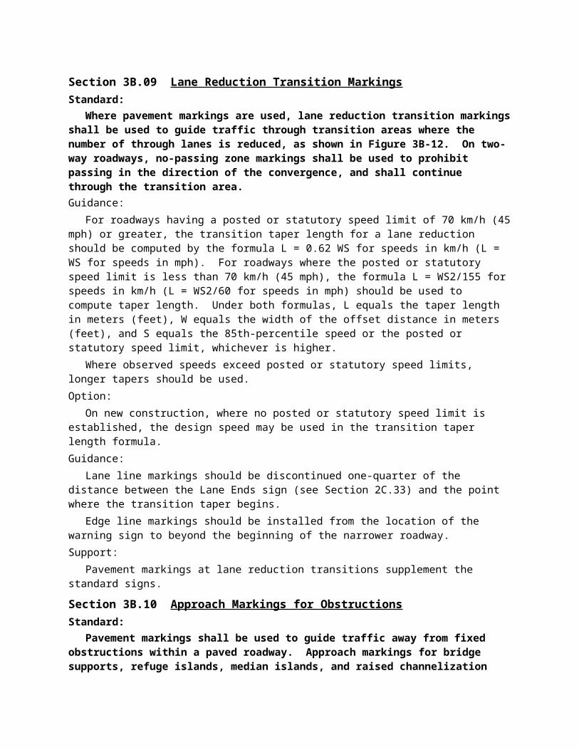
Section 3B.09 Lane Reduction Transition MarkingsStandard:
Where pavement markings are used, lane reduction transition markings shall be used to guide traffic through transition areas where the number of through lanes is reduced, as shown in Figure 3B-12. On two-way roadways, no-passing zone markings shall be used to prohibit passing in the direction of the convergence, and shall continue through the transition area.Guidance:
For roadways having a posted or statutory speed limit of 70 km/h (45 mph) or greater, the transition taper length for a lane reduction should be computed by the formula L = 0.62 WS for speeds in km/h (L = WS for speeds in mph). For roadways where the posted or statutory speed limit is less than 70 km/h (45 mph), the formula L = WS2/155 for speeds in km/h (L = WS2/60 for speeds in mph) should be used to compute taper length. Under both formulas, L equals the taper length in meters (feet), W equals the width of the offset distance in meters (feet), and S equals the 85th-percentile speed or the posted or statutory speed limit, whichever is higher.
Where observed speeds exceed posted or statutory speed limits, longer tapers should be used.Option:
On new construction, where no posted or statutory speed limit is established, the design speed may be used in the transition taper length formula.Guidance:
Lane line markings should be discontinued one-quarter of the distance between the Lane Ends sign (see Section 2C.33) and the point where the transition taper begins.
Edge line markings should be installed from the location of the warning sign to beyond the beginning of the narrower roadway.Support:
Pavement markings at lane reduction transitions supplement the standard signs.
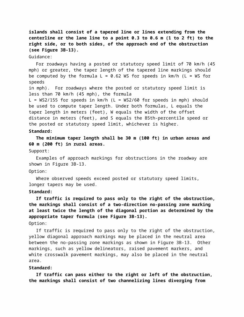
Section 3B.10 Approach Markings for ObstructionsStandard:
Pavement markings shall be used to guide traffic away from fixed obstructions within a paved roadway. Approach markings for bridge supports, refuge islands, median islands, and raised channelization islands shall consist of a tapered line or lines extending from the centerline or the lane line to a point 0.3 to 0.6 m (1 to 2 ft) to the right side, or to both sides, of the approach end of the obstruction (see Figure 3B-13).Guidance:
For roadways having a posted or statutory speed limit of 70 km/h (45 mph) or greater, the taper length of the tapered line markings should be computed by the formula L = 0.62 WS for speeds in km/h (L = WS for speeds in mph). For roadways where the posted or statutory speed limit is less than 70 km/h (45 mph), the formula L = WS2/155 for speeds in km/h (L = WS2/60 for speeds in mph) should be used to compute taper length. Under both formulas, L equals the taper length in meters (feet), W equals the width of the offset distance in meters (feet), and S equals the 85th-percentile speed or the posted or statutory speed limit, whichever is higher.Standard:
The minimum taper length shall be 30 m (100 ft) in urban areas and 60 m (200 ft) in rural areas.Support:
Examples of approach markings for obstructions in the roadway are shown in Figure 3B-13.Option:
Where observed speeds exceed posted or statutory speed limits, longer tapers may be used.Standard:
If traffic is required to pass only to the right of the obstruction, the markings shall consist of a two-direction no-passing zone marking at least twice the length of the diagonal portion as determined by the appropriate taper formula (see Figure 3B-13).Option:
If traffic is required to pass only to the right of the obstruction, yellow diagonal approach markings may be placed in the neutral area between the no-passing zone markings as shown in Figure 3B-13. Other markings, such as yellow delineators, raised pavement markers, and white crosswalk pavement markings, may also be placed in the neutral area.Standard:
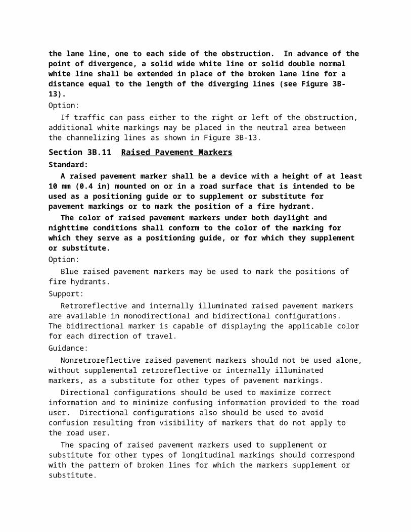
If traffic can pass either to the right or left of the obstruction, the markings shall consist of two channelizing lines diverging from the lane line, one to each side of the obstruction. In advance of the point of divergence, a solid wide white line or solid double normal white line shall be extended in place of the broken lane line for a distance equal to the length of the diverging lines (see Figure 3B-13).Option:
If traffic can pass either to the right or left of the obstruction, additional white markings may be placed in the neutral area between the channelizing lines as shown in Figure 3B-13.
Section 3B.11 Raised Pavement MarkersStandard:
A raised pavement marker shall be a device with a height of at least 10 mm (0.4 in) mounted on or in a road surface that is intended to be used as a positioning guide or to supplement or substitute for pavement markings or to mark the position of a fire hydrant.
The color of raised pavement markers under both daylight and nighttime conditions shall conform to the color of the marking for which they serve as a positioning guide, or for which they supplement or substitute.Option:
Blue raised pavement markers may be used to mark the positions of fire hydrants.Support:
Retroreflective and internally illuminated raised pavement markers are available in monodirectional and bidirectional configurations. The bidirectional marker is capable of displaying the applicable color for each direction of travel.Guidance:
Nonretroreflective raised pavement markers should not be used alone, without supplemental retroreflective or internally illuminated markers, as a substitute for other types of pavement markings.
Directional configurations should be used to maximize correct information and to minimize confusing information provided to the road user. Directional configurations also should be used to avoid confusion resulting from visibility of markers that do not apply to the road user.
The spacing of raised pavement markers used to supplement or substitute for other types of longitudinal markings should correspond with the pattern of broken lines for which the markers supplement or substitute.
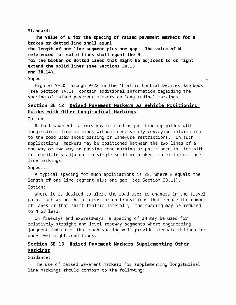
Standard: The value of N for the spacing of raised pavement markers for a broken or dotted line shall
equal the length of one line segment plus one gap. The value of N referenced for solid lines shall equal the N for the broken or dotted lines that might be adjacent to or might extend the solid lines (see Sections 3B.13 and 3B.14).Support:
Figures 9-20 through 9-22 in the “Traffic Control Devices Handbook” (see Section 1A.11) contain additional information regarding the spacing of raised pavement markers on longitudinal markings.
Section 3B.12 Raised Pavement Markers as Vehicle Positioning Guides with Other Longitudinal MarkingsOption:
Raised pavement markers may be used as positioning guides with longitudinal line markings without necessarily conveying information to the road user about passing or lane-use restrictions. In such applications, markers may be positioned between the two lines of a one-way or two-way no-passing zone marking or positioned in line with or immediately adjacent to single solid or broken centerline or lane line markings.Support:
A typical spacing for such applications is 2N, where N equals the length of one line segment plus one gap (see Section 3B.11).Option:
Where it is desired to alert the road user to changes in the travel path, such as on sharp curves or on transitions that reduce the number of lanes or that shift traffic laterally, the spacing may be reduced to N or less.
On freeways and expressways, a spacing of 3N may be used for relatively straight and level roadway segments where engineering judgment indicates that such spacing will provide adequate delineation under wet night conditions.
Section 3B.13 Raised Pavement Markers Supplementing Other MarkingsGuidance:
The use of raised pavement markers for supplementing longitudinal line markings should conform to the following:
A. Lateral Positioning1. When supplementing double line markings, pairs of raised pavement markers placed laterally in
line with or immediately outside of the two lines should be used.2. When supplementing wide line markings, pairs of raised pavement markers placed laterally
adjacent to each other should be used.B. Longitudinal Spacing1. When supplementing solid line markings, raised pavement markers at a spacing no greater than N
(see Section 3B.11) should be used, except when supplementing left edge line markings, a spacing of no greater than N/2 should be used. Raised markers should not supplement right edge line markings.
2. When supplementing broken line markings, a spacing no greater than 3N should be used. However, when supplementing broken line markings identifying reversible lanes, a spacing of no greater than N should be used.
3. When supplementing dotted line markings, a spacing appropriate for the application should be used.
4. When supplementing longitudinal line markings through at-grade intersections, one raised pavement marker for each short line segment should be used.
5. When supplementing edge line extensions through freeway interchanges, a spacing of no greater than N should be used.
Option:Raised pavement markers also may be used to supplement other markings for channelizing islands or
approaches to obstructions.
Section 3B.14 Raised Pavement Markers Substituting for Pavement MarkingsOption:
Retroreflective or internally illuminated raised pavement markers, or nonretroreflective raised pavement markers supplemented by retroreflective or internally illuminated markers, may be substituted for markings of other types.Guidance:
If used, the pattern and color of the raised pavement markers should simulate the pattern and color of the markings for which they substitute.
The normal spacing of raised pavement markers, when substituting for other markings, should be determined in terms of the standard length of the broken line segment.Option:
The side of a raised pavement marker that is visible to traffic proceeding in the wrong direction may be red.Standard:
If raised pavement markers are used to substitute for broken line markings, a group of three to five markers equally spaced at a distance no greater than N/8 (see Section 3B.11) shall be used. If N is other than 12 m (40 ft), the markers shall be equally spaced over the line segment length (at 1/2 points for 3 markers, at 1/3 points for 4 markers, and at 1/4 points for 5 markers). At least one retroreflective or internally illuminated marker per group shall be used or a retroreflective or internally illuminated marker shall be installed midway in each gap between successive groups of nonretroreflective markers.
When raised pavement markers substitute for solid lane line markings, the markers shall be equally spaced at no greater than N/4, with retroreflective or internally illuminated units at a spacing no greater than N/2.Guidance:
Raised pavement markers should not substitute for right edge line markings.Standard:
When raised pavement markers substitute for dotted lines, they shall be spaced at no greater than N/4, with not less than one raised pavement marker per dotted line. At least one raised marker every N shall be retroreflective or internally illuminated.Option:
When substituting for wide lines, raised pavement markers may be placed laterally adjacent to each other to simulate the width of the line.
Section 3B.15 Transverse MarkingsStandard:
Transverse markings, which include shoulder markings, word and symbol markings, stop lines, yield lines, crosswalk lines, speed measurement markings, speed hump markings, parking space markings, and others, shall be white unless otherwise specified herein.Guidance:
Because of the low approach angle at which pavement markings are viewed, transverse lines should be proportioned to provide visibility equal to that of longitudinal lines.Standard:
Pavement marking letters, numerals, and symbols shall be installed in accordance with the Pavement Markings chapter of the “Standard Highway Signs” book (see Section 1A.11).
Section 3B.16 Stop and Yield LinesStandard:
If used, stop lines shall consist of solid white lines extending across approach lanes to indicate the point at which the stop is intended or required to be made.
If used, yield lines (see Figure 3B-14) shall consist of a row of solid white isosceles triangles pointing toward approaching vehicles extending across approach lanes to indicate the point at which the yield is intended or required to be made.Guidance:
Stop lines should be 300 to 600 mm (12 to 24 in) wide.Stop lines should be used to indicate the point behind which vehicles are required to stop, in
compliance with a STOP (R1-1) sign, traffic control signal, or some other traffic control device, except YIELDsigns.
The individual triangles comprising the yield line should have a base of 300 to 600 mm (12 to 24 in) wide and a height equal to 1.5 times the base. The space between the triangles should be 75 to 300 mm (3 to 12 in).Option:
Yield lines may be used to indicate the point behind which vehicles are required to yield in compliance with a YIELD (R1-2) sign or a Yield Here to Pedestrians (R1-5 or R1-5a) sign.Guidance:
If used, stop and yield lines should be placed a minimum of 1.2 m (4 ft) in advance of the nearest crosswalk line at controlled intersections, except for yield lines at roundabout intersections as provided for in Section 3B.24 and at midblock crosswalks. In the absence of a marked crosswalk, the stop line or yield line should be placed at the desired stopping or yielding point, but should be placed no more than 9 m (30 ft) nor less than 1.2 m (4 ft) from the nearest edge of the intersecting traveled way. Stop lines should be placed to allow sufficient sight distance to all other approaches to an intersection.
If used at an unsignalized midblock crosswalk, yield lines should be placed adjacent to the Yield Here to Pedestrians sign located 6.1 to 15 m (20 to 50 ft) in advance of the nearest crosswalk line, and parking should be prohibited in the area between the yield line and the crosswalk (see Figure 3B-15).
Stop lines at midblock signalized locations should be placed at least 12 m (40 ft) in advance of the nearest signal indication (see Section 4D.15).Support:
Drivers who yield too close to crosswalks on multi-lane approaches place pedestrians at risk by blocking other drivers’ views of pedestrians.
Section 3B.17 Crosswalk MarkingsSupport:
Crosswalk markings provide guidance for pedestrians who are crossing roadways by defining and delineating paths on approaches to and within signalized intersections, and on approaches to other intersections where traffic stops.
Crosswalk markings also serve to alert road users of a pedestrian crossing point across roadways not controlled by highway traffic signals or STOP signs.
At nonintersection locations, crosswalk markings legally establish the crosswalk.Standard:
When crosswalk lines are used, they shall consist of solid white lines that mark the crosswalk. They shall be not less than 150 mm (6 in) nor greater than 600 mm (24 in) in width.Guidance:
If transverse lines are used to mark a crosswalk, the gap between the lines should not be less than 1.8 m (6 ft). If diagonal or longitudinal lines are used without transverse lines to mark a crosswalk, the crosswalk should be not less than 1.8 m (6 ft) wide.
Crosswalk lines, if used on both sides of the crosswalk, should extend across the full width of pavement or to the edge of the intersecting crosswalk to discourage diagonal walking between crosswalks (see Figures 3B-15 and 3B-16).
Crosswalks should be marked at all intersections where there is substantial conflict between vehicular and pedestrian movements.
Marked crosswalks also should be provided at other appropriate points of pedestrian concentration, such as at loading islands, midblock pedestrian crossings, or where pedestrians could not otherwise recognize the proper place to cross.
Crosswalk lines should not be used indiscriminately. An engineering study should be performed before they are installed at locations away from highway traffic signals or STOP signs.
Because nonintersection pedestrian crossings are generally unexpected by the road user, warning signs (see Section 2C.41) should be installed and adequate visibility should be provided by parking prohibitions.Support:
Section 3B.16 contains information regarding placement of stop line markings near crosswalk markings.Option:
For added visibility, the area of the crosswalk may be marked with white diagonal lines at a 45-degree angle to the line of the crosswalk or with white longitudinal lines parallel to traffic flow as shown in Figure 3B-16.
When diagonal or longitudinal lines are used to mark a crosswalk, the transverse crosswalk lines may be omitted. This type of marking may be used at locations where substantial numbers of pedestrians cross without any other traffic control device, at locations where physical conditions are such that added visibility of the crosswalk is desired, or at places where a pedestrian crosswalk might not be expected.Guidance:
If used, the diagonal or longitudinal lines should be 300 to 600 mm (12 to 24 in) wide and spaced 300 to 1500 mm (12 to 60 in) apart. The marking design should avoid the wheel paths, and the spacing should not exceed 2.5 times the line width.
Option:When an exclusive pedestrian phase that permits diagonal crossing is provided at a traffic control
signal, a marking as shown in Figure 3B-17 may be used for the crosswalk.
Section 3B.18 Parking Space MarkingsSupport:
Marking of parking space boundaries encourages more orderly and efficient use of parking spaces where parking turnover is substantial. Parking space markings tend to prevent encroachment into fire hydrant zones, bus stops, loading zones, approaches to intersections, curb ramps, and clearance spaces for islands and other zones where parking is restricted. Examples of parking space markings are shown in Figure 3B-18.Standard:
Parking space markings shall be white.Option:
Blue lines may supplement white parking space markings of each parking space designated for use only by persons with disabilities.Support:
Additional parking space markings for the purpose of designating spaces for use only by persons with disabilities are discussed in Section 3B.19 and illustrated in Figure 3B-19.
Section 3B.19 Pavement Word and Symbol MarkingsSupport:
Word and symbol markings on the pavement are used for the purpose of guiding, warning, or regulating traffic. Symbol messages are preferable to word messages. Examples of standard word and arrow pavement markings are shown in Figures 3B-20 and 3B-21.Standard:
Word and symbol markings shall be white, except as otherwise noted in this Section.Guidance:
Letters and numerals should be 1.8 m (6 ft) or more in height.Word and symbol markings should not exceed three lines of information.If a pavement marking word message consists of more than one line of information, it should read in
the direction of travel. The first word of the message should be nearest to the road user.Except for the two opposing arrows of a two-way left-turn lane marking (see Figure 3B-7), the
longitudinal space between word or symbol message markings, including arrow markings, should be at least four times the height of the characters for low-speed roads, but not more than ten times the height of the characters under any conditions.
The number of different word and symbol markings used should be minimized to provide effective guidance and avoid misunderstanding.
Except as noted in the Option, pavement word and symbol markings should be no more than one lane in width.Option:
The SCHOOL word marking may extend to the width of two approach lanes (see Section 7C.06).Guidance:
When the SCHOOL word marking is extended to the width of two approach lanes, the characters should be 3 m (10 ft) or more in height (see Section 7C.06).
Pavement word and symbol markings should be proportionally scaled to fit within the width of the facility upon which they are applied.Option:
On narrow, low-speed shared-use paths, the pavement words and symbols may be smaller than suggested, but to the relative scale.
The International Symbol of Accessibility parking space markings may be placed in each parking space designated for use by persons with disabilities. A blue background with white border may supplement the wheelchair symbol as shown in Figure 3B-19.Standard:
Where through traffic lanes approaching an intersection become mandatory turn lanes, lane-use arrow markings (see Figure 3B-21) shall be used and shall be accompanied by standard signs.
Lane use, lane reduction, and wrong-way arrow markings shall be designed as shown in Figure 3B-21.Guidance:
Where through lanes become mandatory turn lanes, signs or markings should be repeated as necessary to prevent entrapment and to help the road user select the appropriate lane in advance of reaching a queue of waiting vehicles.Option:
Lane-use arrow markings (see Figure 3B-21) may be used to convey either guidance or mandatory messages.
The ONLY word marking (see Figure 3B-20) may be used to supplement lane-use arrow markings (see Figure 3B-22).
In situations where a lane reduction transition occurs, the lane reduction arrow markings shown in Figure 3B-21 may be used.Guidance:
Where crossroad channelization or ramp geometrics do not make wrong-way movements difficult, a lane-use arrow should be placed in each lane of an exit ramp near the crossroad terminal where it will be clearly visible to a potential wrong-way road user (see Figure 3B-23).Option:
The wrong-way arrow markings shown in Figure 3B-21 may be placed near the downstream terminus of a ramp as shown in Figures 3B-23 and 3B-24 to indicate the correct direction of traffic flow and to discourage drivers from traveling in the wrong direction.
A yield-ahead triangle symbol or YIELD AHEAD word pavement marking may be used on approaches to intersections where the approaching traffic will encounter a YIELD sign at the intersection (see Figure 3B-25).Support:
Lane-use arrow markings are often used to provide guidance in turn bays (see Figure 3B-22), where turns may or may not be mandatory, and in two-way left-turn lanes (see Figure 3B-7).Option:
Word and symbol markings may include, but are not limited to, the following. Other words or symbols may also be used under certain conditions.
A. Regulatory:1. STOP2. RIGHT (LEFT) TURN ONLY3. 40 km/h (25 MPH)
4. Arrow SymbolsB. Warning:1. STOP AHEAD2. YIELD AHEAD3. YIELD AHEAD Triangle Symbol4. SCHOOL XING5. SIGNAL AHEAD6. PED XING7. SCHOOL8. R X R9. BUMP10. HUMPC. Guide:1. US 402. STATE 1353. ROUTE 40
Standard:Except at the ends of aisles in parking lots, the word STOP shall not be used on the pavement
unless accompanied by a stop line (see Section 3B.16) and STOP sign (see Section 2B.04). At the ends of aisles in parking lots, the word STOP shall not be used on the pavement unless accompanied by a stop line.
The word STOP shall not be placed on the pavement in advance of a stop line, unless every vehicle is required to stop at all times.
The yield-ahead triangle symbol or YIELD AHEAD word pavement marking shall not be used unless a YIELD sign (see Section 2B.08) is in place at the intersection. The yield-ahead symbol marking shall be as shown in Figure 3B-25.
Section 3B.20 Speed Measurement MarkingsSupport:
A speed measurement marking is a transverse marking placed on the roadway to assist the enforcement of speed regulations.Standard:
Speed measurement markings, if used, shall be white, and shall not be greater than 600 mm (24 in) in width.Option:
Speed measurement markings may extend 600 mm (24 in) on either side of the centerline or 600 mm (24 in) on either side of edge line markings at 400 m (0.25 mi) intervals over a 1.6 km (1 mi) length of roadway. When paved shoulders of sufficient width are available, the speed measurements markings may be placed entirely on these shoulders. Advisory signs may be used in conjunction with these markings (see Figure 3B-10).
Section 3B.21 Curb MarkingsSupport:
Curb markings are most often used to indicate parking regulations or to delineate the curb.
Standard:Signs shall be used with curb markings in those areas where curb markings are frequently
obliterated by snow and ice accumulation unless the no parking zone is controlled by statute or local ordinance.
Where curbs are marked, the colors shall conform to the general principles of markings (see Section 3A.04).Guidance:
Except as noted in the Option, when curb markings are used without signs to convey parking regulations, a legible word marking regarding the regulation (such as “No Parking” or “No Standing”) should be placed on the curb.Option:
Curb markings without word markings or signs may be used to convey a general prohibition by statute of parking within a specified distance of a STOP sign, driveway, fire hydrant, or crosswalk.Guidance:
Retroreflective solid yellow markings should be placed on the noses of raised medians and curbs of islands that are located in the line of traffic flow where the curb serves to channel traffic to the right of the obstruction.
Retroreflective solid white markings should be used when traffic may pass on either side of the island.Option:
Local highway agencies may prescribe special colors for curb markings to supplement standard signs for parking regulation.Support:
Since yellow and white curb markings are frequently used for curb delineation and visibility, it is advisable to establish parking regulations through the installation of standard signs (see Sections 2B.39 through 2B.41).
Where the curbs of the islands become parallel to the direction of traffic flow, it is not necessary to mark the curbs unless an engineering study indicates the need for this type of delineation.
Curbs at openings in a continuous median island need not be marked unless an engineering study indicates the need for this type of marking.
Section 3B.22 Preferential Lane Word and Symbol MarkingsStandard:
When a lane is assigned full or part time to a particular class or classes of vehicles, preferential lane markings shall be used.
Signs or signals shall be used with preferential lane word or symbol markings.All preferential lane word and symbol markings shall be white.All preferential lane word and symbol markings shall be positioned laterally in the center of the
preferred-use lane.Support:
Preferential lanes identify a wide variety of special uses, including, but not limited to, high-occupancy vehicle (HOV) lanes, bicycle lanes, bus only lanes, taxi only lanes, and light rail transit only.Standard:
Where a preferential lane use is established, the preferential lane shall be marked with one or more of the following symbol or word markings for the preferential lane use specified:
A. HOV lane—the preferential lane use marking for high-occupancy vehicle lanes shall consist of white lines formed in a diamond shape symbol or the word message HOV. The diamond shall be at least 0.75 m (2.5 ft) wide and 3.7 m (12 ft) in length. The lines shall be at least 150 mm (6 in) in width.
B. Bicycle lane—the preferential lane use marking for a bicycle lane shall consist of a bicycle symbol or the word marking BIKE LANE (see Chapter 9C and Figures 9C-1 and 9C-3 through 9C-6).
C. Bus only lane—the preferential lane use marking for a bus only lane shall consist of the word marking BUS ONLY.
D. Taxi only lane—the preferential lane use marking for a taxi only lane shall consist of the word marking TAXI ONLY.
E. Light rail transit lane—the preferential lane use marking for a light rail transit lane shall consist of the letter T.
F. Other preferential lane use markings shall be identified in accordance with Section 3B.23.
If two or more preferential lane uses are permitted in a single lane, the symbol or word marking for each preferential lane use shall be installed.Guidance:
Engineering judgment should determine the need for supplemental devices such as tubular markers, traffic cones, or flashing lights.Support:
The spacing of the markings is an engineering judgment that is based on the prevailing speed, block lengths, distance from intersections, and other factors that affect clear communication to the road user. Markings spaced as close as 24 m (80 ft) apart might be appropriate on City streets, while markings spaced 300 m (1,000 ft) might be appropriate for freeways.Option:
The vehicle occupancy requirements established for a high-occupancy vehicle lane may be included in sequence after the diamond symbol or HOV word message.
Section 3B.23 Preferential Lane Longitudinal Markings for Motor VehiclesStandard:
Preferential lane longitudinal markings for motor vehicles shall be marked with the appropriate word or symbol pavement markings in accordance with Section 3B.22.Support:
Preferential lanes can take many forms depending on the level of usage and the design of the facility. They might be physically separated from the other travel lanes by a barrier, median, or painted neutral area, or they might be concurrent with other travel lanes and be separated only by longitudinal pavement markings. Further, physically separated preferential lanes might operate in the same direction or be reversible.Option:
Preferential lanes may be operated either full-time (24 hours per day on all days), for extended periods of the day, or part-time (restricted usage during specific hours on specified days).Standard:
The following four items are presented in tabular form in Table 3B-2:A. Physically separated, nonreversible preferential lane—the longitudinal pavement markings
for preferential lanes that are physically separated from the other travel lanes by a barrier, median, or painted neutral area shall consist of a single normal solid yellow line at the left edge of the travel lane(s), a single normal solid white line at the right edge of the travel
lane(s), and if there are two or more preferential lanes, the preferential travel lanes shall be separated with a normal broken white line (see Figure 3B-26a).
B. Physically separated, reversible preferential lane—the longitudinal pavement markings for reversible preferential lanes that are physically separated from the other travel lanes by a barrier, median, or painted neutral area shall consist of a single normal solid white line at both edges of the travel lane(s), and if there are two or more preferential lanes, the preferential travel lanes shall be separated with a normal broken white line (see Figure 3B-26a).
C. Concurrent flow (left side) preferential lane—the longitudinal pavement markings for a full-time or part-time preferential lane on the left side of the other traveled lanes shall consist of a single normal solid yellow line at the left edge of the preferential travel lane(s) and one of the following at the right edge of the preferential travel lane(s):
1. A double solid wide white line where crossing is prohibited (see Figure 3B-26b).2. A single solid wide white line where crossing is discouraged (see Figure 3B-26c).3. A single broken wide white line where crossing is permitted (see Figure 3B-26d).
If there are two or more preferential lanes, the preferential travel lanes shall be separated with a normal broken white line.
D. Concurrent flow (right side) preferential lane—the longitudinal pavement markings for a full-time or part-time preferential lane on the right of the other travel lanes shall consist of a single normal solid white line at the right edge of the preferential travel lane(s) if warranted and one of the following at the left edge of the preferential travel lane(s):
1. A double solid wide white line where crossing is prohibited (see Figure 3B-26b).2. A single solid wide white line where crossing is discouraged (see Figure 3B-26c).3. A single broken wide white line where crossing is permitted (see Figure 3B-26d).4. A single dotted normal white line where crossing is permitted for any vehicle to perform a
right turn maneuver (see Figure 3B-26e).If there are two or more preferential lanes, the preferential travel lanes shall be separated with a normal broken white line.
Guidance:When concurrent flow preferential lanes and other travel lanes are separated by more than 1.2 m (4
ft), chevron markings should be placed in the neutral area. The chevron spacing should be 30 m (100 ft) or greater.Option:
For full-time or part-time concurrent flow preferential lanes, the spacing or skip pattern of the single broken wide white line may be reduced. The width of the single broken wide white line may be increased.
Section 3B.24 Markings for Roundabout IntersectionsSupport:
Roundabout intersections are distinctive circular roadways that have the following three critical characteristics:
A. A requirement to yield at entry which gives a vehicle on the circular roadway the right-of-way;B. A deflection of the approaching vehicle around the central island; andC. A flare or widening of the approach to allow for proper operation as needed.Examples of markings for roundabout intersections are shown in Figures 3B-27 and 3B-28.
Option:A yellow edge line may be placed around the inner (left) edge of the circular roadway.
Guidance:A white line should be used on the outer (right) side of the circular roadway as follows: a solid line
along the splitter island and a dotted line across the lane(s) entering the roundabout intersection.Edge line extensions should not be placed across the exits from the circular roadway.Where crosswalk markings are used, these markings should be located a minimum of 7.6 m (25 ft)
upstream from the yield line, or, if none, from the dotted white line.Option:
Lane lines may be used on the circular roadway if there is more than one lane.A yield line (see Section 3B.16) may be used to indicate the point behind which vehicles are required
to yield at the entrance to a roundabout intersection.Standard:
Bicycle lane markings shall not be provided on the circular roadway of a roundabout intersection.
Section 3B.25 Markings for Other Circular IntersectionsSupport:
Other circular intersections include but are not limited to rotaries, traffic circles, and residential traffic calming designs.Option:
The markings shown in Figures 3B-27 and 3B-28 may be used at other circular intersections when engineering judgment indicates that their presence will benefit drivers or pedestrians.
Section 3B.26 Speed Hump MarkingsStandard:
If used, speed hump markings shall be a series of white markings placed on a speed hump to identify its location.Option:
Speed humps, except those used for crosswalks, may be marked in accordance with Figure 3B-29. The markings shown in Figure 3B-30 may be used where the speed hump also functions as a crosswalk or speed table.
Section 3B.27 Advance Speed Hump MarkingsStandard:
If used, advance speed hump markings shall be a special white marking placed in advance of speed humps or other engineered vertical roadway deflections such as dips.Option:
Advance speed hump markings may be used in advance of an engineered vertical roadway deflection where added visibility is desired or where such deflection is not expected (see Figure 3B-31).
Advance pavement wording such as BUMP or HUMP (see Section 3B.19) may be used on the approach to a speed hump either alone or in conjunction with advance speed hump markings. Appropriate advance warning signs may be used in conformance with Section 2C.24.Guidance:
If used, advance speed hump markings should be installed in each approach lane.
CHAPTER 3C. OBJECT MARKERS
Section 3C.01 Object Marker Design and Placement HeightSupport:
Object markers are used to mark obstructions within or adjacent to the roadway.Standard:
When used, object markers (see Figure 3C-1) shall consist of an arrangement of one or more of the following types:
Type 1—either a marker consisting of nine yellow retroreflectors, each with a minimum diameter of 75 mm (3 in), mounted symmetrically on a yellow (OM1-1) or black (OM1-2) diamond panel 450 mm (18 in) or more on a side; or on an all-yellow retroreflective diamond panel (OM1-3) of the same size.Type 2—either a marker (OM2-1V or OM2-1H) consisting of three yellow retroreflectors, each with a minimum diameter of 75 mm (3 in), arranged either horizontally or vertically on a white panel measuring at least 150 x 300 mm (6 x 12 in); or on an all-yellow horizontal or vertical retroreflective panel (OM2-2V or OM2-2H), measuring at least 150 x 300 mm (6 x 12 in).Type 3—a striped marker, 300 x 900 mm (12 x 36 in), consisting of a vertical rectangle with alternating black and retroreflective yellow stripes sloping downward at an angle of 45 degrees toward the side of the obstruction on which traffic is to pass. The minimum width of the yellow and black stripes shall be 75 mm (3 in).
Support:A better appearance can be achieved if the black stripes are wider than the yellow stripes.Type 3 object markers with stripes that begin at the upper right side and slope downward to the lower
left side are designated as right object markers (OM-3R). Object markers with stripes that begin at the upper left side and slope downward to the lower right side are designated as left object markers (OM-3L).Guidance:
When used for marking objects in the roadway or objects that are 2.4 m (8 ft) or less from the shoulder or curb, the mounting height to the bottom of the object marker should be at least 1.2 m (4 ft) above the surface of the nearest traffic lane.
When used to mark objects more than 2.4 m (8 ft) from the shoulder or curb, the mounting height to the bottom of the object marker should be at least 1.2 m (4 ft) above the ground.Option:
When object markers or markings are applied to an object that by its nature requires a lower or higher mounting, the vertical mounting height may vary according to need.
Section 3C.02 Markings for Objects in the RoadwayStandard:
Obstructions within the roadway shall be marked with a Type 1 or Type 3 object marker. In addition to markers on the face of the obstruction, warning of approach to the obstruction shall be given by appropriate pavement markings (see Section 3B.10).Option:
To provide additional emphasis, large surfaces such as bridge piers may be painted with diagonal stripes, 300 mm (12 in) or greater in width, similar in design to the Type 3 object marker.
Standard:The alternating black and retroreflective yellow stripes (OM-3L, OM-3R) shall be sloped down
at an angle of 45 degrees toward the side on which traffic is to pass the obstruction. If traffic can pass to either side of the obstruction, the alternating black and retroreflective yellow stripes (OM-3C) shall form chevrons that point upwards.Option:
Appropriate signs (see Sections 2B.33 and 2C.20) directing traffic to one or both sides of the obstruction may be used instead of the object marker.
Section 3C.03 Markings for Objects Adjacent to the RoadwaySupport:
Objects not actually in the roadway are sometimes so close to the edge of the road that they need a marker. These include underpass piers, bridge abutments, handrails, and culvert headwalls. In other cases there might not be a physical object involved, but other roadside conditions exist, such as narrow shoulders, drop-offs, gores, small islands, and abrupt changes in the roadway alignment, that might make it undesirable for a road user to leave the roadway, and therefore would create a need for a marker.Option:
Type 2 or Type 3 object markers may be used at locations such as those described in the preceding Support paragraph.Standard:
If used, the inside edge of the marker shall be in line with the inner edge of the obstruction.Guidance:
Standard warning signs (see Chapter 2C) should also be used where applicable.
Section 3C.04 End-of-Roadway MarkersSupport:
The end-of-roadway marker is used to warn and alert road users of the end of a roadway in other than construction or maintenance areas.Standard:
The end-of-roadway marker (see Figure 3C-1) shall be one of the following: a marker consisting of nine red retroreflectors, each with a minimum diameter of 75 mm (3 in), mounted symmetrically on a red (OM4-1) or black (OM4-2) diamond panel 450 mm (18 in) or more on a side; or a retroreflective red diamond panel (OM4-3) 450 mm (18 in) or more on a side.Option:
The end-of-roadway marker may be used in instances where there are no alternate vehicular paths.Where conditions warrant, more than one marker, or a larger marker with or without a Type III
barricade (see Section 3F.01), may be used at the end of the roadway.Standard:
The minimum mounting height to the bottom of an end-of-roadway marker shall be 1.2 m (4 ft) above the edge of the pavement.Guidance:
Appropriate advance warning signs (see Chapter 2C) should be used.
CHAPTER 3D. DELINEATORS
Section 3D.01 DelineatorsSupport:
Delineators are particularly beneficial at locations where the alignment might be confusing or unexpected, such as at lane reduction transitions and curves. Delineators are effective guidance devices at night and during adverse weather. An important advantage of delineators in certain locations is that they remain visible when the roadway is wet or snow covered.
Delineators are considered guidance devices rather than warning devices.Option:
Delineators may be used on long continuous sections of highway or through short stretches where there are changes in horizontal alignment.
Section 3D.02 Delineator DesignStandard:
Delineators shall be retroreflective devices mounted above the roadway surface and along the side of the roadway in a series to indicate the alignment of the roadway. Delineators shall consist of retroreflector units that are capable of clearly retroreflecting light under normal atmospheric conditions from a distance of 300 m (1,000 ft) when illuminated by the high beams of standard automobile lights.
Retroreflective elements for delineators shall have a minimum dimension of 75 mm (3 in).Option:
Elongated retroreflective units of appropriate size may be used in place of two retroreflectors mounted as a unit.
Section 3D.03 Delineator ApplicationStandard:
The color of delineators shall conform to the color of edge lines stipulated in Section 3B.06.Single delineators shall be provided on the right side of freeways and expressways and on at
least one side of interchange ramps, except in the following cases: A. On tangent sections of freeways and expressways when all of the following conditions are
met:1. Raised pavement markers are used continuously on lane lines throughout all curves and on
all tangents to supplement pavement markings.2. Where whole routes or substantial portions of routes have large sections of tangent
alignment.3. Roadside delineators are used to lead into all curves.B. On sections of roadways where continuous lighting is in operation between interchanges.
Option:Delineators may be provided on other classes of roads. Single delineators may be provided on the left
side of roadways.Guidance:
Single delineators should be provided on the outside of curves on interchange ramps.Where median crossovers are provided for official or emergency use on divided highways and where
these crossovers are to be marked, a double yellow delineator should be placed on the left side of the through roadway on the far side of the crossover for each roadway.
Double or vertically elongated delineators should be installed at 30 m (100 ft) intervals along acceleration and deceleration lanes.Option:
Red delineators may be used on the reverse side of any delineator where it would be viewed by a road user traveling in the wrong direction on that particular ramp or roadway.
Delineators of the appropriate color may be used to indicate a lane reduction transition where either an outside or inside lane merges into an adjacent lane.Guidance:
For lane reduction transitions, the delineators should be used adjacent to the lane or lanes reduced for the full length of the transition and should be so placed and spaced to show the reduction (see Figure 3B-12).Support:
Delineators are not necessary for traffic moving in the direction of a wider pavement or on the side of the roadway where the alignment is not affected by the lane reduction transition.Guidance:
On a highway with continuous delineation on either or both sides, delineators should be carried through transitions.Option:
On a highway with continuous delineation on either or both sides, the spacing between a series of delineators may be closer.Standard:
When used on a truck escape ramp, delineators shall be red.Guidance:
Red delineators should be placed on both sides of truck escape ramps. The delineators should be spaced at 15 m (50 ft) intervals for a distance sufficient to identify the ramp entrance. Delineator spacing beyond the ramp entrance should be adequate for guidance according to the length and design of the escape ramp.
Section 3D.04 Delineator Placement and SpacingGuidance:
Delineators should be mounted on suitable supports so that the top of the highest retroreflector is 1.2 m (4 ft) above the near roadway edge. They should be placed 0.6 to 2.4 m (2 to 8 ft) outside the outer edge of the shoulder, or if appropriate, in line with the roadside barrier that is 2.4 m (8 ft) or less outside the outer edge of the shoulder.
Delineators should be placed at a constant distance from the edge of the roadway, except that where an obstruction intrudes into the space between the pavement edge and the extension of the line of the delineators, the delineators should be transitioned to be in line with or inside the innermost edge of the obstruction. If the obstruction is a guardrail, the delineators should be transitioned to be either just behind, directly above (in line with), or on the innermost edge of the guardrail.
Delineators should be spaced 60 to 160 m (200 to 530 ft) apart on mainline tangent sections. Delineators should be spaced 30 m (100 ft) apart on ramp tangent sections.Support:
Examples of delineator installations are shown in Figure 3D-1.Option:
When uniform spacing is interrupted by such features as driveways and intersections, delineators which would ordinarily be located within the features may be relocated in either direction for a distance
not exceeding one quarter of the uniform spacing. Delineators still falling within such features may be eliminated.
Delineators may be transitioned in advance of a lane transition or obstruction as a guide for oncoming traffic.Guidance:
The spacing of delineators should be adjusted on approaches to and throughout horizontal curves so that several delineators are always simultaneously visible to the road user. The approximate spacing shown in Table 3D-1 should be used.
CHAPTER 3E. COLORED PAVEMENTS
Section 3E.01 GeneralSupport:
When used for guidance or regulation of traffic, colored pavements are traffic control devices. Colored pavements also are sometimes used to supplement other traffic control devices.
Colored pavement located between crosswalk lines to emphasize the presence of the crosswalk is not considered to be a traffic control device.Guidance:
Colored pavements used as traffic control devices should be used only where they contrast significantly with adjoining paved areas.
Colors that degrade the contrast of white crosswalk lines, or that might be mistaken by road users as a traffic control application, should not be used for colored pavement located between crosswalk lines.Standard:
Colored pavements shall not be used as a traffic control device, unless the device is applicable at
all times.Colored pavements used as traffic control devices shall be limited to the following colors and
applications:A. Yellow shall be used only for flush or raised median islands separating traffic flows in
opposite directions.B. White shall be used for delineation on shoulders, and for flushed or raised channelizing
islands where traffic passes on both sides in the same general direction.
CHAPTER 3F. BARRICADES AND CHANNELIZING DEVICES
Section 3F.01 BarricadesStandard:
When used to warn and alert road users of the terminus of a roadway in other than temporary traffic control zones, barricades shall meet the design criteria of Section 6F.63 for a Type III barricade, except that the colors of the stripes shall be retroreflective white and retroreflective red.Option:
An end-of-roadway marker or markers may be used as described in Section 3C.04. Barricades may be used to mark any of the following conditions:
A. A roadway ends;B. A ramp or lane closed for operational purposes; or
C. The permanent or semipermanent closure or termination of a roadway.Guidance:
Appropriate advance warning signs (see Chapter 2C) should be used.
Section 3F.02 Channelizing DevicesOption:
Channelizing devices, such as traffic cones and tubular markers, may be used for general traffic control purposes such as adding emphasis to reversible lane delineation, channelizing lines, or islands.Standard:
Channelizing devices shall conform to Section 6F.58 and shall be a minimum of 450 mm (18 in) in height.
The minimum height of cones shall be 700 mm (28 in) for use on freeways and other high-speed roadways, and on all facilities when used during hours of darkness or whenever more conspicuous guidance is needed. The color of channelizing devices used outside of temporary traffic control zones shall be either orange or the same color as the pavement marking that they supplement, or for which they are substituted.
For nighttime use, channelizing devices shall be retroreflective.Retroreflection of tubular markers shall be a minimum of two 75 mm (3 in) white bands placed
a maximum of 50 mm (2 in) from the top with a maximum of 150 mm (6 in) between the bands.Retroreflection of cones shall be provided by a minimum 150 mm (6 in) white band placed a
minimum of 75 mm (3 in) but no more than 100 mm (4 in) from the top.Retroreflective material shall have a smooth, sealed outer surface that will display a similar
color during both day and night.When 700 mm (28 in) or larger size cones are used, the standard 150 mm (6 in) band shall be
supplemented with an additional 100 mm (4 in) white band spaced a minimum of 50 mm (2 in) below the 150 mm (6 in) band.Guidance:
Channelizing devices should be kept clean and bright to maximize target value.
CHAPTER 3G. ISLANDS
Section 3G.01 GeneralSupport:
Chapter 3G addresses the characteristics of islands as traffic-control devices. Criteria for the design of islands are set forth in “A Policy on Geometric Design of Highways and Streets” (see Section 1A.11).Standard:
An island for traffic control purposes shall be the defined area between traffic lanes for control of vehicular movements or for pedestrian refuge. Within an intersection area, a median or an outer separation shall be an island.Option:
An island may be designated by pavement markings, channelizing devices, curbs, pavement edges, or other devices.
Section 3G.02 Approach-End TreatmentGuidance:
The ends of islands first approached by traffic should be preceded by a gradually diverging marking on the roadway surface, to guide vehicles into desired paths of travel along the island edge.Option:
Approach-end markings that can be readily crossed even at considerable speed may contain slightly raised (usually less than 25 mm (1 in) high) sections of coarse aggregate or other suitable materials to create rumble sections that provide increased visibility of the marked areas and that produce an audible warning to road users traveling across them.Standard:
Rumble strips or other devices, when used in advance of islands having raised curbs, shall not be placed in such a manner as to constitute an unexpected obstacle.Guidance:
Bars or buttons should not project more than 25 to 75 mm (1 to 3 in) above the pavement surface and should be designed so that any wheel encroachment within the area will be obvious to the vehicle operator, but will not result in loss of control of the vehicle.Option:
Bars or buttons may be preceded by rumble sections, or their height may be gradually increased as approached by traffic.
Pavement markings may be used with raised bars to better designate the island area.
Section 3G.03 Island Marking ApplicationStandard:
Markings, as related to islands, shall consist only of pavement and curb markings, object markers, and delineators.
On the approach to islands, the triangular neutral area in advance of the end of the island shall include pavement markings as described in Section 3B.10.Option:
As indicated in Section 3G.02, rumble sections, or other similar traffic control designs which contrast with the pavement surface, may also be applied in the triangular neutral area in advance of the end of an island.
Guidance:When raised bars or buttons are used in these neutral areas, they should be marked with white or
yellow retroreflective materials, as determined by the direction or directions of travel they separate.
Section 3G.04 Island Marking ColorsGuidance:
Islands outlined by curbs or pavement markings should be marked with retroreflective white or yellow material as determined by the direction or directions of travel they separate (see Section 3A.04).
The retroreflective area should be of sufficient length to denote the general alignment of the edge of the island along which vehicles travel, including the approach nose, when viewed from the approach to the island.Option:
On long islands, curb retroreflection may be discontinued such that it does not extend for the entire length of the curb, especially if the island is illuminated or marked with delineators or edge lines.
Section 3G.05 Island Object MarkersOption:
Object markers may be installed alone or in combination with signs (such as KEEP RIGHT, KEEP LEFT, double arrows, or guide signs) located within the island.
Section 3G.06 Island DelineatorsStandard:
Delineators installed on islands shall be the same colors as the related edge lines except that, when facing wrong-way traffic, they shall be red (see Section 3D.03).
Each roadway through an intersection shall be considered separately in positioning delineators to assure maximum effectiveness.